wireless intelligent radio system GSM remote control video intercom sets CATALOGUE 2012 new products inverters telemetry systems supplement No. 1 the brand new products domestic and industrial automation
The F&F company was established in 1992 based on a commercial and service company
active in the electronic sector.The previous marketing and technical experience (mainly in
terms of electronics and electrical engineering) enabled its owners to established a
manufacturing company offers a wide range of electronic appliances for both domestic
and industrial applications. The work of F&F’s Research and Development department in
cooperation with the scientific society and customers leads to expand and offer and
allows to create devices on higher technological advancement level, exemplified by the
series of programmable controllers and PLC MAX intelligent home system F & Home.
Nowadays, the F&F brand has been widely known in Poland. The company delivers its
products to customers in Russia, Ukraine, Belarus, Lithuania, Latvia, Slovakia, Romania,
Czech Republic, Hungary, Germany, Portugal, Spain, France, Ireland, Sweden, Norway,
Finland, Chile, and the United States.
CONTACT
All concerned parties
may receive
the copies of conformity
certificates CE
concerning our products
via mail or fax.
Printable versions of these documents
may also be found
in our
internet site
www.fif.com.pl
Information on the full product range
can be found
in our current catalog
and
on the website
www.fif.com.pl
PLAFONDS with microwave motion sensor switch 4
ELECTRIC ENERGY METER LE-05d 5
ELECTRICITY CONSUMPTION METER OM-633 5
INVERTERS 6
TELEMETRY SYSTEMS
LExx-M reading up to 16 meters 10
METERNET reading up to 1000 meters 11
OPC Server 12
DATA BASE MySQL 13
MAX ControlUni PC 14
MAX ControlUni MOBILE 14
LogDMM-G network parameters registration 15
GSM REMOTE SYSTEMS
SIMply MAX P01 ON / OFF / INFORM 16
SIMply MAX P02 gate control 17
PLC MAX S03 + Configurator 18
F&HomeRADIO wireless intelligent home radio system 20
VIDEO INTERCOM SETS 29
T A B L E O F C O N T E N T S
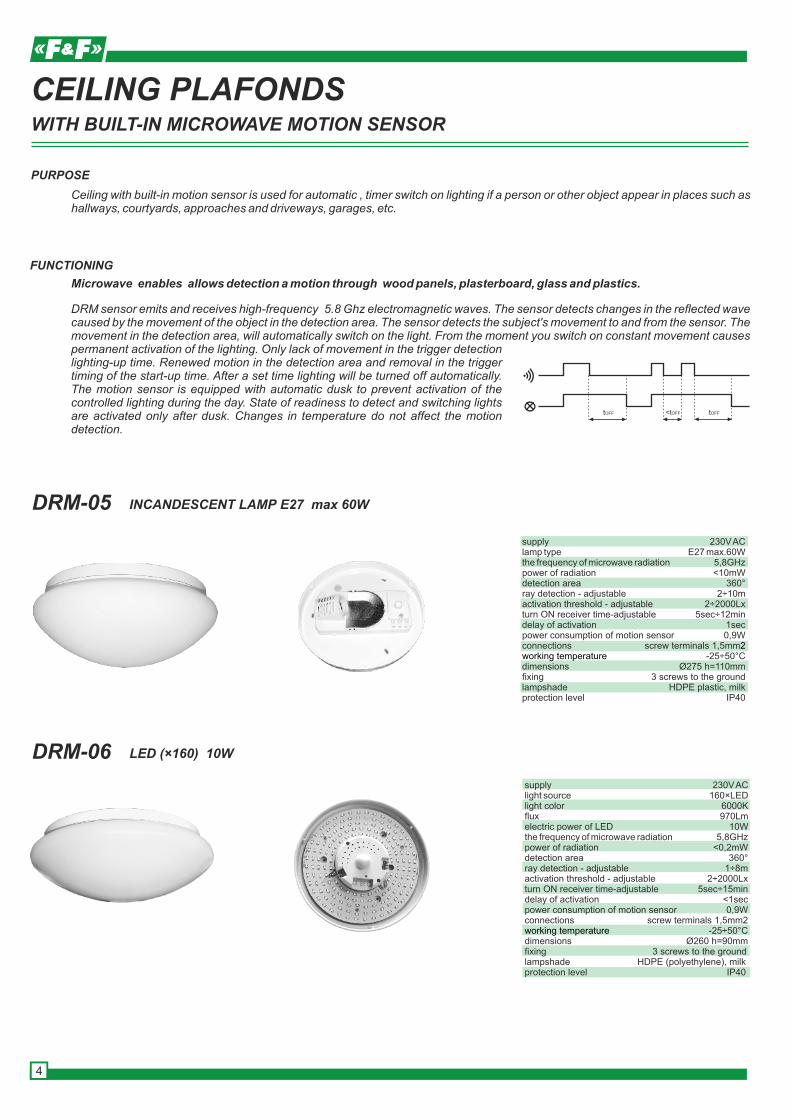
DRM-05 INCANDESCENT LAMP E27 max 60W
DRM-06 LED (×160) 10W
supply 230V AClamp type E27 max.60Wthe frequency of microwave radiation 5,8GHzpower of radiation <10mWdetection area 360°ray detection - adjustable 2÷10mactivation threshold - adjustable 2÷2000Lxturn ON receiver time-adjustable 5sec÷12mindelay of activation 1secpower consumption of motion sensorconnections screw terminals 1,5mm
-25÷50°Cdimensions Ø275 h=110mmfixing 3 screws to the ground lampshade HDPE plastic, milk protection level IP40
0,9W2
working temperature
CEILING PLAFONDS
tOFF tOFF<tOFF
FUNCTIONING
DRM sensor emits and receives high-frequency 5.8 Ghz electromagnetic waves. The sensor detects changes in the reflected wave caused by the movement of the object in the detection area. The sensor detects the subject's movement to and from the sensor. The movement in the detection area, will automatically switch on the light. From the moment you switch on constant movement causes permanent activation of the lighting. Only lack of movement in the trigger detection lighting-up time. Renewed motion in the detection area and removal in the trigger timing of the start-up time. After a set time lighting will be turned off automatically. The motion sensor is equipped with automatic dusk to prevent activation of the controlled lighting during the day. State of readiness to detect and switching lights are activated only after dusk. Changes in temperature do not affect the motion detection.
Microwave enables allows detection a motion through wood panels, plasterboard, glass and plastics.
Ceiling with built-in motion sensor is used for automatic , timer switch on lighting if a person or other object appear in places such as hallways, courtyards, approaches and driveways, garages, etc.
PURPOSE
supply 230V AClight source 160×LEDlight color 6000Kflux 970Lmelectric power of LED 10Wthe frequency of microwave radiation 5,8GHzpower of radiation <0,2mWdetection area 360°ray detection - adjustable 1÷8mactivation threshold - adjustable 2÷2000Lxturn ON receiver time-adjustable 5sec÷15mindelay of activation <1secpower consumption of motion sensor 0,9Wconnections screw terminals 1,5mm2
-25÷50°Cdimensions Ø260 h=90mmfixing 3 screws to the groundlampshade HDPE (polyethylene), milkprotection level IP40
working temperature
WITH BUILT-IN MICROWAVE MOTION SENSOR
4
ELECTRICITY CONSUMPTION METER
SO
+
9 8
PURPOSE
LE is static (electronic) calibrated electricity consumption meter is used as the display sub meters to report of the active power of three-phase AC .
FUNCTIONING
The electronic system by the influence of the flowing current and the applied voltage generates pulses in proportion to the electricity consumed. Energy measurement system takes place in Aron system. Indicators have pulse output SO + - SO-. Indicators are sealable terminal covers input and output bypass to prevent making the index.
Y
reference voltage 3×400Vbasic current 3×10Amax current 3×100Amin current 0,04Aaccuracy in accordance with the
<10VA; <2W
working temperature -20÷50°Cprotection level IP20connections screw terminals 25mm² dimensions 7 modules(122mm) fixinng on the rail TH-35
IEC61036 class 1 own power meter meter display range 999999,9kWhmeter constant (1,25Wh/imp) 800imp/kWhindication of the current consumption 2×LED redsignal read-out LED redpulse output SO+ SO- open collectorvoltage connection SO+ SO- <30V DCcurrent connection SO+ SO- <27mAconstant SO+ SO- (1,25Wh/imp) 800imp/kWh
POWER LIMITER
N
1 2 3 4 6
8 9 10 12
L
7
R
FUNCTIONS
PURPOSE
Power limiters are used to automatically disconnect the power supply from electrical circuit in excess of a fixed power consumed by the receiver in this circuit. In addition, surge disconnects the receiver in excess of or a reduction in the supply voltage.
- Adjustable activation threshold of 1 ÷ 10 kW- Protection of voltage reduction UL (150 ÷ 210V)- Protection of increase in the supply voltage UH (230 ÷ 260)- meter of relay activations with automatic power off the system after exceeding a fixed number of actuations- Automatic power lock system for 10min. in the case of 5-fold excess power- Automatic power off in case of power 8-fold higher than the set threshold- Automatic power off in case of power of more than 16kW- Adjustable activation time (1sec ÷3min)- Adjustable re-activation time (4sec ÷6min )
Y
supply 230V ACjoint separate 1Pload <16Apoweractivation threshold -adjustable 1÷10kWactivation time -adjustable 1÷300secreturn time - adjustable 4÷600secvoltageactivation threshols up UL 150÷210V down UH 230÷260Vactivation time up 5sec down 0,3secbore diameter 5mmworking temperature -25÷50ºCdimensions 3 modules (52mm)fixing on the rail TH-35
WITH RELAY VOLTAGE FUNCTIONWITH THROUGH CHANNEL FOR CURRENT CABLE OF RECEIVER
5
OM-633
LE-05dTHREEPHASE 3×400V WITHOUT NEUTRAL CABLEMeasurement in the Aron system.
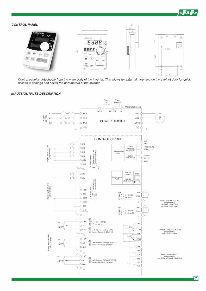
INVERTERS
PURPOSE
Inverters are electronic group of frequency converters are designed for smooth speed control of asynchronous three-phase motors.
KEY FUNCTIONS
TYPES
* The design of efficient inverter-based 32-bit DSP processor ensures fast and effective implementation of advanced control algorithms, asynchronous three-phase motor* Ability to work in speed control mode or torque control mode* Motor control based on vector control (both sensorless and with speed-feedback loop), and control based on the freely programmable V / F.* Automatic slip compensation, and a large starting torque (up to 180% at a frequency of 0.25Hz).* Multi-function control panel connected to the inverter on a "hot-plug" with the possibility of simultaneous storage of up to four sets of parameter settings and feature an easy transfer settings from one inverter to another* Mode PLC - programmable up to seven steps performed once or periodically by the inverter. For each step, you can determine the speed, acceleration and duration.* Large programming freedom inverter inputs and outputs, both analog and digital.* Built-in RS485 Modbus RTU protocol support allows plugging the inverter to fieldbus and remote control, monitoring and configuration of the inverter
Control panel is detachable from the main body of the inverter. This allows for external mounting on the cabinet door for quick access to settings and adjust the parameters of the inverter.
7
SPECIFICATIONS
Items Specifications
Supply Supply and frequency 1x230V
3 x 380~415V (±15%), 50/60Hz (±5%)
Output voltage 3x230V (to supply 230V)
3x380~400V (t o supply 400V)
Output frequency 0.00~320.0Hz
Control Characteristics V/F
1) Constant torque characteristics
2) Characteristics of the reduced torque (3 types)
3) Characteristics of the t orque set by the user (8 points)
4) Vector control (sensorless or closed-loop)
Control V/F Sensorless vector control Vector control with
feedbac
Starting torque 180% dla 0.50Hz 180% dla 0.50Hz 180% dla 0.0Hz
The dynamics of speed control 1: 100 1: 200 1: 2000
The stability of the output speed ±0.5% ±0.2% ±0.02%
Torque boost In this mode V/F control - automatic or user-defined
Acceleration / deceleration Linear or by programmed curve S.
Maximum acceleration and braking - 3200S
Frequency Accuracy Digital frequency reference:0.01Hz(f <= 100Hz), 0.1Hz (>100Hz);
Analog frequency reference: 1% of maximum frequency
Overload 1) 150% the rated current for 1 minute,
2) 200% rated current for 0.1s.
Motor slip compensation In this mode V/F control can automatically compensate for the slip
Security
Security of inverter
1) Before too high or too low supply voltage
2) Prior to exceeding the maximum current
3) Before the load is too high
4) Before losing speed and stall
5) Within the current to ground
6) Prior to excessive overheating inverter
7) In addition, the inverter is protect ed against communication errors or
incorrect feedback signal.
Safety switch Can be programmed as input or button on the safety switch causing immediate image
voltage of the inverter output.
Security settings Possibility to secure the set t he inverter to use a PIN
Deleting mistakes You can set both automatic and manual reset errors
Braking DC braking, and using an external braking resistor.
IO
6 digital inputs
1) Trigger inputs for both low-level (COM) and high (+24 V)
2) A large freedom of programming functions - it is possible to assign to the
terminals 68 different functions. Among other things, running back and
forth, trying to run back and forth, safety switch, reset, multi-speed control,
motor potentiometer, change of acceleration and deceleration, pulse
input, and more.
3 analog inputs
1) They can work both as input voltage (-10V ~ +10 V or 0 ~ 10V) and input
current 0 ~ 20mA (software, you can set the range of 4 ~ 20mA).
2) The analog inputs can be used t o ask frequency and time, and to
cooperate with PID controller.
2 analog outputs
1) 1) They can work both as a voltage output 0 ~ 10V) and output current 0 ~
20mA.
2) 2) analog outputs can be programmed to indicate:
a Setpoint and actual frequency
b Voltage and output current
c DC voltage on the track
d Temperatures IGBT power amplifier
e Power output
f Engine speeds
g Torque Drive
2 transistor outputs
1) Fast pulse outputs (max. frequency 50kH). Possible signaling:
a desired frequency
b Actual frequency
c The current values
d Output Voltages
e DC voltage on the track
f Temperatures of power amplifier
g Output power
2) Overload of transistor – max. 20mA/27V
8
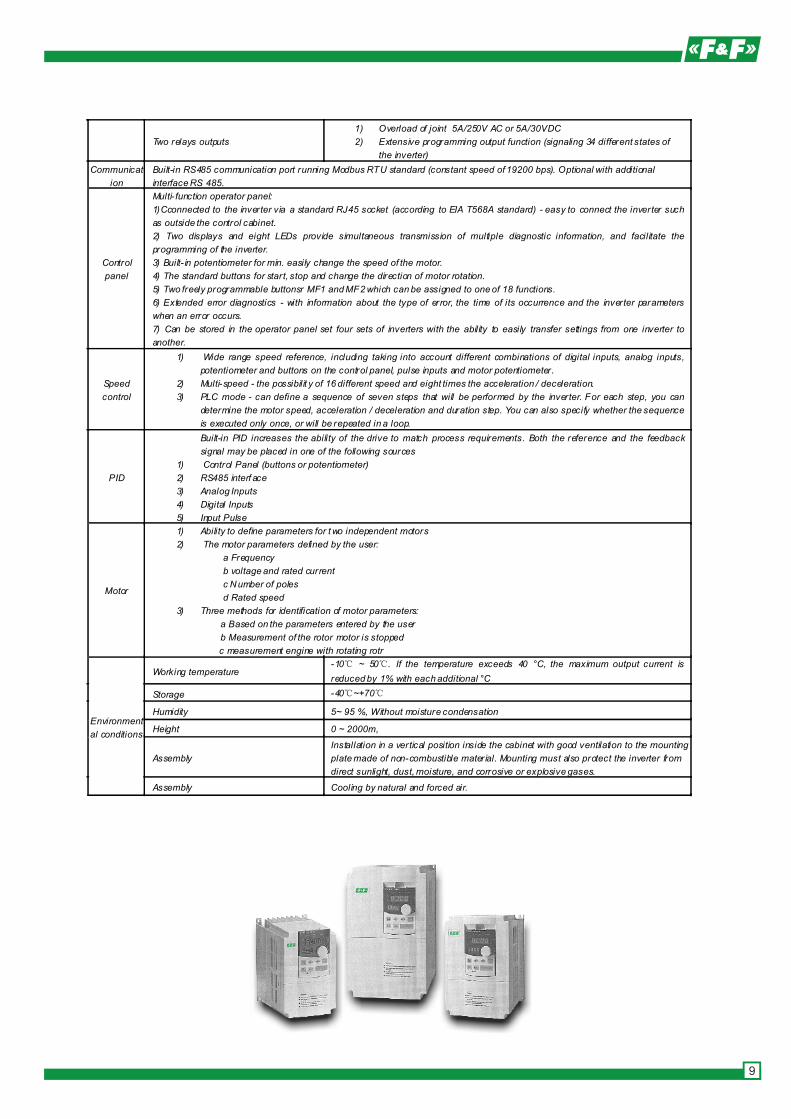
Two relays outputs
1) Overload of joint 5A/250V AC or 5A/30VDC
2) Extensive programming output function (signaling 34 different states of
the inverter)
Communicat
ion
Built-in RS485 communication port running Modbus RTU standard (constant speed of 19200 bps). Optional with additional
interface RS 485.
Control
panel
Multi- function operator panel:
1)Cconnected to the inverter via a standard RJ45 socket (according to EIA T568A standard) - easy to connect the inverter such
as outside the control cabinet.
2) Two displays and eight LEDs provide simultaneous transmission of multiple diagnostic information, and facilitate the
programming of the inverter.
3) Built- in potentiometer for min. easily change the speed of the motor.
4) The standard buttons for start, stop and change the direction of motor rotation.
5) Two freely programmable buttonsr MF1 and MF2 which can be assigned to one of 18 functions.
6) Extended error diagnostics - with information about the type of error, the time of its occurrence and the inverter parameters
when an error occurs.
7) Can be stored in the operator panel set four sets of inverters with the ability to easily transfer settings from one inverter to
another.
Speed
control
1) Wide range speed reference, including taking into account different combinations of digital inputs, analog inputs,
potentiometer and buttons on the control panel, pulse inputs and motor potentiometer.
2) Multi-speed - the possibilit y of 16 different speed and eight times the acceleration / deceleration.
3) PLC mode - can define a sequence of seven steps that will be performed by the inverter. For each step, you can
determine the motor speed, acceleration / deceleration and duration step. You can also specify whether the sequence
is executed only once, or will be repeated in a loop.
PID
Built-in PID increases the ability of the drive to match process requirements. Both the reference and the feedback
signal may be placed in one of the following sources
1) Control Panel (buttons or potentiometer)
2) RS485 interf ace
3) Analog Inputs
4) Digital Inputs
5) Input Pulse
Motor
1) Ability to define parameters for t wo independent motors
2) The motor parameters defined by the user:
a Frequency
b voltage and rated current
c Number of poles
d Rated speed
3) Three methods for identification of motor parameters:
a Based on the parameters entered by the user
b Measurement of the rotor motor is stopped
c measurement engine with rotating rotr
Environment
al conditions
Working temperature -10℃ ~ 50℃. If the temperature exceeds 40 °C, the maximum output current is
reduced by 1% with each additional °C
Storage -40℃~+70℃
Humidity 5~ 95 %, Without moisture condensation
Height 0 ~ 2000m,
Assembly
Installation in a vertical position inside the cabinet with good ventilation to the mounting
plate made of non-combustible mater ial. Mounting must also protect the inverter from
direct sunlight, dust, moisture, and corrosive or explosive gases.
Assembly Cooling by natural and forced air.
9
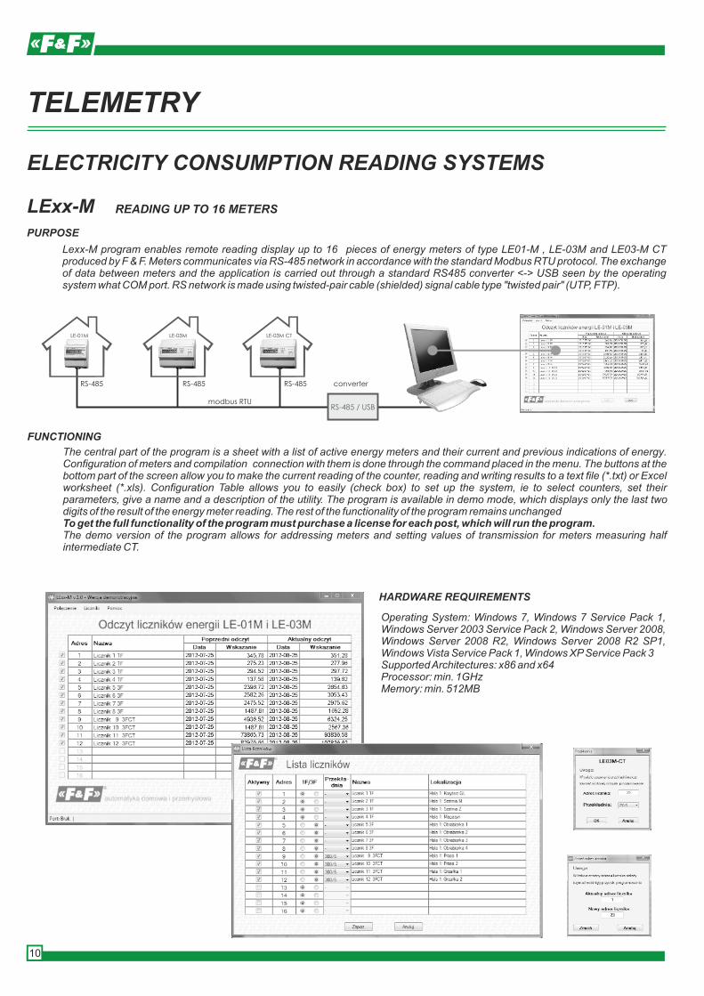
The central part of the program is a sheet with a list of active energy meters and their current and previous indications of energy. Configuration of meters and compilation connection with them is done through the command placed in the menu. The buttons at the bottom part of the screen allow you to make the current reading of the counter, reading and writing results to a text file (*.txt) or Excel worksheet (*.xls). Configuration Table allows you to easily (check box) to set up the system, ie to select counters, set their parameters, give a name and a description of the utility. The program is available in demo mode, which displays only the last two digits of the result of the energy meter reading. The rest of the functionality of the program remains unchangedTo get the full functionality of the program must purchase a license for each post, which will run the program.The demo version of the program allows for addressing meters and setting values of transmission for meters measuring half intermediate CT.
Lexx-M program enables remote reading display up to 16 pieces of energy meters of type LE01-M , LE-03M and LE03-M CT produced by F & F. Meters communicates via RS-485 network in accordance with the standard Modbus RTU protocol. The exchange of data between meters and the application is carried out through a standard RS485 converter <-> USB seen by the operating system what COM port. RS network is made using twisted-pair cable (shielded) signal cable type "twisted pair" (UTP, FTP).
TELEMETRY
ELECTRICITY CONSUMPTION READING SYSTEMS
LExx-M READING UP TO 16 METERS
PURPOSE
Operating System: Windows 7, Windows 7 Service Pack 1, Windows Server 2003 Service Pack 2, Windows Server 2008, Windows Server 2008 R2, Windows Server 2008 R2 SP1, Windows Vista Service Pack 1, Windows XP Service Pack 3Supported Architectures: x86 and x64Processor: min. 1GHzMemory: min. 512MB
FUNCTIONING
HARDWARE REQUIREMENTS
RS-485 / USB
converterRS-485
LE-01M LE-03M LE-03M CT
RS-485 RS-485
modbus RTU
10
The application is an integral part of Excel. Read the data program presents of the program. Data can be any shape as functions of spreadsheet software. Program as part of their workbook consists of four sheets; 1) Sheet Measurements - table with a list of active counters and their current indications energy.2) Set the Modbus - select types of meters, their name and a description of the type of connection and setting3) Interfaces - setting the communication parameters (IP address, COM, name)4) Logs - registration and description of communication errorsThe program is available in demo mode, which displays only the last two digits of the result of the energy meter reading. The rest of the functionality of the program remains unchanged. To get the full functionality of the program must purchase a license (electronic key), and a license for each counter are part of the system.The demo version of the program allows for addressing meters and setting values of transmission for meters measuring half
in the table
METERNETPURPOSE
MS Office 2003, MS Office 2007, MS Office 2010.
FUNCTIONING
SOFTWARE REQUIREMENTS
portserverRS-485
LE-01M LE-03M LE-03M CT
RS-485 RS-485
modbus RTU TCP/IP
internet
LAN [ethernet]
RS-485-
TCP/IP
TCP/IP
READING UP TO 1000 METERS
METERNET program enables to remote reading of indicators up to 1000 energy meters type LE01-M, LE-03M and LE03-M CT produced by F&F. Meters communicates via RS-485 network in accordance with the standard Modbus RTU protocol. The exchange of data between meters and the application is done via a standard RS485 converter <-> USB port or server on the LAN (Ethernet). In the case of a LAN to the router with a static IP address, you can read data via the Internet.RS network is made using twisted-pair cable (shielded) signal cable type "twisted pair" (UTP, FTP).
CONVERTERS
RS485>TCP/IP
ATC-2000
supply 9÷24V DCconnector RS 1,0mm²connector TCP RJ45 socketdimensions 86×100×26fixing two screw to the ground
9VDC power adapter included
RS485>USB
WE1800BT
length of cable 1,8mconnector RS485 2×0,34mm2
11
REMOTE READING TECHNOLOGIES,OF REGISTRATION, MONITORING AND CONTROL
FUNCTIONING
PURPOSE
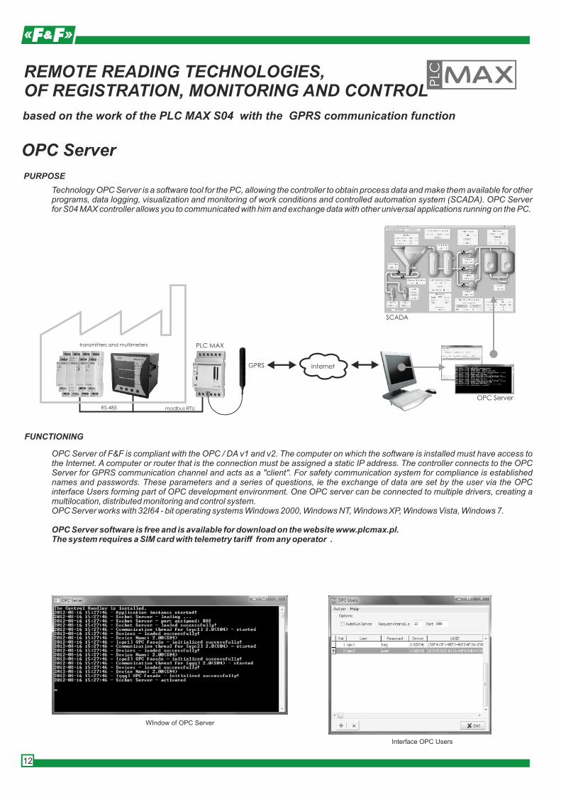
Technology OPC Server is a software tool for the PC, allowing the controller to obtain process data and make them available for other programs, data logging, visualization and monitoring of work conditions and controlled automation system (SCADA). OPC Server for S04 MAX controller allows you to communicated with him and exchange data with other universal applications running on the PC.
based on the work of the PLC with the GPRS communication f MAX S04 unction
SCADA
RS-485 modbus RTU
PLC MAX
GPRS internet
OPC Server
transmitters and multimeters
OPC Server
OPC Server of F&F is compliant with the OPC / DA v1 and v2. The computer on which the software is installed must have access to the Internet. A computer or router that is the connection must be assigned a static IP address. The controller connects to the OPC Server for GPRS communication channel and acts as a "client". For safety communication system for compliance is established names and passwords. These parameters and a series of questions, ie the exchange of data are set by the user via the OPC interface Users forming part of OPC development environment. One OPC server can be connected to multiple drivers, creating a multilocation, distributed monitoring and control system.OPC Server works with 32I64 - bit operating systems Windows 2000, Windows NT, Windows XP, Windows Vista, Windows 7.
OPC Server software is free and is available for download on the website www.plcmax.pl.The system requires a SIM card with telemetry tariff from any operator .
WIndow of OPC Server
Interface OPC Users
12
FUNCTIONING
PURPOSE
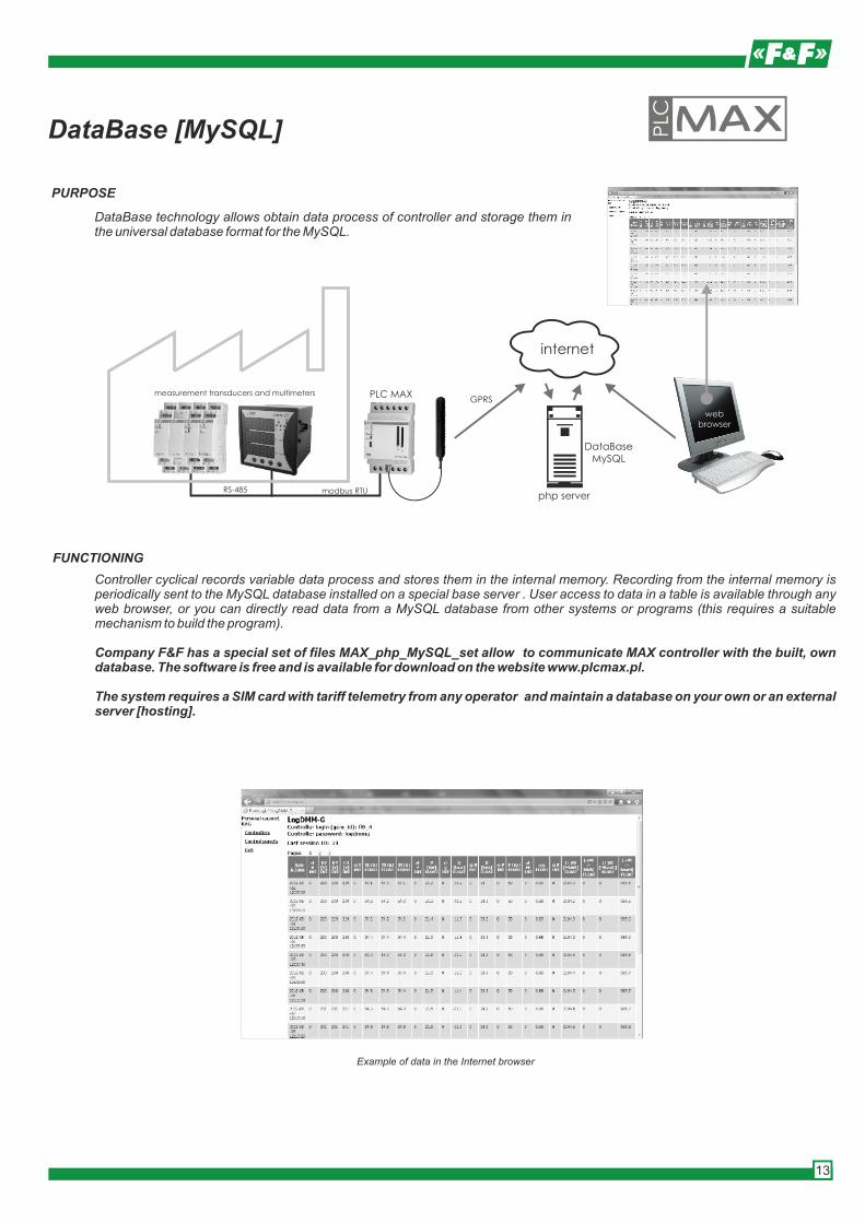
DataBase technology allows obtain data process of controller and storage them in the universal database format for the MySQL.
RS-485 modbus RTU
PLC MAXmeasurement transducers and multimeters
DataBase [MySQL]
GPRS
webbrowser
internet
Controller cyclical records variable data process and stores them in the internal memory. Recording from the internal memory is periodically sent to the MySQL database installed on a special base server . User access to data in a table is available through any web browser, or you can directly read data from a MySQL database from other systems or programs (this requires a suitable mechanism to build the program).
Company F&F has a special set of files MAX_php_MySQL_set allow to communicate MAX controller with the built, own database. The software is free and is available for download on the website www.plcmax.pl.
The system requires a SIM card with tariff telemetry from any operator and maintain a database on your own or an external server [hosting].
php server
DataBaseMySQL
Example of data in the Internet browser
13
MAX ControlUni PC for Windows PC
VISUALIZATION PROGRAM OF DATA PROCESSfor programmable controllers MAX Series S and H with the function of SMS communication
PURPOSE
Program for use on the PC to work with MAX controller for remote control and visualization parameters of the low level of automation of technological advancement.
The program communicates with the controller via a computer modem 3G. Data exchange takes place in the SMS mode. The program has a field project on which you can attach a jpg image as the object visualization and automation system. Placed on visualization software components, such as buttons, labels and displays (button / label / display). For those objects are defined macros, or programming instructions for the driver. Action request / response is forced manually or cyclically with a period defined in the macro of the object.Normally MAX controllers are not designed to work with the program. Activation license must be purchased for each driver working in the system.ControlUni software is free and is available for download on the website www.plcmax.pl
Data exchange takes place in the SMS mode. The program has programmatic objects, such as buttons, labels and displays (button / label / display). For those objects are defined macros, or programming instructions for the controller. Action request / response is forced manually or cyclically with a period defined in the macro of the object.MOBILE ControlUni software is paid. The application can be downloaded directly to your mobile device from internet shop GooglePLAY.
FUNCTIONING
FUNCTIONING
HARDWARE REQUIREMENTS
PLC MAX
SMS SMSmodem
3G
The program cooperate with the dedicated 3G modems:Huawai E171, Huawai E173.
MAX ControlUni MOBILE for devices running on ANDROID
PURPOSE
Program intended for mobile devices running Android to work with MAX controllers for remote control and reading the parameters of home automation and industrial low level of technological advancement.
SMS
Pompa ON OK
Pompa OFF ID=64
Czas pracy [h] 3657
14
NETWORK PARAMETERS REGISTRATION PACK
LogDMM-G
MAX controller and multimeter DMM-3T communicate with the RS485 port using Modbas RTU communication protocol. The controller cycle records the read network parameters and stores them in the internal memory. Recording from the internal memory is periodically sent to the MySQL database installed on a special base server. User access to data in a table is available through any web browser. Data can be deleted or imported to your computer as a text file. There is also the ability to directly read data from a MySQL database from other systems or programs (this requires the construction of a separate program).
Recorded parameters: - date [YYYY-MM-DD] - active power (P) [1kW] - Positive active energy(+Wh) [kWh] - time [ hh: mm : ss] - reactive power (Q) [1kVar] - Negative active energy (-Wh) [kWh]- voltage of three phases (U1, U2, U3) [1V] - apparent power(S) [1kVA] - Positive reactive energy( (+varh) [kvarh]- current of three phases(I1, I2, I3) [1A] - power factor (cosφ) - negative reactive energy(-varh) [kvarh]- network frequency (FREQ) [1Hz]
Simultaneously recorded parameters are correct reading registers (status):0 - read correctly, 16 - no answer, for example, the multimeter off, broken communication cable, etc., 17 - checksum incorrect response (incorrect result), for example, an error resulting from disturbances on the communication line.Cycle registers read and write to the internal memory and the transmission cycle [backup] to the database are set by the user. The minimum read cycle time is 1.0 sec records.The system requires a SIM card with tariff telemetry from any operator and buy a hosting service, or maintain a database on external server F&F
FUNCTIONING
PURPOSE
COMPONENT
Display data in a web browser
Pack is used to read and registration phase network parameters and remotely send data to MySQL base via GPRS communication.
MAX H02 controller, multimeter DMM-3T, gel battery ACCU-HP1,-12V 3Ah, termination modules LT-04 (2 pcs), mini USB cable> USB, software + manual. 24V power adapter available separately (eg, ZI-24).
Any adjustments cycle times, dates, times, and perform backup is done by using a special program menu on your computer.
Menu program LogDMM-G on PC
DMM-3T MAX H02 LT-04 ACU 12V 1,3Ah CD soft USB wire
L3
L2
L1
N
5A 5A5A
RS-485
GPRSweb
browser
modbus RTU
internet
POWER
S1 S2 S3 DP
DN
GND
GND
+BAT
+24V
GND
DI/AI1
DI/AI2
DI/AI3
DI/AI4
DI5
DI6
DI7
DO1
DI8
DO2
GND
DO3
GND
DO4
MIC
+
MIC-
Logic -H02
STATUS
GSM
serwer
15
SIMply MAX P01 ON / OFF / INFORM
FUNCTIONING
FUNCTIONS
PURPOSE
P01 relay with built-in GSM communicator is used to remote control using a mobile phone. Enables you to easily manage and control the state of the outputs of devices connected to the controller inputs.
The relay operates in the mobile communications network GSM 900/1800 any operator in Poland (no simlock). To be able to make calls and perform the desired function must have a valid SIM card. The relay has two relay outputs which are implemented by functions start and stop controlled receivers and two high voltage inputs, which are implemented through notification of activation functions controlled devices. Commands and notification specified SMS texts exchanged between the controller and user phone.
REMOTE CONTROL RELAYS
* Switching on and off outputs. Example: WY1ON - enable output. 1, WY2OFF - disable output 2* Temporary output switch. Example: WY1ON S 30 - switching output 1 time for 30 seconds. (Interval 1 ÷ 300sec); WY1ON M 10 - switching output 1 time for 10 minutes. (Interval 1 ÷ 600min)* SMS to the phone user to input activation. Example: WE1 ON - high (1) Input 1, IN2 OFF - low (0) at the input of second* Request input or output state. Example: WE1? - Ask about the status of input 1 -> answer: WE1 ON / OFF WE1; OUT1? - query output state 1 -> answer: OUT1 ON / OFF OUT1* Password (4 to 8 digits). When working with password command option must be preceded by a password, eg 1234 WY1ON. configuration SMS commands: PASSWORD ON - enabling the option of a password, PASSWORD OFF - disable the password, PASSWORD ON xxxxxxxx - change the password, such as PASSWORD ON 12345678* Configuration of inputs: we give your phone number for which you want to send the message and at what state: WE1! +48123456789 ON - notification no status set high on the input. 1 WE1! +48123456789 OFF - notification no status set low on the input. 1 WE1! +48123456789 NF - notification no status set high and low for the input. 1* Inquiries about the status of inputs and outputs. Example: WE1? - Ask about the status of input 1 -> answer: WE1 ON / OFF WE1; OUT1? - inquiry the output state 1 -> answer OUT1 ON / OFF OUT1* Automatic answer (as an option). Word RIP major orders, np.WY2ON RIP. Content response: OK.* Automatic recovery of output after power (out of memory). Configurable option MEMORY ON command. Disabling MEMORY OFF command.
Y
supply 230V ACinputs number 2 voltage tolerance 160÷260V ACrelay outputs number 2 type 1Z (1NO) overload <8Aports SIMpower consumptionworking temperatureconnections screw terminals 1,5mm²fixing 3 modules (52mm)
-10÷50°C
6WE2
L
WY2
9 10
11 12
L
L N
WE1
WY1
5
7 8
POW
STAT
GSM
SIM
7
1
8
2
9
3
10
4
11
5
12
6
SIMply MAX P01
F&F
SIM
SMSIN
OUT
16
GSM REMOTE CONTROL
SIMply MAX P02 WITH CLIP FUNCTION
FUNCTIONING
FUNCTIONS
COSTS
PURPOSE
MAX P02 relay with built-in GSM communicator is used to remotely open the automatic gates, garage doors, barriers and gates with your mobile phone. It is used for objects with protected access and a large number of users with permission to enter, such as housing, garages, car parks and public company, etc. It eliminates the traditional control of the radio transmitters and the cost associated with the purchase of a large number of users.
The relay operates in the mobile communications network GSM 900/1800 any operator in Poland (no unlock). To be able to make calls and perform the desired function must have a valid SIM card. The relay has two control pins, which are actuated by the driver pulse gate or lock the gate. Both outputs are run in parallel, but with any fixed contact closure times (pulse). Self control is done no cost. The user initiates a connection to the number of standard controller. The controller automatically identifies the number and refuses to connect at the same time activating the output (dialup CLIP function). In addition, it is possible to drive the output using the control buttons are connected to the inputs of the relay. The relay has a working range of options: manual or automatic closing. In automatic mode, the relay output is activated by the user activates itself again after a certain time in order to close the gate.The phone numbers of users and pulse times and automatic shutdown are determined by the configuration program on your PC. The connection to the relay via USB cable.
* Costless control for users (dialup function CLIP)* Two parallel relay outputs* Ability to set different output activation time for each output separately (eg simultaneous control gate and gate)* Two pulse inputs allowing for manual activation outputs connected via external buttons* Auto shutdown after a certain time* User authentication 500 numbers* PC configuration program
Given the current rate of GSM operators for tariff type of SIM cards cost of the controller can reach up to 5 ÷ 10 zł per year.
pre-paid
Y
supply 230V ACinputs number 2 voltage tolerance 160÷260V ACrelay outputs number 2 type 1Z (1NO) overload <8Aports SIMpower consumptionworking temperatureconnections screw terminals1,5mm²dimensions 3 modules (52mm)
-10÷50°C
6IN2
L
OUT2
9 10
11 12
L
L N
IN1
OUT1
5
7 8
NO-COST GSM CONTROL GATE, WICKET, BARRIER
POW
STAT
GSM
USB
SIM
7
1
8
2
9
3
10
4
11
5
12
6
SIMply MAX P02
F&F
SIM
USB
CLIPIN
OUT
Configuration program
OUT1 [sec]
OUT2 [sec]
1
5
read
write
SIMply MAX P02 Config ×
impuls
OUT1 [sec]
OUT2 [sec]
20
5
auto OFF
17
MAX S03 ON / OFF / INFORM
MAX S03 CONFIG
FUNCTIONING
PURPOSE
MAX S03 controller is freely programmable logic controller (PLC) with built-in GSM communicator. It is designed for solving control and exchange via the mobile phone SMS connection mode. The controller can operate as a unit of work with a rigid algorithm whose parameters and functions are set using MAX_S04 CONFIGURATOR or as freely programmable logic controller, the logic of the work as a whole is determined by the application (program ForthLogic or LAD).
data
Task notification alerts you realize one of the six members whose phones are stored in the appropriate configuration menu items when there is a logical tripped on one of the inputs. The tripping logic of the digital inputs is called closed circuit between the input and ground GND (logic value 1). For analog input is exceeded the threshold value for a given input. The notification is implemented as an SMS message. Task output control allows you to:- Remote control digital outputs control commands sent by SMS as text;- Implement a simple controller based on physical values of any of the analog inputs and digital outputs.Automatic control of one of the digital outputs in the ordinary course of physical control is the fact that the measured value exceeds the threshold set for the digital output is switched to the active state.
PROGRAMMABLE CONTROLLER WITH GSM COMMUNICATOR
- +
12 11
D2 D5
D1
D3
D4
D6
1
2
3
4
5
6
AI1 AI27 8
Y
supply 9÷30V DCIN/OUT digital DIO (30V; 0,2А) 6analog inputs 0/4÷20mA / 10 bitów 2 working temperaturepower consumption 8Wconnections screw terminals 1,5mm²dimensions 3 modułes (52mm)fixing on the rail TH-35
-20÷50°C
MAX S03 is one of the few controllers to enable the connection and use the elements without programming. Through CONFIGURATOR can use it, anyone who does not want to learn languages and complicated procedures PLC programming.
SMS
18
FUNCTIONS
DIGITAL INPUTS AND OUTPUTSWiring diagram depending on the selected function digital D.Digital outputs (DO): D1 digital D2.Digital inputs (DI): D3, D4, D5, D6. The tripping logic of digital input is closed the circuit between this input and ground (GND) [boolean 1].ANALOG INPUTSA schematic diagram of connecting analog sensors of different types.
IMPLEMENTATION OF CONNECTIONS
MAX S03
U
ST
GSM
1 2 3 4 5 6
7 8 9 10 11 12
4-20mA
4-20mA
x
-+
+
-+
x
MAX S03
U
ST
GSM
1 2 3 4 5 6
7 8 9 10 11 12
+ -
- Record numbers of users that will be implemented notification and remote control- Authorization of phone numbers of incoming calls- Setting password. Password precedes the content of SMS commands- Output control by SMS commands- Ask about the status of inputs and outputs SMS commands- SMS messages to the mobile user for actuation of digital inputs- SMS messages to the mobile user to the pre-determined threshold on the analog input- The definition of the content of the SMS message output (up to 160 characters)- Optional set number of minutes, after which the SMS message will be repeated in the case of the continuous maintenance of the entrance- Control output depending on the assigned input: LEVEL option - mapping of (EC 1 -> O 1, EC 0 -> O 0); PULSE - time, output set time after activation of the input.- Function digital controller based on the definitions of scale analog input, and assigned him to the threshold of the output- Scaling the actual values measured by the analog input range- Setting the PIN code for the SIM card (if required)- Selecting signal (high state 1 or low state 0) at the input trigger an SMS message- Synchronize the system time of the controller with a time of a connected computer, set the time zone and daylight saving time automatic summer-winter
SOFTWARE TOOLS
MAXLadderSOFT program provides an easy way to convert schema "relay" on the programming language controller. The program allows to create and edit applications using ladder diagram language [LAD] validate the design scheme, direct communication with a computer controller, upload applications to the memory controller.
Interactive development environment for creating applications and controllers in ForthLogic MAX has a text editor Notpead + +, the PuTTY terminal and Programmer ForthLogic program providing two-way communication between the PC and the controller MAX. Your environment, you can create scripts in the language ForthLogic MAX controllers program and communicate with the controller in terminal mode.
Direct work with the system controller mode called box. There are two types of dialogue work: terminal and remote. Terminal mode is the work of a program HYPERTERMINAL (MAX-PC with a USB cable). Terminal mode mainly use for learning programming, solving programming tasks or solving existing problems in the operation of the controller. Remote mode - only for controllers with GSM module - this controllers work with your phone via SMS. In this mode, the phone screen is similar in purpose to a terminal window on your computer monitor. Remote mode obviously use remote control devices connected to the
HyperTerminal
MAX-LadderSOFT
Notepad++PuTTYForthLogic Programer
19
WIRELESS INTELLIGENT HOME SYSTEMwww.fhome.pl
STANDARD OF THE FUTURE IN OUR HOME
The F&Home Radio system is an innovative and comprehensive solution for the design and installation of network management and remote equipment or devices that are an integral part of the building. Through the use of universal radio actuators and sensory control the operation of each device, the system allows the integration of previously low communication wireless system components: lighting, heating, air conditioning, ventilation, access control, security, audio-video systems and automation garden system.
SYSTEM ARCHITECTURE
The F&Home Radio is built based on a central server controlling all its functions. The server, based on Embedded Linux operating system has a high performance and reliability at very low power (4W). The server communicates by radio in the 868 MHz band of the sensory elements - the so-called. sensors (i.e.switches, motion detectors, temperature probes, humidity and other sensors) and actuators - the so-called. actuators (relays, dimmers, control modules, LED, drivers of electric motors, pumps, valves and water heaters, and other actuators). By using two radio modules operate simultaneously in two independent channels, the system has a very high resistance to external interference. Radio range, typically amounting to tens of meters, can be extended by using repeaters (signal enhancing module).
Both sensors and actuators in the F&Home Radio are universal. For example, motion sensor in the absence of family members can act as an alarm sensor and the alarm disarmed can switch light, or ventilation system settings change depending on the activity of the household. Similarly, power regulator can control the intensity of light or the fan thrust bathroom. This approach means that the available range of sensory and regulatory elements in no way limits the functionality of the system and on the contrary - it significantly expands!.Processing signals in the , F&Home Radio system done in real time (the guaranteed response time of the event and any combinations thereof is less than 30ms). F&Home Server works with a local radio network (LAN) that allows you to communicate with a wide range of mobile devices (phones, smart phones and tablets). This configuration allows you to manage, control and monitoring of the system from any device, without using external servers. The system also has direct support for communication based on SMS messages via a standard USB modem equipped with a SIM card
20
BENEFITS OF WIRELESS
* Reduction of wired connections* Non-invasive radio system components through the use of: box modules, transmitters and controllers, alternative modules on a DIN rail mounted and battery powered sensors* Warranty quick and easy installation of the new buildings and modernization of existing installations without the need for absorbing and costly repairs)* Easy reconfiguration of system components for the development house, apartment or increased requirements or changes in household preferences* The ability to connect and control the operation of already installed, and without the remote control device fitted to or an integral part of the building (eg, lighting components, automatic doors, windows, shutters / blinds, heaters, solenoid valves, circulation pumps, sprinkler systems, watering lawns and plants etc.)* A much wider range of flexibility, performance and functionality of the wired solution with the possibility of adapting or full integration
* architecture based on server that provides the unprecedented functionality by using a relatively narrow range of universal actuators and sensory* Integration of working independently devices and installation* Flexible expansion and scaling system* Small size modules to facilitate and accelerate installation, designed to work with equipment from other manufacturers* Use a wide range of mobile devices (phones, smart phones and tablets) as a universal remote or stationary or portable control panel* Integration of systems using radio communication with wired solutions (only for selected solutions!)* Limiting the number of system components by parallel use of their functionality (reduction of installation costs)* Built-in algorithms to prolong the service life of components (eg preheating for incandescent lighting)* The use of information from websites to manage the physical components of the system (eg the management of heating systems work with high inertia or plant watering systems based on the weather forecast)* Built-in astronomical clock (in conjunction with weather prediction tools allows m.in a full break with dusk sensors, reducing installation costs)* Unique design tools and system configuration
DISTINCTIVE FEATURES OF THE SYSTEM
21
LAN network
Smartphone
Radio sensors and actuators
Server
PC
Mobile
22
Architecture and various components of the system F & Home Radio has been designed to not only allow the user to remotely control the operation of individual components but also, where possible, relieve him from the necessity by autonomous intelligent management and control of devices. Depending on the type and configuration of the installed automated equipment of the building system can control his work after the diagnosis of specific household activities such as: user sleeps, wakes up, leaves the house, away from home, coming home, entering, staying in the house, put sleep - or other types of events such as the visit of guests, watch a movie, party, barbecue in the garden, etc. Here is an example implementation of an autonomous function for one of the examples of activities:
User moves closer to home - the system identifies the activity (such as GPS location, SMS message sent by the user) and automatically:* adjusts the heat (or cool reheats selected room or zone) to the preferred,* raises the blinds to the desired position (as preset by the user)* turns on lights in selected areas or zones (eg, driveway, garden, garage) and adjusts the intensity of theexternal conditions (time of day, weather conditions, personal preferences)* airs selected rooms (repealed a window or turn on the ventilation system), taking into account information from sensors (egdetection of rainfall, wind strength and direction)* starts the circulation of hot water in advance of the expected time of return (turn the pumpcirculation)* set the blinds, drapes, curtains in preferred positions, taking into account information from sensors (eg temperature control,angle to the sun)* prepare audio-video systems for media playback in certain areas or rooms* runs, controls work or prepare for work other desired device
INDEPENDENT WORK
REMOTE CONTROL
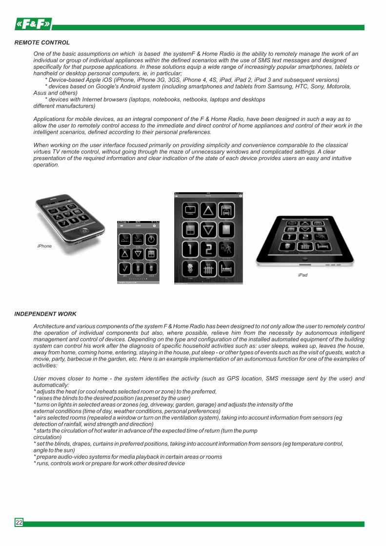
One of the basic assumptions on which is based the systemF & Home Radio is the ability to remotely manage the work of an individual or group of individual appliances within the defined scenarios with the use of SMS text messages and designed specifically for that purpose applications. In these solutions equip a wide range of increasingly popular smartphones, tablets or handheld or desktop personal computers, ie, in particular; * Device-based Apple iOS (iPhone, iPhone 3G, 3GS, iPhone 4, 4S, iPad, iPad 2, iPad 3 and subsequent versions) * devices based on Google's Android system (including smartphones and tablets from Samsung, HTC, Sony, Motorola, Asus and others) * devices with Internet browsers (laptops, notebooks, netbooks, laptops and desktopsdifferent manufacturers)
Applications for mobile devices, as an integral component of the F & Home Radio, have been designed in such a way as to allow the user to remotely control access to the immediate and direct control of home appliances and control of their work in the intelligent scenarios, defined according to their personal preferences.
When working on the user interface focused primarily on providing simplicity and convenience comparable to the classical virtues TV remote control, without going through the maze of unnecessary windows and complicated settings. A clear presentation of the required information and clear indication of the state of each device provides users an easy and intuitive operation.
iPhone
iPad
Integral part of the F&Home Radio is a support tool in the form of software configuration WiHome Configurator, dedicated mainly to installers, architects, developers, engineers, as well as industry and users - hobbyists. Software is a unique solution in the following areas: design and construction of the installation and configuration of intelligent home and building automation and management server based on the technology WiHome. With a virtual representation of the physical elements of sensory and regulations and the creation of an extensive library of software objects implementing the logic of the interaction between these elements - it is possible to easily create virtually any configuration scenarios work of individual devices, systems, and entire systems. Other advantages of this approach include* Saves time and is easy installer* Ability to perform most of the configuration work off-site installation* Simplifying and minimizing installation work at customer* Fast copying installation projects for more similar properties (multi-family housing, twin buildings, residential houses)* Easy reconfiguration of installation for system expansion or change user preferences* Remote configuration, management and maintenance
CONFIGURATION TOOL FOR INSTALLERS
Lighting:* Free configuration of points of light, space, and installation of the physical circuit design features and control panelsmobile applications* Remote control time and light intensity of individual points, separate sections and wholecircuits* Create any color compositions for RGB LED lighting* The composition of different lighting scenarios defined by the user according to his preferences* Sequential operation (eg control of different light scene using only one switch)* Free-scenes combine with the work of other systems within the defined scenarios (eg integration ofsystems, Audio-Video))* Intelligent operation depending on the time of day or night, presence detection, traffic, and other events (such as graduallight up the room in night mode)* Setting up lights for the simulation of user presence in the house while their actual absence
Heating, Air Conditioning, Ventilation:* The direct or indirect control the operation of the heating system components (drivers using ovens,electric valves, circulation pumps, ventilation systems, etc.)* The use of temperature sensors embedded in the system components* Local management of temperature and ventilation in each room or zone* Remote control working temperature and ventilation equipment at selected locations* Freedom to define scenarios modes for specific activities (eg summer operation, winter, holiday mode, shortabsence, return home, etc.)* Configuration modes for each user preferences* Intelligent operation depending on the time of day or night, household activities and other events (eg temperature adjustmentthe presence and volume of traffic in the room)* Sync to work with web services* Control and remote control using SMS gateway (eg remote management operation of the heating system in the home homes without ethernet)
EXAMPLES FOR SOME FEATURES OF INSTALLATION
23
www.fhome.pl
COMPONENTS
rH-D1S2 Box single channel dimmer module with dual channel transmitterrH-D2S2 DIN dimmer module with dual channel transmitterrH-PWM3 Three way box module low-voltage PWM controllerrH-PWM2S2 Boxmodule dual PWM controller with low voltage two-channel transmitterrH-TSR1S2 Box module bi-directional relay channel with transmitterrH-R1S1 Single channel relay module box channel with transmitterrH-R2S2 DIN relay module with dual channel transmitterrH-R5 DIN relay of five way module rH-S2L2 Box module of two channel transmitter with two LEDsrH-S4L2T1 Box module four channel transmitter unit and a temperature probe and two LEDsrH-S6- DIN six-way transmitter modulerH-P1 Low-current module, passive motion detectorrH-P1T1 Low-current module, passive motion detector with a temperature proberH-E2 Two-channel signal amplifier modulerH-IR1 Infrared remote control module (in preparation)rH-AC16S4R4 Module co-operation with the control panel (in preparation)rH-SERVER Server control and management system work
Installation of F&Home Radio can only be done by a qualified installer, who received training in the installation, maintenance and configuration. In the case of self-assembly or by the unauthorized installation company F&F may refuse to free technical support and warranty express terms of the components and assembly of the system.Authorized installer holds a personalized card with your name and authorization number.
SYSTEM INSTALLATION
FH00000
Dimension: Ø50 Dimension: 245×58×138mm
24
VIDEOINTERCOM SETS
MONITORS (PANELS)
MK-01
MK-02
MK-03
handsWorking with two camerasvolume control, brightness and colorplastic + aluminum panelblackadapter on the rail 35mm includedwall mountdimensions weight 245, height 160, depth 18
handsWorking with two camerasvolume control, brightness and colorplastic + aluminum panelwhiteadapter on the rail 35mm includedwall mountdimensions weight 245, height 160, depth 18
handsWorking with two camerasBacklit touch keyboardvolume control, brightness and colorLEDs indicationglass panelblackadapter on the rail 35mm includedwall mountdimensions weight 241, height 161, depth 23
Work configuration:1 camera + 1 monitor1 camera + 2 monitors2 cameras + 1 monitor2 cameras + 2 monitors
2 k
am
ery
+ 2
mo
nito
ry
Installation 4 wire + 2 wires to the electric opener. When using low-current electric lock 12V DC max. 300mA possible 4-wire installation (can use video intercom power supply). For installations use cables up to 30m with a minimum diameter of 0.5 mm ², 30m above the min. 0.7 mm ². For the best image quality in video and audio line is recommended to use 75 ohm coaxial cables.
INSTALLATION
MK-05
MK-04W
handsadditional control gateWorking with two camerasvolume control, brightness and colorplastic panelwhiteadapter on the rail 35mm includedwall mountdimensions weight 220, height 160, depth 25
abonent multiple, customizable system supporting up to 999 users,hands (without headset)color screen 7 "widescreen TFT LCDadjust the monitor parameters (volume, brightness and color)buttons: touch, backlitglass panelhousing color: blackcontrol of Electro-hook sequential view of the cameras in a number of door stations,preview of her head and PTZ control cursors,direct communication with concierge,elevator recallreceiving text messagesdimensions 305x145x23mmmonitor cooperate with door station: KK-07
25
MK-08handsworking with two camerasplastic panelvolume control, brightness and colorThe ability to connect two door stations(2 stations and 1 station CCTV camera + 1)128MB memorymedia playerUSB input,SD slot up to 2GBblackadapter on the 35mm rail includedwall Mountdimensions weight 220, height160, depth 25
GATE STATION
KK-01 KK-03 KK-04 KK-05
dimensions: 58×135×39 [mm]
surface surface with keypad flat webbed flat webbed with keypad
dimensions: 78×185×60 [mm]
dimensions: 150×203×43 [mm]
dimensions: 120×250×43 [mm]
KK-07 dedicated to monitor MK-05
webbed, touch keyboardindividual access codes
dimensions: 150×350×48 [mm]
KK-08 KK-08K KK-09 KK-102-abonentswebbed with keypad
dimensions: 150×335×55 [mm]
2-abonentswebbed
4-abonentswebbed
dimensions: 150×355×55 [mm]
dimensions: 150×355×55 [mm]
6-abonentswebbed
dimensions: 150×355×55 [mm]
supply 12V DCpower consumption 1,5Wangle of view 70°opening time - programs. 1÷99sconverter 1/3 CCD
oworking temperature -25÷55 Cminimum illumination 0,05 Luxbacklight LEDprotection level IP55
All gate stations can be used interchangeably with any monitor.
The exception is a set of monitor MK-05 and dedicated to them station KK-07
APPLICATION
26
KK-114-abonents webbed
dimensions: 120×250×43 [mm]
MU-01
KS-01
Intercoms cooperate with all types of monitors.The exception is the only monitor MK-05
UNIPHONES
KEYPAD
MU-02headset hands
APPLICATION
27
electromagnetic controlsupport two door stationsadjust the ringer volumecooperation with monitors: allsupply: 14,5V DC warranty: 24 monthsdimensions: 100x200x45mm
hands without headsetelectromagnetic control4-wire installationsupport two door stationsAdjusting intercom(call volume, tone)dimensions: 160x120x42Power Supply: DC/14,5 V(external power supply)
lock with proximity card readervandal-proof metal housingbuilt-in RFID proximity card readersupport for 2 zones (eg opening gates and doors)bell function (alternatively instead of 2 zones)Memory Capacity: Zone 1 - 1000 user codes and cards, Zone 2 - 10 user codes and cardsbacklit keyboardPower supply: 12 - 15V DCrelays set time: 0-99sthe ability to connect the output switchesopen door sensor inputtamper sensorcurrent consumption stand by <40mA, during work <70mA


![Catalog Roll'eat [ENG]](https://static.documents.pub/doc/80x56/568c475e1a28ab49168d94bc/catalog-rolleat-eng.jpg)


