196
Terrestrial Microwave Antenna System Products 36
| Date post: | 26-Dec-2015 |
| Category: |
Documents |
| Upload: | raul-infante-galindo |
| View: | 219 times |
| Download: | 12 times |
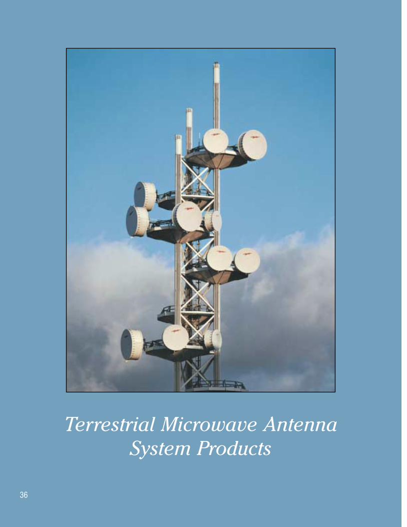
Terrestrial Microwave Antenna System Products
36

37
IndexTerrestrial Microwave Antennas
Terrestrial Microwave Antenna Nomenclature . . . . . . . . . . . . . . . . . . . . . . . . . 38Antenna Types . . . . . . . . . . . . . . . . . . . . . . . . . . . . . . . . . . . . . . . . . . . . . . . . . 39System Planning Software . . . . . . . . . . . . . . . . . . . . . . . . . . . . . . . . . . . . . . . . 44Antenna Construction . . . . . . . . . . . . . . . . . . . . . . . . . . . . . . . . . . . . . . . . . . . . 45Antenna Selection Criteria . . . . . . . . . . . . . . . . . . . . . . . . . . . . . . . . . . . . . . . . 47Electrical Specifications . . . . . . . . . . . . . . . . . . . . . . . . . . . . . . . . . . . . . . . . . . 48
Radiation Pattern Envelopes . . . . . . . . . . . . . . . . . . . . . . . . . . . . . . . . . . . . . 48Electrical Definitions . . . . . . . . . . . . . . . . . . . . . . . . . . . . . . . . . . . . . . . . . . . 49
Antenna Environmental Ratings . . . . . . . . . . . . . . . . . . . . . . . . . . . . . . . . . . . . 49Antenna Specifications and Ordering Information. . . . . . . . . . . . . . . . . . . . . . . 50
Ordering Tables by Frequency Band . . . . . . . . . . . . . . . . . . . . . . . . . . . . . . . 51Multiband Antennas . . . . . . . . . . . . . . . . . . . . . . . . . . . . . . . . . . . . . . . . . . . 92
Mechanical Specifications . . . . . . . . . . . . . . . . . . . . . . . . . . . . . . . . . . . . . . . . 95Forces Produced by Microwave Antennas . . . . . . . . . . . . . . . . . . . . . . . . . . . . 111Antenna Options . . . . . . . . . . . . . . . . . . . . . . . . . . . . . . . . . . . . . . . . . . . . . . . 114Antenna Accessories. . . . . . . . . . . . . . . . . . . . . . . . . . . . . . . . . . . . . . . . . . . . 123
ValuLine® Antennas
Introduction . . . . . . . . . . . . . . . . . . . . . . . . . . . . . . . . . . . . . . . . . . . . . . . . . . 127ValuLine Antenna Nomenclature. . . . . . . . . . . . . . . . . . . . . . . . . . . . . . . . . . . 128Antenna Specifications and Ordering Information . . . . . . . . . . . . . . . . . . . . . . 130
Ordering Tables by Frequency Band . . . . . . . . . . . . . . . . . . . . . . . . . . . . . . 131Mechanical Specifications . . . . . . . . . . . . . . . . . . . . . . . . . . . . . . . . . . . . . . . 138Forces and Twisting Moments Due to Wind Loads . . . . . . . . . . . . . . . . . . . . . 148Antenna Packing . . . . . . . . . . . . . . . . . . . . . . . . . . . . . . . . . . . . . . . . . . . . . . . 149
Microwave Transmission Line
Transmission Line Selection . . . . . . . . . . . . . . . . . . . . . . . . . . . . . . . . . . . . . . 150HELIAX® Coaxial Cables 1427-2700 MHz . . . . . . . . . . . . . . . . . . . . . . . . . . . . 152HELIAX Elliptical Waveguide . . . . . . . . . . . . . . . . . . . . . . . . . . . . . . . . . . . . . 156Elliptical Waveguide Accessories . . . . . . . . . . . . . . . . . . . . . . . . . . . . . . . . . . 195
Hanger Spacing for Elliptical Waveguide . . . . . . . . . . . . . . . . . . . . . . . . . . . 196Hybrid T Reflectometer . . . . . . . . . . . . . . . . . . . . . . . . . . . . . . . . . . . . . . . . . . 201Rectangular Waveguide . . . . . . . . . . . . . . . . . . . . . . . . . . . . . . . . . . . . . . . . . 202
Flange Codes and Identification. . . . . . . . . . . . . . . . . . . . . . . . . . . . . . . . . . 204Elliptical Waveguide Components . . . . . . . . . . . . . . . . . . . . . . . . . . . . . . . . 207
Circular Waveguide . . . . . . . . . . . . . . . . . . . . . . . . . . . . . . . . . . . . . . . . . . . . 219Circular Waveguide Components. . . . . . . . . . . . . . . . . . . . . . . . . . . . . . . . . 220Circular Waveguide Accessories . . . . . . . . . . . . . . . . . . . . . . . . . . . . . . . . . 225
Technical Data . . . . . . . . . . . . . . . . . . . . . . . . . . . . . . . . . . . . . . . . . . . . . . . . 227Waveguide Attenuation Graphs . . . . . . . . . . . . . . . . . . . . . . . . . . . . . . . . . . 230
Customer Service Center - Call toll-free from: • U.S.A., Canada and Mexico 1-800-255-147938
Terrestrial Microwave Antenna Nomenclature
Andrew uses an alphanumeric numbering system foridentification and ordering of terrestrial microwave antennas. Andrew type numbers describe antenna type,size and operating frequency band. The system is knownworldwide, and many governments, PTTs and OEMs useAndrew terminology such as “HSX type performance” to specify antennas within their equipment procurementdocuments.
Example:
1 2 3 4 5HSX 10 - 59
PL 8 - 71 W
KP 6 F - 19
1. Antenna Type. The prefix is one, two, three or four letters that describe the antenna type. “X” within the prefix indicates dual-polarized operation.
For Standard Antennas, “L” indicates low VSWR antennas operating with:
Coaxial feed systems of 1.10 (26.4) RL or better
Waveguide feed systems of 1.06 (30.7) RL or better.
2. Antenna Size. The number indicates antenna diameter in feet.
3. Pressurization. Antennas having an “F” following the antenna size include a foam-dielectric feed and do not require pressurization. All other antennas have air-dielectric feeds and require pressurization. See pages 242-271 for pressurization equipment.
4. Frequency Band. The numbers following the hyphen are an abbreviated designation for the operating fre-quency band. For example:
Abbreviation Frequency Band
19 1.9 - 2.3 GHz
59 5.925 - 6.425 GHz
107 10.70 - 11.70
5. Wide band. A “W” following the frequency band designator indicates wide band operation for special applications. For example:
PL12-71 indicates the frequency band 7.125-7.750 GHzPL12-71W indicates the frequency band 7.100-8.500 GHz
Prefix Antenna Type or Description
KP_F, KPR_F Knockdown GRIDPAK® Parabolic
MKP Mini Knockdown GRIDPAK Parabolic
P, PX, P_F Standard Parabolic-Unshielded
PL, PL_F, PXL, PXL_F Standard Parabolic, Low VSWR-Unshielded
FP, FP_F, FPX Standard Focal Plane Parabolic-Unshielded
FPHP Focal Plane High Performance
HP, HP_F, HPX High Performance Parabolic-Shielded
HSX High Performance Super High CrossPolarization Discrimination-Parabolic
UHP, UHX, UHP_F Ultra High Performance Parabolic
UMX Ultra High Performance Multiband Parabolic
HDX, HDH, HDV High Performance Dual Beam-Parabolic
PDV, PDH Standard Dual Beam Angle Diversity
KPR Knockdown GRIDPAK Parabolic-Rural Telephony
PAR, PARX Parabolic Antenna for Relocation-Category A
LB, LBX Low Back Lobe
• U.K. 0800-250055 • Australia 1800-803 219 • New Zealand 0800-441-747 Visit us at: www.andrew.com 39
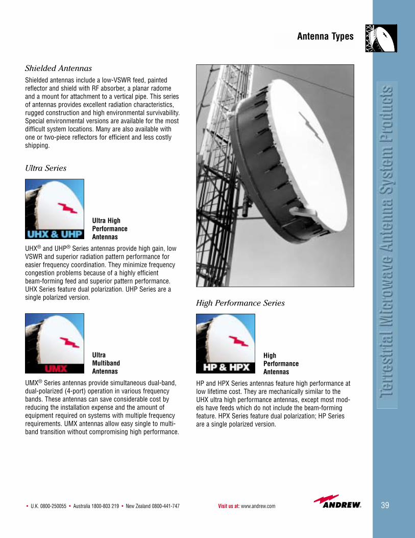
High Performance Series
High Performance Antennas
HP and HPX Series antennas feature high performance atlow lifetime cost. They are mechanically similar to theUHX ultra high performance antennas, except most mod-els have feeds which do not include the beam-forming feature. HPX Series feature dual polarization; HP Seriesare a single polarized version.
Shielded AntennasShielded antennas include a low-VSWR feed, paintedreflector and shield with RF absorber, a planar radomeand a mount for attachment to a vertical pipe. This seriesof antennas provides excellent radiation characteristics,rugged construction and high environmental survivability.Special environmental versions are available for the mostdifficult system locations. Many are also available withone or two-piece reflectors for efficient and less costlyshipping.
Ultra Series
Ultra High Performance Antennas
UHX® and UHP® Series antennas provide high gain, lowVSWR and superior radiation pattern performance foreasier frequency coordination. They minimize frequency congestion problems because of a highly efficient beam-forming feed and superior pattern performance.UHX Series feature dual polarization. UHP Series are asingle polarized version.
Ultra Multiband Antennas
UMX® Series antennas provide simultaneous dual-band, dual-polarized (4-port) operation in various frequencybands. These antennas can save considerable cost byreducing the installation expense and the amount ofequipment required on systems with multiple frequencyrequirements. UMX antennas allow easy single to multi-band transition without compromising high performance.
Antenna Types
Customer Service Center - Call toll-free from: • U.S.A., Canada and Mexico 1-800-255-147940
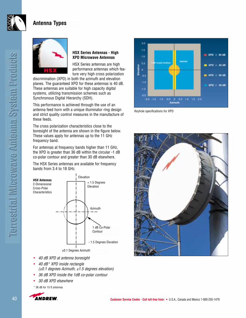
HSX Series Antennas - HighXPD Microwave Antennas
HSX Series antennas are highperformance antennas which fea-ture very high cross polarization
discrimination (XPD) in both the azimuth and elevationplanes. The guaranteed XPD for these antennas is 40 dB.These antennas are suitable for high capacity digital systems, utilizing transmission schemes such asSynchronous Digital Hierarchy (SDH).
This performance is achieved through the use of anantenna feed horn with a unique illuminator ring design and strict quality control measures in the manufacture ofthese feeds.
The cross polarization characteristics close to the boresight of the antenna are shown in the figure below.These values apply for antennas up to the 11 GHz frequency band.
For antennas at frequency bands higher than 11 GHz, the XPD is greater than 36 dB within the circular -1 dB co-polar contour and greater than 30 dB elsewhere.
The HSX Series antennas are available for frequencybands from 3.4 to 18 GHz.
Elevation
+ 1.5 DegreesElevation
Azimuth
- 1.5 Degrees Elevation
±0.1 Degrees Azimuth
HSX Antennas2-Dimensional Cross-Polar Characteristics
• 40 dB XPD at antenna boresight• 40 dB* XPD inside rectangle
(±0.1 degrees Azimuth, ±1.5 degrees elevation)• 36 dB XPD inside the 1dB co-polar contour• 30 dB XPD elsewhere* 36 dB for 15 ft antennas
Keyhole specifications for XPD
Antenna Types
1 dB Co-PolarContour
• U.K. 0800-250055 • Australia 1800-803 219 • New Zealand 0800-441-747 Visit us at: www.andrew.com 41
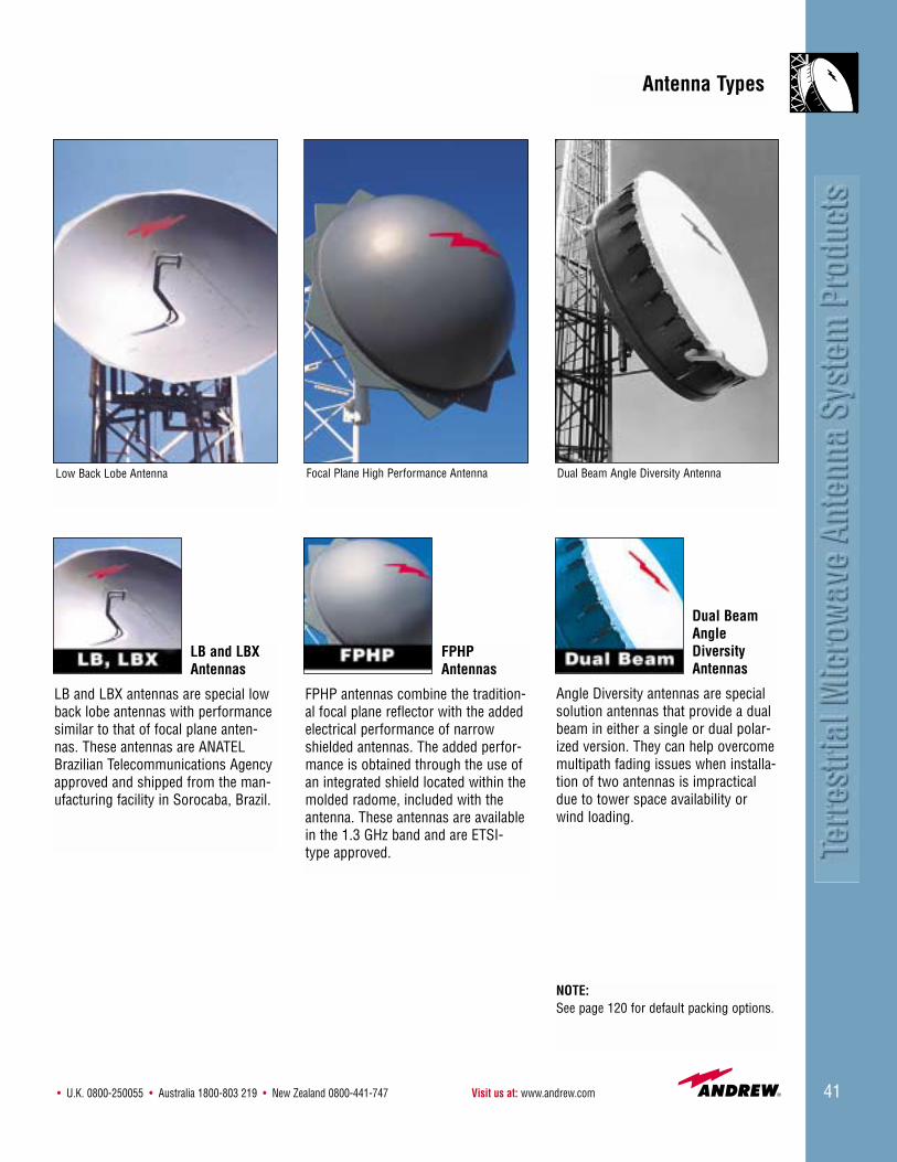
LB and LBXAntennas
LB and LBX antennas are special lowback lobe antennas with performancesimilar to that of focal plane anten-nas. These antennas are ANATELBrazilian Telecommunications Agencyapproved and shipped from the man-ufacturing facility in Sorocaba, Brazil.
FPHPAntennas
FPHP antennas combine the tradition-al focal plane reflector with the addedelectrical performance of narrowshielded antennas. The added perfor-mance is obtained through the use ofan integrated shield located within themolded radome, included with theantenna. These antennas are availablein the 1.3 GHz band and are ETSI-type approved.
Dual BeamAngleDiversityAntennas
Angle Diversity antennas are special solution antennas that provide a dualbeam in either a single or dual polar-ized version. They can help overcomemultipath fading issues when installa-tion of two antennas is impracticaldue to tower space availability orwind loading.
Antenna Types
NOTE:See page 120 for default packing options.
Low Back Lobe Antenna Focal Plane High Performance Antenna Dual Beam Angle Diversity Antenna
Customer Service Center - Call toll-free from: • U.S.A., Canada and Mexico 1-800-255-147942
Antenna Types
NOTE:See page 120 for default packing options.
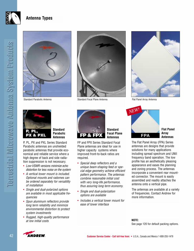
Standard Parabolic Antennas
P, PL, PX and PXL Series StandardParabolic antennas are unshieldedparabolic antennas that provide eco-nomical and reliable service where ahigh degree of back and side radia-tion suppression is not necessary. • Low-VSWR versions minimize echo
distortion for less noise on the system• A vertical tower mount is included.
Optional mounts and radomes canbe ordered separately for versatilityof installation
• Single and dual-polarized optionsare available in most applicable fre-quencies
• Spun aluminum reflectors providelong term reliability and minimizeenvironmental distortion to protectsystem investments
• Rugged, high-quality performanceat low initial costs
Standard Focal Plane Antennas
FP and FPX Series Standard FocalPlane antennas are ideal for use inhigher capacity systems whereimproved front-to-back ratios arerequired.
• Special deep reflectors and aunique beam-shaping feed or spe-cial edge geometry achieve efficientpattern performance. The antennascombine reasonable initial costwith very long-life performance,thus assuring long term economy.
• Single and dual-polarizationoptions are available
• Includes a vertical tower mount forease of tower interface
Flat PanelArrayAntennas
The Flat Panel Array (FPA) Seriesantennas are designs that providesolutions for many applicationsincluding spread spectrum and UNIIfrequency band operation. The lowprofile has an aesthetically pleasingappearance and eases the planningand zoning process. The antennasincorporate a convenient rear mount-ed connector. The mount is easilyassembled and readily attaches theantenna onto a vertical pipe.
The antennas are available at a varietyof frequencies. Contact Andrew formore information.
NEW!
Standard Parabolic Antenna Standard Focal Plane Antenna Flat Panel Array Antenna
FPA
• U.K. 0800-250055 • Australia 1800-803 219 • New Zealand 0800-441-747 Visit us at: www.andrew.com 43
Antenna Types
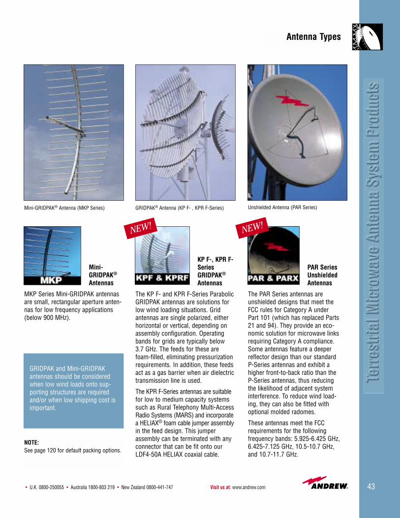
Mini-GRIDPAK®
Antennas
MKP Series Mini-GRIDPAK antennasare small, rectangular aperture anten-nas for low frequency applications(below 900 MHz).
Mini-GRIDPAK® Antenna (MKP Series)
GRIDPAK and Mini-GRIDPAKantennas should be consideredwhen low wind loads onto sup-porting structures are requiredand/or when low shipping cost isimportant.
KP F-, KPR F-SeriesGRIDPAK®
Antennas
The KP F- and KPR F-Series ParabolicGRIDPAK antennas are solutions forlow wind loading situations. Gridantennas are single polarized, eitherhorizontal or vertical, depending onassembly configuration. Operatingbands for grids are typically below3.7 GHz. The feeds for these arefoam-filled, eliminating pressurizationrequirements. In addition, these feedsact as a gas barrier when air dielectrictransmission line is used.
The KPR F-Series antennas are suitablefor low to medium capacity systemssuch as Rural Telephony Multi-AccessRadio Systems (MARS) and incorporatea HELIAX® foam cable jumper assemblyin the feed design. This jumperassembly can be terminated with anyconnector that can be fit onto ourLDF4-50A HELIAX coaxial cable.
GRIDPAK® Antenna (KP F- , KPR F-Series)
NEW!
PAR Series UnshieldedAntennas
The PAR Series antennas areunshielded designs that meet theFCC rules for Category A underPart 101 (which has replaced Parts21 and 94). They provide an eco-nomic solution for microwave linksrequiring Category A compliance.Some antennas feature a deeperreflector design than our standardP-Series antennas and exhibit ahigher front-to-back ratio than theP-Series antennas, thus reducingthe likelihood of adjacent systeminterference. To reduce wind load-ing, they can also be fitted withoptional molded radomes.
These antennas meet the FCCrequirements for the following frequency bands: 5.925-6.425 GHz,6.425-7.125 GHz, 10.5-10.7 GHz,and 10.7-11.7 GHz.
NOTE:See page 120 for default packing options.
NEW!
Unshielded Antenna (PAR Series)
Customer Service Center - Call toll-free from: • U.S.A., Canada and Mexico 1-800-255-147944
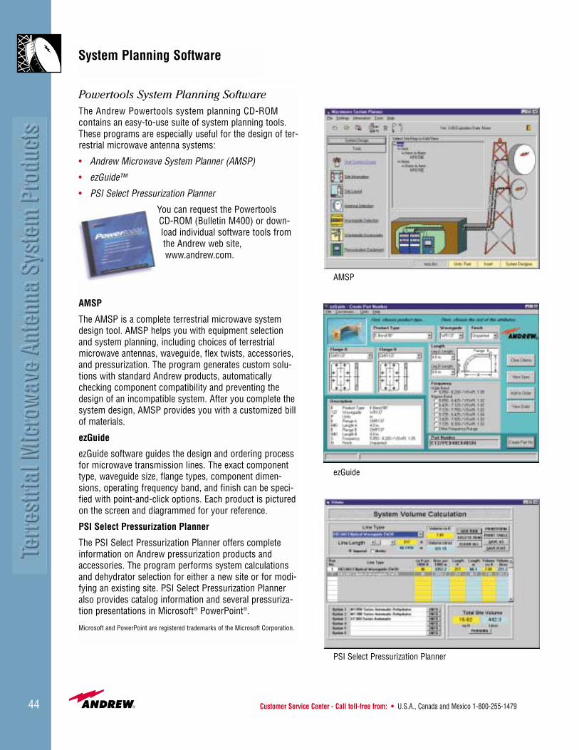
Powertools System Planning SoftwareThe Andrew Powertools system planning CD-ROMcontains an easy-to-use suite of system planning tools.These programs are especially useful for the design of ter-restrial microwave antenna systems:
• Andrew Microwave System Planner (AMSP)
• ezGuide™
• PSI Select Pressurization Planner
You can request the Powertools CD-ROM (Bulletin M400) or down-load individual software tools fromthe Andrew web site,www.andrew.com.
AMSP
The AMSP is a complete terrestrial microwave systemdesign tool. AMSP helps you with equipment selectionand system planning, including choices of terrestrialmicrowave antennas, waveguide, flex twists, accessories,and pressurization. The program generates custom solu-tions with standard Andrew products, automaticallychecking component compatibility and preventing thedesign of an incompatible system. After you complete thesystem design, AMSP provides you with a customized billof materials.
ezGuide
ezGuide software guides the design and ordering processfor microwave transmission lines. The exact componenttype, waveguide size, flange types, component dimen-sions, operating frequency band, and finish can be speci-fied with point-and-click options. Each product is picturedon the screen and diagrammed for your reference.
PSI Select Pressurization Planner
The PSI Select Pressurization Planner offers completeinformation on Andrew pressurization products andaccessories. The program performs system calculationsand dehydrator selection for either a new site or for modi-fying an existing site. PSI Select Pressurization Planneralso provides catalog information and several pressuriza-tion presentations in Microsoft® PowerPoint®.
Microsoft and PowerPoint are registered trademarks of the Microsoft Corporation.
AMSP
ezGuide
PSI Select Pressurization Planner
System Planning Software
• U.K. 0800-250055 • Australia 1800-803 219 • New Zealand 0800-441-747 Visit us at: www.andrew.com 45
Reflectors
Antennas are supplied with either one-piece reflectors ortwo-piece reflectors for on-site assembly. All 2-10 ftreflectors are one-piece; 12 and 15 ft reflectors are two-piece. Split (two-piece) reflectors are available as anoption for 8 and 10 ft antennas. Solid (one-piece) reflec-tors are available as an option for 12 ft antennas. KPSeries GRIDPAK® antennas are supplied completely disas-sembled.
Microwave Antenna Feeds
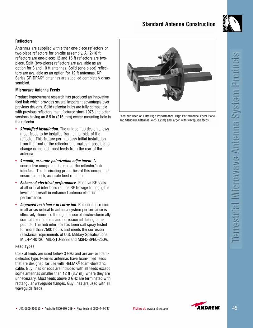
Product improvement research has produced an innovativefeed hub which provides several important advantages overprevious designs. Solid reflector hubs are fully compatiblewith previous reflectors manufactured since 1975 and otherversions having an 8.5 in (216 mm) center mounting hole inthe reflector.
• Simplified installation. The unique hub design allowsmost feeds to be installed from either side of thereflector. This feature permits easy initial installationfrom the front of the reflector and makes it possible tochange or inspect most feeds from the rear of theantenna.
• Smooth, accurate polarization adjustment. A conductive compound is used at the reflector/hubinterface. The lubricating properties of this compoundensure smooth, accurate feed rotation.
• Enhanced electrical performance. Positive RF seals at all critical interfaces reduce RF leakage to negligiblelevels and result in enhanced antenna electrical performance.
• Improved resistance to corrosion. Potential corrosionin all areas critical to antenna system performance iseffectively eliminated through the use of electro-chemicallycompatible materials and corrosion inhibiting com-pounds. The hub interface has been salt spray testedfor more than 7500 hours and meets the corrosionresistance requirements of U.S. Military SpecificationsMIL-F-14072C, MIL-STD-889B and MSFC-SPEC-250A.
Feed Types
Coaxial feeds are used below 3 GHz and are air- or foam-dielectric type. F-series antennas have foam-filled feedsthat are designed for use with HELIAX® foam-dielectriccable. Guy lines or rods are included with all feeds exceptsome antennas smaller than 12 ft (3.7 m), where they areunnecessary. Most feeds above 3 GHz are terminated withrectangular waveguide flanges. Guy lines are used with allwaveguide feeds.
Standard Antenna Construction
Feed hub used on Ultra High Performance, HIgh Performance, Focal Planeand Standard Antennas, 4-ft (1.2 m) and larger, with waveguide feeds.
Customer Service Center - Call toll-free from: • U.S.A., Canada and Mexico 1-800-255-147946
Radomes
Radomes are used to protect microwave antennas againstaccumulation of ice, snow, and dirt and to reduce windloading. All Andrew shielded antennas include a planarradome. Antennas which include a radome are indicatedin the antenna specification tables on pages 116-119.Optional molded radomes, listed on page 118, are avail-able for most other solid reflector, standard unshieldedparabolic antennas.
Radomes for shielded antennas. All Andrew shieldedantennas, except ValuLine® include a flexible planarradome. The radome is stretched across the opening ofthe shield (through tensioning springs) flexing slightly inthe wind to shed ice and snow in most environments.
Two types of flexible planar radomes are used, TEGLAR®
and Hypalon. Hypalon is a rubber coated nylon and is pro-vided with HP and HPX series antennas. TEGLAR is apolymer-coated fiberglass material and is provided withHSX, UHX and UMX type antennas.
In addition, TEGLAR radomes are extremely durable, andexcel in resistance to heat, rain, snow, fungus, ice accu-mulation, corrosive atmosphere and ultraviolet light.Upgrades to TEGLAR on HP and HPX series is optional.
Pre-tensioned radomes. Some high performance antennas are supplied with a pre-tensioned radome. Pre-tensioned radomes are made from TEGLAR® materialbonded to a support ring. They replace the previouslyoffered spring tensioned design.
Radomes for standard antennas. Molded radomes aremanufactured of ABS plastic or fiberglass. They helpreduce tower wind loading and are optional for mostantennas.
Mounts
All microwave antennas are supplied with a vertical towermount. Roof, vertical tilt and horizontal tilt mounts areavailable as options.
Shields
Cylindrical shields, attached to the reflector rim, improvethe radiation pattern performance of parabolic antennas.RF absorbing material is placed at critical locations insidethe shield to reduce RF energy reflections.
Antenna Finish
Standard colors for microwave antennas and radomes arelisted in the table below. Other colors in compliance withU.S. FCC and U.S. FAA regulations or special applicationsare available on request. Unless otherwise specified,radomes supplied with special color antennas will be thestandard color.
For optional TEGLAR radome colors, see page 116.
Microwave Antenna and Radome Standard ColorsDescription Standard Color
Shielded Antennas Gray
Radomes for Shielded Antennas4-15 ft (1.2-4.6 m) White
Standard Antennas Gray
Molded Radomes for Standard Antennas Gray
GRIDPAK® and Mini-GRIDPAK® Antennas Unpainted aluminum
Standard Antenna Construction
• U.K. 0800-250055 • Australia 1800-803 219 • New Zealand 0800-441-747 Visit us at: www.andrew.com 47
Andrew offers the industry’s most comprehensive line ofantennas for point-to-point microwave communication.The extremely wide range of available antennas permitsyou to choose an antenna that is optimized for yourrequirements. Nearly 6000 different configurations areavailable from this catalog. In choosing an antenna, thefollowing basic parameters should be considered:
Operating frequency band. The antennas on pages 51-91are listed in order of ascending operating frequency.Antennas for simultaneous operation in two or morebands are offered on pages 93 and 94.
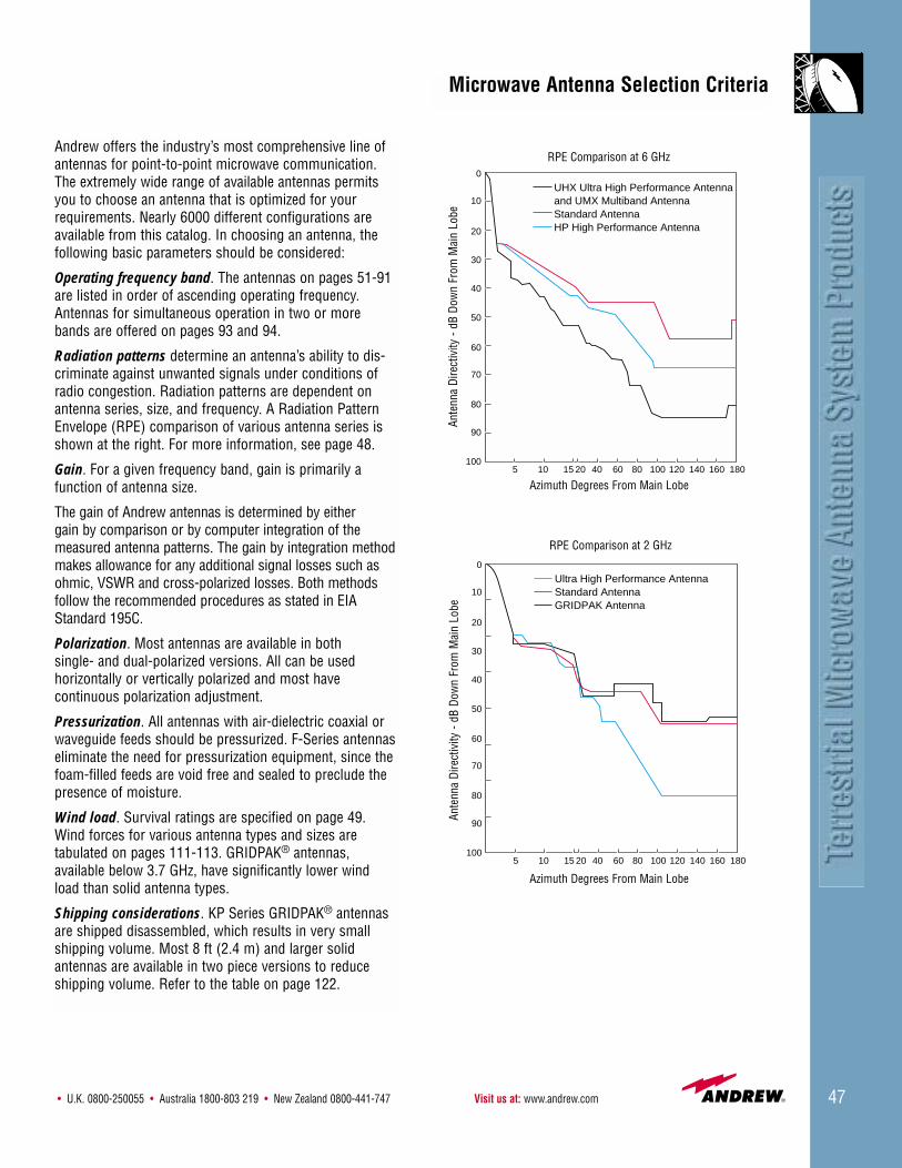
Radiation patterns determine an antenna’s ability to dis-criminate against unwanted signals under conditions ofradio congestion. Radiation patterns are dependent onantenna series, size, and frequency. A Radiation PatternEnvelope (RPE) comparison of various antenna series isshown at the right. For more information, see page 48.
Gain. For a given frequency band, gain is primarily a function of antenna size.
The gain of Andrew antennas is determined by either gain by comparison or by computer integration of the measured antenna patterns. The gain by integration methodmakes allowance for any additional signal losses such asohmic, VSWR and cross-polarized losses. Both methodsfollow the recommended procedures as stated in EIAStandard 195C.
Polarization. Most antennas are available in bothsingle- and dual-polarized versions. All can be used horizontally or vertically polarized and most havecontinuous polarization adjustment.
Pressurization. All antennas with air-dielectric coaxial orwaveguide feeds should be pressurized. F-Series antennaseliminate the need for pressurization equipment, since thefoam-filled feeds are void free and sealed to preclude thepresence of moisture.
Wind load. Survival ratings are specified on page 49.Wind forces for various antenna types and sizes are tabulated on pages 111-113. GRIDPAK® antennas, available below 3.7 GHz, have significantly lower windload than solid antenna types.
Shipping considerations. KP Series GRIDPAK® antennasare shipped disassembled, which results in very smallshipping volume. Most 8 ft (2.4 m) and larger solid antennas are available in two piece versions to reduceshipping volume. Refer to the table on page 122.
Microwave Antenna Selection Criteria
100
90
80
70
60
50
40
30
20
10
0
5 10 15 20 40 60 80 100 120 140 160 180
UHX Ultra High Performance Antennaand UMX Multiband AntennaStandard AntennaHP High Performance Antenna
Azimuth Degrees From Main Lobe
Ante
nna
Dire
ctiv
ity -
dB D
own
From
Mai
n Lo
be
RPE Comparison at 6 GHz
100
90
80
70
60
50
40
30
20
10
0
5 10 15 20 40 60 80 100 120 140 160 180
Ultra High Performance AntennaStandard AntennaGRIDPAK Antenna
RPE Comparison at 2 GHz
Ante
nna
Dire
ctiv
ity -
dB D
own
From
Mai
n Lo
be
Azimuth Degrees From Main Lobe
Customer Service Center - Call toll-free from: • U.S.A., Canada and Mexico 1-800-255-147948
Antenna ElectricalSpecifications
Radiation Pattern EnvelopesRadiation pattern envelopes (RPEs) published by Andrewpresent radiation pattern information in a form that is easyto use for planning radio systems. RPEs are available forall catalog microwave antennas. Copies are on file at theU.S. FCC, Industry Canada, BT, Telecom Australia, FrenchCNET, and many other administrations throughout theworld. U. S. FCC code numbers are assigned to Andrewantennas where applicable. Curves are presented in both rectangular coordinate graph and tabulated digitalformats.
Andrew software, included on the Powertools CD-ROM and downloadable fromwww.andrew.com, allows you to view RPEsfor the antennas listed in the catalog. Seepage 44 for more information.
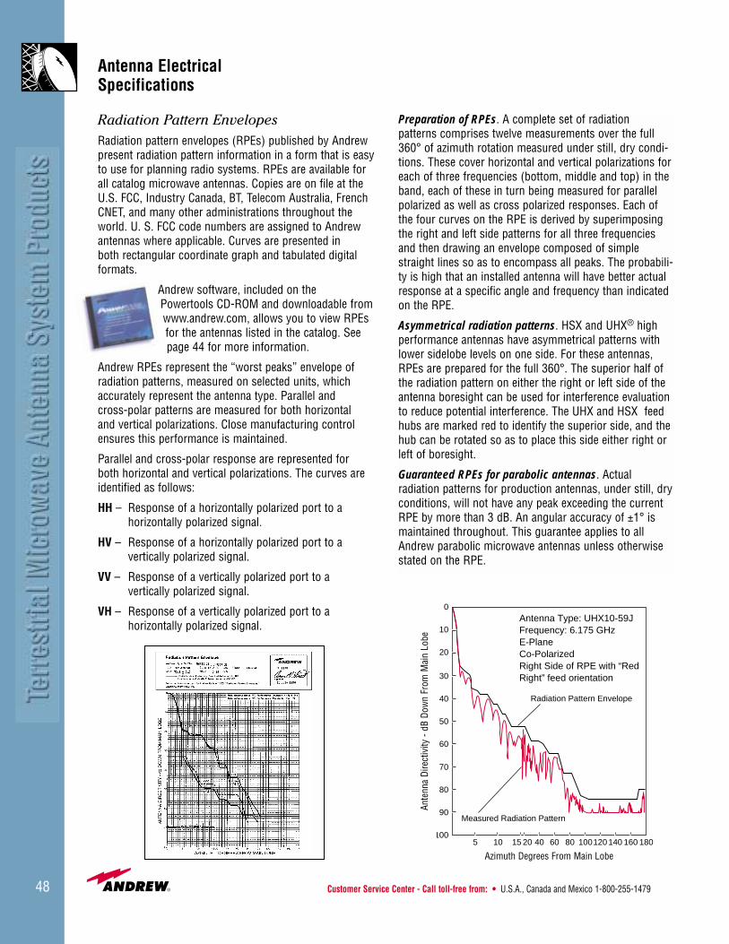
Andrew RPEs represent the “worst peaks” envelope ofradiation patterns, measured on selected units, whichaccurately represent the antenna type. Parallel and cross-polar patterns are measured for both horizontal and vertical polarizations. Close manufacturing controlensures this performance is maintained.
Parallel and cross-polar response are represented for both horizontal and vertical polarizations. The curves areidentified as follows:
HH – Response of a horizontally polarized port to a horizontally polarized signal.
HV – Response of a horizontally polarized port to a vertically polarized signal.
VV – Response of a vertically polarized port to a vertically polarized signal.
VH – Response of a vertically polarized port to a horizontally polarized signal.
Preparation of RPEs. A complete set of radiation patterns comprises twelve measurements over the full360° of azimuth rotation measured under still, dry condi-tions. These cover horizontal and vertical polarizations foreach of three frequencies (bottom, middle and top) in theband, each of these in turn being measured for parallelpolarized as well as cross polarized responses. Each ofthe four curves on the RPE is derived by superimposingthe right and left side patterns for all three frequenciesand then drawing an envelope composed of simplestraight lines so as to encompass all peaks. The probabili-ty is high that an installed antenna will have better actualresponse at a specific angle and frequency than indicatedon the RPE.
Asymmetrical radiation patterns. HSX and UHX® highperformance antennas have asymmetrical patterns withlower sidelobe levels on one side. For these antennas,RPEs are prepared for the full 360°. The superior half ofthe radiation pattern on either the right or left side of theantenna boresight can be used for interference evaluationto reduce potential interference. The UHX and HSX feedhubs are marked red to identify the superior side, and thehub can be rotated so as to place this side either right orleft of boresight.
Guaranteed RPEs for parabolic antennas. Actual radiation patterns for production antennas, under still, dryconditions, will not have any peak exceeding the currentRPE by more than 3 dB. An angular accuracy of ±1° ismaintained throughout. This guarantee applies to allAndrew parabolic microwave antennas unless otherwisestated on the RPE.
100
90
80
70
60
50
40
30
20
10
0
5 10 15 20 40 60 80 100120 140 160 180
Radiation Pattern Envelope
Measured Radiation Pattern
Antenna Type: UHX10-59JFrequency: 6.175 GHzE-PlaneCo-PolarizedRight Side of RPE with “RedRight” feed orientation
Azimuth Degrees From Main Lobe
Ante
nna
Dire
ctiv
ity -
dB D
own
From
Mai
n Lo
be
• U.K. 0800-250055 • Australia 1800-803 219 • New Zealand 0800-441-747 Visit us at: www.andrew.com 49
Wind Survival and Deflection CharacteristicsSurvival Ratings Max. Deflection in 70 mph
Antenna Types Wind Velocity mph (km/h) Radial Ice, in (mm) (110 km/h) Wind, degrees
Standard AntennasWithout Radome 125 (200) 1 (25) 0.1With Standard Radome 125 (200) 1 (25) 0.1
UHX®, UMX®, UHP, HSX and HP Antennas 125 (200) 1 (25) 0.1
GRIDPAK® Antennas 125 (200) – –
Electrical DefinitionsThe following terms describe the electrical characteristicsfor Andrew microwave antennas. All rated electrical char-acteristics listed in the tables are guaranteed to be withinthe tolerances stated below. Factory measurements ofthese electrical characteristics are made under still, dry conditions using state-of-the art equipment and techniques ensuring high accuracy.
Frequency refers to the operating frequency band. Thesebands correspond with CCIR recommendations or com-mon allocations used throughout the world. It is usuallypossible to tune antennas for slightly different frequencyranges while retaining the same electrical characteristics.Other ranges can be accommodated on special order.
VSWR. Maximum, is the guaranteed peak Voltage-Standing-Wave-Ratio within the operating band.
Isolation between inputs of single-band, dual-polarizedantennas is 35 dB minimum unless otherwise specified.
Gain is stated in dBi (decibels over an isotropic radiator)at three frequencies: bottom, middle and top of band.Manufacturing tolerance for antenna gain is 0.2 dB unless otherwise specified. In the case of two-port, dual-polarized antennas, the specified gain refers to the average gain of the two ports, the gain of each port differing from the average gain by not more than 0.3 dB.
Front-to-back ratio in decibels. Denotes highest radiationrelative to the main beam, at 180° ±40°, across the band.Production antennas do not exceed rated values by morethan 2 dB unless stated otherwise.
Half-power beamwidth is the nominal total width of themain beam at the -3 dB points.
Cross-polarization discrimination, in dB, is the differencebetween the peak of the co-polarized main beam and themaximum cross-polarized signal over an angle twice the 3 dB beamwidth of the co-polarized main beam.
Power rating. All microwave antenna feeds are rated at150 watts.
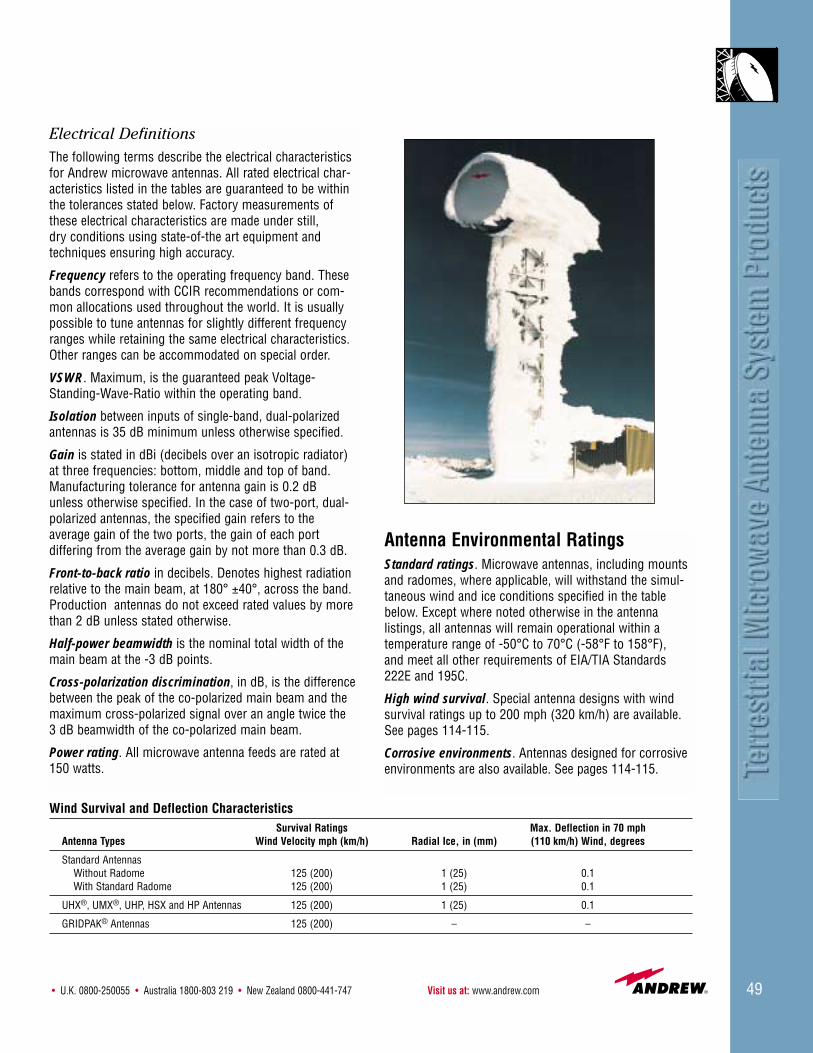
Antenna Environmental RatingsStandard ratings. Microwave antennas, including mountsand radomes, where applicable, will withstand the simul-taneous wind and ice conditions specified in the tablebelow. Except where noted otherwise in the antenna listings, all antennas will remain operational within a temperature range of -50°C to 70°C (-58°F to 158°F), and meet all other requirements of EIA/TIA Standards222E and 195C.
High wind survival. Special antenna designs with windsurvival ratings up to 200 mph (320 km/h) are available.See pages 114-115.
Corrosive environments. Antennas designed for corrosiveenvironments are also available. See pages 114-115.
Customer Service Center - Call toll-free from: • U.S.A., Canada and Mexico 1-800-255-147950
Antenna Specifications and Ordering Information
Antenna Ordering Tables
Our line of terrestrial microwave antennas is presented inthe tables on pages 51-94. The tables are arranged byoperating frequency band, in ascending order. Within thetables, antennas are grouped by antenna type, and bydiameter.
Basic Antenna
The type numbers listed in the tables define the basicantenna, less options and accessories. The tables alsoinclude RPE numbers and define important electrical performance parameters of the antennas.
All of the antennas in this section include a feed, reflector and vertical tower mount. Refer to the “AntennaTypes” and “Antenna Construction” sections, pages 39-46for details.
Antenna Inputs
Connector and flange options for each antenna are listedwithin the ordering tables. Other flanges, available asoptions, may effect VSWR performance where noted.Contact Andrew for more details.
Flange options are discussed in detail on pages 114 and 115.
Radomes
All shielded antennas include either a TEGLAR® long-liferadome, a Hypalon coated nylon radome or a moldedthermoplastic planar radome, as specified in the tables.The TEGLAR long-life radome is optional for antennaswhich are normally supplied with the Hypalon radome.
Molded radomes are also available as an option for most standard (non-shielded, solid reflector) antennas.Radomes are not applicable for any grid types.
Radomes are discussed in detail on pages 116-119.
Regulatory Information
Any regulatory compliance pertaining to an antenna isnoted in its catalog entry.
Antenna Options
Andrew offers a variety of antenna options which allowyou to choose additional features or change features fromthe basic antenna offerings. Options are described indetail on pages 114-122.
• Input connectors and flanges
• Antenna colors
• Radomes
• Radome colors
• High wind survival antennas
• Corrosive environment antennas
• Packing type
• Packing quantity
• Reflector type
• Special purpose mounts
Accessories
In addition to the above options, Andrew offers the following accessories to enhance your antenna selection.Accessories are described in detail on pages 119, 123-126.
• Edge protection kits for TEGLAR® radome
• Port termination loads
• Additional side or bottom mounting struts
Replacement Components
Contact Andrew for information on replacement components.
• Reflectors
• Feeds
• Radomes and radome clip kits (page 119)
• Shield absorber kits
• Major hardware kits
• Mounts (page 96)
• Universal guy wire kits
• Shields
• Struts (page 96)
• U.K. 0800-250055 • Australia 1800-803 219 • New Zealand 0800-441-747 Visit us at: www.andrew.com 51
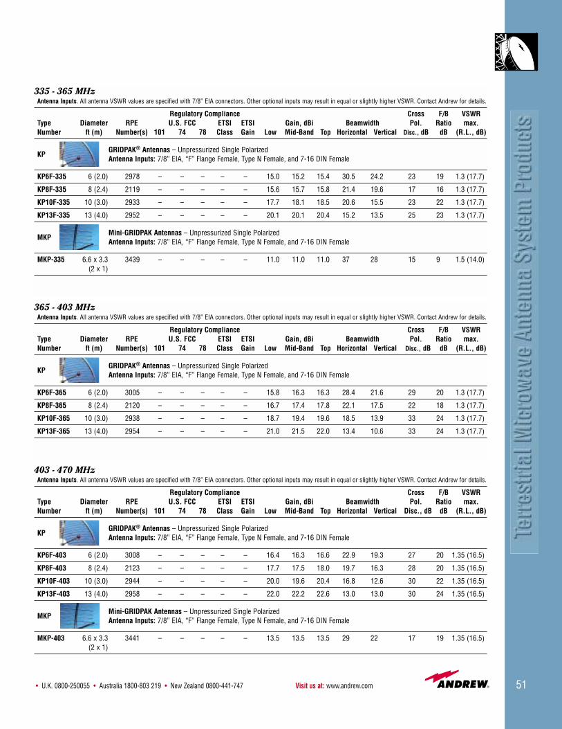
335 - 365 MHzAntenna Inputs. All antenna VSWR values are specified with 7/8” EIA connectors. Other optional inputs may result in equal or slightly higher VSWR. Contact Andrew for details.
Regulatory Compliance Cross F/B VSWRType Diameter RPE U.S. FCC ETSI ETSI Gain, dBi Beamwidth Pol. Ratio max.Number ft (m) Number(s) 101 74 78 Class Gain Low Mid-Band Top Horizontal Vertical Disc., dB dB (R.L., dB)
KPGRIDPAK® Antennas – Unpressurized Single PolarizedAntenna Inputs: 7/8” EIA, “F” Flange Female, Type N Female, and 7-16 DIN Female
KP6F-335 6 (2.0) 2978 – – – – – 15.0 15.2 15.4 30.5 24.2 23 19 1.3 (17.7)
KP8F-335 8 (2.4) 2119 – – – – – 15.6 15.7 15.8 21.4 19.6 17 16 1.3 (17.7)
KP10F-335 10 (3.0) 2933 – – – – – 17.7 18.1 18.5 20.6 15.5 23 22 1.3 (17.7)
KP13F-335 13 (4.0) 2952 – – – – – 20.1 20.1 20.4 15.2 13.5 25 23 1.3 (17.7)
MKPMini-GRIDPAK Antennas – Unpressurized Single PolarizedAntenna Inputs: 7/8” EIA, “F” Flange Female, Type N Female, and 7-16 DIN Female
MKP-335 6.6 x 3.3 3439 – – – – – 11.0 11.0 11.0 37 28 15 9 1.5 (14.0)(2 x 1)
365 - 403 MHzAntenna Inputs. All antenna VSWR values are specified with 7/8” EIA connectors. Other optional inputs may result in equal or slightly higher VSWR. Contact Andrew for details.
Regulatory Compliance Cross F/B VSWRType Diameter RPE U.S. FCC ETSI ETSI Gain, dBi Beamwidth Pol. Ratio max.Number ft (m) Number(s) 101 74 78 Class Gain Low Mid-Band Top Horizontal Vertical Disc., dB dB (R.L., dB)
KPGRIDPAK® Antennas – Unpressurized Single PolarizedAntenna Inputs: 7/8” EIA, “F” Flange Female, Type N Female, and 7-16 DIN Female
KP6F-365 6 (2.0) 3005 – – – – – 15.8 16.3 16.3 28.4 21.6 29 20 1.3 (17.7)
KP8F-365 8 (2.4) 2120 – – – – – 16.7 17.4 17.8 22.1 17.5 22 18 1.3 (17.7)
KP10F-365 10 (3.0) 2938 – – – – – 18.7 19.4 19.6 18.5 13.9 33 24 1.3 (17.7)
KP13F-365 13 (4.0) 2954 – – – – – 21.0 21.5 22.0 13.4 10.6 33 24 1.3 (17.7)
403 - 470 MHzAntenna Inputs. All antenna VSWR values are specified with 7/8” EIA connectors. Other optional inputs may result in equal or slightly higher VSWR. Contact Andrew for details.
Regulatory Compliance Cross F/B VSWRType Diameter RPE U.S. FCC ETSI ETSI Gain, dBi Beamwidth Pol. Ratio max.Number ft (m) Number(s) 101 74 78 Class Gain Low Mid-Band Top Horizontal Vertical Disc., dB dB (R.L., dB)
KPGRIDPAK® Antennas – Unpressurized Single PolarizedAntenna Inputs: 7/8” EIA, “F” Flange Female, Type N Female, and 7-16 DIN Female
KP6F-403 6 (2.0) 3008 – – – – – 16.4 16.3 16.6 22.9 19.3 27 20 1.35 (16.5)
KP8F-403 8 (2.4) 2123 – – – – – 17.7 17.5 18.0 19.7 16.3 28 20 1.35 (16.5)
KP10F-403 10 (3.0) 2944 – – – – – 20.0 19.6 20.4 16.8 12.6 30 22 1.35 (16.5)
KP13F-403 13 (4.0) 2958 – – – – – 22.0 22.2 22.6 13.0 13.0 30 24 1.35 (16.5)
MKPMini-GRIDPAK Antennas – Unpressurized Single PolarizedAntenna Inputs: 7/8” EIA, “F” Flange Female, Type N Female, and 7-16 DIN Female
MKP-403 6.6 x 3.3 3441 – – – – – 13.5 13.5 13.5 29 22 17 19 1.35 (16.5)(2 x 1)
Customer Service Center - Call toll-free from: • U.S.A., Canada and Mexico 1-800-255-147952
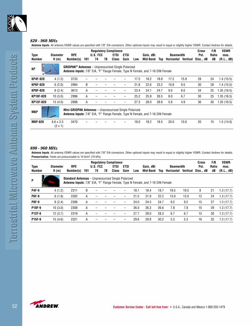
820 - 960 MHzAntenna Inputs. All antenna VSWR values are specified with 7/8” EIA connectors. Other optional inputs may result in equal or slightly higher VSWR. Contact Andrew for details.
Regulatory Compliance Cross F/B VSWRType Diameter RPE U.S. FCC ETSI ETSI Gain, dBi Beamwidth Pol. Ratio max.Number ft (m) Number(s) 101 74 78 Class Gain Low Mid-Band Top Horizontal Vertical Disc., dB dB (R.L., dB)
KPGRIDPAK® Antennas – Unpressurized Single PolarizedAntenna Inputs: 7/8” EIA, “F” Flange Female, Type N Female, and 7-16 DIN Female
KP4F-820 4 (1.2) 3733 – – – – – 17.5 18.2 18.8 17.2 15.9 28 24 1.4 (15.5)
KP6F-820 6 (2.0) 2994 B – – – – 21.8 22.6 23.2 10.8 9.5 30 28 1.4 (15.5)
KP8F-820 8 (2.4) 3613 A – – – – 23.4 24.1 24.7 9.0 8.0 34 25 1.35 (16.5)
KP10F-820 10 (3.0) 2996 A – – – – 25.2 25.9 26.5 8.0 6.7 30 25 1.35 (16.5)
KP13F-820 13 (4.0) 2998 A – – – – 27.3 28.0 28.6 5.8 4.9 36 30 1.35 (16.5)
MKPMini-GRIDPAK Antennas – Unpressurized Single PolarizedAntenna Inputs: 7/8” EIA, “F” Flange Female, Type N Female, and 7-16 DIN Female
MKP-820 6.6 x 3.3 3470 – – – – – 18.0 18.2 18.5 20.0 10.0 20 15 1.5 (14.0)(2 x 1)
890 - 960 MHzAntenna Inputs. All antenna VSWR values are specified with 7/8” EIA connectors. Other optional inputs may result in equal or slightly higher VSWR. Contact Andrew for details.Pressurization. Feeds are pressurizable to 10 lb/in2 (70 kPa).
Regulatory Compliance Cross F/B VSWRType Diameter RPE U.S. FCC ETSI ETSI Gain, dBi Beamwidth Pol. Ratio max.Number ft (m) Number(s) 101 74 78 Class Gain Low Mid-Band Top Horizontal Vertical Disc., dB dB (R.L., dB)
P Standard Antennas – Unpressurized Single PolarizedAntenna Inputs: 7/8” EIA, “F” Flange Female, Type N Female, and 7-16 DIN Female
P4F-9 4 (1.2) 2311 B – – – – 18.1 18.4 18.7 19.5 19.5 8 21 1.3 (17.7)
P6F-9 6 (1.8) 2302 A – – – – 21.5 21.9 22.2 13.0 13.0 12 24 1.3 (17.7)
P8F-9 8 (2.4) 2306 A – – – – 24.0 24.3 24.7 9.2 9.2 15 27 1.3 (17.7)
P10F-9 10 (3.0) 2308 A – – – – 26.0 26.3 26.6 7.8 7.8 15 29 1.3 (17.7)
P12F-9 12 (3.7) 2319 A – – – – 27.7 28.0 28.3 6.7 6.7 15 30 1.3 (17.7)
P15F-9 15 (4.6) 2321 A – – – – 29.6 29.9 30.2 5.3 5.3 16 32 1.3 (17.7)
• U.K. 0800-250055 • Australia 1800-803 219 • New Zealand 0800-441-747 Visit us at: www.andrew.com 53
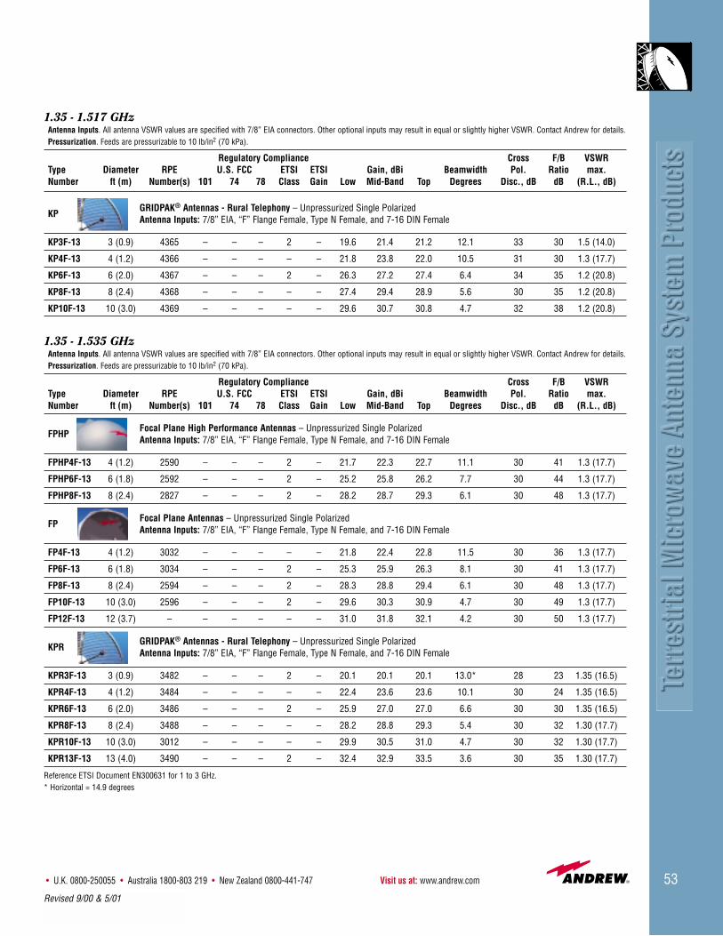
1.35 - 1.517 GHzAntenna Inputs. All antenna VSWR values are specified with 7/8” EIA connectors. Other optional inputs may result in equal or slightly higher VSWR. Contact Andrew for details.Pressurization. Feeds are pressurizable to 10 lb/in2 (70 kPa).
Regulatory Compliance Cross F/B VSWRType Diameter RPE U.S. FCC ETSI ETSI Gain, dBi Beamwidth Pol. Ratio max.Number ft (m) Number(s) 101 74 78 Class Gain Low Mid-Band Top Degrees Disc., dB dB (R.L., dB)
KPGRIDPAK® Antennas - Rural Telephony – Unpressurized Single PolarizedAntenna Inputs: 7/8” EIA, “F” Flange Female, Type N Female, and 7-16 DIN Female
KP3F-13 3 (0.9) 4365 – – – 2 – 19.6 21.4 21.2 12.1 33 30 1.5 (14.0)
KP4F-13 4 (1.2) 4366 – – – – – 21.8 23.8 22.0 10.5 31 30 1.3 (17.7)
KP6F-13 6 (2.0) 4367 – – – 2 – 26.3 27.2 27.4 6.4 34 35 1.2 (20.8)
KP8F-13 8 (2.4) 4368 – – – – – 27.4 29.4 28.9 5.6 30 35 1.2 (20.8)
KP10F-13 10 (3.0) 4369 – – – – – 29.6 30.7 30.8 4.7 32 38 1.2 (20.8)
1.35 - 1.535 GHzAntenna Inputs. All antenna VSWR values are specified with 7/8” EIA connectors. Other optional inputs may result in equal or slightly higher VSWR. Contact Andrew for details.Pressurization. Feeds are pressurizable to 10 lb/in2 (70 kPa).
Regulatory Compliance Cross F/B VSWRType Diameter RPE U.S. FCC ETSI ETSI Gain, dBi Beamwidth Pol. Ratio max.Number ft (m) Number(s) 101 74 78 Class Gain Low Mid-Band Top Degrees Disc., dB dB (R.L., dB)
FPHPFocal Plane High Performance Antennas – Unpressurized Single PolarizedAntenna Inputs: 7/8” EIA, “F” Flange Female, Type N Female, and 7-16 DIN Female
FPHP4F-13 4 (1.2) 2590 – – – 2 – 21.7 22.3 22.7 11.1 30 41 1.3 (17.7)
FPHP6F-13 6 (1.8) 2592 – – – 2 – 25.2 25.8 26.2 7.7 30 44 1.3 (17.7)
FPHP8F-13 8 (2.4) 2827 – – – 2 – 28.2 28.7 29.3 6.1 30 48 1.3 (17.7)
FPFocal Plane Antennas – Unpressurized Single PolarizedAntenna Inputs: 7/8” EIA, “F” Flange Female, Type N Female, and 7-16 DIN Female
FP4F-13 4 (1.2) 3032 – – – – – 21.8 22.4 22.8 11.5 30 36 1.3 (17.7)
FP6F-13 6 (1.8) 3034 – – – 2 – 25.3 25.9 26.3 8.1 30 41 1.3 (17.7)
FP8F-13 8 (2.4) 2594 – – – 2 – 28.3 28.8 29.4 6.1 30 48 1.3 (17.7)
FP10F-13 10 (3.0) 2596 – – – 2 – 29.6 30.3 30.9 4.7 30 49 1.3 (17.7)
FP12F-13 12 (3.7) – – – – – – 31.0 31.8 32.1 4.2 30 50 1.3 (17.7)
KPRGRIDPAK® Antennas - Rural Telephony – Unpressurized Single PolarizedAntenna Inputs: 7/8” EIA, “F” Flange Female, Type N Female, and 7-16 DIN Female
KPR3F-13 3 (0.9) 3482 – – – 2 – 20.1 20.1 20.1 13.0* 28 23 1.35 (16.5)
KPR4F-13 4 (1.2) 3484 – – – – – 22.4 23.6 23.6 10.1 30 24 1.35 (16.5)
KPR6F-13 6 (2.0) 3486 – – – 2 – 25.9 27.0 27.0 6.6 30 30 1.35 (16.5)
KPR8F-13 8 (2.4) 3488 – – – – – 28.2 28.8 29.3 5.4 30 32 1.30 (17.7)
KPR10F-13 10 (3.0) 3012 – – – – – 29.9 30.5 31.0 4.7 30 32 1.30 (17.7)
KPR13F-13 13 (4.0) 3490 – – – 2 – 32.4 32.9 33.5 3.6 30 35 1.30 (17.7)
Reference ETSI Document EN300631 for 1 to 3 GHz.* Horizontal = 14.9 degrees
Revised 9/00 & 5/01
Customer Service Center - Call toll-free from: • U.S.A., Canada and Mexico 1-800-255-147954
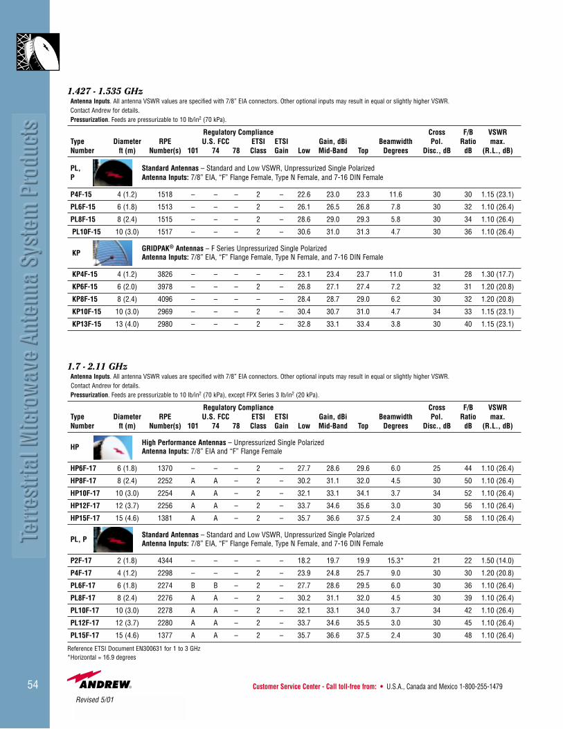
1.427 - 1.535 GHzAntenna Inputs. All antenna VSWR values are specified with 7/8” EIA connectors. Other optional inputs may result in equal or slightly higher VSWR. Contact Andrew for details.Pressurization. Feeds are pressurizable to 10 lb/in2 (70 kPa).
Regulatory Compliance Cross F/B VSWRType Diameter RPE U.S. FCC ETSI ETSI Gain, dBi Beamwidth Pol. Ratio max.Number ft (m) Number(s) 101 74 78 Class Gain Low Mid-Band Top Degrees Disc., dB dB (R.L., dB)
PL, Standard Antennas – Standard and Low VSWR, Unpressurized Single PolarizedP Antenna Inputs: 7/8” EIA, “F” Flange Female, Type N Female, and 7-16 DIN Female
P4F-15 4 (1.2) 1518 – – – 2 – 22.6 23.0 23.3 11.6 30 30 1.15 (23.1)
PL6F-15 6 (1.8) 1513 – – – 2 – 26.1 26.5 26.8 7.8 30 32 1.10 (26.4)
PL8F-15 8 (2.4) 1515 – – – 2 – 28.6 29.0 29.3 5.8 30 34 1.10 (26.4)
PL10F-15 10 (3.0) 1517 – – – 2 – 30.6 31.0 31.3 4.7 30 36 1.10 (26.4)
KPGRIDPAK® Antennas – F Series Unpressurized Single PolarizedAntenna Inputs: 7/8” EIA, “F” Flange Female, Type N Female, and 7-16 DIN Female
KP4F-15 4 (1.2) 3826 – – – – – 23.1 23.4 23.7 11.0 31 28 1.30 (17.7)
KP6F-15 6 (2.0) 3978 – – – 2 – 26.8 27.1 27.4 7.2 32 31 1.20 (20.8)
KP8F-15 8 (2.4) 4096 – – – – – 28.4 28.7 29.0 6.2 30 32 1.20 (20.8)
KP10F-15 10 (3.0) 2969 – – – 2 – 30.4 30.7 31.0 4.7 34 33 1.15 (23.1)
KP13F-15 13 (4.0) 2980 – – – 2 – 32.8 33.1 33.4 3.8 30 40 1.15 (23.1)
1.7 - 2.11 GHzAntenna Inputs. All antenna VSWR values are specified with 7/8” EIA connectors. Other optional inputs may result in equal or slightly higher VSWR. Contact Andrew for details.Pressurization. Feeds are pressurizable to 10 lb/in2 (70 kPa), except FPX Series 3 lb/in2 (20 kPa).
Regulatory Compliance Cross F/B VSWRType Diameter RPE U.S. FCC ETSI ETSI Gain, dBi Beamwidth Pol. Ratio max.Number ft (m) Number(s) 101 74 78 Class Gain Low Mid-Band Top Degrees Disc., dB dB (R.L., dB)
HPHigh Performance Antennas – Unpressurized Single PolarizedAntenna Inputs: 7/8” EIA and “F” Flange Female
HP6F-17 6 (1.8) 1370 – – – 2 – 27.7 28.6 29.6 6.0 25 44 1.10 (26.4)
HP8F-17 8 (2.4) 2252 A A – 2 – 30.2 31.1 32.0 4.5 30 50 1.10 (26.4)
HP10F-17 10 (3.0) 2254 A A – 2 – 32.1 33.1 34.1 3.7 34 52 1.10 (26.4)
HP12F-17 12 (3.7) 2256 A A – 2 – 33.7 34.6 35.6 3.0 30 56 1.10 (26.4)
HP15F-17 15 (4.6) 1381 A A – 2 – 35.7 36.6 37.5 2.4 30 58 1.10 (26.4)
PL, PStandard Antennas – Standard and Low VSWR, Unpressurized Single PolarizedAntenna Inputs: 7/8” EIA, “F” Flange Female, Type N Female, and 7-16 DIN Female
P2F-17 2 (1.8) 4344 – – – – – 18.2 19.7 19.9 15.3* 21 22 1.50 (14.0)
P4F-17 4 (1.2) 2298 – – – 2 – 23.9 24.8 25.7 9.0 30 30 1.20 (20.8)
PL6F-17 6 (1.8) 2274 B B – 2 – 27.7 28.6 29.5 6.0 30 36 1.10 (26.4)
PL8F-17 8 (2.4) 2276 A A – 2 – 30.2 31.1 32.0 4.5 30 39 1.10 (26.4)
PL10F-17 10 (3.0) 2278 A A – 2 – 32.1 33.1 34.0 3.7 34 42 1.10 (26.4)
PL12F-17 12 (3.7) 2280 A A – 2 – 33.7 34.6 35.5 3.0 30 45 1.10 (26.4)
PL15F-17 15 (4.6) 1377 A A – 2 – 35.7 36.6 37.5 2.4 30 48 1.10 (26.4)
Reference ETSI Document EN300631 for 1 to 3 GHz*Horizontal = 16.9 degrees
Revised 5/01
• U.K. 0800-250055 • Australia 1800-803 219 • New Zealand 0800-441-747 Visit us at: www.andrew.com 55
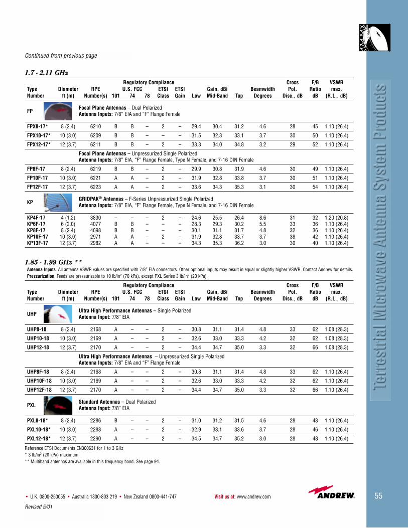
1.7 - 2.11 GHzRegulatory Compliance Cross F/B VSWR
Type Diameter RPE U.S. FCC ETSI ETSI Gain, dBi Beamwidth Pol. Ratio max.Number ft (m) Number(s) 101 74 78 Class Gain Low Mid-Band Top Degrees Disc., dB dB (R.L., dB)
FPFocal Plane Antennas – Dual PolarizedAntenna Inputs: 7/8” EIA and “F” Flange Female
FPX8-17* 8 (2.4) 6210 B B – 2 – 29.4 30.4 31.2 4.6 28 45 1.10 (26.4)
FPX10-17* 10 (3.0) 6209 B B – – – 31.5 32.3 33.1 3.7 30 50 1.10 (26.4)
FPX12-17* 12 (3.7) 6211 B B – 2 – 33.3 34.0 34.8 3.2 29 52 1.10 (26.4)
Focal Plane Antennas – Unpressurized Single PolarizedAntenna Inputs: 7/8” EIA, “F” Flange Female, Type N Female, and 7-16 DIN Female
FP8F-17 8 (2.4) 6219 B B – 2 – 29.9 30.8 31.9 4.6 30 49 1.10 (26.4)
FP10F-17 10 (3.0) 6221 A A – 2 – 31.9 32.8 33.8 3.7 30 51 1.10 (26.4)
FP12F-17 12 (3.7) 6223 A A – 2 – 33.6 34.3 35.3 3.1 30 54 1.10 (26.4)
KPGRIDPAK® Antennas – F-Series Unpressurized Single PolarizedAntenna Inputs: 7/8” EIA, “F” Flange Female, Type N Female, and 7-16 DIN Female
KP4F-17 4 (1.2) 3830 – – – 2 – 24.6 25.5 26.4 8.6 31 32 1.20 (20.8)KP6F-17 6 (2.0) 4077 B B – – – 28.3 29.3 30.2 5.5 33 36 1.10 (26.4)KP8F-17 8 (2.4) 4098 B B – – – 30.1 31.1 31.7 4.8 32 36 1.10 (26.4)KP10F-17 10 (3.0) 2971 A A – 2 – 31.9 32.8 33.7 3.7 38 42 1.10 (26.4)KP13F-17 12 (3.7) 2982 A A – – – 34.3 35.3 36.2 3.0 30 40 1.10 (26.4)
Continued from previous page
1.85 - 1.99 GHz **Antenna Inputs. All antenna VSWR values are specified with 7/8” EIA connectors. Other optional inputs may result in equal or slightly higher VSWR. Contact Andrew for details.Pressurization. Feeds are pressurizable to 10 lb/in2 (70 kPa), except PXL Series 3 lb/in2 (20 kPa).
Regulatory Compliance Cross F/B VSWRType Diameter RPE U.S. FCC ETSI ETSI Gain, dBi Beamwidth Pol. Ratio max.Number ft (m) Number(s) 101 74 78 Class Gain Low Mid-Band Top Degrees Disc., dB dB (R.L., dB)
UHPUltra High Performance Antennas – Single PolarizedAntenna Input: 7/8” EIA
UHP8-18 8 (2.4) 2168 A – – 2 – 30.8 31.1 31.4 4.8 33 62 1.08 (28.3)
UHP10-18 10 (3.0) 2169 A – – 2 – 32.6 33.0 33.3 4.2 32 62 1.08 (28.3)
UHP12-18 12 (3.7) 2170 A – – 2 – 34.4 34.7 35.0 3.3 32 66 1.08 (28.3)
Ultra High Performance Antennas – Unpressurized Single PolarizedAntenna Inputs: 7/8” EIA and “F” Flange Female
UHP8F-18 8 (2.4) 2168 A – – 2 – 30.8 31.1 31.4 4.8 33 62 1.10 (26.4)
UHP10F-18 10 (3.0) 2169 A – – 2 – 32.6 33.0 33.3 4.2 32 62 1.10 (26.4)
UHP12F-18 12 (3.7) 2170 A – – 2 – 34.4 34.7 35.0 3.3 32 66 1.10 (26.4)
PXLStandard Antennas – Dual PolarizedAntenna Input: 7/8” EIA
PXL8-18* 8 (2.4) 2286 B – – 2 – 31.0 31.2 31.5 4.6 28 43 1.10 (26.4)
PXL10-18* 10 (3.0) 2288 A – – 2 – 32.9 33.1 33.6 3.7 28 46 1.10 (26.4)
PXL12-18* 12 (3.7) 2290 A – – 2 – 34.5 34.7 35.2 3.0 28 48 1.10 (26.4)
Reference ETSI Documents EN300631 for 1 to 3 GHz* 3 lb/in2 (20 kPa) maximum ** Multiband antennas are available in this frequency band. See page 94.
Revised 5/01
Customer Service Center - Call toll-free from: • U.S.A., Canada and Mexico 1-800-255-147956
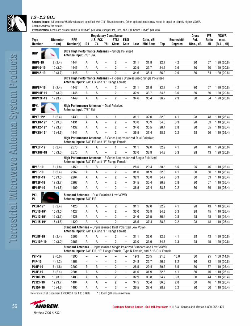
1.9 - 2.3 GHzAntenna Inputs. All antenna VSWR values are specified with 7/8” EIA connectors. Other optional inputs may result in equal or slightly higher VSWR. Contact Andrew for details.Pressurization. Feeds are pressurizable to 10 lb/in2 (70 kPa), except HPX, FPX, and PXL Series 3 lb/in2 (20 kPa).
Regulatory Compliance Cross F/B VSWRType Diameter RPE U.S. FCC ETSI ETSI Gain, dBi Beamwidth Pol. Ratio max.Number ft (m) Number(s) 101 74 78 Class Gain Low Mid-Band Top Degrees Disc., dB dB (R.L., dB)
UHPUltra High Performance Antennas – Single PolarizedAntenna Input: 7/8” EIA
UHP8-19 8 (2.4) 1444 A A – 2 – 31.1 31.9 32.7 4.2 30 57 1.20 (20.8)
UHP10-19 10 (3.0) 1445 A A – 2 – 32.9 33.7 34.5 3.6 30 60 1.20 (20.8)
UHP12-19 12 (3.7) 1446 A A – 2 – 34.6 35.4 36.2 2.9 30 64 1.20 (20.8)
Ultra High Performance Antennas – F-Series Unpressurized Single PolarizedAntenna Inputs: 7/8” EIA and “F” Flange Female
UHP8F-19 8 (2.4) 1447 A A – 2 – 31.1 31.9 32.7 4.2 30 57 1.20 (20.8)
UHP10F-19 10 (3.0) 1448 A A – 2 – 32.9 33.7 34.5 3.6 30 60 1.20 (20.8)
UHP12F-19 12 (3.7) 1449 A A – 2 – 34.6 35.4 36.2 2.9 30 64 1.20 (20.8)
HPX, High Performance Antennas – Dual PolarizedHP Antenna Input: 7/8” EIA
HPX8-19* 8 (2.4) 1430 A A – 1 – 31.1 32.0 32.9 4.1 28 48 1.10 (26.4)
HPX10-19* 10 (3.0) 1431 A A – 2 – 33.0 33.9 34.8 3.3 28 53 1.10 (26.4)
HPX12-19* 12 (3.7) 1432 A A – 2 – 34.6 35.5 36.4 2.8 30 55 1.10 (26.4)
HPX15-19* 15 (4.6) 1441 A A – 2 – 36.5 37.4 38.3 2.2 28 56 1.10 (26.4)
High Performance Antennas – F-Series Unpressurized Dual PolarizedAntenna Inputs: 7/8” EIA and “F” Flange Female
HPX8F-19 8 (2.4) 2573 A A – 1 – 31.1 32.0 32.9 4.1 28 48 1.20 (20.8)
HPX10F-19 10 (3.0) 2575 A A – 2 – 33.0 33.9 34.8 3.3 28 43 1.20 (20.8)
High Performance Antennas – F-Series Unpressurized Single PolarizedAntenna Inputs: 7/8” EIA and “F” Flange Female
HP6F-19 6 (1.8) 1450 B B – 2 – 28.5 29.4 30.3 5.5 25 46 1.10 (26.4)
HP8F-19 8 (2.4) 2262 A A – 2 – 31.0 31.9 32.8 4.1 30 50 1.10 (26.4)
HP10F-19 10 (3.0) 2264 A A – 2 – 32.9 33.8 34.7 3.3 30 53 1.10 (26.4)
HP12F-19 12 (3.7) 2267 A A – 2 – 34.5 35.4 36.3 2.8 30 57 1.10 (26.4)
HP15F-19 15 (4.6) 1409 A A – 2 – 36.5 37.4 38.3 2.2 30 59 1.10 (26.4)
PXL, Standard Antennas – Dual Polarized Low VSWRPL Antenna Inputs: 7/8” EIA
PXL8-19* 8 (2.4) 1426 A A – 2 – 31.1 32.0 32.9 4.1 28 43 1.10 (26.4)
PXL10-19* 10 (3.0) 1427 A A – 2 – 33.0 33.9 34.8 3.3 28 45 1.10 (26.4)
PXL12-19* 12 (3.7) 1428 A A – 2 – 34.6 35.5 36.4 2.8 28 48 1.10 (26.4)
PXL15-19* 15 (4.6) 1429 A A – 2 – 36.5 37.4 38.3 2.2 28 48 1.10 (26.4)
Standard Antennas – Unpressurized Dual Polarized Low VSWRAntenna Inputs: 7/8” EIA and “F” Flange Female
PXL8F-19 8 (2.4) 2563 A A – 2 – 31.1 32.0 32.9 4.1 28 43 1.20 (20.8)
PXL10F-19 10 (3.0) 2565 A A – 2 – 33.0 33.9 34.8 3.3 28 45 1.20 (20.8)
Standard Antennas – Unpressurized Single Polarized Standard and Low VSWRAntenna Inputs: 7/8” EIA, “F” Flange Female, Type N Female, and 7-16 DIN Female
P2F-19 2 (0.6) 4390 – – – – – 19.3 20.5 21.3 13.8 30 25 1.50 (14.0)
P4F-19 4 (1.2) 1863 – – – 2 – 24.8 25.7 26.6 8.2 30 33 1.20 (20.8)
PL6F-19 6 (1.8) 2202 B B – 2 – 28.5 29.4 30.3 5.5 30 37 1.10 (26.4)
PL8F-19 8 (2.4) 2204 A A – 2 – 31.0 31.9 32.8 4.1 30 40 1.10 (26.4)
PL10F-19 10 (3.0) 1403 A A – 2 – 32.9 33.8 34.7 3.3 30 44 1.10 (26.4)
PL12F-19 12 (3.7) 1404 A A – 2 – 34.5 35.4 36.3 2.8 30 46 1.10 (26.4)
PL15F-19 15 (4.6) 1405 A A – 2 – 36.5 37.4 38.3 2.2 30 50 1.10 (26.4)
Reference ETSI Document EN300631 for 1 to 3 GHz * 3 lb/in2 (20 kPa) maximum
Revised 7/00 & 5/01
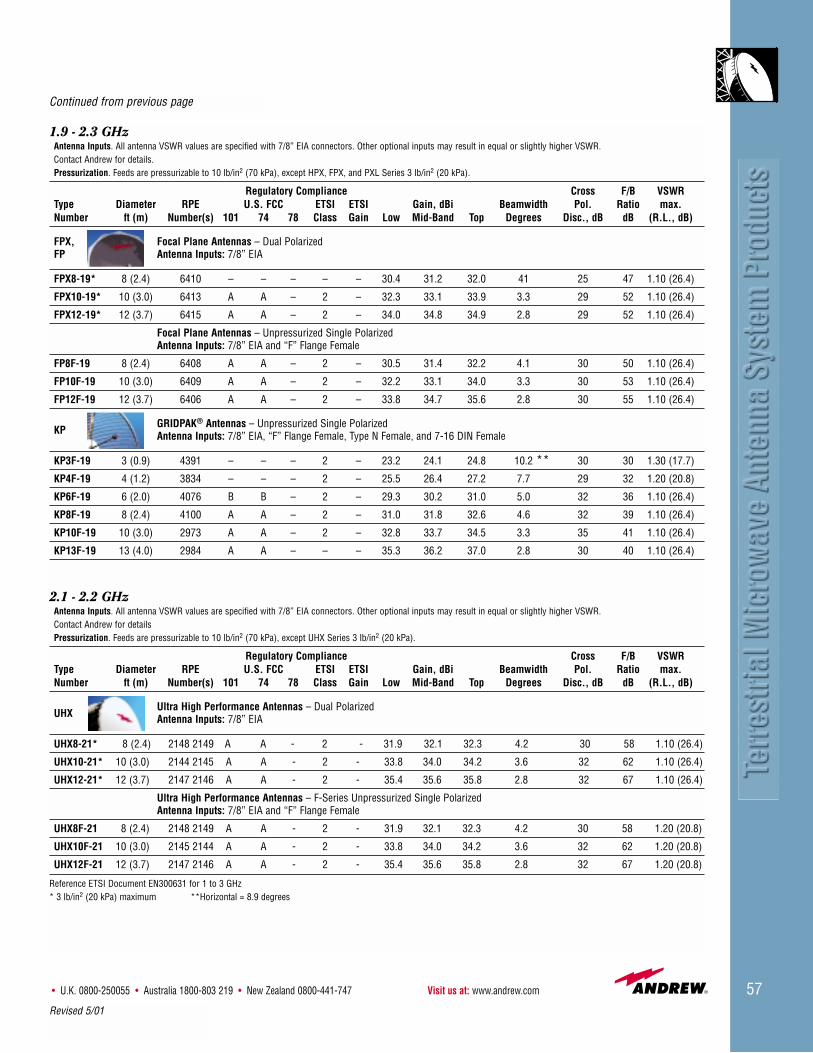
• U.K. 0800-250055 • Australia 1800-803 219 • New Zealand 0800-441-747 Visit us at: www.andrew.com 57
Continued from previous page
1.9 - 2.3 GHzAntenna Inputs. All antenna VSWR values are specified with 7/8” EIA connectors. Other optional inputs may result in equal or slightly higher VSWR. Contact Andrew for details.Pressurization. Feeds are pressurizable to 10 lb/in2 (70 kPa), except HPX, FPX, and PXL Series 3 lb/in2 (20 kPa).
Regulatory Compliance Cross F/B VSWRType Diameter RPE U.S. FCC ETSI ETSI Gain, dBi Beamwidth Pol. Ratio max.Number ft (m) Number(s) 101 74 78 Class Gain Low Mid-Band Top Degrees Disc., dB dB (R.L., dB)
FPX, Focal Plane Antennas – Dual PolarizedFP Antenna Inputs: 7/8” EIA
FPX8-19* 8 (2.4) 6410 – – – – – 30.4 31.2 32.0 41 25 47 1.10 (26.4)
FPX10-19* 10 (3.0) 6413 A A – 2 – 32.3 33.1 33.9 3.3 29 52 1.10 (26.4)
FPX12-19* 12 (3.7) 6415 A A – 2 – 34.0 34.8 34.9 2.8 29 52 1.10 (26.4)
Focal Plane Antennas – Unpressurized Single PolarizedAntenna Inputs: 7/8” EIA and “F” Flange Female
FP8F-19 8 (2.4) 6408 A A – 2 – 30.5 31.4 32.2 4.1 30 50 1.10 (26.4)
FP10F-19 10 (3.0) 6409 A A – 2 – 32.2 33.1 34.0 3.3 30 53 1.10 (26.4)
FP12F-19 12 (3.7) 6406 A A – 2 – 33.8 34.7 35.6 2.8 30 55 1.10 (26.4)
KPGRIDPAK® Antennas – Unpressurized Single PolarizedAntenna Inputs: 7/8” EIA, “F” Flange Female, Type N Female, and 7-16 DIN Female
KP3F-19 3 (0.9) 4391 – – – 2 – 23.2 24.1 24.8 10.2 30 30 1.30 (17.7)
KP4F-19 4 (1.2) 3834 – – – 2 – 25.5 26.4 27.2 7.7 29 32 1.20 (20.8)
KP6F-19 6 (2.0) 4076 B B – 2 – 29.3 30.2 31.0 5.0 32 36 1.10 (26.4)
KP8F-19 8 (2.4) 4100 A A – 2 – 31.0 31.8 32.6 4.6 32 39 1.10 (26.4)
KP10F-19 10 (3.0) 2973 A A – 2 – 32.8 33.7 34.5 3.3 35 41 1.10 (26.4)
KP13F-19 13 (4.0) 2984 A A – – – 35.3 36.2 37.0 2.8 30 40 1.10 (26.4)
2.1 - 2.2 GHzAntenna Inputs. All antenna VSWR values are specified with 7/8” EIA connectors. Other optional inputs may result in equal or slightly higher VSWR. Contact Andrew for detailsPressurization. Feeds are pressurizable to 10 lb/in2 (70 kPa), except UHX Series 3 lb/in2 (20 kPa).
Regulatory Compliance Cross F/B VSWRType Diameter RPE U.S. FCC ETSI ETSI Gain, dBi Beamwidth Pol. Ratio max.Number ft (m) Number(s) 101 74 78 Class Gain Low Mid-Band Top Degrees Disc., dB dB (R.L., dB)
UHXUltra High Performance Antennas – Dual PolarizedAntenna Inputs: 7/8” EIA
UHX8-21* 8 (2.4) 2148 2149 A A - 2 - 31.9 32.1 32.3 4.2 30 58 1.10 (26.4)
UHX10-21* 10 (3.0) 2144 2145 A A - 2 - 33.8 34.0 34.2 3.6 32 62 1.10 (26.4)
UHX12-21* 12 (3.7) 2147 2146 A A - 2 - 35.4 35.6 35.8 2.8 32 67 1.10 (26.4)
Ultra High Performance Antennas – F-Series Unpressurized Single PolarizedAntenna Inputs: 7/8” EIA and “F” Flange Female
UHX8F-21 8 (2.4) 2148 2149 A A - 2 - 31.9 32.1 32.3 4.2 30 58 1.20 (20.8)
UHX10F-21 10 (3.0) 2145 2144 A A - 2 - 33.8 34.0 34.2 3.6 32 62 1.20 (20.8)
UHX12F-21 12 (3.7) 2147 2146 A A - 2 - 35.4 35.6 35.8 2.8 32 67 1.20 (20.8)
Reference ETSI Document EN300631 for 1 to 3 GHz* 3 lb/in2 (20 kPa) maximum **Horizontal = 8.9 degrees
**
Revised 5/01
Customer Service Center - Call toll-free from: • U.S.A., Canada and Mexico 1-800-255-147958
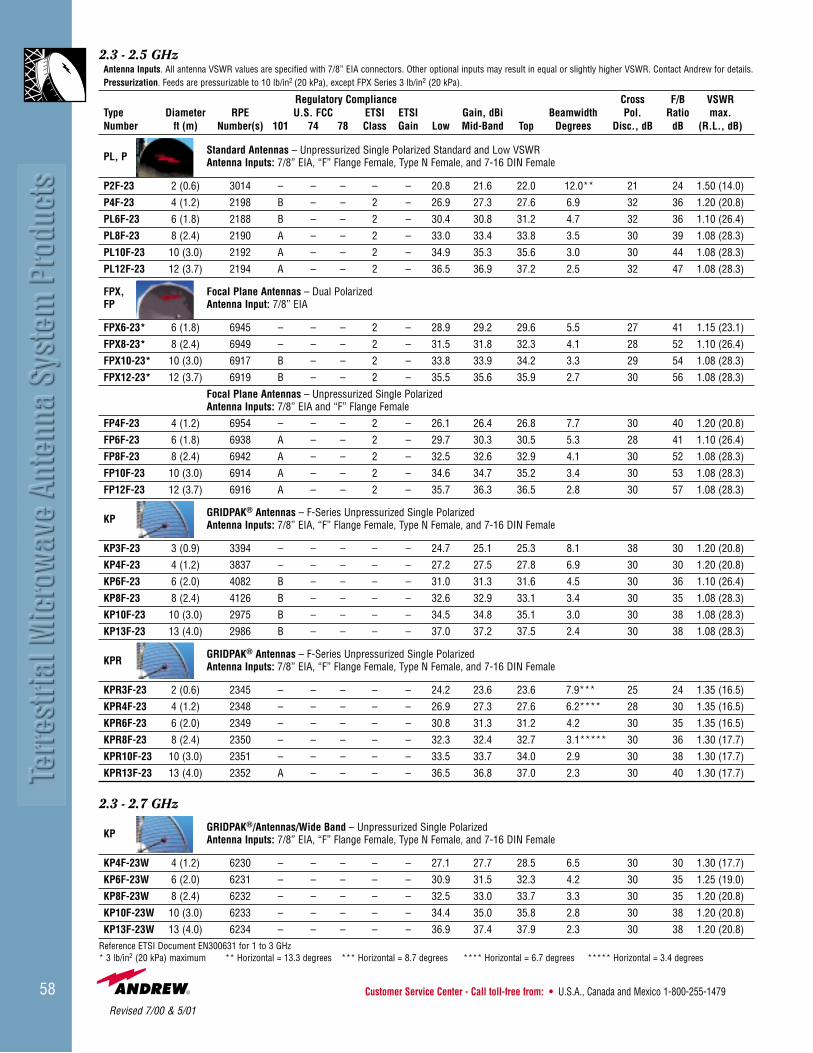
2.3 - 2.5 GHzAntenna Inputs. All antenna VSWR values are specified with 7/8” EIA connectors. Other optional inputs may result in equal or slightly higher VSWR. Contact Andrew for details.Pressurization. Feeds are pressurizable to 10 lb/in2 (20 kPa), except FPX Series 3 lb/in2 (20 kPa).
Regulatory Compliance Cross F/B VSWRType Diameter RPE U.S. FCC ETSI ETSI Gain, dBi Beamwidth Pol. Ratio max.Number ft (m) Number(s) 101 74 78 Class Gain Low Mid-Band Top Degrees Disc., dB dB (R.L., dB)
PL, PStandard Antennas – Unpressurized Single Polarized Standard and Low VSWRAntenna Inputs: 7/8” EIA, “F” Flange Female, Type N Female, and 7-16 DIN Female
P2F-23 2 (0.6) 3014 – – – – – 20.8 21.6 22.0 12.0** 21 24 1.50 (14.0)
P4F-23 4 (1.2) 2198 B – – 2 – 26.9 27.3 27.6 6.9 32 36 1.20 (20.8)
PL6F-23 6 (1.8) 2188 B – – 2 – 30.4 30.8 31.2 4.7 32 36 1.10 (26.4)
PL8F-23 8 (2.4) 2190 A – – 2 – 33.0 33.4 33.8 3.5 30 39 1.08 (28.3)
PL10F-23 10 (3.0) 2192 A – – 2 – 34.9 35.3 35.6 3.0 30 44 1.08 (28.3)
PL12F-23 12 (3.7) 2194 A – – 2 – 36.5 36.9 37.2 2.5 32 47 1.08 (28.3)
FPX, Focal Plane Antennas – Dual PolarizedFP Antenna Input: 7/8” EIA
FPX6-23* 6 (1.8) 6945 – – – 2 – 28.9 29.2 29.6 5.5 27 41 1.15 (23.1)
FPX8-23* 8 (2.4) 6949 – – – 2 – 31.5 31.8 32.3 4.1 28 52 1.10 (26.4)
FPX10-23* 10 (3.0) 6917 B – – 2 – 33.8 33.9 34.2 3.3 29 54 1.08 (28.3)
FPX12-23* 12 (3.7) 6919 B – – 2 – 35.5 35.6 35.9 2.7 30 56 1.08 (28.3)
Focal Plane Antennas – Unpressurized Single PolarizedAntenna Inputs: 7/8” EIA and “F” Flange Female
FP4F-23 4 (1.2) 6954 – – – 2 – 26.1 26.4 26.8 7.7 30 40 1.20 (20.8)
FP6F-23 6 (1.8) 6938 A – – 2 – 29.7 30.3 30.5 5.3 28 41 1.10 (26.4)
FP8F-23 8 (2.4) 6942 A – – 2 – 32.5 32.6 32.9 4.1 30 52 1.08 (28.3)
FP10F-23 10 (3.0) 6914 A – – 2 – 34.6 34.7 35.2 3.4 30 53 1.08 (28.3)
FP12F-23 12 (3.7) 6916 A – – 2 – 35.7 36.3 36.5 2.8 30 57 1.08 (28.3)
KPGRIDPAK® Antennas – F-Series Unpressurized Single PolarizedAntenna Inputs: 7/8” EIA, “F” Flange Female, Type N Female, and 7-16 DIN Female
KP3F-23 3 (0.9) 3394 – – – – – 24.7 25.1 25.3 8.1 38 30 1.20 (20.8)
KP4F-23 4 (1.2) 3837 – – – – – 27.2 27.5 27.8 6.9 30 30 1.20 (20.8)
KP6F-23 6 (2.0) 4082 B – – – – 31.0 31.3 31.6 4.5 30 36 1.10 (26.4)
KP8F-23 8 (2.4) 4126 B – – – – 32.6 32.9 33.1 3.4 30 35 1.08 (28.3)
KP10F-23 10 (3.0) 2975 B – – – – 34.5 34.8 35.1 3.0 30 38 1.08 (28.3)
KP13F-23 13 (4.0) 2986 B – – – – 37.0 37.2 37.5 2.4 30 38 1.08 (28.3)
KPRGRIDPAK® Antennas – F-Series Unpressurized Single PolarizedAntenna Inputs: 7/8” EIA, “F” Flange Female, Type N Female, and 7-16 DIN Female
KPR3F-23 2 (0.6) 2345 – – – – – 24.2 23.6 23.6 7.9*** 25 24 1.35 (16.5)
KPR4F-23 4 (1.2) 2348 – – – – – 26.9 27.3 27.6 6.2**** 28 30 1.35 (16.5)
KPR6F-23 6 (2.0) 2349 – – – – – 30.8 31.3 31.2 4.2 30 35 1.35 (16.5)
KPR8F-23 8 (2.4) 2350 – – – – – 32.3 32.4 32.7 3.1***** 30 36 1.30 (17.7)
KPR10F-23 10 (3.0) 2351 – – – – – 33.5 33.7 34.0 2.9 30 38 1.30 (17.7)
KPR13F-23 13 (4.0) 2352 A – – – – 36.5 36.8 37.0 2.3 30 40 1.30 (17.7)
2.3 - 2.7 GHz
KPGRIDPAK®/Antennas/Wide Band – Unpressurized Single PolarizedAntenna Inputs: 7/8” EIA, “F” Flange Female, Type N Female, and 7-16 DIN Female
KP4F-23W 4 (1.2) 6230 – – – – – 27.1 27.7 28.5 6.5 30 30 1.30 (17.7)
KP6F-23W 6 (2.0) 6231 – – – – – 30.9 31.5 32.3 4.2 30 35 1.25 (19.0)
KP8F-23W 8 (2.4) 6232 – – – – – 32.5 33.0 33.7 3.3 30 35 1.20 (20.8)
KP10F-23W 10 (3.0) 6233 – – – – – 34.4 35.0 35.8 2.8 30 38 1.20 (20.8)
KP13F-23W 13 (4.0) 6234 – – – – – 36.9 37.4 37.9 2.3 30 38 1.20 (20.8)Reference ETSI Document EN300631 for 1 to 3 GHz* 3 lb/in2 (20 kPa) maximum ** Horizontal = 13.3 degrees *** Horizontal = 8.7 degrees **** Horizontal = 6.7 degrees ***** Horizontal = 3.4 degrees
Revised 7/00 & 5/01

• U.K. 0800-250055 • Australia 1800-803 219 • New Zealand 0800-441-747 Visit us at: www.andrew.com 59
2.45 - 2.5 GHzAntenna Inputs. All antenna VSWR values are specified with 7/8” EIA connectors. Other optional inputs may result in equal or slightly higher VSWR. Contact Andrew for details.Pressurization. Feeds are pressurizable to 10 lb/in2 (70 kPa).
Regulatory Compliance Cross F/B VSWRType Diameter RPE U.S. FCC ETSI ETSI Gain, dBi Beamwidth Pol. Ratio max.Number ft (m) Number(s) 101 74 78 Class Gain Low Mid-Band Top Degrees Disc., dB dB (R.L., dB)
PStandard Antennas – Unpressurized Single PolarizedAntenna Inputs: 7/8” EIA, “F” Flange Female, Type N Female, and 7-16 DIN Female
P6F-24 6 (1.8) 2205 B – – 2 – 30.9 31.0 31.1 4.3 28 36 1.30 (17.7)
P8F-24 8 (2.4) 2207 A – – 2 – 33.4 33.5 33.6 3.2 28 39 1.30 (17.7)
2.48 - 2.7 GHzAntenna Inputs. All antenna VSWR values are specified with 7/8” EIA connectors. Other optional inputs may result in equal or slightly higher VSWR. Contact Andrew for details.Pressurization. Feeds are pressurizable to 10 lb/in2 (70 kPa) except FPX Series 3 lb/in2 (20 kPa).
Regulatory Compliance Cross F/B VSWRType Diameter RPE U.S. FCC ETSI ETSI Gain, dBi Beamwidth Pol. Ratio max.Number ft (m) Number(s) 101 74 78 Class Gain Low Mid-Band Top Degrees Disc., dB dB (R.L., dB)
HPHigh Performance Antennas – Unpressurized Single PolarizedAntenna Inputs: 7/8” EIA and “F” Flange Female
HP4F-25 4 (1.2) 1038 – – – 2 – 27 27.3 27.6 6.7 30 43 1.20 (20.8)
HP6F-25 6 (1.8) 1322E – – – 2 – 31.1 31.4 31.7 4.6 28 50 1.10 (26.4)
HP8F-25 8 (2.4) 1314 – – – 2 – 33.7 34 34.3 3.1 30 52 1.08 (28.3)
HP10F-25 10 (3.0) 3000 – – – 2 – 35.6 35.9 36.2 2.7 30 55 1.08 (28.3)
HP12F-25 12 (3.7) 1318 – – – 2 – 37.2 37.5 37.8 2.3 30 54 1.08 (28.3)
PL,PStandard Antennas – Unpressurized Single Polarized Standard and Low VSWRAntenna Inputs: 7/8” EIA, “F” Flange Female, Type N Female, and 7-16 DIN Female
P4F-25 4 (1.2) 1268 – – – – – 27.6 27.9 28.2 6.3 30 32 1.20 (20.8)
PL6F-25 6 (1.8) 1308 – – – – – 31.1 31.4 31.7 4.2 28 36 1.10 (26.4)
PL8F-25 8 (2.4) 1309 – – – 2 – 33.6 33.9 34.2 3.1 30 39 1.08 (28.3)
PL10F-25 10 (3.0) 1310 – – – 2 – 35.6 35.9 36.2 2.7 30 42 1.08 (28.3)
PL12F-25 12 (3.7) 1320 – – – 2 – 37.1 37.4 37.7 2.2 30 44 1.08 (28.3)
FPX, Focal Plane Antennas – Dual PolarizedFP Antenna Inputs: 7/8” EIA
FPX6-25* 6 (1.8) 6947 – – – – – 29.6 30.0 30.3 5.0 27 42 1.15 (23.1)
FPX8-25* 8 (2.4) 6951 – – – – – 32.3 32.6 32.7 5.0 27 52 1.15 (26.4)
FPX10-25* 10 (3.0) 6909 – – – 2 – 34.2 34.6 34.9 3.1 30 54 1.08 (28.3)
FPX12-25* 12 (3.7) 6911 – – – 2 – 35.9 36.3 36.8 2.6 30 56 1.08 (28.3)
Focal Plane Antennas – F-Series Unpressurized Single PolarizedAntenna Inputs: 7/8” EIA, “F” Flange Female, Type N Female, and 7-16 DIN Female
FP4F-25 4 (1.2) 6956 – – – 2 – 26.8 27.1 27.5 7.2 30 41 1.20 (20.8)
FP6F-25 6 (1.8) 6940 – – – 2 – 30.5 30.6 31.0 4.9 28 44 1.10 (26.4)
FP8F-25 8 (2.4) 6944 – – – 2 – 32.9 33.4 33.5 3.9 30 52 1.08 (26.4)
FP10F-25 10 (3.0) 6905 – – – 2 – 35.2 35.5 35.8 3.2 30 55 1.08 (28.3)
FP12F-25 12 (3.7) 6908 – – – 2 – 36.5 36.9 37.3 2.6 30 57 1.08 (28.3)
KPGRIDPAK® Antennas – Unpressurized Single PolarizedAntenna Inputs: 7/8” EIA, “F” Flange Female, Type N Female, and 7-16 DIN Female
KP3F-25 3 (0.9) 3395 – – – – – 25.3 25.2 25.4 7.7 32 30 1.20 (20.8)
KP4F-25 4 (1.2) 3841 – – – – – 27.8 28.2 28.6 6.1 30 31 1.20 (20.8)
KP6F-25 6 (2.0) 4084 – – – – – 31.6 32.0 32.4 4.0 30 35 1.10 (26.4)
KP8F-25 8 (2.4) 4128 – – – – – 33.1 33.6 33.8 3.2 30 37 1.08 (28.3)
KP10F-25 10 (3.0) 2977 – – – – – 35.1 35.5 35.9 2.7 31 38 1.08 (28.3)
KP13F-25 13 (4.0) 2988 – – – – – 37.5 37.8 38.0 2.3 30 38 1.08 (28.3)
Reference ETSI Document EN300631 for 1 to 3 GHz * 3 lb/in2 (20 kPa) maximum **Horizontal = 6.9 degrees
**
Revised 7/00 & 5/01\
Customer Service Center - Call toll-free from: • U.S.A., Canada and Mexico 1-800-255-147960
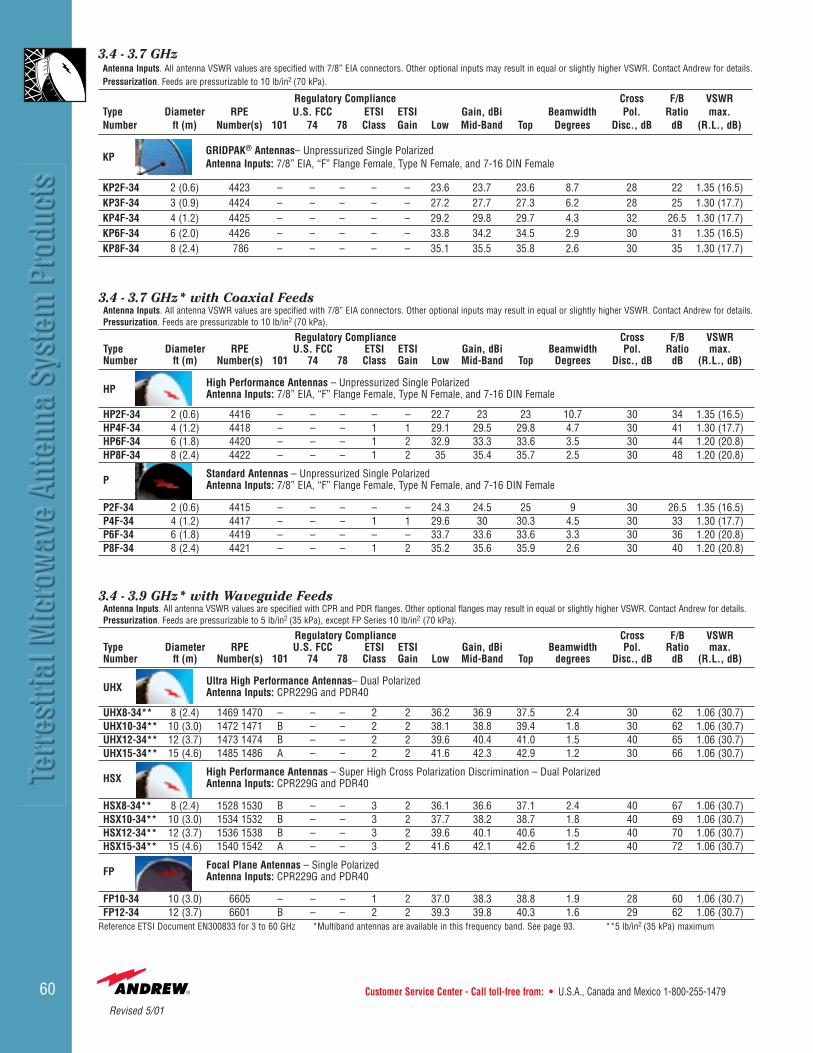
3.4 - 3.7 GHz* with Coaxial FeedsAntenna Inputs. All antenna VSWR values are specified with 7/8” EIA connectors. Other optional inputs may result in equal or slightly higher VSWR. Contact Andrew for details.Pressurization. Feeds are pressurizable to 10 lb/in2 (70 kPa).
Regulatory Compliance Cross F/B VSWRType Diameter RPE U.S. FCC ETSI ETSI Gain, dBi Beamwidth Pol. Ratio max.Number ft (m) Number(s) 101 74 78 Class Gain Low Mid-Band Top Degrees Disc., dB dB (R.L., dB)
HPHigh Performance Antennas – Unpressurized Single PolarizedAntenna Inputs: 7/8” EIA, “F” Flange Female, Type N Female, and 7-16 DIN Female
HP2F-34 2 (0.6) 4416 – – – – – 22.7 23 23 10.7 30 34 1.35 (16.5)HP4F-34 4 (1.2) 4418 – – – 1 1 29.1 29.5 29.8 4.7 30 41 1.30 (17.7)HP6F-34 6 (1.8) 4420 – – – 1 2 32.9 33.3 33.6 3.5 30 44 1.20 (20.8)HP8F-34 8 (2.4) 4422 – – – 1 2 35 35.4 35.7 2.5 30 48 1.20 (20.8)
PStandard Antennas – Unpressurized Single PolarizedAntenna Inputs: 7/8” EIA, “F” Flange Female, Type N Female, and 7-16 DIN Female
P2F-34 2 (0.6) 4415 – – – – – 24.3 24.5 25 9 30 26.5 1.35 (16.5)P4F-34 4 (1.2) 4417 – – – 1 1 29.6 30 30.3 4.5 30 33 1.30 (17.7)P6F-34 6 (1.8) 4419 – – – – – 33.7 33.6 33.6 3.3 30 36 1.20 (20.8)P8F-34 8 (2.4) 4421 – – – 1 2 35.2 35.6 35.9 2.6 30 40 1.20 (20.8)
3.4 - 3.9 GHz* with Waveguide FeedsAntenna Inputs. All antenna VSWR values are specified with CPR and PDR flanges. Other optional flanges may result in equal or slightly higher VSWR. Contact Andrew for details.Pressurization. Feeds are pressurizable to 5 lb/in2 (35 kPa), except FP Series 10 lb/in2 (70 kPa).
Regulatory Compliance Cross F/B VSWRType Diameter RPE U.S. FCC ETSI ETSI Gain, dBi Beamwidth Pol. Ratio max.Number ft (m) Number(s) 101 74 78 Class Gain Low Mid-Band Top degrees Disc., dB dB (R.L., dB)
UHXUltra High Performance Antennas– Dual PolarizedAntenna Inputs: CPR229G and PDR40
UHX8-34** 8 (2.4) 1469 1470 – – – 2 2 36.2 36.9 37.5 2.4 30 62 1.06 (30.7)UHX10-34** 10 (3.0) 1472 1471 B – – 2 2 38.1 38.8 39.4 1.8 30 62 1.06 (30.7)UHX12-34** 12 (3.7) 1473 1474 B – – 2 2 39.6 40.4 41.0 1.5 40 65 1.06 (30.7)UHX15-34** 15 (4.6) 1485 1486 A – – 2 2 41.6 42.3 42.9 1.2 30 66 1.06 (30.7)
HSXHigh Performance Antennas – Super High Cross Polarization Discrimination – Dual PolarizedAntenna Inputs: CPR229G and PDR40
HSX8-34** 8 (2.4) 1528 1530 B – – 3 2 36.1 36.6 37.1 2.4 40 67 1.06 (30.7)HSX10-34** 10 (3.0) 1534 1532 B – – 3 2 37.7 38.2 38.7 1.8 40 69 1.06 (30.7)HSX12-34** 12 (3.7) 1536 1538 B – – 3 2 39.6 40.1 40.6 1.5 40 70 1.06 (30.7)HSX15-34** 15 (4.6) 1540 1542 A – – 3 2 41.6 42.1 42.6 1.2 40 72 1.06 (30.7)
FPFocal Plane Antennas – Single PolarizedAntenna Inputs: CPR229G and PDR40
FP10-34 10 (3.0) 6605 – – – 1 2 37.0 38.3 38.8 1.9 28 60 1.06 (30.7)FP12-34 12 (3.7) 6601 B – – 2 2 39.3 39.8 40.3 1.6 29 62 1.06 (30.7)
Reference ETSI Document EN300833 for 3 to 60 GHz *Multiband antennas are available in this frequency band. See page 93. **5 lb/in2 (35 kPa) maximum
3.4 - 3.7 GHzAntenna Inputs. All antenna VSWR values are specified with 7/8” EIA connectors. Other optional inputs may result in equal or slightly higher VSWR. Contact Andrew for details.Pressurization. Feeds are pressurizable to 10 lb/in2 (70 kPa).
Regulatory Compliance Cross F/B VSWRType Diameter RPE U.S. FCC ETSI ETSI Gain, dBi Beamwidth Pol. Ratio max.Number ft (m) Number(s) 101 74 78 Class Gain Low Mid-Band Top Degrees Disc., dB dB (R.L., dB)
KPGRIDPAK® Antennas– Unpressurized Single PolarizedAntenna Inputs: 7/8” EIA, “F” Flange Female, Type N Female, and 7-16 DIN Female
KP2F-34 2 (0.6) 4423 – – – – – 23.6 23.7 23.6 8.7 28 22 1.35 (16.5)KP3F-34 3 (0.9) 4424 – – – – – 27.2 27.7 27.3 6.2 28 25 1.30 (17.7)KP4F-34 4 (1.2) 4425 – – – – – 29.2 29.8 29.7 4.3 32 26.5 1.30 (17.7)KP6F-34 6 (2.0) 4426 – – – – – 33.8 34.2 34.5 2.9 30 31 1.35 (16.5)KP8F-34 8 (2.4) 786 – – – – – 35.1 35.5 35.8 2.6 30 35 1.30 (17.7)
Revised 5/01
• U.K. 0800-250055 • Australia 1800-803 219 • New Zealand 0800-441-747 Visit us at: www.andrew.com 61
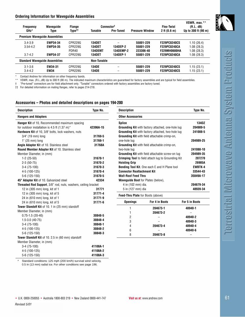
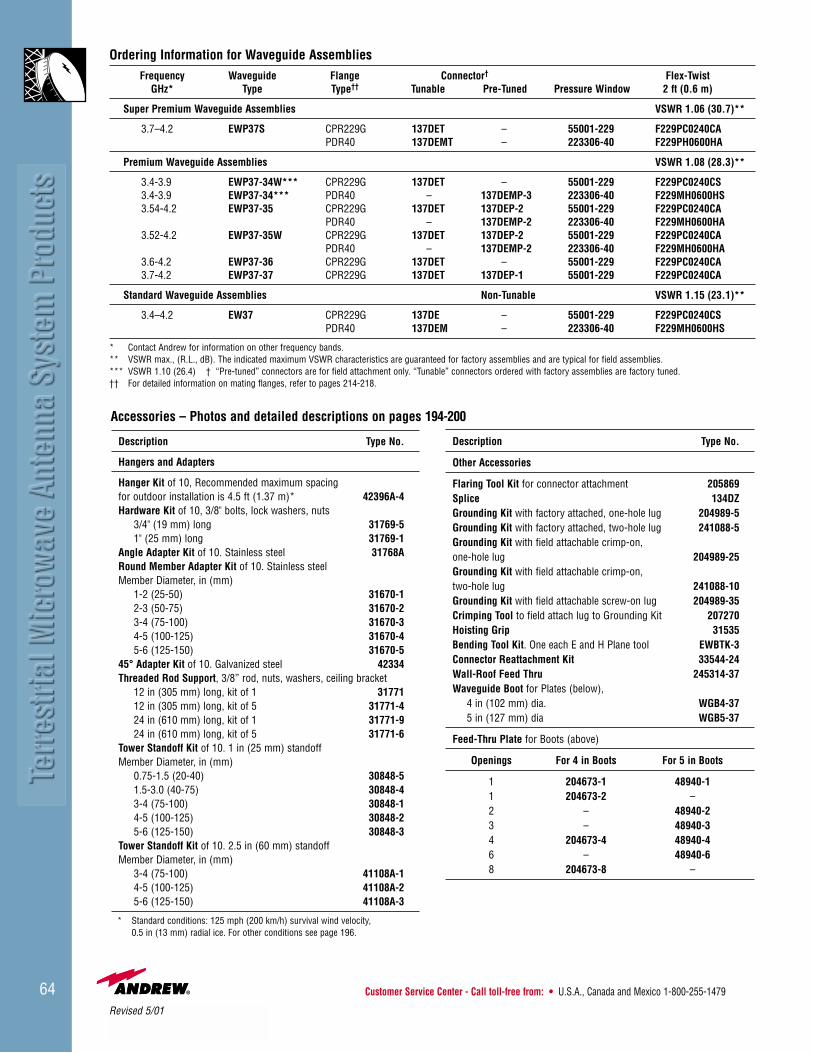
Ordering Information for Waveguide AssembliesVSWR, max.**
Frequency Waveguide Flange Connector† Flex-Twist (R.L. dB)GHz* Type Type†† Tunable Pre-Tuned Pressure Window 2 ft (0.6 m) Up to 300 ft (90 m)
Premium Waveguide Assemblies
3.4-3.9 EWP34-34 CPR229G 134DET – 55001-229 F229PC0240CS 1.10 (26.4)3.54-4.2 EWP34-35 CPR229G 134DET 134DEP-2 55001-229 F229PC0240CA 1.08 (28.3)
PDR40 134DEMT 134DEMP-2 223306-40 F229MH0600HA 1.08 (28.3)3.7-4.2 EWP34-37 CPR229G 134DET 134DEP-1 55001-229 F229PC0240CA 1.08 (28.3)
Standard Waveguide Assemblies Non-Tunable
3.1-3.6 EW34-31 CPR229G 134DE – 55001-229 F229PC0240CS 1.15 (23.1)3.4-4.2 EW34 CPR229G 134DE – 55001-229 F229PC0240CS 1.15 (23.1)
* Contact Andrew for information on other frequency bands.** VSWR, max. (R.L.,dB) Up to 300 ft (90 m). The indicated maximum characteristics are guaranteed for factory assemblies and are typical for field assemblies.† “Pre-tuned” connectors are for field attachment only. “Tunable” connectors ordered with factory assemblies are factory tuned.†† For detailed information on mating flanges, refer to pages 214-218.
Description Type No.
Hangers and Adapters
Hanger Kit of 10, Recommended maximum spacingfor outdoor installation is 4.5 ft (1.37 m)* 42396A-15Hardware Kit of 10, 3/8" bolts, lock washers, nuts
3/4" (19 mm) long 31769-51" (25 mm) long 31769-1
Angle Adapter Kit of 10. Stainless steel 31768ARound Member Adapter Kit of 10. Stainless steelMember Diameter, in (mm)
1-2 (25-50) 31670-12-3 (50-75) 31670-23-4 (75-100) 31670-34-5 (100-125) 31670-45-6 (125-150) 31670-5
45° Adapter Kit of 10. Galvanized steel 42334Threaded Rod Support, 3/8” rod, nuts, washers, ceiling bracket
12 in (305 mm) long, kit of 1 3177112 in (305 mm) long, kit of 5 31771-424 in (610 mm) long, kit of 1 31771-924 in (610 mm) long, kit of 5 31771-6
Tower Standoff Kit of 10. 1 in (25 mm) standoffMember Diameter, in (mm)
0.75-1.5 (20-40) 30848-51.5-3.0 (40-75) 30848-43-4 (75-100) 30848-14-5 (100-125) 30848-25-6 (125-150) 30848-3
Tower Standoff Kit of 10. 2.5 in (60 mm) standoffMember Diameter, in (mm)
3-4 (75-100) 41108A-14-5 (100-125) 41108A-25-6 (125-150) 41108A-3
* Standard conditions: 125 mph (200 km/h) survival wind velocity, 0.5 in (13 mm) radial ice. For other conditions see page 196.
Accessories – Photos and detailed descriptions on pages 194-200
Description Type No.
Other Accessories
Splice 134DZGrounding Kit with factory attached, one-hole lug 204989-5Grounding Kit with factory attached, two-hole lug 241088-5Grounding Kit with field attachable crimp-on, one-hole lug 204989-25Grounding Kit with field attachable crimp-on, two-hole lug 241088-10Grounding Kit with field attachable screw-on lug 204989-35Crimping Tool to field attach lug to Grounding Kit 207270Hoisting Grip 26985ABending Tool Kit. One each E and H Plane tool EWBTK-4Connector Reattachment Kit 33544-43Wall-Roof Feed Thru 35849A-17Waveguide Boot for Plates (below),
4 in (102 mm) dia. 204679-345 in (127 mm) dia 48939-34
Feed-Thru Plate for Boots (above)
Openings For 4 in Boots For 5 in Boots
1 204673-1 48940-11 204673-2 –2 – 48940-23 – 48940-34 204673-4 48940-46 – 48940-68 204673-8 –
Revised 5/01
Customer Service Center - Call toll-free from: • U.S.A., Canada and Mexico 1-800-255-147962
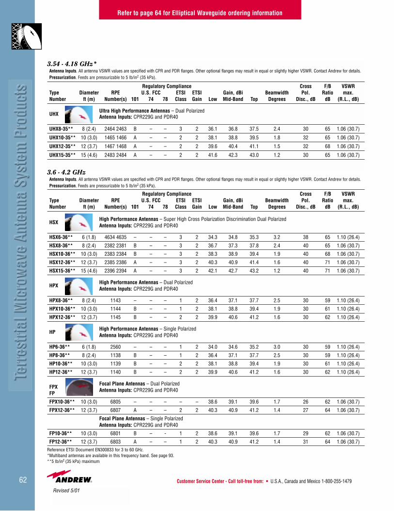
3.54 - 4.18 GHz*Antenna Inputs. All antenna VSWR values are specified with CPR and PDR flanges. Other optional flanges may result in equal or slightly higher VSWR. Contact Andrew for details.Pressurization. Feeds are pressurizable to 5 lb/in2 (35 kPa).
Regulatory Compliance Cross F/B VSWRType Diameter RPE U.S. FCC ETSI ETSI Gain, dBi Beamwidth Pol. Ratio max.Number ft (m) Number(s) 101 74 78 Class Gain Low Mid-Band Top Degrees Disc., dB dB (R.L., dB)
UHXUltra High Performance Antennas – Dual PolarizedAntenna Inputs: CPR229G and PDR40
UHX8-35** 8 (2.4) 2464 2463 B – – 3 2 36.1 36.8 37.5 2.4 30 65 1.06 (30.7)
UHX10-35** 10 (3.0) 1465 1466 A – – 2 2 38.1 38.8 39.5 1.8 32 65 1.06 (30.7)
UHX12-35** 12 (3.7) 1467 1468 A – – 2 2 39.6 40.4 41.1 1.5 32 68 1.06 (30.7)
UHX15-35** 15 (4.6) 2483 2484 A – – 2 2 41.6 42.3 43.0 1.2 30 65 1.06 (30.7)
3.6 - 4.2 GHzAntenna Inputs. All antenna VSWR values are specified with CPR and PDR flanges. Other optional flanges may result in equal or slightly higher VSWR. Contact Andrew for details.Pressurization. Feeds are pressurizable to 5 lb/in2 (35 kPa).
Regulatory Compliance Cross F/B VSWRType Diameter RPE U.S. FCC ETSI ETSI Gain, dBi Beamwidth Pol. Ratio max.Number ft (m) Number(s) 101 74 78 Class Gain Low Mid-Band Top Degrees Disc., dB dB (R.L., dB)
HSXHigh Performance Antennas – Super High Cross Polarization Discrimination Dual PolarizedAntenna Inputs: CPR229G and PDR40
HSX6-36** 6 (1.8) 4634 4635 – – – 3 2 34.3 34.8 35.3 3.2 38 65 1.10 (26.4)
HSX8-36** 8 (2.4) 2382 2381 B – – 3 2 36.7 37.3 37.8 2.4 40 65 1.06 (30.7)
HSX10-36** 10 (3.0) 2383 2384 B – – 3 2 38.3 38.9 39.4 1.9 40 68 1.06 (30.7)
HSX12-36** 12 (3.7) 2385 2386 A – – 3 2 40.3 40.9 41.4 1.6 40 71 1.06 (30.7)
HSX15-36** 15 (4.6) 2396 2394 A – – 3 2 42.1 42.7 43.2 1.2 40 71 1.06 (30.7)
HPXHigh Performance Antennas – Dual PolarizedAntenna Inputs: CPR229G and PDR40
HPX8-36** 8 (2.4) 1143 – – – 1 2 36.4 37.1 37.7 2.5 30 59 1.10 (26.4)
HPX10-36** 10 (3.0) 1144 B – – 1 2 38.1 38.8 39.4 1.9 30 61 1.10 (26.4)
HPX12-36** 12 (3.7) 1145 B – – 2 2 39.9 40.6 41.2 1.6 30 62 1.10 (26.4)
HPHigh Performance Antennas – Single PolarizedAntenna Inputs: CPR229G and PDR40
HP6-36** 6 (1.8) 2560 – – – 1 2 34.0 34.6 35.2 3.0 30 59 1.10 (26.4)
HP8-36** 8 (2.4) 1138 B – – 1 2 36.4 37.1 37.7 2.5 30 59 1.10 (26.4)
HP10-36** 10 (3.0) 1139 B – – 2 2 38.1 38.8 39.4 1.9 30 61 1.10 (26.4)
HP12-36** 12 (3.7) 1140 B – – 2 2 39.9 40.6 41.2 1.6 30 62 1.10 (26.4)
FPXFocal Plane Antennas – Dual Polarized
FPAntenna Inputs: CPR229G and PDR40
FPX10-36** 10 (3.0) 6805 – – – – – 38.6 39.1 39.6 1.7 26 62 1.06 (30.7)
FPX12-36** 12 (3.7) 6807 A – – 2 2 40.3 40.9 41.2 1.4 27 64 1.06 (30.7)
Focal Plane Antennas – Single PolarizedAntenna Inputs: CPR229G and PDR40
FP10-36** 10 (3.0) 6801 B – - 1 2 38.6 39.1 39.6 1.7 29 62 1.06 (30.7)
FP12-36** 12 (3.7) 6803 A – – 1 2 40.3 40.9 41.2 1.4 31 64 1.06 (30.7)Reference ETSI Document EN300833 for 3 to 60 GHz.*Multiband antennas are available in this frequency band. See page 93.**5 lb/in2 (35 kPa) maximum
Refer to page 64 for Elliptical Waveguide ordering information
Revised 5/01
• U.K. 0800-250055 • Australia 1800-803 219 • New Zealand 0800-441-747 Visit us at: www.andrew.com 63
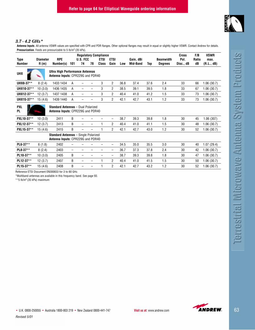
3.7 - 4.2 GHz*Antenna Inputs. All antenna VSWR values are specified with CPR and PDR flanges. Other optional flanges may result in equal or slightly higher VSWR. Contact Andrew for details.Pressurization. Feeds are pressurizable to 5 lb/in2 (35 kPa).
Regulatory Compliance Cross F/B VSWRType Diameter RPE U.S. FCC ETSI ETSI Gain, dBi Beamwidth Pol. Ratio max.Number ft (m) Number(s) 101 74 78 Class Gain Low Mid-Band Top Degrees Disc., dB dB (R.L., dB)
UHXUltra High Performance AntennasAntenna Inputs: CPR229G and PDR40
UHX8-37** 8 (2.4) 1433 1434 A – – 3 2 36.8 37.4 37.6 2.4 33 66 1.06 (30.7)
UHX10-37** 10 (3.0) 1436 1435 A – – 3 2 38.5 39.1 39.5 1.8 33 67 1.06 (30.7)
UHX12-37** 12 (3.7) 1437 1438 A – – 3 2 40.4 41.0 41.2 1.5 33 73 1.06 (30.7)
UHX15-37** 15 (4.6) 1439 1440 A – – 3 2 42.1 42.7 43.1 1.2 33 73 1.06 (30.7)
PXL Standard Antennas – Dual PolarizedPL Antenna Inputs: CPR229G and PDR40
PXL10-37** 10 (3.0) 2411 B – – – – 38.7 39.3 39.8 1.8 30 45 1.06 (307)
PXL12-37** 12 (3.7) 2413 B – – 1 2 40.4 41.0 41.1 1.5 30 48 1.06 (30.7)
PXL15-37** 15 (4.6) 2415 B – – 1 2 42.1 42.7 43.0 1.2 30 52 1.06 (30.7)
Standard Antennas – Single PolarizedAntenna Inputs: CPR229G and PDR40
PL6-37** 6 (1.8) 2402 – – – – – 34.5 35.0 35.5 3.0 30 40 1.07 (29.4)
PL8-37** 8 (2.4) 2403 – – – – – 36.7 37.3 37.8 2.4 30 42 1.06 (30.7)
PL10-37** 10 (3.0) 2405 B – – – – 38.7 39.3 39.8 1.8 30 47 1.06 (30.7)
PL12-37** 12 (3.7) 2407 B – – 1 2 40.4 41.0 41.5 1.5 30 50 1.06 (30.7)
PL15-37** 15 (4.6) 2408 B – – 1 2 42.1 42.7 43.2 1.2 30 52 1.06 (30.7)
Reference ETSI Document EN300833 for 3 to 60 GHz.*Multiband antennas are available in this frequency band. See page 93.**5 lb/in2 (35 kPa) maximum
Refer to page 64 for Elliptical Waveguide ordering information
Revised 5/01
Customer Service Center - Call toll-free from: • U.S.A., Canada and Mexico 1-800-255-147964
Ordering Information for Waveguide AssembliesFrequency Waveguide Flange Connector† Flex-Twist
GHz* Type Type†† Tunable Pre-Tuned Pressure Window 2 ft (0.6 m)
Super Premium Waveguide Assemblies VSWR 1.06 (30.7)**
3.7–4.2 EWP37S CPR229G 137DET – 55001-229 F229PC0240CAPDR40 137DEMT – 223306-40 F229PH0600HA
Premium Waveguide Assemblies VSWR 1.08 (28.3)**
3.4-3.9 EWP37-34W*** CPR229G 137DET – 55001-229 F229PC0240CS3.4-3.9 EWP37-34*** PDR40 – 137DEMP-3 223306-40 F229MH0600HS3.54-4.2 EWP37-35 CPR229G 137DET 137DEP-2 55001-229 F229PC0240CA
PDR40 – 137DEMP-2 223306-40 F229MH0600HA3.52-4.2 EWP37-35W CPR229G 137DET 137DEP-2 55001-229 F229PC0240CA
PDR40 – 137DEMP-2 223306-40 F229MH0600HA3.6-4.2 EWP37-36 CPR229G 137DET – 55001-229 F229PC0240CA3.7-4.2 EWP37-37 CPR229G 137DET 137DEP-1 55001-229 F229PC0240CA
Standard Waveguide Assemblies Non-Tunable VSWR 1.15 (23.1)**
3.4–4.2 EW37 CPR229G 137DE – 55001-229 F229PC0240CSPDR40 137DEM – 223306-40 F229MH0600HS
* Contact Andrew for information on other frequency bands.** VSWR max., (R.L., dB). The indicated maximum VSWR characteristics are guaranteed for factory assemblies and are typical for field assemblies.*** VSWR 1.10 (26.4) † “Pre-tuned” connectors are for field attachment only. “Tunable” connectors ordered with factory assemblies are factory tuned. †† For detailed information on mating flanges, refer to pages 214-218.
Description Type No.
Hangers and Adapters
Hanger Kit of 10, Recommended maximum spacingfor outdoor installation is 4.5 ft (1.37 m)* 42396A-4Hardware Kit of 10, 3/8" bolts, lock washers, nuts
3/4" (19 mm) long 31769-51" (25 mm) long 31769-1
Angle Adapter Kit of 10. Stainless steel 31768ARound Member Adapter Kit of 10. Stainless steelMember Diameter, in (mm)
1-2 (25-50) 31670-12-3 (50-75) 31670-23-4 (75-100) 31670-34-5 (100-125) 31670-45-6 (125-150) 31670-5
45° Adapter Kit of 10. Galvanized steel 42334Threaded Rod Support, 3/8” rod, nuts, washers, ceiling bracket
12 in (305 mm) long, kit of 1 3177112 in (305 mm) long, kit of 5 31771-424 in (610 mm) long, kit of 1 31771-924 in (610 mm) long, kit of 5 31771-6
Tower Standoff Kit of 10. 1 in (25 mm) standoffMember Diameter, in (mm)
0.75-1.5 (20-40) 30848-51.5-3.0 (40-75) 30848-43-4 (75-100) 30848-14-5 (100-125) 30848-25-6 (125-150) 30848-3
Tower Standoff Kit of 10. 2.5 in (60 mm) standoffMember Diameter, in (mm)
3-4 (75-100) 41108A-14-5 (100-125) 41108A-25-6 (125-150) 41108A-3
* Standard conditions: 125 mph (200 km/h) survival wind velocity, 0.5 in (13 mm) radial ice. For other conditions see page 196.
Description Type No.
Other Accessories
Flaring Tool Kit for connector attachment 205869Splice 134DZGrounding Kit with factory attached, one-hole lug 204989-5Grounding Kit with factory attached, two-hole lug 241088-5Grounding Kit with field attachable crimp-on, one-hole lug 204989-25Grounding Kit with field attachable crimp-on, two-hole lug 241088-10Grounding Kit with field attachable screw-on lug 204989-35Crimping Tool to field attach lug to Grounding Kit 207270Hoisting Grip 31535Bending Tool Kit. One each E and H Plane tool EWBTK-3Connector Reattachment Kit 33544-24Wall-Roof Feed Thru 245314-37Waveguide Boot for Plates (below),
4 in (102 mm) dia. WGB4-375 in (127 mm) dia WGB5-37
Feed-Thru Plate for Boots (above)
Openings For 4 in Boots For 5 in Boots
1 204673-1 48940-11 204673-2 –2 – 48940-23 – 48940-34 204673-4 48940-46 – 48940-68 204673-8 –
Accessories – Photos and detailed descriptions on pages 194-200
Revised 5/01
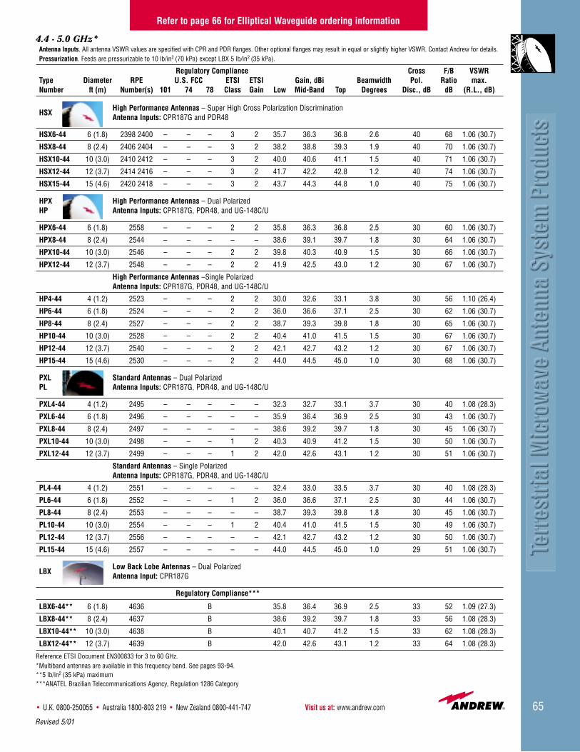
• U.K. 0800-250055 • Australia 1800-803 219 • New Zealand 0800-441-747 Visit us at: www.andrew.com 65
4.4 - 5.0 GHz*Antenna Inputs. All antenna VSWR values are specified with CPR and PDR flanges. Other optional flanges may result in equal or slightly higher VSWR. Contact Andrew for details.Pressurization. Feeds are pressurizable to 10 lb/in2 (70 kPa) except LBX 5 lb/in2 (35 kPa).
Regulatory Compliance Cross F/B VSWRType Diameter RPE U.S. FCC ETSI ETSI Gain, dBi Beamwidth Pol. Ratio max.Number ft (m) Number(s) 101 74 78 Class Gain Low Mid-Band Top Degrees Disc., dB dB (R.L., dB)
HSXHigh Performance Antennas – Super High Cross Polarization DiscriminationAntenna Inputs: CPR187G and PDR48
HSX6-44 6 (1.8) 2398 2400 – – – 3 2 35.7 36.3 36.8 2.6 40 68 1.06 (30.7)
HSX8-44 8 (2.4) 2406 2404 – – – 3 2 38.2 38.8 39.3 1.9 40 70 1.06 (30.7)
HSX10-44 10 (3.0) 2410 2412 – – – 3 2 40.0 40.6 41.1 1.5 40 71 1.06 (30.7)
HSX12-44 12 (3.7) 2414 2416 – – – 3 2 41.7 42.2 42.8 1.2 40 74 1.06 (30.7)
HSX15-44 15 (4.6) 2420 2418 – – – 3 2 43.7 44.3 44.8 1.0 40 75 1.06 (30.7)
HPX High Performance Antennas – Dual PolarizedHP Antenna Inputs: CPR187G, PDR48, and UG-148C/U
HPX6-44 6 (1.8) 2558 – – – 2 2 35.8 36.3 36.8 2.5 30 60 1.06 (30.7)
HPX8-44 8 (2.4) 2544 – – – – – 38.6 39.1 39.7 1.8 30 64 1.06 (30.7)
HPX10-44 10 (3.0) 2546 – – – 2 2 39.8 40.3 40.9 1.5 30 66 1.06 (30.7)
HPX12-44 12 (3.7) 2548 – – – 2 2 41.9 42.5 43.0 1.2 30 67 1.06 (30.7)
High Performance Antennas –Single PolarizedAntenna Inputs: CPR187G, PDR48, and UG-148C/U
HP4-44 4 (1.2) 2523 – – – 2 2 30.0 32.6 33.1 3.8 30 56 1.10 (26.4)
HP6-44 6 (1.8) 2524 – – – 2 2 36.0 36.6 37.1 2.5 30 62 1.06 (30.7)
HP8-44 8 (2.4) 2527 – – – 2 2 38.7 39.3 39.8 1.8 30 65 1.06 (30.7)
HP10-44 10 (3.0) 2528 – – – 2 2 40.4 41.0 41.5 1.5 30 67 1.06 (30.7)
HP12-44 12 (3.7) 2540 – – – 2 2 42.1 42.7 43.2 1.2 30 67 1.06 (30.7)
HP15-44 15 (4.6) 2530 – – – 2 2 44.0 44.5 45.0 1.0 30 68 1.06 (30.7)
PXL Standard Antennas – Dual PolarizedPL Antenna Inputs: CPR187G, PDR48, and UG-148C/U
PXL4-44 4 (1.2) 2495 – – – – – 32.3 32.7 33.1 3.7 30 40 1.08 (28.3)
PXL6-44 6 (1.8) 2496 – – – – – 35.9 36.4 36.9 2.5 30 43 1.06 (30.7)
PXL8-44 8 (2.4) 2497 – – – – – 38.6 39.2 39.7 1.8 30 45 1.06 (30.7)
PXL10-44 10 (3.0) 2498 – – – 1 2 40.3 40.9 41.2 1.5 30 50 1.06 (30.7)
PXL12-44 12 (3.7) 2499 – – – 1 2 42.0 42.6 43.1 1.2 30 51 1.06 (30.7)
Standard Antennas – Single PolarizedAntenna Inputs: CPR187G, PDR48, and UG-148C/U
PL4-44 4 (1.2) 2551 – – – – – 32.4 33.0 33.5 3.7 30 40 1.08 (28.3)
PL6-44 6 (1.8) 2552 – – – 1 2 36.0 36.6 37.1 2.5 30 44 1.06 (30.7)
PL8-44 8 (2.4) 2553 – – – – – 38.7 39.3 39.8 1.8 30 45 1.06 (30.7)
PL10-44 10 (3.0) 2554 – – – 1 2 40.4 41.0 41.5 1.5 30 49 1.06 (30.7)
PL12-44 12 (3.7) 2556 – – – – – 42.1 42.7 43.2 1.2 30 50 1.06 (30.7)
PL15-44 15 (4.6) 2557 – – – – – 44.0 44.5 45.0 1.0 29 51 1.06 (30.7)
LBXLow Back Lobe Antennas – Dual PolarizedAntenna Input: CPR187G
Regulatory Compliance***
LBX6-44** 6 (1.8) 4636 B 35.8 36.4 36.9 2.5 33 52 1.09 (27.3)
LBX8-44** 8 (2.4) 4637 B 38.6 39.2 39.7 1.8 33 56 1.08 (28.3)
LBX10-44** 10 (3.0) 4638 B 40.1 40.7 41.2 1.5 33 62 1.08 (28.3)
LBX12-44** 12 (3.7) 4639 B 42.0 42.6 43.1 1.2 33 64 1.08 (28.3)
Reference ETSI Document EN300833 for 3 to 60 GHz.*Multiband antennas are available in this frequency band. See pages 93-94.**5 lb/in2 (35 kPa) maximum***ANATEL Brazilian Telecommunications Agency, Regulation 1286 Category
Refer to page 66 for Elliptical Waveguide ordering information
Revised 5/01
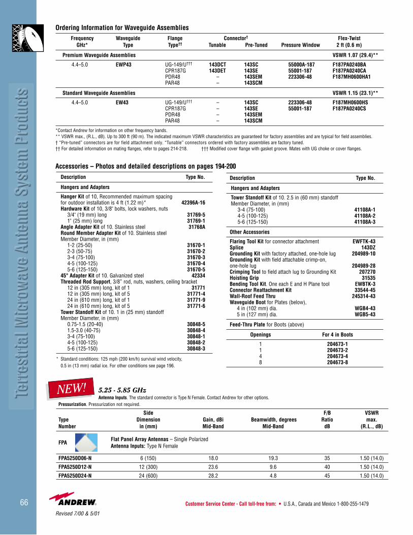
Customer Service Center - Call toll-free from: • U.S.A., Canada and Mexico 1-800-255-147966
Ordering Information for Waveguide AssembliesFrequency Waveguide Flange Connector† Flex-Twist
GHz* Type Type†† Tunable Pre-Tuned Pressure Window 2 ft (0.6 m)
Premium Waveguide Assemblies VSWR 1.07 (29.4)**
4.4–5.0 EWP43 UG-149/U††† 143DCT 143SC 55000A-187 F187PA0240BACPR187G 143DET 143SE 55001-187 F187PA0240CAPDR48 – 143SEM 223306-48 F187MH0600HA1PAR48 – 143SCM
Standard Waveguide Assemblies VSWR 1.15 (23.1)**
4.4–5.0 EW43 UG-149/U††† – 143SC 223306-48 F187MH0600HSCPR187G – 143SE 55001-187 F187PA0240CSPDR48 – 143SEMPAR48 – 143SCM
*Contact Andrew for information on other frequency bands.** VSWR max., (R.L., dB). Up to 300 ft (90 m). The indicated maximum VSWR characteristics are guaranteed for factory assemblies and are typical for field assemblies.† “Pre-tuned” connectors are for field attachment only. “Tunable” connectors ordered with factory assemblies are factory tuned. †† For detailed information on mating flanges, refer to pages 214-218. ††† Modified cover flange with gasket groove. Mates with UG choke or cover flanges.
Description Type No.
Hangers and Adapters
Hanger Kit of 10, Recommended maximum spacingfor outdoor installation is 4 ft (1.22 m)* 42396A-16Hardware Kit of 10, 3/8" bolts, lock washers, nuts
3/4" (19 mm) long 31769-51" (25 mm) long 31769-1
Angle Adapter Kit of 10. Stainless steel 31768ARound Member Adapter Kit of 10. Stainless steelMember Diameter, in (mm)
1-2 (25-50) 31670-12-3 (50-75) 31670-23-4 (75-100) 31670-34-5 (100-125) 31670-45-6 (125-150) 31670-5
45° Adapter Kit of 10. Galvanized steel 42334Threaded Rod Support, 3/8” rod, nuts, washers, ceiling bracket
12 in (305 mm) long, kit of 1 3177112 in (305 mm) long, kit of 5 31771-424 in (610 mm) long, kit of 1 31771-924 in (610 mm) long, kit of 5 31771-6
Tower Standoff Kit of 10. 1 in (25 mm) standoffMember Diameter, in (mm)
0.75-1.5 (20-40) 30848-51.5-3.0 (40-75) 30848-43-4 (75-100) 30848-14-5 (100-125) 30848-25-6 (125-150) 30848-3
* Standard conditions: 125 mph (200 km/h) survival wind velocity, 0.5 in (13 mm) radial ice. For other conditions see page 196.
Description Type No.
Hangers and Adapters
Tower Standoff Kit of 10. 2.5 in (60 mm) standoffMember Diameter, in (mm)
3-4 (75-100) 41108A-14-5 (100-125) 41108A-25-6 (125-150) 41108A-3
Other Accessories
Flaring Tool Kit for connector attachment EWFTK-43Splice 143DZGrounding Kit with factory attached, one-hole lug 204989-10Grounding Kit with field attachable crimp-on, one-hole lug 204989-28Crimping Tool to field attach lug to Grounding Kit 207270Hoisting Grip 31535Bending Tool Kit. One each E and H Plane tool EWBTK-3Connector Reattachment Kit 33544-45Wall-Roof Feed Thru 245314-43Waveguide Boot for Plates (below),
4 in (102 mm) dia. WGB4-435 in (127 mm) dia. WGB5-43
Feed-Thru Plate for Boots (above)
Openings For 4 in Boots
1 204673-11 204673-24 204673-48 204673-8
Accessories – Photos and detailed descriptions on pages 194-200
5.25 - 5.85 GHzAntenna Inputs. The standard connector is Type N Female. Contact Andrew for other options.
Pressurization. Pressurization not required.
Side F/B VSWRType Dimension Gain, dBi Beamwidth, degrees Ratio max.Number in (mm) Mid-Band Mid-Band dB (R.L., dB)
FPAFlat Panel Array Antennas – Single PolarizedAntenna Inputs: Type N Female
FPA5250D06-N 6 (150) 18.0 19.3 35 1.50 (14.0)
FPA5250D12-N 12 (300) 23.6 9.6 40 1.50 (14.0)
FPA5250D24-N 24 (600) 28.2 4.8 45 1.50 (14.0)
NEW!
Revised 7/00 & 5/01
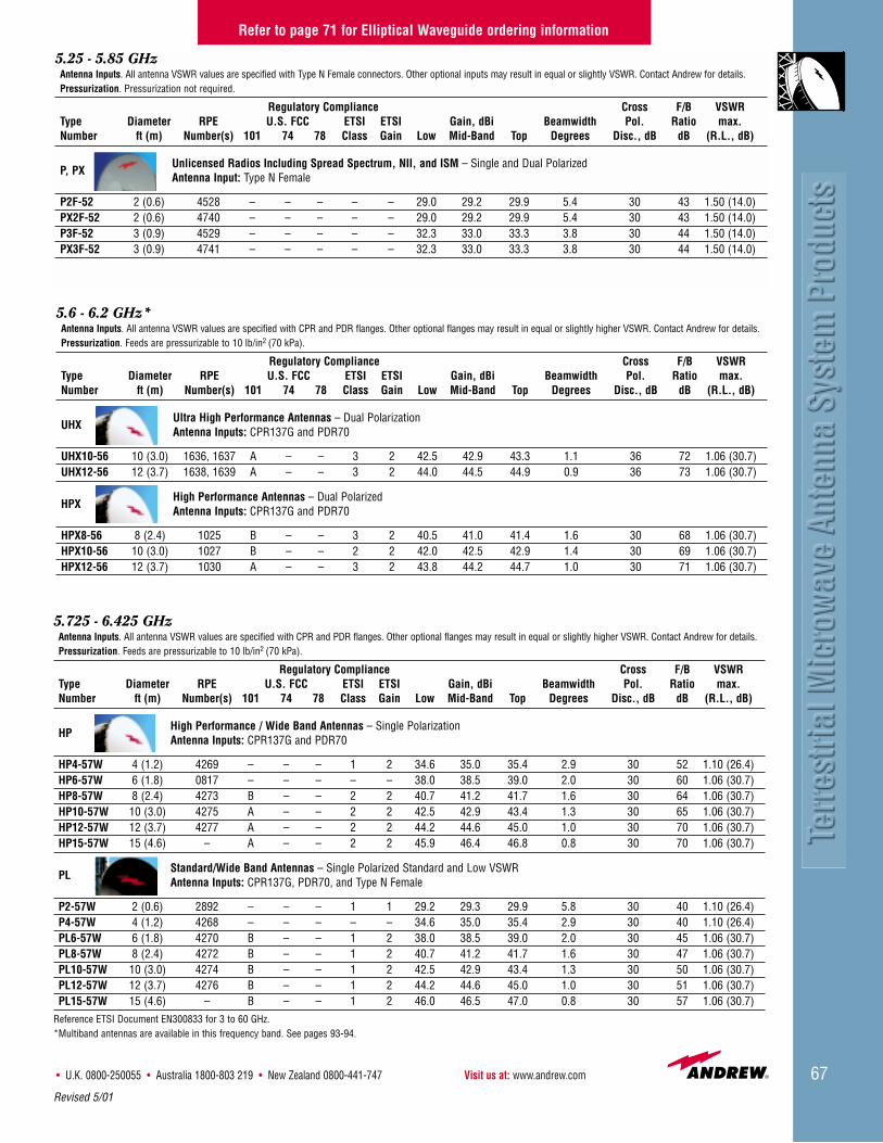
• U.K. 0800-250055 • Australia 1800-803 219 • New Zealand 0800-441-747 Visit us at: www.andrew.com 67
5.6 - 6.2 GHz*Antenna Inputs. All antenna VSWR values are specified with CPR and PDR flanges. Other optional flanges may result in equal or slightly higher VSWR. Contact Andrew for details.Pressurization. Feeds are pressurizable to 10 lb/in2 (70 kPa).
Regulatory Compliance Cross F/B VSWRType Diameter RPE U.S. FCC ETSI ETSI Gain, dBi Beamwidth Pol. Ratio max.Number ft (m) Number(s) 101 74 78 Class Gain Low Mid-Band Top Degrees Disc., dB dB (R.L., dB)
UHXUltra High Performance Antennas – Dual PolarizationAntenna Inputs: CPR137G and PDR70
UHX10-56 10 (3.0) 1636, 1637 A – – 3 2 42.5 42.9 43.3 1.1 36 72 1.06 (30.7)UHX12-56 12 (3.7) 1638, 1639 A – – 3 2 44.0 44.5 44.9 0.9 36 73 1.06 (30.7)
HPXHigh Performance Antennas – Dual PolarizedAntenna Inputs: CPR137G and PDR70
HPX8-56 8 (2.4) 1025 B – – 3 2 40.5 41.0 41.4 1.6 30 68 1.06 (30.7)HPX10-56 10 (3.0) 1027 B – – 2 2 42.0 42.5 42.9 1.4 30 69 1.06 (30.7)HPX12-56 12 (3.7) 1030 A – – 3 2 43.8 44.2 44.7 1.0 30 71 1.06 (30.7)
5.725 - 6.425 GHzAntenna Inputs. All antenna VSWR values are specified with CPR and PDR flanges. Other optional flanges may result in equal or slightly higher VSWR. Contact Andrew for details.Pressurization. Feeds are pressurizable to 10 lb/in2 (70 kPa).
Regulatory Compliance Cross F/B VSWRType Diameter RPE U.S. FCC ETSI ETSI Gain, dBi Beamwidth Pol. Ratio max.Number ft (m) Number(s) 101 74 78 Class Gain Low Mid-Band Top Degrees Disc., dB dB (R.L., dB)
HPHigh Performance / Wide Band Antennas – Single PolarizationAntenna Inputs: CPR137G and PDR70
HP4-57W 4 (1.2) 4269 – – – 1 2 34.6 35.0 35.4 2.9 30 52 1.10 (26.4)HP6-57W 6 (1.8) 0817 – – – – – 38.0 38.5 39.0 2.0 30 60 1.06 (30.7)HP8-57W 8 (2.4) 4273 B – – 2 2 40.7 41.2 41.7 1.6 30 64 1.06 (30.7)HP10-57W 10 (3.0) 4275 A – – 2 2 42.5 42.9 43.4 1.3 30 65 1.06 (30.7)HP12-57W 12 (3.7) 4277 A – – 2 2 44.2 44.6 45.0 1.0 30 70 1.06 (30.7)HP15-57W 15 (4.6) – A – – 2 2 45.9 46.4 46.8 0.8 30 70 1.06 (30.7)
PLStandard/Wide Band Antennas – Single Polarized Standard and Low VSWRAntenna Inputs: CPR137G, PDR70, and Type N Female
P2-57W 2 (0.6) 2892 – – – 1 1 29.2 29.3 29.9 5.8 30 40 1.10 (26.4)P4-57W 4 (1.2) 4268 – – – – – 34.6 35.0 35.4 2.9 30 40 1.10 (26.4)PL6-57W 6 (1.8) 4270 B – – 1 2 38.0 38.5 39.0 2.0 30 45 1.06 (30.7)PL8-57W 8 (2.4) 4272 B – – 1 2 40.7 41.2 41.7 1.6 30 47 1.06 (30.7)PL10-57W 10 (3.0) 4274 B – – 1 2 42.5 42.9 43.4 1.3 30 50 1.06 (30.7)PL12-57W 12 (3.7) 4276 B – – 1 2 44.2 44.6 45.0 1.0 30 51 1.06 (30.7)PL15-57W 15 (4.6) – B – – 1 2 46.0 46.5 47.0 0.8 30 57 1.06 (30.7)
Reference ETSI Document EN300833 for 3 to 60 GHz.*Multiband antennas are available in this frequency band. See pages 93-94.
5.25 - 5.85 GHzAntenna Inputs. All antenna VSWR values are specified with Type N Female connectors. Other optional inputs may result in equal or slightly VSWR. Contact Andrew for details.Pressurization. Pressurization not required.
Regulatory Compliance Cross F/B VSWRType Diameter RPE U.S. FCC ETSI ETSI Gain, dBi Beamwidth Pol. Ratio max.Number ft (m) Number(s) 101 74 78 Class Gain Low Mid-Band Top Degrees Disc., dB dB (R.L., dB)
P, PXUnlicensed Radios Including Spread Spectrum, NII, and ISM – Single and Dual PolarizedAntenna Input: Type N Female
P2F-52 2 (0.6) 4528 – – – – – 29.0 29.2 29.9 5.4 30 43 1.50 (14.0)PX2F-52 2 (0.6) 4740 – – – – – 29.0 29.2 29.9 5.4 30 43 1.50 (14.0)P3F-52 3 (0.9) 4529 – – – – – 32.3 33.0 33.3 3.8 30 44 1.50 (14.0)PX3F-52 3 (0.9) 4741 – – – – – 32.3 33.0 33.3 3.8 30 44 1.50 (14.0)
Refer to page 71 for Elliptical Waveguide ordering information
Revised 5/01
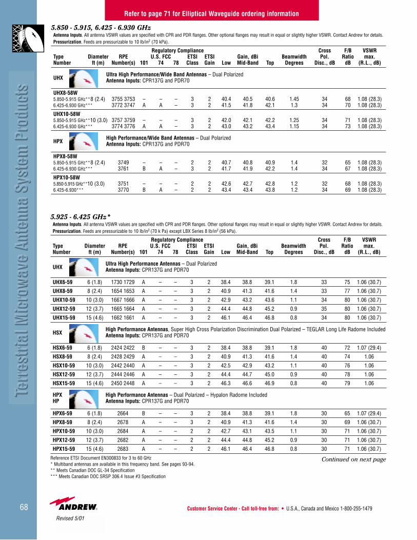
Customer Service Center - Call toll-free from: • U.S.A., Canada and Mexico 1-800-255-147968
5.850 - 5.915, 6.425 - 6.930 GHzAntenna Inputs. All antenna VSWR values are specified with CPR and PDR flanges. Other optional flanges may result in equal or slightly higher VSWR. Contact Andrew for details.Pressurization. Feeds are pressurizable to 10 lb/in2 (70 kPa).
Regulatory Compliance Cross F/B VSWRType Diameter RPE U.S. FCC ETSI ETSI Gain, dBi Beamwidth Pol. Ratio max.Number ft (m) Number(s) 101 74 78 Class Gain Low Mid-Band Top Degrees Disc., dB dB (R.L., dB)
UHXUltra High Performance/Wide Band Antennas – Dual PolarizedAntenna Inputs: CPR137G and PDR70
UHX8-58W5.850-5.915 GHz**8 (2.4) 3755 3753 – – – 3 2 40.4 40.5 40.6 1.45 34 68 1.08 (28.3)6.425-6.930 GHz*** 3772 3747 A A – 3 2 41.5 41.8 42.1 1.3 34 70 1.08 (28.3)
UHX10-58W5.850-5.915 GHz**10 (3.0) 3757 3759 – – – 3 2 42.0 42.1 42.2 1.25 34 71 1.08 (28.3)6.425-6.930 GHz*** 3774 3776 A A – 3 2 43.0 43.2 43.4 1.15 34 73 1.08 (28.3)
HPXHigh Performance/Wide Band Antennas – Dual PolarizedAntenna Inputs: CPR137G and PDR70
HPX8-58W5.850-5.915 GHz**8 (2.4) 3749 – – – 2 2 40.7 40.8 40.9 1.4 32 65 1.08 (28.3)6.425-6.930 GHz*** 3761 B A – 3 2 41.7 41.9 42.2 1.4 34 67 1.08 (28.3)
HPX10-58W5.850-5.915 GHz**10 (3.0) 3751 – – – 2 2 42.6 42.7 42.8 1.2 32 68 1.08 (28.3)6.425-6.930*** 3770 B A – 2 2 43.4 43.4 43.8 1.2 34 69 1.08 (28.3)
5.925 - 6.425 GHz*Antenna Inputs. All antenna VSWR values are specified with CPR and PDR flanges. Other optional flanges may result in equal or slightly higher VSWR. Contact Andrew for details.Pressurization. Feeds are pressurizable to 10 lb/in2 (70 k Pa) except LBX Series 8 lb/in2 (56 kPa).
Regulatory Compliance Cross F/B VSWRType Diameter RPE U.S. FCC ETSI ETSI Gain, dBi Beamwidth Pol. Ratio max.Number ft (m) Number(s) 101 74 78 Class Gain Low Mid-Band Top Degrees Disc., dB dB (R.L., dB)
UHXUltra High Performance Antennas – Dual PolarizedAntenna Inputs: CPR137G and PDR70
UHX6-59 6 (1.8) 1730 1729 A – – 3 2 38.4 38.8 39.1 1.8 33 75 1.06 (30.7)
UHX8-59 8 (2.4) 1654 1653 A – – 3 2 40.9 41.3 41.6 1.4 33 77 1.06 (30.7)
UHX10-59 10 (3.0) 1667 1666 A – – 3 2 42.9 43.2 43.6 1.1 34 80 1.06 (30.7)
UHX12-59 12 (3.7) 1665 1664 A – – 3 2 44.4 44.8 45.2 0.9 35 80 1.06 (30.7)
UHX15-59 15 (4.6) 1662 1661 A – – 3 2 46.1 46.4 46.8 0.8 34 80 1.06 (30.7)
HSXHigh Performance Antennas, Super High Cross Polarization Discrimination Dual Polarized – TEGLAR Long Life Radome Included Antenna Inputs: CPR137G and PDR70
HSX6-59 6 (1.8) 2424 2422 B – – 3 2 38.4 38.8 39.1 1.8 40 72 1.07 (29.4)
HSX8-59 8 (2.4) 2428 2429 A – – 3 2 40.9 41.3 41.6 1.4 40 74 1.06
HSX10-59 10 (3.0) 2442 2440 A – – 3 2 42.5 42.9 43.2 1.1 40 76 1.06
HSX12-59 12 (3.7) 2444 2446 A – – 3 2 44.4 44.7 45.0 0.9 40 78 1.06
HSX15-59 15 (4.6) 2450 2448 A – – 3 2 46.3 46.6 46.9 0.8 40 79 1.06
HPX High Performance Antennas – Dual Polarized – Hypalon Radome IncludedHP Antenna Inputs: CPR137G and PDR70
HPX6-59 6 (1.8) 2664 B – – 3 2 38.4 38.8 39.1 1.8 30 65 1.07 (29.4)
HPX8-59 8 (2.4) 2678 A – – 3 2 40.9 41.3 41.6 1.4 30 69 1.06 (30.7)
HPX10-59 10 (3.0) 2684 A – – 2 2 42.7 43.1 43.5 1.1 30 71 1.06 (30.7)
HPX12-59 12 (3.7) 2682 A – – 2 2 44.4 44.8 45.2 0.9 30 71 1.06 (30.7)
HPX15-59 15 (4.6) 2683 A – – 2 2 46.1 46.4 46.8 0.8 30 71 1.06 (30.7)
Reference ETSI Document EN300833 for 3 to 60 GHz* Multiband antennas are available in this frequency band. See pages 93-94.** Meets Canadian DOC GL-34 Specification*** Meets Canadian DOC SRSP 306.4 Issue #3 Specification
Continued on next page
Refer to page 71 for Elliptical Waveguide ordering information
Revised 5/01
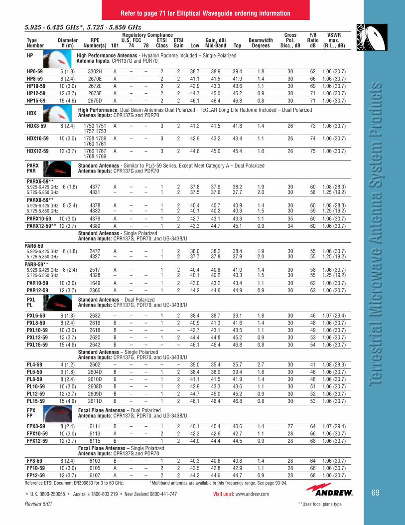
69
5.925 - 6.425 GHz*, 5.725 - 5.850 GHzRegulatory Compliance Cross F/B VSWR
Type Diameter RPE U.S. FCC ETSI ETSI Gain, dBi Beamwidth Pol. Ratio max.Number ft (m) Number(s) 101 74 78 Class Gain Low Mid-Band Top Degrees Disc., dB dB (R.L., dB)
HP High Performance Antennas - Hypalon Radome Included – Single PolarizedAntenna Inputs: CPR137G and PDR70
HP6-59 6 (1.8) 3302H A – – 2 2 38.7 38.9 39.4 1.8 30 62 1.06 (30.7)HP8-59 8 (2.4) 2670E A – – 2 2 41.1 41.5 41.9 1.4 30 66 1.06 (30.7)HP10-59 10 (3.0) 2672E A – – 2 2 42.9 43.3 43.6 1.1 30 69 1.06 (30.7)HP12-59 12 (3.7) 2673E A – – 2 2 44.7 45.0 45.2 0.9 30 71 1.06 (30.7)HP15-59 15 (4.6) 2675D A – – 2 2 46.1 46.4 46.8 0.8 30 71 1.06 (30.7)
HDXHigh Performance, Dual Beam Antennas Dual Polarized - TEGLAR Long Life Radome Included – Dual PolarizedAntenna Inputs: CPR137G and PDR70
HDX8-59 8 (2.4) 1750 1751 A – – 3 2 41.2 41.5 41.8 1.4 26 73 1.06 (30.7)1752 1753
HDX10-59 10 (3.0) 1758 1759 A – – 3 2 42.9 43.2 43.4 1.1 26 74 1.06 (30.7)1760 1761
HDX12-59 12 (3.7) 1766 1767 A – – 3 2 44.6 45.0 45.4 1.0 26 75 1.06 (30.7)1768 1769
PARX Standard Antennas - Similar to PL()-59 Series, Except Meet Category A – Dual PolarizedPAR Antenna Inputs: CPR137G and PDR70
PARX6-59**5.925-6.425 GHz 6 (1.8) 4377 A – – 1 2 37.8 37.9 38.2 1.9 30 60 1.08 (28.3)5.725-5.850 GHz 4331 – – – 1 2 37.5 37.6 37.7 2.0 30 58 1.25 (19.2)PARX8-59**5.925-6.425 GHz 8 (2.4) 4378 A – – 1 2 40.4 40.7 40.9 1.4 30 60 1.08 (28.3)5.725-5.850 GHz 4332 – – – 1 2 40.1 40.2 40.3 1.5 30 59 1.25 (19.2)PARX10-59 10 (3.0) 4379 A – – 1 2 42.7 43.1 43.3 1.1 35 60 1.06 (30.7)PARX12-59** 12 (3.7) 4380 A – – 1 2 43.3 44.7 45.1 0.9 34 60 1.06 (30.7)
Standard Antennas - Single PolarizedAntenna Inputs: CPR137G, PDR70, and UG-343B/U
PAR6-595.925-6.425 GHz 6 (1.8) 2472 A – – 1 2 38.0 38.2 38.4 1.9 30 55 1.06 (30.7)5.725-5.850 GHz 4327 – – – 1 2 37.7 37.8 37.9 2.0 30 55 1.25 (19.2)
PAR8-59**5.925-6.425 GHz 8 (2.4) 2517 A – – 1 2 40.4 40.8 41.0 1.4 30 58 1.06 (30.7)5.725-5.850 GHz 4328 – – – 1 2 40.1 40.2 40.3 1.5 30 55 1.25 (19.2)PAR10-59 10 (3.0) 1649 A – – 1 2 43.0 43.2 43.4 1.1 30 62 1.06 (30.7)PAR12-59 12 (3.7) 2366 A – – 1 2 44.2 44.6 44.9 0.9 30 63 1.06 (30.7)
PXL Standard Antennas – Dual PolarizedPL Antenna Inputs: CPR137G, PDR70, and UG-343B/U
PXL6-59 6 (1.8) 2632 – – – 1 2 38.4 38.7 39.1 1.8 30 46 1.07 (29.4)PXL8-59 8 (2.4) 2616 B – – 1 2 40.9 41.3 41.6 1.4 30 48 1.06 (30.7)PXL10-59 10 (3.0) 2618 B – – – – 42.7 43.1 43.5 1.1 30 49 1.06 (30.7)PXL12-59 12 (3.7) 2620 B – – 1 2 44.4 44.8 45.2 0.9 30 53 1.06 (30.7)PXL15-59 15 (4.6) 2642 B – – – – 46.1 46.4 46.8 0.8 30 54 1.06 (30.7)
Standard Antennas – Single PolarizedAntenna Inputs: CPR137G, PDR70, and UG-343B/U
PL4-59 4 (1.2) 2602 – – – – – 35.0 35.4 35.7 2.7 30 41 1.08 (28.3)PL6-59 6 (1.8) 2604D B – – 1 2 38.4 38.9 39.4 1.8 30 46 1.06 (30.7)PL8-59 8 (2.4) 2610D B – – 1 2 41.1 41.5 41.9 1.4 30 48 1.06 (30.7)PL10-59 10 (3.0) 2608D B – – 1 2 42.9 43.3 43.6 1.1 30 51 1.06 (30.7)PL12-59 12 (3.7) 2609D B – – 1 2 44.7 45.0 45.2 0.9 30 52 1.06 (30.7)PL15-59 15 (4.6) 2611D B – – 1 2 46.1 46.4 46.8 0.8 30 53 1.06 (30.7)
FPX Focal Plane Antennas – Dual PolarizedFP Antenna Inputs: CPR137G, PDR70, and UG-343B/U
FPX8-59 8 (2.4) 6111 B – – 1 2 40.1 40.4 40.6 1.4 27 64 1.07 (29.4)FPX10-59 10 (3.0) 6113 A – – 2 2 42.3 42.6 42.7 1.1 28 66 1.06 (30.7)FPX12-59 12 (3.7) 6115 B – – 1 2 44.0 44.4 44.5 0.9 28 68 1.06 (30.7)
Focal Plane Antennas – Single PolarizedAntenna Inputs: CPR137G and PDR70
FP8-59 8 (2.4) 6103 B – – 1 2 40.3 40.6 40.8 1.4 28 64 1.06 (30.7)FP10-59 10 (3.0) 6105 A – – 2 2 42.5 42.8 42.9 1.1 28 66 1.06 (30.7)FP12-59 12 (3.7) 6107 A – – 2 2 44.2 44.6 44.7 0.9 28 68 1.06 (30.7)
Reference ETSI Document EN300833 for 3 to 60 GHz; *Multiband antennas are available in this frequency range. See page 93-94.
**Uses focal plane type
• U.K. 0800-250055 • Australia 1800-803 219 • New Zealand 0800-441-747 Visit us at: www.andrew.com
Refer to page 71 for Elliptical Waveguide ordering information
Revised 5/01
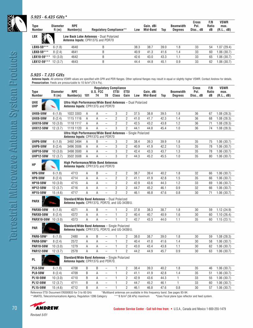
Customer Service Center - Call toll-free from: • U.S.A., Canada and Mexico 1-800-255-147970
5.925 - 7.125 GHzAntenna Inputs. All antenna VSWR values are specified with CPR and PDR flanges. Other optional flanges may result in equal or slightly higher VSWR. Contact Andrew for details.Pressurization. Feeds are pressurizable to 10 lb/in2 (70 k Pa).
Regulatory Compliance Cross F/B VSWRType Diameter RPE U.S. FCC ETSI ETSI Gain, dBi Beamwidth Pol. Ratio max.Number ft (m) Number(s) 101 74 78 Class Gain Low Mid-Band Top Degrees Disc., dB dB (R.L., dB)
UHX Ultra High Performance/Wide Band Antennas – Dual PolarizedUHP Antenna Inputs: CPR137G and PDR70
UHX6-59W 6 (1.8) 1022 3303 A A – 3 2 37.5 38.8 39.5 1.8 36 67 1.08 (28.3)UHX8-59W 8 (2.4) 1115 1116 A A – 2 2 41.0 41.7 42.3 1.4 36 68 1.08 (28.3)UHX10-59W 10 (3.0) 1118 1117 A A – 2 2 42.5 43.2 43.8 1.2 36 71 1.08 (28.3)UHX12-59W 12 (3.7) 1119 1120 A A – 3 2 44.1 44.8 45.4 1.0 36 74 1.08 (28.3)
Ultra High Performance/Wide Band Antennas – Single PolarizedAntenna Inputs: CPR137G and PDR70
UHP6-59W 6 (1.8) 3492 3494 A B – 3 2 38.4 39.3 39.9 1.8 35 75 1.06 (30.7)UHP8-59W 8 (2.4) 3496 3506 A A – 3 2 40.9 41.9 42.2 1.5 35 78 1.06 (30.7)UHP10-59W 10 (3.0) 3498 3500 A A – 3 2 42.4 43.3 43.7 1.3 35 78 1.06 (30.7)UHP12-59W 12 (3.7) 3502 3508 A A - 3 2 44.3 45.2 45.5 1.0 35 80 1.06 (30.7)
HPHigh Performance/Wide Band AntennasAntenna Inputs: CPR137G and PDR70
HP6-59W 6 (1.8) 4713 A B – 2 2 38.7 39.4 40.2 1.8 32 66 1.06 (30.7)HP8-59W 8 (2.4) 4714 A A – 2 2 41.1 41.9 42.8 1.5 35 66 1.06 (30.7)HP10-59W 10 (3.0) 4715 A A – 2 2 42.9 43.6 44.3 1.2 33 69 1.06 (30.7)HP12-59W 12 (3.7) 4716 A A – 2 2 44.7 45.2 46.1 0.9 32 66 1.06 (30.7)HP15-59W 15 (4.6) 4717 A A – 2 2 46.1 46.8 47.6 0.8 30 71 1.06 (30.7)
PARXStandard/Wide Band Antennas – Dual PolarizedAntenna Inputs: CPR137G, PDR70, and UG-343B/U.
PARX6-59W 6 (1.8) 4371 A B – 1 2 37.8 38.3 38.7 1.8 30 59 1.12 (24.9)PARX8-59W 8 (2.4) 4372 A A – 1 2 40.4 40.7 40.9 1.6 30 60 1.10 (26.4)PARX10-59W 10 (3.0) 4373 A A – 1 2 42.7 43.3 44.0 1.1 35 60 1.15 (23.1)
PARStandard/Wide Band Antennas – Single PolarizedAntenna Inputs: CPR137G, PDR70, and UG-343B/U.
PAR6-59W+ 6 (1.8) 2480 A B – 1 2 38.0 38.7 39.0 1.8 30 59 1.08 (28.3)PAR8-59W+ 8 (2.4) 2572 A A – 1 2 40.4 41.0 41.6 1.4 30 58 1.06 (30.7)PAR10-59W 10 (3.0) 1279 A A – 1 2 43.0 43.4 43.8 1.1 30 62 1.06 (30.7)PAR12-59W 12 (3.7) 2578 A A – 1 2 44.2 44.9 45.7 0.9 30 63 1.06 (30.7)
PLStandard/Wide Band Antennas – Single PolarizedAntenna Inputs: CPR137G and PDR70.
PL6-59W 6 (1.8) 4708 B B – 1 2 38.4 39.3 40.2 1.8 35 46 1.06 (30.7)PL8-59W 8 (2.4) 4709 B A – 1 2 41.1 41.9 42.8 1.4 35 51 1.06 (30.7)PL10-59W 10 (3.0) 4710 B A – 1 2 42.9 43.6 44.3 1 33 55 1.06 (30.7)PL12-59W 12 (3.7) 4711 B A – 1 2 44.7 45.2 46.1 1 33 60 1.06 (30.7)PL15-59W 15 (4.6) 4712 B A – 1 2 46.1 46.8 47.6 0.8 30 57 1.06 (30.7)
5.925 - 6.425 GHz*Cross F/B VSWR
Type Diameter RPE Gain, dBi Beamwidth Pol. Ratio max.Number ft (m) Number(s) Regulatory Compliance** Low Mid-Band Top Degrees Disc., dB dB (R.L., dB)
LBX Low Back Lobe Antennas - Dual PolarizedAntenna Inputs: CPR137G and PDR70
LBX6-59*** 6 (1.8) 4640 B 38.3 38.7 39.0 1.8 33 54 1.07 (29.4)LBX8-59*** 8 (2.4) 4641 B 40.9 41.3 41.6 1.4 33 60 1.06 (30.7)LBX10-59*** 10 (3.0) 4642 B 42.6 43.0 43.3 1.1 33 65 1.06 (30.7)LBX12-59*** 12 (3.7) 4643 B 44.4 44.8 45.1 0.9 33 62 1.06 (30.7)
Reference ETSI Document EN300833 for 3 to 60 GHz *Multiband antennas are available in this frequency band. See pages 93-94.**ANATEL Telecommunications Agency, Regulation 1286 Category ***8 lb/in2 (56 kPa) maximum +Uses Focal plane type reflector and feed system.
Revised 5/01
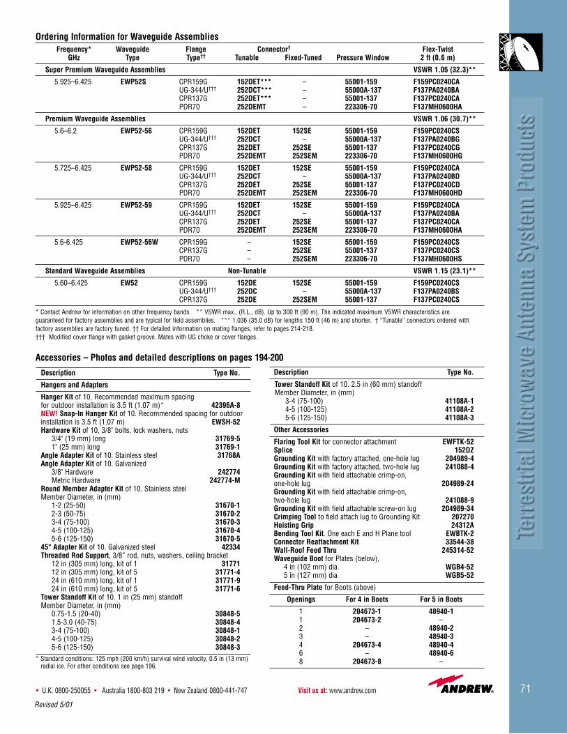
• U.K. 0800-250055 • Australia 1800-803 219 • New Zealand 0800-441-747 Visit us at: www.andrew.com 71
Ordering Information for Waveguide AssembliesFrequency* Waveguide Flange Connector† Flex-Twist
GHz Type Type†† Tunable Fixed-Tuned Pressure Window 2 ft (0.6 m)
Super Premium Waveguide Assemblies VSWR 1.05 (32.3)**
5.925–6.425 EWP52S CPR159G 152DET*** – 55001-159 F159PC0240CAUG-344/U††† 252DCT*** – 55000A-137 F137PA0240BACPR137G 252DET*** – 55001-137 F137PC0240CAPDR70 252DEMT – 223306-70 F137MH0600HA
Premium Waveguide Assemblies VSWR 1.06 (30.7)**
5.6–6.2 EWP52-56 CPR159G 152DET 152SE 55001-159 F159PC0240CSUG-344/U††† 252DCT – 55000A-137 F137PA0240BGCPR137G 252DET 252SE 55001-137 F137PC0240CGPDR70 252DEMT 252SEM 223306-70 F137MH0600HG
5.725–6.425 EWP52-58 CPR159G 152DET 152SE 55001-159 F159PC0240CAUG-344/U††† 252DCT – 55000A-137 F137PA0240BDCPR137G 252DET 252SE 55001-137 F137PC0240CDPDR70 252DEMT 252SEM 223306-70 F137MH0600HD
5.925–6.425 EWP52-59 CPR159G 152DET 152SE 55001-159 F159PC0240CAUG-344/U††† 252DCT – 55000A-137 F137PA0240BACPR137G 252DET 252SE 55001-137 F137PC0240CAPDR70 252DEMT 252SEM 223306-70 F137MH0600HA
5.6-6.425 EWP52-56W CPR159G – 152SE 55001-159 F159PC0240CSCPR137G – 252SE 55001-137 F137PC0240CSPDR70 – 252SEM 223306-70 F137MH0600HS
Standard Waveguide Assemblies Non-Tunable VSWR 1.15 (23.1)**
5.60–6.425 EW52 CPR159G 152DE 152SE 55001-159 F159PC0240CSUG-344/U††† 252DC – 55000A-137 F137PA0240BSCPR137G 252DE 252SEM 55001-137 F137PC0240CS
* Contact Andrew for information on other frequency bands. ** VSWR max., (R.L., dB). Up to 300 ft (90 m). The indicated maximum VSWR characteristics are guaranteed for factory assemblies and are typical for field assemblies. *** 1.036 (35.0 dB) for lengths 150 ft (46 m) and shorter. † “Tunable” connectors ordered with factory assemblies are factory tuned. †† For detailed information on mating flanges, refer to pages 214-218.††† Modified cover flange with gasket groove. Mates with UG choke or cover flanges.
Description Type No.
Hangers and Adapters
Hanger Kit of 10, Recommended maximum spacingfor outdoor installation is 3.5 ft (1.07 m)* 42396A-8NEW! Snap-In Hanger Kit of 10. Recommended spacing for outdoor installation is 3.5 ft (1.07 m) EWSH-52Hardware Kit of 10, 3/8" bolts, lock washers, nuts
3/4" (19 mm) long 31769-51" (25 mm) long 31769-1
Angle Adapter Kit of 10. Stainless steel 31768AAngle Adapter Kit of 10. Galvanized
3/8" Hardware 242774Metric Hardware 242774-M
Round Member Adapter Kit of 10. Stainless steelMember Diameter, in (mm)
1-2 (25-50) 31670-12-3 (50-75) 31670-23-4 (75-100) 31670-34-5 (100-125) 31670-45-6 (125-150) 31670-5
45° Adapter Kit of 10. Galvanized steel 42334Threaded Rod Support, 3/8” rod, nuts, washers, ceiling bracket
12 in (305 mm) long, kit of 1 3177112 in (305 mm) long, kit of 5 31771-424 in (610 mm) long, kit of 1 31771-924 in (610 mm) long, kit of 5 31771-6
Tower Standoff Kit of 10. 1 in (25 mm) standoffMember Diameter, in (mm)
0.75-1.5 (20-40) 30848-51.5-3.0 (40-75) 30848-43-4 (75-100) 30848-14-5 (100-125) 30848-25-6 (125-150) 30848-3
* Standard conditions: 125 mph (200 km/h) survival wind velocity, 0.5 in (13 mm) radial ice. For other conditions see page 196.
Description Type No.
Tower Standoff Kit of 10. 2.5 in (60 mm) standoffMember Diameter, in (mm)
3-4 (75-100) 41108A-14-5 (100-125) 41108A-25-6 (125-150) 41108A-3
Other Accessories
Flaring Tool Kit for connector attachment EWFTK-52Splice 152DZGrounding Kit with factory attached, one-hole lug 204989-4Grounding Kit with factory attached, two-hole lug 241088-4Grounding Kit with field attachable crimp-on, one-hole lug 204989-24Grounding Kit with field attachable crimp-on, two-hole lug 241088-9Grounding Kit with field attachable screw-on lug 204989-34Crimping Tool to field attach lug to Grounding Kit 207270Hoisting Grip 24312ABending Tool Kit. One each E and H Plane tool EWBTK-2Connector Reattachment Kit 33544-38Wall-Roof Feed Thru 245314-52Waveguide Boot for Plates (below),
4 in (102 mm) dia. WGB4-525 in (127 mm) dia WGB5-52
Feed-Thru Plate for Boots (above)
Openings For 4 in Boots For 5 in Boots
1 204673-1 48940-11 204673-2 –2 – 48940-23 – 48940-34 204673-4 48940-46 – 48940-68 204673-8 –
Accessories – Photos and detailed descriptions on pages 194-200
Revised 5/01
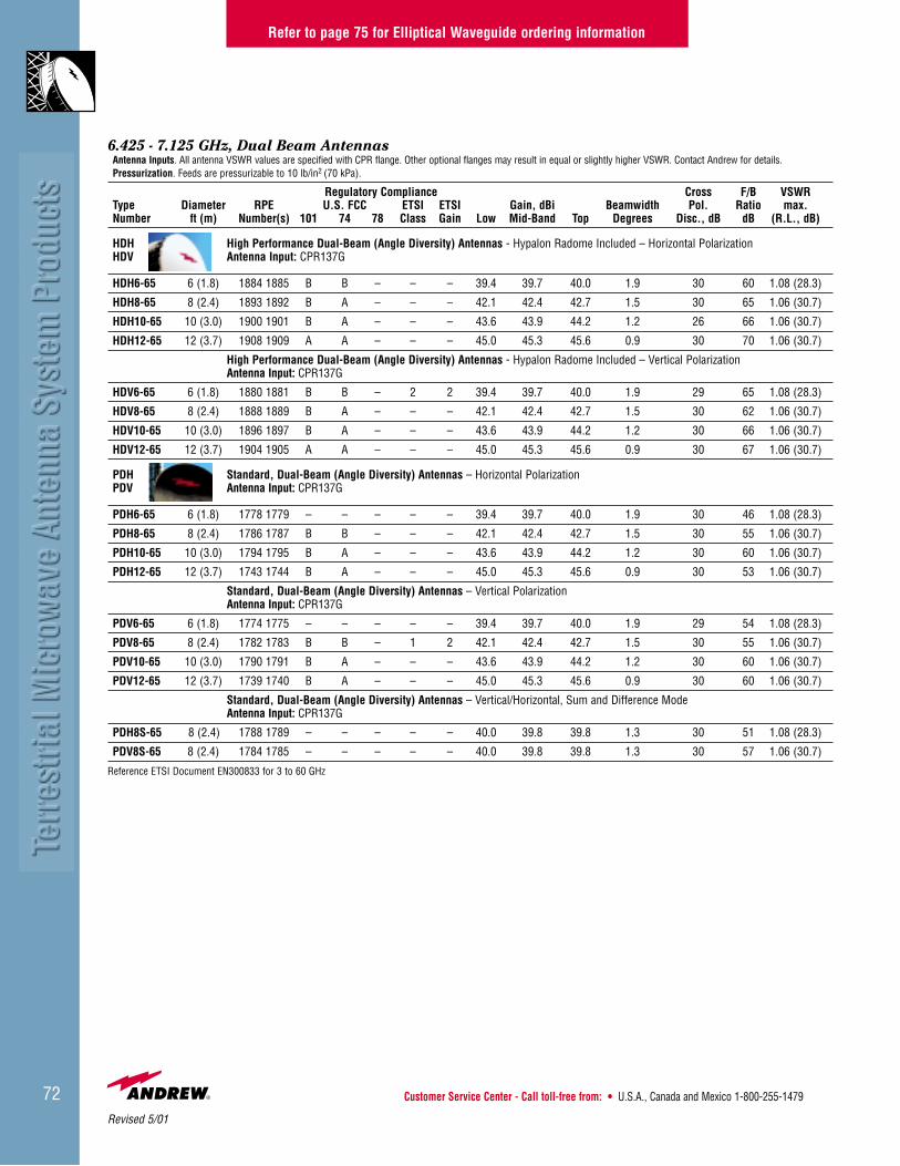
Customer Service Center - Call toll-free from: • U.S.A., Canada and Mexico 1-800-255-147972
6.425 - 7.125 GHz, Dual Beam AntennasAntenna Inputs. All antenna VSWR values are specified with CPR flange. Other optional flanges may result in equal or slightly higher VSWR. Contact Andrew for details.Pressurization. Feeds are pressurizable to 10 lb/in2 (70 kPa).
Regulatory Compliance Cross F/B VSWRType Diameter RPE U.S. FCC ETSI ETSI Gain, dBi Beamwidth Pol. Ratio max.Number ft (m) Number(s) 101 74 78 Class Gain Low Mid-Band Top Degrees Disc., dB dB (R.L., dB)
HDH High Performance Dual-Beam (Angle Diversity) Antennas - Hypalon Radome Included – Horizontal PolarizationHDV Antenna Input: CPR137G
HDH6-65 6 (1.8) 1884 1885 B B – – – 39.4 39.7 40.0 1.9 30 60 1.08 (28.3)
HDH8-65 8 (2.4) 1893 1892 B A – – – 42.1 42.4 42.7 1.5 30 65 1.06 (30.7)
HDH10-65 10 (3.0) 1900 1901 B A – – – 43.6 43.9 44.2 1.2 26 66 1.06 (30.7)
HDH12-65 12 (3.7) 1908 1909 A A – – – 45.0 45.3 45.6 0.9 30 70 1.06 (30.7)
High Performance Dual-Beam (Angle Diversity) Antennas - Hypalon Radome Included – Vertical PolarizationAntenna Input: CPR137G
HDV6-65 6 (1.8) 1880 1881 B B – 2 2 39.4 39.7 40.0 1.9 29 65 1.08 (28.3)
HDV8-65 8 (2.4) 1888 1889 B A – – – 42.1 42.4 42.7 1.5 30 62 1.06 (30.7)
HDV10-65 10 (3.0) 1896 1897 B A – – – 43.6 43.9 44.2 1.2 30 66 1.06 (30.7)
HDV12-65 12 (3.7) 1904 1905 A A – – – 45.0 45.3 45.6 0.9 30 67 1.06 (30.7)
PDH Standard, Dual-Beam (Angle Diversity) Antennas – Horizontal PolarizationPDV Antenna Input: CPR137G
PDH6-65 6 (1.8) 1778 1779 – – – – – 39.4 39.7 40.0 1.9 30 46 1.08 (28.3)
PDH8-65 8 (2.4) 1786 1787 B B – – – 42.1 42.4 42.7 1.5 30 55 1.06 (30.7)
PDH10-65 10 (3.0) 1794 1795 B A – – – 43.6 43.9 44.2 1.2 30 60 1.06 (30.7)
PDH12-65 12 (3.7) 1743 1744 B A – – – 45.0 45.3 45.6 0.9 30 53 1.06 (30.7)
Standard, Dual-Beam (Angle Diversity) Antennas – Vertical PolarizationAntenna Input: CPR137G
PDV6-65 6 (1.8) 1774 1775 – – – – – 39.4 39.7 40.0 1.9 29 54 1.08 (28.3)
PDV8-65 8 (2.4) 1782 1783 B B – 1 2 42.1 42.4 42.7 1.5 30 55 1.06 (30.7)
PDV10-65 10 (3.0) 1790 1791 B A – – – 43.6 43.9 44.2 1.2 30 60 1.06 (30.7)
PDV12-65 12 (3.7) 1739 1740 B A – – – 45.0 45.3 45.6 0.9 30 60 1.06 (30.7)
Standard, Dual-Beam (Angle Diversity) Antennas – Vertical/Horizontal, Sum and Difference ModeAntenna Input: CPR137G
PDH8S-65 8 (2.4) 1788 1789 – – – – – 40.0 39.8 39.8 1.3 30 51 1.08 (28.3)
PDV8S-65 8 (2.4) 1784 1785 – – – – – 40.0 39.8 39.8 1.3 30 57 1.06 (30.7)
Reference ETSI Document EN300833 for 3 to 60 GHz
Refer to page 75 for Elliptical Waveguide ordering information
Revised 5/01
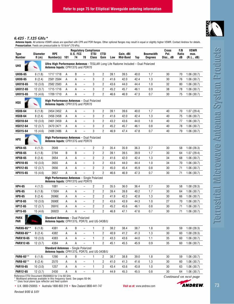
• U.K. 0800-250055 • Australia 1800-803 219 • New Zealand 0800-441-747 Visit us at: www.andrew.com 73
6.425 - 7.125 GHz*Antenna Inputs. All antenna VSWR values are specified with CPR and PDR flanges. Other optional flanges may result in equal or slightly higher VSWR. Contact Andrew for details.Pressurization. Feeds are pressurizable to 10 lb/in2 (70 kPa).
Regulatory Compliance Cross F/B VSWRType Diameter RPE U.S. FCC ETSI ETSI Gain, dBi Beamwidth Pol. Ratio max.Number ft (m) Number(s) 101 74 78 Class Gain Low Mid-Band Top Degrees Disc., dB dB (R.L., dB)
UHXUltra High Performance Antennas - TEGLAR Long Life Radome Included – Dual PolarizedAntenna Inputs: CPR137G and PDR70
UHX6-65 6 (1.8) 1717 1718 A B – 3 2 39.1 39.5 40.0 1.7 30 70 1.06 (30.7)
UHX8-65 8 (2.4) 2581 2584 A A – 3 2 41.6 42.0 42.4 1.3 30 76 1.06 (30.7)
UHX10-65 10 (3.0) 2582 2583 A A – 3 2 43.6 44.0 44.4 1.0 32 80 1.06 (30.7)
UHX12-65 12 (3.7) 1715 1716 A A – 3 2 45.2 45.7 46.1 0.9 38 78 1.06 (30.7)
UHX15-65 15 (4.6) 1709 1710 A A – 2 2 46.6 46.9 47.3 0.7 30 75 1.06 (30.7)
HSXHigh Performance Antennas – Dual PolarizedAntenna Inputs: CPR137G and PDR70
HSX6-64 6 (1.8) 2454 2452 A A – 3 2 39.1 39.6 40.0 1.7 40 70 1.07 (29.4)
HSX8-64 8 (2.4) 2456 2458 A A – 3 2 41.6 42.0 42.4 1.3 40 75 1.06 (30.7)
HSX10-64 10 (3.0) 2461 2459 A A – 3 2 43.2 43.6 44.0 1.0 40 77 1.06 (30.7)
HSX12-64 12 (3.7) 2470 2471 A A – 3 2 45.2 45.7 46.1 0.8 40 78 1.06 (30.7)
HSX15-64 15 (4.6) 2488 2486 A A – 3 2 46.9 47.4 47.8 0.7 40 79 1.06 (30.7)
HPXHigh Performance Antennas – Dual PolarizedAntenna Inputs: CPR137G and PDR70
HPX4-65 4 (1.2) 2649 – – – 2 2 35.4 35.9 36.3 2.7 30 58 1.08 (28.3)
HPX6-65 6 (1.8) 2794 B B – 2 2 39.1 39.5 39.9 1.7 30 64 1.07 (29.4)
HPX8-65 8 (2.4) 2654 A A – 2 2 41.6 42.0 42.4 1.3 34 68 1.06 (30.7)
HPX10-65 10 (3.0) 2655 A A – 3 2 43.6 44.0 44.4 1.0 34 70 1.06 (30.7)
HPX12-65 12 (3.7) 2656 A A – 2 2 45.0 45.4 45.9 0.8 30 71 1.06 (30.7)
HPX15-65 15 (4.6) 2657 A A – 2 2 46.6 46.9 47.3 0.7 30 71 1.06 (30.7)
High Performance Antennas – Single PolarizedAntenna Inputs: CPR137G and PDR70
HP4-65 4 (1.2) 1081 – – – 2 2 35.5 36.0 36.4 2.7 30 58 1.08 (28.3)
HP6-65 6 (1.8) 1700H A A – 2 2 39.4 39.8 40.2 1.7 30 64 1.06 (30.7)
HP8-65 8 (2.4) 2696E A A – 2 2 41.9 42.3 42.8 1.3 30 66 1.06 (30.7)
HP10-65 10 (3.0) 2690E A A – 2 2 43.6 43.9 44.3 1.0 27 70 1.06 (30.7)
HP12-65 12 (3.7) 2691E A A – 2 2 45.2 45.6 46.1 0.8 30 71 1.06 (30.7)
HP15-65 15 (4.6) 2692D A A – 2 2 46.8 47.1 47.6 0.7 30 71 1.06 (30.7)
PARX Standard Antennas – Dual PolarizedPAR Antenna Inputs: CPR137G, PDR70, and UG-343B/U
PARX6-65** 6 (1.8) 4381 A B – 1 2 38.2 38.4 38.7 1.8 30 59 1.08 (28.3)
PARX8-65** 8 (2.4) 4382 A A – 1 2 40.9 41.2 41.3 1.3 30 60 1.08 (28.3)
PARX10-65 10 (3.0) 4383 A A – 1 2 43.3 43.6 44.0 1.1 35 60 1.06 (30.7)
PARX12-65 12 (3.7) 4384 A A – 1 2 45.1 45.5 45.9 0.9 35 60 1.06 (30.7)
Standard Antennas – Single PolarizedAntenna Inputs: CPR137G, PDR70, and UG-343B/U
PAR6-65** 6 (1.8) 1290 A B – 1 2 38.7 38.8 39.0 1.8 30 59 1.06 (30.7)
PAR8-65** 8 (2.4) 2570 A A – 1 2 41.0 41.3 41.6 1.3 30 60 1.06 (30.7)
PAR10-65 10 (3.0) 1257 A A – 1 2 43.4 43.6 43.8 1.0 30 63 1.06 (30.7)
PAR12-65 12 (3.7) 2430 A A – 1 2 44.9 45.3 45.5 0.8 30 64 1.06 (30.7)Reference ETSI Document EN300833 for 3 to 60 GHz* Multiband antennas available in this frequency band. See pages 93-94.** Uses focal plane type reflector and feed system
Continued on next page
Refer to page 75 for Elliptical Waveguide ordering information
Revised 9/00 & 5/01
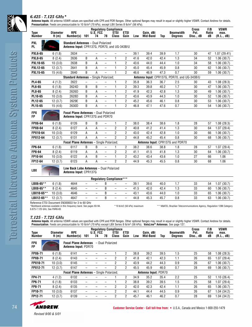
Customer Service Center - Call toll-free from: • U.S.A., Canada and Mexico 1-800-255-147974
6.425 - 7.125 GHz*Antenna Inputs. All antenna VSWR values are specified with CPR and PDR flanges. Other optional flanges may result in equal or slightly higher VSWR. Contact Andrew for details.Pressurization. Feeds are pressurizable to 10 lb/in2 (70 kPa), except LBX Series 8 lb/in2 (56 kPa).
Regulatory Compliance Cross F/B VSWRType Diameter RPE U.S. FCC ETSI ETSI Gain, dBi Beamwidth Pol. Ratio max.Number ft (m) Number(s) 101 74 78 Class Gain Low Mid-Band Top Degrees Disc., dB dB (R.L., dB)
PXL Standard Antennas – Dual PolarizedPL Antenna Input: CPR137G, PDR70, and UG-343B/U
PXL6-65 6 (1.8) 2634 – – – – – 39.1 39.4 39.9 1.7 30 47 1.07 (29.41)PXL8-65 8 (2.4) 2636 B A – 1 2 41.6 42.0 42.4 1.3 34 52 1.06 (30.7)PXL10-65 10 (3.0) 2638 B A – 1 2 43.6 44.0 44.4 1.0 34 58 1.06 (30.7)PXL12-65 12 (3.7) 2641 B A – 1 2 45.0 45.4 45.9 0.8 30 62 1.06 (30.7)PXL15-65 15 (4.6) 2640 B A – 1 2 46.6 46.9 47.3 0.7 30 59 1.06 (30.7)
Standard Antennas – Single Polarized; Antenna Input: CPR137G, PDR70, and UG-343B/UPL4-65 4 (1.2) 2622 – – – 1 2 35.8 36.3 36.7 2.5 30 43 1.08 (28.3)PL6-65 6 (1.8) 2624D B B – 1 2 39.3 39.8 40.2 1.7 30 47 1.06 (30.7)PL8-65 8 (2.4) 2626D B A – 1 2 41.9 42.3 42.8 1.3 30 49 1.06 (30.7)PL10-65 10 (3.0) 2628D B A – 1 2 43.6 43.9 44.3 1.0 30 52 1.06 (30.7)PL12-65 12 (3.7) 2629E B A – 1 2 45.2 45.6 46.1 0.8 30 53 1.06 (30.7)PL15-65 15 (4.6) 2630D B A – 1 2 46.8 47.1 47.6 0.7 30 54 1.06 (30.7)
FPX Focal Plane Antennas – Dual PolarizedFP Antenna Input: CPR137G and PDR70
FPX6-64 6 (1.8) 6126 B B – 1 2 38.0 38.4 38.6 1.8 28 57 1.08 (28.3)FPX8-64 8 (2.4) 6127 A A – 2 2 40.8 41.2 41.4 1.3 30 64 1.07 (29.4)FPX10-64 10 (3.0) 6129 A A – 2 2 43.0 42.4 42.8 1.0 30 66 1.06 (30.7)FPX12-64 12 (3.7) 6131 A A – 2 2 44.8 45.2 45.4 0.8 30 68 1.06 (30.7)
Focal Plane Antennas – Single Polarized; Antenna Input: CPR137G and PDR70FP6-64 6 (1.8) 6117 B B – 1 2 38.2 38.6 38.8 1.8 28 57 1.07 (29.4)FP8-64 8 (2.4) 6119 A A – 2 2 41.1 41.5 41.8 1.3 30 64 1.06 (30.7)FP10-64 10 (3.0) 6122 A B – 1 2 43.2 43.4 43.6 1.0 27 66 1.06FP12-64 12 (3.7) 6123 A A – 2 2 44.9 45.3 45.5 0.8 30 68 1.06
LBXLow Back Lobe Antennas – Dual PolarizedAntenna Input: CPR137G
Regulatory Compliance***LBX6-65** 6 (1.8) 4644 – – B – – 39.1 39.6 40.0 1.7 33 54 1.07 (30.7)LBX8-65** 8 (2.4) 4645 – – B – – 41.5 42.0 42.4 1.3 33 60 1.06 (30.7)LBX10-65** 10 (3.0) 4646 – – B – – 43.1 43.6 44.0 1.0 33 65 1.06 (30.7)LBX12-65** 12 (3.7) 4647 – – B – – 44.8 45.3 45.7 0.8 33 63 1.06 (30.7)
Reference ETSI Document EN300833 for 3 to 60 GHz*Multiband antennas available in this frequency band. See pages 93-94. **8 lb/in2 (56 kPa) maximum ***ANATEL Brazilian Telecommunications Agency, Regulation 1286 Category6.875-7.125 GHz, See PAR6-65
Revised 9/00 & 5/01
7.125 - 7.725 GHzAntenna Inputs. All antenna VSWR values are specified with CPR and PDR flanges. Other optional flanges may result in equal or slightly higher VSWR. Contact Andrew for details.Pressurization. Feeds are pressurizable to 10 lb/in2 (70 kPa) except LBX Series 8 lb/in2 (56 kPa). ValuLine® Antennas. See page 127.
Regulatory Compliance Cross F/B VSWRType Diameter RPE U.S. FCC ETSI ETSI Gain, dBi Beamwidth Pol. Ratio max.Number ft (m) Number(s) 101 74 78 Class Gain Low Mid-Band Top Degrees Disc., dB dB (R.L., dB)
FPX Focal Plane Antennas – Dual PolarizedFP Antenna Input: PDR70
FPX6-71 6 (1.8) 6141 – – – 1 2 38.8 39.2 39.5 1.5 25 58 1.08 (28.3)FPX8-71 8 (2.4) 6143 – – – 2 2 41.8 42.1 42.3 1.1 26 65 1.07 (29.4)FPX10-71 10 (3.0) 6145 – – – 2 2 43.9 44.2 44.3 0.9 26 67 1.06 (30.7)FPX12-71 12 (3.7) 6147 – – – 2 2 45.5 45.9 46.0 0.7 28 69 1.06 (30.7)
Focal Plane Antennas – Single Polarized; Antenna Input: PDR70FP4-71 4 (1.2) 6132 – – – 1 2 34.9 35.2 35.4 2.2 25 52 1.10 (26.4)FP6-71 6 (1.8) 6133 – – – 1 2 38.8 39.2 39.5 1.5 25 58 1.07 (29.4)FP8-71 8 (2.4) 6135 – – – 2 2 42.0 42.3 42.4 1.1 26 65 1.06 (30.7)FP10-71 10 (3.0) 6137 – – – 2 2 44.1 44.4 44.5 0.9 26 67 1.04 (34.2)FP12-71 12 (3.7) 6139 – – – 2 2 45.7 46.1 46.2 0.7 28 69 1.04 (34.2)
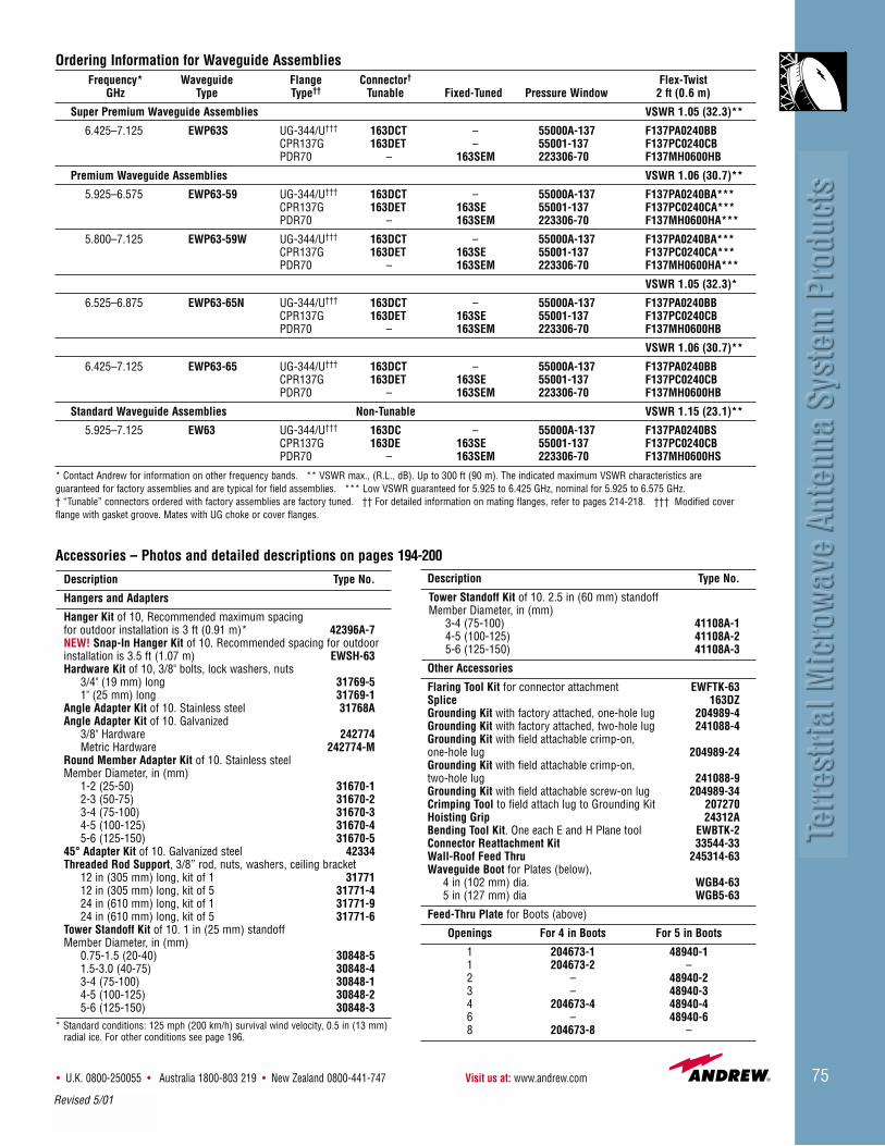
• U.K. 0800-250055 • Australia 1800-803 219 • New Zealand 0800-441-747 Visit us at: www.andrew.com 75
Ordering Information for Waveguide AssembliesFrequency* Waveguide Flange Connector† Flex-Twist
GHz Type Type†† Tunable Fixed-Tuned Pressure Window 2 ft (0.6 m)
Super Premium Waveguide Assemblies VSWR 1.05 (32.3)**
6.425–7.125 EWP63S UG-344/U††† 163DCT – 55000A-137 F137PA0240BBCPR137G 163DET – 55001-137 F137PC0240CBPDR70 – 163SEM 223306-70 F137MH0600HB
Premium Waveguide Assemblies VSWR 1.06 (30.7)**
5.925–6.575 EWP63-59 UG-344/U††† 163DCT – 55000A-137 F137PA0240BA***CPR137G 163DET 163SE 55001-137 F137PC0240CA***PDR70 – 163SEM 223306-70 F137MH0600HA***
5.800–7.125 EWP63-59W UG-344/U††† 163DCT – 55000A-137 F137PA0240BA***CPR137G 163DET 163SE 55001-137 F137PC0240CA***PDR70 – 163SEM 223306-70 F137MH0600HA***
VSWR 1.05 (32.3)*
6.525–6.875 EWP63-65N UG-344/U††† 163DCT – 55000A-137 F137PA0240BBCPR137G 163DET 163SE 55001-137 F137PC0240CBPDR70 – 163SEM 223306-70 F137MH0600HB
VSWR 1.06 (30.7)**
6.425–7.125 EWP63-65 UG-344/U††† 163DCT – 55000A-137 F137PA0240BBCPR137G 163DET 163SE 55001-137 F137PC0240CBPDR70 – 163SEM 223306-70 F137MH0600HB
Standard Waveguide Assemblies Non-Tunable VSWR 1.15 (23.1)**
5.925–7.125 EW63 UG-344/U††† 163DC – 55000A-137 F137PA0240BSCPR137G 163DE 163SE 55001-137 F137PC0240CBPDR70 – 163SEM 223306-70 F137MH0600HS
* Contact Andrew for information on other frequency bands. ** VSWR max., (R.L., dB). Up to 300 ft (90 m). The indicated maximum VSWR characteristics are guaranteed for factory assemblies and are typical for field assemblies. *** Low VSWR guaranteed for 5.925 to 6.425 GHz, nominal for 5.925 to 6.575 GHz. † “Tunable” connectors ordered with factory assemblies are factory tuned. †† For detailed information on mating flanges, refer to pages 214-218. ††† Modified coverflange with gasket groove. Mates with UG choke or cover flanges.
Description Type No.
Hangers and Adapters
Hanger Kit of 10, Recommended maximum spacingfor outdoor installation is 3 ft (0.91 m)* 42396A-7NEW! Snap-In Hanger Kit of 10. Recommended spacing for outdoor installation is 3.5 ft (1.07 m) EWSH-63Hardware Kit of 10, 3/8" bolts, lock washers, nuts
3/4" (19 mm) long 31769-51" (25 mm) long 31769-1
Angle Adapter Kit of 10. Stainless steel 31768AAngle Adapter Kit of 10. Galvanized
3/8" Hardware 242774Metric Hardware 242774-M
Round Member Adapter Kit of 10. Stainless steelMember Diameter, in (mm)
1-2 (25-50) 31670-12-3 (50-75) 31670-23-4 (75-100) 31670-34-5 (100-125) 31670-45-6 (125-150) 31670-5
45° Adapter Kit of 10. Galvanized steel 42334Threaded Rod Support, 3/8” rod, nuts, washers, ceiling bracket
12 in (305 mm) long, kit of 1 3177112 in (305 mm) long, kit of 5 31771-424 in (610 mm) long, kit of 1 31771-924 in (610 mm) long, kit of 5 31771-6
Tower Standoff Kit of 10. 1 in (25 mm) standoffMember Diameter, in (mm)
0.75-1.5 (20-40) 30848-51.5-3.0 (40-75) 30848-43-4 (75-100) 30848-14-5 (100-125) 30848-25-6 (125-150) 30848-3
* Standard conditions: 125 mph (200 km/h) survival wind velocity, 0.5 in (13 mm) radial ice. For other conditions see page 196.
Description Type No.
Tower Standoff Kit of 10. 2.5 in (60 mm) standoffMember Diameter, in (mm)
3-4 (75-100) 41108A-14-5 (100-125) 41108A-25-6 (125-150) 41108A-3
Other Accessories
Flaring Tool Kit for connector attachment EWFTK-63Splice 163DZGrounding Kit with factory attached, one-hole lug 204989-4Grounding Kit with factory attached, two-hole lug 241088-4Grounding Kit with field attachable crimp-on, one-hole lug 204989-24Grounding Kit with field attachable crimp-on, two-hole lug 241088-9Grounding Kit with field attachable screw-on lug 204989-34Crimping Tool to field attach lug to Grounding Kit 207270Hoisting Grip 24312ABending Tool Kit. One each E and H Plane tool EWBTK-2Connector Reattachment Kit 33544-33Wall-Roof Feed Thru 245314-63Waveguide Boot for Plates (below),
4 in (102 mm) dia. WGB4-635 in (127 mm) dia WGB5-63
Feed-Thru Plate for Boots (above)
Openings For 4 in Boots For 5 in Boots
1 204673-1 48940-11 204673-2 –2 – 48940-23 – 48940-34 204673-4 48940-46 – 48940-68 204673-8 –
Accessories – Photos and detailed descriptions on pages 194-200
Revised 5/01
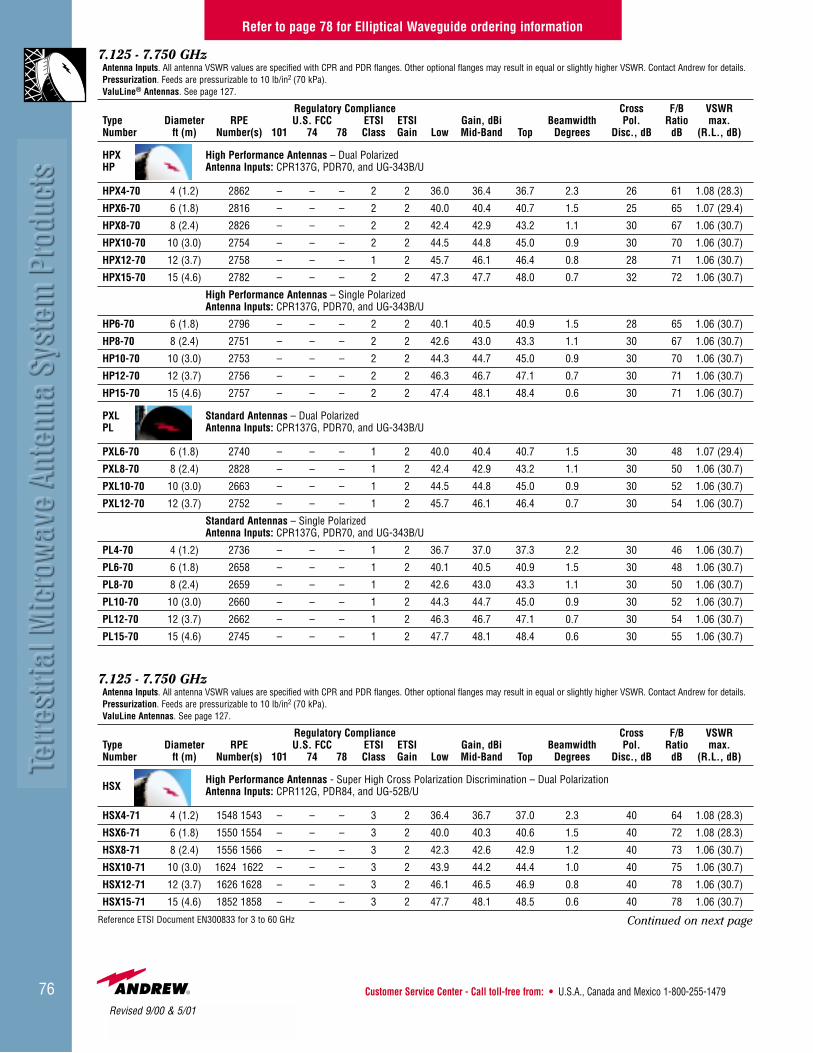
Customer Service Center - Call toll-free from: • U.S.A., Canada and Mexico 1-800-255-147976
7.125 - 7.750 GHzAntenna Inputs. All antenna VSWR values are specified with CPR and PDR flanges. Other optional flanges may result in equal or slightly higher VSWR. Contact Andrew for details.Pressurization. Feeds are pressurizable to 10 lb/in2 (70 kPa).ValuLine® Antennas. See page 127.
Regulatory Compliance Cross F/B VSWRType Diameter RPE U.S. FCC ETSI ETSI Gain, dBi Beamwidth Pol. Ratio max.Number ft (m) Number(s) 101 74 78 Class Gain Low Mid-Band Top Degrees Disc., dB dB (R.L., dB)
HPX High Performance Antennas – Dual PolarizedHP Antenna Inputs: CPR137G, PDR70, and UG-343B/U
HPX4-70 4 (1.2) 2862 – – – 2 2 36.0 36.4 36.7 2.3 26 61 1.08 (28.3)
HPX6-70 6 (1.8) 2816 – – – 2 2 40.0 40.4 40.7 1.5 25 65 1.07 (29.4)
HPX8-70 8 (2.4) 2826 – – – 2 2 42.4 42.9 43.2 1.1 30 67 1.06 (30.7)
HPX10-70 10 (3.0) 2754 – – – 2 2 44.5 44.8 45.0 0.9 30 70 1.06 (30.7)
HPX12-70 12 (3.7) 2758 – – – 1 2 45.7 46.1 46.4 0.8 28 71 1.06 (30.7)
HPX15-70 15 (4.6) 2782 – – – 2 2 47.3 47.7 48.0 0.7 32 72 1.06 (30.7)
High Performance Antennas – Single PolarizedAntenna Inputs: CPR137G, PDR70, and UG-343B/U
HP6-70 6 (1.8) 2796 – – – 2 2 40.1 40.5 40.9 1.5 28 65 1.06 (30.7)
HP8-70 8 (2.4) 2751 – – – 2 2 42.6 43.0 43.3 1.1 30 67 1.06 (30.7)
HP10-70 10 (3.0) 2753 – – – 2 2 44.3 44.7 45.0 0.9 30 70 1.06 (30.7)
HP12-70 12 (3.7) 2756 – – – 2 2 46.3 46.7 47.1 0.7 30 71 1.06 (30.7)
HP15-70 15 (4.6) 2757 – – – 2 2 47.4 48.1 48.4 0.6 30 71 1.06 (30.7)
PXL Standard Antennas – Dual PolarizedPL Antenna Inputs: CPR137G, PDR70, and UG-343B/U
PXL6-70 6 (1.8) 2740 – – – 1 2 40.0 40.4 40.7 1.5 30 48 1.07 (29.4)
PXL8-70 8 (2.4) 2828 – – – 1 2 42.4 42.9 43.2 1.1 30 50 1.06 (30.7)
PXL10-70 10 (3.0) 2663 – – – 1 2 44.5 44.8 45.0 0.9 30 52 1.06 (30.7)
PXL12-70 12 (3.7) 2752 – – – 1 2 45.7 46.1 46.4 0.7 30 54 1.06 (30.7)
Standard Antennas – Single PolarizedAntenna Inputs: CPR137G, PDR70, and UG-343B/U
PL4-70 4 (1.2) 2736 – – – 1 2 36.7 37.0 37.3 2.2 30 46 1.06 (30.7)
PL6-70 6 (1.8) 2658 – – – 1 2 40.1 40.5 40.9 1.5 30 48 1.06 (30.7)
PL8-70 8 (2.4) 2659 – – – 1 2 42.6 43.0 43.3 1.1 30 50 1.06 (30.7)
PL10-70 10 (3.0) 2660 – – – 1 2 44.3 44.7 45.0 0.9 30 52 1.06 (30.7)
PL12-70 12 (3.7) 2662 – – – 1 2 46.3 46.7 47.1 0.7 30 54 1.06 (30.7)
PL15-70 15 (4.6) 2745 – – – 1 2 47.7 48.1 48.4 0.6 30 55 1.06 (30.7)
7.125 - 7.750 GHzAntenna Inputs. All antenna VSWR values are specified with CPR and PDR flanges. Other optional flanges may result in equal or slightly higher VSWR. Contact Andrew for details.Pressurization. Feeds are pressurizable to 10 lb/in2 (70 kPa).ValuLine Antennas. See page 127.
Regulatory Compliance Cross F/B VSWRType Diameter RPE U.S. FCC ETSI ETSI Gain, dBi Beamwidth Pol. Ratio max.Number ft (m) Number(s) 101 74 78 Class Gain Low Mid-Band Top Degrees Disc., dB dB (R.L., dB)
HSXHigh Performance Antennas - Super High Cross Polarization Discrimination – Dual PolarizationAntenna Inputs: CPR112G, PDR84, and UG-52B/U
HSX4-71 4 (1.2) 1548 1543 – – – 3 2 36.4 36.7 37.0 2.3 40 64 1.08 (28.3)
HSX6-71 6 (1.8) 1550 1554 – – – 3 2 40.0 40.3 40.6 1.5 40 72 1.08 (28.3)
HSX8-71 8 (2.4) 1556 1566 – – – 3 2 42.3 42.6 42.9 1.2 40 73 1.06 (30.7)
HSX10-71 10 (3.0) 1624 1622 – – – 3 2 43.9 44.2 44.4 1.0 40 75 1.06 (30.7)
HSX12-71 12 (3.7) 1626 1628 – – – 3 2 46.1 46.5 46.9 0.8 40 78 1.06 (30.7)
HSX15-71 15 (4.6) 1852 1858 – – – 3 2 47.7 48.1 48.5 0.6 40 78 1.06 (30.7)
Reference ETSI Document EN300833 for 3 to 60 GHz Continued on next page
Refer to page 78 for Elliptical Waveguide ordering information
Revised 9/00 & 5/01
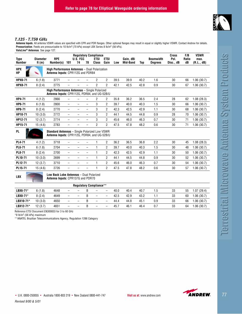
• U.K. 0800-250055 • Australia 1800-803 219 • New Zealand 0800-441-747 Visit us at: www.andrew.com 77
7.125 - 7.750 GHzAntenna Inputs. All antenna VSWR values are specified with CPR and PDR flanges. Other optional flanges may result in equal or slightly higher VSWR. Contact Andrew for details.Pressurization. Feeds are pressurizable to 10 lb/in2 (70 kPa) except LBX Series 8 lb/in2 (56 kPa).ValuLine® Antennas. See page 127.
Regulatory Compliance Cross F/B VSWRType Diameter RPE U.S. FCC ETSI ETSI Gain, dBi Beamwidth Pol. Ratio max.Number ft (m) Number(s) 101 74 78 Class Gain Low Mid-Band Top Degrees Disc., dB dB (R.L., dB)
HPX High Performance Antennas – Dual PolarizationHP Antenna Inputs: CPR112G and PDR84
HPX6-71 6 (1.8) 3771 – – – 2 2 39.5 39.9 40.2 1.6 30 66 1.06 (30.7)
HPX8-71 8 (2.4) 2775 – – – 2 2 42.1 42.5 42.8 0.9 30 67 1.06 (30.7)
High Performance Antennas – Single Polarized Antenna Inputs: CPR112G, PDR84, and UG-52B/U
HP4-71 4 (1.2) 2866 – – – 2 2 35.8 36.2 36.5 2.4 28 62 1.08 (28.3)
HP6-71 6 (1.8) 2800 – – – 3 2 39.7 40.0 40.3 1.5 30 66 1.06 (30.7)
HP8-71 8 (2.4) 2770 – – – 3 2 42.3 42.5 42.9 1.1 30 68 1.06 (30.7)
HP10-71 10 (3.0) 2772 – – – 3 2 44.1 44.5 44.8 0.9 28 70 1.06 (30.7)
HP12-71 12 (3.7) 2774 – – – 3 2 45.6 46.0 46.3 0.7 30 71 1.06 (30.7)
HP15-71 15 (4.6) 2783 – – – 2 2 47.5 47.8 48.2 0.6 30 71 1.06 (30.7)
PL Standard Antennas – Single Polarized Low VSWRAntenna Inputs: CPR112G, PDR84, and UG-52B/U
PL4-71 4 (1.2) 3718 – – – 1 2 36.2 36.5 36.8 2.2 30 45 1.08 (28.3)
PL6-71 6 (1.8) 2704 – – – 1 2 39.7 40.0 40.3 1.5 30 48 1.06 (30.7)
PL8-71 8 (2.4) 2700 – – – 1 2 42.3 42.5 42.9 1.1 30 50 1.06 (30.7)
PL10-71 10 (3.0) 2699 – – – 1 2 44.1 44.5 44.8 0.9 30 52 1.06 (30.7)
PL12-71 12 (3.7) 3710 – – – 1 2 45.6 46.0 46.3 0.7 30 54 1.06 (30.7)
PL15-71 15 (4.6) 2726 – – – 1 2 47.5 47.8 48.2 0.6 30 57 1.06 (30.7)
LBXLow Back Lobe Antennas – Dual PolarizedAntenna Inputs: CPR137G and PDR70
Regulatory Compliance**
LBX6-71* 6 (1.8) 4648 – – B – – 40.0 40.4 40.7 1.5 33 55 1.07 (29.4)
LBX8-71* 8 (2.4) 4649 – – B – – 42.5 42.9 43.2 1.1 33 60 1.06 (30.7)
LBX10-71* 10 (3.0) 4650 – – B – – 44.4 44.8 45.1 0.9 33 66 1.06 (30.7)
LBX12-71* 12 (3.7) 4651 – – B – – 45.7 46.1 46.4 0.7 33 64 1.06 (30.7)
Reference ETSI Document EN300833 for 3 to 60 GHz*8 lb/in2 (56 kPa) maximum**ANATEL Brazilian Telecommunications Agency, Regulation 1286 Category
Refer to page 78 for Elliptical Waveguide ordering information
Revised 9/00 & 5/01
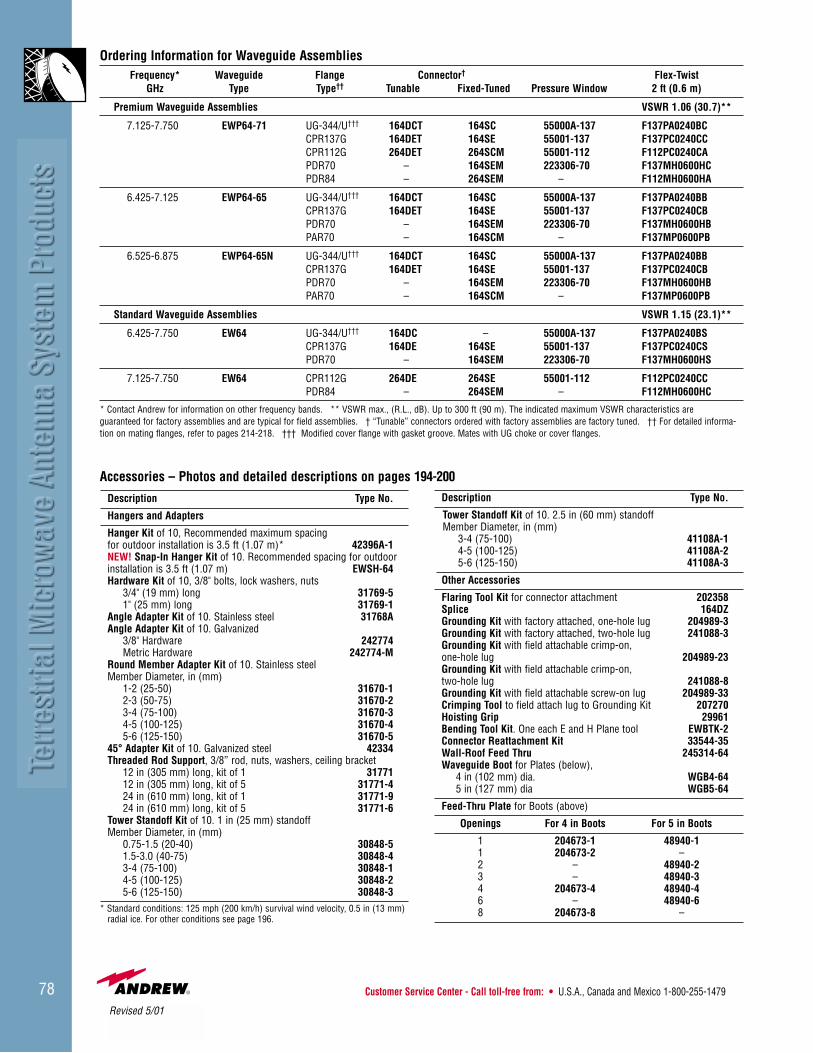
Customer Service Center - Call toll-free from: • U.S.A., Canada and Mexico 1-800-255-147978
Ordering Information for Waveguide AssembliesFrequency* Waveguide Flange Connector† Flex-Twist
GHz Type Type†† Tunable Fixed-Tuned Pressure Window 2 ft (0.6 m)
Premium Waveguide Assemblies VSWR 1.06 (30.7)**
7.125-7.750 EWP64-71 UG-344/U††† 164DCT 164SC 55000A-137 F137PA0240BCCPR137G 164DET 164SE 55001-137 F137PC0240CCCPR112G 264DET 264SCM 55001-112 F112PC0240CAPDR70 – 164SEM 223306-70 F137MH0600HCPDR84 – 264SEM – F112MH0600HA
6.425-7.125 EWP64-65 UG-344/U††† 164DCT 164SC 55000A-137 F137PA0240BBCPR137G 164DET 164SE 55001-137 F137PC0240CBPDR70 – 164SEM 223306-70 F137MH0600HBPAR70 – 164SCM – F137MP0600PB
6.525-6.875 EWP64-65N UG-344/U††† 164DCT 164SC 55000A-137 F137PA0240BBCPR137G 164DET 164SE 55001-137 F137PC0240CBPDR70 – 164SEM 223306-70 F137MH0600HBPAR70 – 164SCM – F137MP0600PB
Standard Waveguide Assemblies VSWR 1.15 (23.1)**
6.425-7.750 EW64 UG-344/U††† 164DC – 55000A-137 F137PA0240BSCPR137G 164DE 164SE 55001-137 F137PC0240CSPDR70 – 164SEM 223306-70 F137MH0600HS
7.125-7.750 EW64 CPR112G 264DE 264SE 55001-112 F112PC0240CCPDR84 – 264SEM – F112MH0600HC
* Contact Andrew for information on other frequency bands. ** VSWR max., (R.L., dB). Up to 300 ft (90 m). The indicated maximum VSWR characteristics are guaranteed for factory assemblies and are typical for field assemblies. † “Tunable” connectors ordered with factory assemblies are factory tuned. †† For detailed informa-tion on mating flanges, refer to pages 214-218. ††† Modified cover flange with gasket groove. Mates with UG choke or cover flanges.
Description Type No.
Hangers and Adapters
Hanger Kit of 10, Recommended maximum spacingfor outdoor installation is 3.5 ft (1.07 m)* 42396A-1NEW! Snap-In Hanger Kit of 10. Recommended spacing for outdoor installation is 3.5 ft (1.07 m) EWSH-64Hardware Kit of 10, 3/8" bolts, lock washers, nuts
3/4" (19 mm) long 31769-51" (25 mm) long 31769-1
Angle Adapter Kit of 10. Stainless steel 31768AAngle Adapter Kit of 10. Galvanized
3/8" Hardware 242774Metric Hardware 242774-M
Round Member Adapter Kit of 10. Stainless steelMember Diameter, in (mm)
1-2 (25-50) 31670-12-3 (50-75) 31670-23-4 (75-100) 31670-34-5 (100-125) 31670-45-6 (125-150) 31670-5
45° Adapter Kit of 10. Galvanized steel 42334Threaded Rod Support, 3/8” rod, nuts, washers, ceiling bracket
12 in (305 mm) long, kit of 1 3177112 in (305 mm) long, kit of 5 31771-424 in (610 mm) long, kit of 1 31771-924 in (610 mm) long, kit of 5 31771-6
Tower Standoff Kit of 10. 1 in (25 mm) standoffMember Diameter, in (mm)
0.75-1.5 (20-40) 30848-51.5-3.0 (40-75) 30848-43-4 (75-100) 30848-14-5 (100-125) 30848-25-6 (125-150) 30848-3
* Standard conditions: 125 mph (200 km/h) survival wind velocity, 0.5 in (13 mm) radial ice. For other conditions see page 196.
Description Type No.
Tower Standoff Kit of 10. 2.5 in (60 mm) standoffMember Diameter, in (mm)
3-4 (75-100) 41108A-14-5 (100-125) 41108A-25-6 (125-150) 41108A-3
Other Accessories
Flaring Tool Kit for connector attachment 202358Splice 164DZGrounding Kit with factory attached, one-hole lug 204989-3Grounding Kit with factory attached, two-hole lug 241088-3Grounding Kit with field attachable crimp-on, one-hole lug 204989-23Grounding Kit with field attachable crimp-on, two-hole lug 241088-8Grounding Kit with field attachable screw-on lug 204989-33Crimping Tool to field attach lug to Grounding Kit 207270Hoisting Grip 29961Bending Tool Kit. One each E and H Plane tool EWBTK-2Connector Reattachment Kit 33544-35Wall-Roof Feed Thru 245314-64Waveguide Boot for Plates (below),
4 in (102 mm) dia. WGB4-645 in (127 mm) dia WGB5-64
Feed-Thru Plate for Boots (above)
Openings For 4 in Boots For 5 in Boots
1 204673-1 48940-11 204673-2 –2 – 48940-23 – 48940-34 204673-4 48940-46 – 48940-68 204673-8 –
Accessories – Photos and detailed descriptions on pages 194-200
Revised 5/01
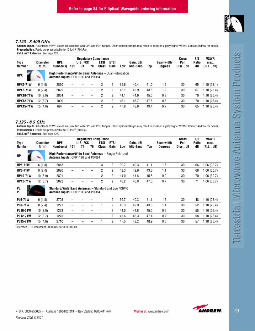
• U.K. 0800-250055 • Australia 1800-803 219 • New Zealand 0800-441-747 Visit us at: www.andrew.com 79
7.125 - 8.400 GHzAntenna Inputs. All antenna VSWR values are specified with CPR and PDR flanges. Other optional flanges may result in equal or slightly higher VSWR. Contact Andrew for details.Pressurization. Feeds are pressurizable to 10 lb/in2 (70 kPa).ValuLine® Antennas. See page 127.
Regulatory Compliance Cross F/B VSWRType Diameter RPE U.S. FCC ETSI ETSI Gain, dBi Beamwidth Pol. Ratio max.Number ft (m) Number(s) 101 74 78 Class Gain Low Mid-Band Top Degrees Disc., dB dB (R.L., dB)
HPXHigh Performance/Wide Band Antennas – Dual PolarizationAntenna Inputs: CPR112G and PDR84
HPX6-71W 6 (1.8) 2860 – – – 2 2 39.6 40.4 41.0 1.5 30 65 1.15 (23.1)
HPX8-71W 8 (2.4) 2825 – – – 2 2 42.1 42.9 43.5 1.2 30 67 1.10 (26.4)
HPX10-71W 10 (3.0) 2864 – – – 2 2 44.1 44.9 45.5 0.9 30 70 1.10 (26.4)
HPX12-71W 12 (3.7) 1009 – – – 2 2 46.1 46.7 47.5 0.8 30 70 1.10 (26.4)
HPX15-71W 15 (4.6) 697 – – – 2 2 47.9 48.6 49.4 0.7 30 65 1.10 (26.4)
7.125 - 8.5 GHzAntenna Inputs. All antenna VSWR values are specified with CPR and PDR flanges. Other optional flanges may result in equal or slightly higher VSWR. Contact Andrew for details.Pressurization. Feeds are pressurizable to 10 lb/in2 (70 kPa).ValuLine® Antennas. See page 127.
Regulatory Compliance Cross F/B VSWRType Diameter RPE U.S. FCC ETSI ETSI Gain, dBi Beamwidth Pol. Ratio max.Number ft (m) Number(s) 101 74 78 Class Gain Low Mid-Band Top Degrees Disc., dB dB (R.L., dB)
HPHigh Performance/Wide Band Antennas – Single PolarizedAntenna Inputs: CPR112G and PDR84
HP6-71W 6 (1.8) 2818 – – – 3 2 39.7 40.3 41.1 1.5 30 66 1.06 (30.7)
HP8-71W 8 (2.4) 2820 – – – 2 2 42.3 42.9 43.6 1.1 30 68 1.06 (30.7)
HP10-71W 10 (3.0) 2821 – – – 2 2 44.0 44.8 45.5 0.9 30 70 1.06 (30.7)
HP12-71W 12 (3.7) 2822 – – – 2 2 46.2 46.8 47.6 0.7 30 71 1.06 (30.7)
PL Standard/Wide Band Antennas – Standard and Low VSWRP Antenna Inputs: CPR112G and PDR84
PL6-71W 6 (1.8) 3703 – – – 1 2 39.7 40.3 41.1 1.5 30 48 1.10 (26.4)
PL8-71W 8 (2.4) 1271 – – – 1 2 42.3 42.9 43.6 1.1 30 52 1.10 (26.4)
PL10-71W 10 (3.0) 1273 – – – 1 2 44.0 44.8 45.5 0.9 30 55 1.10 (26.4)
PL12-71W 12 (3.7) 1275 – – – 1 2 45.6 46.3 47.1 0.7 30 58 1.10 (26.4)
PL15-71W 15 (4.6) 2710 – – – 1 2 47.5 48.2 48.9 0.6 30 57 1.10 (26.4)
Reference ETSI Document EN300833 for 3 to 60 GHz
Refer to page 84 for Elliptical Waveguide ordering information
Revised 7/00 & 5/01
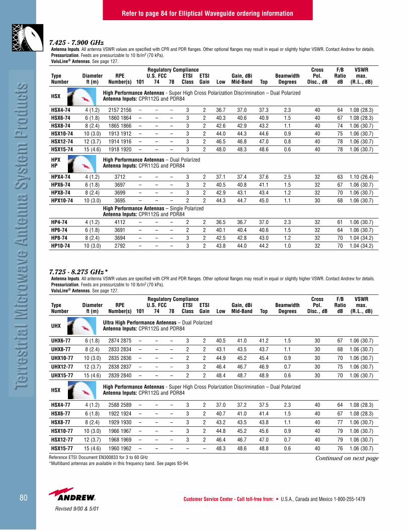
Customer Service Center - Call toll-free from: • U.S.A., Canada and Mexico 1-800-255-147980
7.425 - 7.900 GHzAntenna Inputs. All antenna VSWR values are specified with CPR and PDR flanges. Other optional flanges may result in equal or slightly higher VSWR. Contact Andrew for details.Pressurization. Feeds are pressurizable to 10 lb/in2 (70 kPa).ValuLine® Antennas. See page 127.
Regulatory Compliance Cross F/B VSWRType Diameter RPE U.S. FCC ETSI ETSI Gain, dBi Beamwidth Pol. Ratio max.Number ft (m) Number(s) 101 74 78 Class Gain Low Mid-Band Top Degrees Disc., dB dB (R.L., dB)
HSXHigh Performance Antennas - Super High Cross Polarization Discrimination – Dual PolarizedAntenna Inputs: CPR112G and PDR84
HSX4-74 4 (1.2) 2157 2156 – – – 3 2 36.7 37.0 37.3 2.3 40 64 1.08 (28.3)HSX6-74 6 (1.8) 1860 1864 – – – 3 2 40.3 40.6 40.9 1.5 40 67 1.08 (28.3)HSX8-74 8 (2.4) 1865 1866 – – – 3 2 42.6 42.9 43.2 1.1 40 74 1.06 (30.7)HSX10-74 10 (3.0) 1913 1912 – – – 3 2 44.0 44.3 44.6 0.9 40 75 1.06 (30.7)HSX12-74 12 (3.7) 1914 1916 – – – 3 2 46.5 46.8 47.0 0.8 40 78 1.06 (30.7)HSX15-74 15 (4.6) 1918 1920 – – – 3 2 48.0 48.3 48.6 0.6 40 78 1.06 (30.7)
HPX High Performance Antennas – Dual PolarizedHP Antenna Inputs: CPR112G and PDR84
HPX4-74 4 (1.2) 3712 – – – 3 2 37.1 37.4 37.6 2.5 32 63 1.10 (26.4)HPX6-74 6 (1.8) 3697 – – – 3 2 40.5 40.8 41.1 1.5 32 67 1.06 (30.7)HPX8-74 8 (2.4) 3699 – – – 3 2 42.9 43.1 43.4 1.2 32 70 1.06 (30.7)HPX10-74 10 (3.0) 3695 – – – 2 2 44.3 44.7 45.0 1.1 30 68 1.06 (30.7)
High Performance Antennas – Single PolarizedAntenna Inputs: CPR112G and PDR84
HP4-74 4 (1.2) 4112 – – – 2 2 36.5 36.7 37.0 2.3 32 61 1.06 (30.7)HP6-74 6 (1.8) 3691 – – – 2 2 40.1 40.4 40.6 1.5 32 64 1.06 (30.7)HP8-74 8 (2.4) 3694 – – – 3 2 42.5 42.8 43.0 1.2 32 70 1.04 (34.2)HP10-74 10 (3.0) 2792 – – – 3 2 43.8 44.0 44.2 1.0 32 70 1.04 (34.2)
7.725 - 8.275 GHz*Antenna Inputs. All antenna VSWR values are specified with CPR and PDR flanges. Other optional flanges may result in equal or slightly higher VSWR. Contact Andrew for details.Pressurization. Feeds are pressurizable to 10 lb/in2 (70 kPa).ValuLine® Antennas. See page 127.
Regulatory Compliance Cross F/B VSWRType Diameter RPE U.S. FCC ETSI ETSI Gain, dBi Beamwidth Pol. Ratio max.Number ft (m) Number(s) 101 74 78 Class Gain Low Mid-Band Top Degrees Disc., dB dB (R.L., dB)
UHXUltra High Performance Antennas – Dual PolarizedAntenna Inputs: CPR112G and PDR84
UHX6-77 6 (1.8) 2874 2875 – – – 3 2 40.5 41.0 41.2 1.5 30 67 1.06 (30.7)
UHX8-77 8 (2.4) 2833 2834 – – – 2 2 43.1 43.5 43.7 1.1 30 68 1.06 (30.7)
UHX10-77 10 (3.0) 2835 2836 – – – 2 2 44.9 45.2 45.4 0.9 30 70 1.06 (30.7)
UHX12-77 12 (3.7) 2838 2837 – – – 3 2 46.4 46.7 46.9 0.7 30 75 1.06 (30.7)
UHX15-77 15 (4.6) 2839 2840 – – – 2 2 48.4 48.7 48.9 0.6 30 70 1.06 (30.7)
HSXHigh Performance Antennas - Super High Cross Polarization Discrimination – Dual PolarizedAntenna Inputs: CPR112G and PDR84
HSX4-77 4 (1.2) 2588 2589 – – – 3 2 37.0 37.2 37.5 2.3 40 64 1.08 (28.3)
HSX6-77 6 (1.8) 1922 1924 – – – 3 2 40.7 41.0 41.4 1.5 40 67 1.08 (28.3)
HSX8-77 8 (2.4) 1929 1930 – – – 3 2 43.2 43.5 43.8 1.1 40 77 1.06 (30.7)
HSX10-77 10 (3.0) 1966 1967 – – – 3 2 44.8 45.2 45.6 0.9 40 79 1.06 (30.7)
HSX12-77 12 (3.7) 1968 1969 – – – 3 2 46.4 46.7 47.0 0.7 40 79 1.06 (30.7)
HSX15-77 15 (4.6) 1960 1962 – – – – – 48.3 48.6 48.8 0.6 40 76 1.06 (30.7)
Reference ETSI Document EN300833 for 3 to 60 GHz*Multiband antennas are available in this frequency band. See pages 93-94.
Continued on next page
Refer to page 84 for Elliptical Waveguide ordering information
Revised 9/00 & 5/01
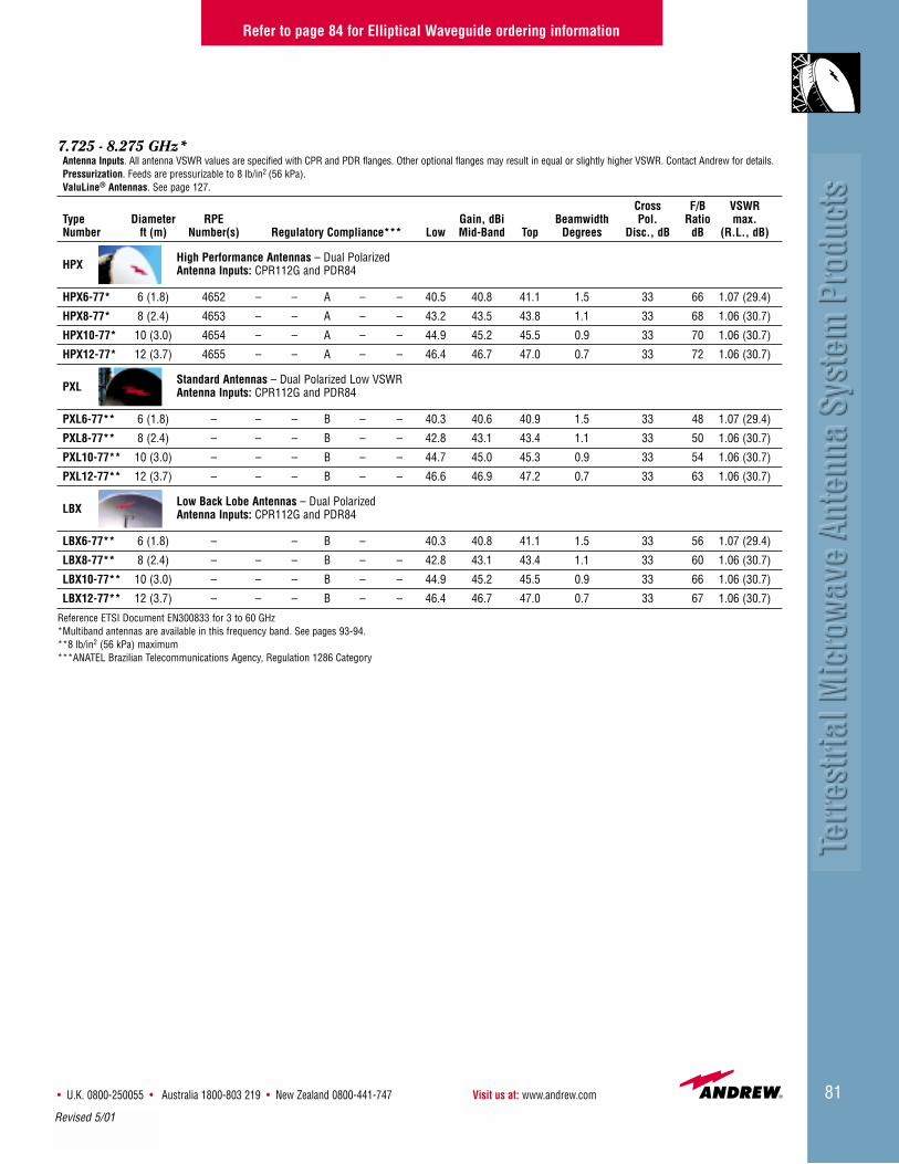
• U.K. 0800-250055 • Australia 1800-803 219 • New Zealand 0800-441-747 Visit us at: www.andrew.com 81
Refer to page 84 for Elliptical Waveguide ordering information
7.725 - 8.275 GHz*Antenna Inputs. All antenna VSWR values are specified with CPR and PDR flanges. Other optional flanges may result in equal or slightly higher VSWR. Contact Andrew for details.Pressurization. Feeds are pressurizable to 8 lb/in2 (56 kPa).ValuLine® Antennas. See page 127.
Cross F/B VSWRType Diameter RPE Gain, dBi Beamwidth Pol. Ratio max.Number ft (m) Number(s) Regulatory Compliance*** Low Mid-Band Top Degrees Disc., dB dB (R.L., dB)
HPXHigh Performance Antennas – Dual PolarizedAntenna Inputs: CPR112G and PDR84
HPX6-77* 6 (1.8) 4652 – – A – – 40.5 40.8 41.1 1.5 33 66 1.07 (29.4)
HPX8-77* 8 (2.4) 4653 – – A – – 43.2 43.5 43.8 1.1 33 68 1.06 (30.7)
HPX10-77* 10 (3.0) 4654 – – A – – 44.9 45.2 45.5 0.9 33 70 1.06 (30.7)
HPX12-77* 12 (3.7) 4655 – – A – – 46.4 46.7 47.0 0.7 33 72 1.06 (30.7)
PXLStandard Antennas – Dual Polarized Low VSWRAntenna Inputs: CPR112G and PDR84
PXL6-77** 6 (1.8) – – – B – – 40.3 40.6 40.9 1.5 33 48 1.07 (29.4)
PXL8-77** 8 (2.4) – – – B – – 42.8 43.1 43.4 1.1 33 50 1.06 (30.7)
PXL10-77** 10 (3.0) – – – B – – 44.7 45.0 45.3 0.9 33 54 1.06 (30.7)
PXL12-77** 12 (3.7) – – – B – – 46.6 46.9 47.2 0.7 33 63 1.06 (30.7)
LBXLow Back Lobe Antennas – Dual PolarizedAntenna Inputs: CPR112G and PDR84
LBX6-77** 6 (1.8) – – B – 40.3 40.8 41.1 1.5 33 56 1.07 (29.4)
LBX8-77** 8 (2.4) – – – B – – 42.8 43.1 43.4 1.1 33 60 1.06 (30.7)
LBX10-77** 10 (3.0) – – – B – – 44.9 45.2 45.5 0.9 33 66 1.06 (30.7)
LBX12-77** 12 (3.7) – – – B – – 46.4 46.7 47.0 0.7 33 67 1.06 (30.7)
Reference ETSI Document EN300833 for 3 to 60 GHz*Multiband antennas are available in this frequency band. See pages 93-94.**8 lb/in2 (56 kPa) maximum***ANATEL Brazilian Telecommunications Agency, Regulation 1286 Category
Revised 5/01
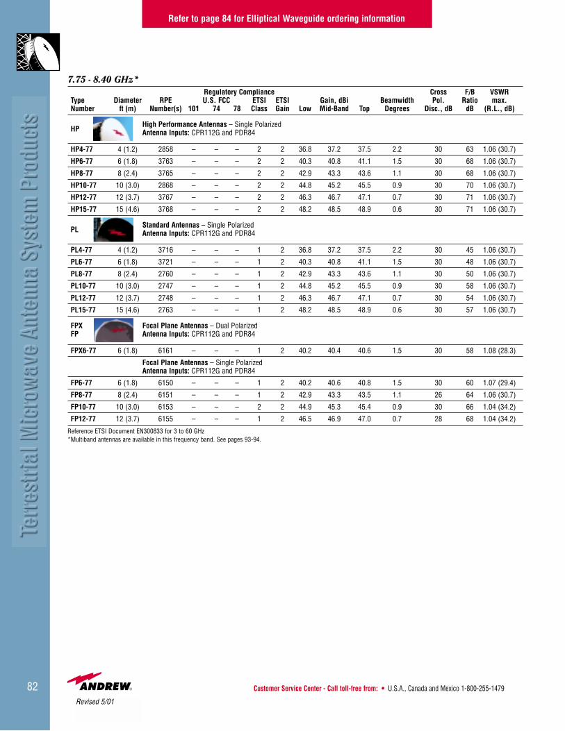
Customer Service Center - Call toll-free from: • U.S.A., Canada and Mexico 1-800-255-147982
Refer to page 84 for Elliptical Waveguide ordering information
7.75 - 8.40 GHz*Regulatory Compliance Cross F/B VSWR
Type Diameter RPE U.S. FCC ETSI ETSI Gain, dBi Beamwidth Pol. Ratio max.Number ft (m) Number(s) 101 74 78 Class Gain Low Mid-Band Top Degrees Disc., dB dB (R.L., dB)
HPHigh Performance Antennas – Single PolarizedAntenna Inputs: CPR112G and PDR84
HP4-77 4 (1.2) 2858 – – – 2 2 36.8 37.2 37.5 2.2 30 63 1.06 (30.7)
HP6-77 6 (1.8) 3763 – – – 2 2 40.3 40.8 41.1 1.5 30 68 1.06 (30.7)
HP8-77 8 (2.4) 3765 – – – 2 2 42.9 43.3 43.6 1.1 30 68 1.06 (30.7)
HP10-77 10 (3.0) 2868 – – – 2 2 44.8 45.2 45.5 0.9 30 70 1.06 (30.7)
HP12-77 12 (3.7) 3767 – – – 2 2 46.3 46.7 47.1 0.7 30 71 1.06 (30.7)
HP15-77 15 (4.6) 3768 – – – 2 2 48.2 48.5 48.9 0.6 30 71 1.06 (30.7)
PLStandard Antennas – Single PolarizedAntenna Inputs: CPR112G and PDR84
PL4-77 4 (1.2) 3716 – – – 1 2 36.8 37.2 37.5 2.2 30 45 1.06 (30.7)
PL6-77 6 (1.8) 3721 – – – 1 2 40.3 40.8 41.1 1.5 30 48 1.06 (30.7)
PL8-77 8 (2.4) 2760 – – – 1 2 42.9 43.3 43.6 1.1 30 50 1.06 (30.7)
PL10-77 10 (3.0) 2747 – – – 1 2 44.8 45.2 45.5 0.9 30 58 1.06 (30.7)
PL12-77 12 (3.7) 2748 – – – 1 2 46.3 46.7 47.1 0.7 30 54 1.06 (30.7)
PL15-77 15 (4.6) 2763 – – – 1 2 48.2 48.5 48.9 0.6 30 57 1.06 (30.7)
FPX Focal Plane Antennas – Dual PolarizedFP Antenna Inputs: CPR112G and PDR84
FPX6-77 6 (1.8) 6161 – – – 1 2 40.2 40.4 40.6 1.5 30 58 1.08 (28.3)
Focal Plane Antennas – Single PolarizedAntenna Inputs: CPR112G and PDR84
FP6-77 6 (1.8) 6150 – – – 1 2 40.2 40.6 40.8 1.5 30 60 1.07 (29.4)
FP8-77 8 (2.4) 6151 – – – 1 2 42.9 43.3 43.5 1.1 26 64 1.06 (30.7)
FP10-77 10 (3.0) 6153 – – – 2 2 44.9 45.3 45.4 0.9 30 66 1.04 (34.2)
FP12-77 12 (3.7) 6155 – – – 1 2 46.5 46.9 47.0 0.7 28 68 1.04 (34.2)
Reference ETSI Document EN300833 for 3 to 60 GHz*Multiband antennas are available in this frequency band. See pages 93-94.
Revised 5/01
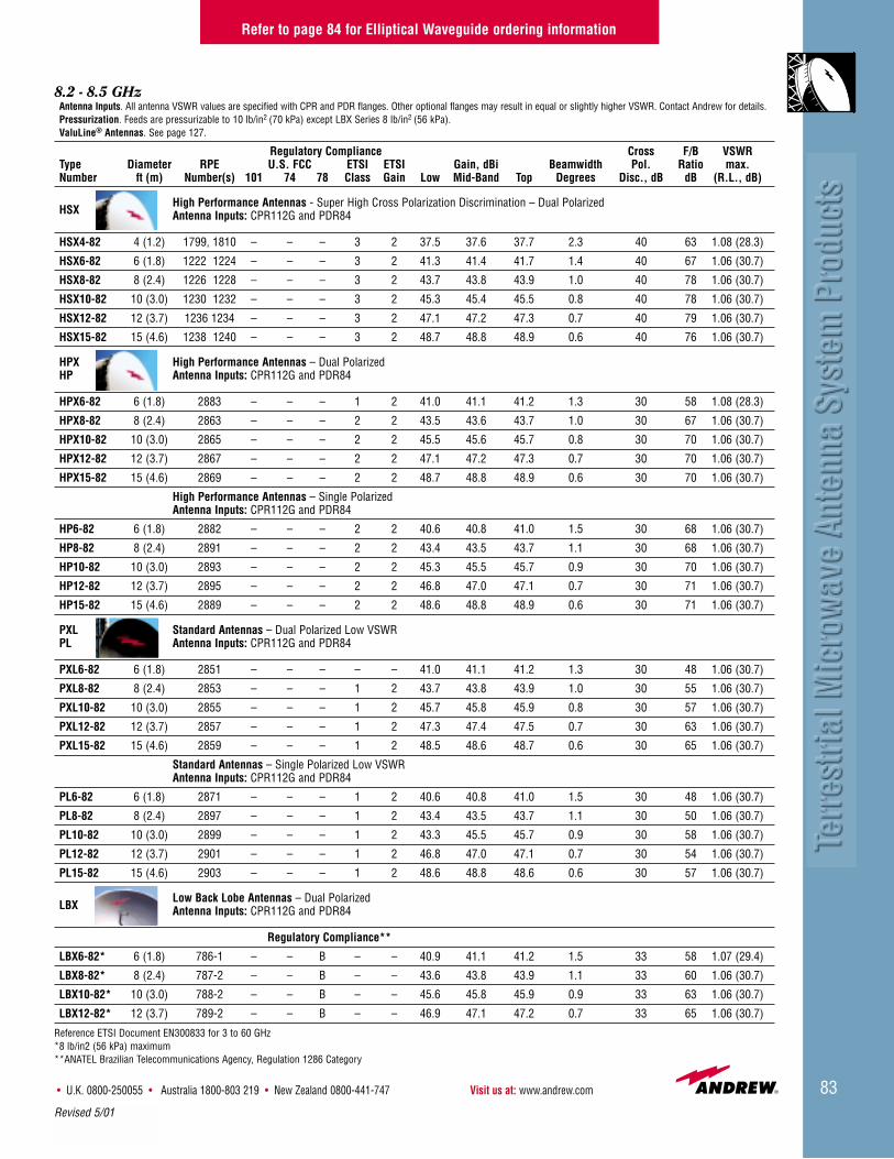
• U.K. 0800-250055 • Australia 1800-803 219 • New Zealand 0800-441-747 Visit us at: www.andrew.com 83
8.2 - 8.5 GHzAntenna Inputs. All antenna VSWR values are specified with CPR and PDR flanges. Other optional flanges may result in equal or slightly higher VSWR. Contact Andrew for details.Pressurization. Feeds are pressurizable to 10 lb/in2 (70 kPa) except LBX Series 8 lb/in2 (56 kPa).ValuLine® Antennas. See page 127.
Regulatory Compliance Cross F/B VSWRType Diameter RPE U.S. FCC ETSI ETSI Gain, dBi Beamwidth Pol. Ratio max.Number ft (m) Number(s) 101 74 78 Class Gain Low Mid-Band Top Degrees Disc., dB dB (R.L., dB)
HSXHigh Performance Antennas - Super High Cross Polarization Discrimination – Dual PolarizedAntenna Inputs: CPR112G and PDR84
HSX4-82 4 (1.2) 1799, 1810 – – – 3 2 37.5 37.6 37.7 2.3 40 63 1.08 (28.3)
HSX6-82 6 (1.8) 1222 1224 – – – 3 2 41.3 41.4 41.7 1.4 40 67 1.06 (30.7)
HSX8-82 8 (2.4) 1226 1228 – – – 3 2 43.7 43.8 43.9 1.0 40 78 1.06 (30.7)
HSX10-82 10 (3.0) 1230 1232 – – – 3 2 45.3 45.4 45.5 0.8 40 78 1.06 (30.7)
HSX12-82 12 (3.7) 1236 1234 – – – 3 2 47.1 47.2 47.3 0.7 40 79 1.06 (30.7)
HSX15-82 15 (4.6) 1238 1240 – – – 3 2 48.7 48.8 48.9 0.6 40 76 1.06 (30.7)
HPX High Performance Antennas – Dual PolarizedHP Antenna Inputs: CPR112G and PDR84
HPX6-82 6 (1.8) 2883 – – – 1 2 41.0 41.1 41.2 1.3 30 58 1.08 (28.3)
HPX8-82 8 (2.4) 2863 – – – 2 2 43.5 43.6 43.7 1.0 30 67 1.06 (30.7)
HPX10-82 10 (3.0) 2865 – – – 2 2 45.5 45.6 45.7 0.8 30 70 1.06 (30.7)
HPX12-82 12 (3.7) 2867 – – – 2 2 47.1 47.2 47.3 0.7 30 70 1.06 (30.7)
HPX15-82 15 (4.6) 2869 – – – 2 2 48.7 48.8 48.9 0.6 30 70 1.06 (30.7)
High Performance Antennas – Single PolarizedAntenna Inputs: CPR112G and PDR84
HP6-82 6 (1.8) 2882 – – – 2 2 40.6 40.8 41.0 1.5 30 68 1.06 (30.7)
HP8-82 8 (2.4) 2891 – – – 2 2 43.4 43.5 43.7 1.1 30 68 1.06 (30.7)
HP10-82 10 (3.0) 2893 – – – 2 2 45.3 45.5 45.7 0.9 30 70 1.06 (30.7)
HP12-82 12 (3.7) 2895 – – – 2 2 46.8 47.0 47.1 0.7 30 71 1.06 (30.7)
HP15-82 15 (4.6) 2889 – – – 2 2 48.6 48.8 48.9 0.6 30 71 1.06 (30.7)
PXL Standard Antennas – Dual Polarized Low VSWRPL Antenna Inputs: CPR112G and PDR84
PXL6-82 6 (1.8) 2851 – – – – – 41.0 41.1 41.2 1.3 30 48 1.06 (30.7)
PXL8-82 8 (2.4) 2853 – – – 1 2 43.7 43.8 43.9 1.0 30 55 1.06 (30.7)
PXL10-82 10 (3.0) 2855 – – – 1 2 45.7 45.8 45.9 0.8 30 57 1.06 (30.7)
PXL12-82 12 (3.7) 2857 – – – 1 2 47.3 47.4 47.5 0.7 30 63 1.06 (30.7)
PXL15-82 15 (4.6) 2859 – – – 1 2 48.5 48.6 48.7 0.6 30 65 1.06 (30.7)
Standard Antennas – Single Polarized Low VSWRAntenna Inputs: CPR112G and PDR84
PL6-82 6 (1.8) 2871 – – – 1 2 40.6 40.8 41.0 1.5 30 48 1.06 (30.7)
PL8-82 8 (2.4) 2897 – – – 1 2 43.4 43.5 43.7 1.1 30 50 1.06 (30.7)
PL10-82 10 (3.0) 2899 – – – 1 2 43.3 45.5 45.7 0.9 30 58 1.06 (30.7)
PL12-82 12 (3.7) 2901 – – – 1 2 46.8 47.0 47.1 0.7 30 54 1.06 (30.7)
PL15-82 15 (4.6) 2903 – – – 1 2 48.6 48.8 48.6 0.6 30 57 1.06 (30.7)
LBXLow Back Lobe Antennas – Dual PolarizedAntenna Inputs: CPR112G and PDR84
Regulatory Compliance**
LBX6-82* 6 (1.8) 786-1 – – B – – 40.9 41.1 41.2 1.5 33 58 1.07 (29.4)
LBX8-82* 8 (2.4) 787-2 – – B – – 43.6 43.8 43.9 1.1 33 60 1.06 (30.7)
LBX10-82* 10 (3.0) 788-2 – – B – – 45.6 45.8 45.9 0.9 33 63 1.06 (30.7)
LBX12-82* 12 (3.7) 789-2 – – B – – 46.9 47.1 47.2 0.7 33 65 1.06 (30.7)
Reference ETSI Document EN300833 for 3 to 60 GHz*8 lb/in2 (56 kPa) maximum**ANATEL Brazilian Telecommunications Agency, Regulation 1286 Category
Refer to page 84 for Elliptical Waveguide ordering information
Revised 5/01
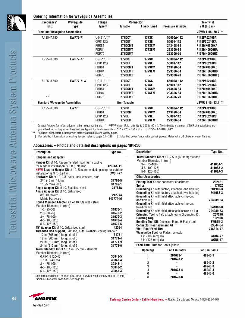
Customer Service Center - Call toll-free from: • U.S.A., Canada and Mexico 1-800-255-147984
Ordering Information for Waveguide AssembliesFrequency* Waveguide Flange Connector† Flex-Twist
GHz Type Type†† Tunable Fixed-Tuned Pressure Window 2 ft (0.6 m)
Premium Waveguide Assemblies VSWR 1.06 (30.7)**
7.125–7.750 EWP77-71 UG-51/U††† 177DCT 177SC 55000A-112 F112PA0240BACPR112G 177DET 177SE 55001-112 F112PC0240CAPBR84 177DCMT 177SCM 243498-84 F112MK0600KAPDR84 177DEMT 177SEM 223306-84 F112MH0600HAPDR70 277DEMT – 223306-70 F137MH0600HC
7.725–8.500 EWP77-77 UG-51/U††† 177DCT 177SC 55000A-112 F112PA0240BBCPR112G 177DET 177SE 55001-112 F112PC0240CBPBR84 177DCMT 177SCM 243498-84 F112MK0600KBPDR84 177DEMT 177SEM 223306-84 F112MH0600HBPDR70 277DEMT – 223306-70 F137MH0600HF‡
7.125–8.500 EWP77-71W UG-51/U††† 177DCT 177SC 55000A-112 F112PA0240BCCPR112G 177DET 177SE 55001-112 F112PC0240CCPBR84 177DCMT 177SCM 243498-84 F112MK0600KCPDR84 177DEMT 177SEM 223306-84 F112MH0600HC
*** PDR70 277DEMT – 223306-70 F137MH0600HE
Standard Waveguide Assemblies Non-Tunable VSWR 1.15 (23.1)**
7.125–8.500 EW77 UG-51/U††† 177DC 177SC 55000A-112 F112PA0240BCPBR84 177DCM 177SCM 243498-84 F112MK0600KCCPR112G 177DE 177SE 55001-112 F112PC0240CCPDR84 177DEM 177SEM 223306-84 F112MH0600HC
* Contact Andrew for information on other frequency bands. ** VSWR max., (R.L., dB). Up to 300 ft (90 m). The indicated maximum VSWR characteristics are guaranteed for factory assemblies and are typical for field assemblies. *** 7.425 - 7.925 GHz ‡ 7.725 - 8.3 GHz ONLY
† “Tunable” connectors ordered with factory assemblies are factory tuned. †† For detailed information on mating flanges, refer to pages 214-218. ††† Modified cover flange with gasket groove. Mates with UG choke or cover flanges.
Description Type No.
Hangers and Adapters
Hanger Kit of 10, Recommended maximum spacingfor outdoor installation is 3 ft (0.91 m)* 42396A-11NEW! Snap-In Hanger Kit of 10. Recommended spacing for outdoor installation is 3 ft (0.91 m) EWSH-77Hardware Kit of 10, 3/8" bolts, lock washers, nuts
3/4" (19 mm) long 31769-51" (25 mm) long 31769-1
Angle Adapter Kit of 10. Stainless steel 31768AAngle Adapter Kit of 10. Galvanized
3/8" Hardware 242774Metric Hardware 242774-M
Round Member Adapter Kit of 10. Stainless steelMember Diameter, in (mm)
1-2 (25-50) 31670-12-3 (50-75) 31670-23-4 (75-100) 31670-34-5 (100-125) 31670-45-6 (125-150) 31670-5
45° Adapter Kit of 10. Galvanized steel 42334Threaded Rod Support, 3/8” rod, nuts, washers, ceiling bracket
12 in (305 mm) long, kit of 1 3177112 in (305 mm) long, kit of 5 31771-424 in (610 mm) long, kit of 1 31771-924 in (610 mm) long, kit of 5 31771-6
Tower Standoff Kit of 10. 1 in (25 mm) standoffMember Diameter, in (mm)
0.75-1.5 (20-40) 30848-51.5-3.0 (40-75) 30848-43-4 (75-100) 30848-14-5 (100-125) 30848-25-6 (125-150) 30848-3
* Standard conditions: 125 mph (200 km/h) survival wind velocity, 0.5 in (13 mm) radial ice. For other conditions see page 196.
Description Type No.
Tower Standoff Kit of 10. 2.5 in (60 mm) standoffMember Diameter, in (mm)
3-4 (75-100) 41108A-14-5 (100-125) 41108A-25-6 (125-150) 41108A-3
Other Accessories
Flaring Tool Kit for connector attachment 202421Splice 177DZGrounding Kit with factory attached, one-hole lug 204989-3Grounding Kit with factory attached, two-hole lug 241088-3Grounding Kit with field attachable crimp-on, one-hole lug 204989-23Grounding Kit with field attachable crimp-on, two-hole lug 241088-8Grounding Kit with field attachable screw-on lug 204989-33Crimping Tool to field attach lug to Grounding Kit 207270Hoisting Grip 19256BBending Tool Kit. One each E and H Plane tool EWBTK-2Connector Reattachment Kit 33544-34Wall-Roof Feed Thru 245314-77Waveguide Boot for Plates (below),
4 in (102 mm) dia. WGB4-775 in (127 mm) dia WGB5-77
Feed-Thru Plate for Boots (above)
Openings For 4 in Boots For 5 in Boots
1 204673-1 48940-11 204673-2 –2 – 48940-23 – 48940-34 204673-4 48940-46 – 48940-68 204673-8 –
Accessories – Photos and detailed descriptions on pages 194-200
Revised 5/01
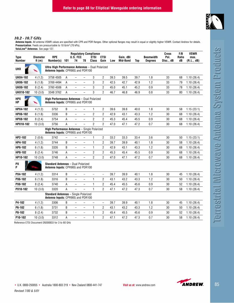
• U.K. 0800-250055 • Australia 1800-803 219 • New Zealand 0800-441-747 Visit us at: www.andrew.com 85
10.2 - 10.7 GHzAntenna Inputs. All antenna VSWR values are specified with CPR and PDR flanges. Other optional flanges may result in equal or slightly higher VSWR. Contact Andrew for details.Pressurization. Feeds are pressurizable to 10 lb/in2 (70 kPa).ValuLine® Antennas. See page 127.
Regulatory Compliance Cross F/B VSWRType Diameter RPE U.S. FCC ETSI ETSI Gain, dBi Beamwidth Pol. Ratio max.Number ft (m) Number(s) 101 74 78 Class Gain Low Mid-Band Top Degrees Disc., dB dB (R.L., dB)
UHXUltra High Performance Antennas – Dual PolarizedAntenna Inputs: CPR90G and PDR100
UHX4-102 4 (1.2) 3758 4505 A – – 3 2 39.3 39.5 39.7 1.8 33 68 1.10 (26.4)
UHX6-102 6 (1.8) 3769 4494 A – – 3 2 42.5 42.7 42.9 1.2 33 79 1.10 (26.4)
UHX8-102 8 (2.4) 3760 4506 A – – 3 2 45.0 45.1 45.2 0.9 33 78 1.10 (26.4)
UHX10-102 10 (3.0) 3348 3762 A – – 3 2 46.7 46.8 46.9 0.8 33 80 1.10 (26.4)
HPX High Performance Antennas – Dual PolarizedHP Antenna Inputs: CPR90G and PDR100
HPX4-102 4 (1.2) 3752 B – – 1 2 39.6 39.8 40.0 1.8 30 58 1.15 (23.1)
HPX6-102 6 (1.8) 3336 B – – 2 2 42.9 43.1 43.3 1.2 30 68 1.10 (26.4)
HPX8-102 8 (2.4) 3754 A – – 2 2 45.3 45.4 45.5 0.9 30 68 1.10 (26.4)
HPX10-102 10 (3.0) 3756 A – – 2 2 47.0 47.1 47.2 0.7 30 68 1.10 (26.4)
High Performance Antennas – Single PolarizedAntenna Inputs: CPR90G and PDR100
HP2-102 2 (0.6) 3742 – – – 1 2 33.2 33.3 33.4 3.6 30 50 1.15 (23.1)
HP4-102 4 (1.2) 3744 B – – 1 2 39.7 39.9 40.1 1.8 30 58 1.10 (26.4)
HP6-102 6 (1.8) 3326 B – – 1 2 42.9 43.1 43.3 1.2 30 68 1.10 (26.4)
HP8-102 8 (2.4) 3746 A – – 2 2 45.3 45.4 45.5 0.9 30 68 1.10 (26.4)
HP10-102 10 (3.0) 3748 A – – 2 2 47.0 47.1 47.2 0.7 30 68 1.10 (26.4)
PX Standard Antennas – Dual PolarizedP Antenna Inputs: CPR90G and PDR100
PX4-102 4 (1.2) 3314 B – – – – 39.7 39.9 40.1 1.8 30 45 1.10 (26.4)
PX6-102 6 (1.8) 3316 B – – 1 2 43.1 43.2 43.3 1.2 30 50 1.10 (26.4)
PX8-102 8 (2.4) 3740 A – – 1 2 45.4 45.5 45.6 0.9 30 52 1.10 (26.4)
PX10-102 10 (3.0) 3320 A – – 1 2 47.1 47.2 47.3 0.7 30 58 1.10 (26.4)
Standard Antennas – Single PolarizedAntenna Inputs: CPR90G and PDR100
P4-102 4 (1.2) 3306 B – – – – 39.7 39.9 40.1 1.8 30 45 1.10 (26.4)
P6-102 6 (1.8) 3731 B – – 1 2 43.1 43.2 43.3 1.2 30 50 1.10 (26.4)
P8-102 8 (2.4) 3732 B – – 1 2 45.4 45.5 45.6 0.9 30 52 1.10 (26.4)
P10-102 10 (3.0) 3312 A – – 1 2 47.1 47.2 47.3 0.7 30 58 1.10 (26.4)
Reference ETSI Document EN300833 for 3 to 60 GHz
Refer to page 88 for Elliptical Waveguide ordering information
Revised 7/00 & 5/01
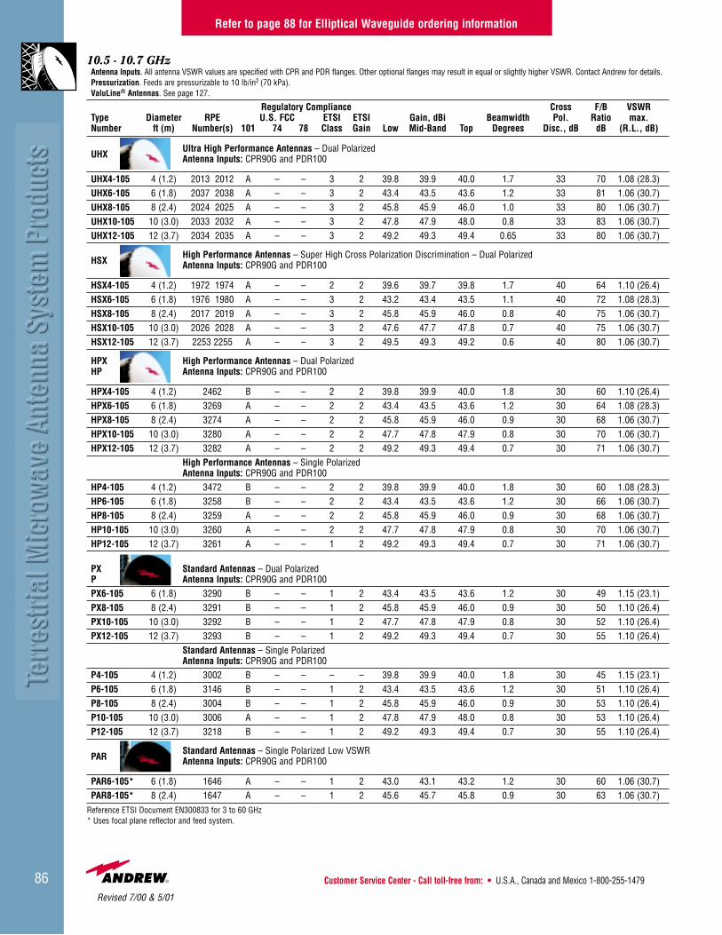
Customer Service Center - Call toll-free from: • U.S.A., Canada and Mexico 1-800-255-147986
10.5 - 10.7 GHzAntenna Inputs. All antenna VSWR values are specified with CPR and PDR flanges. Other optional flanges may result in equal or slightly higher VSWR. Contact Andrew for details.Pressurization. Feeds are pressurizable to 10 lb/in2 (70 kPa).ValuLine® Antennas. See page 127.
Regulatory Compliance Cross F/B VSWRType Diameter RPE U.S. FCC ETSI ETSI Gain, dBi Beamwidth Pol. Ratio max.Number ft (m) Number(s) 101 74 78 Class Gain Low Mid-Band Top Degrees Disc., dB dB (R.L., dB)
UHXUltra High Performance Antennas – Dual PolarizedAntenna Inputs: CPR90G and PDR100
UHX4-105 4 (1.2) 2013 2012 A – – 3 2 39.8 39.9 40.0 1.7 33 70 1.08 (28.3)UHX6-105 6 (1.8) 2037 2038 A – – 3 2 43.4 43.5 43.6 1.2 33 81 1.06 (30.7)UHX8-105 8 (2.4) 2024 2025 A – – 3 2 45.8 45.9 46.0 1.0 33 80 1.06 (30.7)UHX10-105 10 (3.0) 2033 2032 A – – 3 2 47.8 47.9 48.0 0.8 33 83 1.06 (30.7)UHX12-105 12 (3.7) 2034 2035 A – – 3 2 49.2 49.3 49.4 0.65 33 80 1.06 (30.7)
HSXHigh Performance Antennas – Super High Cross Polarization Discrimination – Dual PolarizedAntenna Inputs: CPR90G and PDR100
HSX4-105 4 (1.2) 1972 1974 A – – 2 2 39.6 39.7 39.8 1.7 40 64 1.10 (26.4)HSX6-105 6 (1.8) 1976 1980 A – – 3 2 43.2 43.4 43.5 1.1 40 72 1.08 (28.3)HSX8-105 8 (2.4) 2017 2019 A – – 3 2 45.8 45.9 46.0 0.8 40 75 1.06 (30.7)HSX10-105 10 (3.0) 2026 2028 A – – 3 2 47.6 47.7 47.8 0.7 40 75 1.06 (30.7)HSX12-105 12 (3.7) 2253 2255 A – – 3 2 49.5 49.3 49.2 0.6 40 80 1.06 (30.7)
HPX High Performance Antennas – Dual PolarizedHP Antenna Inputs: CPR90G and PDR100
HPX4-105 4 (1.2) 2462 B – – 2 2 39.8 39.9 40.0 1.8 30 60 1.10 (26.4)HPX6-105 6 (1.8) 3269 A – – 2 2 43.4 43.5 43.6 1.2 30 64 1.08 (28.3)HPX8-105 8 (2.4) 3274 A – – 2 2 45.8 45.9 46.0 0.9 30 68 1.06 (30.7)HPX10-105 10 (3.0) 3280 A – – 2 2 47.7 47.8 47.9 0.8 30 70 1.06 (30.7)HPX12-105 12 (3.7) 3282 A – – 2 2 49.2 49.3 49.4 0.7 30 71 1.06 (30.7)
High Performance Antennas – Single PolarizedAntenna Inputs: CPR90G and PDR100
HP4-105 4 (1.2) 3472 B – – 2 2 39.8 39.9 40.0 1.8 30 60 1.08 (28.3)HP6-105 6 (1.8) 3258 B – – 2 2 43.4 43.5 43.6 1.2 30 66 1.06 (30.7)HP8-105 8 (2.4) 3259 A – – 2 2 45.8 45.9 46.0 0.9 30 68 1.06 (30.7)HP10-105 10 (3.0) 3260 A – – 2 2 47.7 47.8 47.9 0.8 30 70 1.06 (30.7)HP12-105 12 (3.7) 3261 A – – 1 2 49.2 49.3 49.4 0.7 30 71 1.06 (30.7)
PX Standard Antennas – Dual PolarizedP Antenna Inputs: CPR90G and PDR100PX6-105 6 (1.8) 3290 B – – 1 2 43.4 43.5 43.6 1.2 30 49 1.15 (23.1)PX8-105 8 (2.4) 3291 B – – 1 2 45.8 45.9 46.0 0.9 30 50 1.10 (26.4)PX10-105 10 (3.0) 3292 B – – 1 2 47.7 47.8 47.9 0.8 30 52 1.10 (26.4)PX12-105 12 (3.7) 3293 B – – 1 2 49.2 49.3 49.4 0.7 30 55 1.10 (26.4)
Standard Antennas – Single PolarizedAntenna Inputs: CPR90G and PDR100
P4-105 4 (1.2) 3002 B – – – – 39.8 39.9 40.0 1.8 30 45 1.15 (23.1)P6-105 6 (1.8) 3146 B – – 1 2 43.4 43.5 43.6 1.2 30 51 1.10 (26.4)P8-105 8 (2.4) 3004 B – – 1 2 45.8 45.9 46.0 0.9 30 53 1.10 (26.4)P10-105 10 (3.0) 3006 A – – 1 2 47.8 47.9 48.0 0.8 30 53 1.10 (26.4)P12-105 12 (3.7) 3218 B – – 1 2 49.2 49.3 49.4 0.7 30 55 1.10 (26.4)
PARStandard Antennas – Single Polarized Low VSWRAntenna Inputs: CPR90G and PDR100
PAR6-105* 6 (1.8) 1646 A – – 1 2 43.0 43.1 43.2 1.2 30 60 1.06 (30.7)PAR8-105* 8 (2.4) 1647 A – – 1 2 45.6 45.7 45.8 0.9 30 63 1.06 (30.7)
Reference ETSI Document EN300833 for 3 to 60 GHz* Uses focal plane reflector and feed system.
Refer to page 88 for Elliptical Waveguide ordering information
Revised 7/00 & 5/01
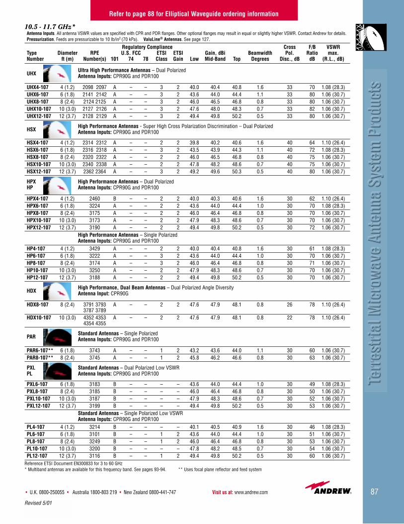
87
10.5 - 11.7 GHz*Antenna Inputs. All antenna VSWR values are specified with CPR and PDR flanges. Other optional flanges may result in equal or slightly higher VSWR. Contact Andrew for details.Pressurization. Feeds are pressurizable to 10 lb/in2 (70 kPa). ValuLine® Antennas. See page 127.
Regulatory Compliance Cross F/B VSWRType Diameter RPE U.S. FCC ETSI ETSI Gain, dBi Beamwidth Pol. Ratio max.Number ft (m) Number(s) 101 74 78 Class Gain Low Mid-Band Top Degrees Disc., dB dB (R.L., dB)
UHXUltra High Performance Antennas – Dual PolarizedAntenna Inputs: CPR90G and PDR100
UHX4-107 4 (1.2) 2098 2097 A – – 3 2 40.0 40.4 40.8 1.6 33 70 1.08 (28.3)UHX6-107 6 (1.8) 2141 2142 A – – 3 2 43.6 44.0 44.4 1.1 33 80 1.06 (30.7)UHX8-107 8 (2.4) 2124 2125 A – – 3 2 46.0 46.5 46.8 0.8 33 80 1.06 (30.7)UHX10-107 10 (3.0) 2127 2126 A – – 3 2 47.6 48.0 48.3 0.7 33 82 1.06 (30.7)UHX12-107 12 (3.7) 2128 2129 A – – 3 2 49.4 49.8 50.2 0.5 33 80 1.06 (30.7)
HSXHigh Performance Antennas - Super High Cross Polarization Discrimination – Dual PolarizedAntenna Inputs: CPR90G and PDR100
HSX4-107 4 (1.2) 2314 2312 A – – 2 2 39.8 40.2 40.6 1.6 40 64 1.10 (26.4)HSX6-107 6 (1.8) 2316 2318 A – – 3 2 43.5 43.9 44.3 1.1 40 72 1.08 (28.3)HSX8-107 8 (2.4) 2320 2322 A – – 2 2 46.0 46.5 46.8 0.8 40 75 1.06 (30.7)HSX10-107 10 (3.0) 2340 2338 A – – 2 2 47.8 48.2 48.6 0.7 40 75 1.06 (30.7)HSX12-107 12 (3.7) 2362 2364 A – – 3 2 49.2 49.6 50.3 0.5 40 80 1.06 (30.7)
HPX High Performance Antennas – Dual PolarizedHP Antenna Inputs: CPR90G and PDR100
HPX4-107 4 (1.2) 2460 B – – 2 2 40.0 40.3 40.6 1.6 30 62 1.10 (26.4)HPX6-107 6 (1.8) 3224 A – – 2 2 43.6 44.0 44.4 1.0 30 70 1.08 (28.3)HPX8-107 8 (2.4) 3175 A – – 2 2 46.0 46.4 46.8 0.8 30 70 1.06 (30.7)HPX10-107 10 (3.0) 3173 A – – 2 2 47.9 48.3 48.6 0.7 30 70 1.06 (30.7)HPX12-107 12 (3.7) 3190 A – – 2 2 49.4 49.8 50.2 0.5 30 72 1.06 (30.7)
High Performance Antennas – Single PolarizedAntenna Inputs: CPR90G and PDR100
HP4-107 4 (1.2) 3429 A – – 2 2 40.0 40.4 40.8 1.6 30 61 1.08 (28.3)HP6-107 6 (1.8) 3222 A – – 3 2 43.6 44.0 44.4 1.0 30 70 1.06 (30.7)HP8-107 8 (2.4) 3174 A – – 3 2 46.0 46.4 46.8 0.8 30 71 1.06 (30.7)HP10-107 10 (3.0) 3250 A – – 2 2 47.9 48.3 48.6 0.7 30 70 1.06 (30.7)HP12-107 12 (3.7) 3188 A – – 2 2 49.4 49.8 50.2 0.5 30 70 1.06 (30.7)
HDXHigh Performance, Dual Beam Antennas – Dual Polarized Angle DiversityAntenna Input: CPR90G
HDX8-107 8 (2.4) 3791 3793 A – – 2 2 47.6 47.9 48.1 0.8 26 78 1.10 (26.4)3787 3789
HDX10-107 10 (3.0) 4352 4353 A – – 2 2 47.6 47.9 48.1 0.8 22 78 1.10 (26.4)4354 4355
PARStandard Antennas – Single PolarizedAntenna Inputs: CPR90G and PDR100
PAR6-107** 6 (1.8) 3743 A – – 1 2 43.2 43.6 44.0 1.1 30 60 1.06 (30.7)PAR8-107** 8 (2.4) 3745 A – – 1 2 45.8 46.2 46.6 0.8 30 63 1.06 (30.7)
PXL Standard Antennas – Dual Polarized Low VSWRPL Antenna Inputs: CPR90G and PDR100
PXL6-107 6 (1.8) 3183 B – – – – 43.6 44.0 44.4 1.0 30 49 1.08 (28.3)PXL8-107 8 (2.4) 3185 B – – – – 46.0 46.4 46.8 0.8 30 50 1.06 (30.7)PXL10-107 10 (3.0) 3187 B – – – – 47.9 48.3 48.6 0.7 30 52 1.06 (30.7)PXL12-107 12 (3.7) 3199 B – – – – 49.4 49.8 50.2 0.5 30 53 1.06 (30.7)
Standard Antennas – Single Polarized Low VSWRAntenna Inputs: CPR90G and PDR100
PL4-107 4 (1.2) 3214 B – – – – 40.1 40.5 40.9 1.6 30 46 1.08 (28.3)PL6-107 6 (1.8) 3101 B – – 1 2 43.6 44.0 44.4 1.0 30 51 1.06 (30.7)PL8-107 8 (2.4) 3249 B – – 1 2 46.0 46.4 46.8 0.8 30 53 1.06 (30.7)PL10-107 10 (3.0) 3200 B – – – – 47.8 48.2 48.5 0.7 30 54 1.06 (30.7)PL12-107 12 (3.7) 3116 B – – 1 2 49.4 49.8 50.2 0.5 30 60 1.06 (30.7)
Reference ETSI Document EN300833 for 3 to 60 GHz* Multiband antennas are available for this frequency band. See pages 93-94. ** Uses focal plane reflector and feed system
• U.K. 0800-250055 • Australia 1800-803 219 • New Zealand 0800-441-747 Visit us at: www.andrew.com
Refer to page 88 for Elliptical Waveguide ordering information
Revised 5/01
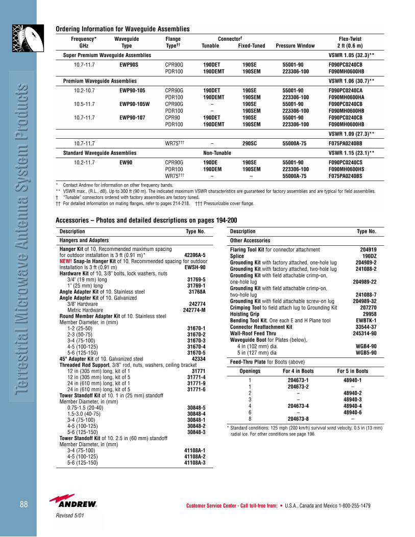
Customer Service Center - Call toll-free from: • U.S.A., Canada and Mexico 1-800-255-147988
Ordering Information for Waveguide AssembliesFrequency* Waveguide Flange Connector† Flex-Twist
GHz Type Type†† Tunable Fixed-Tuned Pressure Window 2 ft (0.6 m)
Super Premium Waveguide Assemblies VSWR 1.05 (32.3)**
10.7-11.7 EWP90S CPR90G 190DET 190SE 55001-90 F090PC0240CBPDR100 190DEMT 190SEM 223306-100 F090MH0600HB
Premium Waveguide Assemblies VSWR 1.06 (30.7)**
10.2-10.7 EWP90-105 CPR90G 190DET 190SE 55001-90 F090PC0240CAPDR100 190DEMT 190SEM 223306-100 F090MH0600HA
10.5-11.7 EWP90-105W CPR90G – 190SE 55001-90 F090PC0240CBPDR100 – 190SEM 223306-100 F090MH0600HB
10.7-11.7 EWP90-107 CPR90 190DET 190SE 55001-90 F090PC0240CBPDR100 190DEMT 190SEM 223306-100 F090MH0600HB
VSWR 1.09 (27.3)**
10.7-11.7 WR75††† – 290SC 55000A-75 F075PA0240BB
Standard Waveguide Assemblies Non-Tunable VSWR 1.15 (23.1)**
10.2-11.7 EW90 CPR90G 190DE 190SE 55001-90 F090PC0240CSPDR100 190DEM 190SEM 223306-100 F090MH0600HSWR75††† – – 55000A-75 F075PA0240BS
* Contact Andrew for information on other frequency bands. ** VSWR max., (R.L., dB). Up to 300 ft (90 m). The indicated maximum VSWR characteristics are guaranteed for factory assemblies and are typical for field assemblies.† “Tunable” connectors ordered with factory assemblies are factory tuned. †† For detailed information on mating flanges, refer to pages 214-218. ††† Pressurizable cover flange.
Description Type No.
Hangers and Adapters
Hanger Kit of 10, Recommended maximum spacingfor outdoor installation is 3 ft (0.91 m)* 42396A-5NEW! Snap-In Hanger Kit of 10. Recommended spacing for outdoor installation is 3 ft (0.91 m) EWSH-90Hardware Kit of 10, 3/8" bolts, lock washers, nuts
3/4" (19 mm) long 31769-51" (25 mm) long 31769-1
Angle Adapter Kit of 10. Stainless steel 31768AAngle Adapter Kit of 10. Galvanized
3/8" Hardware 242774Metric Hardware 242774-M
Round Member Adapter Kit of 10. Stainless steelMember Diameter, in (mm)
1-2 (25-50) 31670-12-3 (50-75) 31670-23-4 (75-100) 31670-34-5 (100-125) 31670-45-6 (125-150) 31670-5
45° Adapter Kit of 10. Galvanized steel 42334Threaded Rod Support, 3/8” rod, nuts, washers, ceiling bracket
12 in (305 mm) long, kit of 1 3177112 in (305 mm) long, kit of 5 31771-424 in (610 mm) long, kit of 1 31771-924 in (610 mm) long, kit of 5 31771-6
Tower Standoff Kit of 10. 1 in (25 mm) standoffMember Diameter, in (mm)
0.75-1.5 (20-40) 30848-51.5-3.0 (40-75) 30848-43-4 (75-100) 30848-14-5 (100-125) 30848-25-6 (125-150) 30848-3
Tower Standoff Kit of 10. 2.5 in (60 mm) standoffMember Diameter, in (mm)
3-4 (75-100) 41108A-14-5 (100-125) 41108A-25-6 (125-150) 41108A-3
Description Type No.
Other Accessories
Flaring Tool Kit for connector attachment 204919Splice 190DZGrounding Kit with factory attached, one-hole lug 204989-2Grounding Kit with factory attached, two-hole lug 241088-2Grounding Kit with field attachable crimp-on, one-hole lug 204989-22Grounding Kit with field attachable crimp-on, two-hole lug 241088-7Grounding Kit with field attachable screw-on lug 204989-32Crimping Tool to field attach lug to Grounding Kit 207270Hoisting Grip 29958Bending Tool Kit. One each E and H Plane tool EWBTK-1Connector Reattachment Kit 33544-37Wall-Roof Feed Thru 245314-90Waveguide Boot for Plates (below),
4 in (102 mm) dia. WGB4-905 in (127 mm) dia WGB5-90
Feed-Thru Plate for Boots (above)
Openings For 4 in Boots For 5 in Boots
1 204673-1 48940-11 204673-2 –2 – 48940-23 – 48940-34 204673-4 48940-46 – 48940-68 204673-8 –
* Standard conditions: 125 mph (200 km/h) survival wind velocity, 0.5 in (13 mm) radial ice. For other conditions see page 196.
Accessories – Photos and detailed descriptions on pages 194-200
Revised 5/01
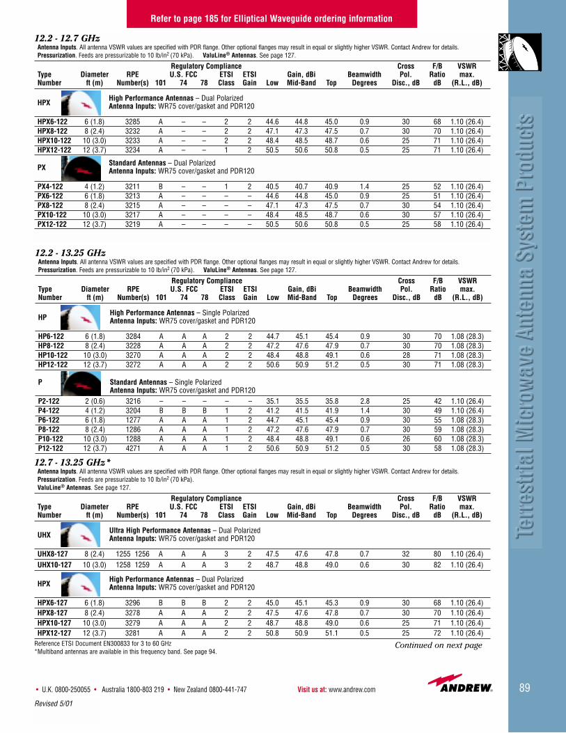
• U.K. 0800-250055 • Australia 1800-803 219 • New Zealand 0800-441-747 Visit us at: www.andrew.com 89
12.2 - 13.25 GHzAntenna Inputs. All antenna VSWR values are specified with PDR flange. Other optional flanges may result in equal or slightly higher VSWR. Contact Andrew for details.Pressurization. Feeds are pressurizable to 10 lb/in2 (70 kPa). ValuLine® Antennas. See page 127.
Regulatory Compliance Cross F/B VSWRType Diameter RPE U.S. FCC ETSI ETSI Gain, dBi Beamwidth Pol. Ratio max.Number ft (m) Number(s) 101 74 78 Class Gain Low Mid-Band Top Degrees Disc., dB dB (R.L., dB)
HPHigh Performance Antennas – Single PolarizedAntenna Inputs: WR75 cover/gasket and PDR120
HP6-122 6 (1.8) 3284 A A A 2 2 44.7 45.1 45.4 0.9 30 70 1.08 (28.3)HP8-122 8 (2.4) 3228 A A A 2 2 47.2 47.6 47.9 0.7 30 70 1.08 (28.3)HP10-122 10 (3.0) 3270 A A A 2 2 48.4 48.8 49.1 0.6 28 71 1.08 (28.3)HP12-122 12 (3.7) 3272 A A A 2 2 50.6 50.9 51.2 0.5 30 71 1.08 (28.3)
P Standard Antennas – Single PolarizedAntenna Inputs: WR75 cover/gasket and PDR120
P2-122 2 (0.6) 3216 – – – – – 35.1 35.5 35.8 2.8 25 42 1.10 (26.4)P4-122 4 (1.2) 3204 B B B 1 2 41.2 41.5 41.9 1.4 30 49 1.10 (26.4)P6-122 6 (1.8) 1277 A A A 1 2 44.7 45.1 45.4 0.9 30 55 1.08 (28.3)P8-122 8 (2.4) 1286 A A A 1 2 47.2 47.6 47.9 0.7 30 59 1.08 (28.3)P10-122 10 (3.0) 1288 A A A 1 2 48.4 48.8 49.1 0.6 26 60 1.08 (28.3)P12-122 12 (3.7) 4271 A A A 1 2 50.6 50.9 51.2 0.5 30 58 1.08 (28.3)
12.7 - 13.25 GHz*Antenna Inputs. All antenna VSWR values are specified with PDR flange. Other optional flanges may result in equal or slightly higher VSWR. Contact Andrew for details.Pressurization. Feeds are pressurizable to 10 lb/in2 (70 kPa).ValuLine® Antennas. See page 127.
Regulatory Compliance Cross F/B VSWRType Diameter RPE U.S. FCC ETSI ETSI Gain, dBi Beamwidth Pol. Ratio max.Number ft (m) Number(s) 101 74 78 Class Gain Low Mid-Band Top Degrees Disc., dB dB (R.L., dB)
UHXUltra High Performance Antennas – Dual PolarizedAntenna Inputs: WR75 cover/gasket and PDR120
UHX8-127 8 (2.4) 1255 1256 A A A 3 2 47.5 47.6 47.8 0.7 32 80 1.10 (26.4)UHX10-127 10 (3.0) 1258 1259 A A A 3 2 48.7 48.8 49.0 0.6 30 82 1.10 (26.4)
HPXHigh Performance Antennas – Dual PolarizedAntenna Inputs: WR75 cover/gasket and PDR120
HPX6-127 6 (1.8) 3296 B B B 2 2 45.0 45.1 45.3 0.9 30 68 1.10 (26.4)HPX8-127 8 (2.4) 3278 A A A 2 2 47.5 47.6 47.8 0.7 30 70 1.10 (26.4)HPX10-127 10 (3.0) 3279 A A A 2 2 48.7 48.8 49.0 0.6 25 71 1.10 (26.4)HPX12-127 12 (3.7) 3281 A A A 2 2 50.8 50.9 51.1 0.5 25 72 1.10 (26.4)
Reference ETSI Document EN300833 for 3 to 60 GHz*Multiband antennas are available in this frequency band. See page 94.
Refer to page 185 for Elliptical Waveguide ordering information
12.2 - 12.7 GHzAntenna Inputs. All antenna VSWR values are specified with PDR flange. Other optional flanges may result in equal or slightly higher VSWR. Contact Andrew for details.Pressurization. Feeds are pressurizable to 10 lb/in2 (70 kPa). ValuLine® Antennas. See page 127.
Regulatory Compliance Cross F/B VSWRType Diameter RPE U.S. FCC ETSI ETSI Gain, dBi Beamwidth Pol. Ratio max.Number ft (m) Number(s) 101 74 78 Class Gain Low Mid-Band Top Degrees Disc., dB dB (R.L., dB)
HPXHigh Performance Antennas – Dual PolarizedAntenna Inputs: WR75 cover/gasket and PDR120
HPX6-122 6 (1.8) 3285 A – – 2 2 44.6 44.8 45.0 0.9 30 68 1.10 (26.4)HPX8-122 8 (2.4) 3232 A – – 2 2 47.1 47.3 47.5 0.7 30 70 1.10 (26.4)HPX10-122 10 (3.0) 3233 A – – 2 2 48.4 48.5 48.7 0.6 25 71 1.10 (26.4)HPX12-122 12 (3.7) 3234 A – – 1 2 50.5 50.6 50.8 0.5 25 71 1.10 (26.4)
PXStandard Antennas – Dual PolarizedAntenna Inputs: WR75 cover/gasket and PDR120
PX4-122 4 (1.2) 3211 B – – 1 2 40.5 40.7 40.9 1.4 25 52 1.10 (26.4)PX6-122 6 (1.8) 3213 A – – – – 44.6 44.8 45.0 0.9 25 51 1.10 (26.4)PX8-122 8 (2.4) 3215 A – – – – 47.1 47.3 47.5 0.7 30 54 1.10 (26.4)PX10-122 10 (3.0) 3217 A – – – – 48.4 48.5 48.7 0.6 30 57 1.10 (26.4)PX12-122 12 (3.7) 3219 A – – – – 50.5 50.6 50.8 0.5 25 58 1.10 (26.4)
Continued on next page
Revised 5/01
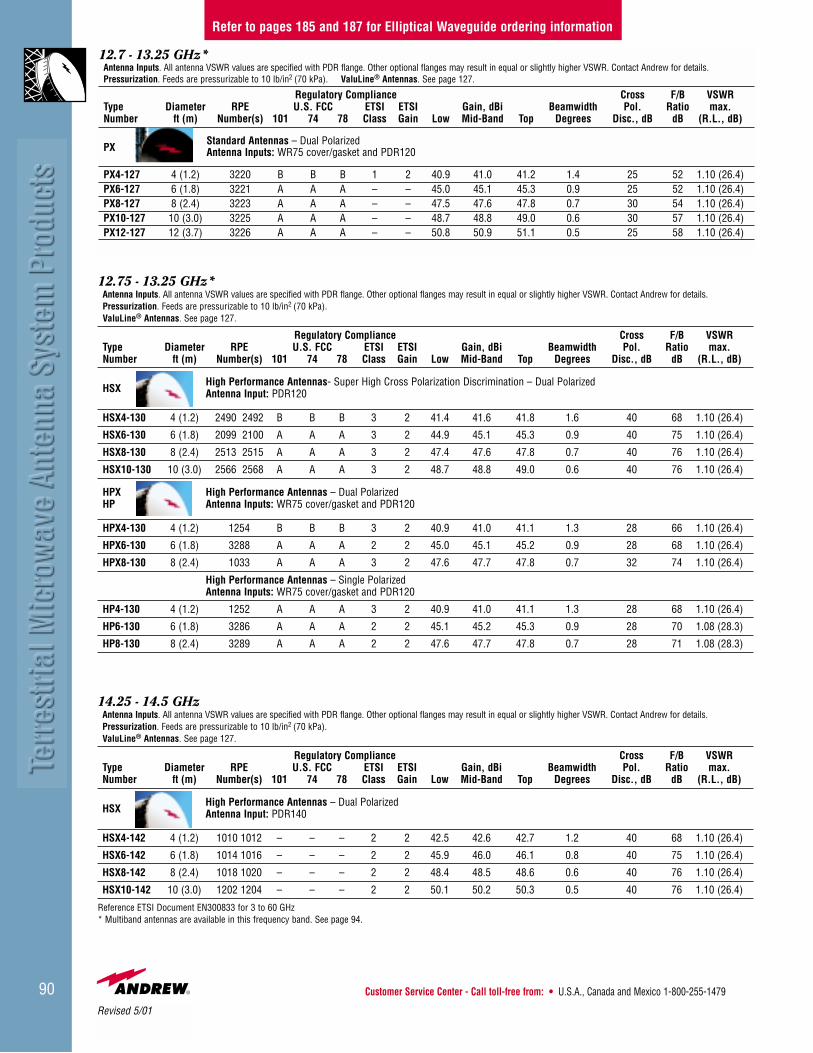
Customer Service Center - Call toll-free from: • U.S.A., Canada and Mexico 1-800-255-147990
12.75 - 13.25 GHz*Antenna Inputs. All antenna VSWR values are specified with PDR flange. Other optional flanges may result in equal or slightly higher VSWR. Contact Andrew for details.Pressurization. Feeds are pressurizable to 10 lb/in2 (70 kPa).ValuLine® Antennas. See page 127.
Regulatory Compliance Cross F/B VSWRType Diameter RPE U.S. FCC ETSI ETSI Gain, dBi Beamwidth Pol. Ratio max.Number ft (m) Number(s) 101 74 78 Class Gain Low Mid-Band Top Degrees Disc., dB dB (R.L., dB)
HSXHigh Performance Antennas- Super High Cross Polarization Discrimination – Dual PolarizedAntenna Input: PDR120
HSX4-130 4 (1.2) 2490 2492 B B B 3 2 41.4 41.6 41.8 1.6 40 68 1.10 (26.4)
HSX6-130 6 (1.8) 2099 2100 A A A 3 2 44.9 45.1 45.3 0.9 40 75 1.10 (26.4)
HSX8-130 8 (2.4) 2513 2515 A A A 3 2 47.4 47.6 47.8 0.7 40 76 1.10 (26.4)
HSX10-130 10 (3.0) 2566 2568 A A A 3 2 48.7 48.8 49.0 0.6 40 76 1.10 (26.4)
HPX High Performance Antennas – Dual PolarizedHP Antenna Inputs: WR75 cover/gasket and PDR120
HPX4-130 4 (1.2) 1254 B B B 3 2 40.9 41.0 41.1 1.3 28 66 1.10 (26.4)
HPX6-130 6 (1.8) 3288 A A A 2 2 45.0 45.1 45.2 0.9 28 68 1.10 (26.4)
HPX8-130 8 (2.4) 1033 A A A 3 2 47.6 47.7 47.8 0.7 32 74 1.10 (26.4)
High Performance Antennas – Single PolarizedAntenna Inputs: WR75 cover/gasket and PDR120
HP4-130 4 (1.2) 1252 A A A 3 2 40.9 41.0 41.1 1.3 28 68 1.10 (26.4)
HP6-130 6 (1.8) 3286 A A A 2 2 45.1 45.2 45.3 0.9 28 70 1.08 (28.3)
HP8-130 8 (2.4) 3289 A A A 2 2 47.6 47.7 47.8 0.7 28 71 1.08 (28.3)
14.25 - 14.5 GHzAntenna Inputs. All antenna VSWR values are specified with PDR flange. Other optional flanges may result in equal or slightly higher VSWR. Contact Andrew for details.Pressurization. Feeds are pressurizable to 10 lb/in2 (70 kPa).ValuLine® Antennas. See page 127.
Regulatory Compliance Cross F/B VSWRType Diameter RPE U.S. FCC ETSI ETSI Gain, dBi Beamwidth Pol. Ratio max.Number ft (m) Number(s) 101 74 78 Class Gain Low Mid-Band Top Degrees Disc., dB dB (R.L., dB)
HSXHigh Performance Antennas – Dual PolarizedAntenna Input: PDR140
HSX4-142 4 (1.2) 1010 1012 – – – 2 2 42.5 42.6 42.7 1.2 40 68 1.10 (26.4)
HSX6-142 6 (1.8) 1014 1016 – – – 2 2 45.9 46.0 46.1 0.8 40 75 1.10 (26.4)
HSX8-142 8 (2.4) 1018 1020 – – – 2 2 48.4 48.5 48.6 0.6 40 76 1.10 (26.4)
HSX10-142 10 (3.0) 1202 1204 – – – 2 2 50.1 50.2 50.3 0.5 40 76 1.10 (26.4)
Reference ETSI Document EN300833 for 3 to 60 GHz* Multiband antennas are available in this frequency band. See page 94.
Refer to pages 185 and 187 for Elliptical Waveguide ordering information
12.7 - 13.25 GHz*Antenna Inputs. All antenna VSWR values are specified with PDR flange. Other optional flanges may result in equal or slightly higher VSWR. Contact Andrew for details.Pressurization. Feeds are pressurizable to 10 lb/in2 (70 kPa). ValuLine® Antennas. See page 127.
Regulatory Compliance Cross F/B VSWRType Diameter RPE U.S. FCC ETSI ETSI Gain, dBi Beamwidth Pol. Ratio max.Number ft (m) Number(s) 101 74 78 Class Gain Low Mid-Band Top Degrees Disc., dB dB (R.L., dB)
PXStandard Antennas – Dual PolarizedAntenna Inputs: WR75 cover/gasket and PDR120
PX4-127 4 (1.2) 3220 B B B 1 2 40.9 41.0 41.2 1.4 25 52 1.10 (26.4)PX6-127 6 (1.8) 3221 A A A – – 45.0 45.1 45.3 0.9 25 52 1.10 (26.4)PX8-127 8 (2.4) 3223 A A A – – 47.5 47.6 47.8 0.7 30 54 1.10 (26.4)PX10-127 10 (3.0) 3225 A A A – – 48.7 48.8 49.0 0.6 30 57 1.10 (26.4)PX12-127 12 (3.7) 3226 A A A – – 50.8 50.9 51.1 0.5 25 58 1.10 (26.4)
Revised 5/01
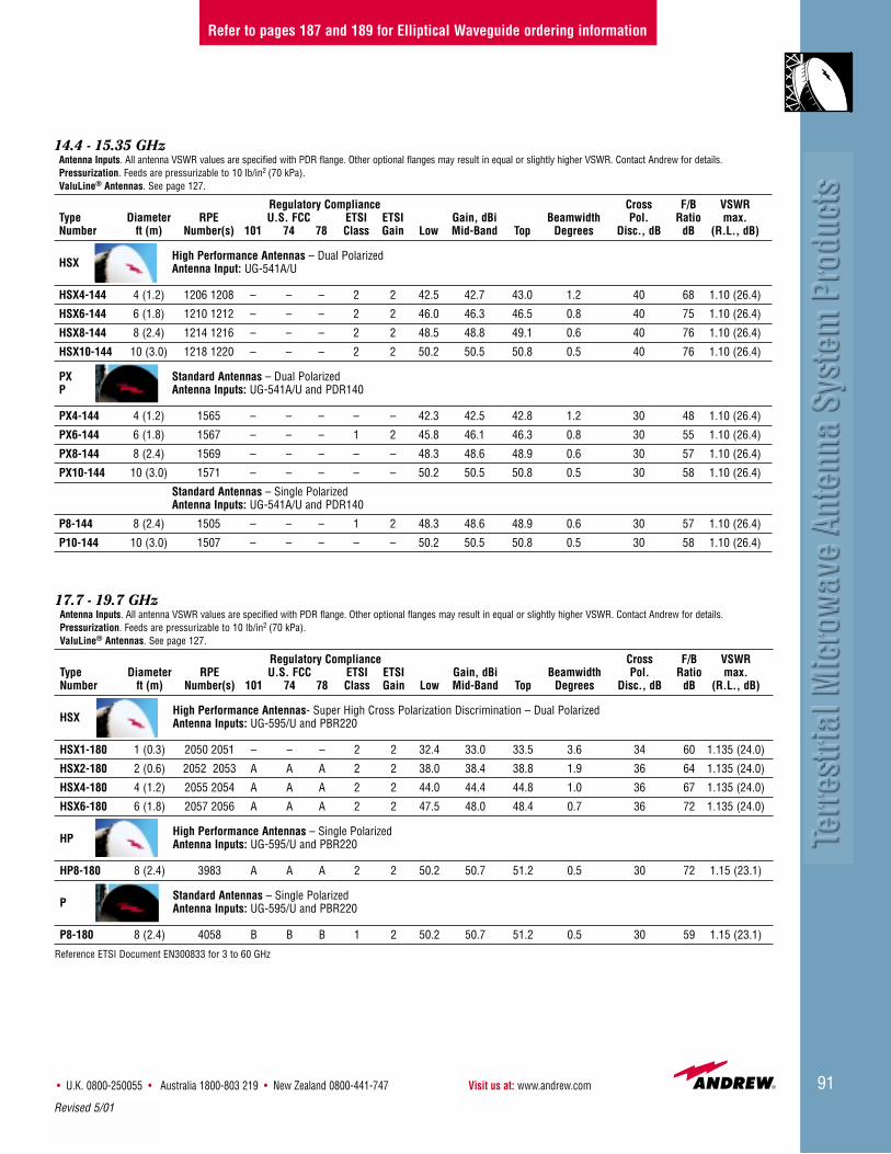
• U.K. 0800-250055 • Australia 1800-803 219 • New Zealand 0800-441-747 Visit us at: www.andrew.com 91
14.4 - 15.35 GHzAntenna Inputs. All antenna VSWR values are specified with PDR flange. Other optional flanges may result in equal or slightly higher VSWR. Contact Andrew for details.Pressurization. Feeds are pressurizable to 10 lb/in2 (70 kPa).ValuLine® Antennas. See page 127.
Regulatory Compliance Cross F/B VSWRType Diameter RPE U.S. FCC ETSI ETSI Gain, dBi Beamwidth Pol. Ratio max.Number ft (m) Number(s) 101 74 78 Class Gain Low Mid-Band Top Degrees Disc., dB dB (R.L., dB)
HSXHigh Performance Antennas – Dual PolarizedAntenna Input: UG-541A/U
HSX4-144 4 (1.2) 1206 1208 – – – 2 2 42.5 42.7 43.0 1.2 40 68 1.10 (26.4)
HSX6-144 6 (1.8) 1210 1212 – – – 2 2 46.0 46.3 46.5 0.8 40 75 1.10 (26.4)
HSX8-144 8 (2.4) 1214 1216 – – – 2 2 48.5 48.8 49.1 0.6 40 76 1.10 (26.4)
HSX10-144 10 (3.0) 1218 1220 – – – 2 2 50.2 50.5 50.8 0.5 40 76 1.10 (26.4)
PX Standard Antennas – Dual PolarizedP Antenna Inputs: UG-541A/U and PDR140
PX4-144 4 (1.2) 1565 – – – – – 42.3 42.5 42.8 1.2 30 48 1.10 (26.4)
PX6-144 6 (1.8) 1567 – – – 1 2 45.8 46.1 46.3 0.8 30 55 1.10 (26.4)
PX8-144 8 (2.4) 1569 – – – – – 48.3 48.6 48.9 0.6 30 57 1.10 (26.4)
PX10-144 10 (3.0) 1571 – – – – – 50.2 50.5 50.8 0.5 30 58 1.10 (26.4)
Standard Antennas – Single PolarizedAntenna Inputs: UG-541A/U and PDR140
P8-144 8 (2.4) 1505 – – – 1 2 48.3 48.6 48.9 0.6 30 57 1.10 (26.4)
P10-144 10 (3.0) 1507 – – – – – 50.2 50.5 50.8 0.5 30 58 1.10 (26.4)
17.7 - 19.7 GHzAntenna Inputs. All antenna VSWR values are specified with PDR flange. Other optional flanges may result in equal or slightly higher VSWR. Contact Andrew for details.Pressurization. Feeds are pressurizable to 10 lb/in2 (70 kPa).ValuLine® Antennas. See page 127.
Regulatory Compliance Cross F/B VSWRType Diameter RPE U.S. FCC ETSI ETSI Gain, dBi Beamwidth Pol. Ratio max.Number ft (m) Number(s) 101 74 78 Class Gain Low Mid-Band Top Degrees Disc., dB dB (R.L., dB)
HSXHigh Performance Antennas- Super High Cross Polarization Discrimination – Dual PolarizedAntenna Inputs: UG-595/U and PBR220
HSX1-180 1 (0.3) 2050 2051 – – – 2 2 32.4 33.0 33.5 3.6 34 60 1.135 (24.0)
HSX2-180 2 (0.6) 2052 2053 A A A 2 2 38.0 38.4 38.8 1.9 36 64 1.135 (24.0)
HSX4-180 4 (1.2) 2055 2054 A A A 2 2 44.0 44.4 44.8 1.0 36 67 1.135 (24.0)
HSX6-180 6 (1.8) 2057 2056 A A A 2 2 47.5 48.0 48.4 0.7 36 72 1.135 (24.0)
HPHigh Performance Antennas – Single PolarizedAntenna Inputs: UG-595/U and PBR220
HP8-180 8 (2.4) 3983 A A A 2 2 50.2 50.7 51.2 0.5 30 72 1.15 (23.1)
PStandard Antennas – Single PolarizedAntenna Inputs: UG-595/U and PBR220
P8-180 8 (2.4) 4058 B B B 1 2 50.2 50.7 51.2 0.5 30 59 1.15 (23.1)
Reference ETSI Document EN300833 for 3 to 60 GHz
Refer to pages 187 and 189 for Elliptical Waveguide ordering information
Revised 5/01
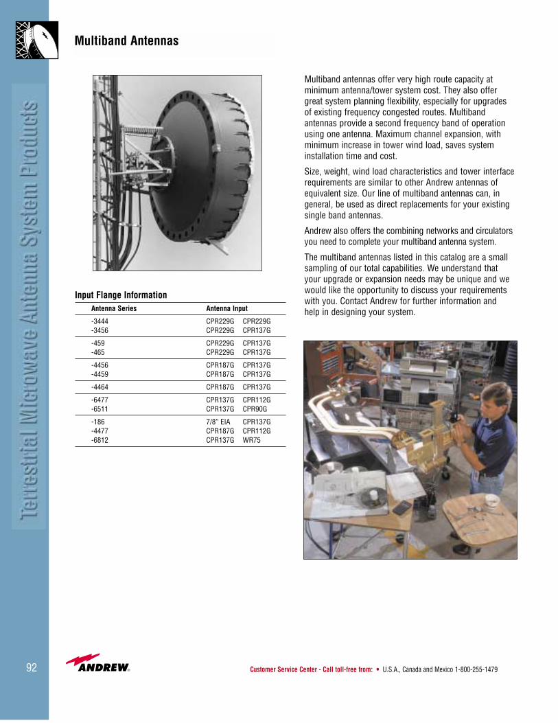
Customer Service Center - Call toll-free from: • U.S.A., Canada and Mexico 1-800-255-147992
Multiband antennas offer very high route capacity at minimum antenna/tower system cost. They also offergreat system planning flexibility, especially for upgradesof existing frequency congested routes. Multiband antennas provide a second frequency band of operationusing one antenna. Maximum channel expansion, withminimum increase in tower wind load, saves systeminstallation time and cost.
Size, weight, wind load characteristics and tower interfacerequirements are similar to other Andrew antennas ofequivalent size. Our line of multiband antennas can, ingeneral, be used as direct replacements for your existingsingle band antennas.
Andrew also offers the combining networks and circulatorsyou need to complete your multiband antenna system.
The multiband antennas listed in this catalog are a smallsampling of our total capabilities. We understand thatyour upgrade or expansion needs may be unique and wewould like the opportunity to discuss your requirementswith you. Contact Andrew for further information andhelp in designing your system.
Input Flange InformationAntenna Series Antenna Input
-3444 CPR229G CPR229G-3456 CPR229G CPR137G
-459 CPR229G CPR137G-465 CPR229G CPR137G
-4456 CPR187G CPR137G-4459 CPR187G CPR137G
-4464 CPR187G CPR137G
-6477 CPR137G CPR112G-6511 CPR137G CPR90G
-186 7/8” EIA CPR137G-4477 CPR187G CPR112G-6812 CPR137G WR75
Multiband Antennas
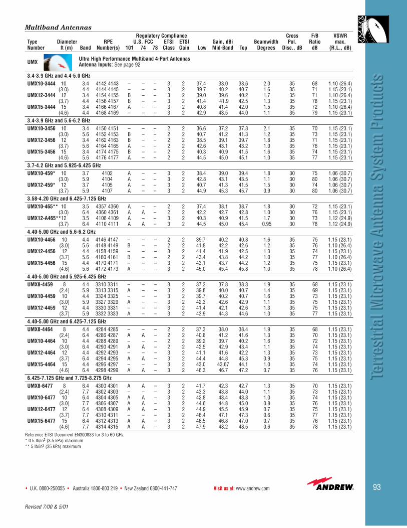
• U.K. 0800-250055 • Australia 1800-803 219 • New Zealand 0800-441-747 Visit us at: www.andrew.com 93
Multiband AntennasRegulatory Compliance Cross F/B VSWR
Type Diameter RPE U.S. FCC ETSI ETSI Gain, dBi Beamwidth Pol. Ratio max.Number ft (m) Band Number(s) 101 74 78 Class Gain Low Mid-Band Top Degrees Disc., dB dB (R.L., dB)
UMXUltra High Performance Multiband 4-Port AntennasAntenna Inputs: See page 92
3.4-3.9 GHz and 4.4-5.0 GHzUMX10-3444 10 3.4 4142 4143 – – – 3 2 37.4 38.0 38.6 2.0 35 68 1.10 (26.4)
(3.0) 4.4 4144 4145 – – – 3 2 39.7 40.2 40.7 1.6 35 71 1.15 (23.1)UMX12-3444 12 3.4 4154 4155 B – – 3 2 39.0 39.6 40.2 1.7 35 71 1.10 (26.4)
(3.7) 4.4 4156 4157 B – – 3 2 41.4 41.9 42.5 1.3 35 78 1.15 (23.1)UMX15-3444 15 3.4 4166 4167 A – – 3 2 40.8 41.4 42.0 1.5 35 72 1.10 (26.4)
(4.6) 4.4 4168 4169 – – – 3 2 42.9 43.5 44.0 1.1 35 79 1.15 (23.1)3.4-3.9 GHz and 5.6-6.2 GHzUMX10-3456 10 3.4 4150 4151 – – – 2 2 36.6 37.2 37.8 2.1 35 70 1.15 (23.1)
(3.0) 5.6 4152 4153 B – – 2 2 40.7 41.2 41.3 1.2 35 73 1.15 (23.1) UMX12-3456 12 3.4 4162 4163 B – – 2 2 38.5 39.1 39.7 1.8 35 71 1.15 (23.1)
(3.7) 5.6 4164 4165 A – – 2 2 42.6 43.1 43.2 1.0 35 76 1.15 (23.1)UMX15-3456 15 3.4 4174 4175 B – – 2 2 40.3 40.9 41.5 1.6 35 74 1.15 (23.1)
(4.6) 5.6 4176 4177 A – – 2 2 44.5 45.0 45.1 1.0 35 77 1.15 (23.1)3.7-4.2 GHz and 5.925-6.425 GHzUMX10-459* 10 3.7 4102 A – – 3 2 38.4 39.0 39.4 1.8 30 75 1.06 (30.7)
(3.0) 5.9 4104 A – – 3 2 42.8 43.1 43.5 1.1 30 80 1.06 (30.7)UMX12-459* 12 3.7 4105 A – – 3 2 40.7 41.3 41.5 1.5 30 74 1.06 (30.7)
(3.7) 5.9 4107 A – – 3 2 44.9 45.3 45.7 0.9 30 80 1.06 (30.7)3.58-4.20 GHz and 6.425-7.125 GHzUMX10-465** 10 3.5 4357 4360 A – – 2 2 37.4 38.1 38.7 1.8 30 72 1.15 (23.1)
(3.0) 6.4 4360 4361 A A – 2 2 42.2 42.7 42.8 1.0 30 76 1.15 (23.1)UMX12-A465**12 3.5 4108 4109 A – – 3 2 40.3 40.9 41.5 1.7 30 73 1.12 (24.9)
(3.7) 6.4 4110 4111 A A – 3 2 44.5 45.0 45.4 0.95 30 78 1.12 (24.9)4.40-5.00 GHz and 5.6-6.2 GHzUMX10-4456 10 4.4 4146 4147 – – – 2 2 39.7 40.2 40.8 1.6 35 75 1.15 (23.1)
(3.0) 5.6 4148 4149 B – – 2 2 41.8 42.2 42.6 1.2 35 76 1.10 (26.4)UMX12-4456 12 4.4 4158 4159 – – – 3 2 41.4 41.9 42.5 1.3 35 74 1.15 (23.1)
(3.7) 5.6 4160 4161 B – – 2 2 43.4 43.8 44.2 1.0 35 77 1.10 (26.4)UMX15-4456 15 4.4 4170 4171 – – – 3 2 43.1 43.7 44.2 1.2 35 75 1.15 (23.1)
(4.6) 5.6 4172 4173 A – – 3 2 45.0 45.4 45.8 1.0 35 78 1.10 (26.4)4.40-5.00 GHz and 5.925-6.425 GHzUMX8-4459 8 4.4 3310 3311 – – – 3 2 37.3 37.8 38.3 1.9 35 68 1.15 (23.1)
(2.4) 5.9 3313 3315 A – – 3 2 39.8 40.0 40.7 1.4 35 69 1.15 (23.1)UMX10-4459 10 4.4 3324 3325 – – – 3 2 39.7 40.2 40.7 1.6 35 73 1.15 (23.1)
(3.0) 5.9 3327 3329 A – – 3 2 42.3 42.6 42.9 1.1 35 75 1.15 (23.1)UMX12-4459 12 4.4 3330 3331 – – – 3 2 41.4 42.1 42.6 1.3 35 75 1.15 (23.1)
(3.7) 5.9 3332 3333 A – – 3 2 43.9 44.3 44.6 1.0 35 77 1.15 (23.1)4.40-5.00 GHz and 6.425-7.125 GHzUMX8-4464 8 4.4 4284 4285 – – – 2 2 37.3 38.0 38.4 1.9 35 68 1.15 (23.1)
(2.4) 6.4 4286 4287 A A – 2 2 40.8 41.2 41.6 1.3 35 70 1.15 (23.1)UMX10-4464 10 4.4 4288 4289 – – – 2 2 39.2 39.7 40.2 1.6 35 72 1.15 (23.1)
(3.0) 6.4 4290 4291 A A – 2 2 42.5 42.9 43.4 1.1 35 74 1.15 (23.1)UMX12-4464 12 4.4 4292 4293 – – – 3 2 41.1 41.6 42.2 1.3 35 73 1.15 (23.1)
(3.7) 6.4 4294 4295 A A – 3 2 44.4 44.8 45.3 0.9 35 75 1.15 (23.1)UMX15-4464 15 4.4 4296 4297 – – – 3 2 43.0 43.67 44.1 1.0 35 74 1.15 (23.1)
(4.6) 6.4 4298 4299 A A – 3 2 46.3 46.7 47.2 0.7 35 76 1.15 (23.1)6.425-7.125 GHz and 7.725-8.275 GHzUMX8-6477 8 6.4 4300 4301 A A – 3 2 41.7 42.3 42.7 1.3 35 70 1.15 (23.1)
(2.4) 7.7 4302 4303 – – – 3 2 43.3 43.8 44.0 1.1 35 73 1.15 (23.1)UMX10-6477 10 6.4 4304 4305 A A – 3 2 42.8 43.4 43.8 1.0 35 74 1.15 (23.1)
(3.0) 7.7 4306 4307 A A – 3 2 44.6 44.8 45.0 0.8 35 76 1.15 (23.1)UMX12-6477 12 6.4 4308 4309 A A – 3 2 44.9 45.5 45.9 0.7 35 75 1.15 (23.1)
(3.7) 7.7 4310 4311 – – – 3 2 46.4 47.1 47.3 0.6 35 77 1.15 (23.1)UMX15-6477 15 6.4 4312 4313 A A – 3 2 46.5 46.8 47.0 0.7 35 76 1.15 (23.1)
(4.6) 7.7 4314 4315 A A – 3 2 47.9 48.2 48.5 0.6 35 78 1.15 (23.1)Reference ETSI Document EN300833 for 3 to 60 GHz* 0.5 lb/in2 (3.5 kPa) maximum** 5 lb/in2 (35 kPa) maximum
Revised 7/00 & 5/01
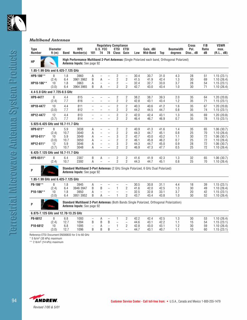
Customer Service Center - Call toll-free from: • U.S.A., Canada and Mexico 1-800-255-147994
Multiband AntennasRegulatory Compliance Cross F/B VSWR
Type Diameter RPE U.S. FCC ETSI ETSI Gain, dBi Beamwidth Pol. Ratio max.Number ft (m) Band Number(s) 101 74 78 Class Gain Low Mid-Band Top degrees Disc., dB dB (R.L., dB)
HPHigh Performance Multiband 2-Port Antennas (Single Polarized each band, Orthogonal Polarized)Antenna Inputs: See page 92
1.85-1.99 GHz and 6.425-7.125 GHz
HP8-186** 8 1.8 3960 A – – 2 – 30.4 30.7 31.0 4.3 28 51 1.15 (23.1)(2.4) 6.4 3961 3962 B A – 2 2 41.5 41.9 42.4 1.3 30 69 1.10 (26.4)
HP10-186** 10 1.8 3963 A – – 2 – 32.4 32.7 33.0 3.7 28 54 1.15 (23.1)(3.0) 6.4 3964 3965 B A – 2 2 42.7 43.0 43.4 1.0 30 71 1.10 (26.4)
4.4-5.0 GHz and 7.725-8.5 GHz
HP8-4477 8 4.4 815 – – – 2 2 38.2 38.7 39.3 2.0 35 64 1.20 (20.8)(2.4) 7.7 816 – – – 2 2 42.8 43.1 43.4 1.2 35 71 1.15 (23.1)
HP10-4477 10 4.4 811 – – – 2 2 40.3 40.6 41.2 1.6 35 67 1.20 (20.8)(3.0) 7.7 812 – – – 2 2 44.2 44.5 44.7 0.8 35 74 1.15 (23.1)
HP12-4477 12 4.4 813 – – – 2 2 42.0 42.4 43.1 1.3 35 69 1.20 (20.8)(3.7) 7.7 814 – – – 2 2 46.4 46.7 46.9 0.7 35 78 1.15 (23.1)
5.925-6.425 GHz and 10.7-11.7 GHz
HP8-611* 8 5.9 3038 A – – 2 2 40.9 41.3 41.6 1.4 35 65 1.06 (30.7)(2.4) 10.7 3040 A – – 2 2 44.3 44.7 45.1 0.8 25 70 1.10 (26.4)
HP10-611* 10 5.9 3049 A – – 3 2 42.7 43.0 43.2 1.1 30 72 1.06 (30.7)(3.0) 10.7 3050 A – – 2 2 46.1 45.8 46.2 0.7 25 72 1.10 (26.4)
HP12-611* 12 5.9 3046 A – – 3 2 44.3 44.7 45.0 0.9 28 72 1.06 (30.7)(3.7) 10.7 3048 A – – 2 2 46.9 47.3 47.7 0.5 25 72 1.10 (26.4)
6.425-7.125 GHz and 10.7-11.7 GHz
HP8-6511* 8 6.4 2387 B A – 2 2 41.6 41.9 42.3 1.3 32 65 1.06 (30.7)(2.4) 10.7 2392 A – – 2 2 44.3 44.7 45.1 0.8 25 70 1.10 (26.4)
PStandard Multiband 3-Port Antennas (2 GHz Single Polarized, 6 GHz Dual Polarized)Antenna Inputs: See page 92
1.85-1.99 GHz and 6.425-7.125 GHz
P8-186** 8 1.8 3945 A – – – – 30.5 30.8 31.1 4.4 18 39 1.15 (23.1)(2.4) 6.4 3946 3947 B B – 1 2 41.6 42.0 42.5 1.3 30 49 1.10 (26.4)
P10-186** 10 1.8 3950 A – – – – 32.5 32.8 33.1 3.7 20 42 1.15 (23.1)(3.0) 6.4 3951 3952 B A – 1 2 43.7 43.4 43.8 1.0 30 52 1.10 (26.4)
PStandard Multiband 2-Port Antennas (Both Bands Single Polarized, Orthogonal Polarization)Antenna Inputs: See page 92
6.875-7.125 GHz and 12.70-13.25 GHz
P8-6812 8 6.8 1093 – A – 1 2 42.2 42.4 42.5 1.3 30 53 1.10 (26.4)(2.4) 12.7 1094 B B B – – 44.6 43.1 42.2 1.1 15 54 1.15 (23.1)
P10-6812 10 6.8 1095 – A – 1 2 42.8 43.0 43.1 1.2 30 59 1.10 (26.4)(3.0) 12.7 1096 B B B – – 44.7 43.1 40.7 1.1 10 60 1.15 (23.1)
Reference ETSI Document EN300833 for 3 to 60 GHz* 5 lb/in2 (35 kPa) maximum** 2 lb/in2 (14 kPa) maximum
Revised 7/00 & 5/01
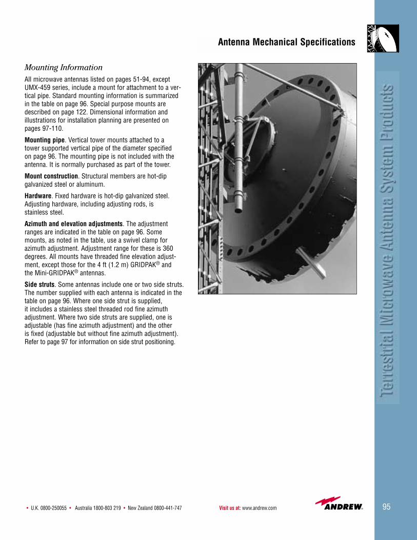
• U.K. 0800-250055 • Australia 1800-803 219 • New Zealand 0800-441-747 Visit us at: www.andrew.com 95
Mounting InformationAll microwave antennas listed on pages 51-94, except UMX-459 series, include a mount for attachment to a ver-tical pipe. Standard mounting information is summarizedin the table on page 96. Special purpose mounts aredescribed on page 122. Dimensional information and illustrations for installation planning are presented onpages 97-110.
Mounting pipe. Vertical tower mounts attached to a tower supported vertical pipe of the diameter specified on page 96. The mounting pipe is not included with theantenna. It is normally purchased as part of the tower.
Mount construction. Structural members are hot-dip galvanized steel or aluminum.
Hardware. Fixed hardware is hot-dip galvanized steel.Adjusting hardware, including adjusting rods, is stainless steel.
Azimuth and elevation adjustments. The adjustmentranges are indicated in the table on page 96. Somemounts, as noted in the table, use a swivel clamp forazimuth adjustment. Adjustment range for these is 360degrees. All mounts have threaded fine elevation adjust-ment, except those for the 4 ft (1.2 m) GRIDPAK® and the Mini-GRIDPAK® antennas.
Side struts. Some antennas include one or two side struts.The number supplied with each antenna is indicated in thetable on page 96. Where one side strut is supplied, it includes a stainless steel threaded rod fine azimuthadjustment. Where two side struts are supplied, one isadjustable (has fine azimuth adjustment) and the other is fixed (adjustable but without fine azimuth adjustment).Refer to page 97 for information on side strut positioning.
Antenna Mechanical Specifications
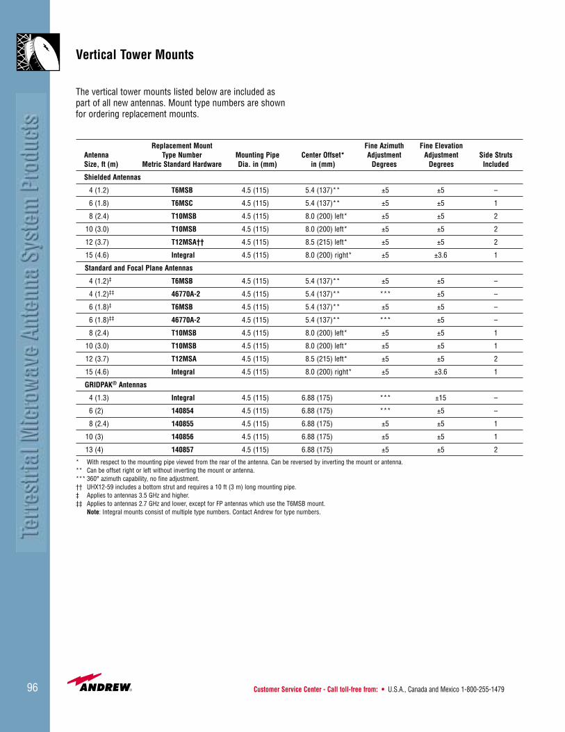
Customer Service Center - Call toll-free from: • U.S.A., Canada and Mexico 1-800-255-147996
The vertical tower mounts listed below are included aspart of all new antennas. Mount type numbers are shownfor ordering replacement mounts.
Vertical Tower Mounts
Replacement Mount Fine Azimuth Fine ElevationAntenna Type Number Mounting Pipe Center Offset* Adjustment Adjustment Side StrutsSize, ft (m) Metric Standard Hardware Dia. in (mm) in (mm) Degrees Degrees Included
Shielded Antennas
4 (1.2) T6MSB 4.5 (115) 5.4 (137)** ±5 ±5 –
6 (1.8) T6MSC 4.5 (115) 5.4 (137)** ±5 ±5 1
8 (2.4) T10MSB 4.5 (115) 8.0 (200) left* ±5 ±5 2
10 (3.0) T10MSB 4.5 (115) 8.0 (200) left* ±5 ±5 2
12 (3.7) T12MSA†† 4.5 (115) 8.5 (215) left* ±5 ±5 2
15 (4.6) Integral 4.5 (115) 8.0 (200) right* ±5 ±3.6 1
Standard and Focal Plane Antennas
4 (1.2)‡ T6MSB 4.5 (115) 5.4 (137)** ±5 ±5 –
4 (1.2)‡‡ 46770A-2 4.5 (115) 5.4 (137)** *** ±5 –
6 (1.8)‡ T6MSB 4.5 (115) 5.4 (137)** ±5 ±5 –
6 (1.8)‡‡ 46770A-2 4.5 (115) 5.4 (137)** *** ±5 –
8 (2.4) T10MSB 4.5 (115) 8.0 (200) left* ±5 ±5 1
10 (3.0) T10MSB 4.5 (115) 8.0 (200) left* ±5 ±5 1
12 (3.7) T12MSA 4.5 (115) 8.5 (215) left* ±5 ±5 2
15 (4.6) Integral 4.5 (115) 8.0 (200) right* ±5 ±3.6 1
GRIDPAK® Antennas
4 (1.3) Integral 4.5 (115) 6.88 (175) *** ±15 –
6 (2) 140854 4.5 (115) 6.88 (175) *** ±5 –
8 (2.4) 140855 4.5 (115) 6.88 (175) ±5 ±5 1
10 (3) 140856 4.5 (115) 6.88 (175) ±5 ±5 1
13 (4) 140857 4.5 (115) 6.88 (175) ±5 ±5 2
* With respect to the mounting pipe viewed from the rear of the antenna. Can be reversed by inverting the mount or antenna.** Can be offset right or left without inverting the mount or antenna.*** 360° azimuth capability, no fine adjustment.†† UHX12-59 includes a bottom strut and requires a 10 ft (3 m) long mounting pipe.‡ Applies to antennas 3.5 GHz and higher. ‡‡ Applies to antennas 2.7 GHz and lower, except for FP antennas which use the T6MSB mount.
Note: Integral mounts consist of multiple type numbers. Contact Andrew for type numbers.
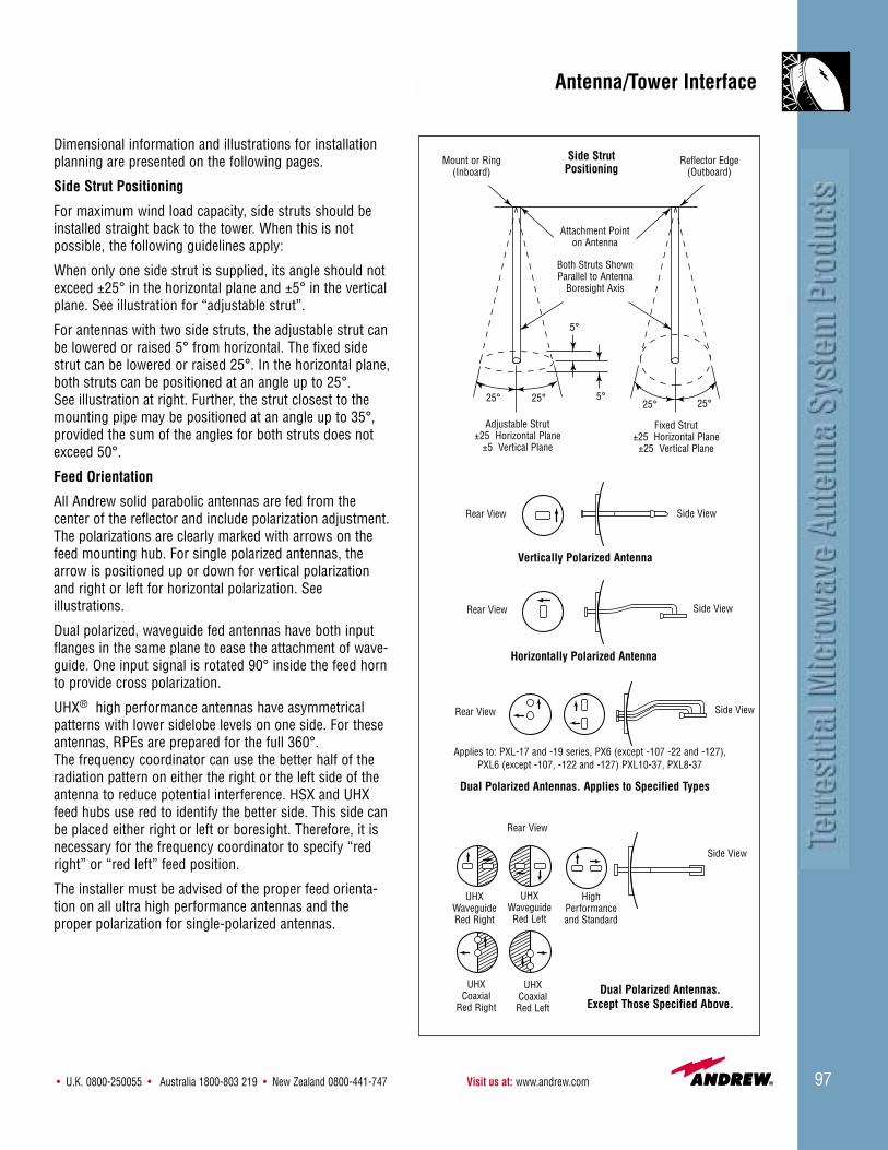
• U.K. 0800-250055 • Australia 1800-803 219 • New Zealand 0800-441-747 Visit us at: www.andrew.com 97
Mount or Ring(Inboard)
Fixed Strut±25 Horizontal Plane
±25 Vertical Plane
Adjustable Strut±25 Horizontal Plane
±5 Vertical Plane
Both Struts Shown Parallel to Antenna
Boresight Axis
Attachment Point on Antenna
Side Strut Positioning
Reflector Edge(Outboard)
25°
5°
Dimensional information and illustrations for installationplanning are presented on the following pages.
Side Strut Positioning
For maximum wind load capacity, side struts should beinstalled straight back to the tower. When this is not possible, the following guidelines apply:
When only one side strut is supplied, its angle should notexceed ±25° in the horizontal plane and ±5° in the verticalplane. See illustration for “adjustable strut”.
For antennas with two side struts, the adjustable strut canbe lowered or raised 5° from horizontal. The fixed sidestrut can be lowered or raised 25°. In the horizontal plane,both struts can be positioned at an angle up to 25°. See illustration at right. Further, the strut closest to themounting pipe may be positioned at an angle up to 35°,provided the sum of the angles for both struts does notexceed 50°.
Feed Orientation
All Andrew solid parabolic antennas are fed from the center of the reflector and include polarization adjustment.The polarizations are clearly marked with arrows on thefeed mounting hub. For single polarized antennas, thearrow is positioned up or down for vertical polarizationand right or left for horizontal polarization. See illustrations.
Dual polarized, waveguide fed antennas have both inputflanges in the same plane to ease the attachment of wave-guide. One input signal is rotated 90° inside the feed hornto provide cross polarization.
UHX® high performance antennas have asymmetricalpatterns with lower sidelobe levels on one side. For theseantennas, RPEs are prepared for the full 360°. The frequency coordinator can use the better half of theradiation pattern on either the right or the left side of theantenna to reduce potential interference. HSX and UHXfeed hubs use red to identify the better side. This side canbe placed either right or left or boresight. Therefore, it isnecessary for the frequency coordinator to specify “redright” or “red left” feed position.
The installer must be advised of the proper feed orienta-tion on all ultra high performance antennas and the proper polarization for single-polarized antennas.
Rear View
Vertically Polarized Antenna
Horizontally Polarized Antenna
Side View
Dual Polarized Antennas. Applies to Specified Types
Applies to: PXL-17 and -19 series, PX6 (except -107 -22 and -127),PXL6 (except -107, -122 and -127) PXL10-37, PXL8-37
High Performanceand Standard
UHX Waveguide Red Left
UHXCoaxial Red Left
UHX WaveguideRed Right
UHXCoaxial
Red Right
Dual Polarized Antennas. Except Those Specified Above.
5°25°25°25°
Antenna/Tower Interface
Rear View Side View
Rear View Side View
Rear View
Side View
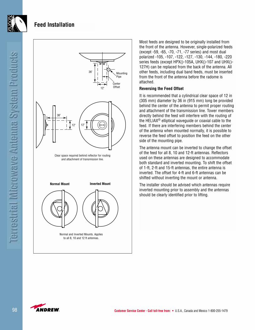
Customer Service Center - Call toll-free from: • U.S.A., Canada and Mexico 1-800-255-147998
Most feeds are designed to be originally installed from the front of the antenna. However, single-polarized feeds(except -59, -65, -70, -71, -77 series) and most dualpolarized -105, -107, -122, -127, -130, -144, -180, -220series feeds (except HPX()-105A, UHX()-107 and UHX()-127H) can be replaced from the back of the antenna. Allother feeds, including dual band feeds, must be insertedfrom the front of the antenna before the radome isattached.
Reversing the Feed Offset
It is recommended that a cylindrical clear space of 12 in(305 mm) diameter by 36 in (915 mm) long be providedbehind the center of the antenna to permit proper routingand attachment of the transmission line. Tower membersdirectly behind the feed will interfere with the routing ofthe HELIAX® elliptical waveguide or coaxial cable to thefeed. If there are interfering members behind the center of the antenna when mounted normally, it is possible toreverse the feed offset to position the feed on the otherside of the mounting pipe.
The antenna mount can be inverted to change the offset of the feed for all 8, 10 and 12-ft antennas. Reflectorsused on these antennas are designed to accommodateboth standard and inverted mounting. To shift the offset of 1-ft, 2-ft and 15-ft antennas, the entire antenna isinverted. The offset for 4-ft and 6-ft antennas can be shifted without inverting the mount or antenna.
The installer should be advised which antennas requireinverted mounting prior to assembly and the antennasshould be clearly identified prior to lifting.
MountingPipe
Normal Mount Inverted Mount
12"
Clear space required behind reflector for routingand attachment of transmission line.
Normal and Inverted Mounts. Appliesto all 8, 10 and 12 ft antennas.
Center Offset
36"
12"12"
36"
Feed Installation
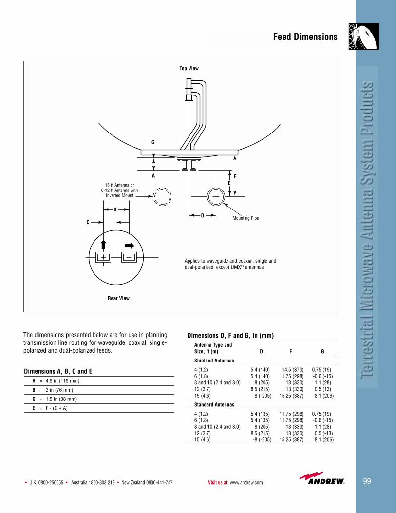
• U.K. 0800-250055 • Australia 1800-803 219 • New Zealand 0800-441-747 Visit us at: www.andrew.com 99
The dimensions presented below are for use in planningtransmission line routing for waveguide, coaxial, single-polarized and dual-polarized feeds.
Dimensions D, F and G, in (mm)Antenna Type and Size, ft (m) D F G
Shielded Antennas
4 (1.2) 5.4 (140) 14.5 (370) 0.75 (19)6 (1.8) 5.4 (140) 11.75 (298) -0.6 (-15)8 and 10 (2.4 and 3.0) 8 (205) 13 (330) 1.1 (28)12 (3.7) 8.5 (215) 13 (330) 0.5 (13)15 (4.6) - 8 (-205) 15.25 (387) 8.1 (206)
Standard Antennas
4 (1.2) 5.4 (135) 11.75 (298) 0.75 (19)6 (1.8) 5.4 (135) 11.75 (298) -0.6 (-15)8 and 10 (2.4 and 3.0) 8 (205) 13 (330) 1.1 (28)12 (3.7) 8.5 (215) 13 (330) 0.5 (-13)15 (4.6) -8 (-205) 15.25 (387) 8.1 (206)
15 ft Antenna or6-12 ft Antenna with
Inverted Mount
Mounting Pipe
Top View
BD
EF
G
A
Applies to waveguide and coaxial, single and dual-polarized, except UMX® antennas
C
Dimensions A, B, C and EA = 4.5 in (115 mm)
B = 3 in (76 mm)
C = 1.5 in (38 mm)
E = F - (G + A)
Rear View
Feed Dimensions
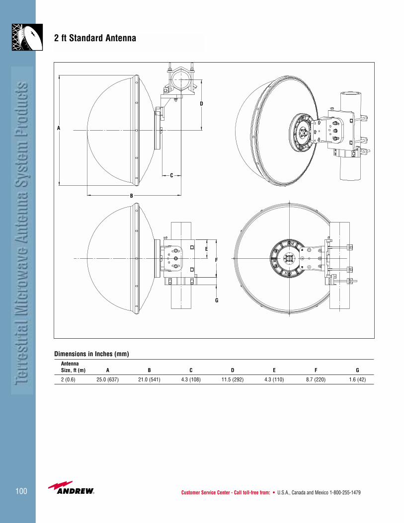
Customer Service Center - Call toll-free from: • U.S.A., Canada and Mexico 1-800-255-1479100
Dimensions in Inches (mm)Antenna Size, ft (m) A B C D E F G
2 (0.6) 25.0 (637) 21.0 (541) 4.3 (108) 11.5 (292) 4.3 (110) 8.7 (220) 1.6 (42)
2 ft Standard Antenna
D
C
B
A
E
F
G
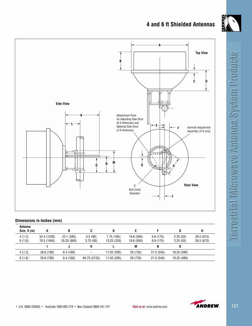
• U.K. 0800-250055 • Australia 1800-803 219 • New Zealand 0800-441-747 Visit us at: www.andrew.com 101
A
B
C D
EF
G H
IBolt CircleDiameter
J
K
L
MNO
Top View
Rear View
Side View
Attachment Pointfor Adjusting Side Strut (6 ft Antennas) andOptional Side Strut (4 ft Antennas)
Azimuth AdjustmentAssembly (4 ft only)
Dimensions in Inches (mm)Antenna Size, ft (m) A B C D E F G H
4 (1.2) 52.4 (1330) 23.1 (585) 3.5 (90) 7.75 (195) 19.6 (500) 6.9 (175) 2.25 (55) 26.5 (675)6 (1.8) 76.5 (1945) 35.25 (895) 3.75 (95) 13.25 (335) 19.6 (500) 6.9 (175) 2.25 (55) 26.5 (675)
I J K L M N O
4 (1.2) 30.6 (780) 6.4 (160) – 11.62 (295) 29 (735) 21.5 (545) 19.25 (490)
6 (1.8) 30.6 (780) 6.4 (160) 84.75 (2155) 11.62 (295) 29 (735) 21.5 (545) 19.25 (490)
4 and 6 ft Shielded Antennas
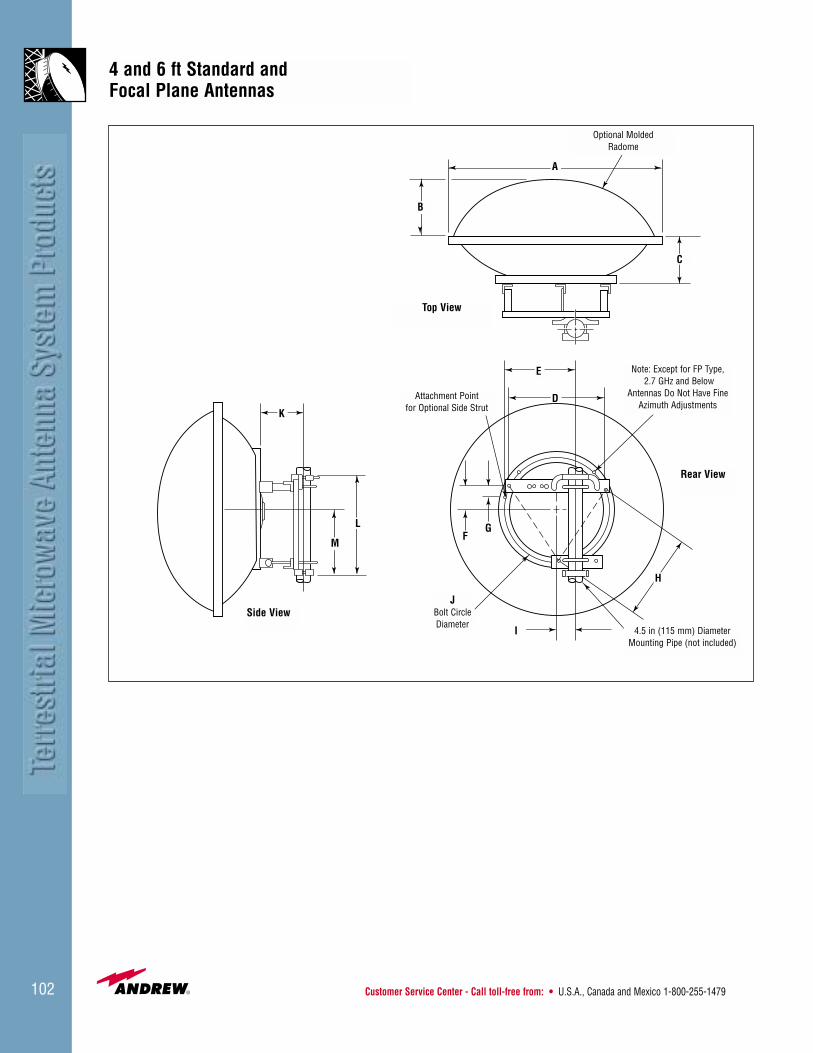
Customer Service Center - Call toll-free from: • U.S.A., Canada and Mexico 1-800-255-1479102
Optional MoldedRadome
Note: Except for FP Type,2.7 GHz and Below
Antennas Do Not Have FineAzimuth Adjustments
Attachment Pointfor Optional Side Strut
4.5 in (115 mm) DiameterMounting Pipe (not included)
Side View
Top View
A
B
C
D
E
FG
H
I
JBolt CircleDiameter
K
L
M
4 and 6 ft Standard and Focal Plane Antennas
Rear View
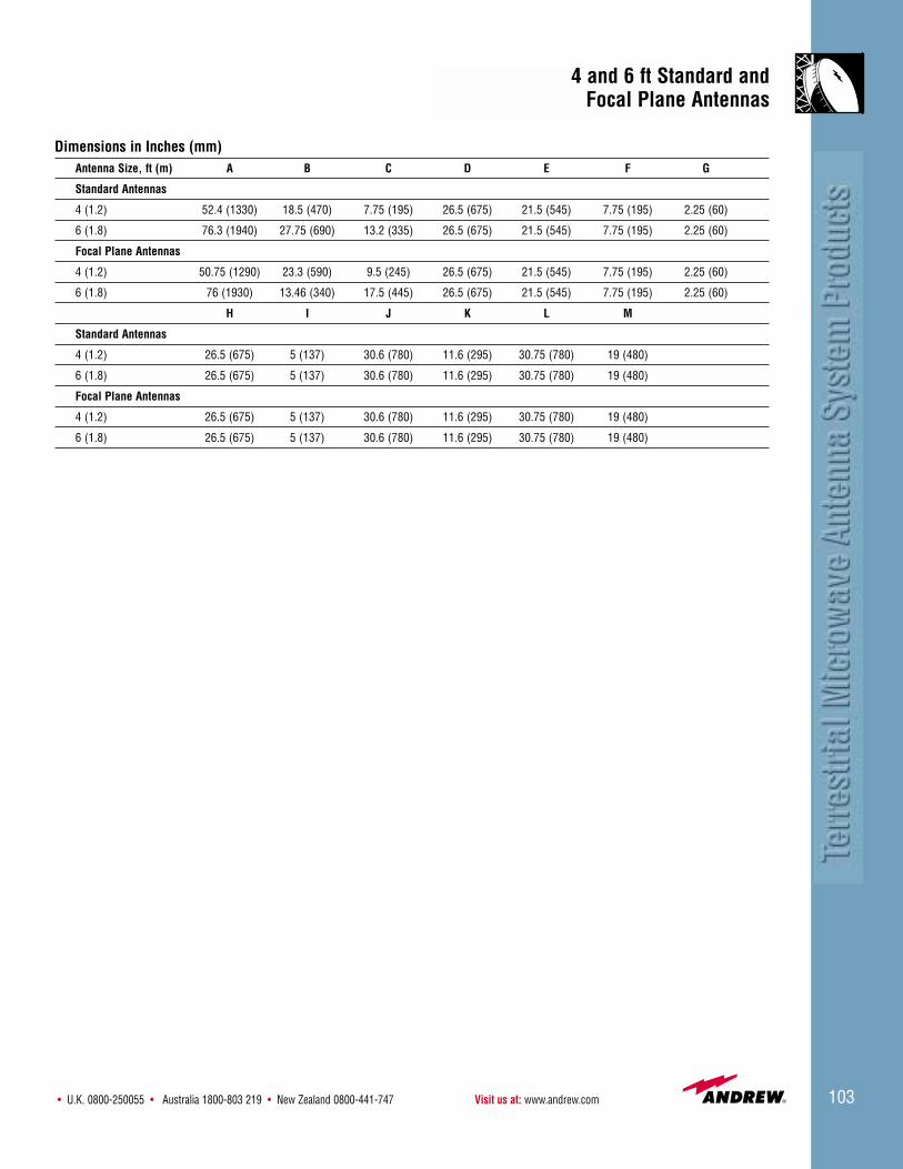
• U.K. 0800-250055 • Australia 1800-803 219 • New Zealand 0800-441-747 Visit us at: www.andrew.com 103
Dimensions in Inches (mm)Antenna Size, ft (m) A B C D E F G
Standard Antennas
4 (1.2) 52.4 (1330) 18.5 (470) 7.75 (195) 26.5 (675) 21.5 (545) 7.75 (195) 2.25 (60)
6 (1.8) 76.3 (1940) 27.75 (690) 13.2 (335) 26.5 (675) 21.5 (545) 7.75 (195) 2.25 (60)
Focal Plane Antennas
4 (1.2) 50.75 (1290) 23.3 (590) 9.5 (245) 26.5 (675) 21.5 (545) 7.75 (195) 2.25 (60)
6 (1.8) 76 (1930) 13.46 (340) 17.5 (445) 26.5 (675) 21.5 (545) 7.75 (195) 2.25 (60)
H I J K L M
Standard Antennas
4 (1.2) 26.5 (675) 5 (137) 30.6 (780) 11.6 (295) 30.75 (780) 19 (480)
6 (1.8) 26.5 (675) 5 (137) 30.6 (780) 11.6 (295) 30.75 (780) 19 (480)
Focal Plane Antennas
4 (1.2) 26.5 (675) 5 (137) 30.6 (780) 11.6 (295) 30.75 (780) 19 (480)
6 (1.8) 26.5 (675) 5 (137) 30.6 (780) 11.6 (295) 30.75 (780) 19 (480)
4 and 6 ft Standard and Focal Plane Antennas
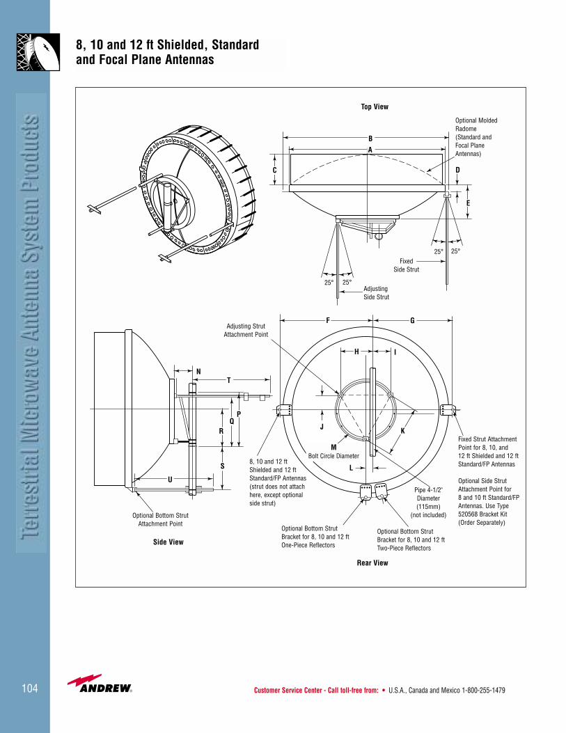
Customer Service Center - Call toll-free from: • U.S.A., Canada and Mexico 1-800-255-1479104
AdjustingSide Strut
Optional MoldedRadome(Standard andFocal PlaneAntennas)
FixedSide Strut
Pipe 4-1/2"Diameter(115mm)
(not included)
Fixed Strut AttachmentPoint for 8, 10, and 12 ft Shielded and 12 ft Standard/FP Antennas
Optional Side StrutAttachment Point for 8 and 10 ft Standard/FPAntennas. Use Type520568 Bracket Kit (Order Separately)
Optional Bottom Strut Bracket for 8, 10 and 12 ft Two-Piece Reflectors
Optional Bottom Strut Bracket for 8, 10 and 12 ft One-Piece Reflectors
Adjusting StrutAttachment Point
8, 10 and 12 ftShielded and 12 ftStandard/FP Antennas(strut does not attachhere, except optionalside strut)
Optional Bottom StrutAttachment Point
Rear View
Side View
Top View
AB
C D
E
F G
H I
J K
L
MBolt Circle Diameter
N
PQ
R
S
T
25°
U
8, 10 and 12 ft Shielded, Standard and Focal Plane Antennas
25°
25°25°
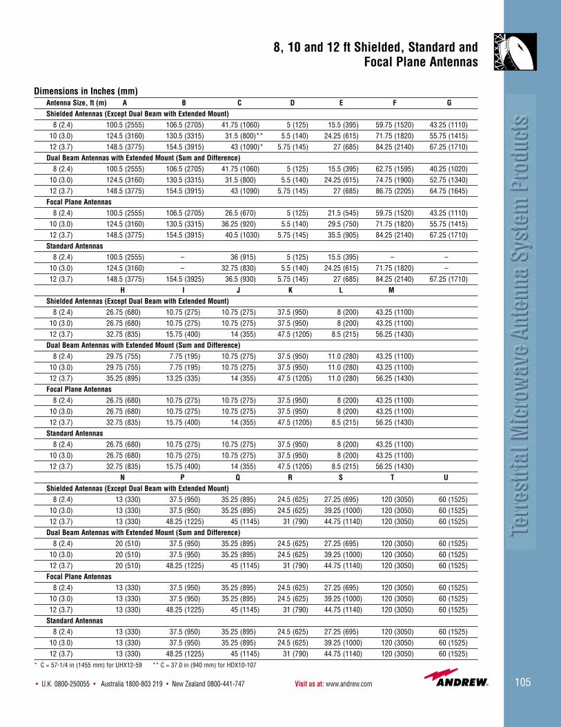
• U.K. 0800-250055 • Australia 1800-803 219 • New Zealand 0800-441-747 Visit us at: www.andrew.com 105
Dimensions in Inches (mm)Antenna Size, ft (m) A B C D E F GShielded Antennas (Except Dual Beam with Extended Mount)
8 (2.4) 100.5 (2555) 106.5 (2705) 41.75 (1060) 5 (125) 15.5 (395) 59.75 (1520) 43.25 (1110)10 (3.0) 124.5 (3160) 130.5 (3315) 31.5 (800)** 5.5 (140) 24.25 (615) 71.75 (1820) 55.75 (1415)12 (3.7) 148.5 (3775) 154.5 (3915) 43 (1090)* 5.75 (145) 27 (685) 84.25 (2140) 67.25 (1710)
Dual Beam Antennas with Extended Mount (Sum and Difference)8 (2.4) 100.5 (2555) 106.5 (2705) 41.75 (1060) 5 (125) 15.5 (395) 62.75 (1595) 40.25 (1020)
10 (3.0) 124.5 (3160) 130.5 (3315) 31.5 (800) 5.5 (140) 24.25 (615) 74.75 (1900) 52.75 (1340)12 (3.7) 148.5 (3775) 154.5 (3915) 43 (1090) 5.75 (145) 27 (685) 86.75 (2205) 64.75 (1645)
Focal Plane Antennas8 (2.4) 100.5 (2555) 106.5 (2705) 26.5 (670) 5 (125) 21.5 (545) 59.75 (1520) 43.25 (1110)
10 (3.0) 124.5 (3160) 130.5 (3315) 36.25 (920) 5.5 (140) 29.5 (750) 71.75 (1820) 55.75 (1415)12 (3.7) 148.5 (3775) 154.5 (3915) 40.5 (1030) 5.75 (145) 35.5 (905) 84.25 (2140) 67.25 (1710)
Standard Antennas8 (2.4) 100.5 (2555) – 36 (915) 5 (125) 15.5 (395) – –
10 (3.0) 124.5 (3160) – 32.75 (830) 5.5 (140) 24.25 (615) 71.75 (1820) –12 (3.7) 148.5 (3775) 154.5 (3925) 36.5 (930) 5.75 (145) 27 (685) 84.25 (2140) 67.25 (1710)
H I J K L MShielded Antennas (Except Dual Beam with Extended Mount)
8 (2.4) 26.75 (680) 10.75 (275) 10.75 (275) 37.5 (950) 8 (200) 43.25 (1100)10 (3.0) 26.75 (680) 10.75 (275) 10.75 (275) 37.5 (950) 8 (200) 43.25 (1100)12 (3.7) 32.75 (835) 15.75 (400) 14 (355) 47.5 (1205) 8.5 (215) 56.25 (1430)
Dual Beam Antennas with Extended Mount (Sum and Difference)8 (2.4) 29.75 (755) 7.75 (195) 10.75 (275) 37.5 (950) 11.0 (280) 43.25 (1100)
10 (3.0) 29.75 (755) 7.75 (195) 10.75 (275) 37.5 (950) 11.0 (280) 43.25 (1100)12 (3.7) 35.25 (895) 13.25 (335) 14 (355) 47.5 (1205) 11.0 (280) 56.25 (1430)
Focal Plane Antennas8 (2.4) 26.75 (680) 10.75 (275) 10.75 (275) 37.5 (950) 8 (200) 43.25 (1100)
10 (3.0) 26.75 (680) 10.75 (275) 10.75 (275) 37.5 (950) 8 (200) 43.25 (1100)12 (3.7) 32.75 (835) 15.75 (400) 14 (355) 47.5 (1205) 8.5 (215) 56.25 (1430)
Standard Antennas8 (2.4) 26.75 (680) 10.75 (275) 10.75 (275) 37.5 (950) 8 (200) 43.25 (1100)
10 (3.0) 26.75 (680) 10.75 (275) 10.75 (275) 37.5 (950) 8 (200) 43.25 (1100)12 (3.7) 32.75 (835) 15.75 (400) 14 (355) 47.5 (1205) 8.5 (215) 56.25 (1430)
N P Q R S T UShielded Antennas (Except Dual Beam with Extended Mount)
8 (2.4) 13 (330) 37.5 (950) 35.25 (895) 24.5 (625) 27.25 (695) 120 (3050) 60 (1525)10 (3.0) 13 (330) 37.5 (950) 35.25 (895) 24.5 (625) 39.25 (1000) 120 (3050) 60 (1525)12 (3.7) 13 (330) 48.25 (1225) 45 (1145) 31 (790) 44.75 (1140) 120 (3050) 60 (1525)
Dual Beam Antennas with Extended Mount (Sum and Difference)8 (2.4) 20 (510) 37.5 (950) 35.25 (895) 24.5 (625) 27.25 (695) 120 (3050) 60 (1525)
10 (3.0) 20 (510) 37.5 (950) 35.25 (895) 24.5 (625) 39.25 (1000) 120 (3050) 60 (1525)12 (3.7) 20 (510) 48.25 (1225) 45 (1145) 31 (790) 44.75 (1140) 120 (3050) 60 (1525)
Focal Plane Antennas8 (2.4) 13 (330) 37.5 (950) 35.25 (895) 24.5 (625) 27.25 (695) 120 (3050) 60 (1525)
10 (3.0) 13 (330) 37.5 (950) 35.25 (895) 24.5 (625) 39.25 (1000) 120 (3050) 60 (1525)12 (3.7) 13 (330) 48.25 (1225) 45 (1145) 31 (790) 44.75 (1140) 120 (3050) 60 (1525)
Standard Antennas8 (2.4) 13 (330) 37.5 (950) 35.25 (895) 24.5 (625) 27.25 (695) 120 (3050) 60 (1525)
10 (3.0) 13 (330) 37.5 (950) 35.25 (895) 24.5 (625) 39.25 (1000) 120 (3050) 60 (1525)12 (3.7) 13 (330) 48.25 (1225) 45 (1145) 31 (790) 44.75 (1140) 120 (3050) 60 (1525)
* C = 57-1/4 in (1455 mm) for UHX12-59 ** C = 37.0 in (940 mm) for HDX10-107
8, 10 and 12 ft Shielded, Standard and Focal Plane Antennas
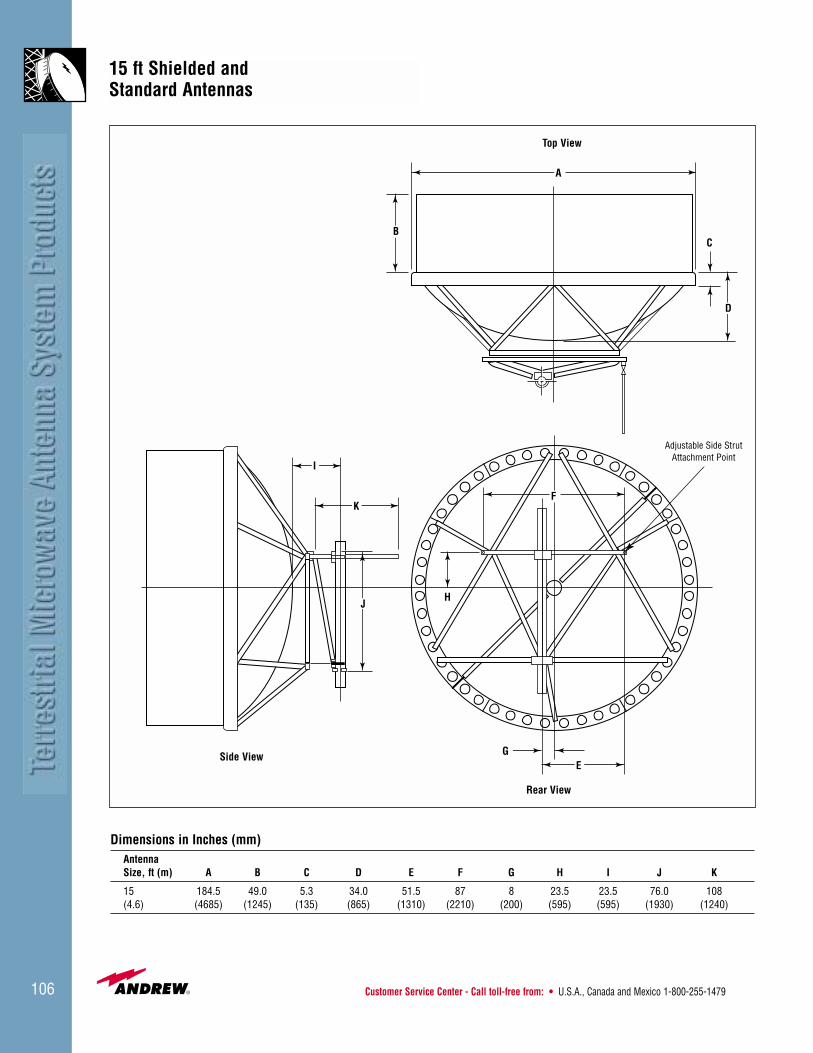
Customer Service Center - Call toll-free from: • U.S.A., Canada and Mexico 1-800-255-1479106
Adjustable Side StrutAttachment Point
A
BC
E
F
G
H
I
J
K
Side View
Rear View
Top View
Dimensions in Inches (mm)AntennaSize, ft (m) A B C D E F G H I J K
15 184.5 49.0 5.3 34.0 51.5 87 8 23.5 23.5 76.0 108(4.6) (4685) (1245) (135) (865) (1310) (2210) (200) (595) (595) (1930) (1240)
15 ft Shielded and Standard Antennas
D
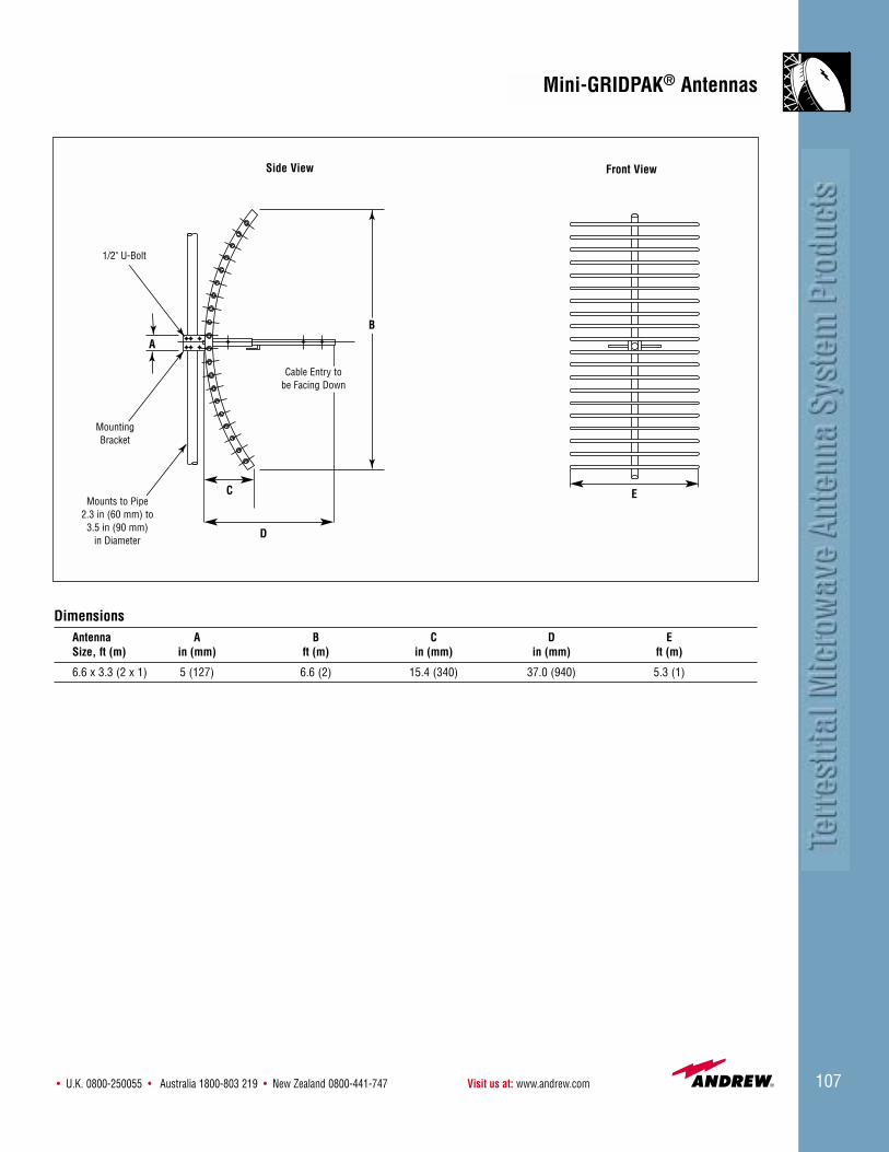
• U.K. 0800-250055 • Australia 1800-803 219 • New Zealand 0800-441-747 Visit us at: www.andrew.com 107
Mounts to Pipe 2.3 in (60 mm) to
3.5 in (90 mm) in Diameter
MountingBracket
1/2" U-Bolt
Mini-GRIDPAK® Antennas
Side View Front View
DimensionsAntenna A B C D ESize, ft (m) in (mm) ft (m) in (mm) in (mm) ft (m)
6.6 x 3.3 (2 x 1) 5 (127) 6.6 (2) 15.4 (340) 37.0 (940) 5.3 (1)
Cable Entry tobe Facing Down
A
C
B
D
E
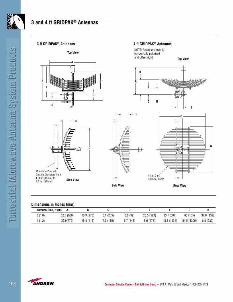
Customer Service Center - Call toll-free from: • U.S.A., Canada and Mexico 1-800-255-1479108
NOTE: Antenna shown ishorizontally polarizedand offset right Top View
Rear ViewSide View
4 ft (1.3 m)Diameter Circle
Mounts to Pipe withOutside Diameters from1.88 in (48mm) to 4.5 in (115mm) Side View
Top View
3 ft GRIDPAK® Antennas 4 ft GRIDPAK® Antennas
3 and 4 ft GRIDPAK® Antennas
A
B
C
D
E
F A
B
C D
E
G
H
HF
G
Dimensions in Inches (mm)Antenna Size, ft (m) A B C D E F G H
3 (1.0) 32.3 (950) 10.9 (278) 8.1 (205) 3.6 (92) 20.5 (520) 23.1 (587) 65 (165) 37.8 (959)
4 (1.2) 29.9(772) 16.4 (416) 7.3 (185) 5.7 (146) 6.9 (175) 48.5 (1231) 51.5 (1309) 8.3 (232)

• U.K. 0800-250055 • Australia 1800-803 219 • New Zealand 0800-441-747 Visit us at: www.andrew.com 109
6 ft GRIDPAK® Antennas
E
C
A
B
D
Dimensions in Inches (mm)Antenna Size, ft (m) A B C D E
6 (2.0) 41.3 (1049) 46.0 (1172) 8.0 (200) 81.0 (2061) 12.0 (304)
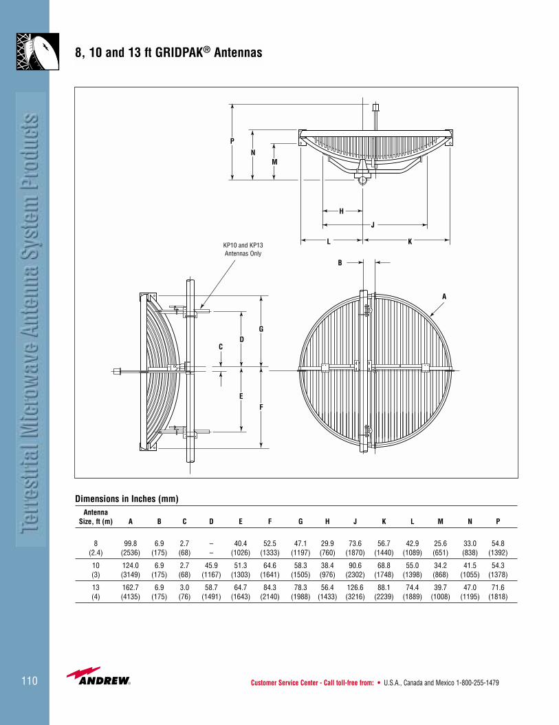
Customer Service Center - Call toll-free from: • U.S.A., Canada and Mexico 1-800-255-1479110
����
A
B
CD
EF
G
H
J
KL
MN
P
KP10 and KP13Antennas Only
Dimensions in Inches (mm)Antenna
Size, ft (m) A B C D E F G H J K L M N P
8 99.8 6.9 2.7 – 40.4 52.5 47.1 29.9 73.6 56.7 42.9 25.6 33.0 54.8(2.4) (2536) (175) (68) – (1026) (1333) (1197) (760) (1870) (1440) (1089) (651) (838) (1392)
10 124.0 6.9 2.7 45.9 51.3 64.6 58.3 38.4 90.6 68.8 55.0 34.2 41.5 54.3(3) (3149) (175) (68) (1167) (1303) (1641) (1505) (976) (2302) (1748) (1398) (868) (1055) (1378)
13 162.7 6.9 3.0 58.7 64.7 84.3 78.3 56.4 126.6 88.1 74.4 39.7 47.0 71.6(4) (4135) (175) (76) (1491) (1643) (2140) (1988) (1433) (3216) (2239) (1889) (1008) (1195) (1818)
8, 10 and 13 ft GRIDPAK® Antennas
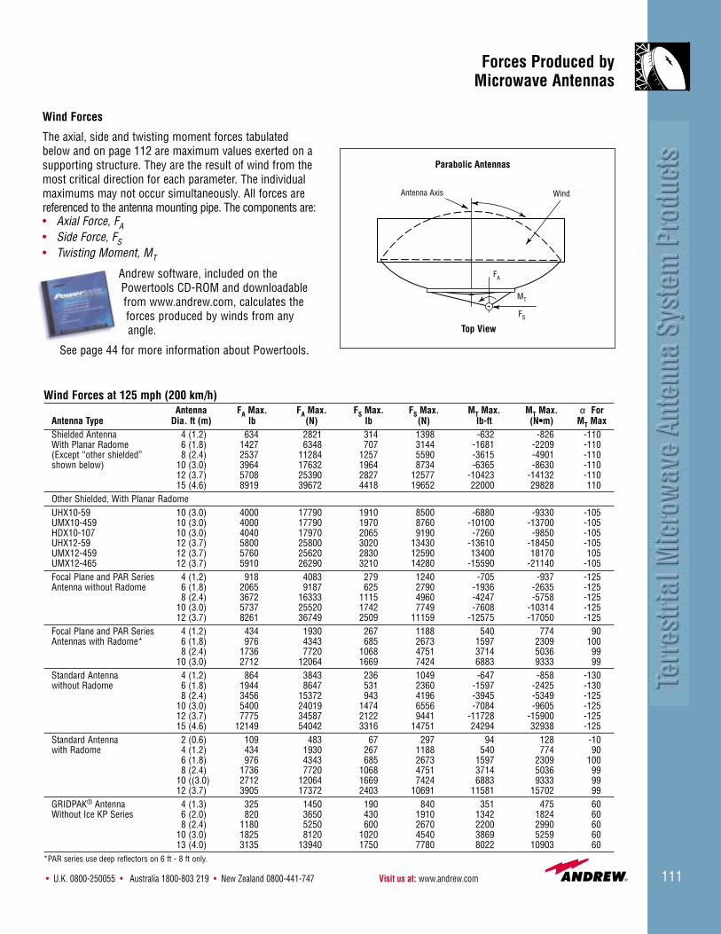
• U.K. 0800-250055 • Australia 1800-803 219 • New Zealand 0800-441-747 Visit us at: www.andrew.com 111
Wind Forces
The axial, side and twisting moment forces tabulatedbelow and on page 112 are maximum values exerted on asupporting structure. They are the result of wind from themost critical direction for each parameter. The individualmaximums may not occur simultaneously. All forces arereferenced to the antenna mounting pipe. The components are:• Axial Force, FA• Side Force, FS• Twisting Moment, MT
Andrew software, included on thePowertools CD-ROM and downloadablefrom www.andrew.com, calculates theforces produced by winds from anyangle.
See page 44 for more information about Powertools.
Antenna Axis Wind
Top View
Parabolic Antennas
FA
MT
FS
Wind Forces at 125 mph (200 km/h)Antenna FA Max. FA Max. FS Max. FS Max. MT Max. MT Max. α For
Antenna Type Dia. ft (m) lb (N) lb (N) lb-ft (N•m) MT MaxShielded Antenna 4 (1.2) 634 2821 314 1398 -632 -826 -110With Planar Radome 6 (1.8) 1427 6348 707 3144 -1681 -2209 -110(Except “other shielded” 8 (2.4) 2537 11284 1257 5590 -3615 -4901 -110shown below) 10 (3.0) 3964 17632 1964 8734 -6365 -8630 -110
12 (3.7) 5708 25390 2827 12577 -10423 -14132 -11015 (4.6) 8919 39672 4418 19652 22000 29828 110
Other Shielded, With Planar RadomeUHX10-59 10 (3.0) 4000 17790 1910 8500 -6880 -9330 -105UMX10-459 10 (3.0) 4000 17790 1970 8760 -10100 -13700 -105HDX10-107 10 (3.0) 4040 17970 2065 9190 -7260 -9850 -105UHX12-59 12 (3.7) 5800 25800 3020 13430 -13610 -18450 -105UMX12-459 12 (3.7) 5760 25620 2830 12590 13400 18170 105UMX12-465 12 (3.7) 5910 26290 3210 14280 -15590 -21140 -105Focal Plane and PAR Series 4 (1.2) 918 4083 279 1240 -705 -937 -125Antenna without Radome 6 (1.8) 2065 9187 625 2790 -1936 -2635 -125
8 (2.4) 3672 16333 1115 4960 -4247 -5758 -12510 (3.0) 5737 25520 1742 7749 -7608 -10314 -12512 (3.7) 8261 36749 2509 11159 -12575 -17050 -125
Focal Plane and PAR Series 4 (1.2) 434 1930 267 1188 540 774 90Antennas with Radome* 6 (1.8) 976 4343 685 2673 1597 2309 100
8 (2.4) 1736 7720 1068 4751 3714 5036 9910 (3.0) 2712 12064 1669 7424 6883 9333 99
Standard Antenna 4 (1.2) 864 3843 236 1049 -647 -858 -130without Radome 6 (1.8) 1944 8647 531 2360 -1597 -2425 -130
8 (2.4) 3456 15372 943 4196 -3945 -5349 -12510 (3.0) 5400 24019 1474 6556 -7084 -9605 -12512 (3.7) 7775 34587 2122 9441 -11728 -15900 -12515 (4.6) 12149 54042 3316 14751 24294 32938 -125
Standard Antenna 2 (0.6) 109 483 67 297 94 128 -10with Radome 4 (1.2) 434 1930 267 1188 540 774 90
6 (1.8) 976 4343 685 2673 1597 2309 1008 (2.4) 1736 7720 1068 4751 3714 5036 99
10 ((3.0) 2712 12064 1669 7424 6883 9333 9912 (3.7) 3905 17372 2403 10691 11581 15702 99
GRIDPAK® Antenna 4 (1.3) 325 1450 190 840 351 475 60Without Ice KP Series 6 (2.0) 820 3650 430 1910 1342 1824 60
8 (2.4) 1180 5250 600 2670 2200 2990 6010 (3.0) 1825 8120 1020 4540 3869 5259 6013 (4.0) 3135 13940 1750 7780 8022 10903 60
*PAR series use deep reflectors on 6 ft - 8 ft only.
Forces Produced by Microwave Antennas
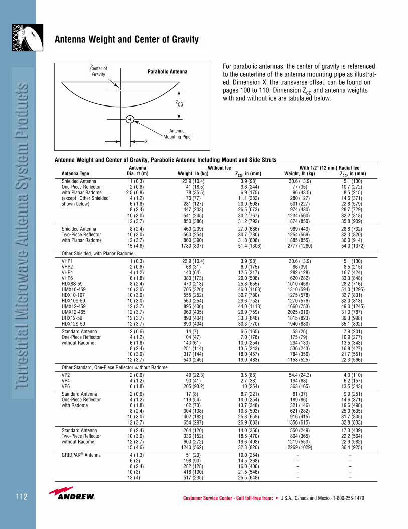
Customer Service Center - Call toll-free from: • U.S.A., Canada and Mexico 1-800-255-1479112
ZCG
X
AntennaMounting Pipe
Center ofGravity Parabolic Antenna
For parabolic antennas, the center of gravity is referencedto the centerline of the antenna mounting pipe as illustrat-ed. Dimension X, the transverse offset, can be found onpages 100 to 110. Dimension ZCG and antenna weightswith and without ice are tabulated below.
Antenna Weight and Center of Gravity, Parabolic Antenna Including Mount and Side StrutsAntenna Without Ice With 1/2" (12 mm) Radial Ice
Antenna Type Dia. ft (m) Weight, lb (kg) ZCG, in (mm) Weight, lb (kg) ZCG, in (mm)Shielded Antenna 1 (0.3) 22.9 (10.4) 3.9 (98) 30.6 (13.9) 5.1 (130)One-Piece Reflector 2 (0.6) 41 (18.5) 9.6 (244) 77 (35) 10.7 (272)with Planar Radome 2.5 (0.8) 78 (35.5) 6.9 (175) 96 (43.5) 8.5 (215)(except “Other Shielded” 4 (1.2) 170 (77) 11.1 (282) 280 (127) 14.6 (371)shown below) 6 (1.8) 281 (127) 20.0 (508) 501 (227) 22.8 (579)
8 (2.4) 447 (203) 26.5 (673) 974 (430) 28.7 (729)10 (3.0) 541 (245) 30.2 (767) 1234 (560) 32.2 (818)12 (3.7) 850 (386) 31.2 (792) 1874 (850) 35.8 (909)
Shielded Antenna 8 (2.4) 460 (209) 27.0 (686) 989 (449) 28.8 (732)Two-Piece Reflector 10 (3.0) 560 (254) 30.7 (780) 1254 (569) 32.3 (820)with Planar Radome 12 (3.7) 860 (390) 31.8 (808) 1885 (855) 36.0 (914)
15 (4.6) 1780 (807) 51.4 (1306) 2777 (1260) 54.0 (1372)Other Shielded, with Planar RadomeVHP1 1 (0.3) 22.9 (10.4) 3.9 (98) 30.6 (13.9) 5.1 (130)VHP2 2 (0.6) 68 (31) 6.9 (175) 86 (39) 8.5 (215)VHP4 4 (1.2) 140 (64) 12.5 (317) 282 (128) 16.7 (424)VHP6 6 (1.8) 380 (173) 20.0 (508) 620 (282) 33.3 (848)HDX8S-59 8 (2.4) 470 (213) 25.8 (655) 1010 (458) 28.2 (716)UMX10-459 10 (3.0) 705 (320) 46.0 (1168) 1310 (594) 51.0 (1295)HDX10-107 10 (3.0) 555 (252) 30.7 (780) 1275 (578) 32.7 (831)HDX10S-59 10 (3.0) 560 (254) 29.6 (752) 1270 (576) 32.0 (813)UMX12-459 12 (3.7) 895 (406) 44.0 (1118) 1660 (753) 49.0 (1245)UMX12-465 12 (3.7) 960 (435) 29.9 (759) 2025 (919) 31.0 (787)UHX12-59 12 (3.7) 890 (404) 33.3 (846) 1815 (823) 39.3 (998)HDX12S-59 12 (3.7) 890 (404) 30.3 (770) 1940 (880) 35.1 (892)Standard Antenna 2 (0.6) 14 (7) 6.5 (165) 58 (26) 7.9 (201)One-Piece Reflector 4 (1.2) 104 (47) 7.0 (178) 175 (79) 10.9 (277)without Radome 6 (1.8) 143 (61) 10.0 (254) 294 (133) 13.5 (343)
8 (2.4) 251 (114) 13.5 (343) 536 (243) 16.8 (427)10 (3.0) 317 (144) 18.0 (457) 784 (356) 21.7 (551)12 (3.7) 540 (245) 19.0 (483) 1158 (525) 22.3 (566)
Other Standard, One-Piece Reflector without RadomeVP2 2 (0.6) 49 (22.3) 3.5 (88) 54.4 (24.3) 4.3 (110)VP4 4 (1.2) 90 (41) 2.7 (38) 194 (88) 6.2 (157)VP6 6 (1.8) 205 (93.2) 10 (254) 363 (165) 13.5 (343)Standard Antenna 2 (0.6) 17 (8) 8.7 (221) 81 (37) 9.9 (251)One-Piece Reflector 4 (1.2) 119 (54) 10.0 (254) 189 (86) 14.6 (371)with Radome 6 (1.8) 162 (73) 13.7 (348) 321 (146) 19.6 (498)
8 (2.4) 304 (138) 19.8 (503) 621 (282) 25.0 (635)10 (3.0) 402 (182) 25.8 (655) 916 (415) 31.7 (805)12 (3.7) 654 (297) 26.9 (683) 1356 (615) 32.8 (833)
Standard Antenna 8 (2.4) 264 (120) 14.0 (356) 550 (249) 17.3 (439)Two-Piece Reflector 10 (3.0) 336 (152) 18.5 (470) 804 (365) 22.2 (564)without Radome 12 (3.7) 600 (272) 19.6 (498) 1219 (553) 22.9 (582)
15 (4.6) 1240 (562) 32.3 (820) 2269 (1029) 36.4 (925)GRIDPAK® Antenna 4 (1.3) 51 (23) 10.0 (254) – –
6 (2) 198 (90) 14.5 (368) – – 8 (2.4) 282 (128) 16.0 (406) – –
10 (3) 418 (190) 21.5 (546) – – 13 (4) 517 (235) 25.5 (648) – –
Antenna Weight and Center of Gravity
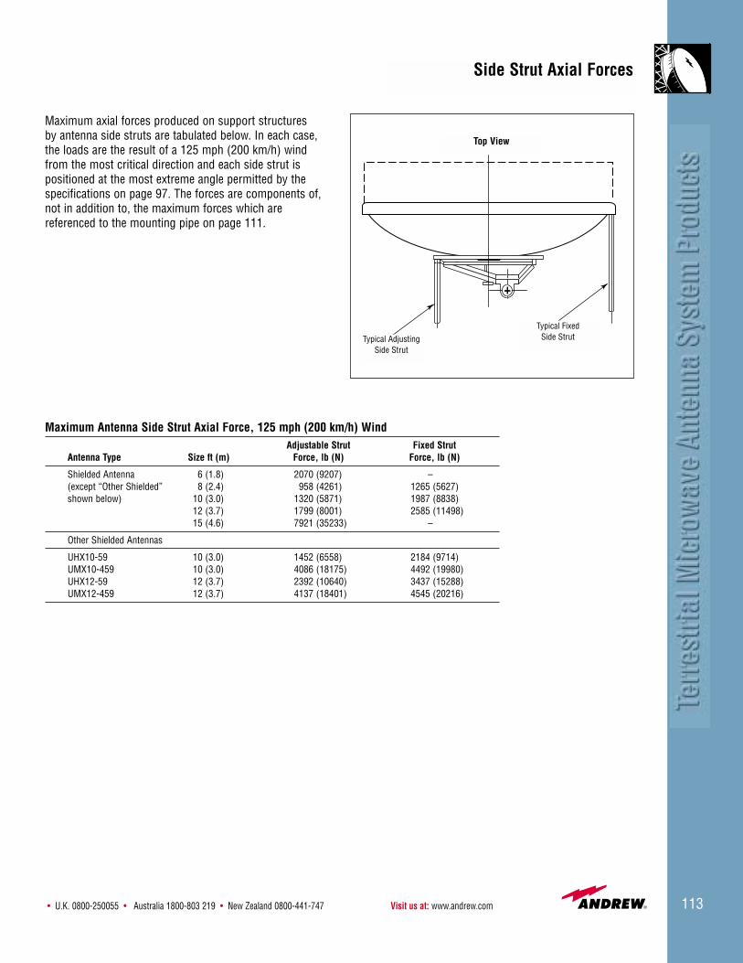
• U.K. 0800-250055 • Australia 1800-803 219 • New Zealand 0800-441-747 Visit us at: www.andrew.com 113
Maximum axial forces produced on support structures by antenna side struts are tabulated below. In each case,the loads are the result of a 125 mph (200 km/h) windfrom the most critical direction and each side strut ispositioned at the most extreme angle permitted by thespecifications on page 97. The forces are components of,not in addition to, the maximum forces which are referenced to the mounting pipe on page 111.
Typical AdjustingSide Strut
Typical FixedSide Strut
Top View
Maximum Antenna Side Strut Axial Force, 125 mph (200 km/h) WindAdjustable Strut Fixed Strut
Antenna Type Size ft (m) Force, lb (N) Force, lb (N)
Shielded Antenna 6 (1.8) 2070 (9207) – (except “Other Shielded” 8 (2.4) 958 (4261) 1265 (5627)shown below) 10 (3.0) 1320 (5871) 1987 (8838)
12 (3.7) 1799 (8001) 2585 (11498)15 (4.6) 7921 (35233) –
Other Shielded Antennas
UHX10-59 10 (3.0) 1452 (6558) 2184 (9714)UMX10-459 10 (3.0) 4086 (18175) 4492 (19980)UHX12-59 12 (3.7) 2392 (10640) 3437 (15288)UMX12-459 12 (3.7) 4137 (18401) 4545 (20216)
Side Strut Axial Forces

Customer Service Center - Call toll-free from: • U.S.A., Canada and Mexico 1-800-255-1479114
Antenna Options
UHX10-59 125 mph (200 km/h)
WUHX10-59 155 mph (250 km/h)
SUHX10-59 200 mph (320 km/h)
UHX10-59 Standard paint
EUHX10-59 Corrosive environment paint
WEUHX10-59 High wind and corrosive environment paint
All antenna orders require option codes to specify thedetails for your system. Most antennas include options forselecting feed input types, paint color, radome, packing,and environmental offerings. These option codes areunique characters placed before (prefix) or after (suffix)the base antenna type number. Prefix codes are optional.Suffix codes are required.
Prefix Option CodesThe prefix option codes include special environmentaloptions such as high wind and corrosive environment. For additional information about special environmentantennas, request Bulletin 3522.
High Wind Environment Options
High wind options that exceed the standard 125 mph (200 km/h) wind survival rating are available in 155 mph (250 km/h) and 200 mph (320 km/h) survival rating.These heavy duty antenna versions feature strong backstructures for maintaining alignment accuracy in adverseand severe wind conditions.
Use the “W” prefix for 155 mph (250 km/h), and the “S”prefix for 200 mph (320 km/h) survival ratings.
Corrosive Environment Options
The corrosive environment option is available for mostantennas. This option provides long term protection inmarine or salt and most industrial environments includingchemical and fossil fuel areas. A special epoxy paintapplied at the factory provides added protection. In addition, corrosion inhibiting compounds and protectivesealants are applied during installation.
Note: High wind and corrosive environment prefix codesare optional.
Suffix Option CodesSuffix option codes are required for your antenna order.The suffix option code is made up of three characters. The first character indicates the feed input type, the sec-ond character indicates the antenna color and applicableradome information, and the third character indicates thepacking options.
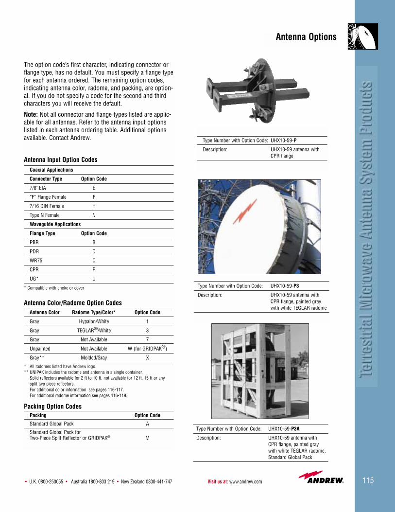
• U.K. 0800-250055 • Australia 1800-803 219 • New Zealand 0800-441-747 Visit us at: www.andrew.com 115
Antenna Options
The option code’s first character, indicating connector orflange type, has no default. You must specify a flange typefor each antenna ordered. The remaining option codes,indicating antenna color, radome, and packing, are option-al. If you do not specify a code for the second and thirdcharacters you will receive the default.
Note: Not all connector and flange types listed are applic-able for all antennas. Refer to the antenna input optionslisted in each antenna ordering table. Additional optionsavailable. Contact Andrew.
Antenna Input Option CodesCoaxial Applications
Connector Type Option Code
7/8" EIA E
“F” Flange Female F
7/16 DIN Female H
Type N Female N
Waveguide Applications
Flange Type Option Code
PBR B
PDR D
WR75 C
CPR P
UG* U
* Compatible with choke or cover
Antenna Color/Radome Option CodesAntenna Color Radome Type/Color* Option Code
Gray Hypalon/White 1
Gray TEGLAR®/White 3
Gray Not Available 7
Unpainted Not Available W (for GRIDPAK®)
Gray** Molded/Gray X
* All radomes listed have Andrew logo.** UNIPAK includes the radome and antenna in a single container.
Solid reflectors available for 2 ft to 10 ft, not available for 12 ft, 15 ft or any split two piece reflectors.For additional color information see pages 116-117.For additional radome information see pages 116-119.
Packing Option CodesPacking Option Code
Standard Global Pack A
Standard Global Pack for Two-Piece Split Reflector or GRIDPAK® M
Type Number with Option Code: UHX10-59-P
Description: UHX10-59 antenna with CPR flange
Type Number with Option Code: UHX10-59-P3
Description: UHX10-59 antenna with CPR flange, painted gray with white TEGLAR radome
Type Number with Option Code: UHX10-59-P3A
Description: UHX10-59 antenna with CPR flange, painted gray with white TEGLAR radome, Standard Global Pack
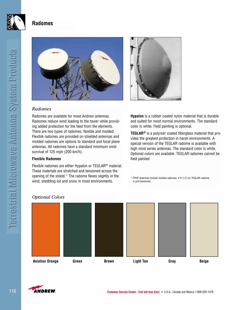
Customer Service Center - Call toll-free from: • U.S.A., Canada and Mexico 1-800-255-1479116
Radomes
Aviation Orange Green Brown Light Tan Gray Beige
Radomes
Radomes are available for most Andrew antennas.Radomes reduce wind loading to the tower while provid-ing added protection for the feed from the elements.There are two types of radomes, flexible and molded.Flexible radomes are provided on shielded antennas andmolded radomes are options to standard and focal planeantennas. All radomes have a standard minimum windsurvival of 125 mph (200 km/h).
Flexible Radomes
Flexible radomes are either Hypalon or TEGLAR® material.These materials are stretched and tensioned across theopening of the shield.* The radome flexes slightly in thewind, shedding ice and snow in most environments.
Hypalon is a rubber coated nylon material that is durableand suited for most normal environments. The standardcolor is white. Field painting is optional.
TEGLAR® is a polymer coated fiberglass material that pro-vides the greatest protection in harsh environments. Aspecial version of the TEGLAR radome is available withhigh wind series antennas. The standard color is white.Optional colors are available. TEGLAR radomes cannot befield painted.
* FPHP antennas include molded radomes. 4 ft (1.2 m) TEGLAR radomeis pre-tensioned.
Optional Colors
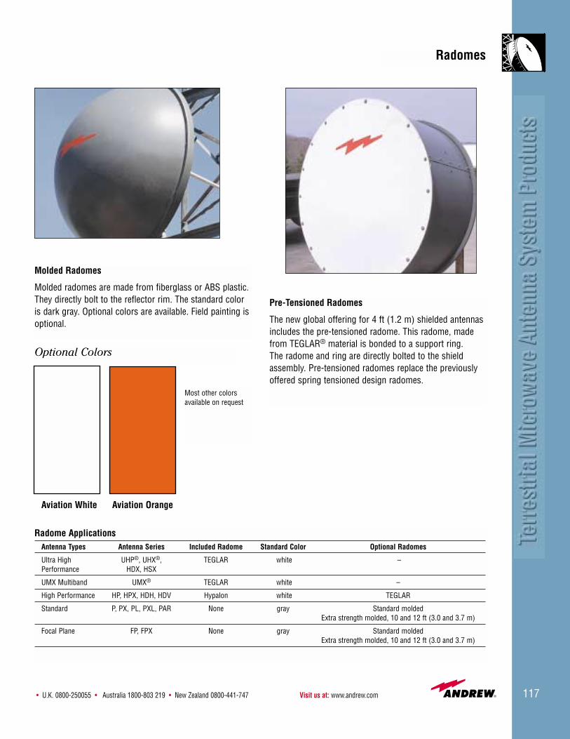
• U.K. 0800-250055 • Australia 1800-803 219 • New Zealand 0800-441-747 Visit us at: www.andrew.com 117
Radomes
Molded Radomes
Molded radomes are made from fiberglass or ABS plastic.They directly bolt to the reflector rim. The standard coloris dark gray. Optional colors are available. Field painting isoptional.
Pre-Tensioned Radomes
The new global offering for 4 ft (1.2 m) shielded antennasincludes the pre-tensioned radome. This radome, madefrom TEGLAR® material is bonded to a support ring. The radome and ring are directly bolted to the shieldassembly. Pre-tensioned radomes replace the previouslyoffered spring tensioned design radomes.
Radome ApplicationsAntenna Types Antenna Series Included Radome Standard Color Optional Radomes
Ultra High UHP®, UHX®, TEGLAR white –Performance HDX, HSX
UMX Multiband UMX® TEGLAR white –
High Performance HP, HPX, HDH, HDV Hypalon white TEGLAR
Standard P, PX, PL, PXL, PAR None gray Standard moldedExtra strength molded, 10 and 12 ft (3.0 and 3.7 m)
Focal Plane FP, FPX None gray Standard moldedExtra strength molded, 10 and 12 ft (3.0 and 3.7 m)
Aviation White Aviation Orange
Optional Colors
Most other colorsavailable on request
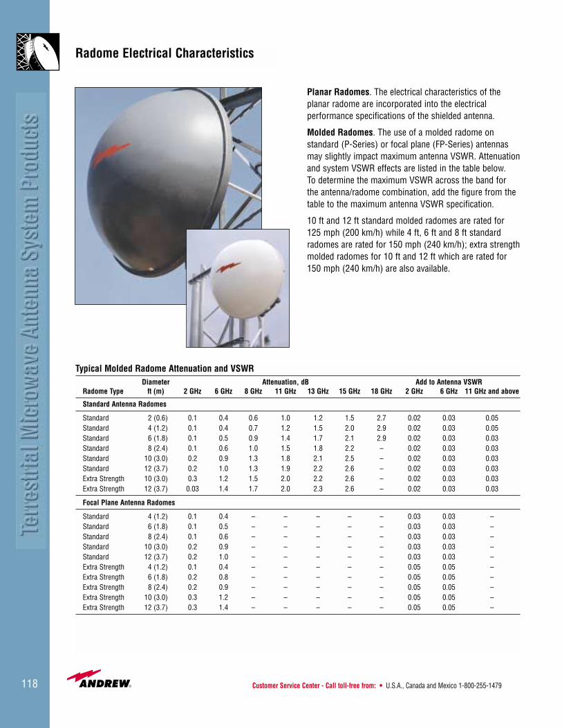
Customer Service Center - Call toll-free from: • U.S.A., Canada and Mexico 1-800-255-1479118
Radome Electrical Characteristics
Planar Radomes. The electrical characteristics of the planar radome are incorporated into the electrical performance specifications of the shielded antenna.
Molded Radomes. The use of a molded radome on standard (P-Series) or focal plane (FP-Series) antennasmay slightly impact maximum antenna VSWR. Attenuationand system VSWR effects are listed in the table below. To determine the maximum VSWR across the band for the antenna/radome combination, add the figure from thetable to the maximum antenna VSWR specification.
10 ft and 12 ft standard molded radomes are rated for 125 mph (200 km/h) while 4 ft, 6 ft and 8 ft standardradomes are rated for 150 mph (240 km/h); extra strengthmolded radomes for 10 ft and 12 ft which are rated for150 mph (240 km/h) are also available.
Typical Molded Radome Attenuation and VSWRDiameter Attenuation, dB Add to Antenna VSWR
Radome Type ft (m) 2 GHz 6 GHz 8 GHz 11 GHz 13 GHz 15 GHz 18 GHz 2 GHz 6 GHz 11 GHz and above
Standard Antenna Radomes
Standard 2 (0.6) 0.1 0.4 0.6 1.0 1.2 1.5 2.7 0.02 0.03 0.05Standard 4 (1.2) 0.1 0.4 0.7 1.2 1.5 2.0 2.9 0.02 0.03 0.05Standard 6 (1.8) 0.1 0.5 0.9 1.4 1.7 2.1 2.9 0.02 0.03 0.03Standard 8 (2.4) 0.1 0.6 1.0 1.5 1.8 2.2 – 0.02 0.03 0.03Standard 10 (3.0) 0.2 0.9 1.3 1.8 2.1 2.5 – 0.02 0.03 0.03Standard 12 (3.7) 0.2 1.0 1.3 1.9 2.2 2.6 – 0.02 0.03 0.03Extra Strength 10 (3.0) 0.3 1.2 1.5 2.0 2.2 2.6 – 0.02 0.03 0.03Extra Strength 12 (3.7) 0.03 1.4 1.7 2.0 2.3 2.6 – 0.02 0.03 0.03
Focal Plane Antenna Radomes
Standard 4 (1.2) 0.1 0.4 – – – – – 0.03 0.03 – Standard 6 (1.8) 0.1 0.5 – – – – – 0.03 0.03 –Standard 8 (2.4) 0.1 0.6 – – – – – 0.03 0.03 – Standard 10 (3.0) 0.2 0.9 – – – – – 0.03 0.03 – Standard 12 (3.7) 0.2 1.0 – – – – – 0.03 0.03 – Extra Strength 4 (1.2) 0.1 0.4 – – – – – 0.05 0.05 – Extra Strength 6 (1.8) 0.2 0.8 – – – – – 0.05 0.05 – Extra Strength 8 (2.4) 0.2 0.9 – – – – – 0.05 0.05 – Extra Strength 10 (3.0) 0.3 1.2 – – – – – 0.05 0.05 – Extra Strength 12 (3.7) 0.3 1.4 – – – – – 0.05 0.05 –

• U.K. 0800-250055 • Australia 1800-803 219 • New Zealand 0800-441-747 Visit us at: www.andrew.com 119
Radome Ordering Information
Current Model Antennas
Shielded antennas. All shielded antennas include aHypalon or TEGLAR® radome. Several antennas (HP andHPX) can be upgraded to TEGLAR for a minimal fee.
Standard and focal plane antennas. Standard and focalplane antennas* do not include a molded radome but inorder to reduce wind loading, one can be added to theantenna crate. The radome can be shipped with the anten-na using the UNIPAK shipping option. Specify the typenumber from the table below.
* FPHP antennas include radome
Older Model Antennas
Radome clip kits. Standard antennas (P-Series) reflectorwith a rolled rim manufactured prior to: September 1987for 4 ft (1.2 m) and 10 ft (3.0 m), February 1991 for 8 ft(2.4 m), and July 1991 for 6 ft (1.8 m) diameters requirethe additional clip kit listed in the table below.
Pre-tensioned radomes. For shielded 4 ft (1.2 m),TEGLAR spring-type attachment radomes have beenreplaced by pre-tensioned TEGLAR radomes that aredirectly attached to the rim of the shield. Field drilling is required. Type Number 520093-9
Standard molded radomes. The 2 ft (0.6 m) standard molded radome has changed in design. For antennasshipped prior to June 1998, request Type Number R2E.
Flexible planar radome replacement kits. These kitsinclude one radome and hardware to replace an existingAndrew planar radome. Specify the type number from thetable below.
Edge protection kit for TEGLAR® radomes. This kit pre-vents damage to the untensioned radome edge between J-bolt anchor points caused by unusually high gustingwinds. Kit includes stainless steel edge protector stripsand attachment hardware. The strips are fastened in pairsto form a band around the edge of the radome. Specifythe type number from the table below.
Radome Ordering InformationReflector Standard Extra Strength Focal Plane Extra Strength Edge ProtectionDiameter ft (m) Molded Molded Molded Focal Plane Molded Clip Kit Hypalon TEGLAR Kit (TEGLAR)
2 (0.6) R2E, VR2, VR2-WH – – – – – 207105*** –
4 (1.2) R4E R4E FR4 FR4-E 207844-1 – 207106** –520093-9*
6 (2.0) R6E R6E FR6 FR6-E 207844-2 520434-1 45665-1 205866-3
8 (2.4) R8F R8F FR8 FR8-E 207844-3 520434-2 45665-2 205866-4
10 (3.0) R10G 39193B FR10 FR10-E 207844-4 520434-3 45665-3 205866-1
12 (3.7) R12F 39194 FR12 FR12-E – 520434-4 45665-4 205866-2
15 (4.6) – – – – – 520434-5 45665-5 205866-5
* Pre-tensioned radome** Spring tensioned radome for older style antennas***Except 2 ft is gray
Revised 9/00

Customer Service Center - Call toll-free from: • U.S.A., Canada and Mexico 1-800-255-1479120
Heavy Duty Export Pack Dual PackStandard Pack
Packing TypeStandard Pack. In most cases, Andrew standard packingis suitable for export. Antennas are shipped as one unit.GRIDPAK® antennas and mounts are shipped in one carton or crate. 4-12 foot (1.2-3.7 m) radomes areshipped in wood crates.
Heavy Duty Export Pack. For your convenience, Andrewalso offers a heavy duty export packing option, whichincludes plywood sheathing of the entire antenna crate.This packing is suitable for ocean, container or air shipment. Multiple packing is also available which will provide considerable savings to the customer.
Dual Pack. Two antennas are packaged together in onecrate, reducing overall shipping volume.
Packing Quantity10-foot (3.0 m) and larger antennas and molded radomesmay require special handling in shipping, depending ondestination and routing. For systems requiring a largenumber of antennas, special packs can be quoted toreduce shipping volume. For example, it is often conve-nient to pack all antennas for the same site in the samebox. Andrew can also provide bulk transport and on-siteassembly of antennas.
For more details about crate dimensions and approximateweights, consult the price list for this catalog.
4 - 6 - 8 ft Standard Radome Pack
4 ft Shielded Antenna Pack
Antenna Packing
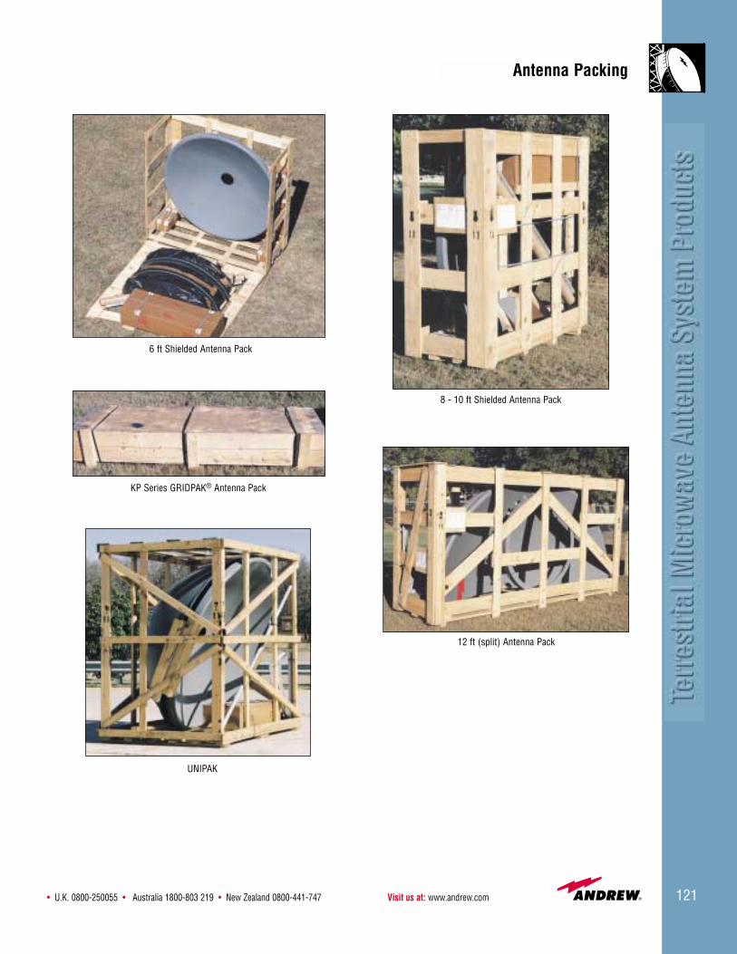
• U.K. 0800-250055 • Australia 1800-803 219 • New Zealand 0800-441-747 Visit us at: www.andrew.com 121
12 ft (split) Antenna Pack
6 ft Shielded Antenna Pack
8 - 10 ft Shielded Antenna Pack
KP Series GRIDPAK® Antenna Pack
Antenna Packing
UNIPAK
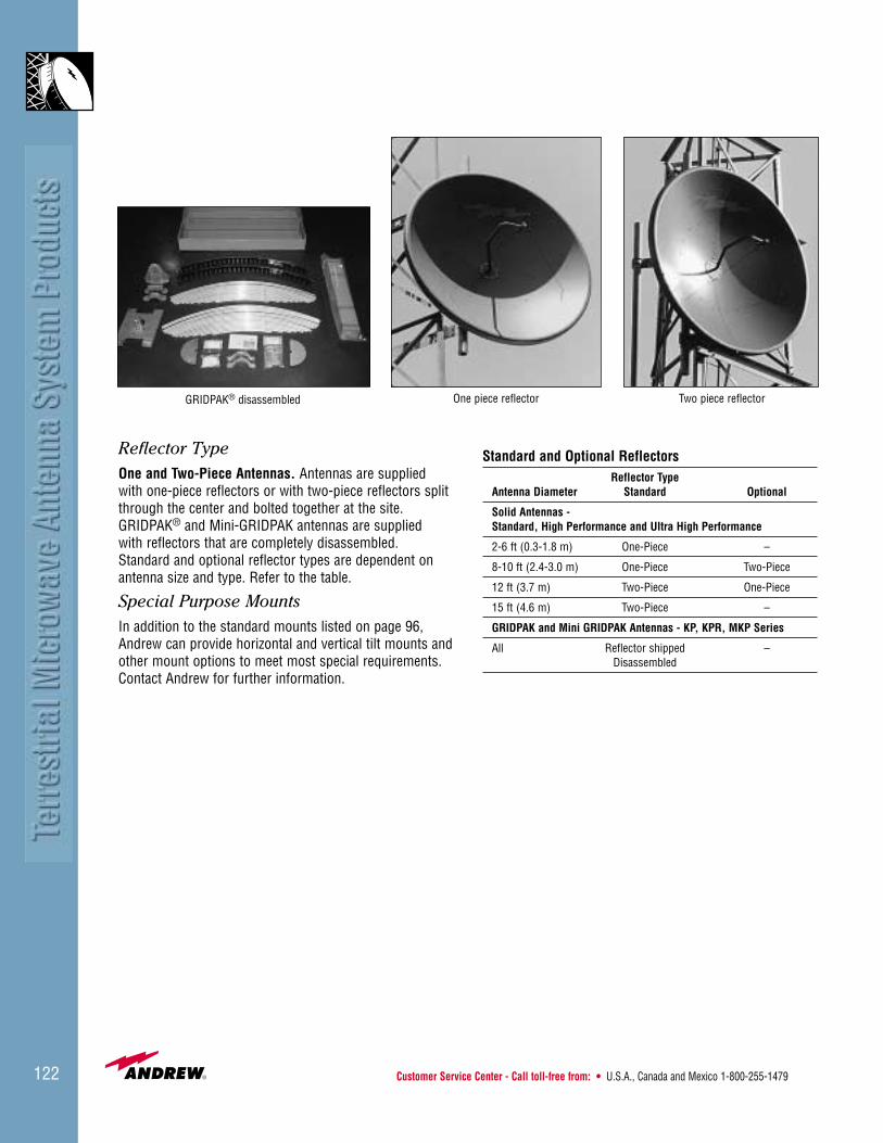
Customer Service Center - Call toll-free from: • U.S.A., Canada and Mexico 1-800-255-1479122
One piece reflectorGRIDPAK® disassembled Two piece reflector
Reflector TypeOne and Two-Piece Antennas. Antennas are suppliedwith one-piece reflectors or with two-piece reflectors splitthrough the center and bolted together at the site. GRIDPAK® and Mini-GRIDPAK antennas are supplied with reflectors that are completely disassembled.Standard and optional reflector types are dependent onantenna size and type. Refer to the table.
Special Purpose MountsIn addition to the standard mounts listed on page 96,Andrew can provide horizontal and vertical tilt mounts andother mount options to meet most special requirements.Contact Andrew for further information.
Standard and Optional ReflectorsReflector Type
Antenna Diameter Standard Optional
Solid Antennas - Standard, High Performance and Ultra High Performance
2-6 ft (0.3-1.8 m) One-Piece –
8-10 ft (2.4-3.0 m) One-Piece Two-Piece
12 ft (3.7 m) Two-Piece One-Piece
15 ft (4.6 m) Two-Piece –
GRIDPAK and Mini GRIDPAK Antennas - KP, KPR, MKP Series
All Reflector shipped –Disassembled
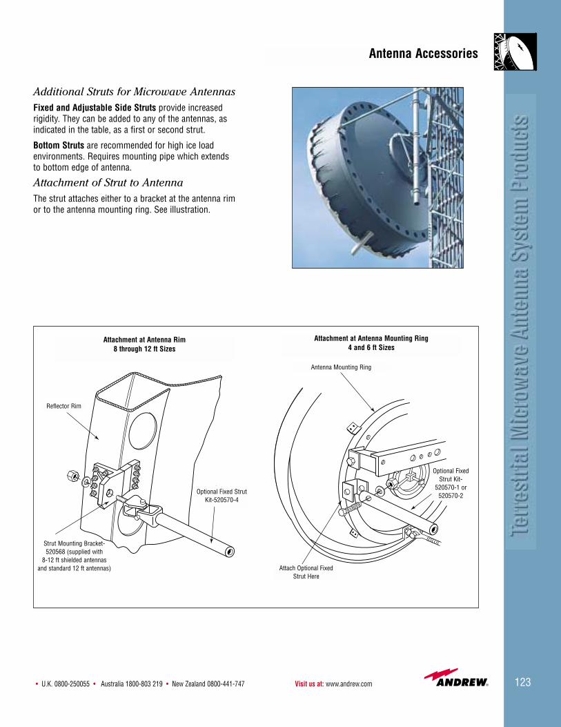
• U.K. 0800-250055 • Australia 1800-803 219 • New Zealand 0800-441-747 Visit us at: www.andrew.com 123
Additional Struts for Microwave AntennasFixed and Adjustable Side Struts provide increased rigidity. They can be added to any of the antennas, as indicated in the table, as a first or second strut.
Bottom Struts are recommended for high ice load environments. Requires mounting pipe which extends to bottom edge of antenna.
Attachment of Strut to AntennaThe strut attaches either to a bracket at the antenna rim or to the antenna mounting ring. See illustration.
Attachment at Antenna Rim8 through 12 ft Sizes
Attachment at Antenna Mounting Ring4 and 6 ft Sizes
Reflector Rim
Strut Mounting Bracket-520568 (supplied with
8-12 ft shielded antennasand standard 12 ft antennas)
Optional Fixed StrutKit-520570-4
Attach Optional FixedStrut Here
Antenna Mounting Ring
Optional FixedStrut Kit-
520570-1 or520570-2
Antenna Accessories
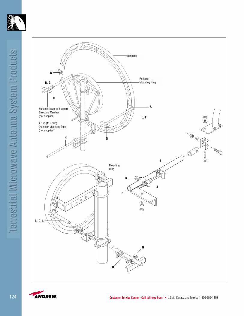
Customer Service Center - Call toll-free from: • U.S.A., Canada and Mexico 1-800-255-1479124
A
B, C
D
H G
E, F
ASuitable Tower or Support Structure Member (not supplied)
4.5 in (115 mm) Diameter Mounting Pipe (not supplied)
Reflector
ReflectorMounting Ring
J
I
K
MountingRing
B, C, L
D
G
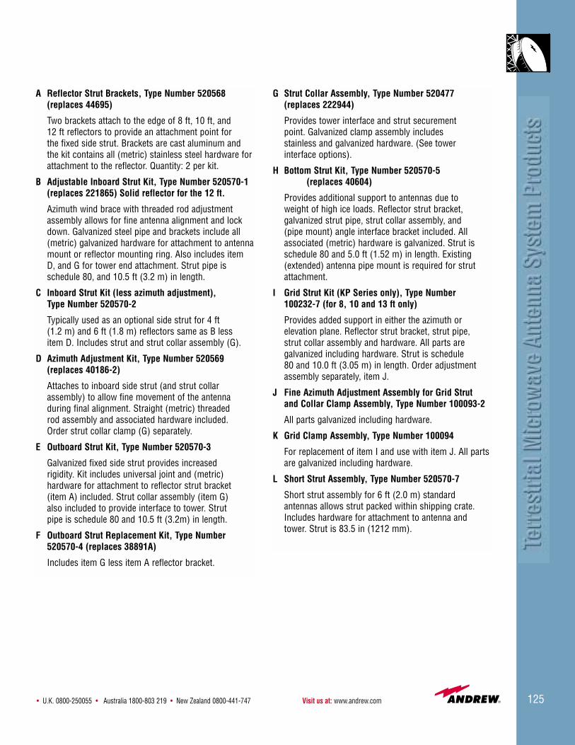
• U.K. 0800-250055 • Australia 1800-803 219 • New Zealand 0800-441-747 Visit us at: www.andrew.com 125
A Reflector Strut Brackets, Type Number 520568 (replaces 44695)
Two brackets attach to the edge of 8 ft, 10 ft, and 12 ft reflectors to provide an attachment point for the fixed side strut. Brackets are cast aluminum and the kit contains all (metric) stainless steel hardware forattachment to the reflector. Quantity: 2 per kit.
B Adjustable Inboard Strut Kit, Type Number 520570-1 (replaces 221865) Solid reflector for the 12 ft.
Azimuth wind brace with threaded rod adjustment assembly allows for fine antenna alignment and lock down. Galvanized steel pipe and brackets include all (metric) galvanized hardware for attachment to antennamount or reflector mounting ring. Also includes item D, and G for tower end attachment. Strut pipe is schedule 80, and 10.5 ft (3.2 m) in length.
C Inboard Strut Kit (less azimuth adjustment), Type Number 520570-2
Typically used as an optional side strut for 4 ft (1.2 m) and 6 ft (1.8 m) reflectors same as B less item D. Includes strut and strut collar assembly (G).
D Azimuth Adjustment Kit, Type Number 520569 (replaces 40186-2)
Attaches to inboard side strut (and strut collar assembly) to allow fine movement of the antenna during final alignment. Straight (metric) threaded rod assembly and associated hardware included. Order strut collar clamp (G) separately.
E Outboard Strut Kit, Type Number 520570-3
Galvanized fixed side strut provides increased rigidity. Kit includes universal joint and (metric) hardware for attachment to reflector strut bracket (item A) included. Strut collar assembly (item G) also included to provide interface to tower. Strut pipe is schedule 80 and 10.5 ft (3.2m) in length.
F Outboard Strut Replacement Kit, Type Number 520570-4 (replaces 38891A)
Includes item G less item A reflector bracket.
G Strut Collar Assembly, Type Number 520477 (replaces 222944)
Provides tower interface and strut securement point. Galvanized clamp assembly includes stainless and galvanized hardware. (See tower interface options).
H Bottom Strut Kit, Type Number 520570-5 (replaces 40604)
Provides additional support to antennas due to weight of high ice loads. Reflector strut bracket, galvanized strut pipe, strut collar assembly, and (pipe mount) angle interface bracket included. All associated (metric) hardware is galvanized. Strut is schedule 80 and 5.0 ft (1.52 m) in length. Existing (extended) antenna pipe mount is required for strut attachment.
I Grid Strut Kit (KP Series only), Type Number 100232-7 (for 8, 10 and 13 ft only)
Provides added support in either the azimuth or elevation plane. Reflector strut bracket, strut pipe, strut collar assembly and hardware. All parts are galvanized including hardware. Strut is schedule 80 and 10.0 ft (3.05 m) in length. Order adjustment assembly separately, item J.
J Fine Azimuth Adjustment Assembly for Grid Strut and Collar Clamp Assembly, Type Number 100093-2
All parts galvanized including hardware.
K Grid Clamp Assembly, Type Number 100094
For replacement of item I and use with item J. All partsare galvanized including hardware.
L Short Strut Assembly, Type Number 520570-7
Short strut assembly for 6 ft (2.0 m) standard antennas allows strut packed within shipping crate. Includes hardware for attachment to antenna and tower. Strut is 83.5 in (1212 mm).
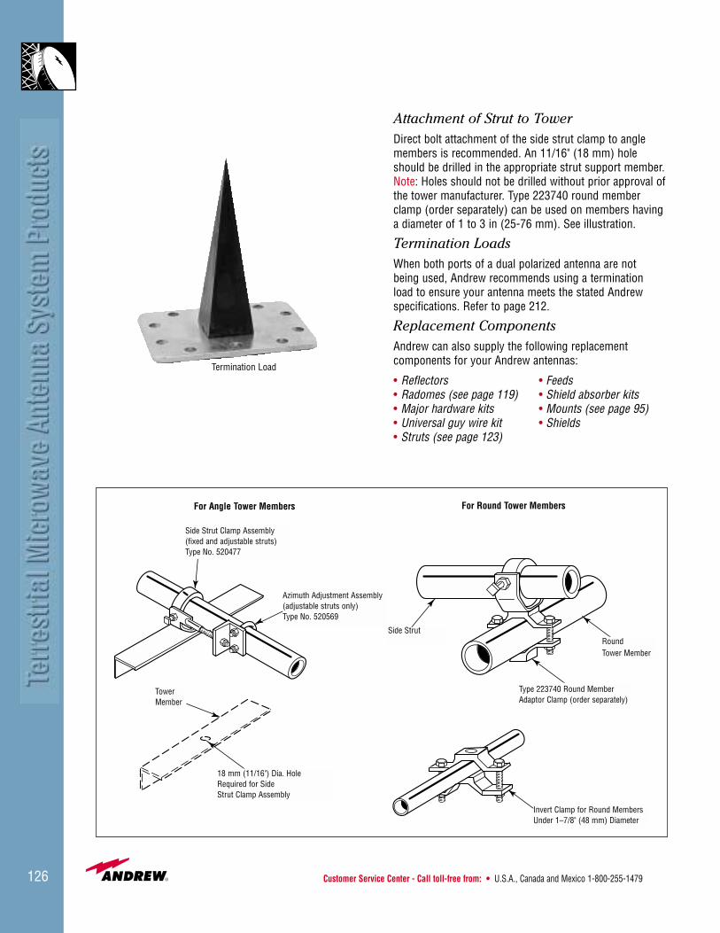
Customer Service Center - Call toll-free from: • U.S.A., Canada and Mexico 1-800-255-1479126
Attachment of Strut to TowerDirect bolt attachment of the side strut clamp to anglemembers is recommended. An 11/16" (18 mm) holeshould be drilled in the appropriate strut support member.Note: Holes should not be drilled without prior approval ofthe tower manufacturer. Type 223740 round memberclamp (order separately) can be used on members havinga diameter of 1 to 3 in (25-76 mm). See illustration.
Termination LoadsWhen both ports of a dual polarized antenna are not being used, Andrew recommends using a termination load to ensure your antenna meets the stated Andrew specifications. Refer to page 212.
Replacement ComponentsAndrew can also supply the following replacement components for your Andrew antennas:
• Reflectors • Feeds• Radomes (see page 119) • Shield absorber kits• Major hardware kits • Mounts (see page 95)• Universal guy wire kit • Shields• Struts (see page 123)
For Round Tower Members
Type 223740 Round MemberAdaptor Clamp (order separately)
Invert Clamp for Round MembersUnder 1–7/8" (48 mm) Diameter
RoundTower Member
Side Strut
18 mm (11/16") Dia. HoleRequired for SideStrut Clamp Assembly
TowerMember
Azimuth Adjustment Assembly(adjustable struts only)Type No. 520569
Side Strut Clamp Assembly(fixed and adjustable struts)Type No. 520477
For Angle Tower Members
Termination Load
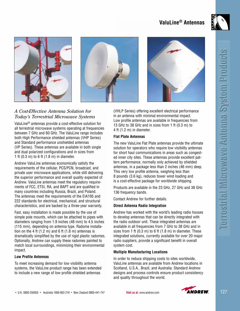
• U.K. 0800-250055 • Australia 1800-803 219 • New Zealand 0800-441-747 Visit us at: www.andrew.com 127
ValuLine® Antennas
A Cost-Effective Antenna Solution forToday’s Terrestrial Microwave SystemsValuLine® antennas provide a cost-effective solution forall terrestrial microwave systems operating at frequenciesbetween 7 GHz and 60 GHz. The ValuLine range includesboth High Performance shielded antennas (VHP Series)and Standard performance unshielded antennas (VP Series). These antennas are available in both singleand dual polarized configurations and in sizes from 1 ft (0.3 m) to 6 ft (1.8 m) in diameter.
Andrew ValuLine antennas economically satisfy therequirements of the cellular, PCS/PCN, broadcast, and private user microwave applications, while still deliveringthe superior performance and overall quality expected ofAndrew. ValuLine antennas meet the regulatory require-ments of FCC, ETSI, RA, and BAPT and are qualified inmany countries including Russia, Brazil, and Poland.The antennas meet the requirements of the EIA195 and222 standards for electrical, mechanical, and structural characteristics, and are backed by a three-year warranty.
Fast, easy installation is made possible by the use of simple pole mounts, which can be attached to pipes withdiameters ranging from 1.9 inches (48 mm) to 4.5 inches(115 mm), depending on antenna type. Radome installa-tion on the 4 ft (1.2 m) and 6 ft (1.8 m) antennas is dramatically simplified by the use of rigid plastic radomes.Optionally, Andrew can supply these radomes painted tomatch local surroundings, minimizing their environmentalimpact.
Low Profile Antennas
To meet increasing demand for low visibility antenna systems, the ValuLine product range has been extended to include a new range of low profile shielded antennas
(VHLP Series) offering excellent electrical performance in an antenna with minimal environmental impact. Low profile antennas are available in frequencies from 13 GHz to 38 GHz and in sizes from 1 ft (0.3 m) to 4 ft (1.2 m) in diameter.
Flat Plate Antennas
The new ValuLine Flat Plate antennas provide the ultimatesolution for operators who require low visibility antennasfor short haul communications in areas such as congest-ed inner city sites. These antennas provide excellent pat-tern performance, normally only achieved by shieldedantennas, in a package less than 2 inches (46 mm) deep.This very low profile antenna, weighing less than 8 pounds (3.6 kg), reduces tower wind loading and is a cost-effective package for worldwide shipping.
Products are available in the 23 GHz, 27 GHz and 38 GHz 136 frequency bands.
Contact Andrew for further details.
Direct Antenna Radio Integration
Andrew has worked with the world’s leading radio housesto develop antennas that can be directly integrated withthe radio outdoor unit. These integrated antennas areavailable in all frequencies from 7 GHz to 38 GHz and insizes from 1 ft (0.3 m) to 6 ft (1.8 m) in diameter. Theseintegrated solutions, currently available for over 20 majorradio suppliers, provide a significant benefit in overall system cost.
Multiple Manufacturing Locations
In order to reduce shipping costs to sites worldwide,ValuLine antennas are available from Andrew locations inScotland, U.S.A., Brazil, and Australia. Standard Andrewdesigns and process controls ensure product consistencyand quality throughout the world.
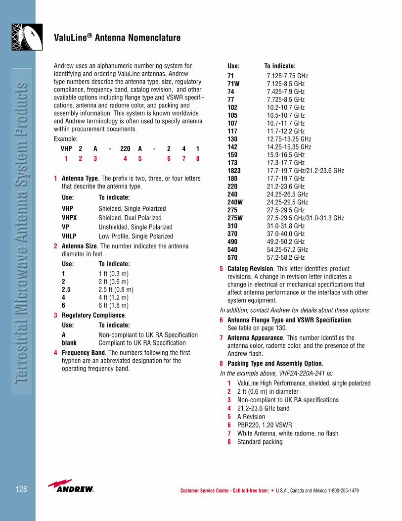
Customer Service Center - Call toll-free from: • U.S.A., Canada and Mexico 1-800-255-1479128
ValuLine® Antenna Nomenclature
Andrew uses an alphanumeric numbering system foridentifying and ordering ValuLine antennas. Andrew type numbers describe the antenna type, size, regulatorycompliance, frequency band, catalog revision, and otheravailable options including flange type and VSWR specifi-cations, antenna and radome color, and packing andassembly information. This system is known worldwideand Andrew terminology is often used to specify antennawithin procurement documents.Example:
VHP 2 A - 220 A - 2 4 11 2 3 4 5 6 7 8
1 Antenna Type. The prefix is two, three, or four letters that describe the antenna type.
Use: To indicate:
VHP Shielded, Single PolarizedVHPX Shielded, Dual PolarizedVP Unshielded, Single PolarizedVHLP Low Profile, Single Polarized
2 Antenna Size. The number indicates the antenna diameter in feet.Use: To indicate:1 1 ft (0.3 m)2 2 ft (0.6 m)2.5 2.5 ft (0.8 m)4 4 ft (1.2 m)6 6 ft (1.8 m)
3 Regulatory Compliance.Use: To indicate:A Non-compliant to UK RA Specificationblank Compliant to UK RA Specification
4 Frequency Band. The numbers following the first hyphen are an abbreviated designation for the operating frequency band.
Use: To indicate:71 7.125-7.75 GHz71W 7.125-8.5 GHz74 7.425-7.9 GHz77 7.725-8.5 GHz102 10.2-10.7 GHz105 10.5-10.7 GHz107 10.7-11.7 GHz117 11.7-12.2 GHz130 12.75-13.25 GHz142 14.25-15.35 GHz159 15.9-16.5 GHz173 17.3-17.7 GHz1823 17.7-19.7 GHz/21.2-23.6 GHz180 17.7-19.7 GHz220 21.2-23.6 GHz240 24.25-26.5 GHz240W 24.25-29.5 GHz275 27.5-29.5 GHz275W 27.5-29.5 GHz/31.0-31.3 GHz310 31.0-31.8 GHz370 37.0-40.0 GHz490 49.2-50.2 GHz540 54.25-57.2 GHz570 57.2-58.2 GHz
5 Catalog Revision. This letter identifies product revisions. A change in revision letter indicates a change in electrical or mechanical specifications that affect antenna performance or the interface with other system equipment.
In addition, contact Andrew for details about these options:6 Antenna Flange Type and VSWR Specification.
See table on page 130.7 Antenna Appearance. This number identifies the
antenna color, radome color, and the presence of the Andrew flash.
8 Packing Type and Assembly Option. In the example above, VHP2A-220A-241 is:
1 ValuLine High Performance, shielded, single polarized2 2 ft (0.6 m) in diameter3 Non-compliant to UK RA specifications4 21.2-23.6 GHz band5 A Revision6 PBR220, 1.20 VSWR7 White Antenna, white radome, no flash8 Standard packing

• U.K. 0800-250055 • Australia 1800-803 219 • New Zealand 0800-441-747 Visit us at: www.andrew.com 129
E-Series ValuLine® Antennasfor Use in Extreme Environments
ValuLine® antennas are now available in upgraded versions that allow them to be used in locations subjected to high wind load or corrosive environments.
These antennas, available in diameters of 1 ft (0.3 m), 2 ft (0.6 m), 2.5 (0.8 m), 4 ft (1.2 m), and 6 ft (1.8 m),are mechanically upgraded to withstand 155 mph (250 km/h) through the use of additional struts andstrengthened reflectors.
The antennas also include additional treatments that willprovide long-term protection in marine, urban, and mostindustrial environments:
• Factory applied epoxy painting
• Hot-dip galvanizing
• Stainless steel hardware
• Corrosion inhibiting compounds
Contact Andrew for more information.
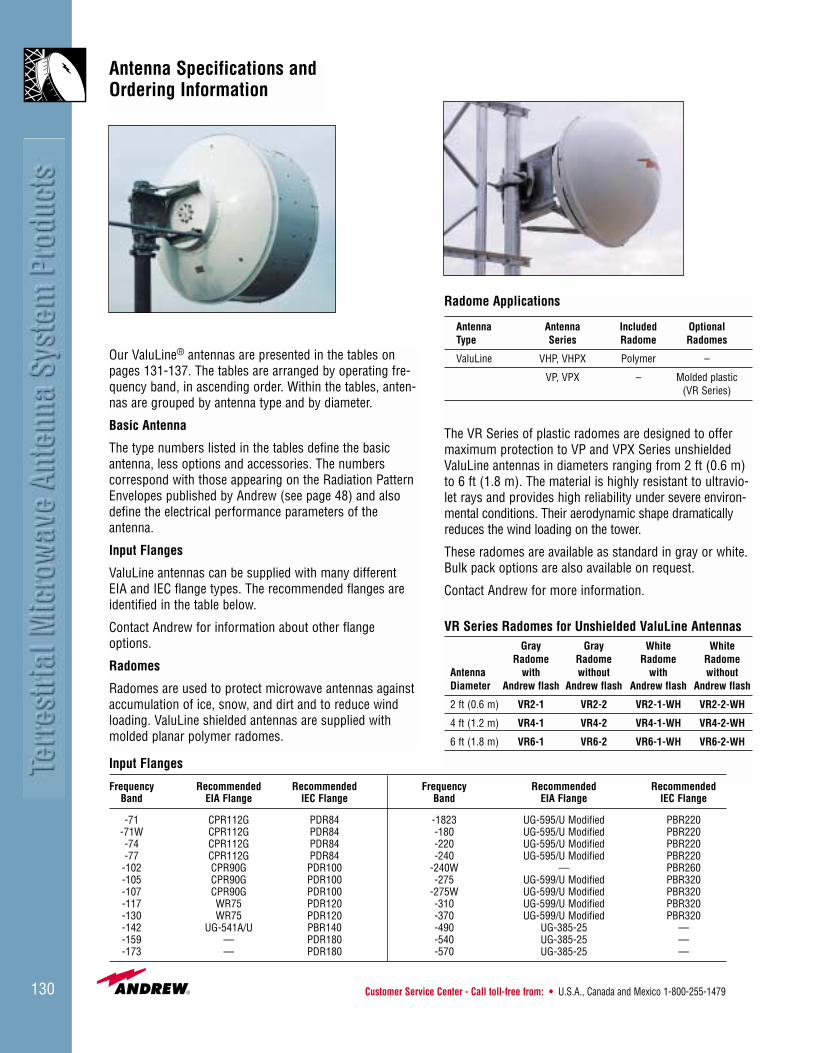
Customer Service Center - Call toll-free from: • U.S.A., Canada and Mexico 1-800-255-1479130
Antenna Specifications andOrdering Information
Our ValuLine® antennas are presented in the tables onpages 131-137. The tables are arranged by operating fre-quency band, in ascending order. Within the tables, anten-nas are grouped by antenna type and by diameter.
Basic Antenna
The type numbers listed in the tables define the basicantenna, less options and accessories. The numbers correspond with those appearing on the Radiation PatternEnvelopes published by Andrew (see page 48) and alsodefine the electrical performance parameters of the antenna.
Input Flanges
ValuLine antennas can be supplied with many differentEIA and IEC flange types. The recommended flanges areidentified in the table below.
Contact Andrew for information about other flangeoptions.
Radomes
Radomes are used to protect microwave antennas againstaccumulation of ice, snow, and dirt and to reduce windloading. ValuLine shielded antennas are supplied withmolded planar polymer radomes.
Radome Applications
Antenna Antenna Included OptionalType Series Radome Radomes
ValuLine VHP, VHPX Polymer –
VP, VPX – Molded plastic (VR Series)
The VR Series of plastic radomes are designed to offermaximum protection to VP and VPX Series unshieldedValuLine antennas in diameters ranging from 2 ft (0.6 m)to 6 ft (1.8 m). The material is highly resistant to ultravio-let rays and provides high reliability under severe environ-mental conditions. Their aerodynamic shape dramaticallyreduces the wind loading on the tower.
These radomes are available as standard in gray or white.Bulk pack options are also available on request.
Contact Andrew for more information.
VR Series Radomes for Unshielded ValuLine AntennasGray Gray White White
Radome Radome Radome RadomeAntenna with without with withoutDiameter Andrew flash Andrew flash Andrew flash Andrew flash
2 ft (0.6 m) VR2-1 VR2-2 VR2-1-WH VR2-2-WH
4 ft (1.2 m) VR4-1 VR4-2 VR4-1-WH VR4-2-WH
6 ft (1.8 m) VR6-1 VR6-2 VR6-1-WH VR6-2-WH
Input Flanges
Frequency Recommended Recommended Frequency Recommended RecommendedBand EIA Flange IEC Flange Band EIA Flange IEC Flange
-71 CPR112G PDR84 -1823 UG-595/U Modified PBR220-71W CPR112G PDR84 -180 UG-595/U Modified PBR220-74 CPR112G PDR84 -220 UG-595/U Modified PBR220-77 CPR112G PDR84 -240 UG-595/U Modified PBR220-102 CPR90G PDR100 -240W — PBR260-105 CPR90G PDR100 -275 UG-599/U Modified PBR320-107 CPR90G PDR100 -275W UG-599/U Modified PBR320-117 WR75 PDR120 -310 UG-599/U Modified PBR320-130 WR75 PDR120 -370 UG-599/U Modified PBR320-142 UG-541A/U PBR140 -490 UG-385-25 —-159 — PDR180 -540 UG-385-25 —-173 — PDR180 -570 UG-385-25 —
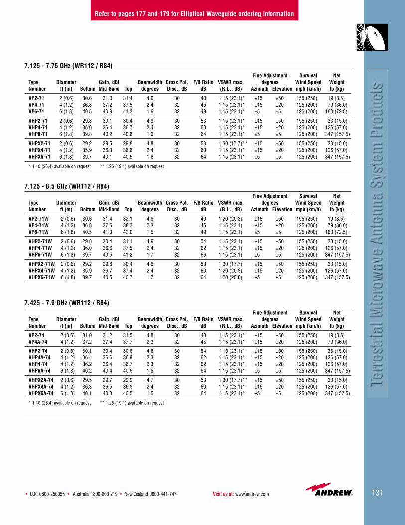
• U.K. 0800-250055 • Australia 1800-803 219 • New Zealand 0800-441-747 Visit us at: www.andrew.com 131
7.125 - 7.75 GHz (WR112 / R84)Fine Adjustment Survival Net
Type Diameter Gain, dBi Beamwidth Cross Pol. F/B Ratio VSWR max. degrees Wind Speed WeightNumber ft (m) Bottom Mid-Band Top degrees Disc., dB dB (R.L., dB) Azimuth Elevation mph (km/h) lb (kg)
VP2-71 2 (0.6) 30.6 31.0 31.4 4.9 30 40 1.15 (23.1)* ±15 ±50 155 (250) 19 (8.5)VP4-71 4 (1.2) 36.8 37.2 37.5 2.4 32 45 1.15 (23.1)* ±15 ±20 125 (200) 79 (36.0)VP6-71 6 (1.8) 40.5 40.9 41.3 1.6 32 49 1.15 (23.1)* ±5 ±5 125 (200) 160 (72.5)
VHP2-71 2 (0.6) 29.8 30.1 30.4 4.9 30 53 1.15 (23.1)* ±15 ±50 155 (250) 33 (15.0)VHP4-71 4 (1.2) 36.0 36.4 36.7 2.4 32 60 1.15 (23.1)* ±15 ±20 125 (200) 126 (57.0)VHP6-71 6 (1.8) 39.8 40.2 40.6 1.6 32 64 1.15 (23.1)* ±5 ±5 125 (200) 347 (157.5)
VHPX2-71 2 (0.6) 29.2 29.5 29.8 4.8 30 53 1.30 (17.7)** ±15 ±50 155 (250) 33 (15.0)VHPX4-71 4 (1.2) 35.9 36.3 36.6 2.4 32 60 1.15 (23.1)* ±15 ±20 125 (200) 126 (57.0)VHPX6-71 6 (1.8) 39.7 40.1 40.5 1.6 32 64 1.15 (23.1)* ±5 ±5 125 (200) 347 (157.5)
* 1.10 (26.4) available on request ** 1.25 (19.1) available on request
7.125 - 8.5 GHz (WR112 / R84)Fine Adjustment Survival Net
Type Diameter Gain, dBi Beamwidth Cross Pol. F/B Ratio VSWR max. degrees Wind Speed WeightNumber ft (m) Bottom Mid-Band Top degrees Disc., dB dB (R.L., dB) Azimuth Elevation mph (km/h) lb (kg)
VP2-71W 2 (0.6) 30.6 31.4 32.1 4.8 30 40 1.20 (20.8) ±15 ±50 155 (250) 19 (8.5)VP4-71W 4 (1.2) 36.8 37.5 38.3 2.3 32 45 1.15 (23.1) ±15 ±20 125 (200) 79 (36.0)VP6-71W 6 (1.8) 40.5 41.3 42.0 1.5 32 49 1.15 (23.1) ±5 ±5 125 (200) 160 (72.5)
VHP2-71W 2 (0.6) 29.8 30.4 31.1 4.9 30 54 1.15 (23.1) ±15 ±50 155 (250) 33 (15.0)VHP4-71W 4 (1.2) 36.0 36.6 37.5 2.4 32 62 1.15 (23.1) ±15 ±20 125 (200) 126 (57.0)VHP6-71W 6 (1.8) 39.7 40.5 41.2 1.7 32 66 1.15 (23.1) ±5 ±5 125 (200) 347 (157.5)
VHPX2-71W 2 (0.6) 29.2 29.8 30.4 4.8 30 53 1.30 (17.7) ±15 ±50 155 (250) 33 (15.0)VHPX4-71W 4 (1.2) 35.9 36.7 37.4 2.4 32 60 1.20 (20.8) ±15 ±20 125 (200) 126 (57.0)VHPX6-71W 6 (1.8) 39.7 40.5 40.7 1.7 32 64 1.20 (20.8) ±5 ±5 125 (200) 347 (157.5)
7.425 - 7.9 GHz (WR112 / R84)Fine Adjustment Survival Net
Type Diameter Gain, dBi Beamwidth Cross Pol. F/B Ratio VSWR max. degrees Wind Speed WeightNumber ft (m) Bottom Mid-Band Top degrees Disc., dB dB (R.L., dB) Azimuth Elevation mph (km/h) lb (kg)
VP2-74 2 (0.6) 31.0 31.2 31.5 4.8 30 40 1.15 (23.1)* ±15 ±50 155 (250) 19 (8.5)VP4A-74 4 (1.2) 37.2 37.4 37.7 2.3 32 45 1.15 (23.1)* ±15 ±20 125 (200) 79 (36.0)
VHP2-74 2 (0.6) 30.1 30.4 30.6 4.8 30 54 1.15 (23.1)* ±15 ±50 155 (250) 33 (15.0)VHP4A-74 4 (1.2) 36.4 36.6 36.9 2.3 32 62 1.15 (23.1)* ±15 ±20 125 (200) 126 (57.0)VHP4-74 4 (1.2) 36.2 36.4 36.7 2.3 32 62 1.15 (23.1)* ±15 ±20 125 (200) 126 (57.0)VHP6A-74 6 (1.8) 40.2 40.4 40.6 1.5 32 64 1.15 (23.1)* ±5 ±5 125 (200) 347 (157.5)
VHPX2A-74 2 (0.6) 29.5 29.7 29.9 4.7 30 53 1.30 (17.7)** ±15 ±50 155 (250) 33 (15.0)VHPX4A-74 4 (1.2) 36.3 36.5 36.8 2.4 32 60 1.15 (23.1)* ±15 ±20 125 (200) 126 (57.0)VHPX6A-74 6 (1.8) 40.1 40.3 40.5 1.5 32 64 1.15 (23.1)* ±5 ±5 125 (200) 347 (157.5)
* 1.10 (26.4) available on request ** 1.25 (19.1) available on request
Refer to pages 177 and 179 for Elliptical Waveguide ordering information
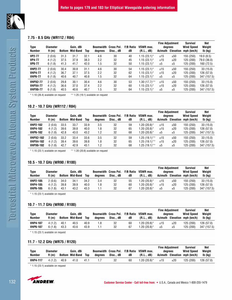
Customer Service Center - Call toll-free from: • U.S.A., Canada and Mexico 1-800-255-1479132
7.75 - 8.5 GHz (WR112 / R84)Fine Adjustment Survival Net
Type Diameter Gain, dBi Beamwidth Cross Pol. F/B Ratio VSWR max. degrees Wind Speed WeightNumber ft (m) Bottom Mid-Band Top degrees Disc., dB dB (R.L., dB) Azimuth Elevation mph (km/h) lb (kg)
VP2-77 2 (0.6) 31.3 31.7 32.1 4.6 30 40 1.15 (23.1)* ±15 ±50 155 (250) 19.0 (8.5)VP4-77 4 (1.2) 37.5 37.9 38.3 2.2 32 45 1.15 (23.1)* ±15 ±20 125 (200) 79.0 (36.0)VP6-77 6 (1.8) 41.3 41.7 42.0 1.5 32 50 1.15 (23.1)* ±5 ±5 125 (200) 160 (72.5)
VHP2-77 2 (0.6) 30.4 30.8 31.1 4.6 30 54 1.15 (23.1)* ±15 ±50 155 (250) 33 (15.0)VHP4-77 4 (1.2) 36.7 37.1 37.5 2.2 32 62 1.15 (23.1)* ±15 ±20 125 (200) 126 (57.0)VHP6-77 6 (1.8) 40.6 40.7 40.8 1.5 32 64 1.15 (23.1)* ±5 ±5 125 (200) 347 (157.5)
VHPX2-77 2 (0.6) 29.8 30.1 30.4 4.6 30 53 1.30 (17.7)** ±15 ±50 155 (250) 33 (15.0)VHPX4-77 4 (1.2) 36.6 37.0 37.4 2.2 32 60 1.15 (23.1)* ±15 ±20 125 (200) 126 (57.0)VHPX6-77 6 (1.8) 40.5 40.6 40.7 1.5 32 64 1.15 (23.1)* ±5 ±5 125 (200) 347 (157.5)
* 1.10 (26.4) available on request ** 1.25 (19.1) available on request
10.2 - 10.7 GHz (WR112 / R84)Fine Adjustment Survival Net
Type Diameter Gain, dBi Beamwidth Cross Pol. F/B Ratio VSWR max. degrees Wind Speed WeightNumber ft (m) Bottom Mid-Band Top degrees Disc., dB dB (R.L., dB) Azimuth Elevation mph (km/h) lb (kg)
VHP2-102 2 (0.6) 33.5 33.7 33.9 3.5 32 59 1.20 (20.8)* ±15 ±50 155 (250) 33 (15.0)VHP4-102 4 (1.2) 39.6 39.8 40.0 1.8 32 65 1.20 (20.8)* ±15 ±20 125 (200) 126 (57.0)VHP6-102 6 (1.8) 42.8 43.0 43.2 1.2 32 68 1.20 (20.8)* ±5 ±5 125 (200) 347 (157.5)
VHPX2-102 2 (0.6) 33.2 33.4 33.6 3.5 32 59 1.25 (19.1)** ±15 ±50 155 (250) 33 (15.0)VHPX4-102 4 (1.2) 39.4 39.6 39.8 1.8 32 65 1.25 (19.1)** ±15 ±20 125 (200) 126 (57.0)VHPX6-102 6 (1.8) 42.7 42.9 43.1 1.2 32 68 1.25 (19.1)** ±5 ±5 125 (200) 347 (157.5)
* 1.15 (23.1) available on request ** 1.20 (20.8) available on request
10.5 - 10.7 GHz (WR90 / R100)Fine Adjustment Survival Net
Type Diameter Gain, dBi Beamwidth Cross Pol. F/B Ratio VSWR max. degrees Wind Speed WeightNumber ft (m) Bottom Mid-Band Top degrees Disc., dB dB (R.L., dB) Azimuth Elevation mph (km/h) lb (kg)
VHP2-105 2 (0.6) 34.0 34.1 34.2 3.4 32 55 1.20 (20.8)* ±15 ±50 155 (250) 33 (15.0)VHP4-105 4 (1.2) 39.8 39.9 40.0 1.8 32 60 1.20 (20.8)* ±15 ±20 125 (200) 126 (57.0)VHP6-105 6 (1.8) 43.1 43.2 43.3 1.1 32 67 1.20 (20.8)* ±5 ±5 125 (200) 347 (157.5)
* 1.15 (23.1) available on request
10.7 - 11.7 GHz (WR90 / R100)Fine Adjustment Survival Net
Type Diameter Gain, dBi Beamwidth Cross Pol. F/B Ratio VSWR max. degrees Wind Speed WeightNumber ft (m) Bottom Mid-Band Top degrees Disc., dB dB (R.L., dB) Azimuth Elevation mph (km/h) lb (kg)
VHP4-107 4 (1.2) 40.1 40.5 40.9 1.8 32 60 1.20 (20.8)* ±15 ±20 125 (200) 126 (57.0)VHP6-107 6 (1.8) 43.3 43.6 43.9 1.1 32 67 1.20 (20.8)* ±5 ±5 125 (200) 347 (157.5)
* 1.15 (23.1) available on request
11.7 - 12.2 GHz (WR75 / R120)Fine Adjustment Survival Net
Type Diameter Gain, dBi Beamwidth Cross Pol. F/B Ratio VSWR max. degrees Wind Speed WeightNumber ft (m) Bottom Mid-Band Top degrees Disc., dB dB (R.L., dB) Azimuth Elevation mph (km/h) lb (kg)
VHP4-117 4 (1.2) 40.9 41.0 41.1 1.7 32 60 1.20 (20.8)* ±15 ±20 125 (200) 126 (57.0)
* 1.15 (23.1) available on request
Refer to pages 179 and 183 for Elliptical Waveguide ordering information
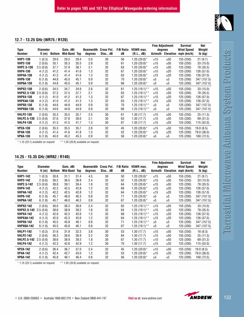
• U.K. 0800-250055 • Australia 1800-803 219 • New Zealand 0800-441-747 Visit us at: www.andrew.com 133
12.7 - 13.25 GHz (WR75 / R120)Fine Adjustment Survival Net
Type Diameter Gain, dBi Beamwidth Cross Pol. F/B Ratio VSWR max. degrees Wind Speed WeightNumber ft (m) Bottom Mid-Band Top degrees Disc., dB dB (R.L., dB) Azimuth Elevation mph (km/h) lb (kg)
VHP1-130 1 (0.3) 29.0 29.2 29.4 5.0 30 56 1.20 (20.8)* ±15 ±50 155 (250) 21 (9.7)VHP2-130 2 (0.6) 35.1 35.3 35.5 2.8 32 61 1.20 (20.8)* ±15 ±50 155 (250) 33 (15.0)VHP2.5-130 2.5 (0.8) 37.7 37.9 38.1 2.1 32 63 1.20 (20.8)* ±15 ±50 125 (200) 78 (35.5)VHP4-130 4 (1.2) 41.2 41.4 41.6 1.3 32 67 1.20 (20.8)* ±15 ±20 125 (200) 126 (57.0)VHP4A-130 4 (1.2) 41.2 41.4 41.6 1.3 32 63 1.20 (20.8)* ±15 ±20 125 (200) 126 (57.0)VHP6-130 6 (1.8) 44.8 45.0 45.1 0.9 32 70 1.20 (20.8)* ±5 ±5 125 (200) 347 (157.5)VHP6A-130 6 (1.8) 44.8 45.0 45.1 0.9 32 66 1.20 (20.8)* ±5 ±5 125 (200) 347 (157.5)
VHPX2-130 2 (0.6) 34.5 34.7 34.9 2.8 32 61 1.25 (19.1)** ±15 ±50 155 (250) 33 (15.0)VHPX2.5-130 2.5 (0.8) 37.2 37.5 37.7 2.1 32 63 1.25 (19.1)** ±15 ±50 125 (200) 78 (35.5)VHPX4-130 4 (1.2) 41.0 41.2 41.3 1.3 32 67 1.25 (19.1)** ±15 ±20 125 (200) 126 (57.0)VHPX4A-130 4 (1.2) 41.0 41.2 41.3 1.3 32 63 1.25 (19.1)** ±15 ±20 125 (200) 126 (57.0)VHPX6-130 6 (1.8) 44.6 44.8 44.9 0.9 32 70 1.25 (19.1)** ±5 ±5 125 (200) 347 (157.5)VHPX6A-130 6 (1.8) 44.6 44.8 44.9 0.9 32 66 1.25 (19.1)** ±5 ±5 125 (200) 347 (157.5)
VHLP2-130 2 (0.6) 35.3 35.5 35.7 2.5 30 61 1.30 (17.7) ±15 ±50 155 (250) 25 (11.3)VHLP2.5-130 2.5 (0.8) 37.6 37.8 38.0 2.1 30 63 1.30 (17.7) ±15 ±50 125 (200) 69 (31.2)VHLP4-130 4 (1.2) 41.3 41.5 41.7 1.3 30 67 1.30 (17.7) ±15 ±20 125 (200) 115 (52.0)
VP2A-130 2 (0.6) 35.3 35.5 35.7 2.8 32 45 1.20 (20.8)* ±15 ±50 155 (250) 19.0 (8.5)VP4A-130 4 (1.2) 41.4 41.6 41.8 1.3 32 52 1.20 (20.8)* ±15 ±20 125 (200) 79.0 (36.0)VP6A-130 6 (1.8) 45.0 45.2 45.3 0.9 32 58 1.20 (20.8)* ±5 ±5 125 (200) 160 (72.5)
* 1.15 (23.1) available on request ** 1.20 (20.8) available on request
14.25 - 15.35 GHz (WR62 / R140)Fine Adjustment Survival Net
Type Diameter Gain, dBi Beamwidth Cross Pol. F/B Ratio VSWR max. degrees Wind Speed WeightNumber ft (m) Bottom Mid-Band Top degrees Disc., dB dB (R.L., dB) Azimuth Elevation mph (km/h) lb (kg)
VHP1-142 1 (0.3) 30.8 31.1 31.4 4.5 30 50 1.20 (20.8)* ±15 ±50 155 (250) 21 (9.7)VHP2-142 2 (0.6) 36.2 36.5 36.8 2.4 32 62 1.20 (20.8)* ±15 ±50 155 (250) 33 (15.0)VHP2.5-142 2.5 (0.8) 38.8 39.1 39.4 1.8 32 64 1.20 (20.8)* ±15 ±50 125 (200) 78 (35.5)VHP4-142 4 (1.2) 42.2 42.5 42.8 1.2 32 68 1.20 (20.8)* ±15 ±20 125 (200) 126 (57.0)VHP4A-142 4 (1.2) 42.2 42.5 42.8 1.2 32 64 1.20 (20.8)* ±15 ±20 125 (200) 126 (57.0)VHP6-142 6 (1.8) 45.7 46.0 46.3 0.8 32 71 1.20 (20.8)* ±5 ±5 125 (200) 347 (157.5)VHP6A-142 6 (1.8) 45.7 46.0 46.3 0.8 32 67 1.20 (20.8)* ±5 ±5 125 (200) 347 (157.5)
VHPX2-142 2 (0.6) 36.0 36.3 36.6 2.4 32 62 1.25 (19.1)** ±15 ±50 155 (250) 33 (15.0)VHPX2.5-142 2.5 (0.8) 38.6 38.9 39.2 1.8 32 64 1.25 (19.1)** ±15 ±50 125 (200) 78 (35.5)VHPX4-142 4 (1.2) 42.0 42.3 42.6 1.2 32 68 1.25 (19.1)** ±15 ±20 125 (200) 126 (57.0)VHPX4A-142 4 (1.2) 42.0 42.3 42.6 1.2 32 64 1.25 (19.1)** ±15 ±20 125 (200) 126 (57.0)VHPX6-142 6 (1.8) 45.5 45.8 46.1 0.8 32 71 1.25 (19.1)** ±5 ±5 125 (200) 347 (157.5)VHPX6A-142 6 (1.8) 45.5 45.8 46.1 0.8 32 67 1.25 (19.1)** ±5 ±5 125 (200) 347 (157.5)
VHLP1-142 1 (0.3) 31.6 31.9 32.3 3.8 30 53 1.30 (17.7) ±15 ±50 155 (250) 18 (8.3)VHLP2-142 2 (0.6) 36.3 36.6 36.9 2.2 30 64 1.30 (17.7) ±15 ±50 155 (250) 25 (11.3)VHLP2.5-142 2.5 (0.8) 38.6 38.9 39.3 1.8 30 67 1.30 (17.7) ±15 ±50 125 (200) 69 (31.2)VHLP4-142 4 (1.2) 42.3 42.6 42.9 1.2 30 70 1.30 (17.7) ±15 ±20 125 (200) 115 (52.0)
VP2A-142 2 (0.6) 36.4 36.7 37.0 2.4 32 45 1.20 (20.8)* ±15 ±50 155 (250) 19.0 (8.5)VP4A-142 4 (1.2) 42.4 42.7 43.0 1.2 32 53 1.20 (20.8)* ±15 ±20 125 (200) 79.0 (36.0)VP6A-142 6 (1.8) 45.8 46.1 46.4 0.8 32 56 1.20 (20.8)* ±5 ±5 125 (200) 160 (72.5)
* 1.15 (23.1) available on request ** 1.20 (20.8) available on request
Refer to pages 185 and 187 for Elliptical Waveguide ordering information
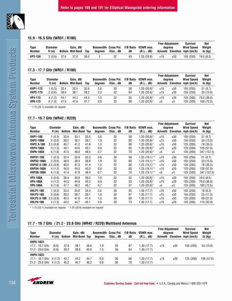
Customer Service Center - Call toll-free from: • U.S.A., Canada and Mexico 1-800-255-1479134
15.9 - 16.5 GHz (WR51 / R180)Fine Adjustment Survival Net
Type Diameter Gain, dBi Beamwidth Cross Pol. F/B Ratio VSWR max. degrees Wind Speed WeightNumber ft (m) Bottom Mid-Band Top degrees Disc., dB dB (R.L., dB) Azimuth Elevation mph (km/h) lb (kg)
VP2-159 2 (0.6) 37.6 37.8 38.0 2 32 45 1.20 (20.8) ±15 ±50 155 (250) 19.0 (8.5)
17.3 - 17.7 GHz (WR51 / R180)Fine Adjustment Survival Net
Type Diameter Gain, dBi Beamwidth Cross Pol. F/B Ratio VSWR max. degrees Wind Speed WeightNumber ft (m) Bottom Mid-Band Top degrees Disc., dB dB (R.L., dB) Azimuth Elevation mph (km/h) lb (kg)
VHP1-173 1 (0.3) 32.4 32.5 32.6 3.8 30 58 1.20 (20.8)* ±15 ±50 155 (250) 21 (9.7)VHP2-173 2 (0.6) 38.0 38.1 38.2 2.3 32 64 1.20 (20.8)* ±15 ±50 155 (250) 33 (15.0)
VP4-173 4 (1.2) 44.1 44.2 44.3 1.0 32 55 1.20 (20.8)* ±15 ±20 125 (200) 79.0 (36.0)VP6-173 6 (1.8) 47.5 47.6 47.7 0.8 32 58 1.20 (20.8)* ±5 ±5 125 (200) 160 (72.5)
* 1.15 (23.1) available on request
17.7 - 19.7 GHz (WR42 / R220)Fine Adjustment Survival Net
Type Diameter Gain, dBi Beamwidth Cross Pol. F/B Ratio VSWR max. degrees Wind Speed WeightNumber ft (m) Bottom Mid-Band Top degrees Disc., dB dB (R.L., dB) Azimuth Elevation mph (km/h) lb (kg)
VHP1-180 1 (0.3) 32.6 33.1 33.5 3.6 30 58 1.20 (20.8)* ±15 ±50 155 (250) 21 (9.7)VHP2-180B 2 (0.6) 38.2 38.7 39.1 1.9 32 60 1.20 (20.8)* ±15 ±50 155 (250) 33 (15.0)VHP2.5-180 2.5 (0.8) 40.7 41.2 41.6 1.5 32 66 1.20 (20.8)* ±15 ±50 125 (200) 78 (35.5)VHP4-180A 4 (1.2) 44.1 44.6 45.1 0.9 32 65 1.20 (20.8)* ±15 ±20 125 (200) 126 (57.0)VHP6-180A 6 (1.8) 47.5 48.0 48.5 0.7 32 70 1.20 (20.8)* ±5 ±5 125 (200) 347 (157.5)
VHPX1-180 1 (0.3) 32.4 32.9 33.3 3.6 30 58 1.25 (19.1)** ±15 ±50 155 (250) 21 (9.7)VHPX2-180A 2 (0.6) 38.0 38.4 38.8 1.9 32 60 1.25 (19.1)** ±15 ±50 155 (250) 33 (15.0)VHPX2.5-180 2.5 (0.8) 40.5 41.0 41.4 1.5 32 66 1.25 (19.1)** ±15 ±50 125 (200) 78 (35.5)VHPX4-180A 4 (1.2) 44.0 44.5 45.0 0.9 32 65 1.25 (19.1)** ±15 ±20 125 (200) 126 (57.0)VHPX6-180A 6 (1.8) 47.4 47.9 48.4 0.7 32 70 1.25 (19.1)** ±5 ±5 125 (200) 347 (157.5)
VP2-180A 2 (0.6) 38.4 38.9 39.3 1.9 32 52 1.20 (20.8)* ±15 ±50 155 (250) 19.0 (8.5)VP4-180A 4 (1.2) 44.3 44.8 45.3 0.9 32 53 1.20 (20.8)* ±15 ±20 125 (200) 79.0 (36.0)VP6-180A 6 (1.8) 47.7 48.2 48.7 0.7 32 57 1.20 (20.8)* ±5 ±5 125 (200) 160 (72.5)
VHLP1-180 1 (0.3) 33.5 34.0 34.4 3.0 30 55 1.30 (17.7) ±15 ±50 155 (250) 18 (8.3)VHLP2-180 2 (0.6) 38.2 38.7 39.1 1.8 30 67 1.30 (17.7) ±15 ±50 155 (250) 25 (11.3)VHLP2.5-180 2.5 (0.8) 40.5 41.0 41.4 1.5 30 69 1.30 (17.7) ±15 ±50 125 (200) 69 (31.2)VHLP4-180 4 (1.2) 44.2 44.7 45.1 0.9 30 73 1.30 (17.7) ±15 ±20 125 (200) 115 (52.0)
* 1.15 (23.1) available on request * 1.20 (20.8) available on request
17.7 - 19.7 GHz / 21.2 - 23.6 GHz (WR42 / R220) Multiband AntennasFine Adjustment Survival Net
Type Diameter Gain, dBi Beamwidth Cross Pol. F/B Ratio VSWR max. degrees Wind Speed WeightNumber ft (m) Bottom Mid-Band Top degrees Disc., dB dB (R.L., dB) Azimuth Elevation mph (km/h) lb (kg)
VHP2-182317.7 - 19.7 GHz (0.6) 37.6 38.1 38.6 1.9 30 67 1.30 (17.7) ±15 ±50 155 (250) 33 (15.0)21.2 - 23.6 GHz (0.6) 39.2 39.6 40.0 1.5 30 64 1.30 (17.7)
VHP4-182317.7 - 19.7 GHz 4 (1.2) 43.7 44.2 44.7 0.9 30 68 1.30 (17.7) ±15 ±20 125 (200) 126 (57.0)21.2 - 23.6 GHz 4 (1.2) 45.2 45.7 46.2 0.8 30 70 1.30 (17.7)
Refer to pages 189 and 191 for Elliptical Waveguide ordering information
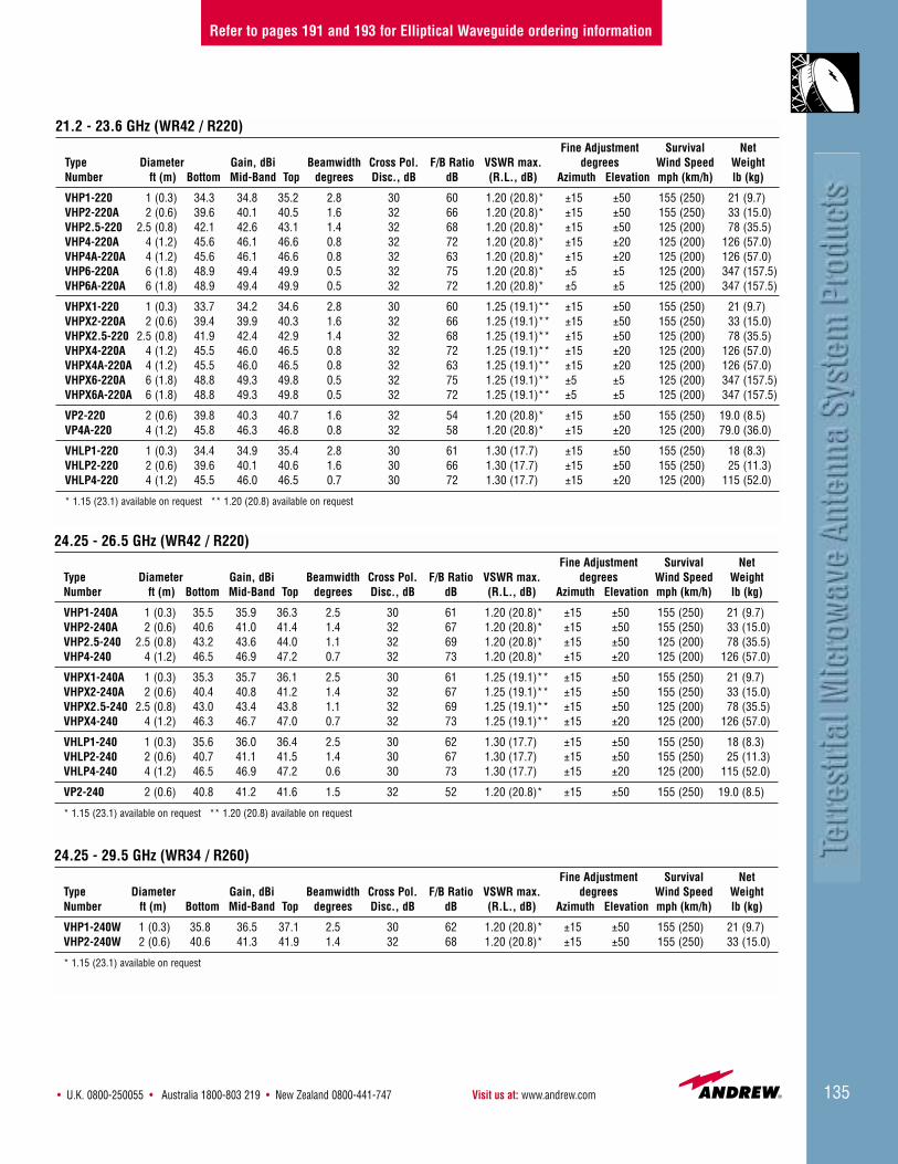
• U.K. 0800-250055 • Australia 1800-803 219 • New Zealand 0800-441-747 Visit us at: www.andrew.com 135
21.2 - 23.6 GHz (WR42 / R220)Fine Adjustment Survival Net
Type Diameter Gain, dBi Beamwidth Cross Pol. F/B Ratio VSWR max. degrees Wind Speed WeightNumber ft (m) Bottom Mid-Band Top degrees Disc., dB dB (R.L., dB) Azimuth Elevation mph (km/h) lb (kg)
VHP1-220 1 (0.3) 34.3 34.8 35.2 2.8 30 60 1.20 (20.8)* ±15 ±50 155 (250) 21 (9.7)VHP2-220A 2 (0.6) 39.6 40.1 40.5 1.6 32 66 1.20 (20.8)* ±15 ±50 155 (250) 33 (15.0)VHP2.5-220 2.5 (0.8) 42.1 42.6 43.1 1.4 32 68 1.20 (20.8)* ±15 ±50 125 (200) 78 (35.5)VHP4-220A 4 (1.2) 45.6 46.1 46.6 0.8 32 72 1.20 (20.8)* ±15 ±20 125 (200) 126 (57.0)VHP4A-220A 4 (1.2) 45.6 46.1 46.6 0.8 32 63 1.20 (20.8)* ±15 ±20 125 (200) 126 (57.0)VHP6-220A 6 (1.8) 48.9 49.4 49.9 0.5 32 75 1.20 (20.8)* ±5 ±5 125 (200) 347 (157.5)VHP6A-220A 6 (1.8) 48.9 49.4 49.9 0.5 32 72 1.20 (20.8)* ±5 ±5 125 (200) 347 (157.5)
VHPX1-220 1 (0.3) 33.7 34.2 34.6 2.8 30 60 1.25 (19.1)** ±15 ±50 155 (250) 21 (9.7)VHPX2-220A 2 (0.6) 39.4 39.9 40.3 1.6 32 66 1.25 (19.1)** ±15 ±50 155 (250) 33 (15.0)VHPX2.5-220 2.5 (0.8) 41.9 42.4 42.9 1.4 32 68 1.25 (19.1)** ±15 ±50 125 (200) 78 (35.5)VHPX4-220A 4 (1.2) 45.5 46.0 46.5 0.8 32 72 1.25 (19.1)** ±15 ±20 125 (200) 126 (57.0)VHPX4A-220A 4 (1.2) 45.5 46.0 46.5 0.8 32 63 1.25 (19.1)** ±15 ±20 125 (200) 126 (57.0)VHPX6-220A 6 (1.8) 48.8 49.3 49.8 0.5 32 75 1.25 (19.1)** ±5 ±5 125 (200) 347 (157.5)VHPX6A-220A 6 (1.8) 48.8 49.3 49.8 0.5 32 72 1.25 (19.1)** ±5 ±5 125 (200) 347 (157.5)
VP2-220 2 (0.6) 39.8 40.3 40.7 1.6 32 54 1.20 (20.8)* ±15 ±50 155 (250) 19.0 (8.5)VP4A-220 4 (1.2) 45.8 46.3 46.8 0.8 32 58 1.20 (20.8)* ±15 ±20 125 (200) 79.0 (36.0)
VHLP1-220 1 (0.3) 34.4 34.9 35.4 2.8 30 61 1.30 (17.7) ±15 ±50 155 (250) 18 (8.3)VHLP2-220 2 (0.6) 39.6 40.1 40.6 1.6 30 66 1.30 (17.7) ±15 ±50 155 (250) 25 (11.3)VHLP4-220 4 (1.2) 45.5 46.0 46.5 0.7 30 72 1.30 (17.7) ±15 ±20 125 (200) 115 (52.0)
* 1.15 (23.1) available on request ** 1.20 (20.8) available on request
24.25 - 26.5 GHz (WR42 / R220)Fine Adjustment Survival Net
Type Diameter Gain, dBi Beamwidth Cross Pol. F/B Ratio VSWR max. degrees Wind Speed WeightNumber ft (m) Bottom Mid-Band Top degrees Disc., dB dB (R.L., dB) Azimuth Elevation mph (km/h) lb (kg)
VHP1-240A 1 (0.3) 35.5 35.9 36.3 2.5 30 61 1.20 (20.8)* ±15 ±50 155 (250) 21 (9.7)VHP2-240A 2 (0.6) 40.6 41.0 41.4 1.4 32 67 1.20 (20.8)* ±15 ±50 155 (250) 33 (15.0)VHP2.5-240 2.5 (0.8) 43.2 43.6 44.0 1.1 32 69 1.20 (20.8)* ±15 ±50 125 (200) 78 (35.5)VHP4-240 4 (1.2) 46.5 46.9 47.2 0.7 32 73 1.20 (20.8)* ±15 ±20 125 (200) 126 (57.0)
VHPX1-240A 1 (0.3) 35.3 35.7 36.1 2.5 30 61 1.25 (19.1)** ±15 ±50 155 (250) 21 (9.7)VHPX2-240A 2 (0.6) 40.4 40.8 41.2 1.4 32 67 1.25 (19.1)** ±15 ±50 155 (250) 33 (15.0)VHPX2.5-240 2.5 (0.8) 43.0 43.4 43.8 1.1 32 69 1.25 (19.1)** ±15 ±50 125 (200) 78 (35.5)VHPX4-240 4 (1.2) 46.3 46.7 47.0 0.7 32 73 1.25 (19.1)** ±15 ±20 125 (200) 126 (57.0)
VHLP1-240 1 (0.3) 35.6 36.0 36.4 2.5 30 62 1.30 (17.7) ±15 ±50 155 (250) 18 (8.3)VHLP2-240 2 (0.6) 40.7 41.1 41.5 1.4 30 67 1.30 (17.7) ±15 ±50 155 (250) 25 (11.3)VHLP4-240 4 (1.2) 46.5 46.9 47.2 0.6 30 73 1.30 (17.7) ±15 ±20 125 (200) 115 (52.0)
VP2-240 2 (0.6) 40.8 41.2 41.6 1.5 32 52 1.20 (20.8)* ±15 ±50 155 (250) 19.0 (8.5)
* 1.15 (23.1) available on request ** 1.20 (20.8) available on request
Refer to pages 191 and 193 for Elliptical Waveguide ordering information
24.25 - 29.5 GHz (WR34 / R260)Fine Adjustment Survival Net
Type Diameter Gain, dBi Beamwidth Cross Pol. F/B Ratio VSWR max. degrees Wind Speed WeightNumber ft (m) Bottom Mid-Band Top degrees Disc., dB dB (R.L., dB) Azimuth Elevation mph (km/h) lb (kg)
VHP1-240W 1 (0.3) 35.8 36.5 37.1 2.5 30 62 1.20 (20.8)* ±15 ±50 155 (250) 21 (9.7)VHP2-240W 2 (0.6) 40.6 41.3 41.9 1.4 32 68 1.20 (20.8)* ±15 ±50 155 (250) 33 (15.0)
* 1.15 (23.1) available on request
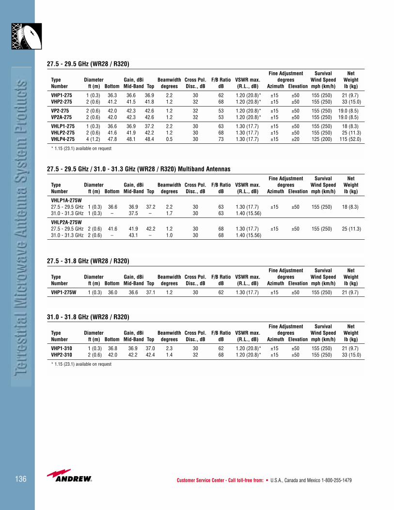
Customer Service Center - Call toll-free from: • U.S.A., Canada and Mexico 1-800-255-1479136
27.5 - 29.5 GHz (WR28 / R320)Fine Adjustment Survival Net
Type Diameter Gain, dBi Beamwidth Cross Pol. F/B Ratio VSWR max. degrees Wind Speed WeightNumber ft (m) Bottom Mid-Band Top degrees Disc., dB dB (R.L., dB) Azimuth Elevation mph (km/h) lb (kg)
VHP1-275 1 (0.3) 36.3 36.6 36.9 2.2 30 62 1.20 (20.8)* ±15 ±50 155 (250) 21 (9.7)VHP2-275 2 (0.6) 41.2 41.5 41.8 1.2 32 68 1.20 (20.8)* ±15 ±50 155 (250) 33 (15.0)
VP2-275 2 (0.6) 42.0 42.3 42.6 1.2 32 53 1.20 (20.8)* ±15 ±50 155 (250) 19.0 (8.5)VP2A-275 2 (0.6) 42.0 42.3 42.6 1.2 32 53 1.20 (20.8)* ±15 ±50 155 (250) 19.0 (8.5)
VHLP1-275 1 (0.3) 36.6 36.9 37.2 2.2 30 63 1.30 (17.7) ±15 ±50 155 (250) 18 (8.3)VHLP2-275 2 (0.6) 41.6 41.9 42.2 1.2 30 68 1.30 (17.7) ±15 ±50 155 (250) 25 (11.3)VHLP4-275 4 (1.2) 47.8 48.1 48.4 0.5 30 73 1.30 (17.7) ±15 ±20 125 (200) 115 (52.0)
* 1.15 (23.1) available on request
27.5 - 29.5 GHz / 31.0 - 31.3 GHz (WR28 / R320) Multiband AntennasFine Adjustment Survival Net
Type Diameter Gain, dBi Beamwidth Cross Pol. F/B Ratio VSWR max. degrees Wind Speed WeightNumber ft (m) Bottom Mid-Band Top degrees Disc., dB dB (R.L., dB) Azimuth Elevation mph (km/h) lb (kg)
VHLP1A-275W27.5 - 29.5 GHz 1 (0.3) 36.6 36.9 37.2 2.2 30 63 1.30 (17.7) ±15 ±50 155 (250) 18 (8.3)31.0 - 31.3 GHz 1 (0.3) – 37.5 – 1.7 30 63 1.40 (15.56)
VHLP2A-275W27.5 - 29.5 GHz 2 (0.6) 41.6 41.9 42.2 1.2 30 68 1.30 (17.7) ±15 ±50 155 (250) 25 (11.3)31.0 - 31.3 GHz 2 (0.6) – 43.1 – 1.0 30 68 1.40 (15.56)
27.5 - 31.8 GHz (WR28 / R320)Fine Adjustment Survival Net
Type Diameter Gain, dBi Beamwidth Cross Pol. F/B Ratio VSWR max. degrees Wind Speed WeightNumber ft (m) Bottom Mid-Band Top degrees Disc., dB dB (R.L., dB) Azimuth Elevation mph (km/h) lb (kg)
VHP1-275W 1 (0.3) 36.0 36.6 37.1 1.2 30 62 1.30 (17.7) ±15 ±50 155 (250) 21 (9.7)
31.0 - 31.8 GHz (WR28 / R320)Fine Adjustment Survival Net
Type Diameter Gain, dBi Beamwidth Cross Pol. F/B Ratio VSWR max. degrees Wind Speed WeightNumber ft (m) Bottom Mid-Band Top degrees Disc., dB dB (R.L., dB) Azimuth Elevation mph (km/h) lb (kg)
VHP1-310 1 (0.3) 36.8 36.9 37.0 2.3 30 62 1.20 (20.8)* ±15 ±50 155 (250) 21 (9.7)VHP2-310 2 (0.6) 42.0 42.2 42.4 1.4 32 68 1.20 (20.8)* ±15 ±50 155 (250) 33 (15.0)
* 1.15 (23.1) available on request
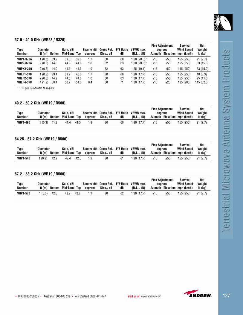
• U.K. 0800-250055 • Australia 1800-803 219 • New Zealand 0800-441-747 Visit us at: www.andrew.com 137
37.0 - 40.0 GHz (WR28 / R320)Fine Adjustment Survival Net
Type Diameter Gain, dBi Beamwidth Cross Pol. F/B Ratio VSWR max. degrees Wind Speed WeightNumber ft (m) Bottom Mid-Band Top degrees Disc., dB dB (R.L., dB) Azimuth Elevation mph (km/h) lb (kg)
VHP1-370A 1 (0.3) 39.2 39.5 39.8 1.7 30 60 1.20 (20.8)* ±15 ±50 155 (250) 21 (9.7)VHP2-370A 2 (0.6) 44.0 44.3 44.6 1.0 32 63 1.20 (20.8)* ±15 ±50 155 (250) 33 (15.0)
VHPX2-370 2 (0.6) 44.0 44.3 44.6 1.0 32 63 1.25 (19.1) ±15 ±50 155 (250) 33 (15.0)
VHLP1-370 1 (0.3) 39.4 39.7 40.0 1.7 30 60 1.30 (17.7) ±15 ±50 155 (250) 18 (8.3)VHLP2-370 2 (0.6) 44.2 44.5 44.8 1.0 30 63 1.30 (17.7) ±15 ±50 155 (250) 25 (11.3)VHLP4-370 4 (1.2) 50.4 50.7 51.0 0.4 30 71 1.30 (17.7) ±15 ±20 125 (200) 115 (52.0)
* 1.15 (23.1) available on request
49.2 - 50.2 GHz (WR19 / R500)Fine Adjustment Survival Net
Type Diameter Gain, dBi Beamwidth Cross Pol. F/B Ratio VSWR max. degrees Wind Speed WeightNumber ft (m) Bottom Mid-Band Top degrees Disc., dB dB (R.L., dB) Azimuth Elevation mph (km/h) lb (kg)
VHP1-490 1 (0.3) 41.3 41.4 41.5 1.3 30 60 1.30 (17.7) ±15 ±50 155 (250) 21 (9.7)
54.25 - 57.2 GHz (WR19 / R500)Fine Adjustment Survival Net
Type Diameter Gain, dBi Beamwidth Cross Pol. F/B Ratio VSWR max. degrees Wind Speed WeightNumber ft (m) Bottom Mid-Band Top degrees Disc., dB dB (R.L., dB) Azimuth Elevation mph (km/h) lb (kg)
VHP1-540 1 (0.3) 42.2 42.4 42.6 1.2 30 61 1.30 (17.7) ±15 ±50 155 (250) 21 (9.7)
57.2 - 58.2 GHz (WR19 / R500)Fine Adjustment Survival Net
Type Diameter Gain, dBi Beamwidth Cross Pol. F/B Ratio VSWR max. degrees Wind Speed WeightNumber ft (m) Bottom Mid-Band Top degrees Disc., dB dB (R.L., dB) Azimuth Elevation mph (km/h) lb (kg)
VHP1-570 1 (0.3) 42.6 42.7 42.8 1.1 30 62 1.30 (17.7) ±15 ±50 155 (250) 21 (9.7)
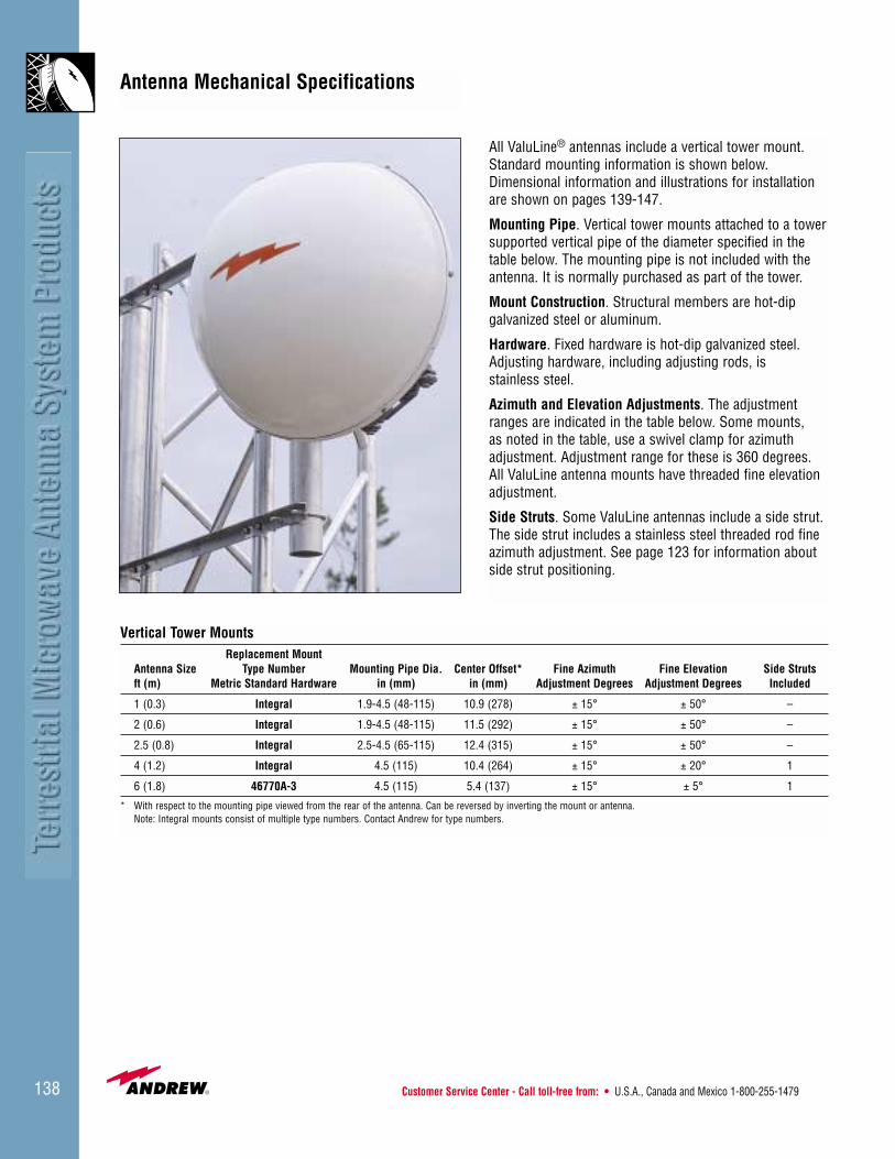
Customer Service Center - Call toll-free from: • U.S.A., Canada and Mexico 1-800-255-1479138
Antenna Mechanical Specifications
Vertical Tower MountsReplacement Mount
Antenna Size Type Number Mounting Pipe Dia. Center Offset* Fine Azimuth Fine Elevation Side Strutsft (m) Metric Standard Hardware in (mm) in (mm) Adjustment Degrees Adjustment Degrees Included
1 (0.3) Integral 1.9-4.5 (48-115) 10.9 (278) ± 15° ± 50° –
2 (0.6) Integral 1.9-4.5 (48-115) 11.5 (292) ± 15° ± 50° –
2.5 (0.8) Integral 2.5-4.5 (65-115) 12.4 (315) ± 15° ± 50° –
4 (1.2) Integral 4.5 (115) 10.4 (264) ± 15° ± 20° 1
6 (1.8) 46770A-3 4.5 (115) 5.4 (137) ± 15° ± 5° 1
* With respect to the mounting pipe viewed from the rear of the antenna. Can be reversed by inverting the mount or antenna.Note: Integral mounts consist of multiple type numbers. Contact Andrew for type numbers.
All ValuLine® antennas include a vertical tower mount.Standard mounting information is shown below.Dimensional information and illustrations for installationare shown on pages 139-147.
Mounting Pipe. Vertical tower mounts attached to a towersupported vertical pipe of the diameter specified in thetable below. The mounting pipe is not included with theantenna. It is normally purchased as part of the tower.
Mount Construction. Structural members are hot-dip galvanized steel or aluminum.
Hardware. Fixed hardware is hot-dip galvanized steel.Adjusting hardware, including adjusting rods, is stainless steel.
Azimuth and Elevation Adjustments. The adjustmentranges are indicated in the table below. Some mounts, as noted in the table, use a swivel clamp for azimuthadjustment. Adjustment range for these is 360 degrees.All ValuLine antenna mounts have threaded fine elevationadjustment.
Side Struts. Some ValuLine antennas include a side strut.The side strut includes a stainless steel threaded rod fineazimuth adjustment. See page 123 for information aboutside strut positioning.
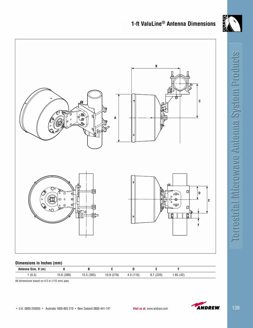
• U.K. 0800-250055 • Australia 1800-803 219 • New Zealand 0800-441-747 Visit us at: www.andrew.com 139
Dimensions in Inches (mm)Antenna Size, ft (m) A B C D E F
1 (0.3) 15.6 (398) 15.5 (393) 10.9 (278) 4.3 (110) 8.7 (220) 1.65 (42)
All dimensions based on 4.5 in (115 mm) pipe.
1-ft ValuLine® Antenna Dimensions
A
B
C
E
D
F
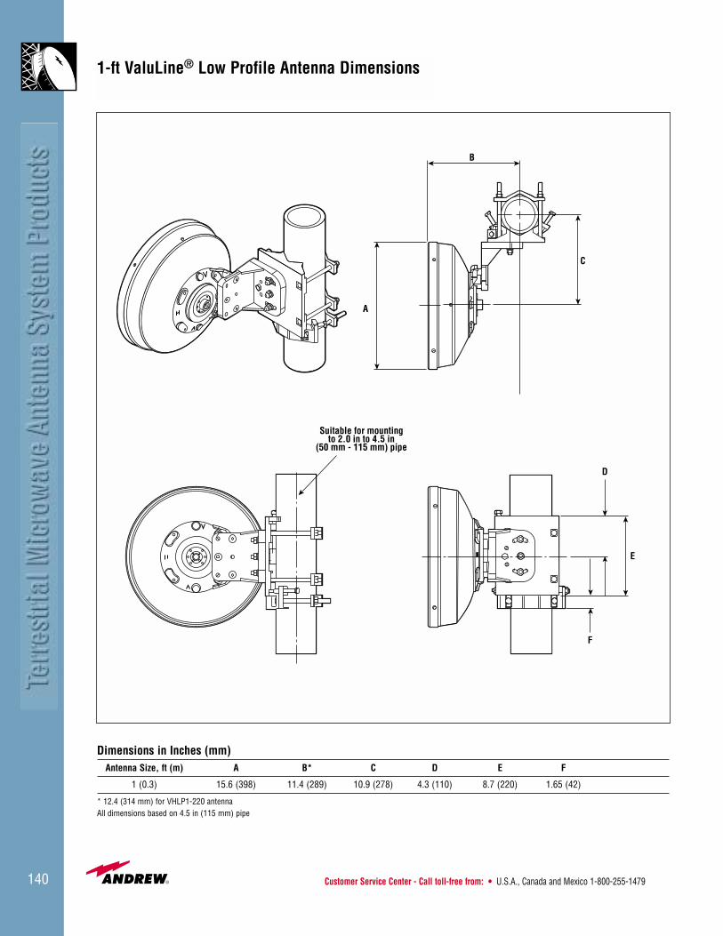
Customer Service Center - Call toll-free from: • U.S.A., Canada and Mexico 1-800-255-1479140
Dimensions in Inches (mm)Antenna Size, ft (m) A B* C D E F
1 (0.3) 15.6 (398) 11.4 (289) 10.9 (278) 4.3 (110) 8.7 (220) 1.65 (42)
* 12.4 (314 mm) for VHLP1-220 antennaAll dimensions based on 4.5 in (115 mm) pipe
1-ft ValuLine® Low Profile Antenna Dimensions
D
E
Suitable for mountingto 2.0 in to 4.5 in
(50 mm - 115 mm) pipe
F
B
C
A
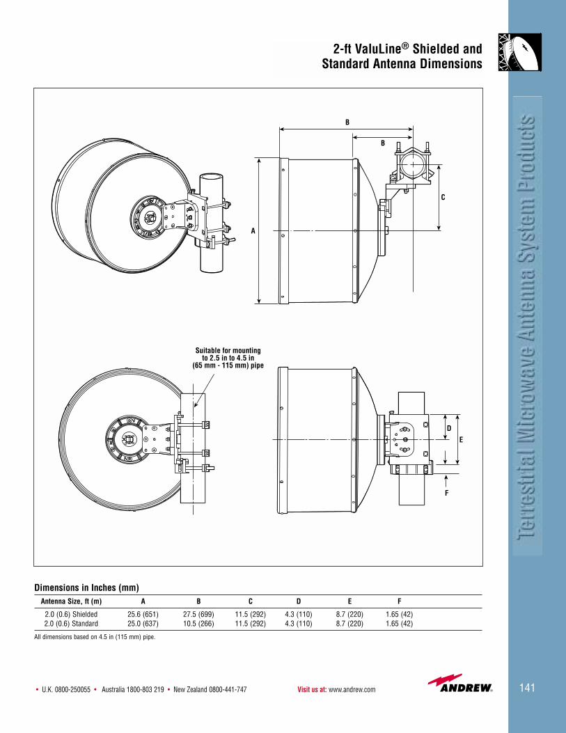
• U.K. 0800-250055 • Australia 1800-803 219 • New Zealand 0800-441-747 Visit us at: www.andrew.com 141
Dimensions in Inches (mm)Antenna Size, ft (m) A B C D E F
2.0 (0.6) Shielded 25.6 (651) 27.5 (699) 11.5 (292) 4.3 (110) 8.7 (220) 1.65 (42)2.0 (0.6) Standard 25.0 (637) 10.5 (266) 11.5 (292) 4.3 (110) 8.7 (220) 1.65 (42)
All dimensions based on 4.5 in (115 mm) pipe.
2-ft ValuLine® Shielded and Standard Antenna Dimensions
Suitable for mountingto 2.5 in to 4.5 in
(65 mm - 115 mm) pipe
C
B
F
A
ED
B
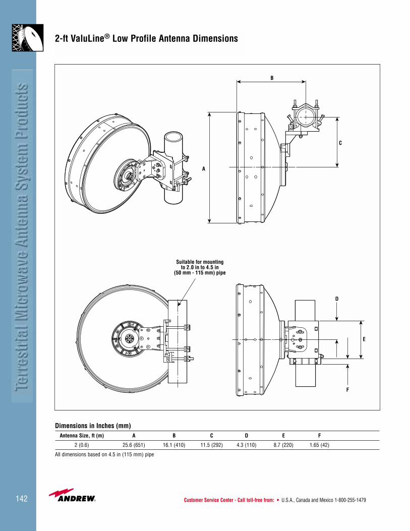
Customer Service Center - Call toll-free from: • U.S.A., Canada and Mexico 1-800-255-1479142
Dimensions in Inches (mm)Antenna Size, ft (m) A B C D E F
2 (0.6) 25.6 (651) 16.1 (410) 11.5 (292) 4.3 (110) 8.7 (220) 1.65 (42)
All dimensions based on 4.5 in (115 mm) pipe
2-ft ValuLine® Low Profile Antenna Dimensions
Suitable for mountingto 2.0 in to 4.5 in
(50 mm - 115 mm) pipe
D
E
F
C
B
A
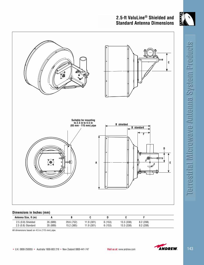
• U.K. 0800-250055 • Australia 1800-803 219 • New Zealand 0800-441-747 Visit us at: www.andrew.com 143
Dimensions in Inches (mm)Antenna Size, ft (m) A B C D E F
2.5 (0.8) Shielded 35 (889) 29.6 (752) 11.9 (301) 6 (153) 13.3 (338) 8.2 (208)2.5 (0.8) Standard 35 (889) 15.2 (385) 11.9 (301) 6 (153) 13.3 (338) 8.2 (208)
All dimensions based on 4.5 in (115 mm) pipe.
2.5-ft ValuLine® Shielded and Standard Antenna Dimensions
C
A
B
F
Suitable for mountingto 2.5 in to 4.5 in
(65 mm - 115 mm) pipeB
E
D
shieldedstandard
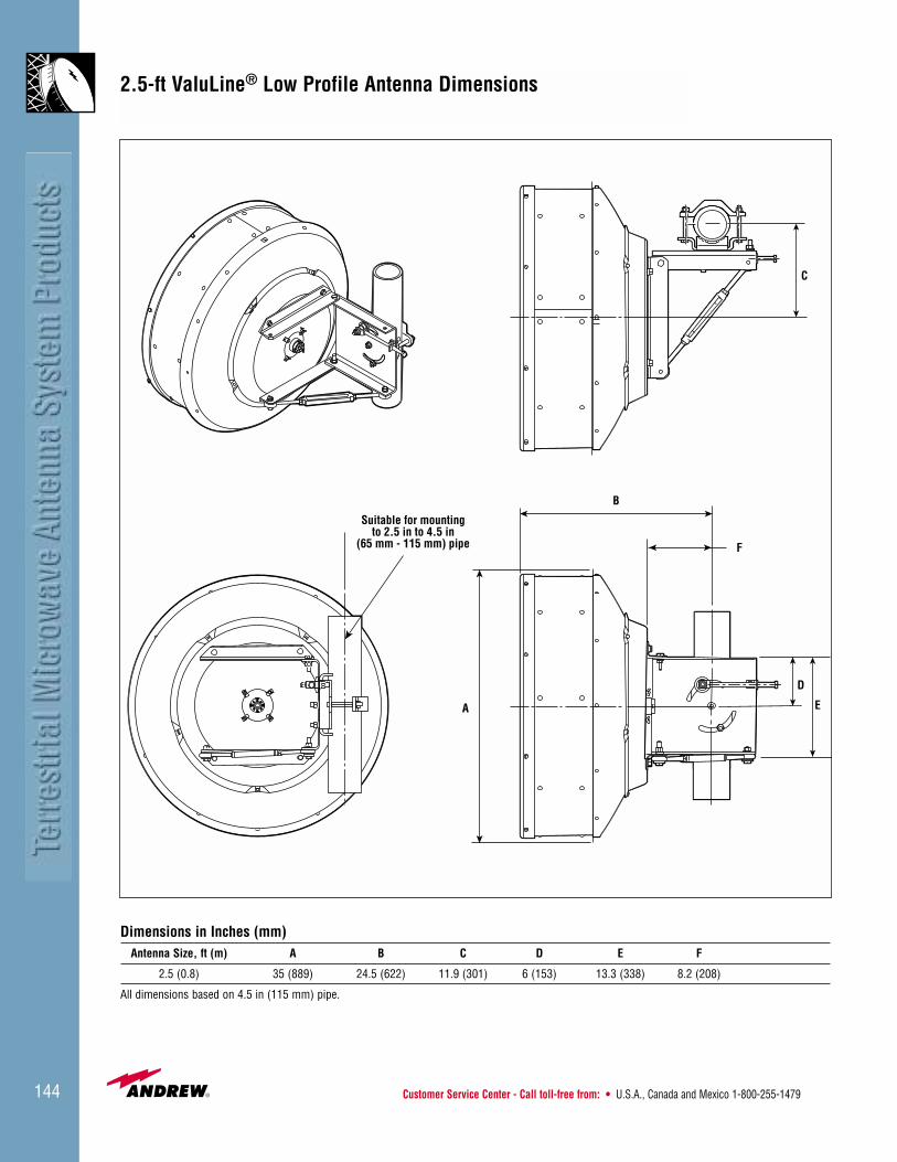
Customer Service Center - Call toll-free from: • U.S.A., Canada and Mexico 1-800-255-1479144
Dimensions in Inches (mm)Antenna Size, ft (m) A B C D E F
2.5 (0.8) 35 (889) 24.5 (622) 11.9 (301) 6 (153) 13.3 (338) 8.2 (208)
All dimensions based on 4.5 in (115 mm) pipe.
2.5-ft ValuLine® Low Profile Antenna Dimensions
C
A
B
F
Suitable for mountingto 2.5 in to 4.5 in
(65 mm - 115 mm) pipe
E
D
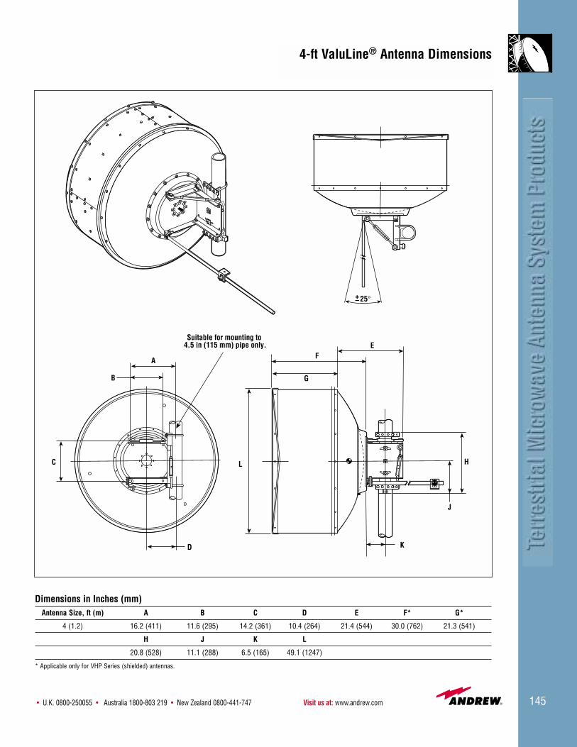
• U.K. 0800-250055 • Australia 1800-803 219 • New Zealand 0800-441-747 Visit us at: www.andrew.com 145
Dimensions in Inches (mm)Antenna Size, ft (m) A B C D E F* G*
4 (1.2) 16.2 (411) 11.6 (295) 14.2 (361) 10.4 (264) 21.4 (544) 30.0 (762) 21.3 (541)
H J K L
20.8 (528) 11.1 (288) 6.5 (165) 49.1 (1247)
* Applicable only for VHP Series (shielded) antennas.
4-ft ValuLine® Antenna Dimensions
C
B
A
D
L
G
F
H
J
K
E
25°+–
Suitable for mounting to 4.5 in (115 mm) pipe only.
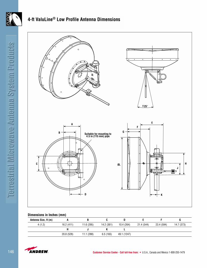
Customer Service Center - Call toll-free from: • U.S.A., Canada and Mexico 1-800-255-1479146
Dimensions in Inches (mm)Antenna Size, ft (m) A B C D E F G
4 (1.2) 16.2 (411) 11.6 (295) 14.2 (361) 10.4 (264) 21.4 (544) 23.4 (594) 14.7 (373)
H J K L
20.8 (528) 11.1 (288) 6.5 (165) 49.1 (1247)
25°+–
ØL
G
F
H
J
K
E
C
B
A
D
Suitable for mounting to4.5 in (115 mm) pipe
4-ft ValuLine® Low Profile Antenna Dimensions
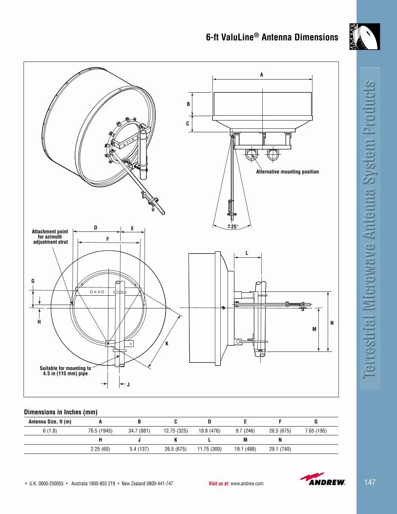
• U.K. 0800-250055 • Australia 1800-803 219 • New Zealand 0800-441-747 Visit us at: www.andrew.com 147
Dimensions in Inches (mm)Antenna Size, ft (m) A B C D E F G
6 (1.8) 76.5 (1945) 34.7 (881) 12.75 (325) 18.8 (476) 9.7 (246) 26.5 (675) 7.65 (195)
H J K L M N
2.25 (60) 5.4 (137) 26.5 (675) 11.75 (300) 19.1 (488) 29.1 (740)
6-ft ValuLine® Antenna Dimensions
25°+–
Suitable for mounting to4.5 in (115 mm) pipe
B
C
A
L
MN
J
K
F
D
G
H
E
Alternative mounting position
Attachment point for azimuth
adjustment strut
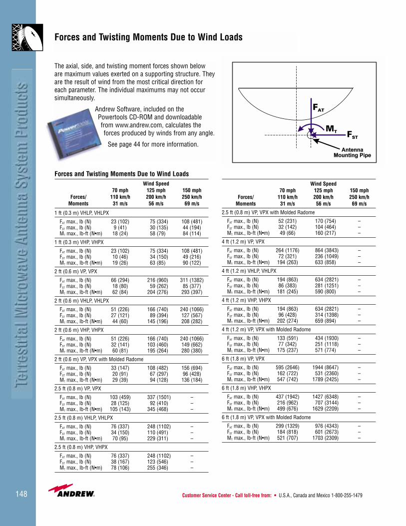
Customer Service Center - Call toll-free from: • U.S.A., Canada and Mexico 1-800-255-1479148
The axial, side, and twisting moment forces shown beloware maximum values exerted on a supporting structure. Theyare the result of wind from the most critical direction foreach parameter. The individual maximums may not occursimultaneously.
Andrew Software, included on thePowertools CD-ROM and downloadablefrom www.andrew.com, calculates theforces produced by winds from any angle.
See page 44 for more information.
Forces and Twisting Moments Due to Wind LoadsWind Speed
70 mph 125 mph 150 mphForces/ 110 km/h 200 km/h 250 km/h
Moments 31 m/s 56 m/s 69 m/s
1 ft (0.3 m) VHLP, VHLPX
FAT max., lb (N) 23 (102) 75 (334) 108 (481)FST max., lb (N) 9 (41) 30 (135) 44 (194)MT max., lb-ft (N•m) 18 (24) 58 (79) 84 (114)
1 ft (0.3 m) VHP, VHPX
FAT max., lb (N) 23 (102) 75 (334) 108 (481)FST max., lb (N) 10 (46) 34 (150) 49 (216)MT max., lb-ft (N•m) 19 (26) 63 (85) 90 (122)
2 ft (0.6 m) VP, VPX
FAT max., lb (N) 66 (294) 216 (960) 311 (1382)FST max., lb (N) 18 (80) 59 (262) 85 (377)MT max., lb-ft (N•m) 62 (84) 204 (276) 293 (397)
2 ft (0.6 m) VHLP, VHLPX
FAT max., lb (N) 51 (226) 166 (740) 240 (1066)FST max., lb (N) 27 (121) 89 (394) 127 (567)MT max., lb-ft (N•m) 44 (60) 145 (196) 208 (282)
2 ft (0.6 m) VHP, VHPX
FAT max., lb (N) 51 (226) 166 (740) 240 (1066)FST max., lb (N) 32 (141) 103 (460) 149 (662)MT max., lb-ft (N•m) 60 (81) 195 (264) 280 (380)
2 ft (0.6 m) VP, VPX with Molded Radome
FAT max., lb (N) 33 (147) 108 (482) 156 (694)FST max., lb (N) 20 (91) 67 (297) 96 (428)MT max., lb-ft (N•m) 29 (39) 94 (128) 136 (184)
2.5 ft (0.8 m) VP, VPX
FAT max., lb (N) 103 (459) 337 (1501) –FST max., lb (N) 28 (125) 92 (410) –MT max., lb-ft (N•m) 105 (143) 345 (468) –
2.5 ft (0.8 m) VHLP, VHLPX
FAT max., lb (N) 76 (337) 248 (1102) –FST max., lb (N) 34 (150) 110 (491) –MT max., lb-ft (N•m) 70 (95) 229 (311) –
2.5 ft (0.8 m) VHP, VHPX
FAT max., lb (N) 76 (337) 248 (1102) –FST max., lb (N) 38 (167) 123 (546) –MT max., lb-ft (N•m) 78 (106) 255 (346) –
Forces and Twisting Moments Due to Wind Loads
Wind Speed70 mph 125 mph 150 mph
Forces/ 110 km/h 200 km/h 250 km/hMoments 31 m/s 56 m/s 69 m/s
2.5 ft (0.8 m) VP, VPX with Molded Radome
FAT max., lb (N) 52 (231) 170 (754) –FST max., lb (N) 32 (142) 104 (464) –MT max., lb-ft (N•m) 49 (66) 160 (217) –
4 ft (1.2 m) VP, VPX
FAT max., lb (N) 264 (1176) 864 (3843) –FST max., lb (N) 72 (321) 236 (1049) –MT max., lb-ft (N•m) 194 (263) 633 (858) –
4 ft (1.2 m) VHLP, VHLPX
FAT max., lb (N) 194 (863) 634 (2821) –FST max., lb (N) 86 (383) 281 (1251) –MT max., lb-ft (N•m) 181 (245) 590 (800) –
4 ft (1.2 m) VHP, VHPX
FAT max., lb (N) 194 (863) 634 (2821) –FST max., lb (N) 96 (428) 314 (1398) –MT max., lb-ft (N•m) 202 (274) 659 (894) –
4 ft (1.2 m) VP, VPX with Molded Radome
FAT max., lb (N) 133 (591) 434 (1930) –FST max., lb (N) 77 (342) 251 (1118) –MT max., lb-ft (N•m) 175 (237) 571 (774) –
6 ft (1.8 m) VP, VPX
FAT max., lb (N) 595 (2646) 1944 (8647) –FST max., lb (N) 162 (722) 531 (2360) –MT max., lb-ft (N•m) 547 (742) 1789 (2425) –
6 ft (1.8 m) VHP, VHPX
FAT max., lb (N) 437 (1942) 1427 (6348) –FST max., lb (N) 216 (962) 707 (3144) –MT max., lb-ft (N•m) 499 (676) 1629 (2209) –
6 ft (1.8 m) VP, VPX with Molded Radome
FAT max., lb (N) 299 (1329) 976 (4343) –FST max., lb (N) 184 (818) 601 (2673) –MT max., lb-ft (N•m) 521 (707) 1703 (2309) –
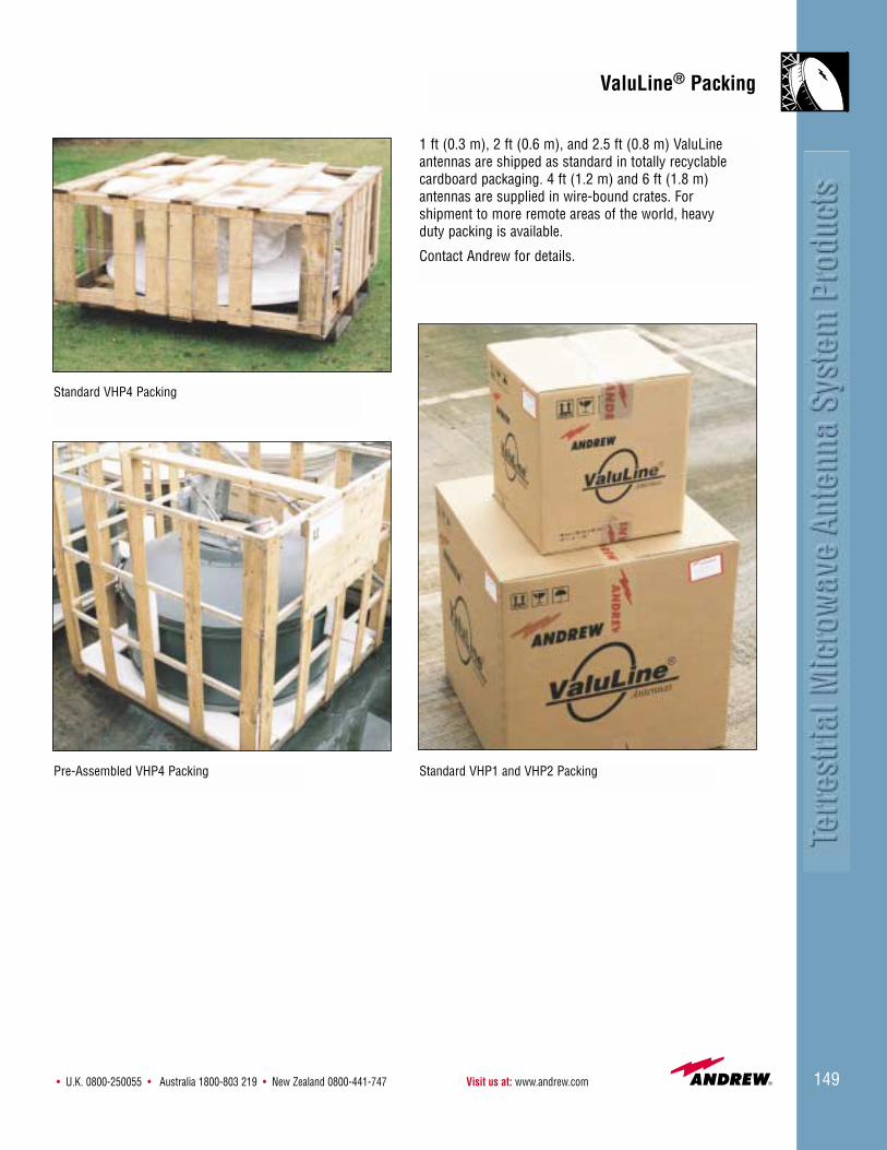
• U.K. 0800-250055 • Australia 1800-803 219 • New Zealand 0800-441-747 Visit us at: www.andrew.com 149
1 ft (0.3 m), 2 ft (0.6 m), and 2.5 ft (0.8 m) ValuLineantennas are shipped as standard in totally recyclablecardboard packaging. 4 ft (1.2 m) and 6 ft (1.8 m) antennas are supplied in wire-bound crates. For shipment to more remote areas of the world, heavy duty packing is available.
Contact Andrew for details.
ValuLine® Packing
Standard VHP4 Packing
Standard VHP1 and VHP2 PackingPre-Assembled VHP4 Packing
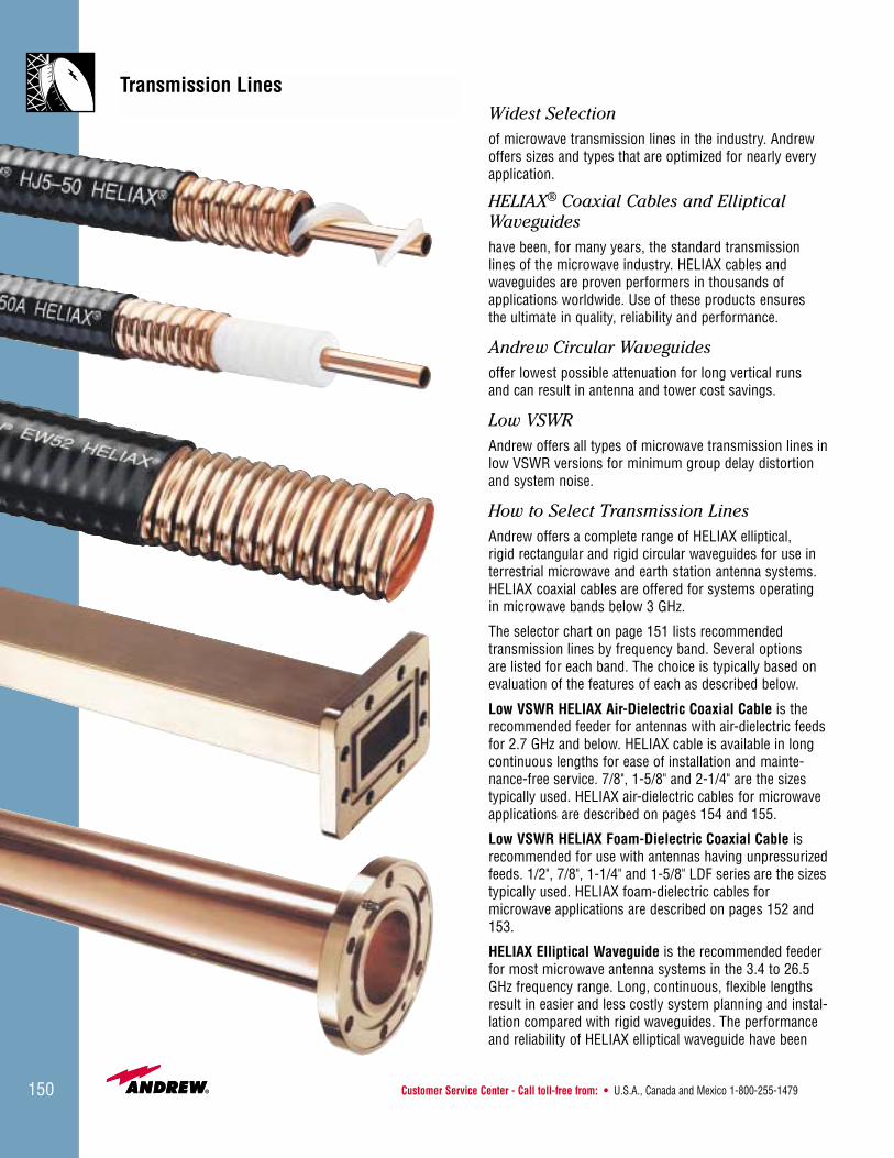
Customer Service Center - Call toll-free from: • U.S.A., Canada and Mexico 1-800-255-1479
Widest Selectionof microwave transmission lines in the industry. Andrewoffers sizes and types that are optimized for nearly everyapplication.
HELIAX® Coaxial Cables and EllipticalWaveguideshave been, for many years, the standard transmissionlines of the microwave industry. HELIAX cables and waveguides are proven performers in thousands of applications worldwide. Use of these products ensures the ultimate in quality, reliability and performance.
Andrew Circular Waveguidesoffer lowest possible attenuation for long vertical runs and can result in antenna and tower cost savings.
Low VSWRAndrew offers all types of microwave transmission lines inlow VSWR versions for minimum group delay distortionand system noise.
How to Select Transmission LinesAndrew offers a complete range of HELIAX elliptical, rigid rectangular and rigid circular waveguides for use interrestrial microwave and earth station antenna systems.HELIAX coaxial cables are offered for systems operatingin microwave bands below 3 GHz.
The selector chart on page 151 lists recommended transmission lines by frequency band. Several options are listed for each band. The choice is typically based onevaluation of the features of each as described below.
Low VSWR HELIAX Air-Dielectric Coaxial Cable is the recommended feeder for antennas with air-dielectric feedsfor 2.7 GHz and below. HELIAX cable is available in longcontinuous lengths for ease of installation and mainte-nance-free service. 7/8", 1-5/8" and 2-1/4" are the sizestypically used. HELIAX air-dielectric cables for microwaveapplications are described on pages 154 and 155.
Low VSWR HELIAX Foam-Dielectric Coaxial Cable is recommended for use with antennas having unpressurizedfeeds. 1/2", 7/8", 1-1/4" and 1-5/8" LDF series are the sizestypically used. HELIAX foam-dielectric cables formicrowave applications are described on pages 152 and153.
HELIAX Elliptical Waveguide is the recommended feederfor most microwave antenna systems in the 3.4 to 26.5GHz frequency range. Long, continuous, flexible lengthsresult in easier and less costly system planning and instal-lation compared with rigid waveguides. The performanceand reliability of HELIAX elliptical waveguide have been
Transmission Lines
150
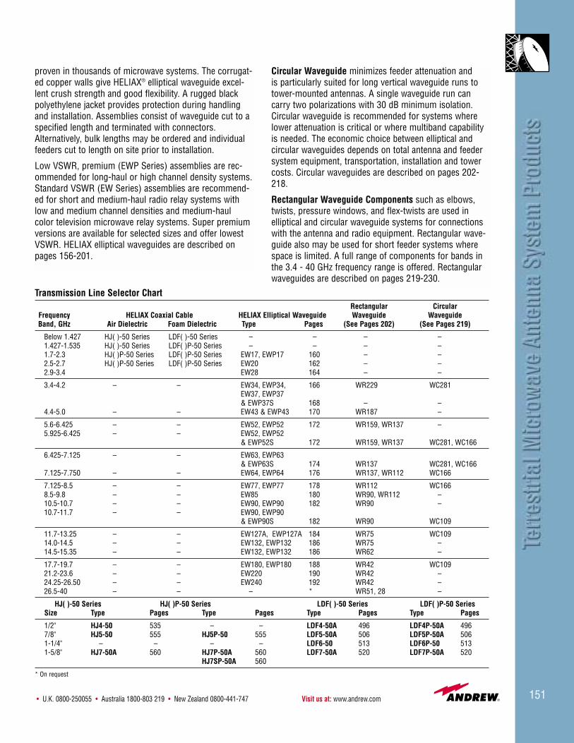
• U.K. 0800-250055 • Australia 1800-803 219 • New Zealand 0800-441-747 Visit us at: www.andrew.com 151
Transmission Line Selector ChartRectangular Circular
Frequency HELIAX Coaxial Cable HELIAX Elliptical Waveguide Waveguide WaveguideBand, GHz Air Dielectric Foam Dielectric Type Pages (See Pages 202) (See Pages 219)
Below 1.427 HJ( )-50 Series LDF( )-50 Series – – – –1.427-1.535 HJ( )-50 Series LDF( )P-50 Series – – – –1.7-2.3 HJ( )P-50 Series LDF( )P-50 Series EW17, EWP17 160 – –2.5-2.7 HJ( )P-50 Series LDF( )P-50 Series EW20 162 – –2.9-3.4 EW28 164 – –
3.4-4.2 – – EW34, EWP34, 166 WR229 WC281EW37, EWP37 & EWP37S 168 – –
4.4-5.0 – – EW43 & EWP43 170 WR187 –
5.6-6.425 – – EW52, EWP52 172 WR159, WR137 –5.925-6.425 – – EW52, EWP52
& EWP52S 172 WR159, WR137 WC281, WC166
6.425-7.125 – – EW63, EWP63 & EWP63S 174 WR137 WC281, WC166
7.125-7.750 – – EW64, EWP64 176 WR137, WR112 WC166
7.125-8.5 – – EW77, EWP77 178 WR112 WC1668.5-9.8 – – EW85 180 WR90, WR112 –10.5-10.7 – – EW90, EWP90 182 WR90 –10.7-11.7 – – EW90, EWP90
& EWP90S 182 WR90 WC109
11.7-13.25 – – EW127A, EWP127A 184 WR75 WC10914.0-14.5 – – EW132, EWP132 186 WR75 –14.5-15.35 – – EW132, EWP132 186 WR62 –
17.7-19.7 – – EW180, EWP180 188 WR42 WC10921.2-23.6 – – EW220 190 WR42 –24.25-26.50 – – EW240 192 WR42 –26.5-40 – – – * WR51, 28 –
HJ( )-50 Series HJ( )P-50 Series LDF( )-50 Series LDF( )P-50 SeriesSize Type Pages Type Pages Type Pages Type Pages
1/2" HJ4-50 535 – – LDF4-50A 496 LDF4P-50A 4967/8" HJ5-50 555 HJ5P-50 555 LDF5-50A 506 LDF5P-50A 5061-1/4" – – – – LDF6-50 513 LDF6P-50 5131-5/8" HJ7-50A 560 HJ7P-50A 560 LDF7-50A 520 LDF7P-50A 520
HJ7SP-50A 560
* On request
proven in thousands of microwave systems. The corrugat-ed copper walls give HELIAX® elliptical waveguide excel-lent crush strength and good flexibility. A rugged blackpolyethylene jacket provides protection during handlingand installation. Assemblies consist of waveguide cut to aspecified length and terminated with connectors.Alternatively, bulk lengths may be ordered and individualfeeders cut to length on site prior to installation.
Low VSWR, premium (EWP Series) assemblies are rec-ommended for long-haul or high channel density systems.Standard VSWR (EW Series) assemblies are recommend-ed for short and medium-haul radio relay systems withlow and medium channel densities and medium-haul color television microwave relay systems. Super premium versions are available for selected sizes and offer lowestVSWR. HELIAX elliptical waveguides are described onpages 156-201.
Circular Waveguide minimizes feeder attenuation andis particularly suited for long vertical waveguide runs totower-mounted antennas. A single waveguide run cancarry two polarizations with 30 dB minimum isolation.Circular waveguide is recommended for systems wherelower attenuation is critical or where multiband capabilityis needed. The economic choice between elliptical and circular waveguides depends on total antenna and feedersystem equipment, transportation, installation and towercosts. Circular waveguides are described on pages 202-218.
Rectangular Waveguide Components such as elbows,twists, pressure windows, and flex-twists are used inelliptical and circular waveguide systems for connectionswith the antenna and radio equipment. Rectangular wave-guide also may be used for short feeder systems wherespace is limited. A full range of components for bands inthe 3.4 - 40 GHz frequency range is offered. Rectangularwaveguides are described on pages 219-230.
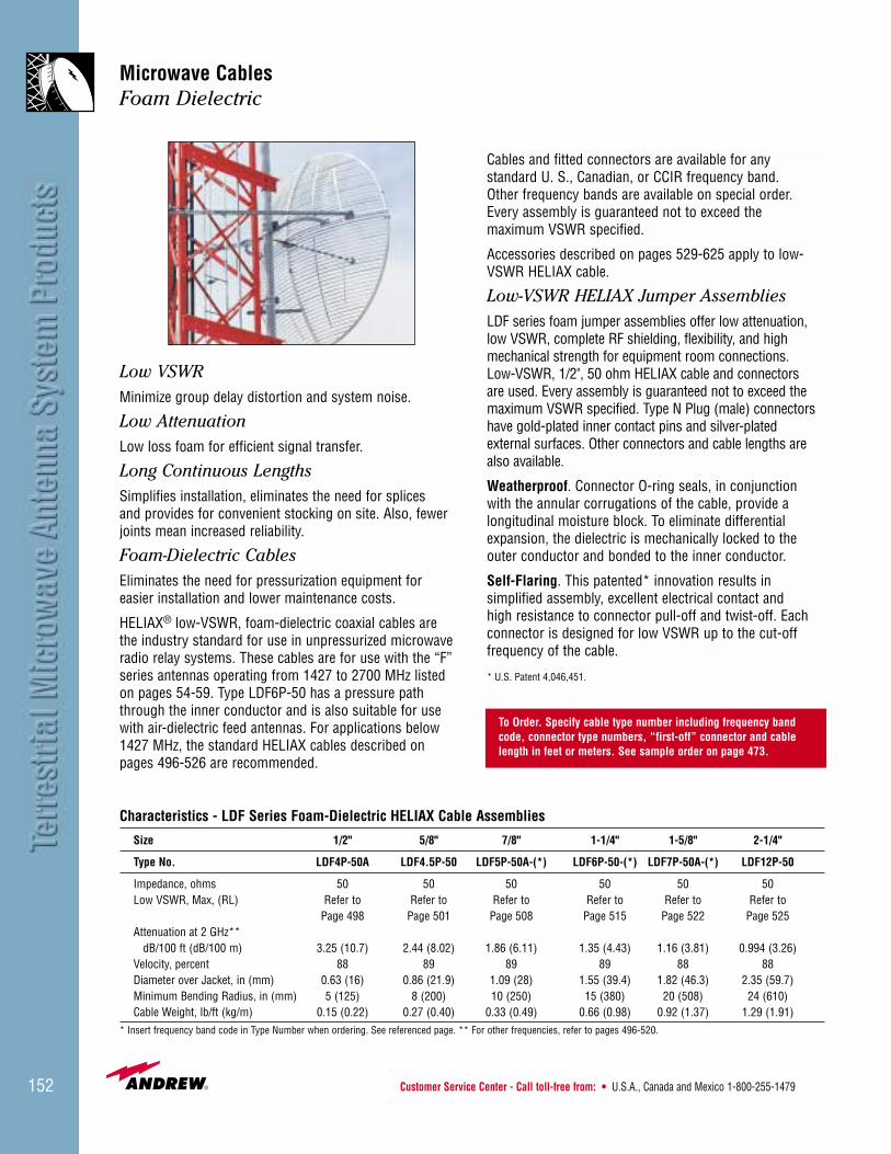
Customer Service Center - Call toll-free from: • U.S.A., Canada and Mexico 1-800-255-1479152
To Order. Specify cable type number including frequency bandcode, connector type numbers, “first-off” connector and cablelength in feet or meters. See sample order on page 473.
Characteristics - LDF Series Foam-Dielectric HELIAX Cable Assemblies
Size 1/2" 5/8" 7/8" 1-1/4" 1-5/8" 2-1/4"
Type No. LDF4P-50A LDF4.5P-50 LDF5P-50A-(*) LDF6P-50-(*) LDF7P-50A-(*) LDF12P-50
Impedance, ohms 50 50 50 50 50 50Low VSWR, Max, (RL) Refer to Refer to Refer to Refer to Refer to Refer to
Page 498 Page 501 Page 508 Page 515 Page 522 Page 525Attenuation at 2 GHz**
dB/100 ft (dB/100 m) 3.25 (10.7) 2.44 (8.02) 1.86 (6.11) 1.35 (4.43) 1.16 (3.81) 0.994 (3.26)Velocity, percent 88 89 89 89 88 88Diameter over Jacket, in (mm) 0.63 (16) 0.86 (21.9) 1.09 (28) 1.55 (39.4) 1.82 (46.3) 2.35 (59.7)Minimum Bending Radius, in (mm) 5 (125) 8 (200) 10 (250) 15 (380) 20 (508) 24 (610)Cable Weight, lb/ft (kg/m) 0.15 (0.22) 0.27 (0.40) 0.33 (0.49) 0.66 (0.98) 0.92 (1.37) 1.29 (1.91)
* Insert frequency band code in Type Number when ordering. See referenced page. ** For other frequencies, refer to pages 496-520.
Low VSWRMinimize group delay distortion and system noise.
Low AttenuationLow loss foam for efficient signal transfer.
Long Continuous LengthsSimplifies installation, eliminates the need for splices and provides for convenient stocking on site. Also, fewerjoints mean increased reliability.
Foam-Dielectric CablesEliminates the need for pressurization equipment for easier installation and lower maintenance costs.
HELIAX® low-VSWR, foam-dielectric coaxial cables arethe industry standard for use in unpressurized microwaveradio relay systems. These cables are for use with the “F”series antennas operating from 1427 to 2700 MHz listedon pages 54-59. Type LDF6P-50 has a pressure paththrough the inner conductor and is also suitable for usewith air-dielectric feed antennas. For applications below1427 MHz, the standard HELIAX cables described onpages 496-526 are recommended.
Microwave CablesFoam Dielectric
Cables and fitted connectors are available for any standard U. S., Canadian, or CCIR frequency band. Other frequency bands are available on special order.Every assembly is guaranteed not to exceed the maximum VSWR specified.
Accessories described on pages 529-625 apply to low-VSWR HELIAX cable.
Low-VSWR HELIAX Jumper AssembliesLDF series foam jumper assemblies offer low attenuation,low VSWR, complete RF shielding, flexibility, and highmechanical strength for equipment room connections. Low-VSWR, 1/2", 50 ohm HELIAX cable and connectors are used. Every assembly is guaranteed not to exceed themaximum VSWR specified. Type N Plug (male) connectorshave gold-plated inner contact pins and silver-plated external surfaces. Other connectors and cable lengths arealso available.
Weatherproof. Connector O-ring seals, in conjunctionwith the annular corrugations of the cable, provide a longitudinal moisture block. To eliminate differentialexpansion, the dielectric is mechanically locked to theouter conductor and bonded to the inner conductor.
Self-Flaring. This patented* innovation results in simplified assembly, excellent electrical contact and high resistance to connector pull-off and twist-off. Eachconnector is designed for low VSWR up to the cut-off frequency of the cable.
* U.S. Patent 4,046,451.
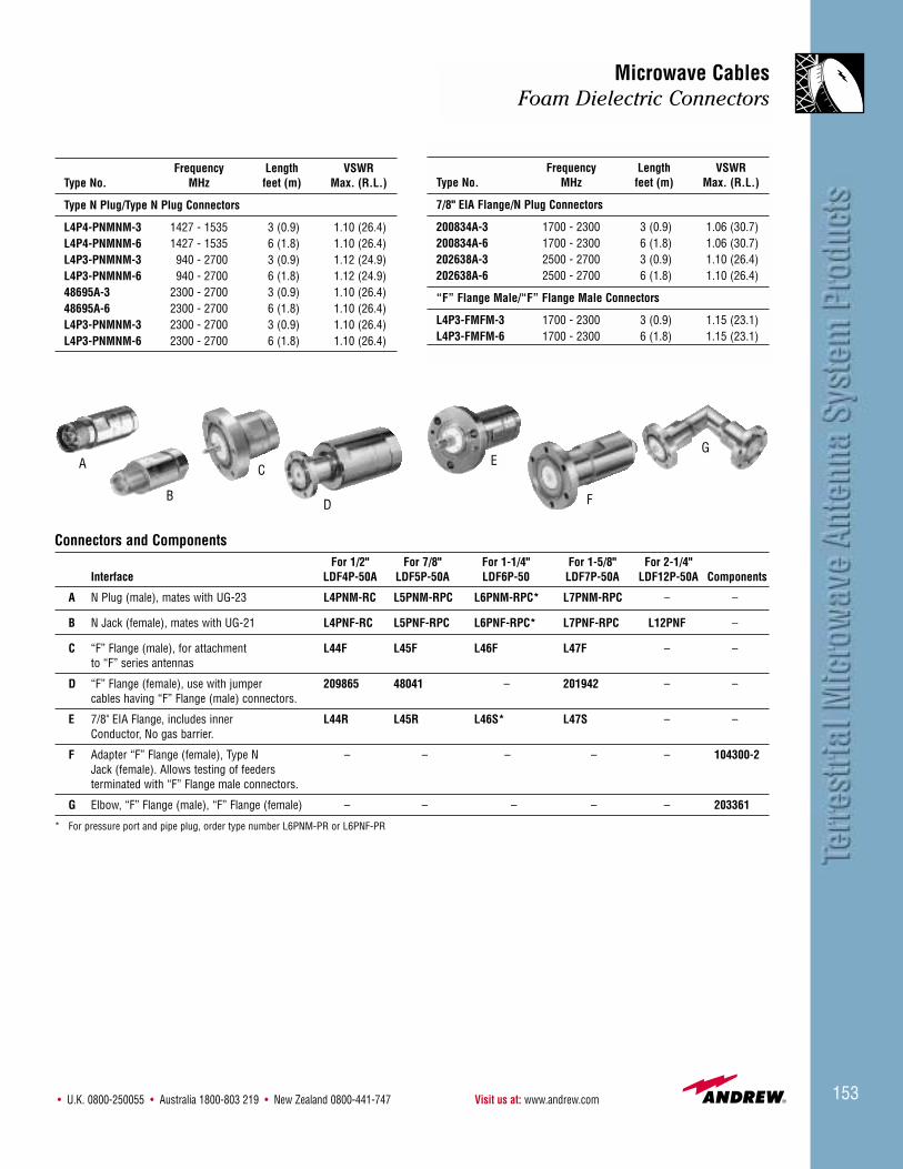
• U.K. 0800-250055 • Australia 1800-803 219 • New Zealand 0800-441-747 Visit us at: www.andrew.com 153
Frequency Length VSWRType No. MHz feet (m) Max. (R.L.)
Type N Plug/Type N Plug Connectors
L4P4-PNMNM-3 1427 - 1535 3 (0.9) 1.10 (26.4)L4P4-PNMNM-6 1427 - 1535 6 (1.8) 1.10 (26.4)L4P3-PNMNM-3 940 - 2700 3 (0.9) 1.12 (24.9)L4P3-PNMNM-6 940 - 2700 6 (1.8) 1.12 (24.9)48695A-3 2300 - 2700 3 (0.9) 1.10 (26.4)48695A-6 2300 - 2700 6 (1.8) 1.10 (26.4)L4P3-PNMNM-3 2300 - 2700 3 (0.9) 1.10 (26.4)L4P3-PNMNM-6 2300 - 2700 6 (1.8) 1.10 (26.4)
Connectors and ComponentsFor 1/2" For 7/8" For 1-1/4" For 1-5/8" For 2-1/4"
Interface LDF4P-50A LDF5P-50A LDF6P-50 LDF7P-50A LDF12P-50A Components
A N Plug (male), mates with UG-23 L4PNM-RC L5PNM-RPC L6PNM-RPC* L7PNM-RPC – –
B N Jack (female), mates with UG-21 L4PNF-RC L5PNF-RPC L6PNF-RPC* L7PNF-RPC L12PNF –
C “F” Flange (male), for attachment L44F L45F L46F L47F – –to “F” series antennas
D “F” Flange (female), use with jumper 209865 48041 – 201942 – –cables having “F” Flange (male) connectors.
E 7/8" EIA Flange, includes inner L44R L45R L46S* L47S – –Conductor, No gas barrier.
F Adapter “F” Flange (female), Type N – – – – – 104300-2Jack (female). Allows testing of feedersterminated with “F” Flange male connectors.
G Elbow, “F” Flange (male), “F” Flange (female) – – – – – 203361
* For pressure port and pipe plug, order type number L6PNM-PR or L6PNF-PR
Frequency Length VSWRType No. MHz feet (m) Max. (R.L.)
7/8" EIA Flange/N Plug Connectors
200834A-3 1700 - 2300 3 (0.9) 1.06 (30.7)200834A-6 1700 - 2300 6 (1.8) 1.06 (30.7)202638A-3 2500 - 2700 3 (0.9) 1.10 (26.4)202638A-6 2500 - 2700 6 (1.8) 1.10 (26.4)
“F” Flange Male/“F” Flange Male Connectors
L4P3-FMFM-3 1700 - 2300 3 (0.9) 1.15 (23.1)L4P3-FMFM-6 1700 - 2300 6 (1.8) 1.15 (23.1)
A
B
C
D
E
F
G
Microwave CablesFoam Dielectric Connectors
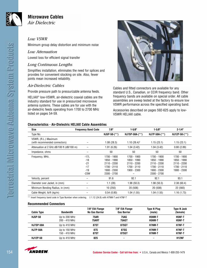
Customer Service Center - Call toll-free from: • U.S.A., Canada and Mexico 1-800-255-1479154
Characteristics - Air-Dielectric HELIAX Cable AssembliesSize Frequency Band Code 7/8" 1-5/8" 1-5/8" 2-1/4"
Type No. HJ5P-50-(**) HJ7SP-50A-(**) HJ7P-50A-(**) HJ12P-50-(**)
VSWR, (R.L.) Maximum(with recommended connectors) – 1.08 (28.3) 1.10 (26.4)† 1.15 (23.1) 1.15 (23.1)
Attenuation at 2 GHz dB/100 ft (dB/100 m) – 1.91 (6.26) 1.04 (3.42) 1.04 (3.42) 0.80 (2.89)
Impedance, ohms – 50 50 50 50
Frequency, MHz, -17L 1700 - 1900 1700 - 1900 1700 - 1900 1700 - 1900-18 1850 - 1990 1850 - 1990 1850 - 1990 1850 - 1990-21 2110 - 2200 2110 - 2200 2110 - 2200 2110 - 2200-17 1700 - 2110 1700 - 2110 1700 - 2110 1700 - 2110-19 1900 - 2300 1900 - 2300 1900 - 2300 1900 - 2300
-23W 2300 - 2700 – 2300 - 2700 –
Velocity, percent – 91.6 92.1 92.1 93.1
Diameter over Jacket, in (mm) – 1.1 (28) 1.98 (50.3) 1.98 (50.3) 2.38 (60.4)
Minimum Bending Radius, in (mm) – 10 (250) 20 (508) 20 (508) 22 (560)
Cable Weight, lb/ft (kg/m) – 0.54 (0.80) 1.04 (1.55) 1.04 (1.55) 1.16 (1.73)
** Insert frequency band code in Type Number when ordering. † 1.12 (24.8) with H7NM-T and H7NF-T
Recommended Connectors7/8" EIA Flange 7/8" EIA Flange Type N Plug Type N Jack
Cable Type Bandwidth No Gas Barrier Gas Barrier (male) (female)
HJ5P-50 Up to 200 MHz 75AR 75AG H5NM-T H5NF-T200 - 410 MHz 75ART 75AGT H5NM-T H5NF-T
HJ7SP-50A Up to 410 MHz 87ST 87SGT H7NM-T H7NF-T
HJ7P-50A Up to 150 MHz 87S 87SG H7NM-T H7NF-T150 - 410 MHz 87ST 87SGT H7NM-T H7NF-T
HJ12P-50 Up to 410 MHz 82S – – H12NF
Low VSWRMinimum group delay distortion and minimum noise
Low AttenuationLowest loss for efficient signal transfer
Long Continuous LengthsSimplifies installation, eliminates the need for splices andprovides for convenient stocking on site. Also, fewerjoints mean increased reliability.
Air-Dielectric CablesProvide pressure path to pressurizable antenna feeds.
HELIAX® low-VSWR, air-dielectric coaxial cables are theindustry standard for use in pressurized microwave antenna systems. These cables are for use with the air-dielectric feeds operating from 1700 to 2700 MHz listed on pages 54-59.
Microwave CablesAir Dielectric
Cables and fitted connectors are available for any standard U.S., Canadian, or CCIR frequency band. Otherfrequency bands are available on special order. All cableassemblies are sweep tested at the factory to ensure lowVSWR performance across the specified operating band.
Accessories described on pages 592-625 apply to low-VSWR HELIAX cable.
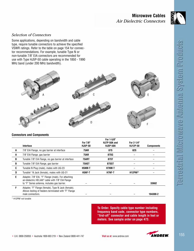
• U.K. 0800-250055 • Australia 1800-803 219 • New Zealand 0800-441-747 Visit us at: www.andrew.com 155
To Order. Specify cable type number including frequency band code, connector type numbers, “first-off” connector and cable length in feet ormeters. See sample order on page 473.
Connectors and ComponentsFor 1-5/8"
For 7/8" HJ7P-50A and For 2-1/4"Interface HJ5P-50 HJSP-50A HJ12P-50 Components
A 7/8" EIA Flange, no gas barrier at interface 75AR 87S 82S –
A 7/8" EIA Flange, gas barrier 75AR 87SG – –
B Tunable 7/8" EIA Flange, no gas barrier at interface 75ART 87ST – –
B Tunable 7/8" EIA Flange, gas barrier 75AGT 87SGT – –
C Tunable N Plug (male), mates with UG-23 H5NM-T H7NM-T – –
D Tunable* N Jack (female), mates with UG-21 H5NF-T H7NF-T H12PNF* –
E Adapter, 7/8" EIA, “F” Flange (male). For attachingair-dielectric HELIAX® cable with 7/8" EIA Flangeto “F” Series antenna, includes gas barrier. – – – 33682
F Adapter, “F” Flange (female), Type N Jack (female).Allows testing of feeders terminated with “F” Flangemale connectors. – – – 104300-2
* H12PNF not tunable
Microwave CablesAir Dielectric Connectors
Selection of ConnectorsSome applications, depending on bandwidth and cabletype, require tunable connectors to achieve the specifiedVSWR ratings. Refer to the table on page 154 for connec-tor recommendations. For example, tunable Type N ornon-tunable 7/8" EIA connectors are recommended foruse with Type HJ5P-50 cable operating in the 1850 - 1990MHz band (under 200 MHz bandwidth).
A C E
B DF
Customer Service Center - Call toll-free from: • U.S.A., Canada and Mexico 1-800-255-1479156
HELIAX elliptical waveguide is the optimum choice formost microwave antenna feeder systems. HELIAX is pre-cision-formed from corrugated high-conductivity copperand has an elliptical cross section. The corrugated wallgives the waveguide excellent crush strength, light weightand good flexibility for ease of handling. A rugged blackpolyethylene jacket provides protection during handlingand installation. A full range of waveguide sizes is available for application from 1.7 to 26.5 GHz.
High PerformanceLow Loss. HELIAX elliptical waveguides are optimized forlowest loss in specific user bands. Attenuation is signifi-cantly lower than that of standard rectangular waveguidesfor these bands. You get highly efficient signal transferwhich optimizes overall system performance.
Low Signal Distortion. The elliptical cross section propa-gates the eTE11 dominate mode, which is similar to theTE10 mode in rectangular waveguide, and operates belowthe cutoff frequencies of higher order modes. Operating inthe frequency band where only the dominant mode canexist eliminates signal distortion due to mode conversionand minimizes VSWR.
Guaranteed VSWR Performance. All factory assembliesare guaranteed to meet stated VSWR specifications. Youget the performance you expect. No surprises, no risk.
Advanced Connector Design. Fixed-tuned premium connector design provides low VSWR performance, eliminating the need for field tuning.
Long Service Life Means Cost-EffectivePerformanceSolid Copper Corrugated Wall gives the waveguide excellent crush strength, light weight and good flexibility.
HELIAX® Elliptical WaveguideGeneral Information
Rugged Black Polyethylene Jacket provides protectionduring handling and installation. The jacket is weather-proof and ultraviolet stabilized to prevent deterioration.Standard jacketing material is suitable for operation downto -54°C (-65°F) and installation down to -40°C (-40°F).
Investment Cast Silicon Brass and Forged Brass connec-tor material, for most sizes, ensures long lasting pressuretightness and corrosion resistance. Connector hardware isstainless steel for corrosion protection and long life.
Advanced Design Accessories are integral HELIAX systemcomponents and are engineered for long term reliability.
Minimum Installation Cost and SimplifiedSystem PlanningHELIAX elliptical waveguide minimizes the cost of detailedwaveguide system planning and has lower installationcost compared with other types of waveguide.
Good Flexibility of the corrugated copper constructionprovides ease of handling during installation. Saves timeand labor.
One-Stop Shopping. A broad range of accessories andcomponents is available from Andrew, all engineered towork together as a system. With Andrew you can avoidthe costly problems of out of sequence deliveries and non-compliant material which can result from dealing withmultiple vendors.
Long Continuous Length availability is a major advantageof HELIAX elliptical waveguide. It can be easily cut tolength for any waveguide run eliminating the need formultiple joints and elbows of flex sections. The result:lower installation cost, easier system planning andincreased reliability. Long lengths also permit convenientstocking at the site.
Connector Attachments are designed so that special toolsor compounds are not required.
Easy to Use Flaring Tools are available for most sizes.Special training is not required.
Additional Services Make the AndrewDifferenceAndrew offers a broad range of services including deliv-ery, installation, and testing of antenna/transmission line systems. We are also prepared to handle all of the otherdetails necessary for complete site construction.
Fast Delivery. Rapid product availability allows Andrew to be a real problem solver for you at installation time. Withschedules to meet, you need to avoid delivery delays, contain costs and get your system operating on time. WithHELIAX elliptical waveguide from Andrew, you can do it.
• U.K. 0800-250055 • Australia 1800-803 219 • New Zealand 0800-441-747 Visit us at: www.andrew.com 157
Gasket O-Ring
Transition Body
Firm Support atRoot of Corrugation
Corrugated Split Flare Ring
Applications Engineering Support. Andrew offers applications engineering support to solve system designproblems and ensure that your waveguide system is properly designed. We can provide expert assistance tomake sure that your waveguide investment will provide acost-effective return.
VSWR CharacteristicsRecommended waveguide and connector assemblies forthe commonly used frequency bands are listed in thetables on pages 160-193. VSWR characteristics shownare guaranteed for factory assemblies within the indicatedbands. They are also typical for assemblies with field-installed connectors. Performance data for other bandsare available on request.
HELIAX® elliptical waveguide is available in standardVSWR, premium (low VSWR) and super premium (lowest VSWR) versions. Selection of waveguide is completed by VSWR testing which is an integral part ofthe manufacturing process. For this reason, standard, premium and super premium versions all carry the EWmarking. Except for attainable VSWR, standard, premiumand super premium waveguides have the same electricaland mechanical characteristics.
All waveguide is tested as part of the manufacturingprocess, and is verified to be at least 0.01 better than thepublished VSWR specifications. This ensures that thepublished specifications will be maintained upon deliveryto the site. See page 201 for details of the high directivityAndrew Hybrid Reflectometer.
Cutting ToleranceWaveguide lengths are measured from connector flangeface to connector flange face. Standard cutting tolerance is+2%, -0%. Closer tolerances are available on special order.
Elliptical Waveguide ConnectorsConnectors are tapered or multi-step transitions fromelliptical to rectangular waveguide cross sections andmate with industry standard rectangular waveguideflanges. Each connector includes a pressure inlet with a1/8" female pipe thread, flange gasket, flange hardwareand assembly instructions. “M” suffix connectors, such as143SEM, have IEC154 compliant flanges, and are suppliedwith metric flange hardware and gasket.
Connector Types AvailableNon-Tunable Connectors are tapered transitions which do not include tuning screws. They are recommended foruse with standard HELIAX elliptical waveguide and havedesignations such as 163DE.
Tunable Connectors are tapered transitions which includetuning screws to minimize assembly VSWR. Tunable connectors are identified by a “T” suffix. For example,163DET is a tunable version of the 163DE non-tunableconnector mentioned above.
When ordered as part of a premium or super premium factory assembly, the connectors are factory attached andtuned. Tunable connectors are suitable for field attach-ment when the capability for field tuning exists. Tunableconnectors are recommended for use with premium andsuper premium HELIAX elliptical waveguide.
Fixed-Tuned Connectors have a multi-step mating sectionwhich is precisely machined to provide low VSWR over abroad bandwidth without the use of tuning screws. Fixed-tuned connectors are recommended for use with standardand premium HELIAX elliptical waveguide. The connectorshave designations which include an “S” after the seriesnumber. Types are: 143SEM, 163SEM*, 164SEM*,290SC**, 1220ASC* and 2180SEM.* Patented United States 4,540,959; Australia 565,511; Canada 1,221,751.** Patented United States 4,642,585; Australia 578,507; Canada 1,224,897.
Cutaway View of Fixed-TunedConnector
HELIAX® Elliptical WaveguideGeneral Information
Revised 9/00
Customer Service Center - Call toll-free from: • U.S.A., Canada and Mexico 1-800-255-1479158
* HELIAX is the registered trademark under which flexible elliptical waveguides are sold by Andrew.
** Patented United States 4,590,785
Connector MaterialsAll connectors except for the 117, 120 and 128 series, areconstructed of brass. 117, 120 and 128 series are siliconeimpregnated, nickel plated aluminum. Both materials arelong lasting, pressure tight and compatible with the wave-guide material to prevent corrosion. A precision moldedsilicone rubber gasket conforms to the shape of the waveguide corrugations and provides a reusable pressureseal without the need for sealing compounds. All hardwareis stainless steel for corrosion protection and long life.
Connectors Are Easy to AttachAll connectors, except those for EW17, 20, 28 and 85,incorporate a corrugated split flare ring to accurately position the elliptical waveguide relative to the transition.When used with the new compact flaring tool kit, thisallows consistent VSWR to be achieved for connectorswhich do not require field tuning.
Saw Guide. Split flare ring connectors include a dispos-able plastic saw guide to assure a square cut of the wave-guide and the proper length for flaring.
Integral Flare Aid. The corrugated split flare ring functions as a flare aid. This innovation results in:
• Improved electrical performance through optimumpositioning of the corrugation runout relative to theelectrical axis of the waveguide.
• Firm support throughout the corrugation allowing high mating pressure at the point of electrical contact to eliminate intermodulation distortion.
• Fast, accurate field connector attachment.
• Field attachment with standard hand tools.
Compact Flaring ToolNew compact flaring tool** kits are now available exclu-sively from Andrew with many advantages over other flaring tools. See page 198.
HELIAX* Elliptical Waveguide AssembliesAssemblies consist of waveguide cut to length and terminated with connectors on each end. Connectors aretransitions from the elliptical to rectangular cross sectionand are described in detail above.
Assemblies are available in standard and premium versions. Super premium (lowest VSWR) versions areavailable for certain sizes.
Standard Assemblies consist of standard waveguide andnon-tunable, fixed tuned or pre-tuned connectors.
HELIAX® Elliptical WaveguideGeneral Information
Premium Assemblies consist of premium waveguide andtunable connectors or fixed-tuned premium connectors.Premium waveguide has excellent VSWR characteristicsfor very low group delay distortion and noise.
Super Premium Assemblies consist of super premiumwaveguide and tunable connectors. Super premiumassemblies offer the lowest available VSWR for minimumgroup delay distortion and noise.
Factory or Field AssembliesAll of the above assembly types can be configured as factory or field assemblies. VSWR specifications given in this catalog are guaranteed for factory assemblies andare typical for field fitted assemblies.
For long bulk lengths of premium elliptical waveguide it isnot possible to verify the return loss performance alongthe entire length. Therefore, when possible, premiumwaveguide should be ordered in the lengths in which itwill be used.
Field-Fitted Assemblies. Bulk lengths may be orderedand individual feeders cut to length and connectorsinstalled on site for minimum waste. Connectors can beattached without need of special tools or compounds.Compact flaring tools are available to ensure consistentVSWR performance. Fixed-tuned premium connectors are recommended for field-fitted applications requiringlow VSWR without field tuning.
Factory Assemblies. When specific lengths are known,waveguide can be cut to the desired length and connec-tors factory attached and, where applicable, tuned.
Optional Fire-Retardant JacketSelected sizes of HELIAX elliptical waveguide are available with a fire-retardant, non-halogenated jacket toavoid the need for costly conduit.
For use in the United States, these fire-retardant jacketedelliptical waveguides are UL listed as Type CATVR andmarked accordingly on the gray jacket. The Type CATVRrating permits installation in building risers.
This jacketing material is intended for installation indoorsor in other confined areas where there is limited exposureto sunlight or ultra-violet radiation.
The CATVP elliptical waveguide is available in selectedsizes. Products with this rating are found in ducts,plenums or other spaces used for environmental air.Types of unjacketed CATVP waveguide pass the moststringent fire resistance tests and are tagged as “UL®Type CATVP.”
Typical SystemsExample microwave antenna systems using HELIAX elliptical waveguide are described on pages 26-34. Typicalcomponents and mounting accessories are illustrated.
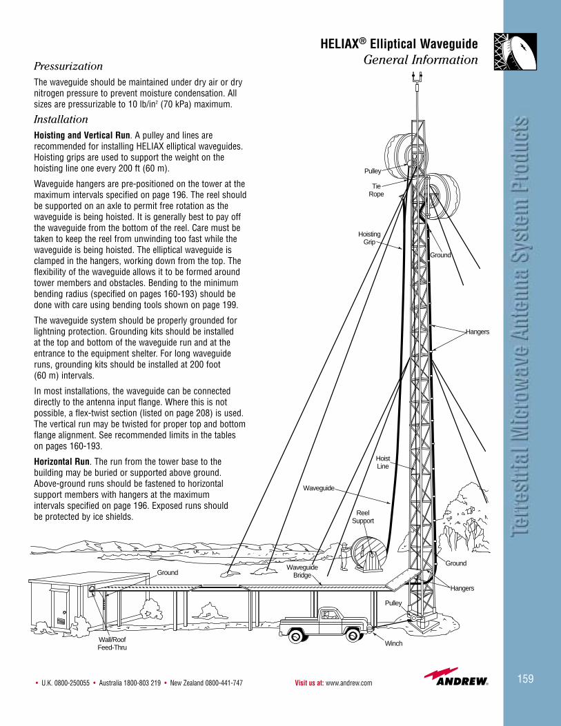
• U.K. 0800-250055 • Australia 1800-803 219 • New Zealand 0800-441-747 Visit us at: www.andrew.com 159
Pulley
TieRope
HoistingGrip
Ground
Hangers
HoistLine
Waveguide
Reel Support
Hangers
Pulley
Winch
WaveguideBridge
GroundGround
Wall/RoofFeed-Thru
PressurizationThe waveguide should be maintained under dry air or drynitrogen pressure to prevent moisture condensation. Allsizes are pressurizable to 10 lb/in2 (70 kPa) maximum.
InstallationHoisting and Vertical Run. A pulley and lines are recommended for installing HELIAX elliptical waveguides.Hoisting grips are used to support the weight on thehoisting line one every 200 ft (60 m).
Waveguide hangers are pre-positioned on the tower at themaximum intervals specified on page 196. The reel shouldbe supported on an axle to permit free rotation as thewaveguide is being hoisted. It is generally best to pay offthe waveguide from the bottom of the reel. Care must betaken to keep the reel from unwinding too fast while thewaveguide is being hoisted. The elliptical waveguide isclamped in the hangers, working down from the top. Theflexibility of the waveguide allows it to be formed aroundtower members and obstacles. Bending to the minimumbending radius (specified on pages 160-193) should bedone with care using bending tools shown on page 199.
The waveguide system should be properly grounded forlightning protection. Grounding kits should be installed at the top and bottom of the waveguide run and at theentrance to the equipment shelter. For long waveguideruns, grounding kits should be installed at 200 foot(60 m) intervals.
In most installations, the waveguide can be connecteddirectly to the antenna input flange. Where this is not possible, a flex-twist section (listed on page 208) is used.The vertical run may be twisted for proper top and bottomflange alignment. See recommended limits in the tableson pages 160-193.
Horizontal Run. The run from the tower base to the building may be buried or supported above ground.Above-ground runs should be fastened to horizontal support members with hangers at the maximum intervals specified on page 196. Exposed runs should be protected by ice shields.
HELIAX® Elliptical WaveguideGeneral Information
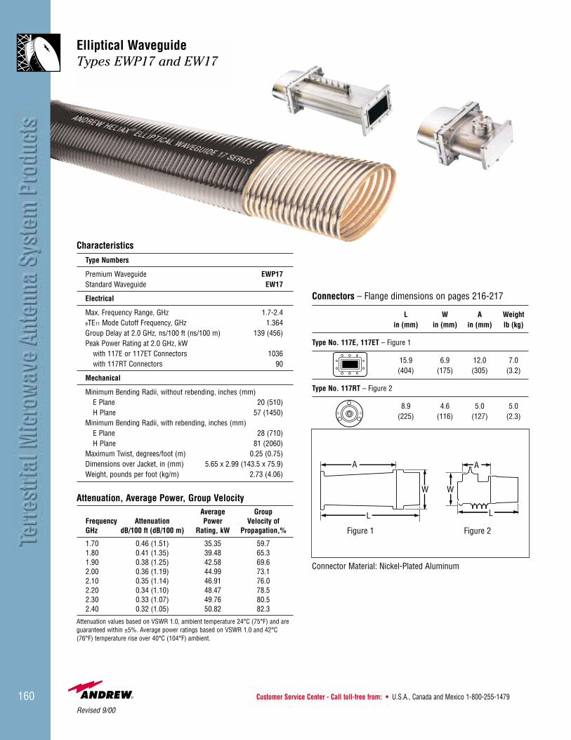
Customer Service Center - Call toll-free from: • U.S.A., Canada and Mexico 1-800-255-1479160
Connectors – Flange dimensions on pages 216-217
L W A Weightin (mm) in (mm) in (mm) lb (kg)
Type No. 117E, 117ET – Figure 1
15.9 6.9 12.0 7.0(404) (175) (305) (3.2)
Type No. 117RT – Figure 2
8.9 4.6 5.0 5.0(225) (116) (127) (2.3)
CharacteristicsType Numbers
Premium Waveguide EWP17Standard Waveguide EW17
Electrical
Max. Frequency Range, GHz 1.7-2.4eTE11 Mode Cutoff Frequency, GHz 1.364Group Delay at 2.0 GHz, ns/100 ft (ns/100 m) 139 (456)Peak Power Rating at 2.0 GHz, kW
with 117E or 117ET Connectors 1036with 117RT Connectors 90
Mechanical
Minimum Bending Radii, without rebending, inches (mm)E Plane 20 (510)H Plane 57 (1450)
Minimum Bending Radii, with rebending, inches (mm)E Plane 28 (710)H Plane 81 (2060)
Maximum Twist, degrees/foot (m) 0.25 (0.75)Dimensions over Jacket, in (mm) 5.65 x 2.99 (143.5 x 75.9)Weight, pounds per foot (kg/m) 2.73 (4.06)
Attenuation, Average Power, Group VelocityAverage Group
Frequency Attenuation Power Velocity ofGHz dB/100 ft (dB/100 m) Rating, kW Propagation,%
1.70 0.46 (1.51) 35.35 59.71.80 0.41 (1.35) 39.48 65.31.90 0.38 (1.25) 42.58 69.62.00 0.36 (1.19) 44.99 73.12.10 0.35 (1.14) 46.91 76.02.20 0.34 (1.10) 48.47 78.52.30 0.33 (1.07) 49.76 80.52.40 0.32 (1.05) 50.82 82.3
Attenuation values based on VSWR 1.0, ambient temperature 24°C (75°F) and areguaranteed within ±5%. Average power ratings based on VSWR 1.0 and 42°C(76°F) temperature rise over 40°C (104°F) ambient.
Figure 1 Figure 2
Elliptical WaveguideTypes EWP17 and EW17
L
Connector Material: Nickel-Plated Aluminum
A A
L
W W
Revised 9/00
How
To
Orde
r:
• U.K. 0800-250055 • Australia 1800-803 219 • New Zealand 0800-441-747 Visit us at: www.andrew.com 161
Ordering Information for Waveguide AssembliesFrequency Waveguide Flange Connector VSWR, max.** (R.L. dB)
GHz* Type Type†† Tunable Up to 300 ft (90 m)
Premium Waveguide Assemblies
1.7-2.1 EWP17-17 CPR430G 117ET 1.19 (21.2)7/8" EIA (gas block) 117RT 1.23 (19.7)7/8" EIA (gas pass) 117RT-3 1.23 (19.7)
1.9-2.3 EWP17-19 CPR430G 117ET 1.17 (22.1)7/8" EIA (gas block) 117RT 1.27 (18.5)7/8" EIA (gas pass) 117RT-3 1.27 (18.5)
Standard Waveguide Assemblies Non-Tunable
1.7-2.3 EW17 CPR430G 117E 1.25 (19.1)
* Contact Andrew for information on other frequency bands.** VSWR, max. (R.L.,dB) Up to 300 ft (90 m). The indicated maximum characteristics are guaranteed for factory assemblies and are typical for field assemblies.†† For detailed information on mating flanges, refer to pages 214-218.
Description Type No.
Hangers and Adapters
Hanger Kit of 10, Recommended maximum spacingfor outdoor installation is 6 ft (1.83 m)* 31766A-9Hardware Kit of 10, 3/8" bolts, lock washers, nuts
3/4" (19 mm) long 31769-51" (25 mm) long 31769-1
Angle Adapter Kit of 10. Stainless steel 31768ARound Member Adapter Kit of 10. Two kits are requiredwith each EW17 hanger kit. Stainless steel Member Diameter, in (mm)
1-2 (25-50) 31670-12-3 (50-75) 31670-23-4 (75-100) 31670-34-5 (100-125) 31670-45-6 (125-150) 31670-5
45° Adapter Kit of 10. Galvanized steel 42334Threaded Rod Support, 3/8” rod, nuts, washers, ceiling bracket
12 in (305 mm) long, kit of 1 3177112 in (305 mm) long, kit of 5 31771-424 in (610 mm) long, kit of 1 31771-924 in (610 mm) long, kit of 5 31771-6
Tower Standoff Kit of 10. 1 in (25 mm) standoffMember Diameter, in (mm)
0.75-1.5 (20-40) 30848-51.5-3.0 (40-75) 30848-43-4 (75-100) 30848-14-5 (100-125) 30848-25-6 (125-150) 30848-3
Tower Standoff Kit of 10. 2.5 in (60 mm) standoffMember Diameter, in (mm)
3-4 (75-100) 41108A-14-5 (100-125) 41108A-25-6 (125-150) 41108A-3
* Standard conditions: 125 mph (200 km/h) survival wind velocity, 0.5 in (13 mm) radial ice. For other conditions see page 196
Accessories – Photos and detailed descriptions on pages 194-200
Description Type No.
Other Accessories
Splice 117ZGrounding Kit with factory attached lug 204989-6Grounding Kit with field attachable crimp-on lug 204989-26Grounding Kit with field attachable screw-on lug 204989-36Crimping Tool to field attach lug to Grounding Kit 207270Wall/Roof Feed-Thru 35849A-10Holsting Grip 34759Bending Tool Kit. One each E and H Plane tool EWBTK-5Connector Reattachment Kit 33544-10
A sample order is shown on page 473.
Specify complete waveguide Type Number, including frequency band code, where listed, and length in feet ormeters. See “Waveguide Assemblies” table.
Specify connector Type Numbers and “attached” or“unattached”. See “Waveguide Assemblies” table. When attached connectors on an assembly are different,specify which is “first off” the reel.
Further Information:
For general information on HELIAX® elliptical waveguide,see pages 156-159.
Revised 3/01 & 5/01

Customer Service Center - Call toll-free from: • U.S.A., Canada and Mexico 1-800-255-1479162
Connectors – Flange dimensions on pages 216-217
L W A Weightin (mm) in (mm) in (mm) lb (kg)
Type No. 120E – Figure 1
5.8 6.2 1.8 3.5(147) (157) (46) (1.6)
Type No. E20MB-014, E20MP-014 – Figure 2
9.0 4.4 4.4 4.8(229) (111) (111) (2.2)
CharacteristicsType Numbers
Standard Waveguide EW20
Electrical
Max. Frequency Range, GHz* 1.9-2.7
eTE11 Mode Cutoff Frequency, GHz 1.57Group Delay at 2.6 GHz, ns/100 ft (ns/100m) 127 (418)Peak Power Rating at 2.6 GHz, kW
with 120E Connectors 663with E20MB-014 and E20MP-014 Connectors 90
Mechanical
Minimum Bending Radii, without rebending, in (mm)E Plane 18 (460)H Plane 50 (1270)
Minimum Bending Radii, with rebending, in (mm)E Plane 26 (660)H Plane 71 (1800)
Maximum Twist, degrees/foot (m) 0.25 (0.75)Dimension over Jacket, in (mm) 5.02 x 2.83 (127.5 x 71.9)Weight, pounds per foot (kg/m) 1.85 (2.76)
* Actual usable range is limited by the connecting rectangular waveguide
Attenuation, Average Power, Group VelocityAverage Group
Frequency Attenuation Power Velocity ofGHz dB/100 ft (dB/100 m) Rating, kW Propagation,%
1.9 0.61 (2.01) 24.06 56.32.0 0.55 (1.81) 26.65 61.92.1 0.51 (1.69) 28.64 66.42.2 0.49 (1.60) 30.22 70.02.3 0.47 (1.53) 31.50 73.02.4 0.45 (1.48) 32.56 75.62.5 0.44 (1.45) 33.44 77.82.6 0.43 (1.41) 34.19 79.72.7 0.42 (1.39) 34.82 81.4
Attenuation values based on VSWR 1.0, ambient temperature 24°C (75°F) and are guaranteed within ±5%. Average power ratings based on VSWR 1.0 and 42°C (76°F) temperature rise over 40°C (104°F) ambient.
Figure 2
L
Connector Material: Nickel-Plated Aluminum
A A
W W
Figure 1
L
Elliptical WaveguideType EW20
Revised 9/00
• U.K. 0800-250055 • Australia 1800-803 219 • New Zealand 0800-441-747 Visit us at: www.andrew.com 163
Description Type No.
Hangers and Adapters
Hanger Kit of 10, Recommended maximum spacingfor outdoor installation is 5.5 ft (1.68 m)* 31766A-10Hardware Kit of 10, 3/8" bolts, lock washers, nuts
3/4" (19 mm) long 31769-51" (25 mm) long 31769-1
Angle Adapter Kit of 10. Stainless steel 31768ARound Member Adapter Kit of 10. Two kits are requiredwith each EW20 hanger kit. Stainless steelMember Diameter, in (mm)
1-2 (25-50) 31670-12-3 (50-75) 31670-23-4 (75-100) 31670-34-5 (100-125) 31670-45-6 (125-150) 31670-5
45° Adapter Kit of 10. Galvanized steel 42334Threaded Rod Support, 3/8” rod, nuts, washers, ceiling bracket
12 in (305 mm) long, kit of 1 3177112 in (305 mm) long, kit of 5 31771-424 in (610 mm) long, kit of 1 31771-924 in (610 mm) long, kit of 5 31771-6
Tower Standoff Kit of 10. 1 in (25 mm) standoffMember Diameter, in (mm)
0.75-1.5 (20-40) 30848-51.5-3.0 (40-75) 30848-43-4 (75-100) 30848-14-5 (100-125) 30848-25-6 (125-150) 30848-3
Tower Standoff Kit of 10. 2.5 in (60 mm) standoffMember Diameter, in (mm)
3-4 (75-100) 41108A-14-5 (100-125) 41108A-25-6 (125-150) 41108A-3
* Standard conditions: 125 mph (200 km/h) survival wind velocity, 0.5 in (13 mm) radial ice. For other conditions see page 196.
Accessories – Photos and detailed descriptions on pages 194-200
Description Type No.
Other Accessories
Splice 120ZGrounding Kit with factory attached lug 204989-6Grounding Kit with field attachable crimp-on lug 204989-26Grounding Kit with field attachable screw-on lug 204989-36Crimping Tool to field attach lug to Grounding Kit 207270Wall/Roof Feed-Thru 35849A-10Holsting Grip 34759Bending Tool Kit. One each E and H Plane tool EWBTK-5Connector Reattachment Kit 33544-11
Ordering Information for Waveguide AssembliesFrequency Waveguide Flange Connector Pressure VSWR, max.** (R.L. dB)GHz* Type Type†† Tunable Window Up to 300 ft (90 m)
2.5-2.7 EW20-25 mates with CPR340G 120E 55001-340 1.15 (23.0)2.5-2.7 EW20-25 7/8" EIA (with gas barrier) E20MB-014 *** 1.15 (23.0)
7/8" EIA (without gas barrier) E20MP-014 – 1.15 (23.0)2.1-2.7 EW20-21W 7/8" EIA (with gas barrier) E20MB-014 *** 1.15 (23.0)
7/8" EIA (without gas barrier) E20MP-014 – 1.15 (23.0)
* Contact Andrew for information on other frequency bands.** VSWR, max. (R.L.,dB) Up to 300 ft (90 m). The indicated maximum characteristics are guaranteed for factory assemblies and are typical for field assemblies.***Not applicable †† For detailed information on mating flanges, refer to pages 214-218.
How
To
Orde
r:
A sample order is shown on page 473.
Specify complete waveguide Type Number, including frequency band code, where listed, and length in feet ormeters. See “Waveguide Assemblies” table.
Specify connector Type Numbers and “attached” or“unattached”. See “Waveguide Assemblies” table. When attached connectors on an assembly are different,specify which is “first off” the reel.
Further Information:
For general information on HELIAX® elliptical waveguide,see pages 156-159.
Revised 5/01
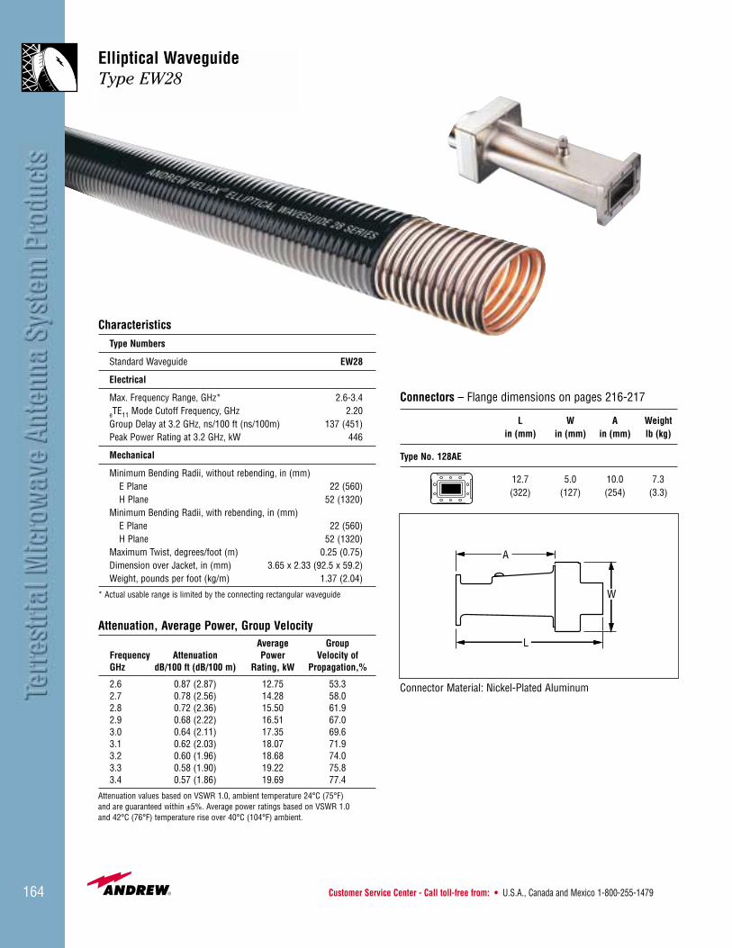
Customer Service Center - Call toll-free from: • U.S.A., Canada and Mexico 1-800-255-1479164
Connectors – Flange dimensions on pages 216-217
L W A Weightin (mm) in (mm) in (mm) lb (kg)
Type No. 128AE
12.7 5.0 10.0 7.3(322) (127) (254) (3.3)
CharacteristicsType Numbers
Standard Waveguide EW28
Electrical
Max. Frequency Range, GHz* 2.6-3.4
eTE11 Mode Cutoff Frequency, GHz 2.20Group Delay at 3.2 GHz, ns/100 ft (ns/100m) 137 (451)Peak Power Rating at 3.2 GHz, kW 446
Mechanical
Minimum Bending Radii, without rebending, in (mm)E Plane 22 (560)H Plane 52 (1320)
Minimum Bending Radii, with rebending, in (mm)E Plane 22 (560)H Plane 52 (1320)
Maximum Twist, degrees/foot (m) 0.25 (0.75)Dimension over Jacket, in (mm) 3.65 x 2.33 (92.5 x 59.2)Weight, pounds per foot (kg/m) 1.37 (2.04)
* Actual usable range is limited by the connecting rectangular waveguide
Attenuation, Average Power, Group VelocityAverage Group
Frequency Attenuation Power Velocity ofGHz dB/100 ft (dB/100 m) Rating, kW Propagation,%
2.6 0.87 (2.87) 12.75 53.32.7 0.78 (2.56) 14.28 58.02.8 0.72 (2.36) 15.50 61.92.9 0.68 (2.22) 16.51 67.03.0 0.64 (2.11) 17.35 69.63.1 0.62 (2.03) 18.07 71.93.2 0.60 (1.96) 18.68 74.03.3 0.58 (1.90) 19.22 75.83.4 0.57 (1.86) 19.69 77.4
Attenuation values based on VSWR 1.0, ambient temperature 24°C (75°F) and are guaranteed within ±5%. Average power ratings based on VSWR 1.0 and 42°C (76°F) temperature rise over 40°C (104°F) ambient.
A
L
Connector Material: Nickel-Plated Aluminum
W
Elliptical WaveguideType EW28
• U.K. 0800-250055 • Australia 1800-803 219 • New Zealand 0800-441-747 Visit us at: www.andrew.com 165
Description Type No.
Hangers and Adapters
Hanger Kit of 10, Recommended maximum spacingfor outdoor installation is 5 ft (1.52 m)* 31766A-11Hardware Kit of 10, 3/8" bolts, lock washers, nuts
3/4" (19 mm) long 31769-51" (25 mm) long 31769-1
Angle Adapter Kit of 10. Stainless steel 31768ARound Member Adapter Kit of 10. Stainless steelMember Diameter, in (mm)
1-2 (25-50) 31670-12-3 (50-75) 31670-23-4 (75-100) 31670-34-5 (100-125) 31670-45-6 (125-150) 31670-5
45° Adapter Kit of 10. Galvanized steel 42334Threaded Rod Support, 3/8” rod, nuts, washers, ceiling bracket
12 in (305 mm) long, kit of 1 3177112 in (305 mm) long, kit of 5 31771-424 in (610 mm) long, kit of 1 31771-924 in (610 mm) long, kit of 5 31771-6
Tower Standoff Kit of 10. 1 in (25 mm) standoffMember Diameter, in (mm)
0.75-1.5 (20-40) 30848-51.5-3.0 (40-75) 30848-43-4 (75-100) 30848-14-5 (100-125) 30848-25-6 (125-150) 30848-3
Tower Standoff Kit of 10. 2.5 in (60 mm) standoffMember Diameter, in (mm)
3-4 (75-100) 41108A-14-5 (100-125) 41108A-25-6 (125-150) 41108A-3
* Standard conditions: 125 mph (200 km/h) survival wind velocity, 0.5 in (13 mm) radial ice. For other conditions see page 196
Accessories – Photos and detailed descriptions on pages 194-200.
Description Type No.
Other Accessories
Splice 128AZGrounding Kit with factory attached, one-hole lug 204989-5Grounding Kit with factory attached, two-hole lug 241088-5Grounding Kit with field attachable crimp-on, one-hole lug 204989-25Grounding Kit with field attachable crimp-on, two-hole lug 241088-10Grounding Kit with field attachable screw-on lug 204989-35Crimping Tool to field attach lug to Grounding Kit 207270Wall-Roof Feed Thru 35849-13Hoisting Grip 26985ABending Tool Kit. One each E and H Plane tool EWBTK-4
Ordering Information for Waveguide AssembliesFrequency Waveguide Flange Connector Pressure VSWR, max.** (R.L. dB)GHz* Type Type†† Tunable Window Up to 300 ft (90 m)
2.9-3.1 EW28 CPR284G 128AE 55001-284 1.20 (20.8)3.1-3.4 EW28 CPR284G 128AE 55001-284 1.15 (23.0)
* Contact Andrew for information on other frequency bands.** VSWR, max. (R.L.,dB) Up to 300 ft (90 m). The indicated maximum characteristics are guaranteed for factory assemblies and are typical for field assemblies.†† For detailed information on mating flanges, refer to pages 214-218.
How
To
Orde
r:
A sample order is shown on page 473.
Specify complete waveguide Type Number, including frequency band code, where listed, and length in feet ormeters. See “Waveguide Assemblies” table.
Specify connector Type Numbers and “attached” or“unattached”. See “Waveguide Assemblies” table. When attached connectors on an assembly are different,specify which is “first off” the reel.
Further Information:
For general information on HELIAX® elliptical waveguide,see pages 156-159.
Revised 7/00 & 5/01
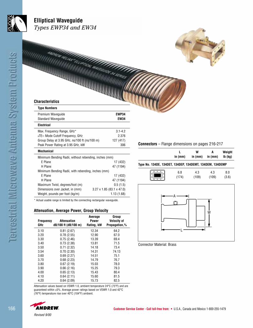
Customer Service Center - Call toll-free from: • U.S.A., Canada and Mexico 1-800-255-1479166
A
W
L
Connector Material: Brass
Connectors – Flange dimensions on pages 216-217
L W A Weightin (mm) in (mm) in (mm) lb (kg)
Type No. 134DE, 134DET, 134DEP, 134DEMT, 134DEM, 134DEMP
6.8 4.3 4.3 8.0(174) (109) (109) (3.6)
CharacteristicsType Numbers
Premium Waveguide EWP34Standard Waveguide EW34
Electrical
Max. Frequency Range, GHz* 3.1-4.2eTE11 Mode Cutoff Frequency, GHz 2.376Group Delay at 3.95 GHz, ns/100 ft (ns/100 m) 127 (417)Peak Power Rating at 3.95 GHz, kW 306
Mechanical
Minimum Bending Radii, without rebending, inches (mm)E Plane 17 (432)H Plane 47 (1194)
Minimum Bending Radii, with rebending, inches (mm)E Plane 17 (432)H Plane 47 (1194)
Maximum Twist, degrees/foot (m) 0.5 (1.5)Dimensions over Jacket, in (mm) 3.27 x 1.85 (83.1 x 47.0)Weight, pounds per foot (kg/m) 1.13 (1.68)
* Actual usable range is limited by the connecting rectangular waveguide.
Attenuation, Average Power, Group VelocityAverage Group
Frequency Attenuation Power Velocity ofGHz dB/100 ft (dB/100 m) Rating, kW Propagation,%
3.10 0.81 (2.67) 12.34 64.23.20 0.78 (2.55) 12.90 67.03.30 0.75 (2.46) 13.39 69.43.40 0.73 (2.38) 13.81 71.53.50 0.71 (2.32) 14.18 73.43.54 0.70 (2.30) 14.31 74.133.60 0.69 (2.27) 14.51 75.13.70 0.68 (2.23) 14.79 76.73.80 0.67 (2.19) 15.03 78.03.90 0.66 (2.16) 15.25 79.34.00 0.65 (2.13) 15.43 80.44.10 0.64 (2.11) 15.60 81.54.20 0.64 (2.09) 15.73 82.5
Attenuation values based on VSWR 1.0, ambient temperature 24°C (75°F) and areguaranteed within ±5%. Average power ratings based on VSWR 1.0 and 42°C(76°F) temperature rise over 40°C (104°F) ambient.
Elliptical WaveguideTypes EWP34 and EW34
Revised 9/00
• U.K. 0800-250055 • Australia 1800-803 219 • New Zealand 0800-441-747 Visit us at: www.andrew.com 167
Ordering Information for Waveguide AssembliesVSWR, max.**
Frequency Waveguide Flange Connector† Flex-Twist (R.L. dB)GHz* Type Type†† Tunable Pre-Tuned Pressure Window 2 ft (0.6 m) Up to 300 ft (90 m)
Premium Waveguide Assemblies
3.4-3.9 EWP34-34 CPR229G 134DET – 55001-229 F229PC0240CS 1.10 (26.4)3.54-4.2 EWP34-35 CPR229G 134DET 134DEP-2 55001-229 F229PC0240CA 1.08 (28.3)
PDR40 134DEMT 134DEMP-2 223306-40 F229MH0600HA 1.08 (28.3)3.7-4.2 EWP34-37 CPR229G 134DET 134DEP-1 55001-229 F229PC0240CA 1.08 (28.3)
Standard Waveguide Assemblies Non-Tunable
3.1-3.6 EW34-31 CPR229G 134DE – 55001-229 F229PC0240CS 1.15 (23.1)3.4-4.2 EW34 CPR229G 134DE – 55001-229 F229PC0240CS 1.15 (23.1)
* Contact Andrew for information on other frequency bands.** VSWR, max. (R.L.,dB) Up to 300 ft (90 m). The indicated maximum characteristics are guaranteed for factory assemblies and are typical for field assemblies.† “Pre-tuned” connectors are for field attachment only. “Tunable” connectors ordered with factory assemblies are factory tuned.†† For detailed information on mating flanges, refer to pages 214-218.
Description Type No.
Hangers and Adapters
Hanger Kit of 10, Recommended maximum spacingfor outdoor installation is 4.5 ft (1.37 m)* 42396A-15Hardware Kit of 10, 3/8" bolts, lock washers, nuts
3/4" (19 mm) long 31769-51" (25 mm) long 31769-1
Angle Adapter Kit of 10. Stainless steel 31768ARound Member Adapter Kit of 10. Stainless steelMember Diameter, in (mm)
1-2 (25-50) 31670-12-3 (50-75) 31670-23-4 (75-100) 31670-34-5 (100-125) 31670-45-6 (125-150) 31670-5
45° Adapter Kit of 10. Galvanized steel 42334Threaded Rod Support, 3/8” rod, nuts, washers, ceiling bracket
12 in (305 mm) long, kit of 1 3177112 in (305 mm) long, kit of 5 31771-424 in (610 mm) long, kit of 1 31771-924 in (610 mm) long, kit of 5 31771-6
Tower Standoff Kit of 10. 1 in (25 mm) standoffMember Diameter, in (mm)
0.75-1.5 (20-40) 30848-51.5-3.0 (40-75) 30848-43-4 (75-100) 30848-14-5 (100-125) 30848-25-6 (125-150) 30848-3
Tower Standoff Kit of 10. 2.5 in (60 mm) standoffMember Diameter, in (mm)
3-4 (75-100) 41108A-14-5 (100-125) 41108A-25-6 (125-150) 41108A-3
* Standard conditions: 125 mph (200 km/h) survival wind velocity, 0.5 in (13 mm) radial ice. For other conditions see page 196.
Accessories – Photos and detailed descriptions on pages 194-200
Description Type No.
Other Accessories
Splice 134DZGrounding Kit with factory attached, one-hole lug 204989-5Grounding Kit with factory attached, two-hole lug 241088-5Grounding Kit with field attachable crimp-on, one-hole lug 204989-25Grounding Kit with field attachable crimp-on, two-hole lug 241088-10Grounding Kit with field attachable screw-on lug 204989-35Crimping Tool to field attach lug to Grounding Kit 207270Hoisting Grip 26985ABending Tool Kit. One each E and H Plane tool EWBTK-4Connector Reattachment Kit 33544-43Wall-Roof Feed Thru 35849A-17Waveguide Boot for Plates (below),
4 in (102 mm) dia. 204679-345 in (127 mm) dia 48939-34
Feed-Thru Plate for Boots (above)
Openings For 4 in Boots For 5 in Boots
1 204673-1 48940-11 204673-2 –2 – 48940-23 – 48940-34 204673-4 48940-46 – 48940-68 204673-8 –
Revised 5/01
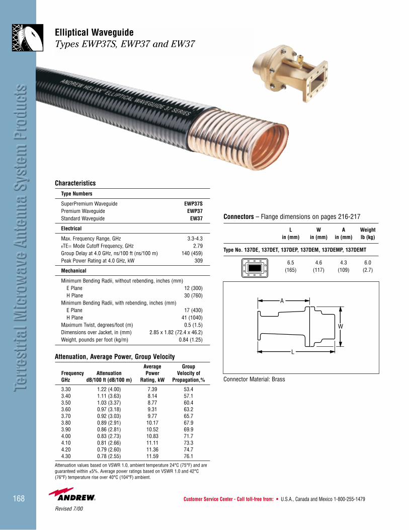
Customer Service Center - Call toll-free from: • U.S.A., Canada and Mexico 1-800-255-1479168
W
Elliptical WaveguideTypes EWP37S, EWP37 and EW37
CharacteristicsType Numbers
SuperPremium Waveguide EWP37SPremium Waveguide EWP37Standard Waveguide EW37
Electrical
Max. Frequency Range, GHz 3.3-4.3eTE11 Mode Cutoff Frequency, GHz 2.79Group Delay at 4.0 GHz, ns/100 ft (ns/100 m) 140 (459)Peak Power Rating at 4.0 GHz, kW 309
Mechanical
Minimum Bending Radii, without rebending, inches (mm)E Plane 12 (300)H Plane 30 (760)
Minimum Bending Radii, with rebending, inches (mm)E Plane 17 (430)H Plane 41 (1040)
Maximum Twist, degrees/foot (m) 0.5 (1.5)Dimensions over Jacket, in (mm) 2.85 x 1.82 (72.4 x 46.2)Weight, pounds per foot (kg/m) 0.84 (1.25)
Attenuation, Average Power, Group VelocityAverage Group
Frequency Attenuation Power Velocity ofGHz dB/100 ft (dB/100 m) Rating, kW Propagation,%
3.30 1.22 (4.00) 7.39 53.43.40 1.11 (3.63) 8.14 57.13.50 1.03 (3.37) 8.77 60.43.60 0.97 (3.18) 9.31 63.23.70 0.92 (3.03) 9.77 65.73.80 0.89 (2.91) 10.17 67.93.90 0.86 (2.81) 10.52 69.94.00 0.83 (2.73) 10.83 71.74.10 0.81 (2.66) 11.11 73.34.20 0.79 (2.60) 11.36 74.74.30 0.78 (2.55) 11.59 76.1
Attenuation values based on VSWR 1.0, ambient temperature 24°C (75°F) and areguaranteed within ±5%. Average power ratings based on VSWR 1.0 and 42°C(76°F) temperature rise over 40°C (104°F) ambient.
A
L
Connector Material: Brass
Connectors – Flange dimensions on pages 216-217
L W A Weightin (mm) in (mm) in (mm) lb (kg)
Type No. 137DE, 137DET, 137DEP, 137DEM, 137DEMP, 137DEMT
6.5 4.6 4.3 6.0(165) (117) (109) (2.7)
Revised 7/00
• U.K. 0800-250055 • Australia 1800-803 219 • New Zealand 0800-441-747 Visit us at: www.andrew.com 169
Ordering Information for Waveguide AssembliesFrequency Waveguide Flange Connector† Flex-Twist
GHz* Type Type†† Tunable Pre-Tuned Pressure Window 2 ft (0.6 m)
Super Premium Waveguide Assemblies VSWR 1.06 (30.7)**
3.7–4.2 EWP37S CPR229G 137DET – 55001-229 F229PC0240CAPDR40 137DEMT – 223306-40 F229PH0600HA
Premium Waveguide Assemblies VSWR 1.08 (28.3)**
3.4-3.9 EWP37-34W*** CPR229G 137DET – 55001-229 F229PC0240CS3.4-3.9 EWP37-34*** PDR40 – 137DEMP-3 223306-40 F229MH0600HS3.54-4.2 EWP37-35 CPR229G 137DET 137DEP-2 55001-229 F229PC0240CA
PDR40 – 137DEMP-2 223306-40 F229MH0600HA3.52-4.2 EWP37-35W CPR229G 137DET 137DEP-2 55001-229 F229PC0240CA
PDR40 – 137DEMP-2 223306-40 F229MH0600HA3.6-4.2 EWP37-36 CPR229G 137DET – 55001-229 F229PC0240CA3.7-4.2 EWP37-37 CPR229G 137DET 137DEP-1 55001-229 F229PC0240CA
Standard Waveguide Assemblies Non-Tunable VSWR 1.15 (23.1)**
3.4–4.2 EW37 CPR229G 137DE – 55001-229 F229PC0240CSPDR40 137DEM – 223306-40 F229MH0600HS
* Contact Andrew for information on other frequency bands.** VSWR max., (R.L., dB). The indicated maximum VSWR characteristics are guaranteed for factory assemblies and are typical for field assemblies.*** VSWR 1.10 (26.4) † “Pre-tuned” connectors are for field attachment only. “Tunable” connectors ordered with factory assemblies are factory tuned. †† For detailed information on mating flanges, refer to pages 214-218.
Description Type No.
Hangers and Adapters
Hanger Kit of 10, Recommended maximum spacingfor outdoor installation is 4.5 ft (1.37 m)* 42396A-4Hardware Kit of 10, 3/8" bolts, lock washers, nuts
3/4" (19 mm) long 31769-51" (25 mm) long 31769-1
Angle Adapter Kit of 10. Stainless steel 31768ARound Member Adapter Kit of 10. Stainless steelMember Diameter, in (mm)
1-2 (25-50) 31670-12-3 (50-75) 31670-23-4 (75-100) 31670-34-5 (100-125) 31670-45-6 (125-150) 31670-5
45° Adapter Kit of 10. Galvanized steel 42334Threaded Rod Support, 3/8” rod, nuts, washers, ceiling bracket
12 in (305 mm) long, kit of 1 3177112 in (305 mm) long, kit of 5 31771-424 in (610 mm) long, kit of 1 31771-924 in (610 mm) long, kit of 5 31771-6
Tower Standoff Kit of 10. 1 in (25 mm) standoffMember Diameter, in (mm)
0.75-1.5 (20-40) 30848-51.5-3.0 (40-75) 30848-43-4 (75-100) 30848-14-5 (100-125) 30848-25-6 (125-150) 30848-3
Tower Standoff Kit of 10. 2.5 in (60 mm) standoffMember Diameter, in (mm)
3-4 (75-100) 41108A-14-5 (100-125) 41108A-25-6 (125-150) 41108A-3
* Standard conditions: 125 mph (200 km/h) survival wind velocity, 0.5 in (13 mm) radial ice. For other conditions see page 196.
Description Type No.
Other Accessories
Flaring Tool Kit for connector attachment 205869Splice 134DZGrounding Kit with factory attached, one-hole lug 204989-5Grounding Kit with factory attached, two-hole lug 241088-5Grounding Kit with field attachable crimp-on, one-hole lug 204989-25Grounding Kit with field attachable crimp-on, two-hole lug 241088-10Grounding Kit with field attachable screw-on lug 204989-35Crimping Tool to field attach lug to Grounding Kit 207270Hoisting Grip 31535Bending Tool Kit. One each E and H Plane tool EWBTK-3Connector Reattachment Kit 33544-24Wall-Roof Feed Thru 245314-37Waveguide Boot for Plates (below),
4 in (102 mm) dia. WGB4-375 in (127 mm) dia WGB5-37
Feed-Thru Plate for Boots (above)
Openings For 4 in Boots For 5 in Boots
1 204673-1 48940-11 204673-2 –2 – 48940-23 – 48940-34 204673-4 48940-46 – 48940-68 204673-8 –
Accessories – Photos and detailed descriptions on pages 194-200
Revised 5/01
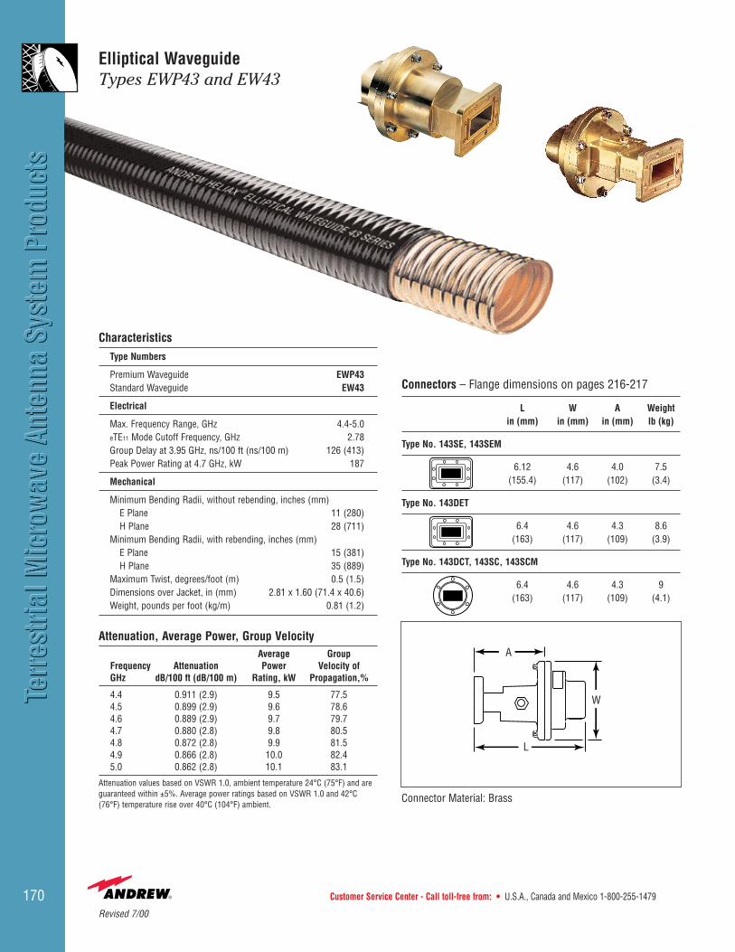
Customer Service Center - Call toll-free from: • U.S.A., Canada and Mexico 1-800-255-1479170
Connectors – Flange dimensions on pages 216-217
L W A Weightin (mm) in (mm) in (mm) lb (kg)
Type No. 143SE, 143SEM
6.12 4.6 4.0 7.5(155.4) (117) (102) (3.4)
Type No. 143DET
6.4 4.6 4.3 8.6(163) (117) (109) (3.9)
Type No. 143DCT, 143SC, 143SCM
6.4 4.6 4.3 9(163) (117) (109) (4.1)
A
L
W
CharacteristicsType Numbers
Premium Waveguide EWP43Standard Waveguide EW43
Electrical
Max. Frequency Range, GHz 4.4-5.0eTE11 Mode Cutoff Frequency, GHz 2.78Group Delay at 3.95 GHz, ns/100 ft (ns/100 m) 126 (413)Peak Power Rating at 4.7 GHz, kW 187
Mechanical
Minimum Bending Radii, without rebending, inches (mm)E Plane 11 (280)H Plane 28 (711)
Minimum Bending Radii, with rebending, inches (mm)E Plane 15 (381)H Plane 35 (889)
Maximum Twist, degrees/foot (m) 0.5 (1.5)Dimensions over Jacket, in (mm) 2.81 x 1.60 (71.4 x 40.6)Weight, pounds per foot (kg/m) 0.81 (1.2)
Attenuation, Average Power, Group VelocityAverage Group
Frequency Attenuation Power Velocity ofGHz dB/100 ft (dB/100 m) Rating, kW Propagation,%
4.4 0.911 (2.9) 9.5 77.54.5 0.899 (2.9) 9.6 78.64.6 0.889 (2.9) 9.7 79.74.7 0.880 (2.8) 9.8 80.54.8 0.872 (2.8) 9.9 81.54.9 0.866 (2.8) 10.0 82.45.0 0.862 (2.8) 10.1 83.1
Attenuation values based on VSWR 1.0, ambient temperature 24°C (75°F) and areguaranteed within ±5%. Average power ratings based on VSWR 1.0 and 42°C(76°F) temperature rise over 40°C (104°F) ambient.
Elliptical WaveguideTypes EWP43 and EW43
Connector Material: Brass
Revised 7/00
• U.K. 0800-250055 • Australia 1800-803 219 • New Zealand 0800-441-747 Visit us at: www.andrew.com 171
Ordering Information for Waveguide AssembliesFrequency Waveguide Flange Connector† Flex-Twist
GHz* Type Type†† Tunable Pre-Tuned Pressure Window 2 ft (0.6 m)
Premium Waveguide Assemblies VSWR 1.07 (29.4)**
4.4–5.0 EWP43 UG-149/U††† 143DCT 143SC 55000A-187 F187PA0240BACPR187G 143DET 143SE 55001-187 F187PA0240CAPDR48 – 143SEM 223306-48 F187MH0600HAPAR48 – 143SCM
Standard Waveguide Assemblies VSWR 1.15 (23.1)**
4.4–5.0 EW43 UG-149/U††† – 143SC 223306-48 F187MH0600HSCPR187G – 143SE 55001-187 F187PA0240CSPDR48 – 143SEMPAR48 – 143SCM
* Contact Andrew for information on other frequency bands.** VSWR max., (R.L., dB). Up to 300 ft (90 m). The indicated maximum VSWR characteristics are guaranteed for factory assemblies and are typical for field assemblies.† “Pre-tuned” connectors are for field attachment only. “Tunable” connectors ordered with factory assemblies are factory tuned. †† For detailed information on mating flanges, refer to pages 214-218.††† Modified cover flange with gasket groove. Mates with UG choke or cover flanges.
Description Type No.
Hangers and Adapters
Hanger Kit of 10, Recommended maximum spacingfor outdoor installation is 4 ft (1.22 m)* 42396A-16Hardware Kit of 10, 3/8" bolts, lock washers, nuts
3/4" (19 mm) long 31769-51" (25 mm) long 31769-1
Angle Adapter Kit of 10. Stainless steel 31768ARound Member Adapter Kit of 10. Stainless steelMember Diameter, in (mm)
1-2 (25-50) 31670-12-3 (50-75) 31670-23-4 (75-100) 31670-34-5 (100-125) 31670-45-6 (125-150) 31670-5
45° Adapter Kit of 10. Galvanized steel 42334Threaded Rod Support, 3/8” rod, nuts, washers, ceiling bracket
12 in (305 mm) long, kit of 1 3177112 in (305 mm) long, kit of 5 31771-424 in (610 mm) long, kit of 1 31771-924 in (610 mm) long, kit of 5 31771-6
Tower Standoff Kit of 10. 1 in (25 mm) standoffMember Diameter, in (mm)
0.75-1.5 (20-40) 30848-51.5-3.0 (40-75) 30848-43-4 (75-100) 30848-14-5 (100-125) 30848-25-6 (125-150) 30848-3
Tower Standoff Kit of 10. 2.5 in (60 mm) standoffMember Diameter, in (mm)
3-4 (75-100) 41108A-14-5 (100-125) 41108A-25-6 (125-150) 41108A-3
* Standard conditions: 125 mph (200 km/h) survival wind velocity, 0.5 in (13 mm) radial ice. For other conditions see page 196.
Description Type No.
Other Accessories
Flaring Tool Kit for connector attachment EWFTK-43Splice 143DZGrounding Kit with factory attached, one-hole lug 204989-10Grounding Kit with field attachable crimp-on, one-hole lug 204989-28Crimping Tool to field attach lug to Grounding Kit 207270Hoisting Grip 31535Bending Tool Kit. One each E and H Plane tool EWBTK-3Connector Reattachment Kit 33544-45Wall-Roof Feed Thru 245314-43Waveguide Boot for Plates (below),
4 in (102 mm) dia. WGB4-435 in (127 mm) dia. WGB5-43
Feed-Thru Plate for Boots (above)
Openings For 4 in Boots
1 204673-11 204673-24 204673-48 204673-8
Accessories – Photos and detailed descriptions on pages 194-200
Revised 7/00 & 5/01
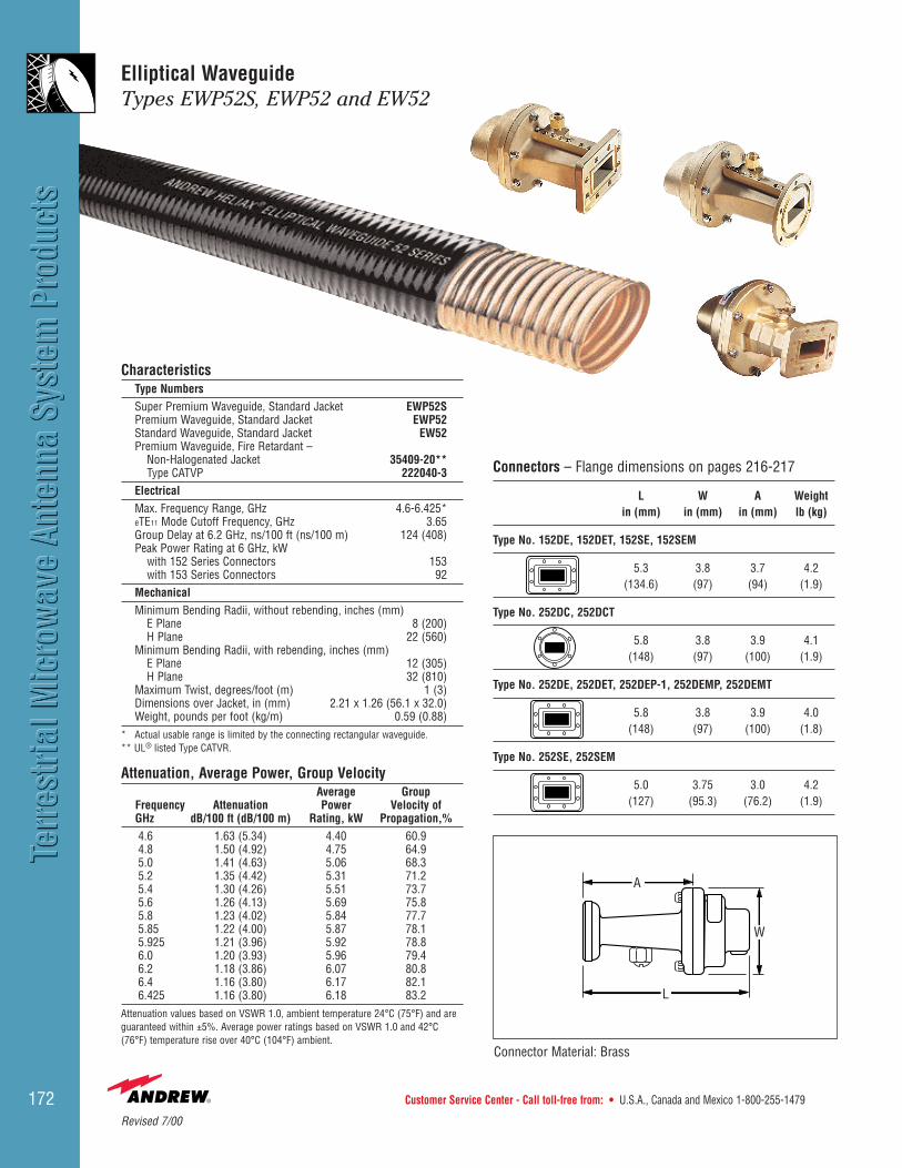
Customer Service Center - Call toll-free from: • U.S.A., Canada and Mexico 1-800-255-1479172
Connectors – Flange dimensions on pages 216-217
L W A Weightin (mm) in (mm) in (mm) lb (kg)
Type No. 152DE, 152DET, 152SE, 152SEM
5.3 3.8 3.7 4.2(134.6) (97) (94) (1.9)
Type No. 252DC, 252DCT
5.8 3.8 3.9 4.1(148) (97) (100) (1.9)
Type No. 252DE, 252DET, 252DEP-1, 252DEMP, 252DEMT
5.8 3.8 3.9 4.0(148) (97) (100) (1.8)
Type No. 252SE, 252SEM
5.0 3.75 3.0 4.2(127) (95.3) (76.2) (1.9)
Elliptical WaveguideTypes EWP52S, EWP52 and EW52
A
L
W
Connector Material: Brass
CharacteristicsType NumbersSuper Premium Waveguide, Standard Jacket EWP52SPremium Waveguide, Standard Jacket EWP52Standard Waveguide, Standard Jacket EW52Premium Waveguide, Fire Retardant –
Non-Halogenated Jacket 35409-20**Type CATVP 222040-3
ElectricalMax. Frequency Range, GHz 4.6-6.425*eTE11 Mode Cutoff Frequency, GHz 3.65Group Delay at 6.2 GHz, ns/100 ft (ns/100 m) 124 (408)Peak Power Rating at 6 GHz, kW
with 152 Series Connectors 153with 153 Series Connectors 92
MechanicalMinimum Bending Radii, without rebending, inches (mm)
E Plane 8 (200)H Plane 22 (560)
Minimum Bending Radii, with rebending, inches (mm)E Plane 12 (305)H Plane 32 (810)
Maximum Twist, degrees/foot (m) 1 (3)Dimensions over Jacket, in (mm) 2.21 x 1.26 (56.1 x 32.0)Weight, pounds per foot (kg/m) 0.59 (0.88)
* Actual usable range is limited by the connecting rectangular waveguide.** UL® listed Type CATVR.
Attenuation, Average Power, Group VelocityAverage Group
Frequency Attenuation Power Velocity ofGHz dB/100 ft (dB/100 m) Rating, kW Propagation,%4.6 1.63 (5.34) 4.40 60.94.8 1.50 (4.92) 4.75 64.95.0 1.41 (4.63) 5.06 68.35.2 1.35 (4.42) 5.31 71.25.4 1.30 (4.26) 5.51 73.75.6 1.26 (4.13) 5.69 75.85.8 1.23 (4.02) 5.84 77.75.85 1.22 (4.00) 5.87 78.15.925 1.21 (3.96) 5.92 78.86.0 1.20 (3.93) 5.96 79.46.2 1.18 (3.86) 6.07 80.86.4 1.16 (3.80) 6.17 82.16.425 1.16 (3.80) 6.18 83.2
Attenuation values based on VSWR 1.0, ambient temperature 24°C (75°F) and areguaranteed within ±5%. Average power ratings based on VSWR 1.0 and 42°C(76°F) temperature rise over 40°C (104°F) ambient.
Revised 7/00
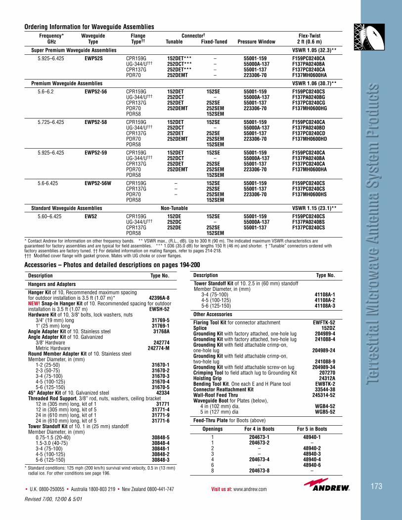
• U.K. 0800-250055 • Australia 1800-803 219 • New Zealand 0800-441-747 Visit us at: www.andrew.com 173
Ordering Information for Waveguide AssembliesFrequency* Waveguide Flange Connector† Flex-Twist
GHz Type Type†† Tunable Fixed-Tuned Pressure Window 2 ft (0.6 m)
Super Premium Waveguide Assemblies VSWR 1.05 (32.3)**
5.925–6.425 EWP52S CPR159G 152DET*** – 55001-159 F159PC0240CAUG-344/U††† 252DCT*** – 55000A-137 F137PA0240BACPR137G 252DET*** – 55001-137 F137PC0240CAPDR70 252DEMT – 223306-70 F137MH0600HA
Premium Waveguide Assemblies VSWR 1.06 (30.7)**
5.6–6.2 EWP52-56 CPR159G 152DET 152SE 55001-159 F159PC0240CSUG-344/U††† 252DCT – 55000A-137 F137PA0240BGCPR137G 252DET 252SE 55001-137 F137PC0240CGPDR70 252DEMT 252SEM 223306-70 F137MH0600HGPDR58 152SEM
5.725–6.425 EWP52-58 CPR159G 152DET 152SE 55001-159 F159PC0240CAUG-344/U††† 252DCT – 55000A-137 F137PA0240BDCPR137G 252DET 252SE 55001-137 F137PC0240CDPDR70 252DEMT 252SEM 223306-70 F137MH0600HDPDR58 152SEM
5.925–6.425 EWP52-59 CPR159G 152DET 152SE 55001-159 F159PC0240CAUG-344/U††† 252DCT – 55000A-137 F137PA0240BACPR137G 252DET 252SE 55001-137 F137PC0240CAPDR70 252DEMT 252SEM 223306-70 F137MH0600HAPDR58 152SEM
5.6-6.425 EWP52-56W CPR159G – 152SE 55001-159 F159PC0240CSCPR137G – 252SE 55001-137 F137PC0240CSPDR70 – 252SEM 223306-70 F137MH0600HSPDR58 152SEM
Standard Waveguide Assemblies Non-Tunable VSWR 1.15 (23.1)**
5.60–6.425 EW52 CPR159G 152DE 152SE 55001-159 F159PC0240CSUG-344/U††† 252DC – 55000A-137 F137PA0240BSCPR137G 252DE 252SE 55001-137 F137PC0240CSPDR58 152SEM
* Contact Andrew for information on other frequency bands. ** VSWR max., (R.L., dB). Up to 300 ft (90 m). The indicated maximum VSWR characteristics are guaranteed for factory assemblies and are typical for field assemblies. *** 1.036 (35.0 dB) for lengths 150 ft (46 m) and shorter. † “Tunable” connectors ordered with factory assemblies are factory tuned. †† For detailed information on mating flanges, refer to pages 214-218.††† Modified cover flange with gasket groove. Mates with UG choke or cover flanges.
Description Type No.
Hangers and Adapters
Hanger Kit of 10, Recommended maximum spacingfor outdoor installation is 3.5 ft (1.07 m)* 42396A-8NEW! Snap-In Hanger Kit of 10. Recommended spacing for outdoor installation is 3.5 ft (1.07 m) EWSH-52Hardware Kit of 10, 3/8" bolts, lock washers, nuts
3/4" (19 mm) long 31769-51" (25 mm) long 31769-1
Angle Adapter Kit of 10. Stainless steel 31768AAngle Adapter Kit of 10. Galvanized
3/8" Hardware 242774Metric Hardware 242774-M
Round Member Adapter Kit of 10. Stainless steelMember Diameter, in (mm)
1-2 (25-50) 31670-12-3 (50-75) 31670-23-4 (75-100) 31670-34-5 (100-125) 31670-45-6 (125-150) 31670-5
45° Adapter Kit of 10. Galvanized steel 42334Threaded Rod Support, 3/8” rod, nuts, washers, ceiling bracket
12 in (305 mm) long, kit of 1 3177112 in (305 mm) long, kit of 5 31771-424 in (610 mm) long, kit of 1 31771-924 in (610 mm) long, kit of 5 31771-6
Tower Standoff Kit of 10. 1 in (25 mm) standoffMember Diameter, in (mm)
0.75-1.5 (20-40) 30848-51.5-3.0 (40-75) 30848-43-4 (75-100) 30848-14-5 (100-125) 30848-25-6 (125-150) 30848-3
* Standard conditions: 125 mph (200 km/h) survival wind velocity, 0.5 in (13 mm) radial ice. For other conditions see page 196.
Description Type No.
Tower Standoff Kit of 10. 2.5 in (60 mm) standoffMember Diameter, in (mm)
3-4 (75-100) 41108A-14-5 (100-125) 41108A-25-6 (125-150) 41108A-3
Other Accessories
Flaring Tool Kit for connector attachment EWFTK-52Splice 152DZGrounding Kit with factory attached, one-hole lug 204989-4Grounding Kit with factory attached, two-hole lug 241088-4Grounding Kit with field attachable crimp-on, one-hole lug 204989-24Grounding Kit with field attachable crimp-on, two-hole lug 241088-9Grounding Kit with field attachable screw-on lug 204989-34Crimping Tool to field attach lug to Grounding Kit 207270Hoisting Grip 24312ABending Tool Kit. One each E and H Plane tool EWBTK-2Connector Reattachment Kit 33544-38Wall-Roof Feed Thru 245314-52Waveguide Boot for Plates (below),
4 in (102 mm) dia. WGB4-525 in (127 mm) dia WGB5-52
Feed-Thru Plate for Boots (above)
Openings For 4 in Boots For 5 in Boots
1 204673-1 48940-11 204673-2 –2 – 48940-23 – 48940-34 204673-4 48940-46 – 48940-68 204673-8 –
Accessories – Photos and detailed descriptions on pages 194-200
Revised 7/00, 12/00 & 5/01
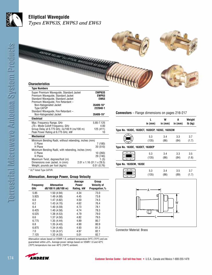
Customer Service Center - Call toll-free from: • U.S.A., Canada and Mexico 1-800-255-1479174
CharacteristicsType NumbersSuper Premium Waveguide, Standard Jacket EWP63SPremium Waveguide, Standard Jacket EWP63Standard Waveguide, Standard Jacket EW63Premium Waveguide, Fire Retardant –
Non-Halogenated Jacket 35409-18*Type CATVP 222040-1
Standard Waveguide, Fire Retardant –Non-Halogenated Jacket 35409-19*
ElectricalMax. Frequency Range, GHz 5.85-7.125eTE11 Mode Cutoff Frequency, GHz 4.00Group Delay at 6.775 GHz, ns/100 ft (ns/100 m) 125 (411)Peak Power Rating at 6.775 GHz, kW 10MechanicalMinimum Bending Radii, without rebending, inches (mm)
E Plane 7 (180)H Plane 20 (510)
Minimum Bending Radii, with rebending, inches (mm)E Plane 10 (260)H Plane 29 (740)
Maximum Twist, degrees/foot (m) 1 (3)Dimensions over Jacket, in (mm) 2.01 x 1.16 (51.1 x 29.5)Weight, pounds per foot (kg/m) 0.51 (0.76)
* UL® listed Type CATVR.
Attenuation, Average Power, Group VelocityAverage Group
Frequency Attenuation Power Velocity ofGHz dB/100 ft (dB/100 m) Rating, kW Propagation,%
5.85 1.50 (4.94) 4.34 73.05.925 1.49 (4.88) 4.45 73.86.0 1.47 (4.82) 4.50 74.56.2 1.43 (4.70) 4.62 76.46.4 1.40 (4.59) 4.73 78.16.425 1.40 (4.58) 4.74 78.36.525 1.38 (4.53) 4.79 79.06.6 1.37 (4.50) 4.82 79.56.775 1.35 (4.44) 4.89 80.76.8 1.35 (4.43) 4.90 80.96.875 1.34 (4.40) 4.93 81.37.0 1.33 (4.37) 4.97 82.17.125 1.32 (4.33) 5.01 82.7
Attenuation values based on VSWR 1.0, ambient temperature 24°C (75°F) and areguaranteed within ±5%. Average power ratings based on VSWR 1.0 and 42°C(76°F) temperature rise over 40°C (104°F) ambient.
Elliptical WaveguideTypes EWP63S, EWP63 and EW63
Connectors – Flange dimensions on pages 216-217
L W A Weightin (mm) in (mm) in (mm) lb (kg)
Type No. 163DC, 163DCT, 163DCP, 163SC, 163SCM
5.3 3.4 3.3 3.7(135) (86) (84) (1.7)
Type No. 163DE, 163DET, 163DEP
5.3 3.4 3.3 3.5(135) (86) (84) (1.6)
Type No. 163SEM, 163SE
5.3 3.4 3.5 3.7(135) (86) (89) (1.7)
A
L
W
Connector Material: Brass
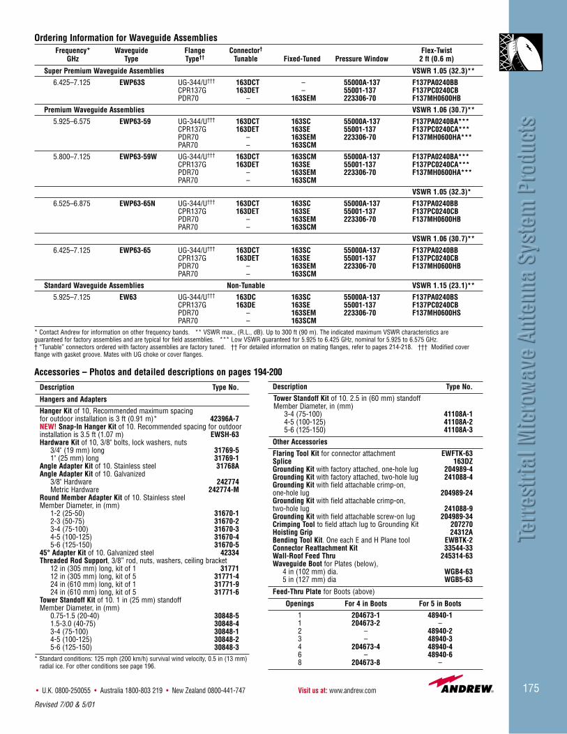
• U.K. 0800-250055 • Australia 1800-803 219 • New Zealand 0800-441-747 Visit us at: www.andrew.com 175
Ordering Information for Waveguide AssembliesFrequency* Waveguide Flange Connector† Flex-Twist
GHz Type Type†† Tunable Fixed-Tuned Pressure Window 2 ft (0.6 m)
Super Premium Waveguide Assemblies VSWR 1.05 (32.3)**
6.425–7.125 EWP63S UG-344/U††† 163DCT – 55000A-137 F137PA0240BBCPR137G 163DET – 55001-137 F137PC0240CBPDR70 – 163SEM 223306-70 F137MH0600HB
Premium Waveguide Assemblies VSWR 1.06 (30.7)**
5.925–6.575 EWP63-59 UG-344/U††† 163DCT 163SC 55000A-137 F137PA0240BA***CPR137G 163DET 163SE 55001-137 F137PC0240CA***PDR70 – 163SEM 223306-70 F137MH0600HA***PAR70 – 163SCM
5.800–7.125 EWP63-59W UG-344/U††† 163DCT 163SCM 55000A-137 F137PA0240BA***CPR137G 163DET 163SE 55001-137 F137PC0240CA***PDR70 – 163SEM 223306-70 F137MH0600HA***PAR70 – 163SCM
VSWR 1.05 (32.3)*
6.525–6.875 EWP63-65N UG-344/U††† 163DCT 163SC 55000A-137 F137PA0240BBCPR137G 163DET 163SE 55001-137 F137PC0240CBPDR70 – 163SEM 223306-70 F137MH0600HBPAR70 – 163SCM
VSWR 1.06 (30.7)**
6.425–7.125 EWP63-65 UG-344/U††† 163DCT 163SC 55000A-137 F137PA0240BBCPR137G 163DET 163SE 55001-137 F137PC0240CBPDR70 – 163SEM 223306-70 F137MH0600HBPAR70 – 163SCM
Standard Waveguide Assemblies Non-Tunable VSWR 1.15 (23.1)**
5.925–7.125 EW63 UG-344/U††† 163DC 163SC 55000A-137 F137PA0240BSCPR137G 163DE 163SE 55001-137 F137PC0240CBPDR70 – 163SEM 223306-70 F137MH0600HSPAR70 – 163SCM
* Contact Andrew for information on other frequency bands. ** VSWR max., (R.L., dB). Up to 300 ft (90 m). The indicated maximum VSWR characteristics are guaranteed for factory assemblies and are typical for field assemblies. *** Low VSWR guaranteed for 5.925 to 6.425 GHz, nominal for 5.925 to 6.575 GHz. † “Tunable” connectors ordered with factory assemblies are factory tuned. †† For detailed information on mating flanges, refer to pages 214-218. ††† Modified coverflange with gasket groove. Mates with UG choke or cover flanges.
Description Type No.
Hangers and Adapters
Hanger Kit of 10, Recommended maximum spacingfor outdoor installation is 3 ft (0.91 m)* 42396A-7NEW! Snap-In Hanger Kit of 10. Recommended spacing for outdoor installation is 3.5 ft (1.07 m) EWSH-63Hardware Kit of 10, 3/8" bolts, lock washers, nuts
3/4" (19 mm) long 31769-51" (25 mm) long 31769-1
Angle Adapter Kit of 10. Stainless steel 31768AAngle Adapter Kit of 10. Galvanized
3/8" Hardware 242774Metric Hardware 242774-M
Round Member Adapter Kit of 10. Stainless steelMember Diameter, in (mm)
1-2 (25-50) 31670-12-3 (50-75) 31670-23-4 (75-100) 31670-34-5 (100-125) 31670-45-6 (125-150) 31670-5
45° Adapter Kit of 10. Galvanized steel 42334Threaded Rod Support, 3/8” rod, nuts, washers, ceiling bracket
12 in (305 mm) long, kit of 1 3177112 in (305 mm) long, kit of 5 31771-424 in (610 mm) long, kit of 1 31771-924 in (610 mm) long, kit of 5 31771-6
Tower Standoff Kit of 10. 1 in (25 mm) standoffMember Diameter, in (mm)
0.75-1.5 (20-40) 30848-51.5-3.0 (40-75) 30848-43-4 (75-100) 30848-14-5 (100-125) 30848-25-6 (125-150) 30848-3
* Standard conditions: 125 mph (200 km/h) survival wind velocity, 0.5 in (13 mm) radial ice. For other conditions see page 196.
Description Type No.
Tower Standoff Kit of 10. 2.5 in (60 mm) standoffMember Diameter, in (mm)
3-4 (75-100) 41108A-14-5 (100-125) 41108A-25-6 (125-150) 41108A-3
Other Accessories
Flaring Tool Kit for connector attachment EWFTK-63Splice 163DZGrounding Kit with factory attached, one-hole lug 204989-4Grounding Kit with factory attached, two-hole lug 241088-4Grounding Kit with field attachable crimp-on, one-hole lug 204989-24Grounding Kit with field attachable crimp-on, two-hole lug 241088-9Grounding Kit with field attachable screw-on lug 204989-34Crimping Tool to field attach lug to Grounding Kit 207270Hoisting Grip 24312ABending Tool Kit. One each E and H Plane tool EWBTK-2Connector Reattachment Kit 33544-33Wall-Roof Feed Thru 245314-63Waveguide Boot for Plates (below),
4 in (102 mm) dia. WGB4-635 in (127 mm) dia WGB5-63
Feed-Thru Plate for Boots (above)
Openings For 4 in Boots For 5 in Boots
1 204673-1 48940-11 204673-2 –2 – 48940-23 – 48940-34 204673-4 48940-46 – 48940-68 204673-8 –
Accessories – Photos and detailed descriptions on pages 194-200
Revised 7/00 & 5/01
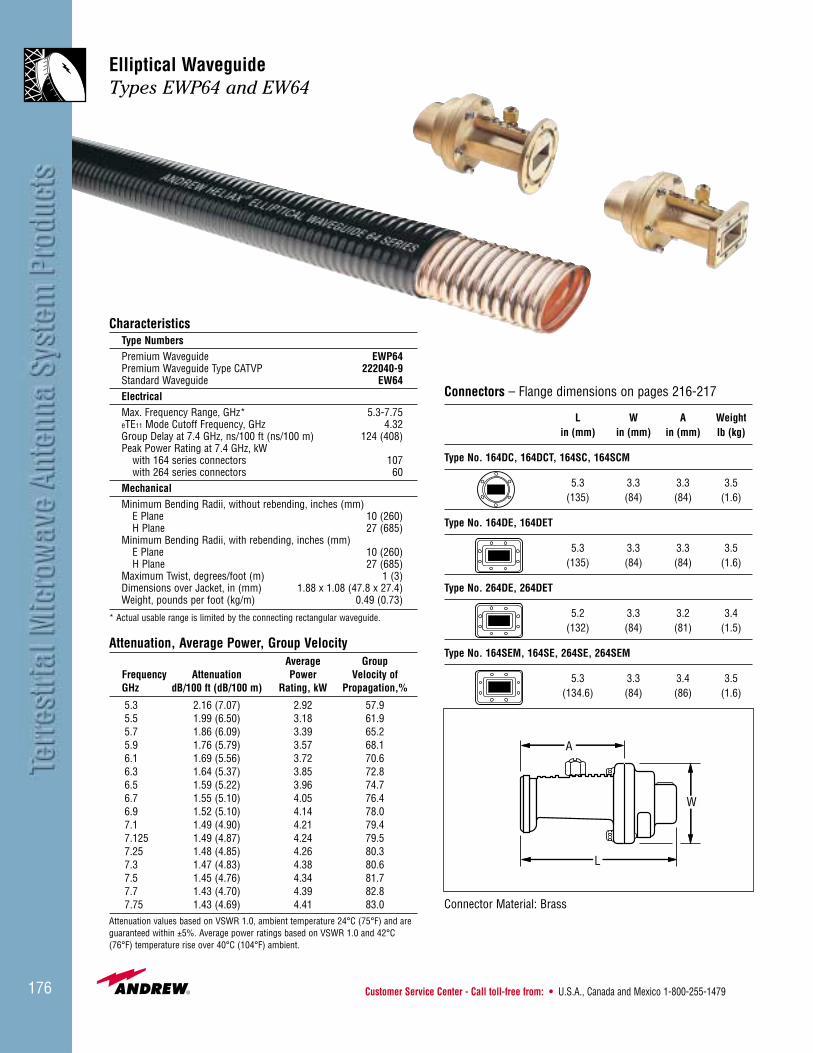
Customer Service Center - Call toll-free from: • U.S.A., Canada and Mexico 1-800-255-1479176
Connectors – Flange dimensions on pages 216-217
L W A Weightin (mm) in (mm) in (mm) lb (kg)
Type No. 164DC, 164DCT, 164SC, 164SCM
5.3 3.3 3.3 3.5(135) (84) (84) (1.6)
Type No. 164DE, 164DET
5.3 3.3 3.3 3.5(135) (84) (84) (1.6)
Type No. 264DE, 264DET
5.2 3.3 3.2 3.4(132) (84) (81) (1.5)
Type No. 164SEM, 164SE, 264SE, 264SEM
5.3 3.3 3.4 3.5(134.6) (84) (86) (1.6)
Elliptical WaveguideTypes EWP64 and EW64
CharacteristicsType NumbersPremium Waveguide EWP64Premium Waveguide Type CATVP 222040-9Standard Waveguide EW64ElectricalMax. Frequency Range, GHz* 5.3-7.75eTE11 Mode Cutoff Frequency, GHz 4.32Group Delay at 7.4 GHz, ns/100 ft (ns/100 m) 124 (408)Peak Power Rating at 7.4 GHz, kW
with 164 series connectors 107with 264 series connectors 60
MechanicalMinimum Bending Radii, without rebending, inches (mm)
E Plane 10 (260)H Plane 27 (685)
Minimum Bending Radii, with rebending, inches (mm)E Plane 10 (260)H Plane 27 (685)
Maximum Twist, degrees/foot (m) 1 (3)Dimensions over Jacket, in (mm) 1.88 x 1.08 (47.8 x 27.4)Weight, pounds per foot (kg/m) 0.49 (0.73)
* Actual usable range is limited by the connecting rectangular waveguide.
Attenuation, Average Power, Group VelocityAverage Group
Frequency Attenuation Power Velocity ofGHz dB/100 ft (dB/100 m) Rating, kW Propagation,%
5.3 2.16 (7.07) 2.92 57.95.5 1.99 (6.50) 3.18 61.95.7 1.86 (6.09) 3.39 65.25.9 1.76 (5.79) 3.57 68.16.1 1.69 (5.56) 3.72 70.66.3 1.64 (5.37) 3.85 72.86.5 1.59 (5.22) 3.96 74.76.7 1.55 (5.10) 4.05 76.46.9 1.52 (5.10) 4.14 78.07.1 1.49 (4.90) 4.21 79.47.125 1.49 (4.87) 4.24 79.57.25 1.48 (4.85) 4.26 80.37.3 1.47 (4.83) 4.38 80.67.5 1.45 (4.76) 4.34 81.77.7 1.43 (4.70) 4.39 82.87.75 1.43 (4.69) 4.41 83.0
Attenuation values based on VSWR 1.0, ambient temperature 24°C (75°F) and areguaranteed within ±5%. Average power ratings based on VSWR 1.0 and 42°C(76°F) temperature rise over 40°C (104°F) ambient.
A
L
W
Connector Material: Brass
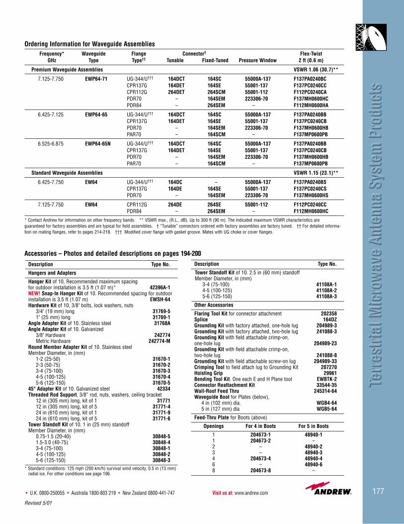
• U.K. 0800-250055 • Australia 1800-803 219 • New Zealand 0800-441-747 Visit us at: www.andrew.com 177
Ordering Information for Waveguide AssembliesFrequency* Waveguide Flange Connector† Flex-Twist
GHz Type Type†† Tunable Fixed-Tuned Pressure Window 2 ft (0.6 m)
Premium Waveguide Assemblies VSWR 1.06 (30.7)**
7.125-7.750 EWP64-71 UG-344/U††† 164DCT 164SC 55000A-137 F137PA0240BCCPR137G 164DET 164SE 55001-137 F137PC0240CCCPR112G 264DET 264SCM 55001-112 F112PC0240CAPDR70 – 164SEM 223306-70 F137MH0600HCPDR84 – 264SEM – F112MH0600HA
6.425-7.125 EWP64-65 UG-344/U††† 164DCT 164SC 55000A-137 F137PA0240BBCPR137G 164DET 164SE 55001-137 F137PC0240CBPDR70 – 164SEM 223306-70 F137MH0600HBPAR70 – 164SCM – F137MP0600PB
6.525-6.875 EWP64-65N UG-344/U††† 164DCT 164SC 55000A-137 F137PA0240BBCPR137G 164DET 164SE 55001-137 F137PC0240CBPDR70 – 164SEM 223306-70 F137MH0600HBPAR70 – 164SCM – F137MP0600PB
Standard Waveguide Assemblies VSWR 1.15 (23.1)**
6.425-7.750 EW64 UG-344/U††† 164DC – 55000A-137 F137PA0240BSCPR137G 164DE 164SE 55001-137 F137PC0240CSPDR70 – 164SEM 223306-70 F137MH0600HS
7.125-7.750 EW64 CPR112G 264DE 264SE 55001-112 F112PC0240CCPDR84 – 264SEM – F112MH0600HC
* Contact Andrew for information on other frequency bands. ** VSWR max., (R.L., dB). Up to 300 ft (90 m). The indicated maximum VSWR characteristics are guaranteed for factory assemblies and are typical for field assemblies. † “Tunable” connectors ordered with factory assemblies are factory tuned. †† For detailed informa-tion on mating flanges, refer to pages 214-218. ††† Modified cover flange with gasket groove. Mates with UG choke or cover flanges.
Description Type No.
Hangers and Adapters
Hanger Kit of 10, Recommended maximum spacingfor outdoor installation is 3.5 ft (1.07 m)* 42396A-1NEW! Snap-In Hanger Kit of 10. Recommended spacing for outdoor installation is 3.5 ft (1.07 m) EWSH-64Hardware Kit of 10, 3/8" bolts, lock washers, nuts
3/4" (19 mm) long 31769-51" (25 mm) long 31769-1
Angle Adapter Kit of 10. Stainless steel 31768AAngle Adapter Kit of 10. Galvanized
3/8" Hardware 242774Metric Hardware 242774-M
Round Member Adapter Kit of 10. Stainless steelMember Diameter, in (mm)
1-2 (25-50) 31670-12-3 (50-75) 31670-23-4 (75-100) 31670-34-5 (100-125) 31670-45-6 (125-150) 31670-5
45° Adapter Kit of 10. Galvanized steel 42334Threaded Rod Support, 3/8” rod, nuts, washers, ceiling bracket
12 in (305 mm) long, kit of 1 3177112 in (305 mm) long, kit of 5 31771-424 in (610 mm) long, kit of 1 31771-924 in (610 mm) long, kit of 5 31771-6
Tower Standoff Kit of 10. 1 in (25 mm) standoffMember Diameter, in (mm)
0.75-1.5 (20-40) 30848-51.5-3.0 (40-75) 30848-43-4 (75-100) 30848-14-5 (100-125) 30848-25-6 (125-150) 30848-3
* Standard conditions: 125 mph (200 km/h) survival wind velocity, 0.5 in (13 mm) radial ice. For other conditions see page 196.
Description Type No.
Tower Standoff Kit of 10. 2.5 in (60 mm) standoffMember Diameter, in (mm)
3-4 (75-100) 41108A-14-5 (100-125) 41108A-25-6 (125-150) 41108A-3
Other Accessories
Flaring Tool Kit for connector attachment 202358Splice 164DZGrounding Kit with factory attached, one-hole lug 204989-3Grounding Kit with factory attached, two-hole lug 241088-3Grounding Kit with field attachable crimp-on, one-hole lug 204989-23Grounding Kit with field attachable crimp-on, two-hole lug 241088-8Grounding Kit with field attachable screw-on lug 204989-33Crimping Tool to field attach lug to Grounding Kit 207270Hoisting Grip 29961Bending Tool Kit. One each E and H Plane tool EWBTK-2Connector Reattachment Kit 33544-35Wall-Roof Feed Thru 245314-64Waveguide Boot for Plates (below),
4 in (102 mm) dia. WGB4-645 in (127 mm) dia WGB5-64
Feed-Thru Plate for Boots (above)
Openings For 4 in Boots For 5 in Boots
1 204673-1 48940-11 204673-2 –2 – 48940-23 – 48940-34 204673-4 48940-46 – 48940-68 204673-8 –
Accessories – Photos and detailed descriptions on pages 194-200
Revised 5/01
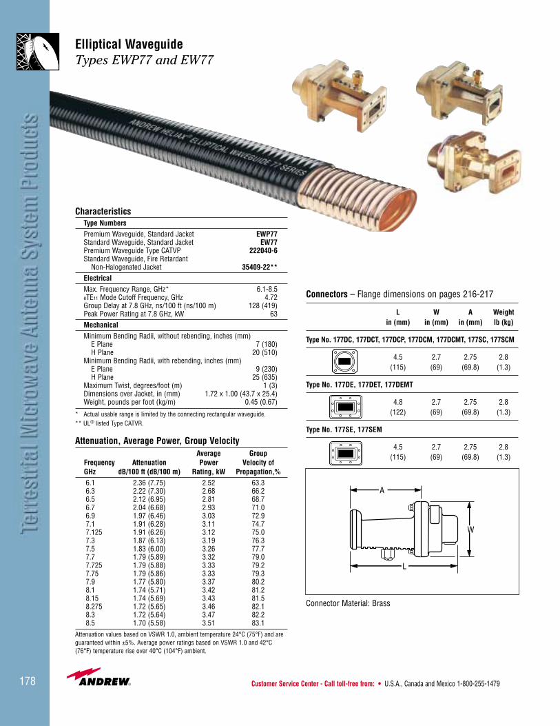
Customer Service Center - Call toll-free from: • U.S.A., Canada and Mexico 1-800-255-1479178
Connectors – Flange dimensions on pages 216-217
L W A Weightin (mm) in (mm) in (mm) lb (kg)
Type No. 177DC, 177DCT, 177DCP, 177DCM, 177DCMT, 177SC, 177SCM
4.5 2.7 2.75 2.8(115) (69) (69.8) (1.3)
Type No. 177DE, 177DET, 177DEMT
4.8 2.7 2.75 2.8(122) (69) (69.8) (1.3)
Type No. 177SE, 177SEM
4.5 2.7 2.75 2.8(115) (69) (69.8) (1.3)
Elliptical WaveguideTypes EWP77 and EW77
CharacteristicsType NumbersPremium Waveguide, Standard Jacket EWP77Standard Waveguide, Standard Jacket EW77Premium Waveguide Type CATVP 222040-6Standard Waveguide, Fire Retardant
Non-Halogenated Jacket 35409-22**ElectricalMax. Frequency Range, GHz* 6.1-8.5eTE11 Mode Cutoff Frequency, GHz 4.72Group Delay at 7.8 GHz, ns/100 ft (ns/100 m) 128 (419)Peak Power Rating at 7.8 GHz, kW 63MechanicalMinimum Bending Radii, without rebending, inches (mm)
E Plane 7 (180)H Plane 20 (510)
Minimum Bending Radii, with rebending, inches (mm)E Plane 9 (230)H Plane 25 (635)
Maximum Twist, degrees/foot (m) 1 (3)Dimensions over Jacket, in (mm) 1.72 x 1.00 (43.7 x 25.4)Weight, pounds per foot (kg/m) 0.45 (0.67)
* Actual usable range is limited by the connecting rectangular waveguide.** UL® listed Type CATVR.
Attenuation, Average Power, Group VelocityAverage Group
Frequency Attenuation Power Velocity ofGHz dB/100 ft (dB/100 m) Rating, kW Propagation,%6.1 2.36 (7.75) 2.52 63.36.3 2.22 (7.30) 2.68 66.26.5 2.12 (6.95) 2.81 68.76.7 2.04 (6.68) 2.93 71.06.9 1.97 (6.46) 3.03 72.97.1 1.91 (6.28) 3.11 74.77.125 1.91 (6.26) 3.12 75.07.3 1.87 (6.13) 3.19 76.37.5 1.83 (6.00) 3.26 77.77.7 1.79 (5.89) 3.32 79.07.725 1.79 (5.88) 3.33 79.27.75 1.79 (5.86) 3.33 79.37.9 1.77 (5.80) 3.37 80.28.1 1.74 (5.71) 3.42 81.28.15 1.74 (5.69) 3.43 81.58.275 1.72 (5.65) 3.46 82.18.3 1.72 (5.64) 3.47 82.28.5 1.70 (5.58) 3.51 83.1
Attenuation values based on VSWR 1.0, ambient temperature 24°C (75°F) and areguaranteed within ±5%. Average power ratings based on VSWR 1.0 and 42°C(76°F) temperature rise over 40°C (104°F) ambient.
Connector Material: Brass
L
A
W
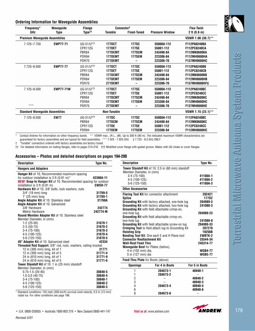
• U.K. 0800-250055 • Australia 1800-803 219 • New Zealand 0800-441-747 Visit us at: www.andrew.com 179
Ordering Information for Waveguide AssembliesFrequency* Waveguide Flange Connector† Flex-Twist
GHz Type Type†† Tunable Fixed-Tuned Pressure Window 2 ft (0.6 m)
Premium Waveguide Assemblies VSWR 1.06 (30.7)**
7.125–7.750 EWP77-71 UG-51/U††† 177DCT 177SC 55000A-112 F112PA0240BACPR112G 177DET 177SE 55001-112 F112PC0240CAPBR84 177DCMT 177SCM 243498-84 F112MK0600KAPDR84 177DEMT 177SEM 223306-84 F112MH0600HAPDR70 277DEMT – 223306-70 F137MH0600HC
7.725–8.500 EWP77-77 UG-51/U††† 177DCT 177SC 55000A-112 F112PA0240BBCPR112G 177DET 177SE 55001-112 F112PC0240CBPBR84 177DCMT 177SCM 243498-84 F112MK0600KBPDR84 177DEMT 177SEM 223306-84 F112MH0600HBPDR70 277DEMT – 223306-70 F137MH0600HF‡
7.125–8.500 EWP77-71W UG-51/U††† 177DCT 177SC 55000A-112 F112PA0240BCCPR112G 177DET 177SE 55001-112 F112PC0240CCPBR84 177DCMT 177SCM 243498-84 F112MK0600KCPDR84 177DEMT 177SEM 223306-84 F112MH0600HC
*** PDR70 277DEMT – 223306-70 F137MH0600HE
Standard Waveguide Assemblies Non-Tunable VSWR 1.15 (23.1)**
7.125–8.500 EW77 UG-51/U††† 177DC 177SC 55000A-112 F112PA0240BCPBR84 177DCM 177SCM 243498-84 F112MK0600KCCPR112G 177DE 177SE 55001-112 F112PC0240CCPDR84 177DEM 177SEM 223306-84 F112MH0600HC
* Contact Andrew for information on other frequency bands. ** VSWR max., (R.L., dB). Up to 300 ft (90 m). The indicated maximum VSWR characteristics are guaranteed for factory assemblies and are typical for field assemblies. *** 7.425 - 7.925 GHz ‡ 7.725 - 8.3 GHz ONLY
† “Tunable” connectors ordered with factory assemblies are factory tuned. †† For detailed information on mating flanges, refer to pages 214-218. ††† Modified cover flange with gasket groove. Mates with UG choke or cover flanges.
Description Type No.
Hangers and Adapters
Hanger Kit of 10, Recommended maximum spacingfor outdoor installation is 3 ft (0.91 m)* 42396A-11NEW! Snap-In Hanger Kit of 10. Recommended spacing for outdoor installation is 3 ft (0.91 m) EWSH-77Hardware Kit of 10, 3/8" bolts, lock washers, nuts
3/4" (19 mm) long 31769-51" (25 mm) long 31769-1
Angle Adapter Kit of 10. Stainless steel 31768AAngle Adapter Kit of 10. Galvanized
3/8" Hardware 242774Metric Hardware 242774-M
Round Member Adapter Kit of 10. Stainless steelMember Diameter, in (mm)
1-2 (25-50) 31670-12-3 (50-75) 31670-23-4 (75-100) 31670-34-5 (100-125) 31670-45-6 (125-150) 31670-5
45° Adapter Kit of 10. Galvanized steel 42334Threaded Rod Support, 3/8” rod, nuts, washers, ceiling bracket
12 in (305 mm) long, kit of 1 3177112 in (305 mm) long, kit of 5 31771-424 in (610 mm) long, kit of 1 31771-924 in (610 mm) long, kit of 5 31771-6
Tower Standoff Kit of 10. 1 in (25 mm) standoffMember Diameter, in (mm)
0.75-1.5 (20-40) 30848-51.5-3.0 (40-75) 30848-43-4 (75-100) 30848-14-5 (100-125) 30848-25-6 (125-150) 30848-3
* Standard conditions: 125 mph (200 km/h) survival wind velocity, 0.5 in (13 mm) radial ice. For other conditions see page 196.
Description Type No.
Tower Standoff Kit of 10. 2.5 in (60 mm) standoffMember Diameter, in (mm)
3-4 (75-100) 41108A-14-5 (100-125) 41108A-25-6 (125-150) 41108A-3
Other Accessories
Flaring Tool Kit for connector attachment 202421Splice 177DZGrounding Kit with factory attached, one-hole lug 204989-3Grounding Kit with factory attached, two-hole lug 241088-3Grounding Kit with field attachable crimp-on, one-hole lug 204989-23Grounding Kit with field attachable crimp-on, two-hole lug 241088-8Grounding Kit with field attachable screw-on lug 204989-33Crimping Tool to field attach lug to Grounding Kit 207270Hoisting Grip 19256BBending Tool Kit. One each E and H Plane tool EWBTK-2Connector Reattachment Kit 33544-34Wall-Roof Feed Thru 245314-77Waveguide Boot for Plates (below),
4 in (102 mm) dia. WGB4-775 in (127 mm) dia WGB5-77
Feed-Thru Plate for Boots (above)
Openings For 4 in Boots For 5 in Boots
1 204673-1 48940-11 204673-2 –2 – 48940-23 – 48940-34 204673-4 48940-46 – 48940-68 204673-8 –
Accessories – Photos and detailed descriptions on pages 194-200
Revised 5/01
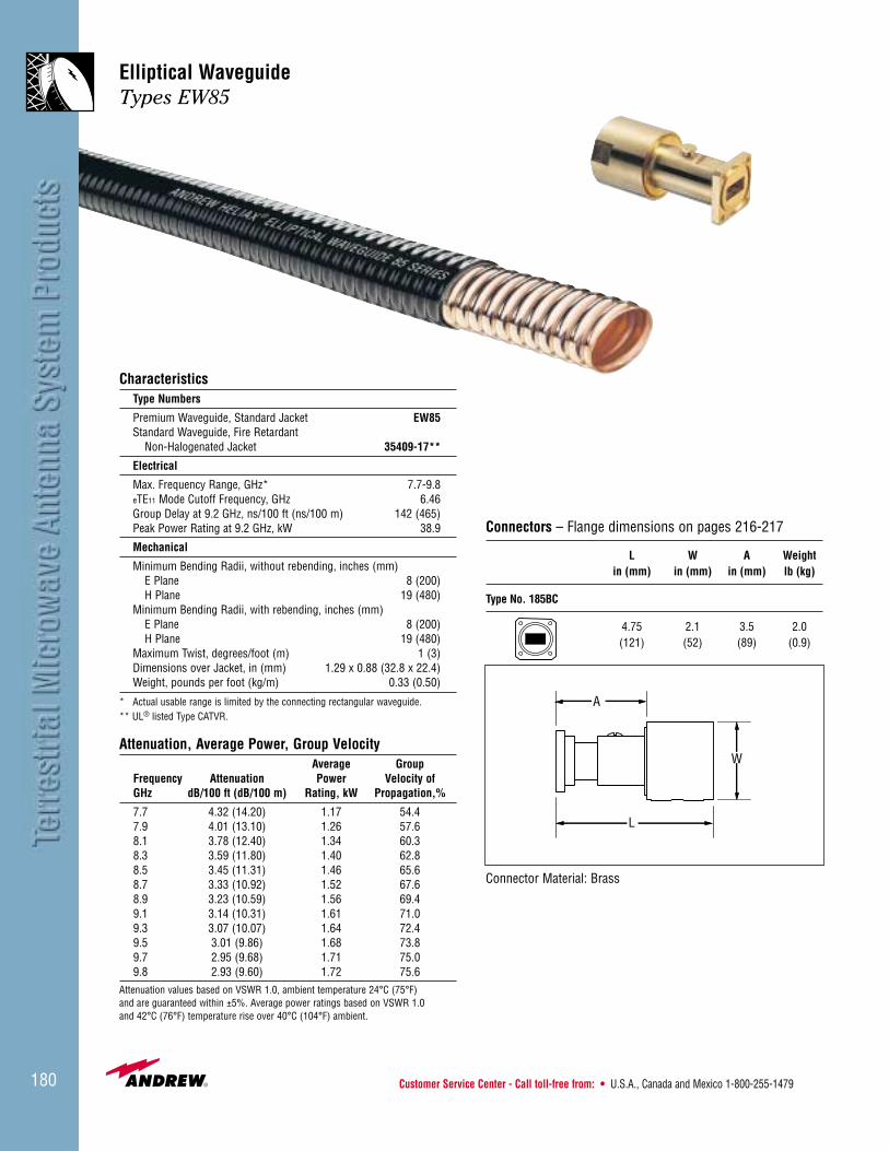
Customer Service Center - Call toll-free from: • U.S.A., Canada and Mexico 1-800-255-1479180
Connectors – Flange dimensions on pages 216-217
L W A Weightin (mm) in (mm) in (mm) lb (kg)
Type No. 185BC
4.75 2.1 3.5 2.0(121) (52) (89) (0.9)
Elliptical WaveguideTypes EW85
CharacteristicsType Numbers
Premium Waveguide, Standard Jacket EW85Standard Waveguide, Fire Retardant
Non-Halogenated Jacket 35409-17**
Electrical
Max. Frequency Range, GHz* 7.7-9.8eTE11 Mode Cutoff Frequency, GHz 6.46Group Delay at 9.2 GHz, ns/100 ft (ns/100 m) 142 (465)Peak Power Rating at 9.2 GHz, kW 38.9
Mechanical
Minimum Bending Radii, without rebending, inches (mm)E Plane 8 (200)H Plane 19 (480)
Minimum Bending Radii, with rebending, inches (mm)E Plane 8 (200)H Plane 19 (480)
Maximum Twist, degrees/foot (m) 1 (3)Dimensions over Jacket, in (mm) 1.29 x 0.88 (32.8 x 22.4)Weight, pounds per foot (kg/m) 0.33 (0.50)
* Actual usable range is limited by the connecting rectangular waveguide.** UL® listed Type CATVR.
Attenuation, Average Power, Group VelocityAverage Group
Frequency Attenuation Power Velocity ofGHz dB/100 ft (dB/100 m) Rating, kW Propagation,%
7.7 4.32 (14.20) 1.17 54.47.9 4.01 (13.10) 1.26 57.68.1 3.78 (12.40) 1.34 60.38.3 3.59 (11.80) 1.40 62.88.5 3.45 (11.31) 1.46 65.68.7 3.33 (10.92) 1.52 67.68.9 3.23 (10.59) 1.56 69.49.1 3.14 (10.31) 1.61 71.09.3 3.07 (10.07) 1.64 72.49.5 3.01 (9.86) 1.68 73.89.7 2.95 (9.68) 1.71 75.09.8 2.93 (9.60) 1.72 75.6
Attenuation values based on VSWR 1.0, ambient temperature 24°C (75°F) and are guaranteed within ±5%. Average power ratings based on VSWR 1.0 and 42°C (76°F) temperature rise over 40°C (104°F) ambient.
Connector Material: Brass
L
A
W
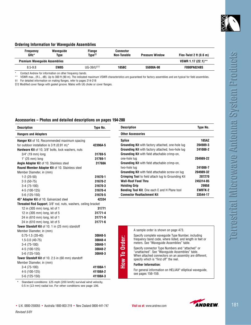
• U.K. 0800-250055 • Australia 1800-803 219 • New Zealand 0800-441-747 Visit us at: www.andrew.com 181
Ordering Information for Waveguide AssembliesFrequency Waveguide Flange Connector
GHz* Type Type†† Non-Tunable Pressure Window Flex-Twist 2 ft (0.6 m)
Premium Waveguide Assemblies VSWR 1.17 (22.1)**
8.5-9.8 EW85 UG-39/U††† 185BC 55000A-90 F090PA024BS
* Contact Andrew for information on other frequency bands. ** VSWR max., (R.L., dB). Up to 300 ft (90 m). The indicated maximum VSWR characteristics are guaranteed for factory assemblies and are typical for field assemblies.†† For detailed information on mating flanges, refer to pages 214-218††† Modified cover flange with gasket groove. Mates with UG choke or cover flanges.
Description Type No.
Hangers and Adapters
Hanger Kit of 10, Recommended maximum spacingfor outdoor installation is 3 ft (0.91 m)* 42396A-5Hardware Kit of 10, 3/8" bolts, lock washers, nuts
3/4" (19 mm) long 31769-51" (25 mm) long 31769-1
Angle Adapter Kit of 10. Stainless steel 31768ARound Member Adapter Kit of 10. Stainless steel Member Diameter, in (mm)
1-2 (25-50) 31670-12-3 (50-75) 31670-23-4 (75-100) 31670-34-5 (100-125) 31670-45-6 (125-150) 31670-5
45° Adapter Kit of 10. Galvanized steel 42334Threaded Rod Support, 3/8" rod, nuts, washers, ceiling bracket
12 in (305 mm) long, kit of 1 3177112 in (305 mm) long, kit of 5 31771-424 in (610 mm) long, kit of 1 31771-924 in (610 mm) long, kit of 5 31771-6
Tower Standoff Kit of 10. 1 in (25 mm) standoffMember Diameter, in (mm)
0.75-1.5 (20-40) 30848-51.5-3.0 (40-75) 30848-43-4 (75-100) 30848-14-5 (100-125) 30848-25-6 (125-150) 30848-3
Tower Standoff Kit of 10. 2.5 in (60 mm) standoffMember Diameter, in (mm)
3-4 (75-100) 41108A-14-5 (100-125) 41108A-25-6 (125-150) 41108A-3
* Standard conditions: 125 mph (200 km/h) survival wind velocity, 0.5 in (13 mm) radial ice. For other conditions see page 196.
Accessories – Photos and detailed descriptions on pages 194-200
Description Type No.
Other Accessories
Splice 185AZGrounding Kit with factory attached, one-hole lug 204989-3Grounding Kit with factory attached, two-hole lug 241088-2Grounding Kit with field attachable crimp-on, one-hole lug 204989-22Grounding Kit with field attachable crimp-on, two-hole lug 241088-7Grounding Kit with field attachable screw-on lug 204989-32Crimping Tool to field attach lug to Grounding Kit 207270Wall-Roof Feed Thru 245314-85Hoisting Grip 29958Bending Tool Kit. One each E and H Plane tool EWBTK-2Connector Reattachment Kit 33544-17
How
To
Orde
r:
A sample order is shown on page 473.
Specify complete waveguide Type Number, including frequency band code, where listed, and length in feet ormeters. See “Waveguide Assemblies” table.
Specify connector Type Numbers and “attached” or“unattached”. See “Waveguide Assemblies” table. When attached connectors on an assembly are different,specify which is “first off” the reel.
Further Information:
For general information on HELIAX® elliptical waveguide,see pages 156-159.
Revised 5/01
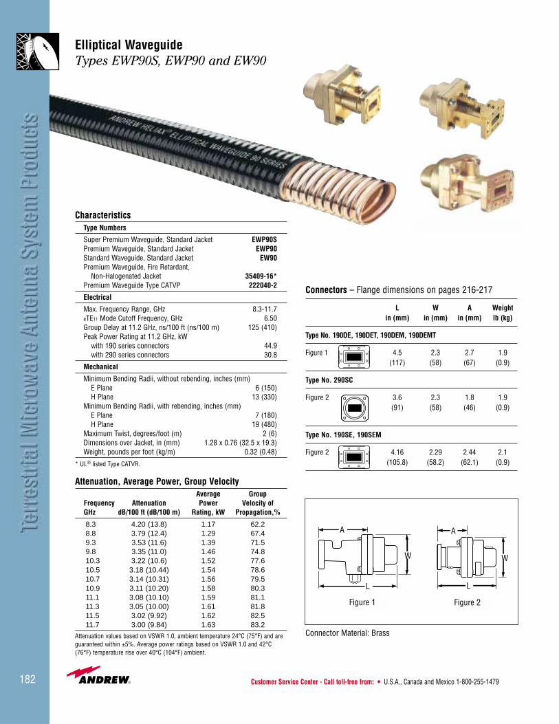
Customer Service Center - Call toll-free from: • U.S.A., Canada and Mexico 1-800-255-1479182
Elliptical WaveguideTypes EWP90S, EWP90 and EW90
Connectors – Flange dimensions on pages 216-217
L W A Weightin (mm) in (mm) in (mm) lb (kg)
Type No. 190DE, 190DET, 190DEM, 190DEMT
Figure 1 4.5 2.3 2.7 1.9(117) (58) (67) (0.9)
Type No. 290SC
Figure 2 3.6 2.3 1.8 1.9(91) (58) (46) (0.9)
Type No. 190SE, 190SEM
Figure 2 4.16 2.29 2.44 2.1(105.8) (58.2) (62.1) (0.9)
Connector Material: Brass
L
A
W W
A
L
Figure 1 Figure 2
CharacteristicsType Numbers
Super Premium Waveguide, Standard Jacket EWP90SPremium Waveguide, Standard Jacket EWP90Standard Waveguide, Standard Jacket EW90Premium Waveguide, Fire Retardant,
Non-Halogenated Jacket 35409-16*Premium Waveguide Type CATVP 222040-2
Electrical
Max. Frequency Range, GHz 8.3-11.7eTE11 Mode Cutoff Frequency, GHz 6.50Group Delay at 11.2 GHz, ns/100 ft (ns/100 m) 125 (410)Peak Power Rating at 11.2 GHz, kW
with 190 series connectors 44.9with 290 series connectors 30.8
Mechanical
Minimum Bending Radii, without rebending, inches (mm)E Plane 6 (150)H Plane 13 (330)
Minimum Bending Radii, with rebending, inches (mm)E Plane 7 (180)H Plane 19 (480)
Maximum Twist, degrees/foot (m) 2 (6)Dimensions over Jacket, in (mm) 1.28 x 0.76 (32.5 x 19.3)Weight, pounds per foot (kg/m) 0.32 (0.48)
* UL® listed Type CATVR.
Attenuation, Average Power, Group VelocityAverage Group
Frequency Attenuation Power Velocity ofGHz dB/100 ft (dB/100 m) Rating, kW Propagation,%
8.3 4.20 (13.8) 1.17 62.28.8 3.79 (12.4) 1.29 67.49.3 3.53 (11.6) 1.39 71.59.8 3.35 (11.0) 1.46 74.810.3 3.22 (10.6) 1.52 77.610.5 3.18 (10.44) 1.54 78.610.7 3.14 (10.31) 1.56 79.510.9 3.11 (10.20) 1.58 80.311.1 3.08 (10.10) 1.59 81.111.3 3.05 (10.00) 1.61 81.811.5 3.02 (9.92) 1.62 82.511.7 3.00 (9.84) 1.63 83.2
Attenuation values based on VSWR 1.0, ambient temperature 24°C (75°F) and areguaranteed within ±5%. Average power ratings based on VSWR 1.0 and 42°C(76°F) temperature rise over 40°C (104°F) ambient.
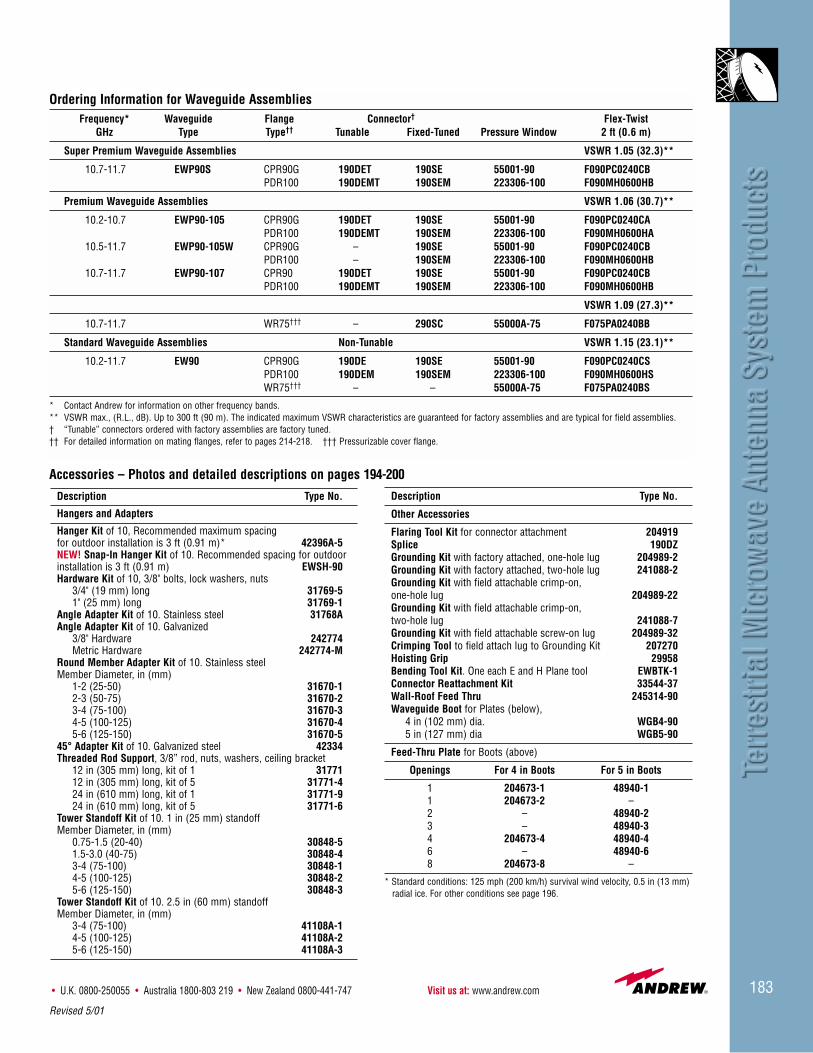
• U.K. 0800-250055 • Australia 1800-803 219 • New Zealand 0800-441-747 Visit us at: www.andrew.com 183
Ordering Information for Waveguide AssembliesFrequency* Waveguide Flange Connector† Flex-Twist
GHz Type Type†† Tunable Fixed-Tuned Pressure Window 2 ft (0.6 m)
Super Premium Waveguide Assemblies VSWR 1.05 (32.3)**
10.7-11.7 EWP90S CPR90G 190DET 190SE 55001-90 F090PC0240CBPDR100 190DEMT 190SEM 223306-100 F090MH0600HB
Premium Waveguide Assemblies VSWR 1.06 (30.7)**
10.2-10.7 EWP90-105 CPR90G 190DET 190SE 55001-90 F090PC0240CAPDR100 190DEMT 190SEM 223306-100 F090MH0600HA
10.5-11.7 EWP90-105W CPR90G – 190SE 55001-90 F090PC0240CBPDR100 – 190SEM 223306-100 F090MH0600HB
10.7-11.7 EWP90-107 CPR90 190DET 190SE 55001-90 F090PC0240CBPDR100 190DEMT 190SEM 223306-100 F090MH0600HB
VSWR 1.09 (27.3)**
10.7-11.7 WR75††† – 290SC 55000A-75 F075PA0240BB
Standard Waveguide Assemblies Non-Tunable VSWR 1.15 (23.1)**
10.2-11.7 EW90 CPR90G 190DE 190SE 55001-90 F090PC0240CSPDR100 190DEM 190SEM 223306-100 F090MH0600HSWR75††† – – 55000A-75 F075PA0240BS
* Contact Andrew for information on other frequency bands. ** VSWR max., (R.L., dB). Up to 300 ft (90 m). The indicated maximum VSWR characteristics are guaranteed for factory assemblies and are typical for field assemblies.† “Tunable” connectors ordered with factory assemblies are factory tuned. †† For detailed information on mating flanges, refer to pages 214-218. ††† Pressurizable cover flange.
Description Type No.
Hangers and Adapters
Hanger Kit of 10, Recommended maximum spacingfor outdoor installation is 3 ft (0.91 m)* 42396A-5NEW! Snap-In Hanger Kit of 10. Recommended spacing for outdoor installation is 3 ft (0.91 m) EWSH-90Hardware Kit of 10, 3/8" bolts, lock washers, nuts
3/4" (19 mm) long 31769-51" (25 mm) long 31769-1
Angle Adapter Kit of 10. Stainless steel 31768AAngle Adapter Kit of 10. Galvanized
3/8" Hardware 242774Metric Hardware 242774-M
Round Member Adapter Kit of 10. Stainless steelMember Diameter, in (mm)
1-2 (25-50) 31670-12-3 (50-75) 31670-23-4 (75-100) 31670-34-5 (100-125) 31670-45-6 (125-150) 31670-5
45° Adapter Kit of 10. Galvanized steel 42334Threaded Rod Support, 3/8” rod, nuts, washers, ceiling bracket
12 in (305 mm) long, kit of 1 3177112 in (305 mm) long, kit of 5 31771-424 in (610 mm) long, kit of 1 31771-924 in (610 mm) long, kit of 5 31771-6
Tower Standoff Kit of 10. 1 in (25 mm) standoffMember Diameter, in (mm)
0.75-1.5 (20-40) 30848-51.5-3.0 (40-75) 30848-43-4 (75-100) 30848-14-5 (100-125) 30848-25-6 (125-150) 30848-3
Tower Standoff Kit of 10. 2.5 in (60 mm) standoffMember Diameter, in (mm)
3-4 (75-100) 41108A-14-5 (100-125) 41108A-25-6 (125-150) 41108A-3
Description Type No.
Other Accessories
Flaring Tool Kit for connector attachment 204919Splice 190DZGrounding Kit with factory attached, one-hole lug 204989-2Grounding Kit with factory attached, two-hole lug 241088-2Grounding Kit with field attachable crimp-on, one-hole lug 204989-22Grounding Kit with field attachable crimp-on, two-hole lug 241088-7Grounding Kit with field attachable screw-on lug 204989-32Crimping Tool to field attach lug to Grounding Kit 207270Hoisting Grip 29958Bending Tool Kit. One each E and H Plane tool EWBTK-1Connector Reattachment Kit 33544-37Wall-Roof Feed Thru 245314-90Waveguide Boot for Plates (below),
4 in (102 mm) dia. WGB4-905 in (127 mm) dia WGB5-90
Feed-Thru Plate for Boots (above)
Openings For 4 in Boots For 5 in Boots
1 204673-1 48940-11 204673-2 –2 – 48940-23 – 48940-34 204673-4 48940-46 – 48940-68 204673-8 –
* Standard conditions: 125 mph (200 km/h) survival wind velocity, 0.5 in (13 mm) radial ice. For other conditions see page 196.
Accessories – Photos and detailed descriptions on pages 194-200
Revised 5/01
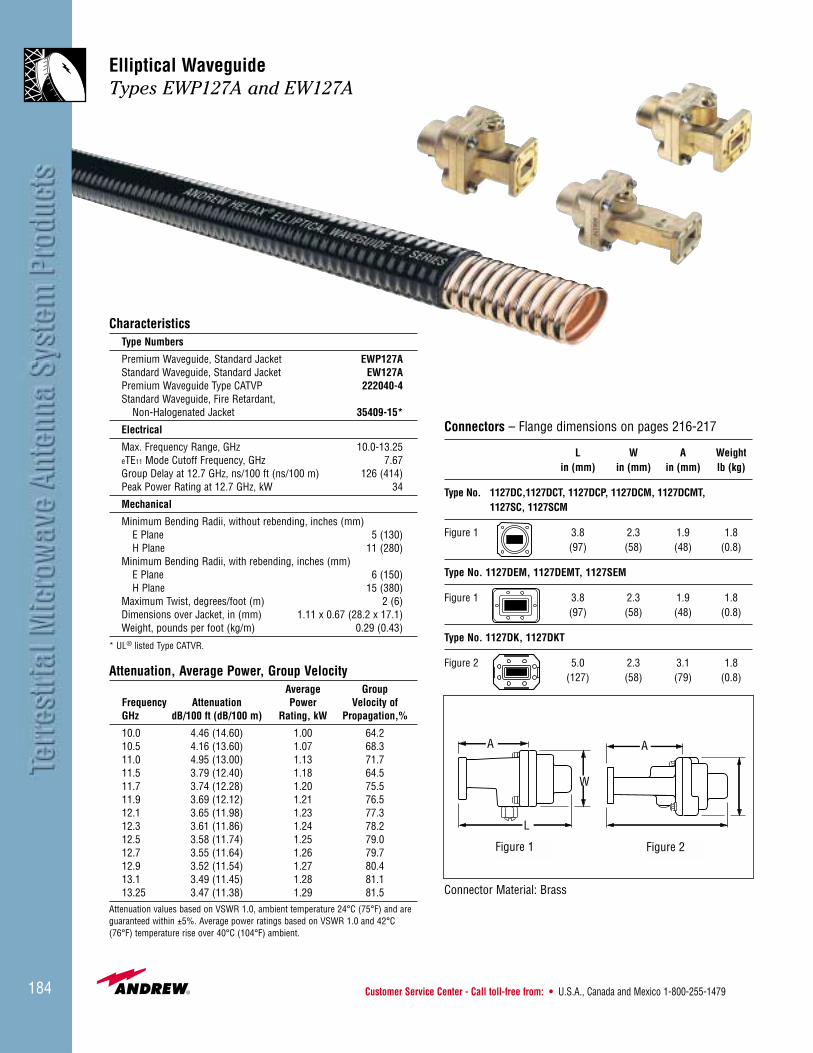
Customer Service Center - Call toll-free from: • U.S.A., Canada and Mexico 1-800-255-1479184
Elliptical WaveguideTypes EWP127A and EW127A
CharacteristicsType Numbers
Premium Waveguide, Standard Jacket EWP127AStandard Waveguide, Standard Jacket EW127APremium Waveguide Type CATVP 222040-4Standard Waveguide, Fire Retardant,
Non-Halogenated Jacket 35409-15*
Electrical
Max. Frequency Range, GHz 10.0-13.25eTE11 Mode Cutoff Frequency, GHz 7.67Group Delay at 12.7 GHz, ns/100 ft (ns/100 m) 126 (414)Peak Power Rating at 12.7 GHz, kW 34
Mechanical
Minimum Bending Radii, without rebending, inches (mm)E Plane 5 (130)H Plane 11 (280)
Minimum Bending Radii, with rebending, inches (mm)E Plane 6 (150)H Plane 15 (380)
Maximum Twist, degrees/foot (m) 2 (6)Dimensions over Jacket, in (mm) 1.11 x 0.67 (28.2 x 17.1)Weight, pounds per foot (kg/m) 0.29 (0.43)
* UL® listed Type CATVR.
Attenuation, Average Power, Group VelocityAverage Group
Frequency Attenuation Power Velocity ofGHz dB/100 ft (dB/100 m) Rating, kW Propagation,%
10.0 4.46 (14.60) 1.00 64.210.5 4.16 (13.60) 1.07 68.311.0 4.95 (13.00) 1.13 71.711.5 3.79 (12.40) 1.18 64.511.7 3.74 (12.28) 1.20 75.511.9 3.69 (12.12) 1.21 76.512.1 3.65 (11.98) 1.23 77.312.3 3.61 (11.86) 1.24 78.212.5 3.58 (11.74) 1.25 79.012.7 3.55 (11.64) 1.26 79.712.9 3.52 (11.54) 1.27 80.413.1 3.49 (11.45) 1.28 81.113.25 3.47 (11.38) 1.29 81.5
Attenuation values based on VSWR 1.0, ambient temperature 24°C (75°F) and areguaranteed within ±5%. Average power ratings based on VSWR 1.0 and 42°C(76°F) temperature rise over 40°C (104°F) ambient.
Connector Material: Brass
L
A
W
A
Figure 1 Figure 2
Connectors – Flange dimensions on pages 216-217
L W A Weightin (mm) in (mm) in (mm) lb (kg)
Type No. 1127DC,1127DCT, 1127DCP, 1127DCM, 1127DCMT, 1127SC, 1127SCM
Figure 1 3.8 2.3 1.9 1.8(97) (58) (48) (0.8)
Type No. 1127DEM, 1127DEMT, 1127SEM
Figure 1 3.8 2.3 1.9 1.8(97) (58) (48) (0.8)
Type No. 1127DK, 1127DKT
Figure 2 5.0 2.3 3.1 1.8(127) (58) (79) (0.8)
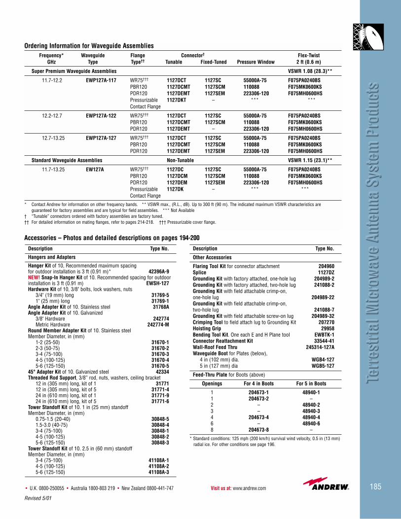
• U.K. 0800-250055 • Australia 1800-803 219 • New Zealand 0800-441-747 Visit us at: www.andrew.com 185
Ordering Information for Waveguide AssembliesFrequency* Waveguide Flange Connector† Flex-Twist
GHz Type Type†† Tunable Fixed-Tuned Pressure Window 2 ft (0.6 m)
Super Premium Waveguide Assemblies VSWR 1.08 (28.3)**
11.7-12.2 EWP127A-117 WR75††† 1127DCT 1127SC 55000A-75 F075PA0240BSPBR120 1127DCMT 1127SCM 110088 F075MK0600KSPDR120 1127DEMT 1127SEM 223306-120 F075MH0600HSPressurizable 1127DKT – *** ***Contact Flange
12.2-12.7 EWP127A-122 WR75††† 1127DCT 1127SC 55000A-75 F075PA0240BSPBR120 1127DCMT 1127SCM 110088 F075MK0600KSPDR120 1127DEMT – 223306-120 F075MH0600HS
12.7-13.25 EWP127A-127 WR75††† 1127DCT 1127SC 55000A-75 F075PA0240BSPBR120 1127DCMT 1127SCM 110088 F075MK0600KSPDR120 1127DEMT 1127SEM 223306-120 F075MH0600HS
Standard Waveguide Assemblies Non-Tunable VSWR 1.15 (23.1)**
11.7-13.25 EW127A WR75††† 1127DC 1127SC 55000A-75 F075PA0240BSPBR120 1127DCM 1127SCM 110088 F075MK0600KSPDR120 1127DEM 1127SEM 223306-120 F075MH0600HSPressurizable 1127DK – *** ***Contact Flange
* Contact Andrew for information on other frequency bands. ** VSWR max., (R.L., dB). Up to 300 ft (90 m). The indicated maximum VSWR characteristics are guaranteed for factory assemblies and are typical for field assemblies. *** Not Available
† “Tunable” connectors ordered with factory assemblies are factory tuned. †† For detailed information on mating flanges, refer to pages 214-218. ††† Pressurizable cover flange.
Description Type No.
Hangers and Adapters
Hanger Kit of 10, Recommended maximum spacingfor outdoor installation is 3 ft (0.91 m)* 42396A-9NEW! Snap-In Hanger Kit of 10. Recommended spacing for outdoor installation is 3 ft (0.91 m) EWSH-127Hardware Kit of 10, 3/8" bolts, lock washers, nuts
3/4" (19 mm) long 31769-51" (25 mm) long 31769-1
Angle Adapter Kit of 10. Stainless steel 31768AAngle Adapter Kit of 10. Galvanized
3/8" Hardware 242774Metric Hardware 242774-M
Round Member Adapter Kit of 10. Stainless steelMember Diameter, in (mm)
1-2 (25-50) 31670-12-3 (50-75) 31670-23-4 (75-100) 31670-34-5 (100-125) 31670-45-6 (125-150) 31670-5
45° Adapter Kit of 10. Galvanized steel 42334Threaded Rod Support, 3/8” rod, nuts, washers, ceiling bracket
12 in (305 mm) long, kit of 1 3177112 in (305 mm) long, kit of 5 31771-424 in (610 mm) long, kit of 1 31771-924 in (610 mm) long, kit of 5 31771-6
Tower Standoff Kit of 10. 1 in (25 mm) standoffMember Diameter, in (mm)
0.75-1.5 (20-40) 30848-51.5-3.0 (40-75) 30848-43-4 (75-100) 30848-14-5 (100-125) 30848-25-6 (125-150) 30848-3
Tower Standoff Kit of 10. 2.5 in (60 mm) standoffMember Diameter, in (mm)
3-4 (75-100) 41108A-14-5 (100-125) 41108A-25-6 (125-150) 41108A-3
Description Type No.
Other Accessories
Flaring Tool Kit for connector attachment 204960Splice 1127DZGrounding Kit with factory attached, one-hole lug 204989-2Grounding Kit with factory attached, two-hole lug 241088-2Grounding Kit with field attachable crimp-on, one-hole lug 204989-22Grounding Kit with field attachable crimp-on, two-hole lug 241088-7Grounding Kit with field attachable screw-on lug 204989-32Crimping Tool to field attach lug to Grounding Kit 207270Hoisting Grip 29958Bending Tool Kit. One each E and H Plane tool EWBTK-1Connector Reattachment Kit 33544-41Wall-Roof Feed Thru 245314-127AWaveguide Boot for Plates (below),
4 in (102 mm) dia. WGB4-1275 in (127 mm) dia WGB5-127
Feed-Thru Plate for Boots (above)
Openings For 4 in Boots For 5 in Boots
1 204673-1 48940-11 204673-2 –2 – 48940-23 – 48940-34 204673-4 48940-46 – 48940-68 204673-8 –
* Standard conditions: 125 mph (200 km/h) survival wind velocity, 0.5 in (13 mm) radial ice. For other conditions see page 196.
Accessories – Photos and detailed descriptions on pages 194-200
Revised 5/01
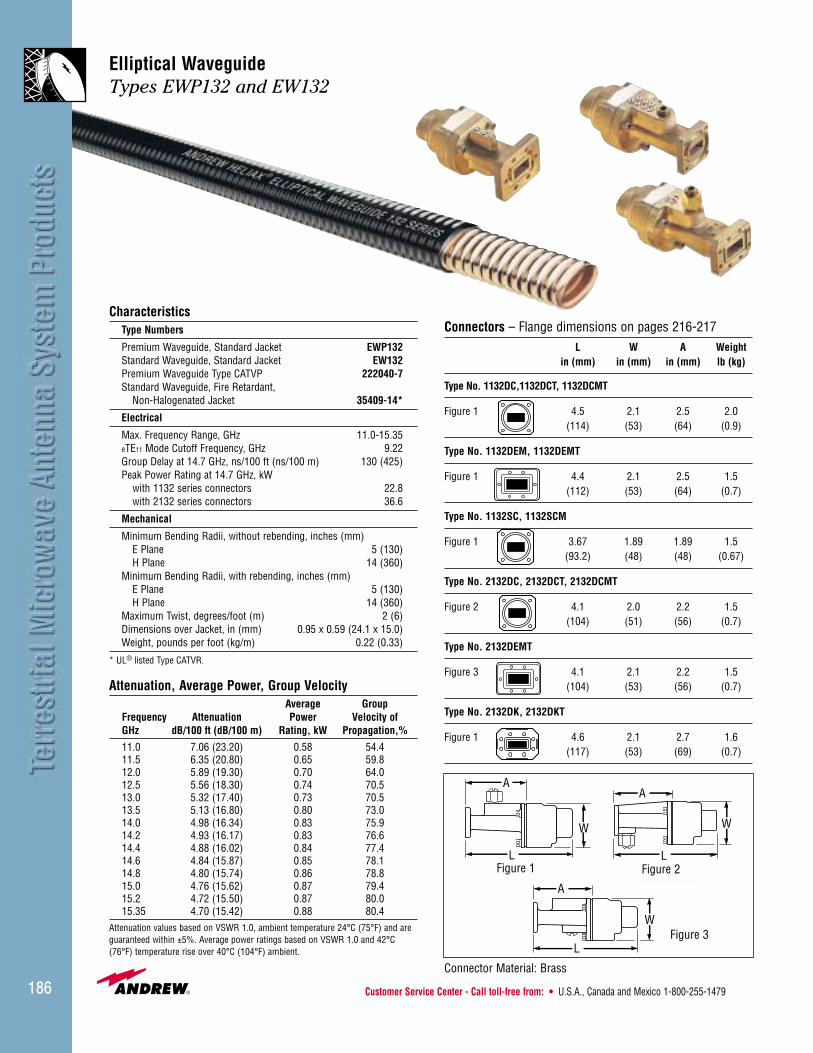
Customer Service Center - Call toll-free from: • U.S.A., Canada and Mexico 1-800-255-1479186
Connectors – Flange dimensions on pages 216-217L W A Weight
in (mm) in (mm) in (mm) lb (kg)
Type No. 1132DC,1132DCT, 1132DCMT
Figure 1 4.5 2.1 2.5 2.0(114) (53) (64) (0.9)
Type No. 1132DEM, 1132DEMT
Figure 1 4.4 2.1 2.5 1.5(112) (53) (64) (0.7)
Type No. 1132SC, 1132SCM
Figure 1 3.67 1.89 1.89 1.5(93.2) (48) (48) (0.67)
Type No. 2132DC, 2132DCT, 2132DCMT
Figure 2 4.1 2.0 2.2 1.5(104) (51) (56) (0.7)
Type No. 2132DEMT
Figure 3 4.1 2.1 2.2 1.5(104) (53) (56) (0.7)
Type No. 2132DK, 2132DKT
Figure 1 4.6 2.1 2.7 1.6(117) (53) (69) (0.7)
Elliptical WaveguideTypes EWP132 and EW132
Connector Material: Brass
L
A
WW
A
LFigure 1 Figure 2
A
W
LFigure 3
CharacteristicsType Numbers
Premium Waveguide, Standard Jacket EWP132Standard Waveguide, Standard Jacket EW132Premium Waveguide Type CATVP 222040-7Standard Waveguide, Fire Retardant,
Non-Halogenated Jacket 35409-14*
Electrical
Max. Frequency Range, GHz 11.0-15.35eTE11 Mode Cutoff Frequency, GHz 9.22Group Delay at 14.7 GHz, ns/100 ft (ns/100 m) 130 (425)Peak Power Rating at 14.7 GHz, kW
with 1132 series connectors 22.8with 2132 series connectors 36.6
Mechanical
Minimum Bending Radii, without rebending, inches (mm)E Plane 5 (130)H Plane 14 (360)
Minimum Bending Radii, with rebending, inches (mm)E Plane 5 (130)H Plane 14 (360)
Maximum Twist, degrees/foot (m) 2 (6)Dimensions over Jacket, in (mm) 0.95 x 0.59 (24.1 x 15.0)Weight, pounds per foot (kg/m) 0.22 (0.33)
* UL® listed Type CATVR.
Attenuation, Average Power, Group VelocityAverage Group
Frequency Attenuation Power Velocity ofGHz dB/100 ft (dB/100 m) Rating, kW Propagation,%
11.0 7.06 (23.20) 0.58 54.411.5 6.35 (20.80) 0.65 59.812.0 5.89 (19.30) 0.70 64.012.5 5.56 (18.30) 0.74 70.513.0 5.32 (17.40) 0.73 70.513.5 5.13 (16.80) 0.80 73.014.0 4.98 (16.34) 0.83 75.914.2 4.93 (16.17) 0.83 76.614.4 4.88 (16.02) 0.84 77.414.6 4.84 (15.87) 0.85 78.114.8 4.80 (15.74) 0.86 78.815.0 4.76 (15.62) 0.87 79.415.2 4.72 (15.50) 0.87 80.015.35 4.70 (15.42) 0.88 80.4
Attenuation values based on VSWR 1.0, ambient temperature 24°C (75°F) and areguaranteed within ±5%. Average power ratings based on VSWR 1.0 and 42°C(76°F) temperature rise over 40°C (104°F) ambient.
186
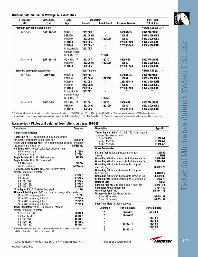
• U.K. 0800-250055 • Australia 1800-803 219 • New Zealand 0800-441-747 Visit us at: www.andrew.com 187
Description Type No.
Hangers and Adapters
Hanger Kit of 10, Recommended maximum spacingfor outdoor installation is 3 ft (0.91 m)* 42396A-9NEW! Snap-In Hanger Kit of 10. Recommended spacing for outdoor installation is 3 ft (0.91 m) EWSH-132Hardware Kit of 10, 3/8" bolts, lock washers, nuts
3/4" (19 mm) long 31769-51" (25 mm) long 31769-1
Angle Adapter Kit of 10. Stainless steel 31768AAngle Adapter Kit of 10. Galvanized
3/8" Hardware 242774Metric Hardware 242774-M
Round Member Adapter Kit of 10. Stainless steelMember Diameter, in (mm)
1-2 (25-50) 31670-12-3 (50-75) 31670-23-4 (75-100) 31670-34-5 (100-125) 31670-45-6 (125-150) 31670-5
45° Adapter Kit of 10. Galvanized steel 42334Threaded Rod Support, 3/8” rod, nuts, washers, ceiling bracket
12 in (305 mm) long, kit of 1 3177112 in (305 mm) long, kit of 5 31771-424 in (610 mm) long, kit of 1 31771-924 in (610 mm) long, kit of 5 31771-6
Tower Standoff Kit of 10. 1 in (25 mm) standoffMember Diameter, in (mm)
0.75-1.5 (20-40) 30848-51.5-3.0 (40-75) 30848-43-4 (75-100) 30848-14-5 (100-125) 30848-25-6 (125-150) 30848-3
* Standard conditions: 125 mph (200 km/h) survival wind velocity, 0.5 in (13 mm) radial ice. For other conditions see page 196.
Description Type No.
Tower Standoff Kit of 10. 2.5 in (60 mm) standoffMember Diameter, in (mm)
3-4 (75-100) 41108A-14-5 (100-125) 41108A-25-6 (125-150) 41108A-3
Other Accessories
Flaring Tool Kit for connector attachment 203809Splice 1132DZGrounding Kit with factory attached, one-hole lug 204989-2Grounding Kit with factory attached, two-hole lug 241088-2Grounding Kit with field attachable crimp-on, one-hole lug 204989-22Grounding Kit with field attachable crimp-on, two-hole lug 241088-7Grounding Kit with field attachable screw-on lug 204989-32Crimping Tool to field attach lug to Grounding Kit 207270Hoisting Grip 29958Bending Tool Kit. One each E and H Plane tool EWBTK-1Connector Reattachment Kit 33544-39Wall-Roof Feed Thru 245314-132Waveguide Boot for Plates (below),
4 in (102 mm) dia. WGB4-1325 in (127 mm) dia WGB5-132
Feed-Thru Plate for Boots (above)
Openings For 4 in Boots For 5 in Boots
1 204673-1 48940-11 204673-2 –2 – 48940-23 – 48940-34 204673-4 48940-46 – 48940-68 204673-8 –
Accessories – Photos and detailed descriptions on pages 194-200
Ordering Information for Waveguide AssembliesFrequency* Waveguide Flange Connector† Flex-Twist
GHz Type Type†† Tunable Fixed-Tuned Pressure Window 2 ft (0.6 m)
Premium Waveguide Assemblies VSWR 1.08 (28.3)**
14.0-14.5 EWP132-140 WR75††† 2132DCT – 55000A-75 F075PA0240BSPBR120 2132DCMT – 110088 F075MK0600KSPBR140 1132DCMT 1132SCM 110089 F062MK0600KSPDR120 2132DEMT – 223306-120 F075MH0600HSPDR140 1132DEMT – 223306-140 F062MH0600HSPressurizable 2132DKT – *** ***Contact FlangeUG-541/U†††† 1132SC
14.4-15.35 EWP132-144 UG-541/U†††† 1132DCT 1132SC 55000-62 F062PA0240BSPBR140 1132DCMT 1132SCM 110089 F062MK0600KSPDR140 1132DEMT – 223306-140 F062MH0600HS
Standard Waveguide Assemblies Non-Tunable VSWR 1.15 (23.1)**
14.0-14.5 EW132-140 WR75††† 2132DC – 55000A-75 F075PA0240BSPBR140 1132DCM 1132SCM 110089 F062MK0600KSPDR140 1132DEM – 223306-140 F062MH0600HSPBR120 2132DCM – 110088 F075MK0600KSPDR120 2132DEM – 223306-120 F075MH0600HSPressurizable 2132DK – *** ***Contact FlangeUG-541/U†††† 1132SC
14.4-15.35 EW132-144 UG-541/U†††† 1132DC 1132SC 55000-62 F062PA0240BSPBR140 1132DCM 1132SCM 110089 F062MK0600KSPDR140 1132DEM – 223306-140 F062MH0600HS
* Contact Andrew for information on other frequency bands. **VSWR max., (R.L., dB). Up to 300 ft (90 m). The indicated maximum VSWR characteristics are guaranteed for factory assemblies and are typical for field assemblies. *** Not Available † “Tunable” connectors ordered with factory assemblies are factory
Revised 7/00 & 5/01
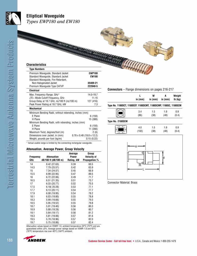
Customer Service Center - Call toll-free from: • U.S.A., Canada and Mexico 1-800-255-1479188
Connectors – Flange dimensions on pages 216-217
L W A Weightin (mm) in (mm) in (mm) lb (kg)
Type No. 1180DCT, 1180DCP, 1180DCMT, 1180DCMP, 1180SC, 1180SCM
3.4 1.5 1.9 0.9(86) (38) (48) (0.4)
Type No. 2180SEM
4.0 1.5 1.9 0.9(102) (38) (48) (0.4)
Elliptical WaveguideTypes EWP180 and EW180
Connector Material: Brass
W
A
L
CharacteristicsType Numbers
Premium Waveguide, Standard Jacket EWP180Standard Waveguide, Standard Jacket EW180Standard Waveguide, Fire Retardant,
Non-Halogenated Jacket 35409-21Premium Waveguide Type CATVP 222040-5
Electrical
Max. Frequency Range, GHz* 14.0-19.7eTE11 Mode Cutoff Frequency, GHz 11.15Group Delay at 18.7 GHz, ns/100 ft (ns/100 m) 127 (416)Peak Power Rating at 18.7 GHz, kW 7.3
Mechanical
Minimum Bending Radii, without rebending, inches (mm)E Plane 6 (150)H Plane 15 (380)
Minimum Bending Radii, with rebending, inches (mm)E Plane 6 (150)H Plane 11 (280)
Maximum Twist, degrees/foot (m) 2 (6)Dimensions over Jacket, in (mm) 0.78 x 0.48 (19.8 x 12.2)Weight, pounds per foot (kg/m) 0.15 (0.22)
* Actual usable range is limited by the connecting rectangular waveguide.
Attenuation, Average Power, Group VelocityAverage Group
Frequency Attenuation Power Velocity ofGHz dB/100 ft (dB/100 m) Rating, kW Propagation,%
14 8.42 (27.63) 0.39 60.514.5 7.79 (25.57) 0.42 63.915 7.34 (24.07) 0.45 66.915.5 6.99 (22.95) 0.47 89.516 6.72 (22.06) 0.49 71.716.5 6.51 (21.35) 0.51 73.717 6.33 (20.77) 0.52 75.517.5 6.18( 20.28) 0.53 77.117.7 6.13 (20.11) 0.54 77.717.9 6.08 (19.95) 0.54 78.218.1 6.03 (19.80) 0.55 78.818.3 5.99 (19.66) 0.55 79.318.5 5.95 (19.52) 0.55 79.818.7 5.91 (19.40) 0.56 80.318.9 5.88 (19.28) 0.56 80.719.1 5.84 (19.17) 0.56 81.219.3 5.81 (19.06) 0.57 81.619.5 5.78 (18.96) 0.57 82.019.7 5.75 (18.86) 0.57 82.4
Attenuation values based on VSWR 1.0, ambient temperature 24°C (75°F) and areguaranteed within ±5%. Average power ratings based on VSWR 1.0 and 42°C(76°F) temperature rise over 40°C (104°F) ambient.
• U.K. 0800-250055 • Australia 1800-803 219 • New Zealand 0800-441-747 Visit us at: www.andrew.com 189
Ordering Information for Waveguide AssembliesFrequency* Waveguide Flange Connector† Flex-Twist
GHz Type Type†† Tunable Fixed-Tuned Pressure Window 2 ft (0.6 m)
Premium Waveguide Assemblies VSWR 1.08 (28.3)**
17.7-19.7 EWP180-180 UG-595/U††† 1180DCT 1180SC 55000A-42 F042PA0240BSPBR220 1180DCMT 118SCM 112587 F042MK0600KSPDR180 – 2180SEM 223306-180 F051MH0600HS
Standard Waveguide Assemblies VSWR 1.15 (23.1)**
17.7-19.7 EW180 UG-595/U††† 1180DCT 1180SC 55000A-42 F042PA0240BSPBR220 1180DCMT 1180SCM 112587 F042MK0600KSPDR180 – 2180SEM 223306-180 F051MH0600HS
* Contact Andrew for information on other frequency bands. ** VSWR max., (R.L., dB). Up to 300 ft (90 m). The indicated maximum VSWR characteristics are guaranteed for factory assemblies and are typical for field assemblies.† “Tunable” connectors ordered with factory assemblies are factory tuned. †† For detailed information on mating flanges, refer to pages 214-218.††† Modified cover flange with gasket groove. Mates with UG choke or cover flanges.
Description Type No.
Hangers and Adapters
Hanger Kit of 10, Recommended maximum spacingfor outdoor installation is 3 ft (0.91 m)* 43211ANEW! Snap-In Hanger Kit of 10. Recommended spacing for outdoor installation is 3 ft (0.91 m) EWSH-180Hardware Kit of 10, 3/8" bolts, lock washers, nuts
3/4" (19 mm) long 31769-51" (25 mm) long 31769-1
Angle Adapter Kit of 10. Stainless steel 31768AAngle Adapter Kit of 10. Galvanized
3/8" Hardware 242774Metric Hardware 242774-M
Round Member Adapter Kit of 10. Stainless steelMember Diameter, in (mm)
1-2 (25-50) 31670-12-3 (50-75) 31670-23-4 (75-100) 31670-34-5 (100-125) 31670-45-6 (125-150) 31670-5
45° Adapter Kit of 10. Galvanized steel 42334Threaded Rod Support, 3/8” rod, nuts, washers, ceiling bracket
12 in (305 mm) long, kit of 1 3177112 in (305 mm) long, kit of 5 31771-424 in (610 mm) long, kit of 1 31771-924 in (610 mm) long, kit of 5 31771-6
Tower Standoff Kit of 10. 1 in (25 mm) standoffMember Diameter, in (mm)
0.75-1.5 (20-40) 30848-51.5-3.0 (40-75) 30848-43-4 (75-100) 30848-14-5 (100-125) 30848-25-6 (125-150) 30848-3
Tower Standoff Kit of 10. 2.5 in (60 mm) standoffMember Diameter, in (mm)
3-4 (75-100) 41108A-14-5 (100-125) 41108A-25-6 (125-150) 41108A-3
Description Type No.
Other Accessories
Flaring Tool Kit for connector attachment 201439Splice 1180DZGrounding Kit with factory attached, one-hole lug 204989-1Grounding Kit with factory attached, two-hole lug 241088-1Grounding Kit with field attachable crimp-on, one-hole lug 204989-21Grounding Kit with field attachable crimp-on, two-hole lug 241088-6Grounding Kit with field attachable screw-on lug 204989-31Crimping Tool to field attach lug to Grounding Kit 207270Hoisting Grip 43094Bending Tool Kit. One each E and H Plane tool EWBTK-1Connector Reattachment Kit 33544-42Wall-Roof Feed Thru 245314-180Waveguide Boot for Plates (below),
4 in (102 mm) dia. WGB4-1805 in (127 mm) dia WGB5-180
Feed-Thru Plate for Boots (above)
Openings For 4 in Boots For 5 in Boots
1 204673-1 48940-11 204673-2 –2 – 48940-23 – 48940-34 204673-4 48940-46 – 48940-68 204673-8 –
* Standard conditions: 125 mph (200 km/h) survival wind velocity, 0.5 in (13 mm) radial ice. For other conditions see page 196.
Accessories – Photos and detailed descriptions on pages 194-200
Revised 7/00 & 5/01
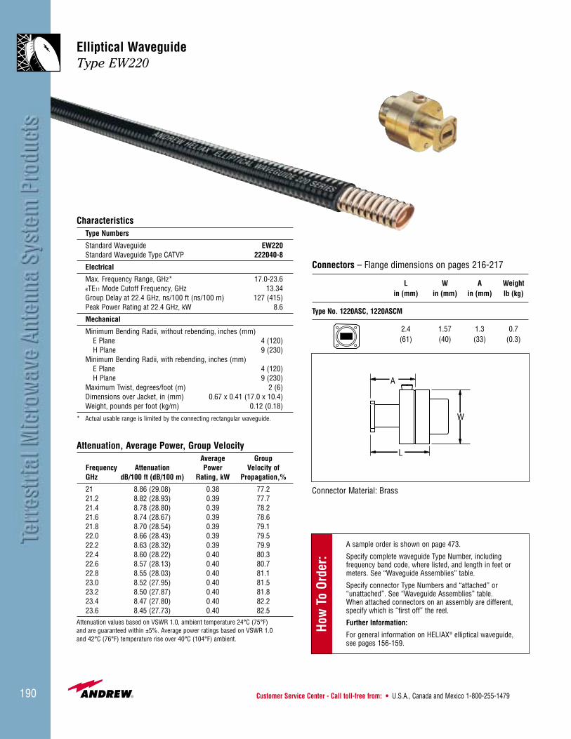
Customer Service Center - Call toll-free from: • U.S.A., Canada and Mexico 1-800-255-1479190
Connectors – Flange dimensions on pages 216-217
L W A Weightin (mm) in (mm) in (mm) lb (kg)
Type No. 1220ASC, 1220ASCM
2.4 1.57 1.3 0.7(61) (40) (33) (0.3)
Connector Material: Brass
Elliptical WaveguideType EW220
CharacteristicsType Numbers
Standard Waveguide EW220Standard Waveguide Type CATVP 222040-8
Electrical
Max. Frequency Range, GHz* 17.0-23.6eTE11 Mode Cutoff Frequency, GHz 13.34Group Delay at 22.4 GHz, ns/100 ft (ns/100 m) 127 (415)Peak Power Rating at 22.4 GHz, kW 8.6
Mechanical
Minimum Bending Radii, without rebending, inches (mm)E Plane 4 (120)H Plane 9 (230)
Minimum Bending Radii, with rebending, inches (mm)E Plane 4 (120)H Plane 9 (230)
Maximum Twist, degrees/foot (m) 2 (6)Dimensions over Jacket, in (mm) 0.67 x 0.41 (17.0 x 10.4)Weight, pounds per foot (kg/m) 0.12 (0.18)
* Actual usable range is limited by the connecting rectangular waveguide.
Attenuation, Average Power, Group VelocityAverage Group
Frequency Attenuation Power Velocity ofGHz dB/100 ft (dB/100 m) Rating, kW Propagation,%
21 8.86 (29.08) 0.38 77.221.2 8.82 (28.93) 0.39 77.721.4 8.78 (28.80) 0.39 78.221.6 8.74 (28.67) 0.39 78.621.8 8.70 (28.54) 0.39 79.122.0 8.66 (28.43) 0.39 79.522.2 8.63 (28.32) 0.39 79.922.4 8.60 (28.22) 0.40 80.322.6 8.57 (28.13) 0.40 80.722.8 8.55 (28.03) 0.40 81.123.0 8.52 (27.95) 0.40 81.523.2 8.50 (27.87) 0.40 81.823.4 8.47 (27.80) 0.40 82.223.6 8.45 (27.73) 0.40 82.5
Attenuation values based on VSWR 1.0, ambient temperature 24°C (75°F) and are guaranteed within ±5%. Average power ratings based on VSWR 1.0 and 42°C (76°F) temperature rise over 40°C (104°F) ambient.
L
A
W
How
To
Orde
r:
A sample order is shown on page 473.
Specify complete waveguide Type Number, including frequency band code, where listed, and length in feet ormeters. See “Waveguide Assemblies” table.
Specify connector Type Numbers and “attached” or“unattached”. See “Waveguide Assemblies” table. When attached connectors on an assembly are different,specify which is “first off” the reel.
Further Information:
For general information on HELIAX® elliptical waveguide,see pages 156-159.
• U.K. 0800-250055 • Australia 1800-803 219 • New Zealand 0800-441-747 Visit us at: www.andrew.com 191
Ordering Information for Waveguide AssembliesFrequency* Waveguide Flange Connector Flex-Twist
GHz Type Type†† Fixed-Tuned Pressure Window 2 ft (0.6 m)
Premium Waveguide Assemblies VSWR 1.15 (23.1)**
21.2-23.6 EW220 UG-595/U††† 1220ASC 55000A-42 F042PA0240BSPBR220 1220ASCM 112587 F042MK0600KS
* Contact Andrew for information on other frequency bands. ** VSWR max., (R.L., dB). Up to 300 ft (90 m). The indicated maximum VSWR characteristics are guaranteed for factory assemblies and are typical for field assemblies.†† For detailed information on mating flanges, refer to pages 214-218.†††Modified cover flange with gasket groove. Mates with UG choke or cover flanges.
Description Type No.
Hangers and Adapters
Hanger Kit of 10, Recommended maximum spacingfor outdoor installation is 3 ft (0.91 m)* 43211ANEW! Snap-In Hanger Kit of 10. Recommended spacing for outdoor installation is 3 ft (0.91 m) EWSH-220Hardware Kit of 10, 3/8" bolts, lock washers, nuts
3/4" (19 mm) long 31769-51" (25 mm) long 31769-1
Angle Adapter Kit of 10. Stainless steel 31768AAngle Adapter Kit of 10. Galvanized
3/8" Hardware 242774Metric Hardware 242774-M
Round Member Adapter Kit of 10. Stainless steelMember Diameter, in (mm)
1-2 (25-50) 31670-12-3 (50-75) 31670-23-4 (75-100) 31670-34-5 (100-125) 31670-45-6 (125-150) 31670-5
45° Adapter Kit of 10. Galvanized steel 42334Threaded Rod Support, 3/8” rod, nuts, washers, ceiling bracket
12 in (305 mm) long, kit of 1 3177112 in (305 mm) long, kit of 5 31771-424 in (610 mm) long, kit of 1 31771-924 in (610 mm) long, kit of 5 31771-6
Tower Standoff Kit of 10. 1 in (25 mm) standoffMember Diameter, in (mm)
0.75-1.5 (20-40) 30848-51.5-3.0 (40-75) 30848-43-4 (75-100) 30848-14-5 (100-125) 30848-25-6 (125-150) 30848-3
Tower Standoff Kit of 10. 2.5 in (60 mm) standoffMember Diameter, in (mm)
3-4 (75-100) 41108A-14-5 (100-125) 41108A-25-6 (125-150) 41108A-3
* Standard conditions: 125 mph (200 km/h) survival wind velocity, 0.5 in (13 mm) radial ice. For other conditions see page 196.
Description Type No.
Other Accessories
Flaring Tool Kit for connector attachment 205127Splice 1220DZGrounding Kit with factory attached, one-hole lug 204989-1Grounding Kit with factory attached, two-hole lug 241088-1Grounding Kit with field attachable crimp-on, one-hole lug 204989-21Grounding Kit with field attachable crimp-on, two-hole lug 241088-6Grounding Kit with field attachable screw-on lug 204989-31Crimping Tool to field attach lug to Grounding Kit 207270Hoisting Grip 43094Bending Tool Kit. One each E and H Plane tool EWBTK-1Connector Reattachment Kit 33544-44AWall-Roof Feed Thru 245314-220Waveguide Boot for Plates (below),
4 in (102 mm) dia. WGB4-2205 in (127 mm) dia WGB5-220
Feed-Thru Plate for Boots (above)
Openings For 4 in Boots For 5 in Boots
1 204673-1 48940-11 204673-2 –2 – 48940-23 – 48940-34 204673-4 48940-46 – 48940-68 204673-8 –
Accessories – Photos and detailed descriptions on pages 194-200
Revised 5/01
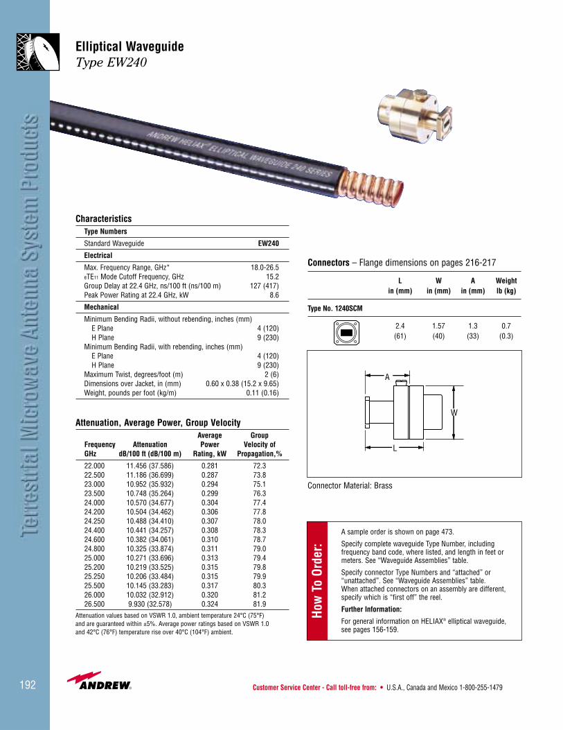
Customer Service Center - Call toll-free from: • U.S.A., Canada and Mexico 1-800-255-1479192
Connectors – Flange dimensions on pages 216-217
L W A Weightin (mm) in (mm) in (mm) lb (kg)
Type No. 1240SCM
2.4 1.57 1.3 0.7(61) (40) (33) (0.3)
Connector Material: Brass
Elliptical WaveguideType EW240
CharacteristicsType Numbers
Standard Waveguide EW240
Electrical
Max. Frequency Range, GHz* 18.0-26.5eTE11 Mode Cutoff Frequency, GHz 15.2Group Delay at 22.4 GHz, ns/100 ft (ns/100 m) 127 (417)Peak Power Rating at 22.4 GHz, kW 8.6
Mechanical
Minimum Bending Radii, without rebending, inches (mm)E Plane 4 (120)H Plane 9 (230)
Minimum Bending Radii, with rebending, inches (mm)E Plane 4 (120)H Plane 9 (230)
Maximum Twist, degrees/foot (m) 2 (6)Dimensions over Jacket, in (mm) 0.60 x 0.38 (15.2 x 9.65)Weight, pounds per foot (kg/m) 0.11 (0.16)
Attenuation, Average Power, Group VelocityAverage Group
Frequency Attenuation Power Velocity ofGHz dB/100 ft (dB/100 m) Rating, kW Propagation,%
22.000 11.456 (37.586) 0.281 72.322.500 11.186 (36.699) 0.287 73.823.000 10.952 (35.932) 0.294 75.123.500 10.748 (35.264) 0.299 76.324.000 10.570 (34.677) 0.304 77.424.200 10.504 (34.462) 0.306 77.824.250 10.488 (34.410) 0.307 78.024.400 10.441 (34.257) 0.308 78.324.600 10.382 (34.061) 0.310 78.724.800 10.325 (33.874) 0.311 79.025.000 10.271 (33.696) 0.313 79.425.200 10.219 (33.525) 0.315 79.825.250 10.206 (33.484) 0.315 79.925.500 10.145 (33.283) 0.317 80.326.000 10.032 (32.912) 0.320 81.226.500 9.930 (32.578) 0.324 81.9
Attenuation values based on VSWR 1.0, ambient temperature 24°C (75°F) and are guaranteed within ±5%. Average power ratings based on VSWR 1.0 and 42°C (76°F) temperature rise over 40°C (104°F) ambient.
L
A
W
How
To
Orde
r:
A sample order is shown on page 473.
Specify complete waveguide Type Number, including frequency band code, where listed, and length in feet ormeters. See “Waveguide Assemblies” table.
Specify connector Type Numbers and “attached” or“unattached”. See “Waveguide Assemblies” table. When attached connectors on an assembly are different,specify which is “first off” the reel.
Further Information:
For general information on HELIAX® elliptical waveguide,see pages 156-159.
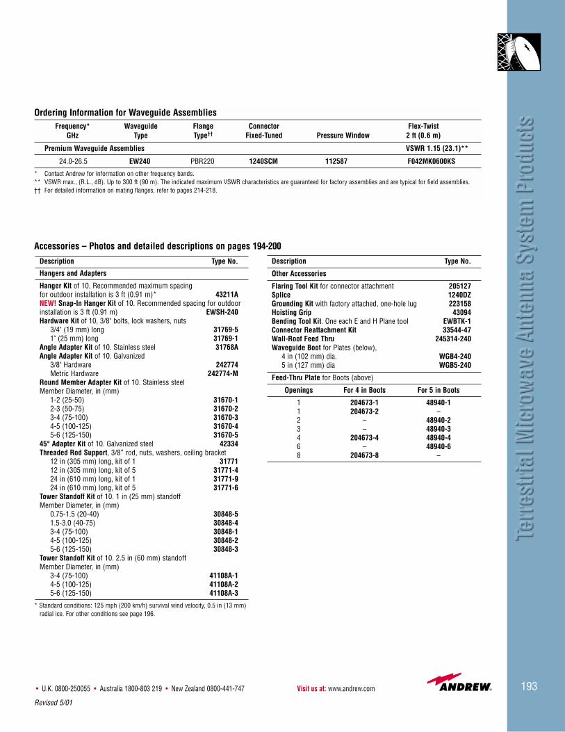
• U.K. 0800-250055 • Australia 1800-803 219 • New Zealand 0800-441-747 Visit us at: www.andrew.com 193
Ordering Information for Waveguide AssembliesFrequency* Waveguide Flange Connector Flex-Twist
GHz Type Type†† Fixed-Tuned Pressure Window 2 ft (0.6 m)
Premium Waveguide Assemblies VSWR 1.15 (23.1)**
24.0-26.5 EW240 PBR220 1240SCM 112587 F042MK0600KS
* Contact Andrew for information on other frequency bands. ** VSWR max., (R.L., dB). Up to 300 ft (90 m). The indicated maximum VSWR characteristics are guaranteed for factory assemblies and are typical for field assemblies.†† For detailed information on mating flanges, refer to pages 214-218.
Description Type No.
Hangers and Adapters
Hanger Kit of 10, Recommended maximum spacingfor outdoor installation is 3 ft (0.91 m)* 43211ANEW! Snap-In Hanger Kit of 10. Recommended spacing for outdoor installation is 3 ft (0.91 m) EWSH-240Hardware Kit of 10, 3/8" bolts, lock washers, nuts
3/4" (19 mm) long 31769-51" (25 mm) long 31769-1
Angle Adapter Kit of 10. Stainless steel 31768AAngle Adapter Kit of 10. Galvanized
3/8" Hardware 242774Metric Hardware 242774-M
Round Member Adapter Kit of 10. Stainless steelMember Diameter, in (mm)
1-2 (25-50) 31670-12-3 (50-75) 31670-23-4 (75-100) 31670-34-5 (100-125) 31670-45-6 (125-150) 31670-5
45° Adapter Kit of 10. Galvanized steel 42334Threaded Rod Support, 3/8” rod, nuts, washers, ceiling bracket
12 in (305 mm) long, kit of 1 3177112 in (305 mm) long, kit of 5 31771-424 in (610 mm) long, kit of 1 31771-924 in (610 mm) long, kit of 5 31771-6
Tower Standoff Kit of 10. 1 in (25 mm) standoffMember Diameter, in (mm)
0.75-1.5 (20-40) 30848-51.5-3.0 (40-75) 30848-43-4 (75-100) 30848-14-5 (100-125) 30848-25-6 (125-150) 30848-3
Tower Standoff Kit of 10. 2.5 in (60 mm) standoffMember Diameter, in (mm)
3-4 (75-100) 41108A-14-5 (100-125) 41108A-25-6 (125-150) 41108A-3
* Standard conditions: 125 mph (200 km/h) survival wind velocity, 0.5 in (13 mm) radial ice. For other conditions see page 196.
Description Type No.
Other Accessories
Flaring Tool Kit for connector attachment 205127Splice 1240DZGrounding Kit with factory attached, one-hole lug 223158Hoisting Grip 43094Bending Tool Kit. One each E and H Plane tool EWBTK-1Connector Reattachment Kit 33544-47Wall-Roof Feed Thru 245314-240Waveguide Boot for Plates (below),
4 in (102 mm) dia. WGB4-2405 in (127 mm) dia WGB5-240
Feed-Thru Plate for Boots (above)
Openings For 4 in Boots For 5 in Boots
1 204673-1 48940-11 204673-2 –2 – 48940-23 – 48940-34 204673-4 48940-46 – 48940-68 204673-8 –
Accessories – Photos and detailed descriptions on pages 194-200
Revised 5/01

Customer Service Center - Call toll-free from: • U.S.A., Canada and Mexico 1-800-255-1479194
A, B Waveguide Hanger Kit of 10 stainless steel hangers.Mount with 3/8" hardware or adapters.
RecommendedMaximum
For Waveguide Waveguide Photo Hanger Spacing*Type Numbers Hanger Kit Ref. ft (m)
EW17, EWP17 31766A-9 A 6 (1.83)EW20 31766A-10 A 5.5 (1.68)EW28 31766A-11 A 5 (1.52)EW34, EWP34 42396A-15 B 4.5 (1.37)EW37, EWP37, EWP37S 42396A-4 B 4.5( 1.37)EW43, EWP43 42396A-16 B 4 (1.22)EW52, EWP52, EWP52S 42396A-8 B 3.5 (1.07)EW63, EWP63, EWP63S 42396A-7 B 3 (0.91)EW64, EWP64 42396A-1 B 3 (0.91)EW77, EWP77 42396A-11 B 3 (0.91)EW85 42396A-5 B 3 (0.91)EW90, EWP90, EWP90S 42396A-5 B 3 (0.91)EW127A, EWP127A 42396A-9 B 3 (0.91)EW132, EWP132 42396A-9 B 3 (0.91)EW180, EWP180 43211A B 3 (0.91)EW220 43211A B 3 (0.91)EW240 43211A B 3 (0.91)
C Snap-In Hanger Kit of 10Recommended
MaximumFor Waveguide Waveguide Photo Hanger Spacing*Type Numbers Hanger Kit Ref. ft (m)
EW52 EWSH-52 C 3.5 (1.07)EW63 EWSH-63 C 3 (0.91)EW64 EWSH-64 C 3 (0.91)EW77 EWSH-77 C 3 (0.91)EW90 EWSH-90 C 3 (0.91)EW127A EWSH-127A C 3 (0.91)EW132 EWSH-132 C 3 (0.91)EW180 EWSH-180 C 3 (0.91)EW220 EWSH-220 C 3 (0.91)EW249 EWSH-240 C 3 (0.91)
* Standard conditions: 125 mph (200 km/h) survival wind velocity, 0.5 in (13 mm)radial ice. For other conditions see page 196.
D Hardware Kit of 10 stainless steel fillister-head bolts, 3/8 inch lockwashers, and nuts for attachment of hangers to drilled tower members.
3/4 in (19 mm) long ..............................Type 31769-51 in (25 mm) long ..................................Type 31769-1
Elliptical Waveguide Hangers
Heavy-Gauge Stainless SteelConstructionHigh strength and excellent corrosion resistance for long-term reliability.
HELIAX® hangers are designed for easy installation. Theclamp locking bolt and nut are preassembled and captivat-ed to minimize installation labor. Proper tension is easy todetermine. The hanger is simply tightened until there is agap of approximately 5/16" (8 mm) between the clamplegs. The pre-drilled hole for 3/8" or 1/2" mounting hard-ware and slots for round member adapter clamps furthersimplify installation. Many accessories are available toadapt these hangers to most tower configurations.
42396A SeriesGripping TabsPrevent waveguide slippage without the need for a hoisting grip.
Pre-Assembled and Captivated HardwareEliminates the need for field assembly.
Springlike FlexibilityMakes it easy to form the hanger around the waveguideand dampens vibration for long life.
A
B D
C

• U.K. 0800-250055 • Australia 1800-803 219 • New Zealand 0800-441-747 Visit us at: www.andrew.com 195
E Angle Adapter Kit of 10 stainless steel clamps tomount waveguide hangers to angle members up to7/8" (22 mm) thick .................................Type 31768A
Angle Adapter, Galvanized, kit of 10. For mounting cable 1/2" to 2-1/4" cable hangers to angle towermembers up to 3/4" (19mm) thick. Includes hanger attachment hardware.3/8" Hardware .........................................Type 242774Metric Hardware .................................Type 242774-M
F Round Member Adapter Kit of 10 stainless steel clamps to mount hangers to round support members. Two kits are required for use with each EW17 and EW20 hanger kit. One kit is required for all other sizes.Member Diameter, in (mm) Type Number
1 - 2 (25 - 50) 31670-12 - 3 (50 - 75) 31670-23 - 4 (75 - 100) 31670-34 - 5 (100 - 125) 31670-45 - 6 (125 - 150) 31670-5
G 45° Adapter Kit of 10. Use with angle adapter andthreaded rod support kit to place a hanger at a waveguide bend. Galvanized steel ............Type 42334
H Threaded Rod Support Kit. Stainless steel. Use to mount hangers away from supporting structure,under waveguide bridge, inside equipment room and to restrain waveguide bends. Includes 3/8 inch diameter threaded rod, nuts and washers. Attach to ceiling using included ceiling mounting bracket.Attach to angle tower members with 31768A angleadapters. Attach to round tower members with 30848 series tower standoffs.
Kit of 1 Kit of 5
12 inch (305 mm) rod 31771 31771-424 inch (610 mm) rod 31771-9 31771-6
I Tower Standoff Kit of 10 adapters with round member clamps and 3/8 inch hardware. Provides clearance for tower leg flanges.Member Diameter 1 in (25 mm) 2.5 in (60 mm)
in (mm) Standoff Standoff
0.75 - 1.5 (20 - 40) 30848-5 – 1.5 - 3.0 (40 - 75) 30848-4 –3 - 4 (75 - 100) 30848-1 41108A-14 - 5 (100 - 125) 30848-2 41108A-25 - 6 (125 - 150) 30848-3 41108A-3
Standard Hanger Accessories
Hanger/Round Member Adapter
Hanger/Angle Adapter
Hanger/45° Adapter ThreadedRod Support Kit
Hanger/Threaded RodSupport Kit
E
F
B
H
I
H
G
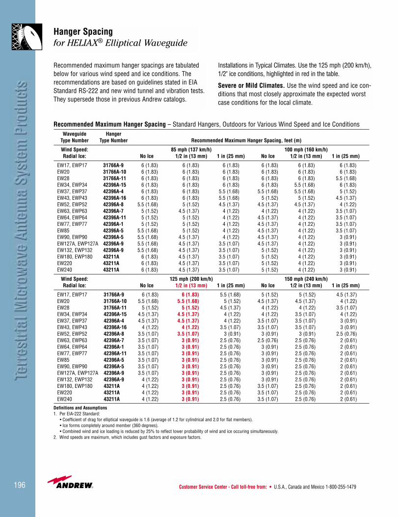
Customer Service Center - Call toll-free from: • U.S.A., Canada and Mexico 1-800-255-1479196
Recommended Maximum Hanger Spacing – Standard Hangers, Outdoors for Various Wind Speed and Ice ConditionsWaveguide Hanger
Type Number Type Number Recommended Maximum Hanger Spacing, feet (m)
Wind Speed: 85 mph (137 km/h) 100 mph (160 km/h)Radial Ice: No Ice 1/2 in (13 mm) 1 in (25 mm) No Ice 1/2 in (13 mm) 1 in (25 mm)
EW17, EWP17 31766A-9 6 (1.83) 6 (1.83) 6 (1.83) 6 (1.83) 6 (1.83) 6 (1.83)EW20 31766A-10 6 (1.83) 6 (1.83) 6 (1.83) 6 (1.83) 6 (1.83) 6 (1.83)EW28 31766A-11 6 (1.83) 6 (1.83) 6 (1.83) 6 (1.83) 6 (1.83) 5.5 (1.68)EW34, EWP34 42396A-15 6 (1.83) 6 (1.83) 6 (1.83) 6 (1.83) 5.5 (1.68) 6 (1.83)EW37, EWP37 42396A-4 6 (1.83) 6 (1.83) 5.5 (1.68) 5.5 (1.68) 5.5 (1.68) 5 (1.52)EW43, EWP43 42396A-16 6 (1.83) 6 (1.83) 5.5 (1.68) 5 (1.52) 5 (1.52) 4.5 (1.37)EW52, EWP52 42396A-8 5.5 (1.68) 5 (1.52) 4.5 (1.37) 4.5 (1.37) 4.5 (1.37) 4 (1.22)EW63, EWP63 42396A-7 5 (1.52) 4.5 (1.37) 4 (1.22) 4 (1.22) 4 (1.22) 3.5 (1.07)EW64, EWP64 42396A-11 5 (1.52) 5 (1.52) 4 (1.22) 4.5 (1.37) 4 (1.22) 3.5 (1.07)EW77, EWP77 42396A-1 5 (1.52) 5 (1.52) 4 (1.22) 4.5 (1.37) 4 (1.22) 3.5 (1.07)EW85 42396A-5 5.5 (1.68) 5 (1.52) 4 (1.22) 4.5 (1.37) 4 (1.22) 3.5 (1.07)EW90, EWP90 42396A-5 5.5 (1.68) 4.5 (1.37) 4 (1.22) 4.5 (1.37) 4 (1.22) 3 (0.91)EW127A, EWP127A 42396A-9 5.5 (1.68) 4.5 (1.37) 3.5 (1.07) 4.5 (1.37) 4 (1.22) 3 (0.91)EW132, EWP132 42396A-9 5.5 (1.68) 4.5 (1.37) 3.5 (1.07) 5 (1.52) 4 (1.22) 3 (0.91)EW180, EWP180 43211A 6 (1.83) 4.5 (1.37) 3.5 (1.07) 5 (1.52) 4 (1.22) 3 (0.91)EW220 43211A 6 (1.83) 4.5 (1.37) 3.5 (1.07) 5 (1.52) 4 (1.22) 3 (0.91)EW240 43211A 6 (1.83) 4.5 (1.37) 3.5 (1.07) 5 (1.52) 4 (1.22) 3 (0.91)
Wind Speed: 125 mph (200 km/h) 150 mph (240 km/h)Radial Ice: No Ice 1/2 in (13 mm) 1 in (25 mm) No Ice 1/2 in (13 mm) 1 in (25 mm)
EW17, EWP17 31766A-9 6 (1.83) 6 (1.83) 5.5 (1.68) 5 (1.52) 5 (1.52) 4.5 (1.37)EW20 31766A-10 5.5 (1.68) 5.5 (1.68) 5 (1.52) 4.5 (1.37) 4.5 (1.37) 4 (1.22)EW28 31766A-11 5 (1.52) 5 (1.52) 4.5 (1.37) 4 (1.22) 4 (1.22) 3.5 (1.07)EW34, EWP34 42396A-15 4.5 (1.37) 4.5 (1.37) 4 (1.22) 4 (1.22) 3.5 (1.07) 4 (1.22)EW37, EWP37 42396A-4 4.5 (1.37) 4.5 (1.37) 4 (1.22) 3.5 (1.07) 3.5 (1.07) 3 (0.91)EW43, EWP43 42396A-16 4 (1.22) 4 (1.22) 3.5 (1.07) 3.5 (1.07) 3.5 (1.07) 3 (0.91)EW52, EWP52 42396A-8 3.5 (1.07) 3.5 (1.07) 3 (0.91) 3 (0.91) 3 (0.91) 2.5 (0.76)EW63, EWP63 42396A-7 3.5 (1.07) 3 (0.91) 2.5 (0.76) 2.5 (0.76) 2.5 (0.76) 2 (0.61)EW64, EWP64 42396A-1 3.5 (1.07) 3 (0.91) 2.5 (0.76) 3 (0.91) 2.5 (0.76) 2 (0.61)EW77, EWP77 42396A-11 3.5 (1.07) 3 (0.91) 2.5 (0.76) 3 (0.91) 2.5 (0.76) 2 (0.61)EW85 42396A-5 3.5 (1.07) 3 (0.91) 2.5 (0.76) 3 (0.91) 2.5 (0.76) 2 (0.61)EW90, EWP90 42396A-5 3.5 (1.07) 3 (0.91) 2.5 (0.76) 3 (0.91) 2.5 (0.76) 2 (0.61)EW127A, EWP127A 42396A-9 3.5 (1.07) 3 (0.91) 2.5 (0.76) 3 (0.91) 2.5 (0.76) 2 (0.61)EW132, EWP132 42396A-9 4 (1.22) 3 (0.91) 2.5 (0.76) 3 (0.91) 2.5 (0.76) 2 (0.61)EW180, EWP180 43211A 4 (1.22) 3 (0.91) 2.5 (0.76) 3.5 (1.07) 2.5 (0.76) 2 (0.61)EW220 43211A 4 (1.22) 3 (0.91) 2.5 (0.76) 3.5 (1.07) 2.5 (0.76) 2 (0.61)EW240 43211A 4 (1.22) 3 (0.91) 2.5 (0.76) 3.5 (1.07) 2.5 (0.76) 2 (0.61)
Definitions and Assumptions1. Per EIA-222 Standard:
• Coefficient of drag for elliptical waveguide is 1.6 (average of 1.2 for cylindrical and 2.0 for flat members).• Ice forms completely around member (360 degrees).• Combined wind and ice loading is reduced by 25% to reflect lower probability of wind and ice occuring simultaneously.
2. Wind speeds are maximum, which includes gust factors and exposure factors.
Hanger Spacing for HELIAX® Elliptical Waveguide
Recommended maximum hanger spacings are tabulatedbelow for various wind speed and ice conditions. The recommendations are based on guidelines stated in EIAStandard RS-222 and new wind tunnel and vibration tests.They supersede those in previous Andrew catalogs.
Installations in Typical Climates. Use the 125 mph (200 km/h),1/2" ice conditions, highlighted in red in the table.
Severe or Mild Climates. Use the wind speed and ice con-ditions that most closely approximate the expected worstcase conditions for the local climate.
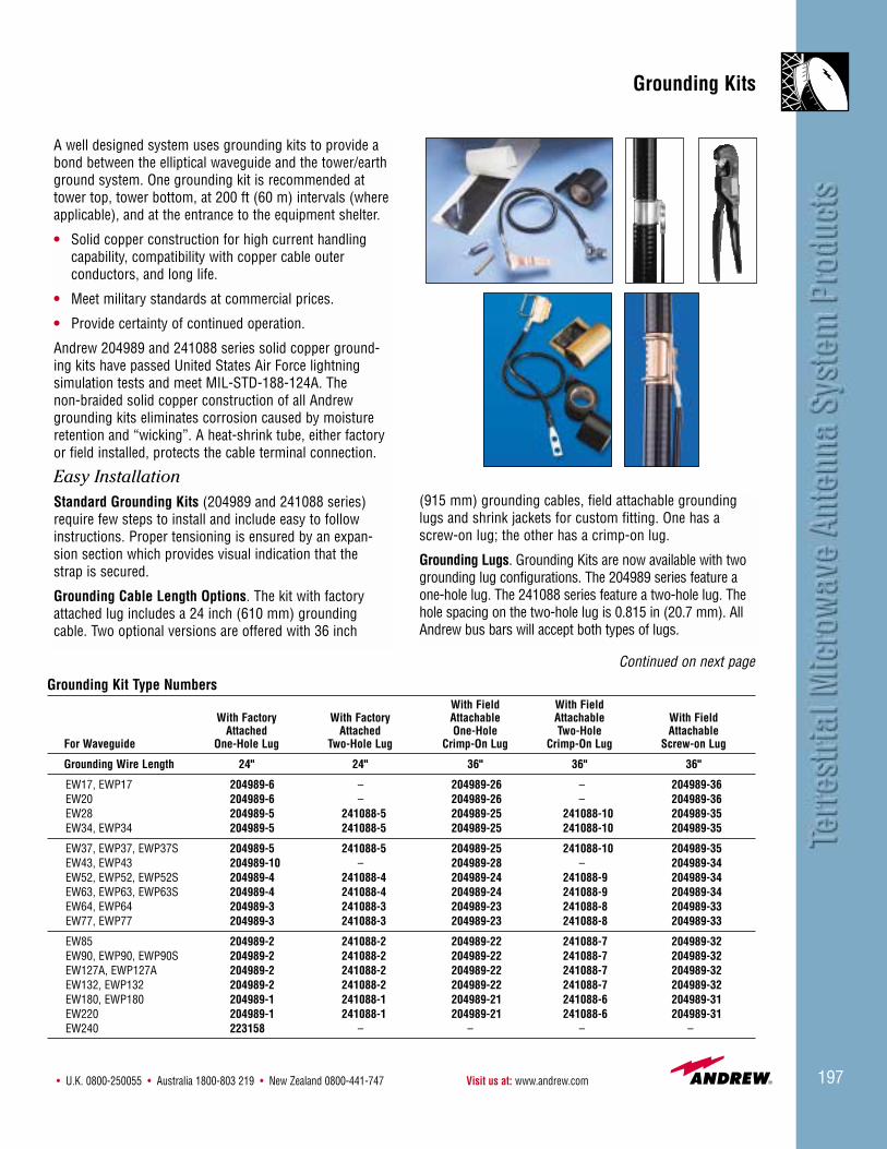
• U.K. 0800-250055 • Australia 1800-803 219 • New Zealand 0800-441-747 Visit us at: www.andrew.com 197
Grounding Kit Type NumbersWith Field With Field
With Factory With Factory Attachable Attachable With FieldAttached Attached One-Hole Two-Hole Attachable
For Waveguide One-Hole Lug Two-Hole Lug Crimp-On Lug Crimp-On Lug Screw-on Lug
Grounding Wire Length 24" 24" 36" 36" 36"
EW17, EWP17 204989-6 – 204989-26 – 204989-36EW20 204989-6 – 204989-26 – 204989-36EW28 204989-5 241088-5 204989-25 241088-10 204989-35EW34, EWP34 204989-5 241088-5 204989-25 241088-10 204989-35
EW37, EWP37, EWP37S 204989-5 241088-5 204989-25 241088-10 204989-35EW43, EWP43 204989-10 – 204989-28 – 204989-34EW52, EWP52, EWP52S 204989-4 241088-4 204989-24 241088-9 204989-34EW63, EWP63, EWP63S 204989-4 241088-4 204989-24 241088-9 204989-34EW64, EWP64 204989-3 241088-3 204989-23 241088-8 204989-33EW77, EWP77 204989-3 241088-3 204989-23 241088-8 204989-33
EW85 204989-2 241088-2 204989-22 241088-7 204989-32EW90, EWP90, EWP90S 204989-2 241088-2 204989-22 241088-7 204989-32EW127A, EWP127A 204989-2 241088-2 204989-22 241088-7 204989-32EW132, EWP132 204989-2 241088-2 204989-22 241088-7 204989-32EW180, EWP180 204989-1 241088-1 204989-21 241088-6 204989-31EW220 204989-1 241088-1 204989-21 241088-6 204989-31EW240 223158 – – – –
A well designed system uses grounding kits to provide abond between the elliptical waveguide and the tower/earthground system. One grounding kit is recommended attower top, tower bottom, at 200 ft (60 m) intervals (whereapplicable), and at the entrance to the equipment shelter.
• Solid copper construction for high current handling capability, compatibility with copper cable outer conductors, and long life.
• Meet military standards at commercial prices.
• Provide certainty of continued operation.
Andrew 204989 and 241088 series solid copper ground-ing kits have passed United States Air Force lightning simulation tests and meet MIL-STD-188-124A. The non-braided solid copper construction of all Andrewgrounding kits eliminates corrosion caused by moistureretention and “wicking”. A heat-shrink tube, either factoryor field installed, protects the cable terminal connection.
Easy InstallationStandard Grounding Kits (204989 and 241088 series)require few steps to install and include easy to followinstructions. Proper tensioning is ensured by an expan-sion section which provides visual indication that thestrap is secured.
Grounding Cable Length Options. The kit with factoryattached lug includes a 24 inch (610 mm) groundingcable. Two optional versions are offered with 36 inch
Grounding Kits
Continued on next page
(915 mm) grounding cables, field attachable groundinglugs and shrink jackets for custom fitting. One has ascrew-on lug; the other has a crimp-on lug.
Grounding Lugs. Grounding Kits are now available with twogrounding lug configurations. The 204989 series feature aone-hole lug. The 241088 series feature a two-hole lug. Thehole spacing on the two-hole lug is 0.815 in (20.7 mm). AllAndrew bus bars will accept both types of lugs.
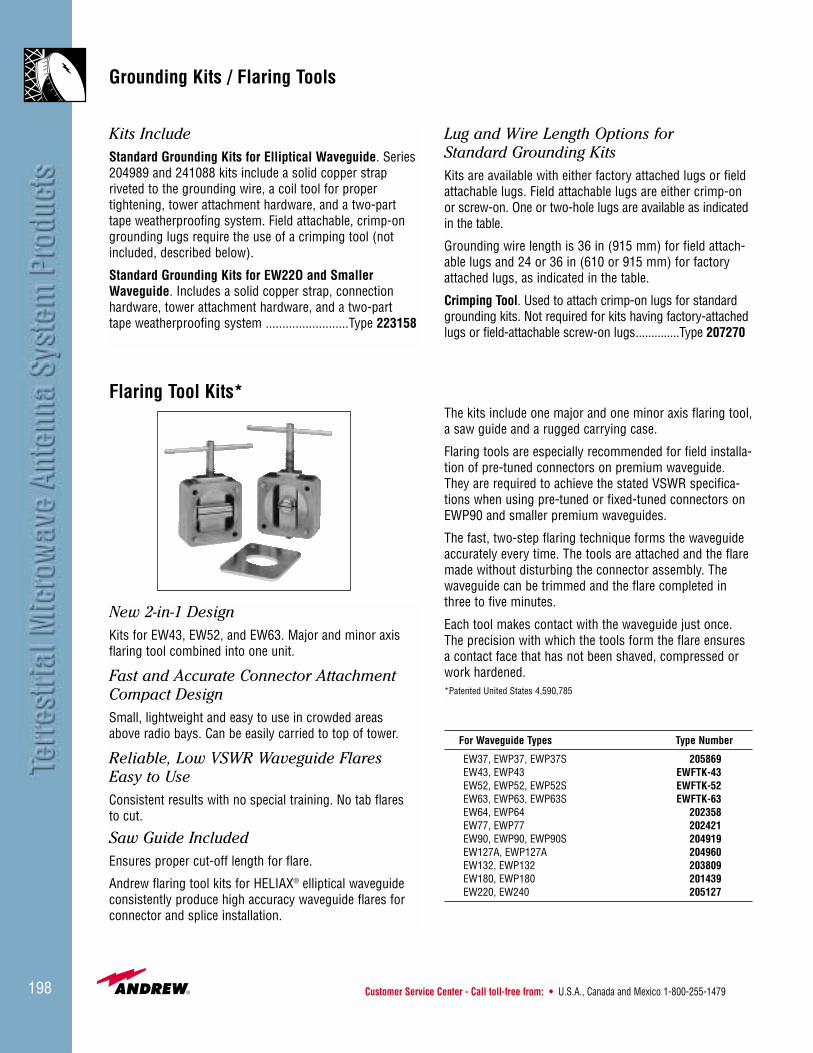
Customer Service Center - Call toll-free from: • U.S.A., Canada and Mexico 1-800-255-1479198
New 2-in-1 DesignKits for EW43, EW52, and EW63. Major and minor axisflaring tool combined into one unit.
Fast and Accurate Connector AttachmentCompact DesignSmall, lightweight and easy to use in crowded areasabove radio bays. Can be easily carried to top of tower.
Reliable, Low VSWR Waveguide FlaresEasy to UseConsistent results with no special training. No tab flaresto cut.
Saw Guide IncludedEnsures proper cut-off length for flare.
Andrew flaring tool kits for HELIAX® elliptical waveguideconsistently produce high accuracy waveguide flares forconnector and splice installation.
For Waveguide Types Type Number
EW37, EWP37, EWP37S 205869EW43, EWP43 EWFTK-43EW52, EWP52, EWP52S EWFTK-52EW63, EWP63, EWP63S EWFTK-63EW64, EWP64 202358EW77, EWP77 202421EW90, EWP90, EWP90S 204919EW127A, EWP127A 204960EW132, EWP132 203809EW180, EWP180 201439EW220, EW240 205127
The kits include one major and one minor axis flaring tool,a saw guide and a rugged carrying case.
Flaring tools are especially recommended for field installa-tion of pre-tuned connectors on premium waveguide.They are required to achieve the stated VSWR specifica-tions when using pre-tuned or fixed-tuned connectors onEWP90 and smaller premium waveguides.
The fast, two-step flaring technique forms the waveguideaccurately every time. The tools are attached and the flaremade without disturbing the connector assembly. Thewaveguide can be trimmed and the flare completed inthree to five minutes.
Each tool makes contact with the waveguide just once.The precision with which the tools form the flare ensuresa contact face that has not been shaved, compressed orwork hardened.*Patented United States 4,590,785
Kits IncludeStandard Grounding Kits for Elliptical Waveguide. Series204989 and 241088 kits include a solid copper strap riveted to the grounding wire, a coil tool for proper tightening, tower attachment hardware, and a two-parttape weatherproofing system. Field attachable, crimp-ongrounding lugs require the use of a crimping tool (notincluded, described below).
Standard Grounding Kits for EW22O and SmallerWaveguide. Includes a solid copper strap, connectionhardware, tower attachment hardware, and a two-parttape weatherproofing system .........................Type 223158
Lug and Wire Length Options for Standard Grounding KitsKits are available with either factory attached lugs or fieldattachable lugs. Field attachable lugs are either crimp-onor screw-on. One or two-hole lugs are available as indicatedin the table.
Grounding wire length is 36 in (915 mm) for field attach-able lugs and 24 or 36 in (610 or 915 mm) for factoryattached lugs, as indicated in the table.
Crimping Tool. Used to attach crimp-on lugs for standardgrounding kits. Not required for kits having factory-attachedlugs or field-attachable screw-on lugs..............Type 207270
Grounding Kits / Flaring Tools
Flaring Tool Kits*
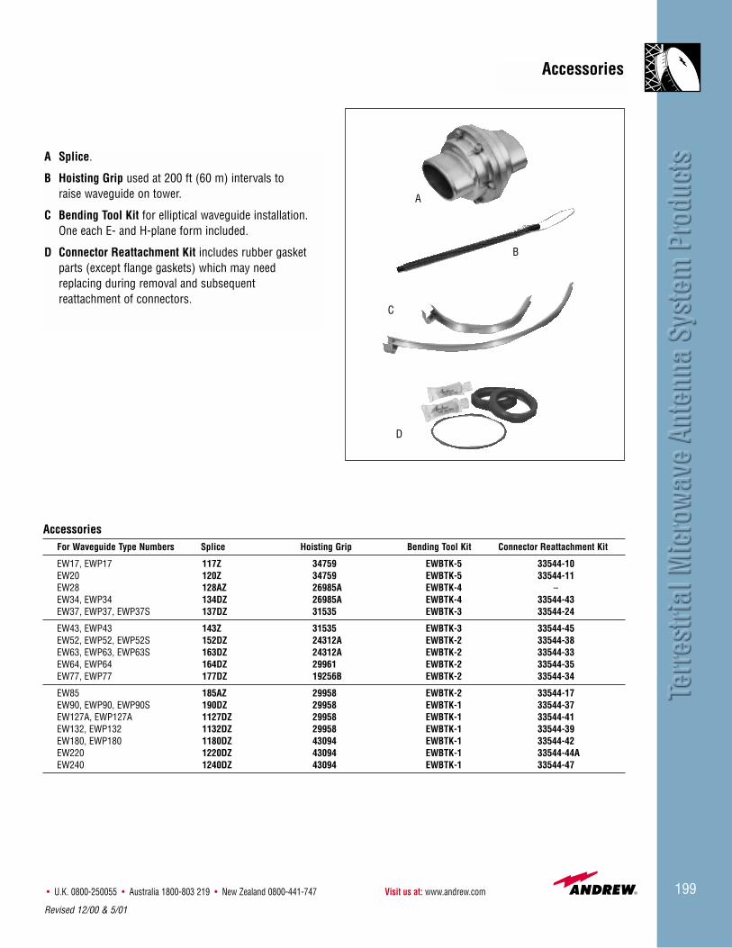
• U.K. 0800-250055 • Australia 1800-803 219 • New Zealand 0800-441-747 Visit us at: www.andrew.com 199
AccessoriesFor Waveguide Type Numbers Splice Hoisting Grip Bending Tool Kit Connector Reattachment Kit
EW17, EWP17 117Z 34759 EWBTK-5 33544-10EW20 120Z 34759 EWBTK-5 33544-11EW28 128AZ 26985A EWBTK-4 –EW34, EWP34 134DZ 26985A EWBTK-4 33544-43EW37, EWP37, EWP37S 137DZ 31535 EWBTK-3 33544-24
EW43, EWP43 143Z 31535 EWBTK-3 33544-45EW52, EWP52, EWP52S 152DZ 24312A EWBTK-2 33544-38EW63, EWP63, EWP63S 163DZ 24312A EWBTK-2 33544-33EW64, EWP64 164DZ 29961 EWBTK-2 33544-35EW77, EWP77 177DZ 19256B EWBTK-2 33544-34
EW85 185AZ 29958 EWBTK-2 33544-17EW90, EWP90, EWP90S 190DZ 29958 EWBTK-1 33544-37EW127A, EWP127A 1127DZ 29958 EWBTK-1 33544-41EW132, EWP132 1132DZ 29958 EWBTK-1 33544-39EW180, EWP180 1180DZ 43094 EWBTK-1 33544-42EW220 1220DZ 43094 EWBTK-1 33544-44AEW240 1240DZ 43094 EWBTK-1 33544-47
A Splice.
B Hoisting Grip used at 200 ft (60 m) intervals to raise waveguide on tower.
C Bending Tool Kit for elliptical waveguide installation. One each E- and H-plane form included.
D Connector Reattachment Kit includes rubber gasket parts (except flange gaskets) which may need replacing during removal and subsequent reattachment of connectors.
Accessories
A
B
C
D
Revised 12/00 & 5/01
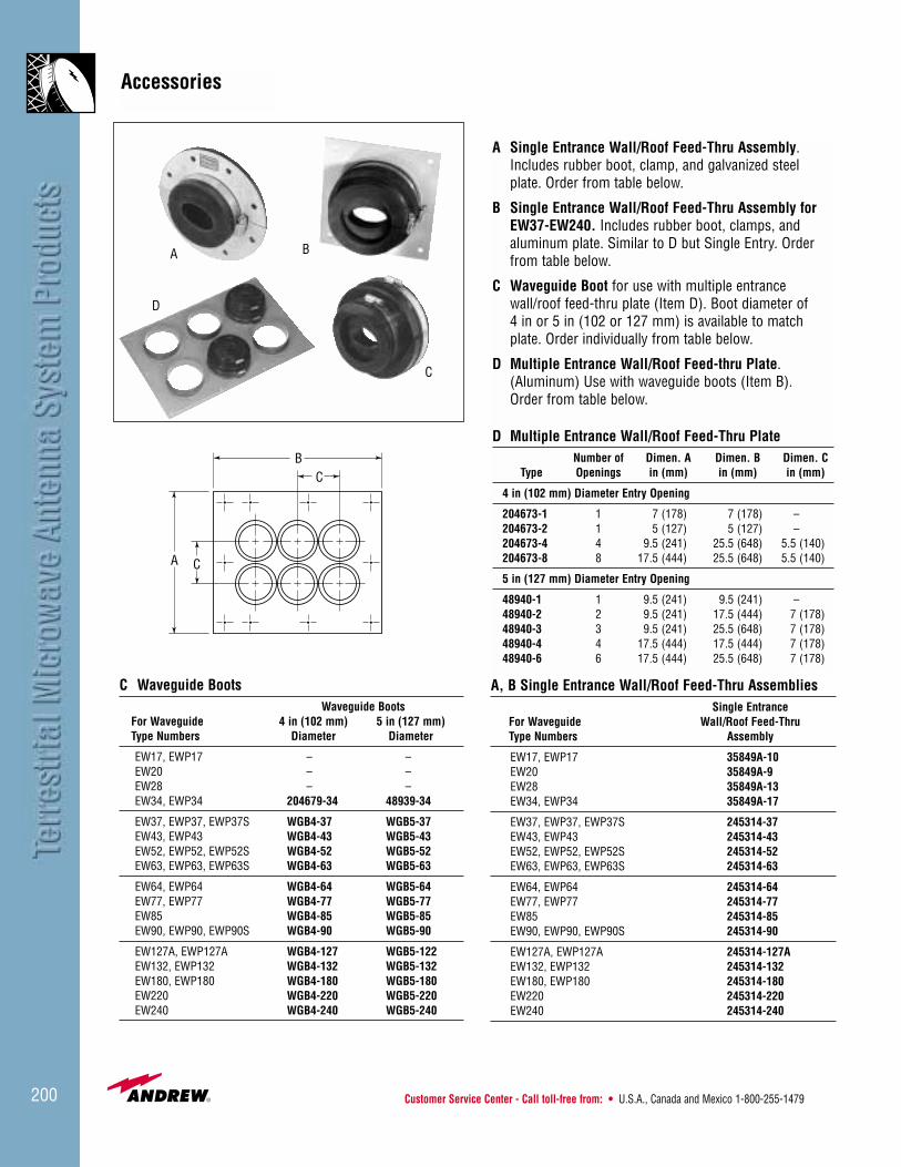
Customer Service Center - Call toll-free from: • U.S.A., Canada and Mexico 1-800-255-1479200
A Single Entrance Wall/Roof Feed-Thru Assembly. Includes rubber boot, clamp, and galvanized steel plate. Order from table below.
B Single Entrance Wall/Roof Feed-Thru Assembly forEW37-EW240. Includes rubber boot, clamps, and aluminum plate. Similar to D but Single Entry. Orderfrom table below.
C Waveguide Boot for use with multiple entrance wall/roof feed-thru plate (Item D). Boot diameter of 4 in or 5 in (102 or 127 mm) is available to match plate. Order individually from table below.
D Multiple Entrance Wall/Roof Feed-thru Plate. (Aluminum) Use with waveguide boots (Item B). Order from table below.
D Multiple Entrance Wall/Roof Feed-Thru PlateNumber of Dimen. A Dimen. B Dimen. C
Type Openings in (mm) in (mm) in (mm)
4 in (102 mm) Diameter Entry Opening
204673-1 1 7 (178) 7 (178) – 204673-2 1 5 (127) 5 (127) – 204673-4 4 9.5 (241) 25.5 (648) 5.5 (140)204673-8 8 17.5 (444) 25.5 (648) 5.5 (140)
5 in (127 mm) Diameter Entry Opening
48940-1 1 9.5 (241) 9.5 (241) –48940-2 2 9.5 (241) 17.5 (444) 7 (178)48940-3 3 9.5 (241) 25.5 (648) 7 (178)48940-4 4 17.5 (444) 17.5 (444) 7 (178)48940-6 6 17.5 (444) 25.5 (648) 7 (178)
C Waveguide BootsWaveguide Boots
For Waveguide 4 in (102 mm) 5 in (127 mm)Type Numbers Diameter Diameter
EW17, EWP17 – –EW20 – –EW28 – – EW34, EWP34 204679-34 48939-34
EW37, EWP37, EWP37S WGB4-37 WGB5-37EW43, EWP43 WGB4-43 WGB5-43EW52, EWP52, EWP52S WGB4-52 WGB5-52EW63, EWP63, EWP63S WGB4-63 WGB5-63
EW64, EWP64 WGB4-64 WGB5-64EW77, EWP77 WGB4-77 WGB5-77EW85 WGB4-85 WGB5-85EW90, EWP90, EWP90S WGB4-90 WGB5-90
EW127A, EWP127A WGB4-127 WGB5-122EW132, EWP132 WGB4-132 WGB5-132EW180, EWP180 WGB4-180 WGB5-180EW220 WGB4-220 WGB5-220EW240 WGB4-240 WGB5-240
A, B Single Entrance Wall/Roof Feed-Thru AssembliesSingle Entrance
For Waveguide Wall/Roof Feed-ThruType Numbers Assembly
EW17, EWP17 35849A-10EW20 35849A-9EW28 35849A-13EW34, EWP34 35849A-17
EW37, EWP37, EWP37S 245314-37EW43, EWP43 245314-43EW52, EWP52, EWP52S 245314-52EW63, EWP63, EWP63S 245314-63
EW64, EWP64 245314-64EW77, EWP77 245314-77EW85 245314-85EW90, EWP90, EWP90S 245314-90
EW127A, EWP127A 245314-127AEW132, EWP132 245314-132EW180, EWP180 245314-180EW220 245314-220EW240 245314-240
CB
CA
Accessories
A
C
D
B

• U.K. 0800-250055 • Australia 1800-803 219 • New Zealand 0800-441-747 Visit us at: www.andrew.com 201
The Andrew hybrid T reflectometer is a unique and highlydirective test component useful for measuring return lossor VSWR in waveguide systems. The reflectometer utilizesa precision hybrid T junction to separate the incident andreflected waves at the input of the system under test.
In addition to the reflectometer, a signal generator andequipment to detect and display return loss or VSWR arenecessary. For information on operation of the Andrewhybrid T reflectometer, request Bulletin 37260.
To order, specify Type Number from the table. A calibrationload, a termination load and carrying case are included.
Elliptical Waveguide Sliding Load. Spear type termina-tion load used at far end of bulk reels to terminate wave-guide without attaching a connector and calibration load.
Elliptical Waveguide Sliding LoadsWaveguide Type Frequency VSWR, Max.Type No. Band, GHz (R.L., dB)
EW37 40502-37 3.4-4.2 1.052 (32)EW44 40502-44 4.4-5.0 1.02 (40)EW52 40502-52 5.925-6.425 1.02 (40)EW63 40502-63 6.425-7.125 1.02 (40)EW90 40502-90 10.5-11.7) 1.02 (40)
Hybrid T Reflectometer
Revised 5/01
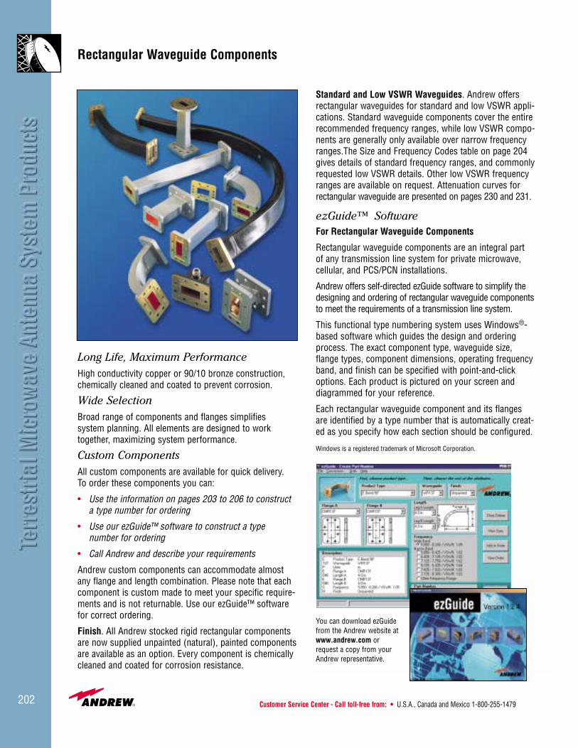
Customer Service Center - Call toll-free from: • U.S.A., Canada and Mexico 1-800-255-1479202
Rectangular Waveguide Components
Long Life, Maximum PerformanceHigh conductivity copper or 90/10 bronze construction,chemically cleaned and coated to prevent corrosion.
Wide SelectionBroad range of components and flanges simplifies system planning. All elements are designed to worktogether, maximizing system performance.
Custom ComponentsAll custom components are available for quick delivery. To order these components you can:
• Use the information on pages 203 to 206 to construct a type number for ordering
• Use our ezGuide™ software to construct a type number for ordering
• Call Andrew and describe your requirements
Andrew custom components can accommodate almostany flange and length combination. Please note that eachcomponent is custom made to meet your specific require-ments and is not returnable. Use our ezGuide™ softwarefor correct ordering.
Finish. All Andrew stocked rigid rectangular componentsare now supplied unpainted (natural), painted componentsare available as an option. Every component is chemicallycleaned and coated for corrosion resistance.
Standard and Low VSWR Waveguides. Andrew offersrectangular waveguides for standard and low VSWR appli-cations. Standard waveguide components cover the entirerecommended frequency ranges, while low VSWR compo-nents are generally only available over narrow frequencyranges.The Size and Frequency Codes table on page 204gives details of standard frequency ranges, and commonlyrequested low VSWR details. Other low VSWR frequencyranges are available on request. Attenuation curves forrectangular waveguide are presented on pages 230 and 231.
ezGuide™ Software For Rectangular Waveguide Components
Rectangular waveguide components are an integral part of any transmission line system for private microwave,cellular, and PCS/PCN installations.
Andrew offers self-directed ezGuide software to simplify thedesigning and ordering of rectangular waveguide componentsto meet the requirements of a transmission line system.
This functional type numbering system uses Windows®-based software which guides the design and orderingprocess. The exact component type, waveguide size,flange types, component dimensions, operating frequencyband, and finish can be specified with point-and-clickoptions. Each product is pictured on your screen and diagrammed for your reference.
Each rectangular waveguide component and its flangesare identified by a type number that is automatically creat-ed as you specify how each section should be configured.
Windows is a registered trademark of Microsoft Corporation.
You can download ezGuidefrom the Andrew website atwww.andrew.com orrequest a copy from yourAndrew representative.
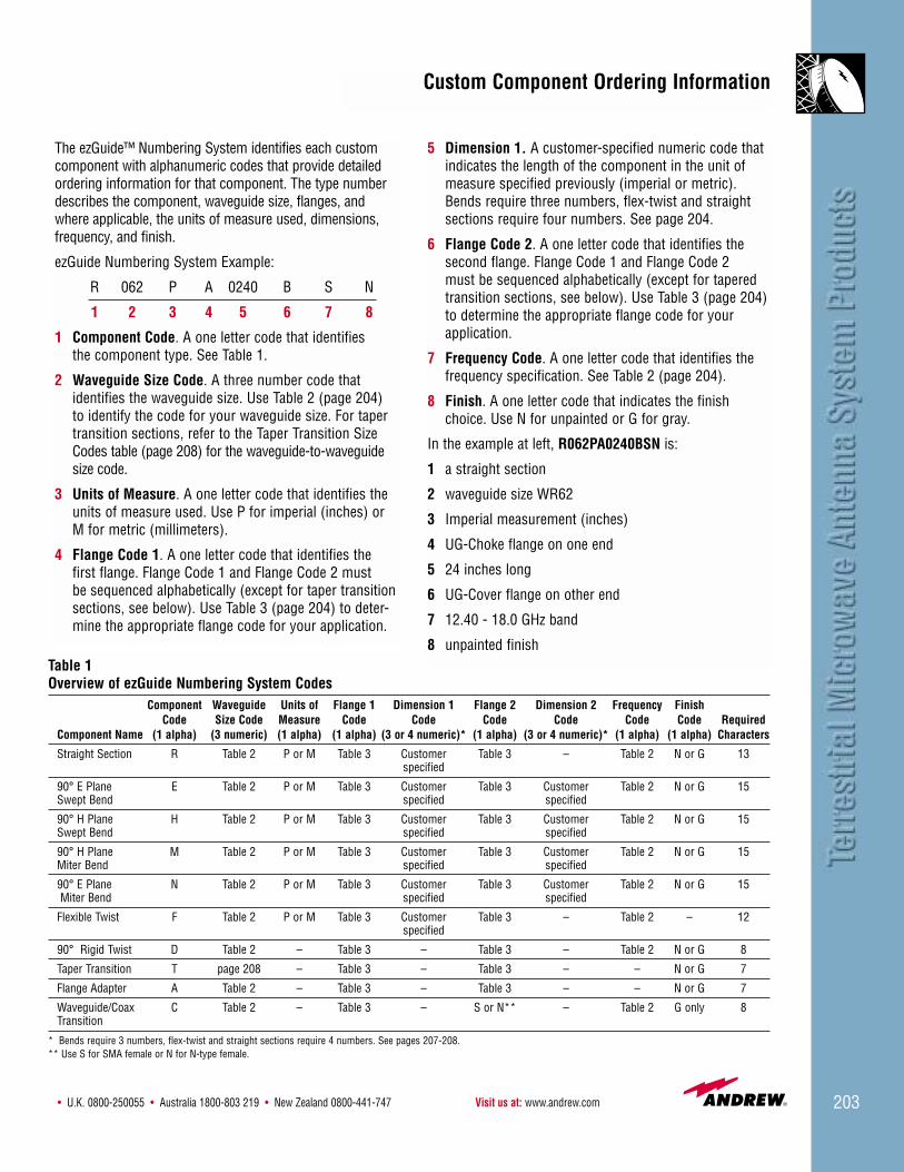
• U.K. 0800-250055 • Australia 1800-803 219 • New Zealand 0800-441-747 Visit us at: www.andrew.com 203
The ezGuide™ Numbering System identifies each customcomponent with alphanumeric codes that provide detailedordering information for that component. The type numberdescribes the component, waveguide size, flanges, andwhere applicable, the units of measure used, dimensions,frequency, and finish.
ezGuide Numbering System Example:
R 062 P A 0240 B S N
1 2 3 4 5 6 7 8
1 Component Code. A one letter code that identifies the component type. See Table 1.
2 Waveguide Size Code. A three number code that identifies the waveguide size. Use Table 2 (page 204) to identify the code for your waveguide size. For taper transition sections, refer to the Taper Transition Size Codes table (page 208) for the waveguide-to-waveguide size code.
3 Units of Measure. A one letter code that identifies the units of measure used. Use P for imperial (inches) or M for metric (millimeters).
4 Flange Code 1. A one letter code that identifies the first flange. Flange Code 1 and Flange Code 2 must be sequenced alphabetically (except for taper transitionsections, see below). Use Table 3 (page 204) to deter-mine the appropriate flange code for your application.
5 Dimension 1. A customer-specified numeric code that indicates the length of the component in the unit of measure specified previously (imperial or metric). Bends require three numbers, flex-twist and straight sections require four numbers. See page 204.
6 Flange Code 2. A one letter code that identifies the second flange. Flange Code 1 and Flange Code 2 must be sequenced alphabetically (except for tapered transition sections, see below). Use Table 3 (page 204)to determine the appropriate flange code for your application.
7 Frequency Code. A one letter code that identifies the frequency specification. See Table 2 (page 204).
8 Finish. A one letter code that indicates the finish choice. Use N for unpainted or G for gray.
In the example at left, R062PA0240BSN is:
1 a straight section
2 waveguide size WR62
3 Imperial measurement (inches)
4 UG-Choke flange on one end
5 24 inches long
6 UG-Cover flange on other end
7 12.40 - 18.0 GHz band
8 unpainted finishTable 1Overview of ezGuide Numbering System Codes
Component Waveguide Units of Flange 1 Dimension 1 Flange 2 Dimension 2 Frequency FinishCode Size Code Measure Code Code Code Code Code Code Required
Component Name (1 alpha) (3 numeric) (1 alpha) (1 alpha) (3 or 4 numeric)* (1 alpha) (3 or 4 numeric)* (1 alpha) (1 alpha) Characters
Straight Section R Table 2 P or M Table 3 Customer Table 3 – Table 2 N or G 13specified
90° E Plane E Table 2 P or M Table 3 Customer Table 3 Customer Table 2 N or G 15Swept Bend specified specified
90° H Plane H Table 2 P or M Table 3 Customer Table 3 Customer Table 2 N or G 15Swept Bend specified specified
90° H Plane M Table 2 P or M Table 3 Customer Table 3 Customer Table 2 N or G 15Miter Bend specified specified
90° E Plane N Table 2 P or M Table 3 Customer Table 3 Customer Table 2 N or G 15Miter Bend specified specified
Flexible Twist F Table 2 P or M Table 3 Customer Table 3 – Table 2 – 12specified
90° Rigid Twist D Table 2 – Table 3 – Table 3 – Table 2 N or G 8
Taper Transition T page 208 – Table 3 – Table 3 – – N or G 7
Flange Adapter A Table 2 – Table 3 – Table 3 – – N or G 7
Waveguide/Coax C Table 2 – Table 3 – S or N** – Table 2 G only 8Transition
* Bends require 3 numbers, flex-twist and straight sections require 4 numbers. See pages 207-208.** Use S for SMA female or N for N-type female.
Custom Component Ordering Information
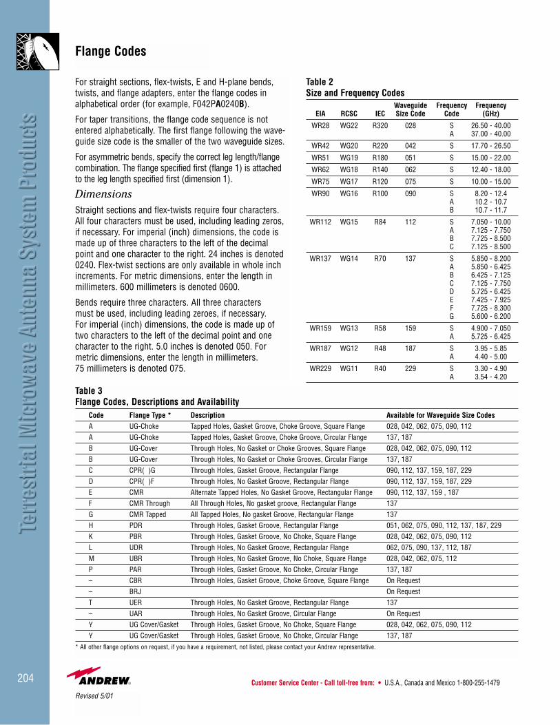
Customer Service Center - Call toll-free from: • U.S.A., Canada and Mexico 1-800-255-1479204
For straight sections, flex-twists, E and H-plane bends,twists, and flange adapters, enter the flange codes inalphabetical order (for example, F042PA0240B).
For taper transitions, the flange code sequence is notentered alphabetically. The first flange following the wave-guide size code is the smaller of the two waveguide sizes.
For asymmetric bends, specify the correct leg length/flangecombination. The flange specified first (flange 1) is attachedto the leg length specified first (dimension 1).
DimensionsStraight sections and flex-twists require four characters.All four characters must be used, including leading zeros,if necessary. For imperial (inch) dimensions, the code ismade up of three characters to the left of the decimalpoint and one character to the right. 24 inches is denoted0240. Flex-twist sections are only available in whole inchincrements. For metric dimensions, enter the length inmillimeters. 600 millimeters is denoted 0600.
Bends require three characters. All three characters must be used, including leading zeroes, if necessary. For imperial (inch) dimensions, the code is made up oftwo characters to the left of the decimal point and onecharacter to the right. 5.0 inches is denoted 050. For metric dimensions, enter the length in millimeters. 75 millimeters is denoted 075.
Table 3Flange Codes, Descriptions and Availability
Code Flange Type * Description Available for Waveguide Size CodesA UG-Choke Tapped Holes, Gasket Groove, Choke Groove, Square Flange 028, 042, 062, 075, 090, 112A UG-Choke Tapped Holes, Gasket Groove, Choke Groove, Circular Flange 137, 187B UG-Cover Through Holes, No Gasket or Choke Grooves, Square Flange 028, 042, 062, 075, 090, 112B UG-Cover Through Holes, No Gasket or Choke Grooves, Circular Flange 137, 187C CPR( )G Through Holes, Gasket Groove, Rectangular Flange 090, 112, 137, 159, 187, 229D CPR( )F Through Holes, No Gasket Groove, Rectangular Flange 090, 112, 137, 159, 187, 229E CMR Alternate Tapped Holes, No Gasket Groove, Rectangular Flange 090, 112, 137, 159 , 187F CMR Through All Through Holes, No gasket groove, Rectangular Flange 137G CMR Tapped All Tapped Holes, No gasket Groove, Rectangular Flange 137H PDR Through Holes, Gasket Groove, Rectangular Flange 051, 062, 075, 090, 112, 137, 187, 229K PBR Through Holes, Gasket Groove, No Choke, Square Flange 028, 042, 062, 075, 090, 112L UDR Through Holes, No Gasket Groove, Rectangular Flange 062, 075, 090, 137, 112, 187M UBR Through Holes, No Gasket Groove, No Choke, Square Flange 028, 042, 062, 075, 112P PAR Through Holes, Gasket Groove, No Choke, Circular Flange 137, 187– CBR Through Holes, Gasket Groove, Choke Groove, Square Flange On Request– BRJ On RequestT UER Through Holes, No Gasket Groove, Rectangular Flange 137– UAR Through Holes, No Gasket Groove, Circular Flange On RequestY UG Cover/Gasket Through Holes, Gasket Groove, No Choke, Square Flange 028, 042, 062, 075, 090, 112 Y UG Cover/Gasket Through Holes, Gasket Groove, No Choke, Circular Flange 137, 187
* All other flange options on request, if you have a requirement, not listed, please contact your Andrew representative.
Table 2Size and Frequency Codes
Waveguide Frequency FrequencyEIA RCSC IEC Size Code Code (GHz)
WR28 WG22 R320 028 S 26.50 - 40.00A 37.00 - 40.00
WR42 WG20 R220 042 S 17.70 - 26.50
WR51 WG19 R180 051 S 15.00 - 22.00
WR62 WG18 R140 062 S 12.40 - 18.00
WR75 WG17 R120 075 S 10.00 - 15.00
WR90 WG16 R100 090 S 8.20 - 12.4A 10.2 - 10.7B 10.7 - 11.7
WR112 WG15 R84 112 S 7.050 - 10.00A 7.125 - 7.750B 7.725 - 8.500C 7.125 - 8.500
WR137 WG14 R70 137 S 5.850 - 8.200A 5.850 - 6.425B 6.425 - 7.125C 7.125 - 7.750D 5.725 - 6.425E 7.425 - 7.925F 7.725 - 8.300G 5.600 - 6.200
WR159 WG13 R58 159 S 4.900 - 7.050A 5.725 - 6.425
WR187 WG12 R48 187 S 3.95 - 5.85A 4.40 - 5.00
WR229 WG11 R40 229 S 3.30 - 4.90A 3.54 - 4.20
Flange Codes
Revised 5/01
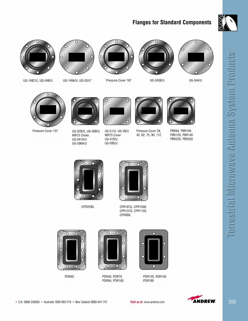
• U.K. 0800-250055 • Australia 1800-803 219 • New Zealand 0800-441-747 Visit us at: www.andrew.com 205
Flanges for Standard Components
PBR84, PBR100PBR120, PBR140PBR220, PBR320
CPR187G, CPR159GCPR137G, CPR112GCPR90G
UG-148C/U, UG-54B/U UG-149A/U, UG-53/U* UG-343B/UPressure Cover 187
Pressure Cover 137
UG-344/U
UG-52B/U, UG-40B/UWR75 ChokeUG-541A/UUG-596A/U
UG-51/U, UG-39/UWR75 CoverUG-419/UUG-595/U
CPR229G
PDR40 PDR40, PDR70PDR84, PDR100
PDR120, PDR140PDR180
Pressure Cover 28,42, 62, 75, 90, 112
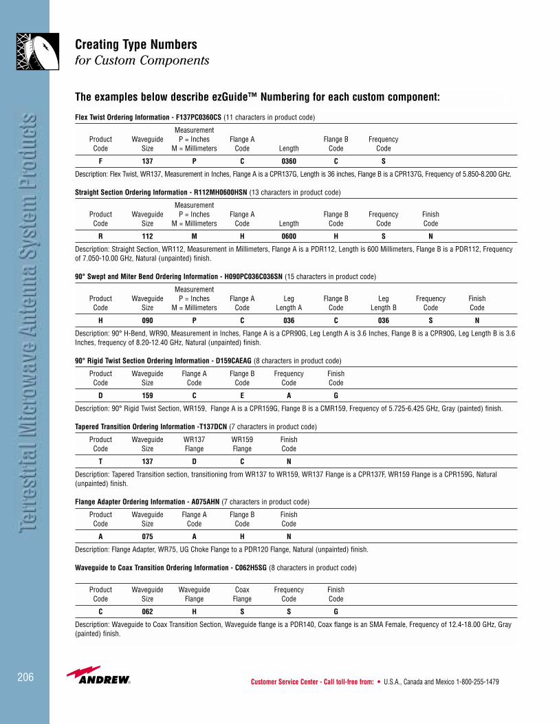
Customer Service Center - Call toll-free from: • U.S.A., Canada and Mexico 1-800-255-1479206
Flex Twist Ordering Information - F137PC0360CS (11 characters in product code)
MeasurementProduct Waveguide P = Inches Flange A Flange B Frequency
Code Size M = Millimeters Code Length Code Code
F 137 P C 0360 C S
Description: Flex Twist, WR137, Measurement in Inches, Flange A is a CPR137G, Length is 36 inches, Flange B is a CPR137G, Frequency of 5.850-8.200 GHz.
Straight Section Ordering Information - R112MH0600HSN (13 characters in product code)
MeasurementProduct Waveguide P = Inches Flange A Flange B Frequency Finish
Code Size M = Millimeters Code Length Code Code Code
R 112 M H 0600 H S N
Description: Straight Section, WR112, Measurement in Millimeters, Flange A is a PDR112, Length is 600 Millimeters, Flange B is a PDR112, Frequencyof 7.050-10.00 GHz, Natural (unpainted) finish.
90° Swept and Miter Bend Ordering Information - H090PC036C036SN (15 characters in product code)
MeasurementProduct Waveguide P = Inches Flange A Leg Flange B Leg Frequency Finish
Code Size M = Millimeters Code Length A Code Length B Code Code
H 090 P C 036 C 036 S N
Description: 90° H-Bend, WR90, Measurement in Inches, Flange A is a CPR90G, Leg Length A is 3.6 Inches, Flange B is a CPR90G, Leg Length B is 3.6Inches, frequency of 8.20-12.40 GHz, Natural (unpainted) finish.
90° Rigid Twist Section Ordering Information - D159CAEAG (8 characters in product code)
Product Waveguide Flange A Flange B Frequency FinishCode Size Code Code Code Code
D 159 C E A G
Description: 90° Rigid Twist Section, WR159, Flange A is a CPR159G, Flange B is a CMR159, Frequency of 5.725-6.425 GHz, Gray (painted) finish.
Tapered Transition Ordering Information -T137DCN (7 characters in product code)
Product Waveguide WR137 WR159 FinishCode Size Flange Flange Code
T 137 D C N
Description: Tapered Transition section, transitioning from WR137 to WR159, WR137 Flange is a CPR137F, WR159 Flange is a CPR159G, Natural(unpainted) finish.
Flange Adapter Ordering Information - A075AHN (7 characters in product code)
Product Waveguide Flange A Flange B FinishCode Size Code Code Code
A 075 A H N
Description: Flange Adapter, WR75, UG Choke Flange to a PDR120 Flange, Natural (unpainted) finish.
Waveguide to Coax Transition Ordering Information - C062H5SG (8 characters in product code)
Product Waveguide Waveguide Coax Frequency FinishCode Size Flange Flange Code Code
C 062 H S S G
Description: Waveguide to Coax Transition Section, Waveguide flange is a PDR140, Coax flange is an SMA Female, Frequency of 12.4-18.00 GHz, Gray(painted) finish.
Creating Type Numbers for Custom Components
The examples below describe ezGuide™ Numbering for each custom component:
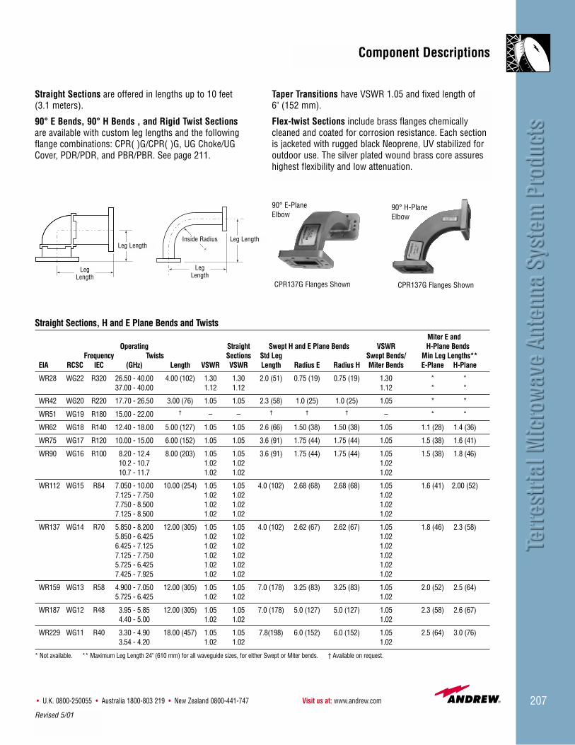
• U.K. 0800-250055 • Australia 1800-803 219 • New Zealand 0800-441-747 Visit us at: www.andrew.com 207
Straight Sections, H and E Plane Bends and TwistsMiter E and
Operating Straight Swept H and E Plane Bends VSWR H-Plane Bends Frequency Twists Sections Std Leg Swept Bends/ Min Leg Lengths**
EIA RCSC IEC (GHz) Length VSWR VSWR Length Radius E Radius H Miter Bends E-Plane H-Plane
WR28 WG22 R320 26.50 - 40.00 4.00 (102) 1.30 1.30 2.0 (51) 0.75 (19) 0.75 (19) 1.30 * *37.00 - 40.00 1.12 1.12 1.12 * *
WR42 WG20 R220 17.70 - 26.50 3.00 (76) 1.05 1.05 2.3 (58) 1.0 (25) 1.0 (25) 1.05 * *
WR51 WG19 R180 15.00 - 22.00 † – – † † † – * *
WR62 WG18 R140 12.40 - 18.00 5.00 (127) 1.05 1.05 2.6 (66) 1.50 (38) 1.50 (38) 1.05 1.1 (28) 1.4 (36)
WR75 WG17 R120 10.00 - 15.00 6.00 (152) 1.05 1.05 3.6 (91) 1.75 (44) 1.75 (44) 1.05 1.5 (38) 1.6 (41)
WR90 WG16 R100 8.20 - 12.4 8.00 (203) 1.05 1.05 3.6 (91) 1.75 (44) 1.75 (44) 1.05 1.5 (38) 1.8 (46)10.2 - 10.7 1.02 1.02 1.0210.7 - 11.7 1.02 1.02 1.02
WR112 WG15 R84 7.050 - 10.00 10.00 (254) 1.05 1.05 4.0 (102) 2.68 (68) 2.68 (68) 1.05 1.6 (41) 2.00 (52)7.125 - 7.750 1.02 1.02 1.027.750 - 8.500 1.02 1.02 1.027.125 - 8.500 1.02 1.02 1.02
WR137 WG14 R70 5.850 - 8.200 12.00 (305) 1.05 1.05 4.0 (102) 2.62 (67) 2.62 (67) 1.05 1.8 (46) 2.3 (58)5.850 - 6.425 1.02 1.02 1.026.425 - 7.125 1.02 1.02 1.027.125 - 7.750 1.02 1.02 1.025.725 - 6.425 1.02 1.02 1.027.425 - 7.925 1.02 1.02 1.02
WR159 WG13 R58 4.900 - 7.050 12.00 (305) 1.05 1.05 7.0 (178) 3.25 (83) 3.25 (83) 1.05 2.0 (52) 2.5 (64)5.725 - 6.425 1.02 1.02 1.02
WR187 WG12 R48 3.95 - 5.85 12.00 (305) 1.05 1.05 7.0 (178) 5.0 (127) 5.0 (127) 1.05 2.3 (58) 2.6 (67)4.40 - 5.00 1.02 1.02 1.02
WR229 WG11 R40 3.30 - 4.90 18.00 (457) 1.05 1.05 7.8(198) 6.0 (152) 6.0 (152) 1.05 2.5 (64) 3.0 (76)3.54 - 4.20 1.02 1.02 1.02
* Not available. ** Maximum Leg Length 24" (610 mm) for all waveguide sizes, for either Swept or Miter bends. † Available on request.
Straight Sections are offered in lengths up to 10 feet (3.1 meters).
90° E Bends, 90° H Bends , and Rigid Twist Sectionsare available with custom leg lengths and the followingflange combinations: CPR( )G/CPR( )G, UG Choke/UGCover, PDR/PDR, and PBR/PBR. See page 211.
Component Descriptions
Taper Transitions have VSWR 1.05 and fixed length of 6" (152 mm).
Flex-twist Sections include brass flanges chemicallycleaned and coated for corrosion resistance. Each sectionis jacketed with rugged black Neoprene, UV stabilized foroutdoor use. The silver plated wound brass core assureshighest flexibility and low attenuation.
90° E-PlaneElbow
CPR137G Flanges Shown CPR137G Flanges Shown
Leg Length
90° H-PlaneElbow
Leg Length
LegLength
LegLength
Inside Radius
Revised 5/01
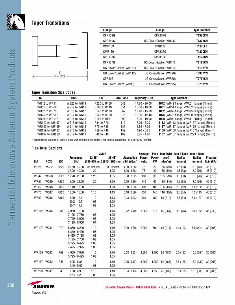
Customer Service Center - Call toll-free from: • U.S.A., Canada and Mexico 1-800-255-1479208
Taper Transition Size CodesEIA RCSC IEC Size Code Frequency (GHz) Type Number*
WR42 to WR51 WG20 to WG19 R220 to R180 042 17.70 - 20.00 T042 (WR42 flange) (WR51 flange) (Finish)WR51 to WR62 WG19 to WG18 R180 to R140 051 15.00 - 18.00 T051 (WR51 flange) (WR62 flange) (Finish)WR62 to WR75 WG18 to WG17 R140 to R120 062 12.40 - 15.00 T062 (WR62 flange) (WR75 flange) (Finish)WR75 to WR90 WG17 to WG16 R120 to R100 075 10.00 - 12.40 T075 (WR75 flange) (WR90 flange) (Finish)WR90 to WR112 WG16 to WG15 R100 to R84 090 8.20 - 10.00 T090 (WR90 flange) (WR112 flange) (Finish)WR112 to WR137 WG15 to WG14 R84 to R70 112 7.05 - 8.20 T112 (WR112 flange) (WR137 flange) (Finish)WR137 to WR159 WG14 to WG13 R70 to R58 137 5.85 - 7.05 T137 (WR137 flange) (WR159 flange) (Finish)WR159 to WR187 WG13 to WG12 R58 to R48 159 4.90 - 5.85 T159 (WR159 flange) (WR187flange) (Finish)WR187 to WR229 WG12 to WG11 R48 to R40 187 3.95 - 4.90 T187 (WR187 flange) (WR229 flange) (Finish)
* Insert flange code from Table 3, page 204 and the finish code: N for Natural (unpainted) or G for Gray (painted)
Flange Flange Type Number
CPR159G CPR137G T137CCN
CPR159G UG Cover/Gasket (WR137) T137YCN
CMR159 CMR137 T137EEN
CMR159 CPR137G T137CEN
CPR137G CPR112G T112CCN
CPR137G UG Cover/Gasket (WR112) T112YCN
UG Cover/Gasket (WR137) UG Cover/Gasket (WR112) T112YYN
UG Cover/Gasket (WR112) UG Cover/Gasket (WR90) T090YYN
CPR90G UG Cover/Gasket (WR75) T075YCN
UG Cover/Gasket (WR90) UG Cover/Gasket (WR75) T075YYN
6"(152 mm)
Flex-Twist SectionsVSWR Average Peak Max Twist Min E-Bend Min H-Bend
Frequency 12-36" 36-48" Attenuation Power Power deg/ft Radius Radius PressureEIA RCSC IEC (GHz) (300-915 mm) (915-1200 mm) dB/ft (dB/m) watts kW (deg/m) in (mm) in (mm) lb/in (kPa)
WR28 WG22 R320 26.50 - 40.00 On Request On Request 1.00 (3.28) 75 20 155 (510) 1.5 (38) 3.0 (76) 45 (310)37.00 - 40.00 1.20 1.25 1.00 (3.28) 75 20 155 (510) 1.5 (38) 3.0 (76) 45 (310)
WR42 WG20 R220 17.70 - 26.50 1.25 1.35 0.80 (2.62) 100 39 155 (510) 1.5 (38) 3.0 (76) 45 (310)
WR51 WG19 R180 15.00 - 22.00 1.20 1.20 0.55 (1.80) 140 60 135 (445) 1.5 (38) 3.0 (76) 45 (310)
WR62 WG18 R140 12.40 - 18.00 1.10 1.20 0.30 (0.99) 400 100 135 (445) 2.0 (52) 4.0 (102) 45 (310)
WR75 WG17 R120 10.00 - 15.00 1.10 1.13 0.18 (0.59) 750 140 110 (360) 2.5 (64) 4.5 (115) 45 (310)
WR90 WG16 R100 8.20 - 12.4 1.10 1.13 0.13 (0.43) 960 180 95 (310) 2.5 (64) 5.0 (127) 45 (310)10.2 - 10.7 1.03 1.0510.7 - 11.7 1.03 1.05
WR112 WG15 R84 7.050 - 10.00 1.10 1.13 0.12 (0.40) 1,260 315 80 (264) 3.0 (76) 6.0 (152) 35 (240)7.125 - 7.750 1.03 1.057.750 - 8.500 1.03 1.057.125 - 8.500 1.04 1.05
WR137 WG14 R70 5.850 - 8.200 1.10 1.10 0.09 (0.30) 2,000 500 65 (214) 4.0 (102) 8.0 (204) 30 (205)5.850 - 6.425 1.03 1.056.425 - 7.125 1.03 1.057.125 - 7.750 1.03 1.055.725 - 6.425 1.03 1.057.425 - 7.925 1.03 1.05
WR159 WG13 R58 4.900 - 7.050 1.10 1.10 0.08 (2.63) 2,500 1,100 55 (180) 5.0 (127) 10.0 (254) 30 (205)5.725 - 6.425 1.03 1.05
WR187 WG12 R48 3.95 - 5.85 1.10 1.10 0.05 (0.17) 3,000 1,250 50 (165) 6.5 (165) 13.0 (330) 30 (205)4.40 - 5.00 1.03 1.05
WR229 WG11 R40 3.30 - 4.90 1.10 1.10 0.04 (0.13) 4,000 1,550 40 (132) 6.5 (165) 13.0 (330) 30 (205)3.54 - 4.20 1.03 1.05
Taper Transitions
Revised 5/01
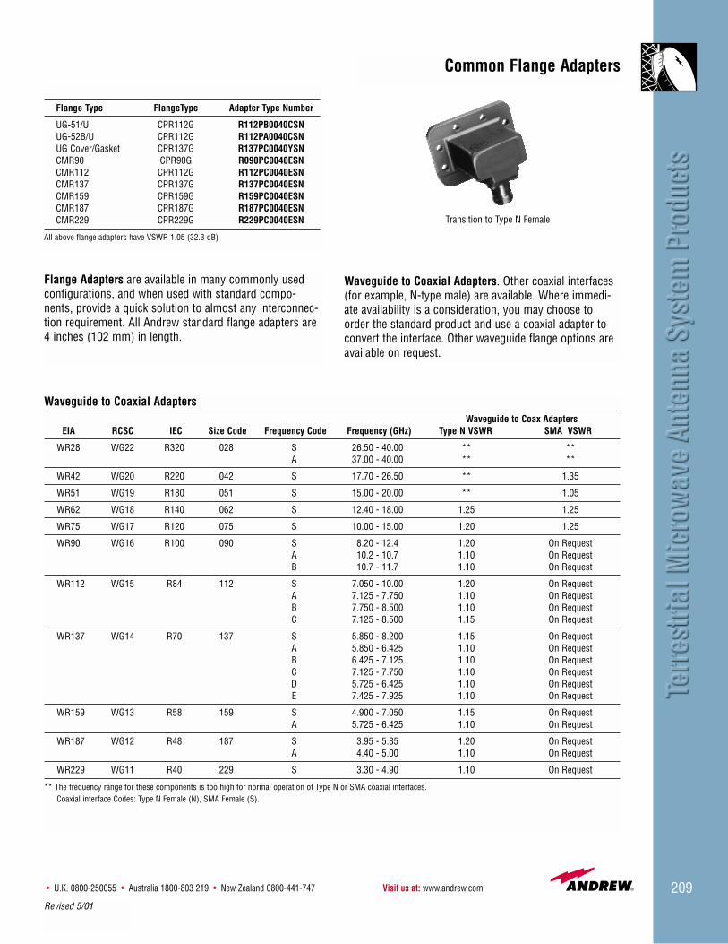
• U.K. 0800-250055 • Australia 1800-803 219 • New Zealand 0800-441-747 Visit us at: www.andrew.com 209
Flange Adapters are available in many commonly usedconfigurations, and when used with standard compo-nents, provide a quick solution to almost any interconnec-tion requirement. All Andrew standard flange adapters are4 inches (102 mm) in length.
Flange Type FlangeType Adapter Type Number
UG-51/U CPR112G R112PB0040CSNUG-52B/U CPR112G R112PA0040CSNUG Cover/Gasket CPR137G R137PC0040YSNCMR90 CPR90G R090PC0040ESNCMR112 CPR112G R112PC0040ESNCMR137 CPR137G R137PC0040ESNCMR159 CPR159G R159PC0040ESNCMR187 CPR187G R187PC0040ESNCMR229 CPR229G R229PC0040ESN
All above flange adapters have VSWR 1.05 (32.3 dB)
Waveguide to Coaxial Adapters. Other coaxial interfaces(for example, N-type male) are available. Where immedi-ate availability is a consideration, you may choose toorder the standard product and use a coaxial adapter toconvert the interface. Other waveguide flange options areavailable on request.
Transition to Type N Female
Common Flange Adapters
Waveguide to Coaxial Adapters Waveguide to Coax Adapters
EIA RCSC IEC Size Code Frequency Code Frequency (GHz) Type N VSWR SMA VSWR
WR28 WG22 R320 028 S 26.50 - 40.00 ** **A 37.00 - 40.00 ** **
WR42 WG20 R220 042 S 17.70 - 26.50 ** 1.35
WR51 WG19 R180 051 S 15.00 - 20.00 ** 1.05
WR62 WG18 R140 062 S 12.40 - 18.00 1.25 1.25
WR75 WG17 R120 075 S 10.00 - 15.00 1.20 1.25
WR90 WG16 R100 090 S 8.20 - 12.4 1.20 On RequestA 10.2 - 10.7 1.10 On RequestB 10.7 - 11.7 1.10 On Request
WR112 WG15 R84 112 S 7.050 - 10.00 1.20 On RequestA 7.125 - 7.750 1.10 On RequestB 7.750 - 8.500 1.10 On RequestC 7.125 - 8.500 1.15 On Request
WR137 WG14 R70 137 S 5.850 - 8.200 1.15 On RequestA 5.850 - 6.425 1.10 On RequestB 6.425 - 7.125 1.10 On RequestC 7.125 - 7.750 1.10 On RequestD 5.725 - 6.425 1.10 On RequestE 7.425 - 7.925 1.10 On Request
WR159 WG13 R58 159 S 4.900 - 7.050 1.15 On RequestA 5.725 - 6.425 1.10 On Request
WR187 WG12 R48 187 S 3.95 - 5.85 1.20 On RequestA 4.40 - 5.00 1.10 On Request
WR229 WG11 R40 229 S 3.30 - 4.90 1.10 On Request
** The frequency range for these components is too high for normal operation of Type N or SMA coaxial interfaces.Coaxial interface Codes: Type N Female (N), SMA Female (S).
Revised 5/01
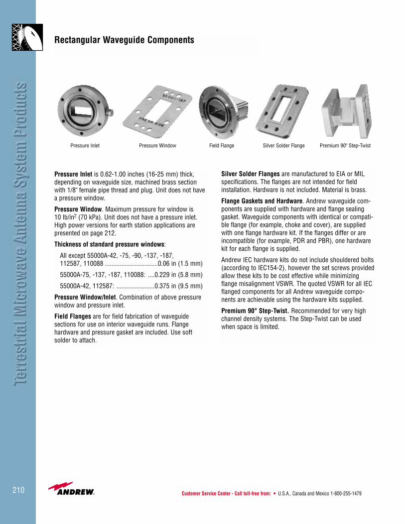
Customer Service Center - Call toll-free from: • U.S.A., Canada and Mexico 1-800-255-1479210
Pressure Inlet is 0.62-1.00 inches (16-25 mm) thick, depending on waveguide size, machined brass section with 1/8" female pipe thread and plug. Unit does not havea pressure window.
Pressure Window. Maximum pressure for window is 10 lb/in2 (70 kPa). Unit does not have a pressure inlet.High power versions for earth station applications are presented on page 212.
Thickness of standard pressure windows:
All except 55000A-42, -75, -90, -137, -187, 112587, 110088 ................................0.06 in (1.5 mm)
55000A-75, -137, -187, 110088: ....0.229 in (5.8 mm)
55000A-42, 112587: .......................0.375 in (9.5 mm)
Pressure Window/Inlet. Combination of above pressurewindow and pressure inlet.
Field Flanges are for field fabrication of waveguide sections for use on interior waveguide runs. Flange hardware and pressure gasket are included. Use soft solder to attach.
Pressure Inlet Pressure Window Field Flange Silver Solder Flange Premium 90º Step-Twist
Silver Solder Flanges are manufactured to EIA or MILspecifications. The flanges are not intended for fieldinstallation. Hardware is not included. Material is brass.
Flange Gaskets and Hardware. Andrew waveguide com-ponents are supplied with hardware and flange sealinggasket. Waveguide components with identical or compati-ble flange (for example, choke and cover), are suppliedwith one flange hardware kit. If the flanges differ or areincompatible (for example, PDR and PBR), one hardwarekit for each flange is supplied.
Andrew IEC hardware kits do not include shouldered bolts(according to IEC154-2), however the set screws providedallow these kits to be cost effective while minimizingflange misalignment VSWR. The quoted VSWR for all IECflanged components for all Andrew waveguide compo-nents are achievable using the hardware kits supplied.
Premium 90° Step-Twist. Recommended for very highchannel density systems. The Step-Twist can be usedwhen space is limited.
Rectangular Waveguide Components
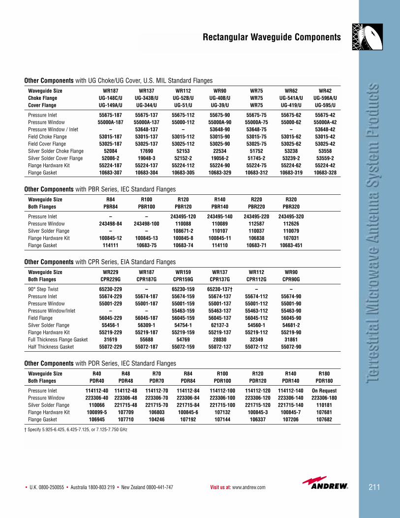
• U.K. 0800-250055 • Australia 1800-803 219 • New Zealand 0800-441-747 Visit us at: www.andrew.com 211
Other Components with UG Choke/UG Cover, U.S. MIL Standard FlangesWaveguide Size WR187 WR137 WR112 WR90 WR75 WR62 WR42Choke Flange UG-148C/U UG-343B/U UG-52B/U UG-40B/U WR75 UG-541A/U UG-596A/UCover Flange UG-149A/U UG-344/U UG-51/U UG-39/U WR75 UG-419/U UG-595/U
Pressure Inlet 55675-187 55675-137 55675-112 55675-90 55675-75 55675-62 55675-42Pressure Window 55000A-187 55000A-137 55000-112 55000A-90 55000A-75 55000-62 55000A-42Pressure Window / Inlet – 53648-137 – 53648-90 53648-75 – 53648-42Field Choke Flange 53015-187 53015-137 53015-112 53015-90 53015-75 53015-62 53015-42Field Cover Flange 53025-187 53025-137 53025-112 53025-90 53025-75 53025-62 53025-42Silver Solder Choke Flange 52084 17690 52153 22534 51752 53238 53558Silver Solder Cover Flange 52086-2 19048-3 52152-2 19056-2 51745-2 53239-2 53559-2Flange Hardware Kit 55224-187 55224-137 55224-112 55224-90 55224-75 55224-62 55224-42Flange Gasket 10683-307 10683-304 10683-305 10683-329 10683-312 10683-319 10683-328
Other Components with PBR Series, IEC Standard FlangesWaveguide Size R84 R100 R120 R140 R220 R320Both Flanges PBR84 PBR100 PBR120 PBR140 PBR220 PBR320
Pressure Inlet – – 243495-120 243495-140 243495-220 243495-320Pressure Window 243498-84 243498-100 110088 110089 112587 112626Silver Solder Flange – – 108671-2 110107 110037 110079Flange Hardware Kit 100845-12 100845-13 100845-8 100845-11 106838 107031Flange Gasket 114111 10683-75 10683-74 114110 10683-71 10683-451
Other Components with CPR Series, EIA Standard FlangesWaveguide Size WR229 WR187 WR159 WR137 WR112 WR90Both Flanges CPR229G CPR187G CPR159G CPR137G CPR112G CPR90G
90° Step Twist 65230-229 – 65230-159 65230-137† – –Pressure Inlet 55674-229 55674-187 55674-159 55674-137 55674-112 55674-90Pressure Window 55001-229 55001-187 55001-159 55001-137 55001-112 55001-90Pressure Window/Inlet – – 55463-159 55463-137 55463-112 55463-90Field Flange 56045-229 56045-187 56045-159 56045-137 56045-112 56045-90Silver Solder Flange 55456-1 56309-1 54754-1 62137-3 54560-1 54681-2Flange Hardware Kit 55219-229 55219-187 55219-159 55219-137 55219-112 55219-90Full Thickness Flange Gasket 31619 55688 54769 28030 32349 31861Half Thickness Gasket 55072-229 55072-187 55072-159 55072-137 55072-112 55072-90
Other Components with PDR Series, IEC Standard FlangesWaveguide Size R40 R48 R70 R84 R100 R120 R140 R180Both Flanges PDR40 PDR48 PDR70 PDR84 PDR100 PDR120 PDR140 PDR180
Pressure Inlet 114112-40 114112-48 114112-70 114112-84 114112-100 114112-120 114112-140 On RequestPressure Window 223306-40 223306-48 223306-70 223306-84 223306-100 223306-120 223306-140 223306-180Silver Solder Flange 110066 221715-48 221715-70 221715-84 221715-100 221715-120 221715-140 110181Flange Hardware Kit 100899-5 107709 106803 100845-6 107132 100845-3 100845-7 107681Flange Gasket 106945 107710 104246 107192 107144 106337 107206 107682
† Specify 5.925-6.425, 6.425-7.125, or 7.125-7.750 GHz
Rectangular Waveguide Components
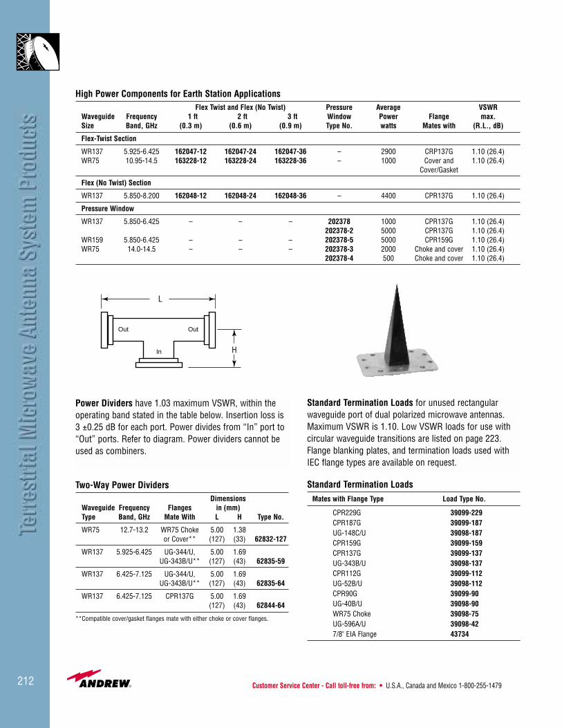
Customer Service Center - Call toll-free from: • U.S.A., Canada and Mexico 1-800-255-1479212
Standard Termination LoadsMates with Flange Type Load Type No.
CPR229G 39099-229CPR187G 39099-187UG-148C/U 39098-187CPR159G 39099-159CPR137G 39099-137UG-343B/U 39098-137CPR112G 39099-112UG-52B/U 39098-112CPR90G 39099-90UG-40B/U 39098-90WR75 Choke 39098-75UG-596A/U 39098-427/8" EIA Flange 43734
Two-Way Power DividersDimensions
Waveguide Frequency Flanges in (mm)Type Band, GHz Mate With L H Type No.
WR75 12.7-13.2 WR75 Choke 5.00 1.38or Cover** (127) (33) 62832-127
WR137 5.925-6.425 UG-344/U, 5.00 1.69UG-343B/U** (127) (43) 62835-59
WR137 6.425-7.125 UG-344/U, 5.00 1.69UG-343B/U** (127) (43) 62835-64
WR137 6.425-7.125 CPR137G 5.00 1.69(127) (43) 62844-64
**Compatible cover/gasket flanges mate with either choke or cover flanges.
High Power Components for Earth Station ApplicationsFlex Twist and Flex (No Twist) Pressure Average VSWR
Waveguide Frequency 1 ft 2 ft 3 ft Window Power Flange max.Size Band, GHz (0.3 m) (0.6 m) (0.9 m) Type No. watts Mates with (R.L., dB)
Flex-Twist Section
WR137 5.925-6.425 162047-12 162047-24 162047-36 – 2900 CRP137G 1.10 (26.4)WR75 10.95-14.5 163228-12 163228-24 163228-36 – 1000 Cover and 1.10 (26.4)
Cover/Gasket
Flex (No Twist) Section
WR137 5.850-8.200 162048-12 162048-24 162048-36 – 4400 CPR137G 1.10 (26.4)
Pressure Window
WR137 5.850-6.425 – – – 202378 1000 CPR137G 1.10 (26.4)202378-2 5000 CPR137G 1.10 (26.4)
WR159 5.850-6.425 – – – 202378-5 5000 CPR159G 1.10 (26.4)WR75 14.0-14.5 – – – 202378-3 2000 Choke and cover 1.10 (26.4)
202378-4 500 Choke and cover 1.10 (26.4)
Power Dividers have 1.03 maximum VSWR, within theoperating band stated in the table below. Insertion loss is3 ±0.25 dB for each port. Power divides from “In” port to“Out” ports. Refer to diagram. Power dividers cannot beused as combiners.
Standard Termination Loads for unused rectangularwaveguide port of dual polarized microwave antennas.Maximum VSWR is 1.10. Low VSWR loads for use withcircular waveguide transitions are listed on page 223.Flange blanking plates, and termination loads used withIEC flange types are available on request.
Out Out
In
L
H
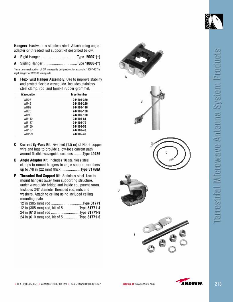
• U.K. 0800-250055 • Australia 1800-803 219 • New Zealand 0800-441-747 Visit us at: www.andrew.com 213
Hangers. Hardware is stainless steel. Attach using angleadapter or threaded rod support kit described below.
A Rigid Hanger ......................................Type 19007-(*)
A Sliding Hanger ...................................Type 19008-(*)*Insert numeral portion of EIA waveguide designation, for example, 19007-137 isrigid hanger for WR137 waveguide.
B Flex-Twist Hanger Assembly. Use to improve stabilityand protect flexible waveguide. Includes stainless steel clamp, rod, and form-it rubber grommet.Waveguide Type Number
WR28 244106-320WR42 244106-220WR62 244106-140WR75 244106-120WR90 244106-100WR112 244106-84WR137 244106-70WR159 244106-58WR187 244106-48WR229 244106-40
C Current By-Pass Kit. Five feet (1.5 m) of No. 6 copperwire and lugs to provide a low-loss current path around flexible waveguide sections .........Type 49486
D Angle Adapter Kit. Includes 10 stainless steel clamps to mount hangers to angle support members up to 7/8 in (22 mm) thick.....................Type 31768A
E Threaded Rod Support Kit. Stainless steel. Use to mount hangers away from supporting structure, under waveguide bridge and inside equipment room. Includes 3/8" diameter threaded rod, nuts and washers. Attach to ceiling using included ceiling mounting plate.12 in (305 mm) rod .................................Type 3177112 in (305 mm) rod, kit of 5 .................Type 31771-424 in (610 mm) rod ..............................Type 31771-924 in (610 mm) rod, kit of 5 .................Type 31771-6
A
C
D
E
B
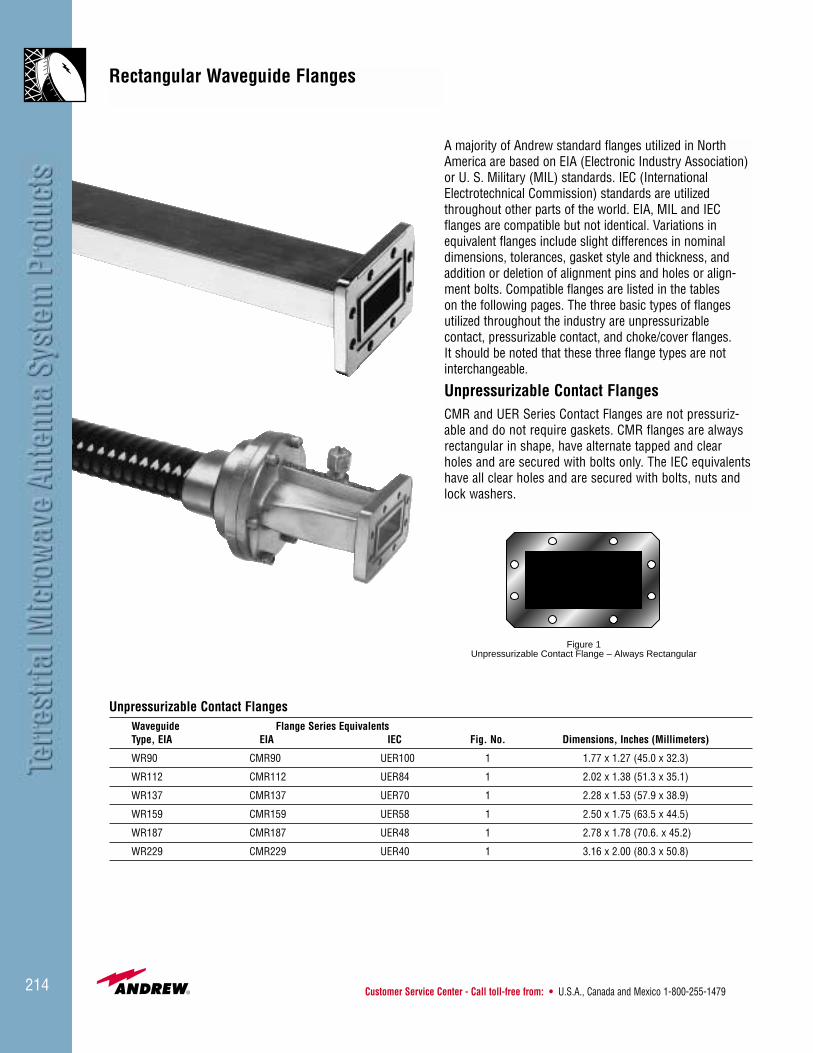
Customer Service Center - Call toll-free from: • U.S.A., Canada and Mexico 1-800-255-1479214
A majority of Andrew standard flanges utilized in NorthAmerica are based on EIA (Electronic Industry Association)or U. S. Military (MIL) standards. IEC (InternationalElectrotechnical Commission) standards are utilizedthroughout other parts of the world. EIA, MIL and IECflanges are compatible but not identical. Variations in equivalent flanges include slight differences in nominaldimensions, tolerances, gasket style and thickness, andaddition or deletion of alignment pins and holes or align-ment bolts. Compatible flanges are listed in the tables on the following pages. The three basic types of flanges utilized throughout the industry are unpressurizable contact, pressurizable contact, and choke/cover flanges. It should be noted that these three flange types are notinterchangeable.
Unpressurizable Contact FlangesCMR and UER Series Contact Flanges are not pressuriz-able and do not require gaskets. CMR flanges are alwaysrectangular in shape, have alternate tapped and clearholes and are secured with bolts only. The IEC equivalentshave all clear holes and are secured with bolts, nuts andlock washers.
Figure 1Unpressurizable Contact Flange – Always Rectangular
Unpressurizable Contact FlangesWaveguide Flange Series EquivalentsType, EIA EIA IEC Fig. No. Dimensions, Inches (Millimeters)
WR90 CMR90 UER100 1 1.77 x 1.27 (45.0 x 32.3)
WR112 CMR112 UER84 1 2.02 x 1.38 (51.3 x 35.1)
WR137 CMR137 UER70 1 2.28 x 1.53 (57.9 x 38.9)
WR159 CMR159 UER58 1 2.50 x 1.75 (63.5 x 44.5)
WR187 CMR187 UER48 1 2.78 x 1.78 (70.6. x 45.2)
WR229 CMR229 UER40 1 3.16 x 2.00 (80.3 x 50.8)
Rectangular Waveguide Flanges
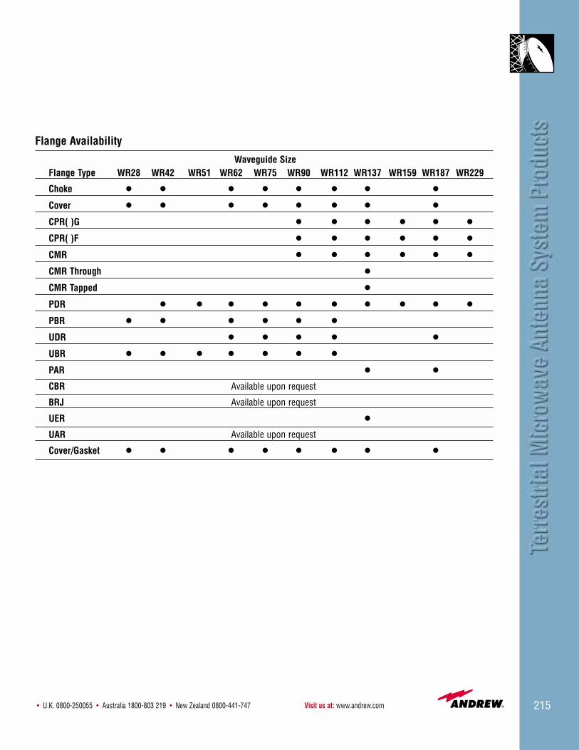
• U.K. 0800-250055 • Australia 1800-803 219 • New Zealand 0800-441-747 Visit us at: www.andrew.com 215
Flange Availability
Waveguide SizeFlange Type WR28 WR42 WR51 WR62 WR75 WR90 WR112 WR137 WR159 WR187 WR229
Choke • • • • • • • •Cover • • • • • • • •CPR( )G • • • • • •CPR( )F • • • • • •CMR • • • • • •CMR Through •CMR Tapped •PDR • • • • • • • • • •PBR • • • • • •UDR • • • • •UBR • • • • • • •PAR • •CBR Available upon request
BRJ Available upon request
UER •UAR Available upon request
Cover/Gasket • • • • • • • •
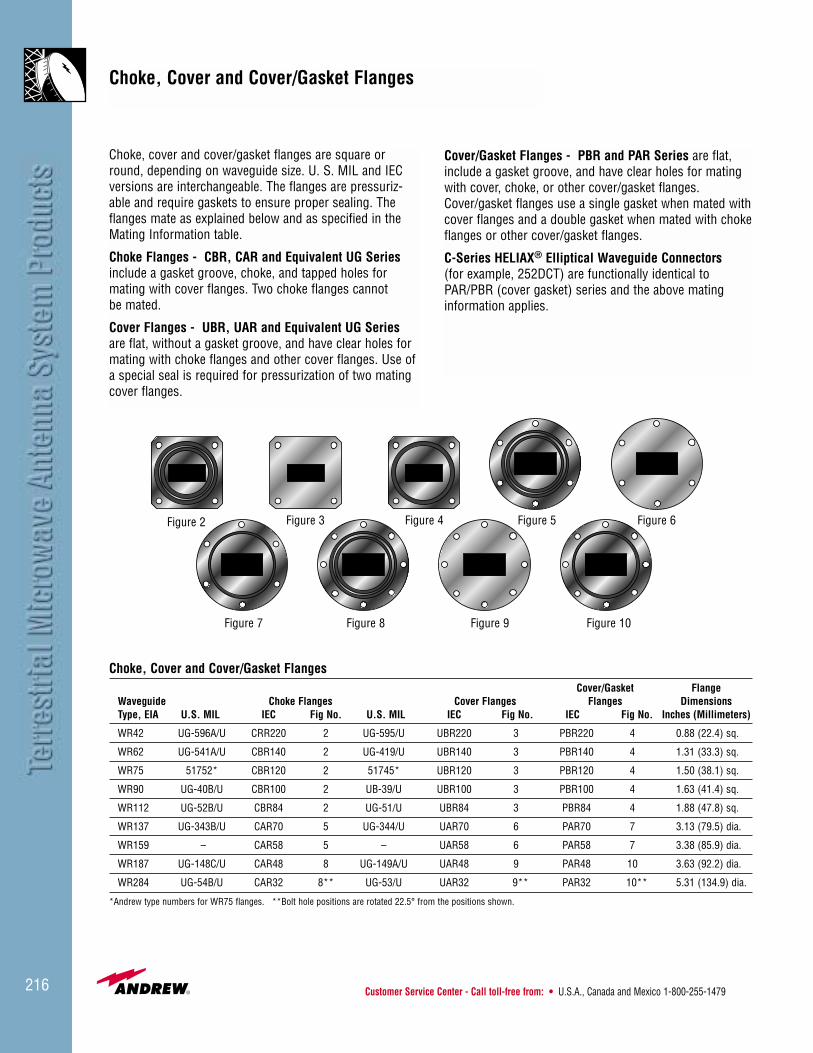
Customer Service Center - Call toll-free from: • U.S.A., Canada and Mexico 1-800-255-1479216
Figure 2 Figure 3 Figure 4 Figure 5
Figure 10Figure 9Figure 8Figure 7
Figure 6
Choke, cover and cover/gasket flanges are square orround, depending on waveguide size. U. S. MIL and IECversions are interchangeable. The flanges are pressuriz-able and require gaskets to ensure proper sealing. Theflanges mate as explained below and as specified in theMating Information table.
Choke Flanges - CBR, CAR and Equivalent UG Seriesinclude a gasket groove, choke, and tapped holes for mating with cover flanges. Two choke flanges cannot be mated.
Cover Flanges - UBR, UAR and Equivalent UG Seriesare flat, without a gasket groove, and have clear holes formating with choke flanges and other cover flanges. Use ofa special seal is required for pressurization of two matingcover flanges.
Choke, Cover and Cover/Gasket FlangesCover/Gasket Flange
Waveguide Choke Flanges Cover Flanges Flanges DimensionsType, EIA U.S. MIL IEC Fig No. U.S. MIL IEC Fig No. IEC Fig No. Inches (Millimeters)
WR42 UG-596A/U CRR220 2 UG-595/U UBR220 3 PBR220 4 0.88 (22.4) sq.
WR62 UG-541A/U CBR140 2 UG-419/U UBR140 3 PBR140 4 1.31 (33.3) sq.
WR75 51752* CBR120 2 51745* UBR120 3 PBR120 4 1.50 (38.1) sq.
WR90 UG-40B/U CBR100 2 UB-39/U UBR100 3 PBR100 4 1.63 (41.4) sq.
WR112 UG-52B/U CBR84 2 UG-51/U UBR84 3 PBR84 4 1.88 (47.8) sq.
WR137 UG-343B/U CAR70 5 UG-344/U UAR70 6 PAR70 7 3.13 (79.5) dia.
WR159 – CAR58 5 – UAR58 6 PAR58 7 3.38 (85.9) dia.
WR187 UG-148C/U CAR48 8 UG-149A/U UAR48 9 PAR48 10 3.63 (92.2) dia.
WR284 UG-54B/U CAR32 8** UG-53/U UAR32 9** PAR32 10** 5.31 (134.9) dia.
*Andrew type numbers for WR75 flanges. **Bolt hole positions are rotated 22.5° from the positions shown.
Cover/Gasket Flanges - PBR and PAR Series are flat,include a gasket groove, and have clear holes for matingwith cover, choke, or other cover/gasket flanges.Cover/gasket flanges use a single gasket when mated withcover flanges and a double gasket when mated with chokeflanges or other cover/gasket flanges.
C-Series HELIAX® Elliptical Waveguide Connectors(for example, 252DCT) are functionally identical toPAR/PBR (cover gasket) series and the above matinginformation applies.
Figure 2 Figure 3 Figure 4 Figure 5 Figure 6
Figure 10Figure 9Figure 8Figure 7
Choke, Cover and Cover/Gasket Flanges
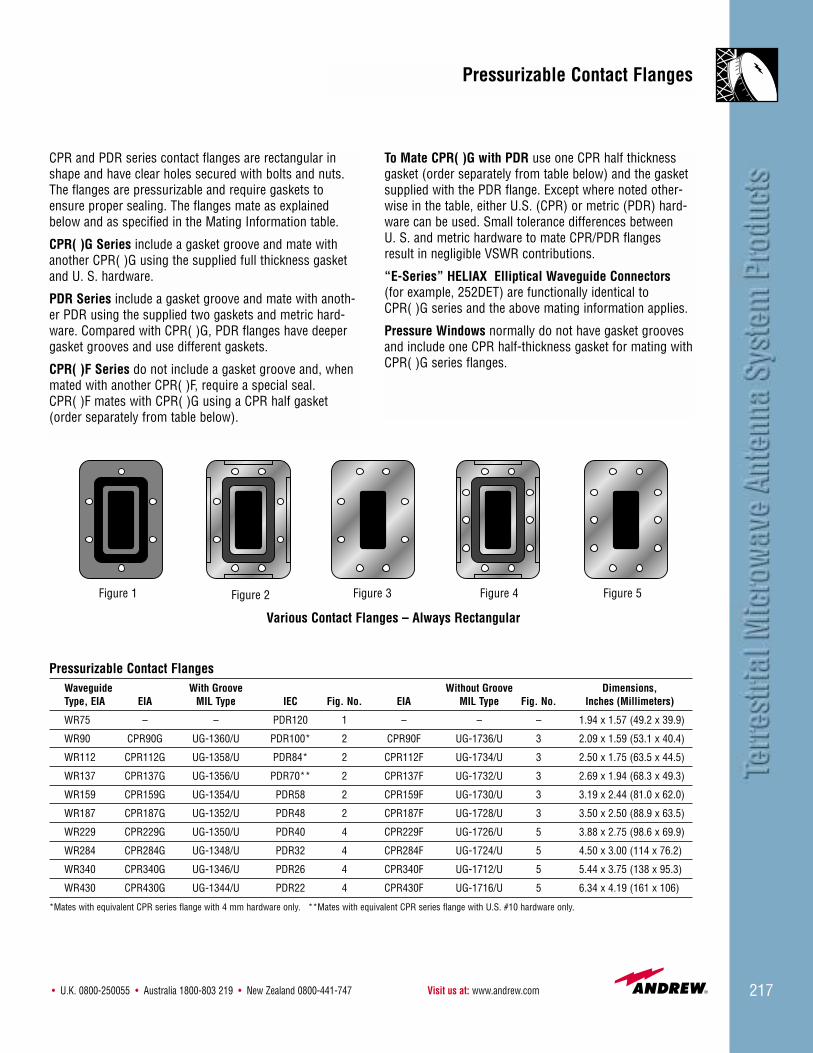
• U.K. 0800-250055 • Australia 1800-803 219 • New Zealand 0800-441-747 Visit us at: www.andrew.com 217
CPR and PDR series contact flanges are rectangular inshape and have clear holes secured with bolts and nuts.The flanges are pressurizable and require gaskets toensure proper sealing. The flanges mate as explainedbelow and as specified in the Mating Information table.
CPR( )G Series include a gasket groove and mate withanother CPR( )G using the supplied full thickness gasketand U. S. hardware.
PDR Series include a gasket groove and mate with anoth-er PDR using the supplied two gaskets and metric hard-ware. Compared with CPR( )G, PDR flanges have deepergasket grooves and use different gaskets.
CPR( )F Series do not include a gasket groove and, whenmated with another CPR( )F, require a special seal. CPR( )F mates with CPR( )G using a CPR half gasket(order separately from table below).
To Mate CPR( )G with PDR use one CPR half thicknessgasket (order separately from table below) and the gasketsupplied with the PDR flange. Except where noted other-wise in the table, either U.S. (CPR) or metric (PDR) hard-ware can be used. Small tolerance differences between U. S. and metric hardware to mate CPR/PDR flangesresult in negligible VSWR contributions.
“E-Series” HELIAX Elliptical Waveguide Connectors(for example, 252DET) are functionally identical to CPR( )G series and the above mating information applies.
Pressure Windows normally do not have gasket groovesand include one CPR half-thickness gasket for mating withCPR( )G series flanges.
Pressurizable Contact FlangesWaveguide With Groove Without Groove Dimensions,Type, EIA EIA MIL Type IEC Fig. No. EIA MIL Type Fig. No. Inches (Millimeters)
WR75 – – PDR120 1 – – – 1.94 x 1.57 (49.2 x 39.9)
WR90 CPR90G UG-1360/U PDR100* 2 CPR90F UG-1736/U 3 2.09 x 1.59 (53.1 x 40.4)
WR112 CPR112G UG-1358/U PDR84* 2 CPR112F UG-1734/U 3 2.50 x 1.75 (63.5 x 44.5)
WR137 CPR137G UG-1356/U PDR70** 2 CPR137F UG-1732/U 3 2.69 x 1.94 (68.3 x 49.3)
WR159 CPR159G UG-1354/U PDR58 2 CPR159F UG-1730/U 3 3.19 x 2.44 (81.0 x 62.0)
WR187 CPR187G UG-1352/U PDR48 2 CPR187F UG-1728/U 3 3.50 x 2.50 (88.9 x 63.5)
WR229 CPR229G UG-1350/U PDR40 4 CPR229F UG-1726/U 5 3.88 x 2.75 (98.6 x 69.9)
WR284 CPR284G UG-1348/U PDR32 4 CPR284F UG-1724/U 5 4.50 x 3.00 (114 x 76.2)
WR340 CPR340G UG-1346/U PDR26 4 CPR340F UG-1712/U 5 5.44 x 3.75 (138 x 95.3)
WR430 CPR430G UG-1344/U PDR22 4 CPR430F UG-1716/U 5 6.34 x 4.19 (161 x 106)
*Mates with equivalent CPR series flange with 4 mm hardware only. **Mates with equivalent CPR series flange with U.S. #10 hardware only.
Various Contact Flanges – Always Rectangular
Fig re 1 Fig re 2 Fig re 3 Fig re 4 Fig re 5Figure 2 Figure 3 Figure 4 Figure 5Figure 1
Pressurizable Contact Flanges
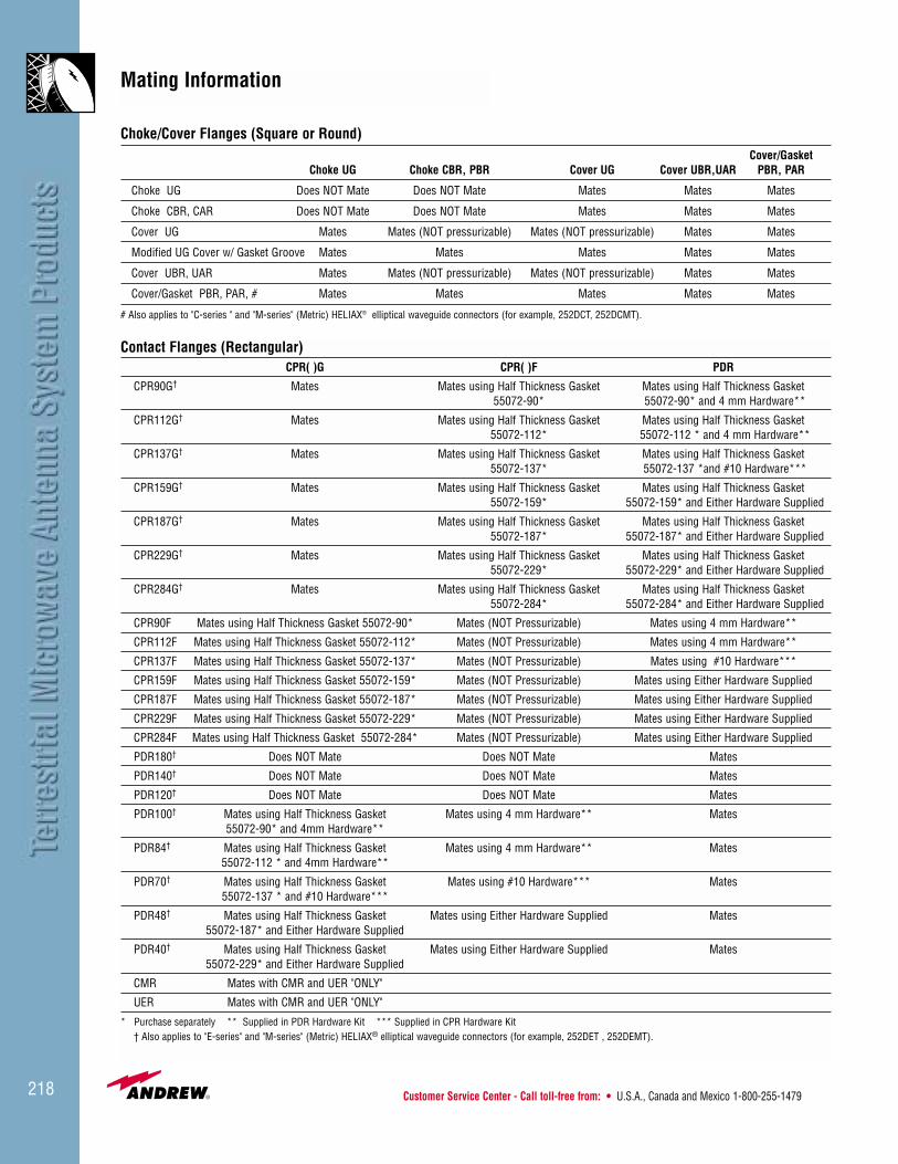
Customer Service Center - Call toll-free from: • U.S.A., Canada and Mexico 1-800-255-1479218
Contact Flanges (Rectangular)CPR( )G CPR( )F PDR
CPR90G† Mates Mates using Half Thickness Gasket Mates using Half Thickness Gasket55072-90* 55072-90* and 4 mm Hardware**
CPR112G† Mates Mates using Half Thickness Gasket Mates using Half Thickness Gasket55072-112* 55072-112 * and 4 mm Hardware**
CPR137G† Mates Mates using Half Thickness Gasket Mates using Half Thickness Gasket55072-137* 55072-137 *and #10 Hardware***
CPR159G† Mates Mates using Half Thickness Gasket Mates using Half Thickness Gasket55072-159* 55072-159* and Either Hardware Supplied
CPR187G† Mates Mates using Half Thickness Gasket Mates using Half Thickness Gasket55072-187* 55072-187* and Either Hardware Supplied
CPR229G† Mates Mates using Half Thickness Gasket Mates using Half Thickness Gasket55072-229* 55072-229* and Either Hardware Supplied
CPR284G† Mates Mates using Half Thickness Gasket Mates using Half Thickness Gasket55072-284* 55072-284* and Either Hardware Supplied
CPR90F Mates using Half Thickness Gasket 55072-90* Mates (NOT Pressurizable) Mates using 4 mm Hardware**
CPR112F Mates using Half Thickness Gasket 55072-112* Mates (NOT Pressurizable) Mates using 4 mm Hardware**
CPR137F Mates using Half Thickness Gasket 55072-137* Mates (NOT Pressurizable) Mates using #10 Hardware***
CPR159F Mates using Half Thickness Gasket 55072-159* Mates (NOT Pressurizable) Mates using Either Hardware Supplied
CPR187F Mates using Half Thickness Gasket 55072-187* Mates (NOT Pressurizable) Mates using Either Hardware Supplied
CPR229F Mates using Half Thickness Gasket 55072-229* Mates (NOT Pressurizable) Mates using Either Hardware Supplied
CPR284F Mates using Half Thickness Gasket 55072-284* Mates (NOT Pressurizable) Mates using Either Hardware Supplied
PDR180† Does NOT Mate Does NOT Mate Mates
PDR140† Does NOT Mate Does NOT Mate Mates
PDR120† Does NOT Mate Does NOT Mate Mates
PDR100† Mates using Half Thickness Gasket Mates using 4 mm Hardware** Mates55072-90* and 4mm Hardware**
PDR84† Mates using Half Thickness Gasket Mates using 4 mm Hardware** Mates55072-112 * and 4mm Hardware**
PDR70† Mates using Half Thickness Gasket Mates using #10 Hardware*** Mates55072-137 * and #10 Hardware***
PDR48† Mates using Half Thickness Gasket Mates using Either Hardware Supplied Mates55072-187* and Either Hardware Supplied
PDR40† Mates using Half Thickness Gasket Mates using Either Hardware Supplied Mates55072-229* and Either Hardware Supplied
CMR Mates with CMR and UER "ONLY"
UER Mates with CMR and UER "ONLY"
* Purchase separately ** Supplied in PDR Hardware Kit *** Supplied in CPR Hardware Kit† Also applies to "E-series" and "M-series" (Metric) HELIAX® elliptical waveguide connectors (for example, 252DET , 252DEMT).
Choke/Cover Flanges (Square or Round)Cover/Gasket
Choke UG Choke CBR, PBR Cover UG Cover UBR,UAR PBR, PAR
Choke UG Does NOT Mate Does NOT Mate Mates Mates Mates
Choke CBR, CAR Does NOT Mate Does NOT Mate Mates Mates Mates
Cover UG Mates Mates (NOT pressurizable) Mates (NOT pressurizable) Mates Mates
Modified UG Cover w/ Gasket Groove Mates Mates Mates Mates Mates
Cover UBR, UAR Mates Mates (NOT pressurizable) Mates (NOT pressurizable) Mates Mates
Cover/Gasket PBR, PAR, # Mates Mates Mates Mates Mates
# Also applies to "C-series " and "M-series" (Metric) HELIAX® elliptical waveguide connectors (for example, 252DCT, 252DCMT).
Mating Information
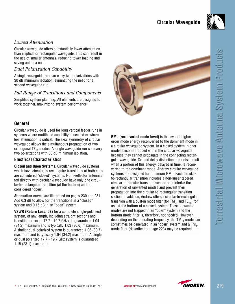
• U.K. 0800-250055 • Australia 1800-803 219 • New Zealand 0800-441-747 Visit us at: www.andrew.com 219
Circular Waveguide
Lowest AttenuationCircular waveguide offers substantially lower attenuationthan elliptical or rectangular waveguide. This can result inthe use of smaller antennas, reducing tower loading andsaving antenna cost.
Dual Polarization CapabilityA single waveguide run can carry two polarizations with30 dB minimum isolation, eliminating the need for a second waveguide run.
Full Range of Transitions and ComponentsSimplifies system planning. All elements are designed towork together, maximizing system performance.
GeneralCircular waveguide is used for long vertical feeder runs insystems where multiband capability is needed or where low attenuation is critical. The axial symmetry of circularwaveguide allows the simultaneous propagation of twoorthogonal TE11 modes. A single waveguide run can carrytwo polarizations with 30 dB minimum isolation.
Electrical CharacteristicsClosed and Open Systems. Circular waveguide systemswhich have circular-to-rectangular transitions at both endsare considered “closed” systems. Horn-reflector antennasfed directly with circular waveguide have only one circu-lar-to-rectangular transition (at the bottom) and are considered “open”.
Attenuation curves are illustrated on pages 230 and 231.Add 0.3 dB to allow for the transitions in a “closed” system and 0.15 dB in an “open” system.
VSWR (Return Loss, dB) for a complete single-polarizedsystem, of any length, including straight sections andtransitions (except 17.7 - 19.7 GHz), is guaranteed 1.04(34.2) maximum and is typically 1.03 (36.6) maximum. A similar dual-polarized system is guaranteed 1.06 (30.7)maximum and is typically 1.04 (34.2) maximum. A singleor dual polarized 17.7 - 19.7 GHz system is guaranteed1.15 (23.1) maximum.
RML (reconverted mode level) is the level of higher order mode energy reconverted to the dominant mode ina circular waveguide system. In a closed system, highermodes become trapped within the circular waveguidebecause they cannot propagate in the connecting rectan-gular waveguide. Ground delay distortion and noise resultwhen a portion of this energy, delayed in time, is recon-verted to the dominant mode. Andrew circular waveguidesystems are designed for minimum RML. Each circular-to-rectangular transition includes a non-linear tapered circular-to-circular transition section to minimize the generation of unwanted modes and prevent their propagation into the circular-to-rectangular transition section. In addition, Andrew offers a circular-to-rectangulartransition with a built-in mode filter (for TM01 and TE21) foruse at the bottom of a closed system. These unwantedmodes are not trapped in an “open” system and the bottom mode filter is, therefore, not needed. However,depending on the operating frequency, the TM11 mode cansometimes be generated in an “open” system and a TM11mode filter (described on page 223) may be required.
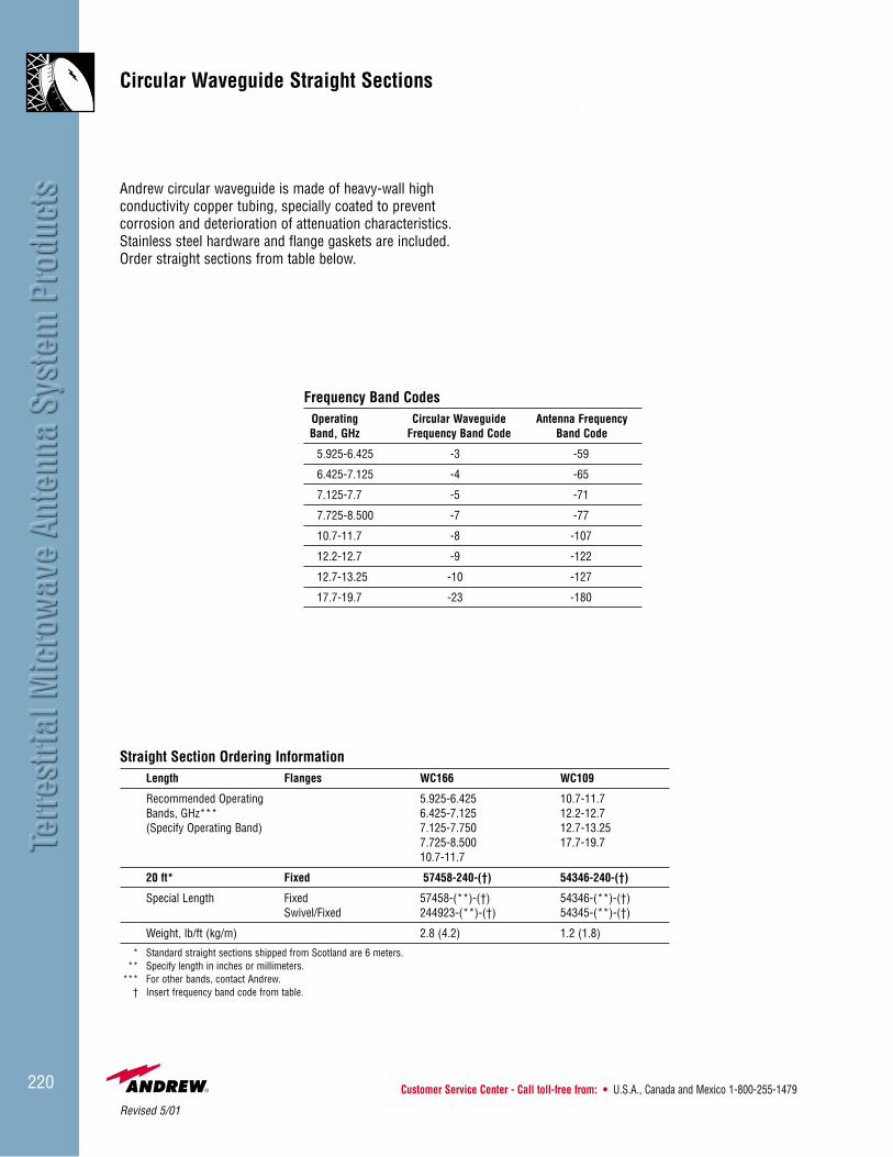
Customer Service Center - Call toll-free from: • U.S.A., Canada and Mexico 1-800-255-1479220
Frequency Band CodesOperating Circular Waveguide Antenna FrequencyBand, GHz Frequency Band Code Band Code
5.925-6.425 -3 -59
6.425-7.125 -4 -65
7.125-7.7 -5 -71
7.725-8.500 -7 -77
10.7-11.7 -8 -107
12.2-12.7 -9 -122
12.7-13.25 -10 -127
17.7-19.7 -23 -180
Straight Section Ordering InformationLength Flanges WC166 WC109
Recommended Operating 5.925-6.425 10.7-11.7Bands, GHz*** 6.425-7.125 12.2-12.7(Specify Operating Band) 7.125-7.750 12.7-13.25
7.725-8.500 17.7-19.710.7-11.7
20 ft* Fixed 57458-240-(†) 54346-240-(†)
Special Length Fixed 57458-(**)-(†) 54346-(**)-(†)Swivel/Fixed 244923-(**)-(†) 54345-(**)-(†)
Weight, lb/ft (kg/m) 2.8 (4.2) 1.2 (1.8)
* Standard straight sections shipped from Scotland are 6 meters.** Specify length in inches or millimeters.
*** For other bands, contact Andrew.† Insert frequency band code from table.
Andrew circular waveguide is made of heavy-wall highconductivity copper tubing, specially coated to preventcorrosion and deterioration of attenuation characteristics.Stainless steel hardware and flange gaskets are included.Order straight sections from table below.
Circular Waveguide Straight Sections
Revised 5/01

• U.K. 0800-250055 • Australia 1800-803 219 • New Zealand 0800-441-747 Visit us at: www.andrew.com 221
Single Polarized** Circular-to-Rectangular Waveguide TransitionsFrequency Rectangular Flange Mates with With Mode Filter No Mode Filter Dimensions, in (mm)Band, GHz EIA or Mil IEC*** (A) (B) V W
WC166
5.925-6.425 CPR137G PDR70 65239-3 58016A-3 18.0 (457) 30.0 (762)6.425-7.125 CPR137G PDR70 65240-1 64157A-1 18.0 (457) 30.0 (762)7.125-7.750 CPR137G PDR70 65322-1 65321A-1 18.0 (457) 30.0 (762)7.725-8500 CPR112G PDR84 65323-3 57459A-3 18.5 (470) 30.5 (775)
WC109
10.700-11.700 CPR90G PDR100 65242-107 57222A-107 13.6 (345) 25.6 (650)12.200-12.700 WR75 Cover/Gasket* – 65242-122 57222A-122 13.8 (351) 25.8 (655)12.700-13.250 WR75 Cover/Gasket* – 67550 67549 13.8 (351) 25.8 (655)
* Andrew “Cover/Gasket” flanges mate with either choke or cover flanges or the corresponding HELIAX® elliptical waveguide connectors.** Not applicable for horn-reflector antenna systems. Use dual polarized transition with one port terminated with load. (page 223)
*** For detailed information on mating flanges refer to pages 214-218.
These transitions convert from circular-to-rectangularwaveguides at one or both ends of the vertical run.Transitions include swivel flanges to simplify installationand polarization alignment. Both rectangular waveguideinputs on dual-polarized transitions enter the circularwaveguide in the same plane†. This simplifies installationand routing. Alignment pins, flange hardware, pressure gaskets, and circular waveguide taper sectionsare included with the transition.
W
Circular-to-Rectangular Waveguide Transitions
ASingle Polarized with
Mode Filter
B
V
Single Polarized withoutMode Filter
“Open” horn-reflector antenna systems use one transitionwithout a mode filter at the bottom of the circular wave-guide run. All other antenna systems use transitions at thetop and bottom of the circular waveguide run. For these, atransition without a mode filter is used at the top and atransition with a mode filter is used at the bottom.† Patented United States 3,924,205; Canada 965,852; United Kingdom 1,394,334;Italy 984,278 and pending in other countries.
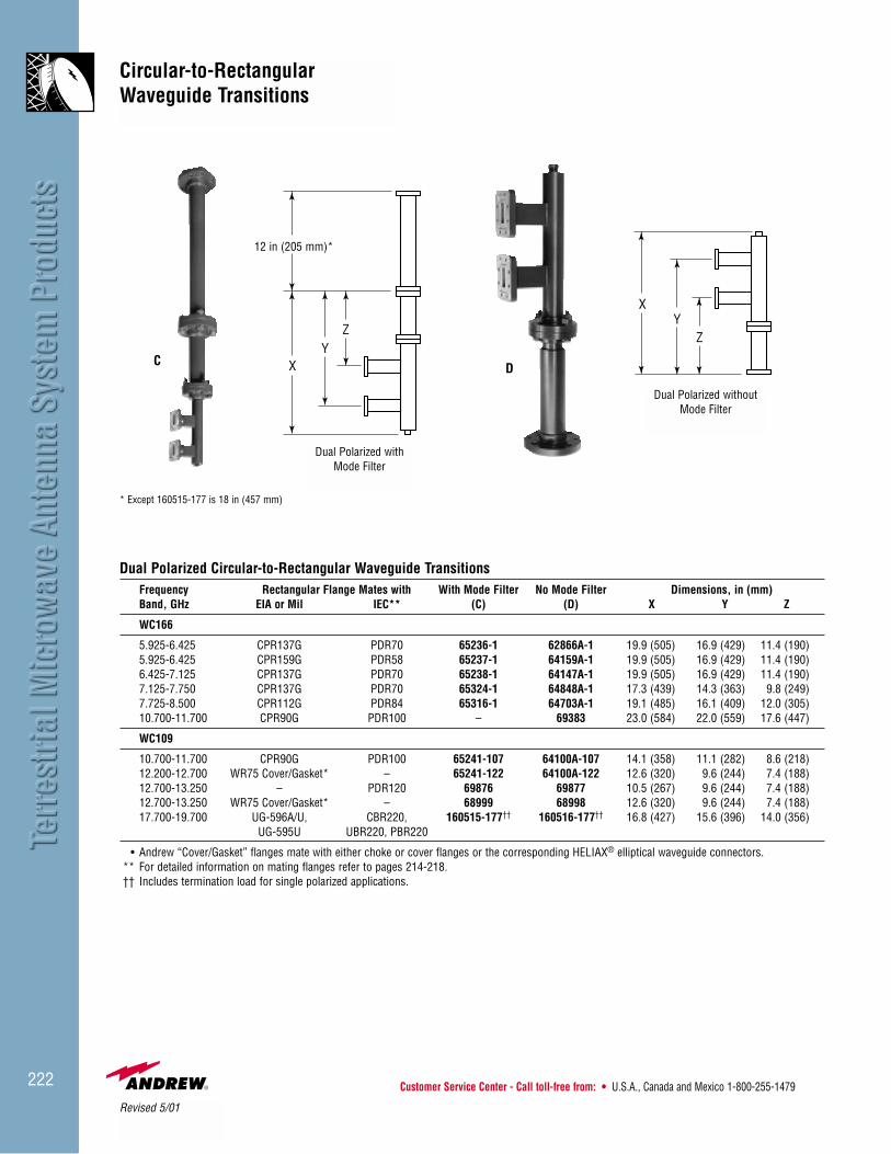
Customer Service Center - Call toll-free from: • U.S.A., Canada and Mexico 1-800-255-1479222
* Except 160515-177 is 18 in (457 mm)
Dual Polarized Circular-to-Rectangular Waveguide TransitionsFrequency Rectangular Flange Mates with With Mode Filter No Mode Filter Dimensions, in (mm)Band, GHz EIA or Mil IEC** (C) (D) X Y Z
WC166
5.925-6.425 CPR137G PDR70 65236-1 62866A-1 19.9 (505) 16.9 (429) 11.4 (190)5.925-6.425 CPR159G PDR58 65237-1 64159A-1 19.9 (505) 16.9 (429) 11.4 (190)6.425-7.125 CPR137G PDR70 65238-1 64147A-1 19.9 (505) 16.9 (429) 11.4 (190)7.125-7.750 CPR137G PDR70 65324-1 64848A-1 17.3 (439) 14.3 (363) 9.8 (249)7.725-8.500 CPR112G PDR84 65316-1 64703A-1 19.1 (485) 16.1 (409) 12.0 (305)10.700-11.700 CPR90G PDR100 – 69383 23.0 (584) 22.0 (559) 17.6 (447)
WC109
10.700-11.700 CPR90G PDR100 65241-107 64100A-107 14.1 (358) 11.1 (282) 8.6 (218)12.200-12.700 WR75 Cover/Gasket* – 65241-122 64100A-122 12.6 (320) 9.6 (244) 7.4 (188)12.700-13.250 – PDR120 69876 69877 10.5 (267) 9.6 (244) 7.4 (188)12.700-13.250 WR75 Cover/Gasket* – 68999 68998 12.6 (320) 9.6 (244) 7.4 (188)17.700-19.700 UG-596A/U, CBR220, 160515-177†† 160516-177†† 16.8 (427) 15.6 (396) 14.0 (356)
UG-595U UBR220, PBR220
• Andrew “Cover/Gasket” flanges mate with either choke or cover flanges or the corresponding HELIAX® elliptical waveguide connectors.** For detailed information on mating flanges refer to pages 214-218.†† Includes termination load for single polarized applications.
C
Circular-to-Rectangular Waveguide Transitions
X
Dual Polarized withMode Filter
Dual Polarized withoutMode Filter
YZ
12 in (205 mm)*
XY
Z
D
Revised 5/01
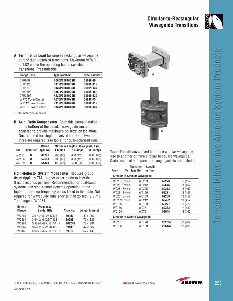
• U.K. 0800-250055 • Australia 1800-803 219 • New Zealand 0800-441-747 Visit us at: www.andrew.com 223
A
A Termination Load for unused rectangular waveguide port of dual-polarized transitions. Maximum VSWR is 1.02 within the operating bands specified for transitions. Pressurizable.Flange Type Type Number* Type Number*
CPR90G R090PC0040CSN 39099-90CPR112G R112PC0040CSN 39099-112CPR137G R137PC0040CSN 39099-137CPR159G R159PC0040CSN 39099-159CPR229G R229PC0040CSN 39099-229WR75 Cover/Gasket R075PY0040YSN 39098-75WR112 Cover/Gasket R112PY0040YSN 39098-112WR137 Cover/Gasket R137PY0040YSN 39098-137
*Order both type numbers
B Axial Ratio Compensator. Rotatable clamp installed at the bottom of the circular waveguide run and adjusted to provide maximum polarization isolation. One required for single-polarized run. One, two, or three are required (see table) for dual-polarized runs.
Clamp Maximum Length of Waveguide, ft (m)For Photo Ref. Type No. 1 Clamp 2 Clamps 3 Clamps
WC281 B 64271 200 (60) 400 (120) 600 (180)WC166 B 57568 200 (60) 400 (120) 600 (180)WC109 B 54348 150 (45) 300 (90) 450 (135)
Horn-Reflector System Mode Filter. Reduces group delay ripple by TM11 higher order mode to less than 3 nanoseconds per hop. Recommended for dual-band systems and single-band systems operating in the higher of the two frequency bands listed in the table. Notrequired for waveguide runs shorter than 25 feet (7.6 m).Top flange is WC281.
Bottom FrequencyFlange Bands, GHz Type No. Length in (mm)
WC281 3.6-4.2, 5.925-6.425 69907 42 (1067)WC281 3.6-4.2, 6.425-7.125 69908 72 (1829)WC281 5.925-6.425, 10.7-11.7 162240 78 (1981)WC269 3.6-4.2, 5.925-6.425 69485 42 (1067)WC166 5.925-6.425, 10.7-11.7 69910 57 (1448)
B
Taper Transitions convert from one circular waveguidesize to another or from circular to square waveguide.Stainless steel hardware and flange gaskets are included.
Transition LengthFrom To Type No. in (mm)
Circular-to-Circular Waveguide
WC281 Swivel WC269 69273 6 (152)WC281 Swivel WC212 49545 18 (457)WC281 Swivel WC205 69272 18 (457)WC281 Swivel WC166 69271 18 (457)WC281 Swivel WC109 69269 18 (457)WC269 Swivel WC212 69492 18 (457)WC166 WC109 69277 11 (279)WC166 WC75 69382 17 (432)WC109 WC75 55648 6 (152)
Circular-to-Square Waveguide
WC281 WS176 202559 30 (762)WC166 WS108 205137 19 (483)
Circular-to-Rectangular Waveguide Transitions
Revised 6/01
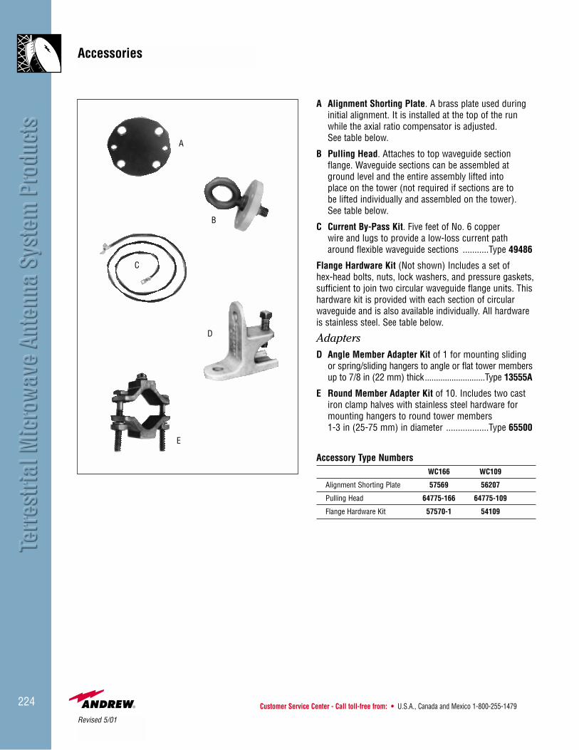
Customer Service Center - Call toll-free from: • U.S.A., Canada and Mexico 1-800-255-1479224
A Alignment Shorting Plate. A brass plate used during initial alignment. It is installed at the top of the run while the axial ratio compensator is adjusted. See table below.
B Pulling Head. Attaches to top waveguide section flange. Waveguide sections can be assembled at ground level and the entire assembly lifted into place on the tower (not required if sections are to be lifted individually and assembled on the tower). See table below.
C Current By-Pass Kit. Five feet of No. 6 copper wire and lugs to provide a low-loss current path around flexible waveguide sections ...........Type 49486
Flange Hardware Kit (Not shown) Includes a set of hex-head bolts, nuts, lock washers, and pressure gaskets,sufficient to join two circular waveguide flange units. Thishardware kit is provided with each section of circularwaveguide and is also available individually. All hardwareis stainless steel. See table below.
AdaptersD Angle Member Adapter Kit of 1 for mounting sliding
or spring/sliding hangers to angle or flat tower members up to 7/8 in (22 mm) thick...........................Type 13555A
E Round Member Adapter Kit of 10. Includes two cast iron clamp halves with stainless steel hardware for mounting hangers to round tower members 1-3 in (25-75 mm) in diameter ..................Type 65500
Accessory Type NumbersWC166 WC109
Alignment Shorting Plate 57569 56207
Pulling Head 64775-166 64775-109
Flange Hardware Kit 57570-1 54109
Accessories
A
B
C
D
E
Revised 5/01
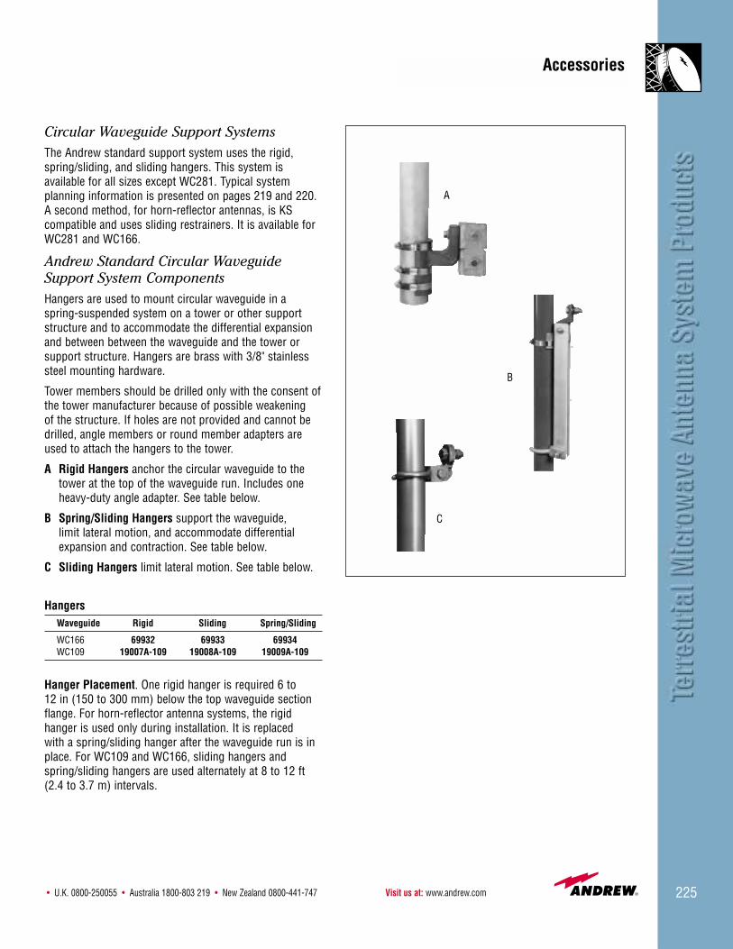
• U.K. 0800-250055 • Australia 1800-803 219 • New Zealand 0800-441-747 Visit us at: www.andrew.com 225
Circular Waveguide Support SystemsThe Andrew standard support system uses the rigid,spring/sliding, and sliding hangers. This system is available for all sizes except WC281. Typical system planning information is presented on pages 219 and 220.A second method, for horn-reflector antennas, is KS compatible and uses sliding restrainers. It is available forWC281 and WC166.
Andrew Standard Circular WaveguideSupport System ComponentsHangers are used to mount circular waveguide in aspring-suspended system on a tower or other supportstructure and to accommodate the differential expansionand between between the waveguide and the tower orsupport structure. Hangers are brass with 3/8" stainlesssteel mounting hardware.
Tower members should be drilled only with the consent ofthe tower manufacturer because of possible weakening of the structure. If holes are not provided and cannot bedrilled, angle members or round member adapters areused to attach the hangers to the tower.
A Rigid Hangers anchor the circular waveguide to the tower at the top of the waveguide run. Includes one heavy-duty angle adapter. See table below.
B Spring/Sliding Hangers support the waveguide, limit lateral motion, and accommodate differential expansion and contraction. See table below.
C Sliding Hangers limit lateral motion. See table below.
HangersWaveguide Rigid Sliding Spring/Sliding
WC166 69932 69933 69934WC109 19007A-109 19008A-109 19009A-109
Hanger Placement. One rigid hanger is required 6 to 12 in (150 to 300 mm) below the top waveguide sectionflange. For horn-reflector antenna systems, the rigid hanger is used only during installation. It is replaced with a spring/sliding hanger after the waveguide run is inplace. For WC109 and WC166, sliding hangers andspring/sliding hangers are used alternately at 8 to 12 ft(2.4 to 3.7 m) intervals.
Accessories
A
B
C
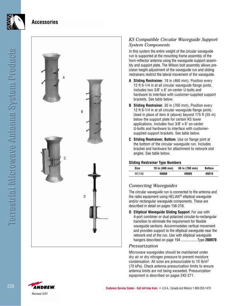
Customer Service Center - Call toll-free from: • U.S.A., Canada and Mexico 1-800-255-1479226
KS Compatible Circular Waveguide SupportSystem ComponentsIn this system the entire weight of the circular waveguiderun is supported at the mounting frame assembly of thehorn-reflector antenna using the waveguide support assem-bly and support plate. The Wilson bolt assembly allows pre-cision height adjustment of the waveguide run and slidingrestrainers restrict the lateral movement of the waveguide.
A Sliding Restrainer, 18 in (460 mm). Position every 12 ft 6-1/4 in at all circular waveguide flange joints. Includes two 3/8" x 6" on-center U-bolts and hardware to interface with customer-supplied supportbrackets. See table below.
B Sliding Restrainer, 30 in (760 mm). Position every 12 ft 6-1/4 in at all circular waveguide flange joints.Used in place of item A (above) beyond 175 ft (55 m)below the support plate for certain KS tower applications. Includes four 3/8" x 6" on-center U-bolts and hardware to interface with customer- supplied support brackets. See table below.
C Sliding Restrainer, Bottom. Use on flange joint at the bottom of the circular waveguide run. Includes bracket and hardware for attachment to network slot angles. See table below.
Sliding Restrainer Type NumbersSize 18 in (460 mm) 30 in (760 mm) Bottom
WC166 49008 49009 49010
Connecting WaveguidesThe circular waveguide run is connected to the antenna andthe radio equipment using HELIAX® elliptical waveguideand/or rectangular waveguide components. These aredescribed in detail on pages 156-218.
D Elliptical Waveguide Sliding Support. For use with 4-port combiner or dual polarized circular-to-rectangular transition to eliminate the requirement for flexible waveguide sections. Accommodates vertical movement and provides support to the elliptical waveguide near the network end of the run. Use with elliptical waveguide hangers described on page 194 ..................Type 200970
PressurizationMicrowave waveguides should be maintained under dry air or dry nitrogen pressure to prevent moisture condensation. All sizes are pressurizable to 10 lb/in2
(70 kPa). Check antenna pressurization limits to ensureantenna limits are not being exceeded. Pressurizationequipment is described on pages 242-271.
Accessories
A
B
C
D
Revised 5/01
• U.K. 0800-250055 • Australia 1800-803 219 • New Zealand 0800-441-747 Visit us at: www.andrew.com 227
dB and dBm
The dB is a logarithmic unit comparing two power levels.
dB = 10 log10
Where P1 is the larger powerIf P1 = 10 watts and P2 = 1 watt, then
dB = 10 log10 10 = 10 dB1
The dBm is a comparison to a reference power of 1 milliwatt (0.001 watt).
dBm = 10 log10
Free Space Propagation Attenuation (Isotropic)
Imperial Units:
Lfs = 96.6 + 20 log10 D + log10 fWhere Lfs= loss in free space in dB
D = path length in milesf = frequency in GHz
Metric Units:Lfs = 92.5 + 20 log10 D + 20 log10 f
Where Lfs = loss in free space in dBD = path length in kilometersf = frequency in GHz
Calculating Receive Signal Level and Antenna Gain
When transmitter power is expressed in dBm and all otherunits are expressed in dB, receive power in dBm can becalculated using the following formula:
Pr = Pt - Lw1 - Lf1 + Ga1 - Lfs + Ga2 - Lw2 - Lf2
Where: Pr = receive power level (dBm)Pt = transmit power (dBm)
Lw = transmission line lossesLf = filter losses
Lfs = free space path lossGa1 = transmit antenna gainGa2 = receive antenna gain
P1
P2
P1
0.001
Calculations
Thus for a 6.175 GHz system with a transmit power of 5 watts (37 dBm) and 200 feet of Type EWP52 HELIAX®
elliptical waveguide (attenuation 1.2 dB/100 feet) at eachend, filter losses of 0.5 dB at each end, and AndrewUHX8-59, UHX8-59 antennas at each end (Mid-band Gain41.3 dB) over a path 30 miles long (Lfs = 141.9 per pre-ceding example).
Pr = 37- 2.4 -.5 + 41.3 - 141.9 + 41.3 - 2.4 - .5 = 28.1dBm
When the minimum receive signal level required to meetperformance objectives (C) is known and the necessaryfade margin (FM) is added, the total antenna gain (Gt)required can be calculated using the following expression:
Gt = Pt - Lw1 - Lf1 - Lfs - Lw2 - Lf2 - FM 96 C
In the above system with a transmit power of 5 watts (37dBm), 200 feet of EWP52 elliptical waveguide (attenuationof 1.2 dB/100 ft) at each end, filter losses of 0.5 dB ateach end, operating over a 30 mile path, assuming areceive signal threshold level requirement (C) of -70 dBmand a desired fade margin of 38 dB, the total antenna gain(Gt) required is:
Gt = 37 - 2.4 - .5 - 141.9 - 2.4 - .5 - 38 - ( -70) = -78.7
To achieve the system performance goal, a negative gain(loss) of 78.76 dB must be made up by the gain of theantennas. If antennas with equal gain are used at eachend of the path, each antenna must then have a gain of 39dB. Andrew UHX8-59 antennas with a mid-band gain of41.3 dB will, therefore, satisfy the requirement.
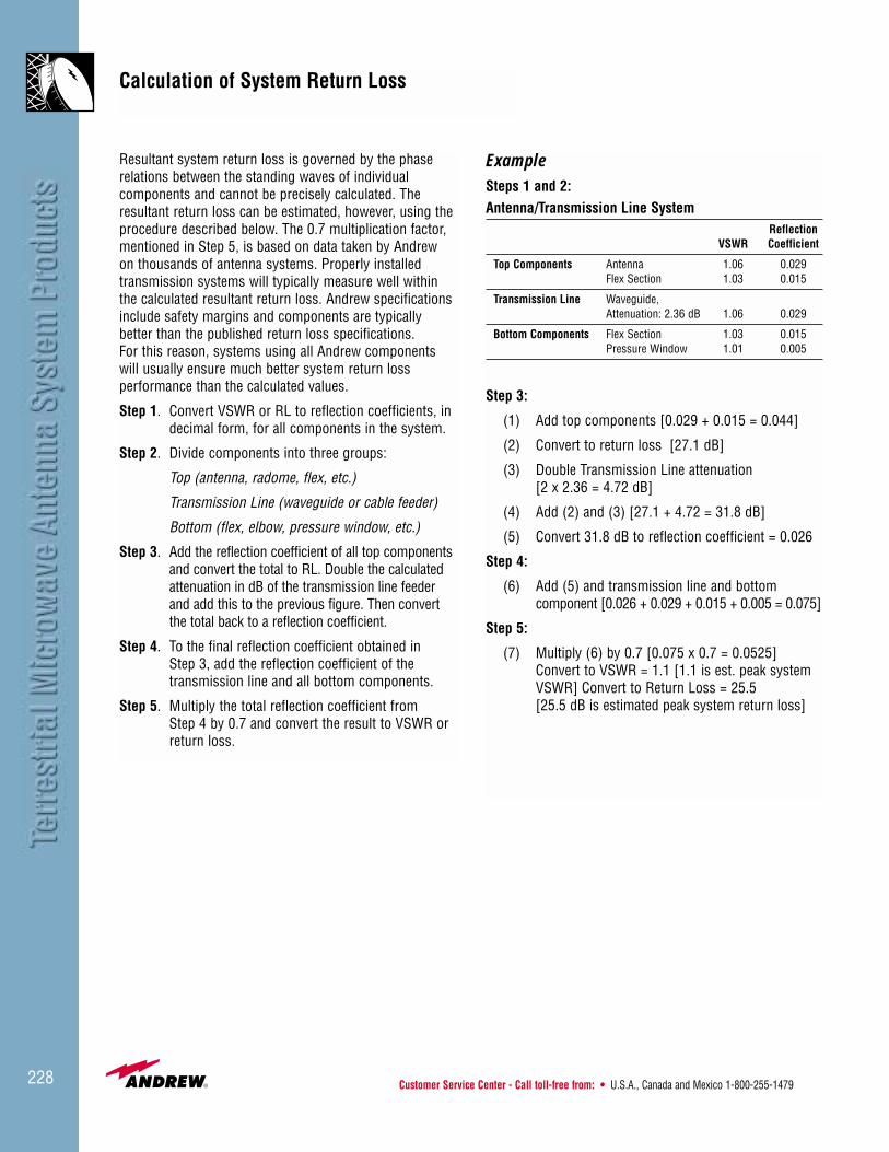
Customer Service Center - Call toll-free from: • U.S.A., Canada and Mexico 1-800-255-1479228
Resultant system return loss is governed by the phaserelations between the standing waves of individual components and cannot be precisely calculated. Theresultant return loss can be estimated, however, using theprocedure described below. The 0.7 multiplication factor,mentioned in Step 5, is based on data taken by Andrew on thousands of antenna systems. Properly installedtransmission systems will typically measure well withinthe calculated resultant return loss. Andrew specificationsinclude safety margins and components are typically better than the published return loss specifications. For this reason, systems using all Andrew componentswill usually ensure much better system return loss performance than the calculated values.
Step 1. Convert VSWR or RL to reflection coefficients, in decimal form, for all components in the system.
Step 2. Divide components into three groups:
Top (antenna, radome, flex, etc.)
Transmission Line (waveguide or cable feeder)
Bottom (flex, elbow, pressure window, etc.)
Step 3. Add the reflection coefficient of all top components and convert the total to RL. Double the calculated attenuation in dB of the transmission line feeder and add this to the previous figure. Then convert the total back to a reflection coefficient.
Step 4. To the final reflection coefficient obtained in Step 3, add the reflection coefficient of the transmission line and all bottom components.
Step 5. Multiply the total reflection coefficient from Step 4 by 0.7 and convert the result to VSWR or return loss.
Calculation of System Return Loss
Example Steps 1 and 2:Antenna/Transmission Line System
ReflectionVSWR Coefficient
Top Components Antenna 1.06 0.029Flex Section 1.03 0.015
Transmission Line Waveguide,Attenuation: 2.36 dB 1.06 0.029
Bottom Components Flex Section 1.03 0.015Pressure Window 1.01 0.005
Step 3:
(1) Add top components [0.029 + 0.015 = 0.044]
(2) Convert to return loss [27.1 dB]
(3) Double Transmission Line attenuation [2 x 2.36 = 4.72 dB]
(4) Add (2) and (3) [27.1 + 4.72 = 31.8 dB]
(5) Convert 31.8 dB to reflection coefficient = 0.026
Step 4:
(6) Add (5) and transmission line and bottom component [0.026 + 0.029 + 0.015 + 0.005 = 0.075]
Step 5:
(7) Multiply (6) by 0.7 [0.075 x 0.7 = 0.0525]Convert to VSWR = 1.1 [1.1 is est. peak system VSWR] Convert to Return Loss = 25.5 [25.5 dB is estimated peak system return loss]
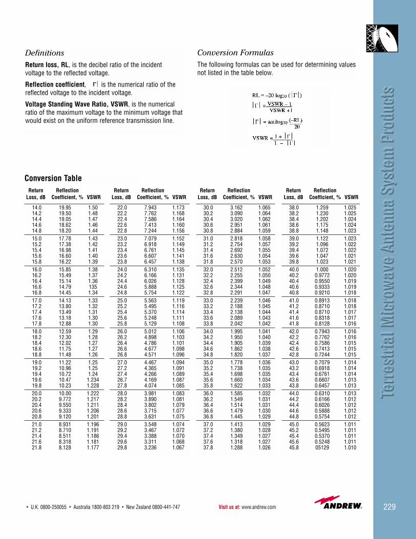
• U.K. 0800-250055 • Australia 1800-803 219 • New Zealand 0800-441-747 Visit us at: www.andrew.com 229
DefinitionsReturn loss, RL, is the decibel ratio of the incident voltage to the reflected voltage.
Reflection coefficient, is the numerical ratio of thereflected voltage to the incident voltage.
Voltage Standing Wave Ratio, VSWR, is the numericalratio of the maximum voltage to the minimum voltage thatwould exist on the uniform reference transmission line.
Conversion TableReturn Reflection
Loss, dB Coefficient, % VSWR
14.0 19.95 1.5014.2 19.50 1.4814.4 19.05 1.4714.6 18.62 1.4614.8 18.20 1.4415.0 17.78 1.4315.2 17.38 1.4215.4 16.98 1.4115.6 16.60 1.4015.8 16.22 1.3916.0 15.85 1.3816.2 15.49 1.3716.4 15.14 1.3616.6 14.79 13516.8 14.45 1.3417.0 14.13 1.3317.2 13.80 1.3217.4 13.49 1.3117.6 13.18 1.3017.8 12.88 1.3018.0 12.59 1.2918.2 12.30 1.2818.4 12.02 1.2718.6 11.75 1.2718.8 11.48 1.2619.0 11.22 1.2519.2 10.96 1.2519.4 10.72 1.2419.6 10.47 1.23419.8 10.23 1.22820.0 10.00 1.22220.2 9.772 1.21720.4 9.550 1.21120.6 9.333 1.20620.8 9.120 1.20121.0 8.931 1.19621.2 8.710 1.19121.4 8.511 1.18621.6 8.318 1.18121.8 8.128 1.177
22.0 7.943 1.17322.2 7.762 1.16822.4 7.586 1.16422.6 7.413 1.16022.8 7.244 1.15623.0 7.079 1.15223.2 6.918 1.14923.4 6.761 1.14523.6 6.607 1.14123.8 6.457 1.13824.0 6.310 1.13524.2 6.166 1.13124.4 6.026 1.12824.6 5.888 1.12524.8 5.754 1.12225.0 5.563 1.11925.2 5.495 1.11625.4 5.370 1.11425.6 5.248 1.11125.8 5.129 1.10826.0 5.012 1.10626.2 4.898 1.10326.4 4.786 1.10126.6 4.677 1.09826.8 4.571 1.09627.0 4.467 1.09427.2 4.365 1.09127.4 4.266 1.08926.7 4.169 1.08727.8 4.074 1.08528.0 3.981 1.08328.2 3.890 1.08128.4 3.802 1.07928.6 3.715 1.07728.8 3.631 1.07529.0 3.548 1.07429.2 3.467 1.07229.4 3.388 1.07029.6 3.311 1.06829.8 3.236 1.067
30.0 3.162 1.06530.2 3.090 1.06430.4 3.020 1.06230.6 2.951 1.06130.8 2.884 1.05931.0 2.818 1.05831.2 2.754 1.05731.4 2.692 1.05531.6 2.630 1.05431.8 2.570 1.05332.0 2.512 1.05232.2 2.255 1.05032.4 2.399 1.04932.6 2.344 1.04832.8 2.291 1.04733.0 2.239 1.04633.2 2.188 1.04533.4 2.138 1.04433.6 2.089 1.04333.8 2.042 1.04234.0 1.995 1.04134.2 1.950 1.04034.4 1.905 1.03934.6 1.862 1.03834.8 1.820 1.03735.0 1.778 1.03635.2 1.738 1.03535.4 1.698 1.03535.6 1.660 1.03435.8 1.622 1.03336.0 1.585 1.03236.2 1.549 1.03136.4 1.514 1.03136.6 1.479 1.03036.8 1.445 1.02937.0 1.413 1.02937.2 1.380 1.02837.4 1.349 1.02737.6 1.318 1.02737.8 1.288 1.026
38.0 1.259 1.02538.2 1.230 1.02538.4 1.202 1.02438.6 1.175 1.02438.8 1.148 1.02339.0 1.122 1.02339.2 1.096 1.02239.4 1.072 1.02239.6 1.047 1.02139.8 1.023 1.02140.0 1.000 1.02040.2 0.9772 1.02040.4 0.9550 1.01940.6 0.9333 1.01940.8 0.9210 1.01841.0 0.8913 1.01841.2 0.8710 1.01841.4 0.8710 1.01741.6 0.8318 1.01741.8 0.8128 1.01642.0 0.7943 1.01642.2 0.7762 1.01642.4 0.7586 1.01542.6 0.7413 1.01542.8 0.7244 1.01543.0 0.7079 1.01443.2 0.6918 1.01443.4 0.6761 1.01443.6 0.6607 1.01343.8 0.6457 1.01344.0 0.6310 1.01344.2 0.6166 1.01244.4 0.6026 1.01244.6 0.5888 1.01244.8 0.5754 1.01245.0 0.5623 1.01145.2 0.5495 1.01145.4 0.5370 1.01145.6 0.5248 1.01145.8 05129 1.010
Return ReflectionLoss, dB Coefficient, % VSWR
Return ReflectionLoss, dB Coefficient, % VSWR
Return ReflectionLoss, dB Coefficient, % VSWR
Conversion FormulasThe following formulas can be used for determining valuesnot listed in the table below.
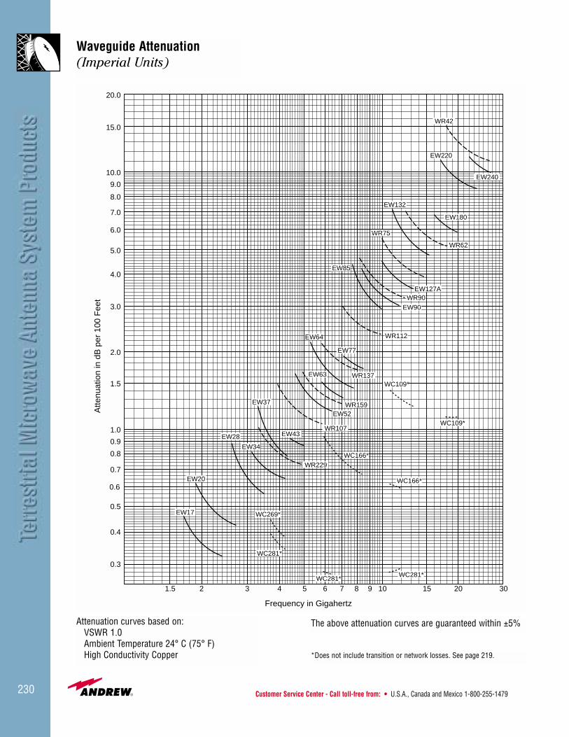
Customer Service Center - Call toll-free from: • U.S.A., Canada and Mexico 1-800-255-1479230
Waveguide Attenuation (Imperial Units)
Frequency in Gigahertz
Atte
nuat
ion
in d
B p
er 1
00 F
eet
1.5 2 3 4 5 6 7 8 9 10 15 20 30
0.3
0.4
0.5
0.7
0.8
0.9
1.0
1.5
2.0
3.0
4.0
5.0
6.0
7.0
8.0
9.0
10.0
15.0
20.0
WC281*WC281*
WC166*
WC281*
WC269*EW17
EW20
EW28
EW34
EW37
EW52WR159
EW63
EW64
WR137
EW77
WC109*
WC109*
WR112
EW85
EW90
WR90EW127A
WR75
EW132
WR62
EW180
EW220
WR42
WR229WC166*
WR107EW43
0.6
EW240
Attenuation curves based on:VSWR 1.0Ambient Temperature 24° C (75° F)High Conductivity Copper
The above attenuation curves are guaranteed within ±5%
*Does not include transition or network losses. See page 219.
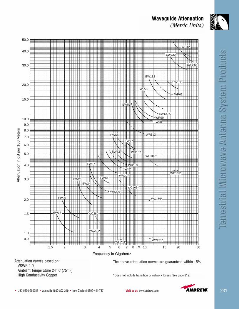
• U.K. 0800-250055 • Australia 1800-803 219 • New Zealand 0800-441-747 Visit us at: www.andrew.com 231
Frequency in Gigahertz
Atte
nuat
ion
in d
B p
er 1
00 M
eter
s
1.5 2 3 4 5 6 7 8 9 10 15 20 30
0.9
1.0
3.0
1.5
2.0
4.0
5.0
6.0
7.0
8.0
9.0
10.0
15.0
20.0
30.0
40.0
50.0
WC281*WC281*
WC166*
WC281*
WC269*EW17
EW20
EW28
EW34
EW37
EW52WR159
EW63
EW64
WR137
EW77
WC109*
WC109*
WR112
EW85
EW90
WR90EW127A
WR75
EW132
WR62
EW180
EW220
WR42
WR229WC166*
WR107EW43
EW240
Attenuation curves based on:VSWR 1.0Ambient Temperature 24° C (75° F)High Conductivity Copper
The above attenuation curves are guaranteed within ±5%
*Does not include transition or network losses. See page 219.
Waveguide Attenuation (Metric Units)


