185
Busduct System E-series, Mini-way, LT-way, MS/Wind-way, NSPB-LV/MV, CR-LV/MV, SIB, BTMS L S C & S B u s d u c t S y s t e m
| Date post: | 01-Jun-2018 |
| Category: |
Documents |
| Upload: | diego-santos |
| View: | 213 times |
| Download: | 0 times |

8/9/2019 Catalogo LSC_BUS_en_ÅëÇÕ
http://slidepdf.com/reader/full/catalogo-lscbusenaeco 1/184
Busduct SystemE-series, Mini-way, LT-way, MS/Wind-way,
NSPB-LV/MV, CR-LV/MV, SIB, BTMS

8/9/2019 Catalogo LSC_BUS_en_ÅëÇÕ
http://slidepdf.com/reader/full/catalogo-lscbusenaeco 2/184
About LS Cable & System
A New Beginning as a Total Solution Provider for Electric Power and Telecommunications
History was made when LS Cable & System, the de facto holding company of LS Group, transformed into LS Holding Company in July 2008 and started as a new
total-solution provider specialized in electric power and telecommunications. It was the optimized business decision to increase management efficiency of the
constantly expending business segments and to strengthen the responsible management system to foster a new growth engine to drive our business.
By separating investment and business segments, LS Holdings was able to discover a new growth engine to propel the group into a new phase of growth. The new
change of business provided an opportunity to the subsidiary companies to focus on their own operations and to strengthen their respective business expertise,
as well as successfully enhancing the competitiveness in the industry. LS Cable & System, as the holding company, is committed to providing continued support to
the subsidiary companies, while practicing responsible management.LS Cable & System endeavor to focus on our core business while strengthening its business
expertise and competitiveness as a global company.
Since the separation from LG Electronics in 2003, LS Group has specialized in industrial energy, electronic energy, and industrial materials.
Thus, LS Group has achieved specialized global competitiveness in these fields. LS Group is a parent company of 40 subsidiary companies,
including LS Cable & System, LSIS, LS Nikko Copper, LS Mtron, Gaon Cable, E1 and Yesco. LS Cable & System holds the unrivaled position of thetop cable maker in Korea, and it provides total solutions for electronic power and telecommunication industries.
LS Cable & System has strived to become a global leader in the industry by implementing constant innovation since the establishment of the company.
While providing high-quality solutions to help our clients, LS Cable & System is accelerating efforts to be the top player of the global cable industry by securing
the top technologies in submarine cables and superconducting cables, as well as focusing on green business. Under the company vision
’Your No.1 Creative Partner,’ LS Cable & System dedicates its best effort to deliver only the top technology and service to its clients.
Superior Essex
JS Cable
Global CableIncorporated
Pountek
LS Global
Power equipment, Power supply & transmission, Industrial IT,Automation equipment, Electric Power Tools, RFID etc.
• LS Cable & System
• LSIS
• LS Nikko Copper
• Gaon Cable
• E1
• Yesco
• Superior Essex
• LG Electronics
• LG Chemical
• LG Display
• LG Telecom
• GS Caltex
• GS Engineering & Construction
• GS Retail
• GS Homeshopping

8/9/2019 Catalogo LSC_BUS_en_ÅëÇÕ
http://slidepdf.com/reader/full/catalogo-lscbusenaeco 3/184
Standing Tall as the Third Largest Cable Maker in the Global Cable Industry
In August 2008, LS Cable & System acquired Super Essex, the largest cable maker in North America, making LS Cable & System the third largest cable maker
in the global cable industry. By incorporating the staple product line of coils and communication wires of Superior Essex to the existing business structure
of power cables, optical fiber cables, and wires of the company, LS Cable & System has built an ideal cable product line. Securing the extensive experience
of production and distribution network of Superior Essex in the markets of North America and Europe has led to LS Cable & System’s emergence as a true
global enterprise.
Superior Essex In 1999, Superior Cable, which back then was a communication cable producer, made an acquisition of Essex Wire, a magnet wire producer,
and the combination formed Superior Essex. The company is the world’s largest maker of magnet wires and the largest maker of communication cables in
North America. The company is headquartered in Atlanta, Georgia, USA, where they manage 24 factories in a total of 9 countries, including the United States,
Canada, Mexico, Germany, the UK, Italy, and China.
Components, Machinery
Supply of LPG for residential&commercial,transportation,industrial and petrochemical uses in domestic market.Import & Export of LPG etc.
LNG, CNG
Electrolytic Copper Cathode, Gold, Silver, Chemicals Product etc.

8/9/2019 Catalogo LSC_BUS_en_ÅëÇÕ
http://slidepdf.com/reader/full/catalogo-lscbusenaeco 4/184

8/9/2019 Catalogo LSC_BUS_en_ÅëÇÕ
http://slidepdf.com/reader/full/catalogo-lscbusenaeco 5/184
LS Cable & SystemBusduct System Solution
Apartment BuildingsAlthough the demands for more electricity for families are growing,
the space for EPS area has reduced. Due to the change,
the need for bus ducts and multi boxes have increased.
HospitalsThe stability of the power supply in the hospitals is perhaps the most vital element,
because its failure could threaten the safety of patients.
The Bus Duct system distributes larger capacity of electric power, and provides
stability of the loads which make it an ideal choice to satisfy the requirements of
systematization of hospital complexes and larger hospital equipments.
Marine & Wind The compact and light weight design of the bus duct satisfies the demands of the clients,
and comes with an outstanding quack resistance property. The bus duct provides stability
to the operation of the facilities through a real-time monitoring system using
a temperature and power monitoring system. As the needs for renewable energy grows,the demand for our bus duct has been increasing teadily.
AirportsIn order to secure the stable power supply of the airport, the bus duct system
provides the best customized solutions by installing high voltage bus ducts
at the transmission, transformation and power distribution lines, and by
installing low voltage bus ducts at the cargo, the control tower and general
commercial buildings.
StadiumsThe needs for a bus ducts system has been growing for its benefit such as
large capacity of power transmission, providing a stable power supply for
various loads and an eco friendly property as well as economical quality.
BuildingsThe LS C&S Bus Duct system is easy to install, and ensures large capacity of
energy transmission while providing space efficiency which makes the bus
duct system ideal for high-rise buildings, office buildings, data centers and
apartment complexes.
PlantsThe full lineup is consisting of NSPB that can cover up to 27kV as well as
CAST RESIN and SIB, and the lineup thus enables us to provide our clients
customized designs. The system is suitable for electrical rooms and power
lines, and it features a real time monitoring system using the temperature
and power monitoring system.
Data Center The flexibility and expandability as well as easy maintenance property
of the bus duct system provides the best alternative to improve the existing
problems of the conventional power cable system of data centers,
which requires constant extension, reinstallation and capacity
modification of loads.

8/9/2019 Catalogo LSC_BUS_en_ÅëÇÕ
http://slidepdf.com/reader/full/catalogo-lscbusenaeco 6/184
LS Cable & System Bus Duct ProductLine-up
Plug in Unit
Plug in Unit
Plug in Unit
Switchgear
Switchgear
Transformer
Transformer
Transformer
TR Flanged End Box
TR Flanged End Box
Rigid Hanger
Plug-in Box
Plug-in Box
Spring Hanger
Spring Hanger
Spring Hanger
Spring Hanger Plug-in Box
Plug-in Box
Rigid Hanger
End Closer
End Closer
Outdoor
Electrical Room
Vertical Ducts
Horizontal Ducts
2
1
2
1
3
7
6
5
4

8/9/2019 Catalogo LSC_BUS_en_ÅëÇÕ
http://slidepdf.com/reader/full/catalogo-lscbusenaeco 7/184
NSPB-LV/MV Air Insulated Type/Insulated conductors separated by phase/AL,
STS and Steel Housing/Indoor Type/Outdoor Type
- NSPB-LV : Designed for low voltage products below AC 1000V,and below 4000A
- NSPB-MV: Designed for high voltage products below AC 27kV, and below 4000A
- Suitable for plants where high stability is required.
5
Ez/Ex/EF-way Sandwich Type (PET Film, Epoxy Coating, MICA)/AL
Extrusion Housing/Standard IP54/Joint Kit
- Designed for low voltage products below AC 1000V, and between
630A to 7500A.
- The most widely used conventional model.
Mini-way Air Insulated Type/AL Extrusion Housing/Standard IP54/Joint Kit
- Designed for low voltage products below AC 1000V, and between
160A and 800A.
- Ideal for small distribution system with multi distribution loads
(Vertical areas of buildings, data centers, assemble factories)
The LS Cable & System Bus Ducts are available in a wide range of products from low voltage LT-Way (25A~63A) to high voltage E-Series(630A~7500A), and the products enable the supply of proper capacity of power for factories and the distribution system. Our products suchas the air insulated bus conducts with enhanced safety property and the cast resin bus ducts with resistance for high temperature, humidityand dusty environment will satisfy various application needs and provide a customized engineering service.
MS/Wind-way Air Insulated Type/ Compact NSPB Type / One-Bolting Type
Designed for low voltage products below AC 1000V, and between1000A and 5000A
- A Hybrid incorporating NSPB and sandwich type
- Ideal for ships, wind towers and chemical plants where stability is required.
LT-way Flat Wire Type/Copper Conductor with PVC Extruded Insulation/AL
Extrusion Housing/Various Plug Types/Joint Brush
(Can be installed with a live wire)
- Designed for low voltage products below AC 690V, and between 25A and 63A
- Suitable for Light bulbs, FFU and distribution for small equipments
SIBEpoxy Vacuum Impregnation Dielectric Products/Suitable for phase
separation system
- Designed for high voltage products below AC 27kV and below 7500A
- The benefit of bus ducts and cables are incorporated as SIB.
- Suitable for high voltage products.
1
2
3
4
CR-LV/MV - Cast Resin Type/IP 68/Dielectric Epoxy Molding between Conductors
- CR-LV: Designed for low voltage products below AC 1000V, and between
630A and7500A.
- CR-MV: Designed for high voltage products below AC 27KV,
and below 5000A.
- The most safe bus duct suitable for plants where high stability is required.
6
7

8/9/2019 Catalogo LSC_BUS_en_ÅëÇÕ
http://slidepdf.com/reader/full/catalogo-lscbusenaeco 8/184
Why Busduct?
The compact design of the bus duct system provides high space efficiency at up to 50% compared to the cables.While cables require larger space to install multi lines as well as additional space for coiling areas, the bus ducts use
proper fittings to maximize space efficiency.
Compact
BusductCable
Pulling and cable tray installation for cables can be difficult, and
requires a longer construction period, therefore increases the
cost. On the other hand, the bus ducts use a simple installationmethod to connect specific length of products, which requires a
shorter installation period, and is economically friendly.
Easy Initial Installation
When supplying power using cables, each load has to be connected individually to cables which waste space,
and an additional distribution panel is also required.
On the other hand, bus ducts are separated from a single line at a plug box which simplifies the electric power system.
A MCCB can be installed at the plug box to effectively shut off fault current.
• One –to-one correspondence of power
supply and loads
• Additional lines are needed in case of aload change
Cable Wiring System Bus Duct Wiring System
ACB : Air Circuit Breaker, MCCB : Molded Case Circuit Breaker
• One –to-many correspondence of power
supply for specific power supply
• Additional lines are not necessary in caseof a load change
Easy Distribution of Loads
P-1
MCCBACB ACB
P-2
P-3
P-...
P-x
L-1
L-2
L-3
L-...
L-x
... ...... ...
P-1
ACB ACB
P-2
P-3
P-...
P-x
L-1
L-2
L-3
L-...
L-x
Cable Tray
Cable
The space
required reduces
by 50%

8/9/2019 Catalogo LSC_BUS_en_ÅëÇÕ
http://slidepdf.com/reader/full/catalogo-lscbusenaeco 9/184
Cables require low short circuit capacity and additional rein-forcement facility. However, the bus duct system has a high
tolerance for short circuit. Its stability and reliability make it
perfect for a high capacity energy transmission system.
Excellent short circuit
Cables are connected directly to electric loads using racks.
The maximum allowable current ampacity limit is 1000A,and requires additional lines for a higher current. Each line
of the bus duct system can transmit up to 7500A, and pro-
vides high current density.
Unlike cables, the bus duct system does not require a shield,
instead the housing itself performs as a shield which en-
hances the features of EMC and EMI.
High current density
Outstanding features ofEMC andEMI
The design of the bus duct system makes it easy to detect
abnormalities during installations, and ensures easy main-tenance. When humidity or dust causes a malfunction on
the system, the easy-to -maintain design allows replacing
only the damaged part.
Easy maintenance
The bus duct system is a power distribution system and can
be applied to various complex routes. The bus duct system
comes with various fittings such as elbows, off-set and tee,
and can transmit high capacity currents without electrical
and mechanical loss.
Adaptability to various installationenvironment and convenience

8/9/2019 Catalogo LSC_BUS_en_ÅëÇÕ
http://slidepdf.com/reader/full/catalogo-lscbusenaeco 10/184
LS Cable & System has been a long-time leading cable maker of the bus duct market in Korea. With extensive experience and
product line competitiveness, the company provides total solutions for each application to satisfy the needs of its clients. Us-
ing its expertise in the electronic markets of large LCD monitors and semiconductors in Korea, the company has obtained PJT
sales records in 50 countries worldwide in Asia, the Middle East, CIS, and the US.
Why LS Cable &System Bus
LS Cable and System is the only global company that provides a full line-up of bus ducts, from low to high voltage and fromlow to high capacity, to satisfy every need of its clients and provide an optimized solution for each PJT.
Full Line – up
Global Top Tier
NSPB -LV/MV
SIB (MV)
Mini-way
CR-LV/MV
LT-way
Ez / Ex / Ef-way
MS/Wind-way

8/9/2019 Catalogo LSC_BUS_en_ÅëÇÕ
http://slidepdf.com/reader/full/catalogo-lscbusenaeco 11/184
Unparalleled Reliability
• Provides standardized design, and owns numerous certifications
such as UL Certification, Quack Proof Certification, and Impact
Resistance Certification
• The CS team, a task force for the bus duct system,
provides efficient after-sale service
• Safe use in hazardous zones• Manage the system using an independent temperature
monitor sensor
• Semi-permanent service life
• Used qualified insulation such as epoxy and PET film
for efficient insulation
Eco friendly
• Fully recyclable
• Halogen free
• Does not contain RoHS 6 hazardous substance
• No toxicity in fire & Fire-Retardant
• Non Explosive
Total Engineering Technology
• Provide the optimum design by experienced engineers
• Design following analysis and inspection of CAE
• Unique and exclusive design program for the bus duct system
• Design based on structure stability inspection
• The excellent heat –radiating property of the aluminum housing
ensures large capacity of power transmission
• Low Weight & Low cost
• Easy installation
• Deployable where access is difficult
• Automated epoxy insulation facility
• Unique joint kit connections
• Reduce electromagnetic
• BPMS Electric Power Monitoring System
• BTMS Temperature Monitoring System
Technical Excellence
Process
• Once PJT launches, our engineer will participate to guide the clients from the initial period in order to produce the best
system for our clients, and to respond quickly when the system is changed.• Our engineers from each department provide full support in design, production, installation and testing at in-bound to
satisfy our clients.
• We operate the CS Team, a task force for the bus duct system, to make sure efficient after-sale service and maintenance
service are provided.
Total Solution
• PJT Kick Off
• Production
• Customer Service
• Product test andinstallation support
• PJT management
• Provide technical supportfor the clients
• Product development
• System design
LS Cable & SystemBusduct
Total Solution
S a l e
s
D e s i g n a n d D e v e l o p
m e n t
I n s t a l l a
t i o n /
Q u a l i t y
/ C S
P r o d u
c t i o
n

8/9/2019 Catalogo LSC_BUS_en_ÅëÇÕ
http://slidepdf.com/reader/full/catalogo-lscbusenaeco 12/184
The Bus Duct Power Monitoring System
The Bus Duct Temperature Monitoring System
The ongoing trends of the bus duct system are more than a simple power supplying system. The growing trend is; 1) the stability ofthe power system, 2) unmanned system,3)cost cutting, and 4)green and smart grid. While the SCADA system monitors and controls
the power of the main system, the BMS monitors low loads of the sub system. The frequency of the resent electrical accidents is
higher at the sub system than at the main system. Therefore, the preference for the SCADA system has been increasing.
BPMS : Busduct Power Monitoring System
Ethernet
Smart box
Unit
485Ethernet
BTMS : Busduct Temperature Monitoring System
The bus duct is a large capacity power distribution system. The insulation of the duct has to stay stable when the Joule lines
occur during a power supply of the conductor. The rated current will be set by the insulation type, and the temperature rises.
These properties of the bus duct make it possible to monitor and manage abnormalities of the system by checking the
temperature of specific areas of the system.
The temperature monitoring system uses various temperature sensors such as optical fiber cable, IC electric chips and thermo-graphic cameras. Specific areas like the entire system line, joints, plug-in boxes and cable connection can be
monitored at the central monitor room using various methods on request.
Why LS C&S Bus Duct?

8/9/2019 Catalogo LSC_BUS_en_ÅëÇÕ
http://slidepdf.com/reader/full/catalogo-lscbusenaeco 13/184
Ez/Ex/Ef-way LS C&S Bus Duct System Catalogue
01 of 08
ContentsI. Introduction- Overview 14
- Application 15
II. General Data 16
III. Component
- Feeder 22
- Flanged End 23
- Fittings 26
- Hanger 29
- Plug-In Unit 31- Etc 33
IV. Technical Data
- Impedance 35
- Voltage Drop 36
- Temperature Rise 37
V. Install Information
- Joint Connection 38
VI. Certification & Specification 39

8/9/2019 Catalogo LSC_BUS_en_ÅëÇÕ
http://slidepdf.com/reader/full/catalogo-lscbusenaeco 14/184
I. Introduction
The LS C&S E-Series Bus Duct is designed to carry voltage range below AC 1000V, and to carry the current range of 633A to 7500A.Joint kit connections
provide more space to connect which reduce the contact resistance to its minimum while connecting products. LS C&S Bus Duct comes with a
standard IP54rating; however, it can be upgraded to an indoor or outdoor IP65 rating on request.
Depending on each insulation property the system comes in three types; Ez-way when polyester film is used, Ef-way when mica film is used and EX-way
is used when epoxy powder is used.
LS C&S E-Series Bus Duct uses an effective heat radiating housing profile which allows the size of the conductors to be smaller than the
existing Bus Duct models. The light weight of the Bus Duct also allows easier installation, and requires less space.
Compact Size
The E-Series
LS C&S E-Series Bus Duct uses aluminum housing and joint kit connections
which enable easy installation with less time and low cost.
Economical and Easy Installation
Easy Distribution of Loads
Overview
LSC&S E-Series Bus Duct can directly distribute the loads at the
plug-in box using a single line, and thus simplifies the power
supply system. The MCCB can be installed in the plug-in box
on request to effectively shut off the faulty current.
14 E-series LS C&S-Busway System

8/9/2019 Catalogo LSC_BUS_en_ÅëÇÕ
http://slidepdf.com/reader/full/catalogo-lscbusenaeco 15/184
06 / 07
Application
• The bus ducts can be applied to a vast range of industries such as
semiconductor, display and petrochemical plants.
• The temperature and the power supply monitoring system allows
easy maintenance.
• The bus ducts provides high space efficiency, and allowsa significantly reduced installation period.
Plants
• Provides excellent space efficiency.
• The bus ducts can be applied to high-rise buildings,
office buildings, and data centers.
• Multi-box can be applied on request.
Apartments and Large
• The bus duct can be installed both horizontally and vertically
at the electrical room.
• The maximized safety features are earthquake-proof and
explosion-proof.
• Provides excellent space efficiency and easy installation
compared to cables.
Electrical Rooms
I n t r o d u c t i on
E-series LS C&S-Busway System 15

8/9/2019 Catalogo LSC_BUS_en_ÅëÇÕ
http://slidepdf.com/reader/full/catalogo-lscbusenaeco 16/184
Ⅱ. General Data
Plug-in Box
Flanged End
Elbow
The cross sectional areas of the conductor and housing
profile are designed to meet the standard permissible
operating temperature of IEC 61439-2 and 6. Thereforethe temperature rise limit of the housing is within 55K
or less of the ambient temperature.
Permissible Operating Temperature
• Ambient Temperature : -15 Celsius to 55 Celsius
• Relative Humidity : 95% or below
(When the service condition of the environment doesmeet the requirements listed above, please contact our
design team.)
Service Condition
• IEC 61439-2 [(previous standard)IEC 60439-1] Power Switch gear and Control gear Assemblies
• IEC 61439-6 [(previous standard)IEC 60439-2]
Busbar Trunking Systems
• NSEN 60439 Busways
• NEMA BU 1.1 Busways
Standard Thanks to the optimum design, power can be transmittedwith the greatest possible efficiency, and the resultant
voltage drop is low due to extremely low impedance. In
addition, the LS C&S Bus Ducts is designed to have very
high short circuit strength.
Low Voltage Drop and High
The LS C&S Bus Ducts acquired RoHS certification, and
only uses components without hazardous substancessuch as lead, cadmium, mercury, chrome, PBBs and
PBDEs.
Environmentally
The bus duct has a compact design compared to the
existing models by using an effective heat-radiating
housing profile and can carry from 630Aup to 7500A
with reduced loss of electric power. It is an ideal powerdistribution system that provides high efficiency, stability,
economy-friendliness and convenience. The design of the
conductor allows flexibility to extend and relocatedepending on the environment.
High Current Density
16 E-series LS C&S-Busway System

8/9/2019 Catalogo LSC_BUS_en_ÅëÇÕ
http://slidepdf.com/reader/full/catalogo-lscbusenaeco 17/184
06 / 07
The E-Series uses either copper conductors with
conductivity over 99%, or aluminum conductorswith conductivity over 61%.
The connection of the conductors is tin-plated in
order to reduce contact resistance and to preventcorrosion of the connection. (A silver plated option
is available.)
Conductors
The E-Series uses an effective heat –radiating aluminum
housing profile which produces an excellent mechanicalstrength and heat radiation. The aluminum housing can
be used as a protective conductor due to its high level
conductivity and cross sectional areas. An optional optical
fiber temperature sensor can be installed at the housing.
Housing
An insulator of thermal class rating Class B (130 C)
or more is applied to the E-Series. Other insulation
options such as Epoxy, PET and MICA (Fire proof up
to 1200 C) are also available. FRP (Fiber ReinforcedPlastic) with high dielectric property is used as insulation
at the connection which performs as insulation between
phases and housing.
Insulation Properties Insulation Connections The E-Series uses a joint kit to connect the bus ducts. In
order to ensure easy maintenance and reliability, double
-headed bolts and visible labels (red tags) are used to
check the application, and a disc spring allows an evenconnection of the contact surface.(Connecting torque
800~1000kgf.cm)
The joint plate of the joint kit is tin plated in order to
prevent discoloration and corrosion.(A silver plated option
is available.)
G em er a l D a t a
Offset
Joint Kit
End Cap
E-series LS C&S-Busway System 17

8/9/2019 Catalogo LSC_BUS_en_ÅëÇÕ
http://slidepdf.com/reader/full/catalogo-lscbusenaeco 18/184
Ⅱ. General Data
General SpecificationsE-series bus duct uses insulation with a thermal class rating over130 C for each phase. A sandwich type design is applied to
the bus duct to protect the aluminum housing, and it can be used at the voltage range of AC 1000V or less, and the current
range between 630A to 7500A. It is designed to use a joint kit connection and general IP54 rating.
Aluminum housing coated with paint
Optical Fiber(Optional)
Optical Fiber Bracket(Optional)
Fastening Bolt & Washer
Conductor(Copper / Aluminum)
Insulation
- Ex-way by EPOXY
(Class B 130oC / Class F 155oC)
- Ez-way by PET
(Class B 130oC / Class F 155oC)
- Ef-way by MICA (1200oC)
18 E-series LS C&S-Busway System

8/9/2019 Catalogo LSC_BUS_en_ÅëÇÕ
http://slidepdf.com/reader/full/catalogo-lscbusenaeco 19/184
06 / 07
Precaution
Be sure to clean the interior of the connections prior to installation. Use caution not to twist the joint kit while inserting it, and after it is inserted.
An excessive pressure during installation may break the kit.
Make sure that the double-headed bolts and the red tags are intact.
If proper torqueses are not applied at the connection, it may cause heat during operation.
Double-headed bolts are used to ensure a proper torque level when installing
the joint kit. If a torque wrench applies a pressure of 800 to 1000kgf·cm to
the outer bolt head, the head of the outer bolt and the tag attached to it will be
sheared off automatically. Thus, it allows easy inspection for the proper applica-
tion of the bolts at the connection.
Specifics for the number of double-headed bolts required for each joint kit
Double Head Bolts
Both joint plates of the joint kit and the conductors are tin plated. (A silver
plated option is available.) It prevents the joint plate from discoloration and
corrosion. In order to ensure easy maintenance and reliability,
double-headed bolts and visible labels are used to check the application, and
a disc spring allows even connection of the contact surface.
Feature
Joint Kit Connection
!
G em er a l D a t a
Number of DH boltsNumber ofD.H bolts
CUAmpere
(A)AL
1
630, 800, 1000,1250, 1600, 2000
630, 800,
1000, 1250
2
2500, 3200,3600, 4000
1600,
2000, 2500
4
5000
3200,
3600, 4000
6
6300, 7500
5000, 6300
E-series LS C&S-Busway System 19

8/9/2019 Catalogo LSC_BUS_en_ÅëÇÕ
http://slidepdf.com/reader/full/catalogo-lscbusenaeco 20/184
Grounding and HarmonicsE-Series Bus Duct comes with aluminum housing, and the cross-section area of the housing is over 100% of each
phase conductor. Therefore, the aluminum housing alone works as 100% or more of ground bars, and the housing
also improves the heat radiation of the conductors.
The 200%N type Bus Duct is a nonlinear load bus duct that generates harmonic current. Lately, the needs for non-linear loads at the power distribution
system of buildings are increasing due to the increase of office automation and computer facilities. The harmonic current produced by the system can
flow up to 200% of over current at phase N. The LS C&S 200% N type bus duct is safe to be used at the distribution system where the harmonic current
can be generated.
[3W+GE]
[3W+50%E, 100%E]
[4W+GE]
[4W+50%E, 100%E]
[4W(200%N)+GE]
[4W(200%N) + 50%E]
Ⅱ. General Data
Plating/CoatingPlating
Standard tin plating is applied at taps, plugs and connectionsof conductors using an electroplating method to maintain theelectrical characteristics and to prevent corrosion. Silver plating isavailable on request.
Coating
In order to improve heat radiation and to prevent corrosion, aswell as to fit in with the surroundings, we treat the surface beforeapplying polyester-epoxy (hybrid) power coating. A wide range ofcolor is available to meet the needs of our clients.
20 E-series LS C&S-Busway System

8/9/2019 Catalogo LSC_BUS_en_ÅëÇÕ
http://slidepdf.com/reader/full/catalogo-lscbusenaeco 21/184
06 / 07
IP Code
*Outdoor applications require advanced discussion with the design team.
Degree of Protection
(IP)Bus Ducts Construction Type
IP54 Feeder, Plug-in, Riser Drip-proof / Splash-proof
IP54 is applied to the feeder, plug-in and tap-off, and can be
used during water leakages and near sprinklers.
With the IP65 rating, the bus duct is ideal for corrosive environments.
The special sealing between the housing sections seals off water,
dust and gasses.
Degree of Protection IP54 Degree of Protection IP65
Indoor and Outdoor Type Indoor Type Outdoor Type
Solid Particle Protection Liquid Ingress Protection
1m
15cmmin.
1m
No Protection
1
2
3
4
5
6
5
6
7
8
0
1
2
3
4
0
No Protection
IP
IP Code (Degree of Protection)International protection degree codes provided by IEC 60529(Degree of Protection Provided by Enclosure-IP Code)
The degree of protection against water of the LS C&S E-Series is a standard IP54; however, it can be adjusted from IP42
to IP65 depending on the environment and on request.
NEMA STANDARD : • IP54=NEMA 12, 12K, 13 • IP55=NEMA 3, 3X, 3S, 3SX • IP66=NEMA 4.4X • IP67=NEMA 6
* As the standard differs, it is a similar substitution, not 1:1 substitution.
G em er a l D a t a
E-series LS C&S-Busway System 21

8/9/2019 Catalogo LSC_BUS_en_ÅëÇÕ
http://slidepdf.com/reader/full/catalogo-lscbusenaeco 22/184
06 / 07
Flange(AL 4t) Flange(AL 4t) Flange(AL 4t) Flange(AL 4t)
Flanged End(GE)
*T: Conductor thickness
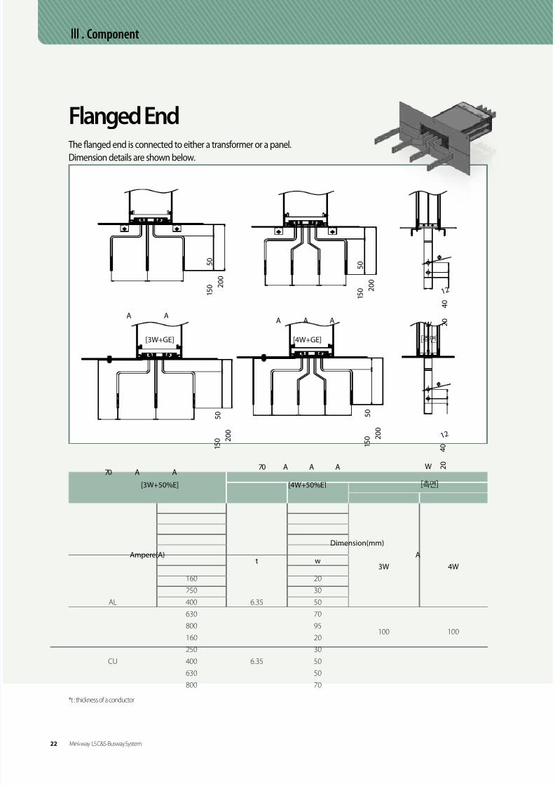
Flanged EndFlanged end is connected to either a transformer or a low-tension panel. Dimension details are listed below.
Ampere(A)Dimension(mm)
Fig.t W A B
AL
630
6.35
41 ~
100
E2-2800 62 ~
1,000 86 40E2-3
1,250 108 50
1,600 164 60E2-5
2,000 210 70
2,500 (2)126 40
130
E2-4
3,200 (2)164 60
E2-5
3,600 (2)184 60
4,000 (2)210 70
5,000 (3)184 60
6,300 (3)210 70
CU
630
6.35
41 ~
100
E2-2800 41 ~
1,000 57 ~
1,250 73 40E2-3
1,600 108 50
2,000 145 50 E2-4
2,500 195 70 E2-5
3,200 (2)108 50
130
E2-3
3,600 (2)126 40E2-4
4,000 (2)145 50
5,000 (2)195 706,300 (3)164 60 E2-5
7,500 (3)195 70
[Fig. E2-1]
[Fig. E2-2] [Fig. E2-3] [Fig. E2-4] [Fig. E2-5]
Flanged End(50%, 100%E)
C om p on en t
E-series LS C&S-Busway System 23

8/9/2019 Catalogo LSC_BUS_en_ÅëÇÕ
http://slidepdf.com/reader/full/catalogo-lscbusenaeco 23/184
Ⅲ. Component
Feeder
[Fig. E1-1] [Fig. E1-2]
[Fig. E1-3]
* H : 107.5(3W+GE, 3W+50%E) / 115(4W+GE, 4W+50%E) / 125(4W+100%E)
Ampere(A)Dimension(mm) Weight(kg/m)
Fig.t W A 3W 4W 4W+50%E 4W+100%E
AL
630
6.35
41 107 7.58 8.43 8.79 9.15
E1-1
800 62 128 8.83 10.09 10.63 11.17
1,000 86 152 10.92 12.14 12.89 13.64
1,250 108 174 13.40 15.42 16.36 17.30
1,600 164 230 19.57 20.61 22.08 23.55
2,000 210 276 23.08 26.23 28.14 30.09
2,500 (2)126 352 28.94 33.18 35.38 37.58
E1-23,200 (2)164 428 34.86 42.44 45.29 48.14
3,600 (2)184 468 38.31 45.40 48.59 51.78
4,000 (2)210 520 41.81 50.10 53.75 57.40
5,000 (3)184 686 57.74 68.43 73.22 78.01
E1-36,300 (3)210 764 64.03 73.61 81.51 89.41
CU
630
6.35
41 107 11.91 14.44 15.65 16.86
E1-1
800 41 107 11.91 14.44 15.65 16.86
1,000 57 123 14.65 18.25 20.58 22.91
1,250 73 139 17.65 22.04 24.60 27.16
1,600 108 174 26.74 31.00 36.47 41.94
2,000 145 211 31.69 37.39 44.76 52.13
2,500 195 261 42.69 54.59 60.25 65.91
3,200 (2)108 316 50.16 63.60 69.87 76.14
E1-23,600 (2)126 352 57.55 73.16 80.41 87.66
4,000 (2)145 390 64.82 82.72 91.17 99.62
5,000 (2)195 490 85.26 109.14 121.08 133.026,300 (3)164 626 108.91 139.27 154.65 168.02
E1-37,500 (3)195 719 126.89 162.81 179.83 196.85
AA
34 H H
t t
WW
Construction Options
A
34 34 H
t
W
22 E-series LS C&S-Busway System

8/9/2019 Catalogo LSC_BUS_en_ÅëÇÕ
http://slidepdf.com/reader/full/catalogo-lscbusenaeco 24/184
Ⅲ. Component
Flanged EndDrilling Pattern for Flanged End
A
A
A
B
B
B
D
D D
D
D
D
C1C1 C22525 25252525C1 C2C2
[Fig. E3-1] [Fig. E3-2] [Fig. E3-3]
Ampere(A)3W Dimension(mm) 4W Dimension(mm) 4W+50%E, 100% E Dimension(mm)
Fig.A B C1, C2 D A B C1, C2 D A B C1 C2 D
AL
630 240 122 110 152 340 122 160 152 410 122 230 160 152
E3-1
800 240 143 110 173 340 143 160 173 410 143 230 160 173
1,000 240 167 110 197 340 167 160 197 410 167 230 160 197
1,250 240 189 110 219 340 189 160 219 410 189 230 160 219
1,600 240 245 110 275 340 245 160 275 410 245 230 160 275
2,000 240 291 110 321 340 291 160 321 410 291 230 160 321
2,500 300 367 140 199 430 367 205 199 500 367 275 205 199
E3-23,200 300 443 140 237 430 443 205 237 500 443 275 205 237
3,600 300 483 140 257 430 483 205 257 500 483 275 205 257
4,000 300 535 140 283 430 535 205 283 500 535 275 205 283
5,000 300 701 140 244 430 701 205 244 500 701 275 205 244 E3-36,300 300 779 140 270 430 779 205 270 500 779 275 205 270
CU
630 240 122 110 152 340 122 160 152 410 122 230 160 152
E3-1
800 240 122 110 152 340 122 160 152 410 122 230 160 152
1,000 240 138 110 168 340 138 160 168 410 138 230 160 168
1,250 240 154 110 184 340 154 160 184 410 154 230 160 184
1,600 240 189 110 219 340 189 160 219 410 189 230 160 219
2,000 240 226 110 256 340 226 160 256 410 226 230 160 256
2,500 240 276 110 306 340 276 160 306 410 276 230 160 306
3,200 300 331 140 181 430 331 205 181 500 331 275 205 181
E3-23,600 300 367 140 199 430 367 205 199 500 367 275 205 199
4,000 300 405 140 218 430 405 205 218 500 405 275 205 218
5,000 300 505 140 268 430 505 205 268 500 505 275 205 2686,300 300 641 140 224 430 641 205 224 500 641 275 205 224
E3-37,500 300 734 140 255 430 734 205 255 500 734 275 205 255
24 E-series LS C&S-Busway System

8/9/2019 Catalogo LSC_BUS_en_ÅëÇÕ
http://slidepdf.com/reader/full/catalogo-lscbusenaeco 25/184
06 / 07
Flanged End Box / Feed in Box
[Fig. E4-2]
[Fig. E4-1]
Ampere(A)3W Dimension(mm) 4W Dimension(mm) 4W+50%E, 100% E Dimension(mm)
A B C D L A B C D L A B C D1 D2 L
AL
630 347 297 410 180X2 270 347 297 510 230X2 270 347 297 580 300 230 270
800 368 318 410 180X2 270 368 318 510 230X2 270 368 318 580 300 230 270
1,000 392 342 410 180X2 270 392 342 510 230X2 270 392 342 580 300 230 270
1,250 414 364 410 180X2 270 414 364 510 230X2 270 414 364 580 300 230 270
1,600 470 420 410 180X2 270 470 420 510 230X2 270 470 420 580 300 230 270
2,000 516 466 410 180X2 270 516 466 510 230X2 270 516 466 580 300 230 270
2,500 592 542 470 210X2 270 592 542 600 275X2 270 592 542 670 345 275 270
3,200 668 618 470 210X2 270 668 618 600 275X2 270 668 618 670 345 275 270
3,600 708 658 470 210X2 270 708 658 600 275X2 270 708 658 670 345 275 270
4,000 760 710 470 210X2 270 760 710 600 275X2 270 760 710 670 345 275 270
5,000 926 876 470 210X2 270 926 876 600 275X2 270 926 876 670 345 275 2706,300 1004 954 470 210X2 270 1004 954 600 275X2 270 1004 954 670 345 275 270
CU
630 347 297 410 180X2 270 347 297 510 230X2 270 347 297 580 300 230 270
800 347 297 410 180X2 270 347 297 510 230X2 270 347 297 580 300 230 270
1,000 363 313 410 180X2 270 363 313 510 230X2 270 363 313 580 300 230 270
1,250 379 329 410 180X2 270 379 329 510 230X2 270 379 329 580 300 230 270
1,600 414 364 410 180X2 270 414 364 510 230X2 270 414 364 580 300 230 270
2,000 451 401 410 180X2 270 451 401 510 230X2 270 451 401 580 300 230 270
2,500 501 451 410 180X2 270 501 451 510 230X2 270 501 451 580 300 230 270
3,200 556 506 470 210X2 270 556 506 600 275X2 270 556 506 670 345 275 270
3,600 592 542 470 210X2 270 592 542 600 275X2 270 592 542 670 345 275 270
4,000 630 580 470 210X2 270 630 580 600 275X2 270 630 580 670 345 275 270
5,000 730 680 470 210X2 270 730 680 600 275X2 270 730 680 670 345 275 2706,300 866 816 470 210X2 270 866 816 600 275X2 270 866 816 670 345 275 270
7,500 959 909 470 210X2 270 959 909 600 275X2 270 959 909 670 345 275 270
C om p on en t
E-series LS C&S-Busway System 25

8/9/2019 Catalogo LSC_BUS_en_ÅëÇÕ
http://slidepdf.com/reader/full/catalogo-lscbusenaeco 26/184
Ⅲ. Component
FittingsE-Series Bus Duct has a wide range of fittings to satisfy any layout of buildings. Elbow angles other than a ninety degree
angles are also available. Fitting designs are shown in the following figures, and they consist of the source-side and the
load-side. Offset or combination elbows can be used where standard elbows are not feasible.
(Dimensions for each fitting are shown in the following figures. Contact our design team for a minimum dimension.)
Elbow
Vertical Elbow
Offset
Vertical Offset
Ampere(A)Dimension(mm)
X Y
AL
630~1,250 500 500
1,600~3,200 600 600
3,600~4,000 700 700
5,000~6,300 800 800
CU
630~2,000 500 500
2,500~4,000 600 600
5,000~6,300 700 700
7,500 800 800
Ampere(A)Dimension(mm)
X Y Z
AL
630~1,250 500 150 500
1,600~3,200 600 150 600
3,600~4,000 700 150 700
5,000~6,300 800 150 800
CU
630~2,000 500 150 500
3,000~4,000 600 150 600
5,000~6,300 700 150 700
7,500 800 150 800
[Horizontal]
[Vertical]
[Horizontal]
[Vertical]
26 E-series LS C&S-Busway System

8/9/2019 Catalogo LSC_BUS_en_ÅëÇÕ
http://slidepdf.com/reader/full/catalogo-lscbusenaeco 27/184
06 / 07
Ampere(A)Dimension(mm)
X Y Z
AL
630~1,250 500 500 500
1,600~3,200 600 600 600
3,600~4,000 700 700 700
5,000~6,300 800 800 800
CU
630~2,000 500 500 500
3,000~4,000 600 600 600
5,000~6,300 700 700 700
7,500 800 800 800
Combination
Tee
Vertical Tee
600
600 600
600
600
600
Ampere(A)Dimension(mm)
X Y Z
AL
630~1,250 500 500 500
1,600~3,200 600 600 600
3,600~4,000 700 700 700
5,000~6,300 800 800 800
CU
630~2,000 500 500 500
3,000~4,000 600 600 600
5,000~6,300 700 700 700
7,500 800 800 800
[Horizontal] [Vertical]
C om p on en t
E-series LS C&S-Busway System 27

8/9/2019 Catalogo LSC_BUS_en_ÅëÇÕ
http://slidepdf.com/reader/full/catalogo-lscbusenaeco 28/184
Ⅲ. Component
FittingsExpansion
The fitting is designed to allow a 60mmextension of a straight line.
Phase Transformation FeederA phase transformation feeder is used when the setup transforms
the phase.
Ampere(A)Dimension(mm)
X Y
630~7,500 1,500 360
ReducerA reducer is used to connect a large capacity bus duct and a small capacity bus duct.
It can be used for an economical setup to distribute loads.
Ampere(A) Dimension(mm)
Primary Secondary X
1,000 630~800
1,000
1,250 800~1,000
1,600 1,000~1,250
2,000 1,250~1,600
2,500 1,600~2,000
3,200 2,000~2,500
4,000 2,500~3,200
5,000 3,200~4,000
6,300 4,000~5,000
7,500 5,000~6,300
*Any change made to load distribution or to capacities follows inner line regulations. An overcurrent circuit
breaker can be installed on request.
28 E-series LS C&S-Busway System

8/9/2019 Catalogo LSC_BUS_en_ÅëÇÕ
http://slidepdf.com/reader/full/catalogo-lscbusenaeco 29/184
06 / 07
HangerVertical Mounting HangersSpring hangers are used to support the bus ducts between floors. The number of springs depends on the weight of the installed ducts and plug-in boxes.
A medium hanger should be installed if the height between the floors exceeds 4.5 meters, and the height of the installed spring hangers can be easily
adjusted. Rigid hangers (no spring type) are used on the lowest floor, and they can be used instead of spring hangers depending on the set up design.
[Spring Hanger][Rigid Hanger]
* Hangers with more than 2 rows depending on the installation environment are also available on request.
Please contact the design team for further information.
Rigid Hanger
[1 Row] [2 Row] [Side View]
Spring Hanger
[1 Row] [2 Row] [Side View]
C om p on en t
E-series LS C&S-Busway System 29
8/9/2019 Catalogo LSC_BUS_en_ÅëÇÕ
http://slidepdf.com/reader/full/catalogo-lscbusenaeco 30/184
Ⅲ. Component
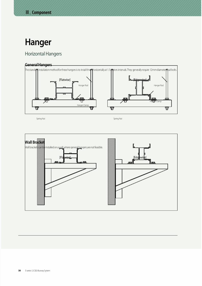
HangerHorizontal Hangers
[Flatwise] [Edgewise]
Wall BracketWall brackets can be installed on a wall where general hangers are not feasible.
General Hangers The standard installation method for these hangers is to install them horizontally at 1.5 meters intervals. They generally require 12mm diameter stud bolts.
[Flatwise] [Edgewise]
Spring Nut Spring Nut
Hanger Clamp
Hanger Clamp
Hanger Rod Hanger Rod
30 E-series LS C&S-Busway System

8/9/2019 Catalogo LSC_BUS_en_ÅëÇÕ
http://slidepdf.com/reader/full/catalogo-lscbusenaeco 31/184
06 / 07
This bus dust comes with an overcurrent blocking device (MCCB, fuse) in order to protect the wires while distributing loads.
The required minimum intervals of a plug-in(800A or less)and a tap-off(1000A, 1250A) are shown below. A length longer than
the required minimum intervals can be predestinated on request.
Straight Lengths: Plug-in/Tap-off Intervals
Plug-in Unit
Plug-in Feeder
Plug-in Box H ol eP i t c h ( P )
H
D
W
MCCB Frame
(AF)
Plug-in Hole Intervals(P)
(mm)
50, 65, 100 650
250 650
400 900
630, 800 1000
1000, 1250 1300
MCCB Frame
(AF)
Dimensions(mm)
Fig.WD H
3W 4W
50, 65, 100 200 250 220 450
E5-2250 200 250 220 450
400 250 300 220 750630, 800 350 400 220 800
1000, 1250 400 450 220 1200 E5-3
[Fig. E5-2] [Fig. E5-3]
[Fig. E5-1]
C om p on en t
E-series LS C&S-Busway System 31

8/9/2019 Catalogo LSC_BUS_en_ÅëÇÕ
http://slidepdf.com/reader/full/catalogo-lscbusenaeco 32/184
Attachments such as CT, TD and PT can be installed in a plug-in box to control and to supervise the current,
voltage and wattage remotely.
Plug-in Box Attachment Specifications
Various design of doors for the plug-in box is available to satisfy the demands of our clients.
The available types are shown below.
Production Specifications on the Doors
Ⅲ. Component
Plug-in Unit
External handle Push Button External lever interlock
Bolt Fastening Key Lock Outlet
32 E-series LS C&S-Busway System

8/9/2019 Catalogo LSC_BUS_en_ÅëÇÕ
http://slidepdf.com/reader/full/catalogo-lscbusenaeco 33/184
06 / 07
A wall flange is used to seal the gaps produced during installation of bus ducts at the walls, ceilings and floor. The standard
dimensions of a wall opening should be 30mm larger than the external dimensions of the E-Series Bus Duct.
Wall Flange
Etc.
Floor Openings The standard dimensions of a floor opening should be 30mm larger than the external dimensions of the E-Series Bus Duct.
Glass Wool(out of scope)
Fire Foam(out of scope)
Wall Flange
C om p on en t
E-series LS C&S-Busway System 33

8/9/2019 Catalogo LSC_BUS_en_ÅëÇÕ
http://slidepdf.com/reader/full/catalogo-lscbusenaeco 34/184
The required minimum distances between a bus duct and a wall, or a ceiling are shown below.
The required minimum distances between bus ducts are shown below.
The Required Minimum Distances from a Wall for Heat Dissipation
The required minimum distances between bus ducts
ⅢComponent
Etc.
250mm BEAM
100mm
100mm 100mm
100mm
200mm100mm
P2
200
200
100 100
P1 P3
200Standard Dimension (mm)
3W and 3W 3W and 4W 4W and 4W
P1 110 135 130
P2 150 175 180
P3 190 215 230
*Outdoor installation requires a further discussion with our design team about proper distance.
34 E-series LS C&S-Busway System

8/9/2019 Catalogo LSC_BUS_en_ÅëÇÕ
http://slidepdf.com/reader/full/catalogo-lscbusenaeco 35/184
06 / 07Ⅳ. Technical Data
Ampere(A)10-3Ω /100m, 60Hz Voltage Drop(V/100m)
R X Z 0.7 0.8 0.9 1
AL
630 13.98 4.07 14.56 13.85 14.87 15.66 15.25800 7.97 2.62 8.39 10.32 11.01 11.52 11.04
1,000 6.83 2.21 7.18 11.02 11.77 12.32 11.84
1,250 5.55 1.82 5.84 11.22 11.97 12.52 12.01
1,600 3.82 1.23 4.02 9.85 10.52 11.02 10.60
2,000 3.08 1.00 3.24 9.96 10.63 11.12 10.67
2,500 2.40 0.80 2.53 9.74 10.39 10.86 10.40
3,200 1.91 0.61 2.00 9.82 10.48 10.98 10.56
3,600 1.72 0.55 1.81 9.99 10.67 11.18 10.74
4,000 1.54 0.50 1.62 9.93 10.60 11.09 10.64
5,000 1.15 0.37 1.21 9.24 9.87 10.34 9.94
6,300 1.02 0.33 1.08 10.41 11.11 11.63 11.16
CU
630 7.49 4.07 8.53 8.90 9.21 9.30 8.18
800 7.49 3.84 8.42 11.07 11.50 11.67 10.38
1,000 5.49 2.99 6.25 10.35 10.72 10.82 9.52
1,250 4.39 2.45 5.03 10.44 10.78 10.86 9.50
1,600 3.10 1.71 3.54 9.40 9.72 9.80 8.60
2,000 2.40 1.35 2.76 9.17 9.46 9.53 8.32
2,500 1.86 1.05 2.13 8.87 9.16 9.22 8.06
3,200 1.54 0.85 1.76 9.34 9.66 9.75 8.55
3,600 1.35 0.74 1.54 9.20 9.51 9.60 8.42
4,000 1.20 0.67 1.37 9.13 9.42 9.49 8.29
5,000 0.93 0.52 1.06 8.84 9.13 9.19 8.03
6,300 0.73 0.39 0.83 8.62 8.93 9.02 7.97
7,500 0.62 0.35 0.71 8.83 9.12 9.18 8.02
Technical DataImpedance and Voltage Drop
The formula to measure the voltage drop of a bus duct is shown below. The impedance and voltage drop values for aluminum and copper
conductors are shown in the table below.
The values listed are measured between upper and middle lines at 60Hz. For a 50Hz installation, multiply the reactance (X) by 0.83.
T e c h ni c a l D a t a
C om p on en t
E-series LS C&S-Busway System 35

8/9/2019 Catalogo LSC_BUS_en_ÅëÇÕ
http://slidepdf.com/reader/full/catalogo-lscbusenaeco 36/184
Ampere(A)AL (kA) CU (kA)
1 sec 3 sec 1 sec 3 sec
630 24 14 36 21
800 42 24 36 21
1,000 50 29 51 29
1,250 62 36 65 371,600 95 55 95 55
2,000 121 70 129 75
2,500 132 76 150 107
3,200 169 97 191 110
4,000 200 140 200 149
5,000 200 150 200 200
6,300 200 150 200 200
7,500 - - 200 200
Phase to Phase Short Circuit Ratings
Ⅳ. Technical Data
Technical DataShort Circuit StrengthLS C&S Bus Duct has been tested under actual short circuit conditions according to IEC 61439-2 and 6 [(previous standard) IEC 60439-1 and 2]
at KEMA and ASTA. The result and the graph are shown below.
36 E-series LS C&S-Busway System

8/9/2019 Catalogo LSC_BUS_en_ÅëÇÕ
http://slidepdf.com/reader/full/catalogo-lscbusenaeco 37/184
06 / 07
The temperature rise limit is an important property which determines the performance of bus ducts. The temperature rise limit of the bus duct is
designed that when a bus duct is operated with a rated current , the temperature limit values of the housing are within 55K as specified in IEC61439-2
and 6 [(previous standard) IEC 60439-1 and 2].
Temperature Rise
Classification 1 2 3 4 5 6 7 8 9
Sensor Location Connection Conductor HousingAmbient
Temperature
Temperature Rise
Value58K 64K 60K 40K 32K 31K 31K 31K 24℃
80
70
60
50
40
30
20
10
0 1 2 3 4 5 6 7 8
T e m p
e r a t u r e ( )
Time(hr)
1
23
4
5 6
9
7 8
5
6
7 8
1 2 3 4
-Joint-
T e c h ni c a l D a t a
E-series LS C&S-Busway System 37

8/9/2019 Catalogo LSC_BUS_en_ÅëÇÕ
http://slidepdf.com/reader/full/catalogo-lscbusenaeco 38/184
Joint Connection
Once the exposed head and the red tag attached to it have been cut off, a red line should be visible, which means they are properly connected. Be sure
to check the distance from the housing, and the gaps between the conductors at the kit after the installation.
V. Install Information
Both parts should be aligned at the top and the bottom and the left and
the right as well as horizontally and vertically. (This also applies to the joint
connection of the horizontal and vertical ducts.) Make sure that the joint kit
is not tilted. (We recommend a jig tool for the installation.)
Using a torque wrench, slowly tighten the exposed bolt head of a double head
bolt. The double head bolt head is designed to break off at 800~1000Kgf • cm.
Continue tightening the exposed head until it breaks off.
Before applying the connection cover, check the space between the
end block and the holes of the connection cover. The red line should be
visible through the transparent cap.
투명 캡
Perform the last inspection of the connection.
38 E-series LS C&S-Busway System

8/9/2019 Catalogo LSC_BUS_en_ÅëÇÕ
http://slidepdf.com/reader/full/catalogo-lscbusenaeco 39/184
06 / 07
Certification & Specification
VI. Certification & Specification
UL Certification (Ex-way)
ASTA Certification (Ex-way)
CCC Certification(E-series)
KEMA Certification (Ex-way)
Dust and Water Proof Certification(E-series)
KS Certification(E-series)
ASTA Certification (Ez-way)
Fire Proof Certification (Ef-way) Fire Sprinkler Certification (Ef-way)
I n t a l l
I nf or m a t i on
C er t i fi c a t i on &
S p e c i fi c a t i on
E-series LS C&S-Busway System 39

8/9/2019 Catalogo LSC_BUS_en_ÅëÇÕ
http://slidepdf.com/reader/full/catalogo-lscbusenaeco 40/184
Certification & Specification
VI. Certification & Specification
OHSAS18001
TUV Eco Friendly Certification(Ef-way)
ISO9001
ISO14001
Quake Proof(E-series)
40 E-series LS C&S-Busway System

8/9/2019 Catalogo LSC_BUS_en_ÅëÇÕ
http://slidepdf.com/reader/full/catalogo-lscbusenaeco 41/184
Mini- way LS전선 Busduct System Catalogue
02 of 08
ContentsI. Introduction- Overview 14
- Application 15
II. General Data 16
III. Component
- Feeder 21
- Flanged End 22
- Fittings 24
- Hanger 26
- Plug-In Unit 27- Etc 28
IV. Technical Data
- Impedance 29
- Voltage Drop 29
- Temperature Rise 30
V. Install Information
- Joint Connection 31
VI. Certification & Specification 32

8/9/2019 Catalogo LSC_BUS_en_ÅëÇÕ
http://slidepdf.com/reader/full/catalogo-lscbusenaeco 42/184
I. Introduction
LSC&S Mini-way is an air insulation type bare conductor bus duct, and designed for low currents at AC 1000V or less or between 160A and 800A.
Each conductor is compounded with a class B rating insulating material (thermal class 130 C) and using a joint kit system
at the joint connections provides easy installation of feeders.
The mini-way comes with an IP54 rating and is water proof which reduces malfunction during operation caused by water leakage.
LS C&S Mini-Way is suitable for lager modern structures such as apartment complexes,
factories, shopping malls, and data center server rooms because of easy load distribution,
extension and installation. Our highly experienced and well-trained professionals can design
highly efficient products which will harmonize with surroundings and other equipments.
Safe and Efficient Distribution System
Mini-way
The light weight of LS C&S Mini-Way enables easy trans-
portation and installation, and employing the joint kit
system provides easy installation of the feeders.
Easy Installation
LS C&S Mini-Way follows the IEC standard, and has
designed the cross-section, conductor support and hous-
ing shape according to the regulations of temperature.
Therefore it has efficient voltage drop and high short
circuit strength.
Excellent Performance
Overview
14 Mini-way LS C&S-Busway System

8/9/2019 Catalogo LSC_BUS_en_ÅëÇÕ
http://slidepdf.com/reader/full/catalogo-lscbusenaeco 43/184

8/9/2019 Catalogo LSC_BUS_en_ÅëÇÕ
http://slidepdf.com/reader/full/catalogo-lscbusenaeco 44/184

8/9/2019 Catalogo LSC_BUS_en_ÅëÇÕ
http://slidepdf.com/reader/full/catalogo-lscbusenaeco 45/184
06 / 07
The Mini-Way uses either copper conductors with
conductivity over 99%, or aluminum conductors with
conductivity over 61%. The connection of the conductors is
tin-plated in order to reduce contact resistance and to
prevent to corrosion of the connection. (A silver plated
option is available.)
Conductors
The Mini-Way uses an effective heat –radiating aluminum
housing profile which produces an excellent mechanical
strength and heat radiation. The aluminum housing can
be used as a protective conductor (PE) thanks to its high
level conductivity and cross sectional areas.
Housing
The Mini-Way uses the air insulation system. The
insulation of thermal rating Class B (130 C) provides
high insulation performance between conductors
and between conductors and housing. In order to
secure the stability of conductor support and high
short circuit performance, the design is following
CAE (Computer Aided Engineering) instructions.
Insulation Properties Joint Kit
The Mini-Way uses joint kit to connect the bus ducts.
In order to ensure easy maintenance and reliability,
double-headed bolts and visible labels (red tags) are
used to check the application, and a disc spring allows
even connection of the contact surface.(Connecting
torque 800~1000kgf.cm)The joint plate of the joint kit is
tin plated in order to prevent discoloration and corrosion.
(A silver plated option is available.)
G em er a l D a t a
Feeder
Joint Kit
Elbow
Mini-way LS C&S-Busway System 17

8/9/2019 Catalogo LSC_BUS_en_ÅëÇÕ
http://slidepdf.com/reader/full/catalogo-lscbusenaeco 46/184
*Special capacity such as 4W(200%N)+100%E at [Cu 160~400A] can be produced on request.
Configration
[3W+GE] [4W+GE]
[3W+50%E] [4W+50%E]
[3W+100%E] [4W+100%E]
Ⅱ. General Data
General ConceptLSC&S Mini-Way is an air insulation type bare conductor bus duct, and it supports each phase with Class B rating insulating
material (thermal class 130 Celsius). It is designed for AC 1000V or less or between 160A and 800A. It also comes with a joint
kit system and standard IP54 rating.
18 Mini-way LS C&S-Busway System

8/9/2019 Catalogo LSC_BUS_en_ÅëÇÕ
http://slidepdf.com/reader/full/catalogo-lscbusenaeco 47/184
06 / 07
Grounding CapacityThe aluminum housing of the Mini-Way is designed to perform as a grounding conductor within the rated current. In
case 50~100% more grounding capacity is needed, an internal grounding conductor can be added without changing
the existing design.
Note
The aluminum housing itself acts as a grounding conductor and improves heat-radiation of conductors. The light weight of the mini-way was possible thanks
to the innovated design to reduce the weight.
[General Earth]
Housing
Housing
Housing
50% Earth
50% Earth
50% Earth
[50% Earth]
[100% Earth]
G em er a l D a t a
Mini-way LS C&S-Busway System 19

8/9/2019 Catalogo LSC_BUS_en_ÅëÇÕ
http://slidepdf.com/reader/full/catalogo-lscbusenaeco 48/184
Ⅱ. General Data
IPSolid Particle Protection Liquid Ingress Protection
1m
15cm min.
1m
No Protection
1
2
3
4
5
6
5
6
7
8
0
1
2
3
4
0
Protection against 50mmdiameter solid particles.(back of a hand)
Protection against dust.
Protected againstfalling drops of water.
Protected againstlow pressure jets of waterfrom all directions.
Protected against
strong jets of waterfrom all directions.
Protected against the effectsof immersion between15.0 centimeters and 1.0 meter.
Protected againstlonger periods of immersionunder pressure.
Protected against falling
drops of water with anenclosure tilted at a 15degreeangle from a vertical line
Protected againstspray sat a 60degreeangle from a vertical line
Protected againstwater splashed fromall directions.Complete protection
against dust.
Protection against 12mmsolid particles. (fingers)
Protection against 2.4mmsolid particles.(tools or thick wires)
Protection against 1mmsolid particles.(tools or most wires)
No Protection
IP Code (Degree of Protection)IP Code is an international protection degree code provided by IEC 60529(Degree of Protection Provided by Enclosure-IP Code)
NEMA STANDARD: • IP54=NEMA 12, 12K, 13 • IP55=NEMA 3, 3X, 3S, 3SX • IP66=NEMA 4.4X • IP67=NEMA 6
* As the standard differs, it is a similar substitution, nota 1:1 substitution.
The degree of protection against water of the Mini-Way is a standard IP54; however, it can be adjusted up to IP65.
An additional sealing using high strength silicon is also available at the joint connections between the housing and the
connection cover on request.
Plating and CoatingPlating
Standard tin plating is applied at taps, plugs and connections
of conductors using an electroplating method to maintain the
electrical characteristics and to prevent corrosion. Silver plating is
available on request.
Coating
In order to improve the heat radiation and to prevent corrosion, as
well as to fit in with the surroundings, we treat the surface before
applying polyester-epoxy (hybrid) power coating. A wide range of
color is available to meet the needs of our clients.
20 Mini-way LS C&S-Busway System

8/9/2019 Catalogo LSC_BUS_en_ÅëÇÕ
http://slidepdf.com/reader/full/catalogo-lscbusenaeco 49/184
8/9/2019 Catalogo LSC_BUS_en_ÅëÇÕ
http://slidepdf.com/reader/full/catalogo-lscbusenaeco 50/184
5 0
1 5 0 2
0 0
5 0
1 5 0 2
0 0
5 0
1 5 0 2
0 0
5 0
1 5 0 2
0 0
2 0
4 0
1 2
W
2 0
4 0
1 2
W
A
70 A A70 A A A
AA A A
Ⅲ. Component
Flanged EndThe flanged end is connected to either a transformer or a panel.
Dimension details are shown below.
[3W+GE] [4W+GE] [측면]
[3W+50%E] [4W+50%E] [측면]
*t : thickness of a conductor
Ampere(A)
Dimension(mm)
t wA
3W 4W
AL
160
6.35
20
100 100
250 30
400 50
630 70
800 95
CU
160
6.35
20
250 30
400 50
630 50
800 70
22 Mini-way LS C&S-Busway System

8/9/2019 Catalogo LSC_BUS_en_ÅëÇÕ
http://slidepdf.com/reader/full/catalogo-lscbusenaeco 51/184
06 / 07
D
B
A 5 0
C
C
Drilling Pattern for Flanged
Flanged End Box
500
L
B A
D
C
Ampere(A)Dimension(mm)
A B C D
AL
160 200
340
70
370
250 200 70
400 220 80
630 240 100
800 265 125
Ampere(A)Dimension(mm)
A B C D
CU
160 200
340
70
370
250 200 70
400 220 80
630 220 80
800 240 100
Ampere(A)Dimension(mm)
t W A B C D L
AL
160
6.35
20 190 130
510 450 270
250 30 200 140
400 50 220 160
630 70 240 180
800 95 265 205
CU
160
6.35
20 190 130
510 450 270
250 30 200 140
400 50 220 160
630 50 220 160
800 70 240 180
C om p on en t
Mini-way LS C&S-Busway System 23

8/9/2019 Catalogo LSC_BUS_en_ÅëÇÕ
http://slidepdf.com/reader/full/catalogo-lscbusenaeco 52/184
Ⅲ. Component
FittingsE-Series Bus Duct has a wide range of fittings to satisfy any layout of buildings. Elbow angles other than 90 degrees are also
available. Fitting designs are shown in the following figures, and they consist of the source-side and the load-side. Offset
or combination elbows can be used where standard elbows are not feasible.(Dimensions for each fitting are shown in the
following figures. Contact our design team for a minimum dimension.)
Elbow
[Vertical] [Horizontal]
Offset[Vertical] [Horizontal]
Y
X
Z
X
Y
YX
Y
X
Z
Ampere(A)Dimension(mm)
X Y
160 ~ 800 500 500
Ampere(A)Dimension(mm)
X Y Z
160 ~ 800 500 500 500
Ampere(A)Dimension(mm)
X Y Z
160 ~ 800 500 500 500
Ampere(A)Dimension(mm)
X Y
160 ~ 800 500 500
24 Mini-way LS C&S-Busway System

8/9/2019 Catalogo LSC_BUS_en_ÅëÇÕ
http://slidepdf.com/reader/full/catalogo-lscbusenaeco 53/184
06 / 07
Tee
Combination
[Vertical] [Horizontal]
Z
X
Y
X
Y
Z
X
Y
Z
H
Ampere(A)Dimension(mm)
X Y Z
160 ~ 800 500 500 500
Ampere(A)Dimension(mm)
X Y Z
160 ~ 800 500 500 500
Ampere(A)Dimension(mm)
X Y Z
160 ~ 800 500 500 500
Ampere(A)Dimension(mm)
X Y Z
160 ~ 800 500 500 500
Ampere(A)Dimension(mm)
H_AL H_CU
160 134 134
250 144 144
400 164 164
630 184 164
800 209 184
C om p on en t
Mini-way LS C&S-Busway System 25

8/9/2019 Catalogo LSC_BUS_en_ÅëÇÕ
http://slidepdf.com/reader/full/catalogo-lscbusenaeco 54/184
Hanger Clamp Hanger Clamp
Hanger Rod 12Ø Hanger Rod 12Ø
Ⅲ. Component
Horizontal Hangers
[Spring Hanger]
Vertical Hangers
[Rigid Hanger]
- Front Type -
- Front Type -
- Side Type -
- Side Type -
HangerBus ducts installed on the ceilings, floors, walls and beams are usually supported by stud bolts, system channels, angles
and channels. Various types of hangers are available depending on the installation condition or environment. (Please con-
tact our design team for further information about hanger types and installation.)
[Flatwise] [Edgewise]
Base Channel
Base Channel
26 Mini-way LS C&S-Busway System

8/9/2019 Catalogo LSC_BUS_en_ÅëÇÕ
http://slidepdf.com/reader/full/catalogo-lscbusenaeco 55/184
06 / 07
C om p on en t
Plug-in UnitThe position of the plug-in distribution location will be decided according to the installation environment and on
request. The standard length of the feeders is 3 meters, and a maximum of 8 plug-in holes can be made on a 3 meter
feeder. In order to secure the smooth access between the plug-in brushes and feeders, a guide pin has been attached
Attachments such as CT, TD and PT can be installed in a plug-in box to control and to supervise current, voltage and wattage remotely.
Plug-in Box
External handle
Bolt Fastening
Push Button External lever interlock
Outlet
Guide Pin Hole
Guide Pin
Various design of doors for the plug-in box is available to satisfy the demands of our clients.
The available types are shown below.
Production Specifications for the Doors
Key Lock
Mini-way LS C&S-Busway System 27

8/9/2019 Catalogo LSC_BUS_en_ÅëÇÕ
http://slidepdf.com/reader/full/catalogo-lscbusenaeco 56/184
Ⅲ. Component
The Required Minimum Distances from a Wall for Heat Dissipation
100
2 0 0
100
1 0 0
250mm Beam
Joint Point
100
1 0 0
A wall flange is used to seal the gaps produced during installation of bus ducts at the walls,
ceilings and floors.
Etc.Wall Flange Floor Opening
W+160
Wall Open SizeCut Out
W+60
W+10
H + 1 6 0
H + 6 0
H + 1 0
• W : The width of the product (165mm)
• H : The height of the product (It is decided by a rated current.)
• W : The width of the product (165mm)
• H : The height of the product
(It is decided by a rated current.)
Glass Wool(out of scope)
Wall Flange Fire Foam(out of scope)
Wall, ceiling
28 Mini-way LS C&S-Busway System

8/9/2019 Catalogo LSC_BUS_en_ÅëÇÕ
http://slidepdf.com/reader/full/catalogo-lscbusenaeco 57/184

8/9/2019 Catalogo LSC_BUS_en_ÅëÇÕ
http://slidepdf.com/reader/full/catalogo-lscbusenaeco 58/184
The temperature rise limit is an important property which determines the performance of bus ducts. The temperature rise
limit of the bus duct is designed so that when a bus duct is operated with a rated current, the temperature limit values of the
housing are within 55K as specified in IEC61439-2 and 6 [(previous standard) IEC 60439-1 and 2].
Temperature Rise
Classification 1 2 3 4 5 6 7 8 9
Censer Location Connection Conductor Housing Ambient
Temperature
Temperature Rise
Value75K 79K 80K 61K 39K 32K 52K 53K 23℃
Ⅳ. Technical Data
Technical Data
80
70
60
50
40
30
20
10
0 1 2 3 4 5 6 7 8
5
6
7 8
1 2 3 4
T e m p
e r a t u r e ( )
Time(hr)
-Joint-
1
2 3
4
5
6
9
7 8
30 Mini-way LS C&S-Busway System

8/9/2019 Catalogo LSC_BUS_en_ÅëÇÕ
http://slidepdf.com/reader/full/catalogo-lscbusenaeco 59/184
06 / 07Ⅴ. Install Information
Joint Connection
Both parts should be aligned at the top and the bottom and the left and
the right as well as horizontally and vertically. (This also applies to the joint
connection of the horizontal and vertical ducts.) Make sure that the joint
kit is not tilted. (We recommend a jig tool for the installation.)
Once the exposed head and the red tag attached to it have been cut off,
a red line should be visible, which means they are properly connected.
Before applying the connection cover, check the space between the endblock and the holes of the connection cover.
Using a torque wrench, slowly tighten the exposed bolt head of a
double head bolt. The double head bolt head is designed to break
off at 800~1000Kgf•cm. Continue tightening the exposed head until
it breaks off.
Be sure to check the distance from the housing, and the gaps between the
conductors at the kit after the installation.
Perform the last inspection of the connection. (Follow the instruction ofthe installation manual for additional sealing according to the IP Code)
1
3
5
2
4
6
T e c h ni c a l D a t a
I n t a l l
I nf or m a t i on
Mini-way LS C&S-Busway System 31

8/9/2019 Catalogo LSC_BUS_en_ÅëÇÕ
http://slidepdf.com/reader/full/catalogo-lscbusenaeco 60/184
Certification & Specification
VI. Certification & Specification
Refractoriness Certification Dust proof and Water proof Certification
ISO9001 ISO14001
KEMA Certification KEMA Certification KEMA Certification
OHSAS18001
TUV Eco Friendly Certification
32 Mini-way LS C&S-Busway System

8/9/2019 Catalogo LSC_BUS_en_ÅëÇÕ
http://slidepdf.com/reader/full/catalogo-lscbusenaeco 61/184
ContentsI. Introduction- Overview 14
- Application 15
II. General Data 16
III. Component
- Feeder 19
- Feed in Unit 22
- Flexible Fitting 23
- End Cover 24
- Hanger 24- Plug In Unit 25
IV. Technical Data
- Impedance 26
- Voltage Drop 26
- Temperature Rise 27
V. Install Information
- Joint Connection 28
- Plug-in Unit Installation 28
VI. Certification & Specification 29
LT- WAY LS전선 Busduct System Catalogue
03 of 08

8/9/2019 Catalogo LSC_BUS_en_ÅëÇÕ
http://slidepdf.com/reader/full/catalogo-lscbusenaeco 62/184

8/9/2019 Catalogo LSC_BUS_en_ÅëÇÕ
http://slidepdf.com/reader/full/catalogo-lscbusenaeco 63/184

8/9/2019 Catalogo LSC_BUS_en_ÅëÇÕ
http://slidepdf.com/reader/full/catalogo-lscbusenaeco 64/184
Ⅱ. General Data
The compact and light weight design of aluminum
pressing-out type housing is suitable for low capacity
power lines between 25 to 63A.
Weight
The cross sectional areas of the conductor and housing
profile are designed to meet the standard permissible
operating temperature of IEC 61439-2 and 6. Thereforethe temperature rise limit of the housing is within 55K
or less of the ambient temperature.
Permissible Operating Temperature
Each feeder (3 meters) can have a maximum 10 load
distributions installed, and provide them easily.
Easy Load Distribution
• Ambient Temperature : -15 Celsius to 55 Celsius
• Relative Humidity : 95% or below
(When the service condition of the environment doesmeet the requirements listed above, please contact our
design team.)
Service Condition
• IEC 61439-2 [(previous standard)IEC 60439-1]
Power Switchgear and Controlgear Assemblies
• IEC 61439-6 [(previous standard)IEC 60439-2]
Busbar Trunking Systems
Standard
The LS C&S Bus Ducts acquired RoHS certification, and
only uses components without hazardous substances
such as lead, cadmium, mercury, chrome, PBBs and
PBDEs.
Environmentally Friendly
Plug-in Unit
Plug-in Hole
Feed-in Unit
16 LT-way LS C&S-Busway System

8/9/2019 Catalogo LSC_BUS_en_ÅëÇÕ
http://slidepdf.com/reader/full/catalogo-lscbusenaeco 65/184
06 / 07
The conductor uses over 99 percent pure copper flat
wire consisting of 2 or 4 fibers. Elongated marks have
been etched in order to prevent slips when pressed.
The LT-Way comes with high molecule insulation
of a fire proof grade A rating. The intervals between
insulations have been designed for the optimum
functionality as specified in CAE (Computer Aided
Engineering).
Conductors
The high strength aluminum housing can be used
as a protective conductor (PE) due to its high level
conductivity and mechanical strength. Variety of
coating options for the housing is available on request.
Housing
Other than the connections and the PH, the conductor
has been insulated which prevent accidents caused by
impacts. The insulation uses PVC which has the fire proof
grade A rating (105℃) according to IEC regulations.
Insulation Joint Brush The Joint brush can be safely and easily connected
with a live wire. Optional double cover is available.
The double enhances the strength against impacts.
Plug-in Unit
Flexible Fitting
Feeder
LT-way LS C&S-Busway System 17
G em er a l D a t a

8/9/2019 Catalogo LSC_BUS_en_ÅëÇÕ
http://slidepdf.com/reader/full/catalogo-lscbusenaeco 66/184

8/9/2019 Catalogo LSC_BUS_en_ÅëÇÕ
http://slidepdf.com/reader/full/catalogo-lscbusenaeco 67/184
06 / 07
FeederThe standard length of feeders is either 3 meters or 1.5 meters,
and 5 plug-in holes can be applied on each side of a
3 meter feeder (maximum 10 holes).
For a 1.5 meter feeder, 3 plug-in holes can be applied
on each side (maximum 6 holes).
W
H Ø
Ampere(A)Dimension(mm)
H W 외경Φ
CU
25
30 50
1.8
40
2.863
Ⅲ. Component
LT-way LS C&S-Busway System 19
G em er a l D a t a
C om p on en t

8/9/2019 Catalogo LSC_BUS_en_ÅëÇÕ
http://slidepdf.com/reader/full/catalogo-lscbusenaeco 68/184
FeederA single housing can handle two lines (R, S, T, NX2), and the 3-phase 4-wire system supplies larger capacity than a single
phase which decrease the line imbalance.
Standard of ProductAmpere Wire Tier Length Plug-in hole Weight Cat No.
A W Tier mm EA g/m No.
STD. Feeder
(Ph + N + PE)
25 2 1 3000 0
2355
LSLT F252130
25 2 1 3000 2 LSLT F252132
25 2 1 3000 3 LSLT F252133
25 2 1 3000 5 LSLT F252135
25 2 1 1500 21260
LSLT F252112
2 2 1 1500 3 LSLT F252113
40 2 1 3000 0
2520
LSLT F402130
40 2 1 3000 2 LSLT F402132
40 2 1 3000 3 LSLT F402133
40 2 1 3000 5 LSLT F402135
40 2 1 1500 21340
LSLT F402112
40 2 1 1500 3 LSLT F402113
STD. Feeder
(3Ph + N + PE)
25 4 1 3000 0
2615
LSLT F254130
25 4 1 3000 2 LSLT F254132
25 4 1 3000 3 LSLT F254133
25 4 1 3000 5 LSLT F254135
25 4 1 1500 21390
LSLT F254112
25 4 1 1500 3 LSLT F254113
40 4 1 3000 0
2970
LSLT F404130
40 4 1 3000 2 LSLT F404132
40 4 1 3000 3 LSLT F404133
40 4 1 3000 4 LSLT F404134
40 4 1 3000 5 LSLT F404135
40 4 1 1500 21565
LSLT F404112
40 4 1 1500 3 LSLT F404113
STD.Feeder
(3Ph+N+PE)
63 4 1 3000 0
3860
LSLTF634130
63 4 1 3000 2 LSLTF634132
63 4 1 3000 3 LSLTF634133
63 4 1 1500 5 LSLTF634135
63 4 1 1500 22010
LSLTF634112
63 4 1 3000 3 LSLTF634113
Ⅲ. Component
20 LT-way LS C&S-Busway System

8/9/2019 Catalogo LSC_BUS_en_ÅëÇÕ
http://slidepdf.com/reader/full/catalogo-lscbusenaeco 69/184
06 / 07
Standard of ProductAmpere Wire Tier Length Plug-in hole Weight Cat No.
A W Tier mm EA g/m No.
STD. Feeder
(Ph + N + PE) x 2
25 6 2 3000 0
2615
LSLT F256230
25 6 2 3000 2 LSLT F256232
25 6 2 3000 3 LSLT F256233
25 6 2 3000 5 LSLT F256235
25 6 2 1500 21390
LSLT F256212
25 6 2 1500 3 LSLT F256213
40 6 2 3000 0
2970
LSLT F406230
40 6 2 3000 2 LSLT F406232
40 6 2 3000 3 LSLT F406233
40 6 2 3000 5 LSLT F406235
40 6 2 1500 21565
LSLT F406212
40 6 2 1500 3 LSLT F406213
STD. Feeder
(3Ph + N + PE)(Ph + N + PE)
25 6 2 3000 0
2890
LSLT F256230
25 6 2 3000 2 LSLT F256232
25 6 2 3000 3 LSLT F256233
25 6 2 3000 5 LSLT F256235
25 6 2 1500 21525
LSLT F256212
25 6 2 1500 3 LSLT F256213
40 6 2 3000 0
3415
LSLT F406230
40 6 2 3000 2 LSLT F406232
40 6 2 3000 3 LSLT F406233
40 6 2 3000 5 LSLT F406235
40 6 2 1500 21790
LSLT F406212
40 6 2 1500 3 LSLT F406213
STD. Feeder
(3Ph + N + PE) x 2
25 8 2 3000 0
3175
LSLT F258230
25 8 2 3000 2 LSLT F25823225 8 2 3000 3 LSLT F258233
25 8 2 3000 5 LSLT F258235
25 8 2 1500 21670
LSLT F258212
25 8 2 1500 3 LSLT F258213
40 8 2 3000 0
3860
LSLT F408230
40 8 2 3000 2 LSLT F408232
40 8 2 3000 3 LSLT F408233
40 8 2 3000 5 LSLT F408235
40 8 2 1500 22010
LSLT F408212
40 8 2 1500 3 LSLT F408213
LT-way LS C&S-Busway System 21
C om p on en t

8/9/2019 Catalogo LSC_BUS_en_ÅëÇÕ
http://slidepdf.com/reader/full/catalogo-lscbusenaeco 70/184

8/9/2019 Catalogo LSC_BUS_en_ÅëÇÕ
http://slidepdf.com/reader/full/catalogo-lscbusenaeco 71/184

8/9/2019 Catalogo LSC_BUS_en_ÅëÇÕ
http://slidepdf.com/reader/full/catalogo-lscbusenaeco 72/184
The end cover is applied at the end of a rail,
and the capacity for the covers is the same.
End Cover
33 24
5 3
9333
5 3
General Type
HangerDirect Type
• The hangers are designed to install the bus ducts at buildings.
• They can be either installed directly to the ceiling, or at the hanger rods.
• The standard installation interval between hangers is 1.5 meters. Caution) When the hangers are used to fix lamps, avoid the joint connections.
Product Install Method
Maximum
Load
kg
General TypeIt is installed at the
hanging bolt.60
Direct TypeIt is installed at the
fixing band.60
Ⅲ. Component
NotePlease contact out design team if a special type of hangers (Tee or Reducer) are required due to the installation environment.
Capacity Source/Load Cat No.
A Source / Load No.
25 Source LSLT ES
25 Load LSLT EL
40 Source LSLT ES
40 Load LSLT EL
63 Source LSLT ES
63 Load LSLT EL
24 LT-way LS C&S-Busway System

8/9/2019 Catalogo LSC_BUS_en_ÅëÇÕ
http://slidepdf.com/reader/full/catalogo-lscbusenaeco 73/184
06 / 07
The load distribution system can be either installed or removed with a live line. The unit is a double-sided
clamp to connect a conductor, and incombustible materials have been used for the insulation and plastic
Plug-in Unit
Fuse TypeIt is the same type as the phase selection type; however, the fuse type
comes with a fuse for each phase to protect faulty current and overcur-
rent caused by load distribution.
Product Capacity(A) Phase Cat No. (No)
고정형 10/16A
L1+N LSLT P10F1
L2+N LSLT P10F2
L3+N LSLT P10F3
이동형 10/16A
L1+N LSLT P10S1
L2+N LSLT P10S2
L3+N LSLT P10S3
L1+L2 LSLT P10S12L1+L3 LSLT P10S13
L2+L3 LSLT P10S23
L1+L2+L3+N LSLT P10S4
Fuse형 10/16A
L1+N LSLT P10FU1
L2+N LSLT P10FU2
L3+N LSLT P10FU3
L1+L2 LSLT P10FU12
L1+L3 LSLT P10FU13
L2+L3 LSLT P10FU23
L1+L2+L3+N LSLT P10FU4
Phase Selection Type The adaptability of this type provides options to select a suitable phase
depending on the situation of the installation environment. The internal
process of the type can be checked through the transparent cover.
Plug-in TypeIt is designed for low capacity products (63A or less). Easy to use and a
1-outlet or 3-outlet plug-in is available.
Phase Joint Type
It is usually used for single phase products,
and the design maximizes the convenience.
1 outlet 3 outlet
Product Capacity(A) Phase Cat No.(No)
1 outlet 10/16
L1+N LSLT P10S1
L2+N LSLT P10S2
L3+N LSLT P10S3
L1+L2 LSLT P10S12
L1+L3 LSLT P10S13
L2+L3 LSLT P10S23
L1+L2+L3+N LSLT P10S4
3 outlet 10/16
L1+N LSLT P10FU1
L2+N LSLT P10FU2
L3+N LSLT P10FU3
L1+L2 LSLT P10FU12
L1+L3 LSLT P10FU13
L2+L3 LSLT P10FU23
L1+L2+L3+N LSLT P10FU4
LT-way LS C&S-Busway System 25
C om p on en t

8/9/2019 Catalogo LSC_BUS_en_ÅëÇÕ
http://slidepdf.com/reader/full/catalogo-lscbusenaeco 74/184
LT-Way has been tested under actual short circuit conditions according to IEC 61439-2 and 6 [(previous standard)
IEC 60439-1 and 2].
Technical Data
Impedance and Voltage Drop
Short Circuit Strength
Ⅳ. Technical Data
Ampere(A)
10-3Ω /100m, 60Hz Voltage Drop(V/100m)
R X Z 0.7 0.8 0.9 1
CU
25 8.1 0.2 8.1 0.25 0.29 0.32 0.35
40 3.35 0.167 3.4 0.17 0.19 0.21 0.23
63 1.67 0.141 1.7 0.14 0.16 0.17 0.18
The formula to measure the voltage drop of a bus duct is shown below. The impedance and voltage drop values for aluminum and
copper conductors are shown in the table below.
The values listed are measured between the upper and middle lines at 60Hz. For a 50Hz installation, multiply the reactance (X) by 0.83.
Ampere(A)Copper(kA)
1 sec. 3 sec.
25 0.6 0.34
40 1.4 0.8
63 1.4 0.8
26 LT-way LS C&S-Busway System

8/9/2019 Catalogo LSC_BUS_en_ÅëÇÕ
http://slidepdf.com/reader/full/catalogo-lscbusenaeco 75/184
06 / 07
The temperature rise limit is an important property which determines the performance of bus ducts. The temperature rise limit of the bus duct is
designed so that when a bus duct is operated with a rated current , the temperature limit values of the housing are within 55K as specified
in IEC61439-2 and 6 [(previous standard) IEC 60439-1 and 2].
Temperature rise
Classification 1 2 3 4 5 6 7 8 9
Censer Location Connection Conductor HousingAmbient
Temperature
Temperature Rise
Value46K 49K 46K 40K 15K 14K 15K 14K 12℃
80
70
60
50
40
30
20
10
0 1 2 3 4 5 6 7 8
T e m
p e r a t u r e ( )
Time(hr)
5
6
7 8
1 2 3 4
-Joint-
1
2
3
4
5
6
9
7
8
LT-way LS C&S-Busway System 27
T e c h ni c a l D a t a

8/9/2019 Catalogo LSC_BUS_en_ÅëÇÕ
http://slidepdf.com/reader/full/catalogo-lscbusenaeco 76/184
Joint Connection
Plug-in Unit Installation
1) Check the condition of the joint, and loosen the cross heads
of the protection cover.
Open the plug cover as shown below, and insert an appropriate plug-in unit or an outlet plug.
2) Insert the end into the other as shown in the image below,
and tighten the cross heads.
Caution
Caution
Make sure the plug-in holes are clean before inserting the plug-in unit. Be sure to check the phase of unit and the plug.
Make sure to clean the parts of the joint before installation. Proceed with caution since the joint can be damaged by impacts.Be sure to keep them straight and steady to connect.
Caution) Don’t loosen the hexagon bolts for they fix the
products in place.
(O) (X)
(O)
(X)
Ⅴ. Install Information
!
!
28 LT-way LS C&S-Busway System

8/9/2019 Catalogo LSC_BUS_en_ÅëÇÕ
http://slidepdf.com/reader/full/catalogo-lscbusenaeco 77/184

8/9/2019 Catalogo LSC_BUS_en_ÅëÇÕ
http://slidepdf.com/reader/full/catalogo-lscbusenaeco 78/184

8/9/2019 Catalogo LSC_BUS_en_ÅëÇÕ
http://slidepdf.com/reader/full/catalogo-lscbusenaeco 79/184
MS/Wind - way LS전선 Busduct System Catalogue
04 of 08
ContentsI. Introduction- Overview 14
- Application 15
II. General Data 16
III. Component
- Feeder 21
- Fittings 21
- Flanged End 23
- Cable Junction Box 23
- Plug-In Unit 24- Hanger 25
- Etc 28
IV. Technical Data
- Impedance 29
- Voltage Drop 29
- Temperature Rise 30
V. Install Information
- Joint Connection 31
VI. Certification & Specification 32

8/9/2019 Catalogo LSC_BUS_en_ÅëÇÕ
http://slidepdf.com/reader/full/catalogo-lscbusenaeco 80/184

8/9/2019 Catalogo LSC_BUS_en_ÅëÇÕ
http://slidepdf.com/reader/full/catalogo-lscbusenaeco 81/184
06 / 07
Application
Ships
Wind Towers
Chemical Plants
• It is suitable for areas exposed to high salinity such as
seawater.
• Electrical room of a ship
• It is suitable for indoor and outdoor installation as well as
a place where high degree of protection is required.
• Petrochemical Plants
• Areas where low frequency oscillation occurs by wind
• The generator and the transformer of a wind tower
I n t r o d u c t i on
MS/Windway LS C&S-Busway System 15

8/9/2019 Catalogo LSC_BUS_en_ÅëÇÕ
http://slidepdf.com/reader/full/catalogo-lscbusenaeco 82/184
Ⅱ. General Data
The cross sectional areas of the conductor and housing
profile are designed to meet the standard permissible
operating temperature of IEC 61439-2 and 6. Thereforethe temperature rise limit of the housing is within 55K or
less of the ambient temperature.
Permissible Operating Temperature
• Ambient Temperature : -15 Celsius to 55 Celsius
• Relative Humidity : 95% or below
(When the service condition of the environment meetsthe requirements listed above, please contact our de-
sign team.)
Service Condition
• IEC 61439-2 [(previous standard)IEC 60439-1]
Power Swichgear and Controlgear Asseblies
• IEC 61439-6 [(previous standard)IEC 60439-2]
Busbar Trunking Systems
• NSEN 60439 Busways
• NEMA BU 1.1 Busways
• IACS REC No.67 International association of
classicfication societies
Standard The hybrid type of epoxy and air insulation is designed to
withstand the mechanical and heat stress caused by short
circuit.
Electrical Stability
The LS C&S Bus Ducts acquired RoHS certification, and
only uses components without hazardous substances
such as lead, cadmium, mercury, chrome, PBBs and PBDEs.
Environmentally Friendly
The MS/Wind-Way has been designed to withstand
shock vibration and deformation caused by inadequate
environments. The MS/Wind-Way has been tested for its
stability against various shock vibrations and deformation
following the analysis of CAE. The MS Wind-Way design
provides excellent stability during long period operations.
The structure stability has been secured by various classi-
fications of ships.
Structure Stability
Plug-in Box
Plug-in Hole
16 MS/Wind-way LS C&S-Busway System

8/9/2019 Catalogo LSC_BUS_en_ÅëÇÕ
http://slidepdf.com/reader/full/catalogo-lscbusenaeco 83/184
06 / 07
The MS-Way uses either copper conductors with
conductivity at over 99%, or aluminum conductors
with conductivity at over 61%. The connection of
the conductors is tin-plated in order to reduce contact
resistance and to prevent corrosion of the connection.
Conductors
The Mini-Way uses an effective heat–radiating aluminum
housing profile which produces an excellent mechanical
strength and heat radiation. The aluminum housing can
be used as a protective conductor (PE) thanks to its high
level conductivity and cross sectional areas.
Housing
The MS-Way uses epoxy and air insulation with a class
B (130C) rating. The insulation provides high insulation
performance between conductors, and between
conductors and housing.
Insulation Properties Joint The MS-Way uses a simple one-bolting design. In order to
ensure easy maintenance and reliability, double -headed
bolts and visible labels (Red tags) are used to check the
application, and a disc spring allows an even connection
of the contact surface.(Connecting torque 800~1000kgf.
cm)The joint plate of the joint kit is tin plated in order to
prevent discoloration and corrosion.(A silver plated option
is available.)
G em er a l D a t a
Elbow
Joint
Feeder
MS/Windway LS C&S-Busway System 17

8/9/2019 Catalogo LSC_BUS_en_ÅëÇÕ
http://slidepdf.com/reader/full/catalogo-lscbusenaeco 84/184
Ⅱ. General Data
Structure Design for Shock Vibration and Deformation The MS/Wind-Way has been tested for its stability against various shock vibrations and deformation following the analysis of CAE.
The MS Wind-Way design provides excellent stability during a long period operation.
Analysis of the thermal deformation
at the maximum load capacity
Accelerated durability test
Q f a
c t o
Frequency (Hz)
0.1
1
10
100
0 50 100
Q Factor Limit
Z-dir
Y-dir
X-dir
150
Shock Vibration Stability Test
• Tested for long term stability.
• Tested for the optimum wire routing
method against shock vibration.
Special FeatureThesafety first designof the MS/Wind-Way makes it an idealoption for ships and wind towers. By separating the poxy
coated phase conductors, the Wind-Way obtained the epoxy and air insulation property.
Our design ensures electrical, structural and chemical stability. The MS/Wind-Way as well as the components and the
accessories such as feeders,fittings, plug-in boxes and hangers passed the rigorous ship classification, and obtained
certification form prestigious risk managing organizations.
*Ship classification: DNV, BV, LR, ABS, GL and KR
Shock Vibration and Deformation
: Careful consideration should be given to issuesof rolling seas during voyage, and consistentshock vibration and vertical load of wind towers
Essential Considerations for Ships and Wind Towers
Inadequate Installation Environment
: Properties such as water proof, corrosion proof,flame proof, and explosion proof should beconsidered against the inadequate environmentof ships and wind towers.
Electrical Stability
: The mechanical and heat stress caused by shortcircuit should be taken into consideration whenaccidents occurs.
18 MS/Wind-way LS C&S-Busway System

8/9/2019 Catalogo LSC_BUS_en_ÅëÇÕ
http://slidepdf.com/reader/full/catalogo-lscbusenaeco 85/184
06 / 07
Excellent Heat and Electrical Stability The cross sectional areas of conductors are designed to meet the temperature limits as specified in IEC standards. Thanks to the optimized design of the
conductor shape, and the spacing of the supporting insulations, the Wind-Way can easily handle mechanical and heat stress caused by short circuit.
Short Circuit Test Temperature Rise Test
G em er a l D a t a
Explosion Proof Design ; IEC 60079, Creepage Distance / Spacing / Impact Resistance / IP54
• A 1000V bare conductor with equipment protection by increased safety ‘e’: The Creepage distance and spacing has been
designed as specified in IEC standards.
• Impact Resistance Design: Steal ball weight: 1Kg/Diameter 25mm/Drop Height 1meter
• IP54 : The Wind-Way and its joint connections are designed according to IP54.
Certified Design for Inadequate Installation The design of The MS/Wind-Way ensures stability against various inadequacy of the installation environment. The design has been certified by the
required ship environment test against damp heat, dry heat, slat mist and coldness. The safety first design has been applied to prevent the Wind-Way
from igniting in a sealed area filled with harmful gas, and the design has been certified by IEC Explosion Proof Standards.
• Damp Heat • Dry Heat • Salt Mist • Cold
MS/Windway LS C&S-Busway System 19

8/9/2019 Catalogo LSC_BUS_en_ÅëÇÕ
http://slidepdf.com/reader/full/catalogo-lscbusenaeco 86/184
IP Code (Degree of Protection)IP Code is an international protection degree code provided by IEC 60529(Degree of Protection Provided by Enclosure-IP Code)
NEMA STANDARD: • IP54=NEMA 12, 12K, 13 • IP55=NEMA 3, 3X, 3S, 3SX • IP66=NEMA 4.4X • IP67=NEMA 6
* As the standard differs, it is a similar substitution, nota 1:1 substitution.
The degree of protection against water of the LS C&S E-Series is a standard IP54; however, it can be adjusted from IP42to IP65 depending on the environment and on request.
Solid Particle Protection Liquid Ingress Protection
1m
15cmmin.
1m
No Protection
1
2
3
4
5
6
5
6
7
8
0
1
2
3
4
0
Protection against 50mmdiameter solid particles.(back of a hand)
Protection against dust.
Protected againstfalling drops of water.
Protected againstlow pressure jets of waterfrom all directions.
Protected againststrong jets of waterfrom all directions.
Protected against the effectsof immersion between15.0 centimeters and 1.0 meter.
Protected againstlonger periods of immersionunder pressure.
Protected against fallingdrops of water with anenclosure tilted at a 15degreeangle from a vertical line
Protected againstspray sat a 60degreeangle from a vertical line
Protected againstwater splashed fromall directions.Complete protection
against dust.
Protection against 12mmsolid particles. (fingers)
Protection against 2.4mmsolid particles.(tools or thick wires)
Protection against 1mmsolid particles.
(tools or most wires)
No Protection
IP
Ⅱ. General Data
Degree of Protection IP31 Degree of Protection IP54
With an IP31 rating, it is protected from
condensation and rain drops.
With an IP54 rating, it is protected against
water spray from any direction such as
water leakages or sprinklers.
Plating and CoatingPlating
Standard tin plating is applied at taps, plugs and connections of
conductors using an electroplating method to keep the electricalcharacteristics and to prevent corrosion. Silver plating is available
on request.
Coating
In order to improve the heat radiation and to prevent corrosion, as
well as to fit in with the surroundings, we treat the surface beforeapplying polyester-epoxy (Hybrid) power coating. A wide range
of color is available to meet the needs of our clients.
20 MS/Wind-way LS C&S-Busway System

8/9/2019 Catalogo LSC_BUS_en_ÅëÇÕ
http://slidepdf.com/reader/full/catalogo-lscbusenaeco 87/184
06 / 07
FeederAlthough the standard length of the mini-way feeder is 3 meters, it can be adjusted to the installation environment on request.
FittingsMS/Mini-Way has a wide range of fittings to satisfy any layout of buildings. Elbow angles other than ninety degrees are also
available. Fitting designs are shown in the following figures, and they consist of the source-side and the load-side. Offset or
combination elbows can be used where standard elbows are not feasible. (Dimensions for each fitting are shown in the fol-
lowing figures. Contact our design team for a minimum dimension.)
[Fig. W1-1] [Fig. W1-2] [Fig. W1-3]
Elbow
Ⅲ. Component
Ampere(A)Dimension (mm)
Weight(kg/m) Fig.t W A
AL
IP31
1000
10
90 156 16
W1-12200 160 226 22
3200 250 316 28
IP54
1000 90 197 16.5
W1-2
1250 98 205 19.5
1600 138 245 22.5
2000 185 292 31
2500 233 340 35
3200 160 463 38
W1-3
3600 187 513 46
4000 212 563 49
4500 243 652 52
5000 260 659 54
Ampere(A)Dimension (mm)
X Y
AL
1000~1600 600 600
2000~2500 600 600
3200~3600 800 800
4000~5000 900 900
[Horizontal] [Vertical]
G em er a l D a t a
C om p on en t
MS/Windway LS C&S-Busway System 21

8/9/2019 Catalogo LSC_BUS_en_ÅëÇÕ
http://slidepdf.com/reader/full/catalogo-lscbusenaeco 88/184
Ⅲ. Component
Fittings
Offset[Horizontal] [Vertical]
Tee[Horizontal] [Vertical]
CombinationElbow
Ampere(A) Dimension (mm)X Y Z
AL
1000~1600 500 500 500
2000~2500 600 600 600
3200~3600 800 800 800
4000~5000 900 900 900
Ampere Dimension
X Y Z
AL
1000~1600 500 500 5002000~2500 600 600 600
3200~3600 800 800 800
4000~5000 900 900 900
Ampere(A) Dimension (mm)
X Y Z
AL
1000~1600 500 500 500
2000~2500 600 600 600
3200~3600 800 800 800
4000~5000 900 900 900
22 MS/Wind-way LS C&S-Busway System

8/9/2019 Catalogo LSC_BUS_en_ÅëÇÕ
http://slidepdf.com/reader/full/catalogo-lscbusenaeco 89/184
06 / 07
Cable Junction BoxThe cable box is connected to either a transformer or a generator. The size of the box can be adjusted to the installation
environment. (The box is usually used for connecting the bus ducts and cables in a wind tower.)
Flanged EndFlanged end is connected to either a transformer or a panel. Dimension details are shown below.
Ampere(A)Dimension (mm)
Fig.t W A B
AL
1000
10
90 40 100W2-1
1250 98 40 100
1600 138 40 100 W2-2
2000 185 70 100 W2-3
2500 233 60 100 W2-4
3200 (2)160 60 130
W2-33600 (2)187 70 130
4000 (2)212 70 130
4500 (2)243 60 130W2-4
5000 (2)260 70 130
[Fig. W2-1] [Fig. W2-2] [Fig. W2-3] [Fig. W2-4]
C om p on en t
MS/Windway LS C&S-Busway System 23

8/9/2019 Catalogo LSC_BUS_en_ÅëÇÕ
http://slidepdf.com/reader/full/catalogo-lscbusenaeco 90/184
Ⅲ. Component
Plug-in Unit
Various design of doors for the plug-in box is available to satisfy the demands of our clients.
The available types are shown below.
Production Specifications the Doors
External Handle Push Button External Lever Interlock
Bolt Fastening Key Lock Outlet
A plug-in unit can be installed at a distribution board
to distribute loads between 50 to 800A when a
distribution board is required at loads and lines.
Thanks to this beneficial factor, the size of the
distribution board is reduced, and the distribution
board can easily distribute loads at any location of
the system. As a result, the unit provides a flexible
approach to handle the flow of loads.
The preinstalled MCCB in the plug-in unit can
quickly shut off fault currents at a load; therefore,can prevent the fault current from spreading to
the other loads.
It is recommended to use MCCB which has been
selected as a standard by the company, or other
certified products for the plug-in unit.
24 MS/Wind-way LS C&S-Busway System

8/9/2019 Catalogo LSC_BUS_en_ÅëÇÕ
http://slidepdf.com/reader/full/catalogo-lscbusenaeco 91/184
06 / 07
Spring hangers are used to support the bus ducts between floors. The number of springs depends on the weight of the installed ducts and PH-boxes.
A medium hanger should be installed if the height between the floors exceeds 4.5 meters, and the height of the installed spring hangers can be easily
adjusted. Rigid hangers (no spring type) are used on the lowest floor, and they can be used instead of spring hangers depending on the set up.
Vertical Mounting Hangers
Hanger
Damper
Hanger
Clamp
The standard installation method for these hangers is to install them horizontally at 1.5 meters intervals. They generally require 12mm diameter stud bolts.
Horizontal Hangers
C om p on en t
MS/Windway LS C&S-Busway System 25

8/9/2019 Catalogo LSC_BUS_en_ÅëÇÕ
http://slidepdf.com/reader/full/catalogo-lscbusenaeco 92/184
Ⅲ. Component
Hanger
Special Type for Ships
This special type is designed for ships, and it comes in U-shaped channel steel. The
special type requires two supports per each set.
STEP 1Fix the hanger tightly at a designated location.
(maximum height=700mm, standard installation intervals=1.5m)
STEP 3Use a clamp to apply bolting, and fix both sides as shown
in the image.
STEP 2Place the product in the center of the hanger.
26 MS/Wind-way LS C&S-Busway System

8/9/2019 Catalogo LSC_BUS_en_ÅëÇÕ
http://slidepdf.com/reader/full/catalogo-lscbusenaeco 93/184
06 / 07
Special Type for Wind Towers This special type is designed to be installed vertically at wind towers. Both the vibration endurance type and vertical load type are available.
(Please contact our design team for specific installation locations for each hanger type.)
STEP 1Install dampers and supports at the designated locations in accordance
with the layout as shown in the image.
STEP 1Install dampers and supports at the designated locations in accordance
with the layout as shown in the image.
STEP 2Apply at two locations for each product as shown in the image.
STEP 2Apply at the lowest location of each section.
(Please contact our design team for detailed information.)
Vibration Endurance Type
Vertical Load Type
C om p on en t
MS/Windway LS C&S-Busway System 27

8/9/2019 Catalogo LSC_BUS_en_ÅëÇÕ
http://slidepdf.com/reader/full/catalogo-lscbusenaeco 94/184
Ⅲ. Component
Etc.
Either bulkhead or deck can be penetrated while installing the product on a ship. The specifications of the opening size and the installation
method are shown below.(Please contact our design team for detailed information for insulation and compound installation.)
Bulkhead and Deck Opening Size
KVM Sealing Compound
Bus Trunk Transit Thickness
6mm(steel)
Hi-Wool(120kg/m3) MANGANA Retaining Compound or KVM 20mm Thickness
Insulation
Furnace
A-60ApprovedBulkheadInsulationDensity120kg/m3
KVM Sealing Compound
Deck
B
W
t
A
Bus Trunk Transit Steel Plate 6tMANGANA Retaining Compound20mm Thickness
Deck
KVM Sealing Compound
Bus Trunk Transit Thickness
6mm(steel)
MANGANA Retaining Compoundor KVM 20mm Thickness
Furnace
Bulkhead
A-60 ApprovedBulkheadInsulationDensity110kg/m3
KVMSealingCompound
BusTrunk TransitSteelPlate6t
Bulkhead
MANGANARetaining Compound20mm Thickness
A
W
t
B
Bulkhead
Note The term for the upper and lower wall of a ship is called ‘deck’, and the deck needs to satisfy difficult conditions regulated by the classification society
in order to prevent flame spreads and flooding.
Ampere(A)Dimension (mm)
t W A B
AL
1000
10
90 320
330
1250 98 330
1600 138 3702000 185 420
2500 233 470
3200 160 590
3600 187 640
4000 212 690
4500 243 750
5000 260 780
28 MS/Wind-way LS C&S-Busway System

8/9/2019 Catalogo LSC_BUS_en_ÅëÇÕ
http://slidepdf.com/reader/full/catalogo-lscbusenaeco 95/184
06 / 07
Technical Data
The short circuit strength of the MS/Wind-Way has been tested
and certified as specified at IEC 61439-2 and by KOLAS
certification authorities including the Korea Electro technology
Research Institute (KERI) and PT & T.
Short Circuit Strength
Ⅳ. Technical Data
Ampere (A)10-3Ω /100m, 60Hz Voltage Drop(V/100m)
R X Z 0.7 0.8 0.9 1
1000 35.71 65.41 74.52 12.42 11.75 10.50 6.19
1250 33.09 61.87 70.16 14.58 13.77 12.29 7.161600 24.51 48.78 54.59 14.41 13.54 12.01 6.79
2000 19.06 39.15 43.54 14.31 13.42 11.85 6.60
2500 15.65 32.62 36.18 14.83 13.90 12.26 6.78
3200 12.11 25.49 28.22 14.79 13.85 12.20 6.71
3600 10.38 21.95 24.28 14.30 13.39 11.79 6.47
4000 9.34 19.67 21.77 14.26 13.35 11.76 6.47
4500 8.33 17.44 19.33 14.25 13.35 11.77 6.49
5000 7.85 16.42 18.20 14.91 13.97 12.32 6.80
Technical DataImpedance and Voltage Drop
The formula to measure the voltage drop of a busduct is shown below. The impedance and voltage drop values for aluminum and copper
conductors are shown in the table below.
The values listed are measured between upper and middle lines at 60Hz. For a 50Hz installation, multiply the reactance (X) by 0.83.
Ampere(A) 1000 1250 1600 2000 2500 3200 3600 4000 4500 5000
Shirt circuit (kA), 1sec. 46 72 90 98 126 135 150 150 150 150
Shirt circuit (kA), 3sec. 26 41 51 56 72 77 86 86 86 86
C om p on en t
T e c h ni c a l D a t a
MS/Windway LS C&S-Busway System 29

8/9/2019 Catalogo LSC_BUS_en_ÅëÇÕ
http://slidepdf.com/reader/full/catalogo-lscbusenaeco 96/184
Ⅳ. Technical Data
The temperature rise limit is an important property which determines the performance of bus ducts. The temperature rise limit of the bus duct is
designed that when a bus duct is operated with a rated current , the temperature limit values of the housing are within 55K as specified in IEC61439-2
and 6 [(previous standard) IEC 60439-1 and 2].
Temperature Rise
80
70
60
50
40
30
20
10
0 1 2 3 4 5 6 7 8
T e m
p e r a t u r e ( )
Time(hr)
4
5
6 7
1 2 3
- Joint -
1
23
4
5 6 7
8
Classification 1 2 3 4 5 6 7 8
Censer Location Joint Conductor HousingAmbient
Temperature
Temperature Rise Value 57K 63K 60K 40K 32K 33K 33K 22℃
30 MS/Wind-way LS C&S-Busway System

8/9/2019 Catalogo LSC_BUS_en_ÅëÇÕ
http://slidepdf.com/reader/full/catalogo-lscbusenaeco 97/184
06 / 07Ⅴ. Install Information
Joint Connection
STEP 2Using a torque wrench, slowly tighten the exposed
bolt head of a double head bolt until it breaks off.
STEP 3Once all the exposed double head bolts have been
cut off, place the top and bottom joint covers, and fix
them tightly with bolts.
The double head bolts have been applied to the system for better connection. The double head bolt head and the red tag attached to it are designedto break off at 800~1000Kgf•cm. Once the exposed head and the red tag attached to it have been cut off, the connected torque and the condition of
the connection will be visible for inspection. The highly reliable one-bolting connection system will provide electrical and mechanical stability of the
entire system to satisfy the needs of the clients.
STEP 1Check for any deformations or stains, and make sure the
bus ducts are aligned with the connecting direction. Insert
slowly towards the connecting direction.
T e c h ni c a l D a t a
I n t a l l
I nf or m a t i on
MS/Windway LS C&S-Busway System 31

8/9/2019 Catalogo LSC_BUS_en_ÅëÇÕ
http://slidepdf.com/reader/full/catalogo-lscbusenaeco 98/184
VI. Certification & Specification
Certification & Specification
GL Certification
LR Certification
Eco Friendly Certification
ABS Certification
DNV Certification
KR Certification
Major References
HHI 5.5MW OFFSHORE WIND TURBINEContractor : Hyundai Heavy IndustriesConstruction Period : 2013
GOLAR LNG LTD. UK.Contractor : Samsung Heavy IndustriesConstruction Period : 2012 ~ 2013
32 MS/Wind-way LS C&S-Busway System

8/9/2019 Catalogo LSC_BUS_en_ÅëÇÕ
http://slidepdf.com/reader/full/catalogo-lscbusenaeco 99/184
NSPB-LV/MVLS전선 Busduct System Catalogue
05 of 08
ContentsI. Introduction- Overview 14
- Application 15
- Customized Engineering 16
II. General Data 21 26
III. Component
- Feeder 22 28
- Fittings 23 30
- Hanger 24 33
IV. Technical Data 34
V. Install Information 35
VI. Certification & Specification 36
VII. Busduct Major References 37
LV MV

8/9/2019 Catalogo LSC_BUS_en_ÅëÇÕ
http://slidepdf.com/reader/full/catalogo-lscbusenaeco 100/184
The design of the LS C&S NSPB Bus Duct improved the stability of the system by incorporating the epoxy coating and air insulation. The Bus Duct is
available from a low voltage of AC 1000V or less, up to a high voltage of 27kV. It is suitable for current capacities between 800A to 4000A.The bus duct
comes with a class B rating (130°C) insulation and its water proof quality is suitable for outdoors.
I. Introduction
The NSPB
Overview
The LS C&S NSPB Bus Duct is designed for large plants as they are becoming larger. The extensive experience and the proficient engineers of LS C&S
provide high-performance products. The efficient design ensures the products to harmonize with structures, and the property of the products does
not interfere with existing equipments.
Safe and Efficient Distribution System
Environmentally Friendly and Excellent Performance The LS C&S NSPB Bus Duct acquired RoHS certification, and uses components without hazardous substances such as lead, cadmium, mercury, chrome,
PBBs and PBDEs. The design of cross sectional areas of the conductors, supporting structures and the housing are in accordance with the standard of
IEC and IEEE. It also has high short circuit strength.
Switchgear
Switchgear
Transformer
Transformer
TR Flanged End Box
TR Flanged End Box
NSPB-MV
NSPB-MV
NSPB-LV
NSPB-LV
Outdoor
Indoor (Electrical Room)
14 NSPB-LV/MV LS C&S-Busway System

8/9/2019 Catalogo LSC_BUS_en_ÅëÇÕ
http://slidepdf.com/reader/full/catalogo-lscbusenaeco 101/184
06 / 07
Application
Chemical and Oil
Steel and Smelting
Large Buildings
• Due to the use of chemicals, safety is the top priority of plants
• Main electric rooms where large capacity of power
transmission is required
• Transmission of high voltage and large capacity of power
I n t r o d u c t i on
NSPB-LV/MV LS C&S-Busway System 15

8/9/2019 Catalogo LSC_BUS_en_ÅëÇÕ
http://slidepdf.com/reader/full/catalogo-lscbusenaeco 102/184
I. Introduction
Customized EngineeringThe company provides a wide range of options including conductors, materials and design of housing as well as products
for various range of voltage (27kV or less) and current(between 800A and 4000A) to satisfy the needs of the clients and theirspecifications.
IEC IEEE
전압 등급
Ambient
1000V or less
35℃
•Housing : 55K •Conductor : 70K
Tempera-The specifics can be adjusted according to the
heat resistance values of the insulations.
0.635kVor less
40℃
•Housing : 40K •Conductor : 65K
LV•IEC 61439-6 [(previous standard) IEC 60439-20]
Busbar Trunking Systems
• IEEE C37.23 IEEE Standard for Metal-Enclosed Bus
Tempera-The specifics can be adjusted according to the
heat resistance values of the insulations.
IEC IEEE
전압 등급(내전압)
Ambient
7.2(20)
12(28)
17.5(38)
24(50)
35℃
•Housing : 55K •Conductor : 70K
4.760(19)
-
15(36)
27(60)
40℃
•Housing : 40K •Conductor : 65K
MV• IEC 62271 High-voltage switchgear and controlgear
Part 200 : AC metal-enclosed switchgear and controlgear for rated
Voltages above 1 kV and up to and including 52 kV
• IEEE C37.23 IEEE Standard for Metal-Enclosed Bus
StandardThe specialists of the company will provide the ideal size of the conductors and products through tests and analyses as specified in CAE to satisfy
specific needs of clients.
01
Configration
16 NSPB-LV/MV LS C&S-Busway System

8/9/2019 Catalogo LSC_BUS_en_ÅëÇÕ
http://slidepdf.com/reader/full/catalogo-lscbusenaeco 103/184
06 / 07
Conductor Materials
The NSPB Bus Duct uses either copper conductors with conductivity over 99%, or aluminum conductors with conductivity over 54%.
The connection of the conductors is tin-plated in order to reduce contact resistance and to prevent corrosion of the connection.
(A silver plated option is available.)
02
Conductor Insulations
The NSPB Bus Duct comes with standard epoxy coating, however, tube insulations is available on request. Epoxy coating is applied by automated
facility. The company performs rigorous testing on the products including exterior of the conductors, coating thickness, pin holes, impacts and
flexibilities to provide products that are highly safe.
03
Alignments and Size of Conductors
The alignment of the conductors can be chosen between vertical or horizontal alignments to provide the optimized structures and size to satisfy
the installation environment and the specifics of the requests.
04
Note
The optimized heat-radiating structure and size of the conductors are
chosen through simulation and actual measurement tests including
heat-radiating mechanism of the conductors, coating effects, housing
materials and the location of the grounding bar. (The size of the
conductors can be reduced when the conductors are aligned vertically
in comparison to horizontally aligned conductors.)
Housing Materials
High strength aluminum (50 type), STS, steel or materials with either the same or higher mechanical strength are used for housing of the NSPB Bus
Duct. Therefore, the mechanical strength and the heat-radiating property of the housing are excellent. The standard color of the coating is 5Y 7/1,
however, the company provides a wide range of color to satisfy the needs.
05
Note
The 3 types of current supply loss of metal materials are shown below.
1) Hysteresis loss (iron loss)
2) Eddy-current lose (induced current loss)
3) Copper loss.
These losses eventually increase loss resistance. Compared to the
characters of steel, a ferromagnetic body and high permeability, using
aluminum and STS decreases the loss from magnetic flux caused by timevariation of the current.
I n t r o d u c t i on
NSPB-LV/MV LS C&S-Busway System 17
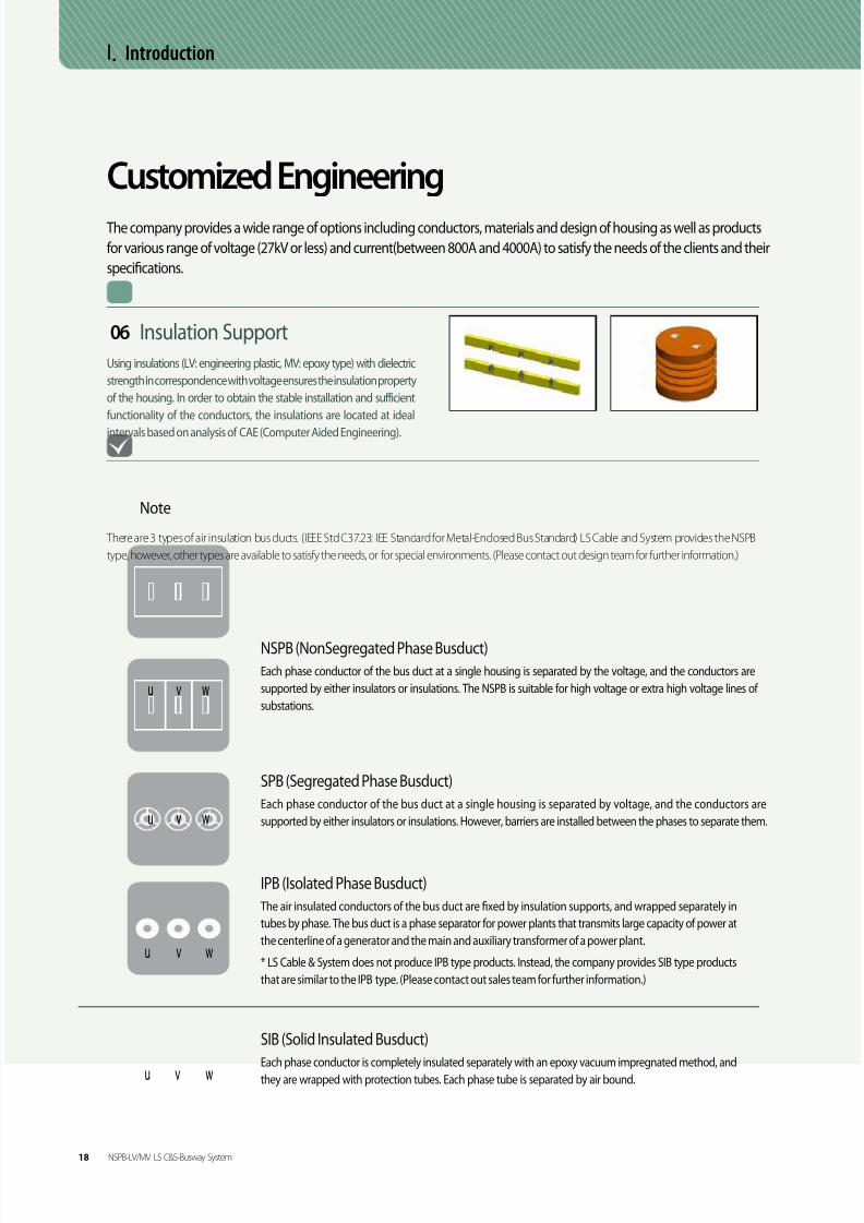
8/9/2019 Catalogo LSC_BUS_en_ÅëÇÕ
http://slidepdf.com/reader/full/catalogo-lscbusenaeco 104/184

8/9/2019 Catalogo LSC_BUS_en_ÅëÇÕ
http://slidepdf.com/reader/full/catalogo-lscbusenaeco 105/184

8/9/2019 Catalogo LSC_BUS_en_ÅëÇÕ
http://slidepdf.com/reader/full/catalogo-lscbusenaeco 106/184
Ⅱ. General Data
NSPB-LV
ContentsII. General Data 21
III. Component
- Feeder 22
- Fittings 23- Hanger 24

8/9/2019 Catalogo LSC_BUS_en_ÅëÇÕ
http://slidepdf.com/reader/full/catalogo-lscbusenaeco 107/184
06 / 07Ⅱ. General Data
Basic StructureThe NSPB-LV uses epoxy insulating material (thermal class 130 C) to separate the phases, and secure them using high
strength engineering plastic. It can be applied to 1000V or less, or between 800A and 4000A.
Note
The NSPB is a hybrid type bus duct that combined the benefits of the epoxy insulation type and the air insulation type. Although it provides better
insulation stability, it is larger and the cost is higher than the E-Series (sandwich type). Therefore, they are suitable for large plants where the stability
is priority.
Structure
Sectional View
• Supporting Insulater
• Al / STS / SPCC
• CU or AL
Joint Cover
Indoor Outdoor
• Joint Cover
• Final Cover
• Joint Cover
G em er a l D a t a
NSPB-LV/MV LS C&S-Busway System 21

8/9/2019 Catalogo LSC_BUS_en_ÅëÇÕ
http://slidepdf.com/reader/full/catalogo-lscbusenaeco 108/184
* Since the standards of the conductors differ, these are only for reference, and they
can be adjusted according to the installation site, or on request.
(For using aluminum conductors, please contact our design team for further information.)
Ⅲ. Component
FeederAlthough the standard length of the LS C&S NSPB-LV Bus Duct is 2 meters, it can be adjusted to the installation environment
and on request.
Flanged EndThe flanged end is used at a transformer or at a low-tension panel.
(Please, contact our design team for further information.)
A
NL-1-1 NL-1-2
A
BB
t
w
w
t
Ampere(A)Dimension (mm) Earth bar
(mm)Fig.
t W A B
CU
630 6 70 572 320
6.35*41NL-1-1
800 6 70 572 320
1,000 6 70 572 320
1,250 6 95 572 345
1,600 10 95 590 345
2,000 10 135 590 385
2,500 12 170 590 420
3,200 12 240 590 490
4,000 12 200 800 500 NL-1-2
22 NSPB-LV/MV LS C&S-Busway System

8/9/2019 Catalogo LSC_BUS_en_ÅëÇÕ
http://slidepdf.com/reader/full/catalogo-lscbusenaeco 109/184
06 / 07
Fittings
Elbow[Vertical] [Horizontal]
Offset[Vertical] [Horizontal]
Tee[Vertical] [Horizontal]
LS C&S NSPB has a wide range of fittings to satisfy any layout of buildings. Elbow angles other than ninety degrees are also
available. Offsets or tees can be applied where the standard elbows are not feasible. (Please contact our design team for
detailed information about the product length.)
C om p on en t
NSPB-LV/MV LS C&S-Busway System 23

8/9/2019 Catalogo LSC_BUS_en_ÅëÇÕ
http://slidepdf.com/reader/full/catalogo-lscbusenaeco 110/184

8/9/2019 Catalogo LSC_BUS_en_ÅëÇÕ
http://slidepdf.com/reader/full/catalogo-lscbusenaeco 111/184
06 / 07
NSPB-MV
ContentsII. General Data 26
III. Component
- Feeder 28
- Fittings 30- Flanged End 32
- Hanger 33

8/9/2019 Catalogo LSC_BUS_en_ÅëÇÕ
http://slidepdf.com/reader/full/catalogo-lscbusenaeco 112/184
Ⅱ. General Data
Basic StructureThe NSPB-MV uses epoxy insulating material (thermal class 130 C) to separate the phases, and secure them using high strength
epoxy. It can be applied to 1000V or less, or between 800A and 4000A.
Sectional View
Sectional View
Structure (Vertical)
• Supporting Insulater
• Al / STS / SPCC
• Copper or Aluminum
Structure (Horizontal)
• Supporting Insulater
• Al / STS / SPCC
• Copper or Aluminum
26 NSPB-LV/MV LS C&S-Busway System

8/9/2019 Catalogo LSC_BUS_en_ÅëÇÕ
http://slidepdf.com/reader/full/catalogo-lscbusenaeco 113/184
06 / 07
도체 절연 및 접속
Joint Covers
Indoor
• Joint Cover
Outdoor
• Joint Cover
• Final Cover
The conductors come with standard epoxy coating insulation. Tube insulation is also available on request. Use joint plates
to connect the parts, and cover them with boots as shown in the image below.
For indoor installation, applying joint covers are sufficient; however, for outdoor installation, final covers should be applied additionally on top
of the joint covers. (Please contact our design team for further information.)
G em er a l D a t a
NSPB-LV/MV LS C&S-Busway System 27

8/9/2019 Catalogo LSC_BUS_en_ÅëÇÕ
http://slidepdf.com/reader/full/catalogo-lscbusenaeco 114/184
Ⅲ. Component
Feeder (Alignment of the Conductors : Vertical)
Ampere(A) Dimension (mm) Earth bar
[mm]Fig.
t W A B
CU
800 6 70 572 320
6.35*41 NM1-1
1000 6 70 572 320
1250 6 95 572 345
1600 10 95 590 345
2000 10 135 590 385
2500 12 170 590 420
3200 12 240 590 490
4000 12 200 800 500 NM1-2
Ampere(A) Dimension (mm) Earth bar
[mm]Fig.
t W A B
CU
800 6 65 632 315
6.35*41 NM1-1
1000 6 65 632 315
1250 6 75 632 325
1600 10 80 650 330
2000 10 115 650 365
2500 12 145 650 395
3200 12 200 632 450
4000 12 180 860 480 NM1-2
Ampere(A) Dimension (mm) Earth bar
[mm]Fig.
t W A B
CU
800 6 65 692 315
6.35*41 NM1-1
1000 6 65 692 315
1250 6 70 692 320
1600 10 75 710 325
2000 10 105 710 355
2500 12 125 710 375
3200 12 180 710 430
4000 12 165 920 465 NM1-2
~ 4.76kV (IEC : ~7.2kV)
~ 15kV (IEC : ~12kV)
~ 27kV (IEC : ~24kV)
The standards of the conductors are only for reference, and they can be adjusted according to the installation environment,
or on request. (For using aluminum conductors, please contact our design team for further information.)
28 NSPB-LV/MV LS C&S-Busway System

8/9/2019 Catalogo LSC_BUS_en_ÅëÇÕ
http://slidepdf.com/reader/full/catalogo-lscbusenaeco 115/184

8/9/2019 Catalogo LSC_BUS_en_ÅëÇÕ
http://slidepdf.com/reader/full/catalogo-lscbusenaeco 116/184
Ⅲ. Component
Fittings
LS C&S NSPB has a wide range of fittings to satisfy any layout of buildings. Elbow angles other than ninety degrees are also
available. Offsets or tees can be applied where the standard elbows are not feasible. (Please contact our design team for
detailed information about the product size.)
Elbow (Alignment of the Conductors : Vertical)
Vertical Horizontal
Offset (Alignment of the Conductors : Vertical)
Vertical Horizontal
Tee (Alignment of the Conductors : Vertical)
Vertical Tee Horizontal Tee
30 NSPB-LV/MV LS C&S-Busway System

8/9/2019 Catalogo LSC_BUS_en_ÅëÇÕ
http://slidepdf.com/reader/full/catalogo-lscbusenaeco 117/184
06 / 07
Vertical Tee Horizontal Tee
Vertical Horizontal
Elbow (Alignment of the Conductors: Vertical)
Vertical Horizontal
Offset (Alignment of the Conductors : Vertical)
Tee (Alignment of the Conductors : Vertical)
C om p on en t
NSPB-LV/MV LS C&S-Busway System 31

8/9/2019 Catalogo LSC_BUS_en_ÅëÇÕ
http://slidepdf.com/reader/full/catalogo-lscbusenaeco 118/184
Vertically Aligned
Horizontally Aligned
Flanged EndThe flanged end is used at a transformer or at a low-tension panel.
(Please, contact our design team for further information including the size and capacity.)
Ⅲ. Component
32 NSPB-LV/MV LS C&S-Busway System

8/9/2019 Catalogo LSC_BUS_en_ÅëÇÕ
http://slidepdf.com/reader/full/catalogo-lscbusenaeco 119/184

8/9/2019 Catalogo LSC_BUS_en_ÅëÇÕ
http://slidepdf.com/reader/full/catalogo-lscbusenaeco 120/184
Ⅳ. Technical Data
Technical Data
* The numbers shown in the parenthesis of the short circuit current is the value of reinforcement products (optional).
Rated Max.voltage(kVrms)
Power frequencywithstand voltage
(kVrms), 60Hz
Impulse withstand1.2x50μs(kVpeak )
0.635 and 4.76 19 60
15 36 95
27 60 125
Rated continuoscurrent (A)
Short-circuit withstand current
(kArms), 2sec. (kApeak )
800~1000 40(50) 104(130)
1250~2000
2500~4000 50(65) 130(170)
The short circuit strength of the LS C&S NSPB can be adjusted and produced in accordance with the request and
specifics of the clients.
34 NSPB-LV/MV LS C&S-Busway System

8/9/2019 Catalogo LSC_BUS_en_ÅëÇÕ
http://slidepdf.com/reader/full/catalogo-lscbusenaeco 121/184
06 / 07Ⅴ. Install Information
The Joint of NSPB-LV and MV
[NSPB-LV] [NSPB-MV]
• The bus ducts should be aligned at the top and the bottom and the left and the right as well as horizontally and vertically.
Make sure that the surface is clear of dust before connecting them.
• Connect the bus ducts by using joint plates and HT bolts as shown in the image. Tighten the bolts until the eye-marking is visible.
• Once they are connected, check for gaps between the bus bars and the joint plates using a feeler gauge.
STEP 1.
• Apply the top and bottom joint covers,and tighten the bolts securely.
• For the NSPB-MV, apply boots additionally after
joint plates have been connected as shown in
the image.
[NSPB - LV] [NSPB - MV]
STEP 2.
Indoor Type Outdoor Type
Silicone Application
STEP 3.
• For outdoor installation, apply the top and bottom joint cover and reinforcement covers.
Apply silicone at both sides of the covers as shown in the image. (Torque = 120 kgf·cm)
T e c h ni c a
l D a t a
I n t a l l
I nf or m a t i on
NSPB-LV/MV LS C&S-Busway System 35

8/9/2019 Catalogo LSC_BUS_en_ÅëÇÕ
http://slidepdf.com/reader/full/catalogo-lscbusenaeco 122/184

8/9/2019 Catalogo LSC_BUS_en_ÅëÇÕ
http://slidepdf.com/reader/full/catalogo-lscbusenaeco 123/184
06 / 07
Busduct Major References
Korea Gas Corporation Substation 21 in Pyeongtaek
Investor : Korea Gas Corporation
Construction Period : 2010
Steel-making plant and sintering plant of Hyundai SteelCo., Ltd.
Investor : Samsung Engineering
Construction Period : 2008
JURONG AROMATIC COMPLEX
Investor : ABB, Singapore
Construction Period : 2012~2013
LG Chem Ltd. Yeosu Plant LDPE
Investor : LGChem Ltd.
Construction Period : 2011
RAS LAFFAN PROJECT PHASE 6 & 7Onshore LNG Plant
Investor : Qatar
Construction Period : 2006 ~ 2007 Completed
AKG2 (AL-KHALEEJ GAS) PROJECT PHASE IIOnshore GAS Plant
Investor : Qatar
Construction Period : 2007 ~ 2008
VII. Busduct Major References
C er t i fi c a t i on &
S p e c i fi c a t i on
B u s d u c
t M a j or
R ef er
en c e
NSPB-LV/MV LS C&S-Busway System 37

8/9/2019 Catalogo LSC_BUS_en_ÅëÇÕ
http://slidepdf.com/reader/full/catalogo-lscbusenaeco 124/184
06 / 07
Memo
C er t i fi c a t i on
&
S p e c i fi c a t i on
MS/Windway LS C&S-Busway System 33

8/9/2019 Catalogo LSC_BUS_en_ÅëÇÕ
http://slidepdf.com/reader/full/catalogo-lscbusenaeco 125/184

8/9/2019 Catalogo LSC_BUS_en_ÅëÇÕ
http://slidepdf.com/reader/full/catalogo-lscbusenaeco 126/184
I. Introduction
The LS C&S CR-Way is available from a low voltage of AC 1000V or less, up to a high voltage of 27kV. It is suitable for current capacities between 630A
to 7500A (high voltage product 120~5000A). The epoxy resin molding performs as insulation and housing with an IP68 rating. The CR-Way is suitable
for plants and factories where large capacity of power is required. It is an ideal distribution wiring system for outdoors, humid and dusty areas and any
place where chemicals are frequently used.
The epoxy insulation of the CR-Way is highly resistant to erosionand corrosion. Additional housing can be applied to maximize
Anticorrosion
The CR-Way
The CR-Way comes with a standard IP68 rating, and is protected
completely against water and particles. It is safe to use in an inadequate
environment.
Waterproof
The CR-Way comes with fire resistance efficiency as a standard feature,
and it is designed to prevent flames from spreading.
Fireproof
The CR-Way is designed to be completely molded by insulation, and
this design ensures safety use of the product near inflammable steam
and gas, and dusty environment with an explosive atmosphere.
Explosion Proof
Overview
14 CR-LV/MV LS C&S-Busway System

8/9/2019 Catalogo LSC_BUS_en_ÅëÇÕ
http://slidepdf.com/reader/full/catalogo-lscbusenaeco 127/184
06 / 07
Application
• Can be applied where salt concentration is
high including sea water
• Electrical room on a ship
Ships
• Guaranteed to provide stable supply of power in an extreme
environment of dust and other foreign substances
• Exposing the installation environment increases stability
for the user
• No possibility of getting damaged or destroyed.
Underground Utility Tunnels
• Suitable for indoor and outdoor installation,
and areas where high degree of protection is required
• Petrochemical plants
Plants & Factories
I n t r o d u c t i on
CR-LV/MV LS C&S-Busway System 15

8/9/2019 Catalogo LSC_BUS_en_ÅëÇÕ
http://slidepdf.com/reader/full/catalogo-lscbusenaeco 128/184
The cross-section areas of the conductor and housing
profile are designed to meet the standard permissible
operating temperature of IEC 61439-2, 6 (LV), and
IEC62271 (MV). Therefore the temperature rise limit of
the housing is within LV-55K or less, and MV-50K or less
of the ambient temperature.
Permissible Operating Temperature
• Ambient Temperature: -15° C to 55° C
• Relative Humidity: 95% or below(When the service condition of the environment does
meet the requirements listed above, please contact our
design team.)
Service Condition
Standard
Thanks to the epoxy resin molding, the CR-Way
comes with a standard IP68 rating. The product is
completely protected against water and particles,
and highly resistant to erosion and corrosion.
High Degree of Protection
The CR-Way has acquired an RoHS certification, and only
uses components without hazardous substances such as
lead, cadmium, mercury, chrome, PBBs and PBDEs.
Environmentally Friendly
Ⅱ. General Data
The CR-Way is designed to be completely molded by
insulation. This design provides explosion resistance as
well as excellent fire resistance capacity by preventing
flames from spreading.
Excellent Stability
Elbow
CR - MV
CR - LV
CR - MV
Offset
• IEC 61439-2 [(previous standard)IEC 60439-1]
Low-voltage Swichgear & Controlgear Asseblies
• IEC 61439-6 [(previous standard)IEC 60439-2]
Busbar Trunking Systems
• IEC 62271- Part 201
AC insulation-enclosed switchgear and
controlgear for rated voltages above 1kV
and up to and including 52kV
CR
LV
CR
MV
16 CR-LV/MV LS C&S-Busway System
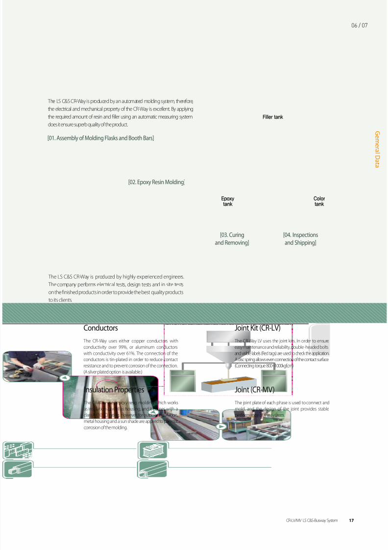
8/9/2019 Catalogo LSC_BUS_en_ÅëÇÕ
http://slidepdf.com/reader/full/catalogo-lscbusenaeco 129/184
06 / 07
The CR-Way uses either copper conductors with
conductivity over 99%, or aluminum conductors
with conductivity over 61%. The connection of the
conductors is tin-plated in order to reduce contact
resistance and to prevent corrosion of the connection.
(A silver plated option is available.)
Conductors
The CR-Way LV uses the joint kits. In order to ensure
easy maintenance and reliability, double -headed bolts
and visible labels (Red tags) are used to check the application.
A disc spring allows even connection of the contact surface.
(Connecting torque 800~1000kgf.cm)
Joint Kit (CR-LV)
The CR-Way uses epoxy resin molding which works
as insulation as well as housing, and it comes with a
class A (105C) rating. However, for outdoor installation,
metal housing and a sun shade are applied to prevent
corrosion of the molding.
Insulation Properties Joint (CR-MV)
The joint plate of each phase is used to connect and
mold, and the design of the joint provides stable
performance of the system.
The LS C&S CR-Way is produced by highly experienced engineers.
The company performs electrical tests, design tests and in site tests
on the finished products in order to provide the best quality products
to its clients.
[01. Assembly of Molding Flasks and Booth Bars]
[04. Inspections
and Shipping]
[02. Epoxy Resin Molding]
[03. Curing
and Removing]
The LS C&S CR-Way is produced by an automated molding system, therefore,
the electrical and mechanical property of the CR-Way is excellent. By applying
the required amount of resin and filler using an automatic measuring system
does it ensure superb quality of the product.
Epoxytank
Colortank
Filler tank
G em er a l D a t a
CR-LV/MV LS C&S-Busway System 17

8/9/2019 Catalogo LSC_BUS_en_ÅëÇÕ
http://slidepdf.com/reader/full/catalogo-lscbusenaeco 130/184
Ⅱ. General Data
IP 6 8Solid Particle Protection Liquid Ingress Protection
1m
15cm min.
1m
No Protection
1
2
3
4
5
6
5
6
7
8
0
1
2
3
4
0
Protection against 50mmdiameter solid particles.(back of a hand)
Protection against dust.
Protected againstfalling drops of water.
Protected againstlow pressure jets of waterfrom all directions.
Protected against
strong jets of waterfrom all directions.
Protected against the effectsof immersion between15.0 centimeters and 1.0 meter.
Protected againstlonger periods of immersionunder pressure.
Protected against falling
drops of water with anenclosure tilted at a 15degreeangle from a vertical line
Protected againstspray sat a 60degreeangle from a vertical line
Protected againstwater splashed fromall directions.Complete protection
against dust.
Protection against 12mmsolid particles. (fingers)
Protection against 2.4mmsolid particles.(tools or thick wires)
Protection against 1mmsolid particles.(tools or most wires)
No Protection
IP Code (Degree of Protection)IP Code is an international protection degree code provided by IEC 60529(Degree of Protection Provided by Enclosure-IP Code)
NEMA STANDARD: • IP54=NEMA 12, 12K, 13 • IP55=NEMA 3, 3X, 3S, 3SX • IP66=NEMA 4.4X • IP67=NEMA 6
* As the standard differs, it is a similar substitution, nota 1:1 substitution.
The standard feature of the CR-Way comes with a standard IP68 rating. The CR-Way is suitable for humid and dustyareas, chemical plants and areas where condensation may occur (exposed section between indoors and outdoors).
18 CR-LV/MV LS C&S-Busway System

8/9/2019 Catalogo LSC_BUS_en_ÅëÇÕ
http://slidepdf.com/reader/full/catalogo-lscbusenaeco 131/184

8/9/2019 Catalogo LSC_BUS_en_ÅëÇÕ
http://slidepdf.com/reader/full/catalogo-lscbusenaeco 132/184
Ⅱ. General Data
Configration
Indoor Type
[3 conductor] [4 conductor] [5 conductor]
Outdoor Type (sun exposure)[
Basic StructureThe CR-LV consists of conductors and epoxy resin. Since the resin performs as insulation and housing which provides protec-
tion to the interior structure, additional bus ducts or housing are not necessary.
For outdoor installation (sun exposure), a sun shade is used to prevent the epoxy resin from being exposed to direct sunlight.
• Sunshade(steel)
While other bus ducts with metal housing require grounding, the CR-LV does not require additional grounding because the epoxy resin insulation
itself performs as housing. (Additional grounding is available on request. Please contact our design team for further information.)
R R R S S ST T TN/E N/E N/E
]
20 CR-LV/MV LS C&S-Busway System

8/9/2019 Catalogo LSC_BUS_en_ÅëÇÕ
http://slidepdf.com/reader/full/catalogo-lscbusenaeco 133/184
06 / 07
Double-headed bolts are used to ensure a proper torque level when installing
the joint kit. If a torque wrench applies a pressure of 800 to 1000kgf·cm to the
outer bolt head, the head of the outer bolt and the tag attached to it will break
off on its own. Thus, it allows easy inspection for the proper application of the
bolts at the connection.
Double Head Bolts
Both joint plates of the joint kit and the conductors are tin plated. (A silver
plated option is available.) It prevents discoloration and corrosion of the joint
plates. In order to ensure easy maintenance and reliability, double -headed
bolts and visible labels are used to check the application, and a disc spring
allows an even connection of the contact surface.
Feature
The CR-Way uses a joint kit method.
!
Joint Kit
Precaution
Be sure to clean the interior of the connections prior to installation. Use caution not to twist the joint kit while inserting it, and after it is inserted.
An excessive pressure during installation may break the kit. Make sure that the double-headed bolts and the red tags are intact.
If a proper torque is not applied at the connection, it may cause heat during operation.
The number of double-headed
Number of DH bolts 1 2 3 4 6
630, 800, 1000,1250, 1600, 2000
CUAmpere
(A)AL
2500, 3200,3600, 4000
5000 6300 7500
630, 800,
1000, 1250
1600,
2000, 2500 -
3200,
3600, 4000 5000, 6300
G em er a l D a t a
CR-LV/MV LS C&S-Busway System 21

8/9/2019 Catalogo LSC_BUS_en_ÅëÇÕ
http://slidepdf.com/reader/full/catalogo-lscbusenaeco 134/184
Ⅲ. Component
FeederAlthough the standard length of the LS C&S CR-LV Bus Duct feeder is 3 meters, it can be adjusted to the installation
environment, or on request.
[Fig. CL1-3]
B
t
W A
B B
W A
140
2B+140
[Fig. CL1-2] [Fig. CL1-2]
B
3B+280
B
W A
140B 140
Ampere(A)Dimension(mm) Weight(kg/m)
Fig.t W A 3W 4W 4W+50%E 4W+100%E
AL
630
6.35
41 78 21.3 23.7 23.2 23.3
CL1-1
800 65 102 26.7 30.4 29.5 29.6
1000 86 123 32.4 37.8 36.3 36.4
1250 108 145 38.5 42.7 42.7 42.6
1600 164 201 53.5 59.4 59.3 59.4
2000 210 247 65.7 72.9 72.8 71.9
2500 126 163 85.2 99.4 95.1 97.4
3200 164 201 106.3 118 118 118.4
CL1-23600 184 221 116.4 129.7 129.6 130.1
4000 210 247 124.7 138.6 139 139.3
5000 184 221 182.8 193.2 193.4 189.1
6300 210 247 192.6 214.8 215.3 214.4CL1-3
CU
630
6.35
41 78 26.5 30.1 30.9 31.8
800 41 78 26.5 30.1 30.9 31.8
CL1-1
1000 57 94 32.2 37.3 38.9 39.6
1250 73 110 38.3 44.6 46.4 47.7
1600 108 145 51.7 60.4 62.5 64.8
2000 145 182 66.3 77.5 80.2 83.4
2500 195 232 85.7 100.3 104.2 108.4
3200 108 145 104.6 122.9 127.8 131.8
CL1-23600 126 163 118.6 139.5 145 151.4
4000 145 182 134.8 158.3 164.6 170.4
5000 195 232 173.5 203.9 214 220.56300 164 201 204.3 241.5 252.3 260
CL1-37500 195 232 261.2 309 324.1 334.5
* B : 3WGE=90mm, 4WGE/4WHE/4WFE=100mm
22 CR-LV/MV LS C&S-Busway System

8/9/2019 Catalogo LSC_BUS_en_ÅëÇÕ
http://slidepdf.com/reader/full/catalogo-lscbusenaeco 135/184
06 / 07
Flanged EndThe flanged end is connected to either a transformer or a
panel. Dimension details are shown below.
Ampere(A) Dimension (mm) Fig.t W A B
AL
630
6.35
41 ~
100
CL2-2800 62 ~
1,000 86 40CL2-3
1,250 108 50
1,600 164 60CL2-5
2,000 210 70
2,500 (2)126 40
130
CL2-4
3,200 (2)164 60
CL2-5
3,600 (2)184 60
4,000 (2)210 70
5,000 (3)184 60
6,300 (3)210 70
CU
630
6.35
41 ~
100
CL2-2800 41 ~
1,000 57 ~
1,250 73 40CL2-3
1,600 108 50
2,000 145 50 CL2-4
2,500 195 70 CL2-5
3,200 (2)108 50
130
CL2-3
3,600 (2)126 40CL2-4
4,000 (2)145 505,000 (2)195 70 CL2-5
6,300 (3)164 60 CL2-5
7,500 (3)195 70 CL2-5
[Fig. CL2-1]
[Fig. CL2-2] [Fig. CL2-3] [Fig. CL2-4] [Fig. CL2-5]
C om p on en t
CR-LV/MV LS C&S-Busway System 23

8/9/2019 Catalogo LSC_BUS_en_ÅëÇÕ
http://slidepdf.com/reader/full/catalogo-lscbusenaeco 136/184
Elbow[Vertical] [Horizontal]
Offset[Vertical] [Horizontal]
Ⅲ. Component
XY
X
Y
Y
XZ
X
Z
Y
Ampere(A)Dimension(mm)
X Y
1 단 500 5002 단 500 500
3 단 500 500
Ampere(A)Dimension(mm)
X Y Y
1 단 500 150 500
2 단 500 150 5003 단 500 150 500
Ampere(A)Dimension(mm)
X Y Z
1 단 500 300 500
2 단 500 300 5003 단 500 300 500
Ampere(A)Dimension(mm)
X Y
1 단 500 5002 단 600 600
3 단 700 700
FittingsFittings including the elbow and tee are designed to adapt to any change made to the direction of the bus duct installation.
The same features have been applied to the fittings of the CR-Way, and the size specifications are shown below.
(The standard dimension of each fitting is the same as the dimension shown in the table below. Please contact our design
team for information about the minimum dimension.)
24 CR-LV/MV LS C&S-Busway System

8/9/2019 Catalogo LSC_BUS_en_ÅëÇÕ
http://slidepdf.com/reader/full/catalogo-lscbusenaeco 137/184
06 / 07
Expansion(optional)
Tee
Combination
[Vertical] [Horizontal]
X
Y
Z
X
Y
Z
Y
Z
X
Ampere(A)Dimension(mm)
X Y Z
1 단 500 300 500
2 단 600 400 6003 단 700 500 700
Ampere(A)Dimension(mm)
X Y Z
1 단 500 500 5002 단 500 500 500
3 단 500 500 500
Ampere(A)Dimension(mm)
X Y Z
1 단 500 500 500
C om p on en t
CR-LV/MV LS C&S-Busway System 25

8/9/2019 Catalogo LSC_BUS_en_ÅëÇÕ
http://slidepdf.com/reader/full/catalogo-lscbusenaeco 138/184

8/9/2019 Catalogo LSC_BUS_en_ÅëÇÕ
http://slidepdf.com/reader/full/catalogo-lscbusenaeco 139/184
06 / 07
Etc.Wall Flange Floor Opening
• W : The width of the product
• H : The height of the product
• W : The width of the product
• H : The height of the product
The required minimum distances from a wall for heat dissipation and maintenance
Wall opening sizeCut out
Floor opening sizeCut out
A wall flange is used to seal the gaps produced during
bus duct installation on the walls, ceilings and floors.
The company does not provide glass wool or fire forms.
C om p on en t
CR-LV/MV LS C&S-Busway System 27

8/9/2019 Catalogo LSC_BUS_en_ÅëÇÕ
http://slidepdf.com/reader/full/catalogo-lscbusenaeco 140/184
Ⅳ. Technical Data
The short circuit strength of the CL-LV has been tested as specified in IEC 61439-2, 6 [(previous standard) IEC 60439-1, 2], and certified by KEMA.
Short Circuit Strength
Ampere(A) 630 800 1000 1250 1600 2000 2500 3200 3600 4000 5000 6300 7500
AL1sec 40 40 50 50 50 80 80 80 100 100 100 130 1303sec 23 23 29 29 29 46 46 46 58 58 58 75 75
CU1sec 40 40 50 50 50 80 80 80 100 100 100 130 -3sec 23 23 29 29 29 46 46 46 58 58 58 75 -
Ampere(A)Impedancex10-3Ω(uΩ /100m,60Hz) Voltage Drop (V/100m)
R X Z 0.7 0.8 0.9 1
AL
630 14.72 7.11 16.34 16.78 17.50 17.83 16.06800 9.78 5.44 11.19 14.87 15.37 15.49 13.55
1000 7.14 4.30 8.34 13.98 14.37 14.38 12.371250 5.76 3.61 6.80 14.32 14.67 14.64 12.471600 3.92 2.57 4.69 12.70 12.98 12.89 10.872000 3.14 2.09 3.77 12.78 13.04 12.95 10.892500 2.68 1.78 3.21 13.60 13.88 13.78 11.583200 2.13 1.40 2.55 13.81 14.10 14.00 11.793600 1.58 1.26 2.03 12.54 12.63 12.32 9.884000 1.39 1.12 1.78 12.26 12.34 12.03 9.62
5000 1.06 0.87 1.36 11.75 11.81 11.49 9.146300 0.92 0.76 1.20 13.00 13.06 12.70 10.08
CU
630 8.57 7.11 11.14 12.09 12.14 11.80 9.35800 8.57 7.11 11.14 15.35 15.41 14.98 11.87
1000 6.42 5.77 8.63 14.91 14.88 14.36 11.111250 5.09 4.85 7.03 15.21 15.12 14.50 11.021600 3.56 3.61 5.07 14.06 13.90 13.25 9.872000 2.74 2.85 3.96 13.71 13.53 12.86 9.502500 2.12 2.22 3.07 13.30 13.12 12.46 9.183200 1.94 2.03 2.81 15.59 15.38 14.60 10.763600 1.70 1.78 2.46 15.34 15.14 14.38 10.614000 1.51 1.57 2.18 15.08 14.89 14.15 10.465000 0.88 1.20 1.48 12.72 12.30 11.35 7.606300 0.79 1.08 1.34 14.44 13.95 12.87 8.587500 0.58 0.82 1.01 12.91 12.45 11.47 7.59
Technical DataImpedance and Voltage Drop The formula to measure the voltage drop of a busduct is shown below. The impedance and voltage drop values for aluminum and
copper conductors are shown in the table below.
The values listed are measured between the upper and middle lines at 60Hz. For a 50Hz installation, multiply the reactance (X) by 0.83.
28 CR-LV/MV LS C&S-Busway System

8/9/2019 Catalogo LSC_BUS_en_ÅëÇÕ
http://slidepdf.com/reader/full/catalogo-lscbusenaeco 141/184
06 / 07
Classification 1 2 3 4 5 6 7 8 9
Censer Location Joint Conductor Exterior of Epoxy Ambient Temperature
Temperature Rise
Value69K 62K 65K 63K 52K 51K 44K 50K 21.4℃
80
70
60
50
40
30
20
10
0 1 2 3 4 5 6 7 8
5
6
7 8
1 2 3 4
T e m p e r a t u r e ( )
Time(hr)
- Joint -
1
2 3
4
5
6
9
7 8
The temperature rise limit is an important property which determines the performance of bus ducts. The temperature rise limit of the
bus duct is designed so that when a bus duct is operated with a rated current , the temperature limit values of the housing are within
55K as specified in IEC61439-2 and 6 [(previous standard) IEC 60439-1 and 2].
Temperature Rise
T e c h ni c a
l D a t a
CR-LV/MV LS C&S-Busway System 29

8/9/2019 Catalogo LSC_BUS_en_ÅëÇÕ
http://slidepdf.com/reader/full/catalogo-lscbusenaeco 142/184

8/9/2019 Catalogo LSC_BUS_en_ÅëÇÕ
http://slidepdf.com/reader/full/catalogo-lscbusenaeco 143/184
06 / 07
Be sure to keep the ambient temperature at 25°C or higher before mixing the epoxy resin and
filler. When mixing the epoxy resin in a cool environment, be sure to cover the mixing container
to keep warm. It is to maintain the temperature of the container at 25°C or higher. In order of
filler, epoxy resin and hardener, add them into the mixing container, and mix it for 15 minutes
using a hand drill. (Please contact our design team for information about how to maintain the
temperature of the container when mixing the epoxy resin in a cool environment.)
Check List
• The ambient temperature: 25° C or higher
• Mix filler, epoxy resin and hardener for 15 minutes
Pour the mixture into the molding flask. Maintain the ambient temperature at 25° C. When
molding in a cool environment, cover the molding flask to keep warm to maintain the
temperature at the molding flask. Remove foams on the surface of the mixture for about
1 hour. Mold only three joints out of a total of four, and continue molding the entire line
following the same procedure. Wait for 8 hours, and check the function of the insulation
by checking the insulation resistance. When it is normal, finish molding the remaining
joint. (Please contact our design team for information about covering the container when
molding the epoxy resin in a cool environment.)
Check List
• Ambient temperature: 25°C or higher
• Removing foams on the surface of the mixture for 1 hour
Remove the mixture form the molding flask, and polish the rough surface with
sandpaper.
Check List
• When to remove the molding flask: 8 hours after the molding
• Polishing the surface with sandpaper
Perform the final inspection to check the performance of the joint.
Check List
• Final inspection of the joint
5
6
7
8
I n t a l l
I nf or m a t i on
CR-LV/MV LS C&S-Busway System 31

8/9/2019 Catalogo LSC_BUS_en_ÅëÇÕ
http://slidepdf.com/reader/full/catalogo-lscbusenaeco 144/184
CR-MV LS전선 Busduct System Catalogue
06 of 08
II. General Data 33
III. Compenent
- Feeder 35
- Fittings 36
- Terminal 37
- Hanger 38
- Etc 39
IV. Technical Data - Impedence 40
- Voltage Drop 40
- Temperature Rise 41
V. Install Information 42
Contents

8/9/2019 Catalogo LSC_BUS_en_ÅëÇÕ
http://slidepdf.com/reader/full/catalogo-lscbusenaeco 145/184
06 / 07Ⅱ. General Data
[The Bus Duct with No Housing]
[The Bus Duct with Housing]
Basic StructureThe CR-MV is compact in comparison with the air insulated types. It is completely covered with epoxy insulation
molding and provides high stability. The CR-MV is designed for 27kV or less, and 1250A up to 5000A.
The standard IP68 rating of the CR-MV is suitable for the exposed section of both indoor and outdoor installation,
and inadequate environments including humid areas.
NoteEither aluminum or copper conductors will be applied. Housing will be applied for both outdoor types and the bus ducts over 10kV for grounding
and shielding.
Specifics Indoor Type Outdoor Type
7.2kV 이하 The Bus Duct with No Housing The Bus Duct with Housing
7.2kV 초과 The Bus Duct with Housing The Bus Duct with Housing
G em er a l D a t a
CR-LV/MV LS C&S-Busway System 33

8/9/2019 Catalogo LSC_BUS_en_ÅëÇÕ
http://slidepdf.com/reader/full/catalogo-lscbusenaeco 146/184
Ⅲ. Component
In addition to the regular, design and in-site test that the company performs
for all the products, the CM-MV has also been tested for partial discharge
tests to inspect the interior foams to provide stability.
Using mobile defoamers to remove foams from joint moldings at construction
sites provides quality as good as factory-manufactured moldings.
Regular test : Structure and visual inspection, dielectric test (AC),partial discharge test
Design test : Temperature rise test, short circuit test, requested testsby clients
In site test : Structure test, Insulation resistance test, dielectric test (DC)
Conductors CR-MV NSPB-MV
Insulation Type Epoxy Resin Molding Air Insulation
Installation Location Special Plant (chemical plants, humid areas) General plants
Features
• IP68
• Complete molding system provides safety at any environment
• Replacement and repair can be relatively difficult
• IP42, 54, 65
• The air inside of the housing can cause condensation
• Relatively easy repair and replacement
[NSPB-MV][CR-MV]
Basic StructureIn comparison with other NSPB type bus ducts for high voltage (27kV or less), the conductors and joints of the CR-MV
are completely molded with epoxy resin which provides a standard IP68 rating. The CR-MV is suitable for inadequate
environments including chemical plants, areas prone to flood, an exposed section of indoor and outdoor installation
and areas where condensation may occur.
34 CR-LV/MV LS C&S-Busway System

8/9/2019 Catalogo LSC_BUS_en_ÅëÇÕ
http://slidepdf.com/reader/full/catalogo-lscbusenaeco 147/184
06 / 07
FeederAlthough the standard length of the LS C&S CR-MV Bus Duct feeder is 3 meters, it can be adjusted to the installation
environment, or on request. The housing is only applied for indoor installation and products with 10kV or higher.
* Further discussion is required with our design team for product with 17.5kV or higher.
Ampere(A)Conductor
7.2kV 17.5kV
A B C Dweight (kg/m)
A B C Dweight
(kg/m)t W Indoor Outdoor
CU
1250 4
100
276
130
500
315
89 113
315
150
540
335
119
1600 6 98 122 1272000 8 103 127 132
2500 12 114 138 143
3200 10160 190 375
157 183210 395
199
3600 12 166 192 207
4000 10130 300 485
247 278320 505
286
5000 12 260 292 299
AL
1250 5100 130 315
83 107150 335
113
1600 9 86 110 115
2000 8160 190 375
87 111210 395
116
2500 12 89 113 118
3200 6
130 300 485
124 151
230 505
166
3600 8 126 152 167
4000 10 193 225 232
C om p on en t
CR-LV/MV LS C&S-Busway System 35
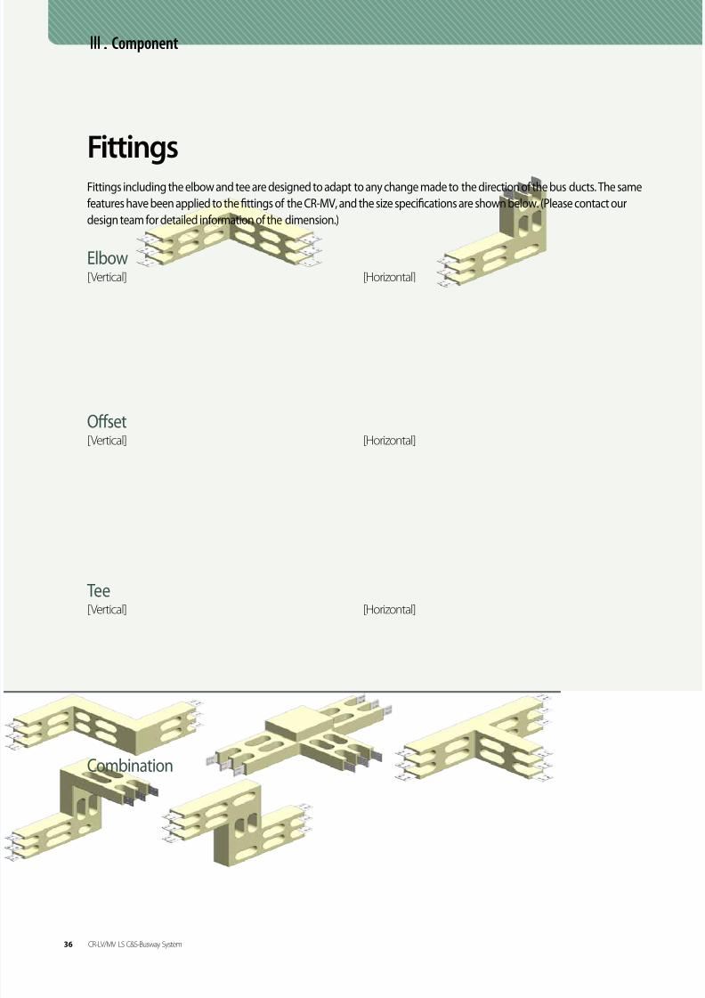
8/9/2019 Catalogo LSC_BUS_en_ÅëÇÕ
http://slidepdf.com/reader/full/catalogo-lscbusenaeco 148/184

8/9/2019 Catalogo LSC_BUS_en_ÅëÇÕ
http://slidepdf.com/reader/full/catalogo-lscbusenaeco 149/184
06 / 07
TerminalTerminals are connected to the transformers or low-tension panels. The types of products are shown below. (Please contact
our design team for detailed information of the dimension.)
[Type1]
[T ype3]
[Type5]
[Type2]
[Type4]
[Type6]
C om p on en t
CR-LV/MV LS C&S-Busway System 37

8/9/2019 Catalogo LSC_BUS_en_ÅëÇÕ
http://slidepdf.com/reader/full/catalogo-lscbusenaeco 150/184
Ⅲ. Component
HangersBoth horizontal and vertical hangers are available for the CR-MV depending on the installation environment.
The standard horizontal installation method of the CR-MV requires two supports for each product. The standard 3
meter bus ducts are designed to be installed at 1.5-meter intervals, and the space between the hangers should not
For vertical installation of The CR-MV, install the vertical hangers first, and fix the bus ducts on the hangers for
better support.
Hanger rod
Hanger clamp
Hanger bar
Horizontal
Vertical Hangers
38 CR-LV/MV LS C&S-Busway System

8/9/2019 Catalogo LSC_BUS_en_ÅëÇÕ
http://slidepdf.com/reader/full/catalogo-lscbusenaeco 151/184
06 / 07
The required minimum distances from a wall for heat
Wall opening size
Cut out
Floor opening size
Cut out
A wall flange is used to seal the gaps produced during installation
of bus ducts at the walls, ceilings and floors. The company does not
provide glass wool or fire forms.
Etc.Wall Flange Floor Opening
• W : The width of the product
• H : The height of the product
• W : The width of the product
• H : The height of the product
C om p on en t
CR-LV/MV LS C&S-Busway System 39

8/9/2019 Catalogo LSC_BUS_en_ÅëÇÕ
http://slidepdf.com/reader/full/catalogo-lscbusenaeco 152/184
Ⅳ. Technical Data
The short circuit strength of the CL-MV has been tested as specified inIEC 62271-Part 201.
Short Circuit Strength
Ampere(A)Impedancex10-3Ω(uΩ /100m,60Hz) Voltage Drop(V/100m)
R X Z 0.7 0.8 0.9 1
AL
1250 5.76 3.61 6.80 14.32 14.67 14.64 12.47
1600 3.92 2.57 4.69 12.70 12.98 12.89 10.87
2000 3.14 2.09 3.77 12.78 13.04 12.95 10.89
2500 2.68 1.78 3.21 13.60 13.88 13.78 11.58
3200 2.13 1.40 2.55 13.81 14.10 14.00 11.79
3600 1.58 1.26 2.03 12.54 12.63 12.32 9.88
4000 1.39 1.12 1.78 12.26 12.34 12.03 9.62
CU
1250 5.09 4.85 7.03 15.21 15.12 14.50 11.02
1600 3.56 3.61 5.07 14.06 13.90 13.25 9.87
2000 2.74 2.85 3.96 13.71 13.53 12.86 9.50
2500 2.12 2.22 3.07 13.30 13.12 12.46 9.18
3200 1.94 2.03 2.81 15.59 15.38 14.60 10.76
3600 1.70 1.78 2.46 15.34 15.14 14.38 10.61
4000 1.51 1.57 2.18 15.08 14.89 14.15 10.46
5000 0.88 1.20 1.48 12.72 12.30 11.35 7.60
Ampere(A) 1250 1600 2000 2500 3200 3600 4000 5000
AL
1sec 40 50 50 50 50 50 50
3sec 23 29 29 29 29 29 29
CU1sec 40 50 50 50 50 50 50 50
3sec 23 29 29 29 29 29 29 29
Impedance and Voltage Drop The formula to measure the voltage drop of a busduct is shown below. The impedance and voltage drop values for aluminum and copper
conductors are shown in the table below.
The values listed are measured between upper and middle lines at 60Hz. For a 50Hz installation, multiply the reactance (X) by 0.83.
Technical Data
40 CR-LV/MV LS C&S-Busway System

8/9/2019 Catalogo LSC_BUS_en_ÅëÇÕ
http://slidepdf.com/reader/full/catalogo-lscbusenaeco 153/184
06 / 07
Classification 1 2 3 4 5 6 7 8
Censer Location Joint Conductor HousingAmbient
Temperature
Temperature Rise
Value51K 54K 51K 35K 35K 43K 43K 27℃
41 2 3
- Joint -
80
70
60
50
40
30
20
10
0 1 2 3 4 5 6 7 8
T e m p e r a t u r e ( )
Time(hr)
1
2
3
4 5
6 7
8
5
6 7
The temperature rise limit is an important property which determines the performance of bus ducts. The temperature rise limit of the bus duct
is designed so that when a bus duct is operated with a rated current, the temperature limit values of the housing are within 50K as specified
in IEC62271-Part 201.
Temperature Rise
T e c h ni c a
l D a t a
CR-LV/MV LS C&S-Busway System 41

8/9/2019 Catalogo LSC_BUS_en_ÅëÇÕ
http://slidepdf.com/reader/full/catalogo-lscbusenaeco 154/184

8/9/2019 Catalogo LSC_BUS_en_ÅëÇÕ
http://slidepdf.com/reader/full/catalogo-lscbusenaeco 155/184
06 / 07
Vacuum Chamber
Be sure to keep the ambient temperature at 25°C or higher before mixing the mixture.
When mixing in a cool environment, be sure to cover the mixing container to keep warm.
It is to maintain the temperature of the container at 25°C or higher. In order of filler, epoxy
resin and hardener, add them into the mixing container, and mix it for 15 minutes using a
hand drill. Pour the mixture into the provided vacuum chamber, and whisk it for 30minutes
to remove foams.
Check List
• The ambient temperature: 25° C or higher
• Mix filler, epoxy resin and hardener for 15 minutes
• Using mobile vacuum chamber to remove foams
Pour the mixture into the molding flask. Maintain the ambient temperature at 25° C. When
molding in a cool environment, cover the molding flask to keep warm to maintain 25°C
at the molding flask. Remove foams on the surface of the mixture for about 1 hour. Mold
only three joints out of a total of four, and continue molding the entire line following the
same procedure. Wait for 8 hours, and check the function of the insulation by checking the
insulation resistance. When it is normal, finish molding the remaining joint.
Check List
• Ambient temperature: 25°C or higher
• Removing foams on the surface of the mixture for 1 hour
Remove the mixture form the molding flask, and polish the rough surface with sandpaper.
Check List
• When to remove the molding flask: 8 hours after molding
Perform the final inspection to check the performance of the joint.
5
6
7
8
I n t a l l
I nf or m a t i on
CR-LV/MV LS C&S-Busway System 43

8/9/2019 Catalogo LSC_BUS_en_ÅëÇÕ
http://slidepdf.com/reader/full/catalogo-lscbusenaeco 156/184
VI. Certification & Specification
Certification & Specification
Wall Opening Fireproof
Certification (CR-LV)
KEMA Certification (CR-MV)
Flame Resistance
Certification (CR-LV)
Structural Loading
Certification (CR-LV)
Short Circuit Test KERI
Certification (CR-LV)
Temperature Rise Test KERI
Certification(CR-LV)
Vibration Resistance
Certification (CR-LV)
Fireproof Certification (CR-LV)
KEMA Certification (CR-LV)
ISO9001 ISO14001 OHSAS18001
44 Certification & Specification CR-LV/MV LS전선-Busway System

8/9/2019 Catalogo LSC_BUS_en_ÅëÇÕ
http://slidepdf.com/reader/full/catalogo-lscbusenaeco 157/184
06 / 07
Busduct Major References
Base Oil ProductionAbudhabi, UAE, 2013 Will be completedInvestor : TakreerContractor : Hyundai EngineeringConstruction Period : 2011 ~ 2013
Ruwais Refinery ExpansionAbudhabi, UAE, 2012 completedInvestor : TakreerContractor : Samsung EngineeringConstruction Period : 2011 ~ 2013
Adamant Data CenterPetersburg, Russia, 2012 completedInvestor : ADAMANT GROUPContractor : ADAMANT GROUP Construction Period : 2011 ~ 2012
Borugh 3 XLPEAbudhabi, UAE,2012~2013 Will be completedInvestor : BorougeContractor : Hyundai Engineering & Construction
Construction Period : 2011 ~ 2013
Gyron Data CenterHemel Hempstead, UK,2012~2013 completed
Investor : GYRON INTERNET LTDContractor : GYRON INTERNET LTDConstruction Period : 2012 ~ 2013
Raganskiy LyadYekaterinburg, Russia, 2012 completedInvestor : TAGANSKIY LYAD LTD
Contractor : TAGANSKIY LYAD LTDConstruction Period : 2011 ~ 2012
VII. Busduct Major References
C er t i fi c a t i on &
S p e c i fi c a t i on
B u s d u c
t M a j or
R ef er
en c e
CR-LV/MV LS C&S-Busway System 45

8/9/2019 Catalogo LSC_BUS_en_ÅëÇÕ
http://slidepdf.com/reader/full/catalogo-lscbusenaeco 158/184
06 / 07
Memo
C er t i fi c a t i on
&
S p e c i fi c a t i on
MS/Windway LS C&S-Busway System 33

8/9/2019 Catalogo LSC_BUS_en_ÅëÇÕ
http://slidepdf.com/reader/full/catalogo-lscbusenaeco 159/184
ContentsI. Introduction- Overview 14
- Application 15
II. General Data 16
III. Component 18
IV. Design & Test 20
V. Install Information 22
VI. Certification & Specification 23
SIB (Solid Insulated Bus-system)LS전선 Busduct System Catalogue
07 of 08

8/9/2019 Catalogo LSC_BUS_en_ÅëÇÕ
http://slidepdf.com/reader/full/catalogo-lscbusenaeco 160/184
I. Introduction
Overview
Switchgear
Switchgear
Transformer
Transformer
TR Flanged End Box
TR Flanged End Box
Joint Con-
Fitting
Fitting
Feeder
Feeder
Joint Con-
Outdoor
Indoor (Electrical Room)
The LS C&S SIB (Solid Insulated Bus System) is a power distribution system with epoxy impregnated solid insulation. The SIB is an ideal product with the
benefits of bus ducts and cables combined. The SIB is suitable for high voltage (27kV or less) and high current (1000A to 7500A) by completely separating the
phases of the bus bars. By replacing the cables, the SIB provides space efficiency, and it also provides excellent short circuit strength and stability.
SIB
The company provides customized design to maximize the space efficiency for each installation site. Compared to cables, the
coiling area of the SIB is noticeably less, and the system does not require additional trays, therefore, the installation is much easier.
Economic and Easy Installation
The epoxy vacuum impregnation of the SIB provides highly stable electrical performance. Thanks to the completely separated
phases, it is completely free of short circuit between phases, and the system also comes with excellent short circuit strength.
Excellent Stability
The solid molding design of the SIB protects the system from accidents caused by condensation. Using an exterior flexible tube
and STS, the system is reliable against external impact and weather including light, wind, rain, moisture, and gas. It is suitable for
both the indoors and outdoors.
Superb Weather Resistance
The compact SIB can transmit larger capacity of power in comparison with the existing high voltage bus ducts.
The SIB uses only one bus bar for each phase to handle rated current sat up to 7500A, therefore, reducing inconveniency
of using several cables.
Large Capacity and Compact SizeR S T
14 SIB LS C&S-Busway System

8/9/2019 Catalogo LSC_BUS_en_ÅëÇÕ
http://slidepdf.com/reader/full/catalogo-lscbusenaeco 161/184

8/9/2019 Catalogo LSC_BUS_en_ÅëÇÕ
http://slidepdf.com/reader/full/catalogo-lscbusenaeco 162/184
General Data
The epoxy vacuum impregnation of the SIB provides
highly stable electrical performance. The completely
separated phases prevent any short circuits. The SIB is
perfectly safe from accidents caused by condensation
thanks to the completely molded bus duct design.
The SIB is partial discharge free, and can be usedsemi-permanently.
Maintenance Free
The SIB is designed to be safely used in inadequate
environments. The joint connections and the supports
of the SIB have been tested in actual wire routings
under severe service condition (class E10), and passed
the assessment of vibration fatigue.
Outstanding Durability
• IEC 60137
Insulated bushings for alternating voltages above 1000 V
Standard
The LS C&S Bus Ducts acquired RoHS certification, and only
uses components without hazardous substances such as
lead, cadmium, mercury, chrome, PBBs and PBDEs.
Environmentally Friendly
Ⅱ. General Data
The conductor size of the SIB has been designed tosatisfy the test methods and the standard permissible
operating temperature of IEC60137.
Permissible Operating Temperature
The system is very easy to install. By implementing flexible
bars, the expansion joint can be applied to the system.
Joint Connection
• Ambient Temperature: -15°~55° C
• Relative Humidity : 95% or below
(When the service condition of the environment does
not meet the requirements listed above, please contact
our design team.)
Service Condition
16 SIB LS C&S-Busway System

8/9/2019 Catalogo LSC_BUS_en_ÅëÇÕ
http://slidepdf.com/reader/full/catalogo-lscbusenaeco 163/184

8/9/2019 Catalogo LSC_BUS_en_ÅëÇÕ
http://slidepdf.com/reader/full/catalogo-lscbusenaeco 164/184

8/9/2019 Catalogo LSC_BUS_en_ÅëÇÕ
http://slidepdf.com/reader/full/catalogo-lscbusenaeco 165/184
06 / 07
Component
The maximum length of the feeder is 7 meters, and the
feeder is designed for 27kV or less, or up to 7000A.
Either aluminum or copper conductors are available.
Feeders
Thanks to aluminum compressive members, the
supports are very light, and the self assembly
structure design ensures easy installation.
Support
The SIB has a wide range of fittings to satisfy anylayout of buildings.
Terminals have been welded at both ends of the
SIB. The terminals are designed to be easily con-
nected to various equipments.
Single-Curve Type Double-Curve Type Double-Curve Type
Fittings
End Connectors (Gas, Oil and Air)
C om p on en t
SIB LS C&S-Busway System 19

8/9/2019 Catalogo LSC_BUS_en_ÅëÇÕ
http://slidepdf.com/reader/full/catalogo-lscbusenaeco 166/184

8/9/2019 Catalogo LSC_BUS_en_ÅëÇÕ
http://slidepdf.com/reader/full/catalogo-lscbusenaeco 167/184

8/9/2019 Catalogo LSC_BUS_en_ÅëÇÕ
http://slidepdf.com/reader/full/catalogo-lscbusenaeco 168/184
Joint Connection
Ⅴ. Install Information
STEP 1Check for any deformation or stain on the surface of the connectors.
Align them at the top and the bottom and the left and the right as
well as horizontally and vertically.
STEP 2Connect the provided flexible bars as shown in the image. In order to
maintain the electric field of the internal equipotential of the joint box,
connect the springs of the joint box with the connecting terminal.
(Please contact the design team for detailed instructions.)
STEP 3Push the joint box until it is positioned at the center to support the
joint box. Install clamps and connect the grounding.
STEP 4Install rubber bellows, and fix one of the bellows using STSties. Add
moisture absorbent through the other bellow before fastening it
with STS ties.
22 SIB LS C&S-Busway System

8/9/2019 Catalogo LSC_BUS_en_ÅëÇÕ
http://slidepdf.com/reader/full/catalogo-lscbusenaeco 169/184
06 / 07
ISO9001 ISO14001 OHSAS18001
Certification & Specification
KEMA CertificationTUV Eco Friendly Certification
VI. Certification & Specification
I n t al l
I nf or m a t i on
C er t i fi c a t i on &
S p e c i fi c a t i on
SIB LS C&S-Busway System 23

8/9/2019 Catalogo LSC_BUS_en_ÅëÇÕ
http://slidepdf.com/reader/full/catalogo-lscbusenaeco 170/184
Memo
24 SIB LS C&S-Busway System

8/9/2019 Catalogo LSC_BUS_en_ÅëÇÕ
http://slidepdf.com/reader/full/catalogo-lscbusenaeco 171/184
ContentsI. Introduction
- Overview 14
- Application 15
II. Component
- DTS 16- MPTS 19
- IR-Ts
22
BTMS(TemperatureMonitoring System)

8/9/2019 Catalogo LSC_BUS_en_ÅëÇÕ
http://slidepdf.com/reader/full/catalogo-lscbusenaeco 172/184
I. Introduction
The temperature sensors of the Bus Duct Temperature Monitoring System (BTMS) measure bus duct temperatures in real time to check the abnormality
of the lines to prevent accidents. Therefore, the BTMS is the optimum monitoring system for bus ducts.
About BTMS
BTMS Measuring Principles
Overview
The standard evaluation method to check the stability of the bus duct and other power distribution system is the evaluation of a permissible tempera-
ture and temperature change of the insulation materials. The permissible temperature is also used by international standards such as IEC to evaluate the
stability. Therefore, any abnormality of a product can be detected just by checking the temperature change.
Why BTMS?
BTMS Benefit
1) Easy Maintenance: Real time monitoring of the entire system including inaccessible areas
2) Unmanned Monitoring System: Minimize the size of the supervision staff for periodic inspection
Detect abnormalities if the temperature increases over the set value of the
standard temperature.
Ex. Set at 60° C : A pre-alarm will be set off at 50° C
An alarm will be set off at 60° C
01 Fixed Temperature Measurement
(Comparison to the Standard Temperature)Temperature(℃) Alarm
Distance(m)
Detect abnormality if the temperature increases over the set value of the
temperature during a certain period of time.
Ex. When the system is set for one minute, and the temperature variation is set
for 7°C, an alarm will be set off if the temperature increases over the set value
within the scheduled time period.
02 Differential Temperature Measurement(Comparison to Time and Temperature)
Temperature(℃)
Distance(m)
Alarm
▵T
Detect abnormalities based on temperature variations between one
measuring point and the other.
Ex. An alarm will be set off when the temperature of a measuring point ‘A’ is
higher than the temperatures of four locations before and after ‘A’.
03 Proportional Differential Temperature Measurement(Comparison to Temperature Variations)
Temperature(℃)
Distance(m)
Alarm
▵T
For bus ducts with two or more stacks, an alarm will be set off if the tempera-
ture differences of the stacks are higher than the set value.
Ex. A-stsck : 55℃, B-stack : 65℃
04 Proportional Measurement(Comparison to Temperature Differences)
Temperature(℃)
Distance(m)
▵TAlarm
14 BTMS LS C&S-Busway System

8/9/2019 Catalogo LSC_BUS_en_ÅëÇÕ
http://slidepdf.com/reader/full/catalogo-lscbusenaeco 173/184
06 / 07
• DTS (Optical Fiber Cable Sensor)
• MPTS (Digital Temperature Sensor)
Application
Feature DTS (Optical Fiber Cable Sensor) MPTS (Digital Temperature Sensor) IR-Ts (Infrared Temperature Sensor)
Monitoring
- Sequential temperatures
- Measure temperature by conducting
properties
- High-speed response
- Measure temperatures at multiple points
- Proximity measurement of the points
- Identify the variation using data log
- Measure temperature at a specific point
- Direct or proximity measurement
- High-speed response
Maximum
MeasurementSection
- Repeaterless measurement between1 to 12km.
- Measure temperatures at specific points only
(up to 80 points can be measured on a singleline).
- Measure a specific point only(single point for each line).
Economical
Efficiency
-Suitable for long-distance sensor installation.
-The cost of a measuring device is higher for
the optical fiber.
-Economical due to temperature sensors and
communication modules.
-Harness module
-Suitable for local or small-scale installation.
-The cost can be high, depending on the
sensor type.
Installation
and
Maintenance
- Maintenance for optical fiber cable routing is
required since optical attenuation can occur
when cable bends.
- Easy maintenance
- Connectors between the modules ensure
easy installation
- High-voltage line effect
- Additional repeaters and lines are
necessary when transmitting power
for multiple lines.
- Due to the single point for each line
system, high maintenance is required.
Application- Power Plant, Oil & Gas
- Display,반도체_Ex) Bus Duct선로
- Small-sized equipment facilities (electricalrooms)
- Ex. joint connection of bus ducts
- Ex. Distribution panel+
bus duct joint connections
S
SS
S
• IR-Ts (Infrared Temperature Sensor)
S
S
S
S
S
I n t r o d u c t i on
BTMS LS C&S-Busway System 15

8/9/2019 Catalogo LSC_BUS_en_ÅëÇÕ
http://slidepdf.com/reader/full/catalogo-lscbusenaeco 174/184
Ⅱ. Component
DTS
1) Optical fibers are used as the temperature sensor for the DTS.
• Compact and lig ht weight
• The DTS does not get affected by EMC and EMI.
• Economical
2) Measure and monitor temperature of long distance section.
3) A self-diagnosis system as well as an auto adjusting system for optical attenuation of optical fibers.
4) The DTS collects and manages the temperature data. The computer based system ensures easy management of HMI and data.
The distance of the point where the temperature has been measured is calculated using the process speed of the laser
pulse within the optical fibers.
x = c x t/2
Various back scattering laser lights return when the laser pulse has been discharged. One of the back scattering laser lights is
a Raman scattering light, and its wavelength change and scattering strength are used to measure the temperature.
las : The illumination level
of the anti-stoke light
la : The illumination level of
the stoke light
h : Planck constant
k : Boltzmann constant
c : The speed of light
v : Frequency of incident
light
T : Temperature
DTS Overview
Principles of Distance Measurement
Principles of Temperature Measurement
(Distributed Temperature System)
DTS
Laser
Fiber is the distributed sensor
Laser Pulse
Backscattered LightDetector
I s
kT I as
hav
∝ е( - )
DirectionalCoupler
Anti-Stokes Raman
Band
Stokes Raman
Band
Rayleigh Band
Raman Scattering Laser Light
Optical Fiber Sensor
Luminous
Source
Signal Processing
16 BTMS LS C&S-Busway System

8/9/2019 Catalogo LSC_BUS_en_ÅëÇÕ
http://slidepdf.com/reader/full/catalogo-lscbusenaeco 175/184
06 / 07
• DTS
− By channels (1,2,4,6ch) and distances (2,4,8,10,12km)
− Temperature sensing distance(1m) , Accuracy
• UPS (Optional)
− Provide stable power supply in case of power failure
− Protect power supply of computer equipment
and peripheral devices
• GUI
− Objective and convenient screen layout
− Self data backup and organization system
(data analysis-detect, manage and predict problems)
• Relay and Warning light
− Interlocked with the computer and can manage up to 8 signals
− Semi-permanent LED warning lights
Features of DTS
• Monitoring temperature profile: Temperature vs. Distance graph
• Monitoring by zones, lines and loads: Up to 500 pre-designated points and statistical information
• Auto detection and warning system (when bidirectional measurement was applied) of optical attenuation and fiber cut
• Warning system: Data prints based on real time temperature measurement
• Warning signals can be interlocked with other systems
(Ex. Interlocking with fire signal)
General Function
• Industrial Computer
− Stability of industrial PC
− Fast and stable monitoring and data management
− High capacity HDD with 1 terabyte
Monitoring PC
Optical Fiber
DTS
C om p on en t
BTMS LS C&S-Busway System 17

8/9/2019 Catalogo LSC_BUS_en_ÅëÇÕ
http://slidepdf.com/reader/full/catalogo-lscbusenaeco 176/184
Ⅱ. Component
[DTS Configuration Example] [Trend screen]
[GUI Configuration Example]
[SMS Transmission Screen]
DTS Application
18 BTMS LS C&S-Busway System

8/9/2019 Catalogo LSC_BUS_en_ÅëÇÕ
http://slidepdf.com/reader/full/catalogo-lscbusenaeco 177/184
06 / 07
Principles
The temperature is set by the size of the vibration energy of subtle displacement of atoms and molecules. The resistance values of metallic lines orsemiconductors change by temperature. An electromotive force can occur if the connecting point of dissimilar metals is heated. The digital temperature
sensor measures the resistance or the electromotive force to measure the temperature.
Feature
The system prints out measured temperature vales in digitalized signals. Therefore, data management is easier, and it also prevents degradation caused
by noise. The sensor is energy efficient, and suitable for measuring temperature in wide areas.
• The MPTS measures temperature of a specific point by installing a digital temperature sensor at a specific point including the joint
connection of a bus duct.
• Each sensor is linked to a communication system to transmit the measured temperature in real time.
• Up to 80 points can be linked to a single communication line.
• Temperature Sensor Module
- The current voltage characteristic changes in accordance with the temperature
variation at the P-N connecting point.
• Amplifier Circuit
- In order to amplify the weak signal of the sensor data, an amplifier circuit has been
installed in the sensor.
- Potential exterior noise during signal amplifications has been eliminated.
• Digital Converting Circuit
- Digitalized temperature value output
- Easy data management and prevention of the degradation caused by noise
Principles of the Digital Temperature Sensor
MPTS Preview
The Structure of the Temperature Sensor
Digital Temperature Sensor
MPTS
Temperature Sensor Module Amplifying Circuit Digital Converting Circuit
(Multi-Point Temperature System)
C om p on en t
BTMS LS C&S-Busway System 19

8/9/2019 Catalogo LSC_BUS_en_ÅëÇÕ
http://slidepdf.com/reader/full/catalogo-lscbusenaeco 178/184
Ⅱ. Component
MPTSThe data collected by the sensor is gathered and saved at the data collection system, and monitored by a surveillance PC.
Configuration
No. Specifics Feature
1 Sensor Module Digital temperature sensor module with communication function
2 Data Collection Device Collecting and transmitting of the temperature data of the sensor module
3 Power Supply Device Supply power using the sensor module
4 Monitoring PCMonitoring measure values through HMI
(data set-up, measuring, data log and information reference function)
MPTS Setup
1
2
3
4
20 BTMS LS C&S-Busway System

8/9/2019 Catalogo LSC_BUS_en_ÅëÇÕ
http://slidepdf.com/reader/full/catalogo-lscbusenaeco 179/184
06 / 07
• Main Screen
–Displays the temperature monitoring points
• Alarm Screen
–Displays the abnormalities, details and location
• Location Screen
–Displays the locations of the temperature monitoring points
• Trend Screen
- Displays the temperature variation trend
Drawing up a draft plane is easier thanks to the graphic configuration of HMI, and managing the points using the remote observation system
reduces the work loads.
MPTS Application
C om p on en t
BTMS LS C&S-Busway System 21

8/9/2019 Catalogo LSC_BUS_en_ÅëÇÕ
http://slidepdf.com/reader/full/catalogo-lscbusenaeco 180/184
Ⅱ. Component
IR-Ts
The IR-Ts uses an infrared light noncontact temperature sensor to
measure and monitor the heat released from objects. The system is
suitable for dangerous environments including high voltage areas, or
areas where contact sensors are not feasible.
IR-Ts : Infrared Camera
IR-Ts (CCTV)
: Infrared Camera + CCTV
1) Compact and light weight
2) Can be installed at all directions
3) Applicable Temperature Range: -20°C~ 200°C
4) Real time temperature variation measurement and video (CCTV Camera)
5) Wire or wireless communication network system
IR-Ts Preview
Feature
Installation(Exterior image of the distribution board)
Photographic Measuring
1) Infrared Camera(IR Cam) 2) CCTV 3) Composite photograph of IR+CCTV
22 BTMS LS C&S-Busway System

8/9/2019 Catalogo LSC_BUS_en_ÅëÇÕ
http://slidepdf.com/reader/full/catalogo-lscbusenaeco 181/184
06 / 07
IR-Ts Configuration
Temperature Sensors
- 16EA -
*
*
*
*
*
*
*
*
*
Data Collection Device
- PC-
C om p on en t
BTMS LS C&S-Busway System 23

8/9/2019 Catalogo LSC_BUS_en_ÅëÇÕ
http://slidepdf.com/reader/full/catalogo-lscbusenaeco 182/184
Houston Office22126 Manor Estates Dr. Katy, TX77449, USATel: +1-713-202-8003
Peru OfficeAv. Dos de mayo No.516 Oficina 307 Miraflores Lima 18 PeruTel : +51-1-221-9786
LSCWLS Industrial Park, Xin Mei Rd. National High-tech Industrial Development ZoneWuxi, Jiangsu Province 214028 ChinaTel : +86-510-8534-5943Production : Automotive Wire & Cable, Bus Duct, Electroncic Wire & Cable, Tube, ACF,Accessories for EHV Cable System
LSCTEast of Jing-jin Express, Yixingbu Entrance, Beichen Tianjin, ChinaTel : +86-22-2699-7618Production : Magnet Wire
China R&D Center(Yichang)#1 Tanjiahe Rd. Dianjun District, Yi-Chang City, Hubei Province 443004 ChinaTel. 070-8650-2188
LSHQ
#1 Tanjiahe Rd. Dianjun District, Yi-Chang City, Hubei Province 443004 China+86-717-667-7777Production : Power Cable, Submarine Cable, Industrial Specialty Cable
LS-VINA(Haiphong)South of Binh Bridge St. So Dau Precinct, Hong Bang Dt. Haiphong, VietnamTel. +84-31-540750Production : EHV Power Cable, ACSR, OPGW, SCR
Subsidiaries
Global Network
Sydney OfficeLevel 35, Suite 35.02 Northpoint 100 Miller St. North Sydney, NSW 2060 AustraliaTel. +61-2-9460-0255
Manila OfficeS-1903 B, West Tower, Philippine Stock Exchange Centre Exchange Rd.Ortigas Center, Pasig City, PhilippinesTel: +63-2-6875028
Jakarta OfficeGraha Mustika Ratu, 11th Fl. Jl.Jenderal Gatot Subroto Kav.74-75,Jakarta Selatan 12870 IndonesiaTel. +62-21-830-6733
Singapore Office300 Beach Rd. #25-07 The Concourse Singapore 199555Tel. +65-6342-9162~3
Abu Dhabi Office#133, Al Bateen Towers C6, Bainunah St.34, Al Bateen,P.O.Box 113 100, Abu Dhabi, U.A.ETel : +971-2-406-9856
Riyadh Office#7, 2nd Fl. Olaya St. B/D #28, Riyadh, Saudi ArabiaTel : +966-1-201-3515
Cairo Office#36, El-Zeini Tower, 25 Misr Helwan Rd. Maadi, Cairo, EgyptTel. +20-19-966-2810
Johannesburg Office3rd Fl. South Tower at Nelson Mandela Square,Corner 5th Ave. andMaude St. Sandton, Johannesburg, South AfricaTel. +27-11-783-6320
Moscow OfficePark Place Tower E711, 113/1 Leninsky Prospect, Moscow 117198 RussiaTel : +7-495-662-3811~14
Branches
LSCD (New Delhi, India)
Yichang, China

8/9/2019 Catalogo LSC_BUS_en_ÅëÇÕ
http://slidepdf.com/reader/full/catalogo-lscbusenaeco 183/184
LSCV(Hochiminh)Nhon Trach Il-Lockhang IZ, Nhon Trach Dt. Dong Nai province, Hochiminh, Vietnam
Tel. +84-61-356-9037Production : MV/LV Cable, Data Cable
LSCM(Penang)Lot 1192, Mukim 14, Permatang Tinggi, 1400 Bukit Mertajam, Penang, Malaysia
Tel. +60-4-588-9609(Ext.34)Production : Magent Wire
LSCI(Haryana)#101, 1st Fl. Park Center, Sector-30, Gurgaon, Haryana 122002. India
Tel : +91-124-4285800~4Production : RF Feeder Cable, Power Cable, OPGW
LSCD : Marketing and sales12th Fl. IFCI Tower 61 Nehru Place, 110019 New Delhi, IndiaTel : +91-4167-1588
LSCA : Marketing and sales6120 Powers Ferry Road, Atlanta, GA 30339, USATel. +1-770-657-6141
LSCU : Marketing and sales#109, Building 3, Chiswick Busuness Park 566 Chiswick High Rd.London, W4 5YA, UKTel. +44-20-8899-6671
LSCJ : Marketing and salesE 16th Fl. Akasaka Twin Tower 17-22, 2-Chome Akasaka, Minato-ku, JapanTel. +81-3-3582-9129
HeadquartersLS Tower, 1026-6 Hogye-dong, Dongan-gu, Anyang-si, Gyeonggi-do 431-830 Korea
Tel. +82-2-2189-9114
Anyang Plant
555 Hogye-dong, Dongan-gu, Anyang-si, Gyeonggi-do 431-830 KoreaTel. +82-31-428-4114Production : Automotive Wire, Tube Components, HV Cable & Connectors,Bus Duct, Flooring System
Gumi Plant190 Gongdan-dong, Gumi-si, Gyengsangbuk-do 730-708 KoreaTel. +82-54-469-7114Production : Power Cable up to 500kV, OHTL, OPGW, Data Cable,RF Feeder System, Copper Rod, Magnet Wire
Indong Plant643 Jinpyeong-dong, Gumi-si, Gyengsangbuk-do 730-735 KoreaTel. +82-54-469-7763Production : Industrial Cable & Module, Optical Cable, Aluminum Materials
Donghae Plant1377 Songjeong-dong, Donghae-si, Gangwon-do 240-806 KoreaTel. +82-33-820-3114Production : Submarine Cable, Industrial Specialty Cable
R&D Center200 Dangjeong-dong, Gunpo-si, Gyeonggi-do 431-831 KoreaTel : +82-31-450-8114
Korea Operations
LSCA (Atlanta, USA)

8/9/2019 Catalogo LSC_BUS_en_ÅëÇÕ
http://slidepdf.com/reader/full/catalogo-lscbusenaeco 184/184
,
.
i
O c
t .2 0 1 3


![Catalogo Catalogo Area Construccion2009[1]](https://static.documents.pub/doc/80x56/55cf9915550346d0339b76dc/catalogo-catalogo-area-construccion20091.jpg)

