94
CATALOGUE 1-2 | 2015 DRIVE CHAIN ATTACHMENT CHAIN

CATALOGUE 1-2 | 2015
DRIVE C
HA
IN / ATTAC
HM
ENT C
HA
INC
ATALO
GU
E 1-2
DRIVE CHAINATTACHMENT CHAIN
CATALOGUE 1-2 DRIVE CHAIN
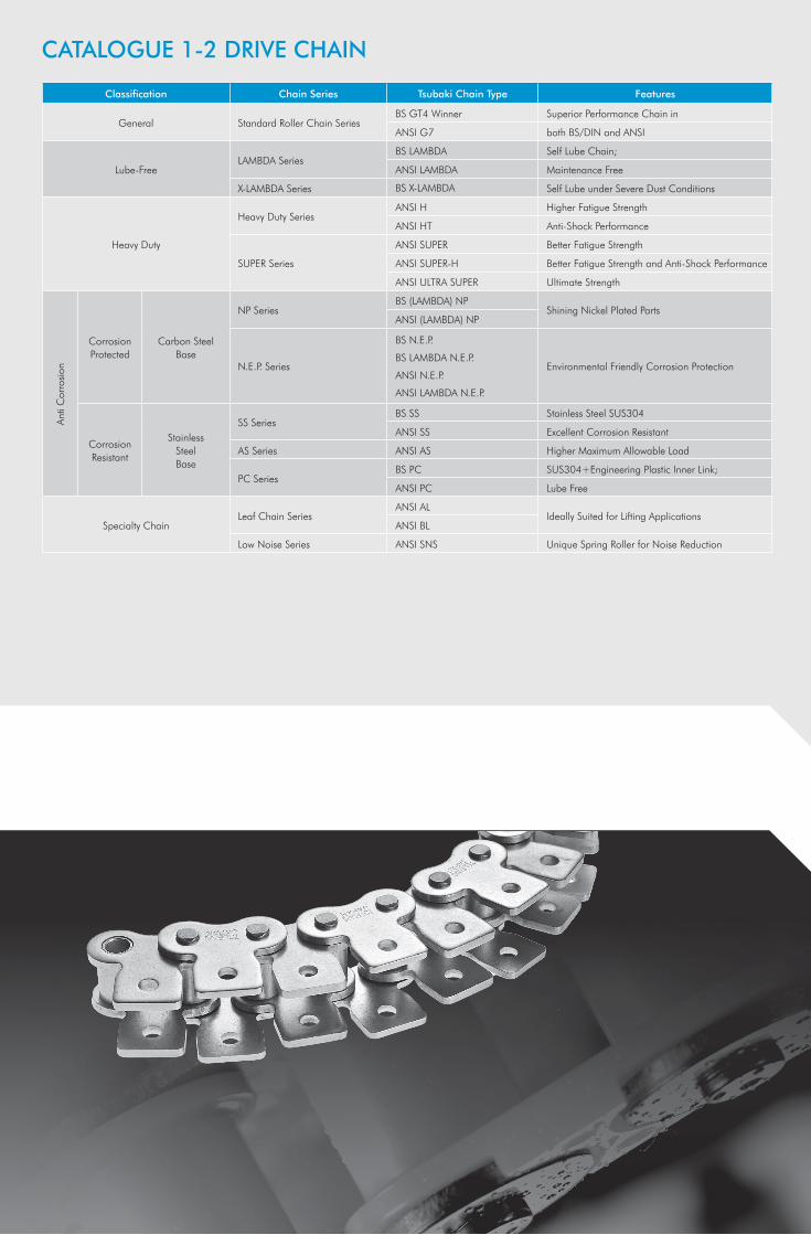
Classification Chain Series Tsubaki Chain Type Features
General Standard Roller Chain SeriesBS GT4 Winner Superior Performance Chain in
ANSI G7 both BS/DIN and ANSI
Lube-FreeLAMBDA Series
BS LAMBDA Self Lube Chain;
ANSI LAMBDA Maintenance Free
X-LAMBDA Series BS X-LAMBDA Self Lube under Severe Dust Conditions
Heavy Duty
Heavy Duty SeriesANSI H Higher Fatigue Strength
ANSI HT Anti-Shock Performance
SUPER Series
ANSI SUPER Better Fatigue Strength
ANSI SUPER-H Better Fatigue Strength and Anti-Shock Performance
ANSI ULTRA SUPER Ultimate Strength
Anti
Cor
rosi
on
Corrosion Protected
Carbon Steel Base
NP SeriesBS (LAMBDA) NP
Shining Nickel Plated PartsANSI (LAMBDA) NP
N.E.P. Series
BS N.E.P.
BS LAMBDA N.E.P.
ANSI N.E.P.
ANSI LAMBDA N.E.P.
Environmental Friendly Corrosion Protection
Corrosion Resistant
StainlessSteelBase
SS SeriesBS SS Stainless Steel SUS304
ANSI SS Excellent Corrosion Resistant
AS Series ANSI AS Higher Maximum Allowable Load
PC SeriesBS PC SUS304+Engineering Plastic Inner Link;
ANSI PC Lube Free
Specialty ChainLeaf Chain Series
ANSI ALIdeally Suited for Lifting Applications
ANSI BL
Low Noise Series ANSI SNS Unique Spring Roller for Noise Reduction

CATALOGUE 1-2 DRIVE CHAINC
ATA
LOG
UE
3 C
UST
OM
MA
DE
CH
AIN
CAT
ALO
GU
E 1-
2 A
TTA
CH
MEN
T C
HA
INClassification Chain Series Tsubaki Chain Type Features
General
BS Standard Attachment Chain Series
BS Single Pitch Standard All Major Chain Attachments Available
BS Single Pitch RF Straight Side Plate for Direct Conveying
ANSI Standard Attachment Chain Series
ANSI Single Pitch Standard All Major Chain Attachments Available
ANSI Single Pitch HP Hollow Pin Chain
ANSI Single Pitch CU Curved Chain (Side Bow Chain)
ANSI Double Pitch Standard For Longer Conveyor Lines
ANSI Double Pitch HP Hollow Pin Chain
Lube-Free
BS LAMBDA AttachmentChain Series
BS Single Pitch LAMBDA Self Lube, Maintenance Free
BS Single Pitch LAMBDA RF Self Lube, Maintenance Free
ANSI LAMBDA AttachmentChain Series
ANSI Single Pitch LAMBDA Self Lube, Maintenance Free
ANSI Single Pitch LAMBDA HP Self Lube, Hollow Pin Chain
ANSI Double Pitch LAMBDA Self Lube, Maintenance Free
Anti
Cor
rosi
on
Corrosion Protected
Carbon Steel Base
N.E.P. Attachment Chain Series
BS Single Pitch N.E.P. Environmental Friendly Corrosion Protection
Corrosion Resistant
StainlessSteel Base
SS Attachment Chain Series
BS Single Pitch SS Stainless Steel SUS304
ANSI Single Pitch SS Stainless Steel SUS304
ANSI Single Pitch SS HP SUS304, Hollow Pin
ANSI Double Pitch SS SUS304, Double Pitch
ANSI Double Pitch SS HP SUS304, Double Pitch, Hollow Pin
PC Attachment Chain Series
BS Single Pitch PC SUS304+Engineering Plastic Inner Link
ANSI Single Pitch PC SUS304+Engineering Plastic Inner Link
Plastic Base P Attachment Chain Series ANSI Single Pitch P Engineering Plastic Block+SUS304 Pins
Classification Chain Series Tsubaki Chain Type Features
ANSI Drive Chain
Lube-Free Series
ANSI LAMBDA Heavy Duty Self Lube, Increased Tensile Strength
ANSI X-LAMBDA Self Lube under Severe Dust Conditions
ANSI LAMBDA DKFHigh Temperature up to 230°C
Food Grade
Corrosion Resistant Series
ANSI TI All Titanium
ANSI PC-SY Superior Chemical Resistance
ANSI NS Ultimate Corrosion Protection, Heat Application
Cold Resistant Series ANSI KT Low Temperature Freezing Application down to -60°C
ANSI Attachment Chain
Standard SeriesANSI Single Pitch Standard
Flexible Design CapabilityANSI Double Pitch Standard
Lube-FreeSeries
Standard
ANSI Single Pitch LAMBDA Self Lube Chain
ANSI Single Pitch LAMBDA CU Curved Chain
ANSI Double Pitch LAMBDA Self Lube Chain
SpecialEnvironments
ANSI Single Pitch LAMBDA CKFHigh Temperature up to 230°C
Food Grade
ANSI Double Pitch LAMBDA CKFHigh Temperature up to 230°C
Food Grade
Corrosion Resistant Series
ANSI Single Pitch SS SUS304, Excellent Corrosion Resistant
ANSI Single Pitch SS CU SUS304, Curved Chain
ANSI Double Pitch SS SUS304, Excellent Corrosion Resistant
Conveyor Chain
Tsubaki Standard
Standard Series RF Wide Variation
Low Maintenance SeriesRF LAMBDA Self Lube, Direct Conveying
BR Bearing Roller Low Friction of Roller, Save Energy
Deep Link Series RFD Ideal for Direct Conveying
Free Flow Series VR Double Plus Chain Speed can be Reduced 2,5 Times, Save Energy
DIN Standard
Standard SeriesM
Wide VariationFV
Hollow Pin SeriesMC
Hollow PinFVC
Deep Link SeriesMT
Ideal for Direct ConveyingFVT
Scraper SeriesTFM
Scraping AttachmentsTF

3
LEADING PRODUCTS AND EXCELLENT SERVICE
At TSUBAKI we know that customers want the best. We are also aware that each and
every one of our customers has unique requirements. Therefore, we take pride in our
ability to deliver an extensive product line-up that satisfies these high expectations.
We believe that in coming years there will be an increase in demand for quality in
products as well as in services. With an eye on these future trends, we are committed
to take on the challenge of technical innovation.
Our main products, along with automotive timing-drive systems, are industrial drive chains, attachment chains and large size conveyor chains. Related products such as cam clutches, sproc-kets, shaft couplings, safety devices, toothed belts & pulleys compliment the program. In the new and modern workshop in Dordrecht, standard attachment chains can be assembled as ready-to-use items, thus saving customers time and achieving highest quality. In case of special needs it is possible to manu-facture chains completely to order.
For optimum performance and reliability, a chain has to be selected carefully. In respect of this customers can rely on our specialised sales people and our experienced field engineers for technical advice (including maintenance and chain inspection on site). To ensure a close customer contact and excellent service an exten-sive network of distribution points is strategically placed through-out Europe and other designated markets.
Tsubakimoto Europe B.V. serves the Pan-European market, Africa and the Middle East. Our headquarters are located in Dordrecht, the Netherlands, serving Power Transmission customers. From the subsidiary office in Nottingham, Tsubaki UK serves the United Kingdom, Ireland and Iceland and from the office in Gilching, Germany customers in Germany, Austria and Switzerland are served. The TSUBAKI Group includes 46 production locations and 63 group companies worldwide. Our production and sales networks are now more developed than ever.

4
Introduction to TSUBAKI Roller Chain. . . . . . . . . . . . . . . . . . . . . . . . . . . . . . . . . . . . . . . . . . . . . . . 8
- Glossary . . . . . . . . . . . . . . . . . . . . . . . . . . . . . . . . . . . . . . . . . . . . . . . . . . . . . . . . . . . . . . . . . . . . . . . 8
- Roller Chain Structure . . . . . . . . . . . . . . . . . . . . . . . . . . . . . . . . . . . . . . . . . . . . . . . . . . . . . . . . . . . . . . 10
BS LAMBDA Lube Free Roller Chain. . . . . . . . . . . . . . . . . . . . . . . . . . . . . . . . . . . . . . . . . . . . . . . . 12
- BS LAMBDA Lube Free Roller Chain - Drawings and Dimensions . . . . . . . . . . . . . . . . . . . . . . . . . . . . . . 13
BS X-LAMBDA Lube Free Roller Chain . . . . . . . . . . . . . . . . . . . . . . . . . . . . . . . . . . . . . . . . . . . . . 14
- BS X-LAMBDA Lube Free Roller Chain - Drawings and Dimensions . . . . . . . . . . . . . . . . . . . . . . . . . . . . . 15
RS Roller Chain GT4 Winner . . . . . . . . . . . . . . . . . . . . . . . . . . . . . . . . . . . . . . . . . . . . . . . . . . . . . . . 16
- BS GT4 Winner - Drawings and Dimensions . . . . . . . . . . . . . . . . . . . . . . . . . . . . . . . . . . . . . . . . . . . . . 17
BS Chain for Corrosive Environments . . . . . . . . . . . . . . . . . . . . . . . . . . . . . . . . . . . . . . . . . . . . . . 18
- BS PC Chain - Drawings and Dimensions . . . . . . . . . . . . . . . . . . . . . . . . . . . . . . . . . . . . . . . . . . . . . . . 19
- BS SS Chain - Drawings and Dimensions . . . . . . . . . . . . . . . . . . . . . . . . . . . . . . . . . . . . . . . . . . . . . . . 20
- BS LAMBDA N.E.P. Chain - Drawings and Dimensions . . . . . . . . . . . . . . . . . . . . . . . . . . . . . . . . . . . . . . 21
- BS N.E.P. Chain - Drawings and Dimensions . . . . . . . . . . . . . . . . . . . . . . . . . . . . . . . . . . . . . . . . . . . . . 22
- BS NP Chain - Drawings and Dimensions. . . . . . . . . . . . . . . . . . . . . . . . . . . . . . . . . . . . . . . . . . . . . . . 23
ANSI LAMBDA Lube Free Roller Chain . . . . . . . . . . . . . . . . . . . . . . . . . . . . . . . . . . . . . . . . . . . . . 24
- ANSI LAMBDA Lube Free Roller Chain - Drawings and Dimensions. . . . . . . . . . . . . . . . . . . . . . . . . . . . . 25
ANSI G7 Standard Roller Chain . . . . . . . . . . . . . . . . . . . . . . . . . . . . . . . . . . . . . . . . . . . . . . . . . . . 26
- ANSI G7 Standard Roller Chain - Drawings and Dimensions . . . . . . . . . . . . . . . . . . . . . . . . . . . . . . . . . 27
ANSI Chain for Corrosive Environments . . . . . . . . . . . . . . . . . . . . . . . . . . . . . . . . . . . . . . . . . . . 28
- ANSI PC Chain - Drawings and Dimensions . . . . . . . . . . . . . . . . . . . . . . . . . . . . . . . . . . . . . . . . . . . . . 29
- ANSI SS Chain - Drawings and Dimensions . . . . . . . . . . . . . . . . . . . . . . . . . . . . . . . . . . . . . . . . . . . . . 30
- ANSI AS Chain - Drawings and Dimensions . . . . . . . . . . . . . . . . . . . . . . . . . . . . . . . . . . . . . . . . . . . . . 31
TABLE OF CONTENTS

5
- ANSI LAMBDA N.E.P. Chain - Drawings and Dimensions . . . . . . . . . . . . . . . . . . . . . . . . . . . . . . . . . . . . 32
- ANSI N.E.P. Chain - Drawings and Dimensions . . . . . . . . . . . . . . . . . . . . . . . . . . . . . . . . . . . . . . . . . . . 33
- ANSI NP Chain - Drawings and Dimensions . . . . . . . . . . . . . . . . . . . . . . . . . . . . . . . . . . . . . . . . . . . . . 34
ANSI Heavy Duty Roller Chain . . . . . . . . . . . . . . . . . . . . . . . . . . . . . . . . . . . . . . . . . . . . . . . . . . . . . 35
- H Series - Drawings and Dimensions . . . . . . . . . . . . . . . . . . . . . . . . . . . . . . . . . . . . . . . . . . . . . . . . . . 36
- HT Series - Drawings and Dimensions . . . . . . . . . . . . . . . . . . . . . . . . . . . . . . . . . . . . . . . . . . . . . . . . . 37
- SUPER Series - Drawings and Dimensions. . . . . . . . . . . . . . . . . . . . . . . . . . . . . . . . . . . . . . . . . . . . . . . 38
- SUPER-H Series - Drawings and Dimensions . . . . . . . . . . . . . . . . . . . . . . . . . . . . . . . . . . . . . . . . . . . . . 39
- ULTRA SUPER Series - Drawings and Dimensions . . . . . . . . . . . . . . . . . . . . . . . . . . . . . . . . . . . . . . . . . 40
ANSI Low Noise Roller Chain . . . . . . . . . . . . . . . . . . . . . . . . . . . . . . . . . . . . . . . . . . . . . . . . . . . . . . 41
- ANSI SNS Chain - Drawings and Dimensions . . . . . . . . . . . . . . . . . . . . . . . . . . . . . . . . . . . . . . . . . . . . 42
ANSI Leaf Chain. . . . . . . . . . . . . . . . . . . . . . . . . . . . . . . . . . . . . . . . . . . . . . . . . . . . . . . . . . . . . . . . . . . 43
- AL Type - Drawings and Dimensions. . . . . . . . . . . . . . . . . . . . . . . . . . . . . . . . . . . . . . . . . . . . . . . . . . . 44
- BL Type - Drawings and Dimensions . . . . . . . . . . . . . . . . . . . . . . . . . . . . . . . . . . . . . . . . . . . . . . . . . . . 45
TSUBAKI Drive Chain Application Check Sheet. . . . . . . . . . . . . . . . . . . . . . . . . . . . . . . . . . . . . 46
TABLE OF CONTENTS
Note:
Chains which are included in this catalogue are available from stock, with the exception of the chains of which the Tsubaki chain number is indicated
with gray characters.
6
Introduction to TSUBAKI Attachment Chain . . . . . . . . . . . . . . . . . . . . . . . . . . . . . . . . . . . . . . . . . . . . . . 47
- Attachment Chain Structure . . . . . . . . . . . . . . . . . . . . . . . . . . . . . . . . . . . . . . . . . . . . . . . . . . . . . . . . . . . . 47
- Chain Types. . . . . . . . . . . . . . . . . . . . . . . . . . . . . . . . . . . . . . . . . . . . . . . . . . . . . . . . . . . . . . . . . . . . . . . . . . 51
- Attachments . . . . . . . . . . . . . . . . . . . . . . . . . . . . . . . . . . . . . . . . . . . . . . . . . . . . . . . . . . . . . . . . . . . . . . . . . 51
- Chain Length Tolerance . . . . . . . . . . . . . . . . . . . . . . . . . . . . . . . . . . . . . . . . . . . . . . . . . . . . . . . . . . . . . . . 53
- Match & Tag Service: High Accuracy, Narrow Tolerance Service . . . . . . . . . . . . . . . . . . . . . . . . . . . . . 53
- Local Assembly Service . . . . . . . . . . . . . . . . . . . . . . . . . . . . . . . . . . . . . . . . . . . . . . . . . . . . . . . . . . . . . . . . 54
BS LAMBDA Lube Free Attachment Chain . . . . . . . . . . . . . . . . . . . . . . . . . . . . . . . . . . . . . . . . . . . . . . . 55
- BS Single Pitch LAMBDA Chain - Drawings and Dimensions . . . . . . . . . . . . . . . . . . . . . . . . . . . . . . . . . . . . 56
- BS Single Pitch LAMBDA RF Chain - Drawings and Dimensions. . . . . . . . . . . . . . . . . . . . . . . . . . . . . . . . . . 57
BS Standard Attachment Chain . . . . . . . . . . . . . . . . . . . . . . . . . . . . . . . . . . . . . . . . . . . . . . . . . . . . . . . . 58
- BS Single Pitch Standard Chain - Drawings and Dimensions . . . . . . . . . . . . . . . . . . . . . . . . . . . . . . . . . . . . 59
- BS Single Pitch RF Chain - Drawings and Dimensions. . . . . . . . . . . . . . . . . . . . . . . . . . . . . . . . . . . . . . . . . 60
BS Attachment Chain for Corrosive Environments . . . . . . . . . . . . . . . . . . . . . . . . . . . . . . . . . . . . . . . . 61
- BS Single Pitch PC Chain - Drawings and Dimensions . . . . . . . . . . . . . . . . . . . . . . . . . . . . . . . . . . . . . . . . 62
- BS Single Pitch SS Chain - Drawings and Dimensions. . . . . . . . . . . . . . . . . . . . . . . . . . . . . . . . . . . . . . . . . 63
- BS Single Pitch N.E.P. Chain - Drawings and Dimensions . . . . . . . . . . . . . . . . . . . . . . . . . . . . . . . . . . . . . . 64
ANSI LAMBDA Lube Free Attachment Chain . . . . . . . . . . . . . . . . . . . . . . . . . . . . . . . . . . . . . . . . . . . . . 65
- ANSI Single Pitch LAMBDA Chain - Drawings and Dimensions . . . . . . . . . . . . . . . . . . . . . . . . . . . . . . . . . . 66
- ANSI Single Pitch LAMBDA Hollow Pin (HP) Chain - Drawings and Dimensions . . . . . . . . . . . . . . . . . . . . . . 67
- ANSI Double Pitch LAMBDA Chain - Drawings and Dimensions . . . . . . . . . . . . . . . . . . . . . . . . . . . . . . . . . 68
ANSI Standard Attachment Chain. . . . . . . . . . . . . . . . . . . . . . . . . . . . . . . . . . . . . . . . . . . . . . . . . . . . . . . .69
- ANSI Single Pitch Standard Chain - Drawings and Dimensions . . . . . . . . . . . . . . . . . . . . . . . . . . . . . . . . . . 70
- ANSI Single Pitch Hollow Pin (HP) Chain - Drawings and Dimensions . . . . . . . . . . . . . . . . . . . . . . . . . . . . . 71
TABLE OF CONTENTS

7
- ANSI Single Pitch Curved (CU) Chain - Drawings and Dimensions . . . . . . . . . . . . . . . . . . . . . . . . . . . . . . . 72
- ANSI Double Pitch Standard Chain - Drawings and Dimensions . . . . . . . . . . . . . . . . . . . . . . . . . . . . . . . . . 73
- ANSI Double Pitch Hollow Pin (HP) Chain - Drawings and Dimensions . . . . . . . . . . . . . . . . . . . . . . . . . . . . 74
ANSI Attachment Chain for Corrosive Environments . . . . . . . . . . . . . . . . . . . . . . . . . . . . . . . . . . . . . . 75
- ANSI Single Pitch P Chain - Drawings and Dimensions. . . . . . . . . . . . . . . . . . . . . . . . . . . . . . . . . . . . . . . . 76
- ANSI Single Pitch PC Chain - Drawings and Dimensions . . . . . . . . . . . . . . . . . . . . . . . . . . . . . . . . . . . . . . 77
- ANSI Single Pitch SS Chain - Drawings and Dimensions . . . . . . . . . . . . . . . . . . . . . . . . . . . . . . . . . . . . . . . 78
- ANSI Single Pitch SS Hollow Pin (HP) Chain - Drawings and Dimensions . . . . . . . . . . . . . . . . . . . . . . . . . . . 79
- ANSI Double Pitch SS Chain - Drawings and Dimensions . . . . . . . . . . . . . . . . . . . . . . . . . . . . . . . . . . . . . . 80
- ANSI Double Pitch SS Hollow Pin (HP) Chain - Drawings and Dimensions . . . . . . . . . . . . . . . . . . . . . . . . . . 81
Stock Specialty Attachment Chain . . . . . . . . . . . . . . . . . . . . . . . . . . . . . . . . . . . . . . . . . . . . . . . . . . . . . . 82
TSUBAKI Attachment Chain Application Check Sheet. . . . . . . . . . . . . . . . . . . . . . . . . . . . . . . . . . . . . . 83
TSUBAKI Attachment Chain Layout Sheet. . . . . . . . . . . . . . . . . . . . . . . . . . . . . . . . . . . . . . . . . . . . . . . . 84
Temperature Selection Method . . . . . . . . . . . . . . . . . . . . . . . . . . . . . . . . . . . . . . . . . . . . . . . . . . . . . . . . 85
Corrosion Resistance Guide . . . . . . . . . . . . . . . . . . . . . . . . . . . . . . . . . . . . . . . . . . . . . . . . . . . . . . . . . . . 86
General Terms and Conditions of Sale Tsubakimoto Europe B.V. . . . . . . . . . . . . . . . . . . . . . . . . . . . . 88
For Safe Use . . . . . . . . . . . . . . . . . . . . . . . . . . . . . . . . . . . . . . . . . . . . . . . . . . . . . . . . . . . . . . . . . . . . . . . . 89
TABLE OF CONTENTS
Note:
Chains which are included in this catalogue are available from stock, with the exception of the chains of which the Tsubaki chain number is indicated
with gray characters.
8
Tensile Strength
ISO min. Tensile Strength
TSUBAKI min. Tensile Strength
TSUBAKI av. Tensile Strength
Freq
uenc
y
Load
Pmin
Pm
Pa
Pmax
Time
INTRODUCTION TO TSUBAKI ROLLER CHAIN
Glossary
1. Minimum Tensile Strength as per ISO Standar disation
This is the Minimum Tensile Strength determined by ISO. If a roller chain fails a tensile load below this value, it does not surpass the standards.
2. Minimum Tensile Strength as per TSUBAKI Standardisation
This is a minimum value determined by statistical processes at TSUBAKI. If a roller chain fractures at a tensile load below this value, it does not surpass TSUBAKI standards. TSUBAKI standards are higher than ISO standards.
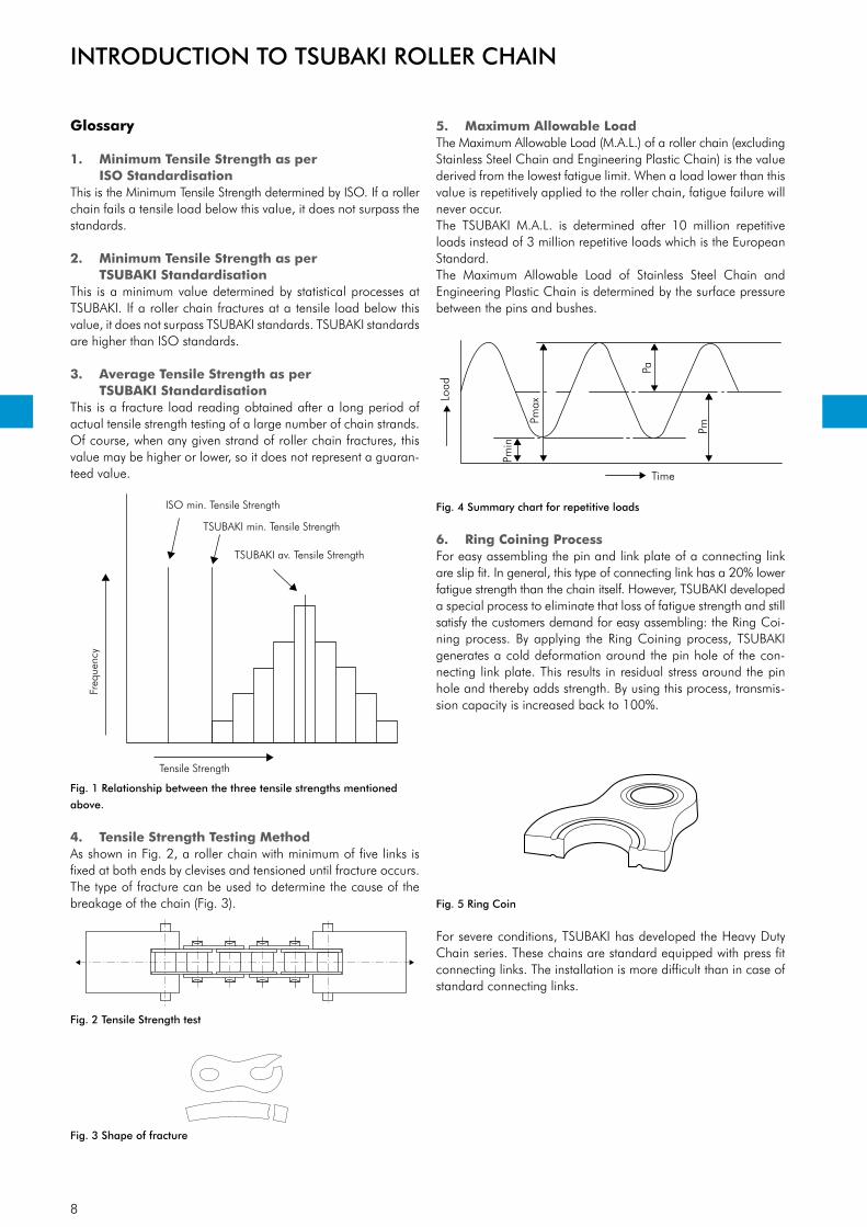
3. Average Tensile Strength as per TSUBAKI Standardisation
This is a fracture load reading obtained after a long period of actual tensile strength testing of a large number of chain strands. Of course, when any given strand of roller chain fractures, this value may be higher or lower, so it does not represent a guaran-teed value.
Fig. 1 Relationship between the three tensile strengths mentioned
above.
4. Tensile Strength Testing MethodAs shown in Fig. 2, a roller chain with minimum of five links is fixed at both ends by clevises and tensioned until fracture occurs. The type of fracture can be used to determine the cause of the breakage of the chain (Fig. 3).
5. Maximum Allowable LoadThe Maximum Allowable Load (M.A.L.) of a roller chain (excluding Stainless Steel Chain and Engineering Plastic Chain) is the value derived from the lowest fatigue limit. When a load lower than this value is repetitively applied to the roller chain, fatigue failure will never occur.The TSUBAKI M.A.L. is determined after 10 million repetitive loads instead of 3 million repetitive loads which is the European Standard.The Maximum Allowable Load of Stainless Steel Chain and Engineering Plastic Chain is determined by the surface pressure between the pins and bushes.
Fig. 4 Summary chart for repetitive loads
6. Ring Coining ProcessFor easy assembling the pin and link plate of a connecting link are slip fit. In general, this type of connecting link has a 20% lower fatigue strength than the chain itself. However, TSUBAKI developed a special process to eliminate that loss of fatigue strength and still satisfy the customers demand for easy assembling: the Ring Coi-ning process. By applying the Ring Coining process, TSUBAKI generates a cold deformation around the pin hole of the con-necting link plate. This results in residual stress around the pin hole and thereby adds strength. By using this process, transmis-sion capacity is increased back to 100%.
Fig. 5 Ring Coin
For severe conditions, TSUBAKI has developed the Heavy Duty Chain series. These chains are standard equipped with press fit connecting links. The installation is more difficult than in case of standard connecting links.
Fig. 2 Tensile Strength test
Fig. 3 Shape of fracture

9
Ball-drift
Residualcompressive stress Repetitive loadRepetitive load
7. Ball Drifting Process
Fig. 6 Ball Drifting
Fig. 7 Residual Compressive Stress
Ball drifting is the process of pressing a hardened steel ball through a hole in an already hardened steel plate (Fig. 6). The goal of this process is to create local plastic deformation and effectively add compressive stress (Fig. 7) to the walls of the hole. Besides this, the process generates precisely controlled holes for an optimum press fit. Together, this leads to significantly improved fatigue life (up to 30%).
8. Shot Peening ProcessShot peening is a process used to produce a compressive residual stress layer and modify mechanical properties of metals. It means impacting a surface with shot (round metallic or ceramic particles) with force sufficient to create plastic deformation.At TSUBAKI, all basic chain parts (except pins and bushes) are shot peened.
Fig. 8 Shot Peening
Shot Peening increases resistance to:• fatigue failure • corrosion fatigue • hydrogen assisted cracking • cavitation erosion • stress corrosion cracking • galling • fretting
9. Pre-Loading Process
Fig. 9 Pre-Loading
After the assembly of a chain, TSUBAKI applies an initial load, which is called a pre-load. The pre-load force approximates the recommended Maximum Allowable Load and is applied to seat the various chain components such as pins, bushes and link plates. The benefit of pre-loading is that it minimizes the initial elongation. Minimization of this initial elongation increases the chains service life therefore pre-loading is very important.
10. Super Long LengthAs chain size increases, so does the burden of connecting it for the user. TSUBAKI can connect the chain at the desired length prior to delivery increasing our customer’s work productivity and helps maintain a safe working environment.
11. Match & TagThe “Matchy” is an in-house facility which allows TSUBAKI Eu-rope to supply customers with drive or attachment chain in pairs or multiples that require a specific overall chain length tolerance.
INTRODUCTION TO TSUBAKI ROLLER CHAIN
10
Roller
DiameterPre
ss Fit
Pitch
Press F
it
Pin Link
Pin
Roller Link
Press F
it
Bush
Roller
Inner width
Roller Link Plate
Pin Link Plate
Connecting Lin
k Plate
Roller Chain
Connecting Lin
kSpring Clip
Offset Li
nkCotter Pi
n
Slip Fit
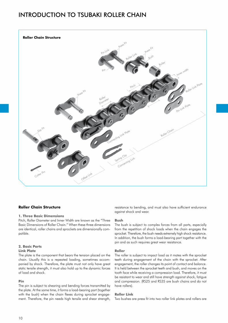
Roller Chain Structure
1. Three Basic DimensionsPitch, Roller Diameter and Inner Width are known as the “Three Basic Dimensions of Roller Chain.” When these three dimensions are identical, roller chains and sprockets are dimensionally com-patible.
2. Basic PartsLink PlateThe plate is the component that bears the tension placed on the chain. Usually this is a repeated loading, sometimes accom-panied by shock. Therefore, the plate must not only have great static tensile strength, it must also hold up to the dynamic forces of load and shock.
PinThe pin is subject to shearing and bending forces transmitted by the plate. At the same time, it forms a load-bearing part (together with the bush) when the chain flexes during sprocket engage-ment. Therefore, the pin needs high tensile and shear strength,
resistance to bending, and must also have sufficient endurance against shock and wear.
BushThe bush is subject to complex forces from all parts, especially from the repetition of shock loads when the chain engages the sprocket. Therefore, the bush needs extremely high shock resistance. In addition, the bush forms a load-bearing part together with the pin and as such requires great wear resistance.
RollerThe roller is subject to impact load as it mates with the sprocket teeth during engagement of the chain with the sprocket. After engagement, the roller changes its point of contact and balance. It is held between the sprocket teeth and bush, and moves on the tooth face while receiving a compression load. Therefore, it must be resistant to wear and still have strength against shock, fatigue and compression. (RS25 and RS35 are bush chains and do not have rollers). Roller LinkTwo bushes are press fit into two roller link plates and rollers are
INTRODUCTION TO TSUBAKI ROLLER CHAIN
Roller Chain Structure

11
inserted to allow rotation around the outside of the bushes during operation. This is the same for single and for multi strand chains.
Pin Link and Intermediate PlateThe pin link consists of two pins that have been press fit into two pin link plates. In case of multi-strand roller chain up till size 08B, an intermediate plate is added to the pin link. In case of multi-strand roller chain above size 08B, two intermediate plates are added to the pin link. The intermediate plates are slip fit for standard roller chain and press fit for SUPER roller chain.
3. Assembly PartsRoller chains are usually made up of a number of inner and outer links in an endless formation. Although offset links can be used when there is an odd number of links in the roller chain, it is bet-ter to use a design that requires an even number of links. If an odd number of links cannot be avoided, it is recommended to use a two-pitch offset link in stead of a one-pitch offset link. As it is riveted into the chain, a two-pitch offset link has a 100% (ap-plicable to ANSI chain) Maximum Allowable Load, where as the one-pitch offset link has a Maximum Allowable Load of 65% (applicable to ANSI chain).
Connecting LinksThere are three types of connecting links: spring clip connecting link, cotter pin connecting link and spring pin connecting link.
It’s common to use slip fit spring clip connecting links for small size roller chains. Cotter pin and spring pin connecting links are used for large size roller chains and on customer request.
Offset LinksAn offset link is used when an odd number of chain links is required. Different types are available:
One pitch offset link (OL). The pin and two plates are slip fit. The fatigue strength is 35% (applicable to ANSI chain) lower than the chain itself.
Two pitch offset link (2POL).Two pitch offset links are the combination of a roller link and an offset link connected with a rivet pin. Please refer to the dimen-sion tables for roller chain types and sizes suitable for offset links.
Spring ClipConnecting Link
Cotter Pin Connecting Link
Cotter Pin Connecting Link Multi-Strand
(2-strand shown)Spring Pin
Connecting Link
Intermediate Plate(s)
Spring Pin Connecting Link Plate
Pin Link Plate
Pin
Spring Clip Connecting Link Plate
Cotter Pin
Pin Link PlatePin Link Plate
Connecting Link Plate
Cotter Pin
INTRODUCTION TO TSUBAKI ROLLER CHAIN
ONE Pitch Offset Links (OL) TWO Pitch Offset Links (2POL)
Single StrandMulti-strand(2-strand shown)
Multi-strand(2-strand shown)
Offset Link PlateCotter Pin
Pin
Rivet Pin
Single Strand
Offset Link Plate
Pin
Connecting Links
12
Technical EvolutionAs a pioneer in the lube-free chain market, TSUBAKI will reveal some of the key elements behind BS LAMBDA’s outstanding per-formance:
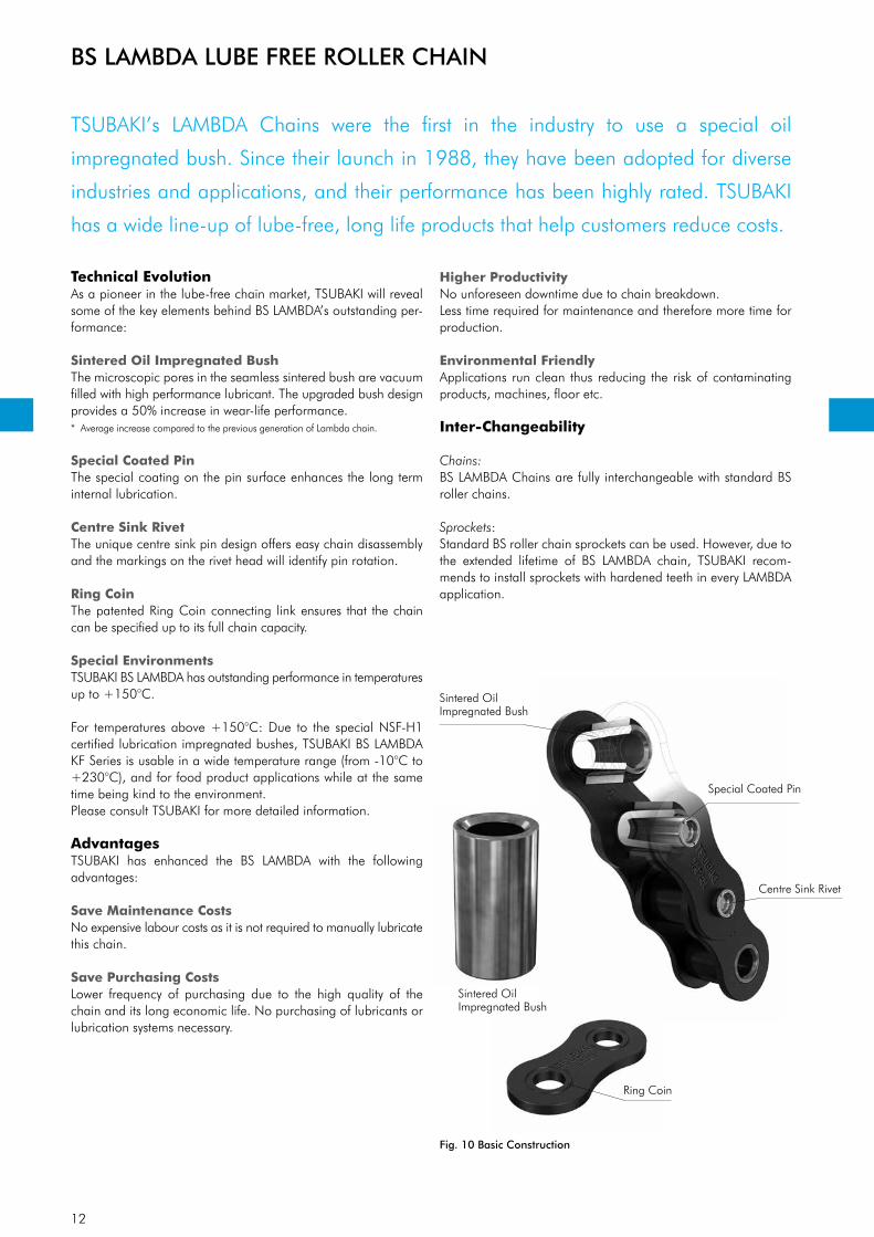
Sintered Oil Impregnated BushThe microscopic pores in the seamless sintered bush are vacuum filled with high performance lubricant. The upgraded bush design provides a 50% increase in wear-life performance. * Average increase compared to the previous generation of Lambda chain.
Special Coated PinThe special coating on the pin surface enhances the long term internal lubrication.
Centre Sink RivetThe unique centre sink pin design offers easy chain disassembly and the markings on the rivet head will identify pin rotation.
Ring CoinThe patented Ring Coin connecting link ensures that the chain can be specified up to its full chain capacity.
Special EnvironmentsTSUBAKI BS LAMBDA has outstanding performance in temperatures up to +150°C.
For temperatures above +150°C: Due to the special NSF-H1 certified lubrication impregnated bushes, TSUBAKI BS LAMBDA KF Series is usable in a wide temperature range (from -10°C to +230°C), and for food product applications while at the same time being kind to the environment.Please consult TSUBAKI for more detailed information.
AdvantagesTSUBAKI has enhanced the BS LAMBDA with the following advantages:
Save Maintenance CostsNo expensive labour costs as it is not required to manually lubricate this chain.
Save Purchasing CostsLower frequency of purchasing due to the high quality of the chain and its long economic life. No purchasing of lubricants or lubrication systems necessary.
Higher ProductivityNo unforeseen downtime due to chain breakdown.Less time required for maintenance and therefore more time for production.
Environmental FriendlyApplications run clean thus reducing the risk of contaminating products, machines, floor etc.
Inter-Changeability
Chains:BS LAMBDA Chains are fully interchangeable with standard BS roller chains.
Sprockets:Standard BS roller chain sprockets can be used. However, due to the extended lifetime of BS LAMBDA chain, TSUBAKI recom-mends to install sprockets with hardened teeth in every LAMBDA application.
BS LAMBDA LUBE FREE ROLLER CHAIN
TSUBAKI’s LAMBDA Chains were the first in the industry to use a special oil
impregnated bush. Since their launch in 1988, they have been adopted for diverse
industries and applications, and their performance has been highly rated. TSUBAKI
has a wide line-up of lube-free, long life products that help customers reduce costs.
Fig. 10 Basic Construction
Sintered Oil Impregnated Bush
Special Coated Pin
Centre Sink Rivet
Ring Coin
Sintered Oil Impregnated Bush

13
L2
L1
d2 d1
p
H
T
t
p
b1
d2 d1
T
b1
L2
L1 t
pt
OL
L
L1
L1
2POL
BS LAMBDA LUBE FREE ROLLER CHAIN
TSUBAKIChain No.
PitchRoller
DiameterInnerWidth
Pin Link Plate
TransversePitch
Min. Tensile Strengthacc. to
ISO 606Approx.MassDiameter Length Length Length Thickness Thickness Height
p d1 b1 d2 L1 L2 L T t H (max) pt kN kg/m
RF06B-LM-1 9.525 (3/8”) 6.35 5.72 3.28
6.10 7.70 15.101.30 1.00 8.20
- 8.9 0.39RF06B-LM-2 11.20 12.80 25.90 10.24 16.9 0.75RS08B-LM-1
12.70 (1/2”) 8.51 7.75 4.45 8.40 10.00 18.60
1.60 1.60 11.80- 17.8 0.70
RS08B-LM-2 15.30 16.90 34.50 13.92 31.1 1.35RS10B-LM-1
15.875 (5/8”) 10.16 9.65 5.08 9.55 11.25 20.80
1.50 1.50 14.70- 22.2 0.95
RS10B-LM-2 17.85 19.55 39.40 16.59 44.5 1.85RS12B-LM-1
19.05 (3/4”) 12.07 11.68 5.7211.10 13.00 24.40
1.80 1.80 16.10- 28.9 1.25
RS12B-LM-2 20.85 22.75 45.90 19.46 57.8 2.50RS16B-LM-1
25.40 (1”) 15.88 17.02 8.2817.75 19.95 41.10
4.00 3.20 21.00- 60.0 2.70
RS16B-LM-2 33.55 35.75 75.20 31.88 106.0 5.40RS20B-LM-1
31.75 (1 1/4”) 19.05 19.56 10.1919.90 23.10 46.60
4.40 3.40 26.40- 95.0 3.85
RS20B-LM-2 38.25 41.45 84.60 36.45 170.0 7.65RS24B-LM-1
38.10 (1 1/2”) 25.40 25.40 14.6326.65 31.85 61.70
6.00 5.60 33.40- 160.0 7.45
RS24B-LM-2 50.80 56.00 112.80 48.36 280.0 14.65
Dimensions in mm
Note:
1. Connecting links are clip type for sizes up to RS16B-LM, and cotter type for sizes RS20B-LM to RS24B-LM.
2. RF06B-LM chain has flat shaped link plates.
3. Intermediate plate of RF06B-LM-2 and RS08B-LM-2 is a solid plate.
4. Centre sink riveting is applied for RS08B-LM-1 to RS16B-LM-1. Double stake riveting is applied to all other sizes including multi-strand chain.
5. Warning: previous generations of Lambda chain can not be connected with the above chains due to different dimensions.
6. When a single pitch offset link is used, please calculate a 40% reduction of the fatigue strength.
7. Also available in N.E.P. specification.
8. The improved bush design is applicable on RF06B until RS16B.
BS LAMBDA Chain

14
Special Coated PinSpecial Oil ImpregnatedSintered Bush
Roller
Felt Seal
Felt Seal
Connecting Link
Felt SealFelt Seal
Spring Clip
Connecting Link Plate
Ten years after introducing the number-one LAMBDA Chain to the market in 1988,
TSUBAKI has developed innovative technology that sets the bar even higher for
lube-free chain performance. To the user the benefits that X-LAMBDA provides mean
increased productivity, reduced maintenance and a cleaner working environment.
Technical Evolution of BS LAMBDABS X-LAMBDA chain is a quantum leap for power transmission technology. The basic BS LAMBDA components (a special coated pin and an oil-impregnated sintered bush) come completed with special felt seals (patent pending) between inner and outer link plate that lock in lubrication while keeping dirt and abrasives out.
Because of this evolution BS X-LAMBDA chain greatly increases the performance of the BS LAMBDA chains. When your operation needs to run clean, when machines and conveyed materials must be free from contact with oil, or when lubrication is difficult, BS X-LAMBDA chain can extend the life of your operation drasti-cally.
Fig. 11 Basic Construction
AdvantagesAdditional to all BS LAMBDA advantages, TSUBAKI has enhanced the BS X-LAMBDA with the following additional advantages:
Extended Wear LifeEven longer wear life than BS LAMBDA chain (over 5 times longer).
Applicable in Dusty EnvironmentsExtra protection of critical areas due to the specially developed felt seal.
Connecting MethodWhen connecting the chain, use a BS X-LAMBDA chain con-necting link (with a felt seal). As shown in Fig. 12 insert felt seals between the outer plate and the connecting link plate, then attach the link.
Fig. 12 Connecting Method BS X-LAMBDA
Inter-Changeability
Chains:BS X-LAMBDA chain is interchangeable with standard BS roller chain. However, as the pins are longer than those of the standard BS roller chain, please make sure that there is no interference with the machine.
Sprockets:Standard BS roller chain sprockets can be used. However, due to the extended lifetime of BS X-LAMBDA chain, TSUBAKI advises to install sprockets with hardened teeth in every LAMBDA appli-cation.
BS X-LAMBDA LUBE FREE ROLLER CHAIN

15
BS X-LAMBDA LUBE FREE ROLLER CHAIN
TSUBAKIChain No.
PitchRoller
DiameterInnerWidth
Pin Link Plate
Min. Tensile Strengthacc. to
ISO 606Approx. MassDiameter Length Length Thickness Thickness Height
p d1 b1 d2 L1 L2 T t H (max) kN kg/m
RS08B-LMX-1 12.70 (1/2”) 8.51 7.75 4.45 9.00 10.60 1.60 1.60 11.80 17.8 0.70RS10B-LMX-1 15.875 (5/8”) 10.16 9.65 5.08 10.30 12.00 1.50 1.50 14.70 22.2 0.95RS12B-LMX-1 19.05 (3/4”) 12.07 11.68 5.72 11.90 13.80 1.80 1.80 16.10 28.9 1.25RS16B-LMX-1 25.40 (1”) 15.88 17.02 8.28 18.55 21.75 4.00 3.20 21.00 60.0 2.70
Dimensions in mm
Note:
1. Connecting links are clip type for sizes up to RS12B-LMX, and cotter type for size RS16B-LMX.
2. Due to the use of the felt seal, the pins are longer. Check for machine interference.
3. X-LAMBDA offset links are not available.
4. X-LAMBDA double strand chain is not available.
5. Due to the oil in the felt seal, more oil adheres to the surface of X-LAMBDA chain than regular LAMBDA chain.
BS X-LAMBDA Chain
L2L1
d2 d1
p
HT
t
p
b1

16
TSUBAKI GT4 Winner is the most advanced BS/DIN standard roller chain in the
European market. Since 1917 Tsubakimoto Chain Company has maintained a line-up
of cutting-edge chain products with exceptional quality and performance. TSUBAKI is
proud of the 4th generation, enhanced European premium BS/DIN chain.
AdvantagesTSUBAKI RS roller chain GT4 Winner is enhanced with the following advantages:
Wear resistanceTSUBAKI’s patented LG (Lube Groove) seamless bushes are precision components and perfectly cylindrical. Our special lube grooves hold oil at the point of contact, where the chain needs it most. The result is a chain that lasts longer with lower maintenance costs over the lifetime of the chain. The Lube Groove is applied to RS16B, RS20B and RS24B.
Easy disassembling with centre sink pin designThe chains can be easily and safely disassembled with a standard screw type cutter without damaging bushes. Center sink riveting is applied to RS08B up to RS16B single strand chain.
Increased kW RatingThe TSUBAKI Ring Coining process on the connecting link plate allows the chain to be specified up to its full kW rating.
In general, connecting links have a 20% lower fatigue strength than the chain itself. However, TSUBAKI developed a special process to eliminate that loss of fatigue strength and still satisfy the customers demand for easy assembly: the Ring Coining process. Genera-ting a cold deformation around the pin hole of the connecting link plate results in residual stress around this region, thereby adding strength. By using this process we can achieve 100% transmission capacity of the base chain.
Constant Quality LevelIn pursuit of outstanding quality, every TSUBAKI chain is made of a special steel alloy, the specification of which has been developed by the TSUBAKI engineering department for selected steel mills to work with. TSUBAKI produces the GT4 Winner under highly controlled conditions in its advanced heat treatment facilities. This, in combination with TSUBAKI fatigue strength tests, ensures that our customers can always rely on a constant level of quality whenever using TSUBAKI products.
Customized Pre-Lubrication ServiceProper lubrication is the key to extending the life and improving the performance of a chain. In order to get the best performance in general applications (-10°C to +60°C), all GT4 Winner drive chains are pre-lubricated.
For special applications, TSUBAKI can provide chains which are pre-lubricated with a special lubricant on customer demand:
• High temperature• Low temperature• Food safe• Outdoor exposure• Dusty environment
Please consult TSUBAKI for more detailed information.
RS ROLLER CHAIN GT4 WINNER
Fig. 13 Ring Coined Connecting Link Plate
17
L2
L1
d2 d1
p
H
T
t
p
b1
d2 d1
T
b1
L2
L1 t
pt
d2 d1
T
b1 L2
L1
t pt
pt
OL
L
L1
L1
2POL
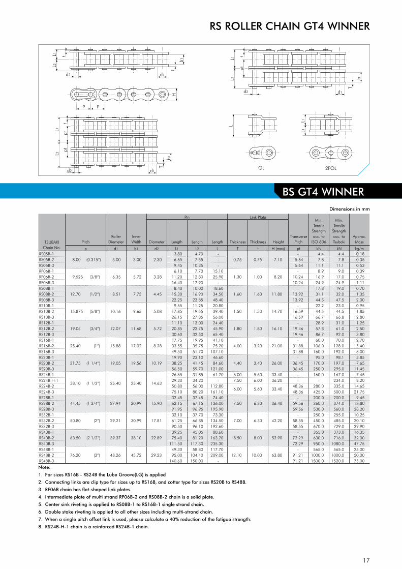
Dimensions in mm
Note:
1. For sizes RS16B - RS24B the Lube Groove(LG) is applied
2. Connecting links are clip type for sizes up to RS16B, and cotter type for sizes RS20B to RS48B.
3. RF06B chain has flat-shaped link plates.
4. Intermediate plate of multi strand RF06B-2 and RS08B-2 chain is a solid plate.
5. Center sink riveting is applied to RS08B-1 to RS16B-1 single strand chain.
6. Double stake riveting is applied to all other sizes including multi-strand chain.
7. When a single pitch offset link is used, please calculate a 40% reduction of the fatigue strength.
8. RS24B-H-1 chain is a reinforced RS24B-1 chain.
BS GT4 WINNER
RS ROLLER CHAIN GT4 WINNER
TSUBAKIChain No.
PitchRoller
DiameterInner Width
Pin Link Plate
Transverse Pitch
Min. Tensile
Strength acc. to
ISO 606
Min. Tensile
Strengthacc. to Tsubaki
Approx. MassDiameter Length Length Length Thickness Thickness Height
p d1 b1 d2 L1 L2 L T t H (max) pt kN kN kg/mRS05B-1
8.00 (0.315”) 5.00 3.00 2.303.80 4.70 -
0.75 0.75 7.10- 4.4 4.4 0.18
RS05B-2 6.65 7.55 - 5.64 7.8 7.8 0.35RS05B-3 9.45 10.35 - 5.64 11.1 11.1 0.53RF06B-1
9.525 (3/8”) 6.35 5.72 3.286.10 7.70 15.10
1.30 1.00 8.20- 8.9 9.0 0.39
RF06B-2 11.20 12.80 25.90 10.24 16.9 17.0 0.75RF06B-3 16.40 17.90 - 10.24 24.9 24.9 1.11RS08B-1
12.70 (1/2”) 8.51 7.75 4.458.40 10.00 18.60
1.60 1.60 11.80- 17.8 19.0 0.70
RS08B-2 15.30 16.90 34.50 13.92 31.1 32.0 1.35RS08B-3 22.25 23.85 48.40 13.92 44.5 47.5 2.00RS10B-1
15.875 (5/8”) 10.16 9.65 5.089.55 11.25 20.80
1.50 1.50 14.70- 22.2 23.0 0.95
RS10B-2 17.85 19.55 39.40 16.59 44.5 44.5 1.85RS10B-3 26.15 27.85 56.00 16.59 66.7 66.8 2.80RS12B-1
19.05 (3/4”) 12.07 11.68 5.7211.10 13.00 24.40
1.80 1.80 16.10- 28.9 31.0 1.25
RS12B-2 20.85 22.75 45.90 19.46 57.8 61.0 2.50RS12B-3 30.60 32.50 65.40 19.46 86.7 92.0 3.80RS16B-1
25.40 (1”) 15.88 17.02 8.2817.75 19.95 41.10
4.00 3.20 21.00- 60.0 70.0 2.70
RS16B-2 33.55 35.75 75.20 31.88 106.0 128.0 5.40RS16B-3 49.50 51.70 107.10 31.88 160.0 192.0 8.00RS20B-1
31.75 (1 1/4”) 19.05 19.56 10.1919.90 23.10 46.60
4.40 3.40 26.00- 95.0 98.1 3.85
RS20B-2 38.25 41.45 84.60 36.45 170.0 197.0 7.65RS20B-3 56.50 59.70 121.00 36.45 250.0 295.0 11.45RS24B-1
38.10 (1 1/2”) 25.40 25.40 14.63
26.65 31.85 61.70 6.00 5.60 33.40 - 160.0 167.0 7.45RS24B-H-1 29.30 34.20 - 7.50 6.00 36.20 - - 234.0 8.20RS24B-2 50.80 56.00 112.80
6.00 5.60 33.4048.36 280.0 335.0 14.65
RS24B-3 75.10 80.20 161.10 48.36 425.0 500.0 21.75RS28B-1
44.45 (1 3/4”) 27.94 30.99 15.9032.45 37.45 74.40
7.50 6.30 36.40- 200.0 200.0 9.45
RS28B-2 62.15 67.15 136.00 59.56 360.0 374.0 18.80RS28B-3 91.95 96.95 195.90 59.56 530.0 560.0 28.20RS32B-1
50.80 (2”) 29.21 30.99 17.8132.10 37.70 73.30
7.00 6.30 42.20- 250.0 255.0 10.25
RS32B-2 61.25 66.85 134.50 58.55 450.0 485.0 20.10RS32B-3 90.50 96.10 192.60 58.55 670.0 729.0 29.90RS40B-1
63.50 (2 1/2”) 39.37 38.10 22.8939.25 45.05 88.60
8.50 8.00 52.90- 355.0 373.0 16.35
RS40B-2 75.40 81.20 163.20 72.29 630.0 716.0 32.00RS40B-3 111.50 117.30 235.30 72.29 950.0 1080.0 47.75RS48B-1
76.20 (3”) 48.26 45.72 29.2349.30 58.80 117.70
12.10 10.00 63.80- 565.0 565.0 25.00
RS48B-2 95.00 104.40 209.00 91.21 1000.0 1000.0 50.00RS48B-3 140.60 150.00 - 91.21 1500.0 1520.0 75.00

18
BS CHAIN FOR CORROSIVE ENVIRONMENTS
Corrosion Resistant Chain(Stainless Steel base)
BS PC Engineering Plastic Combination ChainThe pins and pin link plates of these chains are made of SUS304 equivalent (spring clips SUS301). Engineering plastic (white) is used for the inner link. This combination makes it a lube-free, low noise (5 dB lower than BS standard roller chain) and light-weight chain (50% lighter than BS standard roller chain). Working temperature range: -20°C to +80°C. For details on cor-rosion resistance, please check out the table in the back of this catalogue.
BS SS Stainless Steel ChainAll basic components of this chain are made of SUS304 equiva-lent Stainless Steel (except the spring clips, which are made of SUS301).This chain can be used in special environments such as under-water, acidic and alkaline applications. It can also be used in high and low temperatures (-20°C to +400°C). SUS304 equiva-lent is only marginally magnetic, which is the result of the cold-forging process. For details on corrosion resistance, please check out the table in the back of this catalogue.
Corrosion Protected Chain(Carbon Steel base)
BS N.E.P. New Environmental Plating ChainBS N.E.P. Chain is a TSUBAKI BS chain that has undergone a special surface treatment. The link plates, bushes and bearing pins have a special three stage layer applied in order to provide the maximum protection from the operating or environmental conditions. (Spring clips are SUS301). N.E.P. Rollers have a special coating designed to resist the corrosive conditions as well as the severe dynamic contact between roller and sprocket.
This chain is suitable for use in environments exposed to sea-water, acid-rain and other adverse weather conditions. This chain does not contain any chemically hazardous substances such as Hexavalent Chromium, Lead, Cadmium and Mercury as regula-ted by RoHS√. The kilowatt ratings are the same as those of the corresponding BS chain with a working temperature range: -10°C to +150°C. Above +60°C a special high-temperature lubrication is required. Of course, BS LAMBDA N.E.P. chain is also available.
BS NP Nickel Plated ChainBS NP Chain is a TSUBAKI BS chain that has been plated with Nickel. NP Chain has a light corrosion resistance and an attrac-tive appearance. NP Chain is suitable for outdoor conditions exposed to water. There is a 15% reduction in Maximum Allowable Load compared to the corresponding BS chain, so please take this into account when making your chain selection. It has a working temperature range of: -10°C to +60°C. Of course, BS LAMBDA NP chain is also available.
√ RoHS = Restriction of Hazardous Substances
Whether your operation requires a sanitary environment, is exposed to corrosive
chemicals, is heated to extreme temperatures, runs through a freezer, is exposed to
the outdoors or is affected by excessive moisture: our specially designed and tested
chains will outlast your current chains and contribute to a cost effective application.
19
L2L1
d2
p
HT
t
p
b1
d1
BS CHAIN FOR CORROSIVE ENVIRONMENTS
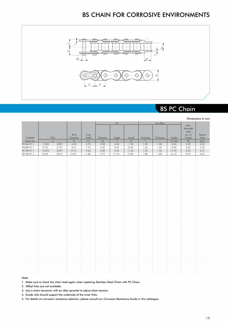
Dimensions in mm
TSUBAKIChain No.
PitchBush
DiameterInner Width
Pin Link PlateMax.
Allowable Load
acc. to Tsubaki
Approx. MassDiameter Length Length Thickness Thickness Height
p d1 b1 d2 L1 L2 T t H (max) kN kg/mRF06B-PC-1 9.525 (3/8”) 6.35 5.72 3.28 6.50 7.25 1.30 1.00 8.20 0.20 0.23RS08B-PC-1 12.70 (1/2”) 8.51 7.75 4.45 8.35 10.05 1.60 1.50 12.00 0.46 0.40RS10B-PC-1 15.875 (5/8”) 10.16 9.65 5.08 9.55 11.25 1.50 1.50 14.70 0.53 0.51RS12B-PC-1 19.05 (3/4”) 12.07 11.68 5.72 11.10 13.00 1.80 1.80 16.10 0.70 0.67
Note:
1. Make sure to check the chain load again when replacing Stainless Steel Chain with PC Chain.
2. Offset links are not available.
3. Use a chain tensioner with an idler sprocket to adjust chain tension.
4. Guide rails should support the underside of the inner links.
5. For details on corrosion resistance selection, please consult our Corrosion Resistance Guide in this catalogue.
BS PC ChainBS PC Chain

20
L2
L1
d2 d1
p
H
T
t
p
b1
d2 d1
T
b1
L2
L1 t
pt
d2 d1
T
b1 L2
L1
t pt
pt
OL
L
L1
L1
2POL
BS CHAIN FOR CORROSIVE ENVIRONMENTS
BS SS ChainDimensions in mm
TSUBAKIChain No.
PitchRoller
DiameterInner Width
Pin Link Plate
Transverse Pitch
Max. Allowable
Loadacc. to Tsubaki
Approx. MassDiameter Length Length Length Thickness Thickness Height
p d1 b1 d2 L1 L2 L T t H (max) pt kN kg/mRF06B-SS-1
9.525 (3/8”) 6.35 5.72 3.286.50 7.25 15.45
1.30 1.00 8.20- 0.27 0.39
RF06B-SS-2 11.60 12.30 25.85 10.24 0.53 0.75RS08B-SS-1
12.70 (1/2”) 8.51 7.75 4.458.35 10.05 20.05
1.50 1.50 11.80- 0.48 0.70
RS08B-SS-2 15.30 17.00 34.60 13.92 0.96 1.35RS08B-SS-3 22.25 23.95 48.60 13.92 1.44 2.00RS10B-SS-1
15.875 (5/8”) 10.16 9.65 5.089.55 11.25 22.90
1.50 1.50 14.70- 0.66 0.95
RS10B-SS-2 17.85 19.55 39.40 16.59 1.32 1.85RS10B-SS-3 26.20 27.80 56.00 16.59 1.97 2.80RS12B-SS-1
19.05 (3/4”) 12.07 11.68 5.7211.10 13.00 26.70
1.80 1.80 16.10- 0.87 1.25
RS12B-SS-2 20.90 22.70 46.10 19.46 1.74 2.50RS12B-SS-3 30.65 32.55 65.60 19.46 2.61 3.80RS16B-SS-1
25.40 (1”) 15.88 17.02 8.2817.75 19.95 43.70
4.00 3.20 21.00- 2.06 2.70
RS16B-SS-2 33.55 35.75 75.50 31.88 4.12 5.40RS20B-SS-1 31.75 (1 1/4”) 19.05 19.56 10.19 20.10 23.10 48.40 4.50 3.50 26.00 - 2.90 3.85
Note:
1. Connecting links are clip type for sizes up to RS16B-SS, and cotter type for sizes RS12B-SS to RS20B-SS.
2. RF06B-SS chain has flat shaped link plates.
3. Center sink pins are not available. Double stake riveting is applied.
4. For details on corrosion resistance selection, please consult our Corrosion Resistance Guide in this catalogue.
21
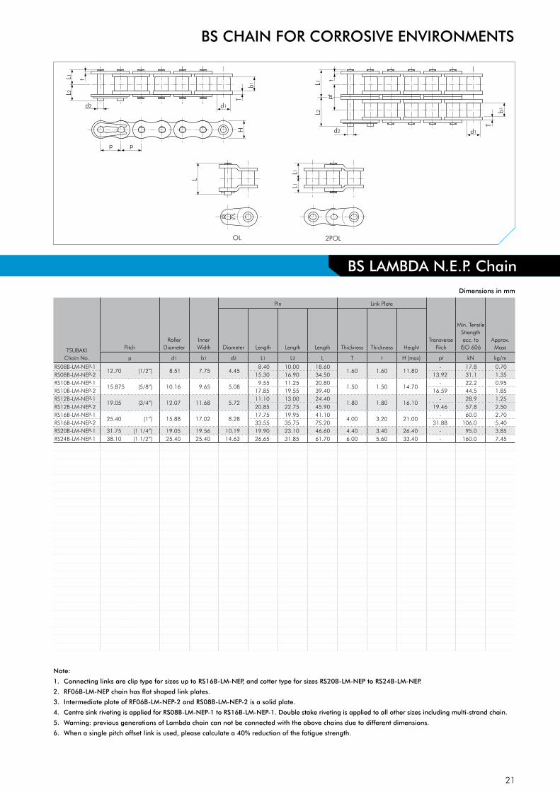
BS LAMBDA N.E.P. Chain
BS CHAIN FOR CORROSIVE ENVIRONMENTS
TSUBAKIChain No.
PitchRoller
DiameterInnerWidth
Pin Link Plate
TransversePitch
Min. Tensile Strengthacc. to
ISO 606Approx.MassDiameter Length Length Length Thickness Thickness Height
p d1 b1 d2 L1 L2 L T t H (max) pt kN kg/m
RS08B-LM-NEP-112.70 (1/2”) 8.51 7.75 4.45
8.40 10.00 18.601.60 1.60 11.80
- 17.8 0.70RS08B-LM-NEP-2 15.30 16.90 34.50 13.92 31.1 1.35RS10B-LM-NEP-1
15.875 (5/8”) 10.16 9.65 5.08 9.55 11.25 20.80
1.50 1.50 14.70- 22.2 0.95
RS10B-LM-NEP-2 17.85 19.55 39.40 16.59 44.5 1.85RS12B-LM-NEP-1
19.05 (3/4”) 12.07 11.68 5.7211.10 13.00 24.40
1.80 1.80 16.10- 28.9 1.25
RS12B-LM-NEP-2 20.85 22.75 45.90 19.46 57.8 2.50RS16B-LM-NEP-1
25.40 (1”) 15.88 17.02 8.2817.75 19.95 41.10
4.00 3.20 21.00- 60.0 2.70
RS16B-LM-NEP-2 33.55 35.75 75.20 31.88 106.0 5.40RS20B-LM-NEP-1 31.75 (1 1/4”) 19.05 19.56 10.19 19.90 23.10 46.60 4.40 3.40 26.40 - 95.0 3.85RS24B-LM-NEP-1 38.10 (1 1/2”) 25.40 25.40 14.63 26.65 31.85 61.70 6.00 5.60 33.40 - 160.0 7.45
L2
L1
d2 d1
p
H
T
t
p
b1
d2 d1
T
b1
L2
L1 t
pt
OL
L
L1
L1
2POL
Dimensions in mm
Note:
1. Connecting links are clip type for sizes up to RS16B-LM-NEP, and cotter type for sizes RS20B-LM-NEP to RS24B-LM-NEP.
2. RF06B-LM-NEP chain has flat shaped link plates.
3. Intermediate plate of RF06B-LM-NEP-2 and RS08B-LM-NEP-2 is a solid plate.
4. Centre sink riveting is applied for RS08B-LM-NEP-1 to RS16B-LM-NEP-1. Double stake riveting is applied to all other sizes including multi-strand chain.
5. Warning: previous generations of Lambda chain can not be connected with the above chains due to different dimensions.
6. When a single pitch offset link is used, please calculate a 40% reduction of the fatigue strength.

22
BS N.E.P. Chain
L2
L1
d2 d1
p
H
T
t
p
b1
d2 d1
T
b1
L2
L1 t
pt
OL
L
L1
L1
2POL
Dimensions in mm
Note:
1. Connecting links are clip type for sizes up to RS16B-NEP, and cotter type for sizes RS20B-NEP to RS24B-NEP.
2. RF06B-NEP chain has flat-shaped link plates.
3. Intermediate plate of multi strand RF06B-NEP-2 and RS08B-NEP-2 chain is a solid plate.
4. Center sink riveting is applied to RS08B-NEP-1 to RS16B-NEP-1 single strand chain.
5. Double stake riveting is applied to all other sizes including multi-strand chain.
6. When a single pitch offset link is used, please calculate a 40% reduction of the fatigue strength.
BS CHAIN FOR CORROSIVE ENVIRONMENTS
TSUBAKIChain No.
PitchRoller
DiameterInner Width
Pin Link Plate
Transverse Pitch
Min. Tensile
Strengthacc. to
ISO 606
Min. Tensile
Strengthacc. to Tsubaki
Approx. MassDiameter Length Length Length Thickness Thickness Height
p d1 b1 d2 L1 L2 L T t H (max) pt kN kN kg/mRF06B-NEP-1
9.525 (3/8”) 6.35 5.72 3.276.10 7.70 15.10
1.30 1.00 8.20- 8.9 9.0 0.39
RF06B-NEP-2 11.20 12.80 25.90 10.24 16.9 17.0 0.75RS08B-NEP-1
12.70 (1/2”) 8.51 7.75 4.458.40 10.00 18.60
1.60 1.60 11.80- 17.8 19.0 0.70
RS08B-NEP-2 15.30 16.90 34.50 13.92 31.1 32.0 1.35RS10B-NEP-1
15.875 (5/8”) 10.16 9.65 5.089.55 11.25 20.80
1.50 1.50 14.70- 22.2 23.0 0.95
RS10B-NEP-2 17.85 19.55 39.40 16.59 44.5 44.5 1.85RS12B-NEP-1
19.05 (3/4”) 12.07 11.68 5.7211.10 13.00 24.40
1.80 1.80 16.10- 28.9 31.0 1.25
RS12B-NEP-2 20.85 22.75 45.90 19.46 57.8 61.0 2.50RS16B-NEP-1
25.40 (1”) 15.88 17.02 8.2817.75 19.95 43.30
4.00 3.20 21.00- 60.0 70.0 2.70
RS16B-NEP-2 33.55 35.75 75.20 31.88 106.0 128.0 5.40RS20B-NEP-1
31.75 (1 1/4”) 19.05 19.56 10.1919.90 23.10 48.20
4.40 3.40 26.00- 95.0 98.1 3.85
RS20B-NEP-2 38.25 41.45 84.60 36.45 170.0 197.0 7.65RS24B-NEP-1 38.10 (1 1/2”) 25.40 25.40 14.63 26.65 31.85 64.30 6.00 5.60 33.40 - 160.0 167.0 7.45

23
BS CHAIN FOR CORROSIVE ENVIRONMENTS
L2
L1
d2 d1
p
H
T
t
p
b1
d2 d1
T
b1
L2
L1 t
pt
OL
L
L1
L1
2POLd2 d1
T
b1 L2
L1
t pt
pt
Dimensions in mm
Note:
1. Connecting links are clip type for sizes up to RS16B-NP, and cotter type for sizes RS16B-NP to RS32B-NP.
2. RF06B-NP chain has flat-shaped link plates.
3. Intermediate plate of multi strand RF06B-NP-2 and RS08B-NP-2 chain is a solid plate.
4. Center sink riveting is applied to RS08B-NP-1 to RS16B-NP-1 single strand chain.
5. Double stake riveting is applied to all other sizes including multi-strand chain.
6. When a single pitch offset link is used, please calculate a 40% reduction of the fatigue strength.
BS NP Chain
TSUBAKIChain No.
PitchRoller
DiameterInner Width
Pin Link Plate
Transverse Pitch
Min. Tensile
Strengthacc. to
ISO 606
Min. Tensile
Strengthacc. to Tsubaki
Approx. MasDiameter Length Length Length Thickness Thickness Height
p d1 b1 d2 L1 L2 L T t H (max) pt kN kN kg/mRF06B-NP-1
9.525 (3/8”) 6.35 5.72 3.276.10 7.70 15.10
1.30 1.00 8.20- 8.9 9.0 0.39
RF06B-NP-2 11.20 12.80 - 10.24 16.9 17.0 0.75RF06B-NP-3 16.40 17.90 - 10.24 24.9 24.9 1.11RS08B-NP-1
12.70 (1/2”) 8.51 7.75 4.458.40 10.00 18.60
1.60 1.60 11.80- 17.8 19.0 0.70
RS08B-NP-2 15.30 16.90 34.50 13.92 31.1 32.0 1.35RS08B-NP-3 22.25 23.85 48.40 13.92 44.5 47.5 2.00RS10B-NP-1
15.875 (5/8”) 10.16 9.65 5.089.55 11.25 20.80
1.50 1.50 14.70- 22.2 23.0 0.95
RS10B-NP-2 17.85 19.55 39.40 16.59 44.5 44.5 1.85RS10B-NP-3 26.15 27.85 56.00 16.59 66.7 66.8 2.80RS12B-NP-1
19.05 (3/4”) 12.07 11.68 5.7211.10 13.00 24.40
1.80 1.80 16.10- 28.9 31.0 1.25
RS12B-NP-2 20.85 22.75 45.90 19.46 57.8 61.0 2.50RS12B-NP-3 30.60 32.50 65.40 19.46 86.7 92.0 3.80RS16B-NP-1
25.40 (1”) 15.88 17.02 8.2817.75 19.95 41.10
4.00 3.20 21.00- 60.0 70.0 2.70
RS16B-NP-2 33.55 35.75 75.20 31.88 106.0 128.0 5.40RS20B-NP-1
31.75 (1 1/4”) 19.05 19.56 10.1919.90 23.10 46.60
4.40 3.40 26.00- 95.0 98.1 3.85
RS20B-NP-2 38.25 41.45 84.60 36.45 170.0 197.0 7.65RS24B-NP-1
38.10 (1 1/2”) 25.40 25.40 14.6326.65 31.85 61.70
6.00 5.60 33.40- 160.0 167.0 7.45
RS24B-NP-2 50.80 56.00 112.80 48.36 280.0 335.0 14.65RS28B-NP-1
44.45 (1 3/4”) 27.94 30.99 15.9032.45 37.45 74.40
7.50 6.30 36.40- 200.0 200.0 9.45
RS28B-NP-2 62.15 67.15 136.60 59.56 360.0 374.0 18.80RS32B-NP-1
50.80 (2”) 29.21 30.99 17.8132.10 37.70 73.30
7.00 6.30 42.20- 250.0 255.0 10.25
RS32B-NP-2 61.25 66.85 134.50 58.55 450.0 485.0 20.10

24
Special Coated PinSpecial Oil ImpregnatedSintered Bush
Ring Coin
Roller
Technical EvolutionAs a pioneer in the lube-free chain market, TSUBAKI will reveal some of the key elements behind ANSI LAMBDA’s outstanding performance:
Sintered BushA special oil impregnated sintered bush in combination with a special coated pin for long-term internal lubrication is the secret of TSUBAKI ANSI LAMBDA’s long economic life and wear resistance.
Patented Ring Coining ProcessBreakage of the chains connecting link is no issue at TSUBAKI thanks to this unique feature. By applying the patented Ring Coining process, TSUBAKI generates a cold deformation around the pin hole of the connecting link plate. This results in residual stress around the pin hole and thereby adds strength. By using this process transmission capacity is increased to 100% of the base chain.
Special EnvironmentsTSUBAKI ANSI LAMBDA has outstanding performance in tempe-ratures up to +150°C.
For temperatures above +150°C: Due to the special NSF-H1 certified lubrication impregnated bushes, TSUBAKI ANSI LAMBDA KF Series is usable in a wide temperature range (from -10°C to +230°C), and for food product applications while at the same time being kind to the environment.Please consult TSUBAKI for more detailed information.
AdvantagesTSUBAKI has enhanced the ANSI LAMBDA with the following ad-vantages:
Save Maintenance CostsNo expensive labour costs as it is not required to manually lubri-cate this chain.
Save Purchasing CostsLower frequency of purchasing due to the high quality of the chain and its long economic life. No purchasing of lubricants or lubrication systems necessary.
Higher Productivity No unforeseen downtime due to chain breakdown.Less time required for maintenance and therefore more time for production.
Environmental FriendlyApplications run clean thus reducing the risk of contaminating products, machines, floor etc.
Inter-Changeability
Sprockets:Only simplex ANSI roller chain sprockets are interchangeable. Multi strand sprockets need to be customised due to the thickness of the roller link plates. Due to the extended lifetime of ANSI LAMBDA chain, TSUBAKI advises to install sprockets with hardened teeth in every LAMBDA application.
ANSI LAMBDA LUBE FREE ROLLER CHAIN
TSUBAKI’s LAMBDA Chains were the first in the industry to use a special oil
impregnated bush. Since their launch in 1988, they have been adopted for diverse
industries and applications, and their performance has been highly rated. TSUBAKI
has a wide line-up of lube-free, long life products that help customers reduce costs.
Fig. 14 Basic Construction
25
L2
L1
d2 d1
p
H
T
t
p
b1
d2 d1
T
b1L2
L1 t
pt
OL
L
L1
L1
2POL
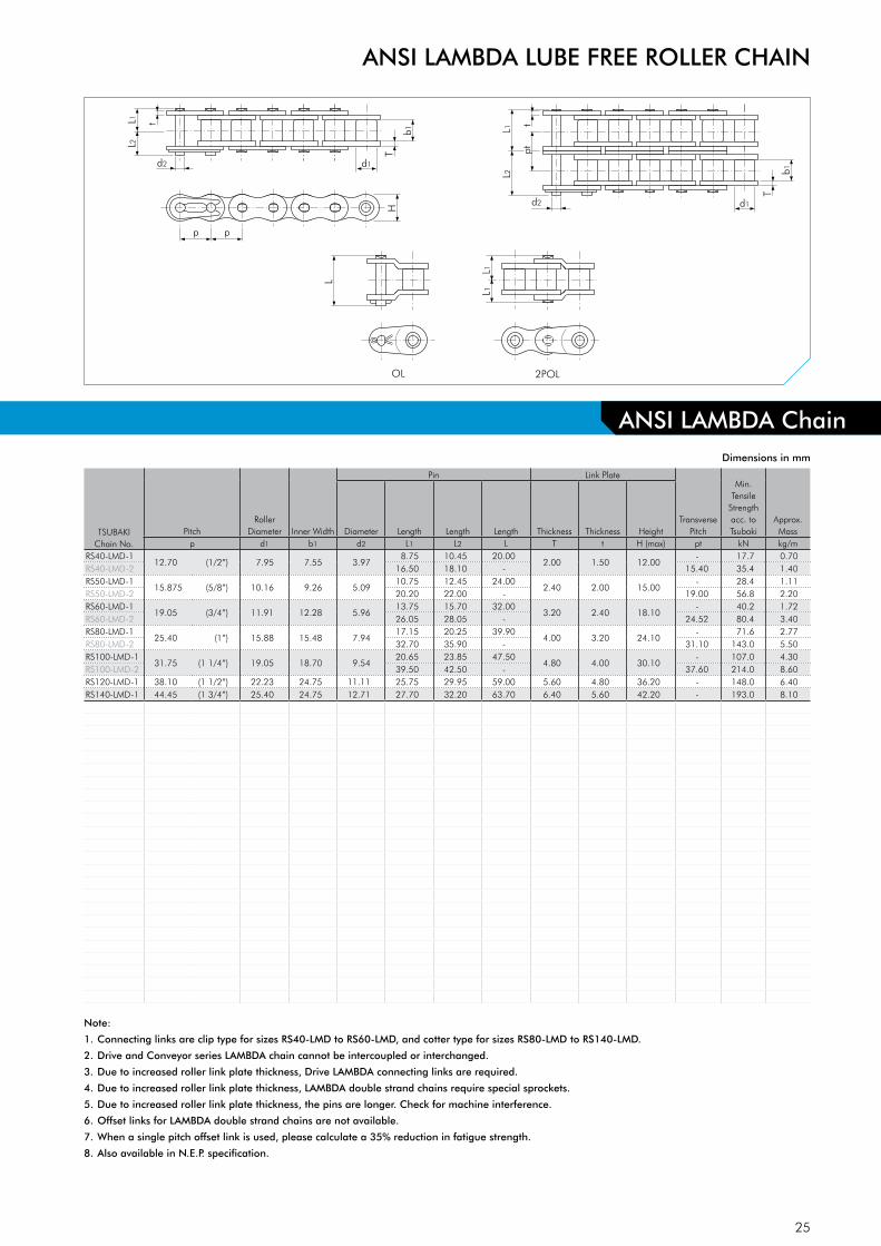
ANSI LAMBDA LUBE FREE ROLLER CHAIN
Dimensions in mm
Note:
1. Connecting links are clip type for sizes RS40-LMD to RS60-LMD, and cotter type for sizes RS80-LMD to RS140-LMD.
2. Drive and Conveyor series LAMBDA chain cannot be intercoupled or interchanged.
3. Due to increased roller link plate thickness, Drive LAMBDA connecting links are required.
4. Due to increased roller link plate thickness, LAMBDA double strand chains require special sprockets.
5. Due to increased roller link plate thickness, the pins are longer. Check for machine interference.
6. Offset links for LAMBDA double strand chains are not available.
7. When a single pitch offset link is used, please calculate a 35% reduction in fatigue strength.
8. Also available in N.E.P. specification.
ANSI LAMBDA Chain
TSUBAKIChain No.
PitchRoller
Diameter Inner Width
Pin Link Plate
Transverse Pitch
Min. Tensile
Strength acc. to Tsubaki
Approx. MassDiameter Length Length Length Thickness Thickness Height
p d1 b1 d2 L1 L2 L T t H (max) pt kN kg/mRS40-LMD-1
12.70 (1/2”) 7.95 7.55 3.978.75 10.45 20.00
2.00 1.50 12.00- 17.7 0.70
RS40-LMD-2 16.50 18.10 - 15.40 35.4 1.40RS50-LMD-1
15.875 (5/8”) 10.16 9.26 5.0910.75 12.45 24.00
2.40 2.00 15.00- 28.4 1.11
RS50-LMD-2 20.20 22.00 - 19.00 56.8 2.20RS60-LMD-1
19.05 (3/4”) 11.91 12.28 5.9613.75 15.70 32.00
3.20 2.40 18.10- 40.2 1.72
RS60-LMD-2 26.05 28.05 - 24.52 80.4 3.40RS80-LMD-1
25.40 (1”) 15.88 15.48 7.9417.15 20.25 39.90
4.00 3.20 24.10- 71.6 2.77
RS80-LMD-2 32.70 35.90 - 31.10 143.0 5.50RS100-LMD-1
31.75 (1 1/4”) 19.05 18.70 9.5420.65 23.85 47.50
4.80 4.00 30.10- 107.0 4.30
RS100-LMD-2 39.50 42.50 - 37.60 214.0 8.60RS120-LMD-1 38.10 (1 1/2”) 22.23 24.75 11.11 25.75 29.95 59.00 5.60 4.80 36.20 - 148.0 6.40RS140-LMD-1 44.45 (1 3/4”) 25.40 24.75 12.71 27.70 32.20 63.70 6.40 5.60 42.20 - 193.0 8.10

26
Technical Evolution
All ANSI Chains Are Not Created EqualANSI defines minimum threshold standards: acceptable, but they won’t improve your bottom line. TSUBAKI ANSI G7 Chains set the bar higher with design innovations that deliver solid results!
Solid Lube Groove Bush - Our Latest InnovationUnlike curled bush, TSUBAKI SOLID Lube Groove Bush does not have a split. This means that oil cannot leak from the bearing area as a result of that type of manufacturing process. Additional to that innovation TSUBAKI developed a unique process to add grooves to the inner surface of the solid bush. This lube groove process ensures longer and better lubrication which results in an extended chain life.
The Lube Groove Bush is available in ANSI sizes RS80 through RS140, perfectly sized for the most demanding applications.
Fig. 15 Solid Lube Groove Bush
AdvantagesTSUBAKI has enhanced the ANSI G7 with the following advan-tages:
Save Operating Costs and Reduce Downtime Normally, ANSI chains are removed or replaced due to elon-gation caused by wear in the pin-bush joint. The patented Lube Groove retains lubricant right where it’s needed: in the pin-bush joint. In many applications you’ll notice a significant difference in maintenance, operating, and replacement costs due to the increased reliability of the ANSI G7 chains.
Increased kW RatingTransmission capacity has been increased by applying the paten-ted TSUBAKI Ring Coining process on the connecting link plate.
For easy assembling the pin and link plate of a connecting link are slip fit. In general, this type of connecting link has a 20% lower fatigue strength than the chain itself. However, TSUBAKI developed a special process to eliminate that loss of Fatigue Strength and still satisfy the customers demand for easy assem-bly: the patented Ring Coining process. By applying the patented Ring Coining process, TSUBAKI generates a cold deformation around the pin hole of the connecting link plate. This results in residual stress around the pin hole and thereby adds strength. By using this process transmission capacity is increased to 100% of that of the base chain.
Constant Quality LevelIn pursuit of outstanding quality, every TSUBAKI chain is made of a special steel alloy developed by the TSUBAKI Engineering Department. Besides that, TSUBAKI produces the ANSI G7 under highly con-trolled conditions in its advanced heat treatment facilities. This, in combination with the TSUBAKI fatigue strength confirmation tests, ensures that our customers can always rely on a constant level of TSUBAKI quality.
Customised Pre-Lubrication ServiceProper lubrication is the key to extend the life and improve the performance of a chain. In order to get the best performance in general applications (-10 to +60°C), all ANSI G7 drive chains are pre-lubricated. For special applications, TSUBAKI can provide chains which are pre-lubricated with a special lubricant on customer demand:
• High temperature • Low temperature • Food safe • Outdoor exposure• Dusty environment
Please consult TSUBAKI for more detailed information.
ANSI G7 STANDARD ROLLER CHAIN
TSUBAKI’s 7th model upgrade, celebrating 90 years of quality. Pursuing the ultimate
in quality, TSUBAKI has created the world’s highest standard of roller chain.
27
L2
L1
d2 d1
p
H
T
T
p
b1
L2
L1
d2 d1
T
T
b1
pt
L2
L1
d2 d1
T
T
b1
pt
pt
OL
L
L1
L1
2POL
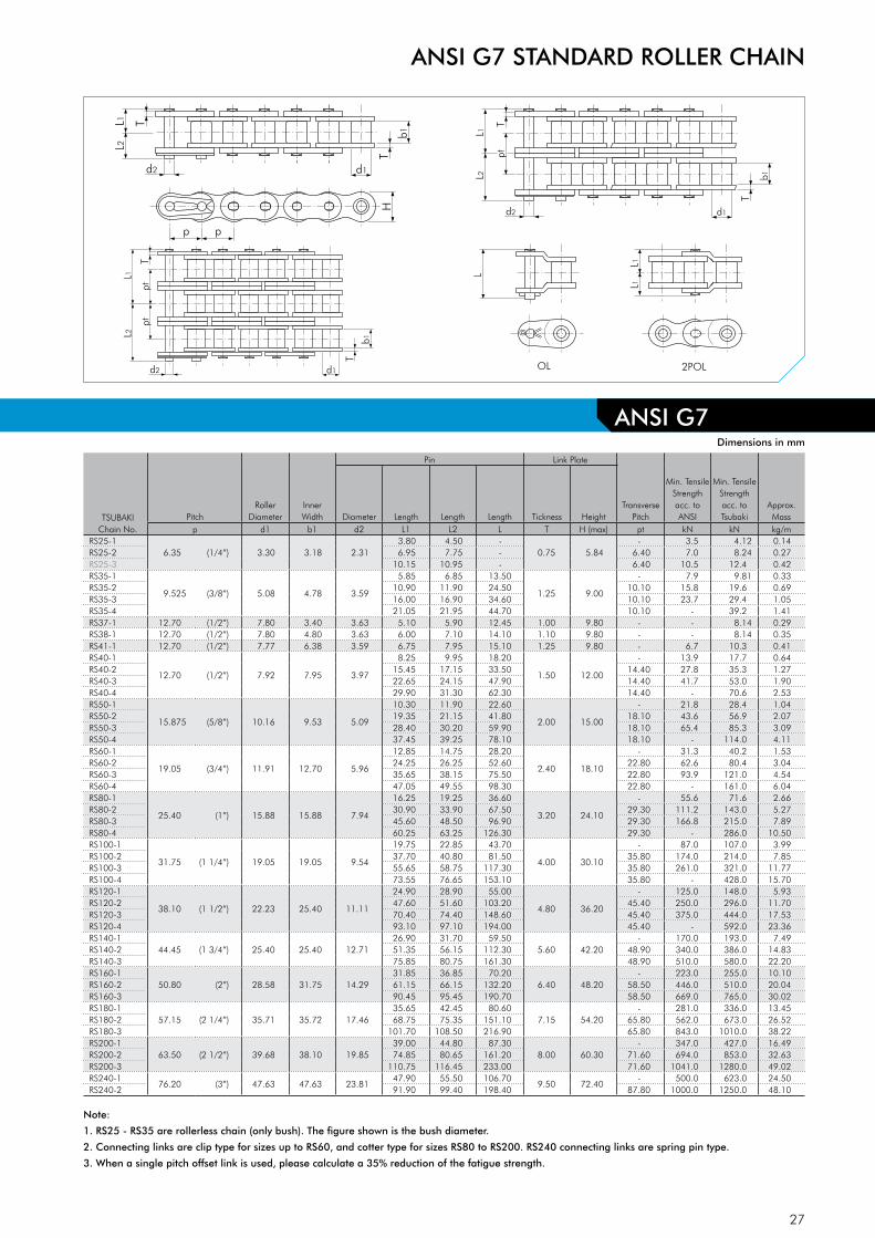
ANSI G7 STANDARD ROLLER CHAIN
ANSI G7 Dimensions in mm
Note:
1. RS25 - RS35 are rollerless chain (only bush). The figure shown is the bush diameter.
2. Connecting links are clip type for sizes up to RS60, and cotter type for sizes RS80 to RS200. RS240 connecting links are spring pin type.
3. When a single pitch offset link is used, please calculate a 35% reduction of the fatigue strength.
TSUBAKIChain No.
PitchRoller
DiameterInner Width
Pin Link Plate
Transverse Pitch
Min. Tensile Strengthacc. to ANSI
Min. Tensile Strengthacc. to Tsubaki
Approx. MassDiameter Length Length Length Tickness Height
p d1 b1 d2 L1 L2 L T H (max) pt kN kN kg/mRS25-1
6.35 (1/4”) 3.30 3.18 2.313.80 4.50 -
0.75 5.84- 3.5 4.12 0.14
RS25-2 6.95 7.75 - 6.40 7.0 8.24 0.27RS25-3 10.15 10.95 - 6.40 10.5 12.4 0.42RS35-1
9.525 (3/8”) 5.08 4.78 3.59
5.85 6.85 13.50
1.25 9.00
- 7.9 9.81 0.33RS35-2 10.90 11.90 24.50 10.10 15.8 19.6 0.69RS35-3 16.00 16.90 34.60 10.10 23.7 29.4 1.05RS35-4 21.05 21.95 44.70 10.10 - 39.2 1.41RS37-1 12.70 (1/2”) 7.80 3.40 3.63 5.10 5.90 12.45 1.00 9.80 - - 8.14 0.29RS38-1 12.70 (1/2”) 7.80 4.80 3.63 6.00 7.10 14.10 1.10 9.80 - - 8.14 0.35RS41-1 12.70 (1/2”) 7.77 6.38 3.59 6.75 7.95 15.10 1.25 9.80 - 6.7 10.3 0.41RS40-1
12.70 (1/2”) 7.92 7.95 3.97
8.25 9.95 18.20
1.50 12.00
- 13.9 17.7 0.64RS40-2 15.45 17.15 33.50 14.40 27.8 35.3 1.27RS40-3 22.65 24.15 47.90 14.40 41.7 53.0 1.90RS40-4 29.90 31.30 62.30 14.40 - 70.6 2.53RS50-1
15.875 (5/8”) 10.16 9.53 5.09
10.30 11.90 22.60
2.00 15.00
- 21.8 28.4 1.04RS50-2 19.35 21.15 41.80 18.10 43.6 56.9 2.07RS50-3 28.40 30.20 59.90 18.10 65.4 85.3 3.09RS50-4 37.45 39.25 78.10 18.10 - 114.0 4.11RS60-1
19.05 (3/4”) 11.91 12.70 5.96
12.85 14.75 28.20
2.40 18.10
- 31.3 40.2 1.53RS60-2 24.25 26.25 52.60 22.80 62.6 80.4 3.04RS60-3 35.65 38.15 75.50 22.80 93.9 121.0 4.54RS60-4 47.05 49.55 98.30 22.80 - 161.0 6.04RS80-1
25.40 (1”) 15.88 15.88 7.94
16.25 19.25 36.60
3.20 24.10
- 55.6 71.6 2.66RS80-2 30.90 33.90 67.50 29.30 111.2 143.0 5.27RS80-3 45.60 48.50 96.90 29.30 166.8 215.0 7.89RS80-4 60.25 63.25 126.30 29.30 - 286.0 10.50RS100-1
31.75 (1 1/4”) 19.05 19.05 9.54
19.75 22.85 43.70
4.00 30.10
- 87.0 107.0 3.99RS100-2 37.70 40.80 81.50 35.80 174.0 214.0 7.85RS100-3 55.65 58.75 117.30 35.80 261.0 321.0 11.77RS100-4 73.55 76.65 153.10 35.80 - 428.0 15.70RS120-1
38.10 (1 1/2”) 22.23 25.40 11.11
24.90 28.90 55.00
4.80 36.20
- 125.0 148.0 5.93RS120-2 47.60 51.60 103.20 45.40 250.0 296.0 11.70RS120-3 70.40 74.40 148.60 45.40 375.0 444.0 17.53RS120-4 93.10 97.10 194.00 45.40 - 592.0 23.36RS140-1
44.45 (1 3/4”) 25.40 25.40 12.7126.90 31.70 59.50
5.60 42.20- 170.0 193.0 7.49
RS140-2 51.35 56.15 112.30 48.90 340.0 386.0 14.83RS140-3 75.85 80.75 161.30 48.90 510.0 580.0 22.20RS160-1
50.80 (2”) 28.58 31.75 14.2931.85 36.85 70.20
6.40 48.20- 223.0 255.0 10.10
RS160-2 61.15 66.15 132.20 58.50 446.0 510.0 20.04RS160-3 90.45 95.45 190.70 58.50 669.0 765.0 30.02RS180-1
57.15 (2 1/4”) 35.71 35.72 17.4635.65 42.45 80.60
7.15 54.20- 281.0 336.0 13.45
RS180-2 68.75 75.35 151.10 65.80 562.0 673.0 26.52RS180-3 101.70 108.50 216.90 65.80 843.0 1010.0 38.22RS200-1
63.50 (2 1/2”) 39.68 38.10 19.8539.00 44.80 87.30
8.00 60.30- 347.0 427.0 16.49
RS200-2 74.85 80.65 161.20 71.60 694.0 853.0 32.63RS200-3 110.75 116.45 233.00 71.60 1041.0 1280.0 49.02RS240-1
76.20 (3”) 47.63 47.63 23.8147.90 55.50 106.70
9.50 72.40- 500.0 623.0 24.50
RS240-2 91.90 99.40 198.40 87.80 1000.0 1250.0 48.10

28
Corrosion Resistant Chain(Stainless Steel base)
ANSI PC Engineering Plastic Combination ChainThe pins and pin link plates of these chains are made of SUS304 equivalent (spring clips SUS301). Engineering Plastic (white) is used for the inner link. This combination makes it a lube-free, low noise (5 dB lower than ANSI standard roller chain) and light-weight chain (50% lighter than ANSI standard roller chain). Wor-king temperature range: -20°C to +80°C. For details on corro-sion resistance, please check out the table in the back of this catalogue as a basic guide.
ANSI SS Stainless Steel ChainAll basic components of this chain are made of SUS304 equiva-lent Stainless Steel (except the spring clips, which are made of SUS301). This chain can be used in special environments such as under water, acidic and alkaline applications. It can also be used in high and low temperatures (-20°C to +400°C). SUS304 equivalent is only marginally magnetic, due to the cold-forging process. For details on corrosion resistance, please check out the table in the back of this catalogue as a basic guide.
ANSI AS Stainless Steel ChainThe pins and rollers of this roller chain are made of precipitation-hardened, tempered stainless steel. The link plates and the bu-shes are made of SUS304 equivalent stainless steel (spring clips are SUS301). The Maximum Allowable Load is 1.5 times that of ANSI SS chain. Corrosion resistance is slightly lower than standard SS chain. This chain is suitable where corrosion and heat resistance is required in a heavy duty drive application and where a smaller ANSI SS chain is preferred. Magnetism exists due to the use of precipitation-hardened stainless steel. The wor-king temperature range: -20°C to +400°C.
Corrosion Protected Chain(Carbon Steel base)
ANSI N.E.P. New Environmental Plating ChainANSI N.E.P. Chain is a TSUBAKI ANSI G7 chain that has undergone a special surface treatment. The link plates, bushes and pins have a special three stage layer applied in order to provide the maximum protection from the operating or environmental condi-tions. (Spring clips are SUS301). N.E.P. Rollers have a special coa-ting designed to resist the corrosive conditions as well as the se-vere dynamic contact between roller and sprocket.
This chain is suitable for use in environments exposed to sea-water, acid-rain and other adverse weather conditions. This chain does not contain any chemically hazardous substances such as Hexavalent Chromium, Lead, Cadmium and Mercury as regula-ted by RoHS√. The kilowatt ratings are the same as those of the corresponding ANSI G7 chain. Working temperature range is: -10°C to +150°C. Above +60°C a special high-temperature lubrication is required. Of course, ANSI LAMBDA N.E.P. chain is also available.
ANSI NP Nickel Plated ChainANSI NP Chain is a TSUBAKI ANSI G7 chain that has been plated with Nickel. NP chain has a light corrosion resistance and an attractive appearance. NP chain is suitable for outdoor con-ditions exposed to water. There is a 15% reduction in Maximum Allowable Load compared to the corresponding ANSI G7 chain, so please take this into account when making your chain selec-tion. The working temperature range is: -10°C to +60°C. Of course, ANSI LAMBDA NP chain is also available.
√ RoHS = Restriction of Hazardous Substances
ANSI CHAIN FOR CORROSIVE ENVIRONMENTS
Whether your operation requires a sanitary environment, is exposed to corrosive
chemicals, is heated to extreme temperatures, runs through a freezer, is exposed to
the outdoors or is affected by excessive moisture: our specially designed and tested
chains will outlast your current chains and contribute to a cost effective application.
29
L2L1
d2
p
HT
t
p
b1
d1
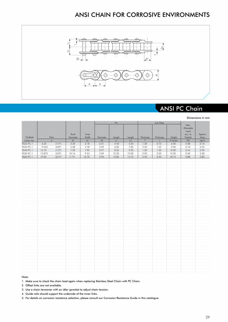
ANSI CHAIN FOR CORROSIVE ENVIRONMENTS
ANSI PC Chain
TSUBAKIChain No.
PitchBush
DiameterInnerWidth
Pin Link PlateMax.
Allowable Load
acc. to Tsubaki
Approx. MassDiameter Length Length Thickness Thickness Height
p d1 b1 d2 L1 L2 T t H (max) kN kg/mRS25-PC-1 6.35 (1/4”) 3.30 3.18 2.31 4.50 5.50 1.30 0.75 6.00 0.08 0.10RS35-PC-1 9.525 (3/8”) 5.08 4.78 3.59 6.85 7.85 2.20 1.25 9.00 0.18 0.22RS40-PC-1 12.70 (1/2”) 7.92 7.95 3.97 8.25 9.95 1.50 1.50 12.00 0.44 0.39RS50-PC-1 15.875 (5/8”) 10.16 9.53 5.09 10.30 12.00 2.00 2.00 15.00 0.69 0.58RS60-PC-1 19.05 (3/4”) 11.91 12.70 5.96 12.85 14.75 2.40 2.40 18.10 0.88 0.82
Dimensions in mm
Note:
1. Make sure to check the chain load again when replacing Stainless Steel Chain with PC Chain.
2. Offset links are not available.
3. Use a chain tensioner with an idler sprocket to adjust chain tension.
4. Guide rails should support the underside of the inner links.
5. For details on corrosion resistance selection, please consult our Corrosion Resistance Guide in this catalogue.
30
L2
L1
d2 d1
p
H
T
T
p
b1
d2 d1
T
b1
L2
L1 T
pt
OL
L
L1
L1
2POL
Dimensions in mm
Note:
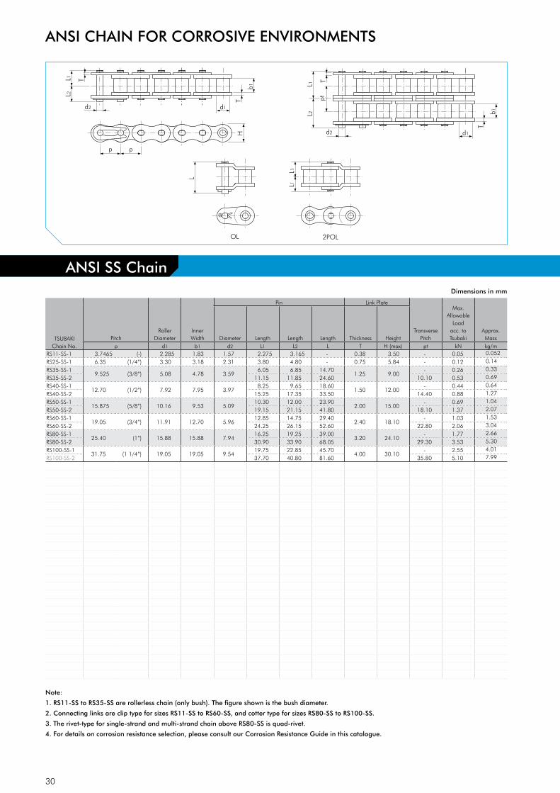
1. RS11-SS to RS35-SS are rollerless chain (only bush). The figure shown is the bush diameter.
2. Connecting links are clip type for sizes RS11-SS to RS60-SS, and cotter type for sizes RS80-SS to RS100-SS.
3. The rivet-type for single-strand and multi-strand chain above RS80-SS is quad-rivet.
4. For details on corrosion resistance selection, please consult our Corrosion Resistance Guide in this catalogue.
ANSI SS Chain
ANSI CHAIN FOR CORROSIVE ENVIRONMENTS
TSUBAKIChain No.
PitchRoller
DiameterInner Width
Pin Link Plate
Transverse Pitch
Max. Allowable
Loadacc. to Tsubaki
Approx. MassDiameter Length Length Length Thickness Height
p d1 b1 d2 L1 L2 L T H (max) pt kN kg/mRS11-SS-1 3.7465 (-) 2.285 1.83 1.57 2.275 3.165 - 0.38 3.50 - 0.05 0.052
RS25-SS-1 6.35 (1/4”) 3.30 3.18 2.31 3.80 4.80 - 0.75 5.84 - 0.12 0.14
RS35-SS-19.525 (3/8”) 5.08 4.78 3.59
6.05 6.85 14.701.25 9.00
- 0.26 0.33
RS35-SS-2 11.15 11.85 24.60 10.10 0.53 0.69
RS40-SS-1 12.70 (1/2”) 7.92 7.95 3.97
8.25 9.65 18.601.50 12.00
- 0.44 0.64
RS40-SS-2 15.25 17.35 33.50 14.40 0.88 1.27
RS50-SS-1 15.875 (5/8”) 10.16 9.53 5.09
10.30 12.00 23.902.00 15.00
- 0.69 1.04
RS50-SS-2 19.15 21.15 41.80 18.10 1.37 2.07
RS60-SS-1 19.05 (3/4”) 11.91 12.70 5.96
12.85 14.75 29.402.40 18.10
- 1.03 1.53
RS60-SS-2 24.25 26.15 52.60 22.80 2.06 3.04
RS80-SS-1 25.40 (1”) 15.88 15.88 7.94
16.25 19.25 39.003.20 24.10
- 1.77 2.66
RS80-SS-2 30.90 33.90 68.05 29.30 3.53 5.30
RS100-SS-1 31.75 (1 1/4”) 19.05 19.05 9.54
19.75 22.85 45.70 4.00 30.10
- 2.55 4.01
RS100-SS-2 37.70 40.80 81.60 35.80 5.10 7.99

31
L2
L1
d2 d1
p
H
T
T
p
b1
OL
L
L1
L1
2POL
ANSI AS Chain
TSUBAKIChain No.
PitchRoller
DiameterInner Width
Pin Link PlateMax.
Allowable Load
acc. to Tsubaki
Approx. MassDiameter Length Length Length Thickness Height
p d1 b1 d2 L1 L2 L T H (max) kN kg/mRS35-AS-1 9.525 (3/8”) 5.08 4.78 3.59 5.85 6.85 14.70 1.25 9.00 0.39 0.33RS40-AS-1 12.70 (1/2”) 7.92 7.95 3.97 8.25 9.95 18.60 1.50 12.00 0.69 0.64RS50-AS-1 15.875 (5/8”) 10.16 9.53 5.09 10.30 12.00 23.90 2.00 15.00 1.03 1.04RS60-AS-1 19.05 (3/4”) 11.91 12.70 5.96 12.85 14.75 29.40 2.40 18.10 1.57 1.53RS80-AS-1 25.40 (1”) 15.88 15.88 7.94 16.25 19.25 39.00 3.20 24.10 2.65 2.66
Dimensions in mm
Note:
1. Connecting links are clip type for sizes RS35-AS to RS60-AS, and cotter type for size RS80-AS.
2. RS35-AS is rollerless chain (only bush). The figure shown is the bush diameter.
3. For details on corrosion resistance selection, please consult our Corrosion Resistance Guide in this catalogue.
ANSI CHAIN FOR CORROSIVE ENVIRONMENTS

32
L2
L1
d2 d1
p
H
T
t
p
b1
OL
L
L1
L1
2POL
Dimensions in mm
Note:
1. Connecting links are clip type for sizes RS40-LMD-NEP to RS60-LMD-NEP, and cotter type for sizes RS80-LMD-NEP to RS140-LMD-NEP.
2. Drive and Conveyor series LAMBDA chain cannot be intercoupled or interchanged.
3. Due to increased roller link plate thickness, Drive LAMBDA connecting links are required.
4. Due to increased roller link plate thickness, the pins are longer. Check for machine interference.
5. When a single pitch offset link is used, please calculate a 35% reduction in fatigue strength.
ANSI CHAIN FOR CORROSIVE ENVIRONMENTS
ANSI LAMBDA N.E.P. Chain
TSUBAKIChain No.
PitchRoller
DiameterInner Width
Pin Link Plate
Min. Tensile Strength acc. to Tsubaki
Approx. MassDiameter Length Length Length Thickness Thickness Height
p d1 b1 d2 L1 L2 L T t H (max) kN kg/mRS40-LMD-NEP-1 12.70 (1/2”) 7.95 7.55 3.97 8.75 10.45 20.00 2.00 1.50 12.00 17.7 0.70RS50-LMD-NEP-1 15.875 (5/8”) 10.16 9.26 5.09 10.75 12.45 24.00 2.40 2.00 15.00 28.4 1.11RS60-LMD-NEP-1 19.05 (3/4”) 11.91 12.28 5.96 13.70 15.70 32.00 3.20 2.40 18.10 40.2 1.72RS80-LMD-NEP-1 25.40 (1”) 15.88 15.48 7.94 17.15 20.25 39.90 4.00 3.20 24.10 71.6 2.77RS100-LMD-NEP-1 31.75 (1 1/4”) 19.05 18.70 9.54 20.65 23.85 47.50 4.80 4.00 30.10 107.0 4.30RS120-LMD-NEP-1 38.10 (1 1/2”) 22.23 24.75 11.11 25.75 29.95 59.00 5.60 4.80 36.20 148.0 6.40RS140-LMD-NEP-1 44.45 (1 3/4”) 25.40 24.75 12.71 27.70 32.20 63.70 6.40 5.60 42.20 193.0 8.10
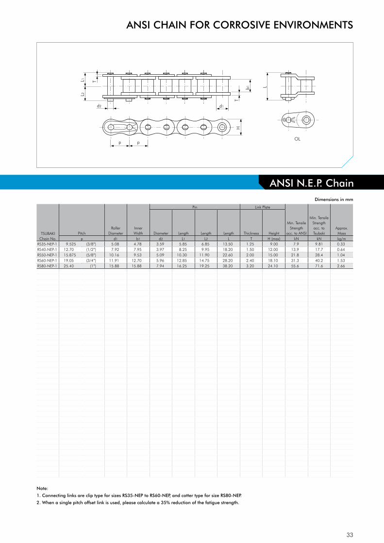
33
ANSI N.E.P. ChainANSI N.E.P. Chain
ANSI CHAIN FOR CORROSIVE ENVIRONMENTS
L2
L1
d2 d1
p
H
T
T
p
b1
OL
L
L1
L1
2POL
Dimensions in mm
Note:
1. Connecting links are clip type for sizes RS35-NEP to RS60-NEP, and cotter type for size RS80-NEP.
2. When a single pitch offset link is used, please calculate a 35% reduction of the fatigue strength.
TSUBAKIChain No.
PitchRoller
DiameterInner Width
Pin Link Plate
Min. Tensile Strength
acc. to ANSI
Min. Tensile Strengthacc. to Tsubaki
Approx. MassDiameter Length Length Length Thickness Height
p d1 b1 d2 L1 L2 L T H (max) kN kN kg/mRS35-NEP-1 9.525 (3/8”) 5.08 4.78 3.59 5.85 6.85 13.50 1.25 9.00 7.9 9.81 0.33RS40-NEP-1 12.70 (1/2”) 7.92 7.95 3.97 8.25 9.95 18.20 1.50 12.00 13.9 17.7 0.64RS50-NEP-1 15.875 (5/8”) 10.16 9.53 5.09 10.30 11.90 22.60 2.00 15.00 21.8 28.4 1.04RS60-NEP-1 19.05 (3/4”) 11.91 12.70 5.96 12.85 14.75 28.20 2.40 18.10 31.3 40.2 1.53RS80-NEP-1 25.40 (1”) 15.88 15.88 7.94 16.25 19.25 38.20 3.20 24.10 55.6 71.6 2.66

34
L2
L1
d2 d1
p
H
T
T
p
b1
d2 d1
T
b1
L2
L1 T
pt
d2 d1
T
b1 L2
L1
T pt
pt
OL
L
L1
L1
2POL
ANSI CHAIN FOR CORROSIVE ENVIRONMENTS
ANSI NP ChainDimensions in mm
Note:
1. RS25-NP to RS35-NP are rollerless chains (only bush). The figure shown is the bush diameter.
2. Connecting links are clip type for sizes RS25-NP to RS60-NP, and cotter type for size RS80-NP to RS100-NP.
3. When a single pitch offset link is used, please calculate a 35% reduction of the fatigue strength.
TSUBAKIChain No.
PitchRoller
DiameterInner Width
Pin Link Plate
Transverse Pitch
Min. Tensile Strengthacc. to Tsubaki
Approx. MassDiameter Length Length Length Thickness Height
p d1 b1 d2 L1 L2 L T H (max) pt kN kg/mRS25-NP-1 6.35 (1/4”) 3.30 3.18 2.31 3.80 4.50 7.60 0.75 5.84 - 4.12 0.14RS35-NP-1
9.525 (3/8”) 5.08 4.78 3.595.85 6.85 13.50
1.25 9.00- 9.81 0.33
RS35-NP-2 10.90 11.90 24.50 10.10 19.6 0.69RS35-NP-3 16.00 16.90 34.60 10.10 29.4 1.05RS40-NP-1
12.70 (1/2”) 7.92 7.95 3.978.25 9.95 18.20
1.50 12.00- 17.7 0.64
RS40-NP-2 15.45 17.15 33.50 14.40 35.3 1.27RS40-NP-3 22.65 24.15 47.90 14.40 53.0 1.90RS50-NP-1
15.875 (5/8”) 10.16 9.53 5.0910.30 11.90 22.60
2.00 15.00- 28.4 1.04
RS50-NP-2 19.35 21.15 41.80 18.10 56.9 2.07RS50-NP-3 28.40 30.20 59.90 18.10 85.3 3.09RS60-NP-1
19.05 (3/4”) 11.91 12.70 5.9612.85 14.75 28.20
2.40 18.10- 40.2 1.53
RS60-NP-2 24.25 26.25 52.60 22.80 80.4 3.04RS60-NP-3 35.65 38.15 75.50 22.80 121.0 4.54RS80-NP-1
25.40 (1”) 15.88 15.88 7.9416.25 19.25 36.60
3.20 24.10- 71.6 2.66
RS80-NP-2 30.90 33.90 67.50 29.30 143.0 5.27RS80-NP-3 45.60 48.50 96.90 29.30 215.0 7.89RS100-NP-1 31.75 (1 1/4”) 19.05 19.05 9.54 19.75 22.85 43.70 4.00 30.10 - 107.0 3.99
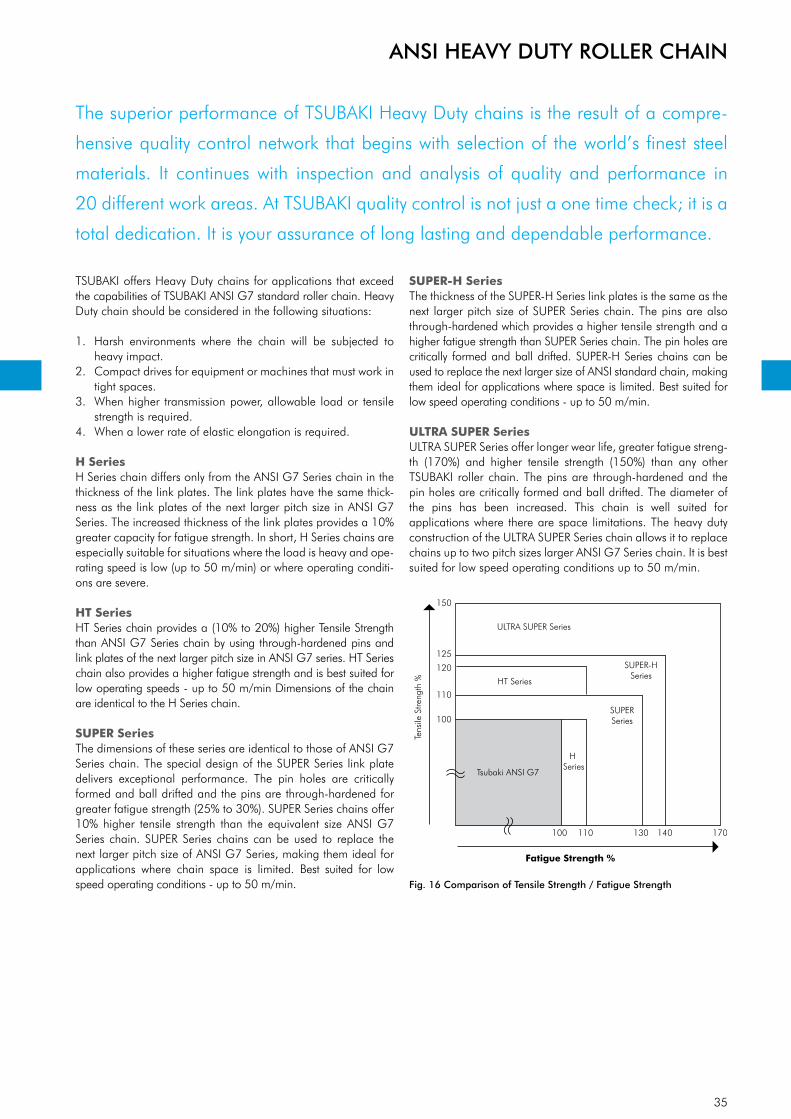
35
ANSI HEAVY DUTY ROLLER CHAIN
The superior performance of TSUBAKI Heavy Duty chains is the result of a compre-
hensive quality control network that begins with selection of the world’s finest steel
materials. It continues with inspection and analysis of quality and performance in
20 different work areas. At TSUBAKI quality control is not just a one time check; it is a
total dedication. It is your assurance of long lasting and dependable performance.
Tsubaki ANSI G7
150
125
120
110
100
100
Shock Load Resistance %
Tens
ile S
treng
th % HT Series
SUPERSeries
SUPER-HSeries
H Series
ULTRA SUPER Series
110 130 140 170
TSUBAKI offers Heavy Duty chains for applications that exceed the capabilities of TSUBAKI ANSI G7 standard roller chain. Heavy Duty chain should be considered in the following situations:
1. Harsh environments where the chain will be subjected to heavy impact.
2. Compact drives for equipment or machines that must work in tight spaces.
3. When higher transmission power, allowable load or tensile strength is required.
4. When a lower rate of elastic elongation is required.
H SeriesH Series chain differs only from the ANSI G7 Series chain in the thickness of the link plates. The link plates have the same thick-ness as the link plates of the next larger pitch size in ANSI G7 Series. The increased thickness of the link plates provides a 10% greater capacity for fatigue strength. In short, H Series chains are especially suitable for situations where the load is heavy and ope-rating speed is low (up to 50 m/min) or where operating conditi-ons are severe.
HT SeriesHT Series chain provides a (10% to 20%) higher Tensile Strength than ANSI G7 Series chain by using through-hardened pins and link plates of the next larger pitch size in ANSI G7 series. HT Series chain also provides a higher fatigue strength and is best suited for low operating speeds - up to 50 m/min Dimensions of the chain are identical to the H Series chain.
SUPER SeriesThe dimensions of these series are identical to those of ANSI G7 Series chain. The special design of the SUPER Series link plate delivers exceptional performance. The pin holes are critically formed and ball drifted and the pins are through-hardened for greater fatigue strength (25% to 30%). SUPER Series chains offer 10% higher tensile strength than the equivalent size ANSI G7 Series chain. SUPER Series chains can be used to replace the next larger pitch size of ANSI G7 Series, making them ideal for applications where chain space is limited. Best suited for low speed operating conditions - up to 50 m/min.
SUPER-H SeriesThe thickness of the SUPER-H Series link plates is the same as the next larger pitch size of SUPER Series chain. The pins are also through-hardened which provides a higher tensile strength and a higher fatigue strength than SUPER Series chain. The pin holes are critically formed and ball drifted. SUPER-H Series chains can be used to replace the next larger size of ANSI standard chain, making them ideal for applications where space is limited. Best suited for low speed operating conditions - up to 50 m/min.
ULTRA SUPER SeriesULTRA SUPER Series offer longer wear life, greater fatigue streng-th (170%) and higher tensile strength (150%) than any other TSUBAKI roller chain. The pins are through-hardened and the pin holes are critically formed and ball drifted. The diameter of the pins has been increased. This chain is well suited for applications where there are space limitations. The heavy duty construction of the ULTRA SUPER Series chain allows it to replace chains up to two pitch sizes larger ANSI G7 Series chain. It is best suited for low speed operating conditions up to 50 m/min.
Fig. 16 Comparison of Tensile Strength / Fatigue Strength
Fatigue Strength %
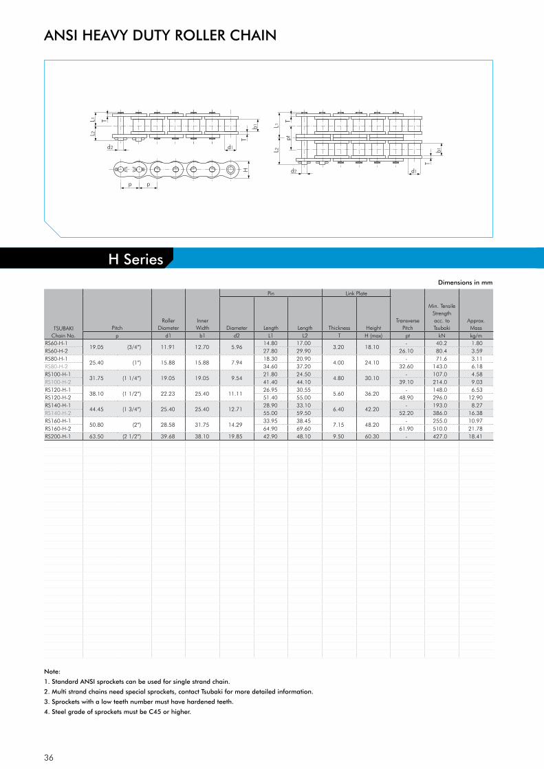
36
L2
L1
d2 d1
p
H
T
T
p
b1
L2
L1
d2 d1
T
T
b1
pt
OL
L
L1
L1
2POL
ANSI HEAVY DUTY ROLLER CHAIN
Dimensions in mm
Note:
1. Standard ANSI sprockets can be used for single strand chain.
2. Multi strand chains need special sprockets, contact Tsubaki for more detailed information.
3. Sprockets with a low teeth number must have hardened teeth.
4. Steel grade of sprockets must be C45 or higher.
H Series
TSUBAKIChain No.
PitchRoller
DiameterInner Width
Pin Link Plate
Transverse Pitch
Min. Tensile Strengthacc. to Tsubaki
Approx. MassDiameter Length Length Thickness Height
p d1 b1 d2 L1 L2 T H (max) pt kN kg/mRS60-H-1
19.05 (3/4”) 11.91 12.70 5.9614.80 17.00
3.20 18.10- 40.2 1.80
RS60-H-2 27.80 29.90 26.10 80.4 3.59RS80-H-1
25.40 (1”) 15.88 15.88 7.9418.30 20.90
4.00 24.10- 71.6 3.11
RS80-H-2 34.60 37.20 32.60 143.0 6.18RS100-H-1
31.75 (1 1/4”) 19.05 19.05 9.5421.80 24.50
4.80 30.10- 107.0 4.58
RS100-H-2 41.40 44.10 39.10 214.0 9.03RS120-H-1
38.10 (1 1/2”) 22.23 25.40 11.1126.95 30.55
5.60 36.20- 148.0 6.53
RS120-H-2 51.40 55.00 48.90 296.0 12.90RS140-H-1
44.45 (1 3/4”) 25.40 25.40 12.7128.90 33.10
6.40 42.20- 193.0 8.27
RS140-H-2 55.00 59.50 52.20 386.0 16.38RS160-H-1
50.80 (2”) 28.58 31.75 14.2933.95 38.45
7.15 48.20- 255.0 10.97
RS160-H-2 64.90 69.60 61.90 510.0 21.78RS200-H-1 63.50 (2 1/2”) 39.68 38.10 19.85 42.90 48.10 9.50 60.30 - 427.0 18.41

37
L2L1
d2 d1
p
HT
T
p
b1
TSUBAKIChain No.
PitchRoller
DiameterInner Width
Pin Link Plate
Min. Tensile Strengthacc. to Tsubaki
Av. Tensile Strengthacc. to Tsubaki
Approx. MassDiameter Length Length Thickness Height
p d1 b1 d2 L1 L2 T H (max) kN kN kg/mRS60-HT-1 19.05 (3/4”) 11.91 12.70 5.96 14.80 17.00 3.20 18.10 48.1 55.9 1.80RS80-HT-1 25.40 (1”) 15.88 15.88 7.94 18.30 20.90 4.00 24.10 81.4 93.2 3.11RS100-HT-1 31.75 (1 1/4”) 19.05 19.05 9.54 21.80 24.50 4.80 30.10 124.0 142.0 4.58RS120-HT-1 38.10 (1 1/2”) 22.23 25.40 11.11 26.95 30.55 5.60 36.20 167.0 191.0 6.53RS140-HT-1 44.45 (1 3/4”) 25.40 25.40 12.71 28.90 33.10 6.40 42.20 218.0 250.0 8.27RS160-HT-1 50.80 (2”) 28.58 31.75 14.29 33.95 38.45 7.15 48.20 278.0 319.0 10.97RS200-HT-1 63.50 (2 1/2”) 39.68 38.10 19.85 42.90 48.10 9.50 60.30 486.0 559.0 18.41RS240-HT-1 76.20 (3”) 47.63 47.63 23.81 54.80 62.30 12.70 72.40 768.0 883.0 29.13
Dimensions in mm
Note:
1. Semi press-fit type connecting links are supplied.
2. Standard ANSI sprockets can be used for single strand chain.
3. Sprockets with a low teeth number must have hardened teeth.
4. Steel grade of sprockets must be C45 or higher.
5. Multi strand chains are available on request.
6. Pins are quad riveted.
7. RS240-HT uses a spring pin for the connecting link.
ANSI HEAVY DUTY ROLLER CHAIN
HT Series
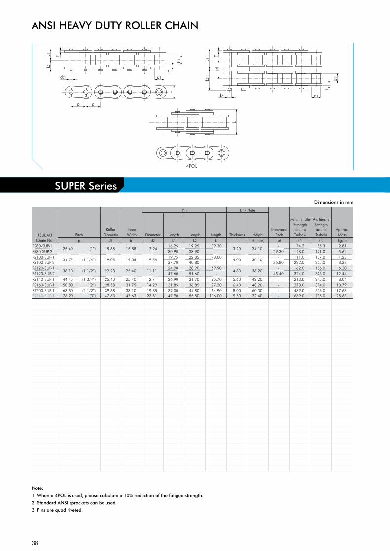
38
L2
L1
d2 d1
p
H
T
T
p
b1
L2
d2 d1
T
b1
L1 T
pt
4POL
LTSUBAKI
Chain No.Pitch
Roller Diameter
Inner Width
Pin Link Plate
Transverse Pitch
Min. Tensile Strengthacc. to Tsubaki
Av. Tensile Strengthacc. to Tsubaki
Approx. MassDiameter Length Length Length Thickness Height
p d1 b1 d2 L1 L2 L T H (max) pt kN kN kg/mRS80-SUP-1
25.40 (1”) 15.88 15.88 7.9416.25 19.25 39.30
3.20 24.10- 74.2 85.3 2.81
RS80-SUP-2 30.90 33.90 - 29.30 148.0 171.0 5.62RS100-SUP-1
31.75 (1 1/4”) 19.05 19.05 9.5419.75 22.85 48.00
4.00 30.10- 111.0 127.0 4.25
RS100-SUP-2 37.70 40.80 - 35.80 222.0 255.0 8.38RS120-SUP-1
38.10 (1 1/2”) 22.23 25.40 11.1124.90 28.90 59.90
4.80 36.20- 162.0 186.0 6.30
RS120-SUP-2 47.60 51.60 - 45.40 324.0 373.0 12.44RS140-SUP-1 44.45 (1 3/4”) 25.40 25.40 12.71 26.90 31.70 65.70 5.60 42.20 - 213.0 245.0 8.04RS160-SUP-1 50.80 (2”) 28.58 31.75 14.29 31.85 36.85 77.20 6.40 48.20 - 273.0 314.0 10.79RS200-SUP-1 63.50 (2 1/2”) 39.68 38.10 19.85 39.00 44.80 94.90 8.00 60.30 - 439.0 505.0 17.63RS240-SUP-1 76.20 (3”) 47.63 47.63 23.81 47.90 55.50 116.00 9.50 72.40 - 639.0 735.0 25.63
Dimensions in mm
Note:
1. When a 4POL is used, please calculate a 10% reduction of the fatigue strength.
2. Standard ANSI sprockets can be used.
3. Pins are quad riveted.
ANSI HEAVY DUTY ROLLER CHAIN
SUPER Series
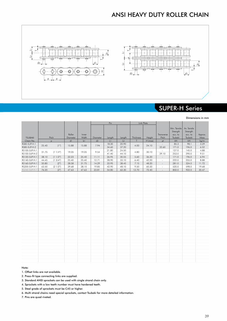
39
L2
L1
d2 d1
p
H
T
T
p
b1
L2
d2 d1
T
b1
L1 T
pt
4POL
LTSUBAKI
Chain No.Pitch
Roller Diameter
Inner Width
Pin Link Plate
Transverse Pitch
Min. Tensile Strengthacc. to Tsubaki
Av. Tensile Strengthacc. to Tsubaki
Approx. MassDiameter Length Length Thickness Height
p d1 b1 d2 L1 L2 T H (max) pt kN kN kg/mRS80-SUP-H-1
25.40 (1”) 15.88 15.88 7.9418.30 20.90
4.00 24.10- 85.3 98.1 3.29
RS80-SUP-H-2 34.60 37.20 32.60 171.0 196.0 6.52RS100-SUP-H-1
31.75 (1 1/4”) 19.05 19.05 9.5421.80 24.50
4.80 30.10- 127.0 145.0 4.88
RS100-SUP-H-2 41.40 44.10 39.10 253.0 290.0 9.51RS120-SUP-H-1 38.10 (1 1/2”) 22.23 25.40 11.11 26.95 30.55 5.60 36.20 - 171.0 196.0 6.94RS140-SUP-H-1 44.45 (1 3/4”) 25.40 25.40 12.71 28.90 33.10 6.40 42.20 - 222.0 255.0 8.88RS160-SUP-H-1 50.80 (2”) 28.58 31.75 14.29 33.95 38.45 7.15 48.20 - 281.0 324.0 11.72RS200-SUP-H-1 63.50 (2 1/2”) 39.68 38.10 19.85 42.90 48.10 9.50 60.30 - 520.0 598.0 19.68RS240-SUP-H-1 76.20 (3”) 47.63 47.63 23.81 54.80 62.30 12.70 72.40 - 802.0 922.0 30.47
Dimensions in mm
Note:
1. Offset links are not available.
2. Press-fit type connecting links are supplied.
3. Standard ANSI sprockets can be used with single strand chain only.
4. Sprockets with a low teeth number must have hardened teeth.
5. Steel grade of sprockets must be C45 or higher.
6. Multi strand chains need special sprockets, contact Tsubaki for more detailed information.
7. Pins are quad riveted.
ANSI HEAVY DUTY ROLLER CHAIN
SUPER-H Series

40
L2L1
d2 d1
p
HT
T
p
b1
Dimensions in mm
TSUBAKIChain No.
PitchRoller
DiameterInner Width
Pin Link Plate
Min. Tensile Strengthacc. to Tsubaki
Av. Tensile Strengthacc. to Tsubaki
Approx. MassDiameter Length Length Thickness Height
p d1 b1 d2 L1 L2 T H (max) kN kN kg/mRF100-US-1 31.75 (1 1/4”) 19.05 19.05 10.32 22.35 25.35 4.80 30.10 149.0 172.0 5.07RF120-US-1 38.10 (1 1/2”) 22.23 25.40 12.28 27.55 31.55 5.60 36.20 213.0 245.0 7.22RF140-US-1 44.45 (1 3/4”) 25.40 25.40 13.97 29.50 34.20 6.40 42.20 273.0 314.0 9.24RF160-US-1 50.80 (2”) 28.58 31.75 15.62 34.50 40.20 7.15 48.20 341.0 392.0 12.19
ULTRA SUPER Series
ANSI HEAVY DUTY ROLLER CHAIN
Note:
1. Standard ANSI sprockets can be used if the sprocket teeth have been hardened.
2. Steel grade of sprockets must be C45 or higher.
3. Offset links are not available.
4. Multi-strand chains are not available.
5. Press-fit type connecting links are supplied.
6. Pins are quad riveted.

41
Roller
Spring Roller (Cushioning)
Sprocket
Sprocket
Standard Roller Chain
Low Noise Drive Chain
Noise
Noise reduction
Technical Evolution TSUBAKI’s uniquely structured spring rollers are used for chain rollers. When TSUBAKI’s Low Noise roller chain engages the sprocket, the spring roller deforms and absorbs the force of impact, reducing impact noise between chain and sprocket.Compared with TSUBAKI’s standard roller chain, noise levels of Low Noise Roller Chain are 6 - 8 dB lower. Working temperature range: -10°C to +60°C. Allowable chain speed: 200 m/min. Advantages Noise ReductionLower noise levels increase comfort levels in the workplace. Besides, lower noise levels also eliminate the need for costly, soundproof enclosures. Stronger than BeltsIn some applications, belts are considered as a countermeasure to noise. However, there are many limitations in terms of strength when considering belts. The TSUBAKI Low Noise roller chain is perfect for applications where the strength of a roller chain is needed without the accompanying noise.
ANSI LOW NOISE ROLLER CHAIN
Inter-Changeability Chains:TSUBAKI Low Noise roller chain is directly interchangeable with ANSI standard roller chain. Sprockets:Standard ANSI roller chain sprockets can be used. However, if the chain cannot be sufficiently lubricated, TSUBAKI recommends installing sprockets with hardened teeth.
Fig. 17 Cushioning Effect
Low Noise Drive Chain - a TSUBAKI innovation - creates a worker-friendly, environ-
mentally friendly plant. It reduces equipment noise, and it eliminates the need for
expensive, hard-to-work-around soundproof enclosures.
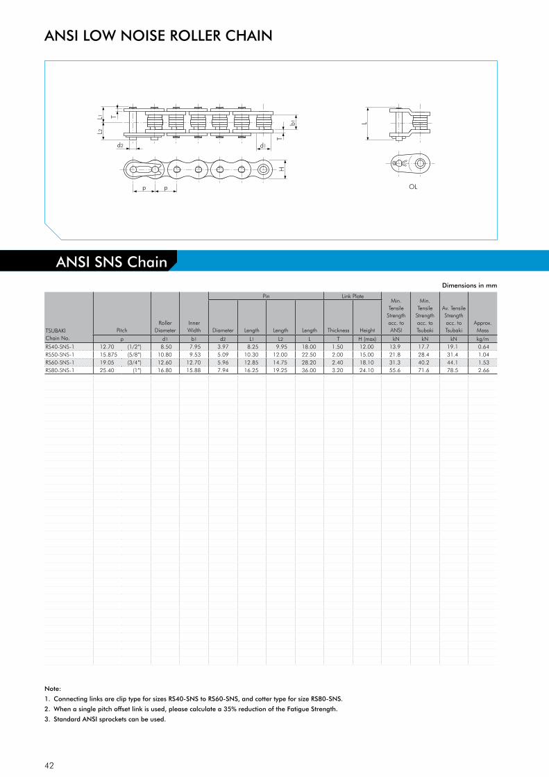
42
L2L1
d2 d1
p
HT
T
p OL
b1 L
TSUBAKIChain No.
PitchRoller
Dia meterInner Width
Pin Link PlateMin.
Tensile Strength acc. to ANSI
Min. Tensile
Strength acc. to Tsubaki
Av. Tensile Strength acc. to Tsubaki
Approx. MassDia meter Length Length Length Thickness Height
p d1 b1 d2 L1 L2 L T H (max) kN kN kN kg/mRS40-SNS-1 12.70 (1/2”) 8.50 7.95 3.97 8.25 9.95 18.00 1.50 12.00 13.9 17.7 19.1 0.64RS50-SNS-1 15.875 (5/8”) 10.80 9.53 5.09 10.30 12.00 22.50 2.00 15.00 21.8 28.4 31.4 1.04RS60-SNS-1 19.05 (3/4”) 12.60 12.70 5.96 12.85 14.75 28.20 2.40 18.10 31.3 40.2 44.1 1.53RS80-SNS-1 25.40 (1”) 16.80 15.88 7.94 16.25 19.25 36.00 3.20 24.10 55.6 71.6 78.5 2.66
Dimensions in mm
Note:
1. Connecting links are clip type for sizes RS40-SNS to RS60-SNS, and cotter type for size RS80-SNS.
2. When a single pitch offset link is used, please calculate a 35% reduction of the Fatigue Strength.
3. Standard ANSI sprockets can be used.
ANSI LOW NOISE ROLLER CHAIN
ANSI SNS Chain
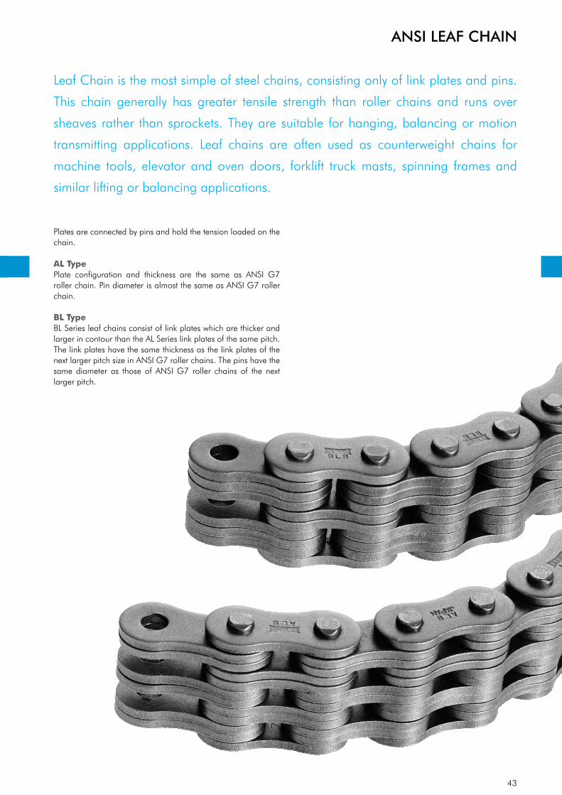
43
Plates are connected by pins and hold the tension loaded on the chain.
AL TypePlate configuration and thickness are the same as ANSI G7 roller chain. Pin diameter is almost the same as ANSI G7 roller chain. BL TypeBL Series leaf chains consist of link plates which are thicker and larger in contour than the AL Series link plates of the same pitch. The link plates have the same thickness as the link plates of the next larger pitch size in ANSI G7 roller chains. The pins have the same diameter as those of ANSI G7 roller chains of the next larger pitch.
ANSI LEAF CHAIN
Leaf Chain is the most simple of steel chains, consisting only of link plates and pins.
This chain generally has greater tensile strength than roller chains and runs over
sheaves rather than sprockets. They are suitable for hanging, balancing or motion
transmitting applications. Leaf chains are often used as counterweight chains for
machine tools, elevator and oven doors, forklift truck masts, spinning frames and
similar lifting or balancing applications.

44
2x2
6x6
Lacing Combination
4x4L2L1
d2
p
HT
T
p d4
TSUBAKIChain No.
PitchLacing
Combination
Pin Link Plate
Min. Tensile Strength
acc. to TsubakiApprox. MassDiameter Length Length Thickness Height
Hole Diameter
p LC d2 L1 L2 T H (max) d4 kN kg/mAL 422
12.70 (1/2”)2 x 2
3.964.20 5.30
1.50 10.40 4.0216.7 0.38
AL 444 4 x 4 7.43 8.52 33.3 0.74AL 466 6 x 6 10.65 11.75 50.5 1.10AL 522
15.875 (5/8”)2 x 2
5.085.43 6.97
2.00 13.00 5.1327.5 0.62
AL 544 4 x 4 9.68 11.22 54.9 1.22AL 566 6 x 6 13.90 15.45 82.4 1.81AL 622
19.05 (3/4”)2 x 2
5.946.33 8.22
2.40 15.60 6.0038.2 0.87
AL 644 4 x 4 11.28 13.17 76.5 1.71AL 666 6 x 6 16.23 18.12 115.0 2.54AL 822
25.40 (1”)2 x 2
7.908.18 10.97
3.20 20.80 7.9764.7 1.51
AL 844 4 x 4 14.90 17.70 129.0 2.98AL 866 6 x 6 21.60 24.40 194.0 4.44AL 1022
31.75 (1 1/4”)2 x 2
9.4810.03 13.22
4.00 26.00 9.5798.1 2.69
AL 1044 4 x 4 18.35 21.55 196.0 5.31AL 1066 6 x 6 26.65 29.85 294.0 7.93AL 1222
38.10 (1 1/2”)2 x 2
11.0412.10 15.80
4.80 31.20 11.14141.0 3.57
AL 1244 4 x 4 22.00 25.70 282.0 7.07AL 1266 6 x 6 31.93 35.62 424.0 10.56AL 1444
44.45 (1 3/4”)4 x 4
12.6425.65 30.15
5.60 36.40 12.74373.0 10.34
AL 1466 6 x 6 37.28 41.77 559.0 15.16AL 1644
50.80 (2”)4 x 4
14.2129.03 34.02
6.40 41.60 14.32471.0 12.98
AL 1666 6 x 6 42.23 47.22 706.0 19.41
Dimensions in mm
Note:
1. For more detailed information regarding clevises and sheaves, please contact Tsubaki.
ANSI LEAF CHAIN
AL Type
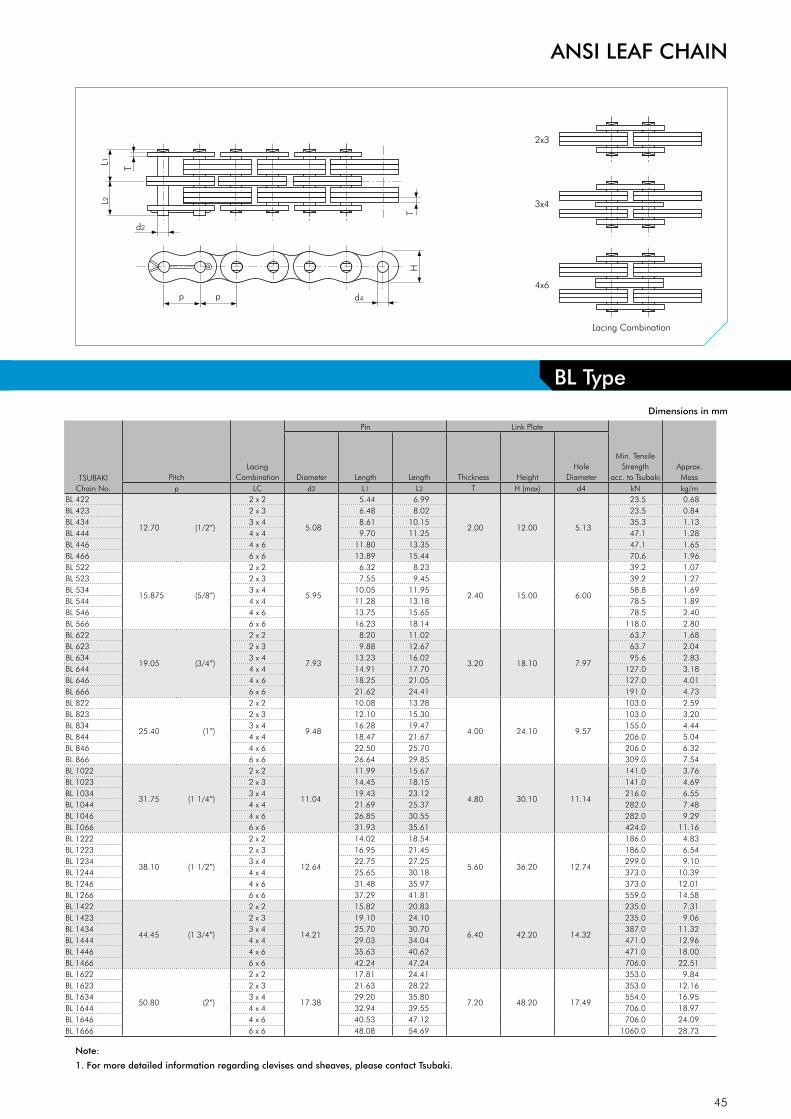
45
2x3
4x6
Lacing Combination
3x4L2L1
d2
p
HT
T
p d4
Dimensions in mm
Note:
1. For more detailed information regarding clevises and sheaves, please contact Tsubaki.
ANSI LEAF CHAIN
BL Type
TSUBAKIChain No.
PitchLacing
Combination
Pin Link Plate
Min. Tensile Strength
acc. to TsubakiApprox. MassDiameter Length Length Thickness Height
Hole Diameter
p LC d2 L1 L2 T H (max) d4 kN kg/mBL 422
12.70 (1/2”)
2 x 2
5.08
5.44 6.99
2.00 12.00 5.13
23.5 0.68BL 423 2 x 3 6.48 8.02 23.5 0.84BL 434 3 x 4 8.61 10.15 35.3 1.13BL 444 4 x 4 9.70 11.25 47.1 1.28BL 446 4 x 6 11.80 13.35 47.1 1.65BL 466 6 x 6 13.89 15.44 70.6 1.96BL 522
15.875 (5/8”)
2 x 2
5.95
6.32 8.23
2.40 15.00 6.00
39.2 1.07BL 523 2 x 3 7.55 9.45 39.2 1.27BL 534 3 x 4 10.05 11.95 58.8 1.69BL 544 4 x 4 11.28 13.18 78.5 1.89BL 546 4 x 6 13.75 15.65 78.5 2.40BL 566 6 x 6 16.23 18.14 118.0 2.80BL 622
19.05 (3/4”)
2 x 2
7.93
8.20 11.02
3.20 18.10 7.97
63.7 1.68BL 623 2 x 3 9.88 12.67 63.7 2.04BL 634 3 x 4 13.23 16.02 95.6 2.83BL 644 4 x 4 14.91 17.70 127.0 3.18BL 646 4 x 6 18.25 21.05 127.0 4.01BL 666 6 x 6 21.62 24.41 191.0 4.73BL 822
25.40 (1”)
2 x 2
9.48
10.08 13.28
4.00 24.10 9.57
103.0 2.59BL 823 2 x 3 12.10 15.30 103.0 3.20BL 834 3 x 4 16.28 19.47 155.0 4.44BL 844 4 x 4 18.47 21.67 206.0 5.04BL 846 4 x 6 22.50 25.70 206.0 6.32BL 866 6 x 6 26.64 29.85 309.0 7.54BL 1022
31.75 (1 1/4”)
2 x 2
11.04
11.99 15.67
4.80 30.10 11.14
141.0 3.76BL 1023 2 x 3 14.45 18.15 141.0 4.69BL 1034 3 x 4 19.43 23.12 216.0 6.55BL 1044 4 x 4 21.69 25.37 282.0 7.48BL 1046 4 x 6 26.85 30.55 282.0 9.29BL 1066 6 x 6 31.93 35.61 424.0 11.16BL 1222
38.10 (1 1/2”)
2 x 2
12.64
14.02 18.54
5.60 36.20 12.74
186.0 4.83BL 1223 2 x 3 16.95 21.45 186.0 6.54BL 1234 3 x 4 22.75 27.25 299.0 9.10BL 1244 4 x 4 25.65 30.18 373.0 10.39BL 1246 4 x 6 31.48 35.97 373.0 12.01BL 1266 6 x 6 37.29 41.81 559.0 14.58BL 1422
44.45 (1 3/4”)
2 x 2
14.21
15.82 20.83
6.40 42.20 14.32
235.0 7.31BL 1423 2 x 3 19.10 24.10 235.0 9.06BL 1434 3 x 4 25.70 30.70 387.0 11.32BL 1444 4 x 4 29.03 34.04 471.0 12.96BL 1446 4 x 6 35.63 40.62 471.0 18.00BL 1466 6 x 6 42.24 47.24 706.0 22.51BL 1622
50.80 (2”)
2 x 2
17.38
17.81 24.41
7.20 48.20 17.49
353.0 9.84BL 1623 2 x 3 21.63 28.22 353.0 12.16BL 1634 3 x 4 29.20 35.80 554.0 16.95BL 1644 4 x 4 32.94 39.55 706.0 18.97BL 1646 4 x 6 40.53 47.12 706.0 24.09BL 1666 6 x 6 48.08 54.69 1060.0 28.73
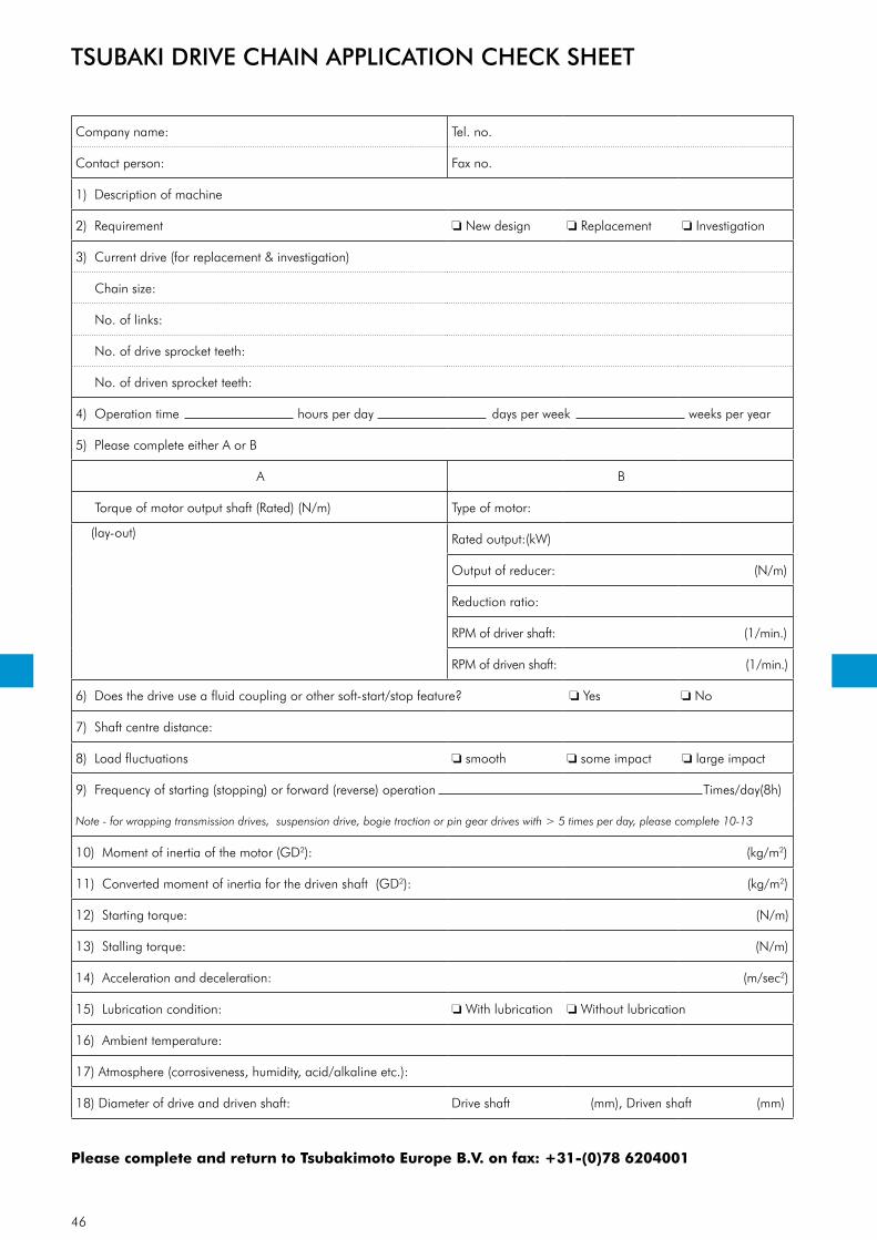
46
TSUBAKI DRIVE CHAIN APPLICATION CHECK SHEET
Company name: Tel. no.
Contact person: Fax no.
1) Description of machine
2) Requirement o New design o Replacement o Investigation
3) Current drive (for replacement & investigation)
Chain size:
No. of links:
No. of drive sprocket teeth:
No. of driven sprocket teeth:
4) Operation time hours per day days per week weeks per year
5) Please complete either A or B
A B
Torque of motor output shaft (Rated) (N/m) Type of motor:
(lay-out) Rated output:(kW)
Output of reducer: (N/m)
Reduction ratio:
RPM of driver shaft: (1/min.)
RPM of driven shaft: (1/min.)
6) Does the drive use a fluid coupling or other soft-start/stop feature? o Yes o No
7) Shaft centre distance:
8) Load fluctuations o smooth o some impact o large impact
9) Frequency of starting (stopping) or forward (reverse) operation Times/day(8h)
Note - for wrapping transmission drives, suspension drive, bogie traction or pin gear drives with > 5 times per day, please complete 10-13
10) Moment of inertia of the motor (GD2): (kg/m2)
11) Converted moment of inertia for the driven shaft (GD2): (kg/m2)
12) Starting torque: (N/m)
13) Stalling torque: (N/m)
14) Acceleration and deceleration: (m/sec2)
15) Lubrication condition: o With lubrication o Without lubrication
16) Ambient temperature:
17) Atmosphere (corrosiveness, humidity, acid/alkaline etc.):
18) Diameter of drive and driven shaft: Drive shaft (mm), Driven shaft (mm)
Please complete and return to Tsubakimoto Europe B.V. on fax: +31-(0)78 6204001
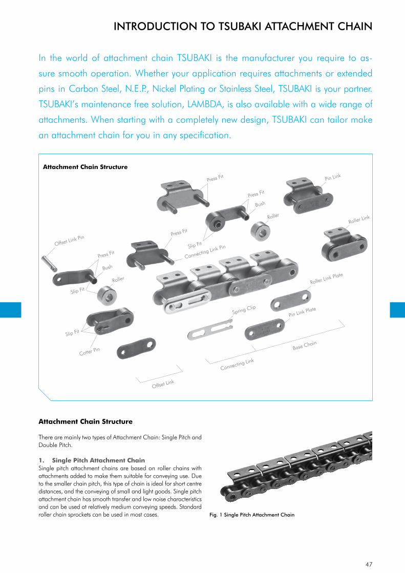
47
Offset Link Pin
Press Fit
Bush
Connecting Link Pin
Slip Fit
Cotter Pin
Roller
Roller
Spring Clip
Roller Link Plate
Pin Link
Roller Link
Offset Link
Connecting Link
Base Chain
Pin Link Plate
Press Fit
Press Fit
BushPress Fit
Slip Fit
Slip Fit
INTRODUCTION TO TSUBAKI ATTACHMENT CHAIN
Attachment Chain Structure
There are mainly two types of Attachment Chain: Single Pitch and Double Pitch.
1. Single Pitch Attachment ChainSingle pitch attachment chains are based on roller chains with attachments added to make them suitable for conveying use. Due to the smaller chain pitch, this type of chain is ideal for short centre distances, and the conveying of small and light goods. Single pitch attachment chain has smooth transfer and low noise characte ristics and can be used at relatively medium conveying speeds. Standard roller chain sprockets can be used in most cases. Fig. 1 Single Pitch Attachment Chain
In the world of attachment chain TSUBAKI is the manufacturer you require to as-
sure smooth operation. Whether your application requires attachments or extended
pins in Carbon Steel, N.E.P., Nickel Plating or Stainless Steel, TSUBAKI is your partner.
TSUBAKI’s maintenance free solution, LAMBDA, is also available with a wide range of
attachments. When starting with a completely new design, TSUBAKI can tailor make
an attachment chain for you in any specification.
Attachment Chain Structure

48
INTRODUCTION TO TSUBAKI ATTACHMENT CHAIN
2. Double Pitch Attachment ChainThis is the most commonly used attachment chain and is utilised widely in the automotive parts, electric, electronic, and precision machinery industries. Double pitch roller chain has the same basic construction as single pitch roller chain, but has twice the pitch length. A major benefit is that whilst larger conveyor lengths are possible, a double pitch chain uses only half the components of a single pitch chain in the same application, resulting in less components to wear.
The choice of sprockets depends on the roller type applied to the chain. Chain with S-type rollers can be driven by standard roller chain sprockets (> 30 teeth). The chain engages every second tooth. Special sprockets are needed when R-type rollers are used.
Fig. 2 Double Pitch Attachment Chain
3. Three Basic DimensionsPitch, Roller Diameter and Inner Width are known as the “Three Basic Dimensions of Roller Chain.” When these three dimensions are identical to the existing chain being replaced, then the roller chain and sprockets are dimensionally compatible. With attach-ment chain a lot of additional dimensions are important to ensure a safe replacement and carefree installation of the chain. Please refer to our dimension tables for the appropriate dimensions.
4. Basic Parts
Link PlateThe link plate is the component that bears the tension placed on the chain. Usually this is a repeated load, sometimes accom-panied by shock. Therefore, the plate must not only have great static tensile strength, it must also hold up to the dynamic forces of load and shock.
PinThe pin is subject to shearing and bending forces transmitted by the plate. At the same time, it forms a load-bearing part (together with the bush) when the chain flexes during sprocket engage-ment. Therefore, the pin needs high tensile and shear strength, resistance to bending, and must also have sufficient endurance against shock and wear.
BushThe bush is subject to complex forces from all parts, especially from the repetition of shock loads when the chain engages with the sprocket. Therefore, the bush needs extremely high shock resistance. In addition, the bush forms a load-bearing part together with the pin and as such requires great wear resistance.
RollerThe roller is subject to impact load as it mates with the sprocket tooth during engagement of the chain with the sprocket. After engagement, the roller changes its point of contact and balance. It is held between the sprocket tooth and bush, and moves on the tooth face whilst receiving a compression load. Therefore, it must be resistant to wear and still have strength against shock, fatigue and compression.
There are two types of rollers for Double Pitch Attachment chain: S-roller (standard) and R-roller (oversized). The S-rollers are used in short-length and slow-speed conveying. The R-rollers are most commonly used for longer conveying applications.(RS35 is a bush chain and does not have rollers).
Roller LinkTwo bushes are press fit into two roller link plates and rollers are inserted to allow rotation around the outside of the bushes during operation. This is the same for single and for multi strand chains.
Pin LinkThe pin link consists of two pins that have been press fit into two pin link plates.
Spring Clip and Cotter PinThe spring clip prevent the link plate from becoming detached, with the cotter pin type being as an added security measure where there is as possibly of the clip being removed due to interference from chain guides or some other aspect of the application.
5. Assembly PartsRoller chains are usually made up of a number of inner and outer links in an endless formation. Although offset links can be used when there is an odd number of links in the roller chain, it is better to use a design that requires an even number of links, thus eliminating the use of offset links.
Connecting LinksThere are two types of connecting link: spring clip connecting link and cotter pin connecting link. It’s common to use slip fit spring clip connecting links for small size attachment chains. Cotter pin connecting links are used for large size attachment chains and on customer request.

49
A-1 SKK-1SAA-1KK-1AA-1SK-1SA-1K-1
WA-0 WK-0WA-2WA-1 WK-2WK-1
WSA-0 WSA-2WSA-1 WSK-0 WSK-2WSK-1
D-3D-1
EP
A-1 SKK-1SAA-1KK-1AA-1SK-1SA-1K-1
WA-0 WK-0WA-2WA-1 WK-2WK-1
WSA-0 WSA-2WSA-1 WSK-0 WSK-2WSK-1
D-3D-1
A-1 SKK-1 SAA-1 KK-1 AA-1 SK-1 SA-1 K-1
WA-0 WK-0 WA-2 WA-1 WK-2 WK-1
WSA-0 WSA-2 WSA-1 WSK-0 WSK-2 WSK-1
Extended Pin
EW
INTRODUCTION TO TSUBAKI ATTACHMENT CHAIN
Fig. 3 Overview Single Pitch Attachment Types
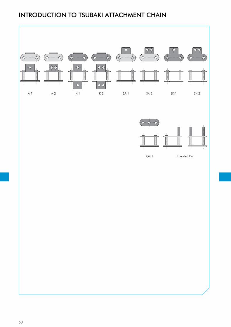
50
A-1 A-2 K-1 K-2 SA-1 SA-2 SK-1 SK-2
GK-1 D-1 D-3Extended Pin
INTRODUCTION TO TSUBAKI ATTACHMENT CHAIN
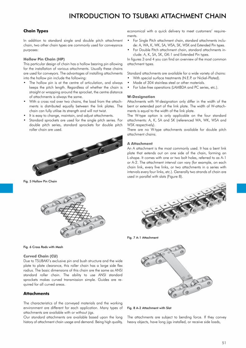
51
Chain Types
In addition to standard single and double pitch attachment chain, two other chain types are commonly used for conveyance purposes:
Hollow Pin Chain (HP)This particular design of chain has a hollow bearing pin allowing for the installation of various attachments. Usually these chains are used for conveyors. The advantages of installing attachments into the hollow pin include the following:• The hollow pin is at the centre of articulation, and always
keeps the pitch length. Regardless of whether the chain is straight or wrapping around the sprocket, the centre distance of attachments is always the same.
• With a cross rod over two chains, the load from the attach-ments is distributed equally between the link plates. The chain can fully utilise its strength and will not twist.
• It is easy to change, maintain, and adjust attachments.• Standard sprockets are used for the single pitch series. For
double pitch series, standard sprockets for double pitch roller chain are used.
Fig. 5 Hollow Pin Chain
Fig. 6 Cross Rods with Mesh
Curved Chain (CU)Due to TSUBAKI’s exclusive pin and bush structure and the wide plate to plate clearance, this roller chain has a large side flex radius. The basic dimensions of this chain are the same as ANSI standard roller chain. The ability to use ANSI standard sprockets makes curved transmission simple. Guides are re-quired for all curved areas.
Attachments
The characteristics of the conveyed materials and the working environment are different for each application. Many types of attachments are available with or without jigs.Our standard attachments are available based upon the long history of attachment chain usage and demand. Being high quality,
economical with a quick delivery to meet customers’ require-ments.• For Single Pitch attachment chain, standard attachments inclu-
de: A, WA, K, WK, SA, WSA, SK, WSK and Extended Pin types.• For Double Pitch attachment chain, standard attachments in-
clude: A, K, SA, SK, GK-1 and Extended Pin types.In figures 3 and 4 you can find an overview of the most common attachment types.
Standard attachments are available for a wide variety of chains: • With special surface treatments (N.E.P. or Nickel-Plated).• Made of 304 stainless steel or other materials.• For lube-free operations (LAMBDA and PC series, etc.).
W-DesignationAttachments with W-designation only differ in the width of the bent or extended part of the link plate. The width of W-attach-ments is equal to the width of the link plate.The W-type option is only applicable on the four standard attachments: A, K, SA and SK (referenced WA, WK, WSA and WSK respectively).There are no W-type attachments available for double pitch attachment chains.
A AttachmentAn A attachment is the most commonly used. It has a bent link plate that extends out on one side of the chain, forming an L-shape. It comes with one or two bolt holes, referred to as A-1 or A-2. The attachment interval can vary (for example, on each chain link, every five links, or two attachments in a series with intervals every four links, etc.). Generally two strands of chain are used in parallel with slats (Figure 8).
Fig. 7 A-1 Attachment
Fig. 8 A-2 Attachment with Slat
The attachments are subject to bending force. If they convey heavy objects, have long jigs installed, or receive side loads,
INTRODUCTION TO TSUBAKI ATTACHMENT CHAIN

52
twisting force is added to the bending force. Depending on the application, please ensure you consider these forces in your cal-culations.The shape of the attachment influences the design of the equip-ment. If slats do not cover the chain rollers, guide rails may be used to support the chain rollers on the return side.
K AttachmentThis is an attachment made by installing A attachments on both sides of the chain. The attachment is called K-1 or K-2 based on the number of bolt holes on each individual attachment. The attach-ment interval can vary, same as the A attachment (Figure 9).
Fig. 9 K-1 Attachment
The top of the attachment is higher than the R-rollers, so slats or jigs can be installed over the chains (Figure 10). Objects can also be conveyed directly on the K attachments.When a wide slat is installed on two A attachment chains, the slats may not be able to support the weight. A chain with K attachments is installed between the A attachment chains to help support the load.
When the slats are rigid enough and are fastened well to the attachments, there is almost no effect from bending force to the strength of the attachment. But if the slat is not fastened well, make sure to consider the bending force in your calculation.
If long jigs are installed, or the attachment receives side loads, it will be exposed to twisting forces.The return side of the K attachment chain cannot be supported with guide rails on the rollers. The return may be slack or sup-ported in some other way.
Fig. 10 K Attachment with L-angle
SA AttachmentFor the SA attachment, the link plate is extended on one side of the chain, and one or two bolt holes are installed. These are called SA-1 or SA-2 depending on the number of the bolt holes (Figure 11). The attachment interval can vary the same as the A attachment. These attachments may be adapted for use with hooks or slats (Figure 12).The SA attachment is simpler and stronger than the A attach-ment, and may receive bending and twisting force depending on the direction of the loads.
The return side of the chains can be supported by guide rails on the rollers unless bolts extend into the attachment.
Fig. 11 SA-1 Attachment
Fig. 12 SA-2 Attachments with Hook
SK AttachmentSK attachments are made by installing SA attachments on both sides of the chain. They are called SK-1 or SK-2, depending on the number of bolt holes on each individual attachment. The attach-ment interval can vary the same as the A attachment (Figure 13).
Usually SK attachments are used with dogs or jigs (Figure 14). SK attachments are strong enough to withstand bending or twisting forces.The return side of SK attachment chains cannot be supported by guide rails on the rollers as can A or SA attachment chains. The return must be slack or supported in some other manner.
Fig. 13 SK-1 Attachments
Fig. 14 SK-2 Attachments with V-block
INTRODUCTION TO TSUBAKI ATTACHMENT CHAIN

53
Extended Pin AttachmentIn this form, one end of the pin is extended. The attachment interval can vary the same as the A attachment (Figure 15).As shown in Figure 16, two sets of D attachment chains can be connected to cross rods, or jigs (such as blocks).The extended pins are subjected to bending and shearing forces. The return side of the D attachment chain can be supported by guide rails on the rollers.
Fig. 15 Extended Pin Attachment
Fig. 16 D Attachments with Jigs
GK-1 AttachmentA hole is added to the centre of both link plates, to be able to attach cross rods between two (or more) parallel running chains. The attachment interval can vary the same as the A attachment (Figure 17). This type of attachment is often used when cross rods with larger diameters than the maximum applicable diameters of hollow pin chains are used. This type of attachment is only available as a double pitch attachment chain, Type R-rollers can not be used in combination with GK-1 attachments due to the interference between the roller and the hole in the link plates.
Fig. 17 GK-1 Attachment
Chain Length Tolerance
Maintaining an accurate overall length tolerance in attachment chain is essential for conveying and index drive equipment used in such applications as inserting components, product assembly lines, integrated circuit boards and board/paper & packaging amongst many others.The tolerance of the overall chain length is depending on the chain type and the appropriate international standard:
INTRODUCTION TO TSUBAKI ATTACHMENT CHAIN
Single Pitch Chain• BS Single Pitch Roller Chain According to ISO 606: 0% to +0.15%• BS Single Pitch Attachment Chain According to ISO 606: 0% to +0.30%• ANSI Single Pitch Roller Chain According to ANSI: 0% to +0.15%• ANSI Single Pitch Attachment Chain According to ANSI: 0% to +0.30%
Double Pitch Chain• ANSI Double Pitch Roller Chain According to ANSI: 0% to +0.13%• ANSI Double Pitch Attachment Chain According to ANSI: 0% to +0.25%
TSUBAKI chain length tolerances are very narrow by nature, ho-wever some markets require narrow tolerance chain; in the market often referred to, and marketed as 1/3 DIN or 1/6 DIN length tolerance chain. TSUBAKI chain coming from the same production lot is generally complying with these tolerances as a standard; once again our constant high quality.Figure 18 shows the amount of variation for several types of chain chosen at random from the same production run.
Chain Length [mm] Matched Tolerance [mm]< 14 m < 3 mm
14~30 m < 4 mm30~44 m < 5 mm
Fig. 18 Attachment Chains Chosen at Random from Same
Production Lot
When even more accurate tolerances are required, TSUBAKI can offer an effective solution with the Match & Tag Service. This can be useful for attachment chains which have to run parallel in pairs and where a minimum of chain length tolerance is required.
Match & Tag Service: High Accuracy, Narrow Tolerance Service
For TSUBAKI quality is second nature- and so for customers with specific application requirements, we are able to supply chains with a specific length tolerance, or even pairs & multiple chains length matched and tagged in the same way for easy identifi-cation and installation. This is as a result of the sophisticated chain length measurement equipment (the “Matchy”) kept in house within the European headquarters with supply times for such chains kept to a minimum-ideal for distributors, final consu-mers and OEM customers alike.
SizesThe Matchy at our European Headquarters is equipped for:• BS Single Pitch sizes RS08B to RS32B• ANSI Single Pitch sizes RS40 to RS100 (including Heavy Duty
Series)• ANSI Double Pitch sizes RF2040 to RF2100For other sizes and specific demands please contact TSUBAKI, our Engineering Department will explain all options available.
TolerancesWhen chains have to run in parallel for conveying purposes in for instance packaging machines or when a minimum of difference

54
1A 2A2B1B
Fig. 20 Matching Chain Strands
Fig. 21 Local Assembly Service
INTRODUCTION TO TSUBAKI ATTACHMENT CHAIN
in chain length is required in lifting applications (accumulator towers in the steel and carpet industry) TSUBAKI excels in quality performance. We can guarantee a maximum chain length diffe-rence of 0.50 mm independent of the total chain length demanded by our customers!
Fig. 19 Tagging of Matched Chain Strands
Local Assembly Service
TSUBAKI offers a huge range of attachment chains to suit virtu-ally any application.
An extended range of stock components covering the majority of standard applications, and a Built To Order service using more specialised attachments also held in stock within Tsubakimoto Europe-swift deliveries can be both achieved...and maintained. Along with the Made To Order service when very unusual or high-ly specialist solutions can be delivered on accurate lead times from TSUBAKI’s dedicated state of the art factory results in a comprehensive supply chain capability.
As our customers increase production capacity and reduce main-tenance windows, we believe that this high level of product avai-lability and swift delivery can make a difference. This policy re-presents TSUBAKI’s core values.
If a standard attachment chain is required (for volumes typically under 50 meters) it can be assembled from stock lengths and/or components. If an attachment is required with a specific dimen-sion requirement such as a non standard assembly hole then the attachment can be produced within Europe.

55
Special Coated PinSpecial Oil ImpregnatedSintered Bush
Ring Coin
Roller
BS LAMBDA LUBE FREE ATTACHMENT CHAIN
TSUBAKI’s LAMBDA chains were the first in the industry to use a special oil-impregnated
bush. Since their launch in 1988, they have been adopted for diverse industries and
applications, and their performance has been highly rated. TSUBAKI has a wide line-
up of lube-free, long life products that help customers reduce costs.
Technical EvolutionAs a pioneer in the lube-free chain market, TSUBAKI will reveal some of the key elements behind BS LAMBDA’s outstanding performance:
Sintered BushA special oil-impregnated sintered bush in combination with a special coated pin for long-term internal lubrication is the secret of TSUBAKI BS LAMBDA’s long economic life and wear resistance.
Temperature and LubricationTSUBAKI BS LAMBDA has outstanding performance in tempe-ratures up to +150°C.
For temperatures above +150°C: Due to the special NSF-H1 certified lubrication impregnated bushes, TSUBAKI BS LAMBDA KF Series is usable in a wide temperature range (from -10°C to +230°C), and for food product applications while at the same time being kind to the environment.Please consult TSUBAKI for more detailed information.
Fig. 22 Basic Construction
AdvantagesTSUBAKI has enhanced the BS LAMBDA with the following advantages:
Save Maintenance CostsNo expensive labour costs as it is not required to manually lubricate this chain.
Save Purchasing CostsLower frequency of purchasing due to the high quality of the chain and its long economic life. No purchasing of lubricants or lubrication systems necessary.
Higher ProductivityNo unforeseen downtime due to chain breakage. Less time required for maintenance and therefore more time for produc-tion.
Environmental FriendlyApplications run clean thus reducing the risk of contaminating products, machines, floor, etc.
Inter-ChangeabilityBS LAMBDA attachment chains are fully interchangeable with standard BS roller chains.
Standard Product RangeThe product range for our standard LAMBDA attachment chains is:• BS Single Pitch LAMBDA chain + standard attachments• BS Single Pitch LAMBDA RF chain with flat shaped link plates• ANSI Single Pitch LAMBDA chain + standard attachments• ANSI Single Pitch LAMBDA HP Hollow Pin chain• ANSI Double Pitch LAMBDA chain
Special attachments can be designed and manufactured to meet your specific requirements.

56
N O
L2L1
d2 d1p
H
T
t
p
b1
X2C
D-1 attachment
L1L4
L3
d2
D-3 attachment
L1L4
L3
d2
N O
XX2C
N O
X
S
A-1 attachment(one side)
WA-2 attachment(one side)
S
K-1 attachment(both sides)
C1
SA-1 attachment(one side)
SK-1 attachment(both sides)
XS
N O
C1 XS
X1
NWO1
C2
S1
WK-2 attachment(both sides)
X1NW
KWKW
C2
S1
WSA-2 attachment(one side)
WSK-2 attachment(both sides)
XS1
NW
KW
C3 XS
1
NW
KW
C3
O1
O1 O1
L
OL
Extended Pin
Extended Pin
TSUBAKIChain No.
PitchRoller
DiameterInner Width
Pin Link Plate
Approx. MassDiameter Length Length Length Length Length Thickness Thickness Height
p d1 b1 d2 L1 L2 L3 L4 L T t H (max.) kg/mRS08B-LM 12.70 (1/2”) 8.51 7.75 4.45 8.40 10.00 14.70 22.20 18.60 1.60 1.60 11.80 0.70RS10B-LM 15.875 (5/8”) 10.16 9.65 5.08 9.55 11.25 17.80 26.15 20.80 1.50 1.50 14.70 0.95RS12B-LM 19.05 (3/4”) 12.07 11.68 5.72 11.10 13.00 20.80 30.60 24.40 1.80 1.80 16.10 1.25RS16B-LM 25.40 (1”) 15.88 17.02 8.28 17.75 19.95 33.20 49.35 41.10 4.00 3.20 21.00 2.70
TSUBAKIChain No.
Attachment DimensionsAttachment Mass
ASA
KSK
WAWSA
WKWSK
Ext.Pin
C C1 C2 C3 KW N NW O O1 S S1 X X1 X2 XS XS1 kg/att. kg/att. kg/att. kg/att. kg/att.RS08B-LM 11.90 12.70 12.70 13.10 12.70 11.40 24.60 4.20 4.90 8.90 8.90 19.05 20.30 17.15 19.30 20.70 0.002 0.004 0.005 0.010 0.001RS10B-LM 15.90 15.90 15.90 16.60 15.90 12.70 30.00 5.00 5.00 10.20 10.20 22.25 22.85 20.60 22.90 23.60 0.003 0.006 0.006 0.012 0.002RS12B-LM 19.05 22.20 17.45 17.60 19.10 16.50 34.80 7.10 5.50 13.50 11.40 29.85 25.65 27.80 32.05 25.75 0.006 0.012 0.009 0.018 0.003RS16B-LM 23.80 23.90 28.60 26.00 25.40 24.30 46.00 6.70 8.10 15.20 15.90 37.35 39.25 34.40 34.10 36.70 0.014 0.028 0.030 0.060 0.008
Dimensions in mm
BS LAMBDA LUBE FREE ATTACHMENT CHAIN
Note:
1. Connecting links are clip type.
2. Warning: previous generations of Lambda chain cannot be connected with the above chains due to different dimensions.
BS Single Pitch LAMBDA Chain
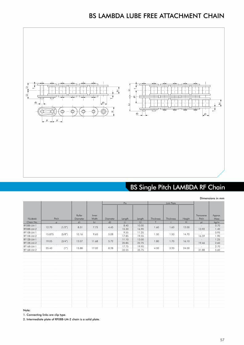
57
L2L1
d2 d1
p
HT
t
pb
1
d2 d1
T
b1
L2L1
tp
t
TSUBAKIChain No.
PitchRoller
DiameterInner Width
Pin Link Plate
Transverse Pitch
Approx. MassDiameter Length Length Thickness Thickness Height
p d1 b1 d2 L1 L2 T t H pt kg/mRF08B-LM-1
12.70 (1/2”) 8.51 7.75 4.458.40 10.00
1.60 1.60 12.00- 0.70
RF08B-LM-2 15.30 16.90 13.92 1.40RF10B-LM-1
15.875 (5/8”) 10.16 9.65 5.089.55 11.25
1.50 1.50 14.70- 0.95
RF10B-LM-2 17.85 19.55 16.59 1.90RF12B-LM-1
19.05 (3/4”) 12.07 11.68 5.7211.10 13.00
1.80 1.70 16.10- 1.25
RF12B-LM-2 20.85 22.75 19.46 2.60RF16B-LM-1
25.40 (1”) 15.88 17.02 8.2817.75 19.95
4.00 3.20 24.00- 2.70
RF16B-LM-2 33.55 35.75 31.88 5.60
Dimensions in mm
BS LAMBDA LUBE FREE ATTACHMENT CHAIN
Note:
1. Connecting links are clip type.
2. Intermediate plate of RF08B-LM-2 chain is a solid plate.
BS Single Pitch LAMBDA RF Chain
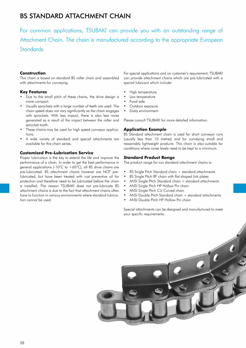
58
For common applications, TSUBAKI can provide you with an outstanding range of
Attachment Chain. The chain is manufactured according to the appropriate European
Standards.
ConstructionThis chain is based on standard BS roller chain and assembled with attachments for conveying.
Key Features• Due to the small pitch of these chains, the drive design is
more compact.• Usually sprockets with a large number of teeth are used. The
chain speed does not vary significantly as the chain engages with sprockets. With less impact, there is also less noise generated as a result of the impact between the roller and sprocket tooth.
• These chains may be used for high speed conveyor applica-tions.
• A wide variety of standard and special attachments are available for this chain series.
Customised Pre-Lubrication ServiceProper lubrication is the key to extend the life and improve the performance of a chain. In order to get the best performance in general applications (-10°C to +60°C), all BS drive chains are pre-lubricated. BS attachment chains however are NOT pre- lubricated, but have been treated with rust preventive oil for protection and therefore need to be lubricated before the chain is installed. The reason TSUBAKI does not pre-lubricate BS attachment chains is due to the fact that attachment chains often have to function in various environments where standard lubrica-tion cannot be used.
For special applications and on customer’s requirement, TSUBAKI can provide attachment chains which are pre-lubricated with a special lubricant which include:
• High temperature• Low temperature• Food safe• Outdoor exposure• Dusty environment
Please consult TSUBAKI for more detailed information.
Application Example BS Standard attachment chain is used for short conveyor runs (usually less than 10 metres) and for conveying small and rea sonably lightweight products. This chain is also suitable for conditions where noise levels need to be kept to a minimum.
Standard Product RangeThe product range for our standard attachment chains is:
• BS Single Pitch Standard chain + standard attachments• BS Single Pitch RF chain with flat shaped link plates• ANSI Single Pitch Standard chain + standard attachments• ANSI Single Pitch HP Hollow Pin chain• ANSI Single Pitch CU Curved chain• ANSI Double Pitch Standard chain + standard attachments• ANSI Double Pitch HP Hollow Pin chain
Special attachments can be designed and manufactured to meet your specific requirements.
BS STANDARD ATTACHMENT CHAIN
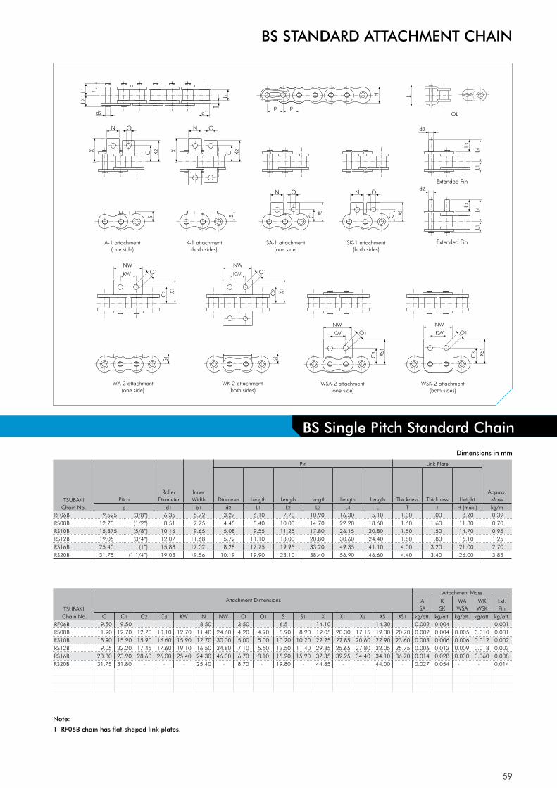
59
N O
L2L1
d2 d1p
H
T
t
p
b1
X2C
D-1 attachment
L1L4
L3
d2
D-3 attachment
L1L4
L3
d2
N O
XX2C
N O
X
S
A-1 attachment(one side)
WA-2 attachment(one side)
S
K-1 attachment(both sides)
C1
SA-1 attachment(one side)
SK-1 attachment(both sides)
XS
N O
C1 XS
X1
NWO1
C2
S1
WK-2 attachment(both sides)
X1
NW
KWKWC
2S1
WSA-2 attachment(one side)
WSK-2 attachment(both sides)
XS1
NW
KW
C3 XS
1
NW
KW
C3
O1
O1 O1
L
OL
Extended Pin
Extended Pin
Dimensions in mm
BS STANDARD ATTACHMENT CHAIN
Note:
1. RF06B chain has flat-shaped link plates.
BS Single Pitch Standard Chain
TSUBAKIChain No.
PitchRoller
DiameterInner Width
Pin Link Plate
Approx. MassDiameter Length Length Length Length Length Thickness Thickness Height
p d1 b1 d2 L1 L2 L3 L4 L T t H (max.) kg/mRF06B 9.525 (3/8”) 6.35 5.72 3.27 6.10 7.70 10.90 16.30 15.10 1.30 1.00 8.20 0.39RS08B 12.70 (1/2”) 8.51 7.75 4.45 8.40 10.00 14.70 22.20 18.60 1.60 1.60 11.80 0.70RS10B 15.875 (5/8”) 10.16 9.65 5.08 9.55 11.25 17.80 26.15 20.80 1.50 1.50 14.70 0.95RS12B 19.05 (3/4”) 12.07 11.68 5.72 11.10 13.00 20.80 30.60 24.40 1.80 1.80 16.10 1.25RS16B 25.40 (1”) 15.88 17.02 8.28 17.75 19.95 33.20 49.35 41.10 4.00 3.20 21.00 2.70RS20B 31.75 (1 1/4”) 19.05 19.56 10.19 19.90 23.10 38.40 56.90 46.60 4.40 3.40 26.00 3.85
TSUBAKI Chain No.
Attachment DimensionsAttachment Mass
ASA
KSK
WAWSA
WKWSK
Ext.Pin
C C1 C2 C3 KW N NW O O1 S S1 X X1 X2 XS XS1 kg/att. kg/att. kg/att. kg/att. kg/att.RF06B 9.50 9.50 - - - 8.50 - 3.50 - 6.5 - 14.10 - - 14.30 - 0.002 0.004 - - 0.001RS08B 11.90 12.70 12.70 13.10 12.70 11.40 24.60 4.20 4.90 8.90 8.90 19.05 20.30 17.15 19.30 20.70 0.002 0.004 0.005 0.010 0.001RS10B 15.90 15.90 15.90 16.60 15.90 12.70 30.00 5.00 5.00 10.20 10.20 22.25 22.85 20.60 22.90 23.60 0.003 0.006 0.006 0.012 0.002RS12B 19.05 22.20 17.45 17.60 19.10 16.50 34.80 7.10 5.50 13.50 11.40 29.85 25.65 27.80 32.05 25.75 0.006 0.012 0.009 0.018 0.003RS16B 23.80 23.90 28.60 26.00 25.40 24.30 46.00 6.70 8.10 15.20 15.90 37.35 39.25 34.40 34.10 36.70 0.014 0.028 0.030 0.060 0.008RS20B 31.75 31.80 - - - 25.40 - 8.70 - 19.80 - 44.85 - - 44.00 - 0.027 0.054 - - 0.014
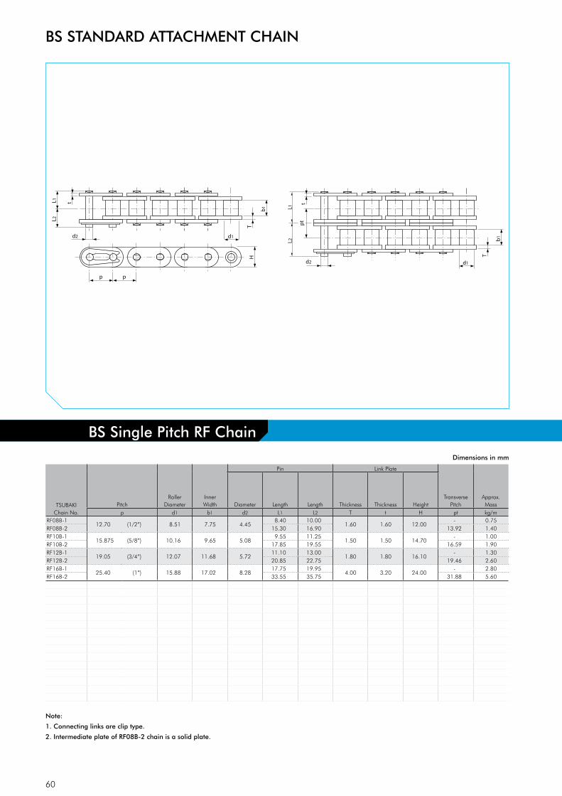
60
L2L1
d2 d1
p
HT
t
p
b1
d2 d1
T
b1
L2L1
tp
t
Dimensions in mm
TSUBAKIChain No.
PitchRoller
DiameterInner Width
Pin Link Plate
Transverse Pitch
Approx. MassDiameter Length Length Thickness Thickness Height
p d1 b1 d2 L1 L2 T t H pt kg/mRF08B-1
12.70 (1/2”) 8.51 7.75 4.458.40 10.00
1.60 1.60 12.00- 0.75
RF08B-2 15.30 16.90 13.92 1.40RF10B-1
15.875 (5/8”) 10.16 9.65 5.089.55 11.25
1.50 1.50 14.70- 1.00
RF10B-2 17.85 19.55 16.59 1.90RF12B-1
19.05 (3/4”) 12.07 11.68 5.7211.10 13.00
1.80 1.80 16.10- 1.30
RF12B-2 20.85 22.75 19.46 2.60RF16B-1
25.40 (1”) 15.88 17.02 8.2817.75 19.95
4.00 3.20 24.00- 2.80
RF16B-2 33.55 35.75 31.88 5.60
Note:
1. Connecting links are clip type.
2. Intermediate plate of RF08B-2 chain is a solid plate.
BS Single Pitch RF Chain
BS STANDARD ATTACHMENT CHAIN
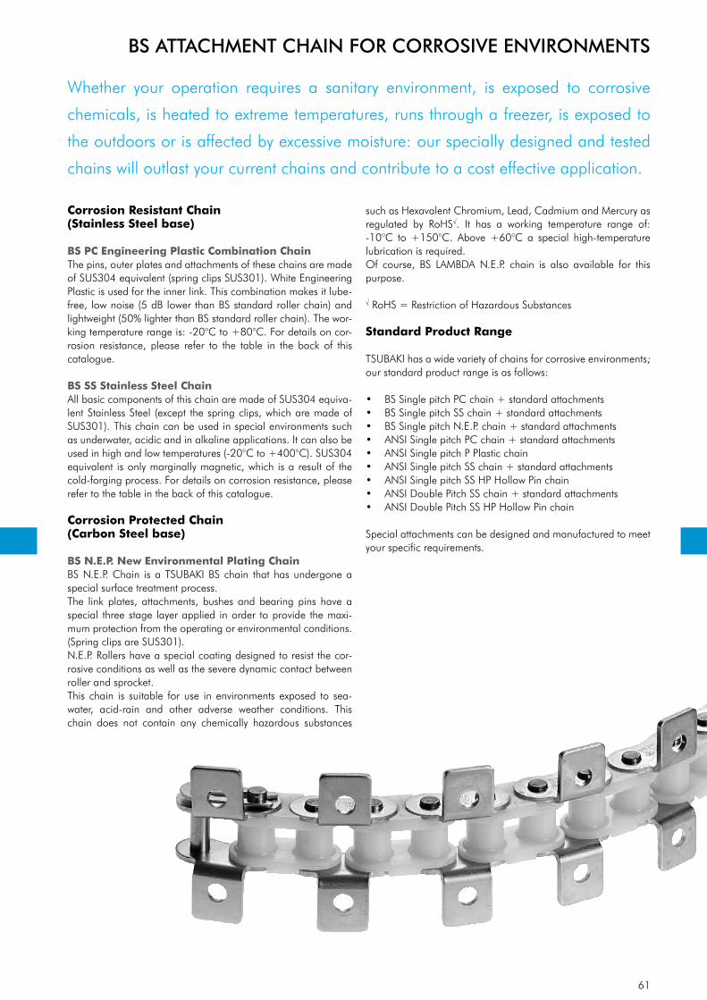
61
Whether your operation requires a sanitary environment, is exposed to corrosive
chemicals, is heated to extreme temperatures, runs through a freezer, is exposed to
the outdoors or is affected by excessive moisture: our specially designed and tested
chains will outlast your current chains and contribute to a cost effective application.
Corrosion Resistant Chain(Stainless Steel base)
BS PC Engineering Plastic Combination ChainThe pins, outer plates and attachments of these chains are made of SUS304 equivalent (spring clips SUS301). White Engineering Plastic is used for the inner link. This combination makes it lube-free, low noise (5 dB lower than BS standard roller chain) and lightweight (50% lighter than BS standard roller chain). The wor-king temperature range is: -20°C to +80°C. For details on cor-rosion resistance, please refer to the table in the back of this catalogue.
BS SS Stainless Steel ChainAll basic components of this chain are made of SUS304 equiva-lent Stainless Steel (except the spring clips, which are made of SUS301). This chain can be used in special environments such as under water, acidic and in alkaline applications. It can also be used in high and low temperatures (-20°C to +400°C). SUS304 equivalent is only marginally magnetic, which is a result of the cold-forging process. For details on corrosion resistance, please refer to the table in the back of this catalogue.
Corrosion Protected Chain(Carbon Steel base)
BS N.E.P. New Environmental Plating ChainBS N.E.P. Chain is a TSUBAKI BS chain that has undergone a special surface treatment process.The link plates, attachments, bushes and bearing pins have a special three stage layer applied in order to provide the maxi-mum protection from the operating or environmental conditions. (Spring clips are SUS301).N.E.P. Rollers have a special coating designed to resist the cor-rosive conditions as well as the severe dynamic contact between roller and sprocket.This chain is suitable for use in environments exposed to sea-water, acid-rain and other adverse weather conditions. This chain does not contain any chemically hazardous substances
such as Hexavalent Chromium, Lead, Cadmium and Mercury as regu lated by RoHS√. It has a working temperature range of: -10°C to +150°C. Above +60°C a special high-temperature lubrication is required.Of course, BS LAMBDA N.E.P. chain is also available for this purpose.
√ RoHS = Restriction of Hazardous Substances
Standard Product Range
TSUBAKI has a wide variety of chains for corrosive environments; our standard product range is as follows:
• BS Single pitch PC chain + standard attachments• BS Single pitch SS chain + standard attachments• BS Single pitch N.E.P. chain + standard attachments• ANSI Single pitch PC chain + standard attachments• ANSI Single pitch P Plastic chain• ANSI Single pitch SS chain + standard attachments• ANSI Single pitch SS HP Hollow Pin chain• ANSI Double Pitch SS chain + standard attachments• ANSI Double Pitch SS HP Hollow Pin chain
Special attachments can be designed and manufactured to meet your specific requirements.
BS ATTACHMENT CHAIN FOR CORROSIVE ENVIRONMENTS

62
L2L1
d2p
H
T
t
p
b1
d1
p p
N O
C X C X
A-1 attachment(one side)
S
p p
N O
K-1 attachment(both sides)
S
N O
C1
XS
L4
L3
L4
L1 L1
L3
p p
N O
C1 XS
p p
SA-1 attachment(one side)
SK-1 attachment(both sides)
D-1 attachment D-3 attachment
L4
L3
L4
L1 L1
L3
Extended Pin Extended Pin
Dimensions in mm
TSUBAKIChain No.
PitchBush
DiameterInner Width
Pin Link PlateMax.
Allowable Load
acc. to Tsubaki
Approx. MassDiameter Length Length Length Length Thickness Thickness Height
p d1 b1 d2 L1 L2 L3 L4 T t H (max.) kN kg/mRF06B-PC 9.525 (3/8”) 6.35 5.72 3.28 6.50 7.25 11.30 16.65 1.30 1.00 8.20 0.20 0.23RS08B-PC 12.70 (1/2”) 8.51 7.75 4.45 8.35 10.05 14.90 22.25 1.60 1.50 12.00 0.46 0.40RS10B-PC 15.875 (5/8”) 10.16 9.65 5.08 9.55 11.25 17.80 26.15 1.50 1.50 14.70 0.53 0.51RS12B-PC 19.05 (3/4”) 12.07 11.68 5.72 11.10 13.00 20.90 30.70 1.80 1.80 16.10 0.70 0.67
BS ATTACHMENT CHAIN FOR CORROSIVE ENVIRONMENTS
TSUBAKIChain No.
Attachment DimensionsAttachment Mass
ASA
KSK
Ext.Pin
C C1 N O S X XS kg/att. kg/att. kg/att.RF06B-PC 9.50 9.50 8.50 3.50 6.50 14.10 14.30 0.002 0.004 0.001RS08B-PC 11.90 12.70 11.40 4.20 8.90 19.05 19.30 0.002 0.004 0.001RS10B-PC 15.90 15.90 12.70 5.00 10.20 22.25 22.95 0.003 0.006 0.002RS12B-PC 19.05 22.20 16.50 7.10 13.50 29.85 32.30 0.006 0.012 0.003
Note:
1. Make sure to check the chain load again when replacing Stainless Steel Chain with PC Chain.
2. Offset links are not available.
3. Use a chain tensioner with an idler sprocket to adjust chain tension.
4. Guide rails should support the underside of the inner links.
5. For details on corrosion resistance selection, please consult our Corrosion Resistance Guide in this catalogue.
BS Single Pitch PC Chain
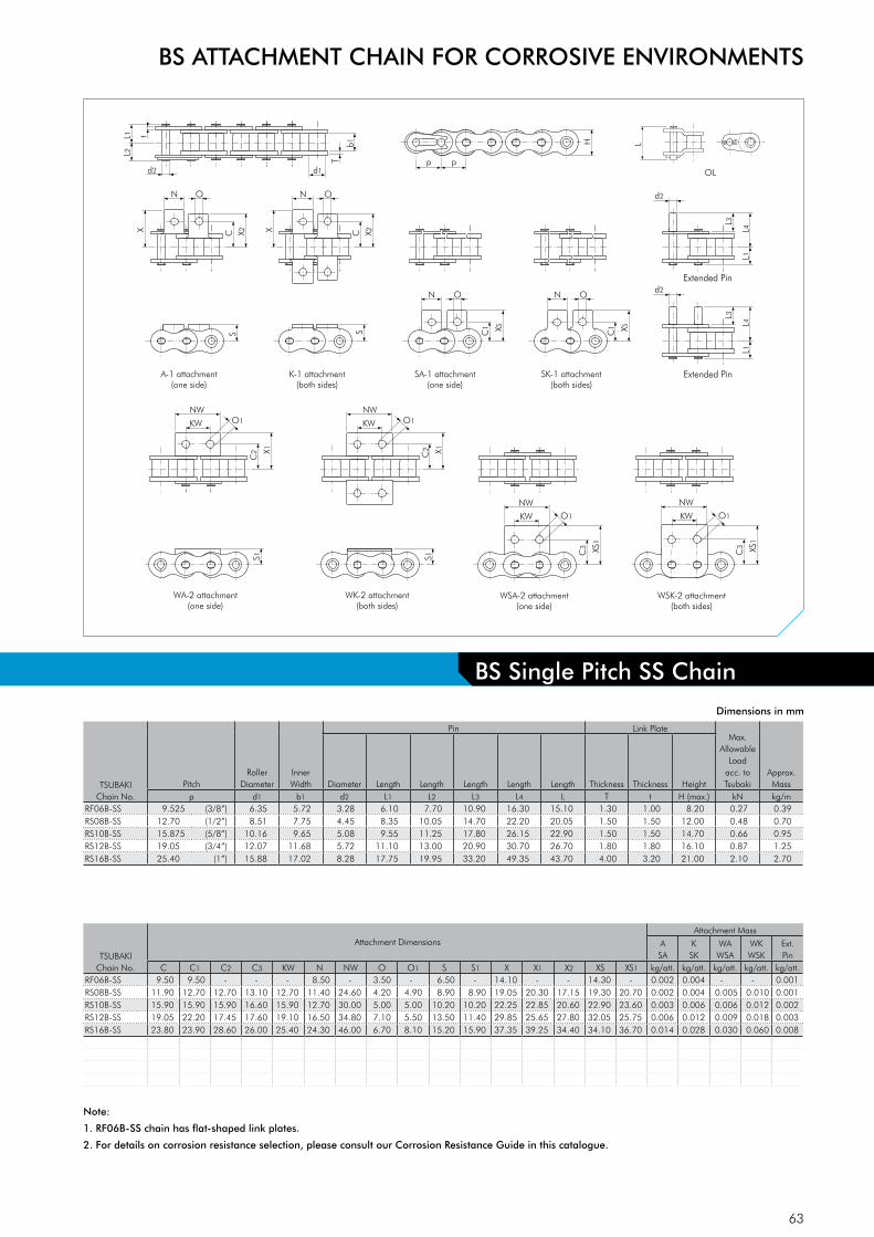
63
N O
L2L1
d2 d1p
H
T
t
p
b1
X2C
D-1 attachment
L1L4
L3
d2
D-3 attachment
L1L4
L3
d2
N O
XX2C
N O
X
S
A-1 attachment(one side)
WA-2 attachment(one side)
S
K-1 attachment(both sides)
C1
SA-1 attachment(one side)
SK-1 attachment(both sides)
XS
N O
C1 XS
X1
NWO1
C2
S1
WK-2 attachment(both sides)
X1
NW
KWKWC
2S1
WSA-2 attachment(one side)
WSK-2 attachment(both sides)
XS1
NW
KW
C3 XS
1
NW
KW
C3
O1
O1 O1
L
OL
Extended Pin
Extended Pin
Dimensions in mm
TSUBAKIChain No.
Attachment DimensionsAttachment Mass
ASA
KSK
WAWSA
WKWSK
Ext.Pin
C C1 C2 C3 KW N NW O O1 S S1 X X1 X2 XS XS1 kg/att. kg/att. kg/att. kg/att. kg/att.RF06B-SS 9.50 9.50 - - - 8.50 - 3.50 - 6.50 - 14.10 - - 14.30 - 0.002 0.004 - - 0.001RS08B-SS 11.90 12.70 12.70 13.10 12.70 11.40 24.60 4.20 4.90 8.90 8.90 19.05 20.30 17.15 19.30 20.70 0.002 0.004 0.005 0.010 0.001RS10B-SS 15.90 15.90 15.90 16.60 15.90 12.70 30.00 5.00 5.00 10.20 10.20 22.25 22.85 20.60 22.90 23.60 0.003 0.006 0.006 0.012 0.002RS12B-SS 19.05 22.20 17.45 17.60 19.10 16.50 34.80 7.10 5.50 13.50 11.40 29.85 25.65 27.80 32.05 25.75 0.006 0.012 0.009 0.018 0.003RS16B-SS 23.80 23.90 28.60 26.00 25.40 24.30 46.00 6.70 8.10 15.20 15.90 37.35 39.25 34.40 34.10 36.70 0.014 0.028 0.030 0.060 0.008
Note:
1. RF06B-SS chain has flat-shaped link plates.
2. For details on corrosion resistance selection, please consult our Corrosion Resistance Guide in this catalogue.
BS Single Pitch SS Chain
BS ATTACHMENT CHAIN FOR CORROSIVE ENVIRONMENTS
TSUBAKIChain No.
PitchRoller
DiameterInner Width
Pin Link PlateMax.
Allowable Load
acc. to Tsubaki
Approx. MassDiameter Length Length Length Length Length Thickness Thickness Height
p d1 b1 d2 L1 L2 L3 L4 L T t H (max.) kN kg/mRF06B-SS 9.525 (3/8”) 6.35 5.72 3.28 6.10 7.70 10.90 16.30 15.10 1.30 1.00 8.20 0.27 0.39RS08B-SS 12.70 (1/2”) 8.51 7.75 4.45 8.35 10.05 14.70 22.20 20.05 1.50 1.50 12.00 0.48 0.70RS10B-SS 15.875 (5/8”) 10.16 9.65 5.08 9.55 11.25 17.80 26.15 22.90 1.50 1.50 14.70 0.66 0.95RS12B-SS 19.05 (3/4”) 12.07 11.68 5.72 11.10 13.00 20.90 30.70 26.70 1.80 1.80 16.10 0.87 1.25RS16B-SS 25.40 (1”) 15.88 17.02 8.28 17.75 19.95 33.20 49.35 43.70 4.00 3.20 21.00 2.10 2.70
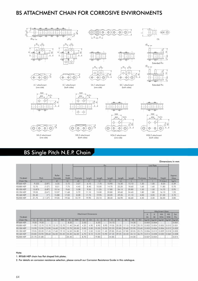
64
N O
L2L1
d2 d1p
H
T
t
p
b1
X2C
D-1 attachment
L1L4
L3
d2
D-3 attachment
L1L4
L3
d2
N O
XX2C
N O
X
S
A-1 attachment(one side)
WA-2 attachment(one side)
S
K-1 attachment(both sides)
C1
SA-1 attachment(one side)
SK-1 attachment(both sides)
XS
N O
C1 XS
X1
NWO1
C2
S1
WK-2 attachment(both sides)
X1
NW
KWKWC
2S1
WSA-2 attachment(one side)
WSK-2 attachment(both sides)
XS1
NW
KW
C3 XS
1
NW
KW
C3
O1
O1 O1
L
OL
Extended Pin
Extended Pin
Dimensions in mm
Note:
1. RF06B-NEP chain has flat shaped link plates.
2. For details on corrosion resistance selection, please consult our Corrosion Resistance Guide in this catalogue.
BS Single Pitch N.E.P. Chain
BS ATTACHMENT CHAIN FOR CORROSIVE ENVIRONMENTS
TSUBAKIChain No.
PitchRoller
DiameterInner Width
Pin Link Plate
Approx. MassDiameter Length Length Length Length Length Thickness Thickness Height
p d1 b1 d2 L1 L2 L3 L4 L T t H (max.) kg/mRF06B-NEP 9.525 (3/8”) 6.35 5.72 3.27 6.10 7.70 10.90 16.30 15.10 1.30 1.00 8.20 0.39RS08B-NEP 12.70 (1/2”) 8.51 7.75 4.45 8.40 10.00 14.70 22.20 18.60 1.60 1.60 11.80 0.70RS10B-NEP 15.875 (5/8”) 10.16 9.65 5.08 9.55 11.25 17.80 26.15 20.80 1.50 1.50 14.70 0.95RS12B-NEP 19.05 (3/4”) 12.07 11.68 5.72 11.10 13.00 20.80 30.60 24.40 1.80 1.80 16.10 1.25RS16B-NEP 25.40 (1”) 15.88 17.02 8.28 17.75 19.95 33.20 49.35 41.10 4.00 3.20 21.00 2.70RS20B-NEP 31.75 (1 1/4”) 19.05 19.56 10.19 19.90 23.10 38.40 56.90 46.60 4.40 3.40 26.00 3.85
TSUBAKIChain No.
Attachment DimensionsAttachment Mass
ASA
KSK
WAWSA
WKWSK
Ext.Pin
C C1 C2 C3 KW N NW O O1 S S1 X X1 X2 XS XS1 kg/att. kg/att. kg/att. kg/att. kg/att.RF06B-NEP 9.50 9.50 - - - 8.50 - 3.50 - 6.50 - 14.10 - - 14.30 - 0.002 0.004 - - 0.001RS08B-NEP 11.90 12.70 12.70 13.10 12.70 11.40 24.60 4.20 4.90 8.90 8.90 19.05 20.30 17.15 19.30 20.70 0.002 0.004 0.005 0.010 0.001RS10B-NEP 15.90 15.90 15.90 16.60 15.90 12.70 30.00 5.00 5.00 10.20 10.20 22.25 22.85 20.60 22.90 23.60 0.003 0.006 0.006 0.012 0.002RS12B-NEP 19.05 22.20 17.45 17.60 19.10 16.50 34.80 7.10 5.50 13.50 11.40 29.85 25.65 27.80 32.05 25.75 0.006 0.012 0.009 0.018 0.003RS16B-NEP 23.80 23.90 28.60 26.00 25.40 24.30 46.00 6.70 8.10 15.20 15.90 37.35 39.25 34.40 34.10 36.70 0.014 0.028 0.030 0.060 0.008RS20B-NEP 31.75 31.80 - - - 25.40 - 8.70 - 19.80 - 44.85 - - 44.00 - 0.027 0.054 - - 0.014

65
Special Coated PinSpecial Oil ImpregnatedSintered Bush
Ring Coin
Roller
TSUBAKI’s LAMBDA Chains were the first in the industry to use a special oil- im-
pregnated bush. Since their launch in 1988, they have been adopted for diverse
industries and applications, and their performance has been highly rated. TSUBAKI
has a wide line-up of lube-free, long life products that help customers reduce costs.
Technical EvolutionAs a pioneer in the lube-free chain market, TSUBAKI will reveal some of the key elements behind ANSI LAMBDA’s outstanding performance:
Sintered BushA special oil-impregnated sintered bush in combination with a special coated pin for long-term internal lubrication is the secret of TSUBAKI ANSI LAMBDA’s long economic life and wear resi-stance.
Temperature and LubricationTSUBAKI ANSI LAMBDA has outstanding performance in tempe-ratures up to +150°C.
For temperatures above +150°C: Due to the special NSF-H1 certified lubrication impregnated bushes, TSUBAKI ANSI LAMBDA KF Series is usable in a wide temperature range (from -10°C to +230°C), and for food product applications while at the same time being kind to the environment.Please consult TSUBAKI for more detailed information.
Fig. 23 Basic Construction
AdvantagesTSUBAKI has enhanced the ANSI LAMBDA with the following advantages:
Save Maintenance CostsNo expensive labour costs as it is not required to manually lubri-cate this chain.
Save Purchasing CostsLower frequency of purchasing due to the high quality of the chain and its long economic life. No purchasing of lubricants or lubrication systems necessary.
Higher ProductivityNo unforeseen downtime due to chain breakage.Less time required for maintenance and therefore more time for production.
Environmental FriendlyApplications run clean thus reducing the risk of contaminating products, machines, floor etc.
Inter-ChangeabilityANSI LAMBDA Attachment chain is interchangeable with standard ANSI roller chains. However, as the pins are longer than those of the standard ANSI roller chain, please make sure that there is no interference with the machine.
Standard Product RangeThe product range for our standard LAMBDA attachment chains is:• ANSI Single Pitch LAMBDA chain + standard attachments• ANSI Single Pitch LAMBDA HP Hollow Pin chain• ANSI Double Pitch LAMBDA chain• BS Single Pitch LAMBDA chain + standard attachments• BS Single Pitch LAMBDA RF chain with flat shaped link plates
Special attachments can be designed and manufactured to meet your specific requirements.
ANSI LAMBDA LUBE FREE ATTACHMENT CHAIN
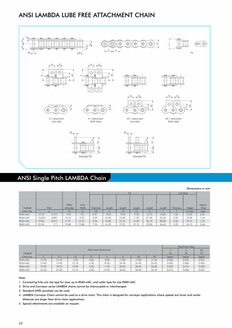
66
N O
L2
L1
d2 d1 p
H
T
T
p
b1
X2C
D-1 attachment
L1
L4 L3
d2
D-3 attachment
L1
L4 L3
d2
N O
X X2C
N O
X
S
A-1 attachment (one side)
S
K-1 attachment (both sides)
C1
SA-1 attachment (one side)
SK-1 attachment (both sides)
XS
N O
C1 XS
L
OL
Extended Pin Extended Pin
TSUBAKIChain No.
PitchRoller
DiameterInner Width
Pin Link Plate
Approx. MassDiameter Length Length Length Length Length Thickness Height
p d1 b1 d2 L1 L2 L3 L4 L T H (max.) kg/mRS40-LMC 12.70 (1/2”) 7.92 7.95 3.97 8.25 9.95 9.50 16.75 18.20 1.50 12.00 0.64RS50-LMC 15.875 (5/8”) 10.16 9.53 5.09 10.30 12.00 11.90 21.00 22.60 2.00 15.00 1.04RS60-LMC 19.05 (3/4”) 11.91 12.70 5.96 12.85 14.75 14.30 25.75 28.20 2.40 18.10 1.53RS80-LMC 25.40 (1”) 15.88 15.88 7.94 16.25 19.25 19.10 33.85 36.60 3.20 24.10 2.66
TSUBAKIChain No.
Attachment DimensionsAttachment Mass
ASA
KSK
Ext. Pin
C C1 N O S X X2 XS kg/att. kg/att. kg/att.RS40-LMC 12.70 12.70 9.50 3.60 8.00 17.80 17.80 17.40 0.002 0.004 0.001RS50-LMC 15.90 15.90 12.70 5.20 10.30 23.40 23.40 23.05 0.003 0.006 0.002RS60-LMC 19.05 18.30 15.90 5.20 11.90 28.20 28.20 26.85 0.007 0.014 0.003RS80-LMC 25.40 24.60 19.10 6.80 15.90 36.60 36.60 35.45 0.013 0.026 0.007
Dimensions in mm
ANSI LAMBDA LUBE FREE ATTACHMENT CHAIN
Note:
1. Connecting links are clip type for sizes up to RS60-LMC, and cotter type for size RS80-LMC.
2. Drive and Conveyor series LAMBDA chains cannot be intercoupled or interchanged.
3. Standard ANSI sprockets can be used.
4. LAMBDA Conveyor Chain cannot be used as a drive chain. This chain is designed for conveyor applications where speeds are lower and center
distances are larger than drive chain applications.
5. Special attachments are available on request.
ANSI Single Pitch LAMBDA Chain

67
HHp
d1d2 d8
L1L2
T
b1
p p
OL
T
L
TSUBAKIChain No.
PitchBush
DiameterInner Width
Pin Link Plate
Approx. MassDiameter Hollow Pin Length Length Length Thickness Height
p d1 b1 d2 d8 L1 L2 L T H (max.) kg/mRS40-LMC-HP 12.70 (1/2”) 7.92 7.95 5.68 4.00 8.00 9.50 19.10 1.50 12.00 0.53RS50-LMC-HP 15.875 (5/8”) 10.16 9.53 7.22 5.12 10.05 11.65 23.40 2.00 15.00 0.86RS60-LMC-HP 19.05 (3/4”) 11.91 12.70 8.38 5.99 12.55 14.25 28.70 2.40 18.10 1.27
Dimensions in mm
ANSI Single Pitch LAMBDA Hollow Pin (HP) Chain
ANSI LAMBDA LUBE FREE ATTACHMENT CHAIN
Note:
1. ANSI LMC-HP chain is rollerless chain (only bush).

68
L2
L1
d2 d1
T
T
b1
S type roller
R type roller
OL
OL
p
H
p
L2
L1
d2 d4
T
T
b1
p
H
p
L
p
L
p
TSUBAKIChain No.
PitchInner Width
Roller Pin Link Plate Approx. Mass
S Roller R Roller Diameter Length Length Length Thickness Height S Roller R Rollerp b1 d1 d4 d2 L1 L2 L T H kg/m kg/m
RF2040-LMC 25.40 (1”) 7.95 7.92 15.88 3.97 8.25 9.95 18.20 1.50 12.00 0.51 0.87RF2050-LMC 31.75 (1 1/4”) 9.53 10.16 19.05 5.09 10.30 12.00 22.60 2.00 15.00 0.84 1.30RF2060-LMC 38.10 (1 1/2”) 12.70 11.91 22.23 5.96 14.55 16.55 31.50 3.20 17.20 1.51 2.19
Dimensions in mm
Note:
1. Connecting links are clip type.
2. LAMBDA Conveyor Chain cannot be used as a drive chain. This chain is designed for conveyor applications where speeds are lower and
center distances are larger than drive chain applications.
3. Special attachments are available on request.
4. Chain with S type roller is indicated as RF2040S-LMC.
5. Chain with R type roller is indicated as RF2040R-LMC.
ANSI Double Pitch LAMBDA Chain
ANSI LAMBDA LUBE FREE ATTACHMENT CHAIN

69
For standard applications, TSUBAKI can provide you with an outstanding Attachment
Chain. This chain is manufactured in accordance with the American Standards.
Fig. 24 K-1 Attachment
ConstructionThis chain is based on standard ANSI roller chain with attach-ments added for conveying.
Key Features• Due to the small pitch of these chains, the drive design is
smaller. • Usually sprockets with a large number of teeth are used. The
chain speed does not vary significantly as the chain engages with sprockets. With less impact, there is also less noise generated as a result of the impact between the roller and sprocket tooth.
• These chains may be used for high-speed conveyors.• A wide variety of standard attachments and special attach-
ments is available for this chain series.
Customised Pre-Lubrication ServiceProper lubrication is the key to extend the life and improve the performance of a chain. In order to get the best performance in general applications (-10°C to +60°C), all ANSI drive chains are pre-lubricated. ANSI attachment chains however are NOT pre-lubricated, but have been treated with rust preventive oil and therefore need to be lubricated before the installation of the chain. The reason for TSUBAKI not to lubricate the ANSI attach-ment chains is due to the fact that attachment chains often have to function in various environments where standard lubrication cannot be used.
For special applications, TSUBAKI can provide attachment chains, pre-lubricated with a special lubricant at the customer’s request.
• High temperature• Low temperature• Food safe• Outdoor exposure• Dusty environment
Please consult TSUBAKI for more detailed information.
Application ExampleANSI Standard attachment chain is used for short conveyors of usually less than 10 metres for small and light products. This chain is also suitable for conditions under which noise should be avoided.
Standard Product RangeThe product range for our standard attachment chains is:• ANSI Single Pitch Standard chain + standard attachments• ANSI Single Pitch HP Hollow Pin chain• ANSI Single Pitch CU Curved chain• ANSI Double Pitch Standard chain + standard attachments• ANSI Double Pitch HP Hollow Pin chain• BS Single Pitch Standard chain + standard attachments• BS Single Pitch RF chain with flat shaped link plates
Special attachments can be designed and manufactured to meet your specific requirements.
Fig. 25 Double Pitch A-2 Attachment
ANSI STANDARD ATTACHMENT CHAIN
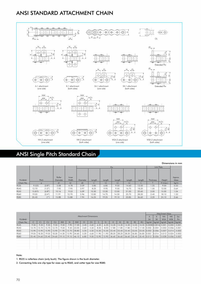
70
N O
L2
L1
d2 d1 p
H
T
T
p
b1
X2C
D-1 attachment
L1
L4 L3
d2
D-3 attachment
L1
L4 L3
d2
N O
X X2C
N O
X
S S
A-1 attachment (one side)
K-1 attachment (both sides)
C1
SA-1 attachment (one side)
SK-1 attachment (both sides)
XS
N O
C1 XS
WA-2 attachment
(one side)
X1
NW
KW
C2
WK-2 attachment (both sides)
X1
NW
KW
C2
WSA-2 attachment (one side)
WSK-2 attachment (both sides)
XS1
NW
KW
C3 XS
1
NW
KW
C3
O1 O1
O1 O1
S1
S1
L
OL
TSUBAKIChain No.
PitchRoller
DiameterInner Width
Pin Link Plate
Approx. MassDiameter Length Length Length Length Length Thickness Height
p d1 b1 d2 L1 L2 L3 L4 L T H (max.) kg/mRS35 9.525 (3/8”) 5.08 4.78 3.59 5.85 6.85 9.50 14.60 13.50 1.25 9.00 0.33RS40 12.70 (1/2”) 7.92 7.95 3.97 8.25 9.95 9.50 16.75 18.20 1.50 12.00 0.64RS50 15.875 (5/8”) 10.16 9.53 5.09 10.30 12.00 12.00 21.00 22.60 2.00 15.00 1.04RS60 19.05 (3/4”) 11.91 12.70 5.96 12.85 14.75 14.30 25.75 28.20 2.40 18.10 1.53RS80 25.40 (1”) 15.88 15.88 7.94 16.25 19.25 19.10 33.85 36.60 3.20 24.10 2.66
TSUBAKIChain No.
Attachment DimensionsAttachment Mass
ASA
KSK
WAWSA
WKWSK
Ext.Pin
C C1 C2 C3 KW N NW O O1 S S1 X X1 X2 XS XS1 kg/att. kg/att. kg/att. kg/att. kg/att.RS35 9.50 9.50 9.50 9.50 9.50 7.90 17.30 3.40 2.60 6.35 6.35 14.30 14.30 14.30 14.55 14.55 0.0008 0.0016 0.001 0.002 0.001RS40 12.70 12.70 12.70 12.70 9.50 9.50 23.00 3.60 4.50 8.00 8.00 17.80 17.80 17.80 17.40 17.40 0.002 0.004 0.003 0.006 0.001RS50 15.90 15.90 15.90 15.90 11.90 12.70 28.80 5.20 5.50 10.30 10.30 23.40 23.40 23.40 23.05 23.05 0.003 0.006 0.007 0.014 0.002RS60 19.05 18.30 19.05 18.30 14.30 15.90 34.60 5.20 6.60 11.90 11.90 28.20 28.20 28.20 26.85 26.85 0.007 0.014 0.012 0.024 0.003RS80 25.40 24.60 25.40 24.60 19.10 19.10 46.10 6.80 9.00 15.90 15.90 36.60 36.60 36.60 35.45 35.45 0.013 0.026 0.028 0.056 0.007
Dimensions in mm
ANSI STANDARD ATTACHMENT CHAIN
Note:
1. RS35 is rollerless chain (only bush). The figure shown is the bush diameter.
2. Connecting links are clip type for sizes up to RS60, and cotter type for size RS80.
ANSI Single Pitch Standard Chain
Extended Pin
Extended Pin

71
HHp
d1d2 d8
L1L2
T
b1
p p
OL
T
L
TSUBAKIChain No.
PitchBush
DiameterInner Width
Pin Link Plate
Approx.MassDiameter Hollow Pin Length Length Length Thickness Height
p d1 b1 d2 d8 L1 L2 L T H (max.) kg/mRS40-HP 12.70 (1/2”) 7.92 7.95 5.68 4.00 8.00 9.50 19.10 1.50 12.00 0.53RS50-HP 15.875 (5/8”) 10.16 9.53 7.22 5.12 10.05 11.65 23.40 2.00 15.00 0.86RS60-HP 19.05 (3/4”) 11.91 12.70 8.38 5.99 12.55 14.25 28.70 2.40 18.10 1.27RS80-HP 25.40 (1”) 15.88 15.88 11.38 8.02 16.25 17.80 35.70 3.20 24.10 2.15
Dimensions in mm
ANSI Single Pitch Hollow Pin (HP) Chain
ANSI STANDARD ATTACHMENT CHAIN
Note:
1. ANSI HP chain is rollerless chain (only bush).

72
L2L1
d2 d1
pH
T
T
p
b1
r
N O
L2L1
d2 d1p
H
T
T
p
b1
X2C
D-1 attachment
L1L4
L3
d2
D-3 attachment
L1L4
L3
d2
N O
XX2C
N O
X
S
A-1 attachment(one side)
S
K-1 attachment(both sides)
C1
SA-1 attachment(one side)
SK-1 attachment(both sides)
XS
N OC
1 XS
L
OL
TSUBAKIChain No.
PitchRoller
DiameterInner Width
Pin Link Plate
Minimum Bending Radius
Approx. MassDiameter Length Length Thickness Height
p d1 b1 d2 L1 L2 T H (max.) r kg/mRS40-CU 12.70 (1/2”) 7.92 7.95 3.97 8.45 9.75 1.50 12.00 350 0.61RS50-CU 15.875 (5/8”) 10.16 9.53 5.09 10.60 12.40 2.00 15.00 400 1.01RS60-CU 19.05 (3/4”) 11.91 12.70 5.96 13.25 15.05 2.40 18.10 500 1.40RS80-CU 25.40 (1”) 15.88 15.88 7.94 16.75 20.05 3.20 24.10 600 2.47
Dimensions in mm
ANSI Single Pitch Curved (CU) Chain
ANSI STANDARD ATTACHMENT CHAIN
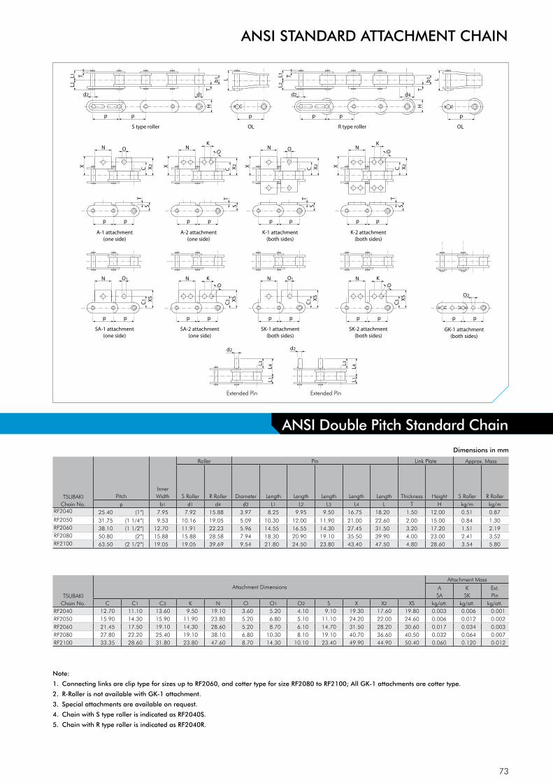
73
L2L1
d2 d1
T
T
b1
X2
CN
X
S type roller OL OLR type roller
p
H
p
L2L1
d2 d4
T
T
b1
p
H
p
ST
S
T
S
T
S
T
p p
A-1 attachment(one side)
X2
C
NK
X
p p
A-2 attachment(one side)
X2
C
N
X
p p
K-1 attachment(both sides)
X2
C
N
X
O
p p
K-2 attachment(both sides)
OOK
OX
SC
1
N O1 N
p p
SA-1 attachment(one side)
XS
C3
p p
SA-2 attachment(one side)
XS
C1
N O1 N
p p
SK-1 attachment(both sides)
XS
C3
p p
SK-2 attachment(both sides)
D-1 attachment
L1L4
L3
d2
D-3 attachment
L1L4
L3d2
p p
GK-1 attachment(both sides)
O2
KO
KO
L
p
L
p
Dimensions in mm
TSUBAKIChain No.
PitchInner Width
Roller Pin Link Plate Approx. Mass
S Roller R Roller Diameter Length Length Length Length Length Thickness Height S Roller R Rollerp b1 d1 d4 d2 L1 L2 L3 L4 L T H kg/m kg/m
RF2040 25.40 (1”) 7.95 7.92 15.88 3.97 8.25 9.95 9.50 16.75 18.20 1.50 12.00 0.51 0.87RF2050 31.75 (1 1/4”) 9.53 10.16 19.05 5.09 10.30 12.00 11.90 21.00 22.60 2.00 15.00 0.84 1.30RF2060 38.10 (1 1/2”) 12.70 11.91 22.23 5.96 14.55 16.55 14.30 27.45 31.50 3.20 17.20 1.51 2.19RF2080 50.80 (2”) 15.88 15.88 28.58 7.94 18.30 20.90 19.10 35.50 39.90 4.00 23.00 2.41 3.52RF2100 63.50 (2 1/2”) 19.05 19.05 39.69 9.54 21.80 24.50 23.80 43.40 47.50 4.80 28.60 3.54 5.80
TSUBAKIChain No.
Attachment DimensionsAttachment Mass
ASA
KSK
Ext.Pin
C C1 C3 K N O O1 O2 S X X2 XS kg/att. kg/att. kg/att.RF2040 12.70 11.10 13.60 9.50 19.10 3.60 5.20 4.10 9.10 19.30 17.60 19.80 0.003 0.006 0.001RF2050 15.90 14.30 15.90 11.90 23.80 5.20 6.80 5.10 11.10 24.20 22.00 24.60 0.006 0.012 0.002RF2060 21.45 17.50 19.10 14.30 28.60 5.20 8.70 6.10 14.70 31.50 28.20 30.60 0.017 0.034 0.003RF2080 27.80 22.20 25.40 19.10 38.10 6.80 10.30 8.10 19.10 40.70 36.60 40.50 0.032 0.064 0.007RF2100 33.35 28.60 31.80 23.80 47.60 8.70 14.30 10.10 23.40 49.90 44.90 50.40 0.060 0.120 0.012
Note:
1. Connecting links are clip type for sizes up to RF2060, and cotter type for size RF2080 to RF2100; All GK-1 attachments are cotter type.
2. R-Roller is not available with GK-1 attachment.
3. Special attachments are available on request.
4. Chain with S type roller is indicated as RF2040S.
5. Chain with R type roller is indicated as RF2040R.
ANSI Double Pitch Standard Chain
ANSI STANDARD ATTACHMENT CHAIN
Extended Pin Extended Pin

74
L
L2L1
d2 d8 d1
T
TT
b1
p
H
p p
L
L2L1
d2 d8 d4
T
b1p
H
p p
S type bush OL
OLR type roller
TSUBAKIChain No.
PitchInner Width
Pin Link Plate Approx. Mass
S Bush R Roller Diameter Hollow Pin Length Length Length Thickness Height S Bush R Rollerp b1 d1 d4 d2 d8 L1 L2 L T H kg/m kg/m
RF2040-HP 25.40 (1”) 7.95 7.92 15.88 5.68 4.00 8.00 9.50 19.10 1.50 12.00 0.46 0.82RF2050-HP 31.75 (1 1/4”) 9.53 10.16 19.05 7.22 5.12 10.05 11.65 23.40 2.00 15.00 0.75 1.21RF2060-HP 38.10 (1 1/2”) 12.70 11.91 22.23 8.38 5.99 12.55 14.25 28.70 2.40 17.20 1.38 2.06RF2080-HP 50.80 (2”) 15.88 15.88 28.58 11.38 8.02 16.25 17.80 35.70 3.20 23.00 1.80 2.81
Dimensions in mm
ANSI Double Pitch Hollow Pin (HP) Chain
ANSI STANDARD ATTACHMENT CHAIN
Note:
1. Chain with S type bush is indicated as RF2040S-HP.
2. Chain with R type roller is indicated as RF2040R-HP.

75
Whether your operation requires a sanitary environment, is exposed to corrosive
chemicals, is heated to extreme temperatures, runs through a freezer, is exposed to
the outdoors or is affected by excessive moisture: our specially designed and tested
chains will outlast your current chains and contribute to a cost effective application.
Corrosion Resistant Chain(Engineering Plastic base)
ANSI P Plastic ChainANSI P Chain consists of polyacetal chain links and SUS304 equivalent stainless steel pins and operates with standard roller chain sprockets. Based on power transmission roller chain, TSUBAKI ANSI P chain has a flat top side for conveying use. The combination of engineering plastic and stainless steel makes it a lube-free operation chain. For special environments special plas-tics are available on request (electro-conductive, chemical resi-stant and heat resistant series). The working temperature range is: -20°C to +80°C. For details on corrosion resistance, please refer to the table in the back of this catalogue.
Fig. 26 ANSI P Chain
Corrosion Resistant Chain(Stainless Steel base)
ANSI PC Engineering Plastic Combination ChainThe pins, outer plates and attachments of these chains are made of SUS304 equivalent (spring clips SUS301). White Engineering Plastic is used for the inner link. This combination makes it lube-free, low noise (5 dB lower than ANSI standard roller chain) and lightweight (50% lighter than ANSI standard roller chain). The working temperature range is: -20°C to +80°C. For details on corrosion resistance, please refer to the table in the back of this catalogue.
ANSI SS Stainless Steel ChainAll basic components of this chain are made of SUS304 equiva-lent Stainless Steel (except the spring clips, which are made of SUS301). This chain can be used in special environments such as under water, acidic and alkaline applications. It can also be used in high and low temperatures (-20°C to +400°C). SUS304 equivalent is only marginally magnetic, which is a result of the cold-forging process. For details on corrosion resistance, please refer to the table in the back of this catalogue.
Standard Product RangeTSUBAKI has a wide variety of chains for corrosive environments; our standard product range is as follows:
• ANSI Single pitch PC chain + standard attachments• ANSI Single pitch P Plastic chain• ANSI Single pitch SS chain + standard attachments• ANSI Single pitch SS HP Hollow Pin chain• ANSI Double Pitch SS chain + standard attachments• ANSI Double Pitch SS HP Hollow Pin chain• BS Single pitch PC chain + standard attachments• BS Single pitch SS chain + standard attachments• BS Single pitch N.E.P. chain + standard attachments
Special attachments can be designed and manufactured to meet your specific requirements.
ANSI ATTACHMENT CHAIN FOR CORROSIVE ENVIRONMENTS

76
d1
b1
Travel Directionp
H
H1
H2
p
L
d2
TSUBAKIChain No.
PitchBush
DiameterInner Width
Pin Chain Height
Approx. MassDiameter Length Height Height Height
p d1 b1 d2 L H H1 H2 kg/mRSP-40 12.70 (1/2”) 7.92 7.95 4.00 20.00 12.70 6.00 6.70 0.36RSP-60 19.05 (3/4”) 11.91 12.70 6.00 30.00 17.30 8.50 8.80 0.72
Dimensions in mm
ANSI ATTACHMENT CHAIN FOR CORROSIVE ENVIRONMENTS
Note:
1. Standard ANSI sprockets can be used.
2. For details on corrosion resistance selection, please consult our Corrosion Resistance Guide in this catalogue.
ANSI Single Pitch P Chain

77
L2L1
d2p
H
T
t
p
b1
d1
p p
N O
C X C X
A-1 attachment(one side)
S
p p
N O
K-1 attachment(both sides)
S
N O
C1
XS
L4
L3
L4
L1 L1
L3
p p
N O
C1 XS
p p
SA-1 attachment(one side)
SK-1 attachment(both sides)
D-1 attachment D-3 attachment
TSUBAKIChain No.
PitchBush
DiameterInner Width
Pin Link PlateMax.
Alowable. Load
acc. to Tsubaki
Approx. MassDiameter Length Length Length Length Thickness Thickness Height
p d1 b1 d2 L1 L2 L3 L4 T t H (max.) kN kg/mRS25-PC 6.35 (1/4”) 3.30 3.18 2.31 4.50 5.50 - - 1.30 0.75 6.00 0.08 0.095RS35-PC 9.525 (3/8”) 5.08 4.78 3.59 6.85 7.85 - - 2.20 1.25 9.00 0.18 0.22RS40-PC 12.70 (1/2”) 7.92 7.95 3.97 8.25 9.95 9.40 16.75 1.50 1.50 12.00 0.44 0.39RS50-PC 15.875 (5/8”) 10.16 9.53 5.09 10.30 12.00 11.90 21.00 2.00 2.00 15.00 0.69 0.58RS60-PC 19.05 (3/4”) 11.91 12.70 5.96 12.85 14.75 14.20 25.75 2.40 2.40 18.10 0.88 0.82
TSUBAKIChain No.
Attachment DimensionsAttachment Mass
ASA
KSK
Ext.Pin
C C1 N O S X XS kg/att. kg/att. kg/att.RS25-PC 7.95 7.95 5.60 3.40 4.75 11.45 11.65 0.0006 0.0012 -RS35-PC 10.50 9.50 7.90 3.40 6.35 15.35 14.55 0.0008 0.0016 -RS40-PC 12.75 12.70 9.50 3.60 8.00 17.80 17.40 0.002 0.004 0.001RS50-PC 16.00 15.90 12.70 5.20 10.30 23.55 23.05 0.003 0.006 0.002RS60-PC 19.15 18.30 15.90 5.20 11.90 28.35 26.85 0.007 0.014 0.003
Dimensions in mm
Note:
1. Make sure to check the chain load again when replacing Stainless Steel Chain with PC Chain.
2. Offset links are not available.
3. Use a chain tensioner with an idler sprocket to adjust chain tension.
4. Guide rails should support the underside of the inner links
5. For details on corrosion resistance selection, please consult our Corrosion Resistance Guide in this catalogue.
ANSI Single Pitch PC Chain
ANSI ATTACHMENT CHAIN FOR CORROSIVE ENVIRONMENTS
Extended Pin Extended Pin

78
N O
L2
L1
d2 d1 p
H
T
T p
b1
X2C
D-1 attachment
L1
L4 L3
d2
D-3 attachment
L1
L4 L3
d2
N O
X X2C
N O
X
S S A-1 attachment
(one side) K-1 attachment
(both sides)
C1
SA-1 attachment (one side)
SK-1 attachment (both sides)
XS
N O
C1 XS
WA-2 attachment (one side)
X1
NW
KW
C2
WK-2 attachment (both sides)
X1
NW
KW C
2
WSA-2 attachment (one side)
WSK-2 attachment (both sides)
XS1
NW
KW
C3 XS
1
NW
KW
C3
O1 O1
O1 O1
S1
S1
L
OL
TSUBAKIChain No.
PitchRoller
DiameterInner Width
Pin Link Plate
Approx. MassDiameter Length Length Length Length Length Thickness Height
p d1 b1 d2 L1 L2 L3 L4 L T H (max.) kg/mRS40-SS 12.70 (1/2”) 7.92 7.95 3.97 8.25 9.95 9.50 16.75 18.20 1.50 12.00 0.64RS50-SS 15.875 (5/8”) 10.16 9.53 5.09 10.30 12.00 11.90 21.00 22.60 2.00 15.00 1.04RS60-SS 19.05 (3/4”) 11.91 12.70 5.96 12.85 14.75 14.30 25.75 28.20 2.40 18.10 1.53
TSUBAKIChain No.
Attachment DimensionsAttachment Mass
ASA
KSK
WAWSA
WKWSK
Ext.Pin
C C1 C2 C3 KW N NW O O1 S S1 X X1 X2 XS XS1 kg/att. kg/att. kg/att. kg/att. kg/att.RS40-SS 12.70 12.70 12.70 12.70 9.50 9.50 23.00 3.60 4.50 8.00 8.00 17.80 17.80 17.80 17.40 17.40 0.002 0.004 0.003 0.006 0.001RS50-SS 15.90 15.90 15.90 15.90 11.90 12.70 28.80 5.20 5.50 10.30 10.30 23.40 23.40 23.40 23.05 23.05 0.003 0.006 0.007 0.014 0.002RS60-SS 19.05 18.30 19.05 18.30 14.30 15.90 34.60 5.20 6.60 11.90 11.90 28.20 28.20 28.20 26.85 26.85 0.007 0.014 0.012 0.024 0.003
Dimensions in mm
Note:
1. Connecting links are clip type.
2. For details on corrosion resistance selection, please consult our Corrosion Resistance Guide in this catalogue.
ANSI Single Pitch SS Chain
ANSI ATTACHMENT CHAIN FOR CORROSIVE ENVIRONMENTS
Extended Pin
Extended Pin
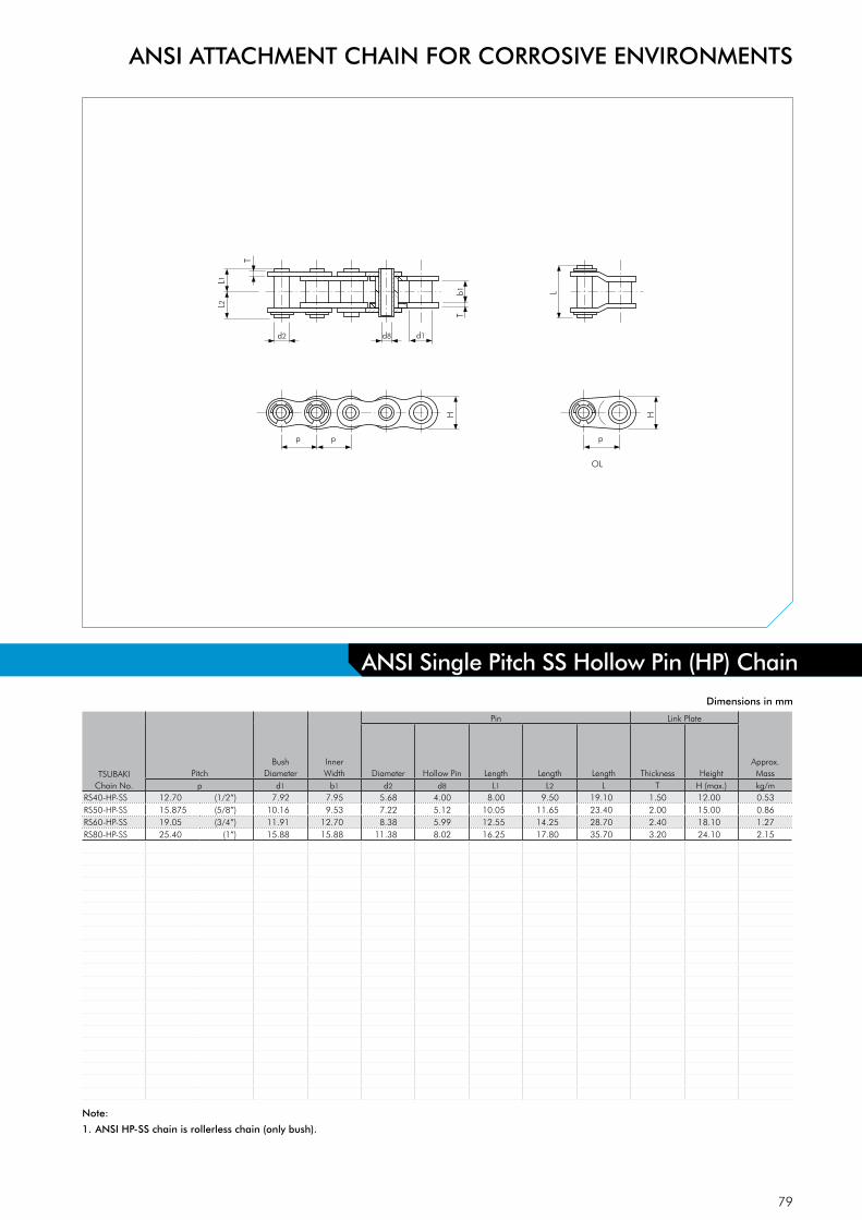
79
HHp
d1d2 d8
L1L2
T
b1
p p
OL
T
L
TSUBAKIChain No.
PitchBush
DiameterInner Width
Pin Link Plate
Approx. MassDiameter Hollow Pin Length Length Length Thickness Height
p d1 b1 d2 d8 L1 L2 L T H (max.) kg/mRS40-HP-SS 12.70 (1/2”) 7.92 7.95 5.68 4.00 8.00 9.50 19.10 1.50 12.00 0.53RS50-HP-SS 15.875 (5/8”) 10.16 9.53 7.22 5.12 10.05 11.65 23.40 2.00 15.00 0.86RS60-HP-SS 19.05 (3/4”) 11.91 12.70 8.38 5.99 12.55 14.25 28.70 2.40 18.10 1.27RS80-HP-SS 25.40 (1”) 15.88 15.88 11.38 8.02 16.25 17.80 35.70 3.20 24.10 2.15
Dimensions in mm
ANSI Single Pitch SS Hollow Pin (HP) Chain
ANSI ATTACHMENT CHAIN FOR CORROSIVE ENVIRONMENTS
Note:
1. ANSI HP-SS chain is rollerless chain (only bush).

80
L2L1
d2 d1
T
T
b1
X2C
N
X
S type roller OL OLR type roller
p
H
p
L2L1
d2 d4
T
T
b1
p
H
p
ST
S
T
ST
ST
p p
A-1 attachment(one side)
X2C
NK
X
p p
A-2 attachment(one side)
X2C
N
X
p p
K-1 attachment(both sides)
X2C
N
X
O
p p
K-2 attachment(both sides)
OOK
OXSC1
N O1 N
p p
SA-1 attachment(one side)
XSC3
p p
SA-2 attachment(one side)
XSC
1
N O1 N
p p
SK-1 attachment(both sides)
XSC
3
p p
SK-2 attachment(both sides)
D-1 attachment
L1L4
L3
d2
D-3 attachment
L1L4
L3
d2
p p
GK-1 attachment(both sides)
O2
KO
KO
L
p
L
p
TSUBAKIChain No.
PitchInner Width
Roller Pin Link PlateMax.
Allowable Load
acc. to Tsubaki
Approx. Mass
S Roller R Roller Diameter Length Length Length Length Length Thickness Height S Roller R Rollerp b1 d1 d4 d2 L1 L2 L3 L4 L T H kN kg/m kg/m
RF2040-SS 25.40 (1”) 7.95 7.92 15.88 3.97 8.25 9.95 9.50 16.75 18.60 1.50 12.00 0.44 0.51 0.87RF2050-SS 31.75 (1 1/4”) 9.53 10.16 19.05 5.09 10.30 12.00 11.90 21.00 23.90 2.00 15.00 0.69 0.84 1.30RF2060-SS 38.10 (1 1/2”) 12.70 11.91 22.23 5.96 14.55 16.55 14.30 27.45 32.80 3.20 17.20 1.03 1.51 2.19RF2080-SS 50.80 (2”) 15.88 15.88 28.58 7.94 18.30 20.90 19.10 35.50 42.10 4.00 23.00 1.76 2.41 3.52
TSUBAKIChain No.
Attachment DimensionsAttachment Mass
ASA
KSK
Ext.Pin
C C1 C3 K N O O1 O2 S X X2 XS kg/att. kg/att. kg/att.RF2040-SS 12.70 11.10 13.60 9.50 19.10 3.60 5.20 4.10 9.10 19.30 17.60 19.80 0.003 0.006 0.001RF2050-SS 15.90 14.30 15.90 11.90 23.80 5.20 6.80 5.10 11.10 24.20 22.00 24.60 0.006 0.012 0.002RF2060-SS 21.45 17.50 19.10 14.30 28.60 5.20 8.70 6.10 14.70 31.50 28.20 30.60 0.017 0.034 0.003RF2080-SS 27.80 22.20 25.40 19.10 38.10 6.80 10.30 8.10 19.10 40.70 36.60 40.50 0.032 0.064 0.007
Dimensions in mm
Note:
1. Connecting links are clip type for sizes up to RF2060-SS, and cotter type for RF2080-SS, all GK-1 attachments are cotter type.
2. R-Roller is not available with GK-1 attachment.
3. Special attachments are available on request.
4. Chain with S type roller is indicated as RF2040S-SS.
5. Chain with R type roller is indicated as RF2040R-SS.
ANSI Double Pitch SS Chain
ANSI ATTACHMENT CHAIN FOR CORROSIVE ENVIRONMENTS
Extended Pin Extended Pin

81
L
L2L1
d2 d8 d1
T
TT
b1
p
H
p p
L
L2L1
d2 d8 d4
T
b1p
H
p p
S type bush OL
OLR type roller
TSUBAKIChain No.
PitchInner Width S Bush R Roller
Pin Link Plate Approx. Mass
Diameter Hollow Pin Length Length Length Thickness Height S Bush R Rollerp b1 d1 d4 d2 d8 L1 L2 L T H kg/m kg/m
RF2040-HP-SS 25.40 (1”) 7.95 7.92 15.88 5.68 4.00 8.00 9.50 19.10 1.50 12.00 0.46 0.82RF2050-HP-SS 31.75 (1 1/4”) 9.53 10.16 19.05 7.22 5.12 10.05 11.65 23.40 2.00 15.00 0.75 1.21RF2060-HP-SS 38.10 (1 1/2”) 12.70 11.91 22.23 8.38 5.99 12.55 14.25 28.70 2.40 17.20 1.38 2.06RF2080-HP-SS 50.80 (2”) 15.88 15.88 28.58 11.38 8.02 16.25 17.80 35.70 3.20 23.00 1.80 2.81
Dimensions in mm
ANSI Double Pitch SS Hollow Pin (HP) Chain
ANSI ATTACHMENT CHAIN FOR CORROSIVE ENVIRONMENTS
Note:
1. Chain with S type bush is indicated as RF2040S-HP-SS.
2. Chain with R type roller is indicated as RF2040R-HP-SS.

82
STOCK SPECIALTY ATTACHMENT CHAIN
Fig. 27 RS60-2 AS Special Fig. 28 RS35 and RS40 Special WA
Fig. 29 RS12B Special Extended Pin
Can Processing Industry Packaging Industry
Book Binding Industry
Fig. 30 RS08B and RS10B Gripper Chain
Fig. 31 RS50 and RF2050 Special Extended Pin Fig. 32 RF2030 VRP to RF2080 VRP Double Plus Chain
Packaging Industry
Automotive and Electronics IndustryPackaging Industry

83
TSUBAKI ATTACHMENT CHAIN APPLICATION CHECK SHEET
Please complete and return to Tsubakimoto Europe B.V. on fax: +31-(0)78 6204001
Date:
Company name: Tel:
Contact person: Fax:
1) Type of requirement o New design o Replacement o Investigation
If replacement - Motor size (kW)
Sprocket size (Teeth)
2) Type of conveyor o Slat conveyor o Bucket conveyor
o Pusher o Other
3) Mass & quantity of slats, pushers etc.: (kg/pc) (pc)
4) Conveying direction: o Horizontal o Vertical
Inclined - Specify Gradient
5) Description of conveyed goods:
6) Length of conveying portion: (m)
7) Mass of conveyed goods in conveying portion: (kg/pc)
8) Maximum quantity of conveyed goods:
in conveying portion: (pc)
9) Length of accumulated portion (if where): (m)
10) Mass of conveyed goods in accumulated portion: (kg/pc)
11) Maximum quantity of conveyed goods
in accumulated portion: (pc)
12) Size of conveyed goods Length (mm)
Width (mm)
Height (mm)
13) Conveying speed: (m/min.)
14) For indexing applications Mass (or size) of driven sprocket kg (teeth)
Acceleration and deceleration (m/sec2)
Feed per index (m)
Time to complete index (second)
Cam curve o Modified sin curve (MS)
o Modified trapezoidal curve (MT)
o Modified sin mean curve (MSC)
15) Desired chain pitch: (mm)
16) Desired attachment type and spacing:
17) Number of chain strands: (strand)
18) Lubrication condition o With lubrication o Without lubrication
19) Operation time: hours per day days per week weeks per year
20) Temperature: (°C)
21) Environmental conditions (corrosive, humid etc.):

84
TSUBAKI ATTACHMENT CHAIN LAYOUT SHEET
Tsubakimoto Europe B.V.
Aventurijn 12003316 LB DordrechtThe Netherlands
FAX: +31 (0)78-6204001E-MAIL: [email protected]
Customer Name:
Contact:
Chain type:
Chain length:
Total no. of attachments:
EASY SPACING GUIDE FOR ATTACHMENT CHAINS
20
40
60
80
100

85
TEMPERATURE SELECTION METHOD
This selection method is for chains that may experience strength degradation from temperature. Additionally, lubrication should be carried out using a suitable lubricant according to the opera-ting temperatures.
High TemperatureWhen chains are used in high temperatures, the following problems may occur:• Increased wear due to decreased hardness. • Poor articulation and increased wear due to lubricant dete-
rioration and carbonization. • Stiff joints and increased wear due to oxide scale formation. • Increased elongation due to softening.• Decreased strength.
To prevent lubricant deterioration at high temperatures, use a special lubricant.
When chains are used in temperatures above +250°C, pay special attention to the composition and heat-treatment of the chain. The most popular type of chain for high temperature is SS speci-fication, which is made of 304 equivalent stainless steel and has a maximum working temperature of +650°C at low speeds. Ho-wever, to maintain an adequate safety margin at a high tempe-rature like this, we suggest NS specification chain. NS chain is made of 316 stainless steel, which contains molybdenum and less carbon. NS specification has worked at low speed in environments up to +700°C.
If your operation runs at temperatures higher than +400°C, consult Tsubaki before making your chain selection. Production methods and materials may be specially adapted for your application.
Low TemperatureWhen chains are used in low temperatures, the following problems may occur:• Decreased shock strength due to low-temperature brittleness. • Lubricant solidification. • Stiff joints caused by frost or ice adhesion.
Two types of chain are especially useful at lower temperatures. KT specification chain is specially heat-treated to withstand very cold environments. SS specification chain, which is made of 304 equivalent stainless steel, may also be used at low temperatures. Low-temperature brittleness does not occur in austenitic stainless steel.These chains cannot fix the problems of solidification of the lubri-cant or stiff joints caused by frost or ice. Use cold-temperature oil or grease and apply it to the inner clearances and the outside of the chain.
Standard engineered plastic chain can be run at temperatures between -20°C and +80°C. At higher temperatures, it may become soft and not keep its shape; at lower temperatures it may become brittle.
Below -60°C - - unusable -
-60°C to -50°C - - MAL / 2 -
-50°C to -40°C - unusable MAL / 1.5 -
-40°C to -30°C unusable MAL / 4 MAL -
-30°C to -20°C MAL / 4 MAL / 3 MAL #
-20°C to -10°C MAL / 3 MAL / 2 MAL MAL
-10°C to +60°C MAL MAL MAL MAL
+60°C to +150°C MAL MAL unusable MAL
+150°C to +200°C MAL / 1.3 MAL / 1.3 - MAL
+200°C to +250°C MAL / 2 MAL / 2 - MAL
+250°C to +400°C unusable unusable - MAL
+400°C to +500°C - - - #
+500°C to +600°C - - - -
+600°C to +700°C - - - -
above +700°C - - - -Notes:
* KT Cold Resistant Chain: Made to order.
The ambient temperature is different from the temperature of the roller chain itself.
MAL = Maximum Allowable Load. For details contact Tsubaki.
# Please consult TSUBAKI for more detailed information.
KT Cold Resistant Temperature upto 1” pitch 1” pitch and over Chain* SS, NS, AS Chain
Standard Roller Chain
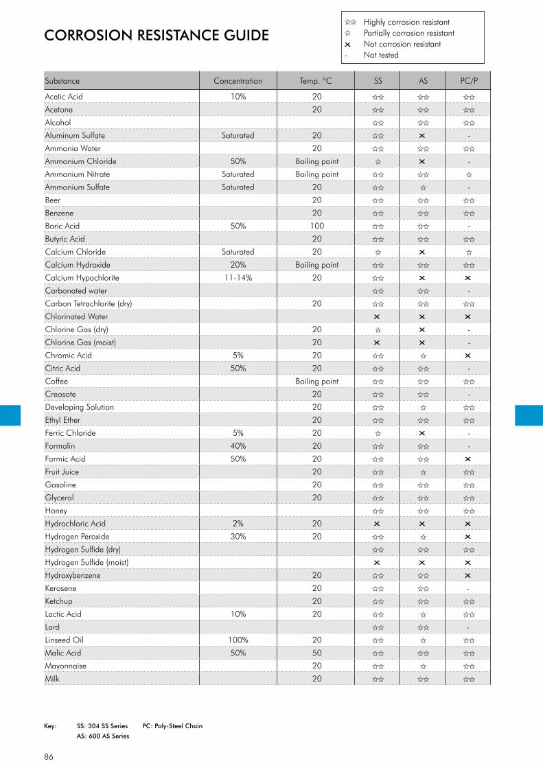
86
Substance Concen tration Temp. ºC SS AS PC/P
Acetic Acid 10% 20
Acetone 20
Alcohol
Aluminum Sulfate Saturated 20 x -
Ammonia Water 20
Ammonium Chloride 50% Boiling point x -
Ammonium Nitrate Saturated Boiling point
Ammonium Sulfate Saturated 20 -
Beer 20
Benzene 20
Boric Acid 50% 100 -
Butyric Acid 20
Calcium Chloride Saturated 20 x
Calcium Hydroxide 20% Boiling point
Calcium Hypochlorite 11-14% 20 x x
Carbonated water -
Carbon Tetrachlorite (dry) 20
Chlorinated Water x x x
Chlorine Gas (dry) 20 x -
Chlorine Gas (moist) 20 x x -
Chromic Acid 5% 20 x
Citric Acid 50% 20 -
Coffee Boiling point
Creosote 20 -
Developing Solution 20
Ethyl Ether 20
Ferric Chloride 5% 20 x -
Formalin 40% 20 -
Formic Acid 50% 20 x
Fruit Juice 20
Gasoline 20
Glycerol 20
Honey
Hydrochloric Acid 2% 20 x x x
Hydrogen Peroxide 30% 20 x
Hydrogen Sulfide (dry)
Hydrogen Sulfide (moist) x x x
Hydroxybenzene 20 x
Kerosene 20 -
Ketchup 20
Lactic Acid 10% 20
Lard -
Linseed Oil 100% 20
Malic Acid 50% 50
Mayonnaise 20
Milk 20
CORROSION RESISTANCE GUIDE Highly corrosion resistant
Partially corrosion resistant x Not corrosion resistant- Not tested
Key: SS: 304 SS Series PC: Poly-Steel Chain
AS: 600 AS Series

87
Substance Concen tration Temp. ºC SS AS PC/P
Nitric Acid 5% 20 x
Nitric Acid 65% 20 x x
Nitric Acid 65% Boiling point x x
Oil (Plant, Mineral) 20
Oleic Acid 20
Oxalic Acid 10% 20 -
Paraffin 20
Petroleum 20
Phosphoric Acid 5% 20 x
Phosphoric Acid 10% 20 x
Picric Acid Saturated 20 -
Potassium Bichromate 10% 20
Potassium Chloride Saturated 20 -
Potassium Hydroxide 20% 20
Potassium Nitrate 25% 20
Potassium Nitrate 25% Boiling point x -
Potassium Permanganate Saturated 20 -
Sea-Water 20 x
Soap-and-Water-Solution 20
Sodium Carbonate Saturated Boiling point -
Sodium Chloride 5% 20
Sodium Cyanide 20 - -
Sodium Hydrocarbonate 20
Sodium Hydroxide 25% 20
Sodium Hypochlorite 10% 20 x x x
Sodium Perchlorate 10% Boiling point x -
Sodium Sulfate Saturated 20 -
Sodium Thiosulfate 25% Boiling point -
Soft Drink 20
Stearic Acid 100% Boiling point x x x
Sugar Solution 20
Sulfuric Acid 5% 20 x x x
Sulfur Dioxide (moist) 20 x -
Synthetic Detergent
Syrup
Tartaric Acid 10% 20
Turpentine 35 -
Varnish -
Vegetable Juice 20
Vinegar 20
Water
Whiskey 20
Wine 20
Zinc Chloride 50% 20 x
Zinc Sulfate Saturated 20 -
Wine 20
Zinc Chloride 50% 20 -
Zinc Sulfate 25% 20 x
CORROSION RESISTANCE GUIDE
This table is intended only as a guide and TSUBAKI does not take responsibility for mishaps arising from its use.
88
1. General In these general terms and conditions ‘Tsubaki’ shall mean Tsubakimoto Europe B.V.
2. Applicability2.1 The applicability of the general terms and conditions used by the customer is hereby
expressly excluded.2.2 These general terms and conditions are applicable to all legal relationships in which
Tsubaki acts as a seller and/or supplier or as a potential seller and/or supplier of products and/or services.
2.3 Deviations from the provisions in these general terms and conditions shall be permitted only in writing. No rights in relation to agreements that are concluded later may be derived from such deviations.
3. Conclusion of the agreement / Measurements & Weight3.1 If the customer issues an order, the agreement shall have been concluded if Tsubaki
accepts the order in writing or electronically or makes a start with its implementation.3.2 Drawings, measurements and weights that are shown or provided on the website of
Tsubaki or otherwise, shall only be used as indications. The product and/or service to be provided under the agreement need not correspond with the drawing, measurement and weight.
4. Prices / Delivery conditions4.1 Prices are exclusive of VAT.4.2 Prices are ex warehouse, unless otherwise agreed in writing.4.3 Prices are as per Tsubaki described standard unit or packaging only.4.4 In addition to the price, the customer shall fully pay, unless otherwise agreed in writing,
any and all, local taxes, duties, excises, licence fees and other charges levied, assessed or imposed upon Tsubaki due to the manufacture, sale, purchase, export or delivery of the products.
4.5 The customer shall also pay the cost by which such manufacture is increased by reason of any law, ordinance or regulation adopted or promulgated by any government or go-vernmental subdivision, department or agency, or other source, after the date hereof, but prior to the completion and delivery hereunder.
4.6 Changes in labour costs, cost prices of raw materials or materials and/or exchange rate movements related to the performance agreed on, shall entitle Tsubaki to pass on these costs to the customer.
5. Delivery/delivery times5.1 The delivery period indicated by Tsubaki starts as from the moment that all data, drawings
and the like necessary for the performance of the agreement have been received by Tsubaki in its entirety.
5.2 Delivery times agreed with Tsubaki are indicative and shall not constitute deadlines.5.3 Failure to deliver within the indicated delivery period does not entitle the customer to
additional or substitute damages, nor to the customer’s non-fulfilment, withholding or postponement of any of its own obligations arising from the agreement.
5.4 If the customer requests Tsubaki to make changes in the performance of the agreement (including, but not limited to, changes in the design or construction of products), or otherwise delay or interrupt the progress of the work under the agreement, the customer shall fully reimburse Tsubaki for any and all additional expenses arising there from.
5.5 Tsubaki shall be entitled to perform its due obligation(s) in stages or in parts. Each partial delivery shall be deemed an independent delivery with respect to the applicability of these general terms and conditions.
6. Returned products6.1 No products shall be acceptable for return without prior written consent of Tsubaki.6.2 Special or made-to-order products are not returnable.6.3 The customer shall prepay freight on all returns, and each return is subject to inspection
and acceptance by Tsubaki to assure that the products are in a “re-sellable” condition.6.4 The customer shall pay a maximum of 10% (ten percent) of the price for handling and
restocking costs charge with regard to all authorized returns.
7. Payment 7.1 Payment of Tsubaki’s invoices shall ultimately take place within 30 (thirty) days after the
invoice date in the manner described by Tsubaki, provided however that Tsubaki may at all times request for payment in advance. Payment shall take place effectively in the cur-rency agreed on and without deduction, set-of, discount and/or deferment.
7.2 In case of overdue payment, all payment obligations of the customer, regardless of whether Tsubaki has already issued an invoice in the matter and of whether Tsubaki has duly performed its obligations, shall be immediately due and payable and the customer shall owe an interest of 1.5% (one and a half percent) per month or per part of a month on the amount due.
7.3 Extra-judicial collection costs shall be charged to the customer in accordance with the collection rates of the Netherlands Bar Association.
7.4 Payment by or on behalf of the customer shall extend to payment of the following charges incurred, in the following order: extra-judicial collection costs, the legal costs, the interest due, and after that the unpaid capital sums according to the order of receipt, regardless of other instructions of the customer.
7.5 The customer can only object to the invoice within the term of payment.
8. Intellectual Property Rights and know-how8.1 All documentation, sales leaflets, pictures, drawings etc., provided by Tsubaki to the cus-
tomer, shall at all times remain the exclusive property of Tsubaki.8.2 The customer shall not be entitled to use the documents referred to in paragraph 1 for
any purpose other than for the use of the products to which they relate.8.3 The customer shall not be entitled to use the documents referred to in paragraph 1 or to
duplicate and/or make public to third parties data included therein or in any other way made known to the customer without express prior written consent of Tsubaki.
8.4 In the event of any violation of what has been stipulated under paragraph 2 and/or 3, the customer shall pay Tsubaki an immediately payable fine of EUR 10,000 (ten thousand euros) for each violation, regardless of any other of Tsubaki’s rights to performance, dis-solution, compensation, etc.
9. Retention of title9.1 All products that are delivered or are to be delivered by Tsubaki remain the property of
Tsubaki until Tsubaki is fully paid with regard to: A. all performances due by the customer for all products that are delivered or are to
be delivered in accordance with the agreement, and; B. all claims that are the result of the customer’s failing in the performance of such
agreement(s); the customer shall not be allowed to claim its right of retention concerning costs of custody and to deduct these costs with the performances re-quired by the customer.
9.2 If the customer creates a new product from or partly from products referred to in paragraph 1, this product belongs to Tsubaki and the customer shall consider Tsubaki its owner, until the customer has fully performed all of its obligations referred to in paragraph 1.
9.3 If any product belongs to Tsubaki in accordance with paragraph 1 and/or 2, the customer can have exclusive possession of this product or product within the framework of its nor-mal business operations.
9.4 If the customer is in default in the performance of its obligations referred to in paragraph 1, Tsubaki shall be entitled to recover all the products from their location, at the expense of the customer. The customer hereby irrevocably grants authority to Tsubaki to enter the area used by or for the customer.
10. Security10.1 If there are valid grounds to expect that the customer shall not perform its obligations, the
customer shall be obliged, at the first request of Tsubaki, to immediately furnish adequate security in the form requested by Tsubaki (including complete payment in cash before or on delivery) without prejudice to customer’s obligations under the agreement. If and to the extent that the customer has not fully performed its obligations, Tsubaki shall be entit-led to suspend performance of its obligations.
10.2 If the customer takes no action on the request referred to in paragraph 1 within 14 (fourteen) days after having received a written warning to that effect, all its obligations shall be immediately due and payable.
11. Guarantee11.1 With regard to the assembly carried out by Tsubaki, the following guarantee is provided:
For 6 (six) months, Tsubaki shall repair faults in the assembly, free of charge, at the dis-cretion of Tsubaki.
11.2 If and to the extent Tsubaki can claim guarantee with respect to its own suppliers, Tsubaki shall provide the following guarantee on products obtained from them: For 6 (six) months, Tsubaki shall supply alternative products, free of charge, if the products supplied exhibit manufacturing defects or defects in the material, at the discretion of Tsubaki.
11.3 The customer can only make a non-recurring claim under the guarantee mentioned in paragraphs 1 and 2 if the customer has performed all its obligations towards Tsubaki.
11.4 Defects which are the result of normal wear, improper use or improper or incorrect main-tenance or which occur after changes or repair carried out by or on behalf of the custo-mer, shall not be part of the guarantee.
11.5 Minor differences, which means 10% (ten percent) or less with regard to amounts, measu-res, weights, numbers and other such data provided, are not considered defects.
12. Complaints / obligation to examine / limitation period12.1 On delivery, the customer has the obligation to examine whether the products are in
conformity with the agreement. If this is not the case, the customer cannot make a claim regarding non-conformity if the customer does not notify Tsubaki in writing in a well-founded manner as soon as possible, but in any event within 8 (eight) days after delivery or after detection of non-conformity was reasonably possible.
12.2 Any and all of the customer’s claims and defences based on facts that support the view that the product delivered is not in conformity with the agreement, shall expire 6 (six) months after delivery.
13. Dissolution and release13.1 If the customer does not perform or incorrectly performs any of its obligations arising from
the agreement (such as overdue payment), if the customer is placed under guardianship, involuntary liquidation, suspension of payment or closure or winding up of its company, and also in the case of prejudgment or executory attachment against the customer or if an offer or agreement with regard to an extra-judicial debt settlement with the customer has been made, Tsubaki shall be entitled, at its option, without any obligation for com-pensation and without prejudice to its other rights, to dissolve the agreement in whole or in part, or to suspend the further execution of the agreement. In these cases, Tsubaki shall be also entitled to claim immediate compensation of the amount due.
13.2 If the proper performance by Tsubaki is partially or completely impossible, whether tem-porarily or permanently, due to one or more circumstances which cannot be held ac-countable to Tsubaki, including the circumstances mentioned in the paragraph 14.6, Tsubaki, at its option, shall be entitled to suspend its performance or to dissolve the agreement.
13.3 If the customer is not willing to cooperate with the delivery after Tsubaki has given the customer 14 (fourteen) days to do so, Tsubaki will be released from its obligations, wit-hout prejudice to the obligations of the customer.
14. Compensation14.1 Tsubaki shall only be liable for damages suffered by the customer which can be attributed
to gross negligence or intention by Tsubaki to the amount that Tsubaki is insured in ac-cordance with an insurance commonly used in this line of industry and which is actually paid out with respect thereto. The aggregate compensation payable by Tsubaki shall not exceed EUR 500.000 (five hundred thousand euros) per event, whereby a series of rela-ted events shall be considered as one event.
GENERAL TERMS AND CONDITIONS OF SALE TSUBAKIMOTO EUROPE B.V.

89
GENERAL TERMS AND CONDITIONS OF SALE TSUBAKIMOTO EUROPE B.V.
14.2 Tsubaki shall never be liable to pay any compensation other than personal injury or pro-perty damage.
14.3 Tsubaki shall never be liable for loss of income, profit or revenue, loss due to shutdown or delay in business activities, production losses, loss of operating hours and/or wages paid in vain, extra costs incurred due to external purchasing, loss due to restoration of lost information, missed savings or agreements, discounts or penalties.
14.4 Tsubaki stipulates all legal and contractual defences, which it can invoke to fend off its own liability towards the customer, also on behalf of its employees and non-employees for whose acts it is liable in accordance with the law.
14.5 Tsubaki shall not be liable with regard to products supplied by Tsubaki which originate from third parties if and to the extent that the applicable third party has excluded its liability.
14.6 Under no circumstance shall Tsubaki be held liable for the following circumstances: actions, except gross negligence or intention, of persons used by Tsubaki for the realisation of the agreement; unsuitability of products which Tsubaki uses for the realisation of the agree-ment; exercising one or more rights by a third party vis-à-vis the customer in the case of a failure in the performance by the customer of an agreement between the customer and the third party concerning products supplied by Tsubaki; industrial action, lockout of workers, illness, bans on import, export and/or transport, problems with transport, failure to comply with the obligations by suppliers, production failure, natural and/or nuclear disasters, and war and/or threat of war.
14.7 The customer shall indemnify Tsubaki against all claims from any third party, in whatever form, with regard to damage and/or loss, which any third party may have suffered due to products of Tsubaki.
14.8 Everything stipulated in this article shall be without prejudice to Tsubaki’s liability pursuant to mandatory provisions of law.
15. Amendment of general terms and conditions15.1 Tsubaki has the right to amend these general terms and conditions from time to time.
Amendments apply also with regard to agreements already concluded. Amendments shall be notified in advance in writing or electronically to the customer and shall enter into effect 30 (thirty) days after this notification or on such date as specified in the notification.
15.2 In the event the customer fails, with respect to the amended general terms and conditions, to give written notice that it does not accept these amended general terms and conditions prior to the day on which the aforementioned terms enter into effect, such as is indicated
here above, the customer shall be deemed to have accepted these amended general terms and conditions.
16. Conversion If and to the extent that any provision in these general terms and conditions cannot be
invoked on grounds of reasonableness and fairness or its unreasonably onerous nature, the provision shall be given a meaning that corresponds as much as possible to its con-tent and purpose, making it thereby possible to invoke this provision.
17. Assignment17.1 Tsubaki is entitled to assign one or more of its obligations or its entire legal relationship
with the customer to a third party without consent of the customer. Tsubaki shall inform the customer of this transfer in writing.
17.2 The customer is only entitled to assign one or more of its obligations or its entire legal relationship with Tsubaki to a third party upon Tsubaki’s express prior written consent.
18. Applicable law / competent court18.1 All legal relationships between Tsubaki and the customer shall be governed by the laws of
the Netherlands, without taking into account the principles of conflict of laws.18.2 The applicability of the United Nations Convention on Contracts for the International Sale
of Goods is expressly excluded.18.3 All disputes which may arise between Tsubaki and the customer that fall under the juris-
diction of a district court, shall only be submitted to the court in the judicial district in which Tsubaki has its registered office, unless Tsubaki as a plaintiff or an applicant opts for the competent court in which the customer has its registered office or address for service.
19. Dutch text prevails If and insofar as there is a discrepancy between the general terms and conditions in the
Dutch language and those in the English language, those in the Dutch language shall prevail.
These conditions were filed at the Chamber of Commerce and Industry in Rotterdam.
WARNING Obey the following points in order to prevent hazardous situations.• Do not use chains and accessories (accessories and parts) for anything other than their orginal purpose.• Never perform additional processing on the chain: - Do not anneal the various parts of the chain. - Do not clean the chain with either acid or alkali, as they may cause cracking. - Do not electroplate the chain or its parts, as they may cause cracking due to hydrogen embrittlement. - Do not weld the chain, as the heat may cause cracking or a reduction in strength. - When heating or cutting the chain with a torch, remove the links immediately adjacent and do not use them again.• When there is need to replace a lost or damaged portion of a chain, always replace the whole chain with a new product rather
than replacing only the lost or damaged portion.• When using a chain on suspension equipment, establish a safety manual, etc., and strictly prevent entry to the area directly
below the suspended object.• Always employ hazard protector devices for the chain and sprocket (safety cover, etc.).• If a substance that can cause embrittlement cracking (acid, strong alkali, battery fluid, etc.) adheres to the chain, stop using
the chain immediately and replace it with a new one.• During installation, removal, maintenance inspection and lubrication of the chain: - Perform the operation according to the instruction manual or this catalog. - Always turn off the power switch to the device and make sure that it cannot be turned on accidentally. - Anchor the chain and parts so that they cannot move freely. - Perform cutting and connecting procedures properly using a press or other special tool. - Wear clothing and employ protective devices that are appropriate to the job (safety glasses, gloves, safety shoes, etc.). - Only allow experienced personnel to perform chain replacement procedures.• In order to prevent hazards, damage, or injury when cutting a Leaf Chain, always install hazard protection devices (safety
device, etc.) on the suspension equipment employing the Leaf Chain.
CAUTION Obey the following points in order to prevent accident.• Only handle the chain after thoroughly understanding its structure and specifications.• When installing a chain, inspect it in advance to confirm that is has not been damaged in transport.• Be sure to perform regular maintenance inspections on the chain and sprocket.• Chain strength varies according to manufacturer. When selecting a chain based on a Tsubaki catalog, always use the cor-
responding Tsubaki product.• Minimum tensile strength refers to the failure point when the corresponding load is applied to the chain once and does not
refer to the allowable operational load.
For Safe Use

90
TEU Cat 1-2, 2015
NOTE: in accordance with the policy of Tsubakimoto Europe B.V. to consistently improve its products, the specifications in this
catalogue are subject to change without notice.
Copyright © 2015 Tsubakimoto Europe B.V.
The contents of this catalogue must not be reproduced in any way unless written permission is obtained.
Every care has been taken to ensure the accuracy of the information in this catalogue but no responsibility or liability can be
accepted for any loss or damage suffered as a result of information it contains.
The catalogue information is subject to change without notice so please do not hesitate to contact Tsubakimoto Europe if you need clarification or have any queries.
DISTRIBUTED BY:

DRIVE C
HA
IN / ATTAC
HM
ENT C
HA
INC
ATALO
GU
E 1-2
Tsubakimoto Europe B.V.
Aventurijn 12003316 LB DordrechtThe Netherlands
Phone: +31 (0)78 620 4000Fax: +31 (0)78 620 4001E-mail: [email protected]: tsubaki.eu
Tsubakimoto Deutschland GmbH
ASTO Park OberpfaffenhofenFriedrichshafener Straße 1D-82205 Gilching, Germany
Phone: +49 (0)8105 7307 100Fax: +49 (0)8105 7307 101E-mail: [email protected]: tsubaki.de
Tsubakimoto UK Ltd.
Osier Drive, Sherwood ParkAnnesley, Nottingham NG15 0DXUnited Kingdom
Phone: +44 (0)1623 68 87 00Fax: +44 (0)1623 68 87 89E-mail: [email protected]: tsubaki.eu


