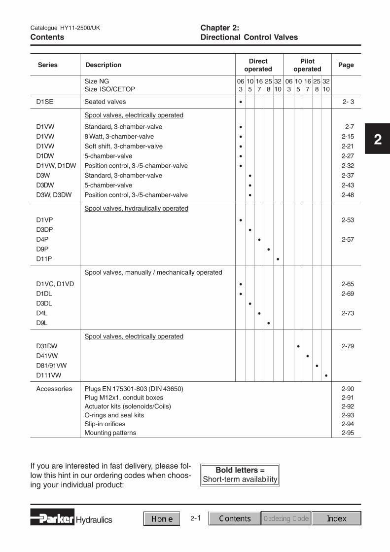
If you are interested in fast delivery, please fol-low this hint in our ordering codes when choos-ing your individual product:
2-2
D1SE_GB.PM6.5MM
Hydraulics
3/2-Way Seated Type Directional Control ValveSeries D1SE
Catalogue HY11-2500/UK
2
Notes
2-3
2
D1SE_GB.PM6.5MM
Hydraulics
3/2-Way Seated Type Directional Control ValveSeries D1SE
Catalogue HY11-2500/UK
2
Characteristics
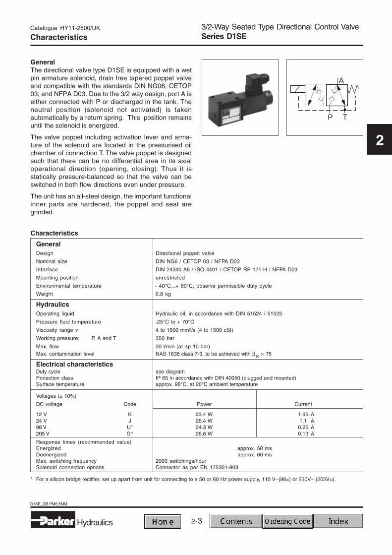
GeneralThe directional valve type D1SE is equipped with a wetpin armature solenoid, drain free tapered poppet valveand compatible with the standards DIN NG06, CETOP03, and NFPA D03. Due to the 3/2 way design, port A iseither connected with P or discharged in the tank. Theneutral position (solenoid not activated) is takenautomatically by a return spring. This position remainsuntil the solenoid is energized.
The valve poppet including activation lever and arma-ture of the solenoid are located in the pressurised oilchamber of connection T. The valve poppet is designedsuch that there can be no differential area in its axialoperational direction (opening, closing). Thus it isstatically pressure-balanced so that the valve can beswitched in both flow directions even under pressure.
The unit has an all-steel design, the important functionalinner parts are hardened, the poppet and seat aregrinded.
Characteristics
GeneralDesign Directional poppet valve
Nominal size DIN NG6 / CETOP 03 / NFPA D03
Interface DIN 24340 A6 / ISO 4401 / CETOP RP 121-H / NFPA D03
Mounting position unrestricted
Environmental temperature - 40°C...+ 80°C, observe permissible duty cycle
Weight 0.8 kg
HydraulicsOperating liquid Hydraulic oil, in accordance with DIN 51524 / 51525
Pressure fluid temperature -25°C to + 70°C
Viscosity range ν 4 to 1500 mm2/s (4 to 1500 cSt)
Working pressure: P, A and T 350 bar
Max. flow 20 l/min (at ∆p 10 bar)Max. contamination level NAS 1638 class 7-9, to be achieved with β10 > 75
Electrical characteristicsDuty cycle see diagramProtection class IP 65 in accordance with DIN 40050 (plugged and mounted)Surface temperature approx. 98°C, at 20°C ambient temperature
Voltages (± 10%)
DC voltage Code Power Current
12 V K 23.4 W 1.95 A24 V J 26.4 W 1.1 A98 V U* 24.3 W 0.25 A205 V G* 26.6 W 0.13 A
Response times (recommended value)Energized approx. 50 msDeenergized approx. 60 msMax. switching frequency 2000 switchings/hourSolenoid connection options Connector as per EN 175301-803
* For a silicon bridge rectifier, set up apart from unit for connecting to a 50 or 60 Hz power supply, 110 V~(98=) or 230V~ (205V=).
2-4
D1SE_GB.PM6.5MM
Hydraulics
3/2-Way Seated Type Directional Control ValveSeries D1SE
Catalogue HY11-2500/UK
2
Ordering Code
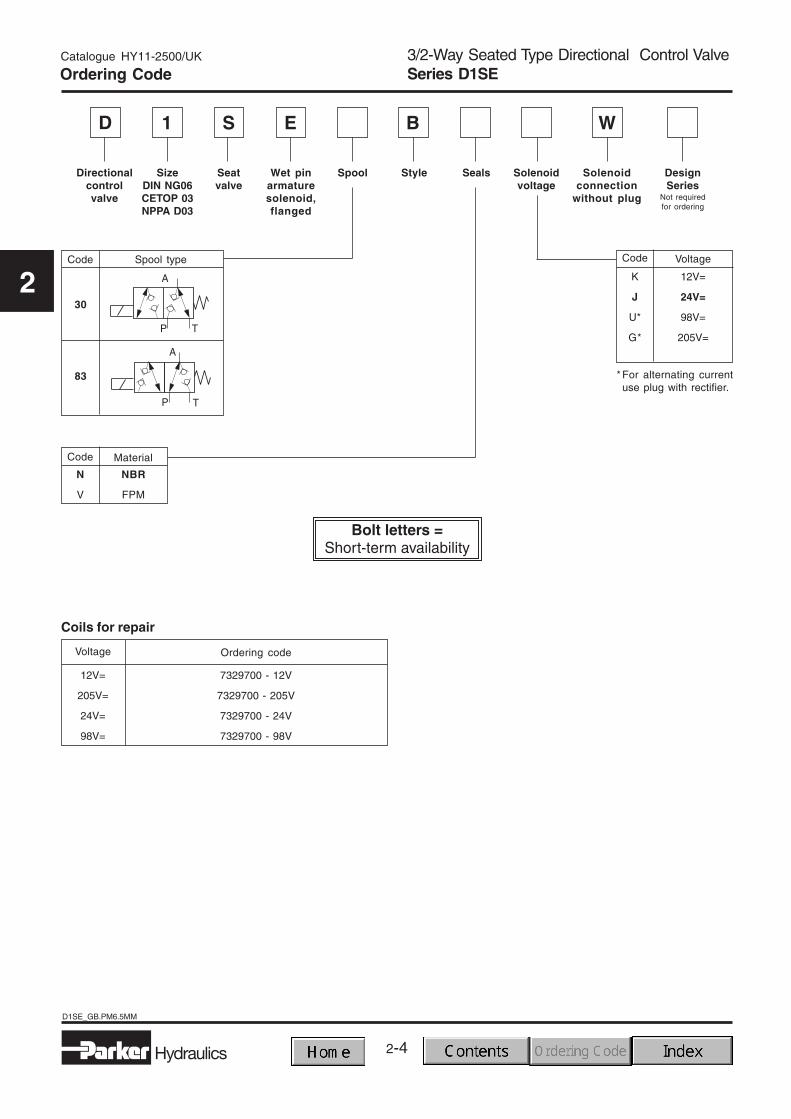
D S E1
Code
K
J
U*
G*
Voltage
12V=
24V=
98V=
205V=
Code Material
NBR
FPM
N
V
Spool typeCode
30
83 * For alternating currentuse plug with rectifier.
B
Directionalcontrolvalve
Seatvalve
Wet pinarmaturesolenoid,flanged
SizeDIN NG06CETOP 03NPPA D03
DesignSeries
Not requiredfor ordering
Style Solenoidvoltage
Seals Solenoidconnection
without plug
Spool
A
P T
Voltage
12V=
205V=
24V=
98V=
Ordering code
7329700 - 12V
7329700 - 205V
7329700 - 24V
7329700 - 98V
Coils for repair
W
2-5
2
D1SE_GB.PM6.5MM
Hydraulics
3/2-Way Seated Type Directional Control ValveSeries D1SE
Catalogue HY11-2500/UK
2
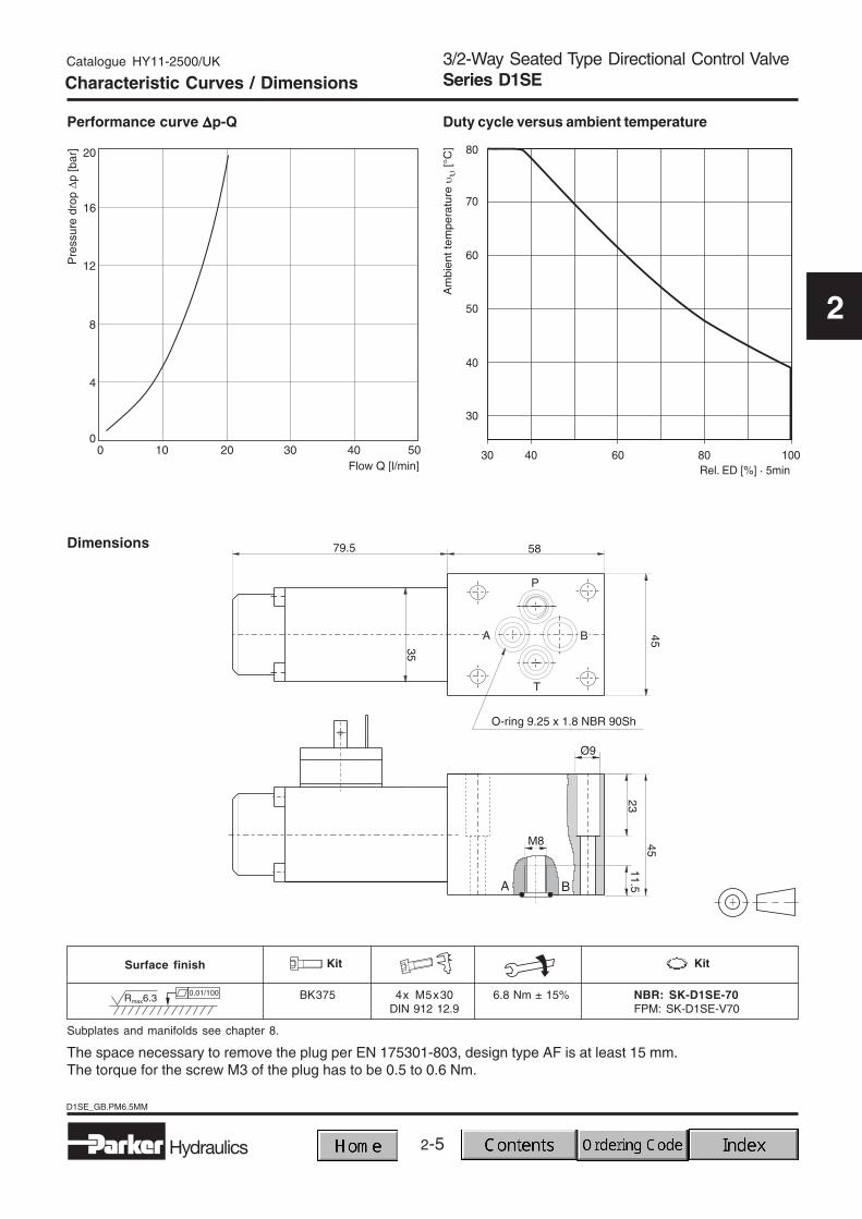
Characteristic Curves / Dimensions
Dimensions
Performance curve ∆∆∆∆∆p-Q Duty cycle versus ambient temperature
The space necessary to remove the plug per EN 175301-803, design type AF is at least 15 mm.The torque for the screw M3 of the plug has to be 0.5 to 0.6 Nm.
2-6
D1VW-St_GB.PM6.5MM
Hydraulics
Catalogue HY11-2500/UK
2
Notes
2-7
2
Hydraulics
D1VW-St_GB.PM6.5MM
Catalogue HY11-2500/UK
2
Characteristics
GeneralDesign Directional spool valveSize DIN NG6 / CETOP 03 / NFPA D03Interface DIN 24340 A6 / ISO 4401 / CETOP RP 121-H / NFPA D03Mounting position unrestricted, preferably horizontalEnvironmental temperature -25°C...+50°CWeight: Valve with 1 solenoid 1.5 kg
Valve with 2 solenoids 2.1 kg
HydraulicsFluids Hydraulic oil, in accordance with DIN 51524 / 51525Fluid temperature -25°C to + 70°CViscosity range ν 2.8 to 400 mm2/s (2.8 to 400 cSt)Working pressure: P, A and B 350 bar
T DC: 210 bar AC: Standard: 105 bar Code “H”: 210 barLeakage: ∆p = 50 bar; ν = 35 mm2/s up to 10 ml/min per flow path, depending on spoolMax. flow 80 l/minMax. contamination level NAS 1638 class 7-9, to be achieved with β10 > 75
Electrical characteristicsDuty cycle 100% ED; CAUTION: Coil temperature up to 150º C possible
Protection class IP 65 in accordance with DIN 40050 (plugged and mounted)Voltages (±10%) Holding in Rush
DC voltage Code Power Current Power Current
12 V K 30 W 2.5 A - -24 V J 30 W 1.25 A - -98 V U 30 W 0.31 A - -205 V G 30 W 0.15 A - -AC voltage110V 50 Hz / 120V 60 Hz Y 64 VA / 59 VA 0.58 A / 0.49 A 231 VA / 240 VA 2.1 A / 2.0 A230V 50 Hz / 240 V 60 Hz T 68 VA / 62 VA 0.31 A / 0.26 A 231 VA / 240 VA 1.05 A / 1.0 AResponse times (at 32 l/min and 250 bar) DC voltage AC voltageEnergized / deenergized 32 ms / 40 ms 13 ms / 20 ms
Max. switching frequency 15000 switchings/hour
Solenoid connection options Connector as per EN 175301-803, solenoid identification according to ISO 9461.Conduit box with flying leads, optional with Brad Harrison plug.
Directional Control ValvesSeries D1VWCharacteristics
The D1VW is a 3 chamber-, electrically controlled 4/3or 4/2 way directional control valve. It is activated di-rectly by solenoids with screwed in wet pin armature.The coils can be exchanged for various input voltages,however, a change between alternating (AC) and directcurrent (DC) is not possible.
2-8
D1VW-St_GB.PM6.5MM
Hydraulics
Catalogue HY11-2500/UK
2
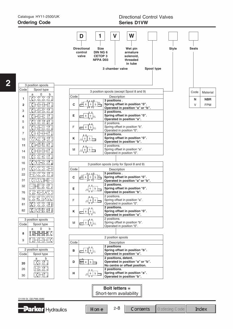
Directional Control ValvesSeries D1VWOrdering Code
WD V
Directionalcontrolvalve
Wet pinarmaturesolenoid,threadedin tube
3 chamber valve
Seals
Code
N NBR
V FPM
Material
Style
Spool type
1
SizeDIN NG 6CETOP 3
NFPA D03
2-9
2
Hydraulics
D1VW-St_GB.PM6.5MM
Catalogue HY11-2500/UK
2
Directional Control ValvesSeries D1VW
Solenoidoptions
Solenoidconnection
Designseries
Not requiredfor ordering
Solenoidvoltage
Accessories
Further spool types, styles, voltages, accessories andcombinations on request.
Code Voltage
110V 50Hz120V 60Hz
230V 50Hz240V 60Hz
Y
T
2) For alternating currentuse plug with rectifier,and order with solenoidconnection code W.Please order rectifierplug separately.
Code Description
2) Please order plug separately.See chapter 2. accessories.
Conduit box withflying leads
C
Connector asper EN 175301-803,
without plugW 2)
12V=
24V=
98V=
205V=
K
J
U 2)
G 2)
Code Description
omit Standard valvewithout
accessories
Brad Harrisonconnector male plug
in a conduit box6
Signal light andterminal strip
in a conduit box5
Code Description
Standard solenoidwithout options
omit
withoutmanualoverride
T
Solenoid tubetank pressure
210bar(only for AC)
H
Splash proofW
Option 5 and 6combined
56
2-10
D1VW-St_GB.PM6.5MM
Hydraulics
Catalogue HY11-2500/UK
2
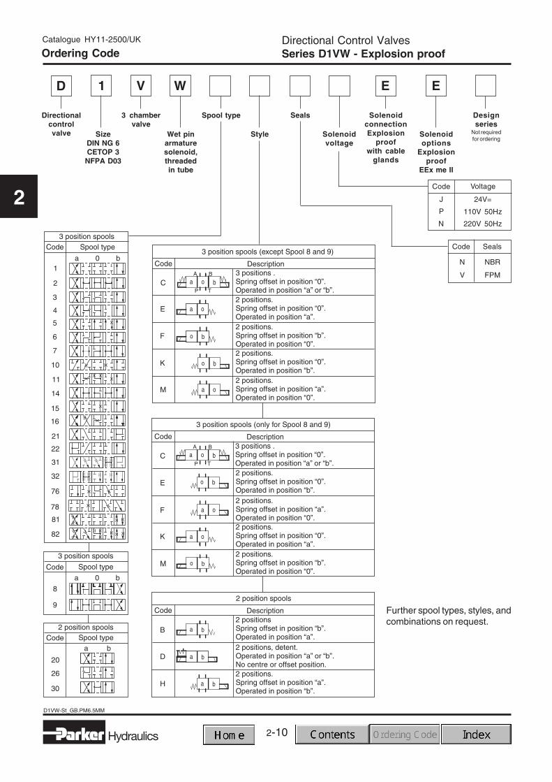
Directional Control ValvesSeries D1VW - Explosion proofOrdering Code
WD V
Directionalcontrolvalve Wet pin
armaturesolenoid,threadedin tube
3 chambervalve
Solenoidoptions
Explosionproof
EEx me II
SolenoidconnectionExplosion
proofwith cable
glands
Designseries
Not requiredfor ordering
Solenoidvoltage
Seals
Code
N NBR
V FPM
Seals
Style
Further spool types, styles, andcombinations on request.
1
SizeDIN NG 6CETOP 3
NFPA D03
Code Voltage
110V 50Hz
220V 50Hz
P
N
E E
24V=J
Spool type
2-11
2
Hydraulics
D1VW-St_GB.PM6.5MM
Catalogue HY11-2500/UK
2
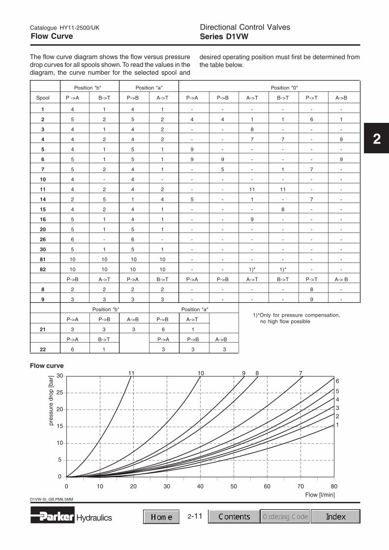
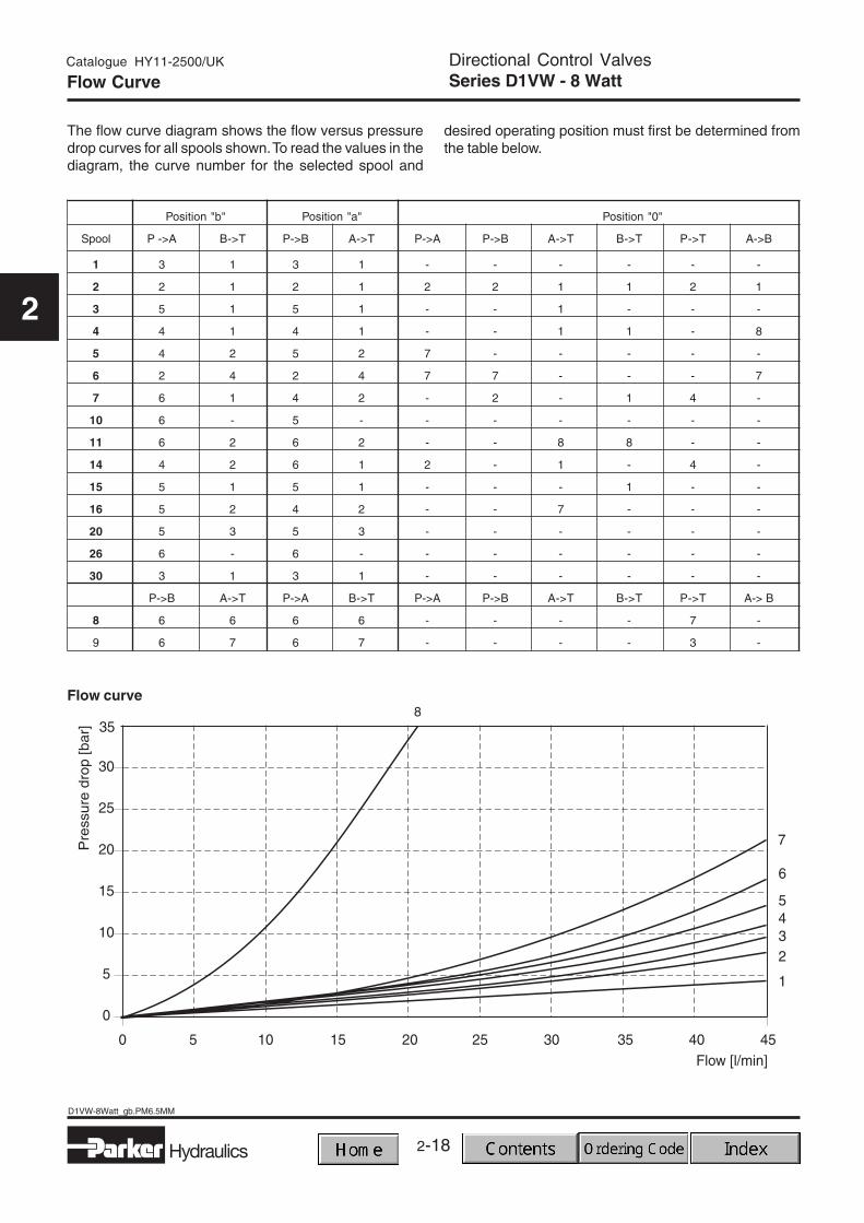
Directional Control ValvesSeries D1VWFlow Curve
The flow curve diagram shows the flow versus pressuredrop curves for all spools shown. To read the values in thediagram, the curve number for the selected spool and
desired operating position must first be determined fromthe table below.
1)*Only for pressure compensation,no high flow possible
2-12
D1VW-St_GB.PM6.5MM
Hydraulics
Catalogue HY11-2500/UK
2
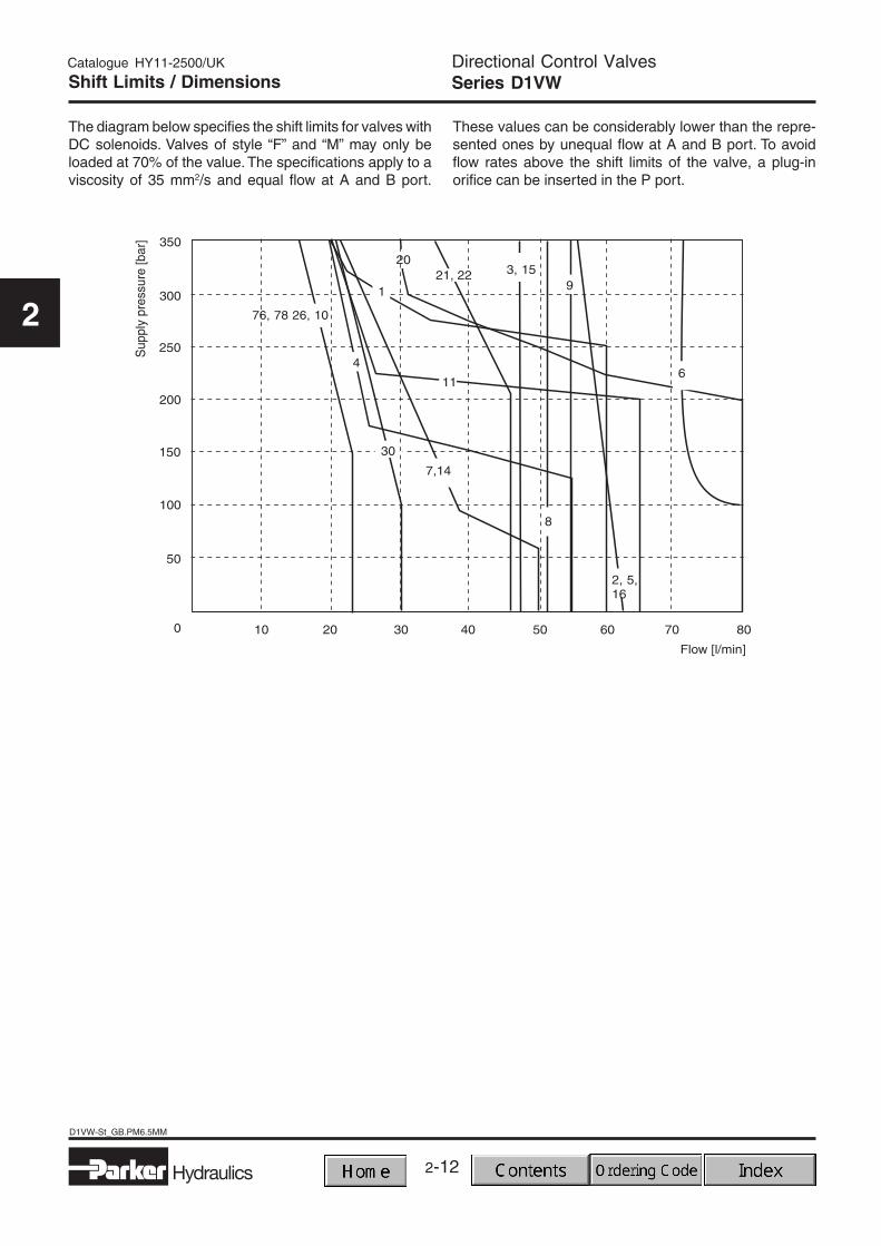
Directional Control ValvesSeries D1VWShift Limits / Dimensions
The diagram below specifies the shift limits for valves withDC solenoids. Valves of style “F” and “M” may only beloaded at 70% of the value. The specifications apply to aviscosity of 35 mm2/s and equal flow at A and B port.
These values can be considerably lower than the repre-sented ones by unequal flow at A and B port. To avoidflow rates above the shift limits of the valve, a plug-inorifice can be inserted in the P port.
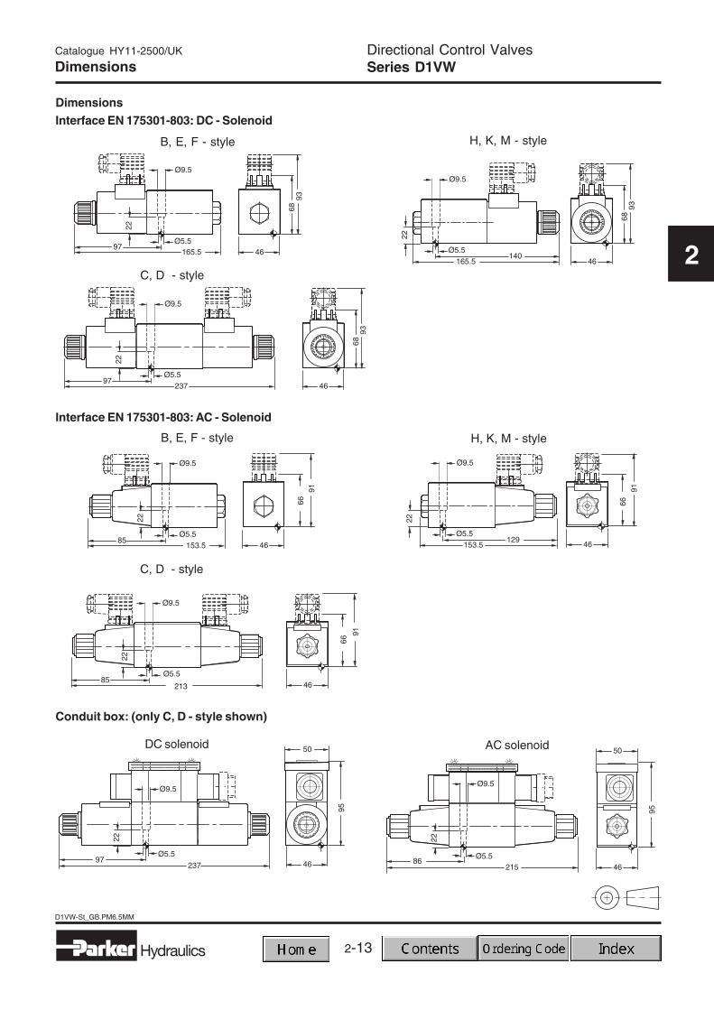
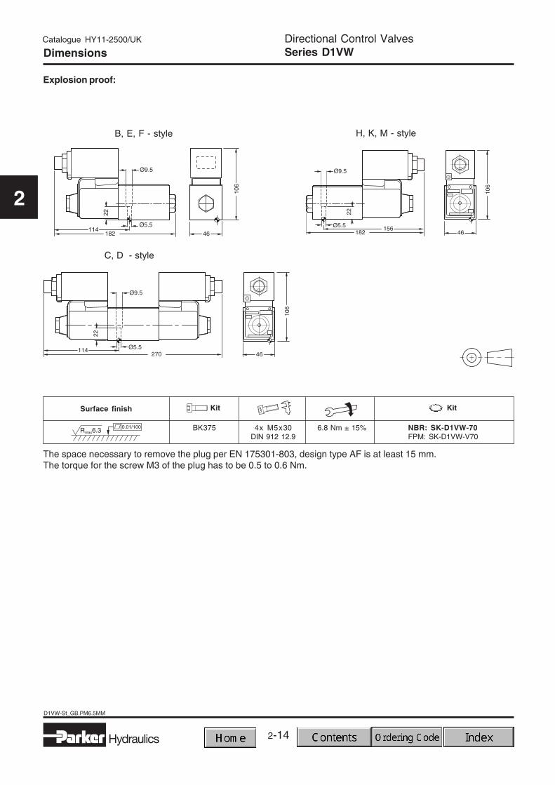
The space necessary to remove the plug per EN 175301-803, design type AF is at least 15 mm.The torque for the screw M3 of the plug has to be 0.5 to 0.6 Nm.
2-15
D1VW-8Watt._gbPM6.5MM
Hydraulics
Catalogue HY11-2500/UK
2
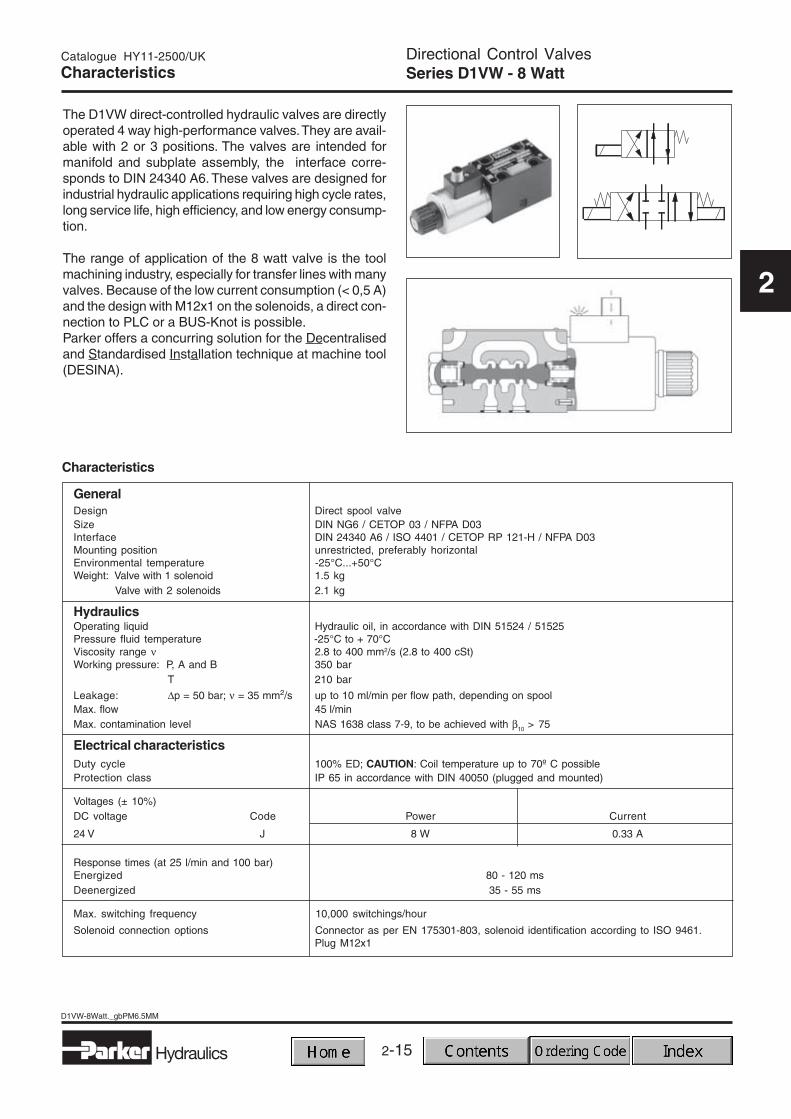
Directional Control ValvesSeries D1VW - 8 WattCharacteristics
The D1VW direct-controlled hydraulic valves are directlyoperated 4 way high-performance valves. They are avail-able with 2 or 3 positions. The valves are intended formanifold and subplate assembly, the interface corre-sponds to DIN 24340 A6. These valves are designed forindustrial hydraulic applications requiring high cycle rates,long service life, high efficiency, and low energy consump-tion.
The range of application of the 8 watt valve is the toolmachining industry, especially for transfer lines with manyvalves. Because of the low current consumption (< 0,5 A)and the design with M12x1 on the solenoids, a direct con-nection to PLC or a BUS-Knot is possible.Parker offers a concurring solution for the Decentralisedand Standardised Installation technique at machine tool(DESINA).
Characteristics
GeneralDesign Direct spool valveSize DIN NG6 / CETOP 03 / NFPA D03Interface DIN 24340 A6 / ISO 4401 / CETOP RP 121-H / NFPA D03Mounting position unrestricted, preferably horizontalEnvironmental temperature -25°C...+50°CWeight: Valve with 1 solenoid 1.5 kg
Valve with 2 solenoids 2.1 kg
HydraulicsOperating liquid Hydraulic oil, in accordance with DIN 51524 / 51525Pressure fluid temperature -25°C to + 70°CViscosity range ν 2.8 to 400 mm2/s (2.8 to 400 cSt)Working pressure: P, A and B 350 bar
T 210 bar
Leakage: ∆p = 50 bar; ν = 35 mm2/s up to 10 ml/min per flow path, depending on spoolMax. flow 45 l/minMax. contamination level NAS 1638 class 7-9, to be achieved with β10 > 75
Electrical characteristicsDuty cycle 100% ED; CAUTION: Coil temperature up to 70º C possibleProtection class IP 65 in accordance with DIN 40050 (plugged and mounted)
Voltages (± 10%)DC voltage Code Power Current
24 V J 8 W 0.33 A
Response times (at 25 l/min and 100 bar)Energized 80 - 120 msDeenergized 35 - 55 ms
Max. switching frequency 10,000 switchings/hour
Solenoid connection options Connector as per EN 175301-803, solenoid identification according to ISO 9461.Plug M12x1
2-16
D1VW-8Watt_gb.PM6.5MM
Hydraulics
Catalogue HY11-2500/UK
2
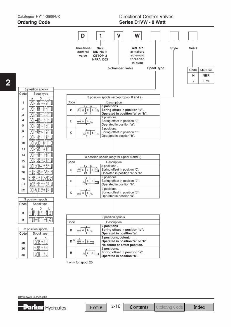
Ordering CodeDirectional Control ValvesSeries D1VW - 8 Watt
WD V
Directionalcontrol
valve
Wet pinarmaturesolenoidthreadedin tube
3-chamber valve
Seals
Code
N NBR
V FPM
Material
Style
1
SizeDIN NG 6CETOP 3
NFPA D03
Spool type
1) only for spool 20.
2-17
D1VW-8Watt._gbPM6.5MM
Hydraulics
Catalogue HY11-2500/UK
2
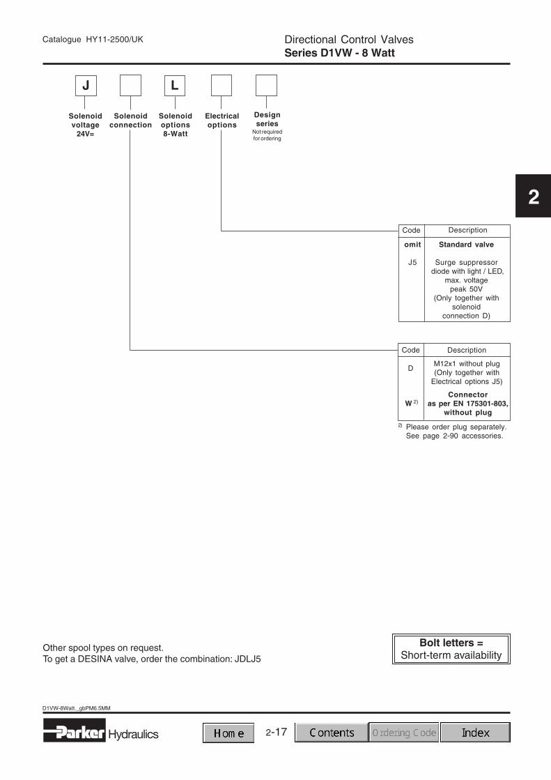
Solenoidoptions8-Watt
Solenoidconnection
Designseries
Not requiredfor ordering
Solenoidvoltage
24V=
Electricaloptions
Code Description
omit Standard valve
J5 Surge suppressor diode with light / LED,
max. voltagepeak 50V
(Only together withsolenoid
connection D)
Code Description
2) Please order plug separately.See page 2-90 accessories.
DM12x1 without plug(Only together with
Electrical options J5)
Connectoras per EN 175301-803,
without plugW 2)
Directional Control ValvesSeries D1VW - 8 Watt
Other spool types on request.To get a DESINA valve, order the combination: JDLJ5
J L
2-18
D1VW-8Watt_gb.PM6.5MM
Hydraulics
Catalogue HY11-2500/UK
2
The flow curve diagram shows the flow versus pressuredrop curves for all spools shown. To read the values in thediagram, the curve number for the selected spool and
desired operating position must first be determined fromthe table below.
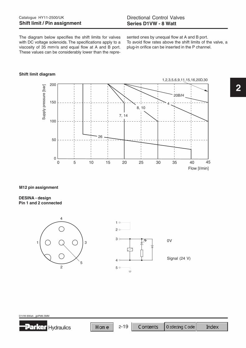
The diagram below specifies the shift limits for valveswith DC voltage solenoids. The specifications apply to aviscosity of 35 mm2/s and equal flow at A and B port.These values can be considerably lower than the repre-
sented ones by unequal flow at A and B port.To avoid flow rates above the shift limits of the valve, aplug-in orifice can be inserted in the P channel.
M12 pin assignment
0V
Signal (24 V)
DESINA - designPin 1 and 2 connected
Shift limit diagram
2-20
D1VW-8Watt_gb.PM6.5MM
Hydraulics
Catalogue HY11-2500/UK
2
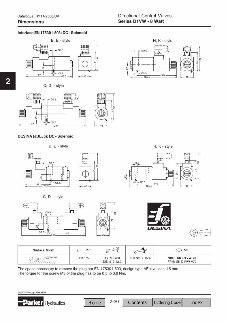
Directional Control ValvesSeries D1VW - 8 WattDimensions
The space necessary to remove the plug per EN 175301-803, design type AF is at least 15 mm.The torque for the screw M3 of the plug has to be 0.5 to 0.6 Nm.
2-21
2
Hydraulics
D1VW-Softshift_gb.PM6.5MM
Catalogue HY11-2500/UK
2
Characteristics
GeneralDesign Directional spool valveSize DIN NG6 / CETOP 03 / NFPA D03Interface DIN 24340 A6 / ISO 4401 / CETOP RP 121-H / NFPA D03Mounting position unrestricted, preferably horizontalEnvironmental temperature -25°C...+50°CWeight: Valve with 1 solenoid 1.5 kg
Valve with 2 solenoids 2.1 kg
HydraulicsFluids Hydraulic oil, in accordance with DIN 51524 / 51525Fluid temperature -25°C to + 70°CViscosity range ν 2.8 to 400 mm2/s (2.8 to 400 cSt)Working pressure: P, A and B 350 bar
T Code “H”: 210 bar
Leakage: ∆p = 50 bar; ν = 35 mm2/s up to 10 ml/min per flow path, depending on spoolMax. flow 80 l/minMax. contamination level NAS 1638 class 7-9, to be achieved with β10 > 75
Electrical characteristicsDuty cycle 100% ED; CAUTION: Coil temperature up to 150º C possibleProtection class IP 65 in accordance with DIN 40050 (plugged and mounted)
Voltages (± 10%)
DC voltage Code Power Current
12 V K 30 W 2.5 A24 V J 30 W 1.25 A98 V U 30 W 0.31 A205 V G 30 W 0.15 A
Response times see table reponse time
Solenoid connection options Connector as per EN 175301-803, solenoid identification according to ISO 9461.
Directional Control ValvesSeries D1VW Soft ShiftCharacteristics
The D1VW soft shift is a 3 chamber-, electrically con-trolled 4/3 or 4/2 way directional control valve. It is acti-vated directly by solenoids with screwed in wet pin ar-mature.The soft shifting of the valve is achieved by damping theplunger in the tube with an orifice.
Orifice in plunger
2-22
D1VW-Softshift_gb.PM6.5MM
Hydraulics
Catalogue HY11-2500/UK
2
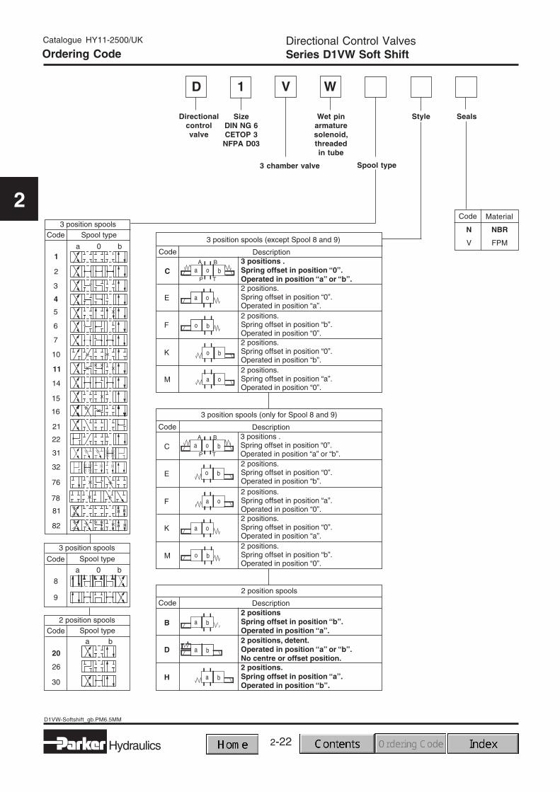
WD V
Directionalcontrolvalve
Wet pinarmaturesolenoid,threadedin tube
3 chamber valve
Directional Control ValvesSeries D1VW Soft ShiftOrdering Code
Seals
Code
N NBR
V FPM
Material
Style
Spool type
1
SizeDIN NG 6CETOP 3
NFPA D03
2-23
2
Hydraulics
D1VW-Softshift_gb.PM6.5MM
Catalogue HY11-2500/UK
2
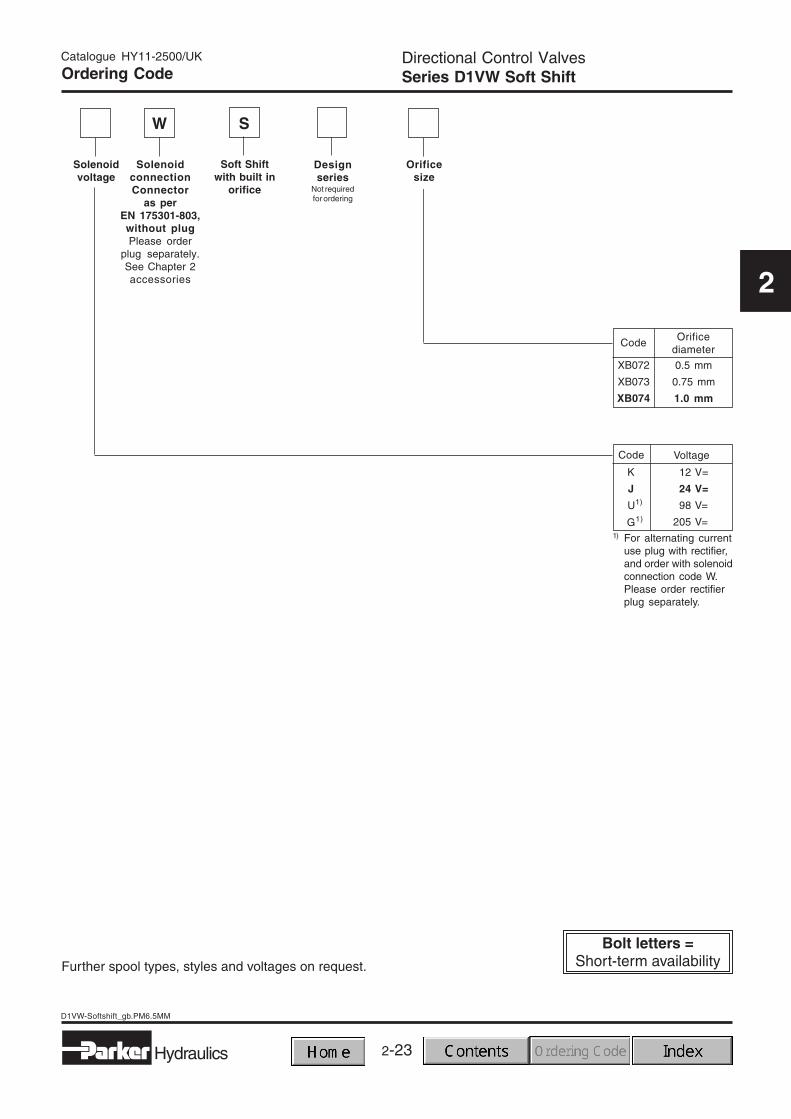
SolenoidconnectionConnector
as perEN 175301-803,without plugPlease order
plug separately.See Chapter 2accessories
Designseries
Not requiredfor ordering
Solenoidvoltage
Further spool types, styles and voltages on request.
Directional Control ValvesSeries D1VW Soft Shift
Code Voltage
U1)
G1)
12 V=
24 V=
98 V=
205 V=
K
J
S
Code Orificediameter
0.5 mm
0.75 mm
1.0 mm
XB072
XB073
XB074
Soft Shiftwith built in
orifice
Orificesize
1) For alternating currentuse plug with rectifier,and order with solenoidconnection code W.Please order rectifierplug separately.
W
Ordering Code
2-24
D1VW-Softshift_gb.PM6.5MM
Hydraulics
Catalogue HY11-2500/UK
2
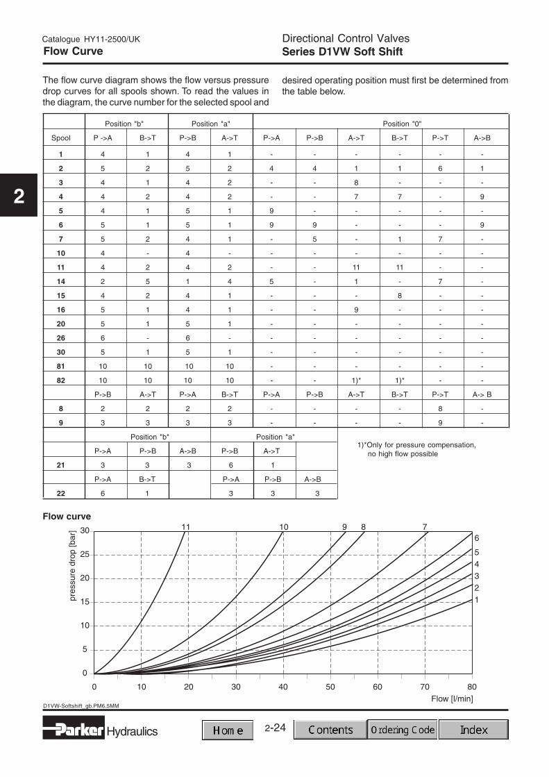
Directional Control ValvesSeries D1VW Soft ShiftFlow Curve
The flow curve diagram shows the flow versus pressuredrop curves for all spools shown. To read the values inthe diagram, the curve number for the selected spool and
desired operating position must first be determined fromthe table below.
1)*Only for pressure compensation,no high flow possible
2-25
2
Hydraulics
D1VW-Softshift_gb.PM6.5MM
Catalogue HY11-2500/UK
2
Directional Control ValvesSeries D1VW Soft ShiftShift limits / Dimensions
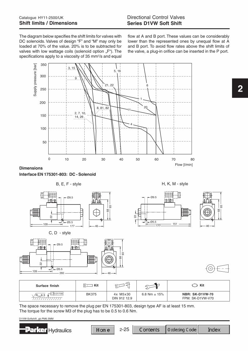
The diagram below specifies the shift limits for valves withDC solenoids. Valves of design “F” and “M” may only beloaded at 70% of the value. 20% is to be subtracted forvalves with low wattage coils (solenoid option „F“). Thespecifications apply to a viscosity of 35 mm2/s and equal
flow at A and B port. These values can be considerablylower than the represented ones by unequal flow at Aand B port. To avoid flow rates above the shift limits ofthe valve, a plug-in orifice can be inserted in the P port.
The space necessary to remove the plug per EN 175301-803, design type AF is at least 15 mm.The torque for the screw M3 of the plug has to be 0.5 to 0.6 Nm.
2-26
D1VW-Softshift_gb.PM6.5MM
Hydraulics
Catalogue HY11-2500/UK
2
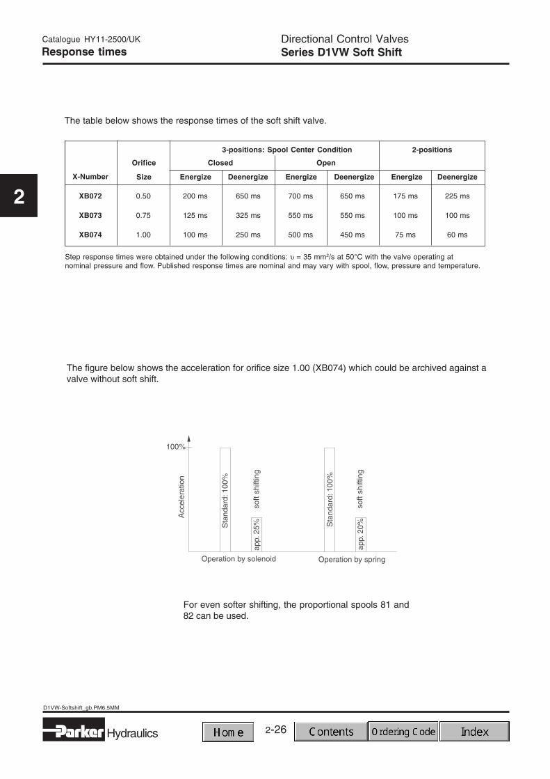
For even softer shifting, the proportional spools 81 and82 can be used.
Directional Control ValvesSeries D1VW Soft ShiftResponse times
X-Number
XB072 0.50 200 ms 650 ms 700 ms 650 ms 175 ms 225 ms
XB073 0.75 125 ms 325 ms 550 ms 550 ms 100 ms 100 ms
XB074 1.00 100 ms 250 ms 500 ms 450 ms 75 ms 60 ms
The table below shows the response times of the soft shift valve.
Step response times were obtained under the following conditions: υ = 35 mm2/s at 50°C with the valve operating atnominal pressure and flow. Published response times are nominal and may vary with spool, flow, pressure and temperature.
The figure below shows the acceleration for orifice size 1.00 (XB074) which could be archived against avalve without soft shift.
2-27
D1DW_gb.PM6.5MM
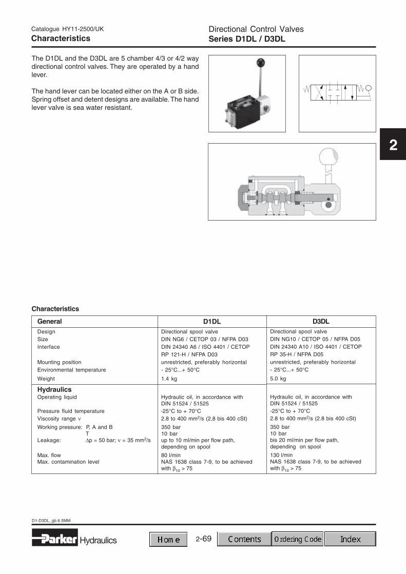
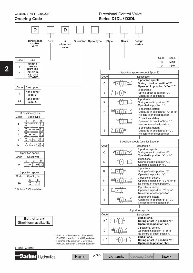
Directional Control ValvesSeries D1DW 5 Chamber Valve
Hydraulics
Catalogue HY11-2500/UK
2
Characteristics
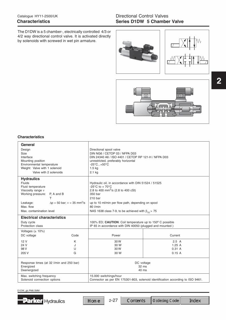
The D1DW is a 5 chamber-, electrically controlled 4/3 or4/2 way directional control valve. It is activated directlyby solenoids with screwed in wet pin armature.
Characteristics
GeneralDesign Directional spool valveSize DIN NG6 / CETOP 03 / NFPA D03Interface DIN 24340 A6 / ISO 4401 / CETOP RP 121-H / NFPA D03Mounting position unrestricted, preferably horizontalEnvironmental temperature -25°C...+50°CWeight: Valve with 1 solenoid 1.5 kg
Valve with 2 solenoids 2.1 kg
HydraulicsFluids Hydraulic oil, in accordance with DIN 51524 / 51525Fluid temperature -25°C to + 70°CViscosity range ν 2.8 to 400 mm2/s (2.8 to 400 cSt)Working pressure: P, A and B 350 bar
T 210 bar
Leakage: ∆p = 50 bar; ν = 35 mm2/s up to 10 ml/min per flow path, depending on spoolMax. flow 80 l/minMax. contamination level NAS 1638 class 7-9, to be achieved with β10 > 75
Electrical characteristicsDuty cycle 100% ED; CAUTION: Coil temperature up to 150º C possibleProtection class IP 65 in accordance with DIN 40050 (plugged and mounted )
Voltages (± 10%)DC voltage Code Power Current
12 V K 30 W 2.5 A24 V J 30 W 1.25 A98 V U 30 W 0.31 A205 V G 30 W 0.15 A
Response times (at 32 l/min and 250 bar) DC voltageEnergized 32 msDeenergized 40 ms
Max. switching frequency 15.000 switchings/hourSolenoid connection options Connector as per EN 175301-803, solenoid identification according to ISO 9461.
2-28
D1DW_gb.PM6.5MM
Hydraulics
Directional Control ValvesSeries D1DW 5 Chamber Valve
Catalogue HY11-2500/UK
2
WD D
Directionalcontrolvalve
Wet pinarmaturesolenoid,threadedin tube
5 chamber valve
Ordering Code
Seals
Code
N NBRV FPM
Material
Style
1
SizeDIN NG 6CETOP 3
NFPA D03
Spool type
Catalogue HY11-2500/UK
2-29
D1DW_gb.PM6.5MM
Directional Control ValvesSeries D1DW 5 Chamber Valve
Hydraulics
2
Solenoidoptions
SolenoidconnectionConnector
as perEN 175301-803,without plugPlease orderplug sepa-rately. SeeCapter 2
accessories
Designseries
Not requiredfor ordering
Solenoidvoltage
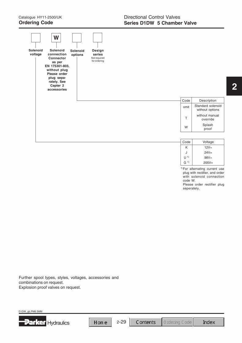
Further spool types, styles, voltages, accessories andcombinations on request.Explosion proof valves on request.
Code Voltage
1) For alternating current useplug with rectifier, and orderwith solenoid connectioncode W.Please order rectifier plugseperately.
Code Description
Standard solenoidwithout options
omit
without manualoverrideT
SplashproofW
12V=
24V=
98V=
205V=
K
J
U 1)
G 1)
W
Ordering Code
2-30
D1DW_gb.PM6.5MM
Hydraulics
Directional Control ValvesSeries D1DW 5 Chamber Valve
Catalogue HY11-2500/UK
2
Flow Curve
The flow curve diagram shows the flow versus pressuredrop curves for all spools shown. To read the values in thediagram, the curve number for the selected spool and
desired operating position must first be determined fromthe table below.
1)*Only for pressure compensation,no high flow possible
2-31
D1DW_gb.PM6.5MM
Directional Control ValvesSeries D1DW 5 Chamber Valve
Hydraulics
Catalogue HY11-2500/UK
2
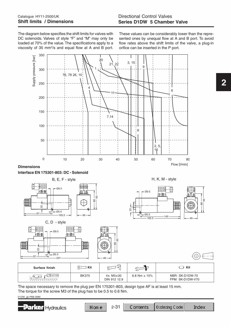
Shift limits / Dimensions
The diagram below specifies the shift limits for valves withDC solenoids. Valves of style “F” and “M” may only beloaded at 70% of the value. The specifications apply to aviscosity of 35 mm2/s and equal flow at A and B port.
These values can be considerably lower than the repre-sented ones by unequal flow at A and B port. To avoidflow rates above the shift limits of the valve, a plug-inorifice can be inserted in the P port.
The space necessary to remove the plug per EN 175301-803, design type AF is at least 15 mm.The torque for the screw M3 of the plug has to be 0.5 to 0.6 Nm.
2-32
D1VW_DW-Pos_gbPM6.5MM
Hydraulics
Catalogue HY11-2500/UK
2
Characteristics
GeneralDesign Directional spool valveNominal size DIN NG6 / CETOP 03 / NFPA D03Interface DIN 24340 A6 / ISO 4401 / CETOP RP 121-H / NFPA D03Mounting position unrestricted, preferably horizontalEnvironmental temperature 0°C...+50°CWeight: Valve with 1 solenoid 1.8 kg
HydraulicsOperating liquid Hydraulic oil, in accordance with DIN 51524 / 51525Pressure fluid temperature -25°C to + 70°CViscosity range ν 2.8 to 400 mm2/s (2.8 to 400 cSt)Working pressure: P, A and B 350 bar
T 210 bar
Leakage: ∆p = 50 bar; ν = 35 mm2/s up to 10 ml/min per flow path, depending on spoolMax. flow 80 l/minMax. contamination level NAS 1638 class 7-9, to be achieved with β10 > 75
Electric system - solenoidDuty cycle 100% ED; CAUTION: Coil temperature up to 150° C possibleProtection class IP 65 in accordance with DIN 40050 (plugged and mounted)
Voltages (± 10%) D1VW / D1DW
DC voltage Code Power Current
12 V K 30 W 2.5 A24 V J 30 W 1.25 A98 V U 30 W 0.31 A205 V G 30 W 0.15 A
Response times (at 32 l/min and 250 bar)
Energized / deenergized 32 ms / 40 ms
Max. switching frequency 15000 switchings/hourSolenoid connection options Connector as per EN 175301-803, solenoid identification according to ISO 9461.
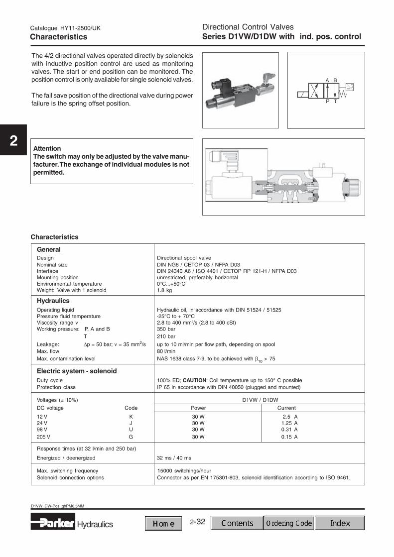
Directional Control ValvesSeries D1VW/D1DW with ind. pos. controlCharacteristics
The 4/2 directional valves operated directly by solenoidswith inductive position control are used as monitoringvalves. The start or end position can be monitored. Theposition control is only available for single solenoid valves.
The fail save position of the directional valve during powerfailure is the spring offset position.
AttentionThe switch may only be adjusted by the valve manu-facturer. The exchange of individual modules is notpermitted.
2-33
2
Hydraulics
D1VW_DW-Pos_gbPM6.5MM
Catalogue HY11-2500/UK
2
Directional Control ValvesSeries D1VW/D1DW with ind. pos. controlCharacteristics
Electrical characteristics - position control M12x1
Supply voltage 18 - 42 VRipple 10%Max. output current (ohmic load) 400 mA
IP65 as per DIN 40050Protection class (plugged and mounted)
Max. tolerance < 1200 A/mmagnetic ambient field strength at 50 Hz
Minimum distance > 100 mmto the next AC solenoid
Definitions:Start position monitored:The valve is deenergized. The inductive switch gives asignal at the moment (below 15% spool stroke) when thespool leaves the spring offset position.
Pin assignment
End position monitored:The inductive switch gives a signal before ending thestroke (above 85% spool stroke).
The switch can only be located opposite the solenoid for direct-controlled valves. This means, if the solenoid islocated on the A side of the valve, the switch can only take place on the B side.
1 Normally open2 + Supply
18...42V3 Normally closed4 0V5 Earth ground
M12 x 1-plug
2-34
D1VW_DW-Pos_gbPM6.5MM
Hydraulics
Catalogue HY11-2500/UK
2
WD
Directionalcontrolvalve
Wet pinarmaturesolenoidthreadedin tube
Ordering Code
Seals
Code
N NBR
V FPM
Seals
Style
Spool type
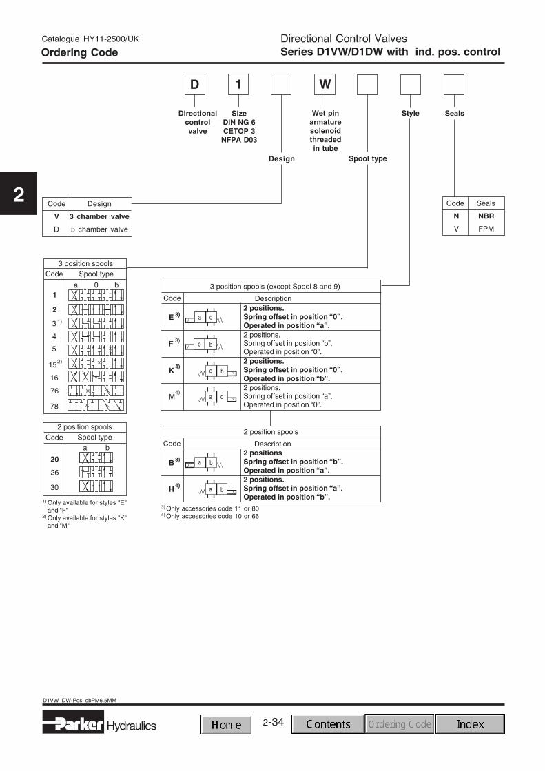
3) Only accessories code 11 or 804) Only accessories code 10 or 66
1
SizeDIN NG 6CETOP 3
NFPA D03
Directional Control ValvesSeries D1VW/D1DW with ind. pos. control
Code Design
V 3 chamber valve
D 5 chamber valve
1) Only available for styles "E"and "F"
2) Only available for styles "K"and "M"
Design
2-35
2
Hydraulics
D1VW_DW-Pos_gbPM6.5MM
Catalogue HY11-2500/UK
2
Solenoidoptions
SolenoidconnectionConnector
as perEN 175301-803,without plugPlease order
plug separately.See Chapter 2accessories
Designseries
Not requiredfor ordering
Solenoidvoltage
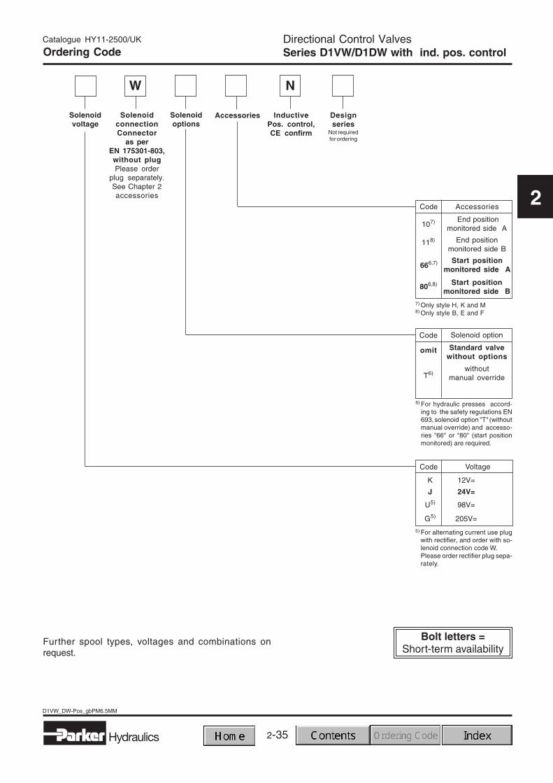
Accessories
Further spool types, voltages and combinations onrequest.
Code Voltage
Code Accessories
End positionmonitored side B
107)
118)
End positionmonitored side A
Start positionmonitored side B
806,8)
7) Only style H, K and M8) Only style B, E and F
5) For alternating current use plugwith rectifier, and order with so-lenoid connection code W.Please order rectifier plug sepa-rately.
Start positionmonitored side A666,7)
Code Solenoid option
Standard valvewithout options
omit
withoutmanual override
K 12V=
J 24V=
U5) 98V=
G5) 205V=
Directional Control ValvesSeries D1VW/D1DW with ind. pos. control
T6)
6) For hydraulic presses accord-ing to the safety regulations EN693, solenoid option "T" (withoutmanual override) and accesso-ries "66" or "80" (start positionmonitored) are required.
W
InductivePos. control,CE confirm
N
Ordering Code
2-36
D1VW_DW-Pos_gbPM6.5MM
Hydraulics
Catalogue HY11-2500/UK
2
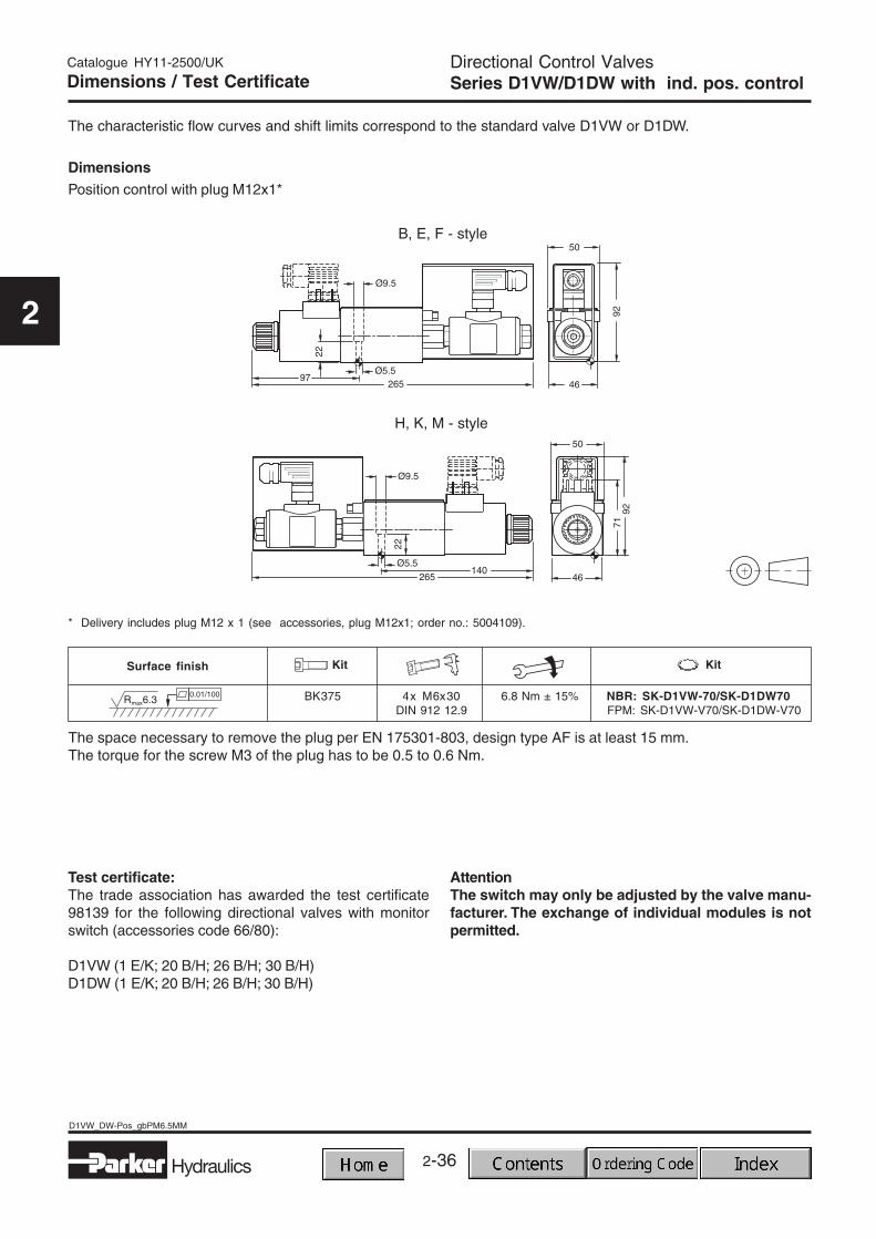
Dimensions / Test Certificate
The characteristic flow curves and shift limits correspond to the standard valve D1VW or D1DW.
Directional Control ValvesSeries D1VW/D1DW with ind. pos. control
AttentionThe switch may only be adjusted by the valve manu-facturer. The exchange of individual modules is notpermitted.
Test certificate:The trade association has awarded the test certificate98139 for the following directional valves with monitorswitch (accessories code 66/80):
The space necessary to remove the plug per EN 175301-803, design type AF is at least 15 mm.The torque for the screw M3 of the plug has to be 0.5 to 0.6 Nm.
2-37
2
Hydraulics
D3W_gb.PM6.5MM
Catalogue HY11-2500/UK
2
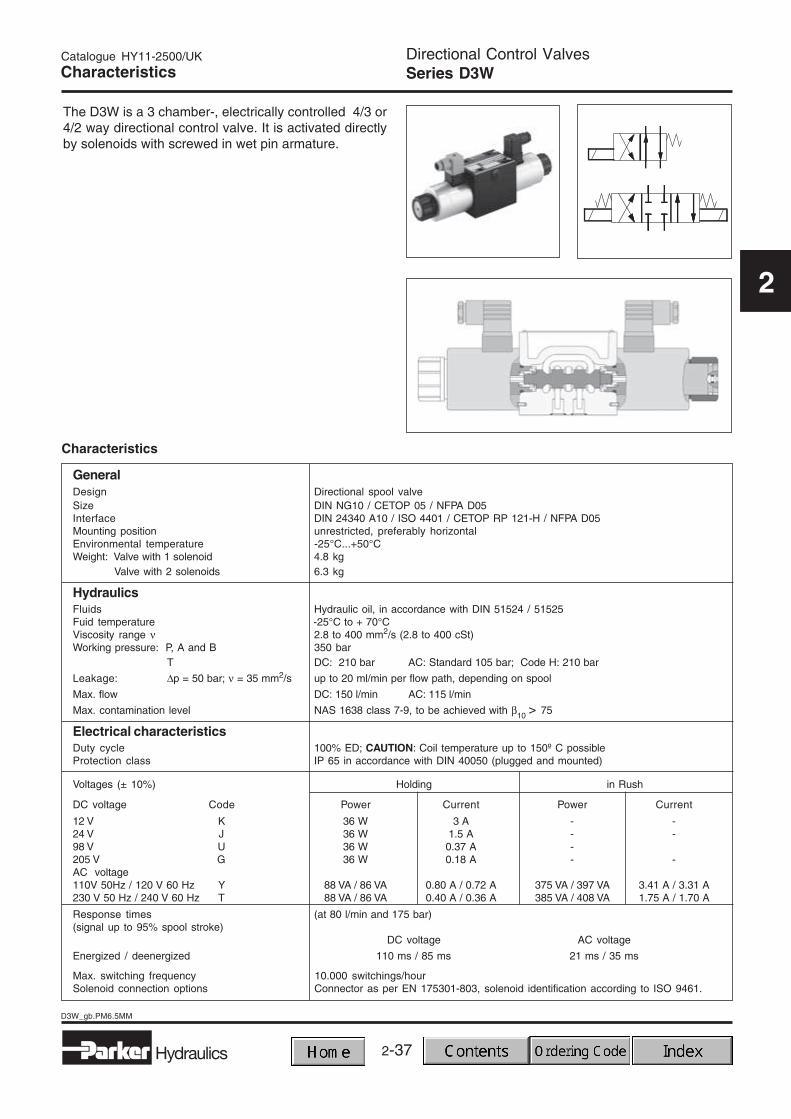
Directional Control ValvesSeries D3WCharacteristics
The D3W is a 3 chamber-, electrically controlled 4/3 or4/2 way directional control valve. It is activated directlyby solenoids with screwed in wet pin armature.
Characteristics
GeneralDesign Directional spool valveSize DIN NG10 / CETOP 05 / NFPA D05Interface DIN 24340 A10 / ISO 4401 / CETOP RP 121-H / NFPA D05Mounting position unrestricted, preferably horizontalEnvironmental temperature -25°C...+50°CWeight: Valve with 1 solenoid 4.8 kg
Valve with 2 solenoids 6.3 kg
HydraulicsFluids Hydraulic oil, in accordance with DIN 51524 / 51525Fuid temperature -25°C to + 70°CViscosity range ν 2.8 to 400 mm2/s (2.8 to 400 cSt)Working pressure: P, A and B 350 bar
T DC: 210 bar AC: Standard 105 bar; Code H: 210 bar
Leakage: ∆p = 50 bar; ν = 35 mm2/s up to 20 ml/min per flow path, depending on spool
Max. flow DC: 150 l/min AC: 115 l/min
Max. contamination level NAS 1638 class 7-9, to be achieved with β10 > 75
Electrical characteristicsDuty cycle 100% ED; CAUTION: Coil temperature up to 150º C possibleProtection class IP 65 in accordance with DIN 40050 (plugged and mounted)
Voltages (± 10%) Holding in Rush
DC voltage Code Power Current Power Current
12 V K 36 W 3 A - -24 V J 36 W 1.5 A - -98 V U 36 W 0.37 A -205 V G 36 W 0.18 A - -AC voltage110V 50Hz / 120 V 60 Hz Y 88 VA / 86 VA 0.80 A / 0.72 A 375 VA / 397 VA 3.41 A / 3.31 A230 V 50 Hz / 240 V 60 Hz T 88 VA / 86 VA 0.40 A / 0.36 A 385 VA / 408 VA 1.75 A / 1.70 A
Response times (at 80 l/min and 175 bar)(signal up to 95% spool stroke)
DC voltage AC voltage
Energized / deenergized 110 ms / 85 ms 21 ms / 35 ms
Max. switching frequency 10.000 switchings/hourSolenoid connection options Connector as per EN 175301-803, solenoid identification according to ISO 9461.
Further spool types, styles, and voltages on request.
Directional Control ValvesSeries D3W
Solenoid tubeoptions
Solenoidconnection
Designseries
Not requiredfor ordering
Solenoidvoltage
Code Voltage
110V 50Hz120V 60Hz
230V 50Hz240V 60Hz
Y
T
2) For AC voltage useplug with rectifier, andorder with solenoidconnection code W.Please order rectifierplug seperately.
Code Solenoid connection
3) Please order plug separately.See Chapter 2 accessories.
Conduit adapter withflying leads,
outlet on the front sideK
Connectoras per EN 175301-803,
without plugW3)
12V=
24V=
98V=
205V=
K
J
U2)
G2)
Accessories
Flying leads incavity, outlet on the
longitudinal sideC
Code Solenoid tube options
Standardsolenoid tube
(105 bar AC210 bar DC)
omit
High pressuresolenoid tube
tank press. 210bar(only for AC)
H
Manualoverrideoptions
Code Accessories
Signal light
Brad Harrison plug5 pin: 2 solenoids3 pin: 1 solenoid
Brad Harrison plug5 pin: 1solenoid
54)
Standard valveomit
65)
1A5)
Signal light withBrad Harrison plug5 pin: 2 solenoids3-pin: 1 solenoid
564)
Signal lightBrad Harrison plug5 pin: 1 solenoid
1C4)
without manualoverrideT
with manualoverrideomit
Code Manual override option
4) Only together with conduit adapter(code "K")
5) Only together with conduit adapter(code "K") or flying leads in cavity(code "C")
Ordering Code
2-40
D3W_gb.PM6.5MM
Hydraulics
Catalogue HY11-2500/UK
2
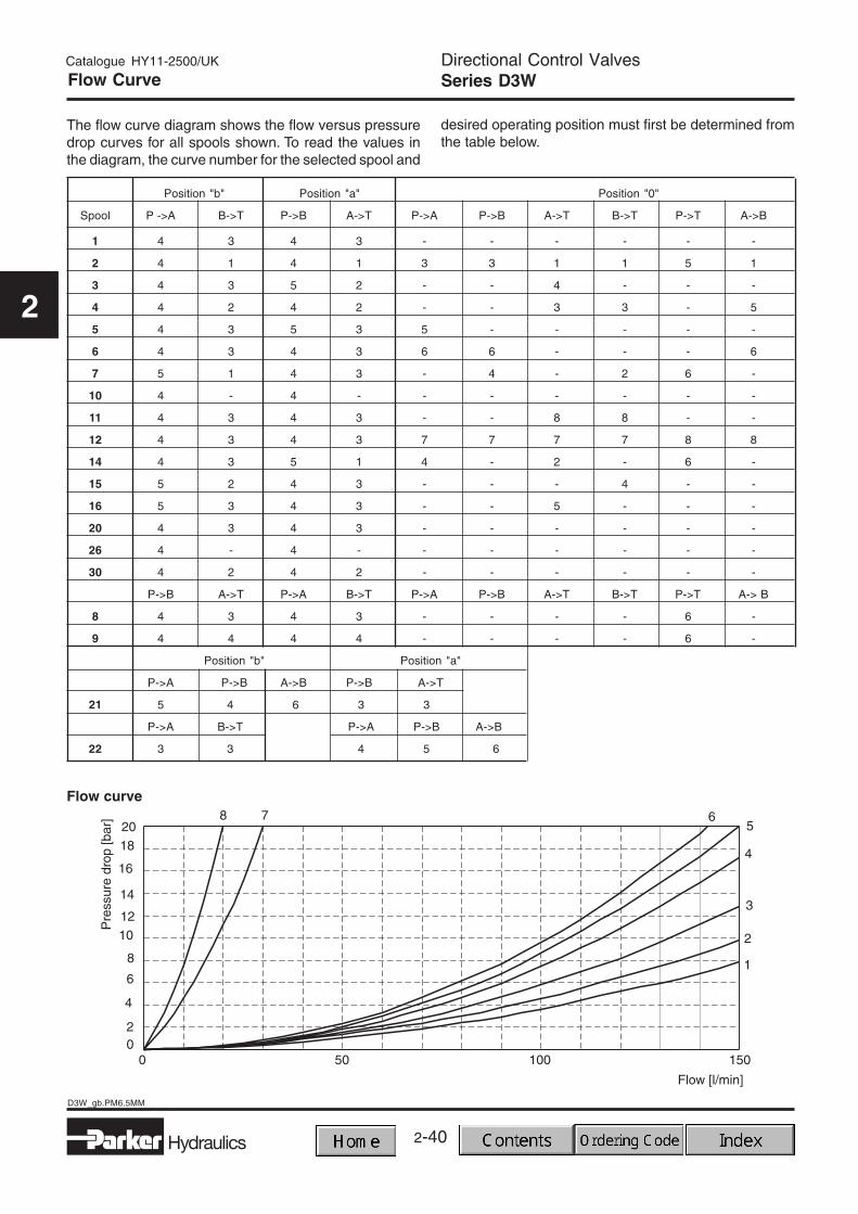
Directional Control ValvesSeries D3WFlow Curve
The flow curve diagram shows the flow versus pressuredrop curves for all spools shown. To read the values inthe diagram, the curve number for the selected spool and
desired operating position must first be determined fromthe table below.
The diagram below specifies the shift limits for valves withDC solenoids. Valves of style “F” and “M” may only beloaded at 70% of the value. The specifications apply to aviscosity of 35 mm2/s and equal flow at A and B port.
Directional Control ValvesSeries D3WShift Limits
Shift limits, AC voltage
Shift limits, DC voltage
Measured at 90% Unom and warmed-up solenoids.
These values can be considerably lower than the repre-sented ones by unequal flow at A and B port. To avoidflow rates above the shift limits of the valve, a plug-inorifice can be inserted in the P port.
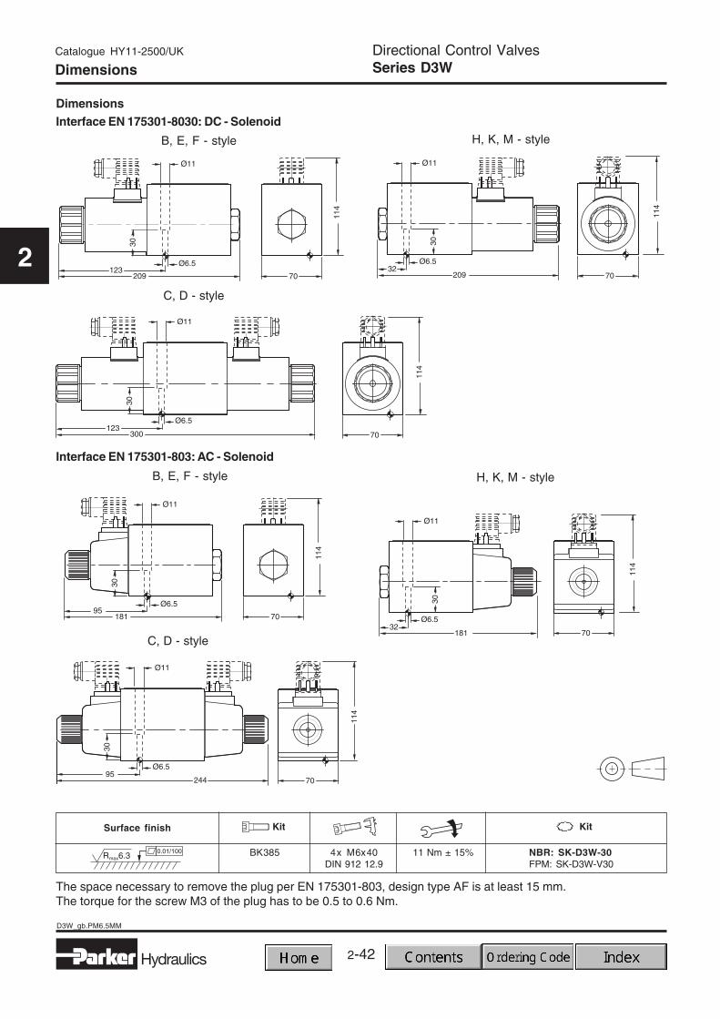
The space necessary to remove the plug per EN 175301-803, design type AF is at least 15 mm.The torque for the screw M3 of the plug has to be 0.5 to 0.6 Nm.
2-43
2
Hydraulics
D3DW_gb.PM6.5MM
Directional Control ValvesSeries D3DW - 5 Chamber Valve
Catalogue HY11-2500/UK
2
Characteristics
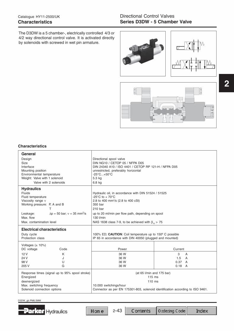
The D3DW is a 5 chamber-, electrically controlled 4/3 or4/2 way directional control valve. It is activated directlyby solenoids with screwed in wet pin armature.
Characteristics
GeneralDesign Directional spool valveSize DIN NG10 / CETOP 05 / NFPA D05Interface DIN 24340 A10 / ISO 4401 / CETOP RP 121-H / NFPA D05Mounting position unrestricted, preferably horizontalEnvironmental temperature -25°C...+50°CWeight: Valve with 1 solenoid 5.3 kg
Valve with 2 solenoids 6.8 kg
HydraulicsFluids Hydraulic oil, in accordance with DIN 51524 / 51525Fluid temperature -25°C to + 70°CViscosity range ν 2.8 to 400 mm2/s (2.8 to 400 cSt)Working pressure: P, A and B 350 bar
T 210 bar
Leakage: ∆p = 50 bar; ν = 35 mm2/s up to 20 ml/min per flow path, depending on spoolMax. flow 130 l/minMax. contamination level NAS 1638 class 7-9, to be achieved with β10 > 75
Electrical characteristicsDuty cycle 100% ED; CAUTION: Coil temperature up to 150º C possibleProtection class IP 65 in accordance with DIN 40050 (plugged and mounted)
Voltages (± 10%)DC voltage Code Power Current
12 V K 36 W 3 A24 V J 36 W 1.5 A98 V U 36 W 0.37 A205 V G 36 W 0.18 A
Response times (signal up to 95% spool stroke) (at 65 l/min and 175 bar)Energized 115 msdeenergized 110 msMax. switching frequency 10.000 switchings/hourSolenoid connection options Connector as per EN 175301-803, solenoid identification according to ISO 9461.
2-44
D3DW_gb.PM6.5MM
Hydraulics
Directional Control ValvesSeries D3DW - 5 Chamber Valve
Catalogue HY11-2500/UK
2
WD D
Directionalcontrolvalve
Wet pinarmaturesolenoid,threadedin tube
5 chambervalve
Ordering Code
SealsStyleSpool type
3
SizeDIN NG 10CETOP 5
NFPA D05
Code
N NBR
V FPM
Material
2-45
2
Hydraulics
D3DW_gb.PM6.5MM
Directional Control ValvesSeries D3DW - 5 Chamber Valve
Catalogue HY11-2500/UK
2
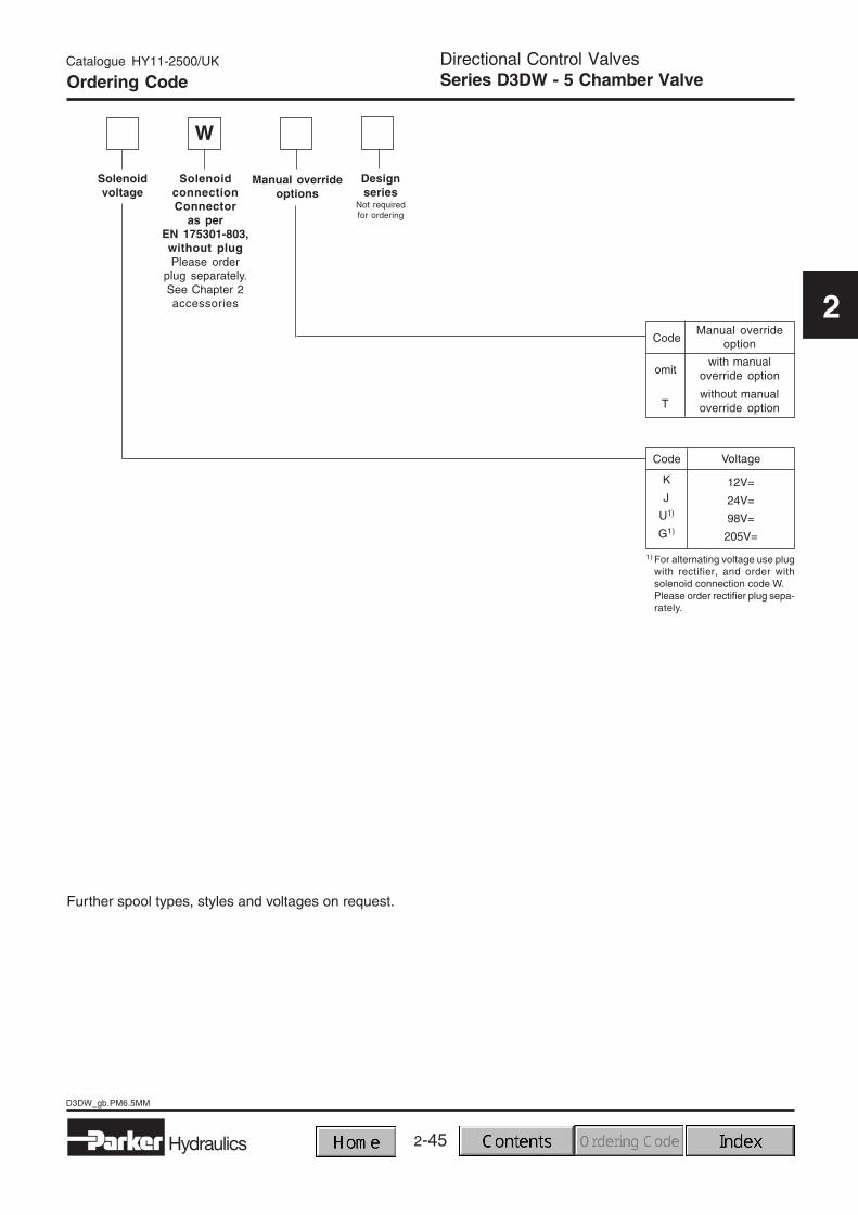
Further spool types, styles and voltages on request.
SolenoidconnectionConnector
as perEN 175301-803,without plugPlease order
plug separately.See Chapter 2accessories
Designseries
Not requiredfor ordering
Solenoidvoltage
Code Voltage
1) For alternating voltage use plugwith rectifier, and order withsolenoid connection code W.Please order rectifier plug sepa-rately.
12V=
24V=
98V=
205V=
K
J
U1)
G1)
without manualoverride optionT
with manualoverride optionomit
CodeManual override
option
Manual overrideoptions
W
Ordering Code
2-46
D3DW_gb.PM6.5MM
Hydraulics
Directional Control ValvesSeries D3DW - 5 Chamber Valve
Catalogue HY11-2500/UK
2
Flow Curve
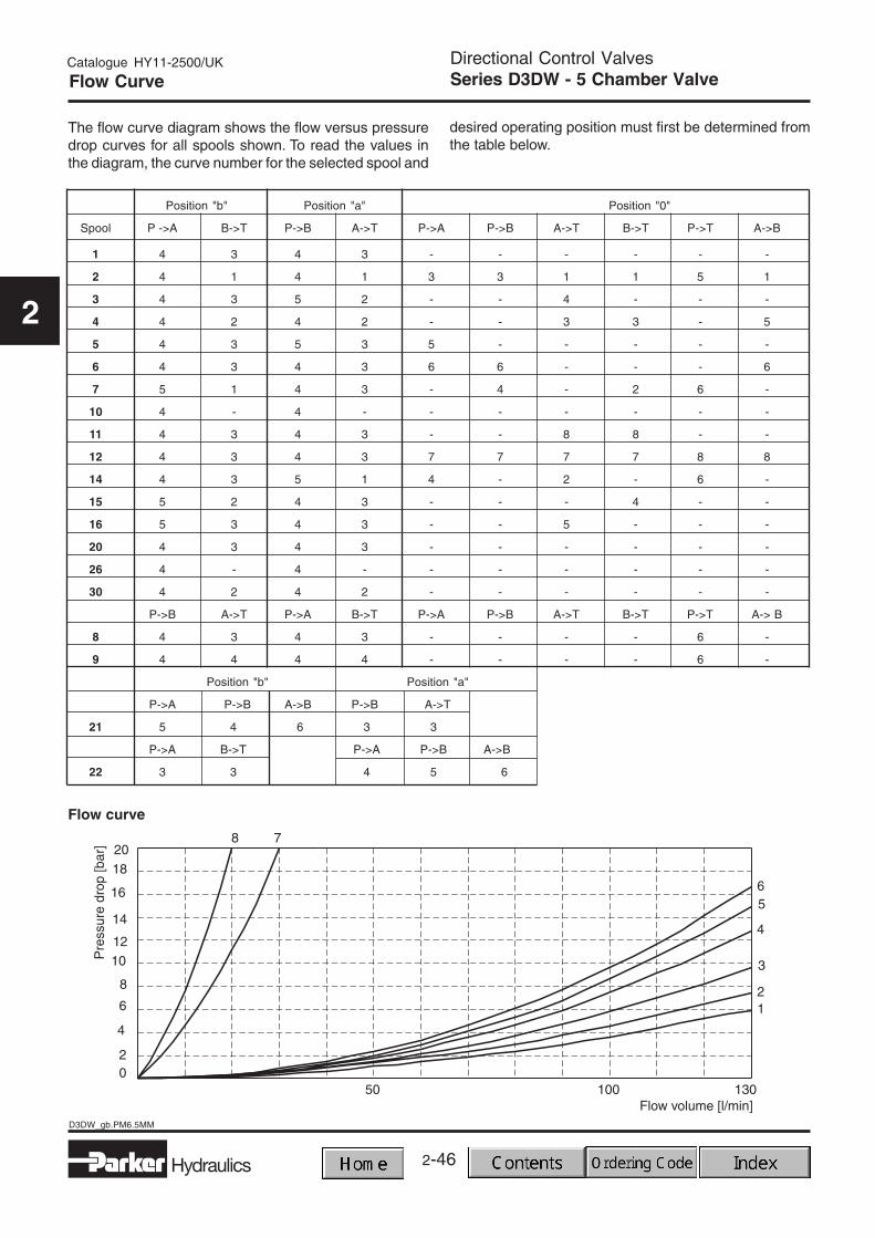
The flow curve diagram shows the flow versus pressuredrop curves for all spools shown. To read the values inthe diagram, the curve number for the selected spool and
desired operating position must first be determined fromthe table below.
Directional Control ValvesSeries D3DW - 5 Chamber Valve
Catalogue HY11-2500/UK
2
Shift Limits / Dimensions
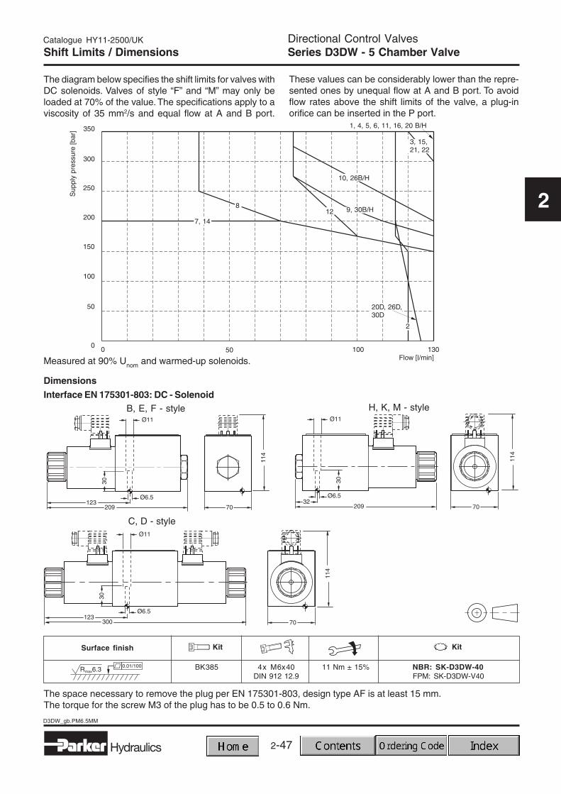
The diagram below specifies the shift limits for valves withDC solenoids. Valves of style “F” and “M” may only beloaded at 70% of the value. The specifications apply to aviscosity of 35 mm2/s and equal flow at A and B port.
These values can be considerably lower than the repre-sented ones by unequal flow at A and B port. To avoidflow rates above the shift limits of the valve, a plug-inorifice can be inserted in the P port.
The space necessary to remove the plug per EN 175301-803, design type AF is at least 15 mm.The torque for the screw M3 of the plug has to be 0.5 to 0.6 Nm.
Measured at 90% Unom and warmed-up solenoids.
2-48Hydraulics
D3W_DWPos_gb.PM6.5MM
Catalogue HY11-2500/UK
2
Directional Control ValvesSeries D3W/D3DW with ind. pos. controlCharacteristics
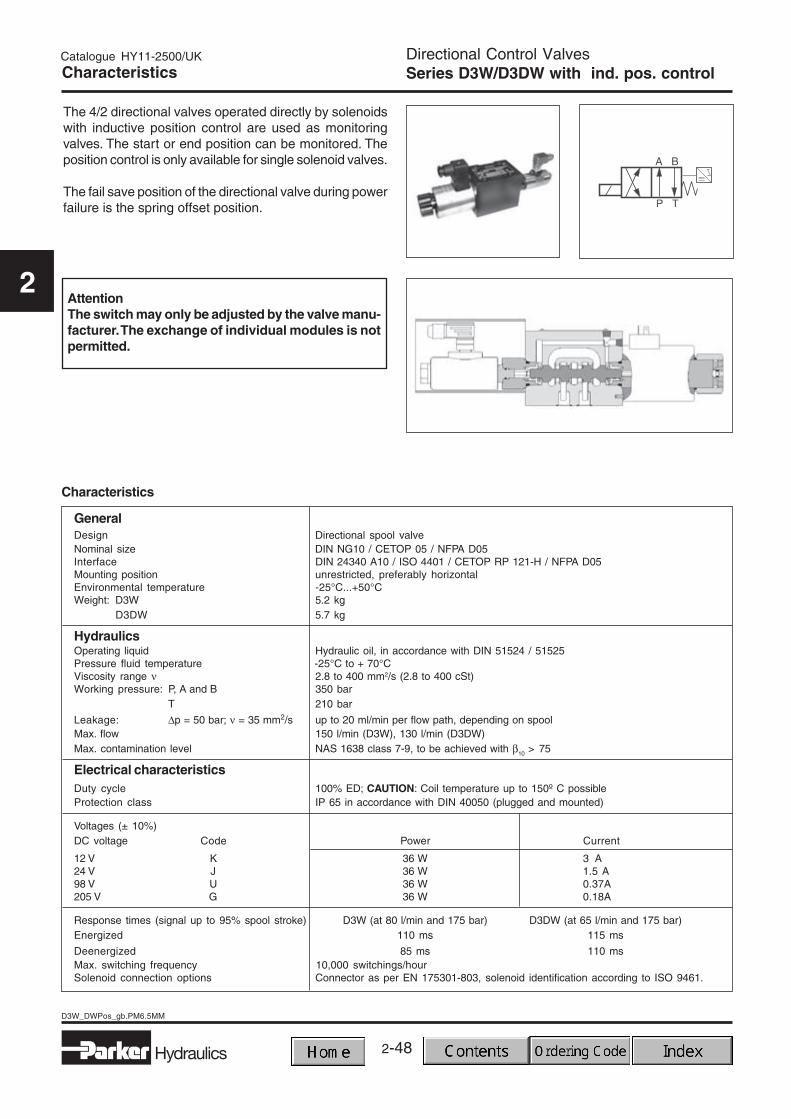
The 4/2 directional valves operated directly by solenoidswith inductive position control are used as monitoringvalves. The start or end position can be monitored. Theposition control is only available for single solenoid valves.
The fail save position of the directional valve during powerfailure is the spring offset position.
AttentionThe switch may only be adjusted by the valve manu-facturer. The exchange of individual modules is notpermitted.
Characteristics
GeneralDesign Directional spool valveNominal size DIN NG10 / CETOP 05 / NFPA D05Interface DIN 24340 A10 / ISO 4401 / CETOP RP 121-H / NFPA D05Mounting position unrestricted, preferably horizontalEnvironmental temperature -25°C...+50°CWeight: D3W 5.2 kg
D3DW 5.7 kg
HydraulicsOperating liquid Hydraulic oil, in accordance with DIN 51524 / 51525Pressure fluid temperature -25°C to + 70°CViscosity range ν 2.8 to 400 mm2/s (2.8 to 400 cSt)Working pressure: P, A and B 350 bar
T 210 bar
Leakage: ∆p = 50 bar; ν = 35 mm2/s up to 20 ml/min per flow path, depending on spoolMax. flow 150 l/min (D3W), 130 l/min (D3DW)Max. contamination level NAS 1638 class 7-9, to be achieved with β10 > 75
Electrical characteristicsDuty cycle 100% ED; CAUTION: Coil temperature up to 150º C possibleProtection class IP 65 in accordance with DIN 40050 (plugged and mounted)
Voltages (± 10%)DC voltage Code Power Current
12 V K 36 W 3 A24 V J 36 W 1.5 A98 V U 36 W 0.37A205 V G 36 W 0.18A
Response times (signal up to 95% spool stroke) D3W (at 80 l/min and 175 bar) D3DW (at 65 l/min and 175 bar)Energized 110 ms 115 ms
Deenergized 85 ms 110 msMax. switching frequency 10,000 switchings/hourSolenoid connection options Connector as per EN 175301-803, solenoid identification according to ISO 9461.
2-49
2
Hydraulics
D3W_DWPos_gb.PM6.5MM
Catalogue HY11-2500/UK
2
Directional Control ValvesSeries D3W/D3DW with ind. pos. controlCharacteristics
Electrical characteristics - position control M12x1
Supply voltage 18 - 42 VRipple 10%Max. output current (ohmic load) 400 mA
IP65 as per DIN 40050Protection class (plugged and mounted)
Max. tolerance < 1200 A/mmagnetic ambient field strength at 50 Hz
Minimum distance > 100 mmto the next AC solenoid
Definitions:Start position monitored:The valve is deenergized. The inductive switch gives asignal at the moment (below 15% spool stroke) when thespool leaves the spring offset position.
Pin assignment
End position monitored:The inductive switch gives a signal before ending thestroke (above 85% spool stroke).
The switch can only be located opposite the solenoid for direct-controlled valves. This means, if the solenoid islocated on the A side of the valve, the switch can only take place on the B side.
1 Normally open2 + Supply
18...42V3 Normally closed4 0V5 Earth ground
M12 x 1-plug
2-50Hydraulics
D3W_DWPos_gb.PM6.5MM
Catalogue HY11-2500/UK
2
Ordering Code
WD
Directionalcontrolvalve
Wet pinarmaturesolenoid,threadedin tube
SealsStyleSpool type
3
SizeDIN NG 10CETOP 5
NFPA D05
Directional Control ValvesSeries D3W/D3DW with ind. pos. control
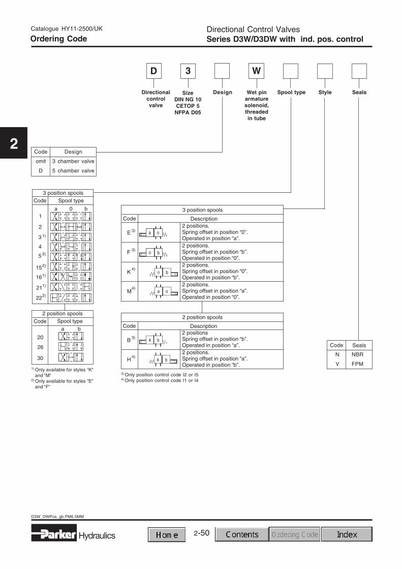
Code Design
omit 3 chamber valve
D 5 chamber valve
3) Only position control code I2 or I54) Only position control code I1 or I4
Code
N NBR
V FPM
Seals
1) Only available for styles "K"and "M"
2) Only available for styles "E"and "F"
Design
2-51
2
Hydraulics
D3W_DWPos_gb.PM6.5MM
Catalogue HY11-2500/UK
2
Directional Control ValvesSeries D3W/D3DW with ind. pos. control
SolenoidconnectionConnector
as perEN 175301-803,without plug
Please order plugseparately.See Chapter 2accessories
Designseries
Not requiredfor ordering
Solenoidvoltage
Positioncontrol
Code Voltage
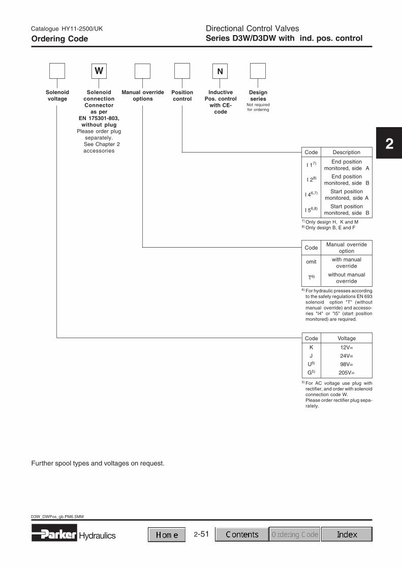
Code Description
I 17)
I 28)
I 56,8)
5) For AC voltage use plug withrectifier, and order with solenoidconnection code W.Please order rectifier plug sepa-rately.
I 46,7)
12V=
24V=
98V=
205V=
K
J
U5)
G5)
T6)
omit
CodeManual override
option
Manual overrideoptions
InductivePos. control
with CE-code
N
Further spool types and voltages on request.
End positionmonitored, side B
End positionmonitored, side A
Start positionmonitored, side B
Start positionmonitored, side A
without manualoverride
with manualoverride
6) For hydraulic presses accordingto the safety regulations EN 693solenoid option "T" (withoutmanual override) and accesso-ries "I4" or "I5" (start positionmonitored) are required.
7) Only design H, K and M8) Only design B, E and F
W
Ordering Code
2-52Hydraulics
D3W_DWPos_gb.PM6.5MM
Catalogue HY11-2500/UK
2
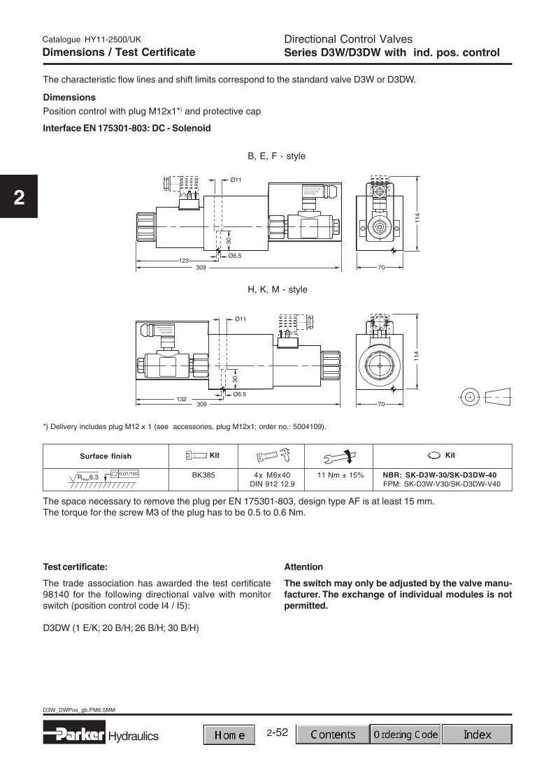
Dimensions
Dimensions / Test Certificate
The characteristic flow lines and shift limits correspond to the standard valve D3W or D3DW.
Directional Control ValvesSeries D3W/D3DW with ind. pos. control
Attention
The switch may only be adjusted by the valve manu-facturer. The exchange of individual modules is notpermitted.
Position control with plug M12x1*) and protective cap
Test certificate:
The trade association has awarded the test certificate98140 for the following directional valve with monitorswitch (position control code I4 / I5):
D3DW (1 E/K; 20 B/H; 26 B/H; 30 B/H)
*) Delivery includes plug M12 x 1 (see accessories, plug M12x1; order no.: 5004109).
The space necessary to remove the plug per EN 175301-803, design type AF is at least 15 mm.The torque for the screw M3 of the plug has to be 0.5 to 0.6 Nm.
2-53
2
Hydraulics
D1VP-3DP_GB.PM6.5MM
Directional Control ValvesSeries D1VP / D3DP
Catalogue HY11-2500/UK
2
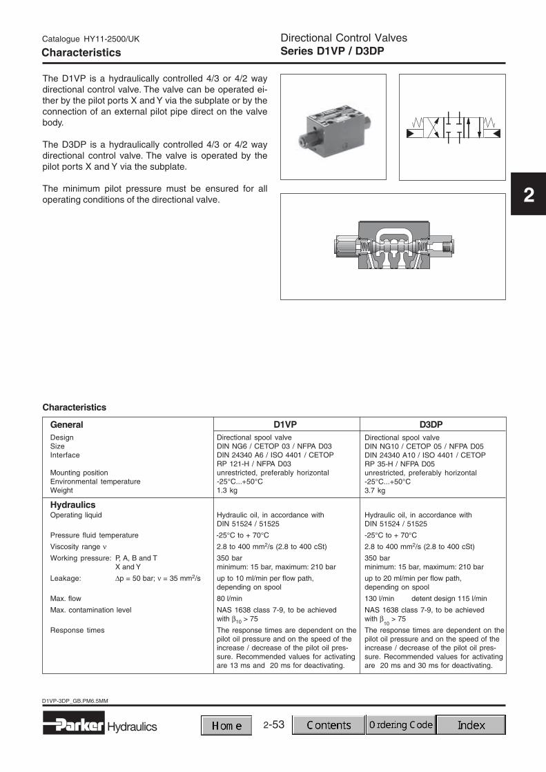
The D1VP is a hydraulically controlled 4/3 or 4/2 waydirectional control valve. The valve can be operated ei-ther by the pilot ports X and Y via the subplate or by theconnection of an external pilot pipe direct on the valvebody.
The D3DP is a hydraulically controlled 4/3 or 4/2 waydirectional control valve. The valve is operated by thepilot ports X and Y via the subplate.
The minimum pilot pressure must be ensured for alloperating conditions of the directional valve.
Characteristics
GeneralDesign Directional spool valveSize DIN NG6 / CETOP 03 / NFPA D03Interface DIN 24340 A6 / ISO 4401 / CETOP
RP 121-H / NFPA D03Mounting position unrestricted, preferably horizontalEnvironmental temperature -25°C...+50°CWeight 1.3 kg
HydraulicsOperating liquid Hydraulic oil, in accordance with
DIN 51524 / 51525
Pressure fluid temperature -25°C to + 70°C
Viscosity range ν 2.8 to 400 mm2/s (2.8 to 400 cSt)
Working pressure: P, A, B and T 350 barX and Y minimum: 15 bar, maximum: 210 bar
Leakage: ∆p = 50 bar; ν = 35 mm2/s up to 10 ml/min per flow path,depending on spool
Max. flow 80 l/min
Max. contamination level NAS 1638 class 7-9, to be achievedwith β10 > 75
Response times The response times are dependent on thepilot oil pressure and on the speed of theincrease / decrease of the pilot oil pres-sure. Recommended values for activatingare 13 ms and 20 ms for deactivating.
Hydraulic oil, in accordance withDIN 51524 / 51525
-25°C to + 70°C
2.8 to 400 mm2/s (2.8 to 400 cSt)
350 barminimum: 15 bar, maximum: 210 bar
up to 20 ml/min per flow path,depending on spool
130 l/min detent design 115 l/min
NAS 1638 class 7-9, to be achievedwith β
10 > 75
The response times are dependent on thepilot oil pressure and on the speed of theincrease / decrease of the pilot oil pres-sure. Recommended values for activatingare 20 ms and 30 ms for deactivating.
D1VP D3DP
2-54
D1VP-3DP_GB.PM6.5MM
Hydraulics
Directional Control ValvesSeries D1VP / D3DP
Catalogue HY11-2500/UK
2
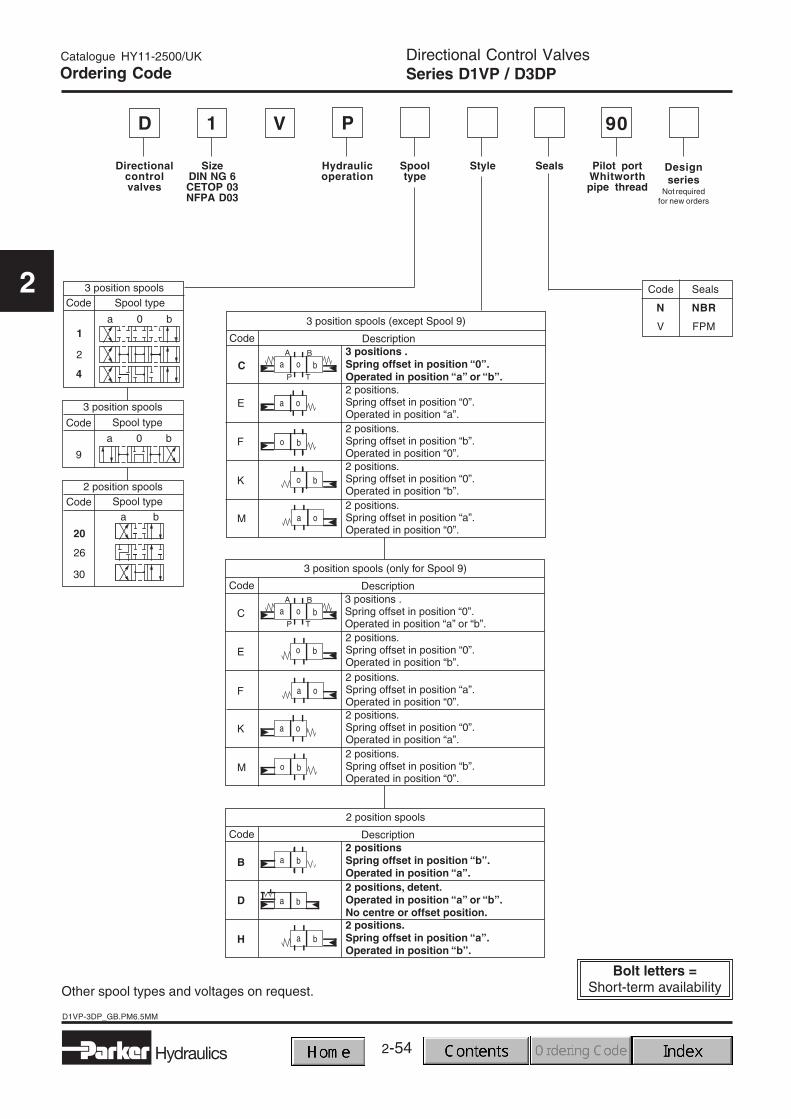
SizeDIN NG 6CETOP 03NFPA D03
Style Pilot portWhitworthpipe thread
Hydraulicoperation
Directionalcontrolvalves
1 90VD
Spooltype
Seals Designseries
Not requiredfor new orders
Other spool types and voltages on request.
Ordering Code
Code
N NBR
V FPM
Seals
P
2-55
2
Hydraulics
D1VP-3DP_GB.PM6.5MM
Directional Control ValvesSeries D1VP / D3DP
Catalogue HY11-2500/UK
2
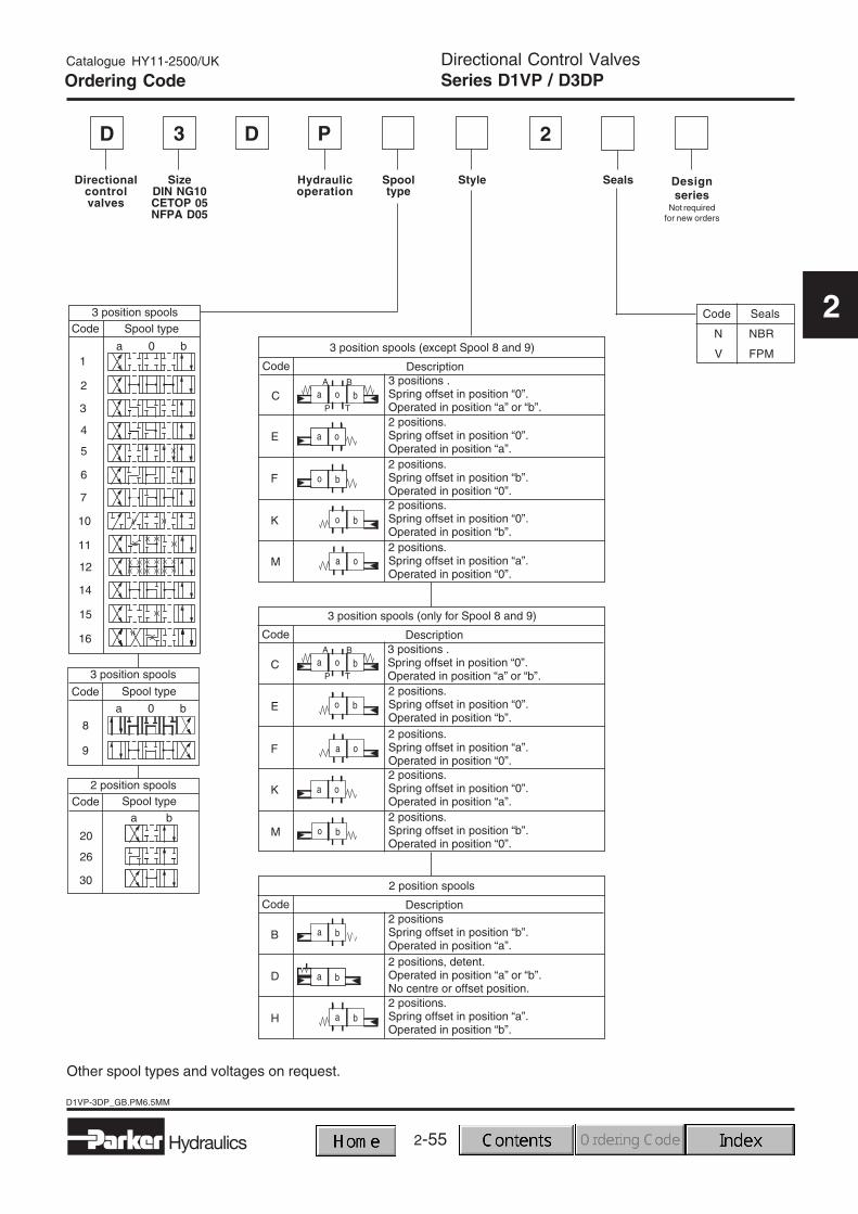
SizeDIN NG10CETOP 05NFPA D05
StyleHydraulicoperation
Directionalcontrolvalves
3 2DD
Spooltype
Seals Designseries
Not requiredfor new orders
Code
N NBR
V FPM
Seals
Ordering Code
P
Other spool types and voltages on request.
2-56
D1VP-3DP_GB.PM6.5MM
Hydraulics
Directional Control ValvesSeries D1VP / D3DP
Catalogue HY11-2500/UK
2
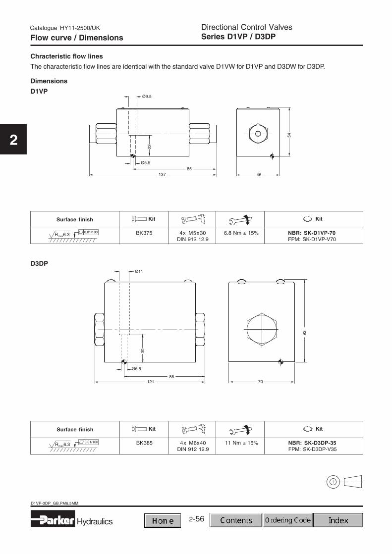
Flow curve / Dimensions
Dimensions
The characteristic flow lines are identical with the standard valve D1VW for D1VP and D3DW for D3DP.
Pilot Operated Directional Control ValvesSeries D4P - D11P
Catalogue HY11-2500/UK
2
Mounting patterns
Series Size Mounting pattern
General
The D4P, D9P and D11P are hydraulically controlled 4/3or 4/2 way directional control valves. The valves areoperated by the pilot ports X and Y via the subplate.Pressure and flow of the pilot oil have a significantinfluence on the response time of the spool.
The minimum pilot pressure must be ensured for alloperating conditions of the directional valve.
DIN NG16 DIN 24340 design A16CETOP 7 ISO 4401NFPA D07 CETOP RP 121
NFPA D07
DIN NG25 DIN 24340 design A25CETOP 8 ISO 4401NFPA D08 CETOP RP 121
NFPA D08
DIN NG32 DIN 24340 design A32CETOP 10 ISO 4401NFPA D10 CETOP RP 121
NFPA D10
D4
D9
D11
2-58
D4P-11P_GB.PM6.5MM
Hydraulics
Pilot Operated Directional Control ValvesSeries D4P - D11P
Catalogue HY11-2500/UK
2
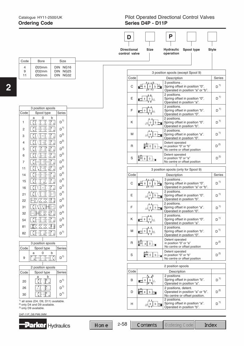
Directionalcontrol valve
D
Ordering Code
StyleSpool typeHydraulicoperation
Size
P
1) all sizes (D4, D9, D11) available.2) only D4 and D9 available.3) only D9 available.
Code Bore Size
4 Ø20mm DIN NG169 Ø32mm DIN NG25
11 Ø50mm DIN NG32
2-59Hydraulics
D4P-11P_GB.PM6.5MM
Pilot Operated Directional Control ValvesSeries D4P - D11P
Catalogue HY11-2500/UK
2
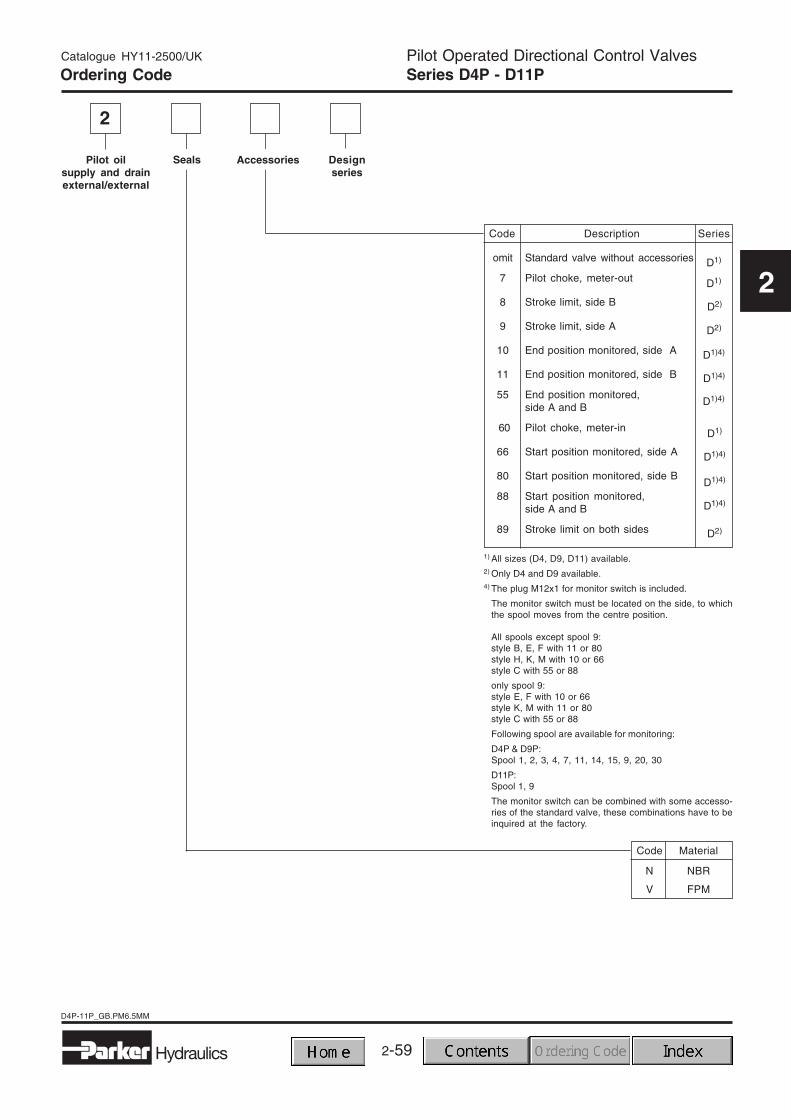
Designseries
Pilot oilsupply and drainexternal/external
Seals Accessories
Code Material
N NBR
V FPM
2
Code Description Series
omit Standard valve without accessories
7 Pilot choke, meter-out
8 Stroke limit, side B
9 Stroke limit, side A
10 End position monitored, side A
11 End position monitored, side B
55 End position monitored,side A and B
660 Pilot choke, meter-in
66 Start position monitored, side A
80 Start position monitored, side B
88 Start position monitored,side A and B
89 Stroke limit on both sides
D1)
D1)
D2)
D2)
D1)4)
D1)4)
D1)4)
D1)
D1)4)
D1)4)
D1)4)
D2)
Ordering Code
1) All sizes (D4, D9, D11) available.2) Only D4 and D9 available.4) The plug M12x1 for monitor switch is included.
The monitor switch must be located on the side, to whichthe spool moves from the centre position.
All spools except spool 9:style B, E, F with 11 or 80style H, K, M with 10 or 66style C with 55 or 88
only spool 9:style E, F with 10 or 66style K, M with 11 or 80style C with 55 or 88
Pilot oil on X Graphic symbol b (0)Y Graphic symbol a (0)
2-61Hydraulics
D4P-11P_GB.PM6.5MM
Pilot Operated Directional Control ValvesSeries D4P - D11P
Catalogue HY11-2500/UK
2
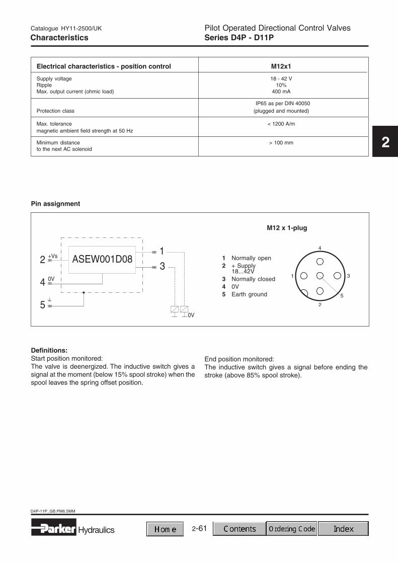
Electrical characteristics - position control M12x1
Supply voltage 18 - 42 VRipple 10%Max. output current (ohmic load) 400 mA
IP65 as per DIN 40050Protection class (plugged and mounted)
Max. tolerance < 1200 A/mmagnetic ambient field strength at 50 Hz
Minimum distance > 100 mmto the next AC solenoid
Definitions:Start position monitored:The valve is deenergized. The inductive switch gives asignal at the moment (below 15% spool stroke) when thespool leaves the spring offset position.
Pin assignment
End position monitored:The inductive switch gives a signal before ending thestroke (above 85% spool stroke).
1 Normally open2 + Supply
18...42V3 Normally closed4 0V5 Earth ground
M12 x 1-plug
Characteristics
2-62
D4P-11P_GB.PM6.5MM
Hydraulics
Pilot Operated Directional Control ValvesSeries D4P - D11P
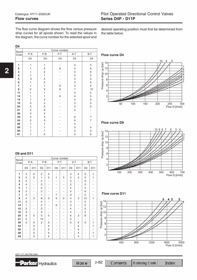
The flow curve diagram shows the flow versus pressuredrop curves for all spools shown. To read the values inthe diagram, the curve number for the selected spool and
desired operating position must first be determined fromthe table below.
Curve number
Curve number
2-63Hydraulics
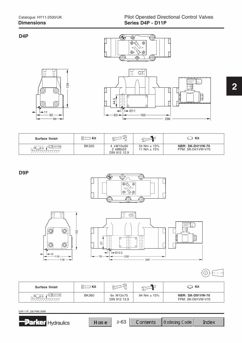
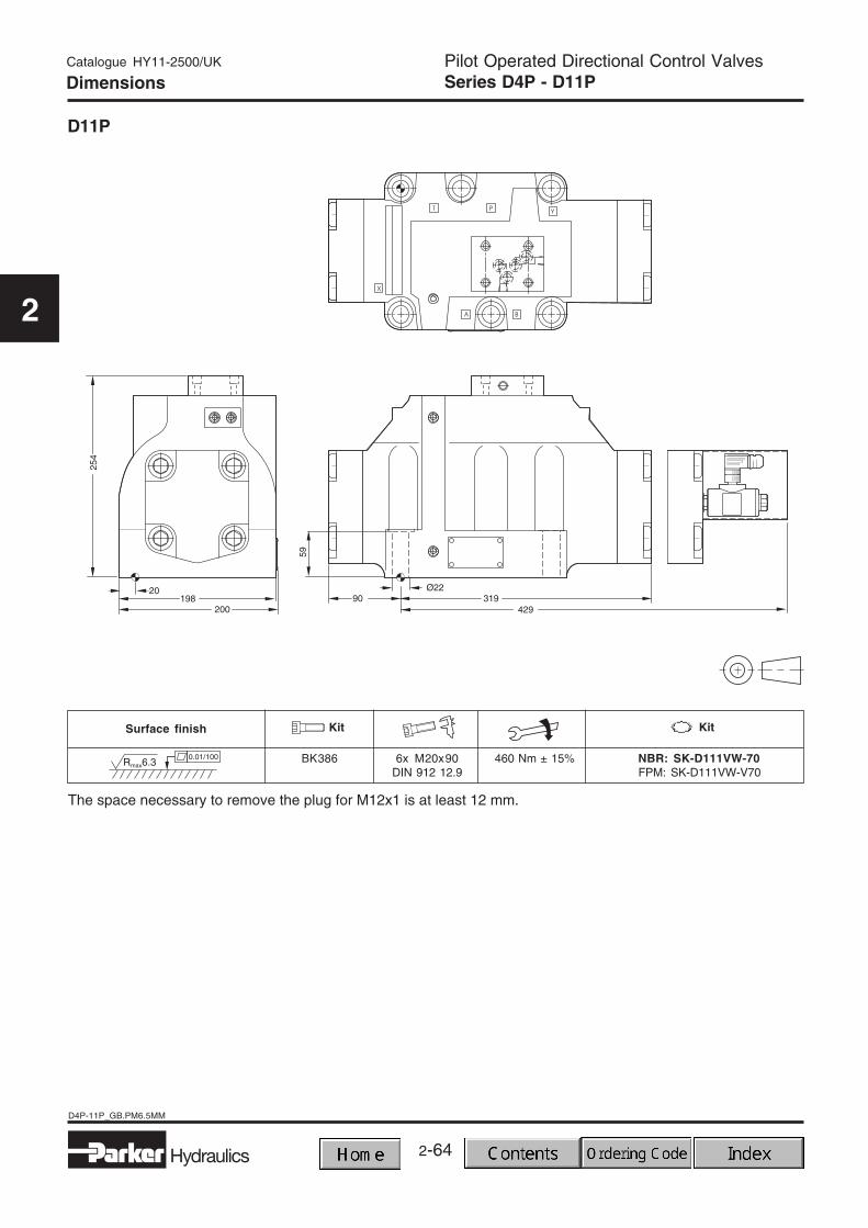
D4P-11P_GB.PM6.5MM
Pilot Operated Directional Control ValvesSeries D4P - D11P
The space necessary to remove the plug for M12x1 is at least 12 mm.
2-65
2
Hydraulics
D1VC-VD_gb.PM6.5MM
Directional Control ValvesSeries D1VC / D1VD
Catalogue HY11-2500/UK
2
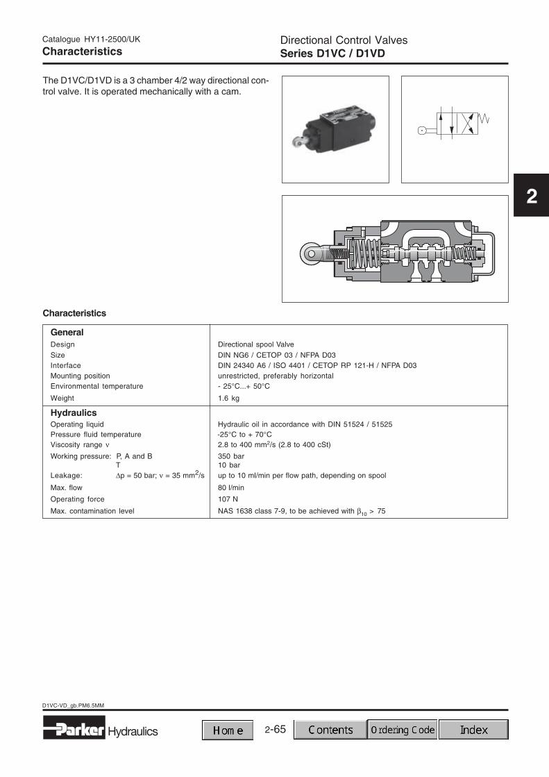
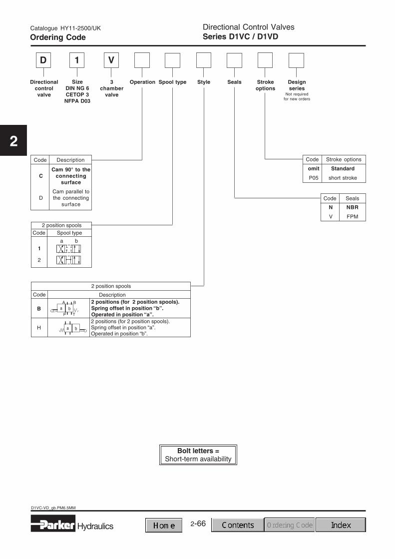
The D1VC/D1VD is a 3 chamber 4/2 way directional con-trol valve. It is operated mechanically with a cam.
GeneralDesign Directional spool Valve
Size DIN NG6 / CETOP 03 / NFPA D03Interface DIN 24340 A6 / ISO 4401 / CETOP RP 121-H / NFPA D03Mounting position unrestricted, preferably horizontalEnvironmental temperature - 25°C...+ 50°C
Weight 1.6 kg
HydraulicsOperating liquid Hydraulic oil in accordance with DIN 51524 / 51525Pressure fluid temperature -25°C to + 70°CViscosity range ν 2.8 to 400 mm2/s (2.8 to 400 cSt)
Working pressure: P, A and B 350 barT 10 bar
Leakage: ∆p = 50 bar; ν = 35 mm2/s up to 10 ml/min per flow path, depending on spool
Max. flow 80 l/min
Operating force 107 N
Max. contamination level NAS 1638 class 7-9, to be achieved with β10 > 75
Characteristics
Characteristics
2-66
D1VC-VD_gb.PM6.5MM
Directional Control ValvesSeries D1VC / D1VD
Hydraulics
Catalogue HY11-2500/UK
2
D V
Directionalcontrolvalve
3chamber
valve
Seals
Code
N NBR
V FPM
Seals
Spool type
1
SizeDIN NG 6CETOP 3
NFPA D03
Ordering Code
Style Designseries
Not requiredfor new orders
Code
omit Standard
P05 short stroke
Stroke optionsCode
Cam 90° to theC connecting
surface
Cam parallel toD the connecting
surface
Description
Strokeoptions
Operation
2-67
2
Hydraulics
D1VC-VD_gb.PM6.5MM
Directional Control ValvesSeries D1VC / D1VD
Catalogue HY11-2500/UK
2
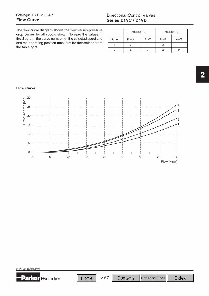
Flow Curve
Position "b" Position "a"
Spool P ->A B->T P->B A->T
1 3 1 3 1
2 4 2 4 2
Flow Curve
The flow curve diagram shows the flow versus pressuredrop curves for all spools shown. To read the values inthe diagram, the curve number for the selected spool anddesired operating position must first be determined fromthe table right.
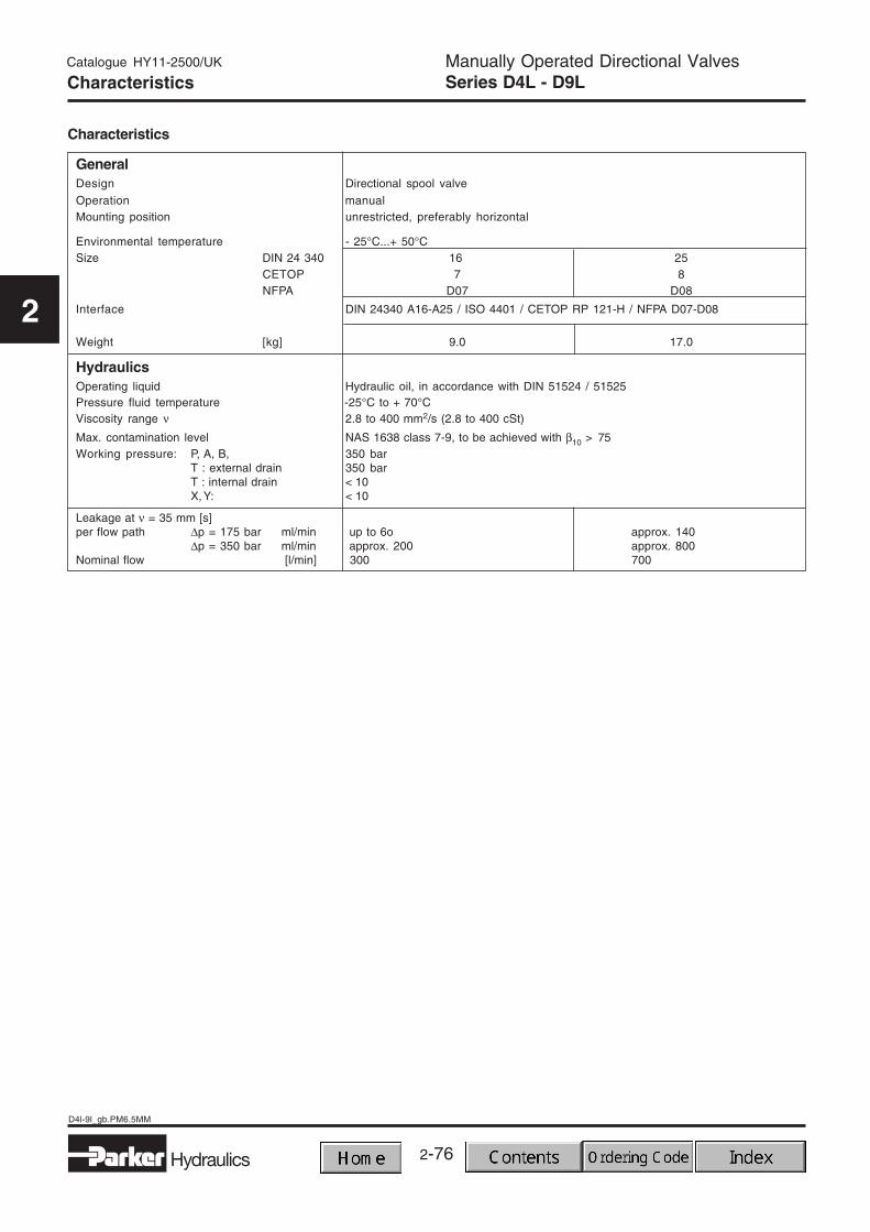
Operation manualMounting position unrestricted, preferably horizontal
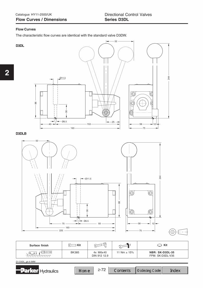
Environmental temperature - 25°C...+ 50°CSize DIN 24 340 16 25
CETOP 7 8NFPA D07 D08
Interface DIN 24340 A16-A25 / ISO 4401 / CETOP RP 121-H / NFPA D07-D08
Weight [kg] 9.0 17.0
HydraulicsOperating liquid Hydraulic oil, in accordance with DIN 51524 / 51525Pressure fluid temperature -25°C to + 70°CViscosity range ν 2.8 to 400 mm2/s (2.8 to 400 cSt)
Max. contamination level NAS 1638 class 7-9, to be achieved with β10 > 75Working pressure: P, A, B, 350 bar
The flow curve diagram shows the flow versus pressuredrop curves for all spools shown. To read the values inthe diagram, the curve number for the selected spool and
desired operating position must first be determined fromthe table below.
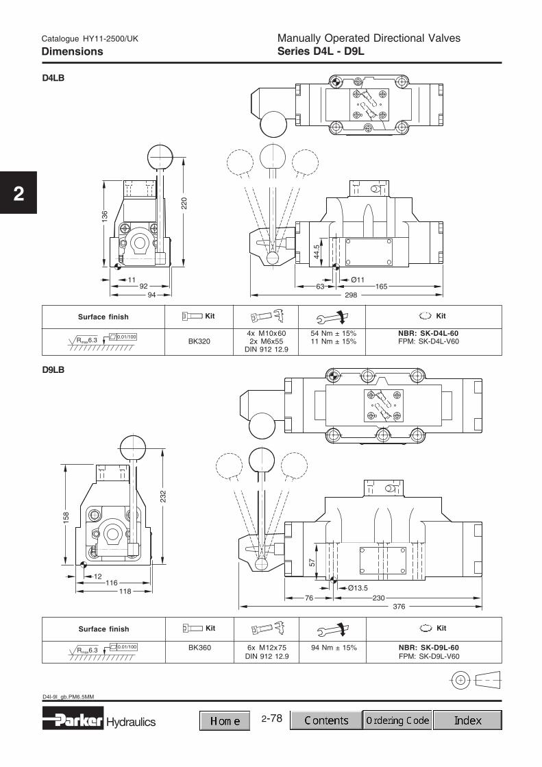
Pilot Operated Directional Control ValvesSeries D3-D11
Catalogue HY11-2500/UK
2
Mounting patterns
Series Size Mounting pattern
DIN NG 10 DIN 24340 design A10D3 CETOP 5 ISO 4401
NFPA D05H CETOP RP121NFPA D05H
DIN NG 16 DIN 24340 design A16D4 CETOP 7 ISO 4401
NFPA D07 CETOP RP121NFPA D07
DIN NG 25 DIN 24340 design A25D8/9 CETOP 8 ISO 4401
NFPA D08 CETOP RP121NFPA D08
DIN NG 32 DIN 24340 design A32D11 CETOP 10 ISO 4401
NFPA D10 CETOP RP121NFPA D10
General
The D31, D41, D81, D91 and D111 are electrical control-led 4/3 or 4/2 way directional control valves. The valvesare pilot operated by an NG6 valve.
Pressure and flow of the pilot oil have a significantinfluence on the response time of the spool in the mainstage.
In order to guarantee a save switching of the spool pleasechoose the appropriate pilot oil supply and drain option.(Spools with a connection P to T need an externalpressure supply or an integral check valve. For spoolswith negative cross-over position are the same optionsrecommended.)
The minimum pilot pressure must be ensured for alloperating condition of the directional valve.
2-80
D3-D11_gb.PM6.5MM
Hydraulics
Pilot Operated Directional Control ValvesSeries D3-D11
Catalogue HY11-2500/UK
2
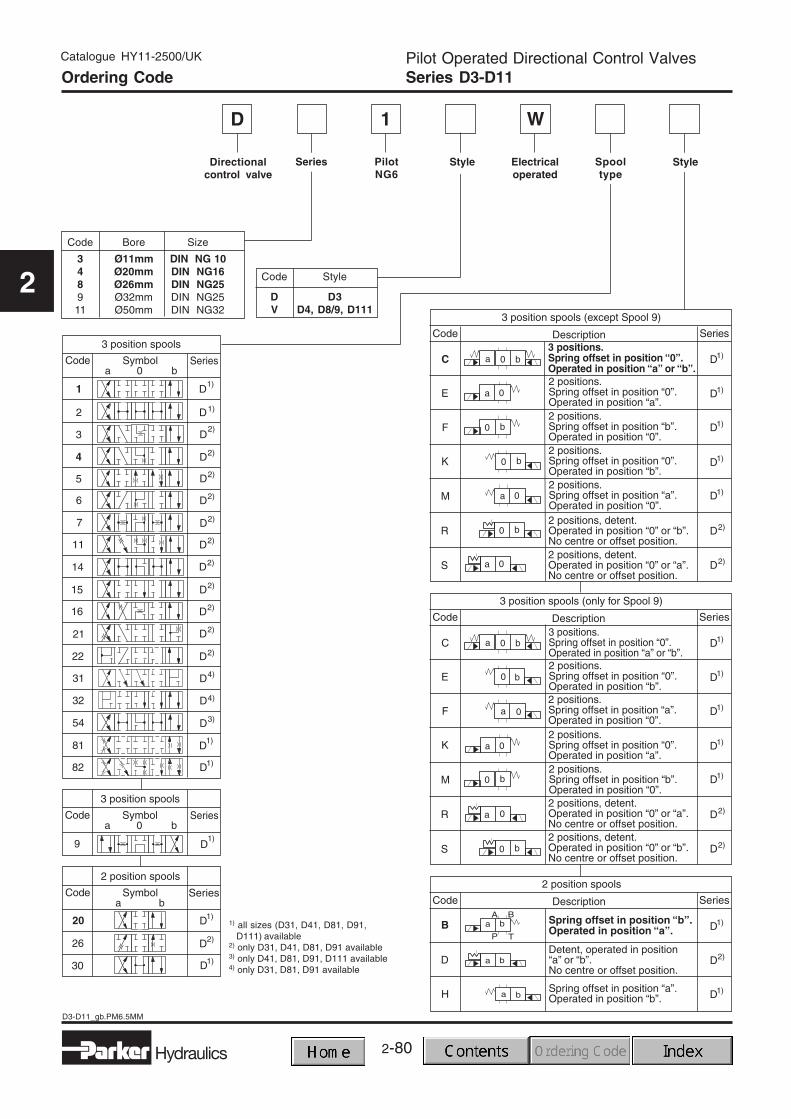
Directionalcontrol valve
D
Ordering Code
Style
Code Bore Size
3 Ø11mm DIN NG 104 Ø20mm DIN NG168 Ø26mm DIN NG259 Ø32mm DIN NG2511 Ø50mm DIN NG32
Code Style
D D3V D4, D8/9, D111
PilotNG6
Series
1 W
Style Electricaloperated
Spooltype
1) all sizes (D31, D41, D81, D91,D111) available
2) only D31, D41, D81, D91 available3) only D41, D81, D91, D111 available4) only D31, D81, D91 available
Catalogue HY11-2500/UK
2-81Hydraulics
D3-D11_gb.PM6.5MM
Pilot Operated Directional Control ValvesSeries D3-D11
2
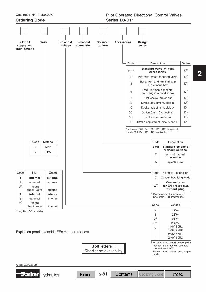
Code Inlet Outlet
1 internal external
2 external external
35) integralcheck valve external
4 internal internal
5 external internal
65) integralcheck valve internal
Designseries
Code Description
omit Standard solenoidwithout options
T without manualoverride
W splash proof
Code Solenoid connection
C Conduit box flying leads
Connector asW7) per EN 175301-803,
without plug
Pilot oilsupply and
drain options
Seals Solenoidvoltage
Solenoidconnection
Solenoidoptions
Accessories
Code Material
N NBR
V FPM
1) all sizes (D31, D41, D81, D91, D111) available2) only D31, D41, D81, D91 available
5) only D41, D81 available
7) Please order plug separately.See page 2-90 accessories.
Code Voltage
6) For alternating current use plug withrectifier, and order with solenoidconnection code W.Please order rectifier plug sepa-rately.
12V=
24V=
98V=
205V=110V 50Hz120V 60Hz
230V 50Hz240V 60Hz
K
J
U6)
G6)
Y
T
Code Description Series
omitStandard valve without
D1)accessories
2 Pilot with press. reducing valve D1)
5Signal light and terminal strip
D1)in a conduit box
6Brad Harrison connector
D1)male plug in a conduit box
7 Pilot choke, meter-out D1)
8 Stroke adjustment, side B D2)
9 Stroke adjustment, side A D2)
56 Option 5 and 6 combined D1)
660 Pilot choke, meter-in D1)
89 Stroke adjustment, side A and B D2)
Explosion proof solenoids EEx me II on request.
Ordering Code
2-82
D3-D11_gb.PM6.5MM
Hydraulics
Pilot Operated Directional Control ValvesSeries D3-D11
Catalogue HY11-2500/UK
2
with ind. pos. control
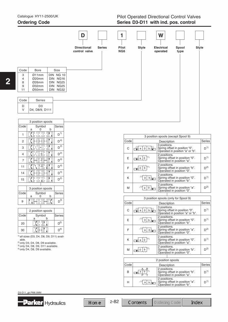
Directionalcontrol valve
D
Style
Code Bore Size
3 Ø11mm DIN NG 104 Ø20mm DIN NG168 Ø26mm DIN NG259 Ø32mm DIN NG25
11 Ø50mm DIN NG32
Code Series
D D3V D4, D8/9, D111
PilotNG6
Series
1
1) all sizes (D3, D4, D8, D9, D11) avail-able.
2) only D3, D4, D8, D9 available.3) only D4, D8, D9, D11 available.4) only D4, D8, D9 available.
W
Style Electricaloperated
Spooltype
Ordering Code
2-83Hydraulics
D3-D11_gb.PM6.5MM
Pilot Operated Directional Control ValvesSeries D3-D11
Catalogue HY11-2500/UK
2
with ind. pos. control
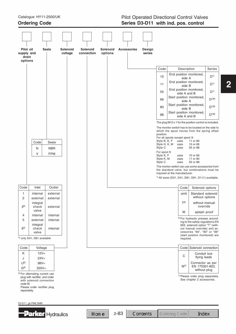
Code Inlet Outlet
1 internal external
2 external external
integral35) check external
valve
4 internal internal
5 external internal
integral65) check internal
valve
Designseries
Code Solenoid options
omit Standard solenoidwithout options
T8) without manualoverride
W splash proof
Code Solenoid connection
Conduit boxC flying leads
Connector as perW7) EN 175301-803,
without plug
Pilot oilsupply and
drainoptions
Seals Solenoidvoltage
Solenoidconnection
Solenoidoptions
Accessories
Code Seals
N NBR
V FPM
The monitor switch has to be located on the side towhich the spool moves from the spring offsetposition.For all spools except spool 9:Style B, E, F uses 11 or 80Style H, K, M uses 10 or 66Style C uses 55 or 88
For spool 9:Style E, F uses 10 or 66Style K, M uses 11 or 80Style C uses 55 or 88
The montor switch can use some accessories fromthe standard valve, but combinations must beinquired at the manufacturer.1) All sizes (D31, D41, D81, D91, D111) available.
5) only D41, D81 available
Code Voltage
6) For alternating current useplug with rectifier, and orderwith solenoid connectioncode W.Please order rectifier plugseparately.
K 12V=
J 24V=
U6) 98V=
G6) 205V=
Code Description Series
10End position monitored,
D1)side A
11End position monitored,
D1)side B
55End position monitored,
D1)side A and B
66Start position monitored,
D1)8)side A
80Start position monitored,
D1)8)side B
88Start position monitored,
D1)8)side A and B
The plug M12 x 1 for the position control is included.
8) For hydraulic presses accord-ing to the safety regulations EN693, solenoid option "T" (with-out manual override) and ac-cessories "66", "80" or "88"(start position monitored) arerequired.
7) Please order plug separately.See chapter 2 accessories.
Ordering Code
2-84
D3-D11_gb.PM6.5MM
Hydraulics
Pilot Operated Directional Control ValvesSeries D3-D11
Catalogue HY11-2500/UK
2
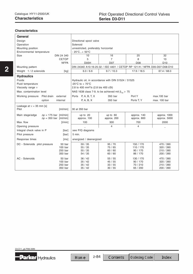
Characteristics
Characteristics
GeneralDesign Directional spool valve
Operation SolenoidMounting position unrestricted, preferably horizontalEnvironmental temperature - 25°C...+ 50°CSize DIN 24 340 10 16 25 32
CETOP 5 7 8 10NFPA D05H D07 D08 D10
Mounting pattern DIN 24340 A10-16-25-32 / ISO 4401 / CETOP RP 121-H / NFPA D05-D07-D08-D10
HydraulicsFluids Hydraulic oil, in accordance with DIN 51524 / 51525Fluid temperature -25°C to + 70°CViscosity range ν 2.8 to 400 mm2/s (2.8 bis 400 cSt)
Max. contamination level NAS 1638 class 7-9, to be achieved mit β10 > 75
Working pressure Pilot drain external Ports P, A, B, T, X 350 bar Port Y max.100 bar
option internal P, A, B, X 350 bar Ports T, Y max. 100 bar
Leakage at ν = 35 mm [s]Pilot [ml/min] 30 at 350 bar
Main stage/adge ∆p = 175 bar [ml/min] up to 20 up to 60 approx. 140 approx. 1000∆p = 350 bar [ml/min] approx. 100 approx. 200 approx. 800 approx. 5000
Max. flow [l/min] 100 300 700 2000
Opening pressure _ 4 4 _
Integral check valve in P [bar] see P/Q diagrams
Pilot pressure [bar] 5 min.
Response times [ms] energized / deenergized
DC - Solenoids pilot pressure 50 bar 59 / 35 95 / 70 150 / 170 470 / 390100 bar 55 / 35 75 / 65 110 / 170 320 / 390250 bar 55 / 35 60 / 60 90 / 170 210 / 390350 bar 54 / 35 60 / 60 86 / 170 200 / 390
Pilot Operated Directional Control ValvesSeries D3-D11
Catalogue HY11-2500/UK
2
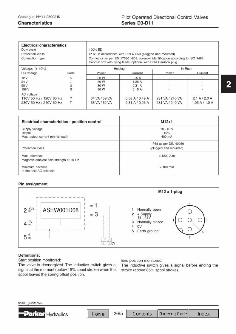
Electrical characteristicsDuty cycle 100% EDProtection class IP 65 in accordance with DIN 40050 (plugged and mounted)Connection type Connector as per EN 175301-803, solenoid identification according to ISO 9461.
Conduit box with flying leads, optional with Brad Harrison plug.
Voltages (± 10%) Holding in RushDC voltage Code Power Current Power Current
12 V K 30 W 2.5 A - -24 V J 30 W 1.25 A - -98 V U 30 W 0.31 A - -198 V G 30 W 0.15 A - -
AC voltage110V 50 Hz / 120V 60 Hz Y 64 VA / 59 VA 0.58 A / 0.49 A 231 VA / 240 VA 2.1 A / 2.0 A230V 50 Hz / 240V 60 Hz T 68 VA / 62 VA 0.31 A / 0.26 A 231 VA / 240 VA 1.05 A / 1.0 A
Electrical characteristics - position control M12x1
Supply voltage 18 - 42 VRipple 10%Max. output current (ohmic load) 400 mA
IP65 as per DIN 40050Protection class (plugged and mounted)
Max. tolerance < 1200 A/mmagnetic ambient field strength at 50 Hz
Minimum distance > 100 mmto the next AC solenoid
Definitions:Start position monitored:The valve is deenergized. The inductive switch gives asignal at the moment (below 15% spool stroke) when thespool leaves the spring offset position.
Pin assignment
End position monitored:The inductive switch gives a signal before ending thestroke (above 85% spool stroke).
1 Normally open2 + Supply
18...42V3 Normally closed4 0V5 Earth ground
M12 x 1-plug
Characteristics
2-86
D3-D11_gb.PM6.5MM
Hydraulics
Pilot Operated Directional Control ValvesSeries D3-D11
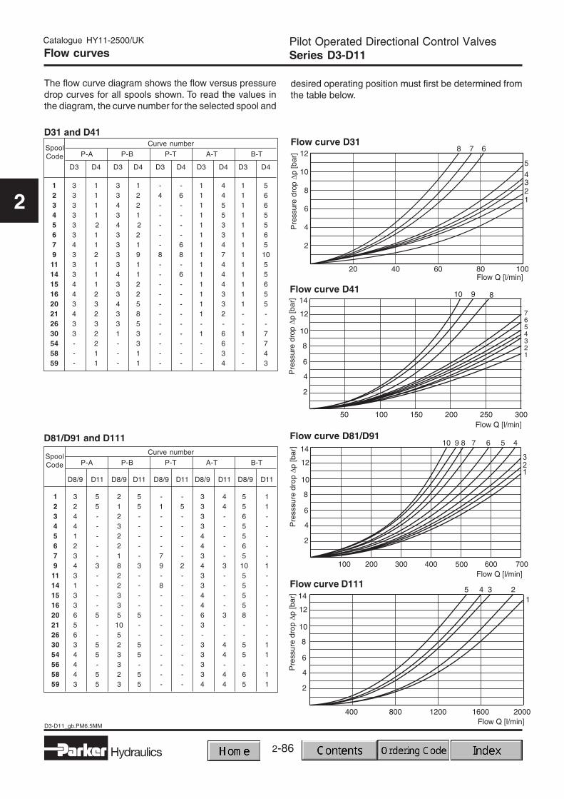
The flow curve diagram shows the flow versus pressuredrop curves for all spools shown. To read the values inthe diagram, the curve number for the selected spool and
desired operating position must first be determined fromthe table below.
2-87Hydraulics
D3-D11_gb.PM6.5MM
Pilot Operated Directional Control ValvesSeries D3-D11
Catalogue HY11-2500/UK
2
Integral Check Valve / Pilot Oil Options
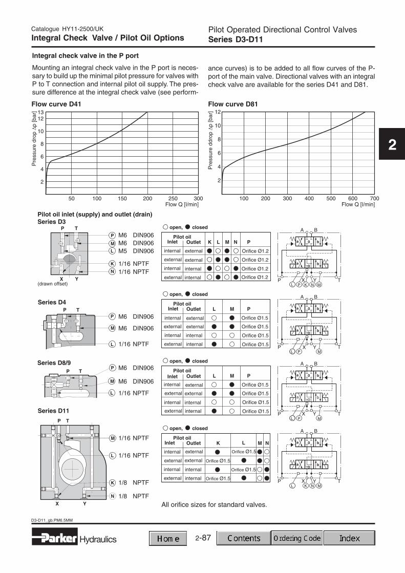
Integral check valve in the P port
Mounting an integral check valve in the P port is neces-sary to build up the minimal pilot pressure for valves withP to T connection and internal pilot oil supply. The pres-sure difference at the integral check valve (see perform-
ance curves) is to be added to all flow curves of the P-port of the main valve. Directional valves with an integralcheck valve are available for the series D41 and D81.
Flow curve D81Flow curve D41
All orifice sizes for standard valves.
2-88
D3-D11_gb.PM6.5MM
Hydraulics
Pilot Operated Directional Control ValvesSeries D3-D11
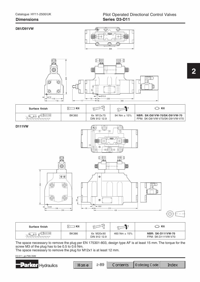
The space necessary to remove the plug per EN 175301-803, design type AF is at least 15 mm. The torque for thescrew M3 of the plug has to be 0.5 to 0.6 Nm.The space necessary to remove the plug for M12x1 is at least 12 mm.
2-90
Zubehör_gb.PM6.5MM
Hydraulics
Directional Control ValvesAccessories
Catalogue HY11-2500/UK
2
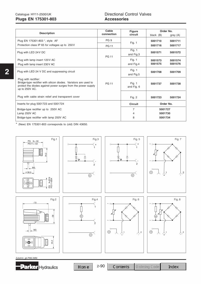
DescriptionOrder No.Figure
circuitCable
connection
5001710 5001711
5001716 5001717
Plug EN 175301-803 *, style AF
Protection class IP 65 for voltages up to 250V
5001571 5001572Plug with LED 24V DC
Plug with lamp insert 120V AC
Plug with lamp insert 230V AC
Plug with LED 24 V DC and suppressing circuit
Plug with cable strain relief and transparent cover
Inserts for plug 5001723 and 5001724
Plug with rectifier:Bridge-type rectifier with silicon diodes. Varistors are used toprotect the diodes against power surges from the power supplyup to 250V AC.
Fig. 1and Fig. 6
5001737 5001738
Fig. 1
and Fig.55001708 5001709
5001573 50015745001575 5001576
PG 11
Fig. 1
Fig. 1
and Fig.4
Fig. 1
and Fig.3
Fig. 2
PG 9
PG 11
PG 11
5001723 5001724
black (B) grey (A)
Bridge-type rectifier up to 250V AC 7 5001727Lamp 250V AC 4 5001730
Bridge-type rectifier with lamp 250V AC 8 5001734
Order No.Circuit
Plugs EN 175301-803
* (New) EN 175301-803 corresponds to (old) DIN 43650.
2-91
2
Hydraulics
Zubehör_gb.PM6.5MM
Directional Control ValvesAccessories
Catalogue HY11-2500/UK
2
Conduit boxes
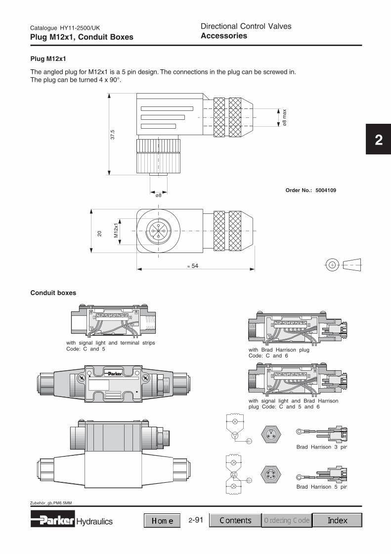
Plug M12x1, Conduit Boxes
Plug M12x1
The angled plug for M12x1 is a 5 pin design. The connections in the plug can be screwed in.The plug can be turned 4 x 90° .
EN plug without manual EN plug with 210bar tank EN plug without manualVoltage Voltage EN plug override (Code "T") pressure (Code "H") EN plug override (Code "T")Volt/Hertz Code D3W / D3DW1) D3W / D3DW1) D3W / D3DW1) D3W / D3DW1) D3W / D3DW1)
12V= K KW-30 KWT-30 KW-30 KW-30 KWT-3024V= J JW-30 JWT-30 JW-30 JW-30 JWT-3098V= U UW-30 UWT-30 UW-30 UW-30 UWT-30205V= G GW-30 GWT-30 GW-30 GW-30 GWT-30
110V/50Hz,120V/60Hz Y YW-30 - YWH-30 YW-30 -230V/50Hz, 240V/60Hz
T TW-30 - TWH-30 TW-30 -
For D3W / D3DW
1) D3DW only with DC voltagesOther solenoid and coil kits on request.A solenoid kit contains: tube, coil, retainer and seals for the solenoid.A coil kit contains: coil, retainer and seals for the coil.