36
MS35 HYDRAULIC MOTORS T E C H N I C A L C A T A L O G
M S 35H Y D R A U LIC M O TO R S
T E C H N I C A L C A T A L O G
Modular hydraulic motors MS35 POCLAIN HYDRAULICS
31/08/2016 2
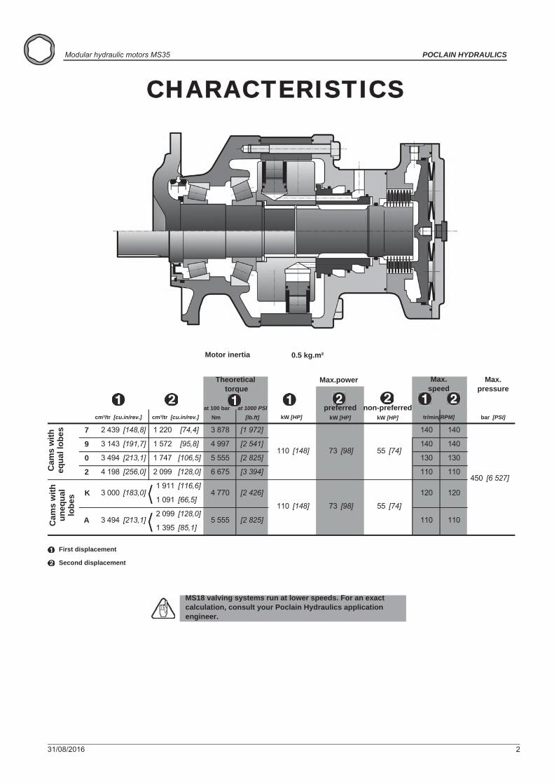
CHARACTERISTICS
Motor inertia 0.5 kg.m²
MS18 valving systems run at lower speeds. For an exact calculation, consult your Poclain Hydraulics application engineer.
7 2 439 [148,8] 1 220 [74,4] 3 878 [1 972] 140 140
9 3 143 [191,7] 1 572 [95,8] 4 997 [2 541] 140 140
0 3 494 [213,1] 1 747 [106,5] 5 555 [2 825] 130 130
2 4 198 [256,0] 2 099 [128,0] 6 675 [3 394] 110 110
1 911 [116,6]
1 091 [66,5]
2 099 [128,0]
1 395 [85,1]
110 [148]
450
[2 825]
[2 426]
110 [148] [74]
120
110
[6 527]
55 [74]73 [98]
110
120
73 [98] 55
A 3 494 [213,1] 5 555
K 3 000 [183,0] 4 770
Cam
s w
ith
equa
l lob
es
Theoretical torque
at 100 bar at 1000 PSI Nm [lb.ft]
Max.speed
tr/min[RPM]
Max.power
kW [HP]cm³/tr [cu.in/rev.]cm³/tr [cu.in/rev.]preferred
kW [HP]non-preferred
kW [HP]
First displacement
Second displacement
Max. pressure
bar [PSI]
Cam
s w
ith
uneq
ual
lobe
s

31/08/2016 3
CONTENT
Valv
ing
syst
ems
and
hydr
obas
esO
ptio
nsB
rake
Shaf
t mot
orW
heel
mot
or
Mod
ular
ity a
ndM
odel
cod
e
POCLAIN HYDRAULICS Modular hydraulic motors MS35
MODULARITY 4MODEL CODE 6
WHEEL MOTOR 9Dimensions for standard (1110) 1-displacement motor 9Dimensions for standard (1110) 2-displacement motor 9Support types 10Studs 10Load curves 11Load curves (continued) 13
SHAFT MOTOR 15Dimensions for standard (2A50) 1-displacement motor 15Dimensions for standard (2A50) 2-displacement motor 15Support types 16 Cylindrical bushed coupling 17
VALVING SYSTEMS AND HYDROBASES 19Dimensions for 1-displacement valving 19Hydraulic connections 24Efficiency 26
BRAKES 27Rear brake 27Rear brake 28Rear brake 29C27TM combined brake 30Drum brake (432 x 102) 31
OPTIONS 33

4 31/08/2016
Modular hydraulic motors MS35 POCLAIN HYDRAULICS
MODUL
FT30
1
C
1 2
D
3 1 2
F
3
M 3 5S
Torq
ue m
odul
e
Wheel motor
Shaft motor
* MS18 sub-assembly
MODULARITY
31/08/2016 5
POCLAIN HYDRAULICS Modular hydraulic motors MS35
Valv
ing
syst
ems
and
hydr
obas
esO
ptio
nsB
rake
Shaf
t mot
orW
heel
mot
or
Mod
ular
ity a
ndM
odel
cod
e
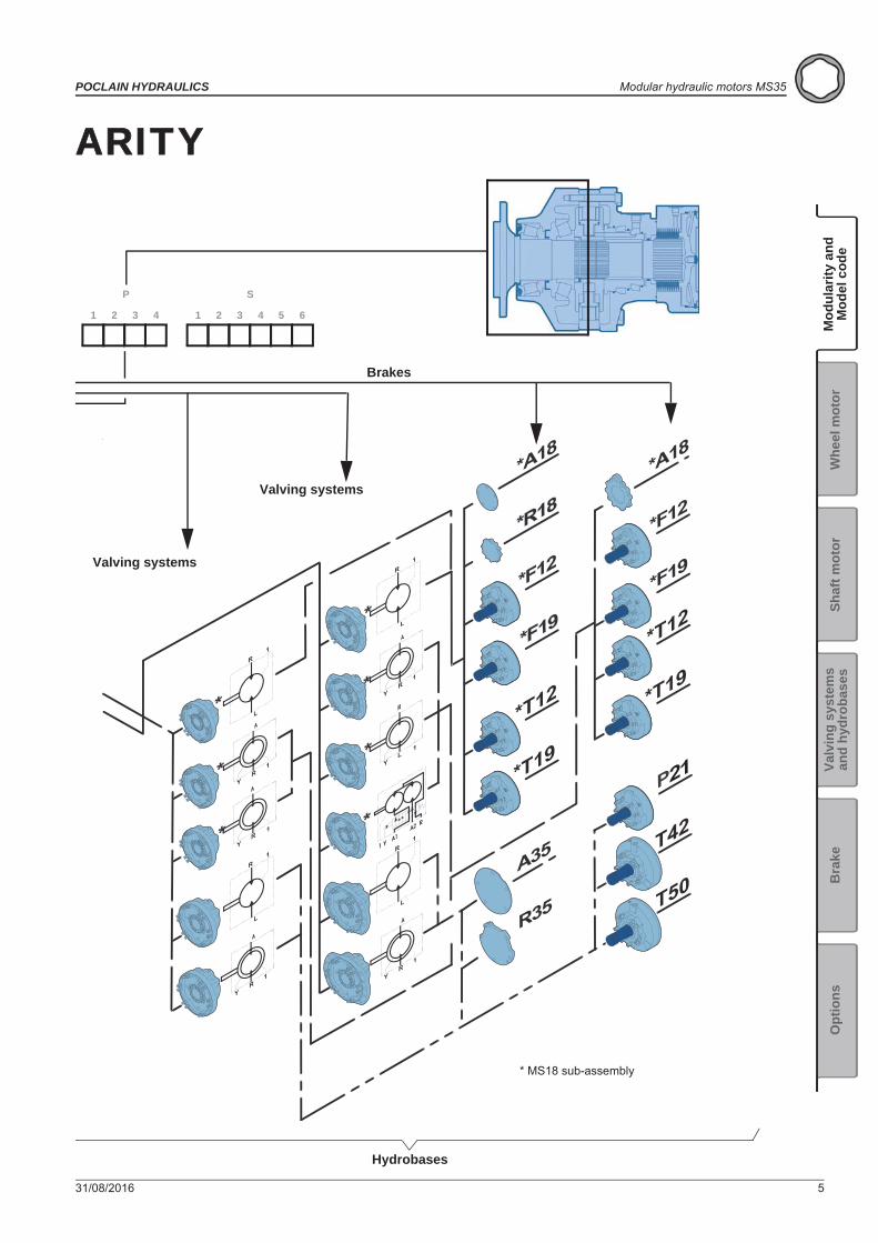
ARITY
21
1 2
P
3 4 1 2
S
3 4 5 6
Brakes
Valving systems
Valving systems
Hydrobases
* MS18 sub-assembly
6 31/08/2016
Modular hydraulic motors MS35 POCLAIN HYDRAULICS
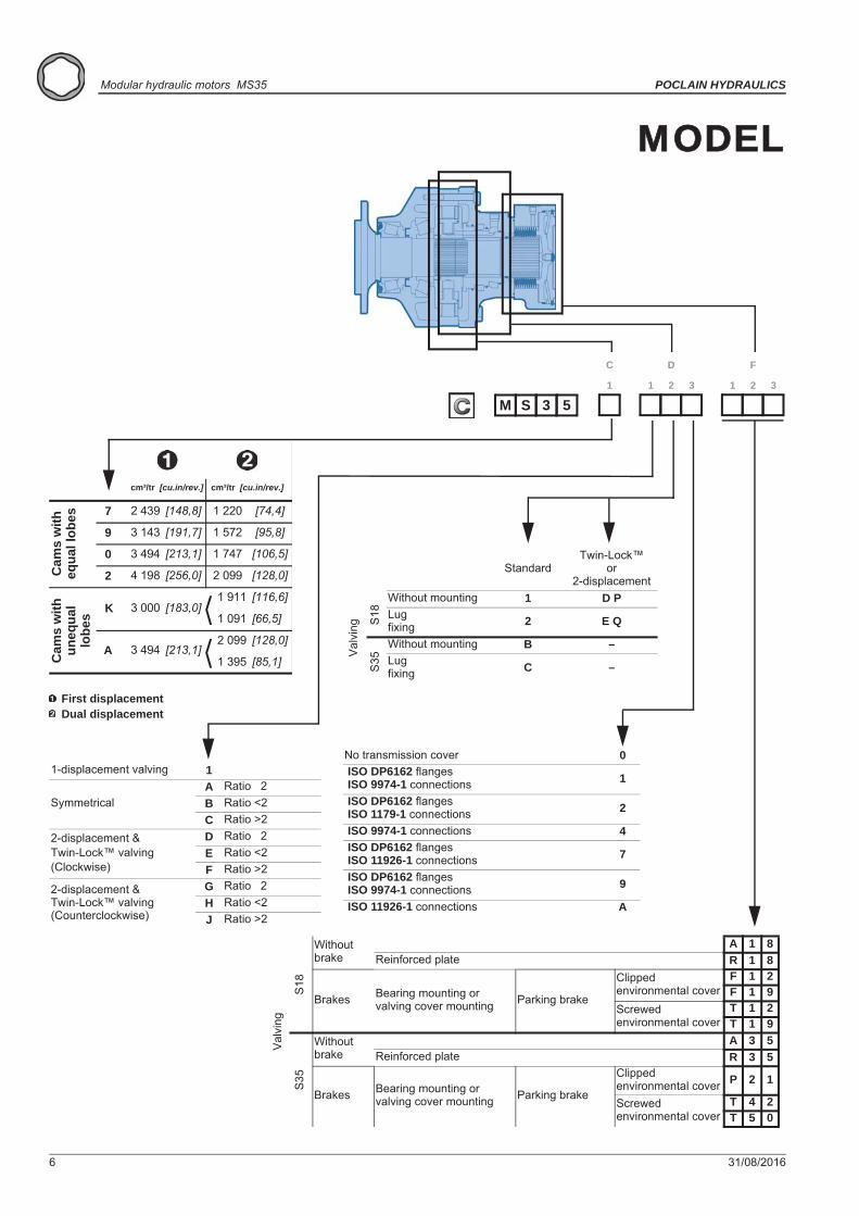
MODEL
No transmission cover 0 ISO DP6162 flanges ISO 9974-1 connections 1
ISO DP6162 flanges ISO 1179-1 connections 2
ISO 9974-1 connections 4 ISO DP6162 flanges ISO 11926-1 connections 7
ISO DP6162 flanges ISO 9974-1 connections 9
ISO 11926-1 connections A
Val
ving
S18
Without brake
A 1 8Reinforced plate R 1 8
Brakes Bearing mounting or valving cover mounting Parking brake
Clipped environmental cover
F 1 2F 1 9
Screwed environmental cover
T 1 2T 1 9
S35
Without brake
A 3 5Reinforced plate R 3 5
Brakes Bearing mounting or valving cover mounting Parking brake
Clipped environmental cover P 2 1
Screwed environmental cover
T 4 2T 5 0
1-displacement valving 1
Symmetrical A Ratio 2B Ratio <2C Ratio >2
2-displacement &Twin-Lock™ valving(Clockwise)
D Ratio 2E Ratio <2F Ratio >2
2-displacement &Twin-Lock™ valving(Counterclockwise)
G Ratio 2H Ratio <2J Ratio >2
StandardTwin-Lock™
or2-displacement
Without mounting 1 D P Lug fixing 2 E Q
Without mounting B –Lug fixing C –
Val
ving
S18
S35
7 2 439 [148,8] 1 220 [74,4]
9 3 143 [191,7] 1 572 [95,8]
0 3 494 [213,1] 1 747 [106,5]
2 4 198 [256,0] 2 099 [128,0]
1 911 [116,6]
1 091 [66,5]
2 099 [128,0]
1 395 [85,1]
K 3 000 [183,0]
A 3 494 [213,1]
Cam
s w
ith
equa
l lob
esC
ams
with
un
equa
l lo
bes
cm³/tr [cu.in/rev.]cm³/tr [cu.in/rev.]
First displacementDual displacement
1
C
1 2
D
3 1 2
F
3
M 3 5S
MODEL CODE

31/08/2016 7
POCLAIN HYDRAULICS Modular hydraulic motors MS35
Valv
ing
syst
ems
and
hydr
obas
esO
ptio
nsB
rake
Shaf
t mot
orW
heel
mot
or
Mod
ular
ity a
ndM
odel
cod
e
CODE
0 Without bearing support1 Without mounting2 Lug mounting6 Motor torqueF Brake C27TM with chasis fixation
Without shaft 010 x Ø24 on Ø335 18 x Ø22 on Ø275 38 x Ø17.5 on Ø235 412 x Ø22 on Ø275 510 x Ø24 on Ø335(for studs length of 65 mm) T*
10 x Ø24 on Ø225 6Support without drum brake G
Drum brake (432 x 102) Mineral KDOT L
For male shaft bearing support A*Standard for C27TM brake
Without Options or Adaptations 0Fluorinated elastomer seals 1T4 Speed sensor installed 2Brake environmental cover without plug 3Drainage 5Industrial bearing support 6Diamond™ 7Predisposition for speed sensor 8Hollow shaft ADrain on the bearing support BReinforced sealing ESpecial wheel rim mounting GSurface heat treatment of the shaft JTR Speed sensor installed S
Without studs 1With studs + nuts 2With studs 3M threaded holes 4
Male shaftsNF E 22141 splines 1DIN 5480 splines 5Female shaft for bushing L
1 2
P
3 4 1 2
S
3 4 5 6
Drum brakeWithout cable 4
ConnectionM14x1.5Right-hand cable outlet 5
Left-hand cable outlet 6
8 31/08/2016
Modular hydraulic motors MS35 POCLAIN HYDRAULICS
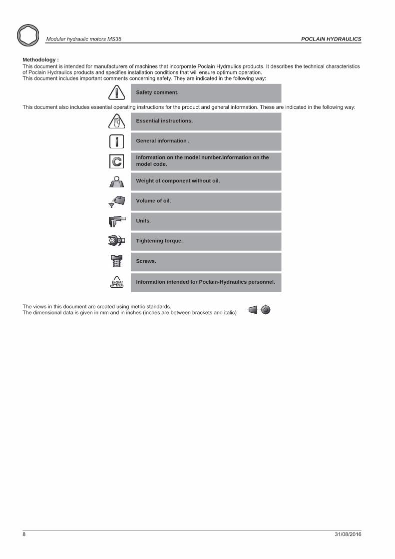
Methodology :This document is intended for manufacturers of machines that incorporate Poclain Hydraulics products. It describes the technical characteristics of Poclain Hydraulics products and specifies installation conditions that will ensure optimum operation. This document includes important comments concerning safety. They are indicated in the following way:
This document also includes essential operating instructions for the product and general information. These are indicated in the following way:
The views in this document are created using metric standards. The dimensional data is given in mm and in inches (inches are between brackets and italic)
Safety comment.
Essential instructions.
General information .
Information on the model number.Information on the model code.
Weight of component without oil.
Volume of oil.
Units.
Tightening torque.
Screws.
Information intended for Poclain-Hydraulics personnel.

31/08/2016 9
POCLAIN HYDRAULICS Modular hydraulic motors MS35
Valv
ing
syst
ems
and
hydr
obas
esO
ptio
nsB
rake
Shaf
t mot
orW
heel
mot
or
Mod
ular
ity a
ndM
odel
cod
e
WHEEL MOTOR
Also see 'Valving systems and hydrobases' section (thumbnail opposite).
209 kg [460 lb] 269 kg [592 lb]
5,00 L [300 cu.in] 4,00 L [240 cu.in]
Dimensions for standard (1110) 1-displacement motor
209 kg [460 lb] 269 kg [592 lb]
5,00 L [300 cu.in] 4,00 L [240 cu.in]
Dimensions for standard (1110) 2-displacement motor
B 108,5 [4,27] 148,0 [5,83] 157,5 [6,20]C Ø280 [11,02 dia.] Ø375 [14,76 dia.] Ø375 [14,76 dia.]D 57 [2,24] 63,5 [2,50] 63,5 [2,50]E 138,5 [5,45] 183,5 [7,22] 183,5 [7,22]
Also see ’Brakes’ section(thumbnail opposite).
P 12 T 24 T 05

10 31/08/2016
Modular hydraulic motors MS35 POCLAIN HYDRAULICS
Support types
Studs
See generic installation motors N°801478197L.
M 3 5S1
C
1 2
D
3 1 2
F
3 1 2
P
3 4 1 2
S
3 4 5 6
A B C D E N L
mm [in] mm [in] mm [in] mm [in] mm [in] mm [in] mm [in]
1 1 1 01 4
1 3 1 01 4
1 4 1 01 4
1 5 1 01 4
1 6 1 01 4 [6,92 dia.] [8,86 dia.] [10,87 dia.] [11,10] [13,15 dia.] [0,94 dia.] [0,59]
2 3 P
[5,99 dia.] [9,25 dia.] [11,02 dia.] -15Ø 152,27 Ø 235 Ø 280 213
[8,39] [13,15 dia.] [0,69 dia.] [0,59]Ø 334 Ø 17,5
Ø 334
Ø 334 Ø 22
2 3 P
Ø 175,7 Ø 225 Ø 276 15Ø 2410 x
M22x1.5
282
[11,10] [13,15 dia.] [0,87 dia.] [0,55](8+4) x
M20x1.5
142 3 P
[8,69 dia.] [10,83 dia.] [12,36 dia.]Ø 220,7 Ø 275 Ø 314 282
[11,10] [13,15 dia.] [0,87 dia.] [0,55]2 3 P
[8,69 dia.] [10,83 dia.] [12,36 dia.]Ø 334 Ø 22 8 x
M20x1.5
14Ø 220,7 Ø 275 Ø 314 282
[13,15 dia.][12,56][15,20 dia.][13,19 dia.]2 3 P
Ø 335 Ø 386 319[11,06 dia.]
Ø 280,8 Ø 334 Ø 24 10 x M22x1.5
24[0,94][0,94 dia.]
Wheel rim mountings
(1) * (2) *mm [in] mm [in] mm [in] mm [in] N.m [lb.ft] N.m [lb.ft]
M16 x 1.5 50 [1,97] 21,0 [0,83] 300 [221,3] 380 [280,3]M20 x 1.5 60 [2,36]M20 x 1.5 70 [2,76]M22 x 1.5 64 [2,52]M22 x 1.5 80 [3,15]M16 x 1.5 - - 23,0 [0,91] 10,9 250 [184,4] 315 [232,3]
25,0 [0,98]
26,0
[442,5]
695
P C min. D
5 [0,20] 12,9 600 770 [567,9]
1 050 [774,4][1,02] [512,6]
(*) The tightening torques are given for the indicated loads.(1) Wheel rim : Suggested tightening torque for wheel rim mountings (Re steel disc > 240 N/mm² [>34 800 PSI]).(2) Standard : Suggested tightening torque in other cases (Re steel flange 360 > N/mm² [>52 215 PSI])(3) In case of bearings 8P30 and 8Q30 : Poclain recommends to use the flanged nuts with tightening torque = 900 Nm.
Class
Various studs
Screws
C min. C max.

31/08/2016 11
POCLAIN HYDRAULICS Modular hydraulic motors MS35
Valv
ing
syst
ems
and
hydr
obas
esO
ptio
nsB
rake
Shaf
t mot
orW
heel
mot
or
Mod
ular
ity a
ndM
odel
cod
e
Load curves
Permissible radial loads Service life of bearingsTest conditions : Test conditions : Static : 0 tr/min [0 RPM] 0 bar [0 PSI] L : Millions B10 revolutions at 150 bars (average
pressure), with 25 cSt fluid, code 0 displacement, without axial load.
Dynamic : 0 tr/min [ 0 RPM], code 0 displacement, without axial load at max. torque
1 1 1 01 2 3 4
P
1 3 1 01 2 3 4
P
1 5 1 01 2 3 4
P
1 6 1 01 2 3 4
P
The service life of the components is influenced by the pressure.You must check that the combination of forces applied (Axial load / Radial load) is compatible with the permissible loads for the components, and that the resulting service lives of these components complies with the application's specifications. For an accurate calculation, consult your Poclain Hydraulics application engineer.
kN
in
lbf
mm
12 31/08/2016
Modular hydraulic motors MS35 POCLAIN HYDRAULICS
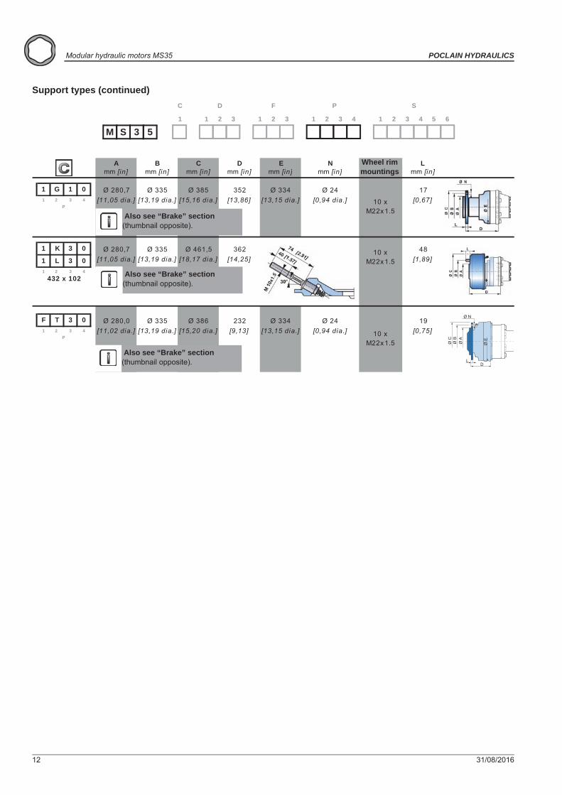
Support types (continued)
M 3 5S1
C
1 2
D
3 1 2
F
3 1 2
P
3 4 1 2
S
3 4 5 6
A B C D E N Lmm [in] mm [in] mm [in] mm [in] mm [in] mm [in] mm [in]
1 G 1 01 4
1 K 3 0
1 L 3 0 [11,05 dia.] [18,17 dia.]
1 4
F T 3 01 4 10 x
M22x1.5
192 3
P[11,02 dia.] [0,75][13,19 dia.] [15,20 dia.] [9,13] [13,15 dia.]
Ø 280,0[0,94 dia.]
Ø 335
[13,19 dia.]
Ø 334 Ø 24Ø 335 Ø 386
17[0,67]
432 x 102
Ø 385 352 Ø 334
2 3
48[1,89]
Ø 280,7 Ø 335 Ø 461,5 362 10 x M22x1.5
10 x M22x1.5
2 3 P
[11,05 dia.] [13,19 dia.] [15,16 dia.] [13,86] [13,15 dia.] [0,94 dia.]Ø 24Ø 280,7
232
[14,25]
Also see “Brake” section(thumbnail opposite).
Wheel rim mountings
Also see “Brake” section(thumbnail opposite).
Also see “Brake” section(thumbnail opposite).
Ø EØ A
Ø B
Ø C
LD
Ø N
31/08/2016 13
POCLAIN HYDRAULICS Modular hydraulic motors MS35
Valv
ing
syst
ems
and
hydr
obas
esO
ptio
nsB
rake
Shaf
t mot
orW
heel
mot
or
Mod
ular
ity a
ndM
odel
cod
e
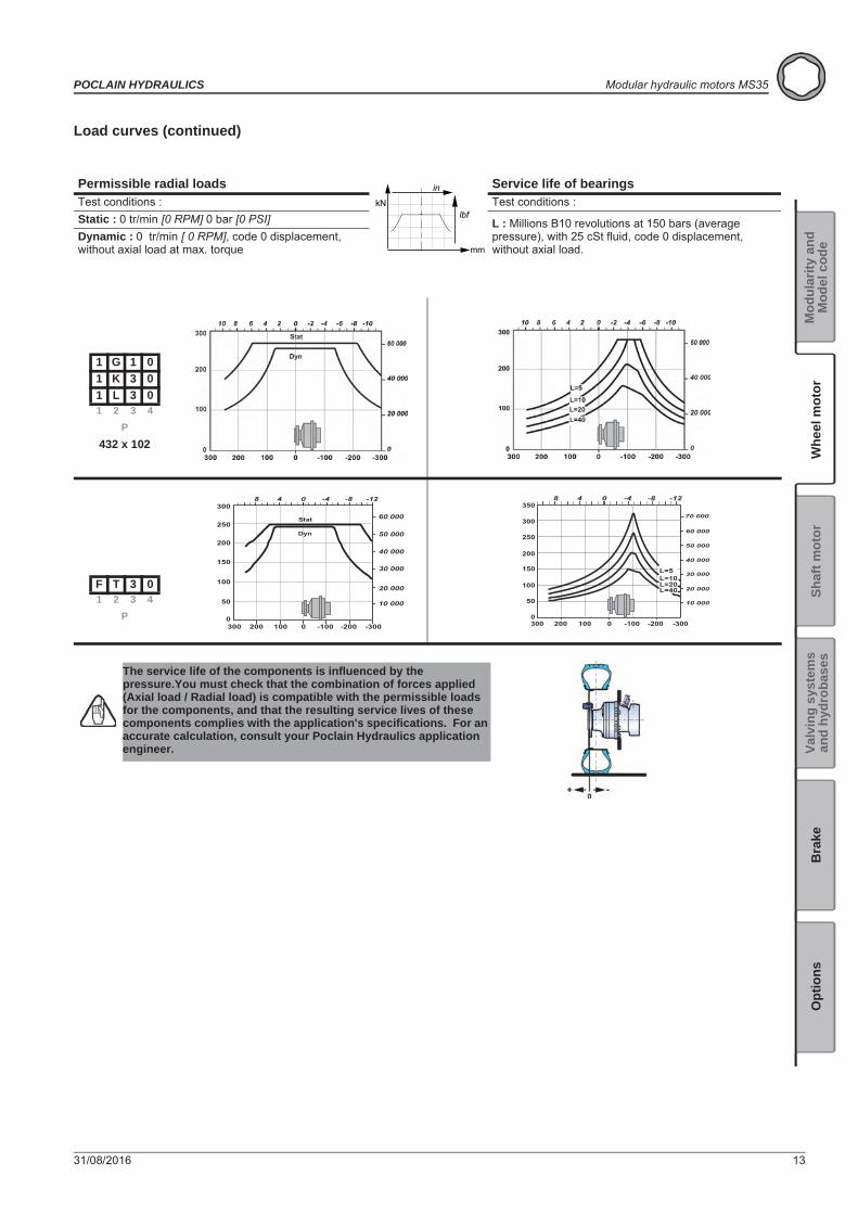
Load curves (continued)
Permissible radial loads Service life of bearingsTest conditions : Test conditions : Static : 0 tr/min [0 RPM] 0 bar [0 PSI] L : Millions B10 revolutions at 150 bars (average
pressure), with 25 cSt fluid, code 0 displacement, without axial load.
Dynamic : 0 tr/min [ 0 RPM], code 0 displacement, without axial load at max. torque
1 G 1 01 K 3 01 L 3 01 2 3 4
P
432 x 102
F T 3 01 2 3 4
P
The service life of the components is influenced by the pressure.You must check that the combination of forces applied (Axial load / Radial load) is compatible with the permissible loads for the components, and that the resulting service lives of these components complies with the application's specifications. For an accurate calculation, consult your Poclain Hydraulics application engineer.
kN
in
lbf
mm
200 0 -200
8 4 0 -4 -8 -12
50
100
150
200
250
0
10 000
20 000
30 000
40 000
50 000
-300-100100300
30060 000
200 -2000
50
100
150
200
250
300
0
10 000
20 000
30 000
40 000
50 000
60 000
8 4 0 -4 -8 -12
L=5L=10L=20L=40
-300-100100300
35070 000

14 31/08/2016
Modular hydraulic motors MS35 POCLAIN HYDRAULICS

31/08/2016 15
POCLAIN HYDRAULICS Modular hydraulic motors MS35
Valv
ing
syst
ems
and
hydr
obas
esO
ptio
nsB
rake
Shaf
t mot
orW
heel
mot
or
Mod
ular
ity a
ndM
odel
cod
e
SHAFT MOTOR
Also see 'Valving systems and hydrobases' section (thumbnail opposite).
188 kg [414 lb] 248 kg [546 lb]
5,00 L [300 cu.in] 4,00 L [240 cu.in]
Dimensions for standard (2A50) 1-displacement motor
198 kg [436 lb] 152 kg [334 lb]
3,00 L [180 cu.in] 2,50 L [150 cu.in]
Dimensions for standard (2A50) 2-displacement motor
B 108,5 [4,27] 148,0 [5,83] 157,5 [6,20]C Ø280 [11,02 dia.] Ø375 [14,76 dia.] Ø375 [14,76 dia.]D 57 [2,24] 63,5 [2,50] 63,5 [2,50]E 138,5 [5,45] 183,5 [7,22] 183,5 [7,22]
Also see ’Brakes’ section(thumbnail opposite).
P 12 T 24 T 05
16 31/08/2016
Modular hydraulic motors MS35 POCLAIN HYDRAULICS
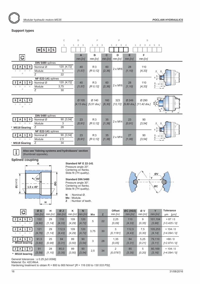
Support types
Splined coupling
General tolerances : ± 0.25 [±0.0098].Material: Ex: 42CrMo4.Hardening treatment to obtain R = 800 to 900 N/mm² [R = 116 030 to 130 533 PSI].
Also see 'Valving systems and hydrobases' section (thumbnail opposite).
M 3 5S1
C
1 2
D
3 1 2
F
3 1 2
P
3 4 1 2
S
3 4 5 6
Amm [in]
Bmm [in]
Cmm [in]
Dmm [in]
Emm [in]
Fmm [in]
2 A 5 0 120 [4,72]1 4 5
Z 22
2 A 1 0 120 [4,72]1 4 3,75
Z 30
6 A L 01 4
2 A 5 0 90 [3,54]1 4 3
Z 28
2 A 1 0 90 [3,54]1 4 2.5
Z 34
27 90
23
R 32 3
P[0,91] [R 0,12] [3,54]
2 3 P
[0,91] [R 0,12] [1,38]
[1,38]35 2 x M14
[1,06]23
Ø 249 Ø 290323Ø 105 Ø 140 160[9,80 dia.] [11,42 dia.][12,72]
23 R 3 352 x M14
90[0,91] [3,54]
2 3 P
[4,13 dia.] [5,51 dia.] [6,30]
282 x M16 [1,10]
28[1,10]2 x M16
2 3 P
R 3[R 0,12]
60[2,36][1,57]
40
40 R 3 602 3
P[1,57] [2,36][R 0,12]
110[4,33]
110[4,33]
DIN 5480 splinesNominal ØModule
NF E22-141 splinesNominal ØModule
DIN 5480 splinesNominal ØModule
NF E22-141 splinesNominal ØModule
* MS18 bearing
* MS18 bearing
Standard NF E 22-141Pressure angle 20°.Centering on flanks.Slide fit (7H quality).
Standard DIN 5480Pressure angle 30°.Centering on flanks.Slide fit (7H quality).
N : Nominal Ø.Mo : Module.Z : Number of teeth.
ØVY
ØC
K
H
1.5 x 45°
45°
ØG
ØJ
H10
Ø G H Ø J K N ØC (H10) Ø V Ymm [in] mm [in] mm [in] mm [in] mm [in] Mo Z mm [in] mm [in] mm [in] mm [in] μm [μin]
2 A 5 01 4
2 A 1 01 4
2 A 5 0
2 A 1 0[+4.094 / 0]
+ 104 / 0[3,58] [1,10] [3,35] [3,50] [3,54] [0,0787]
2 5[3,16]80,169
[3,35] [0,20]
[3,11] [+2.874 / 0]
91 28 85,0 89 902,5 34
85
5,2528
1,35 84[3,31] [0,21][3,50] [3,54] [0,05]
390
[3,60] [0,98] [3,31]
112,5
79,110 +68 / 091,5 25 84 89
7,5112,5[4,43]
2259
[0,35]2,25
[0,09] [4,33]110
[4,14][0,30] [+4.094 / 0]105,253
+ 87 / 0[+3.425 / 0]
+ 104 / 0
[3,98]101,104
[0,1181]109
[4,29]120 3
[4,72]3,75 30
110 120109[4,80]
122[4,72][4,29][4,33]2 3
P
29[1,14]
121 292 3
P[4,76] [1,14] [4,43]
Offset Tolerance
* MS18 bearing
* MS18 bearing

31/08/2016 17
POCLAIN HYDRAULICS Modular hydraulic motors MS35
Valv
ing
syst
ems
and
hydr
obas
esO
ptio
nsB
rake
Shaf
t mot
orW
heel
mot
or
Mod
ular
ity a
ndM
odel
cod
e
Cylindrical bushed coupling
Load curves
Permissible radial loads Service life of bearingsMax. permissible loads: 0 tr/min [0 RPM]; 0 bar [0 PSI] Test conditions : Continuous permissible loads: > 0 tr/min [> 0 RPM]; 275 bar [3 988 PSI].
L : Millions B10 revolutions at 150 bars (average pressure), with 25 cSt fluid, code 0 displacement, without axial load.
2 A 5 02 A 1 01 2 3 4
P
6 A L 01 2 3 4
P
2 A 5 02 A 1 01 2 3 4
P
A B C Dmm [in] mm [in] mm [in] mm [in]
6 A L 01 42 3
P
95[3,74]
0,5[0,0197][4,13 dia.]
Ø 105 10[0,394]
R min. : 640 N/mm² [132 800 PSI]
B
A
C
D
kN
in
lbf
mm
mm [in] mm [in]
2 A 1 0 2 A 1 0
2 A 5 0 2 A 5 0
6 A L 0
129 [5,08] 106,5 [4,193]
38,75 [1,53]
GG
108,5 [4,272][5,08]129
* MS18 bearing
The service life of the components is influenced by the pressure.You must check that the combination of forces applied (Axial load / Radial load) is compatible with the permissible loads for the components, and that the resulting service lives of these components complies with the application's specifications. For an accurate calculation, consult your Poclain Hydraulics application engineer.
* MS18 bearing
18 31/08/2016
Modular hydraulic motors MS35 POCLAIN HYDRAULICS

31/08/2016 19
Valv
ing
syst
ems
and
hydr
obas
esO
ptio
nsB
rake
Shaf
t mot
orW
heel
mot
or
Mod
ular
ity a
ndM
odel
cod
e
POCLAIN HYDRAULICS Modular hydraulic motorsMS35
VALVING SYSTEMS AND HYDROBASES
Cylinder block splines(as per standard NF E22-141)
You are advised to have the installation validated by your Poclain Hydraulics application engineer before using the hydraulic unit in an application.
We must provide you with a detailed plan of the interface for any hydraulic unit use, consult your Poclain Hydraulics sales engineer.
M 3 5S1
C
1 2
D
3 1 2
F
3 1 2
P
3 4 1 2
S
3 4 5 6
100 kg [221 lb] 140 kg [307 lb]
2,70 L [162 cu.in] 3,40 L [204 cu.in]
Dimensions for 1-displacement valving
1 2
D
3
1 C 91 2
D
3
1 B 9
B 108,5 [4,27] 148,0 [5,83] 157,5 [6,20]C Ø280 [11,02 dia.] Ø375 [14,76 dia.] Ø375 [14,76 dia.]D 57 [2,24] 63,5 [2,50] 63,5 [2,50]E 138,5 [5,45] 183,5 [7,22] 183,5 [7,22]
Also see ’Brakes’ section(thumbnail opposite).
P 12 T 24 T 05
Zmm [in] mm [in] mm [in]
2,5 34
YØA ØV
90 80,169 [3,156] 5 [0,197][3,543]
Dimension on 2 pinsModule
ØA
YØV
20 31/08/2016
Modular hydraulic motors MS35 POCLAIN HYDRAULICS
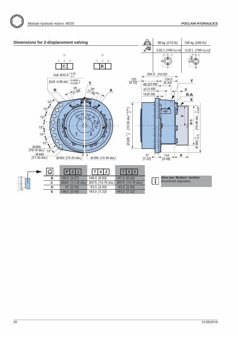
98 kg [215 lb] 136 kg [299 lb]
2,82 L [169 cu.in] 3,32 L [199 cu.in]
Dimensions for 2-displacement valving
1 2
D
3
C1 2
D
3
B
B 108,5 [4,27] 148,0 [5,83] 157,5 [6,20]C Ø280 [11,02 dia.] Ø375 [14,76 dia.] Ø375 [14,76 dia.]D 57 [2,24] 63,5 [2,50] 63,5 [2,50]E 138,5 [5,45] 183,5 [7,22] 183,5 [7,22]
Also see ’Brakes’ section(thumbnail opposite).
P 12 T 24 T 05

31/08/2016 21
Valv
ing
syst
ems
and
hydr
obas
esO
ptio
nsB
rake
Shaf
t mot
orW
heel
mot
or
Mod
ular
ity a
ndM
odel
cod
e
POCLAIN HYDRAULICS Modular hydraulic motorsMS35
82 kg [180 lb] 92 kg [202 lb]
1,95 L [117 cu.in] 2,12 L [127 cu.in]
Dimensions for 1-displacement (MS18) valving
1 2
D
3
1 21 2
D
3
1 1
91 kg [200 lb] 111 kg [245 lb]
1,95 L [117 cu.in] 2,12 L [127 cu.in]
Dimensions for 2-displacement (MS18) valving
1 2
D
3
21 2
D
3
1
B 76,7 [3,02] 98,5 [3,88] 92,5 [3,64] 114,3 [4,50]Ø C 247 [9,72] 250 [9,84] 273,6 [10,77] 273,6 [10,77]D 25 [0,98] 45,00 [1,77] 24,5 [0,96] 45,0 [1,77]E 155 [6,10] 121,50 [4,78] 128,5 [5,06] 128,5 [5,06]
T12 T19F12 F19
Also see “Brakes” section(thumbnail opposite).
22 31/08/2016
Modular hydraulic motors MS35 POCLAIN HYDRAULICS
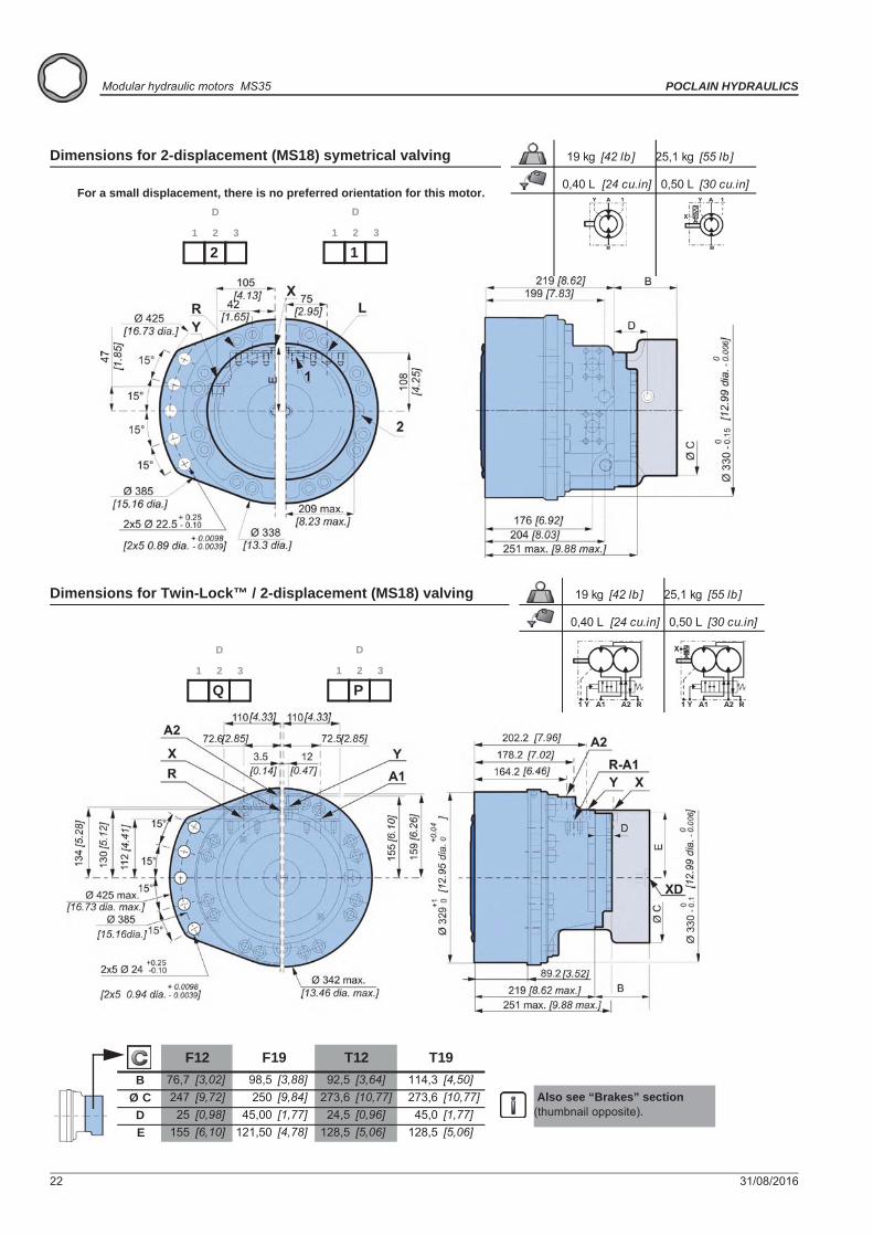
19 kg [42 lb] 25,1 kg [55 lb]
0,40 L [24 cu.in] 0,50 L [30 cu.in]
Dimensions for 2-displacement (MS18) symetrical valving
1 2
D
3
21 2
D
3
1
For a small displacement, there is no preferred orientation for this motor.
19 kg [42 lb] 25,1 kg [55 lb]
0,40 L [24 cu.in] 0,50 L [30 cu.in]
Dimensions for Twin-Lock™ / 2-displacement (MS18) valving
1 2
D
3
Q1 2
D
3
P
B 76,7 [3,02] 98,5 [3,88] 92,5 [3,64] 114,3 [4,50]Ø C 247 [9,72] 250 [9,84] 273,6 [10,77] 273,6 [10,77]D 25 [0,98] 45,00 [1,77] 24,5 [0,96] 45,0 [1,77]E 155 [6,10] 121,50 [4,78] 128,5 [5,06] 128,5 [5,06]
T12 T19F12 F19
Also see “Brakes” section(thumbnail opposite).
31/08/2016 23
Valv
ing
syst
ems
and
hydr
obas
esO
ptio
nsB
rake
Shaf
t mot
orW
heel
mot
or
Mod
ular
ity a
ndM
odel
cod
e
POCLAIN HYDRAULICS Modular hydraulic motorsMS35
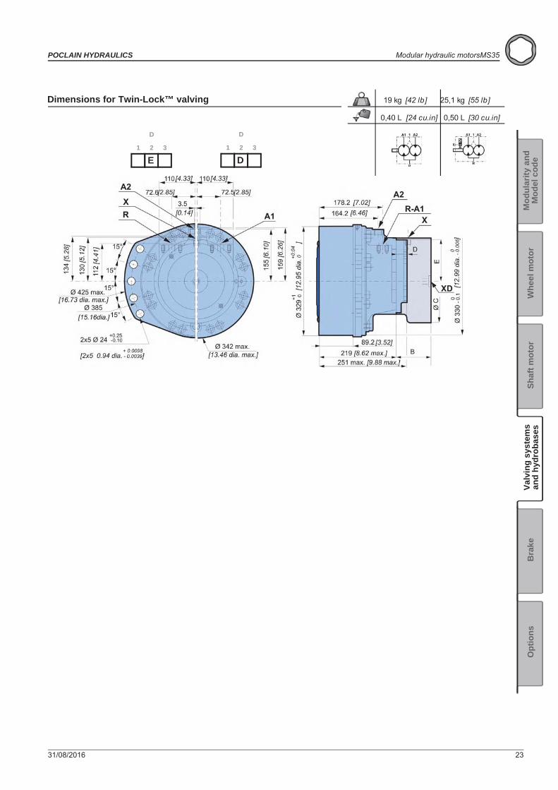
19 kg [42 lb] 25,1 kg [55 lb]
0,40 L [24 cu.in] 0,50 L [30 cu.in]
Dimensions for Twin-Lock™ valving
1 2
D
3
E1 2
D
3
D
24 31/08/2016
Modular hydraulic motors MS35 POCLAIN HYDRAULICS
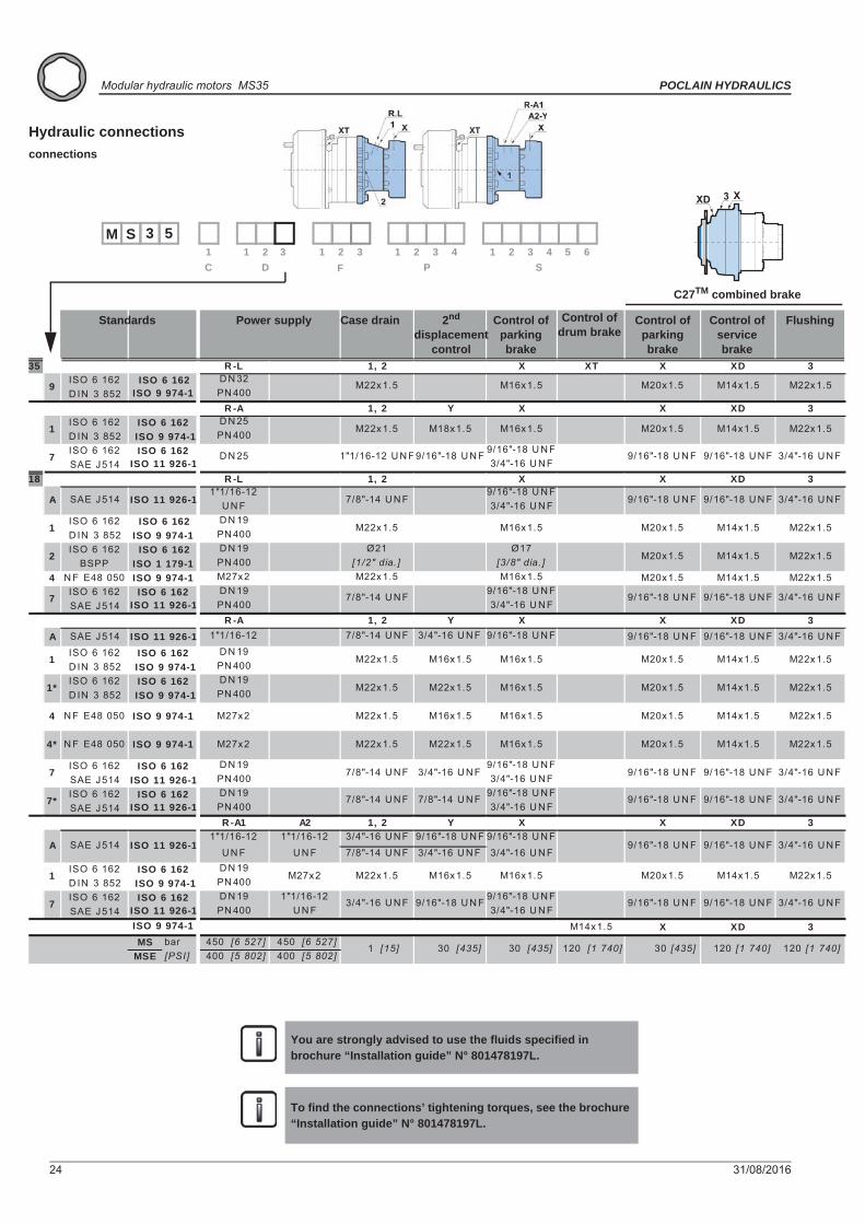
Hydraulic connectionsconnections
You are strongly advised to use the fluids specified in brochure “Installation guide” N° 801478197L.
To find the connections’ tightening torques, see the brochure “Installation guide” N° 801478197L.
Max.pressures
3 5S1 1 2
M1 2 3 4 5 6
S1 2 3 4
PDC F1 2 33
* : Only symmetrical valving
C27TM combined brake
X3XD
1C2C
1 di
spla
cem
ent
2 D
ispl
acem
ent
Twin
-Loc
kTM
35 X XD 3ISO 6 162D IN 3 852
X XD 3ISO 6 162D IN 3 852ISO 6 162SAE J514
18 X XD 3
ISO 6 162D IN 3 852ISO 6 162
BSPP4 N F E48 050 M20x1.5 M14x1.5 M22x1.5
ISO 6 162SAE J514
X XD 3A SAE J514 9/16"-18 U N F 9/16"-18 U N F 3/4"-16 U N F
ISO 6 162D IN 3 852ISO 6 162D IN 3 852
ISO 6 162SAE J514ISO 6 162SAE J514
X XD 3
ISO 6 162D IN 3 852ISO 6 162SAE J514
X XD 3MS bar 450 [6 527] 450 [6 527]
MSE [PSI] 400 [5 802] 400 [5 802]
D N 19PN 400
1"1/16-12U N F
1"1/16-12
U N F
D N 19PN 400D N 19PN 400
PN 400
D N 19PN 400
D N 19
D N 32PN 400
D N 25PN 400
R -A
M16x1.5M22x1.5
9/16"-18 U N F3/4"-16 U N F
X
7/8"-14 U N F
M16x1.5M16x1.5
M22x1.5
9/16"-18 U N F
M16x1.5
9/16"-18 U N F3/4"-16 U N F
3/4"-16 U N F3/4"-16 U N F7 ISO 6 162 7/8"-14 U N FISO 11 926-1
4 N F E48 050 ISO 9 974-1 M27x2
1* ISO 6 162 M22x1.5 ISO 9 974-1 PN 400
D N 19
R -L 1, 2
30
D N 19
M22x1.5
7/8"-14 U N F
Y
M22x1.5
7/8"-14 U N F
ISO 9 974-1
R -A 1, 2
ISO 6 162
D N 19PN 400
30 [435]1 [15] [435]
M22x1.5 M16x1.5ISO 9 974-1
D N 19PN 400
7 ISO 6 162ISO 11 926-1
ISO 6 1621
ISO 1 179-1 [1/2" dia. ] [3/8" dia. ]
9/16"-18 U N F3/4"-16 U N F
Ø21 Ø17
ISO 9 974-1M22x1.5 M16x1.5M16x1.5
PN 4001
7/8"-14 U N F
2 ISO 6 162
A SAE J514 ISO 11 926-1
3/4"-16 U N F 9/16"-18 U N F
ISO 9 974-1
ISO 11 926-1 1"1/16-12 7/8"-14 U N FY
M16x1.5M27x2
ISO 11 926-11"1/16-12 U N F9/16"-18 U N F
Y X
M16x1.5
9/16"-18 U N F
X3/4"-16 U N F
4* N F E48 050 ISO 9 974-1 M27x2 M22x1.5
7 ISO 6 162 D N 25
1, 2
1 ISO 6 162 M22x1.5 ISO 9 974-1
ISO 11 926-1R -A1 A2 1, 2 X
3/4"-16 U N F 9/16"-18 U N F 9/16"-18 U N F
3/4"-16 U N F
9/16"-18 U N F9/16"-18 U N F
3/4"-16 U N F
1 ISO 6 162 M27x2 ISO 9 974-1
7 ISO 6 162
9 ISO 9 974-1
A SAE J514 ISO 11 926-1
7* ISO 6 162
ISO 11 926-1 3/4"-16 U N F
M18x1.5
M22x1.5 M16x1.5 M16x1.5
7/8"-14 U N F 3/4"-16 U N FU N F
M22x1.5 M16x1.5 ISO 6 162R -L 1, 2 X XT
M20x1.5
M20x1.5
M20x1.5
M20x1.5 M14x1.5
M20x1.5 M14x1.5
M20x1.5 M14x1.5
30 [435] 120 [1 740]
9/16"-18 U N F 9/16"-18 U N F
120 [1 740]
M14x1.5
M14x1.5
9/16"-18 U N F 9/16"-18 U N F
9/16"-18 U N F 9/16"-18 U N F
M14x1.5
M14x1.5
M20x1.5 M14x1.5
9/16"-18 U N F 9/16"-18 U N F
M20x1.5 M14x1.5
3/4"-16 U N F
M22x1.5
9/16"-18 U N F 9/16"-18 U N F
9/16"-18 U N F 9/16"-18 U N F
M22x1.5
M22x1.5
3/4"-16 U N F
3/4"-16 U N F
M22x1.5
M22x1.5
120 [1 740]
M22x1.5
M22x1.5
M22x1.5
3/4"-16 U N F
3/4"-16 U N F
3/4"-16 U N F
U N F
1"1/16-12
1"1/16-12
M22x1.5
3/4"-16 U N F
M20x1.5 M14x1.5
9/16"-18 U N F 9/16"-18 U N F
Standards Power supply Case drain 2nd displacement
control
Control of drum brake
Control of parking brake
Control of servicebrake
FlushingControl of parking brake
31/08/2016 25
Valv
ing
syst
ems
and
hydr
obas
esO
ptio
nsB
rake
Shaf
t mot
orW
heel
mot
or
Mod
ular
ity a
ndM
odel
cod
e
POCLAIN HYDRAULICS Modular hydraulic motorsMS35
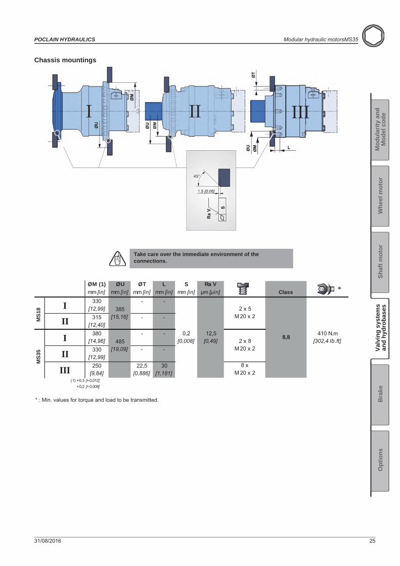
Chassis mountings
Take care over the immediate environment of theconnections.
ØM (1) ØU ØT L S Ra Vmm [in] mm [in] mm [in] mm [in] mm [in] μm [μin]
330 - -[12,99]
315 - -[12,40]
380 - -[14,96]
330 - -[12,99]
250 22,5 30[9,84] [0,886] [1,181]
(1) +0,3 [+0,012]+0,2 [+0,008]
II
III
385[15,16]
485[19,09]
[302,4 lb.ft]410 N.m
2 x 5 M 20 x 2
8 x M 20 x 2
2 x 8 M 20 x 2
8,80,2[0,008]
12,5[0,49]
III
I
Class
* : Min. values for torque and load to be transmitted.
MS1
8M
S35
*

26 31/08/2016
Modular hydraulic motors MS35 POCLAIN HYDRAULICS
Efficiency
Overall efficiency Actual output torqueAverage values given for guidance for code 0 displacement after 100 hours of operation with HV46 hydraulic fluid at 50°C [122°F].
The starting torque is taken to be approximately 85% of the first value for available pressure. For a precise calculation, consult your Poclain Hydraulics application engineer.
PSIbar
% RPM
N.mlb.ft
tr/minRPM
bar

31/08/2016 27
POCLAIN HYDRAULICS Modular hydraulic motors MS35
Valv
ing
syst
ems
and
hydr
obas
esO
ptio
nsB
rake
Shaf
t mot
orW
heel
mot
or
Mod
ular
ity a
ndM
odel
cod
e
BRAKESRear brake
Do not run-in the multidisc brakes.
A functional check of the parking brake must be carried out each time it is used as an auxiliary brake (or emergency brake). For all vehicles capable of speeds over 25 km/hour, please contact your Poclain Hydraulics application engineer.
M 3 5S1
C
1 2
D
3 1 2
P
3 4 1 2
S
3 4 5 6F 1 9
F 1 21 2
F
3
T 1 9
T 1 2
Brake principleThis is a multidisc brake which is activated by a lack of pressure. The spring exerts a force on the piston, which presses on the fixed and mobile discs, and immobilizes the shaft. The braking torque decreases in linear proportion to the brake release pressure.
Emergency brake release
F12 - F19
M16
140 N.m[103 lb.ft]
T12 - T19
11 840 Nm [8 730 lb.ft] 18 600 Nm [13 720 lb.ft]
7 695 Nm [5 680 lb.ft] 12 800 Nm [9 440 lb.ft]
8 880 Nm [6 550 lb.ft] 13 940 Nm [10 280 lb.ft]12 bar [174 PSI] 12 bar [174 PSI]30 bar [435 PSI] 30 bar [435 PSI]
170 cm³ [10,4 cu.in] 180 cm³ [11,0 cu.in]40 cm³ [2,4 cu.in] 70 cm³ [4,3 cu.in]
123 699 J 193 033 J
T 1 2 T 1 9
Parking brake torque at 0 bars on housing(new brakeDynamic emergency braking torque at 0 bars on housing (max. 10 uses of emergency brakesResidual parking braking at 0 bars on housing *Min. brake release pressureMax. brake release pressureOil capacityVolume for brake releaseMax. energy dissipation
* After emergency brake has been used
F 1 2 F 1 9
28 31/08/2016
Modular hydraulic motors MS35 POCLAIN HYDRAULICS
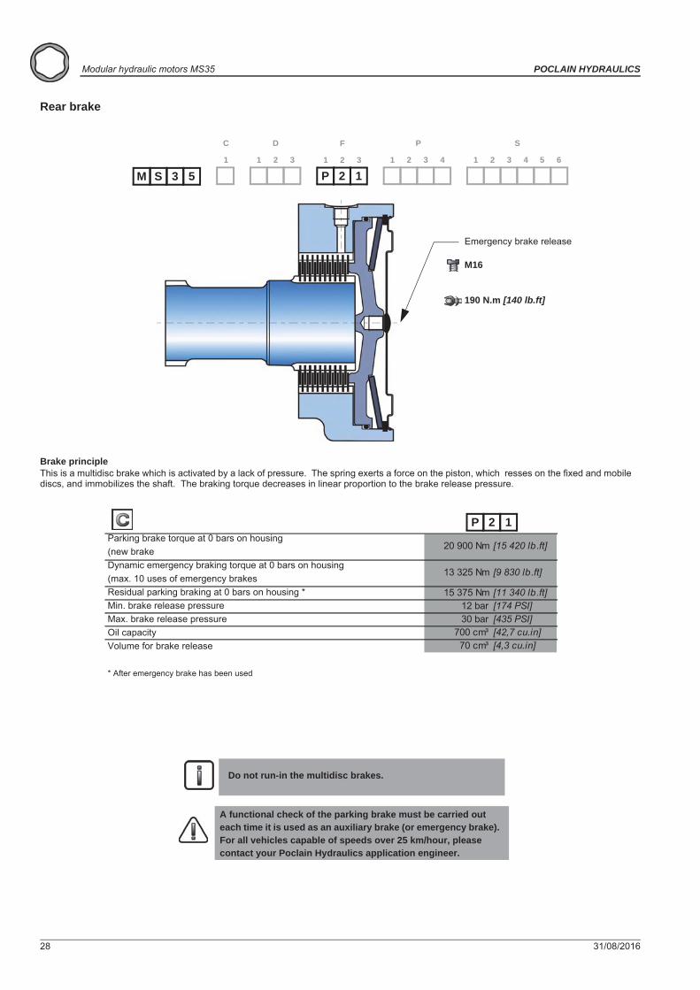
Rear brake
Do not run-in the multidisc brakes.
A functional check of the parking brake must be carried out each time it is used as an auxiliary brake (or emergency brake). For all vehicles capable of speeds over 25 km/hour, please contact your Poclain Hydraulics application engineer.
1
C
1 2
D
3 1 2
P
3 4 1 2
S
3 4 5 6
P 2 11 2
F
3
M 3 5S
Brake principleThis is a multidisc brake which is activated by a lack of pressure. The spring exerts a force on the piston, which resses on the fixed and mobile discs, and immobilizes the shaft. The braking torque decreases in linear proportion to the brake release pressure.
Emergency brake release
M16
190 N.m [140 lb.ft]
20 900 Nm [15 420 lb.ft]
13 325 Nm [9 830 lb.ft]
15 375 Nm [11 340 lb.ft]12 bar [174 PSI]30 bar [435 PSI]
700 cm³ [42,7 cu.in]70 cm³ [4,3 cu.in]
Parking brake torque at 0 bars on housing(new brakeDynamic emergency braking torque at 0 bars on housing (max. 10 uses of emergency brakesResidual parking braking at 0 bars on housing *Min. brake release pressureMax. brake release pressureOil capacityVolume for brake release
* After emergency brake has been used
P 2 1
31/08/2016 29
POCLAIN HYDRAULICS Modular hydraulic motors MS35
Valv
ing
syst
ems
and
hydr
obas
esO
ptio
nsB
rake
Shaf
t mot
orW
heel
mot
or
Mod
ular
ity a
ndM
odel
cod
e
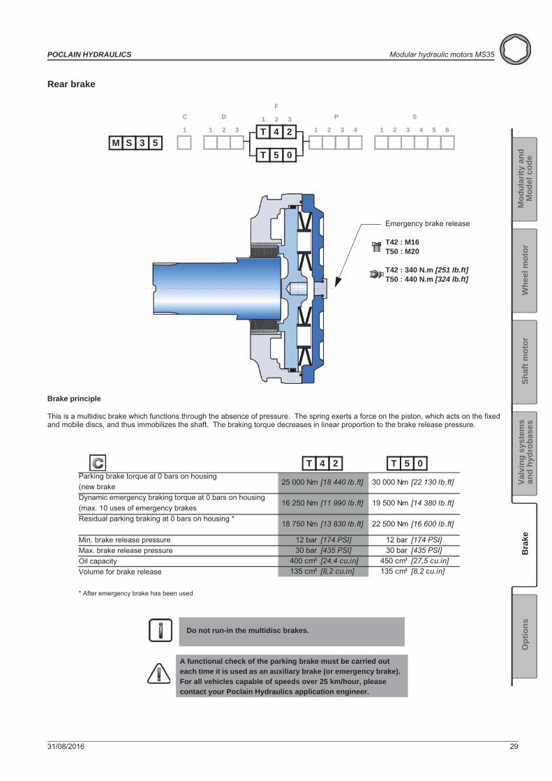
Rear brake
Do not run-in the multidisc brakes.
A functional check of the parking brake must be carried out each time it is used as an auxiliary brake (or emergency brake). For all vehicles capable of speeds over 25 km/hour, please contact your Poclain Hydraulics application engineer.
M 3 5T 5 0
S1
C
1 2
D
3 1 2
P
3 4 1 2
S
3 4 5 6T 4 21 2
F
3
Brake principle
This is a multidisc brake which functions through the absence of pressure. The spring exerts a force on the piston, which acts on the fixed and mobile discs, and thus immobilizes the shaft. The braking torque decreases in linear proportion to the brake release pressure.
Emergency brake release
T42 : M16T50 : M20
T42 : 340 N.m [251 lb.ft]T50 : 440 N.m [324 lb.ft]
25 000 Nm [18 440 lb.ft] 30 000 Nm [22 130 lb.ft]
16 250 Nm [11 990 lb.ft] 19 500 Nm [14 380 lb.ft]
18 750 Nm [13 830 lb.ft] 22 500 Nm [16 600 lb.ft]
12 bar [174 PSI] 12 bar [174 PSI]30 bar [435 PSI] 30 bar [435 PSI]
400 cm³ [24,4 cu.in] 450 cm³ [27,5 cu.in]135 cm³ [8,2 cu.in] 135 cm³ [8,2 cu.in]
Parking brake torque at 0 bars on housing(new brakeDynamic emergency braking torque at 0 bars on housing (max. 10 uses of emergency brakesResidual parking braking at 0 bars on housing *
Min. brake release pressureMax. brake release pressureOil capacityVolume for brake release
* After emergency brake has been used
T 4 2 T 5 0
30 31/08/2016
Modular hydraulic motors MS35 POCLAIN HYDRAULICS
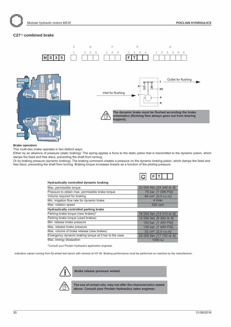
C27TM combined brake
Brake operationThis multi-disc brake operates in two distinct ways:Either by an absence of pressure (static braking): The spring applies a force to the static piston that is transmitted to the dynamic piston, whichdamps the fixed and free discs, preventing the shaft from turning. Or by braking pressure (dynamic braking): The braking command creates a pressure on the dynamic braking piston, which damps the fixed and free discs, preventing the shaft from turning. Braking torque increases linearly as a function of the piloting pressure.
Brake release pressure vented.
The use of certain oils, may not offer the characteristics stated above. Consult your Poclain Hydraulics sales engineer.
M 3 5S1
C
1 2
D
3 1 2
F
3 1 2
P
3 4 1 2
S
3 4 5 6
F T
33 000 Nm [24 340 lb .ft]75 bar [1 088 PSI]49 cm³ [3,0 cu.in]
19 000 Nm [14 010 lb .ft]13 000 Nm [9 590 lb .ft]
100 bar [1 450 PSI]135 bar [1 958 PSI]32 cm³ [2,0 cu.in]
24 000 Nm [17 700 lb .ft]
200 rpm
1000 kJ
4 l/min
F THydraulically controlled dynamic brakingMax. permissible torquePressure to obtain max. permissible brake torqueVolume required for brakingMin. irrigation flow rate for dynamic brakeMax. rotation speedHydraulically controlled parking brakeParking brake torque (new brakes)*Parking brake torque (used brakes)Min. release brake pressureMax. release brake pressureMax. volume of brake release (new brakes)Emergency dynamic braking torque at 0 bar to the caseMax. energy dissipation
*Consult your Poclain Hydraulics application engineer.
Indicative values coming from fly-wheel test bench with mineral oil HV 46. Braking performance must be performed on machine by the manufacturer.
X
1
R
A
XD
3
The dynamic brake must be flushed according the brake schematics (flushing flow always goes out from bearing support).
Inlet for flushing
Outlet for flushing
31/08/2016 31
POCLAIN HYDRAULICS Modular hydraulic motors MS35
Valv
ing
syst
ems
and
hydr
obas
esO
ptio
nsB
rake
Shaf
t mot
orW
heel
mot
or
Mod
ular
ity a
ndM
odel
cod
e
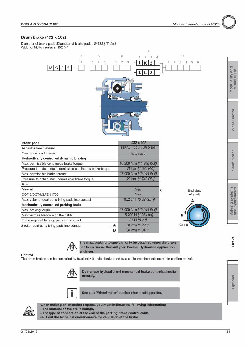
Drum brake (432 x 102)Diameter of brake pads :Diameter of brake pads : Ø 432 [17 dia.]Width of friction surface :102 [4]
ControlThe drum brakes can be controlled hydraulically (service brake) and by a cable (mechanical control for parking brake).
The max. braking torque can only be obtained when the brake has been run in. Consult your Poclain Hydraulics application engineer.
Do not use hydraulic and mechanical brake controls simulta-neously.
See also 'Wheel motor' section (thumbnail opposite).
When making an encoding request, you must indicate the following information:- The material of the brake linings,- The type of connection at the end of the parking brake control cable,- Fill out the technical questionnaire for validation of the brake.
M 3 51 K 2
S1
C
1 2
D
3 1 2
F
31 2
P
3 41 2
S
3 4 5 6
1 L 2
16 200 N.m [11 948 lb.ft]71 bar [1 030 PSI]
27 000 N.m [19 914 lb.ft]120 bar [1 740 PSI]
10,2 cm³ [0,62 cu.in]
27 000 N.m [19 914 lb.ft]5 700 N [1 281 lbf]
37 N [8 lbf]A 31 mm [1,22 '']B 34 mm [1,34 '']
432 x 102
KL
Brake padsAsbestos free materialCompensation for wearHydraulically controlled dynamic brakingMax. permissible continuous brake torquePressure to obtain max. permissible continuous brake torqueMax. permissible brake torquePressure to obtain max. permissible brake torqueFluidMineralDOT 3/DOT4/SAE J1703Max. volume required to bring pads into contactMechanically controlled parking brakeMax. braking torqueMax permissible force on the cableForce required to bring pads into contactStroke required to bring pads into contact
End viewof shaft
Cable
BERAL 1109 or JURID 505
Automatic
YesYes

32 31/08/2016
Modular hydraulic motors MS35 POCLAIN HYDRAULICS
31/08/2016 33
POCLAIN HYDRAULICS Modular hydraulic motors MS35
Valv
ing
syst
ems
and
hydr
obas
esO
ptio
nsB
rake
Shaf
t mot
orW
heel
mot
or
Mod
ular
ity a
ndM
odel
cod
e
OPTIONS
1 - Fluorinated elastomer sealsNitrile seals marked in the figure below replaced by fluorinated elastomer seals.
You can accumulate more than one optional part. Consult your Poclain Hydraulics sales engineer.
Consult your Poclain Hydraulics sales engineer.
M 3 5S1
C
1 2
D
3 1 2
F
3 1 2
P
3 4 1 2
S
3 4 5 6
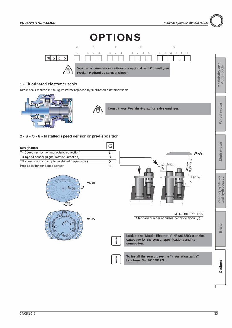
2 - S - Q - 8 - Installed speed sensor or predisposition
Look at the "Mobile Electronic" N° A01889D technical catalogue for the sensor specifications and its connection.
To install the sensor, see the ''Installation guide'' brochure No. 801478197L.
DesignationT4 Speed sensor (without rotation direction) 2TR Speed sensor (digital rotation direction) STD speed sensor (two phase shifted frequencies) QPredisposition for speed sensor 8
A-A
Max. length Y=Standard number of pulses per revolution=
MS18
MS3517.360

34 31/08/2016
Modular hydraulic motors MS35 POCLAIN HYDRAULICS
3 - Brake environmental cover without plugNo plug or hole in the cover.(see figure opposite)
5 - DrainageAdditional drain in the cover.
6 - Industrial supportReduction of around 50% from the rated value in the bearings' preload value.
7 - Diamond™Special treatment of the motor core which considerably increases its strength, making the motor much more tolerant to temporary instances of the operating conditions being exceeded.
A - Hollow shaft
For a precise calculation, consult your Poclain Hydraulics application engineer.
MS18 MS35 1 C
A Bmm [in] mm [in]
[2,36 dia.] [26,30]Ø 60 668
Radial load x 0.75No torque transmittable to the rear
F11 F12 F19 P35Available
31/08/2016 35
POCLAIN HYDRAULICS Modular hydraulic motors MS35
Valv
ing
syst
ems
and
hydr
obas
esO
ptio
nsB
rake
Shaf
t mot
orW
heel
mot
or
Mod
ular
ity a
ndM
odel
cod
e
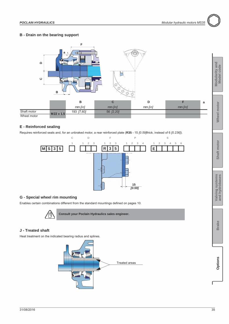
B - Drain on the bearing support
E - Reinforced sealingRequires reinforced seals and, for an unbraked motor, a rear reinforced plate (R35 - 15 [0.59]thick, instead of 6 [0.236]).
G - Special wheel rim mountingEnables certain combinations different from the standard mountings defined on pages 10.
J - Treated shaftHeat treatment on the indicated bearing radius and splines.
Consult your Poclain Hydraulics sales engineer.
a
193 [7,60] 56 [2,20]M22 x 1.5
FB C Dmm [in]mm [in]mm [in]mm [in]
DC
F
B
a
Shaft motorWheel motor
M 3 5 R 3 5 ES1
C
1 2
D
3 1 2
F
3 1 2
P
3 4 1 2
S
3 4 5 6
15[0.59]
Treated areas

31/08/2016
www.poclain-hydraulics.com
801 478 123F
801 478 193G
801 578 106H
801 578 118V
801 578 130J
A07447U
Not available
A14245J
31/08/2016
Poclain Hydraulics reserves the right to make any modifications it deems necessary to the products described in this document without prior notification.The information contained in this document must be confirmed by Poclain Hydraulics before any order is submitted.Illustrations are not binding.The Poclain Hydraulics brand is the property of Poclain Hydraulics S.A.


![MS HYDROBASES - Poclain Hydraulics · MS hydrobases POCLAIN HYDRAULICS ... [1,317] Z [1,575] 3,33 [0,131] Dimension on 2 pins ... Standards Power supply Case drain Control of parking](https://static.documents.pub/doc/80x56/5aeaf1547f8b9ab24d8e1120/ms-hydrobases-poclain-hydrobases-poclain-hydraulics-1317-z-1575-333.jpg)


