journa l homepage: www.e lsev ier .com/ locate /apcatb
eview
atalysts for methanol steam reforming—A review
andra Sáa, Hugo Silvaa, Lúcia Brandãoa, José M. Sousaa,b, Adélio Mendesa,∗
LEPAE-Departamento de Engenharia Química, Faculdade de Engenharia da Universidade do Porto, Rua Dr. Roberto Frias, 4200-465 Porto, PortugalDepartamento de Química, Universidade de Trás-os-Montes e Alto Douro, Apartado 202, 5001-911 Vila-Real Codex, Portugal
r t i c l e i n f o
rticle history:eceived 31 March 2010
a b s t r a c t
A large number of studies can be found in the literature regarding the production of new catalysts formethanol steam reforming. This work summarizes the latest developments on catalysts for this applica-
eceived in revised form 2 June 2010ccepted 7 June 2010vailable online 11 June 2010
eywords:atalysts
tion and is divided in two main groups: copper-based and group 8–10 metal-based catalysts. In eachsection, the strategies proposed by several authors to enhance the performance of the catalysts aredescribed. An overall comparison between the two groups shows that copper-based catalysts are themost active ones, while the 8–10 group catalysts present better results in terms of thermal stabilityand long-term stability. Very promising results were reported for both groups, enhancing the value of
P.T. pretreatment temperature, ◦CSBET BET Surface area, m2 g−1
SCH4 CH4 selectivity, %SCO CO selectivity, %SCO2 CO2 selectivity, %SCu Cu metal surface area, m2 g−1
Smetal metal surface area, m2 g−1
T temperature, ◦CTpre-activation pre-activation temperature, ◦CT reduction temperature, ◦C
1
bctMaaoicshsmtchstpaahbhrs(
C
C
C
rfrhRcbttcbhb
reductionXMeOH methanol conversion, %yi molar fraction of component i
. Introduction
In a time where environment problems are one of the worldiggest concerns, it is imperative to search and develop new andlean sources of energy. A promising environmentally friendlyechnology is the production of electrical power with fuel cells.
ore specifically, polymer electrolyte membrane fuel cells (PEMFC)re a suitable power generation device for small scale and transportpplications [1–4]. Although they are very attractive by their lowr none gas emissions, fuel cells require hydrogen as a fuel, whichs extremely difficult to store and to transport. Metallic hydridesan be used for hydrogen transportation but an attractive value oftorage capacity has not been achieved yet [5]. Reforming of alco-ols and hydrocarbons allows a hydrogen production in situ, whicholves the previously mentioned problems [6–12]. Even thoughethane is currently the main fuel in industrial hydrogen produc-
ion, other hydrogen carriers can be used for this reaction. Whenompared to other fuels, methanol presents several advantages forydrogen production. With only one carbon atom, methanol is theimplest of all alcohols. The absence of a strong C–C bond facilitateshe reforming at low temperatures (200–300 ◦C). This range of tem-eratures is very low when compared to other common fuels suchs methane, which is reformed above 500 ◦C [13], and ethanol, withreforming temperature around 400 ◦C [11]. Although methanol isighly toxic and miscible in water, it has the advantage of beingiodegradable, liquid at atmospheric conditions and has a highydrogen to carbon ratio [5,14–16]. In addition to the overall steameforming reaction, Eq. (1), two side reactions are commonly con-idered: methanol decomposition, Eq. (2), and water–gas shift, Eq.3), [17,18]:
H3OH + H2O � CO2 + 3H2 �H = 49.7 kJ mol−1 (1)
H3OH � CO + 2H2 �H = 90.2 kJ mol−1 (2)
O + H2O � CO2 + H2 �H = −41.2 kJ mol−1 (3)
Even though the purpose of the methanol steam reformingeaction is the production of hydrogen, there are other productsormed that must be taken into consideration. Besides the non-eacted water and methanol, the reaction mixture is composed byydrogen, carbon dioxide and small amounts of carbon monoxide.eminding that the hydrogen produced is for PEM fuel cell appli-ations, it is clear that the formation of carbon monoxide muste minimized. More specifically, its higher limit must be lowerhan 10 ppm, otherwise it poisons the anodic catalyst of the low
emperature fuel cells [19]. This highlights the importance of theatalyst performance in the reaction. Ideally, the catalyst shoulde highly active in order to achieve large amounts of hydrogen,ighly selective so that the carbon monoxide produced is negligi-le and finally it should present long-term stability. Copper-based
ironmental 99 (2010) 43–57
catalysts are the most commonly used for the methanol steamreforming reaction (MSR) due to their high activity and selectivity[20–26]. However, these catalysts are known for their pyrophoriccharacteristics and deactivation by thermal sintering [27,28], whichmotivates the search for other types of catalysts. In comparison toCu-based, group 8–10 catalysts have been reported in the litera-ture [29–31] as highly stable and with similar selectivity. However,concerning the catalytic activity, the later catalysts have the disad-vantage of producing less hydrogen than the copper-based ones.
This work summarizes the latest developments on catalysts forthe MSR reaction. Two major groups are considered, copper-basedand group 8–10 metals. In each section the strategies proposed byseveral authors to enhance the performance of the catalysts aredescribed. Catalysts for other reactions such as partial oxidationand autothermal steam reforming are not included in this study.
2. Copper-based catalysts
The most common catalysts for MSR are the copper-based ones.In order to improve their catalytic activity, several approaches arereported in the literature. Some studies are based on the additionof promoters [32–37], while others focus on the effect of the prepa-ration method [27,38–41]. The later effect has been investigated byseveral authors, who found that each step can affect the proper-ties of the catalyst. In other words, similar catalysts prepared bydifferent methods can present distinct catalytic properties.
2.1. Status of copper catalysts: metal dispersion, surface area andparticle size
The performance of copper-based catalysts is affected by thestatus of copper. More specifically, high values of copper disper-sion and metal surface area, along with small particle sizes, arethe targets to attain for the production of highly active catalysts.A summary of the physicochemical properties of various catalystsfound in the literature is presented in Table 1. In its turn, theinfluence of the preparation method and promoter on the perfor-mance of the steam reforming reaction catalysts in presented inTables 2 and 3. To facilitate the comparison between different cata-lysts, some authors use the commercially available CuO/ZnO/Al2O3catalyst as a reference [42–44].
An extensive variety of preparation methods can be foundin the literature for the copper-based catalysts, namely theconventional co-precipitation [32,45–49] and wet impregnation[44,50,51] methods. To enhance the catalytic activity and selectivityof the synthesized catalysts, some authors propose new prepara-tion methods or a variation of the conventional ones. It is worthnoticing that, in this study, selectivity is always towards the for-mation of CO unless said otherwise:
SCO = FCO
FCO + FCO2
100 (4)
where FCO and FCO2 are CO and CO2 flow rates, respectively, and SCOis the selectivity towards the formation of CO.
The increase of copper dispersion was one of the objectives ofYao et al. [27], Shishido et al. [39,52], Liu et al. [53] and Águila etal. [41] who compared and proposed different catalyst preparationmethods. Yao et al. [27] found that the oxalate gel co-precipitationmethod was the most effective in producing CuZrO2 catalysts withhigher copper dispersions and small crystallite size of the copperparticles. Comparing to the results of the impregnation method, the
copper area is approximately 18 times higher (Table 1), resultingin an increase of activity value of 30 times (Table 2). On the otherhand, the homogeneous precipitation using urea hydrolysis wasthe preparation method with better results in the work of Shishidoet al. [39,52]. As presented in Table 1, this method allowed the for-
S. Sá et al. / Applied Catalysis B: Environmental 99 (2010) 43–57 45
Table 1Physicochemical properties of copper catalysts found in the literature.
ation of Cu/ZnO and Cu/ZnO/Al2O3 catalysts with large metallicopper surface areas and highly dispersed Cu metal species. Liu etl. [53] pointed the soft reactive grinding technique as most effi-ient in producing highly active Cu-Mn spinel oxide catalysts. Inddition to high surface area and component dispersion, a catalyt-cally active Cu Mn O spinel phase was formed, improving the
1.5 1.5 4erformance of the copper-based catalyst. The activity increaseda. 55% when compared to the copper catalysts synthesized inhat work and CO selectivity decreased 50% (Table 2). The influ-nce of catalyst dispersion in increasing the catalyst activity can be
able 2nfluence of the preparation method on the performance of different Cu-based catalysts f
P: co-precipitation; CI: co-impregnation; CI-NP: co-impregnation with nanoparticle pmpregnation with 1,3-butanediol; OGCP: oxalate gel co-precipitation; PTSG: polymer teechnique; SRG-N: soft reactive grinding of oxalic acid with Cu/Zn nitrate precursors; SRGmpregnation.
64 – –
ermal synthesis; IMP: impregnation; OGCP: oxalate gel co-precipitation; SRG: soft
observed on Table 1; with the new Cu1.5Mn1.5O4 spinel phase, dis-persion increased one order of magnitude in comparison with someof the other copper catalysts synthesized [53]. A reflux methodfor the production of Cu-ZrO2 catalysts was used by Águila et al.[41], who reported that the insertion of copper during the reflux-ing treatment allows the formation of a highly dispersed copper
phase in the support. Jakdetchai et al. [40] improved the impreg-nation technique in order to achieve higher copper dispersion inCuZn catalysts. They prepared a copper zinc-impregnated FSM-16 (Folded Sheet Silica) catalyst by using a modified impregnation
ethod with 1,3-butanediol (Table 2). When compared to the cat-lyst prepared by the conventional wet impregnation method, thisew catalyst presented a higher copper dispersion that enhancedethanol conversion (ca. 62% higher) and decreased selectivity (no
O detected at 230 ◦C).The effects of the preparation method in the catalyst surface
rea were studied by Shen and Song [38]. They presented a com-arative study describing several techniques for the preparationf precursors for Cu/Zn/Al catalysts, namely, impregnation, co-recipitation and hydrothermal synthesis (Table 1). The catalystrepared by co-precipitation was the one which presented higherurface area (ca. 46% higher than wet impregnation) and methanolonversion. In order to achieve higher active surface area in theatalyst, as well as to prevent sintering and loss of copper parti-les with long operations periods, Purnama et al. [54] synthesizedCuO/ZrO2 using a polymer template technique. As described by
he authors, the morphology and porosity of zirconia are controlledy the confined space of the template. As a result, a nanostructuredaterial is formed with the desired high surface area. When com-
ared to commercial CuO/ZnO/Al2O3 catalysts, this study reportsigher catalytic activity, enhanced long-term stability and lowerO production. As presented in Table 2, the commercial catalystroduced an amount of CO 50 times higher than the synthesizeduO/ZrO2, for the same methanol conversion value. High cata-
yst surface area was also achieved in the work of Valdés-Solís
t al. [55] where nanoparticulate ternary oxides and mixtures ofxides were prepared by a template technique. Perovskite cata-ysts were found to be are inactive for this reaction, while CuMn2O4nd CuO/CeO2 showed good performances. The later catalysts pre-
– 0.0011a –– 0.003a –
sented surface areas more than 2 times higher than the one of aCuO/ZnO/ZrO2 prepared by co-precipitation (Table 2). These cat-alysts presented very reaction rate values during the first hour,having a maximum of 8.12 × 10⁻⁵ mol g−1 s−1 for the CuMn2O4catalyst. However, they suffered a strong deactivation after 20 h,which decreased the reaction rate to 2.41 × 10⁻⁵ mol g−1 s−1. Thesame group presented later a novel template technique based onthe coagulation–precipitation processes [56]. Again, high surfaceareas were achieved (250–300 m2 g−1) for a CuMn2O4 nanocat-alyst prepared by the silica-aquagel confined co-precipitationmethod. The stability was improved comparing to their previouswork [55]: the reaction rate decreased from an initial value of8.7 × 10−5 mol g−1 s−1 to 4.2 × 10⁻⁵ mol g−1 s−1 after 20 h. Anotherpreparation method worth mentioning is the urea-nitrate combus-tion method [25,57–59], that has been reported in the literatureas a simple preparation route, were catalysts are formed in a sin-gle step in ready-to-use form. Papavasiliou et al. [25] showed thatthe CuO-CeO2 catalyst surface area and crystallites size could becontrolled optimizing the preparation method. It was reported anoptimum fuel-to-oxidant ratio (urea/nitrates) of 4.17 and an opti-mum atomic Cu/(Cu + Ce) ratio of 0.15. Compared to a urea/nitratesratio of 1.2, the surface area increased ca. 4.3 times, methanol con-version increased from 52% to 100% and the activity increased ca.1.8 times. The same method was used in the preparation of Cu-Mn spinel oxide catalysts [57] which presented better results than
the CuO-CeO2 catalyst (Table 3). In a recent work, Papavasiliouet al. [58] used these optimized parameters for the synthesis ofnanocrystalline Cu-Ce-O and Cu-Mn-O catalyst layers supportedon metal foam. In comparison to the powder catalysts prepared by
B: Environmental 99 (2010) 43–57 47
tc
wwa
etpLadspasZsiZappo(btdrCsopmihca
2
casi
iciScamtlast
tCgot
Fig. 1. Schematic model of the microstructural characteristics of Cu/ZnO cata-
S. Sá et al. / Applied Catalysis
he same method, the foam catalysts presented similar structuralharacteristics and similar performances.
The influence of the preparation method in the catalytic activityas also studied by other authors as presented in Table 2. Catalystsith the same compositions were prepared by different methods
nd presented different performances [44,60,61].Promoters have been used to influence the status of copper and
nhance the performance of the catalyst. Studies on the promo-ional effects of zirconia [32,46] have revealed that this structuralromoter decreases the CO selectivity (Table 3). For instances,indström and Pettersson [62] studied the effect of zirconia inlumina-supported monolithic Cu-Zn catalysts. Although the Zroped catalysts were less active than the ones without Zr, theelectivity towards CO2 was higher. Jeong et al. [32] compared theerformance of Cu/ZnO/Al2O3 to the one of Cu/ZnO/ZrO2/Al2O3,nd reported an increase of approximately 16% in methanol conver-ion and a CO molar fraction 7.3 times lower, due to the presence ofrO2. Additionally, zirconia can promote copper dispersion as pre-ented in Table 1. Agrell et al. [46] reported an increase of ca. 37.5%n copper dispersion after adding ZrO2 to Cu/ZnO catalyst. Finally,rO2, as well as ZnO, can prevent copper particles from aggregationnd help stabilize the crystal size of copper [33]. Another structuralromoter is Al2O3, which provides a larger surface on which cop-er can be dispersed [32,46]. Agrell et al. [46] observed an increasef both total surface area (48.6–91.9 m2 g−1) and copper dispersion9.6–11.3%) due to Al2O3 (Table 1). A similar effect can be attainedy adding Cr2O3 [35,63], which acts as stabilizer of the copper struc-ure reducing sintering. The promotional effects of CeO2 have beenescribed in the literature [51,55,59,64], in particular, Liu et al. [65]eported high activity of the Cu/CeO2 catalysts compared to Cu/ZnO,u/Zn(Al)O and Cu/Al2O3 with the same Cu loading and under theame reaction conditions. It was suggested that the high activityf the Cu/CeO2 catalysts was due to the highly dispersed Cu metalarticles and the strong metal-support interaction between the Cuetal and CeO2 support. The catalytic activity has been reported to
mprove with the addition of yttria [36] which appears to stabilize aigh copper surface area [37]. Finally, Houteit et al. [66] reports thatesium oxide can prevent copper oxide crystallites from sinteringnd its reduction into metallic Cu.
.2. Microstructural characteristics
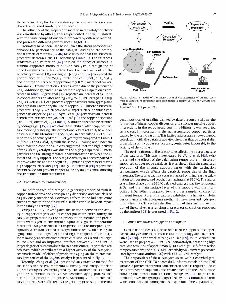
The performance of a catalyst is generally associated with itsopper surface area and consequently dispersion and particle size,s previously mentioned. However, defects in the bulk structure,uch as microstrain and structural disorder, can also have an impactn the catalytic activity [67].
Kniep et al. [67] investigated the relation between the activ-ty of copper catalysts and its copper phase structure. During theatalysts preparation by the co-precipitation method, the precip-tates were aged in the mother liquor at a given temperature.tructural changes occurred in this period, and the amorphous pre-ipitates were transformed into crystalline ones. By increasing theging time, the catalysts exhibited higher copper surface area, aore homogeneous microstructure with smaller Cu and ZnO crys-
alline sizes and an improved interface between Cu and ZnO. Aarger degree of microstrain in the nanostructured Cu particles waschieved, which contributed to a higher activity of the catalyst. Achematic model of effect of precipitate aging on the microstruc-ural properties of the Cu/ZnO catalyst is presented in Fig. 1.
Recently, Wang et al. [61] presented an attractive method for
he fabrication of environmentally friendly and energy-efficientu/ZnO catalysts. As highlighted by the authors, the extendedrinding is similar to the above described aging process thatccurs in co-precipitation process. Accordingly, the microstruc-ural properties are affected by the grinding process. The thermal
lysts obtained from differently aged precipitates (amorphous (<30 min), crystalline(>30 min)).Reprinted from Kniep et al. [67].
decomposition of grinding derived oxalate precursors allows theformation of higher copper dispersion and stronger metal–supportinteractions in the oxide precursors. In addition, it was reportedan increased microstrain in the nanostructured copper particlescaused by the grinding time. This lattice microstrain showed a goodcorrelation with the catalyst activity, showing that structural dis-order along with copper surface area, contributes favourably to theactivity of the catalyst.
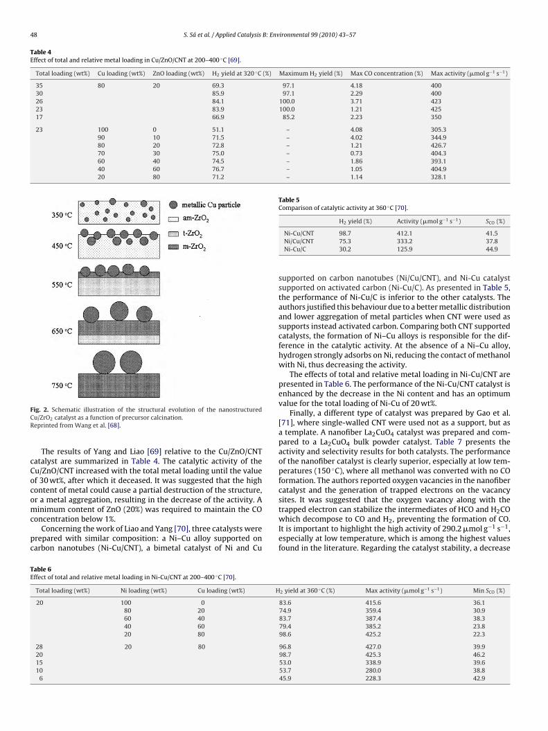
The posttreatment of the precipitates affects the microstructureof the catalysts. This was investigated by Wang et al. [68], whopresented the effects of the calcination temperature in zirconia-supported copper oxide catalysts. It was shown that the structuralevolution of the zirconia support varies with the calcinationtemperature, which affects the catalytic properties of the finalmaterials. The catalyst activity was enhanced with increasing calci-nation temperature, and reached a maximum at 550 ◦C. The majorcrystalline phase of the 550 ◦C calcined catalyst was the tetragonalZrO2, and the main surface layer of the support was the mon-oclinic ZrO2. When compared to the other samples calcined atdifferent temperatures, this catalyst exhibited the higher catalyticperformance in what concerns methanol conversion and hydrogenproduction rate. The schematic illustration of the structural evolu-tion of the catalyst as a function of precursor calcination proposedby the authors [68] is presented in Fig. 2.
2.3. Carbon nanotubes as supports or templates
Carbon nanotubes (CNT) have been used as supports for copper-based catalysts due to their structural morphology and character-istics [69,70]. In the work of Yang and Liao [69], multi-walled CNTwere used to prepare a Cu/ZnO-CNT nanocatalyst, presenting highcatalytic activities of approximately 400 �mol g−1 s−1, for reactiontemperatures around 400 ◦C. Similar activity values were presentedlater by the same authors [70] with a Ni-Cu/CNT catalyst.
The preparation of these catalysts starts with a chemical pre-treatment of the CNT. To successfully adsorb metals on the CNTsurface, a pretreatment with concentrated acids is required. These
acids remove the impurities and create defects on the CNT surface,allowing the introduction functional groups [69,70]. The pretreat-ment improves the hydrophilicity of CNT by the addition of ethanol,which enhances the homogeneous dispersion of metal particles.
48 S. Sá et al. / Applied Catalysis B: Environmental 99 (2010) 43–57
Table 4Effect of total and relative metal loading in Cu/ZnO/CNT at 200–400 ◦C [69].
Total loading (wt%) Cu loading (wt%) ZnO loading (wt%) H2 yield at 320 ◦C (%) Maximum H2 yield (%) Max CO concentration (%) Max activity (�mol g−1 s−1)
Table 5Comparison of catalytic activity at 360 ◦C [70].
H2 yield (%) Activity (�mol g−1 s−1) SCO (%)
TE
ig. 2. Schematic illustration of the structural evolution of the nanostructuredu/ZrO2 catalyst as a function of precursor calcination.eprinted from Wang et al. [68].
The results of Yang and Liao [69] relative to the Cu/ZnO/CNTatalyst are summarized in Table 4. The catalytic activity of theu/ZnO/CNT increased with the total metal loading until the valuef 30 wt%, after which it deceased. It was suggested that the highontent of metal could cause a partial destruction of the structure,r a metal aggregation, resulting in the decrease of the activity. Ainimum content of ZnO (20%) was required to maintain the CO
oncentration below 1%.Concerning the work of Liao and Yang [70], three catalysts were
repared with similar composition: a Ni–Cu alloy supported onarbon nanotubes (Ni-Cu/CNT), a bimetal catalyst of Ni and Cu
able 6ffect of total and relative metal loading in Ni-Cu/CNT at 200–400 ◦C [70].
Total loading (wt%) Ni loading (wt%) Cu loading (wt%) H
supported on carbon nanotubes (Ni/Cu/CNT), and Ni-Cu catalystsupported on activated carbon (Ni-Cu/C). As presented in Table 5,the performance of Ni-Cu/C is inferior to the other catalysts. Theauthors justified this behaviour due to a better metallic distributionand lower aggregation of metal particles when CNT were used assupports instead activated carbon. Comparing both CNT supportedcatalysts, the formation of Ni–Cu alloys is responsible for the dif-ference in the catalytic activity. At the absence of a Ni–Cu alloy,hydrogen strongly adsorbs on Ni, reducing the contact of methanolwith Ni, thus decreasing the activity.
The effects of total and relative metal loading in Ni-Cu/CNT arepresented in Table 6. The performance of the Ni-Cu/CNT catalyst isenhanced by the decrease in the Ni content and has an optimumvalue for the total loading of Ni-Cu of 20 wt%.
Finally, a different type of catalyst was prepared by Gao et al.[71], where single-walled CNT were used not as a support, but asa template. A nanofiber La2CuO4 catalyst was prepared and com-pared to a La2CuO4 bulk powder catalyst. Table 7 presents theactivity and selectivity results for both catalysts. The performanceof the nanofiber catalyst is clearly superior, especially at low tem-peratures (150 ◦C), where all methanol was converted with no COformation. The authors reported oxygen vacancies in the nanofibercatalyst and the generation of trapped electrons on the vacancysites. It was suggested that the oxygen vacancy along with thetrapped electron can stabilize the intermediates of HCO and H CO
2which decompose to CO and H2, preventing the formation of CO.It is important to highlight the high activity of 290.2 �mol g−1 s−1,especially at low temperature, which is among the highest valuesfound in the literature. Regarding the catalyst stability, a decrease
2 yield at 360 ◦C (%) Max activity (�mol g−1 s−1) Min SCO (%)
f approximately 2% in methanol conversion was reported dur-ng the 60 h lifetime test, but a long-term stability test was notresented.
.4. Reduction temperature
Prior to the reaction, a catalyst reduction is required to converturface copper oxide into metallic copper-active phase for hydro-en production. With the purpose of determining the temperaturet which each catalyst is reduced, a characterization technique cane used – temperature programmed reduction (TPR). In the litera-ure, a duality of opinions is reported concerning the interpretationf the TPR analysis results. Some authors report that the lowerhe temperature needed for the reduction, the easier the reduc-ion is, which may result from a high dispersion and large surfacerea of the catalyst. Several authors have corroborated this trendith their work, namely Shen and Song [38] and Breen and Ross
23] whose results are presented in Table 8. It cannot be estab-ished a linear correlation between the activity and the reductionemperature, but the trend indicates that easier reducibility fol-ows higher activity. In contrast, other authors concluded that theeducibility of the copper species does not indicate any informa-ion about the catalyst activity, and in some cases the catalystshat were more difficult to reduce tend to be more active [72,73].s an example, in Jones and Hagelin-Weaver study [44] the cata-
yst with best performance was the one with the highest reductionemperature.
.5. Catalyst deactivation
Copper catalysts are described in the literature as easily deac-ivated [74]. Deactivation is generally attributed to a change inxidation state, catalyst sintering or coke deposition. Poisoning ofhe catalyst can also occur if there are foreign species in the feed
ixture as chloride and sulphur [55]. In the work of Valdés-Solís etl. [55], deactivation was related to the specific feed composition
nd space velocity. It was reported coke formation and active phaseintering. Deactivation by the presence of coke was also reportedy Cao et al. [75] when water was absent in the feed. In a studyf deactivation of supported copper catalysts for methanol syn-hesis, Kurtz et al. [74] found that high concentrations of CO led
able 8nfluence of the reduction temperature in the catalytic activity.
to an enhanced sintering of the metallic Cu particles. It was alsoreported that Al2O3 is a structural promoter for Cu/ZnO catalysts,which inhibits thermal sintering of Cu crystallites. Matsumura andIshibe [76] reported that the growth of ZnO and ZrO2 particle wasaccompanied by catalyst deactivation. The Zn/Cu ratio was ana-lyzed by Jones et al. [77] and correlated to catalyst deactivation.After a reductive treatment and exposure to reaction conditions, theratio between Zn/Cu increased, less active Cu phase was exposed,which lead to deactivation.
Copper-alumina catalysts can be stabilized by cerium as sug-gested in the work of Patel and Pant [51]. They performed studiescomparing cerium promoted Cu-Zn-Ce-Al-oxide catalysts withcatalysts containing only zinc promoter. The long run-time per-formance of the ceria containing catalysts was superior due to itshigh oxygen storage capacity. Under MSR reductive conditions,partially reduced ceria sites are formed producing mobile oxy-gen that facilitates the coke gasification, inhibiting coke deposition[51].
The addition of oxygen to the feed mixture (oxidative methanolsteam reforming) helps to reduce catalyst deactivation becauseoxygen reduces or even suppresses coke formation. As describedabove, the increase of steam to carbon ratio is also favourable todecrease the catalyst deactivation [55].
2.6. Reaction mechanism
The MSR reaction mechanism over Cu-based catalysts has beenvastly discussed in the literature. Several mechanisms have beenproposed, but there is small agreement about which one is themost accurate. The production of hydrogen was first thought to beaccomplished by the methanol decomposition followed by watergas shift reaction [78–81]:
CH3OH � CO + 2H2 (5)
CO + H2O � CO2 + H2 (6)
According to this mechanism, the carbon monoxide concen-trations in the products should be higher than the equilibriumconcentration. However, experimental studies have shown thatCu-based catalysts produce CO at concentrations lower thanequilibrium [79,80]. Abandoning this simple reaction sequence,
50 S. Sá et al. / Applied Catalysis B: Environmental 99 (2010) 43–57
F ions of Jiang et al., Peppley et al. and Takezawa and Iwasa, including different kinds ofrR
Tf
2
H
H
pkftfmt
C
mUsfias
ws
C
H
H
S
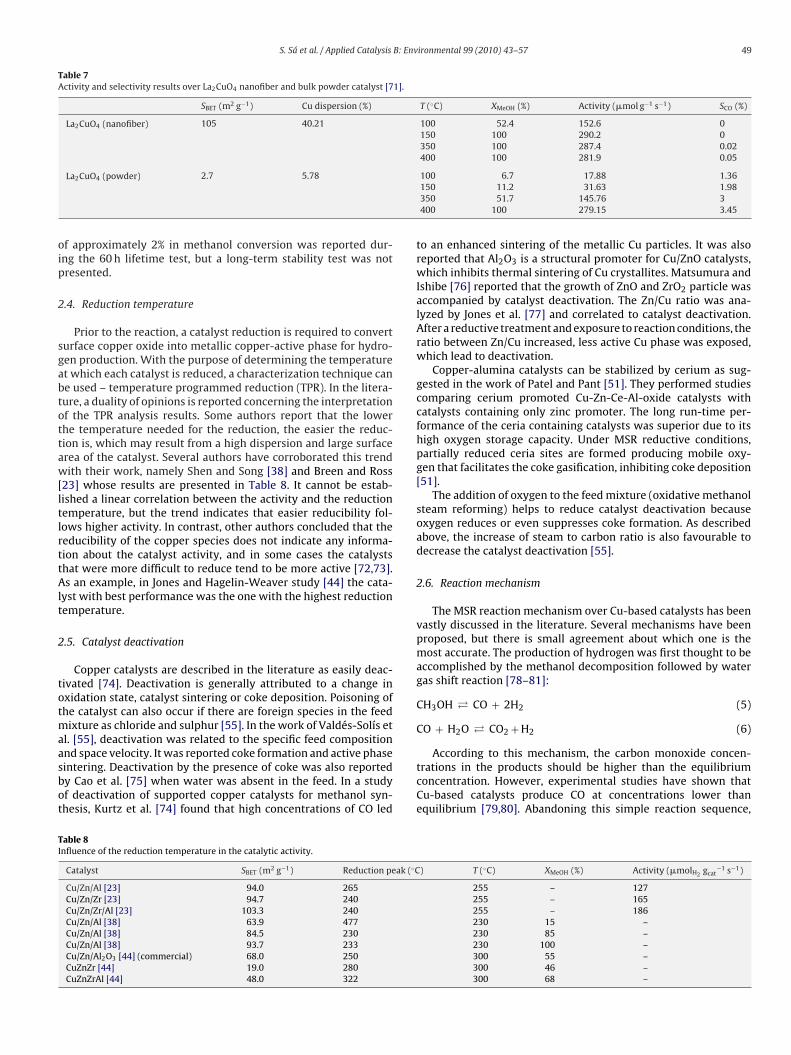
ig. 3. Catalysis cycle of methanol steam reforming on the basis of the investigateactive surface sites SA and SB.eprinted from Frank et al. [84].
akahashi et al. [21] suggested a mechanism involving a methylormate intermediate.
CH3OH → HCOOCH3 + 2H2 (7)
COOCH3 + H2O → CH3OH + HCOOH (8)
COOH → H2 + CO2 (9)
This mechanism was supported by Jiang et al. [22,82] who pro-osed a Langmuir–Hinshelwood rate expression based in a singleind of active sites. Methanol dehydrogenates to produce methylormate and hydrogen. Afterwards, methyl formate is hydrolyzedo form formic acid and methanol, followed by decomposition oformic acid to form carbon dioxide [32]. As CO is not formed by
ethanol decomposition, it is suggested that its formation is dueo the reverse water gas shift reaction:
O2 + H2 � CO + H2O (10)
The latter mechanism was the starting point for developing aore comprehensive kinetic model presented by Peppley et al. [18].nlike Jiang et al. [22,82] who described only one type of active
ites, Peppley et al. proposed two types of active sites: one activeor MSR and the water–gas shift reactions, and another to primar-ly support the decomposition reaction. Additionally, these authorsssumed that hydrogen adsorption does not compete for the activeites that the oxygen-containing species adsorb on.
Another mechanism was proposed by Takezawa and Iwasa [83],ho found formaldehyde and formic acid intermediates in the
team reforming reaction over Cu-based catalysts:
H3OH → HCHO + H2 (11)
CHO + H2O → HCOOH + H2 (12)
COOH → CO2 + H2 (13)
This mechanism was supported by Breen and Ross [23] andhishido et al. [52], who confirmed that CH3OH was dehydro-
Fig. 4. XRD spectra of Pd/ZnO with different reduction pretreatment temperatures.Reprinted from Iwasa et al. [88].
S. Sá et al. / Applied Catalysis B: Environmental 99 (2010) 43–57 51
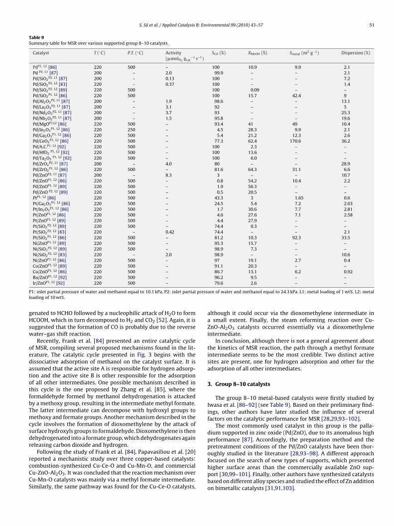
Table 9Summary table for MSR over various supported group 8–10 catalysts.
1: inlet partial pressure of water and methanol equal to 10.1 kPa. P2: inlet partialoading of 10 wt%.
enated to HCHO followed by a nucleophilic attack of H2O to formCOOH, which in turn decomposed to H2 and CO2 [52]. Again, it is
uggested that the formation of CO is probably due to the reverseater–gas shift reaction.
Recently, Frank et al. [84] presented an entire catalytic cyclef MSR, compiling several proposed mechanisms found in the lit-rature. The catalytic cycle presented in Fig. 3 begins with theissociative adsorption of methanol on the catalyst surface. It isssumed that the active site A is responsible for hydrogen adsorp-ion and the active site B is other responsible for the adsorptionf all other intermediates. One possible mechanism described inhis cycle is the one proposed by Zhang et al. [85], where theormaldehyde formed by methanol dehydrogenation is attackedy a methoxy group, resulting in the intermediate methyl formate.he latter intermediate can decompose with hydroxyl groups toethoxy and formate groups. Another mechanism described in the
ycle involves the formation of dioxomethylene by the attack ofurface hydroxyls groups to formaldehyde. Dioxomethylene is thenehydrogenated into a formate group, which dehydrogenates againeleasing carbon dioxide and hydrogen.
Following the study of Frank et al. [84], Papavasiliou et al. [20]
eported a mechanistic study over three copper-based catalysts:ombustion-synthesized Cu-Ce-O and Cu-Mn-O, and commercialu-ZnO-Al2O3. It was concluded that the reaction mechanism overu-Mn-O catalysts was mainly via a methyl formate intermediate.imilarly, the same pathway was found for the Cu-Ce-O catalysts,
79.6 2.6 – –
ure of water and methanol equal to 24.3 kPa. L1: metal loading of 1 wt%. L2: metal
although it could occur via the dioxomethylene intermediate ina small extent. Finally, the steam reforming reaction over Cu-ZnO-Al2O3 catalysts occurred essentially via a dioxomethyleneintermediate.
In conclusion, although there is not a general agreement aboutthe kinetics of MSR reaction, the path through a methyl formateintermediate seems to be the most credible. Two distinct activesites are present, one for hydrogen adsorption and other for theadsorption of all other intermediates.
3. Group 8–10 catalysts
The group 8–10 metal-based catalysts were firstly studied byIwasa et al. [86–92] (see Table 9). Based on their preliminary find-ings, other authors have later studied the influence of severalfactors on the catalytic performance for MSR [28,29,93–102].
The most commonly used catalyst in this group is the palla-dium supported in zinc oxide (Pd/ZnO), due to its anomalous highperformance [87]. Accordingly, the preparation method and thepretreatment conditions of the Pd/ZnO catalysts have been thor-oughly studied in the literature [28,93–98]. A different approach
focused on the search of new types of supports, which presentedhigher surface areas than the commercially available ZnO sup-port [30,99–101]. Finally, other authors have synthesized catalystsbased on different alloy species and studied the effect of Zn additionon bimetallic catalysts [31,91,103].
52 S. Sá et al. / Applied Catalysis B: Env
FPR
3
rfArCtP(gtoc
P[teisp
PNtobtoiAwmdboiaaf8f
2 −1
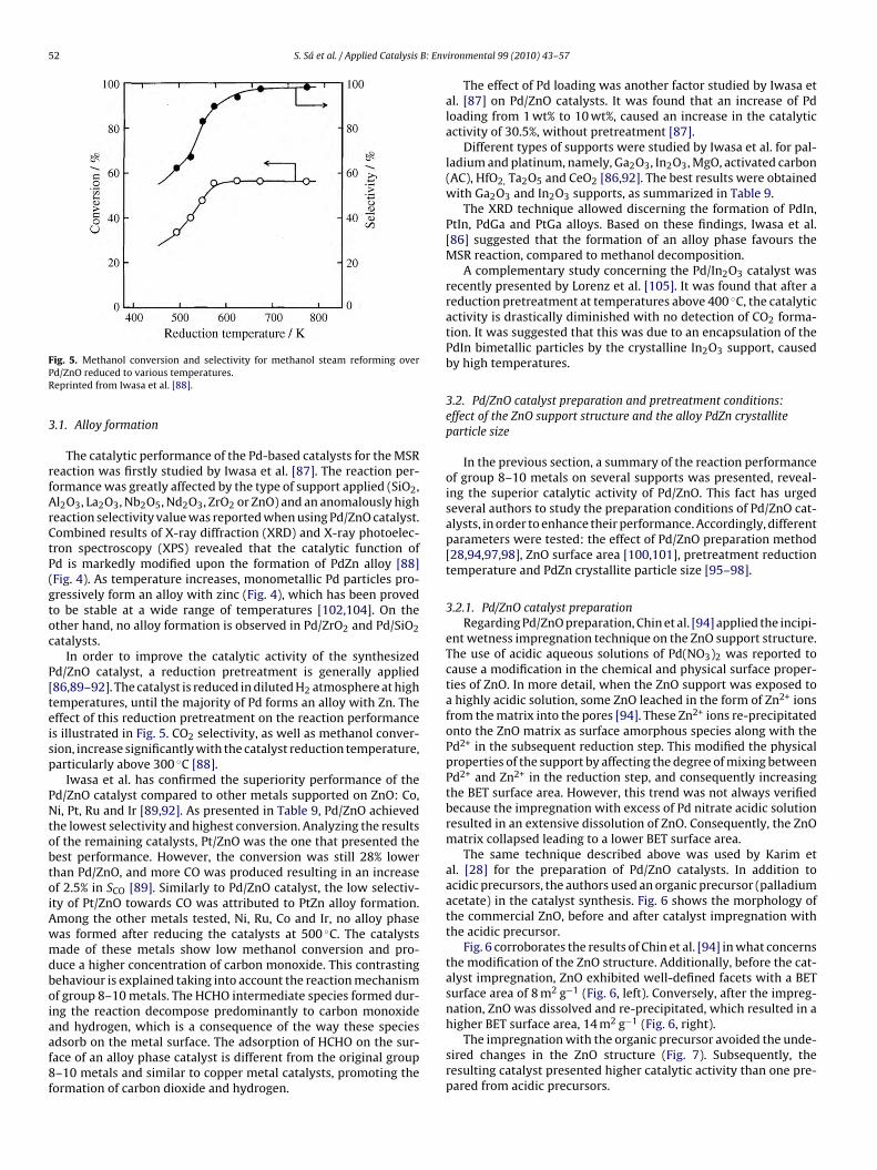
ig. 5. Methanol conversion and selectivity for methanol steam reforming overd/ZnO reduced to various temperatures.eprinted from Iwasa et al. [88].
.1. Alloy formation
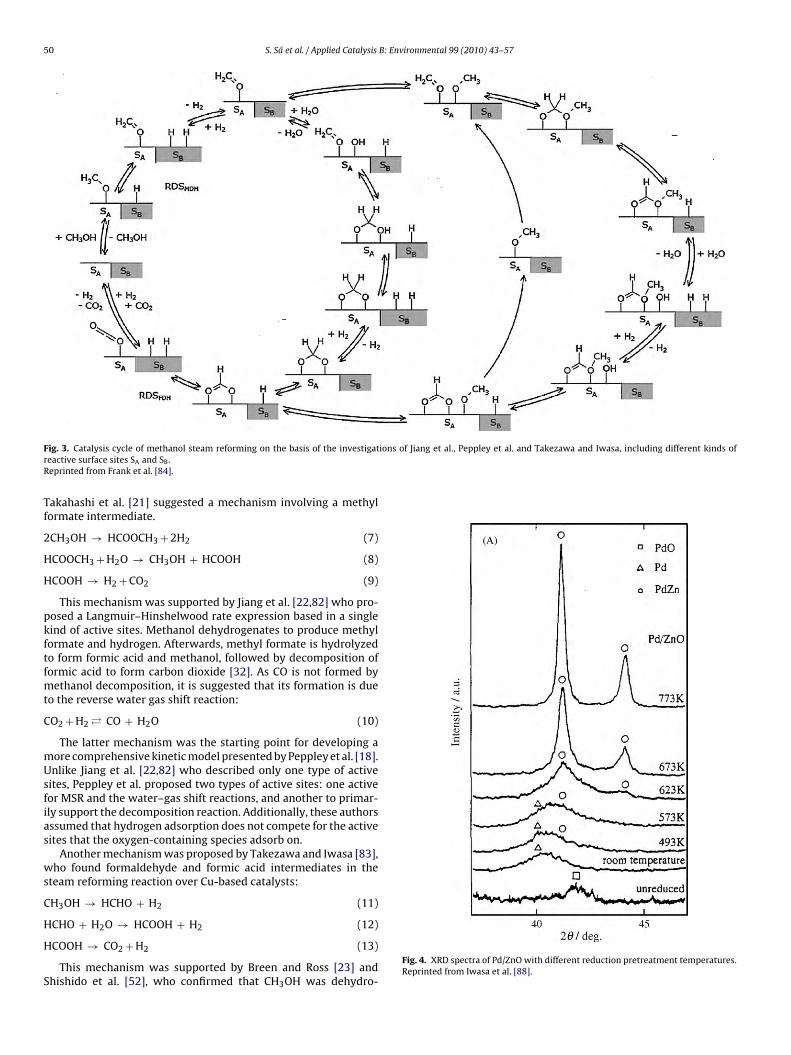
The catalytic performance of the Pd-based catalysts for the MSReaction was firstly studied by Iwasa et al. [87]. The reaction per-ormance was greatly affected by the type of support applied (SiO2,l2O3, La2O3, Nb2O5, Nd2O3, ZrO2 or ZnO) and an anomalously higheaction selectivity value was reported when using Pd/ZnO catalyst.ombined results of X-ray diffraction (XRD) and X-ray photoelec-ron spectroscopy (XPS) revealed that the catalytic function ofd is markedly modified upon the formation of PdZn alloy [88]Fig. 4). As temperature increases, monometallic Pd particles pro-ressively form an alloy with zinc (Fig. 4), which has been provedo be stable at a wide range of temperatures [102,104]. On thether hand, no alloy formation is observed in Pd/ZrO2 and Pd/SiO2atalysts.
In order to improve the catalytic activity of the synthesizedd/ZnO catalyst, a reduction pretreatment is generally applied86,89–92]. The catalyst is reduced in diluted H2 atmosphere at highemperatures, until the majority of Pd forms an alloy with Zn. Theffect of this reduction pretreatment on the reaction performances illustrated in Fig. 5. CO2 selectivity, as well as methanol conver-ion, increase significantly with the catalyst reduction temperature,articularly above 300 ◦C [88].
Iwasa et al. has confirmed the superiority performance of thed/ZnO catalyst compared to other metals supported on ZnO: Co,i, Pt, Ru and Ir [89,92]. As presented in Table 9, Pd/ZnO achieved
he lowest selectivity and highest conversion. Analyzing the resultsf the remaining catalysts, Pt/ZnO was the one that presented theest performance. However, the conversion was still 28% lowerhan Pd/ZnO, and more CO was produced resulting in an increasef 2.5% in SCO [89]. Similarly to Pd/ZnO catalyst, the low selectiv-ty of Pt/ZnO towards CO was attributed to PtZn alloy formation.mong the other metals tested, Ni, Ru, Co and Ir, no alloy phaseas formed after reducing the catalysts at 500 ◦C. The catalystsade of these metals show low methanol conversion and pro-
uce a higher concentration of carbon monoxide. This contrastingehaviour is explained taking into account the reaction mechanismf group 8–10 metals. The HCHO intermediate species formed dur-ng the reaction decompose predominantly to carbon monoxide
nd hydrogen, which is a consequence of the way these speciesdsorb on the metal surface. The adsorption of HCHO on the sur-ace of an alloy phase catalyst is different from the original group–10 metals and similar to copper metal catalysts, promoting theormation of carbon dioxide and hydrogen.
ironmental 99 (2010) 43–57
The effect of Pd loading was another factor studied by Iwasa etal. [87] on Pd/ZnO catalysts. It was found that an increase of Pdloading from 1 wt% to 10 wt%, caused an increase in the catalyticactivity of 30.5%, without pretreatment [87].
Different types of supports were studied by Iwasa et al. for pal-ladium and platinum, namely, Ga2O3, In2O3, MgO, activated carbon(AC), HfO2, Ta2O5 and CeO2 [86,92]. The best results were obtainedwith Ga2O3 and In2O3 supports, as summarized in Table 9.
The XRD technique allowed discerning the formation of PdIn,PtIn, PdGa and PtGa alloys. Based on these findings, Iwasa et al.[86] suggested that the formation of an alloy phase favours theMSR reaction, compared to methanol decomposition.
A complementary study concerning the Pd/In2O3 catalyst wasrecently presented by Lorenz et al. [105]. It was found that after areduction pretreatment at temperatures above 400 ◦C, the catalyticactivity is drastically diminished with no detection of CO2 forma-tion. It was suggested that this was due to an encapsulation of thePdIn bimetallic particles by the crystalline In2O3 support, causedby high temperatures.
3.2. Pd/ZnO catalyst preparation and pretreatment conditions:effect of the ZnO support structure and the alloy PdZn crystalliteparticle size
In the previous section, a summary of the reaction performanceof group 8–10 metals on several supports was presented, reveal-ing the superior catalytic activity of Pd/ZnO. This fact has urgedseveral authors to study the preparation conditions of Pd/ZnO cat-alysts, in order to enhance their performance. Accordingly, differentparameters were tested: the effect of Pd/ZnO preparation method[28,94,97,98], ZnO surface area [100,101], pretreatment reductiontemperature and PdZn crystallite particle size [95–98].
3.2.1. Pd/ZnO catalyst preparationRegarding Pd/ZnO preparation, Chin et al. [94] applied the incipi-
ent wetness impregnation technique on the ZnO support structure.The use of acidic aqueous solutions of Pd(NO3)2 was reported tocause a modification in the chemical and physical surface proper-ties of ZnO. In more detail, when the ZnO support was exposed toa highly acidic solution, some ZnO leached in the form of Zn2+ ionsfrom the matrix into the pores [94]. These Zn2+ ions re-precipitatedonto the ZnO matrix as surface amorphous species along with thePd2+ in the subsequent reduction step. This modified the physicalproperties of the support by affecting the degree of mixing betweenPd2+ and Zn2+ in the reduction step, and consequently increasingthe BET surface area. However, this trend was not always verifiedbecause the impregnation with excess of Pd nitrate acidic solutionresulted in an extensive dissolution of ZnO. Consequently, the ZnOmatrix collapsed leading to a lower BET surface area.
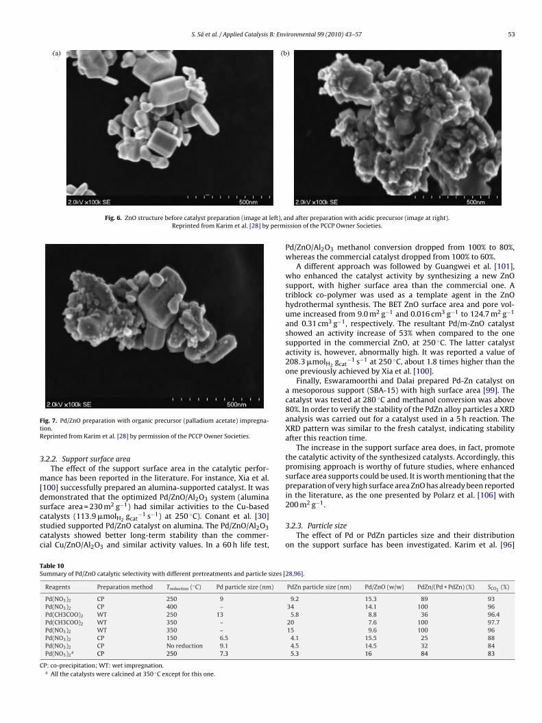
The same technique described above was used by Karim etal. [28] for the preparation of Pd/ZnO catalysts. In addition toacidic precursors, the authors used an organic precursor (palladiumacetate) in the catalyst synthesis. Fig. 6 shows the morphology ofthe commercial ZnO, before and after catalyst impregnation withthe acidic precursor.
Fig. 6 corroborates the results of Chin et al. [94] in what concernsthe modification of the ZnO structure. Additionally, before the cat-alyst impregnation, ZnO exhibited well-defined facets with a BETsurface area of 8 m2 g−1 (Fig. 6, left). Conversely, after the impreg-nation, ZnO was dissolved and re-precipitated, which resulted in a
higher BET surface area, 14 m g (Fig. 6, right).
The impregnation with the organic precursor avoided the unde-sired changes in the ZnO structure (Fig. 7). Subsequently, theresulting catalyst presented higher catalytic activity than one pre-pared from acidic precursors.
S. Sá et al. / Applied Catalysis B: Environmental 99 (2010) 43–57 53
Fig. 6. ZnO structure before catalyst preparation (image at left), aReprinted from Karim et al. [28] by perm
FtR
3
m[dscscc
TS
C
ig. 7. Pd/ZnO preparation with organic precursor (palladium acetate) impregna-ion.eprinted from Karim et al. [28] by permission of the PCCP Owner Societies.
.2.2. Support surface areaThe effect of the support surface area in the catalytic perfor-
ance has been reported in the literature. For instance, Xia et al.100] successfully prepared an alumina-supported catalyst. It wasemonstrated that the optimized Pd/ZnO/Al2O3 system (alumina
urface area = 230 m2 g−1) had similar activities to the Cu-basedatalysts (113.9 �molH2 gcat
−1 s−1) at 250 ◦C). Conant et al. [30]tudied supported Pd/ZnO catalyst on alumina. The Pd/ZnO/Al2O3atalysts showed better long-term stability than the commer-ial Cu/ZnO/Al2O3 and similar activity values. In a 60 h life test,
able 10ummary of Pd/ZnO catalytic selectivity with different pretreatments and particle sizes [
P: co-precipitation; WT: wet impregnation.a All the catalysts were calcined at 350 ◦C except for this one.
nd after preparation with acidic precursor (image at right).ission of the PCCP Owner Societies.
Pd/ZnO/Al2O3 methanol conversion dropped from 100% to 80%,whereas the commercial catalyst dropped from 100% to 60%.
A different approach was followed by Guangwei et al. [101],who enhanced the catalyst activity by synthesizing a new ZnOsupport, with higher surface area than the commercial one. Atriblock co-polymer was used as a template agent in the ZnOhydrothermal synthesis. The BET ZnO surface area and pore vol-ume increased from 9.0 m2 g−1 and 0.016 cm3 g−1 to 124.7 m2 g−1
and 0.31 cm3 g−1, respectively. The resultant Pd/m-ZnO catalystshowed an activity increase of 53% when compared to the onesupported in the commercial ZnO, at 250 ◦C. The latter catalystactivity is, however, abnormally high. It was reported a value of208.3 �molH2 gcat
−1 s−1 at 250 ◦C, about 1.8 times higher than theone previously achieved by Xia et al. [100].
Finally, Eswaramoorthi and Dalai prepared Pd-Zn catalyst ona mesoporous support (SBA-15) with high surface area [99]. Thecatalyst was tested at 280 ◦C and methanol conversion was above80%. In order to verify the stability of the PdZn alloy particles a XRDanalysis was carried out for a catalyst used in a 5 h reaction. TheXRD pattern was similar to the fresh catalyst, indicating stabilityafter this reaction time.
The increase in the support surface area does, in fact, promotethe catalytic activity of the synthesized catalysts. Accordingly, thispromising approach is worthy of future studies, where enhancedsurface area supports could be used. It is worth mentioning that thepreparation of very high surface area ZnO has already been reportedin the literature, as the one presented by Polarz et al. [106] with
2 −1
200 m g .
3.2.3. Particle sizeThe effect of Pd or PdZn particles size and their distribution
on the support surface has been investigated. Karim et al. [96]
54 S. Sá et al. / Applied Catalysis B: Environmental 99 (2010) 43–57
talystsm Iwa
vphfttotctAtt
trsws
pcgpt
p5KwopTcf
3
azFi
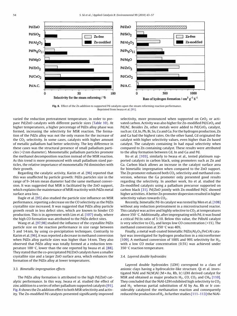
Fig. 8. Effect of the Zn addition to supported Pd caReprinted fro
aried the reduction pretreatment temperature, in order to pre-are Pd/ZnO catalysts with different particle sizes (Table 10). Atigher temperatures, a higher percentage of PdZn alloy phase was
ormed, increasing the selectivity for MSR reaction. The forma-ion of the PdZn alloy was not the only reason for the increase ofhe CO2 selectivity. In some cases, catalysts with higher amountf metallic palladium had better selectivity. The key difference inhese cases was the structural presence of small palladium parti-les (<2 nm diameter). Monometallic palladium particles promotehe methanol decomposition reaction instead of the MSR reaction.s this trend is more pronounced with small palladium sized par-
icles, the relative importance of monometallic Pd diminishes withheir growth.
Regarding the catalytic activity, Karim et al. [96] reported thathis was unaffected by particle growth: PdZn particles size in theange of 9–34 nm mean diameter had the same methanol conver-ion. It was suggested that MSR is facilitated by the ZnO support,hich explains the maintenance of MSR reactivity with PdZn metal
urface area loss.Dagle et al. [95] also studied the particle size influence on MSR
erformance, reporting a decrease on the CO selectivity as the PdZnrystallite size increased. It was suggested that PdZn alloy particlerowth result in less defect sites, which are known to hinder COroduction. This is in agreement with Lim et al. [107] study, wherehe high CO formation was attributed to the PdZn defect sites.
Wang et al. [97,98] studied the influence of the crystallite PdZnarticle size on the reaction performance in size range betweenand 14 nm, by using co-precipitation techniques. Contrarily to
arim et al. [96], it was reported a decrease in methanol conversionhen PdZn alloy particle sizes was higher than 14 nm. They also
bserved that PdZn alloy was totally formed at a reduction tem-erature 100 ◦C, lower than the one reported by Iwasa et al. [88].hey stated that the co-precipitated Pd/ZnO catalysts have a smallerrystallite size and a larger ZnO surface area, which enhances theormation of the PdZn alloy at lower temperatures.
.3. Bimetallic impregnation effects
The PdZn alloy formation is attributed to the high Pd/ZnO cat-lytic performance. In this way, Iwasa et al. studied the effect ofinc addition to a series of other palladium supported catalysts [91].ig. 8 shows the Zn addition effect to both MSR selectivity and activ-ty. The Zn-modified Pd catalysts presented significantly improved
upon the steam reforming reaction performance.sa et al. [91].
selectivity, more pronounced when supported on CeO2 or acti-vated carbon. Activity was also higher for Zn-modified Pd/CeO2 andPd/AC. Besides Zn, other metals were added to Pd/CeO2 catalyst,such as: Cd, In, Pb, Bi, Sn, Cu and Ga. For the hydrogen production, Znand Ga had the highest rates. On the other hand, Cd originated thecatalyst with higher selectivity values, even higher than Zn basedcatalyst. The catalysts containing In had equal selectivity whencompared to Zn containing catalyst. These results were attributedto the alloy formation between Cd, In and Ga and Pd.
Ito et al. [103], similarly to Iwasa et al., tested platinum sup-ported catalysts in carbon black, using promoters such as Zn andGa. Carbon black allows an increase in the catalyst surface areafor bimetallic impregnation when compared to the ZnO support.The Zn promoter enhanced both CO2 selectivity and methanol con-version, whereas the Ga promoter only presented good resultsregarding the selectivity. In another work, Ito et al. studied theZn-modified catalysts using a palladium precursor supported oncarbon black [31]. Pd/ZnO jointly with Zn-modified Pd/C showedhigher activities. A better Zn promoter dispersion resulted in higherselectivity values towards CO2.
Recently, bimetallic Pd-In catalyst was tested by Men et al. [108]without any reduction pretreatment in a microstructured reactor.This catalyst was active and highly selective to CO2 at temperaturesabove 350 ◦C. Additionally, after impregnating with Pd, it was founda critical Pd:In ratio of 5:10. Below this value, the PdInAl catalystis very selective to CO2 and keeps low CO concentration (<1%). Themethanol conversion at 350 ◦C was 40%.
Finally, a metal wall-coated bimetallic PdZn/Al2O3/FeCrAl cata-lyst was investigated for hydrogen production in a microreformer[109]. A methanol conversion of 100% and 99% selectivity for H2,with a low CO molar concentration (0.5%) was achieved under350 ◦C reaction temperature.
3.4. Layered double hydroxides
Layered double hydroxides (LDH) correspond to a class ofanionic clays having a hydrocalcite-like structure. Qi et al. inves-tigated NiAl and Ni(M)Al (M = Au, Rh, Ir) LDH derived catalyst for
MSR and obtained as major products H2, CO, CO2 and CH4 [110].They concluded that the NiAl-LDH exhibited high selectivity to CO2and H2, whereas partial substitution of Al by Au, Rh or Ir con-siderably catalyzed the methanation reaction and consequentlyreduced the production of H2. In further studies [111–113] the NiAl-
S. Sá et al. / Applied Catalysis B: Environmental 99 (2010) 43–57 55
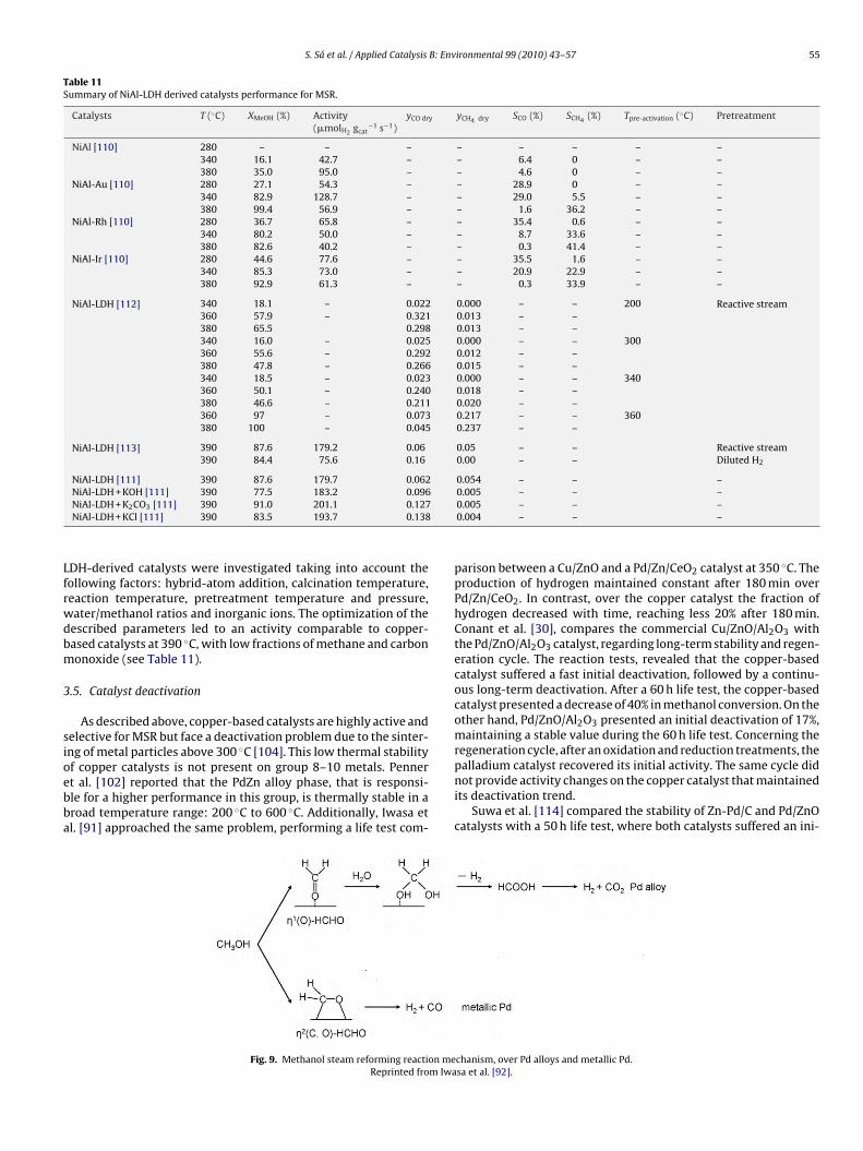
Table 11Summary of NiAl-LDH derived catalysts performance for MSR.
DH-derived catalysts were investigated taking into account theollowing factors: hybrid-atom addition, calcination temperature,eaction temperature, pretreatment temperature and pressure,ater/methanol ratios and inorganic ions. The optimization of theescribed parameters led to an activity comparable to copper-ased catalysts at 390 ◦C, with low fractions of methane and carbononoxide (see Table 11).
.5. Catalyst deactivation
As described above, copper-based catalysts are highly active andelective for MSR but face a deactivation problem due to the sinter-ng of metal particles above 300 ◦C [104]. This low thermal stability
f copper catalysts is not present on group 8–10 metals. Pennert al. [102] reported that the PdZn alloy phase, that is responsi-le for a higher performance in this group, is thermally stable in aroad temperature range: 200 ◦C to 600 ◦C. Additionally, Iwasa etl. [91] approached the same problem, performing a life test com-
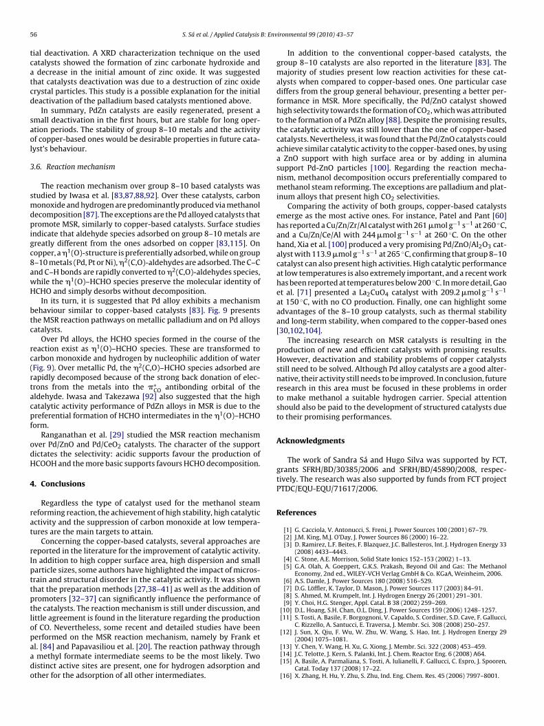
Fig. 9. Methanol steam reforming reaction meReprinted from Iwa
0.005 – – –0.005 – – –0.004 – – –
parison between a Cu/ZnO and a Pd/Zn/CeO2 catalyst at 350 ◦C. Theproduction of hydrogen maintained constant after 180 min overPd/Zn/CeO2. In contrast, over the copper catalyst the fraction ofhydrogen decreased with time, reaching less 20% after 180 min.Conant et al. [30], compares the commercial Cu/ZnO/Al2O3 withthe Pd/ZnO/Al2O3 catalyst, regarding long-term stability and regen-eration cycle. The reaction tests, revealed that the copper-basedcatalyst suffered a fast initial deactivation, followed by a continu-ous long-term deactivation. After a 60 h life test, the copper-basedcatalyst presented a decrease of 40% in methanol conversion. On theother hand, Pd/ZnO/Al2O3 presented an initial deactivation of 17%,maintaining a stable value during the 60 h life test. Concerning theregeneration cycle, after an oxidation and reduction treatments, the
palladium catalyst recovered its initial activity. The same cycle didnot provide activity changes on the copper catalyst that maintainedits deactivation trend.
Suwa et al. [114] compared the stability of Zn-Pd/C and Pd/ZnOcatalysts with a 50 h life test, where both catalysts suffered an ini-
chanism, over Pd alloys and metallic Pd.sa et al. [92].
5 B: Env
tcatcd
saol
3
smdpigc8awH
btc
rc(rtacpf
odH
4
rat
rIpttptlopaado
6 S. Sá et al. / Applied Catalysis
ial deactivation. A XRD characterization technique on the usedatalysts showed the formation of zinc carbonate hydroxide anddecrease in the initial amount of zinc oxide. It was suggested
hat catalysts deactivation was due to a destruction of zinc oxiderystal particles. This study is a possible explanation for the initialeactivation of the palladium based catalysts mentioned above.
In summary, PdZn catalysts are easily regenerated, present amall deactivation in the first hours, but are stable for long oper-tion periods. The stability of group 8–10 metals and the activityf copper-based ones would be desirable properties in future cata-yst’s behaviour.
.6. Reaction mechanism
The reaction mechanism over group 8–10 based catalysts wastudied by Iwasa et al. [83,87,88,92]. Over these catalysts, carbononoxide and hydrogen are predominantly produced via methanol
ecomposition [87]. The exceptions are the Pd alloyed catalysts thatromote MSR, similarly to copper-based catalysts. Surface studies
ndicate that aldehyde species adsorbed on group 8–10 metals arereatly different from the ones adsorbed on copper [83,115]. Onopper, a �1(O)-structure is preferentially adsorbed, while on group–10 metals (Pd, Pt or Ni), �2(C,O)-aldehydes are adsorbed. The C–Cnd C–H bonds are rapidly converted to �2(C,O)-aldehydes species,hile the �1(O)–HCHO species preserve the molecular identity ofCHO and simply desorbs without decomposition.
In its turn, it is suggested that Pd alloy exhibits a mechanismehaviour similar to copper-based catalysts [83]. Fig. 9 presentshe MSR reaction pathways on metallic palladium and on Pd alloysatalysts.
Over Pd alloys, the HCHO species formed in the course of theeaction exist as �1(O)–HCHO species. These are transformed toarbon monoxide and hydrogen by nucleophilic addition of waterFig. 9). Over metallic Pd, the �2(C,O)–HCHO species adsorbed areapidly decomposed because of the strong back donation of elec-rons from the metals into the �∗
CO antibonding orbital of theldehyde. Iwasa and Takezawa [92] also suggested that the highatalytic activity performance of PdZn alloys in MSR is due to thereferential formation of HCHO intermediates in the �1(O)–HCHOorm.
Ranganathan et al. [29] studied the MSR reaction mechanismver Pd/ZnO and Pd/CeO2 catalysts. The character of the supportictates the selectivity: acidic supports favour the production ofCOOH and the more basic supports favours HCHO decomposition.
. Conclusions
Regardless the type of catalyst used for the methanol steameforming reaction, the achievement of high stability, high catalyticctivity and the suppression of carbon monoxide at low tempera-ures are the main targets to attain.
Concerning the copper-based catalysts, several approaches areeported in the literature for the improvement of catalytic activity.n addition to high copper surface area, high dispersion and smallarticle sizes, some authors have highlighted the impact of micros-rain and structural disorder in the catalytic activity. It was shownhat the preparation methods [27,38–41] as well as the addition ofromoters [32–37] can significantly influence the performance ofhe catalysts. The reaction mechanism is still under discussion, andittle agreement is found in the literature regarding the productionf CO. Nevertheless, some recent and detailed studies have been
erformed on the MSR reaction mechanism, namely by Frank etl. [84] and Papavasiliou et al. [20]. The reaction pathway throughmethyl formate intermediate seems to be the most likely. Twoistinct active sites are present, one for hydrogen adsorption andther for the adsorption of all other intermediates.
ironmental 99 (2010) 43–57
In addition to the conventional copper-based catalysts, thegroup 8–10 catalysts are also reported in the literature [83]. Themajority of studies present low reaction activities for these cat-alysts when compared to copper-based ones. One particular casediffers from the group general behaviour, presenting a better per-formance in MSR. More specifically, the Pd/ZnO catalyst showedhigh selectivity towards the formation of CO2, which was attributedto the formation of a PdZn alloy [88]. Despite the promising results,the catalytic activity was still lower than the one of copper-basedcatalysts. Nevertheless, it was found that the Pd/ZnO catalysts couldachieve similar catalytic activity to the copper-based ones, by usinga ZnO support with high surface area or by adding in aluminasupport Pd-ZnO particles [100]. Regarding the reaction mecha-nism, methanol decomposition occurs preferentially compared tomethanol steam reforming. The exceptions are palladium and plat-inum alloys that present high CO2 selectivities.
Comparing the activity of both groups, copper-based catalystsemerge as the most active ones. For instance, Patel and Pant [60]has reported a Cu/Zn/Zr/Al catalyst with 261 �mol g−1 s−1 at 260 ◦C,and a Cu/Zn/Ce/Al with 244 �mol g−1 s−1 at 260 ◦C. On the otherhand, Xia et al. [100] produced a very promising Pd/ZnO/Al2O3 cat-alyst with 113.9 �mol g−1 s−1 at 265 ◦C, confirming that group 8–10catalyst can also present high activities. High catalytic performanceat low temperatures is also extremely important, and a recent workhas been reported at temperatures below 200 ◦C. In more detail, Gaoet al. [71] presented a La2CuO4 catalyst with 209.2 �mol g−1 s−1
at 150 ◦C, with no CO production. Finally, one can highlight someadvantages of the 8–10 group catalysts, such as thermal stabilityand long-term stability, when compared to the copper-based ones[30,102,104].
The increasing research on MSR catalysts is resulting in theproduction of new and efficient catalysts with promising results.However, deactivation and stability problems of copper catalystsstill need to be solved. Although Pd alloy catalysts are a good alter-native, their activity still needs to be improved. In conclusion, futureresearch in this area must be focused in these problems in orderto make methanol a suitable hydrogen carrier. Special attentionshould also be paid to the development of structured catalysts dueto their promising performances.
Acknowledgments
The work of Sandra Sá and Hugo Silva was supported by FCT,grants SFRH/BD/30385/2006 and SFRH/BD/45890/2008, respec-tively. The research was also supported by funds from FCT projectPTDC/EQU-EQU/71617/2006.
References
[1] G. Cacciola, V. Antonucci, S. Freni, J. Power Sources 100 (2001) 67–79.[2] J.M. King, M.J. O’Day, J. Power Sources 86 (2000) 16–22.[3] D. Ramirez, L.F. Beites, F. Blazquez, J.C. Ballesteros, Int. J. Hydrogen Energy 33
(2008) 4433–4443.[4] C. Stone, A.E. Morrison, Solid State Ionics 152–153 (2002) 1–13.[5] G.A. Olah, A. Goeppert, G.K.S. Prakash, Beyond Oil and Gas: The Methanol
Economy, 2nd ed., WILEY-VCH Verlag GmbH & Co. KGaA, Weinheim, 2006.[6] A.S. Damle, J. Power Sources 180 (2008) 516–529.[7] D.G. Löffler, K. Taylor, D. Mason, J. Power Sources 117 (2003) 84–91.[8] S. Ahmed, M. Krumpelt, Int. J. Hydrogen Energy 26 (2001) 291–301.[9] Y. Choi, H.G. Stenger, Appl. Catal. B 38 (2002) 259–269.
[10] D.L. Hoang, S.H. Chan, O.L. Ding, J. Power Sources 159 (2006) 1248–1257.[11] S. Tosti, A. Basile, F. Borgognoni, V. Capaldo, S. Cordiner, S.D. Cave, F. Gallucci,
C. Rizzello, A. Santucci, E. Traversa, J. Membr. Sci. 308 (2008) 250–257.[12] J. Sun, X. Qiu, F. Wu, W. Zhu, W. Wang, S. Hao, Int. J. Hydrogen Energy 29
(2004) 1075–1081.[13] Y. Chen, Y. Wang, H. Xu, G. Xiong, J. Membr. Sci. 322 (2008) 453–459.[14] J.C. Telotte, J. Kern, S. Palanki, Int. J. Chem. Reactor Eng. 6 (2008) A64.[15] A. Basile, A. Parmaliana, S. Tosti, A. Iulianelli, F. Gallucci, C. Espro, J. Spooren,
Catal. Today 137 (2008) 17–22.[16] X. Zhang, H. Hu, Y. Zhu, S. Zhu, Ind. Eng. Chem. Res. 45 (2006) 7997–8001.
[19] H.P. Dhar, L.G. Christner, A.K. Kush, J. Electrochem. Soc. 134 (1987) 3021–3026.[20] J. Papavasiliou, G. Avgouropoulos, T. Ioannides, Appl. Catal. B 88 (2009)
490–496.[21] K. Takahashi, N. Takezawa, H. Kobayashi, Appl. Catal. 2 (1982) 363–366.[22] C.J. Jiang, D.L. Trimm, M.S. Wainwright, N.W. Cant, Appl. Catal. A 93 (1993)
245–255.[23] J.P. Breen, J.R.H. Ross, Catal. Today 51 (1999) 521–533.[24] B. Lindström, L.J. Pettersson, Int. J. Hydrogen Energy 26 (2001) 923–933.[25] J. Papavasiliou, G. Avgouropoulos, T. Ioannides, Catal. Commun. 5 (2004)
231–235.[26] C.-Y. Huang, Y.-M. Sun, C.-Y. Chou, C.-C. Su, J. Power Sources 166 (2007)
Appl. Catal. A 297 (2006) 151–158.[28] A.M. Karim, T. Conant, A.K. Datye, Phys. Chem. Chem. Phys. 10 (2008)
5584–5590.[29] E.S. Ranganathan, S.K. Bej, L.T. Thompson, Appl. Catal. A 289 (2005) 153–162.[30] T. Conant, A.M. Karim, V. Lebarbier, Y. Wang, F. Girgsdies, R. Schlögl, A. Datye,
J. Catal. 257 (2008) 64–70.[31] Y. Suwa, S.I. Ito, S. Kameoka, K. Tomishige, K. Kunimori, Appl. Catal. A 267
(2004) 9–16.[32] H. Jeong, K.I. Kimb, T.H. Kimb, C.H. Ko, H.C. Park, I.K. Song, J. Power Sources
159 (2006) 1296–1299.[33] G.-S. Wu, D.-S. Mao, G.-Z. Lu, Y. Cao, K.-N. Fan, Catal. Lett. 130 (2009) 177–184.[34] L. Yong-Feng, D. Xin-Fa, L. Wei-Ming, Int. J. Hydrogen Energy 29 (2004)
1617–1621.[35] L. Ma, B. Gong, T. Tran, M.S. Wainwright, Catal. Today 63 (2000) 499–505.[36] W.-H. Cheng, I. Chen, J.-S. Liou, S.-S. Lin, Top. Catal. 22 (2003) 225–233.[37] P. Clancy, J.P. Breen, J.R.H. Ross, Catal. Today 127 (2007) 291–294.[38] J.-P. Shen, C. Song, Catal. Today 77 (2002) 89–98.[39] T. Shishido, Y. Yamamoto, H. Morioka, K. Takaki, K. Takehira, Appl. Catal. A
263 (2004) 249–253.[40] O. Jakdetchai, N. Takayama, T. Nakajima, Kinet. Catal. 46 (2005) 56–64.[41] G. Águila, J. Jiménez, S. Guerrero, F. Gracia, B. Chornik, S. Quinteros, P. Araya,
Appl. Catal. A 360 (2009) 98–105.[42] Y. Matsumura, H. Ishibe, J. Catal. 268 (2009) 282–289.[43] G. Huang, B.-J. Liaw, C.-J. Jhang, Y.-Z. Chen, Appl. Catal. A 358 (2009) 7–12.[44] S.D. Jones, H.E. Hagelin-Weaver, Appl. Catal. B 90 (2009) 195–204.[45] Y. Liu, T. Hayakawa, K. Suzuki, S. Hamakawa, T. Tsunoda, T. Ishii, M. Kumagai,
Appl. Catal. A 223 (2002) 137–145.[46] J. Agrell, H. Birgersson, M. Boutonnet, I. Melián-Cabrera, R.M. Navarro, J.L.G.
Fierro, J. Catal. 219 (2003) 389–403.[47] P.H. Matter, D.J. Braden, U.S. Ozkan, J. Catal. 223 (2004) 340–351.[48] P.H. Matter, U.S. Ozkan, J. Catal. 234 (2005) 463–475.[49] P.P.C. Udani, P.V.D.S. Gunawardana, H.C. Lee, D.H. Kim, Int. J. Hydrogen Energy
34 (2009) 7648–7655.[50] B. Lindström, L.J. Pettersson, P.G. Menon, Appl. Catal. A 234 (2002) 111–125.[51] S. Patel, K.K. Pant, J. Power Sources 159 (2006) 139–143.[52] T. Shishido, Y. Yamamoto, H. Morioka, K. Takehira, J. Mol. Catal. A: Chem. 268
(2007) 185–194.[53] Q. Liu, L.-C. Wang, M. Chen, Y.-M. Liu, Y. Cao, H.-Y. He, K.-N. Fan, Catal. Lett.
121 (2008) 144–150.[54] H. Purnama, F. Girgsdies, T. Ressler, J.H. Schattka, R.A. Caruso, R. Schomäcker,
R. Schlögl, Catal. Lett. 94 (2004) 61–68.[55] T. Valdés-Solís, G. Marbán, A.B. Fuertes, Catal. Today 116 (2006) 354–360.[56] G. Marbán, T. Valdés-Solís, A.B. Fuertes, Catal. Lett. 118 (2007) 8–14.[57] J. Papavasiliou, G. Avgouropoulos, T. Ioannides, Catal. Commun. 6 (2005)
497–501.[58] J. Papavasiliou, G. Avgouropoulos, T. Ioannides, Appl. Catal. B 66 (2006)
168–174.[59] J. Papavasiliou, G. Avgouropoulos, T. Ioannides, Appl. Catal. B 69 (2007)
226–234.[60] S. Patel, K.K. Pant, J. Porous Mater. 13 (2006) 373–378.[61] L.-C. Wang, Y.-M. Liu, M. Chen, Y. Cao, H.-Y. He, G.-S. Wu, W.-L. Dai, K.-N. Fan,
J. Catal. 246 (2007) 193–204.[62] B. Lindström, L.J. Pettersson, J. Power Sources 106 (2002) 264–273.[63] X. Huang, L. Ma, M.S. Wainwright, Appl. Catal. A 257 (2004) 235–243.
[64] X. Zhang, P. Shi, J. Mol. Catal. A: Chem. 194 (2003) 99–105.[65] Y. Liu, T. Hayakawa, T. Tsunoda, K. Suzuki, S. Hamakawa, K. Murata, R. Shiozaki,
T. Ishii, M. Kumagai, Top. Catal. 22 (2003) 205–213.[66] A. Houteit, H. Mahzoul, P. Ehrburger, P. Bernhardt, P. Légaré, F. Garin, Appl.
Catal. A 306 (2006) 22–28.[67] B.L. Kniep, F. Girgsdies, T. Ressler, J. Catal. 236 (2005) 34–44.
ironmental 99 (2010) 43–57 57
[68] L.-C. Wang, Q. Liu, M. Chen, Y.-M. Liu, Y. Cao, H.-Y. He, K.-N. Fan, J. Phys. Chem.C 111 (2007) 16549–16557.
[69] H.-M. Yang, P.-H. Liao, Appl. Catal. A 317 (2007) 226–233.[70] P.-H. Liao, H.-M. Yang, Catal. Lett. 121 (2008) 274–282.[71] L. Gao, G. Sun, S. Kawi, J. Solid State Chem. 181 (2008) 7–13.[72] M.M. Günter, T. Ressler, R.E. Jentoft, B. Bems, J. Catal. 203 (2001) 133–149.[73] C.-Z. Yao, L.-C. Wang, Y.-M. Liu, G.-S. Wu, Y. Cao, W.-L. Dai, H.-Y. He, K.-N. Fan,
Appl. Catal. A: Gen. 297 (2006) 151–158.[74] M. Kurtz, H. Wilmer, T. Genger, O. Hinrichsen, M. Muhler, Catal. Lett. 86 (2003)
77–80.[75] W. Cao, G. Chen, S. Li, Q. Yuan, Chem. Eng. J. 119 (2006) 93–98.[76] Y. Matsumura, H. Ishibe, Appl. Catal. B 91 (2009) 524–532.[77] S.D. Jones, L.M. Neal, H.E. Hagelin-Weaver, Appl. Catal. B 84 (2008) 631–642.[78] J. Barton, V. Pour, Coll. Czech. Chem. Commun. 45 (1980) 3402.[79] E. Santacesaria, S. Carrá, Appl. Catal. 5 (1983) 345–358.[80] J.C. Amphlett, M.J. Evans, R.F. Mann, R.D. Weir, Can. J. Chem. Eng. 63 (1985)
605–611.[81] V. Pour, J. Barton, A. Benda, Collect. Czech. Chem. Commun. 40 (1975)
2923–2934.[82] C.J. Jiang, D.L. Trimm, M.S. Wainwright, N.W. Cant, Appl. Catal. A 97 (1993)
145–158.[83] N. Takezawa, N. Iwasa, Catal. Today 36 (1997) 45–56.[84] B. Frank, F.C. Jentoft, H. Soerijanto, J. Kröhnert, R. Schlögl, R. Schomäcker, J.
Catal. 246 (2007) 177–192.[85] R. Zhang, Y. Sun, S. Peng, Fuel 81 (2002) 1619–1624.[86] N. Iwasa, T. Mayanagi, N. Ogawa, K. Sakata, N. Takezawa, Catal. Lett. 54 (1998)
119–123.[87] N. Iwasa, S. Kudo, H. Takahashi, S. Masuda, N. Takezawa, Catal. Lett. 19 (1993)
211–216.[88] N. Iwasa, S. Masuda, N. Ogawa, N. Takezawa, Appl. Catal. A 125 (1995)
145–157.[89] N. Iwasa, S. Masuda, N. Takezawa, React. Kinet. Catal. Lett. 55 (1995) 349–353.[90] N. Iwasa, T. Mayanagi, S. Masuda, N. Takezawa, React. Kinet. Catal. Lett. 69
(2000) 355–360.[91] N. Iwasa, T. Mayanagi, W. Nomura, M. Arai, N. Takezawa, Appl. Catal. A 248
(2003) 153–160.[92] N. Iwasa, N. Takezawa, Top. Catal. 22 (2003) 215–224.[93] Y.H. Chin, R. Dagle, J. Hu, A.C. Dohnalkova, Y. Wang, Catal. Today 77 (2002)
193–201.[95] R.A. Dagle, Y.H. Chin, Y. Wang, Top. Catal. 46 (2007) 358–362.[96] A. Karim, T. Conant, A. Datye, J. Catal. 243 (2006) 420–427.[97] Y. Wang, J. Zhang, H. Xu, Chin. J. Catal. 27 (2006) 217–222.[98] Y. Wang, J. Zhang, H. Xu, X. Bai, Chin. J. Catal. 28 (2007) 234–238.[99] I. Eswaramoorthi, A.K. Dalai, Int. J. Hydrogen Energy 34 (2009) 2580–2590.
[100] G. Xia, J.D. Holladay, R.A. Dagle, E.O. Jones, Y. Wang, Chem. Eng. Technol. 28(2005) 515–519.
[101] X. Guangwei, L. Laitao, L. Changquan, Y. Xiaomao, Energy Fuels 23 (2009)1342–1346.
[102] S. Penner, B. Jenewein, H. Gabasch, B. Klötzer, D. Wang, A. Knop-Gericke, R.Schlögl, K. Hayek, J. Catal. 241 (2006) 14–19.
[103] S.I. Ito, Y. Suwa, S. Kondo, S. Kameoka, K. Tomishige, K. Kunimori, Catal. Com-mun. 4 (2003) 499–503.
[104] H. Gabasch, A. Knop-Gericke, R. Schlögl, S. Penner, B. Jenewein, K. Hayek, B.Klötzer, J. Phys. Chem. B 110 (2006) 11391–11398.
[105] H. Lorenz, S. Turner, O.I. Lebedev, G. Van Tendeloo, B. Klötzer, C. Rameshan,K. Pfaller, S. Penner, Appl. Catal. A 374 (2010) 180–188.
[106] S. Polarz, A.V. Orlov, F. Schüth, A.-H. Lu, Chem. Eur. J. 13 (2007) 592–597.[107] K.H. Lim, Z.-X. Chen, K.M. Neyman, N. Rösch, J. Phys. Chem. B 110 (2006)
14890–14897.[108] Y. Men, G. Kolb, R. Zapf, M. O’Connell, A. Ziogas, Appl. Catal. A: Gen. 380 (2010)
15–20.[109] X. Wang, J. Jia, X. Mu, L. Pan, S. Wang, Chin. J. Catal. 29 (2008) 99–101.[110] C. Qi, J.C. Amphlett, B.A. Peppley, Catal. Lett. 104 (2005) 57–62.[111] C. Qi, J.C. Amphlett, B.A. Peppley, J. Power Sources 171 (2007) 842–849.[112] C. Qi, J.C. Amphlett, B.A. Peppley, Appl. Catal. A 302 (2006) 237–243.[113] C. Qi, J.C. Amphlett, B.A. Peppley, Int. J. Hydrogen Energy 32 (2007) 5098–5102.[114] Y. Suwa, S.-i. Ito, S. Kameoka, K. Tomishige, K. Kunimori, Appl. Catal. A: Gen.
267 (2004) 9–16.[115] J.A. Rodriguez, J. Phys. Chem. 98 (1994) 5758–5764.
[116] H. Oguchi, T. Nishiguchi, T. Matsumoto, H. Kanai, K. Utani, Y. Matsumura, S.
Imamura, Appl. Catal. A 281 (2005) 69–73.[117] T. Fukunaga, N. Ryumon, N. Ichikuni, S. Shimazu, Catal. Commun. 10 (2009)
1800–1803.[118] P. Bichon, M. Asheim, A. Jordal, T. Sperle, M. Fathi, A. Holmen, E.A. Blekkan,


![Influence of methanol reformate injection strategy on ... · engine fueled with methanol reforming products mainly consisting of H 2 and CO 2. Li et al. [31] as well as Shimada and](https://static.documents.pub/doc/80x56/6062eb425f9a6a352b0bc8c9/influence-of-methanol-reformate-injection-strategy-on-engine-fueled-with-methanol.jpg)


