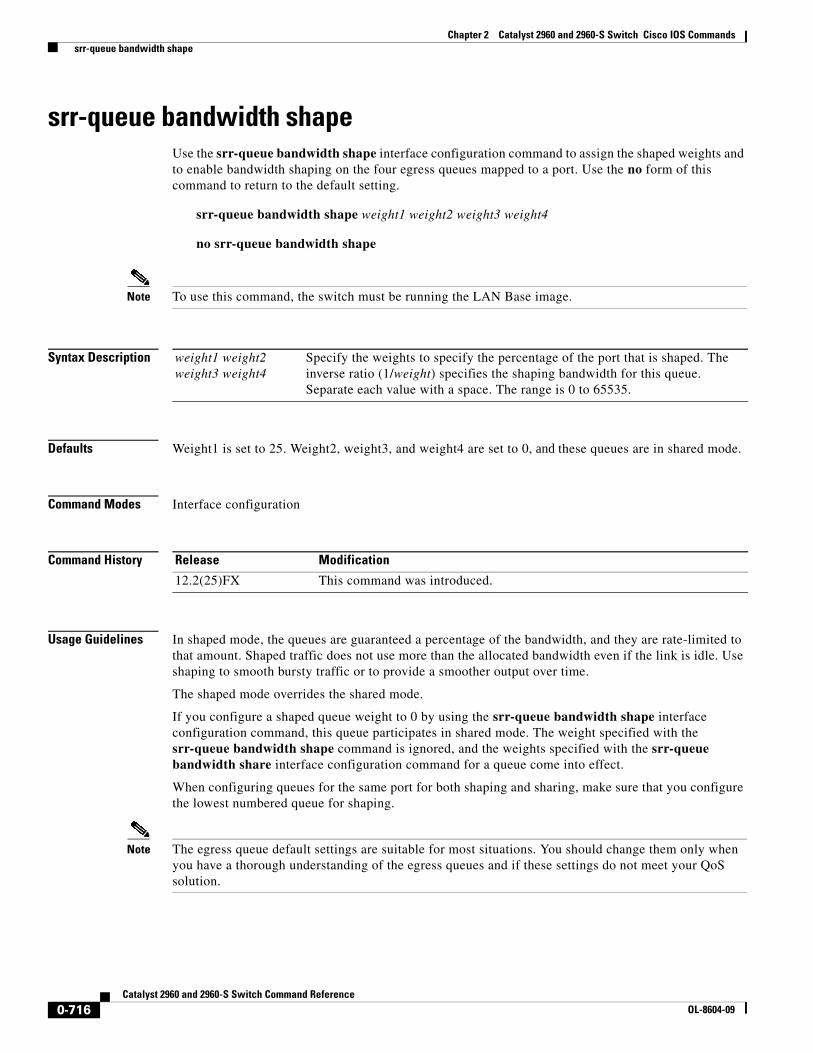
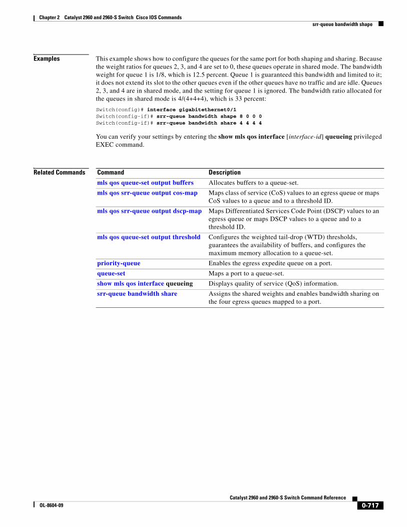
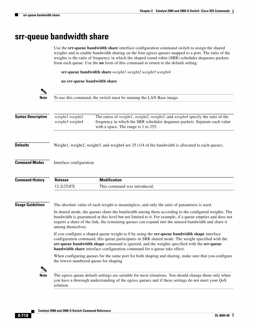
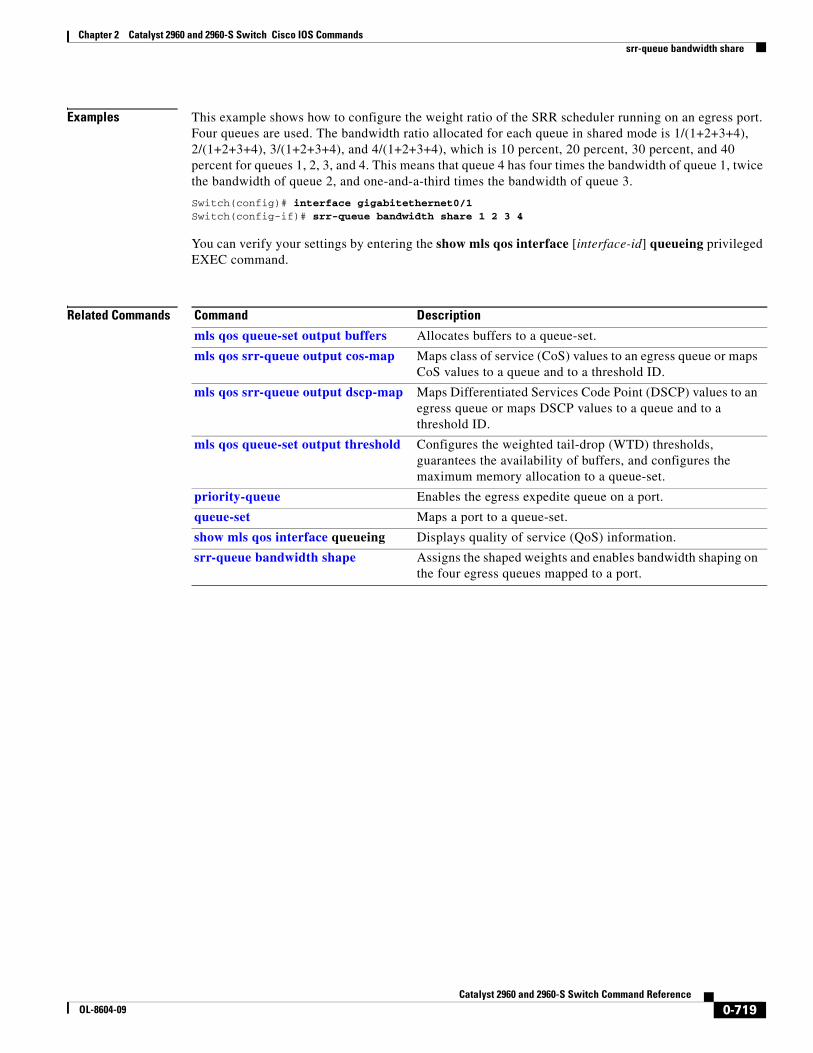
Chapter 2 Catalyst 2960 and 2960-S Switch Cisco IOS Commands shutdown 0-653 Catalyst 2960 and 2960-S Switch Command Reference OL-8604-09 0V] shutdown Use the shutdown interface configuration command to disable an interface. Use the no form of this command to restart a disabled interface. shutdown no shutdown Syntax Description This command has no arguments or keywords. Defaults The port is enabled (not shut down). Command Modes Interface configuration Command History Usage Guidelines The shutdown command causes a port to stop forwarding. You can enable the port with the no shutdown command. The no shutdown command has no effect if the port is a static-access port assigned to a VLAN that has been deleted, suspended, or shut down. The port must first be a member of an active VLAN before it can be re-enabled. The shutdown command disables all functions on the specified interface. This command also marks the interface as unavailable. To see if an interface is disabled, use the show interfaces privileged EXEC command. An interface that has been shut down is shown as administratively down in the display. Examples These examples show how to disable and re-enable a port: Switch(config)# interface gigabitethernet0/2 Switch(config-if)# shutdown Switch(config)# interface gigabitethernet0/2 Switch(config-if)# no shutdown You can verify your settings by entering the show interfaces privileged EXEC command. Related Commands Release Modification 12.2(25)FX This command was introduced. Command Description show interfaces Displays the statistical information specific to all interfaces or to a specific interface.
Transcript
Cisco IOS Commands
Chapter 2 Catalyst 2960 and 2960-S Switch 0 V ]
shutdown
shutdownUse the shutdown interface configuration command to disable an interface. Use the no form of this command to restart a disabled interface.
shutdown
no shutdown
Syntax Description This command has no arguments or keywords.
Defaults The port is enabled (not shut down).
Command Modes Interface configuration
Command History
Usage Guidelines The shutdown command causes a port to stop forwarding. You can enable the port with the no shutdown command.
The no shutdown command has no effect if the port is a static-access port assigned to a VLAN that has been deleted, suspended, or shut down. The port must first be a member of an active VLAN before it can be re-enabled.
The shutdown command disables all functions on the specified interface.
This command also marks the interface as unavailable. To see if an interface is disabled, use the show interfaces privileged EXEC command. An interface that has been shut down is shown as administratively down in the display.
Examples These examples show how to disable and re-enable a port:
shutdown vlanUse the shutdown vlan global configuration command to shut down (suspend) local traffic on the specified VLAN. Use the no form of this command to restart local traffic on the VLAN.
shutdown vlan vlan-id
no shutdown vlan vlan-id
Syntax Description
Defaults No default is defined.
Command Modes Global configuration
Command History
Usage Guidelines The shutdown vlan command does not change the VLAN information in the VTP database. The command shuts down local traffic, but the switch still advertises VTP information.
Examples This example shows how to shut down traffic on VLAN 2:
Switch(config)# shutdown vlan 2
You can verify your setting by entering the show vlan privileged EXEC command.
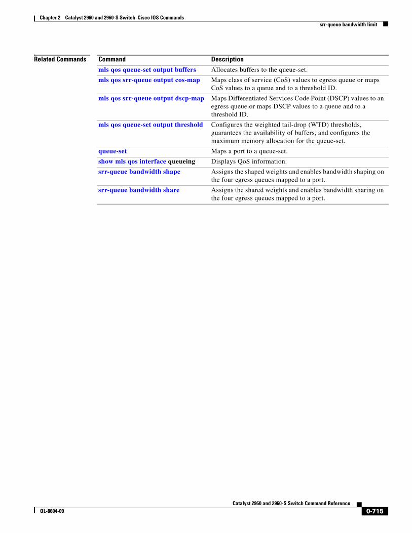
Related Commands
vlan-id ID of the VLAN to be locally shut down. The range is 2 to 1001. VLANs defined as default VLANs under the VLAN Trunking Protocol (VTP), as well as extended-range VLANs (greater than 1005) cannot be shut down. The default VLANs are 1 and 1002 to 1005.
Release Modification
12.2(25)FX This command was introduced.
Command Description
shutdown (config-vlan mode)
Shuts down local traffic on the VLAN when in config-VLAN mode (accessed by the vlan vlan-id global configuration command).
0-654Catalyst 2960 and 2960-S Switch Command Reference
small-frame violation rate Use the small-frame violation rate pps interface configuration command to configure the rate (threshold) for an interface to be error disabled when it receives VLAN-tagged packets that are small frames (67 bytes or less) at the specified rate. Use the no form of this command to return to the default setting.
small-frame violation rate pps
no small-frame violation rate pps
Syntax Description
Defaults This feature is disabled.
Command Modes Interface configuration
Command History
Usage Guidelines This command enables the rate (threshold) for a port to be error disabled when it receives small frames. Small frames are considered packets that are 67 frames or less.
Use the errdisable detect cause small-frame global configuration command to globally enable the small-frames threshold for each port.
You can configure the port to be automatically re-enabled by using the errdisable recovery cause small-frame global configuration command. You configure the recovery time by using the errdisable recovery interval interval global configuration command.
Examples This example shows how to enable the small-frame arrival rate feature so that the port is error disabled if incoming small frames arrived at 10,000 pps.
errdisable detect cause small-frame Allows any switch port to be put into the error-disabled state if an incoming frame is smaller than the minimum size and arrives at the specified rate (threshold).
errdisable recovery cause small-frame
Enables the recovery timer.
show interfaces Displays the interface settings on the switch, including input and output flow control.
0-656Catalyst 2960 and 2960-S Switch Command Reference
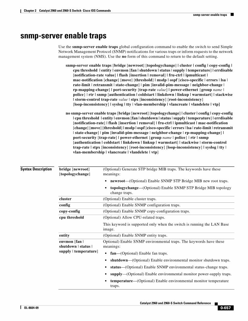
snmp-server enable trapsUse the snmp-server enable traps global configuration command to enable the switch to send Simple Network Management Protocol (SNMP) notifications for various traps or inform requests to the network management system (NMS). Use the no form of this command to return to the default setting.
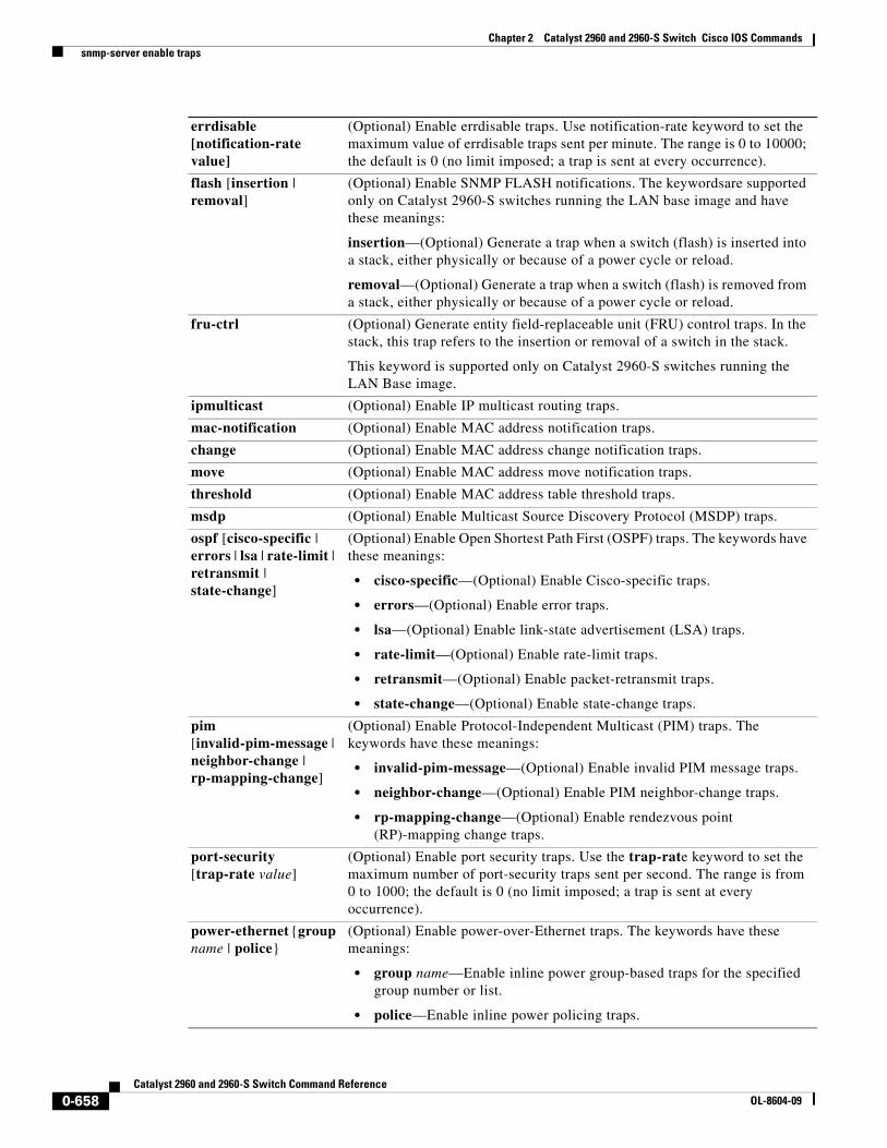
(Optional) Enable errdisable traps. Use notification-rate keyword to set the maximum value of errdisable traps sent per minute. The range is 0 to 10000; the default is 0 (no limit imposed; a trap is sent at every occurrence).
flash [insertion | removal]
(Optional) Enable SNMP FLASH notifications. The keywordsare supported only on Catalyst 2960-S switches running the LAN base image and have these meanings:
insertion—(Optional) Generate a trap when a switch (flash) is inserted into a stack, either physically or because of a power cycle or reload.
removal—(Optional) Generate a trap when a switch (flash) is removed from a stack, either physically or because of a power cycle or reload.
fru-ctrl (Optional) Generate entity field-replaceable unit (FRU) control traps. In the stack, this trap refers to the insertion or removal of a switch in the stack.
This keyword is supported only on Catalyst 2960-S switches running the LAN Base image.
ipmulticast (Optional) Enable IP multicast routing traps.
mac-notification (Optional) Enable MAC address notification traps.
change (Optional) Enable MAC address change notification traps.
move (Optional) Enable MAC address move notification traps.
threshold (Optional) Enable MAC address table threshold traps.
• rp-mapping-change—(Optional) Enable rendezvous point (RP)-mapping change traps.
port-security[trap-rate value]
(Optional) Enable port security traps. Use the trap-rate keyword to set the maximum number of port-security traps sent per second. The range is from 0 to 1000; the default is 0 (no limit imposed; a trap is sent at every occurrence).
power-ethernet {group name | police}
(Optional) Enable power-over-Ethernet traps. The keywords have these meanings:
• group name—Enable inline power group-based traps for the specified group number or list.
• police—Enable inline power policing traps.
0-658Catalyst 2960 and 2960-S Switch Command Reference
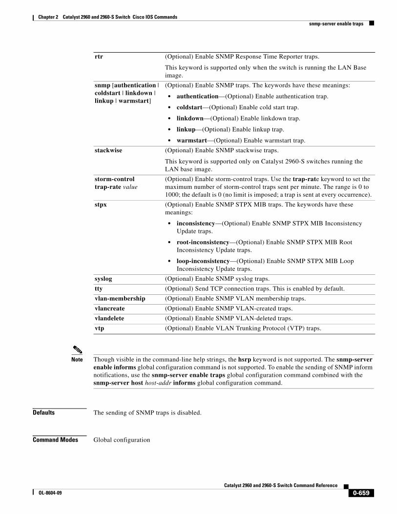
Note Though visible in the command-line help strings, the hsrp keyword is not supported. The snmp-server enable informs global configuration command is not supported. To enable the sending of SNMP inform notifications, use the snmp-server enable traps global configuration command combined with the snmp-server host host-addr informs global configuration command.
Defaults The sending of SNMP traps is disabled.
Command Modes Global configuration
rtr (Optional) Enable SNMP Response Time Reporter traps.
This keyword is supported only when the switch is running the LAN Base image.
This keyword is supported only on Catalyst 2960-S switches running the LAN base image.
storm-control trap-rate value
(Optional) Enable storm-control traps. Use the trap-rate keyword to set the maximum number of storm-control traps sent per minute. The range is 0 to 1000; the default is 0 (no limit is imposed; a trap is sent at every occurrence).
stpx (Optional) Enable SNMP STPX MIB traps. The keywords have these meanings:
Usage Guidelines Specify the host (NMS) that receives the traps by using the snmp-server host global configuration command. If no trap types are specified, all types are sent.
When supported, use the snmp-server enable traps command to enable sending of traps or informs.
Note Informs are not supported in SNMPv1.
To enable more than one type of trap, you must enter a separate snmp-server enable traps command for each trap type.
To set the CPU threshold notification types and values, use the process cpu threshold type global configuration command.
Examples This example shows how to send VTP traps to the NMS:
Switch(config)# snmp-server enable traps vtp
You can verify your setting by entering the show vtp status or the show running-config privileged EXEC command.
Related Commands
Release Modification
12.2(25)FX This command was introduced.
12.2(37)SE The errdisable notification-rate value keywords were added.
12.2(40)SE The change, move, and threshold keywords were added to the mac-notification option.
12.2(44)SE The power-ethernet {group name | police} keywords were added.
12.2(50)SE The cpu threshold keywords were added.
12.2(53)SE1 The flash [insertion | removal], fru-ctrl, and stackwise keywords were added on Catalyst 2960-S switches running the LAN base image.
Command Description
show running-config Displays the running configuration on the switch.
snmp-server host Specifies the host that receives SNMP traps.
0-660Catalyst 2960 and 2960-S Switch Command Reference
snmp-server host Use the snmp-server host global configuration command to specify the recipient (host) of a Simple Network Management Protocol (SNMP) notification operation. Use the no form of this command to remove the specified host.
• noauth (Default). The noAuthNoPriv security level. This is the default if the [auth | noauth | priv] keyword choice is not specified.
• priv (Optional). Enables Data Encryption Standard (DES) packet encryption (also called privacy).
Note The priv keyword is available only when the cryptographic (encrypted) software image is installed.
vrf vrf-instance (Optional) Virtual private network (VPN) routing instance and name for this host.
community-string Password-like community string sent with the notification operation. Though you can set this string by using the snmp-server host command, we recommend that you define this string by using the snmp-server community global configuration command before using the snmp-server host command.
Note The @ symbol is used for delimiting the context information. Avoid using the @ symbol as part of the SNMP community string when configuring this command.
0-661Catalyst 2960 and 2960-S Switch Command Reference
notification-type (Optional) Type of notification to be sent to the host. If no type is specified, all notifications are sent. The notification type can be one or more of the these keywords:
• bridge—Send SNMP Spanning Tree Protocol (STP) bridge MIB traps.
• cluster—Send cluster member status traps.
• config—Send SNMP configuration traps.
• copy-config—Send SNMP copy configuration traps.
• cpu threshold—Allow CPU-related traps. This keyword is supported only when the switch is running the LAN Base image.
• entity— Send SNMP entity traps.
• envmon—Send environmental monitor traps.
• errdisable—Send SNMP errdisable notifications.
• flash—Send SNMP FLASH notifications.
• fru-ctrl—Send entity FRU control traps. In the switch stack, this trap refers to the insertion or removal of a switch in the stack.
• hsrp—Send SNMP Hot Standby Router Protocol (HSRP) traps.
• ipmulticast—Send SNMP IP multicast routing traps.
• mac-notification—Send SNMP MAC notification traps.
Defaults This command is disabled by default. No notifications are sent.
If you enter this command with no keywords, the default is to send all trap types to the host. No informs are sent to this host.
If no version keyword is present, the default is Version 1.
If Version 3 is selected and no authentication keyword is entered, the default is the noauth (noAuthNoPriv) security level.
Command Modes Global configuration
Command History
Usage Guidelines SNMP notifications can be sent as traps or inform requests. Traps are unreliable because the receiver does not send acknowledgments when it receives traps. The sender cannot determine if the traps were received. However, an SNMP entity that receives an inform request acknowledges the message with an SNMP response PDU. If the sender never receives the response, the inform request can be sent again. Thus, informs are more likely to reach their intended destinations.
However, informs consume more resources in the agent and in the network. Unlike a trap, which is discarded as soon as it is sent, an inform request must be held in memory until a response is received or the request times out. Traps are also sent only once, but an inform might be retried several times. The retries increase traffic and contribute to a higher overhead on the network.
If you do not enter an snmp-server host command, no notifications are sent. To configure the switch to send SNMP notifications, you must enter at least one snmp-server host command. If you enter the command with no keywords, all trap types are enabled for the host. To enable multiple hosts, you must enter a separate snmp-server host command for each host. You can specify multiple notification types in the command for each host.
If a local user is not associated with a remote host, the switch does not send informs for the auth (authNoPriv) and the priv (authPriv) authentication levels.
When multiple snmp-server host commands are given for the same host and kind of notification (trap or inform), each succeeding command overwrites the previous command. Only the last snmp-server host command is in effect. For example, if you enter an snmp-server host inform command for a host and then enter another snmp-server host inform command for the same host, the second command replaces the first.
Release Modification
12.2(25)FX This command was introduced.
12.2(37)SE The errdisable notification-rate value keywords were added.
12.2(50)SE The cpu threshold keywords were added.
12.2(53)SE1 The fru-ctrl keyword was added only on the Catalyst 2960-S switch running the LAN base image.
0-663Catalyst 2960 and 2960-S Switch Command Reference
The snmp-server host command is used with the snmp-server enable traps global configuration command. Use the snmp-server enable traps command to specify which SNMP notifications are sent globally. For a host to receive most notifications, at least one snmp-server enable traps command and the snmp-server host command for that host must be enabled. Some notification types cannot be controlled with the snmp-server enable traps command. For example, some notification types are always enabled. Other notification types are enabled by a different command.
The no snmp-server host command with no keywords disables traps, but not informs, to the host. To disable informs, use the no snmp-server host informs command.
Examples This example shows how to configure a unique SNMP community string named comaccess for traps and prevent SNMP polling access with this string through access-list 10:
Switch(config)# snmp-server community comaccess ro 10Switch(config)# snmp-server host 172.20.2.160 comaccessSwitch(config)# access-list 10 deny any
This example shows how to send the SNMP traps to the host specified by the name myhost.cisco.com. The community string is defined as comaccess:
snmp trap mac-notification changeUse the snmp trap mac-notification change interface configuration command to enable the Simple Network Management Protocol (SNMP) MAC address change notification trap on a specific Layer 2 interface. Use the no form of this command to return to the default setting.
no snmp trap mac-notification change {added | removed}
Syntax Description
Defaults By default, the traps for both address addition and address removal are disabled.
Command Modes Interface configuration
Command History
Usage Guidelines Even though you enable the notification trap for a specific interface by using the snmp trap mac-notification change command, the trap is generated only when you enter the snmp-server enable traps mac-notification change and the mac address-table notification change global configuration commands.
Examples This example shows how to enable the MAC notification trap when a MAC address is added to a port:
clear mac address-table notification Clears the MAC address notification global counters.
mac address-table notification Enables the MAC address notification feature.
show mac address-table notification Displays the MAC address notification settings for all interfaces or on the specified interface when the interface keyword is appended.
snmp-server enable traps Sends the SNMP MAC notification traps when the mac-notification keyword is appended.
0-666Catalyst 2960 and 2960-S Switch Command Reference
spanning-tree backbonefastUse the spanning-tree backbonefast global configuration command to enable the BackboneFast feature. Use the no form of the command to return to the default setting.
spanning-tree backbonefast
no spanning-tree backbonefast
Syntax Description This command has no arguments or keywords.
Defaults BackboneFast is disabled.
Command Modes Global configuration
Command History
Usage Guidelines You can configure the BackboneFast feature for rapid PVST+ or for multiple spanning-tree (MST) mode, but the feature remains disabled (inactive) until you change the spanning-tree mode to PVST+.
BackboneFast starts when a root port or blocked port on a switch receives inferior BPDUs from its designated switch. An inferior BPDU identifies a switch that declares itself as both the root bridge and the designated switch. When a switch receives an inferior BPDU, it means that a link to which the switch is not directly connected (an indirect link) has failed (that is, the designated switch has lost its connection to the root switch. If there are alternate paths to the root switch, BackboneFast causes the maximum aging time on the interfaces on which it received the inferior BPDU to expire and allows a blocked port to move immediately to the listening state. BackboneFast then transitions the interface to the forwarding state. For more information, see the software configuration guide for this release.
Enable BackboneFast on all supported switches to allow the detection of indirect link failures and to start the spanning-tree reconfiguration sooner.
Examples This example shows how to enable BackboneFast on the switch:
Switch(config)# spanning-tree backbonefast
You can verify your setting by entering the show spanning-tree summary privileged EXEC command.
Related Commands
Release Modification
12.2(25)FX This command was introduced.
Command Description
show spanning-tree summary Displays a summary of the spanning-tree interface states.
0-667Catalyst 2960 and 2960-S Switch Command Reference
spanning-tree bpdufilter Use the spanning-tree bpdufilter interface configuration command to prevent an interface from sending or receiving bridge protocol data units (BPDUs). Use the no form of this command to return to the default setting.
spanning-tree bpdufilter {disable | enable}
no spanning-tree bpdufilter
Syntax Description
Defaults BPDU filtering is disabled.
Command Modes Interface configuration
Command History
Usage Guidelines You can enable the BPDU filtering feature when the switch is operating in the per-VLAN spanning-tree plus (PVST+), rapid-PVST+, or the multiple spanning-tree (MST) mode.
Caution Enabling BPDU filtering on an interface is the same as disabling spanning tree on it and can result in spanning-tree loops.
You can globally enable BPDU filtering on all Port Fast-enabled interfaces by using the spanning-tree portfast bpdufilter default global configuration command.
You can use the spanning-tree bpdufilter interface configuration command to override the setting of the spanning-tree portfast bpdufilter default global configuration command.
Examples This example shows how to enable the BPDU filtering feature on a port:
show running-config Displays the current operating configuration.
spanning-tree portfast (global configuration)
Globally enables the BPDU filtering or the BPDU guard feature on Port Fast-enabled interface or enables the Port Fast feature on all nontrunking interfaces.
spanning-tree portfast (interface configuration)
Enables the Port Fast feature on an interface and all its associated VLANs.
0-669Catalyst 2960 and 2960-S Switch Command Reference
spanning-tree bpduguard Use the spanning-tree bpduguard interface configuration command to put an interface in the error-disabled state when it receives a bridge protocol data unit (BPDU). Use the no form of this command to return to the default setting.
spanning-tree bpduguard {disable | enable}
no spanning-tree bpduguard
Syntax Description
Defaults BPDU guard is disabled.
Command Modes Interface configuration
Command History
Usage Guidelines The BPDU guard feature provides a secure response to invalid configurations because you must manually put the interface back in service. Use the BPDU guard feature in a service-provider network to prevent an interface from being included in the spanning-tree topology.
You can enable the BPDU guard feature when the switch is operating in the per-VLAN spanning-tree plus (PVST+), rapid-PVST+, or the multiple spanning-tree (MST) mode.
You can globally enable BPDU guard on all Port Fast-enabled interfaces by using the spanning-tree portfast bpduguard default global configuration command.
You can use the spanning-tree bpduguard interface configuration command to override the setting of the spanning-tree portfast bpduguard default global configuration command.
Examples This example shows how to enable the BPDU guard feature on a port:
show running-config Displays the current operating configuration.
spanning-tree portfast (global configuration)
Globally enables the BPDU filtering or the BPDU guard feature on Port Fast-enabled interfaces or enables the Port Fast feature on all nontrunking interfaces.
spanning-tree portfast (interface configuration)
Enables the Port Fast feature on an interface and all its associated VLANs.
0-671Catalyst 2960 and 2960-S Switch Command Reference
spanning-tree costUse the spanning-tree cost interface configuration command to set the path cost for spanning-tree calculations. If a loop occurs, spanning tree considers the path cost when selecting an interface to place in the forwarding state. Use the no form of this command to return to the default setting.
spanning-tree [vlan vlan-id] cost cost
no spanning-tree [vlan vlan-id] cost
Syntax Description
Defaults The default path cost is computed from the interface bandwidth setting. These are the IEEE default path cost values:
• 1000 Mb/s—4
• 100 Mb/s—19
• 10 Mb/s—100
Command Modes Interface configuration
Command History
Usage Guidelines When you configure the cost, higher values represent higher costs.
If you configure an interface with both the spanning-tree vlan vlan-id cost cost command and the spanning-tree cost cost command, the spanning-tree vlan vlan-id cost cost command takes effect.
Examples This example shows how to set the path cost to 250 on a port:
You can verify your settings by entering the show spanning-tree interface interface-id privileged EXEC command.
vlan vlan-id (Optional) VLAN range associated with a spanning-tree instance. You can specify a single VLAN identified by VLAN ID number, a range of VLANs separated by a hyphen, or a series of VLANs separated by a comma. The range is 1 to 4094.
cost Path cost. The range is 1 to 200000000, with higher values meaning higher costs.
Release Modification
12.2(25)FX This command was introduced.
0-672Catalyst 2960 and 2960-S Switch Command Reference
spanning-tree etherchannel guard misconfigUse the spanning-tree etherchannel guard misconfig global configuration command to display an error message when the switch detects an EtherChannel misconfiguration. Use the no form of this command to disable the feature.
spanning-tree etherchannel guard misconfig
no spanning-tree etherchannel guard misconfig
Syntax Description This command has no arguments or keywords.
Defaults EtherChannel guard is enabled on the switch.
Command Modes Global configuration
Command History
Usage Guidelines When the switch detects an EtherChannel misconfiguration, this error message appears:
PM-4-ERR_DISABLE: Channel-misconfig error detected on [chars], putting [chars] in err-disable state.
To show switch ports that are in the misconfigured EtherChannel, use the show interfaces status err-disabled privileged EXEC command. To verify the EtherChannel configuration on a remote device, use the show etherchannel summary privileged EXEC command on the remote device.
When a port is in the error-disabled state because of an EtherChannel misconfiguration, you can bring it out of this state by entering the errdisable recovery cause channel-misconfig global configuration command, or you can manually re-enable it by entering the shutdown and no shut down interface configuration commands.
Examples This example shows how to enable the EtherChannel guard misconfiguration feature:
spanning-tree extend system-idUse the spanning-tree extend system-id global configuration command to enable the extended system ID feature.
spanning-tree extend system-id
Note Though visible in the command-line help strings, the no version of this command is not supported. You cannot disable the extended system ID feature.
Syntax Description This command has no arguments or keywords.
Defaults The extended system ID is enabled.
Command Modes Global configuration
Command History
Usage Guidelines The switch supports the IEEE 802.1t spanning-tree extensions. Some of the bits previously used for the switch priority are now used for the extended system ID (VLAN identifier for the per-VLAN spanning-tree plus [PVST+] and rapid PVST+ or as an instance identifier for the multiple spanning tree [MST]).
The spanning tree uses the extended system ID, the switch priority, and the allocated spanning-tree MAC address to make the bridge ID unique for each VLAN or multiple spanning-tree instance. Because the switch stack appears as a single switch to the rest of the network, all switches in the stack use the same bridge ID for a given spanning tree. If the stack master fails, the stack members recalculate their bridge IDs of all running spanning trees based on the new MAC address of the stack master.
Support for the extended system ID affects how you manually configure the root switch, the secondary root switch, and the switch priority of a VLAN. For more information, see the “spanning-tree mst root” and the “spanning-tree vlan” sections.
If your network consists of switches that do not support the extended system ID and switches that do support it, it is unlikely that the switch with the extended system ID support will become the root switch. The extended system ID increases the switch priority value every time the VLAN number is greater than the priority of the connected switches.
Release Modification
12.2(25)FX This command was introduced.
0-676Catalyst 2960 and 2960-S Switch Command Reference
spanning-tree guardUse the spanning-tree guard interface configuration command to enable root guard or loop guard on all the VLANs associated with the selected interface. Root guard restricts which interface is allowed to be the spanning-tree root port or the path-to-the root for the switch. Loop guard prevents alternate or root ports from becoming designated ports when a failure creates a unidirectional link. Use the no form of this command to return to the default setting.
spanning-tree guard {loop | none | root}
no spanning-tree guard
Syntax Description
Defaults Root guard is disabled.
Loop guard is configured according to the spanning-tree loopguard default global configuration command (globally disabled).
Command Modes Interface configuration
Command History
Usage Guidelines You can enable root guard or loop guard when the switch is operating in the per-VLAN spanning-tree plus (PVST+), rapid-PVST+, or the multiple spanning-tree (MST) mode.
When root guard is enabled, if spanning-tree calculations cause an interface to be selected as the root port, the interface transitions to the root-inconsistent (blocked) state to prevent the customer’s switch from becoming the root switch or being in the path to the root. The root port provides the best path from the switch to the root switch.
When the no spanning-tree guard or the no spanning-tree guard none command is entered, root guard is disabled for all VLANs on the selected interface. If this interface is in the root-inconsistent (blocked) state, it automatically transitions to the listening state.
Do not enable root guard on interfaces that will be used by the UplinkFast feature. With UplinkFast, the backup interfaces (in the blocked state) replace the root port in the case of a failure. However, if root guard is also enabled, all the backup interfaces used by the UplinkFast feature are placed in the root-inconsistent state (blocked) and prevented from reaching the forwarding state. The UplinkFast feature is not available when the switch is operating in the rapid-PVST+ or MST mode.
Loop guard is most effective when it is configured on the entire switched network. When the switch is operating in PVST+ or rapid-PVST+ mode, loop guard prevents alternate and root ports from becoming designated ports, and spanning tree does not send bridge protocol data units (BPDUs) on root or alternate
loop Enable loop guard.
none Disable root guard or loop guard.
root Enable root guard.
Release Modification
12.2(25)FX This command was introduced.
0-678Catalyst 2960 and 2960-S Switch Command Reference
ports. When the switch is operating in MST mode, BPDUs are not sent on nonboundary interfaces if the interface is blocked by loop guard in all MST instances. On a boundary interface, loop guard blocks the interface in all MST instances.
To disable root guard or loop guard, use the spanning-tree guard none interface configuration command. You cannot enable both root guard and loop guard at the same time.
You can override the setting of the spanning-tree loopguard default global configuration command by using the spanning-tree guard loop interface configuration command.
Examples This example shows how to enable root guard on all the VLANs associated with the specified port:
You can verify your settings by entering the show running-config privileged EXEC command.
Related Commands Command Description
show running-config Displays the current operating configuration.
spanning-tree cost Sets the path cost for spanning-tree calculations.
spanning-tree loopguard default Prevents alternate or root ports from becoming designated ports because of a failure that leads to a unidirectional link.
spanning-tree mst cost Configures the path cost for MST calculations.
spanning-tree mst port-priority Configures an interface priority.
spanning-tree mst root Configures the MST root switch priority and timers based on the network diameter.
spanning-tree port-priority Configures an interface priority.
spanning-tree vlan priority Sets the switch priority for the specified spanning-tree instance.
0-679Catalyst 2960 and 2960-S Switch Command Reference
spanning-tree link-type Use the spanning-tree link-type interface configuration command to override the default link-type setting, which is determined by the duplex mode of the interface, and to enable rapid spanning-tree transitions to the forwarding state. Use the no form of this command to return to the default setting.
spanning-tree link-type {point-to-point | shared}
no spanning-tree link-type
Syntax Description
Defaults The switch derives the link type of an interface from the duplex mode. A full-duplex interface is considered a point-to-point link, and a half-duplex interface is considered a shared link.
Command Modes Interface configuration
Command History
Usage Guidelines You can override the default setting of the link type by using the spanning-tree link-type command. For example, a half-duplex link can be physically connected point-to-point to a single interface on a remote switch running the Multiple Spanning Tree Protocol (MSTP) or the rapid per-VLAN spanning-tree plus (rapid-PVST+) protocol and be enabled for rapid transitions.
Examples This example shows how to specify the link type as shared (regardless of the duplex setting) and to prevent rapid transitions to the forwarding state:
Switch(config-if)# spanning-tree link-type shared
You can verify your setting by entering the show spanning-tree mst interface interface-id or the show spanning-tree interface interface-id privileged EXEC command.
point-to-point Specify that the link type of an interface is point-to-point.
shared Specify that the link type of an interface is shared.
Release Modification
12.2(25)FX This command was introduced.
0-680Catalyst 2960 and 2960-S Switch Command Reference
clear spanning-tree detected-protocols Restarts the protocol migration process (force the renegotiation with neighboring switches) on all interfaces or on the specified interface.
show spanning-tree interface interface-id
Displays spanning-tree state information for the specified interface.
show spanning-tree mst interface interface-id
Displays MST information for the specified interface.
0-681Catalyst 2960 and 2960-S Switch Command Reference
spanning-tree loopguard defaultUse the spanning-tree loopguard default global configuration command to prevent alternate or root ports from becoming designated ports because of a failure that leads to a unidirectional link. Use the no form of this command to return to the default setting.
spanning-tree loopguard default
no spanning-tree loopguard default
Syntax Description This command has no arguments or keywords.
Defaults Loop guard is disabled.
Command Modes Global configuration
Command History
Usage Guidelines You can enable the loop guard feature when the switch is operating in the per-VLAN spanning-tree plus (PVST+), rapid-PVST+, or the multiple spanning-tree (MST) mode.
Loop guard is most effective when it is configured on the entire switched network. When the switch is operating in PVST+ or rapid-PVST+ mode, loop guard prevents alternate and root ports from becoming designated ports, and spanning tree does not send bridge protocol data units (BPDUs) on root or alternate ports. When the switch is operating in MST mode, BPDUs are not sent on nonboundary interfaces if the interface is blocked by loop guard in all MST instances. On a boundary interface, loop guard blocks the interface in all MST instances.
Loop guard operates only on interfaces that the spanning tree identifies as point-to-point.
You can override the setting of the spanning-tree loopguard default global configuration command by using the spanning-tree guard loop interface configuration command.
Examples This example shows how to globally enable loop guard:
Switch(config)# spanning-tree loopguard default
You can verify your settings by entering the show running-config privileged EXEC command.
Related Commands
Release Modification
12.2(25)FX This command was introduced.
Command Description
show running-config Displays the current operating configuration.
spanning-tree guard loop Enables the loop guard feature on all the VLANs associated with the specified interface.
0-682Catalyst 2960 and 2960-S Switch Command Reference
spanning-tree mode Use the spanning-tree mode global configuration command to enable per-VLAN spanning-tree plus (PVST+), rapid PVST+, or multiple spanning tree (MST) on your switch. Use the no form of this command to return to the default setting.
spanning-tree mode {mst | pvst | rapid-pvst}
no spanning-tree mode
Syntax Description
Defaults The default mode is PVST+.
Command Modes Global configuration
Command History
Usage Guidelines The switch supports PVST+, rapid PVST+, and MSTP, but only one version can be active at any time: All VLANs run PVST+, all VLANs run rapid PVST+, or all VLANs run MSTP. All stack members run the same version of spanning-tree.
When you enable the MST mode, RSTP is automatically enabled.
Caution Changing spanning-tree modes can disrupt traffic because all spanning-tree instances are stopped for the previous mode and restarted in the new mode.
Examples This example shows to enable MST and RSTP on the switch:
Switch(config)# spanning-tree mode mst
This example shows to enable rapid PVST+ on the switch:
Switch(config)# spanning-tree mode rapid-pvst
You can verify your setting by entering the show running-config privileged EXEC command.
mst Enable MST and Rapid Spanning Tree Protocol (RSTP) (based on IEEE 802.1s and IEEE 802.1w).
pvst Enable PVST+ (based on IEEE 802.1D).
rapid-pvst Enable rapid PVST+ (based on IEEE 802.1w).
Release Modification
12.2(25)FX This command was introduced.
0-683Catalyst 2960 and 2960-S Switch Command Reference
spanning-tree mst configuration Use the spanning-tree mst configuration global configuration command to enter multiple spanning-tree (MST) configuration mode through which you configure the MST region. Use the no form of this command to return to the default settings.
spanning-tree mst configuration
no spanning-tree mst configuration
Syntax Description This command has no arguments or keywords.
Defaults The default mapping is that all VLANs are mapped to the common and internal spanning-tree (CIST) instance (instance 0).
The default name is an empty string.
The revision number is 0.
Command Modes Global configuration
Command History
Usage Guidelines The spanning-tree mst configuration command enables the MST configuration mode. These configuration commands are available:
• abort: exits the MST region configuration mode without applying configuration changes.
• exit: exits the MST region configuration mode and applies all configuration changes.
• instance instance-id vlan vlan-range: maps VLANs to an MST instance. The range for the instance-id is 1 to 4094. The range for vlan-range is 1 to 4094. You can specify a single VLAN identified by VLAN ID number, a range of VLANs separated by a hyphen, or a series of VLANs separated by a comma.
• name name: sets the configuration name. The name string has a maximum length of 32 characters and is case sensitive.
• no: negates the instance, name, and revision commands or sets them to their defaults.
• private-vlan: Though visible in the command-line help strings, this command is not supported.
• revision version: sets the configuration revision number. The range is 0 to 65535.
• show [current | pending]: displays the current or pending MST region configuration.
In MST mode, the switch stack supports up to 65 MST instances. The number of VLANs that can be mapped to a particular MST instance is unlimited.
Release Modification
12.2(25)FX This command was introduced.
12.2(25)SED The instance-id range changed to 1 to 4094.
0-685Catalyst 2960 and 2960-S Switch Command Reference
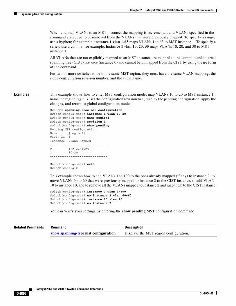
When you map VLANs to an MST instance, the mapping is incremental, and VLANs specified in the command are added to or removed from the VLANs that were previously mapped. To specify a range, use a hyphen; for example, instance 1 vlan 1-63 maps VLANs 1 to 63 to MST instance 1. To specify a series, use a comma; for example, instance 1 vlan 10, 20, 30 maps VLANs 10, 20, and 30 to MST instance 1.
All VLANs that are not explicitly mapped to an MST instance are mapped to the common and internal spanning tree (CIST) instance (instance 0) and cannot be unmapped from the CIST by using the no form of the command.
For two or more switches to be in the same MST region, they must have the same VLAN mapping, the same configuration revision number, and the same name.
Examples This example shows how to enter MST configuration mode, map VLANs 10 to 20 to MST instance 1, name the region region1, set the configuration revision to 1, display the pending configuration, apply the changes, and return to global configuration mode:
This example shows how to add VLANs 1 to 100 to the ones already mapped (if any) to instance 2, to move VLANs 40 to 60 that were previously mapped to instance 2 to the CIST instance, to add VLAN 10 to instance 10, and to remove all the VLANs mapped to instance 2 and map them to the CIST instance:
Switch(config-mst)# instance 2 vlan 1-100Switch(config-mst)# no instance 2 vlan 40-60Switch(config-mst)# instance 10 vlan 10Switch(config-mst)# no instance 2
You can verify your settings by entering the show pending MST configuration command.
Related Commands Command Description
show spanning-tree mst configuration Displays the MST region configuration.
0-686Catalyst 2960 and 2960-S Switch Command Reference
spanning-tree mst cost Use the spanning-tree mst cost interface configuration command to set the path cost for multiple spanning-tree (MST) calculations. If a loop occurs, spanning tree considers the path cost when selecting an interface to put in the forwarding state. Use the no form of this command to return to the default setting.
spanning-tree mst instance-id cost cost
no spanning-tree mst instance-id cost
Syntax Description
Defaults The default path cost is computed from the interface bandwidth setting. These are the IEEE default path cost values:
• 1000 Mb/s—20000
• 100 Mb/s—200000
• 10 Mb/s—2000000
Command Modes Interface configuration
Command History
Usage Guidelines When you configure the cost, higher values represent higher costs.
Examples This example shows how to set a path cost of 250 on a port associated with instances 2 and 4:
You can verify your settings by entering the show spanning-tree mst interface interface-id privileged EXEC command.
instance-id Range of spanning-tree instances. You can specify a single instance, a range of instances separated by a hyphen, or a series of instances separated by a comma. The range is 0 to 4094.
cost Path cost is 1 to 200000000, with higher values meaning higher costs.
Release Modification
12.2(25)FX This command was introduced.
12.2(25)SED The instance-id range changed to1 to 4094.
0-687Catalyst 2960 and 2960-S Switch Command Reference
spanning-tree mst forward-time Use the spanning-tree mst forward-time global configuration command to set the forward-delay time for all multiple spanning-tree (MST) instances. The forwarding time specifies how long each of the listening and learning states last before the interface begins forwarding. Use the no form of this command to return to the default setting.
spanning-tree mst forward-time seconds
no spanning-tree mst forward-time
Syntax Description
Defaults The default is 15 seconds.
Command Modes Global configuration
Command History
Usage Guidelines Changing the spanning-tree mst forward-time command affects all spanning-tree instances.
Examples This example shows how to set the spanning-tree forwarding time to 18 seconds for all MST instances:
Switch(config)# spanning-tree mst forward-time 18
You can verify your setting by entering the show spanning-tree mst privileged EXEC command.
Related Commands
seconds Length of the listening and learning states. The range is 4 to 30 seconds.
Release Modification
12.2(25)FX This command was introduced.
Command Description
show spanning-tree mst Displays MST information.
spanning-tree mst hello-time Sets the interval between hello bridge protocol data units (BPDUs) sent by root switch configuration messages.
spanning-tree mst max-age Sets the interval between messages that the spanning tree receives from the root switch.
spanning-tree mst max-hops Sets the number of hops in a region before the BPDU is discarded.
0-689Catalyst 2960 and 2960-S Switch Command Reference
spanning-tree mst hello-time Use the spanning-tree mst hello-time global configuration command to set the interval between hello bridge protocol data units (BPDUs) sent by root switch configuration messages. Use the no form of this command to return to the default setting.
spanning-tree mst hello-time seconds
no spanning-tree mst hello-time
Syntax Description
Defaults The default is 2 seconds.
Command Modes Global configuration
Command History
Usage Guidelines After you set the spanning-tree mst max-age seconds global configuration command, if a switch does not receive BPDUs from the root switch within the specified interval, the switch recomputes the spanning-tree topology. The max-age setting must be greater than the hello-time setting.
Changing the spanning-tree mst hello-time command affects all spanning-tree instances.
Examples This example shows how to set the spanning-tree hello time to 3 seconds for all multiple spanning-tree (MST) instances:
Switch(config)# spanning-tree mst hello-time 3
You can verify your setting by entering the show spanning-tree mst privileged EXEC command.
Related Commands
seconds Interval between hello BPDUs sent by root switch configuration messages. The range is 1 to 10 seconds.
Release Modification
12.2(25)FX This command was introduced.
Command Description
show spanning-tree mst Displays MST information.
spanning-tree mst forward-time
Sets the forward-delay time for all MST instances.
spanning-tree mst max-age Sets the interval between messages that the spanning tree receives from the root switch.
spanning-tree mst max-hops Sets the number of hops in a region before the BPDU is discarded.
0-690Catalyst 2960 and 2960-S Switch Command Reference
spanning-tree mst max-age Use the spanning-tree mst max-age global configuration command to set the interval between messages that the spanning tree receives from the root switch. If a switch does not receive a bridge protocol data unit (BPDU) message from the root switch within this interval, it recomputes the spanning-tree topology. Use the no form of this command to return to the default setting.
spanning-tree mst max-age seconds
no spanning-tree mst max-age
Syntax Description
Defaults The default is 20 seconds.
Command Modes Global configuration
Command History
Usage Guidelines After you set the spanning-tree mst max-age seconds global configuration command, if a switch does not receive BPDUs from the root switch within the specified interval, the switch recomputes the spanning-tree topology. The max-age setting must be greater than the hello-time setting.
Changing the spanning-tree mst max-age command affects all spanning-tree instances.
Examples This example shows how to set the spanning-tree max-age to 30 seconds for all multiple spanning-tree (MST) instances:
Switch(config)# spanning-tree mst max-age 30
You can verify your setting by entering the show spanning-tree mst privileged EXEC command.
Related Commands
seconds Interval between messages the spanning tree receives from the root switch. The range is 6 to 40 seconds.
Release Modification
12.2(25)FX This command was introduced.
Command Description
show spanning-tree mst Displays MST information.
spanning-tree mst forward-time Sets the forward-delay time for all MST instances.
spanning-tree mst hello-time Sets the interval between hello BPDUs sent by root switch configuration messages.
spanning-tree mst max-hops Sets the number of hops in a region before the BPDU is discarded.
0-691Catalyst 2960 and 2960-S Switch Command Reference
spanning-tree mst max-hops Use the spanning-tree mst max-hops global configuration command to set the number of hops in a region before the bridge protocol data unit (BPDU) is discarded and the information held for an interface is aged. Use the no form of this command to return to the default setting.
spanning-tree mst max-hops hop-count
no spanning-tree mst max-hops
Syntax Description
Defaults The default is 20 hops.
Command Modes Global configuration
Command History
Usage Guidelines The root switch of the instance always sends a BPDU (or M-record) with a cost of 0 and the hop count set to the maximum value. When a switch receives this BPDU, it decrements the received remaining hop count by one and propagates the decremented count as the remaining hop count in the generated M-records. A switch discards the BPDU and ages the information held for the interface when the count reaches 0.
Changing the spanning-tree mst max-hops command affects all spanning-tree instances.
Examples This example shows how to set the spanning-tree max-hops to 10 for all multiple spanning-tree (MST) instances:
Switch(config)# spanning-tree mst max-hops 10
You can verify your setting by entering the show spanning-tree mst privileged EXEC command.
hop-count Number of hops in a region before the BPDU is discarded. The range is 1 to 255 hops.
Release Modification
12.2(25)FX This command was introduced.
12.2(25)SED The hop-count range changed to 1 to 255.
0-692Catalyst 2960 and 2960-S Switch Command Reference
spanning-tree mst port-priority Use the spanning-tree mst port-priority interface configuration command to configure an interface priority. If a loop occurs, the Multiple Spanning Tree Protocol (MSTP) can find the interface to put in the forwarding state. Use the no form of this command to return to the default setting.
Usage Guidelines You can assign higher priority values (lower numerical values) to interfaces that you want selected first and lower priority values (higher numerical values) that you want selected last. If all interfaces have the same priority value, the multiple spanning tree (MST) puts the interface with the lowest interface number in the forwarding state and blocks other interfaces.
If your switch is a member of a switch stack, you must use the spanning-tree mst [instance-id] cost cost interface configuration command instead of the spanning-tree mst [instance vlan-id] port-priority priority interface configuration command to select an interface to put in the forwarding state. Assign lower cost values to interfaces that you want selected first and higher cost values to interfaces that you want selected last.
Examples This example shows how to increase the likelihood that the interface associated with spanning-tree instances 20 and 22 is placed into the forwarding state if a loop occurs:
You can verify your settings by entering the show spanning-tree mst interface interface-id privileged EXEC command.
instance-id Range of spanning-tree instances. You can specify a single instance, a range of instances separated by a hyphen, or a series of instances separated by a comma. The range is 0 to 4094.
priority The range is 0 to 240 in increments of 16. Valid priority values are 0, 16, 32, 48, 64, 80, 96, 112, 128, 144, 160, 176, 192, 208, 224, and 240. All other values are rejected. The lower the number, the higher the priority.
Release Modification
12.2(25)FX This command was introduced.
12.2(25)SED The instance-id range changed to 1 to 4094.
0-694Catalyst 2960 and 2960-S Switch Command Reference
spanning-tree mst pre-standardUse the spanning-tree mst pre-standard interface configuration command to configure a port to send only prestandard bridge protocol data units (BPDUs).
spanning-tree mst pre-standard
no spanning-tree mst pre-standard
Syntax Description This command has no arguments or keywords.
Command Default The default state is automatic detection of prestandard neighbors.
Command Modes Interface configuration
Command History
Usage Guidelines The port can accept both prestandard and standard BPDUs. If the neighbor types are mismatched, only the common and internal spanning tree (CIST) runs on this interface.
Note If a switch port is connected to a switch running prestandard Cisco IOS software, you must use the spanning-tree mst pre-standard interface configuration command on the port. If you do not configure the port to send only prestandard BPDUs, the Multiple STP (MSTP) performance might diminish.
When the port is configured to automatically detect prestandard neighbors, the prestandard flag always appears in the show spanning-tree mst commands.
Examples This example shows how to configure a port to send only prestandard BPDUs:
Switch(config-if)# spanning-tree mst pre-standard
You can verify your settings by entering the show spanning-tree mst privileged EXEC command.
Related Commands
Release Modification
12.2(25)SED This command was introduced.
Command Description
show spanning-tree mst instance-id Displays multiple spanning-tree (MST) information, including the prestandard flag, for the specified interface.
0-696Catalyst 2960 and 2960-S Switch Command Reference
spanning-tree mst priority Use the spanning-tree mst priority global configuration command to set the switch priority for the specified spanning-tree instance. Use the no form of this command to return to the default setting.
spanning-tree mst instance-id priority priority
no spanning-tree mst instance-id priority
Syntax Description
Defaults The default is 32768.
Command Modes Global configuration
Command History
Examples This example shows how to set the spanning-tree priority to 8192 for multiple spanning-tree instances (MST) 20 to 21:
You can verify your settings by entering the show spanning-tree mst instance-id privileged EXEC command.
Related Commands
instance-id Range of spanning-tree instances. You can specify a single instance, a range of instances separated by a hyphen, or a series of instances separated by a comma. The range is 0 to 4094.
priority Set the switch priority for the specified spanning-tree instance. This setting affects the likelihood that the switch is selected as the root switch. A lower value increases the probability that the switch is selected as the root switch.
The range is 0 to 61440 in increments of 4096. Valid priority values are 0, 4096, 8192, 12288, 16384, 20480, 24576, 28672, 32768, 36864, 40960, 45056, 49152, 53248, 57344, and 61440. All other values are rejected.
Release Modification
12.2(25)FX This command was introduced.
12.2(25)SED The instance-id range changed to 1 to 4094.
Command Description
show spanning-tree mst instance-id Displays MST information for the specified interface.
spanning-tree mst cost Sets the path cost for MST calculations.
spanning-tree mst port-priority Configures an interface priority.
0-697Catalyst 2960 and 2960-S Switch Command Reference
spanning-tree mst root Use the spanning-tree mst root global configuration command to configure the multiple spanning-tree (MST) root switch priority and timers based on the network diameter. Use the no form of this command to return to the default settings.
Defaults The primary root switch priority is 24576.
The secondary root switch priority is 28672.
The hello time is 2 seconds.
Command Modes Global configuration
Command History
Usage Guidelines Use the spanning-tree mst instance-id root command only on backbone switches.
When you enter the spanning-tree mst instance-id root command, the software tries to set a high enough priority to make this switch the root of the spanning-tree instance. Because of the extended system ID support, the switch sets the switch priority for the instance to 24576 if this value will cause this switch to become the root for the specified instance. If any root switch for the specified instance has a switch priority lower than 24576, the switch sets its own priority to 4096 less than the lowest switch priority. (4096 is the value of the least-significant bit of a 4-bit switch priority value.)
instance-id Range of spanning-tree instances. You can specify a single instance, a range of instances separated by a hyphen, or a series of instances separated by a comma. The range is 0 to 4094.
root primary Force this switch to be the root switch.
root secondary Set this switch to be the root switch should the primary root switch fail.
diameter net-diameter (Optional) Set the maximum number of switches between any two end stations. The range is 2 to 7. This keyword is available only for MST instance 0.
hello-time seconds (Optional) Set the interval between hello bridge protocol data units (BPDUs) sent by the root switch configuration messages. The range is 1 to 10 seconds. This keyword is available only for MST instance 0.
Release Modification
12.2(25)FX This command was introduced.
12.2(25)SED The instance-id range changed to1 to 4094.
0-698Catalyst 2960 and 2960-S Switch Command Reference
When you enter the spanning-tree mst instance-id root secondary command, because of support for the extended system ID, the software changes the switch priority from the default value (32768) to 28672. If the root switch fails, this switch becomes the next root switch (if the other switches in the network use the default switch priority of 32768 and are therefore unlikely to become the root switch).
Examples This example shows how to configure the switch as the root switch for instance 10 with a network diameter of 4:
spanning-tree port-priorityUse the spanning-tree port-priority interface configuration command to configure an interface priority. If a loop occurs, spanning tree can find the interface to put in the forwarding state. Use the no form of this command to return to the default setting.
Usage Guidelines If the variable vlan-id is omitted, the command applies to the spanning-tree instance associated with VLAN 1.
You can set the priority on a VLAN that has no interfaces assigned to it. The setting takes effect when you assign the interface to the VLAN.
If you configure an interface with both the spanning-tree vlan vlan-id port-priority priority command and the spanning-tree port-priority priority command, the spanning-tree vlan vlan-id port-priority priority command takes effect.
If your switch is a member of a switch stack, you must use the spanning-tree [vlan vlan-id] cost cost interface configuration command instead of the spanning-tree [vlan vlan-id] port-priority priority interface configuration command to select an interface to put in the forwarding state. Assign lower cost values to interfaces that you want selected first and higher cost values that you want selected last.
vlan vlan-id (Optional) VLAN range associated with a spanning-tree instance. You can specify a single VLAN identified by VLAN ID number, a range of VLANs separated by a hyphen, or a series of VLANs separated by a comma. The range is 1 to 4094.
priority Number from 0 to 240, in increments of 16. Valid values are 0, 16, 32, 48, 64, 80, 96, 112, 128, 144, 160, 176, 192, 208, 224, and 240. All other values are rejected. The lower the number, the higher the priority.
Release Modification
12.2(25)FX This command was introduced.
0-700Catalyst 2960 and 2960-S Switch Command Reference
spanning-tree portfast (global configuration)Use the spanning-tree portfast global configuration command to globally enable bridge protocol data unit (BPDU) filtering on Port Fast-enabled interfaces, the BPDU guard feature on Port Fast-enabled interfaces, or the Port Fast feature on all nontrunking interfaces. The BPDU filtering feature prevents the switch interface from sending or receiving BPDUs. The BPDU guard feature puts Port Fast-enabled interfaces that receive BPDUs in an error-disabled state. Use the no form of this command to return to the default settings.
no spanning-tree portfast {bpdufilter default | bpduguard default | default}
Syntax Description
Defaults The BPDU filtering, the BPDU guard, and the Port Fast features are disabled on all interfaces unless they are individually configured.
Command Modes Global configuration
Command History
Usage Guidelines You can enable these features when the switch is operating in the per-VLAN spanning-tree plus (PVST+) rapid-PVST+, or the multiple spanning-tree (MST) mode.
Use the spanning-tree portfast bpdufilter default global configuration command to globally enable BPDU filtering on interfaces that are Port Fast-enabled (the interfaces are in a Port Fast-operational state). The interfaces still send a few BPDUs at link-up before the switch begins to filter outbound BPDUs. You should globally enable BPDU filtering on a switch so that hosts connected to switch interfaces do not receive BPDUs. If a BPDU is received on a Port Fast-enabled interface, the interface loses its Port Fast-operational status and BPDU filtering is disabled.
You can override the spanning-tree portfast bpdufilter default global configuration command by using the spanning-tree bdpufilter interface configuration command.
bpdufilter default Globally enable BPDU filtering on Port Fast-enabled interfaces and prevent the switch interface connected to end stations from sending or receiving BPDUs.
bpduguard default Globally enable the BPDU guard feature on Port Fast-enabled interfaces and place the interfaces that receive BPDUs in an error-disabled state.
default Globally enable the Port Fast feature on all nontrunking interfaces. When the Port Fast feature is enabled, the interface changes directly from a blocking state to a forwarding state without making the intermediate spanning-tree state changes.
Release Modification
12.2(25)FX This command was introduced.
0-702Catalyst 2960 and 2960-S Switch Command Reference
Caution Enabling BPDU filtering on an interface is the same as disabling spanning tree on it and can result in spanning-tree loops.
Use the spanning-tree portfast bpduguard default global configuration command to globally enable BPDU guard on interfaces that are in a Port Fast-operational state. In a valid configuration, Port Fast-enabled interfaces do not receive BPDUs. Receiving a BPDU on a Port Fast-enabled interface signals an invalid configuration, such as the connection of an unauthorized device, and the BPDU guard feature puts the interface in the error-disabled state. The BPDU guard feature provides a secure response to invalid configurations because you must manually put the interface back in service. Use the BPDU guard feature in a service-provider network to prevent an access port from participating in the spanning tree.
You can override the spanning-tree portfast bpduguard default global configuration command by using the spanning-tree bdpuguard interface configuration command.
Use the spanning-tree portfast default global configuration command to globally enable the Port Fast feature on all nontrunking interfaces. Configure Port Fast only on interfaces that connect to end stations; otherwise, an accidental topology loop could cause a data packet loop and disrupt switch and network operation. A Port Fast-enabled interface moves directly to the spanning-tree forwarding state when linkup occurs without waiting for the standard forward-delay time.
You can override the spanning-tree portfast default global configuration command by using the spanning-tree portfast interface configuration command. You can use the no spanning-tree portfast default global configuration command to disable Port Fast on all interfaces unless they are individually configured with the spanning-tree portfast interface configuration command.
Examples This example shows how to globally enable the BPDU filtering feature:
spanning-tree portfast (interface configuration)Use the spanning-tree portfast interface configuration command to enable the Port Fast feature on an interface in all its associated VLANs. When the Port Fast feature is enabled, the interface changes directly from a blocking state to a forwarding state without making the intermediate spanning-tree state changes. Use the no form of this command to return to the default setting.
spanning-tree portfast [disable | trunk]
no spanning-tree portfast
Syntax Description
Defaults The Port Fast feature is disabled on all interfaces; however, it is automatically enabled on dynamic-access ports.
Command Modes Interface configuration
Command History
Usage Guidelines Use this feature only on interfaces that connect to end stations; otherwise, an accidental topology loop could cause a data packet loop and disrupt switch and network operation.
To enable Port Fast on trunk ports, you must use the spanning-tree portfast trunk interface configuration command. The spanning-tree portfast command is not supported on trunk ports.
You can enable this feature when the switch is operating in the per-VLAN spanning-tree plus (PVST+), rapid-PVST+, or the multiple spanning-tree (MST) mode.
This feature affects all VLANs on the interface.
An interface with the Port Fast feature enabled is moved directly to the spanning-tree forwarding state without the standard forward-time delay.
You can use the spanning-tree portfast default global configuration command to globally enable the Port Fast feature on all nontrunking interfaces. However, the spanning-tree portfast interface configuration command can override the global setting.
If you configure the spanning-tree portfast default global configuration command, you can disable Port Fast on an interface that is not a trunk interface by using the spanning-tree portfast disable interface configuration command.
disable (Optional) Disable the Port Fast feature on the specified interface.
trunk (Optional) Enable the Port Fast feature on a trunking interface.
Release Modification
12.2(25)FX This command was introduced.
0-704Catalyst 2960 and 2960-S Switch Command Reference
You can verify your settings by entering the show running-config privileged EXEC command.
Related Commands Command Description
show running-config Displays the current operating configuration.
spanning-tree bpdufilter Prevents an interface from sending or receiving bridge protocol data units (BPDUs).
spanning-tree bpduguard Puts an interface in the error-disabled state when it receives a BPDU.
spanning-tree portfast (global configuration)
Globally enables the BPDU filtering or the BPDU guard feature on Port Fast-enabled interfaces or enables the Port Fast feature on all nontrunking interfaces.
0-705Catalyst 2960 and 2960-S Switch Command Reference
spanning-tree transmit hold-countUse the spanning-tree transmit hold-count global configuration command to configure the number of bridge protocol data units (BPDUs) sent every second. Use the no form of this command to return to the default setting.
spanning-tree transmit hold-count [value]
no spanning-tree transmit hold-count [value]
Syntax Description
Defaults The default is 6.
Command Modes Global configuration
Command History
Usage Guidelines Increasing the transmit hold-count value can have a significant impact on CPU utilization when the switch is in rapid-per-VLAN spanning-tree plus (rapid-PVST+) mode. Decreasing this value might slow down convergence. We recommend using the default setting.
Examples This example shows how to set the transmit hold count to 8:
spanning-tree uplinkfast Use the spanning-tree uplinkfast global configuration command to accelerate the choice of a new root port when a link or switch fails or when the spanning tree reconfigures itself. Use the no form of this command to return to the default setting.
Usage Guidelines Use this command only on access switches.
You can configure the UplinkFast feature for rapid PVST+ or for multiple spanning-tree (MST) mode, but the feature remains disabled (inactive) until you change the spanning-tree mode to PVST+.
When you enable UplinkFast, it is enabled for the entire switch and cannot be enabled for individual VLANs.
When you enable or disable UplinkFast, cross-stack UplinkFast (CSUF) also is automatically enabled or disabled on all nonstack port interfaces. CSUF accelerates the choice of a new root port when a link or switch fails or when spanning tree reconfigures itself.
When UplinkFast is enabled, the switch priority of all VLANs is set to 49152. If you change the path cost to a value less than 3000 and you enable UplinkFast or UplinkFast is already enabled, the path cost of all interfaces and VLAN trunks is increased by 3000 (if you change the path cost to 3000 or above, the path cost is not altered). The changes to the switch priority and the path cost reduces the chance that a switch will become the root switch.
When UplinkFast is disabled, the switch priorities of all VLANs and path costs of all interfaces are set to default values if you did not modify them from their defaults.
When spanning tree detects that the root port has failed, UplinkFast immediately changes to an alternate root port, changing the new root port directly to forwarding state. During this time, a topology change notification is sent.
max-update-rate pkts-per-second (Optional) The number of packets per second at which update packets are sent. The range is 0 to 32000.
Release Modification
12.2(25)FX This command was introduced.
0-707Catalyst 2960 and 2960-S Switch Command Reference
Do not enable the root guard on interfaces that will be used by the UplinkFast feature. With UplinkFast, the backup interfaces (in the blocked state) replace the root port in the case of a failure. However, if root guard is also enabled, all the backup interfaces used by the UplinkFast feature are placed in the root-inconsistent state (blocked) and prevented from reaching the forwarding state.
If you set the max-update-rate to 0, station-learning frames are not generated, so the spanning-tree topology converges more slowly after a loss of connectivity.
Examples This example shows how to enable UplinkFast:
Switch(config)# spanning-tree uplinkfast
You can verify your setting by entering the show spanning-tree summary privileged EXEC command.
Related Commands Command Description
show spanning-tree summary Displays a summary of the spanning-tree interface states.
spanning-tree vlan root primary Forces this switch to be the root switch.
0-708Catalyst 2960 and 2960-S Switch Command Reference
spanning-tree vlanUse the spanning-tree vlan global configuration command to configure spanning tree on a per-VLAN basis. Use the no form of this command to return to the default setting.
vlan-id VLAN range associated with a spanning-tree instance. You can specify a single VLAN identified by VLAN ID number, a range of VLANs separated by a hyphen, or a series of VLANs separated by a comma. The range is 1 to 4094.
forward-time seconds (Optional) Set the forward-delay time for the specified spanning-tree instance. The forwarding time specifies how long each of the listening and learning states last before the interface begins forwarding. The range is 4 to 30 seconds.
hello-time seconds (Optional) Set the interval between hello bridge protocol data units (BPDUs) sent by the root switch configuration messages. The range is 1 to 10 seconds.
max-age seconds (Optional) Set the interval between messages the spanning tree receives from the root switch. If a switch does not receive a BPDU message from the root switch within this interval, it recomputes the spanning-tree topology. The range is 6 to 40 seconds.
priority priority (Optional) Set the switch priority for the specified spanning-tree instance. This setting affects the likelihood that a standalone switch or a switch in the stack is selected as the root switch. A lower value increases the probability that the switch is selected as the root switch.
The range is 0 to 61440 in increments of 4096. Valid priority values are 4096, 8192, 12288, 16384, 20480, 24576, 28672, 32768, 36864, 40960, 45056, 49152, 53248, 57344, and 61440. All other values are rejected.
root primary (Optional) Force this switch to be the root switch.
root secondary (Optional) Set this switch to be the root switch should the primary root switch fail.
diameter net-diameter (Optional) Set the maximum number of switches between any two end stations. The range is 2 to 7.
0-709Catalyst 2960 and 2960-S Switch Command Reference
Usage Guidelines Disabling the STP causes the VLAN to stop participating in the spanning-tree topology. Interfaces that are administratively down remain down. Received BPDUs are forwarded like other multicast frames. The VLAN does not detect and prevent loops when STP is disabled.
You can disable the STP on a VLAN that is not currently active and verify the change by using the show running-config or the show spanning-tree vlan vlan-id privileged EXEC command. The setting takes effect when the VLAN is activated.
When disabling or re-enabling the STP, you can specify a range of VLANs that you want to disable or enable.
When a VLAN is disabled and then enabled, all assigned VLANs continue to be its members. However, all spanning-tree bridge parameters are returned to their previous settings (the last setting before the VLAN was disabled).
You can enable spanning-tree options on a VLAN that has no interfaces assigned to it. The setting takes effect when you assign interfaces to it.
When setting the max-age seconds, if a switch does not receive BPDUs from the root switch within the specified interval, it recomputes the spanning-tree topology. The max-age setting must be greater than the hello-time setting.
The spanning-tree vlan vlan-id root command should be used only on backbone switches.
When you enter the spanning-tree vlan vlan-id root command, the software checks the switch priority of the current root switch for each VLAN. Because of the extended system ID support, the switch sets the switch priority for the specified VLAN to 24576 if this value will cause this switch to become the root for the specified VLAN. If any root switch for the specified VLAN has a switch priority lower than 24576, the switch sets its own priority for the specified VLAN to 4096 less than the lowest switch priority. (4096 is the value of the least-significant bit of a 4-bit switch priority value.)
When you enter the spanning-tree vlan vlan-id root secondary command, because of support for the extended system ID, the software changes the switch priority from the default value (32768) to 28672. If the root switch should fail, this switch becomes the next root switch (if the other switches in the network use the default switch priority of 32768, and therefore, are unlikely to become the root switch).
Examples This example shows how to disable the STP on VLAN 5:
Switch(config)# no spanning-tree vlan 5
You can verify your setting by entering the show spanning-tree privileged EXEC command. In this instance, VLAN 5 does not appear in the list.
This example shows how to set the spanning-tree forwarding time to 18 seconds for VLANs 20 and 25:
You can verify your settings by entering the show spanning-tree vlan vlan-id privileged EXEC command.
Related Commands Command Description
show spanning-tree vlan Displays spanning-tree information.
spanning-tree cost Sets the path cost for spanning-tree calculations.
spanning-tree guard Enables the root guard or the loop guard feature for all the VLANs associated with the selected interface.
spanning-tree port-priority Sets an interface priority.
spanning-tree portfast (global configuration)
Globally enables the BPDU filtering or the BPDU guard feature on Port Fast-enabled interfaces or enables the Port Fast feature on all nontrunking interfaces.
spanning-tree portfast (interface configuration)
Enables the Port Fast feature on an interface in all its associated VLANs.
spanning-tree uplinkfast Enables the UplinkFast feature, which accelerates the choice of a new root port.
0-711Catalyst 2960 and 2960-S Switch Command Reference
speedUse the speed interface configuration command to specify the speed of a 10/100 Mb/s or 10/100/1000 Mb/s port. Use the no or default form of this command to return the port to its default value.
Usage Guidelines If an SFP module port is connected to a device that does not support autonegotiation, you can configure the speed to not negotiate (nonegotiate).
If the speed is set to auto, the switch negotiates with the device at the other end of the link for the speed setting and then forces the speed setting to the negotiated value. The duplex setting remains as configured on each end of the link, which could result in a duplex setting mismatch.
If both ends of the line support autonegotiation, we highly recommend the default autonegotiation settings. If one interface supports autonegotiation and the other end does not, do use the auto setting on the supported side, but set the duplex and speed on the other side.
Caution Changing the interface speed and duplex mode configuration might shut down and re-enable the interface during the reconfiguration.
For guidelines on setting the switch speed and duplex parameters, see the “Configuring Interface Characteristics” chapter in the software configuration guide for this release.
10 Port runs at 10 Mb/s.
100 Port runs at 100 Mb/s.
1000 Port runs at 1000 Mb/s. This option is valid and visible only on 10/100/1000 Mb/s-ports.
auto Port automatically detects the speed it should run at based on the port at the other end of the link. If you use the 10, 100, or 1000 keywords with the auto keyword, the port only autonegotiates at the specified speeds.
nonegotiate Autonegotiation is disabled, and the port runs at 1000 Mb/s. (The 1000BASE-T SFP does not support the nonegotiate keyword.)
Release Modification
12.2(25)FX This command was introduced.
0-712Catalyst 2960 and 2960-S Switch Command Reference
srr-queue bandwidth limitUse the srr-queue bandwidth limit interface configuration command to limit the maximum output on a port. Use the no form of this command to return to the default setting.
srr-queue bandwidth limit weight1
no srr-queue bandwidth limit
Note To use this command, the switch must be running the LAN Base image.
Syntax Description
Defaults The port is not rate limited and is set to 100 percent.
Command Modes Interface configuration
Command History
Usage Guidelines If you configure this command to 80 percent, the port is idle 20 percent of the time. The line rate drops to 80 percent of the connected speed. These values are not exact because the hardware adjusts the line rate in increments of six.
Note The egress queue default settings are suitable for most situations. You should change them only when you have a thorough understanding of the egress queues and if these settings do not meet your quality of service (QoS) solution.
Examples This example shows how to limit a port to 800 Mb/s:
mls qos queue-set output buffers Allocates buffers to the queue-set.
mls qos srr-queue output cos-map Maps class of service (CoS) values to egress queue or maps CoS values to a queue and to a threshold ID.
mls qos srr-queue output dscp-map Maps Differentiated Services Code Point (DSCP) values to an egress queue or maps DSCP values to a queue and to a threshold ID.
mls qos queue-set output threshold Configures the weighted tail-drop (WTD) thresholds, guarantees the availability of buffers, and configures the maximum memory allocation for the queue-set.
queue-set Maps a port to a queue-set.
show mls qos interface queueing Displays QoS information.
srr-queue bandwidth shape Assigns the shaped weights and enables bandwidth shaping on the four egress queues mapped to a port.
srr-queue bandwidth share Assigns the shared weights and enables bandwidth sharing on the four egress queues mapped to a port.
0-715Catalyst 2960 and 2960-S Switch Command Reference
srr-queue bandwidth shapeUse the srr-queue bandwidth shape interface configuration command to assign the shaped weights and to enable bandwidth shaping on the four egress queues mapped to a port. Use the no form of this command to return to the default setting.
Note To use this command, the switch must be running the LAN Base image.
Syntax Description
Defaults Weight1 is set to 25. Weight2, weight3, and weight4 are set to 0, and these queues are in shared mode.
Command Modes Interface configuration
Command History
Usage Guidelines In shaped mode, the queues are guaranteed a percentage of the bandwidth, and they are rate-limited to that amount. Shaped traffic does not use more than the allocated bandwidth even if the link is idle. Use shaping to smooth bursty traffic or to provide a smoother output over time.
The shaped mode overrides the shared mode.
If you configure a shaped queue weight to 0 by using the srr-queue bandwidth shape interface configuration command, this queue participates in shared mode. The weight specified with the srr-queue bandwidth shape command is ignored, and the weights specified with the srr-queue bandwidth share interface configuration command for a queue come into effect.
When configuring queues for the same port for both shaping and sharing, make sure that you configure the lowest numbered queue for shaping.
Note The egress queue default settings are suitable for most situations. You should change them only when you have a thorough understanding of the egress queues and if these settings do not meet your QoS solution.
weight1 weight2 weight3 weight4
Specify the weights to specify the percentage of the port that is shaped. The inverse ratio (1/weight) specifies the shaping bandwidth for this queue. Separate each value with a space. The range is 0 to 65535.
Release Modification
12.2(25)FX This command was introduced.
0-716Catalyst 2960 and 2960-S Switch Command Reference
Examples This example shows how to configure the queues for the same port for both shaping and sharing. Because the weight ratios for queues 2, 3, and 4 are set to 0, these queues operate in shared mode. The bandwidth weight for queue 1 is 1/8, which is 12.5 percent. Queue 1 is guaranteed this bandwidth and limited to it; it does not extend its slot to the other queues even if the other queues have no traffic and are idle. Queues 2, 3, and 4 are in shared mode, and the setting for queue 1 is ignored. The bandwidth ratio allocated for the queues in shared mode is 4/(4+4+4), which is 33 percent:
You can verify your settings by entering the show mls qos interface [interface-id] queueing privileged EXEC command.
Related Commands Command Description
mls qos queue-set output buffers Allocates buffers to a queue-set.
mls qos srr-queue output cos-map Maps class of service (CoS) values to an egress queue or maps CoS values to a queue and to a threshold ID.
mls qos srr-queue output dscp-map Maps Differentiated Services Code Point (DSCP) values to an egress queue or maps DSCP values to a queue and to a threshold ID.
mls qos queue-set output threshold Configures the weighted tail-drop (WTD) thresholds, guarantees the availability of buffers, and configures the maximum memory allocation to a queue-set.
priority-queue Enables the egress expedite queue on a port.
queue-set Maps a port to a queue-set.
show mls qos interface queueing Displays quality of service (QoS) information.
srr-queue bandwidth share Assigns the shared weights and enables bandwidth sharing on the four egress queues mapped to a port.
0-717Catalyst 2960 and 2960-S Switch Command Reference
srr-queue bandwidth shareUse the srr-queue bandwidth share interface configuration command switch to assign the shared weights and to enable bandwidth sharing on the four egress queues mapped to a port. The ratio of the weights is the ratio of frequency in which the shaped round robin (SRR) scheduler dequeues packets from each queue. Use the no form of this command to return to the default setting.
Note To use this command, the switch must be running the LAN Base image.
Syntax Description
Defaults Weight1, weight2, weight3, and weight4 are 25 (1/4 of the bandwidth is allocated to each queue).
Command Modes Interface configuration
Command History
Usage Guidelines The absolute value of each weight is meaningless, and only the ratio of parameters is used.
In shared mode, the queues share the bandwidth among them according to the configured weights. The bandwidth is guaranteed at this level but not limited to it. For example, if a queue empties and does not require a share of the link, the remaining queues can expand into the unused bandwidth and share it among themselves.
If you configure a shaped queue weight to 0 by using the srr-queue bandwidth shape interface configuration command, this queue participates in SRR shared mode. The weight specified with the srr-queue bandwidth shape command is ignored, and the weights specified with the srr-queue bandwidth share interface configuration command for a queue take effect.
When configuring queues for the same port for both shaping and sharing, make sure that you configure the lowest numbered queue for shaping.
Note The egress queue default settings are suitable for most situations. You should change them only when you have a thorough understanding of the egress queues and if these settings do not meet your QoS solution.
weight1 weight2 weight3 weight4
The ratios of weight1, weight2, weight3, and weight4 specify the ratio of the frequency in which the SRR scheduler dequeues packets. Separate each value with a space. The range is 1 to 255.
Release Modification
12.2(25)FX This command was introduced.
0-718Catalyst 2960 and 2960-S Switch Command Reference
Examples This example shows how to configure the weight ratio of the SRR scheduler running on an egress port. Four queues are used. The bandwidth ratio allocated for each queue in shared mode is 1/(1+2+3+4), 2/(1+2+3+4), 3/(1+2+3+4), and 4/(1+2+3+4), which is 10 percent, 20 percent, 30 percent, and 40 percent for queues 1, 2, 3, and 4. This means that queue 4 has four times the bandwidth of queue 1, twice the bandwidth of queue 2, and one-and-a-third times the bandwidth of queue 3.
You can verify your settings by entering the show mls qos interface [interface-id] queueing privileged EXEC command.
Related Commands Command Description
mls qos queue-set output buffers Allocates buffers to a queue-set.
mls qos srr-queue output cos-map Maps class of service (CoS) values to an egress queue or maps CoS values to a queue and to a threshold ID.
mls qos srr-queue output dscp-map Maps Differentiated Services Code Point (DSCP) values to an egress queue or maps DSCP values to a queue and to a threshold ID.
mls qos queue-set output threshold Configures the weighted tail-drop (WTD) thresholds, guarantees the availability of buffers, and configures the maximum memory allocation to a queue-set.
priority-queue Enables the egress expedite queue on a port.
queue-set Maps a port to a queue-set.
show mls qos interface queueing Displays quality of service (QoS) information.
srr-queue bandwidth shape Assigns the shaped weights and enables bandwidth shaping on the four egress queues mapped to a port.
0-719Catalyst 2960 and 2960-S Switch Command Reference
stack-mac persistent timerUse the stack-mac persistent timer global configuration command on the switch stack to enable the persistent MAC address feature. When this feature is enabled, if the stack master changes, the stack MAC address does not change for approximately 4 minutes, for an indefinite time period, or for a configured time value. If the previous stack master rejoins the stack during this period, the stack continues to use its MAC address as the stack MAC address, even if it is now a stack member. Use the no form of this command to disable the persistent MAC address feature.
stack-mac persistent timer [0 | time-value]
no stack-mac persistent timer
Note This command is supported only on Catalyst 2960-S switches running the LAN base image.
Syntax Description
Command Default Persistent MAC address is disabled. The MAC address of the stack is always that of the stack master.
When the command is entered with no value, the default time before the MAC address changes is four minutes. We recommend that you configure an explicit value for this command
Command Modes Global configuration
Command History
Usage Guidelines The MAC address of the switch stack is determined by the MAC address of the stack master. In the default state (persistent MAC address disabled), if a new switch becomes stack master, the stack MAC address changes to the MAC address of the new stack master.
When persistent MAC address is enabled, the stack MAC address does not change for a time period. During that time, if the previous stack master rejoins the stack as a stack member, the stack retains its MAC address for as long as that switch is in the stack. If the previous stack master does not rejoin the stack during the specified time period, the switch stack takes the MAC address of the new stack master as the stack MAC address.
0 (Optional) Enter to continue using the MAC address of the current stack master after a new stack master takes over.
time-value (Optional) Set the time period in minutes before the stack MAC address changes to that of the new stack master. The range is 1 to 60 minutes. When no value is entered, the default is 4 minutes. We recommend that you configure an explicit value for this command.
Release Modification
12.2(53)SE1 This command was introduced only on Catalyst 2960-S switches running the :LAN base image.
0-720Catalyst 2960 and 2960-S Switch Command Reference
You can set the time period to be from 0 to 60 minutes.
• If you enter the command with no value, the default delay is 4 minutes.
• If you enter 0, the stack continues to use the current stack MAC address until you enter the no stack-mac persistent timer command.
• If you enter a time delay of 1 to 60 minutes, the stack MAC address of the previous stack master is used until the configured time period expires or until you enter the no stack-mac persistent timer command.
Note When you enter the stack-mac persistent timer command with or without keywords, a message appears warning that traffic might be lost if the old master MAC address appears elsewhere in the network domain. You should use this feature cautiously.
If you enter the no stack-mac persistent timer command after a switchover, before the time expires, the switch stack moves to the current stack master MAC address.
If the whole stack reloads, when it comes back up, the MAC address of the stack master is the stack MAC address.
Examples This example shows how to configure the persistent MAC address feature, with the warning messages for each configuration. It also shows how to verify the configuration:
Switch(config)# stack-mac persistent timerWARNING: Use of an explicit timer value with the command is recommendedWARNING: Default value of 4 minutes is being used.WARNING: The stack continues to use the base MAC of the old MasterWARNING: as the stack MAC after a master switchover until the MACWARNING: persistency timer expires. During this time the NetworkWARNING: Administrators must make sure that the old stack-mac doesWARNING: not appear elsewhere in this network domain. If it does,WARNING: user traffic may be blackholed.
Switch(config)# stack-mac persistent timer 0WARNING: Stack MAC persistency timer value of 0 means that, after aWARNING: master switchover, the current stack-mac will continueWARNING: to be used indefinitely.WARNING: The Network Administrators must make sure that the old WARNING: stack-mac does not appear elsewhere in this network WARNING: domain. If it does, user traffic may be blackholed.
Switch(config)# stack-mac persistent timer 7WARNING: The stack continues to use the base MAC of the old MasterWARNING: as the stack MAC after a master switchover until the MACWARNING: persistency timer expires. During this time the NetworkWARNING: Administrators must make sure that the old stack-mac doesWARNING: not appear elsewhere in this network domain. If it does,WARNING: user traffic may be blackholed.
Switch(config)# endSwitch# show switchSwitch/Stack Mac Address : 0016.4727.a900Mac persistency wait time: 7 mins H/W CurrentSwitch# Role Mac Address Priority Version State ----------------------------------------------------------*1 Master 0016.4727.a900 1 0 Ready
0-721Catalyst 2960 and 2960-S Switch Command Reference
storm-controlUse the storm-control interface configuration command to enable broadcast, multicast, or unicast storm control and to set threshold levels on an interface. Use the no form of this command to return to the default setting.
Syntax Description broadcast Enable broadcast storm control on the interface.
multicast Enable multicast storm control on the interface.
unicast Enable unicast storm control on the interface.
level level [level-low]
Specify the rising and falling suppression levels as a percentage of total bandwidth of the port.
• level—Rising suppression level, up to two decimal places. The range is 0.00 to 100.00. Block the flooding of storm packets when the value specified for level is reached.
• level-low—(Optional) Falling suppression level, up to two decimal places. The range is 0.00 to 100.00. This value must be less than or equal to the rising suppression value. If you do not configure a falling suppression level, it is set to the rising suppression level.
level bps bps [bps-low]
Specify the rising and falling suppression levels as a rate in bits per second at which traffic is received on the port.
• bps—Rising suppression level, up to 1 decimal place. The range is 0.0 to 10000000000.0. Block the flooding of storm packets when the value specified for bps is reached.
• bps-low—(Optional) Falling suppression level, up to 1 decimal place. The range is 0.0 to 10000000000.0. This value must be equal to or less than the rising suppression value.
You can use metric suffixes such as k, m, and g for large number thresholds.
level pps pps [pps-low]
Specify the rising and falling suppression levels as a rate in packets per second at which traffic is received on the port.
• pps—Rising suppression level, up to 1 decimal place. The range is 0.0 to 10000000000.0. Block the flooding of storm packets when the value specified for pps is reached.
• pps-low—(Optional) Falling suppression level, up to 1 decimal place. The range is 0.0 to 10000000000.0. This value must be equal to or less than the rising suppression value.
You can use metric suffixes such as k, m, and g for large number thresholds.
0-723Catalyst 2960 and 2960-S Switch Command Reference
Defaults Broadcast, multicast, and unicast storm control are disabled.
The default action is to filter traffic and to not send an SNMP trap.
Command Modes Interface configuration
Command History
Usage Guidelines The storm-control suppression level can be entered as a percentage of total bandwidth of the port, as a rate in packets per second at which traffic is received, or as a rate in bits per second at which traffic is received.
When specified as a percentage of total bandwidth, a suppression value of 100 percent means that no limit is placed on the specified traffic type. A value of level 0 0 means that all broadcast, multicast, or unicast traffic on that port is blocked. Storm control is enabled only when the rising suppression level is less than 100 percent. If no other storm-control configuration is specified, the default action is to filter the traffic causing the storm and to send no SNMP traps.
Note When the storm control threshold for multicast traffic is reached, all multicast traffic except control traffic, such as bridge protocol data unit (BDPU) and Cisco Discovery Protocol (CDP) frames, are blocked.
The trap and shutdown options are independent of each other.
If you configure the action to be taken as shutdown (the port is error-disabled during a storm) when a packet storm is detected, you must use the no shutdown interface configuration command to bring the interface out of this state. If you do not specify the shutdown action, specify the action as trap (the switch generates a trap when a storm is detected).
When a storm occurs and the action is to filter traffic, if the falling suppression level is not specified, the switch blocks all traffic until the traffic rate drops below the rising suppression level. If the falling suppression level is specified, the switch blocks traffic until the traffic rate drops below this level.
Note Storm control is supported on physical interfaces. You can also configure storm control on an EtherChannel. When storm control is configured on an EtherChannel, the storm control settings propagate to the EtherChannel physical interfaces.
When a broadcast storm occurs and the action is to filter traffic, the switch blocks only broadcast traffic.
action {shutdown | trap}
Action taken when a storm occurs on a port. The default action is to filter traffic and to not send an Simple Network Management Protocol (SNMP) trap.
The keywords have these meanings:
• shutdown—Disables the port during a storm.
• trap—Sends an SNMP trap when a storm occurs.
Release Modification
12.2(25)FX This command was introduced.
0-724Catalyst 2960 and 2960-S Switch Command Reference
This example shows how to enable unicast storm control on a port with a 87-percent rising suppression level and a 65-percent falling suppression level:
This example shows how to enable multicast storm control on a port with a 2000-packets-per-second rising suppression level and a 1000-packets-per-second falling suppression level:
switchUse the switch privileged EXEC on a stack member to disable or enable the specified stack port on the member.
switch stack-member-number stack port port-number {disable | enable}
Syntax Description
Defaults The stack port is enabled.
Command Modes Privileged EXEC
Command History
Usage Guidelines
Note Be careful when using the switch stack-member-number stack port port-number disable command. When you disable the stack port, the stack operates at half or full bandwidth.
A stack is in the full-ring state when all members are connected through the stack ports and are in the ready state.
The stack is in the partial-ring state when
• All members are connected through their stack ports, but some are not in the ready state.
• Some members are not connected through the stack ports.
If you enter the switch stack-member-number stack port port-number disable privileged EXEC command and
• The stack is in the full-ring state, you can disable only one stack port. This message appears:
Enabling/disabling a stack port may cause undesired stack changes. Continue?[confirm]
• The stack is in the partial-ring state, you cannot disable the port. This message appears:
Disabling stack port not allowed with current stack configuration.
stack-member-number Specify the current stack member number. The range is 1 to 9.
stack port port-number Specify the stack port on the member. The range is 1 to 2.
disable Disable the specified port.
enable Enable the specified port.
Release Modification
12.2(53)SE1 This command was introduced only on Catalyst 2960-S switches running the LAN base image.
0-726Catalyst 2960 and 2960-S Switch Command Reference
switch provisionUse the switch provision global configuration command on the stack master to provision (to supply a configuration to) a new switch before it joins the switch stack. Use the no form of this command to delete all configuration information associated with the removed switch (a stack member that has left the stack).
switch stack-member-number provision type
no switch stack-member-number provision
Syntax Description
Defaults The switch is not provisioned.
Command Modes Global configuration
Command History
Usage Guidelines To avoid receiving an error message, you must remove the specified switch from the switch stack before using the no form of this command to delete a provisioned configuration.
To change the switch type, you must also remove the specified switch from the switch stack. You can change the stack member number of a provisioned switch that is physically present in the switch stack if you do not also change the switch type.
If the switch type of the provisioned switch does not match the switch type in the provisioned configuration on the stack, the switch stack applies the default configuration to the provisioned switch and adds it to the stack. The switch stack displays a message when it applies the default configuration.
Provisioned information appears in the running configuration of the switch stack. When you enter the copy running-config startup-config privileged EXEC command, the provisioned configuration is saved in the startup configuration file of the switch stack.
Caution When you use this command, memory is allocated for the provisioned configuration. When a new switch type is configured, the previously allocated memory is not fully released. Therefore, do not use this command more than approximately 200 times, or the switch will run out of memory and unexpected behavior will result.
stack-member-number Specify the stack member number. The range is 1 to 9.
provision type Specify the switch type of the new switch before it joins the stack.
For type, enter the model number of a supported switch that is listed in the command-line help strings.
Release Modification
12.2(53)SE1 This command was introduced only on Catalyst 2960-S switches running the LAN base image.
0-728Catalyst 2960 and 2960-S Switch Command Reference
Examples This example shows how to provision a Catalyst 2960S-24TD switch with a stack member number of 2 for the switch stack. The show running-config command output shows the interfaces associated with the provisioned switch:
Switch(config)# switch 2 provision WS-C2960S-24TD-LSwitch(config)# endSwitch# show running-config | include switch 2!interface GigabitEthernet2/0/1!interface GigabitEthernet2/0/2!interface GigabitEthernet2/0/3<output truncated>
You also can enter the show switch user EXEC command to display the provisioning status of the switch stack.
This example shows how to delete all configuration information about a stack member 5 when the switch is removed from the stack:
Switch(config)# no switch 5 provision
You can verify that the provisioned switch is added to or removed from the running configuration by entering the show running-config privileged EXEC command.
Related Commands Command Description
show running-config Displays the current operating configuration.
show switch Displays information about the switch stack and its stack members.
0-729Catalyst 2960 and 2960-S Switch Command Reference
Usage Guidelines If another stack member is already using the member number that you just specified, the stack master assigns the lowest available number when you reload the stack member.
Note If you change the number of a stack member, and no configuration is associated with the new stack member number, that stack member loses its current configuration and resets to its default configuration. For more information about stack member numbers and configurations, see the software configuration guide.
Do not use the switch current-stack-member-number renumber new-stack-member-number command on a provisioned switch. If you do, the command is rejected.
Use the reload slot current stack member number privileged EXEC to reload the stack member and to apply this configuration change.
Examples This example shows how to change the member number of stack member 6 to 7:
Switch(config)# switch 6 renumber 7WARNING:Changing the switch number may result in a configuration change for that switch.The interface configuration associated with the old switch number will remain as a provisioned configuration.Do you want to continue?[confirm]
current-stack-member-number Specify the current stack member number. The range is 1 to 9.
renumber new-stack-member-number
Specify the new stack member number for the stack member. The range is 1 to 9.
Release Modification
12.2(53)SE1 This command was introduced only on Catalyst 2960-S switches running the LAN base image.
0-730Catalyst 2960 and 2960-S Switch Command Reference
switchport accessUse the switchport access interface configuration command to configure a port as a static-access or dynamic-access port. If the switchport mode is set to access, the port operates as a member of the specified VLAN. If set to dynamic, the port starts discovery of VLAN assignment based on the incoming packets it receives. Use the no form of this command to reset the access mode to the default VLAN for the switch.
switchport access vlan {vlan-id | dynamic}
no switchport access vlan
Syntax Description
Defaults The default access VLAN and trunk interface native VLAN is a default VLAN corresponding to the platform or interface hardware.
A dynamic-access port is initially a member of no VLAN and receives its assignment based on the packet it receives.
Command Modes Interface configuration
Command History
Usage Guidelines The no switchport access command resets the access mode VLAN to the appropriate default VLAN for the device.
The port must be in access mode before the switchport access vlan command can take effect.
An access port can be assigned to only one VLAN.
The VMPS server (such as a Catalyst 6000 series switch) must be configured before a port is configured as dynamic.
vlan vlan-id Configure the interface as a static access port with the VLAN ID of the access mode VLAN; the range is 1 to 4094.
vlan dynamic Specify that the access mode VLAN is dependent on the VLAN Membership Policy Server (VMPS) protocol. The port is assigned to a VLAN based on the source MAC address of a host (or hosts) connected to the port. The switch sends every new MAC address received to the VMPS server to get the VLAN name to which the dynamic-access port should be assigned. If the port already has a VLAN assigned and the source has already been approved by the VMPS, the switch forwards the packet to the VLAN.
Release Modification
12.2(25)FX This command was introduced.
0-732Catalyst 2960 and 2960-S Switch Command Reference
• The software implements the VLAN Query Protocol (VQP) client, which can query a VMPS such as a Catalyst 6000 series switch. The Catalyst 2960 switches are not VMPS servers. The VMPS server must be configured before a port is configured as dynamic.
• Use dynamic-access ports only to connect end stations. Connecting them to switches or routers (that use bridging protocols) can cause a loss of connectivity.
• Configure the network so that STP does not put the dynamic-access port into an STP blocking state. The Port Fast feature is automatically enabled on dynamic-access ports.
• Dynamic-access ports can only be in one VLAN and do not use VLAN tagging.
• Dynamic-access ports cannot be configured as
– Members of an EtherChannel port group (dynamic-access ports cannot be grouped with any other port, including other dynamic ports).
– Source or destination ports in a static address entry.
– Monitor ports.
Examples This example shows how to change a switched port interface that is operating in access mode to operate in VLAN 2 instead of the default VLAN:
Switch(config-if)# switchport access vlan 2
You can verify your setting by entering the show interfaces interface-id switchport privileged EXEC command and examining information in the Administrative Mode and Operational Mode rows.
Related Commands Command Description
show interfaces switchport Displays the administrative and operational status of a switching port, including port blocking and port protection settings.
switchport mode Configures the VLAN membership mode of a port.
0-733Catalyst 2960 and 2960-S Switch Command Reference
switchport backup interfaceUse the switchport backup interface interface configuration command on a Layer 2 interface to configure Flex Links, a pair of interfaces that provide backup to each other. Use the no form of this command to remove the Flex Links configuration.
Note To use this command, the switch must be running the LAN Base image.
Syntax Description
Defaults The default is to have no Flex Links defined. Preemption mode is off. No preemption occurs. Preemption delay is set to 35 seconds.
Command Modes Interface configuration
FastEthernet FastEthernet IEEE 802.3 port name. Valid range is 0 to 9.
GigabitEthernet GigabitEthernet IEEE 802.3z port name. Valid range is 0 to 9.
Port-channel Ethernet Channel of interface. Valid range is 0 to 48.
TenGigabitEthernet Ten Gigabit Ethernet port name. Valid range is 0 to 9.
interface-id Specify that the Layer 2 interface to act as a backup link to the interface being configured. The interface can be a physical interface or port channel. The port-channel range is 1 to 486.
mmu MAC-address move update. Configure the MAC move update (MMU) for a backup interface pair.
primary vlan vlan-id The VLAN ID of the private-VLAN primary VLAN; valid range is 1 to 4,094.
multicast fast-convergence
Multicast Fast-convergence parameter.
preemption Configure a preemption scheme for a backup interface pair.
delay delay-time (Optional) Specify a preemption delay; the valid values are 1 to 300 seconds.
mode Specify a preemption mode as bandwidth, forced, or off.
prefer vlan vlan-id Specify that VLANs are carried on the backup interfaces of a Flex Link pair. VLAN ID range is 1 to 4,094.
off (Optional) Specify that no preemption occurs from backup to active.
delay delay-time (Optional) Specify a preemption delay; the valid values are 1 to 300 seconds.
0-734Catalyst 2960 and 2960-S Switch Command Reference
Usage Guidelines With Flex Links configured, one link acts as the primary interface and forwards traffic, while the other interface is in standby mode, ready to begin forwarding traffic if the primary link shuts down. The interface being configured is referred to as the active link; the specified interface is identified as the backup link. The feature provides an alternative to the Spanning Tree Protocol (STP), allowing users to turn off STP and still retain basic link redundancy.
• This command is available only for Layer 2 interfaces.
• You can configure only one Flex Link backup link for any active link, and it must be a different interface from the active interface.
• An interface can belong to only one Flex Link pair. An interface can be a backup link for only one active link. An active link cannot belong to another Flex Link pair.
• A backup link does not have to be the same type (Fast Ethernet or Gigabit Ethernet, for instance) as the active link. However, you should configure both Flex Links with similar characteristics so that there are no loops or changes in behavior if the standby link begins to forward traffic.
• Neither of the links can be a port that belongs to an EtherChannel. However, you can configure two port channels (EtherChannel logical interfaces) as Flex Links, and you can configure a port channel and a physical interface as Flex Links, with either the port channel or the physical interface as the active link.
• If STP is configured on the switch, Flex Links do not participate in STP in all valid VLANs. If STP is not running, be sure that there are no loops in the configured topology.
Examples This example shows how to configure two interfaces as Flex Links:
When both interfaces are up, Gi0/6 forwards traffic for VLANs 1 to 50, and Gi0/8 forwards traffic for VLANs 60 and 100 to 120.
Switch# show interfaces switchport backupSwitch Backup Interface Pairs:
Active Interface Backup Interface State------------------------------------------------------------------------GigabitEthernet0/6 GigabitEthernet0/8 Active Up/Backup Up
Vlans Preferred on Active Interface: 1-50Vlans Preferred on Backup Interface: 60, 100-120
When a Flex Link interface goes down (LINK_DOWN), VLANs preferred on this interface are moved to the peer interface of the Flex Link pair. In this example, if interface Gi0/6 goes down, Gi0/8 carries all VLANs of the Flex Link pair.
Switch# show interfaces switchport backupSwitch Backup Interface Pairs:
Active Interface Backup Interface State------------------------------------------------------------------------GigabitEthernet0/6 GigabitEthernet0/8 Active Down/Backup Up
Vlans Preferred on Active Interface: 1-50Vlans Preferred on Backup Interface: 60, 100-120
When a Flex Link interface comes up, VLANs preferred on this interface are blocked on the peer interface and moved to the forwarding state on the interface that has just come up. In this example, if interface Gi0/6 comes up, VLANs preferred on this interface are blocked on the peer interface Gi0/8 and forwarded on Gi0/6.
Switch# show interfaces switchport backupSwitch Backup Interface Pairs:
Active Interface Backup Interface State------------------------------------------------------------------------GigabitEthernet0/6 GigabitEthernet0/8 Active Up/Backup Up
Vlans Preferred on Active Interface: 1-50Vlans Preferred on Backup Interface: 60, 100-120
0-736Catalyst 2960 and 2960-S Switch Command Reference
switchport blockUse the switchport block interface configuration command to prevent unknown multicast or unicast packets from being forwarded. Use the no form of this command to allow forwarding unknown multicast or unicast packets.
switchport block {multicast | unicast}
no switchport block {multicast | unicast}
Syntax Description
Defaults Unknown multicast and unicast traffic is not blocked.
Command Modes Interface configuration
Command History
Usage Guidelines By default, all traffic with unknown MAC addresses is sent to all ports. You can block unknown multicast or unicast traffic on protected or nonprotected ports. If unknown multicast or unicast traffic is not blocked on a protected port, there could be security issues.
With multicast traffic, the port blocking feature blocks only pure Layer 2 packets. Multicast packets that contain IPv4 or IPv6 information in the header are not blocked.
Blocking unknown multicast or unicast traffic is not automatically enabled on protected ports; you must explicitly configure it.
For more information about blocking packets, see the software configuration guide for this release.
Examples This example shows how to block unknown unicast traffic on an interface:
Switch(config-if)# switchport block unicast
You can verify your setting by entering the show interfaces interface-id switchport privileged EXEC command.
multicast Specify that unknown multicast traffic should be blocked.
Note Only pure Layer 2 multicast traffic is blocked. Multicast packets that contain IPv4 or IPv6 information in the header are not blocked.
unicast Specify that unknown unicast traffic should be blocked.
Release Modification
12.2(25)FX This command was introduced.
0-738Catalyst 2960 and 2960-S Switch Command Reference
show interfaces switchport Displays the administrative and operational status of a switching port, including port blocking and port protection settings.
0-739Catalyst 2960 and 2960-S Switch Command Reference
switchport hostUse the switchport host interface configuration command to optimize a port for a host connection. The no form of this command has no affect on the system.
switchport host
Syntax Description This command has no arguments or keywords.
Defaults The default is for the port to not be optimized for a host connection.
Command Modes Interface configuration
Command History
Usage Guidelines To optimize the port for a host connection, the switchport host command sets switch port mode to access, enables spanning tree Port Fast, and disables channel grouping. Only an end station can accept this configuration.
Because spanning tree Port Fast is enabled, you should enter the switchport host command only on ports that are connected to a single host. Connecting other switches, hubs, concentrators, or bridges to a fast-start port can cause temporary spanning-tree loops.
Enable the switchport host command to decrease the time that it takes to start up packet forwarding.
Examples This example shows how to optimize the port configuration for a host connection:
Switch(config-if)# switchport host switchport mode will be set to access spanning-tree portfast will be enabled channel group will be disabled Switch(config-if)#
You can verify your setting by entering the show interfaces interface-id switchport privileged EXEC command.
Related Commands
Release Modification
12.2(25)FX This command was introduced.
Command Description
show interfaces switchport Displays the administrative and operational status of a switching port, including switchport mode.
0-740Catalyst 2960 and 2960-S Switch Command Reference
switchport modeUse the switchport mode interface configuration command to configure the VLAN membership mode of a port. Use the no form of this command to reset the mode to the appropriate default for the device.
Usage Guidelines A configuration that uses the access or trunk keywords takes effect only when you configure the port in the appropriate mode by using the switchport mode command. The static-access and trunk configuration are saved, but only one configuration is active at a time.
When you enter access mode, the interface changes to permanent nontrunking mode and negotiates to convert the link into a nontrunk link even if the neighboring interface does not agree to the change.
When you enter trunk mode, the interface changes to permanent trunking mode and negotiates to convert the link into a trunk link even if the interface connecting to it does not agree to the change.
When you enter dynamic auto mode, the interface converts the link to a trunk link if the neighboring interface is set to trunk or desirable mode.
When you enter dynamic desirable mode, the interface becomes a trunk interface if the neighboring interface is set to trunk, desirable, or auto mode.
access Set the port to access mode (either static-access or dynamic-access depending on the setting of the switchport access vlan interface configuration command). The port is set to access unconditionally and operates as a nontrunking, single VLAN interface that sends and receives nonencapsulated (non-tagged) frames. An access port can be assigned to only one VLAN.
dynamic auto Set the interface trunking mode dynamic parameter to auto to specify that the interface convert the link to a trunk link. This is the default switchport mode.
dynamic desirable Set the interface trunking mode dynamic parameter to desirable to specify that the interface actively attempt to convert the link to a trunk link.
trunk Set the port to trunk unconditionally. The port is a trunking VLAN Layer 2 interface. The port sends and receives encapsulated (tagged) frames that identify the VLAN of origination. A trunk is a point-to-point link between two switches or between a switch and a router.
Release Modification
12.2(25)FX This command was introduced.
0-741Catalyst 2960 and 2960-S Switch Command Reference
To autonegotiate trunking, the interfaces must be in the same VLAN Trunking Protocol (VTP) domain. Trunk negotiation is managed by the Dynamic Trunking Protocol (DTP), which is a point-to-point protocol. However, some internetworking devices might forward DTP frames improperly, which could cause misconfigurations. To avoid this, you should configure interfaces connected to devices that do not support DTP to not forward DTP frames, which turns off DTP.
• If you do not intend to trunk across those links, use the switchport mode access interface configuration command to disable trunking.
• To enable trunking to a device that does not support DTP, use the switchport mode trunk and switchport nonegotiate interface configuration commands to cause the interface to become a trunk but to not generate DTP frames.
Access ports and trunk ports are mutually exclusive.
The IEEE 802.1x feature interacts with switchport modes in these ways:
• If you try to enable IEEE 802.1x on a trunk port, an error message appears, and IEEE 802.1x is not enabled. If you try to change the mode of an IEEE 802.1x-enabled port to trunk, the port mode is not changed.
• If you try to enable IEEE 802.1x on a port set to dynamic auto or dynamic desirable, an error message appears, and IEEE 802.1x is not enabled. If you try to change the mode of an IEEE 802.1x-enabled port to dynamic auto or dynamic desirable, the port mode is not changed.
• If you try to enable IEEE 802.1x on a dynamic-access (VLAN Query Protocol [VQP]) port, an error message appears, and IEEE 802.1x is not enabled. If you try to change an IEEE 802.1x-enabled port to dynamic VLAN assignment, an error message appears, and the VLAN configuration is not changed.
Examples This example shows how to configure a port for access mode:
You can verify your settings by entering the show interfaces interface-id switchport privileged EXEC command and examining information in the Administrative Mode and Operational Mode rows.
Related Commands Command Description
show interfaces switchport Displays the administrative and operational status of a switching port, including port blocking and port protection settings.
switchport access Configures a port as a static-access or dynamic-access port.
switchport trunk Configures the trunk characteristics when an interface is in trunking mode.
0-742Catalyst 2960 and 2960-S Switch Command Reference
switchport nonegotiateUse the switchport nonegotiate interface configuration command to specify that Dynamic Trunking Protocol (DTP) negotiation packets are not sent on the Layer 2 interface. The switch does not engage in DTP negotiation on this interface. Use the no form of this command to return to the default setting.
switchport nonegotiate
no switchport nonegotiate
Syntax Description This command has no arguments or keywords.
Defaults The default is to use DTP negotiation to learn the trunking status.
Command Modes Interface configuration
Command History
Usage Guidelines The no form of the switchport nonegotiate command removes nonegotiate status.
This command is valid only when the interface switchport mode is access or trunk (configured by using the switchport mode access or the switchport mode trunk interface configuration command). This command returns an error if you attempt to execute it in dynamic (auto or desirable) mode.
Internetworking devices that do not support DTP might forward DTP frames improperly and cause misconfigurations. To avoid this, you should turn off DTP by using the switchport no negotiate command to configure the interfaces connected to devices that do not support DTP to not forward DTP frames.
When you enter the switchport nonegotiate command, DTP negotiation packets are not sent on the interface. The device does or does not trunk according to the mode parameter: access or trunk.
• If you do not intend to trunk across those links, use the switchport mode access interface configuration command to disable trunking.
• To enable trunking on a device that does not support DTP, use the switchport mode trunk and switchport nonegotiate interface configuration commands to cause the interface to become a trunk but to not generate DTP frames.
Release Modification
12.2(25)FX This command was introduced.
0-743Catalyst 2960 and 2960-S Switch Command Reference
Examples This example shows how to cause a port to refrain from negotiating trunking mode and to act as a trunk or access port (depending on the mode set):
You can verify your setting by entering the show interfaces interface-id switchport privileged EXEC command.
Related Commands Command Description
show interfaces switchport Displays the administrative and operational status of a switching port, including port blocking and port protection settings.
switchport mode Configures the VLAN membership mode of a port.
0-744Catalyst 2960 and 2960-S Switch Command Reference
switchport port-securityUse the switchport port-security interface configuration command without keywords to enable port security on the interface. Use the keywords to configure secure MAC addresses, sticky MAC address learning, a maximum number of secure MAC addresses, or the violation mode. Use the no form of this command to disable port security or to set the parameters to their default states.
Syntax Description aging (Optional) See the switchport port-security aging command.
mac-address mac-address (Optional) Specify a secure MAC address for the interface by entering a 48-bit MAC address. You can add additional secure MAC addresses up to the maximum value configured.
vlan vlan-id (Optional) On a trunk port only, specify the VLAN ID and the MAC address. If no VLAN ID is specified, the native VLAN is used.
vlan access (Optional) On an access port only, specify the VLAN as an access VLAN.
vlan voice (Optional) On an access port only, specify the VLAN as a voice VLAN.
Note The voice keyword is available only if voice VLAN is configured on a port and if that port is not the access VLAN.
mac-address sticky [mac-address]
(Optional) Enable the interface for sticky learning by entering only the mac-address sticky keywords. When sticky learning is enabled, the interface adds all secure MAC addresses that are dynamically learned to the running configuration and converts these addresses to sticky secure MAC addresses.
(Optional) Enter a mac-address to specify a sticky secure MAC address.
maximum value (Optional) Set the maximum number of secure MAC addresses for the interface.The maximum number of secure MAC addresses that you can configure on a switch stack is set by the maximum number of available MAC addresses allowed in the system. This number represents the total of available MAC addresses, including those used for other Layer 2 functions and any other secure MAC addresses configured on interfaces.
The default setting is 1.
0-745Catalyst 2960 and 2960-S Switch Command Reference
When port security is enabled and no keywords are entered, the default maximum number of secure MAC addresses is 1.
The default violation mode is shutdown.
Sticky learning is disabled.
Command Modes Interface configuration
vlan [vlan-list] (Optional) For trunk ports, you can set the maximum number of secure MAC addresses on a VLAN. If the vlan keyword is not entered, the default value is used.
• vlan—set a per-VLAN maximum value.
• vlan vlan-list—set a per-VLAN maximum value on a range of VLANs separated by a hyphen or a series of VLANs separated by commas. For nonspecified VLANs, the per-VLAN maximum value is used.
violation (Optional) Set the security violation mode or the action to be taken if port security is violated. The default is shutdown.
protect Set the security violation protect mode. In this mode, when the number of port secure MAC addresses reaches the maximum limit allowed on the port, packets with unknown source addresses are dropped until you remove a sufficient number of secure MAC addresses to drop below the maximum value or increase the number of maximum allowable addresses. You are not notified that a security violation has occurred.
Note We do not recommend configuring the protect mode on a trunk port. The protect mode disables learning when any VLAN reaches its maximum limit, even if the port has not reached its maximum limit.
restrict Set the security violation restrict mode. In this mode, when the number of secure MAC addresses reaches the limit allowed on the port, packets with unknown source addresses are dropped until you remove a sufficient number of secure MAC addresses or increase the number of maximum allowable addresses. An SNMP trap is sent, a syslog message is logged, and the violation counter increments.
shutdown Set the security violation shutdown mode. In this mode, the interface is error-disabled when a violation occurs and the port LED turns off. An SNMP trap is sent, a syslog message is logged, and the violation counter increments. When a secure port is in the error-disabled state, you can bring it out of this state by entering the errdisable recovery cause psecure-violation global configuration command, or you can manually re-enable it by entering the shutdown and no shut down interface configuration commands.
shutdown vlan Set the security violation mode to per-VLAN shutdown. In this mode, only the VLAN on which the violation occurred is error-disabled.
0-746Catalyst 2960 and 2960-S Switch Command Reference
Usage Guidelines A secure port has the following limitations:
• A secure port can be an access port or a trunk port; it cannot be a dynamic access port.
• A secure port cannot be a protected port.
• A secure port cannot be a destination port for Switched Port Analyzer (SPAN).
• A secure port cannot belong to a Fast EtherChannel or Gigabit EtherChannel port group.
• You cannot configure static secure or sticky secure MAC addresses in the voice VLAN.
• When you enable port security on an interface that is also configured with a voice VLAN, set the maximum allowed secure addresses on the port to two. When the port is connected to a Cisco IP phone, the IP phone requires one MAC address. The Cisco IP phone address is learned on the voice VLAN, but is not learned on the access VLAN. If you connect a single PC to the Cisco IP phone, no additional MAC addresses are required. If you connect more than one PC to the Cisco IP phone, you must configure enough secure addresses to allow one for each PC and one for the Cisco IP phone.
• Voice VLAN is supported only on access ports and not on trunk ports.
• When you enter a maximum secure address value for an interface, if the new value is greater than the previous value, the new value overrides the previously configured value. If the new value is less than the previous value and the number of configured secure addresses on the interface exceeds the new value, the command is rejected.
• The switch does not support port security aging of sticky secure MAC addresses.
A security violation occurs when the maximum number of secure MAC addresses are in the address table and a station whose MAC address is not in the address table attempts to access the interface or when a station whose MAC address is configured as a secure MAC address on another secure port attempts to access the interface.
When a secure port is in the error-disabled state, you can bring it out of this state by entering the errdisable recovery cause psecure-violation global configuration command. You can manually re-enable the port by entering the shutdown and no shut down interface configuration commands or by using the clear errdisable interface privileged EXEC command.
Setting a maximum number of addresses to one and configuring the MAC address of an attached device ensures that the device has the full bandwidth of the port.
When you enter a maximum secure address value for an interface, this occurs:
• If the new value is greater than the previous value, the new value overrides the previously configured value.
• If the new value is less than the previous value and the number of configured secure addresses on the interface exceeds the new value, the command is rejected.
Release Modification
12.2(25)FX This command was introduced.
12.2(35)SE The shutdown vlan keyword was added
0-747Catalyst 2960 and 2960-S Switch Command Reference
Sticky secure MAC addresses have these characteristics:
• When you enable sticky learning on an interface by using the switchport port-security mac-address sticky interface configuration command, the interface converts all the dynamic secure MAC addresses, including those that were dynamically learned before sticky learning was enabled, to sticky secure MAC addresses and adds all sticky secure MAC addresses to the running configuration.
• If you disable sticky learning by using the no switchport port-security mac-address sticky interface configuration command or the running configuration is removed, the sticky secure MAC addresses remain part of the running configuration but are removed from the address table. The addresses that were removed can be dynamically reconfigured and added to the address table as dynamic addresses.
• When you configure sticky secure MAC addresses by using the switchport port-security mac-address sticky mac-address interface configuration command, these addresses are added to the address table and the running configuration. If port security is disabled, the sticky secure MAC addresses remain in the running configuration.
• If you save the sticky secure MAC addresses in the configuration file, when the switch restarts or the interface shuts down, the interface does not need to relearn these addresses. If you do not save the sticky secure addresses, they are lost. If sticky learning is disabled, the sticky secure MAC addresses are converted to dynamic secure addresses and are removed from the running configuration.
• If you disable sticky learning and enter the switchport port-security mac-address sticky mac-address interface configuration command, an error message appears, and the sticky secure MAC address is not added to the running configuration.
Examples This example shows how to enable port security on a port and to set the maximum number of secure addresses to 5. The violation mode is the default, and no secure MAC addresses are configured.
switchport port-security agingUse the switchport port-security aging interface configuration command to set the aging time and type for secure address entries or to change the aging behavior for secure addresses on a particular port. Use the no form of this command to disable port security aging or to set the parameters to their default states.
switchport port-security aging {static | time time | type {absolute | inactivity}}
no switchport port-security aging {static | time | type}
Syntax Description
Defaults The port security aging feature is disabled. The default time is 0 minutes.
The default aging type is absolute.
The default static aging behavior is disabled.
Command Modes Interface configuration
Command History
Usage Guidelines To enable secure address aging for a particular port, set the aging time to a value other than 0 for that port.
To allow limited time access to particular secure addresses, set the aging type as absolute. When the aging time lapses, the secure addresses are deleted.
To allow continuous access to a limited number of secure addresses, set the aging type as inactivity. This removes the secure address when it become inactive, and other addresses can become secure.
To allow unlimited access to a secure address, configure it as a secure address, and disable aging for the statically configured secure address by using the no switchport port-security aging static interface configuration command.
static Enable aging for statically configured secure addresses on this port.
time time Specify the aging time for this port. The range is 0 to 1440 minutes. If the time is 0, aging is disabled for this port.
type Set the aging type.
absolute Set absolute aging type. All the secure addresses on this port age out exactly after the time (minutes) specified and are removed from the secure address list.
inactivity Set the inactivity aging type. The secure addresses on this port age out only if there is no data traffic from the secure source address for the specified time period.
Release Modification
12.2(25)FX This command was introduced.
0-750Catalyst 2960 and 2960-S Switch Command Reference
Examples This example sets the aging time as 2 hours for absolute aging for all the secure addresses on the port:
Switch(config)# interface gigabitethernet0/1Switch(config-if)# switchport port-security aging time 120
This example sets the aging time as 2 minutes for inactivity aging type with aging enabled for configured secure addresses on the port:
Switch(config)# interface gigabitethernet0/2Switch(config-if)# switchport port-security aging time 2 Switch(config-if)# switchport port-security aging type inactivity Switch(config-if)# switchport port-security aging static
This example shows how to disable aging for configured secure addresses:
Switch(config)# interface gigabitethernet0/2Switch(config-if)# no switchport port-security aging static
Related Commands Command Description
show port-security Displays the port security settings defined for the port.
switchport port-security Enables port security on a port, restricts the use of the port to a user-defined group of stations, and configures secure MAC addresses.
0-751Catalyst 2960 and 2960-S Switch Command Reference
switchport priority extendUse the switchport priority extend interface configuration command to set a port priority for the incoming untagged frames or the priority of frames received by the IP phone connected to the specified port. Use the no form of this command to return to the default setting.
switchport priority extend {cos value | trust}
no switchport priority extend
Note To use this command, the switch must be running the LAN Base image.
Syntax Description
Defaults The default port priority is set to a CoS value of 0 for untagged frames received on the port.
Command Modes Interface configuration
Command History
Usage Guidelines When voice VLAN is enabled, you can configure the switch to send the Cisco Discovery Protocol (CDP) packets to instruct the IP phone how to send data packets from the device attached to the access port on the Cisco IP Phone. You must enable CDP on the switch port connected to the Cisco IP Phone to send the configuration to the Cisco IP Phone. (CDP is enabled by default globally and on all switch interfaces.)
You should configure voice VLAN on switch access ports.
Before you enable voice VLAN, we recommend that you enable quality of service (QoS) on the switch by entering the mls qos global configuration command and configure the port trust state to trust by entering the mls qos trust cos interface configuration command.
Examples This example shows how to configure the IP phone connected to the specified port to trust the received IEEE 802.1p priority:
cos value Set the IP phone port to override the IEEE 802.1p priority received from the PC or the attached device with the specified class of service (CoS) value. The range is 0 to 7. Seven is the highest priority. The default is 0.
trust Set the IP phone port to trust the IEEE 802.1p priority received from the PC or the attached device.
Release Modification
12.2(25)FX This command was introduced.
0-752Catalyst 2960 and 2960-S Switch Command Reference
switchport protectedUse the switchport protected interface configuration command to isolate unicast, multicast, and broadcast traffic at Layer 2 from other protected ports on the same switch. Use the no form of this command to disable protection on the port.
switchport protected
no switchport protected
Syntax Description This command has no arguments or keywords.
Defaults No protected port is defined. All ports are nonprotected.
Command Modes Interface configuration
Command History
Usage Guidelines The switchport protection feature is local to the switch; communication between protected ports on the same switch is possible only through a Layer 3 device. To prevent communication between protected ports on different switches, you must configure the protected ports for unique VLANs on each switch and configure a trunk link between the switches. A protected port is different from a secure port.
A protected port does not forward any traffic (unicast, multicast, or broadcast) to any other port that is also a protected port. Data traffic cannot be forwarded between protected ports at Layer 2; only control traffic, such as PIM packets, is forwarded because these packets are processed by the CPU and forwarded in software. All data traffic passing between protected ports must be forwarded through a Layer 3 device.
Because a switch stack represents a single logical switch, Layer 2 traffic is not forwarded between any protected ports in the switch stack, whether they are on the same or different switches in the stack.
Port monitoring does not work if both the monitor and monitored ports are protected ports.
Examples This example shows how to enable a protected port on an interface:
switchport trunkUse the switchport trunk interface configuration command to set the trunk characteristics when the interface is in trunking mode. Use the no form of this command to reset a trunking characteristic to the default.
The vlan-list format is all | none | [add | remove | except] vlan-atom [,vlan-atom...] where:
• all specifies all VLANs from 1 to 4094. This keyword is not allowed on commands that do not permit all VLANs in the list to be set at the same time.
• none means an empty list. This keyword is not allowed on commands that require certain VLANs to be set or at least one VLAN to be set.
• add adds the defined list of VLANs to those currently set instead of replacing the list. Valid IDs are from 1 to 1005; extended-range VLANs (VLAN IDs greater than 1005) are valid in some cases.
Note You can add extended-range VLANs to the allowed VLAN list, but not to the pruning-eligible VLAN list.
Separate nonconsecutive VLAN IDs with a comma; use a hyphen to designate a range of IDs.
• remove removes the defined list of VLANs from those currently set instead of replacing the list. Valid IDs are from 1 to 1005; extended-range VLAN IDs are valid in some cases.
Note You can remove extended-range VLANs from the allowed VLAN list, but you cannot remove them from the pruning-eligible list.
Separate nonconsecutive VLAN IDs with a comma; use a hyphen to designate a range of IDs.
• except lists the VLANs that should be calculated by inverting the defined list of VLANs. (VLANs are added except the ones specified.) Valid IDs are from 1 to 1005. Separate nonconsecutive VLAN IDs with a comma; use a hyphen to designate a range of IDs.
• vlan-atom is either a single VLAN number from 1 to 4094 or a continuous range of VLANs described by two VLAN numbers, the lesser one first, separated by a hyphen.
Defaults VLAN 1 is the default native VLAN ID on the port.
allowed vlan vlan-list Set the list of allowed VLANs that can receive and send traffic on this interface in tagged format when in trunking mode. See the following vlan-list format. The none keyword is not valid. The default is all.
native vlan vlan-id Set the native VLAN for sending and receiving untagged traffic when the interface is in IEEE 802.1Q trunking mode. The range is 1 to 4094.
pruning vlan vlan-list Set the list of VLANs that are eligible for VTP pruning when in trunking mode. The all keyword is not valid.
0-756Catalyst 2960 and 2960-S Switch Command Reference
The default for all VLAN lists is to include all VLANs.
Command Modes Interface configuration
Command History
Usage Guidelines Native VLANs:
• All untagged traffic received on an IEEE 802.1Q trunk port is forwarded with the native VLAN configured for the port.
• If a packet has a VLAN ID that is the same as the sending-port native VLAN ID, the packet is sent without a tag; otherwise, the switch sends the packet with a tag.
• The no form of the native vlan command resets the native mode VLAN to the appropriate default VLAN for the device.
Allowed VLAN:
• To reduce the risk of spanning-tree loops or storms, you can disable VLAN 1 on any individual VLAN trunk port by removing VLAN 1 from the allowed list. When you remove VLAN 1 from a trunk port, the interface continues to send and receive management traffic, for example, Cisco Discovery Protocol (CDP), Port Aggregation Protocol (PAgP), Link Aggregation Control Protocol (LACP), Dynamic Trunking Protocol (DTP), and VLAN Trunking Protocol (VTP) in VLAN 1.
• The no form of the allowed vlan command resets the list to the default list, which allows all VLANs.
Trunk pruning:
• The pruning-eligible list applies only to trunk ports.
• Each trunk port has its own eligibility list.
• If you do not want a VLAN to be pruned, remove it from the pruning-eligible list. VLANs that are pruning-ineligible receive flooded traffic.
• VLAN 1, VLANs 1002 to 1005, and extended-range VLANs (VLANs 1006 to 4094) cannot be pruned.
Examples This example shows how to configure VLAN 3 as the default for the port to send all untagged traffic:
You can verify your settings by entering the show interfaces interface-id switchport privileged EXEC command.
Related Commands Command Description
show interfaces switchport Displays the administrative and operational status of a switching port, including port blocking and port protection settings.
switchport mode Configures the VLAN membership mode of a port.
0-758Catalyst 2960 and 2960-S Switch Command Reference
switchport voice vlanUse the switchport voice vlan interface configuration command to configure voice VLAN on the port. Use the no form of this command to return to the default setting.
Defaults The switch default is not to automatically configure the telephone (none).
The telephone default is not to tag frames.
Command Modes Interface configuration
Command History
Usage Guidelines You should configure voice VLAN on Layer 2 access ports.
You must enable Cisco Discovery Protocol (CDP) on the switchport connected to the Cisco IP phone for the switch to send configuration information to the phone. CDP is enabled by default globally and on the interface.
Before you enable voice VLAN, we recommend that you enable quality of service (QoS) on the switch by entering the mls qos global configuration command and configure the port trust state to trust by entering the mls qos trust cos interface configuration command.
When you enter a VLAN ID, the IP phone forwards voice traffic in IEEE 802.1Q frames, tagged with the specified VLAN ID. The switch puts IEEE 802.1Q voice traffic in the voice VLAN.
When you select dot1q, none, or untagged, the switch puts the indicated voice traffic in the access VLAN.
In all configurations, the voice traffic carries a Layer 2 IP precedence value. The default is 5 for voice traffic.
vlan-id Specify the VLAN to be used for voice traffic. The range is 1 to 4094. By default, the IP phone forwards the voice traffic with an IEEE 802.1Q priority of 5.
dot1p Configure the telephone to use IEEE 802.1p priority tagging and uses VLAN 0 (the native VLAN). By default, the Cisco IP phone forwards the voice traffic with an IEEE 802.1p priority of 5.
none Do not instruct the IP telephone about the voice VLAN. The telephone uses the configuration from the telephone key pad.
untagged Configure the telephone to send untagged voice traffic. This is the default for the telephone.
Release Modification
12.2(25)FX This command was introduced.
0-759Catalyst 2960 and 2960-S Switch Command Reference
When you enable port security on an interface that is also configured with a voice VLAN, set the maximum allowed secure addresses on the port to two. When the port is connected to a Cisco IP phone, the IP phone requires one MAC address. The Cisco IP phone address is learned on the voice VLAN, but is not learned on the access VLAN. If you connect a single PC to the Cisco IP phone, no additional MAC addresses are required. If you connect more than one PC to the Cisco IP phone, you must configure enough secure addresses to allow one for each PC and one for the Cisco IP phone.
If any type of port security is enabled on the access VLAN, dynamic port security is automatically enabled on the voice VLAN.
You cannot configure static secure MAC addresses in the voice VLAN.
The Port Fast feature is automatically enabled when voice VLAN is configured. When you disable voice VLAN, the Port Fast feature is not automatically disabled.
Examples This example shows how to configure VLAN 2 as the voice VLAN for the port:
You can verify your settings by entering the show interfaces interface-id switchport privileged EXEC command.
Related Commands Command Description
show interfaces interface-id switchport Displays the administrative and operational status of a switching port.
switchport priority extend Decides how the device connected to the specified port handles priority traffic received on its incoming port.
0-760Catalyst 2960 and 2960-S Switch Command Reference
OL-8604-09
Chapter 2 Catalyst 2960 and 2960-S Switch Cisco IOS Commands system mtu
system mtuUse the system mtu global configuration command to set the maximum packet size or maximum transmission unit (MTU) size for Gigabit Ethernet portsor for Fast Ethernet (10/100) ports. Use the no form of this command to restore the global MTU value to its default value.
system mtu {bytes | jumbo bytes}
no system mtu
Syntax Description
Defaults The default MTU size for all ports is 1500 bytes.
Command Modes Global configuration
Command History
Usage Guidelines When you use this command to change the system MTU or jumbo MTU size, you must reset the switch before the new configuration takes effect.The system MTU setting is saved in the switch environmental variable in NVRAM and becomes effective when the switch reloads. The MTU settings you enter with the system mtu and system mtu jumbo commands are not saved in the switch IOS configuration file, even if you enter the copy running-config startup-config privileged EXEC command. Therefore, if you use TFTP to configure a new switch by using a backup configuration file and want the system MTU to be other than the default, you must explicitly configure the system mtu and system mtu jumbo settings on the new switch and then reload the switch.
Gigabit Ethernet ports operating at 1000 Mb/s are not affected by the system mtu command, and 10/100-Mb/s ports are not affected by the system mtu jumbo command.
If you enter a value that is outside the range for the specific type of switch, the value is not accepted.
Note The switch does not support setting the MTU on a per-interface basis.
The size of frames that can be received by the switch CPU is limited to 1998 bytes, regardless of the value entered with the system mtu command. Although forwarded or routed frames are usually not received by the CPU, some packets (for example, control traffic, SNMP, Telnet, and routing protocols) are sent to the CPU.
bytes Set the system MTU for ports that are set to 10 or 100 Mb/s. The range is 1500 to 1998 bytes. This is the maximum MTU received at 10/100-Mb/s Ethernet switch ports.
jumbo bytes Set the system jumbo MTU for Gigabit Ethernet ports operating at 1000 Mb/s or greater. The range is 1500 to 9000 bytes. This is the maximum MTU received at the physical port for Gigabit Ethernet ports.
Release Modification
12.2(25)FX This command was introduced.
0-761Catalyst 2960 and 2960-S Switch Command Reference
OL-8604-09
Chapter 2 Catalyst 2960 and 2960-S Switch Cisco IOS Commands system mtu
For example, if the system mtu value is 1998 bytes and the system mtu jumbo value is 5000 bytes, packets up to 5000 bytes can be received on interfaces operating at 1000 Mb/s. However, although a packet larger than 1998 bytes can be received on an interface operating at 1000 Mb/s, if its destination interface is operating at 10 or 100 Mb/s, the packet is dropped.
Examples This example shows how to set the maximum jumbo packet size for Gigabit Ethernet ports operating at 1000 Mb/s or greater to 1800 bytes:
Switch(config)# system mtu jumbo 1800Switch(config)# exitSwitch# reload
You can verify your setting by entering the show system mtu privileged EXEC command.
Related Commands Command Description
show system mtu Displays the packet size set for Fast Ethernet and Gigabit Ethernet ports.
0-762Catalyst 2960 and 2960-S Switch Command Reference
OL-8604-09
Chapter 2 Catalyst 2960 and 2960-S Switch Cisco IOS Commands test cable-diagnostics tdr
test cable-diagnostics tdrUse the test cable-diagnostics tdr privileged EXEC command to run the Time Domain Reflector (TDR) feature on an interface.
test cable-diagnostics tdr interface interface-id
Syntax Description
Defaults There is no default.
Command Modes Privileged EXEC
Command History
Usage Guidelines TDR is supported only on 10/100 and 10/100/1000 copper Ethernet ports. It is not supported on SFP module ports. For more information about TDR, see the software configuration guide for this release.
After you run TDR by using the test cable-diagnostics tdr interface interface-id command, use the show cable-diagnostics tdr interface interface-id privileged EXEC command to display the results.
Examples This example shows how to run TDR on an interface:
Switch# test cable-diagnostics tdr interface gigabitethernet0/2TDR test started on interface Gi0/2A TDR test can take a few seconds to run on an interfaceUse 'show cable-diagnostics tdr' to read the TDR results.
If you enter the test cable-diagnostics tdr interface interface-id command on an interface that has a link status of up and a speed of 10 or 100 Mb/s, these messages appear:
Switch# test cable-diagnostics tdr interface gigabitethernet0/3TDR test on Gi0/3 will affect link state and trafficTDR test started on interface Gi0/3A TDR test can take a few seconds to run on an interfaceUse 'show cable-diagnostics tdr' to read the TDR results.
Related Commands
interface-id Specify the interface on which to run TDR.
Release Modification
12.2(25)FX This command was introduced.
Command Description
show cable-diagnostics tdr Displays the TDR results.
0-763Catalyst 2960 and 2960-S Switch Command Reference
OL-8604-09
Chapter 2 Catalyst 2960 and 2960-S Switch Cisco IOS Commands traceroute mac
traceroute macUse the traceroute mac privileged EXEC command to display the Layer 2 path taken by the packets from the specified source MAC address to the specified destination MAC address.
Usage Guidelines For Layer 2 traceroute to function properly, Cisco Discovery Protocol (CDP) must be enabled on all the switches in the network. Do not disable CDP.
When the switch detects a device in the Layer 2 path that does not support Layer 2 traceroute, the switch continues to send Layer 2 trace queries and lets them time out.
The maximum number of hops identified in the path is ten.
Layer 2 traceroute supports only unicast traffic. If you specify a multicast source or destination MAC address, the physical path is not identified, and an error message appears.
The traceroute mac command output shows the Layer 2 path when the specified source and destination addresses belong to the same VLAN. If you specify source and destination addresses that belong to different VLANs, the Layer 2 path is not identified, and an error message appears.
If the source or destination MAC address belongs to multiple VLANs, you must specify the VLAN to which both the source and destination MAC addresses belong. If the VLAN is not specified, the path is not identified, and an error message appears.
The Layer 2 traceroute feature is not supported when multiple devices are attached to one port through hubs (for example, multiple CDP neighbors are detected on a port). When more than one CDP neighbor is detected on a port, the Layer 2 path is not identified, and an error message appears.
This feature is not supported in Token Ring VLANs.
interface interface-id (Optional) Specify an interface on the source or destination switch.
source-mac-address Specify the MAC address of the source switch in hexadecimal format.
destination-mac-address Specify the MAC address of the destination switch in hexadecimal format.
vlan vlan-id (Optional) Specify the VLAN on which to trace the Layer 2 path that the packets take from the source switch to the destination switch. Valid VLAN IDs are 1 to 4094.
detail (Optional) Specify that detailed information appears.
Release Modification
12.2(25)FX This command was introduced.
0-764Catalyst 2960 and 2960-S Switch Command Reference
OL-8604-09
Chapter 2 Catalyst 2960 and 2960-S Switch Cisco IOS Commands traceroute mac
Examples This example shows how to display the Layer 2 path by specifying the source and destination MAC addresses:
Switch# traceroute mac 0000.0201.0601 0000.0201.0201Source 0000.0201.0601 found on con6[switch_mmodel] (2.2.6.6)con6 (2.2.6.6) :Gi0/1 => Gi0/3con5 (2.2.5.5 ) : Gi0/3 => Gi0/1con1 (2.2.1.1 ) : Gi0/1 => Gi0/2con2 (2.2.2.2 ) : Gi0/2 => Gi0/1Destination 0000.0201.0201 found on con2[WS-C3550-24] (2.2.2.2)Layer 2 trace completed
This example shows how to display the Layer 2 path by using the detail keyword:
This example shows the Layer 2 path when the switch cannot find the destination port for the source MAC address:
Switch# traceroute mac 0000.0011.1111 0000.0201.0201Error:Source Mac address not found. Layer2 trace aborted.
0-765Catalyst 2960 and 2960-S Switch Command Reference
OL-8604-09
Chapter 2 Catalyst 2960 and 2960-S Switch Cisco IOS Commands traceroute mac
This example shows the Layer 2 path when the source and destination devices are in different VLANs:
Switch# traceroute mac 0000.0201.0601 0000.0301.0201Error:Source and destination macs are on different vlans. Layer2 trace aborted.
This example shows the Layer 2 path when the destination MAC address is a multicast address:
Switch# traceroute mac 0000.0201.0601 0100.0201.0201Invalid destination mac address
This example shows the Layer 2 path when source and destination switches belong to multiple VLANs:
Switch# traceroute mac 0000.0201.0601 0000.0201.0201Error:Mac found on multiple vlans.Layer2 trace aborted.
Related Commands Command Description
traceroute mac ip Displays the Layer 2 path taken by the packets from the specified source IP address or hostname to the specified destination IP address or hostname.
0-766Catalyst 2960 and 2960-S Switch Command Reference
OL-8604-09
Chapter 2 Catalyst 2960 and 2960-S Switch Cisco IOS Commands traceroute mac ip
traceroute mac ipUse the traceroute mac ip privileged EXEC command to display the Layer 2 path taken by the packets from the specified source IP address or hostname to the specified destination IP address or hostname.
traceroute mac ip {source-ip-address | source-hostname} {destination-ip-address | destination-hostname} [detail]
Syntax Description
Defaults There is no default.
Command Modes Privileged EXEC
Command History
Usage Guidelines For Layer 2 traceroute to function properly, Cisco Discovery Protocol (CDP) must be enabled on all the switches in the network. Do not disable CDP.
When the switch detects an device in the Layer 2 path that does not support Layer 2 traceroute, the switch continues to send Layer 2 trace queries and lets them time out.
The maximum number of hops identified in the path is ten.
The traceroute mac ip command output shows the Layer 2 path when the specified source and destination IP addresses are in the same subnet. When you specify the IP addresses, the switch uses Address Resolution Protocol (ARP) to associate the IP addresses with the corresponding MAC addresses and the VLAN IDs.
• If an ARP entry exists for the specified IP address, the switch uses the associated MAC address and identifies the physical path.
• If an ARP entry does not exist, the switch sends an ARP query and tries to resolve the IP address. The IP addresses must be in the same subnet. If the IP address is not resolved, the path is not identified, and an error message appears.
source-ip-address Specify the IP address of the source switch as a 32-bit quantity in dotted-decimal format.
destination-ip-address Specify the IP address of the destination switch as a 32-bit quantity in dotted-decimal format.
source-hostname Specify the IP hostname of the source switch.
destination-hostname Specify the IP hostname of the destination switch.
detail (Optional) Specify that detailed information appears.
Release Modification
12.2(25)FX This command was introduced.
0-767Catalyst 2960 and 2960-S Switch Command Reference
OL-8604-09
Chapter 2 Catalyst 2960 and 2960-S Switch Cisco IOS Commands traceroute mac ip
The Layer 2 traceroute feature is not supported when multiple devices are attached to one port through hubs (for example, multiple CDP neighbors are detected on a port). When more than one CDP neighbor is detected on a port, the Layer 2 path is not identified, and an error message appears.
This feature is not supported in Token Ring VLANs.
Examples This example shows how to display the Layer 2 path by specifying the source and destination IP addresses and by using the detail keyword:
Switch# traceroute mac ip 2.2.66.66 2.2.22.22 detailTranslating IP to mac ..... 2.2.66.66 => 0000.0201.06012.2.22.22 => 0000.0201.0201
trustUse the trust policy-map class configuration command to define a trust state for traffic classified through the class policy-map configuration or the class-map global configuration command. Use the no form of this command to return to the default setting.
trust [cos | dscp | ip-precedence]
no trust [cos | dscp | ip-precedence]
Syntax Description
Defaults The action is not trusted. If no keyword is specified when the command is entered, the default is dscp.
Command Modes Policy-map class configuration
Command History
Usage Guidelines Use this command to distinguish the quality of service (QoS) trust behavior for certain traffic from other traffic. For example, incoming traffic with certain DSCP values can be trusted. You can configure a class map to match and trust the DSCP values in the incoming traffic.
Trust values set with this command supersede trust values set with the mls qos trust interface configuration command.
The trust command is mutually exclusive with set policy-map class configuration command within the same policy map.
If you specify trust cos, QoS uses the received or default port CoS value and the CoS-to-DSCP map to generate a DSCP value for the packet.
If you specify trust dscp, QoS uses the DSCP value from the ingress packet. For non-IP packets that are tagged, QoS uses the received CoS value; for non-IP packets that are untagged, QoS uses the default port CoS value. In either case, the DSCP value for the packet is derived from the CoS-to-DSCP map.
cos (Optional) Classify an ingress packet by using the packet class of service (CoS) value. For an untagged packet, the port default CoS value is used.
dscp (Optional) Classify an ingress packet by using the packet Differentiated Services Code Point (DSCP) values (most significant 6 bits of 8-bit service-type field). For a non-IP packet, the packet CoS value is used if the packet is tagged. If the packet is untagged, the default port CoS value is used to map CoS to DSCP.
ip-precedence (Optional) Classify an ingress packet by using the packet IP-precedence value (most significant 3 bits of 8-bit service-type field). For a non-IP packet, the packet CoS value is used if the packet is tagged. If the packet is untagged, the port default CoS value is used to map CoS to DSCP.
Release Modification
12.2(25)FX This command was introduced.
0-769Catalyst 2960 and 2960-S Switch Command Reference
If you specify trust ip-precedence, QoS uses the IP precedence value from the ingress packet and the IP-precedence-to-DSCP map. For non-IP packets that are tagged, QoS uses the received CoS value; for non-IP packets that are untagged, QoS uses the default port CoS value. In either case, the DSCP for the packet is derived from the CoS-to-DSCP map.
To return to policy-map configuration mode, use the exit command. To return to privileged EXEC mode, use the end command.
Examples This example shows how to define a port trust state to trust incoming DSCP values for traffic classified with class1:
You can verify your settings by entering the show policy-map privileged EXEC command.
Related Commands Command Description
class Defines a traffic classification match criteria (through the police, set, and trust policy-map class configuration commands) for the specified class-map name.
police Defines a policer for classified traffic.
policy-map Creates or modifies a policy map that can be attached to multiple ports to specify a service policy.
set Classifies IP traffic by setting a DSCP or IP-precedence value in the packet.
show policy-map Displays QoS policy maps.
0-770Catalyst 2960 and 2960-S Switch Command Reference
udld Use the udld global configuration command to enable aggressive or normal mode in the UniDirectional Link Detection (UDLD) and to set the configurable message timer time. Use the no form of the command to disable aggressive or normal mode UDLD on all fiber-optic ports.
udld {aggressive | enable | message time message-timer-interval}
no udld {aggressive | enable | message}
Syntax Description
Defaults UDLD is disabled on all interfaces.
The message timer is set at 15 seconds.
Command Modes Global configuration
Command History
Usage Guidelines UDLD supports two modes of operation: normal (the default) and aggressive. In normal mode, UDLD detects unidirectional links due to misconnected interfaces on fiber-optic connections. In aggressive mode, UDLD also detects unidirectional links due to one-way traffic on fiber-optic and twisted-pair links and due to misconnected interfaces on fiber-optic links. For information about normal and aggressive modes, see the “Understanding UDLD” section in the software configuration guide for this release.
If you change the message time between probe packets, you are making a trade-off between the detection speed and the CPU load. By decreasing the time, you can make the detection-response faster but increase the load on the CPU.
This command affects fiber-optic interfaces only. Use the udld interface configuration command to enable UDLD on other interface types.
You can use these commands to reset an interface shut down by UDLD:
• The udld reset privileged EXEC command to reset all interfaces shut down by UDLD
• The shutdown and no shutdown interface configuration commands
• The no udld enable global configuration command followed by the udld {aggressive | enable} global configuration command to re-enable UDLD globally
aggressive Enable UDLD in aggressive mode on all fiber-optic interfaces.
enable Enable UDLD in normal mode on all fiber-optic interfaces.
message time message-timer-interval
Configure the period of time between UDLD probe messages on ports that are in the advertisement phase and are determined to be bidirectional. The range is 7 to 90 seconds.
Release Modification
12.2(25)FX This command was introduced.
0-771Catalyst 2960 and 2960-S Switch Command Reference
• The no udld port interface configuration command followed by the udld port or udld port aggressive interface configuration command to re-enable UDLD on the specified interface
• The errdisable recovery cause udld and errdisable recovery interval interval global configuration commands to automatically recover from the UDLD error-disabled state
Examples This example shows how to enable UDLD on all fiber-optic interfaces:
Switch(config)# udld enable
You can verify your setting by entering the show udld privileged EXEC command.
Related Commands Command Description
show udld Displays UDLD administrative and operational status for all ports or the specified port.
udld port Enables UDLD on an individual interface or prevents a fiber-optic interface from being enabled by the udld global configuration command.
udld reset Resets all interfaces shut down by UDLD and permits traffic to again pass through.
0-772Catalyst 2960 and 2960-S Switch Command Reference
OL-8604-09
Chapter 2 Catalyst 2960 and 2960-S Switch Cisco IOS Commands udld port
udld portUse the udld port interface configuration command to enable the UniDirectional Link Detection (UDLD) on an individual interface or prevent a fiber-optic interface from being enabled by the udld global configuration command. Use the no form of this command to return to the udld global configuration command setting or to disable UDLD if entered for a nonfiber-optic port.
udld port [aggressive]
no udld port [aggressive]
Syntax Description
Defaults On fiber-optic interfaces, UDLD is not enabled, not in aggressive mode, and not disabled. For this reason, fiber-optic interfaces enable UDLD according to the state of the udld enable or udld aggressive global configuration command.
On nonfiber-optic interfaces, UDLD is disabled.
Command Modes Interface configuration
Command History
Usage Guidelines A UDLD-capable port cannot detect a unidirectional link if it is connected to a UDLD-incapable port of another switch.
UDLD supports two modes of operation: normal (the default) and aggressive. In normal mode, UDLD detects unidirectional links due to misconnected interfaces on fiber-optic connections. In aggressive mode, UDLD also detects unidirectional links due to one-way traffic on fiber-optic and twisted-pair links and due to misconnected interfaces on fiber-optic links. For information about normal and aggressive modes, see the “Configuring UDLD” chapter in the software configuration guide for this release.
To enable UDLD in normal mode, use the udld port interface configuration command. To enable UDLD in aggressive mode, use the udld port aggressive interface configuration command.
Use the no udld port command on fiber-optic ports to return control of UDLD to the udld enable global configuration command or to disable UDLD on nonfiber-optic ports.
Use the udld port aggressive command on fiber-optic ports to override the setting of the udld enable or udld aggressive global configuration command. Use the no form on fiber-optic ports to remove this setting and to return control of UDLD enabling to the udld global configuration command or to disable UDLD on nonfiber-optic ports.
aggressive Enable UDLD in aggressive mode on the specified interface.
Release Modification
12.2(25)FX This command was introduced.
0-773Catalyst 2960 and 2960-S Switch Command Reference
OL-8604-09
Chapter 2 Catalyst 2960 and 2960-S Switch Cisco IOS Commands udld port
You can use these commands to reset an interface shut down by UDLD:
• The udld reset privileged EXEC command to reset all interfaces shut down by UDLD
• The shutdown and no shutdown interface configuration commands
• The no udld enable global configuration command followed by the udld {aggressive | enable} global configuration command to re-enable UDLD globally
• The no udld port interface configuration command followed by the udld port or udld port aggressive interface configuration command to re-enable UDLD on the specified interface
• The errdisable recovery cause udld and errdisable recovery interval interval global configuration commands to automatically recover from the UDLD error-disabled state
Examples This example shows how to enable UDLD on an port:
Switch(config)# interface gigabitethernet0/1Switch(config-if)# udld port
This example shows how to disable UDLD on a fiber-optic interface despite the setting of the udld global configuration command:
Switch(config)# interface gigabitethernet0/1Switch(config-if)# no udld port
You can verify your settings by entering the show running-config or the show udld interface privileged EXEC command.
Related Commands Command Description
show running-config Displays the running configuration on the switch.
show udld Displays UDLD administrative and operational status for all ports or the specified port.
udld Enables aggressive or normal mode in UDLD or sets the configurable message timer time.
udld reset Resets all interfaces shut down by UDLD and permits traffic to again pass through.
0-774Catalyst 2960 and 2960-S Switch Command Reference
udld resetUse the udld reset privileged EXEC command to reset all interfaces disabled by the UniDirectional Link Detection (UDLD) and permit traffic to begin passing through them again (though other features, such as spanning tree, Port Aggregation Protocol (PAgP), and Dynamic Trunking Protocol (DTP) still have their normal effects, if enabled).
udld reset
Syntax Description This command has no arguments or keywords.
Command Modes Privileged EXEC
Command History
Usage Guidelines If the interface configuration is still enabled for UDLD, these ports begin to run UDLD again and are disabled for the same reason if the problem has not been corrected.
Examples This example shows how to reset all interfaces disabled by UDLD:
Switch# udld reset1 ports shutdown by UDLD were reset.
You can verify your setting by entering the show udld privileged EXEC command.
Related Commands
Release Modification
12.2(25)FX This command was introduced.
Command Description
show running-config Displays the running configuration on the switch.
show udld Displays UDLD administrative and operational status for all ports or the specified port.
udld Enables aggressive or normal mode in UDLD or sets the configurable message timer time.
udld port Enables UDLD on an individual interface or prevents a fiber-optic interface from being enabled by the udld global configuration command.
0-775Catalyst 2960 and 2960-S Switch Command Reference
aaa authentication dot1xUse the aaa authentication dot1x global configuration command on the switch stack or on a standalone switch to specify the authentication, authorization, and accounting (AAA) method to use on ports complying with the IEEE 802.1x authentication. Use the no form of this command to disable authentication.
aaa authentication dot1x {default} method1
no aaa authentication dot1x {default}
Syntax Description
Note Though other keywords are visible in the command-line help strings, only the default and group radius keywords are supported.
Defaults No authentication is performed.
Command Modes Global configuration
Command History
Usage Guidelines The method argument identifies the method that the authentication algorithm tries in the given sequence to validate the password provided by the client. The only method that is truly IEEE 802.1x-compliant is the group radius method, in which the client data is validated against a RADIUS authentication server.
If you specify group radius, you must configure the RADIUS server by entering the radius-server host global configuration command.
Use the show running-config privileged EXEC command to display the configured lists of authentication methods.
Examples This example shows how to enable AAA and how to create an IEEE 802.1x-compliant authentication list. This authentication first tries to contact a RADIUS server. If this action returns an error, the user is not allowed access to the network.
Switch(config)# aaa new-modelSwitch(config)# aaa authentication dot1x default group radius
default Use the listed authentication method that follows this argument as the default method when a user logs in.
method1 Enter the group radius keywords to use the list of all RADIUS servers for authentication.
Release Modification
12.2(35)SE2 This command was introduced.
0-776Catalyst 2960 and 2960-S Switch Command Reference
You can verify your settings by entering the show running-config privileged EXEC command.
Related Commands Command Description
aaa new-model Enables the AAA access control model.
show running-config Displays the operating configuration. For syntax information, use this link to the Cisco IOS Release 12.2 Command Reference listing page: http://www.cisco.com/en/US/products/sw/iosswrel/ps1835/prod_command_reference_list.html Select the Cisco IOS Commands Master List, Release 12.2 to navigate to the command.
0-777Catalyst 2960 and 2960-S Switch Command Reference
usb-inactivity-timeoutTo configure an inactivity timeout on the USB console, use the usb-inactivity-timeout command in console line configuration mode. To remove the inactivity timeout use the no form of this command.
usb-inactivity-timeout minutes
no usb-inactivity-timeout minutes
Note This command is supported only on Catalyst 2960-S switches.
Syntax Description
Defaults Inactivity timeout is not configured.
Command Modes Line configuration
Command History
Usage Guidelines The switch has a configurable timeout inactivity that activates the RJ-45 console if the USB console has been activated but no input activity has occurred on the USB console for a specified time period. When the USB console is deactivated due to an inactivity timeout, you can restore its operation by disconnecting and reconnecting the USB cable.
Examples This example shows how to configure the inactivity timeout:
Switch# configure terminalSwitch(config)# line console 0Switch(config-line)# usb-inactivity-timeout 60
If there is no input on the USB console for 60 minutes, the console changes to RJ-45, and a system message log appears showing the inactivity timeout.
Related Commands
minutes Time, in minutes, before the console port changes to the RJ-45 port due to inactivity on the USB console. The range is 1 to 240. The default is no timeout.
Release Modification
12.2(53)SE1 This command was introduced.
Command Description
no media-type rj45 Resets the console port as the USB port if it has been manually set to the RJ-45 port.
0-778Catalyst 2960 and 2960-S Switch Command Reference
vlan (VLAN configuration)This command is no longer supported.
Use the vlan VLAN configuration command to configure VLAN characteristics for a normal-range VLAN (VLAN IDs 1 to 1005) in the VLAN database. You access VLAN configuration mode by entering the vlan database privileged EXEC command.
Use the vlan database privileged EXEC command to enter VLAN configuration mode. From this mode, you can add, delete, and modify VLAN configurations for normal-range VLANs and globally propagate these changes by using the VLAN Trunking Protocol (VTP). Configuration information is saved in the VLAN database.
vlan database
0-780Catalyst 2960 and 2960-S Switch Command Reference
vmps reconfirm (privileged EXEC)Use the vmps reconfirm privileged EXEC command to immediately send VLAN Query Protocol (VQP) queries to reconfirm all dynamic VLAN assignments with the VLAN Membership Policy Server (VMPS).
vmps reconfirm
Syntax Description This command has no arguments or keywords.
Defaults No default is defined.
Command Modes Privileged EXEC
Command History
Examples This example shows how to immediately send VQP queries to the VMPS:
Switch# vmps reconfirm
You can verify your setting by entering the show vmps privileged EXEC command and examining the VMPS Action row of the Reconfirmation Status section. The show vmps command shows the result of the last time the assignments were reconfirmed either because the reconfirmation timer expired or because the vmps reconfirm command was entered.
Related Commands
Release Modification
12.2(25)FX This command was introduced.
Command Description
show vmps Displays VQP and VMPS information.
vmps reconfirm (global configuration)
Changes the reconfirmation interval for the VQP client.
0-781Catalyst 2960 and 2960-S Switch Command Reference
vmps reconfirm (global configuration)Use the vmps reconfirm global configuration command to change the reconfirmation interval for the VLAN Query Protocol (VQP) client. Use the no form of this command to return to the default setting.
vmps reconfirm interval
no vmps reconfirm
Syntax Description
Defaults The default reconfirmation interval is 60 minutes.
Command Modes Global configuration
Command History
Examples This example shows how to set the VQP client to reconfirm dynamic VLAN entries every 20 minutes:
Switch(config)# vmps reconfirm 20
You can verify your setting by entering the show vmps privileged EXEC command and examining information in the Reconfirm Interval row.
Related Commands
interval Reconfirmation interval for VQP client queries to the VLAN Membership Policy Server (VMPS) to reconfirm dynamic VLAN assignments. The range is 1 to 120 minutes.
Release Modification
12.2(25)FX This command was introduced.
Command Description
show vmps Displays VQP and VMPS information.
vmps reconfirm (privileged EXEC) Sends VQP queries to reconfirm all dynamic VLAN assignments with the VMPS.
0-782Catalyst 2960 and 2960-S Switch Command Reference
vmps retryUse the vmps retry global configuration command to configure the per-server retry count for the VLAN Query Protocol (VQP) client. Use the no form of this command to return to the default setting.
vmps retry count
no vmps retry
Syntax Description
Defaults The default retry count is 3.
Command Modes Global configuration
Command History
Examples This example shows how to set the retry count to 7:
Switch(config)# vmps retry 7
You can verify your setting by entering the show vmps privileged EXEC command and examining information in the Server Retry Count row.
Related Commands
count Number of attempts to contact the VLAN Membership Policy Server (VMPS) by the client before querying the next server in the list. The range is 1 to 10.
Release Modification
12.2(25)FX This command was introduced.
Command Description
show vmps Displays VQP and VMPS information.
0-783Catalyst 2960 and 2960-S Switch Command Reference
OL-8604-09
Chapter 2 Catalyst 2960 and 2960-S Switch Cisco IOS Commands vmps server
vmps serverUse the vmps server global configuration command to configure the primary VLAN Membership Policy Server (VMPS) and up to three secondary servers. Use the no form of this command to remove a VMPS server.
vmps server ipaddress [primary]
no vmps server [ipaddress]
Syntax Description
Defaults No primary or secondary VMPS servers are defined.
Command Modes Global configuration
Command History
Usage Guidelines The first server entered is automatically selected as the primary server whether or not primary is entered. The first server address can be overridden by using primary in a subsequent command.
If a member switch in a cluster configuration does not have an IP address, the cluster does not use the VMPS server configured for that member switch. Instead, the cluster uses the VMPS server on the command switch, and the command switch proxies the VMPS requests. The VMPS server treats the cluster as a single switch and uses the IP address of the command switch to respond to requests.
When using the no form without specifying the ipaddress, all configured servers are deleted. If you delete all servers when dynamic-access ports are present, the switch cannot forward packets from new sources on these ports because it cannot query the VMPS.
Examples This example shows how to configure the server with IP address 191.10.49.20 as the primary VMPS server. The servers with IP addresses 191.10.49.21 and 191.10.49.22 are configured as secondary servers:
Switch(config)# vmps server 191.10.49.20 primarySwitch(config)# vmps server 191.10.49.21Switch(config)# vmps server 191.10.49.22
ipaddress IP address or hostname of the primary or secondary VMPS servers. If you specify a hostname, the Domain Name System (DNS) server must be configured.
primary (Optional) Decides whether primary or secondary VMPS servers are being configured.
Release Modification
12.2(25)FX This command was introduced.
0-784Catalyst 2960 and 2960-S Switch Command Reference
OL-8604-09
Chapter 2 Catalyst 2960 and 2960-S Switch Cisco IOS Commands vmps server
This example shows how to delete the server with IP address 191.10.49.21:
Switch(config)# no vmps server 191.10.49.21
You can verify your setting by entering the show vmps privileged EXEC command and examining information in the VMPS Domain Server row.
Related Commands Command Description
show vmps Displays VQP and VMPS information.
0-785Catalyst 2960 and 2960-S Switch Command Reference
vtp (global configuration)Use the vtp global configuration command to set or modify the VLAN Trunking Protocol (VTP) configuration characteristics. Use the no form of this command to remove the settings or to return to the default settings.
vtp {domain domain-name | file filename | interface name [only] | mode {client | off | server | transparent} [mst | unknown | vlan] | password password [hidden | secret] | pruning | version number}
no vtp {file | interface | mode [client | off | server | transparent] [mst | unknown | vlan] | password | pruning | version}
Syntax Description domain domain-name Specify the VTP domain name, an ASCII string from 1 to 32 characters that identifies the VTP administrative domain for the switch. The domain name is case sensitive.
file filename Specify the Cisco IOS file system file where the VTP VLAN configuration is stored.
interface name Specify the name of the interface providing the VTP ID updated for this device.
only (Optional) Use only the IP address of this interface as the VTP IP updater.
mode Specify the VTP device mode as client, server, or transparent.
client Place the switch in VTP client mode. A switch in VTP client mode is enabled for VTP, and can send advertisements, but does not have enough nonvolatile storage to store VLAN configurations. You cannot configure VLANs on the switch. When a VTP client starts up, it does not send VTP advertisements until it receives advertisements to initialize its VLAN database.
off Place the switch in VTP off mode. A switch in off VTP off mode functions the same as a VTP transparent device except that it does not forward VTP advertisements on trunk ports.
server Place the switch in VTP server mode. A switch in VTP server mode is enabled for VTP and sends advertisements. You can configure VLANs on the switch. The switch can recover all the VLAN information in the current VTP database from nonvolatile storage after reboot.
transparent Place the switch in VTP transparent mode. A switch in VTP transparent mode is disabled for VTP, does not send advertisements or learn from advertisements sent by other devices, and cannot affect VLAN configurations on other devices in the network. The switch receives VTP advertisements and forwards them on all trunk ports except the one on which the advertisement was received.
When VTP mode is transparent, the mode and domain name are saved in the switch running configuration file, and you can save them in the switch startup configuration file by entering the copy running-config startup config privileged EXEC command.
mst (Optional) Set the mode for the multiple spanning tree (MST) VTP database (only VTP version 3).
unknown (Optional) Set the mode for unknown VTP databases (only VTP version 3).
0-786Catalyst 2960 and 2960-S Switch Command Reference
The default mode is server mode and the default database is VLAN.
In VTP version 3, for the MST database, the default mode is transparent.
No domain name or password is defined.
No password is configured.
Pruning is disabled.
The default version is Version 1.
Command Modes Global configuration
Command History
vlan (Optional) Set the mode for VLAN VTP database. This is the default (only VTP version 3).
password password Set the administrative domain password for the generation of the 16-byte secret value used in MD5 digest calculation to be sent in VTP advertisements and to validate received VTP advertisements. The password can be an ASCII string from 1 to 32 characters. The password is case sensitive.
hidden (Optional) Specify that the key generated from the password string is saved in the VLAN database file. When the hidden keyword is not specified, the password string is saved in clear text. When the hidden password is entered, you need to reenter the password to issue a command in the domain. This keyword is supported only in VTP version 3.
secret (Optional) Allow the user to directly configure the password secret key (only VTP version 3).
pruning Enable VTP pruning on the switch.
version number Set VTP version to version 1, version 2, or version 3.
Release Modification
12.2(25)FX This command was introduced.
12.2(52)SE The mode off keyword was added, support was added for VTP version 3, and the password hidden and secret keywords and the mode database keywords (vlan, mst, and unknown) were added with VTP version 3.
0-787Catalyst 2960 and 2960-S Switch Command Reference
Usage Guidelines VTP version 3 is supported only when the switch is running the LAN base image.
When you save VTP mode, domain name, and VLAN configurations in the switch startup configuration file and reboot the switch, the VTP and VLAN configurations are selected by these conditions:
• If both the VLAN database and the configuration file show the VTP mode as transparent and the VTP domain names match, the VLAN database is ignored. The VTP and VLAN configurations in the startup configuration file are used. The VLAN database revision number remains unchanged in the VLAN database.
• If the startup VTP mode is server mode, or the startup VTP mode or domain names do not match the VLAN database, VTP mode and VLAN configuration for the first 1005 VLANs are selected by VLAN database information, and VLANs greater than 1005 are configured from the switch configuration file.
The vtp file filename cannot be used to load a new database; it renames only the file in which the existing database is stored.
Follow these guidelines when configuring a VTP domain name:
• The switch is in the no-management-domain state until you configure a domain name. While in the no-management-domain state, the switch does not send any VTP advertisements even if changes occur to the local VLAN configuration. The switch leaves the no-management-domain state after it receives the first VTP summary packet on any port that is trunking or after you configure a domain name by using the vtp domain command. If the switch receives its domain from a summary packet, it resets its configuration revision number to 0. After the switch leaves the no-management-domain state, it can no be configured to re-enter it until you clear the NVRAM and reload the software.
• Domain names are case-sensitive.
• After you configure a domain name, it cannot be removed. You can only reassign it to a different domain.
Follow these guidelines when setting VTP mode:
• The no vtp mode command returns the switch to VTP server mode.
• The vtp mode server command is the same as no vtp mode except that it does not return an error if the switch is not in client or transparent mode.
• If the receiving switch is in client mode, the client switch changes its configuration to duplicate the configuration of the server. If you have switches in client mode, be sure to make all VTP or VLAN configuration changes on a switch in server mode. If the receiving switch is in server mode or transparent mode, the switch configuration is not changed.
• Switches in transparent mode do not participate in VTP. If you make VTP or VLAN configuration changes on a switch in transparent mode, the changes are not propagated to other switches in the network.
• If you change the VTP or VLAN configuration on a switch that is in server mode, that change is propagated to all the switches in the same VTP domain.
• The vtp mode transparent command disables VTP from the domain but does not remove the domain from the switch.
• In VTP versions 1 and 2, the VTP mode must be transparent for you to add extended-range VLANs or for VTP and VLAN information to be saved in the running configuration file. VTP supports extended-range VLANs in client and server mode and saved them in the VLAN database.
• With VTP versions 1 and 2, if extended-range VLANs are configured on the switch and you attempt to set the VTP mode to server or client, you receive an error message, and the configuration is not allowed. Changing VTP mode is allowed with extended VLANs in VTP version 3.
0-788Catalyst 2960 and 2960-S Switch Command Reference
• VTP can be set to either server or client mode only when dynamic VLAN creation is disabled.
• The vtp mode off command sets the device to off. The no vtp mode off command resets the device to the VTP server mode.
Follow these guidelines when setting a VTP password:
• Passwords are case sensitive. Passwords should match on all switches in the same domain.
• When you use the no vtp password form of the command, the switch returns to the no-password state.
• The hidden and secret keywords are supported only in VTP version 3. If you convert from VTP version 2 to VTP version 3, you must remove the hidden or secret keyword before the conversion.
Follow these guidelines when setting VTP pruning:
• VTP pruning removes information about each pruning-eligible VLAN from VTP updates if there are no stations belonging to that VLAN.
• If you enable pruning on the VTP server, it is enabled for the entire management domain for VLAN IDs 1 to 1005.
• Only VLANs in the pruning-eligible list can be pruned.
• Pruning is supported with VTP Version 1 and Version 2.
Follow these guidelines when setting the VTP version:
• Toggling the Version 2 (v2) mode state modifies parameters of certain default VLANs.
• Each VTP switch automatically detects the capabilities of all the other VTP devices. To use Version 2, all VTP switches in the network must support Version 2; otherwise, you must configure them to operate in VTP Version 1 mode.
• If all switches in a domain are VTP Version 2-capable, you need only to configure Version 2 on one switch; the version number is then propagated to the other Version-2 capable switches in the VTP domain.
• If you are using VTP in a Token Ring environment, VTP Version 2 must be enabled.
• If you are configuring a Token Ring bridge relay function (TrBRF) or Token Ring concentrator relay function (TrCRF) VLAN media type, you must use Version 2.
• If you are configuring a Token Ring or Token Ring-NET VLAN media type, you must use Version 1.
• In VTP version 3, all database VTP information is propagated across the VTP domain, not only VLAN database information.
• Two VTP version 3 regions can only communicate over a VTP version 1 or VTP version 2 region in transparent mode.
You cannot save password, pruning, and version configurations in the switch configuration file.
0-789Catalyst 2960 and 2960-S Switch Command Reference
vtp (interface configuration)Use the vtp interface configuration command to enable the VLAN Trunking Protocol (VTP) on a per-port basis. Use the no form of this command to disable VTP on the interface.
vtp
no vtp
Note This command is supported only when the switch is running the LAN base image and VTP version 3.
Syntax Description This command has no keywords or arguments.
Command Default This command has no default settings.
Command Modes Interface configuration.
Command History
Usage Guidelines Enter this command only interfaces that are switchport in trunk mode.
This command is supported only on switches configured for VTP version 3.
Examples This example shows how to enable VTP on an interface:
Switch(config-if)# vtp
This example shows how to disable VTP on an interface:
Switch(config-if)# no vtp
Related Commands
Release Modification
12.2(52)SE This command was introduced.
Command Description
vtp (global configuration)
Globally configures VTP domain-name, password, pruning, version, and mode.
0-791Catalyst 2960 and 2960-S Switch Command Reference
vtp (VLAN configuration)This command is no longer supported.
Use the vtp VLAN configuration command to configure VLAN Trunking Protocol (VTP) characteristics. You access VLAN configuration mode by entering the vlan database privileged EXEC command.
vtp primaryUse the vtp primary privileged EXEC command to configure a switch as the VLAN Trunking Protocol (VTP) primary server.
vtp primary [mst | vlan] [force]
There is no no form of the command.
Note This command is supported only when the switch is running the LAN base image and VTP version 3.
Note Although visible in the command line help, the vtp {password password | pruning | version number} commands are not supported.
Syntax Description
Defaults The switch is a VTP secondary server.
Command Modes Privileged EXEC
Command History
Usage Guidelines This command is supported only on switches configured for VTP version 3.
A VTP primary server updates the database information and sends updates that are honored by all devices in the system. A VTP secondary server can only back up the updated VTP configurations received from the primary server to NVRAM.
By default, all devices come up as secondary servers. Primary server status is needed only for database updates when the administrator issues a takeover message in the domain. You can have a working VTP domain without any primary servers.
Primary server status is lost if the device reloads or domain parameters change.
mst (Optional) Configure the switch as the primary VTP server for the multiple spanning tree (MST) feature.
vlan (Optional) Configure the switch as the primary VTP server for VLANs .
force (Optional) Configure the switch to not check for conflicting devices when configuring the primary server.
Release Modification
12.2(52)SE This command was introduced.
0-793Catalyst 2960 and 2960-S Switch Command Reference