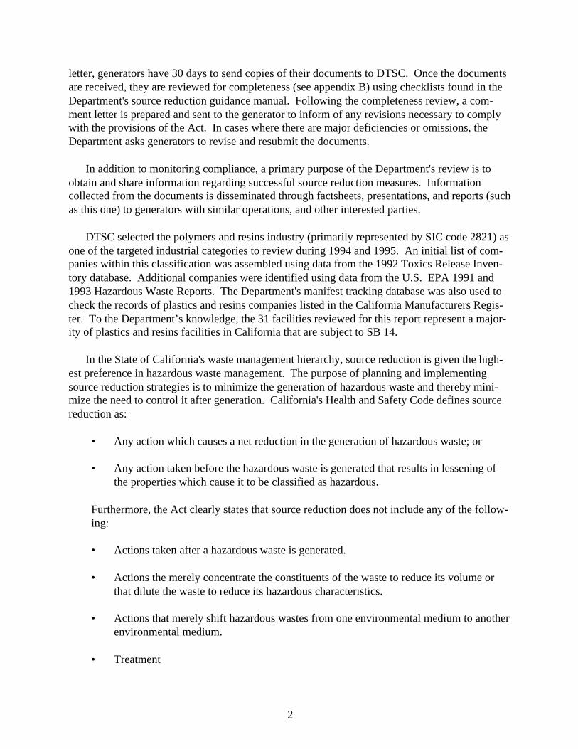
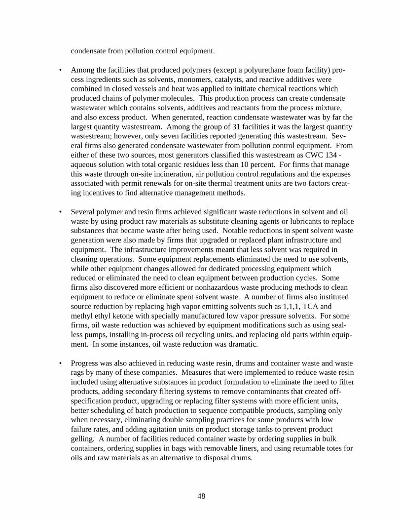
REACTION KETTLE CATALYST MONOMER INPUT CONDENSER INERT GAS HEATING JACKET THINNING TANK DOC. NO. 533 PETE WILSON, GOVERNOR STATE OF CALIFORNIA JAMES M. STROCK, SECRETARY CALIFORNIA ENVIRONMENTAL PROTECTION AGENCY JESSE R. HUFF, DIRECTOR DEPARTMENT OF TOXIC SUBSTANCES CONTROL CALIFORNIA DEPARTMENT OF TOXIC SUBSTANCES CONTROL OFFICE OF POLLUTION PREVENTION AND TECHNOLOGY DEVELOPMENT FEBRUARY 1996 ASSESSMENT OF THE POLYMERS AND RESINS INDUSTRY'S HAZARDOUS WASTE SOURCE REDUCTION PLANNING EFFORTS
Transcript
REACTION KETTLE
CATALYST MONOMER
INPUT
CONDENSER
INERT GAS
HEATINGJACKET
THINNING TANK
DOC. NO. 533
PETE WILSON, GOVERNORSTATE OF CALIFORNIA
JAMES M. STROCK, SECRETARYCALIFORNIA ENVIRONMENTAL PROTECTION AGENCY
JESSE R. HUFF, DIRECTORDEPARTMENT OF TOXIC SUBSTANCES CONTROL
CALIFORNIA DEPARTMENT OFTOXIC SUBSTANCES CONTROL
OFFICE OF POLLUTION PREVENTIONAND TECHNOLOGY DEVELOPMENT
FEBRUARY 1996
ASSESSMENT OF THE POLYMERSAND RESINS INDUSTRY'S
HAZARDOUS WASTE SOURCE REDUCTIONPLANNING EFFORTS
DTSC
State of California Department of Toxic Substances Control Office of Pollution Prevention and Technology Development Contact: Source Reduction Unit Phone: (916) 322-3670
i
ASSESSMENT OF CALIFORNIA POLYMER ANDRESIN MANUFACTURER'S HAZARDOUS WASTE SOURCE REDUCTION
PLANNING EFFORTS
Prepared by David Weightman
State of CaliforniaDepartment of Toxic Substances Control
Office of Pollution Prevention and Technology Development
February 1996
ii
This report was prepared by David Weightman under the direction of Alan Ingham and KimWilhelm, Source Reduction Unit, Office of Pollution Prevention and Technology Development.
Cover by Stan Lau and David Weightman.
ACKNOWLEDGMENTS
The Department sincerely appreciates the efforts of the various facilities in the synthetic andcomposite plastics industry who shared successful source reduction ideas with the Department.A special thank you to all the companies who have worked closely with the Department toprovide information, discuss source reduction issues, or allow the Department to tour their sitesto become more familiar with the processes which produce resins, plastic-reinforced composites,and molded products. The Department would like to specifically acknowledge the cooperationof the following companies:
Paul Fredell, Alpha ResinsBob Doerr, American PolystyreneKen Regopolus, Amoco Foam ProductsH. Reid Mork, Ashland ChemicalJohn Zomer, BASF Corporation (Santa Anna)Dan Donaldson, BP ChemicalsVijay Agarwala, CIBA-GeigyLinda Stover, Courtaulds AerospaceAnthony Pepe and Cef Coles, Cytec Engineered MaterialsGreg Stiglic, Dow Chemical Company (Torrance)Jim Macias and Long Le, Engineering Polymer SolutionsFred Lelvis, Foamex, Ltd.Gregory Thomas and Steve Herron, Georgia Pacific ResinsLarry Palmer, Heller Performance PolymersJoe Karam, Fiber-Resin Corporation (Chatsworth)Randall W. Johnson and Darrel Ong, Hexcel Corporation (Livermore)Neal Lyon, Fiberite Corporation (formerly ICI Composites)Everet Scott Jr. and Joe Ancheta, Keysor Century CorporationDave Kohler and Peter Stamps, McWhorter TechnologiesJeff Mitchell, Mitchell Rubber ProductsChris Madjikian, Neville ChemicalChuck Gibbs, Newport AdhesivesWalt Sharer, Tenneco PackagingLiz Pierce, Polycom HuntsmanEdward Sulick, Reichhold Chemicals (Oxnard)Bradford S. Crawford, Reichhold Chemicals (Azuza)Kimberly Sanderson, Rhone-PoulencMichelle Reynolds, Rohm and Haas (La Mirada)Gene Huber, consultant for Rubber UrethanesCarl Miller and Robert Hoffman, Silmar Resins of Interplastic Co.
iii
DISCLAIMER
The mention of any products, companies, or source reduction technologies, their source ortheir use in connection with material reported herein is not to be construed as either an actual orimplied endorsement of such products, companies or technologies.
iv
v
REPORT OVERVIEW
This report summarizes the results of the Department of Toxic Substances Control's (DTSC)assessment of the polymers and resin industry's source reduction planning efforts, as mandatedby the Hazardous Waste Source Reduction and Management Review Act of 1989 (Act). Theassessment of the polymers and resin industry in California is based upon a review of documentsproduced by a sample of facilities in the state. It includes information on the sources and typesof hazardous waste generated by this industry and describes some of the steps taken to reduce thequantities or hazardous characteristics of waste generated in their operations. In addition, threecase studies are featured as practical examples to show how source reduction practices benefitedparticular facilities.
The Act requires the Department to select at least two categories of generators by StandardIndustrial Classification (SIC) code every two years for evaluation. This evaluation consists ofreviewing documents prepared by facilities which are subject to the Act because of the quantityof hazardous waste generated at their sites. Select facilities were visited to better understand anddescribe their operations and waste management practices. The Act requires hazardous wastegenerators to evaluate options for decreasing the quantity, or the hazardous characteristics, ofhazardous waste routinely generated in their operations.
The polymers and resins production industry, also known as the synthetic plastics industry,was chosen as one of the targeted categories of generators for review of their 1991 source reduc-tion documents prepared under the Act. The primary Standard Industrial Classification (SIC)code represented is 2821 (Plastics materials and resins). To a smaller extent, other SIC codesrepresented in the report include 3087 (Plastics, foam products), and 3086 (Custom compoundpurchased resins).
The three basic manufacturing activities within this industry include polymer production,compounding, and resin processing. This report primarily focuses on companies engaged inpolymer production and compounding. However, five companies whose source reductionplanning documents were reviewed for this report make plastic reinforced composites. Severalof the firms referred to this material as "pre-preg". Pre-preg production involves compoundingor custom blending resins and then impregnating a substrate material such as fiberglass with theresin mixture. The impregnation step in producing plastic reinforced composites is, for thepurpose of this report, considered a processing function. Otherwise, processing generally in-volves using customized resins to form molded or laminated products. While some of the facili-ties assessed for this report process resins, the primary activity of the majority involves produc-tion and/or compounding resins/polymers. Customized or compounded resins generally aremarketed in the following forms: pellets, powders, liquid emulsions, adhesives, or coatings/sealants.
A total of 36 companies were requested to submit their source reduction planning documentsfor evaluation. Thirty-one reviews were completed for this report. Among the 36 companies,two had closed operations, and three were deemed not to be subject to the Act. In addition,responses to the letters requesting that documents be submitted revealed that three of the remain-
vi
ing 31 companies (still operating and subject to the Act) did not complete source reductiondocuments in 1991. These three facilities have since completed documents using 1992 and 1993as baseline years for reporting purposes. In addition to reviewing 31 sets of source reductionplanning documents, DTSC staff visited eight of these facilities.
Although the variation in processes and products within the synthetic plastics industry makesit hard to identify a "largest" wastestream, the Plan review indicated that the most consistentlygenerated wastestream at these facilities was contaminated solvents; in most instances, solventswere contaminated with resin. Liquid solvent-resin waste containing substances such as styrene,acetone, 1,1,1-trichloroethane (1,1,1-TCA), and methylene chloride were generated from activi-ties such as reaction vessel cleaning; excess solvenated resin from treater pans (composite plas-tics manufacturing only); flushing raw material or product transfer pipes or storage tanks; gen-eral equipment and parts cleaning; and, filter screen cleaning.
The identified source reduction measures to reduce solvent-resin waste included findingmore efficient ways clean equipment, adjusting cleaning frequencies, better waste segregation toallow for longer use of solvent solutions, improved batch scheduling to minimize the need toclean and flush product or raw material transfer lines, and in a few cases, equipment redesign andcleaning solution substitution.
Another dominant wastestream was waste resin (in liquid or solid form). This waste wasgenerated because; excess product was made that could not be sold or reused; polymerizationreaction processes were incomplete; contaminated raw materials were used that lead to theproduction of off-specification product; samples could not be reused; product was removed infiltering; and, product was removed when build-up was removed from storage tanks.
Measures reported to reduce this wastestream included altering batch production schedulingto better sequence compatible products, adding dedicated product transfer lines and storagetanks, reworking excess product or samples back into batches, making equipment improvements,better waste segregation, and improving procedures to inspect and store incoming raw materials.
Contaminated or spent oil was another frequently reported waste stream. Typically, the oilwas described as being contaminated with vapors containing water, monomer, solvents, additivesubstances, or some combination of these substances. The sources of waste oil included vacuumpumps, reaction vessel heat transfer coils, and leaks and spills.
Measures taken to reduce this wastestreams included installing sealless pumps, installingpumps using a different sealing fluid, using a different type of oil or other internal lubricant, andimproving equipment maintenance schedules.
Among the companies that produce batch thermoset resins such as alkyds, polyesters, ep-oxies, and phenolics; polymerization reaction process condensate was often reported as thesingle largest quantity wastestream. However, some of the companies that generate thiswastestream did not measure it at the source or report it in their source reduction plans. Whennot reported, generators tended to believe that this by-product from the condensation polymeriza-
vii
tion reaction was not a wastestream for source reduction planning purposes. Some generatorsmistakenly assumed this because the wastewater condensate was inherent to the productionprocess, or because the condensate was treated and discharged to the local POTW under estab-lished parameters for wastewater discharges.
Condensate (the portion which could not be routed back to the reaction vessel for reuse) wasfrequently directed to a separation tank for solvent recovery. The remaining substance, mostlywater, was either treated and discharged to the sewer, or incinerated. In some cases, the conden-sate was captured and reused in later batches of similar or lower grade products. In one case, acompany installed a filter which removed enough impurities to make the water usable in subse-quent batches of similar product. Two companies altered ramp temperature times in order toincrease the efficiency of reaction to reduce reaction condensate waste. One company is in theprocess of installing water treatment/purification equipment that will enable condensate waste-water reuse in boilers and cooling towers (see case study three for details).
A last major wastestream generated by these facilities was bags, drums, and containers whichbecame waste when they were emptied of product. Many companies made significant gains inreducing these wastes. Some companies were able to switch to ordering liquid supplies inreturnable totes rather than disposable drums, other firms worked with suppliers to order suppliesin bulk, and some companies found that they could use liners to prevent bulk bag contamination.Better waste segregation also helped reduce these wastestreams.
In addition to the above wastestream-specific source reduction measures, several companiesimplemented administrative measures such as employee incentive and training programs, wastetracking and logging procedures, and computerized inventory monitoring. Also, three companiesindicated that they had achieved waste reduction via discontinuing or reformulating products.The reformulations included the use of less toxic additives or pigments, or the elimination ofheat-sensitive additives which contributed to the generation of off-specification resinwastestreams.
Section IV of this report provides concise summaries of what various companies in thepolymer/resin industry have done to implement wastestream-specific source reduction measures.Section V presents case studies which describe in detail the costs and benefits associated withimplementing a variety of source reduction measures at three facilities.
In conclusion, information from the submitted documents, and supplemental contacts withfacility personnel, revealed that between 1989-1994, the reviewed facilities identified and imple-mented source reduction measures. Seventy-five percent of the companies achieved reductionsin the amount of hazardous waste manifested from their sites. Total hazardous waste manifestedfrom these facilities decreased by 27 percent when comparing individual baseline data with 1994data.
viii
ix
TABLE OF CONTENTS___________________________________________________________________________
I. Background ..............................................................................................................
II. Introduction .............................................................................................................
III. Overview of Manufacturing Processes ....................................................................
A. Polymer Production ...........................................................................................B. Compounding ....................................................................................................C. Plastic Reinforced Composites ..........................................................................
IV. Wastestreams and Source Reduction Measures ......................................................
A. Liquid Hazardous Wastes ..................................................................................
B. Solid Hazardous Wastes ....................................................................................
1. Waste Polymer and Resin ............................................................................2. Other Organic Solids ...................................................................................
V. Case Studies .............................................................................................................
A. BASF .................................................................................................................B. Tenneco Packaging Corporation ........................................................................C. McWhorter Technologies ..................................................................................
VI. Summary ..................................................................................................................
A. Sample SB 14 Document Call In Letter ............................................................
B. SB 14 Plan Completeness Checklist ..................................................................
1
5
11
111213
15
20
202527
28
2931
33
333841
47
53
53
55
x
1
I. BACKGROUND
The Hazardous Waste Source Reduction and Management Review Act of 1989 (SB 14)applies to businesses that generated over 12,000 kilograms (13.2 tons) of hazardous waste, or 12kilograms of extremely hazardous waste, in 1990. The law requires generators to prepare docu-ments which reflect their efforts to identify, and then implement feasible methods for reducingthe quantity and/or the hazardous characteristics of hazardous waste routinely generated in theiroperations. The first set of source reduction documents was due September 1, 1991. Documentsare to be completed every fours years thereafter, provided that the above threshold is exceeded inthe "reporting year". The reporting year is the year which immediately precedes the year inwhich the documents are required to be completed. For example, the most recent SB 14 docu-ments should have been completed by September 1, 1995, for wastes generated in 1994 (themost recent reporting year)
To comply with the Act, generators must prepare a Source Reduction Plan (Plan), a Manage-ment Performance Report, summaries of the Plan and the Report, and a Progress Report. ThePlan must include information about the facility's operations and provide waste generation datafor the reporting year. The Plan must also include a list of potential source reduction alternativesfor "major" wastestreams that are routinely generated, and describe the company's evaluation ofthe alternatives. Major wastestreams are those that exceed five percent of the total weight ofroutinely-generated hazardous wastes.
Using specific criteria to evaluate a source reduction measure's feasibility, such as amount ofreduction, technical feasibility, economic viability, and effect on workplace health and safety;the Plan must describe the rationale for choosing or rejecting measures for implementation. Thegenerator must then specify a timetable for implementing feasible source reduction options.Finally, the Plan must contain technical and financial certifications to ensure that the documentswere prepared with the oversight of those responsible for day-to-day operations, and an owner oroperator who has the authority to commit financial resources necessary to implement the Plan.
The Management Performance Report (Report) discusses wastestream generation and man-agement, and describes source reduction measures and other changes in waste managementpractices that have been made since the baseline year. As with the Plan, the Report must alsocontain technical and financial certification statements.
The purpose of the Progress Report is to track, on a biennial basis, the percentage of wastereduction achieved for the site's major wastestreams, normalized to account for changes inthroughput (or other relevant factor(s)). Companies subject to SB 14 satisfy the Progress Reportrequirement by using Form GM from their U.S. Environmental Protection Agency BiennialHazardous Waste Report.
The Act requires the Department of Toxic Substance Control (DTSC) to select at least twocategories of generators by Standard Industrial Classification (SIC) code every two years andrequest that selected generators submit documents for review. The review process involvessending request letters to generators via certified mail (see appendix A). Upon receipt of the
2
letter, generators have 30 days to send copies of their documents to DTSC. Once the documentsare received, they are reviewed for completeness (see appendix B) using checklists found in theDepartment's source reduction guidance manual. Following the completeness review, a com-ment letter is prepared and sent to the generator to inform of any revisions necessary to complywith the provisions of the Act. In cases where there are major deficiencies or omissions, theDepartment asks generators to revise and resubmit the documents.
In addition to monitoring compliance, a primary purpose of the Department's review is toobtain and share information regarding successful source reduction measures. Informationcollected from the documents is disseminated through factsheets, presentations, and reports (suchas this one) to generators with similar operations, and other interested parties.
DTSC selected the polymers and resins industry (primarily represented by SIC code 2821) asone of the targeted industrial categories to review during 1994 and 1995. An initial list of com-panies within this classification was assembled using data from the 1992 Toxics Release Inven-tory database. Additional companies were identified using data from the U.S. EPA 1991 and1993 Hazardous Waste Reports. The Department's manifest tracking database was also used tocheck the records of plastics and resins companies listed in the California Manufacturers Regis-ter. To the Department’s knowledge, the 31 facilities reviewed for this report represent a major-ity of plastics and resins facilities in California that are subject to SB 14.
In the State of California's waste management hierarchy, source reduction is given the high-est preference in hazardous waste management. The purpose of planning and implementingsource reduction strategies is to minimize the generation of hazardous waste and thereby mini-mize the need to control it after generation. California's Health and Safety Code defines sourcereduction as:
• Any action which causes a net reduction in the generation of hazardous waste; or
• Any action taken before the hazardous waste is generated that results in lessening ofthe properties which cause it to be classified as hazardous.
Furthermore, the Act clearly states that source reduction does not include any of the follow-ing:
• Actions taken after a hazardous waste is generated.
• Actions the merely concentrate the constituents of the waste to reduce its volume orthat dilute the waste to reduce its hazardous characteristics.
• Actions that merely shift hazardous wastes from one environmental medium to anotherenvironmental medium.
• Treatment
3
The primary purpose of this report is to provide information regarding hazardous wastesource reduction activities implemented by polymers and resins industry facilities. Therefore,discussion of reuse or recycling practices is very limited.
4
5
II. INTRODUCTION
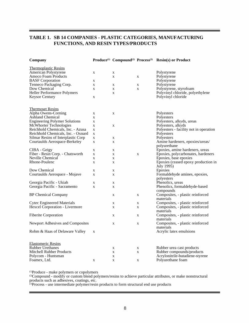
This report examines the hazardous waste source reduction practices of California polymersand resins manufacturing firms. The facilities assessed for this report, listed on Table 1 on page8, are grouped by the primary polymers and resins categories that they formulate, and the end useor intermediate products which they market. In the broader picture, polymers and resins (alsoknown as "synthetic plastics") is a subset of the chemical manufacturing industry. This subset isdirectly linked with three upstream industries: raw material extraction, raw material refining andindustrial organic chemical production. The raw materials used to make polymers and resins,i.e., monomers and chemical additives, originate from the distillation of energy resources includ-ing natural gas, coal and petroleum. Manufacturing sectors within the industry include polymerformation (production), resin compounding, and plastics/resins processing. Processing, not thefocus of this report, generally involves using resin pellets, sheets, reinforced composites andother intermediate polymer products to form end use products using specific processing methods.Diagram 1 illustrates the progression from basic petrochemicals to finished plastic products.
DIAGRAM 1. PROGRESSION FROM BASIC PETROCHEMICALS TO FINISHEDPLASTIC PRODUCTS
ADHESIVESCOATINGSSEALANTSEMULSIONS
PLASTICREINFORCEDCOMPOSITES
INDUSTRIALORGANICCHEMICALS
PETROCHEMICALS COMPOUNDINGPOLYMER/RESINPRODUCTION
MOLDED ORFABRICATEDPRODUCTS
Adopted and modified from "Industrial Process Profiles for Environmental Use: Chapter 10A- Plastics andResins Processing Industry." Radian Corporation. July 1985. McLean, VA.
Polymer production (formation) involves forming long chains of molecules by using specificraw materials with specific polymerization reaction methods. Typically, polymerization beginswith an exothermic reaction initiated with heat and catalysts. Process variables such as time,temperature, and pressure are carefully controlled. (more detailed description of production
6
(formulation) and compounding is provided in the following section).
Compounding involves modifying a polymer/resin to provide the final product with attributessuitable for a particular use. This manufacturing phase can occur just before or during theprocessing operation, or partially during production (formulation) and partially during process-ing. It includes steps such as adding pigments for color, adding fillers to increase strength orlower cost, adding plasticizers (which act as lubricants), adding hardening agents that controlcuring rates, or adding other agents to obtain characteristics such as flexibility, opacity, impactstrength, adhesiveness, or fire resistance, among many other possible characteristics.
The production (formation) and compounding methods used to make polymers/resins arefunctions of the form in which the plastic substance is needed. For example, resins can beproduced in a liquid form for use as an adhesive, or formulated for use in spray coatings, lac-quers and varnishes, and paints. The same resin type can be formed as a powder to be used tomake a molded or casted product.
Polymers/resins produced by the synthetic plastics industry fall into one of three primarycategories: thermosets, thermoplastics, or elastomers (or elastomeric thermoplastics). Thermosetresins undergo chemical change during polymerization. In a fully cured, or fully polymerizedstate, thermoset molecules are cross-linked. This means that the molecules are permanentlyinsoluble and infusible. Prior to reaching this state they are typically produced as intermediateproducts (which represent a stage of polymerization). These intermediate products are some-times referred to as A-stage, or B-stage resins. These terms indicate a degree of chemical/molecular bonding in the substance, which affects how the polymer/resin can be modified. Ingeneral, A-stage resin is soluble and fusible (meltable), while the B-stage resin is insoluble andonly partially fusible. Some examples of thermosets include unsaturated polyesters, epoxies,phenolics, and rigid urethane resins.
Unlike thermosets, thermoplastic resin molecules are unlinked. In their cured state thermo-plastics can be softened by heating or hardened by cooling. Because of this characteristic, pre-or post-consumer recycling is possible. Aside from being meltable, most thermoplastics resinsare soluble in specific solvents. Some types of thermoplastic resins include: polyvinylchloride,polystyrene, acrylics, and polyamides. These resins are frequently used to make consumerproduct packaging.
The third broad category of synthetic resins is elastomers, sometimes referred to as elasto-meric thermoplastics. As implied in the name, elastomers are elastic in their cured state. Theystretch and compress to varying degrees at ambient temperatures depending upon the amount ofstress (force) applied. Examples of elastomers include synthetic rubbers, chlorinated polyethyl-ene, acrylonitrile-styrene-butadiene, and acrylates. A common example of an elastomer productis polyurethane foam, a material used in furniture cushions and bedding materials.
The largest group of facilities reviewed for this report produce intermediate thermosetting(non-fusible and non-soluble) resins, in powder form, liquid form, or as adhesives. Sourcereduction documents were also reviewed for companies that polymerize and extrude thermoplas-
7
tic resins used in molded products, facilities that make reinforced composites used in laminatedmaterials, and two facilities exclusively engaged in compounding resins. Lastly, documentswere reviewed for two manufacturers of rubberized products and for one facility that manufac-tures polyurethane foam.
Distinctions between groups of facilities based on the primary resin/polymer categories(described in subsequent paragraphs) are important. Different types and quantities of hazardouswaste are generated among polymer/plastic manufacturers depending upon products made.Somesource reduction measures have potential application in a broad range of polymer/resin manufac-turing facilities. Other measures may only apply to facilities making certain categories of plas-tics because of distinct processes and wastestreams.
For example, thermoset polymers, when compared to thermoplastic polymers, are extremelyspecific in their constituents and form; like recipes designed to please an individual's palate.Because of this, thermosets are more limited than thermoplastics in possible input substitutionsrelated to product formulation. In addition, thermoset polymers often generate reaction processwastewater. This wastewater starts as a condensate which forms when vapor exhaust from thepolymerization reaction cools to a liquid. Thermosets are also usually produced on a batch-by-batch basis. With thermoplastic polymers, reaction process wastewater is typically not gener-ated. Instead of becoming wastewater, the condensate is returned to the reaction vessel duringthe polymerization reaction. In addition, thermoplastics are usually made in a continuous pro-duction process.
The batch production process common to thermosets can complicate attempts to correlatewaste generation with production throughput. Batch sizes can range from a few hundred poundsto hundreds of tons. Equipment cleaning, which often generates liquid solvent-resin waste, maybe necessary between batches regardless of batch sizes and total facility production. In addition,producing a large number of products (characteristic of batch production operations) affects theamount of excess (waste) product generated which also may not be related to total productionthroughput.
Table 1, organized by plastics category, lists the companies reviewed for this report, eachcompany's primary manufacturing activities, and the polymer or primary resins/products made ateach facility. The SIC code which represents most of the companies included in this report is2821 (plastics materials and resins). Facilities were identified from information contained in the1992 Toxics Release Inventory database, and from waste quantity information in theDepartment's 1990 manifest records.
There are literally thousands of intermediate and end-use products produced from the threetypes of polymer categories described above. These products affect a broad range of industries.The expansion of polymers and resins production into these industries, is due to several factors:increased use of plastics as a substitute material for glass and metal products, development ofnew products, and increased sophistication in plastics processing methods and polymerchemistry.Some of the primary industries affected by the expanded use of polymers includeelectronics, aerospace, textiles, furniture, household products, automobiles, and the packaging
Company Produce(1) Compound(2) Process(3) Resin(s) or Product
Thermoplastic ResinsAmerican Polystyrene x x PolystyreneAmoco Foam Products x x PolystyreneBASF Corporation x PolystyreneTenneco Packaging Corp. x x x PolystyreneDow Chemical x x x Polystyrene, styrofoamHeller Performance Polymers x Polyvinyl chloride, polyethyleneKeysor Century x Polyvinyl chloride
Thermoset ResinsAlpha Owens-Corning x x PolyestersAshland Chemical x PolyestersEngineering Polymer Solutions x Polyesters, alkyds, ureasMcWhorter Technologies x x Polyesters, alkydsReichhold Chemicals, Inc. - Azusa x Polyesters - facility not in operationReichhold Chemicals, Inc. - Oxnard x PolyestersSilmar Resins of Interplastic Corp x x PolyestersCourtaulds Aerospace-Berkeley x x Amine hardeners, epoxies/ureas/
polyurethaneCIBA - Geigy x x Epoxies, amine hardeners, ureasFiber - Resin Corp. - Chatsworth x x x Epoxies, polycarbonates, hardenersNeville Chemical x x Epoxies, base epoxiesRhone-Poulenc x x Epoxies (ceased epoxy production in
July 1995)Dow Chemical x x EpoxiesCourtaulds Aerospace - Mojave x x Formaldehyde amines, epoxies,
polyestersGeorgia Pacific - Ukiah x x Phenolics, ureasGeorgia Pacific - Sacramento x x Phenolics, formaldehyde-based
compoundsBP Chemical Company x x Composites, - plastic reinforced
materialsCytec Engineered Materials x x Composites, - plastic reinforcedHexcel Corporation - Livermore x x Composites, - plastic reinforced
materialsFiberite Corporation x x Composites, - plastic reinforced
materialsNewport Adhesives and Composites x x Composites, - plastic reinforced
materialsRohm & Haas of Delaware Valley x Acrylic latex emulsions
Elastomeric ResinsRubber Urethanes x x Rubber urea cast productsMitchell Rubber Products x x Rubber compounds/productsPolycom - Huntsman x Acrylonitrile-butadiene-styreneFoamex, Ltd. x x x Polyurethane foam
(1)Produce - make polymers or copolymers(2)Compound - modify or custom blend polymers/resins to achieve particular attributes, or make nonstructuralproducts such as adhesives, coatings, etc.(3)Process - use intermediate polymer/resin products to form structural end use products
9
industry.
Because polymers are used in such a wide variety of industries, changes in the economy cannoticeably affect production output in the polymers and resins industry. The economic recessionof 1991-1993 is a case in point. A number of polymer/resin firms decreased production becauseof depressed market demand during the recession. Other polymer manufacturers were affectedby downsizing occurring in the aerospace industry due to decreased orders associated withreduced national military spending. Some of the firms assessed for this report relied heavily onaerospace companies as markets for their products. Because of the economic recession, theaerospace industry decline, and other factors, between 1990 and 1994 some polymer/resin firmswent out of business or consolidated, while others increased production due to reduced competi-tion in the market.
Among the 36 firms included in the initial SB 14 review, three ceased operations and anotheris planning a shutdown of one of its facilities. Other firms assessed for this report were boughtby other companies, and some changed product lines. Several firms also noted that they hadreceived products and materials from other facilities in the U.S. that had closed; some of theseproducts and materials had to be disposed as hazardous waste.
It has not been possible, based upon the information provided in the source reduction docu-ments, to determine an overall percentage decrease in waste generation that reflects industry-wide progress due to source reduction practices. Most of the documents did not normalize wastegeneration data to account for production throughput changes or other factors, such as receivingwaste from other facilities, when estimating waste reduction due to source reduction. However,it appears that most facilities instituted source reduction measures. Manifest data shows a 27percent reduction in waste shipped off-site by these facilities between 1990 and 1994. In futureplanning efforts by this industry, more effort should be made by individual facilities to normalizewaste reduction figures/percentages. Data normalization should account for relevant factors thatimpact waste generation (other than source reduction) and allow for an accurate assessment ofwaste generation decrease due to implementing source reduction measures.
10
11
III. OVERVIEW OF MANUFACTURING PROCESSES
This section provides a general description of processes that are used by the synthetic plasticsmanufacturing industry to make polymers (condensation and addition polymerization), modifypolymers (compounding), and to make plastic reinforced composites. The methods describedbelow, in actual practice, contain many variations. These descriptions represent information thathas been provided in SB 14 source reduction planning documents, and gathered from conversa-tions with facility personnel. In plastics manufacturing (and also processing), there are manycases in which production process details/methods are unique to a facility or company and areconsidered proprietary because these methods may provide competitive market advantage. Inthe final analysis, the polymerization and/or compounding methods used by a facility are func-tions of the form of the polymer/resin, the quantities made, and the chemistry of the polymercompound's raw materials.
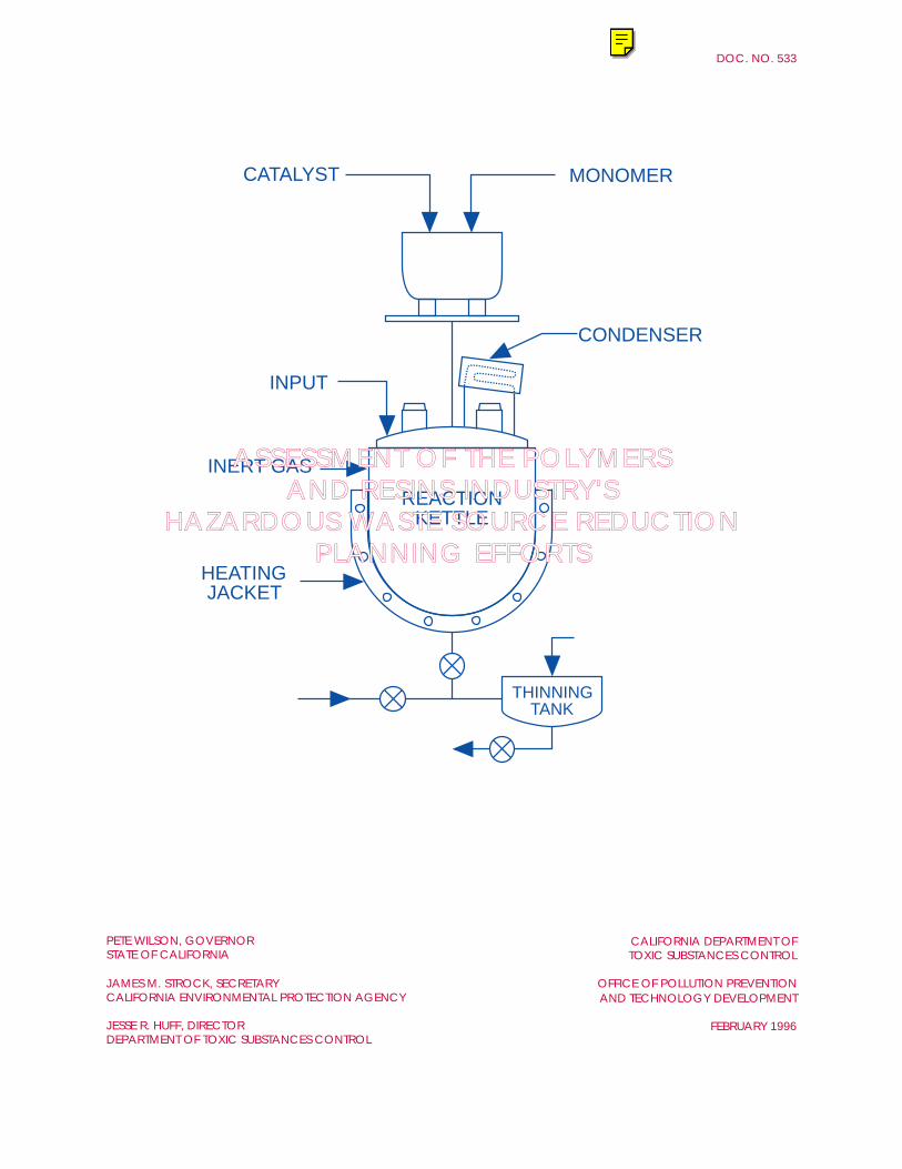
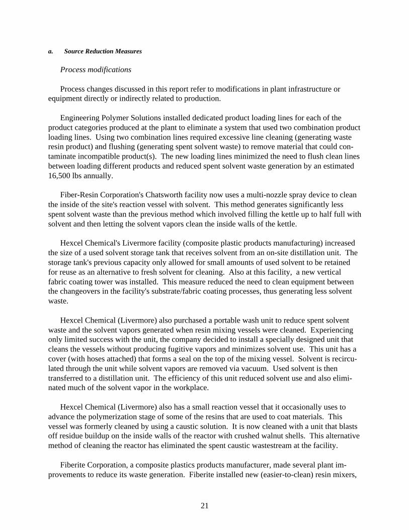
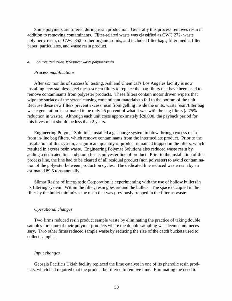
The general process used to produce polymers, or co-polymers (polymers compounds madewith more than one monomer) starts when specific chemicals, monomers, catalyst, additives and/or solvents are charged into a reaction vessel, sometimes referred to as a "kettle". The mixture isthen heated using a heat transfer fluid, such as oil or water, that is contained within a jacket ofcoils inside or outside the kettle. Typically, excess air is removed from the vessel by vacuumand excluded during the reaction by using a pressurized gas such as nitrogen. As the substancesin the vessel react, long chains of molecules called "polymers" are formed. This process is calledpolymerization.
A. POLYMER PRODUCTION
Thermosets. Facilities that produce/formulate thermoset polymers typically describe theinitial reaction phase as "condensation" polymerization. During the reaction, a condensate isformed when unreacted and partially reacted monomers and additives, in combination with watermolecules released in the reaction, vaporize, cool, and then collect in a condenser or series ofcondensers. This condensate, if not recycled in the process, becomes a wastewater by-product.Thermoset polymers are typically produced on a batch-by-batch basis and the product developedin the reactor is usually not fully polymerized ("cured"). As discussed earlier, the partially curedcondition of the process stream allows the substance to be modified, subject to its specific chemi-cal makeup and polymerization stage. Once removed from the reaction vessel(s), this processstream may undergo viscosity adjustment; usually, this means the mixture is diluted with solvent.The mixture may also be filtered to remove contaminants.
Thermoplastics and Elastomers. Although not all products are produced using reactionvessels, (polyurethane foam is an example) facilities that formulate thermoplastics and elas-tomers typically describe the reaction phase as "addition" polymerization. Generally, additionpolymerization involves one type of monomer species and is begun by using an initiator whichactivates monomers by breaking a double bond between atoms. The reaction phase is often acontinuous process that may take place in a series of reactors. As with thermoset polymerizationreactions, chemical reactions between the process ingredients in the vessel do not reach 100%
12
efficiency. As a result, some additives and reactant substances, combined with water, passthrough (are vacuumed off) the reaction process partially altered or unaltered, as vapor. How-ever, unlike thermoset reactions, the vapor does not usually become wastewater once it has beencondensed and collected. Condensed vapor from the reaction is either reused directly in thereaction, or is collected and used as a makeup ingredient for later batches. Partially-reactedparticles remaining in the process stream may generate waste when the product is filtered.
In some polymerization reactions, chemically complex reactants and additives in the poly-merization vessel undergo side reactions which create low molecular weight polymer. This off-specification polymer is sometimes referred to as "dimers" or "trimers", depending on the num-ber of molecules in the polymer chain. This low weight polymer, including any unreacted andpartially-reacted process additives drained from the vessel, generates waste. Although a portionof the reject low weight polymer may be reusable within the product batch, the unusable portioncan sometimes constitute a significant wastestream.
It is important to note that addition or condensation reaction polymers can be produced viaseveral methods. These polymerization methods include solution, mass, suspension, and emul-sion, or some combination of these. To a large extent, the polymerization method used to pro-duce a polymer is a function of the form of the final or intermediate product. However, forpurposes of this report, it is more important to note that process variables in polymerizationreactions can affect the amounts or toxicity levels of waste generated. Some of the key polymer-ization reaction variables include heating ramp times for process mixtures, peak temperatures,cooking (reaction) time, the degree to which vacuum and agitation is applied to the processstream, catalyst(s) pH level, and the rate at which catalyst is added to the mixture.
B. COMPOUNDING
In a majority of instances, the polymer formed in the reaction is modified to fabricate aparticular product, or to suit the needs of a customer who will use the product for a very specificapplication. As mentioned earlier, compounding is often a multi-step operation that can occurpartially or wholly once the resin has reached a particular stage of the polymerization. Com-pounding may occur at the production facility, or it may occur as a completely separate operationat a different facility. Polymer compound modification may also be a staged process startedduring the manufacture of the polymer and completed as the polymer is used in a resin process-ing operation.
Polymer compounds can be modified in many ways and the methods and equipment avail-able for this purpose are quite varied. Some common ways to modify polymers involve addingfillers to increase strength and lower costs, adding plasticizers to facilitate use of the intermediateproduct in processing operations such as molding or casting, adding pigments for color, addingfire retardants to achieve ignition resistance, and adding stabilizers to prevent degradation due toexposure to chemicals, light or moisture.
13
A typical compounding operation starts by mixing proportions of polymer and additives inmixing vessels, blenders, or hoppers.In the mixing vessels, the polymer, in dry, paste or liquidform, is pre-blended with additives until the polymer and additives obtain a homogeneous mix.In some instances, blending occurs in several stages. The particular blending technique(s) used(as reflected by the equipment involved) may depend upon the polymer being modified andformulation additives being used. After the initial blending, some mixtures are then filtered.Resin mixtures then undergo fusion as a result of the application of heat and/or shearing action,during which other additives may be incorporated into the polymer's matrix. With thermosetresins heat and shearing action must be carefully controlled to prevent premature curing. Afterthe mixtures' ingredients are incorporated and homogeneously dispersed, the mix is then shapeddepending upon how it will be used in processing operations. Typically this involves discharg-ing the polymer to pelletizers, dryers, or processing equipment. The final shape generally takesthe form of sheets, granules, pellets, or powder, depending upon the application.
Thermoset compounds, in an uncured state, either A-stage, or B-stage, are frequently used toform paints, sealants and coatings, adhesives, or molding powders. Thermoplastic resins areoften extruded as sheets, rods, or pellets. Pellets are typically remelted as feedstock for injection,thermoforming, or blow mold processes.
C. PLASTIC REINFORCED COMPOSITES
Pre-preg, is a plastic resin reinforced material which is a primary product made at five facili-ties reviewed for this report. Pre-preg is an intermediate product sold as rolls of resin-impreg-nated material. The resin in the material is only partially cured (B-stage); therefore, the materialis flexible. The material to be impregnated with resin is purchased by the pre-preg manufactur-ing facility in the form of a woven sheet/cloth or mat, or unidirectional fiber, wound on rolls.This material is called the "substrate". The substrate is commonly made out of substances suchas glass, graphite, or Kevlar®. After the substrate material is pre-impregnated with resin, it istypically cut to specific widths and stored in cool conditions to prevent the resin from furthercuring. This intermediate product is then used by fabricators (e.g., laminators) who shape thematerial and complete the curing stage of the resin. Although both thermosets and thermoplasticresins can be used to make composites, thermosets such as alkyds, polyesters, epoxies, andphenolics were the resins most commonly reported.
There are two dominant processes used in pre-preg production described in the SB 14 docu-ments: solvent-based, and hot-melt coating. In both processes, thermoset resins, which arepurchased in A-stage form (partly soluble, partly fusible), are first mixed with a solvent(grosser), an activator, pigments, fillers, and other additives. The mixing vessels used for thisoperation range from small to large sizes, depending on the batch. The mixing process continuesuntil a specific viscosity and mix uniformity is reached. This may take several hours to com-plete. If the mixture is not used promptly, it is placed in cold storage to prevent further curing.
Solvent based impregnation. There are two variations of the "solvent-based" impregnationprocess; one in which the resin is pumped to a "treater" or dip pan within a vertical tower, and
14
another in which strands of fiber are meshed onto a roll coated with resin adhesive.
In the tower, resin in the treater pan at the bottom of the unit is dissolved in solvent. Areservoir, sometimes called the "bean pot" feeds solvent to the treater pan to precisely adjust thespecific gravity of the resin coating mixture. As the substrate (sheet) is unwound from its roll ata given speed, it is diped into a resin mixture within the treater pan. This dipping may occurmultiple times. A second dip pan may be used, depending upon the product being made. Eachtime the sheet is dipped in the resin solvent mixture, it is run through rollers (set at a specificgap), which mesh the resin mix into the sheet. Then the impregnated sheet passes through one ormore oven drying zones. Oven drying cures the material to a B-stage (insoluble and partiallyfusible) condition. Solvent vapors that are emitted during the oven drying process are exhaustedto a thermal incinerator, or they may be condensed in a air cooling chiller. The resin -impreg-nated material is then cut to size and wound onto rolls. As noted, this process converts A-stageresin to the B-stage (insoluble and partially fusible).
In a variation of the solvent-based impregnation process, strands of fiber are unwound from acreel and fed into a machine that meshes the fiber into a resin adhesive coated roll. Solvent fromthe coated roll soaks into the fibers as the fibers mesh with the roll. Simultaneously, releasepaper is applied to the two sides of the impregnated sheet, which is then wound into rolls.
Hot melt impregnation. Hot melt impregnation uses heat to control the viscosity of the resinmix used to impregnate the substrate in lieu of solvents. In the hot-melt coating method, rolls ofsubstrate are fed as a continuous web to a machine that contains a dam filled with resin. Thisparticular machine's line speed, roll gaps, temperature settings, and the resin mixture's specificgravity are controlled by a line operator. The sheets are impregnated when the rollers mesh resininto the fabric sheet, while release paper is added to one side of the roll so that it may later beunwound.
15
IV. WASTESTREAMS AND SOURCE REDUCTION MEASURES
This section contains a discussion of the types, quantities, and sources of hazardous wastesgenerated by the 31 facilities assessed for this report. Source reduction measures that wereimplemented to reduce waste quantity or toxic characteristics are also summarized. Althoughsome of the source reduction measure descriptions include quantitative data, more detailedinformation regarding waste generating processes, implementation costs, cost savings, and wastereduction quantities is presented in Section Five. Section Five presents case studies whichdescribe in detail the background, the costs, and the benefits associated with implementing avariety of source reduction measures at three facilities.
The most typical source reduction measures cited in the reviewed documents involvedmaking raw material substitutions, or changing the methods, used to accomplish production andoperations related tasks. To a lesser extent, some facilities reduced waste by upgrading equip-ment (making capital improvements), and a number of firms briefly discussed making adminis-trative changes. In many instances, the critical information relating to the criteria used to decidewhat measures to implement was only generally discussed, or was not documented in the Plans.These Plans would have more value to the Department for technology transfer purposes had thisinformation been included. For the facilities, including information such as implementationcosts, waste reduction quantity estimates, and economic benefits in the documents provides awritten record with baseline information. Baseline information can be used to determine theaccuracy of assumptions and monitor progress towards reaching future waste reduction targets orgoals.
Polymer production, modification and processing operations generate pollution from hazard-ous and nonhazardous liquid wastes (which include wastewater), solid wastes, and air emissions.The sources and types of waste from any one facility generally depend upon the type and form ofpolymer(s) made at the facility and scope of production, modification, and processing activity atthe site. Polymer form (liquid, solid powder, pellets, etc.) is a function of the type of polymer-ization reaction (addition or condensation) and the polymerization method(s) used to produce thepolymer. There are four types of polymerization methods used in the industry. These methodsinclude mass, solution, suspension, and emulsion polymerization (either separately or in combi-nation). These methods vary in the ways in which process ingredients are added to the reactionvessel (reactor), and the extent to which water and/or solvents are used as ingredients in thereaction vessel.
The different polymerization methods create both hazardous and nonhazardous wastes ofvarying types, concentrations, and characteristics. For example, solution and mass polymeriza-tion methods involve using solvents in the polymerization reaction mixture. Vapor vented fromthe reaction, which is condensed to a liquid, typically contains solvent and partially-reacted andunreacted process substances. The portion of this liquid condensate that is not recycled in theprocess becomes a generated wastewater. If it is economically justifiable, some facilities willrecover solvent from this wastewater by using separation tanks and/or distillation units. Theseunits generate secondary wastestreams such as solvent sludge and activated carbon filters.
16
In mass polymerization processes, the conversion level of monomer(s) to polymer/copolymeris typically lower than with solution, suspension, and emulsion methods. As a result, greateramounts of low molecular weight polymer may result. If not recycled in the process, these low-weight polymers may become off-specification waste. In suspension polymerization, water ischarged to the reactor vessel to disperse monomer and transfer heat to the mix, which increasesthe rate of chemical reactions. Once the conversion level of the process mix is reached, andfollowing the discharge and cooling of the process stream, the beads of polymer are typicallydewatered and then dried. Dewatering generally produces a nonhazardous wastewater. Afterdewatering, the polymer may be dried in ovens or in a centrifuge. Vents from the ovens orcentrifuge may be sources of particulate waste and/or volatile organic compounds.
Figure 1 compares the eight largest manifested waste categories generated in 1990 with themanifested amounts of the same waste categories in 1994 (by the 31 facilities). The largestquantity waste type category , California Waste Code (CWC) 134 - aqueous solution with totalorganic residues < 10 percent, is not shown on the chart because only a small quantity of thiswaste type was manifested. Most waste categorized as CWC 134 was managed by on-sitetreatment and then discharge to a Publicly Owned Treatment Works (POTW). In addition, themajority of waste classified as CWC 134 was generated by two facilities.
Figure 1 indicates that solvents or solvent-containing wastes were the largest quantity mani-fested wastes generated by these 31 sites as a group during 1990. In the SB 14 documentssolvent wastestreams were reported under CWCs 211, 212, 213, and 214. However, the largestquantity of solvent wastes were reported under CWC 214 - unspecified solvent mixture (22.7%,by weight, of the eight largest manifested wastestreams) and CWC 212 - oxygenated solvents(15.4% by weight of the largest eight manifested wastestreams). Twenty of the 31 firms reportedsolvent-containing wastes during the baseline year.
CWC 134, not shown on Figure 1, represents by far, the largest quantity waste type category,(approximately 86,000 tons versus the second largest wastestream by waste code CWC 214 -1,375 tons) generated by these 31 firms in 1990. However, this waste type was reported by onlyseven companies in 1990. Two of the seven companies generated 93 percent of the total pro-duced by the seven facilities. A few of the companies that generated wastewater failed to reportit in their SB 14 Plans. Therefore the weight quantity of this waste type is probably higher thanthe data indicates.
The remaining six largest quantity wastestreams manifested by this group of facilities (1990)in descending order of total quantity and percentage among the eight largest manifestedwastestreams were: CWC 352 - other organic solids (12.3%), typically used to classify wasteresin, bags, filter media, and carbon from water or air emissions control units; CWC 271 - or-ganic monomer waste (12.1%), which included unreacted or partially reacted process streamscontaining monomer; CWC 512/513 - empty containers (11.9%), represent empty drums, bags ornylon supersacks of various sizes; CWC 272 - waste resin (11.1%); CWC 133 - aqueous solutionwith total organic residues 10% or more (8.9%) and, CWC 221, 222, and 223 which includedwaste oil and oil sludge (5.6%). The relative percentages of each of the eight largest manifestedwaste type categories during 1990 are shown on Figure 2.
17
OIL AND
OIL SLUDGE
AQUEOUS
SOLUTION
W/ > 10%ORGANICS
1,600
1,400
1,200
1,000
800
600
400
200
0
TO
NS
OF
HA
ZA
RD
OU
S W
AS
TE
OXYGENATED
SOLVENTS
UNSPECIFIED
SOLVENT
MIXTURE
ORGANIC
MONOMER
WASTEEMPTY
CONTAINERS
POLYMERIC
RESIN
WASTE1
221-223133272512/513271352212214
TONS 90
TONS 94
CALIFORNIA WASTE CODE
FIGURE 1. PLASTICS AND RESINS FACILITIES: LARGEST MANIFESTED WASTESTREAMSWASTE GENERATION BY WASTE CODE, 1990 & 1994
OTHER
ORGANIC
SOLIDS
1 INCREASE DUE TO ONE FIRM THAT MANIFESTED A LARGE AMOUNT OF CWC 272 IN 1994 THAT WAS MANAGED ON SITE IN1990
18
FIGURE 2. LARGEST MANIFESTED WASTESTREAM CATEGORIES BYPERCENTAGE (1990)
CWC = CALIFORNIA WASTE CODE
CWC 214UNSPECIFIED SOLVENT
MIXTURE
CWC 212OXYGENATED SOLVENTS
CWC 221-223OIL/SLUDGE & UNSPECIFIED OIL WASTE
CWC 133AQUEOUS SOLUTION
<10% ORGANICS
CWC 271ORGANIC MONOMER
WASTECWC 352
OTHER ORGANIC SOLIDS
CWC 512/513CONTAINERS
CWC 272POLYMERIC RESIN
WASTE
12.3%
15.4%
22.7%
12.1%
11.9%
11.1%
8.9%5.6%
In a number of instances, 1990 DTSC manifest data differed from the data reported in the SB14 Plans. This included differences in waste quantity and waste code types. When significantdifferences were encountered, facility personnel were contacted and asked to review facilityrecords. Changes were made to the data presented on Figure 1, when appropriate, on the basis ofadditional or updated information supplied by facility personnel.
The remainder of this section discusses waste sources and source reduction measures withinthe two major categories of generated wastes: liquid hazardous wastes and solid hazardouswastes. Within these categories, polymer and resin manufacturing industry waste types andsources are addressed. Table Two summarizes this information. Following the discussion ofeach wastestream type and its source(s), source reduction approaches that were implemented orevaluated by particular companies (reviewed for this report) are briefly described. Each sourcereduction measure description is grouped under one of five categories; input substitutions,process modifications, operational changes, product reformulations, and administrative changes.As previously mentioned, detailed discussions regarding wastestreams, and implemented source
19
Hazardous Waste Categories and Types Primary Sources of Generation & Source ReductionMeasures Page Number Citations
LiquidsCondensate wastewater containing solvents Polymerization reactions, air/vapor pollution control equip-
ment, settling tanks (25, 26, and 27)
Spent solvent Cleaning plant infrastructure and equipment (22, 23, and 24)
tion polymer, excess or obsolete product, (32, 33)
filtered product, transfer line drainings; using contaminatedraw materials, quality control / laboratory sampling wastes
Filter media Filtering: includes paper, screens, grit etc. (32)
Bags/containers/drums Emptying raw material and supply containers/bags etc. (32,33)
Dust/particulates Drying, flaking, transferring, and bagging polymer
Absorbent/rags Cleanup of spills and leaks
Waste catalyst and waste additives Polymerization reaction, expired shelf life materials, materialspills. Loading and unloading materials.
Spent carbon Air and water filters
Scrap material Resin impregnated materials roll cuttings
Asbestos Insulating material on pipes and vessels
Laboratory materials Crushed glass, containers, various excess chemicals andmiscellaneous trash
Air Emissions(1)
Volatile organic compounds Equipment vents, vessel openings, valves, seals, tank vents,resin mixtures or slurries, distillation columns
Dust/ particulates Polymer drying and bagging operations, loading and unload-ing materials
(1) Although outside the scope of this report, air emissions can be significant sources of pollution at polymer/resinfacilities. As such, they are included in this table.
TABLE 2. TYPES AND SOURCES OF WASTE AND EMISSIONS AT POLYMERFACILITIES
20
reduction measures for specific facilities, are presented in three case studies, which compriseSection five of this report.
A. LIQUID HAZARDOUS WASTES
Liquid hazardous waste from polymer production and compounding operations generallyincludes:
1. Spent solvent or caustic solutions from equipment cleaning2. Solvent-containing wastewater from the following sources:
- polymerization reaction condensate- air pollution control equipment condensate- condensed vapors from vents on storage tanks, extruders, batch mixing vessels,
centrifuges, or dryers- solvent-contaminated water from liquid ring vacuum pumps
3. Used oil
The sources and source reduction measures implemented to reduce the quantity or toxicity ofwastestreams are discussed below.
1. SPENT SOLVENT WASTES
As previously mentioned, the second largest quantity waste type and most consistentlygenerated liquid hazardous waste at the 31 sites assessed for this report was spent solvents.Cleaning plant infrastructure and equipment was listed as the major source of this wastestream.With few exceptions, this waste was reported as either CWC 212 - oxygenated solvents, orCWC 214 - unspecified solvent mixture. Solvents, which contain water, hydrocarbons, andalcohols, by definition, function as agents that can dissolve various substances. In a few cases,caustic solutions, (typically with sodium hydroxide) were also reported as being used as cleaningagents.
Specific instances of solvent-based cleaning included washing polymer reaction vessels,flush cleaning product transfer lines and tank trucks, cleaning mixing vessels and other equip-ment used to mix or blend polymers with additives, and cleaning filter screens, miscellaneousequipment, and tools. Product transfer line and equipment cleaning is often critical to preventingproduct contamination. This is particularly true at facilities where different resin/polymer typesand products are produced and/or compounded (modified). In addition to helping to maintainproduct quality, cleaning between production cycles also helps prevent contact among incompat-ible chemical substances that have the potential to react and create health or safety hazards.
21
a. Source Reduction Measures
Process modifications
Process changes discussed in this report refer to modifications in plant infrastructure orequipment directly or indirectly related to production.
Engineering Polymer Solutions installed dedicated product loading lines for each of theproduct categories produced at the plant to eliminate a system that used two combination productloading lines. Using two combination lines required excessive line cleaning (generating wasteresin product) and flushing (generating spent solvent waste) to remove material that could con-taminate incompatible product(s). The new loading lines minimized the need to flush clean linesbetween loading different products and reduced spent solvent waste generation by an estimated16,500 lbs annually.
Fiber-Resin Corporation's Chatsworth facility now uses a multi-nozzle spray device to cleanthe inside of the site's reaction vessel with solvent. This method generates significantly lessspent solvent waste than the previous method which involved filling the kettle up to half full withsolvent and then letting the solvent vapors clean the inside walls of the kettle.
Hexcel Chemical's Livermore facility (composite plastic products manufacturing) increasedthe size of a used solvent storage tank that receives solvent from an on-site distillation unit. Thestorage tank's previous capacity only allowed for small amounts of used solvent to be retainedfor reuse as an alternative to fresh solvent for cleaning. Also at this facility, a new verticalfabric coating tower was installed. This measure reduced the need to clean equipment betweenthe changeovers in the facility's substrate/fabric coating processes, thus generating less solventwaste.
Hexcel Chemical (Livermore) also purchased a portable wash unit to reduce spent solventwaste and the solvent vapors generated when resin mixing vessels were cleaned. Experiencingonly limited success with the unit, the company decided to install a specially designed unit thatcleans the vessels without producing fugitive vapors and minimizes solvent use. This unit has acover (with hoses attached) that forms a seal on the top of the mixing vessel. Solvent is recircu-lated through the unit while solvent vapors are removed via vacuum. Used solvent is thentransferred to a distillation unit. The efficiency of this unit reduced solvent use and also elimi-nated much of the solvent vapor in the workplace.
Hexcel Chemical (Livermore) also has a small reaction vessel that it occasionally uses toadvance the polymerization stage of some of the resins that are used to coat materials. Thisvessel was formerly cleaned by using a caustic solution. It is now cleaned with a unit that blastsoff residue buildup on the inside walls of the reactor with crushed walnut shells. This alternativemethod of cleaning the reactor has eliminated the spent caustic wastestream at the facility.
Fiberite Corporation, a composite plastics products manufacturer, made several plant im-provements to reduce its waste generation. Fiberite installed new (easier-to-clean) resin mixers,
22
redesigned its treater pans to minimize solvent use, and replaced old piping on some of its pro-cess equipment with stainless steel food grade pipe. The new mixer and (easier-to-clean) stain-less steel piping reduced the amount of cleaning solvent. As a result, less spent cleaning solventwaste is generated. Redesigning the treater pan, by tapering the bottom of the unit, reduced theamount of solvent resin mixture used to coat substrates and minimized excess solvent resinmixture waste.
Georgia Pacific's Sacramento facility is planning to install a flake filtration system, whichshould reduce the amount of reject flake which becomes particulate contamination in transferlines. At periodic intervals, these lines are flushed with solvent to remove the particulates. Thereduced particulate build-up resulting from the installation of this system should reduce the needto flush transfer lines and thus reduce spent solvent waste generation.
Georgia Pacific's Ukiah facility has installed some dedicated transfer lines for specialtyproducts to reduce the need to solvent flush lines after making these products before switchingproduction back to its primary product lines.
BP Chemicals installed a transfer pump system that supplies dip pans (used to coat sub-strates/fabrics, etc.) with solvents and resins from larger batch reservoirs. This equipmentminimizes solvent-resin excess (waste) in dip pans. BP also invested in additional dip pans andtanks to allow for equipment swapping as an alternative to solvent-based equipment cleaningbetween each change in production.
Foamex Ltd., (polyurethane foam manufacturer) reduced spent solvent waste by altering theprocess it uses to expand polyurethane foam cell size; a production step that occurs prior tocuring the final product. A new machine, which employs vacuum and pressure, is now used asan alternative for expanding foam cell size instead of 1,1,1, TCA which functioned as the blow-ing agent to expand foam cell size.
Operational changes
Operational changes discussed in this report refer to changes in the way in which housekeep-ing or production support activities are accomplished to increase efficiency and reduce wastegeneration.
Courtauld's Mojave facility found that when they used a Wiped Film Evaporator (WFE) toremove odors and adjust the viscosity of polymer mixtures, using higher heat levels and slowerfeed rates significantly reduced the need to use xylene in the process, which reduced the amountof waste xylene produced.
Alpha Owens-Corning reported that it found ways to better schedule the production ofsimilar batches in sequence to reduce the frequency of reaction vessel cleanouts.
Hexcel Chemical's Livermore facility reduced solvent use and solvent resin waste by elimi-nating one of the dip tanks used to clean small parts and equipment (used in resin coating
23
operations).Hexcel Chemical also reduced the frequency of recharging solvent in the remainingdip tanks by lowering the freeboard height of the dip tanks to minimize solvent evaporativelosses.
At Courtauld's Mojave facility, the plant's coating manufacturing operation has reducedwaste spent solvent generation by using pigs to clear excess from the transfer pipelines. The pigsare polystyrene plugs cut to a size slightly less than the inside diameter of transfer pipe. Airpressure pushes the pig through the line. The excess product in the line is wiped from the insidesurface of the pipe wall and is pushed ahead of the pig. Recovered material is drained to dripbuckets for reuse.
Georgia Pacific's Ukiah facility installed agitators on product storage tanks to minimize thebuild-up of gelled product inside the tanks. By minimizing the build-up of gelled product, thefrequency of cleaning out gelled product was reduced, which minimized the generation of spentsolvent waste.
Heller Performance Polymers changed the way in which sludge settling tanks were cleanedout to significantly reduce solvent- containing wastewater generation. Instead of using a vacuumtruck and water to remove the material, as was previously done, the tank is now cleaned out byhand and the material is placed in drums; minimal water is used and the company no longer hasto pay for the use, and subsequent cleaning, of the vacuum truck. In 1990, when the vacuumtruck and water were used, 26 tons of waste were generated in the cleaning process and wastedisposal costs were $22,000. Using the new approach, 1991 waste generation from cleaning thesludge settling tank was only five tons and disposal costs were only $6,000.
Input changes
This section describes changes that involved using alternative cleaning substances or alteringmethods or equipment to reduce or eliminate waste.
[Author's Note - It should be noted that, besides waste source reduction, other factors arecreating the necessity or the incentive to replace chlorinated solvents and high VOC emittingsolvents with alternative substances or non-chemical methods. For example, because the chlori-nated solvent 1,1,1,-trichloroethane (used by many facilities in the polymer industry) contributesto ozone depletion, world wide production of this solvent has been banned as of January 1, 1996under the Montreal Protocol. Also, in California, many industrialized counties are non-attain-ment areas for an ozone Ambient Air Quality Standard established under the Federal Clean AirAct. To meet this standard, sources of VOC emissions (contributors to ozone formation in thelower atmosphere) in non-attainment areas will likely face increasingly strict guidelines, controlmeasure requirements and regulations. (3) ]
Alpha Owens-Corning facility replaced methylene chloride as an cleaning agent with sty-rene; one of its product raw materials. Styrene acts as a solvent when it is used to remove par-tially gelled polymer from tank wagons. The styrene wash solution is then used to displacevirgin styrene monomer (as a substitute raw material) in polymer batch production.
24
Amoco Foam Products is planning to replace Naphtha, a solvent used for degreasing parts,with citrisolve, an aqueous-based cleaner, which has been successfully incorporated at otherAmoco facilities outside of California.
Courtauld's Mojave facility has almost completely eliminated its use of 1,1,1, TCA, (theprimary substance formerly used to clean equipment) by replacing it with Di-Basic ester. Insome cleaning applications, a polycarbonate cleaning solvent has been successfully incorporatedas a substitute for the TCA.
CIBA-Giegy has successfully replaced Methyl Ethyl Ketone and Xylene with a high boiling,very low vapor solvent called Dipropylene Glycol Monomethyl Ether (DGME) in many equip-ment and parts cleaning operations.
Foamex, Ltd, mentioned in the previous section, has almost completely eliminated the use ofthe 1,1,1 TCA as a solvent for cleaning plant infrastructure and equipment. Polyol, one of theraw materials used to make foam, is now being used instead of 1,1,1, TCA as a solvent to cleanand flush troughs and mixing vessels. The spent Polyol is then used to make an off-specificationproduct which is ground up and used as a bonding agent in other products. The company esti-mates a $120,000 dollar a year savings because of reduced raw material purchases and wastedisposal costs.
BP Chemical's facility has phased out methylene chloride as a equipment cleaning agent byreplacing it with a low vapor pressure solvent manufactured by Orange County Chemical Corpo-ration. This solvent is a mixture of methyl ethyl ketone (MEK) and xylene. Also, in some resinmixing tank cleaning operations (depending on the resin formulation) acetone has been success-fully replaced with this solvent, referred to as 1171. The name refers to the South Coast AirQuality Management District's rule 1171 which affects cleaning operations that emit volatileorganic compounds.
Reuse and Recycling
Although recycling and reuse are not source reduction practices unless they are accomplishedwithin closed-loop processes, they are beneficial waste minimization practices that can reducethe total waste generated which is released to the environment. The following items are a fewexamples of reuse and recycling described in the SB 14 documents.
Rhone-Poulenc's facility Plan indicated that the company would convert an existing polymer-ization tank so that it could be used to store partially spent solvents for reuse in cleaning opera-tions. Neville Chemical's facility uses solvent recovered from its distillation tanks to clean thesite's reaction vessels. Some of the recovered solvent is sold off-site as a commercial product.
Cytec Engineering established a process for cleaning its resin mixers using different batchesof used solvent. Batches of once-used solvent and twice-used solvent are stored in differenttanks. The source of spent solvent used to clean the mixers (given the degree of residue on themixers) depends on the strength of solution necessary to accomplish adequate cleaning.
25
2. WASTEWATER
Solvent-containing wastewater generation was reported from two primary sources. The firstsource was condensation polymerization reactions associated with thermoset polymer produc-tion. The second source was air pollution control equipment. Solvents are often included inpolymerization reactions. For example, some monomers are solvents. Solvents can also func-tion as carriers, diluents or stripping agents. In condensation reactions exhaust vapor is vacu-umed off the reaction vessel and condensed to a liquid that contains solvents and unreacted orpartially reacted process ingredients. Unrecycled portions of this liquid produce the wastewaterstream.
Solvent-containing wastewater is also generated from air pollution control equipment. Thisequipment is typically an electrostatic device with precipitating screens, a condenser and avacuum pump. It is used to capture vapors that are emitted when resin pellets are extruded ormelted during compounding or molding operations. From both sources, SB 14 Plans and Re-ports generally classified solvent-laden wastewater as CWC 134 - aqueous solution with totalorganic residues less than 10 percent.
The type and concentration of substances in the solvent-laden wastewater affect the eco-nomic and technical viability of recovering process substances for reuse, and also determines themethods by which the liquid waste is managed. In most instances, unrecycled liquids that con-tain solvents and process ingredients were shipped off-site for either disposal or use by fuelblenders. A few of the facilities managed a portion of the reaction process water by on-siteincineration. Several firms indicated that on-site settling tanks or distillation units recoveredsolvent either for on-site use in cleaning operations or offsite shipment to fuel blenders or recy-clers. Secondary wastestreams from on-site solvent recovery from wastewater containing sol-vent included solvent sludge, and spent carbon used for filtering. Two facilities reviewed for thisreport indicated that the solvent recovered from their production process was sold as a commer-cial product.
a. Source Reduction Measures
Process modifications
Ashland Chemical evaluated installation of a Distributive Control System which wouldautomate the reactor process and thereby reduce equipment design and column inefficiencies. ADistributive Control System is a computer-controlled system used to control the charging ofreactors via sophisticated metering which monitors temperature and pressure during polymeriza-tion reactions. Although a five percent reduction in wastewater was predicted, this measure wasnot implemented for economic reasons.
Dow Chemical's Torrance facility installed a patented air pollution control device to controlacetone emissions associated with the production of epoxy resins. This new device replaced aunit which contained a water scrubber. The water scrubber generated a wastestream containing
26
acetone and water. After the new device was installed, the acetone and water wastestreamquantity was reduced by 76 percent.
Operational changes
Neville Chemical's Anaheim facility, which makes phenolic, epoxy, and aliphatic compoundresins, instituted source reduction by segregating nonhazardous and hazardous wastewaterstreams previously mixed in a common collection tank. At this facility, exhaust vapor from thepolymerization reaction vessel is vacuumed off to an initial condenser, while uncondensedexhaust gases from the initial condenser are routed to a steam ejector with a second condenser.Condensate from the steam ejector is filtered and routed to the collection tank prior to POTWdischarge. Boiler water (blow down) that is periodically drained from the boiler to prevent scalebuildup, due to the dissolved solids in the boiler feed water, also was routed to the collectiontank. Mixed together with reaction process water condensate streams, the boiler blowdownwater became part of the hazardous waste generated at the facility. To reduce the hazardouswastewater generation, the system was reconfigured to redirect the nonhazardous boilerblowdown directly to the POTW, rather than to the common collection tank.
Product reformulation
CIBA-Giegy's Los Angeles facility makes amine hardeners, urea, and phenolic compounds.CIBA-Geigy instituted source reduction by formulating a substitute product to replace one of itsamine-based hardeners. The production of this one product had generated significant quantitiesof wastewater. Producing an alternative product reduced wastewater by approximately 17,500lbs year.
Ashland Chemical's polyester manufacturing facility studied the potential for substitutingpropylene oxide as an alternative to propylene glycol to reduce the glycol contaminated waterwastestream by 25%. This measure was rejected for safety, economic, and permitting issuereasons.
In-process recycling/reuse
Reichhold Chemical's Oxnard facility reported that a closed loop system, that consisted of aunit that would distill glycol (for in-process reuse) from the water vapor removed from thereaction vessel during the polymerization of unsaturated polyester, would be installed. Thismeasure would have minimal impact upon wastestream quantity, but would reduce the hazardouscharacteristics of the reaction process wastewater.
Georgia Pacific's Ukiah facility installed a plate and frame filter to remove contaminantsolids from reaction process wastewater to allow for water reuse. In a closed configuration, thewater is pumped to the filter and then stored in sealed tanks. This system provides an alternativemake-up water supply for compatible batches of polymer. Significant waste reduction resultswere achieved. Before filter installation (1993), monthly water use averaged 131,833 gallonsand monthly waste disposal cost (water and solids) averaged $10,000. During 1994, average
27
monthly water use was reduced to 52,600 gallons, and average monthly disposal cost (solidsonly) was $1,260.
Reuse and Recycling
McWhorter Technologies is currently testing and implementing a system that treats conden-sate wastewater generated from the production of alkyd and polyester resins. A portion of thewastewater will be reused, and the remainder will be treated and discharged to the POTW as analternative to on-site incineration. The proposed system combines five different water treatmenttechnologies (see case study number three for more detail).
3. WASTE OIL AND OIL SLUDGE
Waste oil is generated at polymer facilities from leaking vacuum pumps seals, leaks fromhydraulic presses and compressors, heat transfer fluid changeouts, and changeouts of oil invacuum pumps. Oil, contained in coils on reaction vessels, is commonly used to indirectly heatprocess mixtures to initiate and maintain polymerization reactions. When vacuum pumps drawoff volatile vapors or vapors containing reactant substances, oil can be contaminated. When thishappens, the oil must be replaced. Steam is often used to clean oil from compressors and otherequipment. The water oil/water mixture that is generated typically is collected in on-site sumps.This collected mixture is often routed to an oil/water separator. Oil sludge is a secondarywastestream generated by the oil/water separator.
a. Source Reduction Measures
Process modifications
Ashland Chemical Company's Los Angeles facility reported in its Plan update that they hadinstalled seal-less pumps to replace leaking mechanical seal pumps to reduce oil waste.
Mitchell Rubber Products facility produces blended rubber compounds and also makes highcompression rubber products. This facility reduced oil waste by over 50 percent (104 tons in1990 versus 43 tons in 1994). When normalized to account for production throughput change,which increased by 45 percent from 1990 to 1994, the reduction is even more significant. Wasteoil was reduced by overhauling the rams and glands on 15 of the site's 37 high compressionpresses which badly leaked substantial amounts of oil. The firm also installed an oil collectionsystem to collect some of the oil that escapes when the presses leak. This system also distributesthe collected oil back into the rams/glands. The retrofit of the rams/glands also reduced oilchangeout frequency by minimizing the need to replace the packing glands in the presses. Eachtime the packing glands are replaced the press oil must be drained. This oil is not reused due tocontamination concerns.
28
Input changes
Tenneco Packaging, a polystyrene manufacturer, substituted the vacuum pump oil it used inits extruder operation vacuum pump with the oil that it uses as a raw material for producingpolymer. Contaminated oil drained from the pump is now used as a feedstock material ratherthan disposed as waste. For more details, refer to case study number two.
Product reformulation
American Polystyrene Company's Torrance facility reported that waste oil, which constituted70 percent of the waste generated at the site, was reduced by eliminating a wax additive in itsproduct. The wax additive fouled condensers, and created the need for frequent oil replacementin the vacuum pumps that are used to remove residual styrene vapors from resin as it is meltedin the extruder.
Heller Performance Polymers reduced oil waste by using plasticizer instead of oil as thelubricant for dust seals on the site's large mixer. The plasticizer is a nonhazardous material useda raw material ingredient in the facility's compounding operations. This measure reduced annualwaste oil generation by 9,200 lbs and reduced annual waste disposal costs by approximately$10,000.
B. SOLID HAZARDOUS WASTE
The types of solid hazardous waste generated from polymer production and compoundingoperations generally include:
1. waste resin or polymer2. other organic solids, which can include:
- filter bags and filter media- contaminated or excess raw materials- dust or particulates- spent activated carbon- scrap cuttings from resin-impregnated composites- cleaning rags
3. containers4. laboratory wastes
The sources and source reduction measures implemented to reduce the quantity or toxicity ofthese wastestreams are discussed below.
29
1. WASTE POLYMER AND RESIN
At some polymer/resin facilities, waste resin constituted the largest hazardous wastestream.SB 14 Plans indicated that waste resin sources included quality control product sampling, off-specification and excess product, low weight polymer molecules created within polymerizationreactions, and product filtering. Typically this waste was classified as California Waste Code(CWC) 271 - unreacted monomer waste, CWC 272 - polymeric resin waste, and in some cases,CWC 352 - other organic solids. Most frequently, this waste was managed by offsite disposal.
During polymerization reactions, samples are taken to measure the viscosity, pH, and otherchemical or physical properties of the process stream. Some firms save samples for up to threeyears. These samples are then disposed as waste. Some facilities take double samples so that theaccuracy of initial product quality tests can be verified. Waste resin is also generated as a resultof draining product from process pipelines in order to get representative samples for laboratorytesting purposes. Once these materials have been removed from the system, they are often notreused because of contamination concerns.
Another source of waste resin is excess product that can not be sold. Several companiesreferred to this as obsolete product. The general practice among many firms is to retain excessproduct to find a buyer or end user (waste exchange). If the excess product is not used within acertain period of time, environmental factors can render it unusable. It is then disposed as waste.
Excess product waste is generated in part because some facilities must produce a largevariety of different size orders among customers who seek very application-specific products.While the sizes of various customer orders may range from a few hundred pounds to several tonsor thousands of gallons, production parameters may dictate standard quantity batches of product.Excess production generates waste when the material cannot be sold or used through a wasteexchange program. Two facilities reported excess/obsolete product (CWC 272 - polymeric resinwaste) as their largest wastestream.
Off-specification waste resin can also be generated when contaminated raw materials areused in production. This potential problem dictates that incoming raw materials be properlyinspected before use. Sometimes off-specification product waste is generated by employee errorthat can occur when certain production process variables are manually controlled. For example,manually controlled addition of catalyst to the polymerization reaction can result in errors thatproduce large quantities of waste off-specification product.
Another source of waste polymer/resin is the polymerization reaction itself. Often referred toas dimers or trimers (simple two or three molecule compounds), these low-molecular weightpolymers are by-products that are sometimes formed in the polymerization reaction. The forma-tion of these by-products is typically a function of the complexity of the substances used to formthe polymer, or copolymer, and, also, cases in which relatively narrow parameters are required inpolymer chain length. In any case, these simple compounds do not meet narrow final productspecifications. One firm referred to this waste, the largest wastestream generated at their site, as"process tars".
30
Some polymers are filtered during resin production. Generally this process removes resin inaddition to removing contaminants. Filter-related waste was classified as CWC 272- wastepolymeric resin, or CWC 352 - other organic solids, and included filter bags, filter media, filterpaper, particulates, and waste resin product.
a. Source Reduction Measures: waste polymer/resin
Process modifications
After six months of successful testing, Ashland Chemical's Los Angeles facility is nowinstalling new stainless steel mesh-screen filters to replace the bag filters that have been used toremove contaminants from polyester products. These filters contain motor driven wipers thatwipe the surface of the screen causing contaminant materials to fall to the bottom of the unit.Because these new filters prevent excess resin from gelling inside the units, waste resin/filter bagwaste generation is estimated to be only 25 percent of what it was with the bag filters (a 75%reduction in waste). Although each unit costs approximately $20,000, the payback period forthis investment should be less than 2 years.
Engineering Polymer Solutions installed a gas purge system to blow through excess resinfrom in-line bag filters, which remove contaminants from the intermediate product. Prior to theinstallation of this system, a significant quantity of product remained trapped in the filters, whichresulted in excess resin waste. Engineering Polymer Solutions also reduced waste resin byadding a dedicated line and pump for its polyester line of product. Prior to the installation of thisprocess line, the line had to be cleared of all residual product (non polyester) to avoid contamina-tion of the polyester between production cycles. The dedicated line reduced waste resin by anestimated 89.5 tons annually.
Silmar Resins of Interplastic Corporation is experimenting with the use of hollow bullets inits filtering system. Within the filter, resin goes around the bullets. The space occupied in thefilter by the bullet minimizes the resin that was previously trapped in the filter as waste.
Operational changes
Two firms reduced resin product sample waste by eliminating the practice of taking doublesamples for some of their polymer products where the double sampling was deemed not neces-sary. Two other firms reduced sample waste by reducing the size of the catch buckets used tocollect samples.
Input changes
Georgia Pacific's Ukiah facility replaced the lime catalyst in one of its phenolic resin prod-ucts, which had required that the product be filtered to remove lime. Eliminating the need to
31
filter the product reduced annual generation of waste resin by an estimated 25 tons; approxi-mately 15 percent of the waste generated at the plant during 1990.
2. OTHER ORGANIC SOLIDS
By weight, other organic solids, classified as CWC 352, constituted one of the largestwastestream types generated among the facilities reviewed for this report. This waste is gener-ated by sources that include solvent sludge from settling tanks, spent activated carbon frompollution control filtration/absorption units, particulate dust, scrap cuttings of resin-impregnatedmaterial, product bags and containers, rags, and contaminated raw materials.
As previously mentioned, liquid solvent mixtures are sometimes waste by-products frompolymerization reactions or air pollution control equipment. Solvent sludge is generated insolvent settling tanks and distillation units which separate solvents from sludge and water.Activated carbon-containing filters are often used in conjunction with these units and are alsosometimes used in water treatment units. When the carbon becomes saturated it must be regen-erated or replaced.
Dried polymers that are scraped off mixing rollers and then flaked or ground for baggingtypically generate a dust waste. This operation is often referred to as shaping, which is a step inthe compounding of a polymer. Dust can also be generated when polymer is oven dried or driedusing a dewatering centrifuge. Dust waste, if of any significant quantity, is typically captured fordisposal in a baghouse.
Scrap cuttings of resin impregnated material (pre-preg) left over after the rolls are cut towidths dictated by the customer typically are generated as waste by-products during the produc-tion of plastic reinforced composites.
Wastes generated from empty containers that once held raw materials or were used to storeintermediate product, and buckets and containers used to collect or store product samples can allbecome solid hazardous wastes. Bags and small containers were usually classified under CWC352 - other organic solids, while drums were classified as CWC 512/513 - empty containersmore than or less than 30 gallons (not used for pesticides). Other organic solid hazardous wastescan also include contaminated raw materials. Heat, air exposure, and moisture are environmentalfactors which have the potential to contaminate raw materials or shorten their shelf life. Thesefactors dictate that careful attention be given to the manner and the location where these materi-als are stored.
32
a. Source Reduction Measures: Contaminated Raw Materials
Operational change
CIBA-Geigy's facility reduced contaminated raw material waste by using metal covers on thetops of drums that were stored outside. Prior to instituting this measure, drummed material(stored outside) would sometimes become contaminated because rainwater seeped inside thedrum because the drum's screw on cap was loose.
b. Source Reduction Measures: Containers
Process modifications
Georgia Pacific's Ukiah facility started receiving many of its raw materials in returnableplastic tote containers instead of 55 gallon drums. Reduction in drum waste was significant,although not quantified. Georgia Pacific's Sacramento facility plans to install a supersack systemfor bisophenol-A (one of its primary raw materials) to reduce the generation of empty drumwaste.
Operational changes
Courtauld Aerospace's Berkeley facility began using plastic liners in pails and fiber drums toavoid contamination of these containers as hazardous waste. Estimated reduction was 23,000lbs/yr. This company also substituted stainless steel containers for tin-coated steel containersthat were used to measure raw materials. The stainless steel containers have a much greater lifespan and therefore their use results in less waste generation.
Reuse
Silmar Resins Division of the Interplastic Corporation instituted a system in conjunction withit suppliers of diolic-hydride to return empty bags for reuse. BASF's facility now receivessupplies of mercaptan in returnable totes instead of drums. This eliminated the need to wash anddispose many 55 gallon drums (see case study one).
33
V. CASE STUDIES
The following section includes three case studies which describe production settings, processdescriptions, and hazardous waste reduction measures implemented by companies as a result ofsource reduction planning. Waste reduction and cost data included in this section were providedby each company.
A. BASF
1. INTRODUCTION
The BASF Santa Ana facility manufactures polystyrene pellets. The site's major manufactur-ing processes include styrene monomer polymerization, and extrusion. Total annual productionat the site exceeds 60 million pounds. Two categories of plastic, "Crystal" and "Impact", areformulated. Crystal is used by processing facilities, which extrude and form the material, tomake products such as food containers. Impact, which contains a rubber additive, is used prima-rily in the processing of molded structural items. Within these groups, different variations occurin the polymer process conditions and additives, depending on the needs specified by thecustomer(s).
BASF's Santa Ana plant achieved a 70% reduction in routinely-generated hazardous waste ata reasonably stable level of production during the period 1989-1994. Source reduction progresswas also made prior to 1989. Many of the pre-1989 waste management changes were institutedprimarily out of a concern for health and safety and were ideas initiated by plant personnel. Duein part to these changes, this facility has established an exemplary safety record. In line with thisrecord BASF regularly participates in the Occupational Safety and Health Administration'svoluntary protection (audit and inspection) program. Of the nation's 6.5 million work sites, theBASF Santa Ana facility is one of only two hundred sites that participate in this program.
BASF's Source Reduction Plan was unusually thorough in the degree of specific informationit provided regarding spill prevention procedures, waste control and tracking methods, house-keeping practices, and employee training programs. For example, written procedures are con-veyed to all operations personnel regarding the handling, labeling, and record keeping of allhazardous waste drums.
BASF chose 1989 as its baseline year for recording waste generation data and discussing pastwaste management practices. During that year, approximately 79 tons of hazardous waste weremanifested off the site; 55 tons were identified as routinely generated. There were seven differ-ent types (identified by waste constituents) of routinely generated wastes listed in the SourceReduction Plan. Four of these were major wastestreams (those greater than 5% by weight of thetotal). Three of these four were classified under California Waste Code (CWC) 213 - hydrocar-bon solvents. The fourth major wastestream was CWC 223- unspecified oil-containing waste.In addition to analyzing source reduction opportunities for major wastestreams, reductionopportunities were also examined for smaller wastestreams. Those wastestreams were CWC 741
34
(liquids with halogenated organic compounds > or = to 100mg/L) and CWC 512 (empty contain-ers containing 30 gallons or more; that contained mercaptan or phosphite raw material additives).
2. PROCESS DESCRIPTION
The first stage of the production process begins at the site when raw materials includingstyrene, ethylbenzene, and mineral oil are pumped in precise quantities from storage tanks tosolution mixing vessels called dissolvers. When Impact polystyrene is being made, rubber,styrene, and ethylbenzene are pre-mixed in dissolving vessels. The dissolved rubber solution isthen transferred through a shear mixer prior to introduction to the next dissolving vessel. Addi-tives and additional styrene and ethylbenzene are added at this time. Ingredients used to makebatches of Crystal polystyrene are loaded directly into a dissolving vessel and are not pre-mixed.A vacuum is then applied to remove water and other impurities. This process is known as"vacuum distillation". The dissolving vessel is then re-pressurized using nitrogen to minimizeoxygen within the vessel.
One dissolving vessel continually mixes ingredients while the other continuously feeds, bypump, to the next process vessel. The process stream is then filtered to remove foreign matter,gel and undissolved rubber particles. This filtering occurs prior to the process mixture's transferto sequenced reaction vessels in which the mixture is continuously heated and agitated.
A catalyst is added at the beginning of the reaction. Agitation and recirculation of the solu-tion aids in transferring heat from the internal coils within each reactor to the process stream.After the process stream cooks in the first vessel it is transferred to the next vessel. In this nextvessel, the polymerization reaction continues; however, the mixture is heated to much highertemperatures. The process stream is then transferred to a static reactor, which heats the mixtureto even higher temperatures.
From the static reactor, the process stream is gravity fed to a holding tank via a slide controlvalve that regulates the flow. The holding tank, which is also heated, provides surge capacitybetween the continuous flow through the reaction stages, and the variable flow through thedevolatilizer and extruder(s). Pumps and lines from the holding tank are also jacketed with hotoil to keep the polymer pumpable. A large gear pump is used to transfer material from theholding tank to the devolatilizer.
In the devolatilizer, unreacted styrene and ethylbenzene are removed by vacuum distillation.The overhead vapor is condensed. This condensate (styrene-ethylbenzene mix) is piped to thestorage tank for use in subsequent batches. After devolatilization, the molten polystyrene ispumped through two die heads, where it is extruded into long strands that are cooled in a waterbath. The strands are then blown dry, chopped into pellets, screened to remove fines, and thenair conveyed to resin pellet storage silos. Each die head is equipped with a pollution controlequipment that collects and precipitates vapors emanating from the die head as strands exit to thewater bath.
35
3. SOURCE REDUCTION MEASURES
The following section describes wastestream sources and the source reduction measures thatwere implemented by BASF
a. Filter Cartridges
After styrene and other additives are mixed in the dissolver, the process stream mixture isfiltered prior to being transferred to the first reaction vessel. Expired filter cartridges containingparticulates, gels and dirt, etc., comprised 16.5 tons of hazardous waste (labeled CWC 213 in thePlan, but more accurately characterized as CWC 352 - other organic solids) during 1989. WhenBASF investigated reduction opportunities for this wastestream it discovered that large particu-late matter, e.g. undissolved rubber, was the primary factor contributing to frequent cartridgechangeout. The filter cartridge was only designed to remove small materials.
To address this problem, a shear mixer was installed ahead of the filters to improve rubberdissolution. This reduced the number of cartridges generated due to filter change-outs. Subse-quent waste generation dropped from 32,600 lbs in 1989 to 18,200 lbs in 1990. A follow upmeasure, implemented in July 1991, involved installing a bag filter upstream of the cartridges toinsure the removal of large particles. This measure additionally extended the life of the filtercartridges. Installation costs for the bag filters was $17,000; annual estimated reduction was7,000 pounds. The combined annual waste reduction from implementing these two measureswas 22,000 lbs. The annual savings achieved by reducing filter cartridge changeouts and dis-posal costs was estimated at $45,000.
b. Product Samples
Product samples are taken every hour from the reactor discharge and their properties tested todetermine how well the process is being controlled. In order to get a representative sample, theline from which the sample is taken must be purged. Prior to instituting source reduction, thepurged material was collected in five gallon metal buckets lined with polyethylene. The purgewas mixed with clay absorbent to minimize vapor emissions and then disposed. The newmethod involves collecting the purge in a polystyrene container which is housed in a specially-designed stand installed beneath the pregrafter. After the sample is taken, the container with thepurged material is reused as raw material by placing it back into the dissolver. This measurereduced waste by an estimated 25,000 pounds annually. Annual savings from reduced disposaland raw material costs were estimated at $50,000.
BASF staff also analyzed the viability of minimizing the need for samples by using in-lineviscometers. However, necessary testing of this measure was not possible during production.Equipment could only be installed and removed during periods when the plant was shut down.Therefore, working or not, once installed, the viscometer could not be removed until the nextscheduled plant shutdown.
36
Instead of a test during actual operations, the equipment was evaluated by consulting with thevendors who sold a number of different viscometer models. BASF's primary concern was thatmovement and agitation of the process mixture to avoid "uncontrolled" polymerization, wouldcreate build-up of substance on the viscometer's probe and result in false readings. Unfortu-nately, the vendors could not guarantee the reliability of the viscometer's readings in the eventthat substance build-up occurred. The only way to determine if the instruments were accuratewas to test them during production.
One alternative to shutting the plant down to test the equipment could involve constructing atemporary bypass line in the plant's piping system. This would allow testing while ensuring anuninterrupted process. However, safety considerations eliminated this option. The use of in-lineviscometers in this type of plant may enable future waste reduction, but the barrier describedabove indicates that vendors and plant personnel may need to generate test data that specificallyaddresses concerns that may arise in specific production settings.
c. Heat Transfer Fluid (oil)
The primary source of waste oil comes from plant shutdowns and start-ups. Several timesper year, process operations at the plant shut down in preparation for production changes. Whenthe equipment cools, oil in the heat transfer coils (system) contracts. In order to keep oxygenfrom getting into the system, additional oil must be added. However, during start-up, the oilexpands as the system is heated, and this generates excess oil. Additionally, sections of the heattransfer fluid system are occasionally drained in preparation for maintenance to repair leaks.This procedure generates waste oil, which is not reused for fear of water contamination.
Although the system contained a hot oil expansion tank to handle the expansion and contrac-tion, the tank was not large enough to accommodate all the excess oil, so excess oil had to bedrained. Like waste oil from other sources in the system, it was not re-used because of contami-nation concerns. During 1989, 1,500 gallons of waste oil were generated. After 1989, BASFfound a recycler for this oil. In addition, to reduce this wastestream a new larger expansion tankwas installed in 1993. Annual waste oil reduction following installation of the new expansiontank was estimated to be 1,200 gallons (approx. 5 tons).
d. Drums
Prior to 1990, the facility received mercaptan, a substance used to control and extend thelength of polymer chains during the polymerization reaction, and phosphite, an anti-oxidantwhich keeps the product from yellowing, in 55 gallon drums. Drums that had contained mercap-tan were landfilled after being triple-rinsed and crushed for volume reduction. Drums that hadcontained phosphite had to be sent off-site for reconditioning. The source reduction evaluationdetermined that it would be possible to receive mercaptan in returnable tote bins.
37
Unfortunately, returnable tote bins were not feasible for the phosphite. Prior to using phos-phite, it must be heated. This makes the substance expand, requiring that a vent be configured onthe totes. The cost of purchasing the totes and the need for an Air Quality Management Districtpermit to approve the vents made this measure economically infeasible. However, by receivingmercaptan in returnable totes one-third of the drum waste at the plant was eliminated. Annualwaste reduction was approximately 3,000 lbs, and annual cost savings was approximately$3,500.
e. Process Condensate with Monomer and Solvents
During the polymerization reaction, differential pressure (DP) gauges are used to monitorpressure as part of process control. Vapor containing unreacted process constituents from thereaction forms condensate in the gauge's capillaries, which then needed to be periodicallydrained. During 1989, approximately 1,200 gallons (9,000 lbs) of waste condensate were gener-ated from this source. Condensate from the DP gauges began to be reused to minimize thiswastestream. BASF subsequently began replacing the gauges with equipment that does notrequire draining. As of January 1995, five of seven gauges had been replaced, resulting in anannual waste reduction of 3 tons.
f. Contaminated Solvent
As part of the plant's regular maintenance procedures, tools and equipment parts undergoperiodic cleaning. During and prior to 1994, a solvent vendor provided BASF with an organicsolvent which emits volatile organic compounds (VOCs). This solvent was used as a degreaserin the cleaning operations. After the solvent was used for cleaning, it was manifested and pickedup for recycling by the solvent vendor. BASF decided to seek a nonhazardous substitute for thesolvent to reduce waste and to reduce worker VOC exposure. In mid 1994, the company in-vested $3,800 in a dedicated parts washer that uses hot water and a surfactant solution; thismeasure eliminated most of this wastestream. Annual estimated reduction from instituting thismeasure was 650 pounds, with an expected annual savings of $700.
4. SUMMARY
Between 1989 and 1994 BASF's Santa Ana facility implemented source reduction measuresthat reduced the quantities of routinely generated hazardous waste by approximately 70 percent(nearly 40 tons annually) from 1989 baseline quantities. Quantified annual savings over baselinecosts were approximately $100,000. During its source reduction evaluation, BASF chose toexamine alternatives for each source of waste for both major and non-major routinely generatedwastestreams. This approach uncovered a variety of successful ideas which saved thousands ofdollars in waste disposal and raw material purchase costs. Source reduction at this facilityincluded input substitutions to replace hazardous substances, process modifications which al-lowed for closed loop reuse, equipment purchases to increase process efficiencies, and modifica-
38
tion of inventory purchase and handling methods. Even though many of these individualchanges were small, the cumulative result was very significant. The cost savings and improve-ments in the working environment at the plant far exceeded the effort and resources expended inthe planning process and will pay dividends for years to come.
B. TENNECO PACKAGING CORPORATION
1. INTRODUCTION
Tenneco Packaging's facility located in the City of Industry is a three-phase manufacturer ofpolystyrene food containers. The manufacturing phases include polymerization of polystyrene,extrusion of plastic pellets and sheets, and container molding using thermoforming machines.The primary customers for these containers are the wholesale and retail food distribution indus-tries. The current daily production of plastic, in pellets and thermoformed sheets, is approxi-mately 193,000 pounds. As described below, between 1992 and late 1995 a number of sourcereduction measures were implemented at this facility, which accomplished waste reduction andsavings in operational and raw material costs. Hazardous waste manifest records show thatduring 1990 the amount of waste manifested from the site was 147 tons. By 1994, total mani-fested hazardous waste had dropped to 63 tons; a 43 percent reduction.
In addition to implementing source reduction measures, several environmentally beneficialoperational changes were instituted at this facility during the last several years. For example, inlate 1992 and early 1993 a process modification was implemented that significantly reducedwater consumption. Prior to this change, the facility used between 28 and 30 million gallons ofwater annually. Annual water use is now between 12-14 million gallons. To achieve this con-servation, a single pass system that was used to cool polymer strands exiting the extruder diehead (into a water bath) was replaced with a continuous flow closed loop system in which water,after being cooled using a heat exchange piping system or in the cooling towers, is reused.
Another change occurred in 1993, when the facility began reusing its own plant scrap bysubstituting it for virgin raw material feedstock in its polystyrene polymerization process. Thisis accomplished by directly dissolving the scrap in the tanks holding the styrene monomer. Inthe initial trial phases of this practice, five percent of the plant's feedstock came from recycledscrap. This quantity is now approximately 12 percent.
2. PROCESS DESCRIPTION
The manufacture of polystyrene containers and pellets begins when liquid raw materials,which include styrene, ethylbenzene, mineral oil and additives, are charged to the first of fourclosed vessels (kettles). Liquids are supplied in specified quantities using a computer controlledmetering system. To begin polymerization, the process mixture is heated using steam heatedcoils in the receiving kettle. The process is continuous as the mixture flows from one reactor tothe other, where it is progressively heated until the proper degree of viscosity and polymerizationis reached. The mixture is then filtered with a screen filter.
39
After filtering, the mixture is stripped of unreacted styrene and ethylbenzene by vacuumdistillation in the devolatizer. Heat from the process stream is captured in a heat exchanger,while condensate is recovered for reuse in the reactor. Unreacted vapor that is not captured ascondensate is vented to the atmosphere. After vacuum distillation, the process stream enters theextruder die heads, where it exits as long strands which are then cooled in a water bath. Afterexiting the water bath, the strands, which dry quickly, are chopped into fine particles in thepelletizer. Pellets are then transferred to storage silos.
The pellets used to make food containers are pneumatically conveyed to a cyclone whichensures that the pellets leaving the cyclone are of uniform size. Dust generated from the cy-clones is captured in a baghouse. From the cyclones, the pellets enter hoppers which feed theextruders. Roll stock formed in the sheet extruder then enters the thermoforming machines. Inthe thermoforming machine, sheet is heated so that it is pliable. The sheet is then forced aroundthe contours of the container mold. Containers exiting the thermoforming machines are thenstored in preparation for marketing.
3. SOURCE REDUCTION MEASURES
The following section describes wastestream sources and the source reduction measures thatwere implemented by Tenneco Packaging.
a. Vacuum Pump Oil
When the reactor ion vessel is charged with styrene monomer, which contains stabilizationadditives, this liquid is transferred from holding tanks to the reactor using a pump that creates avacuum in the reactor. During this transfer, styrene monomer vapors contaminate the oil in thevacuum pump. At a certain level of contamination, the oil loses its viscosity and must be re-placed. In addition, when the pump is shut down, the styrene monomer in the oil begins topolymerize. Left unchecked, this will make the pump seize up. To maintain oil viscosity andavoid possible pump seizure, the pump's oil must be drained daily. Prior to instituting sourcereduction, this procedure resulted in the generation of four 55 gallon barrels of waste contami-nated oil per week.
A review of source reduction options for this wastestream revealed that the viscosity of themineral oil used to make the polymer was approximately the same as the Tellus 100 oil used inthe vacuum pump. The manufacturer of the pump indicated that the mineral oil could be used asa substitute lubricant in the pump. It was decided to implement this measure as a preferableoption to purchasing a new pump that used styrene as an internal lubricant. This input substitu-tion enabled the company to engineer a closed-loop configuration in which styrene-contaminatedmineral oil is reused as a constituent raw material in the polymerization reaction. This measureresulted in an annual waste reduction of 44 tons, an annual disposal savings of nearly $50,000,and the elimination of about $25,000 in annual costs to purchase Tellus oil.
40
b. Raw Material Losses
An additional source reduction measure at this facility involved reconfiguring the ventingsystem on the three tanks that are used to store styrene monomer. Prior to this reconfiguration,styrene monomer, which vaporizes in the unfilled portion of the storage tanks, escaped to theatmosphere. This problem occurred when the tanks were being loaded with styrene liquid whichis transferred from railcars to the tanks through underground pipelines. In addition to vaporlosses, hazardous waste was periodically generated when pipelines had to be cleaned out becausethey became clogged with condensed styrene monomer. Annual loss (emissions) of styrenemonomer to the atmosphere was estimated to exceed 94,000 pounds.
Source reduction involved routing the three tank vents to a single exhaust manifold thatdirects the vapor to a condenser. By pumping a chilled process stream to the liquid side of thecondenser, styrene condensate is captured and directed to the third of the three tanks. Althoughhazardous waste reduction was not quantified, styrene no longer escapes from this source intothe atmosphere. The estimated savings in raw material costs are $28,000 annually.
c. Pump Seal Fluid
A third source reduction measure was applied to the extrusion operation. During operationof the sheet extruder, styrene vapors containing traces of oil and ethylbenzene are released whenthe feedstock pellets are melted and the liquid plastic goes through the die heads which formsheets for the thermoforming machine. Although the pollution control equipment (an electro-static precipitator with a condenser) operating in conjunction with a liquid ring vacuum pump,removed the majority of these vapors, the water, which functions as a seal in the pump, becamecontaminated with styrene and had to be disposed of as hazardous waste. In addition, the accu-mulation of styrene in the pump seal water caused the pump to wear out. Because of this, thepump had to be replaced several times each year. Contaminated water from the liquid ring pumpgenerated about 55 gallons of wastewater per week, or 10-11 tons annually.
The first attempt to solve this problem involved installing a vapor-absorbing charcoal filter tominimize water contamination and extend vacuum pump life. Although this measure reducedthe wastewater to around 14 gallons a week, two expensive 500 lb charcoal filters had to bedisposed of as hazardous waste each month. The final solution to this problem was to install anew once-through oiling mechanical pump. Instead of using water as a seal, the once-throughpump uses a thin film of oil within mechanical vanes as a seal on the two ends of the impellershaft. This measure reduced wastewater to approximately 22 gallons (<1/2 barrel) per week, andeliminated filter disposal, which resulted in an annual savings of $16,000 in hazardous wastedisposal costs. The new pump also created savings by eliminating $15,000 in annual pumpreplacement costs and $8,500 in annual charcoal recharge costs. The payback period for this$65,500 investment was estimated at 2.16 years.
41
4. SUMMARY
During the last four years Tenneco Packaging's polystyrene manufacturing facility in the Cityof Industry instituted source reduction measures that reduced manifested waste by 43 percentwhen compared to 1990 quantities. A large portion of this reduction came from eliminatingwaste vacuum pump oil generated from a pump used to transfer liquid raw material. The type ofoil used in the pump was changed to allow for reuse of the oil as a raw material after it wasdrained from the pump. Significant reduction also was accomplished by replacing a pump usedto capture fugitive vapors in the extrusion operation with a more efficient pump that uses adifferent sealing fluid. The combined annual waste disposal cost savings from these two mea-sures was estimated to be $66,000. Raw material and operational costs savings from implement-ing these measures were estimated to be $58,000 annually. A third significant source reductionmeasure reduced styrene emissions by approximately 94,000 pounds per year and saved $28,000in annual raw material costs. This reduction was accomplished by configuring three raw mate-rial storage tank vents to a single exhaust manifold, and adding a condenser to capture fugitivestyrene vapors generated during tank loading events.
C. MCWHORTER TECHNOLOGIES
1. INTRODUCTION
McWhorter Technologies Incorporated, formerly Cargil Incorporated, located in Lynwood,manufactures thermoset alkyd and polyester resins. These resins are used in paints and inmolded and laminated plastic items. At the Lynwood site, five reaction vessels are used topolymerize different combinations of monomer and various additives on a batch-by-batch basis.The attributes of any particular process stream depend upon the specifications dictated by eachcustomer. Individual polymer batches made at this facility during the course of a productioncycle can typically range in size from a few tons to hundreds of tons.
Among the group of facilities assessed for source reduction practices, McWhorter Technolo-gies was one of the largest quantity generators during 1990. The most significant factor contrib-uting to its waste quantity has been reaction water. This reaction water is generated as a by-product wastestream during the condensation polymerization reaction to produce both types ofresins. The firm's 1991 source reduction plan divided this wastewater into two wastestreams(reaction water and by-product solvent) and quantified them separately. Wastewater classifiedunder California Waste Code 214 (unspecified solvent mixture) constituted 82 percent of the2,663 tons of waste routinely generated at the site in 1990. During 1990, 392 tons of thiswastestream was recovered as by-product solvent in a phase separation tank and then manifestedoff-site. The remainder of the reaction water was handled in an on-site incinerator. In 1994, 371tons of solvent by-product wastewater were manifested off-site. Overall, because of sourcereduction, total waste manifested off the site dropped from 874 tons in 1990 to 641 tons in 1994;a 27 percent decrease, even though production throughput was higher in 1994 than 1990.
42
In addition to making source reduction progress during the last four years, in 1993,McWhorter began a two year study to develop a method to treat (clean) the reaction water so thatit can be managed in a less costly and more environmentally sound manner (as discussed below).Two important goals of the project are to recover organic media for reuse and to recover water sothat it can be reused in the cooling towers, in certain polyester products, and as wash water.
The decision to find a different wastewater management method (than incineration) wasmotivated by several factors: a desire to reduce waste; a desire to increase the recovery and reuseof process chemicals; a desire to conserve water and energy; and, a desire to reduce waste man-agement costs. Waste management costs associated with the operation, maintenance, and apending permit renewal of the on-site incinerator are significant. For example, Dave Kohler, alead process engineer with the company, estimated that it could cost as much as $250,000 togather and document emissions test data that would be required to renew the incinerator permits.The incinerator operates under permits from three different agencies. The U.S. EPA and DTSCpermits regulate the incinerator as a fixed treatment unit, and the South Coast Air Quality Man-agement District permit regulates the incinerator as a vapor emissions source.
Treatment and discharge of the reaction water to the publicly owned wastewater treatmentfacility (POTW) has not been an option for managing this wastestream. One of the primaryimpediments is that conventional water treatment processes cannot remove the odor that comesfrom aliphatic and aromatic hydrocarbons within this wastestream. Another impediment is thatsoluble organics contained in the wastewater exert a high chemical oxygen demand. To dealwith these problems, McWhorter is in the latter stages of incorporating a series of treatmenttechnologies to enable reuse and discharge of the wastewater to the POTW (water treatmentsteps are described in more detail in the source reduction section of this case study). While thesetreatment steps do not constitute hazardous waste source reduction, in combination, they repre-sent a significant improvement in the company's waste management approach, and they willresult in secondary pollution prevention benefits due to decreased water and energy use.
2. PROCESS DESCRIPTION
The production process starts when the primary liquid raw materials are pumped into thereaction vessels. Dry material additives are also included in the initial mix. Supersacks contain-ing the dry materials are hoisted above the vessels and emptied into a manually opened port onthe vessel(s). Different materials and quantities are added to the mix, referred to as the "recipe",at different stages during the reaction depending upon the attributes desired in the end product.Reaction times for mixes typically range from eight to 24 hours.
The alkyd mixture contains substances such as oils, xylene, maleic anhydride and otheradditives. The mixture is heated indirectly with a heat transfer fluid (oil) contained in coilsconfigured in or around the reaction vessels. When the process stream in the vessel reaches theproper viscosity and solids content, it is cooled, and then transferred to a holding tank. In thetank, the process stream is mixed with solvents. Following this step it is filtered through a plateand frame filter. The final step involves transferring the product to drums or storage tanks.
43
The production process just described for alkyd resins is similar for polyester resins. How-ever, polyester production involves the use of glycol instead of xylene. In addition, polyester isfiltered in a bag-type filter instead of a plate and frame filter. Lastly, a packed column, insteadof a decanter, is used to separate out water from the reaction condensate as described below.
Process or reaction wastewater is generated during batch production of alkyd or polyesterresin as a result of the chemical reaction that produces resin. In order to polymerize the resin tothe desired stage (A-stage, or B-stage thermoset), water must be continuously withdrawn fromthe reaction vessels throughout the process.
During the production of alkyds, xylene is added as a reflux agent to "strip" the water fromthe reaction as the monomers react to form polymers. Vapor, containing xylene and water, isdrawn off the reaction using a seal-less vacuum pump and then run through a series of condens-ers. The condensate (reaction process wastewater) then goes to a decanter where water andxylene are separated. The xylene fraction is returned to the reaction vessel. During polyesterproduction, the condensate is routed to a packed column which separates most of the glycol fromthe water. This glycol (a liquid) is then routed back to the reaction vessel.
In both resin production processes (alkyds and polyesters) the water layer that remains (afterthe xylene or the glycol is separated and routed back to the reaction vessel) is passed to the samestorage tank and then to the same separation tank. Because of this configuration, the wastewaterstreams (water layers) from both resin production processes are mixed together in the separationtank. In the separation tank the combined wastestream water mixture undergoes phase separa-tion due to further cooling. It separates into a non-miscible organic layer and a water layer(containing about 10% organics). The non-miscible organic layer is removed and sent offsitewhere it is mixed with other combustible liquids and used as incinerator fuel. The remainingwastewater, which contains approximately 10 percent organics, is incinerated on-site.Uncondensed organic vapors produced in the polymerization reaction for both alkyds and poly-esters are routed to the on-site incinerator.
3. SOURCE REDUCTION MEASURES
The following section describes wastestream sources and also the source reduction measuresthat have been implemented by McWhorter Technologies. A description of an innovative waste-water treatment process combination is also included in this section because of its uniquenessand benefit to McWhorter's overall waste management approach.
a. Reaction Process Wastewater
During polyester or alkyd polymerization reactions, reaction process wastewater containingunreacted or partially reacted substances from the polymer recipe is withdrawn in the process.Wastewater from each category of polymer is removed using different methods, although theresult is the same; a large quantity of hazardous (ignitable) wastewater is generated. Wastewater
44
that has been removed from both resin production process reactions feeds to, and is combined in,the same separation tank. In the separation tank, a portion of the wastewater (a solvent layer) isseparated out and disposed at an off-site incinerator. The remaining layer, which containsapproximately 10% organic solvents and constitutes the majority of the wastewater, is handled inan on-site incinerator. While McWhorter could renew its on-site incinerator permit(s) andcontinue managing the wastewater in this manner, as previously mentioned, there are severalincentives to find a alternative management method.
During a two year study to search for viable wastewater management alternatives, the firm'sinvestigating team concluded that due to the complex nature of the process wastewater chemis-try, and the complex nature of the chemical reactions of various water treatment technologiesthat were tested, no single technology would adequately treat (clean) the process water. Acombination of water treatment steps would be needed to adequately remove the combinations oforganic species present in the wastewater due to the large variety of polymer recipes formulatedat the plant.
McWhorter Technologies has decided to install a system which consists of a combination ofwater treatment processes (described in the following paragraph). These treatment steps canremove both organic and inorganic chemicals from the wastewater. If successful (the system iscurrently in a test phase), the treated water can be reused in the facility's cooling towers and forboiler make-up water. Excess water can then be discharged to the POTW. The new wastewatertreatment configuration should eliminate the need to use the on-site incinerator. As a result,significant costs savings are anticipated because extensive testing for permit renewal purposes,and longer term upkeep and monitoring of this equipment will no longer be necessary. Costsavings will also accrue because of reductions in solvent (xylene) purchases, hazardous wastedisposal quantity, and energy consumption. The environmental benefits will include waterconservation, energy conservation and emissions reductions.
The first phase of the project involves separating the two resin production processes at thepoint at which condensate wastewater is routed to a single storage and single separation tank(creating a combined wastewater stream from both systems).
Because these wastewater condensates were combined in the one separation tank, the non-miscible organic layer (a potentially recoverable xylene based mixture) that was separated in thetank, contained dicycle pentadiene, a contaminant which exhibits a very strong odor. Separatingthe condensate wastewater streams into different tanks will prevent this contamination of therecoverable xylene mixture. This separated non-miscible organic mixture is now reused in thealkyd production process instead of being shipped offsite for fuel blending. In addition, a por-tion of the reaction water from polyester production (also in its own dedicated storage andseparation tanks) will be reusable because it will no longer be contaminated with substancesfrom the alkyd production process. Reuse of the glycol-based condensate wastewater is feasiblein one of the polyester product lines in which water is added as a required component of theinitial mix.
In the second stage of the project, each condensate stream (the reaction wastewater not
45
including the glycol or xylene that has been removed and recycled to the reaction vessel) willundergo pH adjustment with a magnesium hydroxide slurry. The slurry will be supplied usingchemical metering pumps, agitators, and a pH control metering system. The use of magnesiumhydroxide, unlike sodium hydroxide (commonly used to adjust pH), will produce insoluble formsof organics that can be filtered from the process water. One of the primary problems with usingsodium hydroxide on this water is that it leaves water soluble forms of organics in the wastewa-ter. These organics increase the water's chemical oxygen demand.
After pH adjustment, the reaction water will be pumped to a centrifugal filtration system toremove all solids from the water. The water will then be oxidized using a combination ofozonation and ultraviolet light. The final step involves polish filtration using granular activatedcarbon modified by a proprietary polymer (XU-4032). The estimated cost of the system is$276,000. Combined annual savings due to reduced disposal, raw material and water consump-tion costs, and the elimination of testing and maintenance costs associated with the on-siteincinerator, are expected to be $120,600. The payback period for this investment is estimated tobe 2.3 years.
b. Filter waste
As a final step in alkyd manufacture, diatomaceous earth is added to the resin, which is thenpassed through paper media within a plate and frame filter. The previous practice was to cleanthe filter's presses after every batch to ensure a high resin quality. The cleaning process gener-ated used filter bags, filter papers, and diatomaceous earth containing waste resin. This consti-tuted about 70 percent of the solid hazardous waste generated at the site during 1990 (280 tons ofCWC 352 - other organic solids). Source reduction options for this wastestream showed that thefrequency of filter press cleanings could be reduced without compromising product quality whencompatible batches were filtered sequentially.
A second source reduction measure implemented for this wastestream involved using apressure-relief filter press instead of the plate and frame filter. This type of filter press directsthe resin through screens instead of paper. The screens trap far less product (which wouldotherwise become waste) than the paper. These two measures reduced the solid hazardouswastestream by 216 tons and saved over $34,000 in annual disposal costs.
c. Caustic Cleaning Solution
Reaction kettles were previously cleaned using a caustic solution (CWC 122 - alkalinesolution without metals). After use, the spent solution was shipped off-site for disposal. Eightytons of this waste were generated in 1990. Source reduction for this wastestream involved twoprocedures; one for polyester processes and one for the alkyd process. For the polyester system,glycol is heated and circulated through the kettle as reflux. The used glycol (flowback, or reflux)is reused in the next batch made in the kettle. In the alkyd system, xylene is first refluxed andthen steamed at 212° F for six hours. The steam condensate is collected and reused as reflux
46
solvent. These procedures eliminated the need for a caustic cleaning operation and saved ap-proximately $18,000 in annual disposal costs.
d. Decanter Solvent
When alkyd resins are manufactured, xylene is used initially as a reflux agent to strip offwater as the monomers react to form polymers. The stripped water, which contains residualxylene, is then collected as it goes through a series of condensers. The condensate wastewaterthen goes to a decanter which separates the water and the residual xylene. The residual xylene isreturned back to the kettle and the water is disposed (as previously described). Upon completionof the batch process, decanters were manually drained. After manual draining, residual xyleneremaining in the decanters became lost as waste solvent. Procedures were implemented to leavethe decanters at 10% full after each batch to not lose the xylene. In cases where the next batchdoes not require reflux xylene, it is drummed and stored for later use. These procedural changesreduced waste solvent generation by nine percent (37 tons annually) resulting in annual disposalcost savings of $3,500 and raw material cost savings of approximately $1,200.
4. SUMMARY
During the past four years McWhorter Technology's Lynwood facility instituted sourcereduction measures that reduced manifested waste by 27 percent when compared to 1990 quanti-ties. A large portion of this reduction, which occurred even as production increased, was accom-plished by reducing filter cleaning frequency and filter media changeouts. These changes weremade possible by a combination of careful batch scheduling, and by installing an alternativefilter, which contains screens (which generates less waste product) instead of paper media.Another wastestream, caustic cleaning solution, was eliminated by using cleaning agents that aresubsequently used as product raw materials, and by instituting new procedures that made the useand recovery of these substances possible. The combined annual savings in waste disposal costsfrom these two measures was approximately $52,500. Annual raw material and operational costsavings for the two measures was estimated to be $3,400.
McWhorter Technologies is also in the last stages of implementing a wastewater treatmentprocess that will prevent secondary pollution by decreasing energy and water use. Reactionwater, which is a by-product of the condensation polymerization reaction, will no longer beincinerated. This wastewater will be soon be treated (cleaned) using a combination of processes.The water will then be reused in the site's cooling towers prior to discharge to the POTW. Re-routing alkyd and polyester condensate streams to separate tanks will also eliminate contamina-tion of xylene so that it can be reused at the site. McWhorter Technologies estimates that annualwater use will drop from 2,628,000 gallons to 1,878,000 gallons, and that annual cost savingswill come from a combination of elimination of maintenance and testing expenses associatedwith the on-site incinerator, water and energy use reductions, reduced waste disposal, and re-duced raw material purchases. The payback period for this $276,000 investment is estimated tobe 2.3 years.
47
VI. SUMMARY
The following summarizes some of the major findings based on the plastics and resinsindustry source reduction document review:
• A majority of the 31 polymers and resin facilities reviewed for this report prepared sourcereduction plans and hazardous waste management performance reports in accordancewith the provisions of the Hazardous Waste Source Reduction and Management ReviewAct of 1989. For a number of companies the originally prepared documents had to berevised to meet a minimum standard. Most companies used 1990 as the baseline year todocument the types, quantities, and sources of hazardous waste generated at their facili-ties. Three facilities, which did not prepare documents in 1991, subsequently prepareddocuments using 1992 or 1993 as the baseline year for planning purposes.
• Waste generation data indicates that the quantity of manifested hazardous waste gener-ated by these 31 firms as a group decreased by 27 percent when comparing 1990 to 1994.Although a variety of factors contributed to this reduction, such as, changes in productionthroughput and product line changes, source reduction practices clearly played an impor-tant role in reducing the quantity of waste generated by these facilities.
• In the polymers and resin industry, waste generation quantity and specific waste types arefunctions of the scope and integration of activities at any one facility. These activitiescan include polymer production, compounding or polymer modification, and resin/polymer processing. A significant factor related to waste generation is the large diversityof possible product types and forms. Production and compounding operations generallyproduce adhesives, coatings, sealants, latex emulsions, elastomeric foam, resin pelletsand sheets, and molding powders. Depending upon polymerization method, polymercategory, and the final product form, waste produced by these facilities included filtermedia, wastewater generated by polymer dewatering or washing, condensate from poly-merization reactions or air pollution control equipment, waste oil, particulates, rags,containers, waste resin, asbestos, and spent cleaning solvent. Among the entire group offacilities, spent solvent waste was the most frequently generated and largest manifestedmajor (> 5% by weight) wastestream. Plant infrastructure and equipment cleaning wasthe primary source of this wastestream.
• Another dominant wastestream generated among these facilities is waste resin. Wasteresin was generated from sources which included production excess, quality controlsampling, production errors, filtering processes, use of contaminated raw materials, andlow-weight polymers created as by-products during polymerization reactions. Secondarywastestreams generally included solvent sludge from solvent recovery tanks or distilla-tion units, and activated carbon from air pollution control equipment, or water treatmentunits. Dominant wastestreams produced by compounding operations included excess orspent solvents, excess product, and wastewater from pollution control equipment. Pre-preg (plastic reinforced composites) manufacturing facilities generated waste spentsolvents, waste resin mixes, scrap impregnated material, and, in some cases, wastewater
48
condensate from pollution control equipment.
• Among the facilities that produced polymers (except a polyurethane foam facility) pro-cess ingredients such as solvents, monomers, catalysts, and reactive additives werecombined in closed vessels and heat was applied to initiate chemical reactions whichproduced chains of polymer molecules. This production process can create condensatewastewater which contains solvents, additives and reactants from the process mixture,and also excess product. When generated, reaction condensate wastewater was by far thelargest quantity wastestream. Among the group of 31 facilities it was the largest quantitywastestream; however, only seven facilities reported generating this wastestream. Sev-eral firms also generated condensate wastewater from pollution control equipment. Fromeither of these two sources, most generators classified this wastestream as CWC 134 -aqueous solution with total organic residues less than 10 percent. For firms that managethis waste through on-site incineration, air pollution control regulations and the expensesassociated with permit renewals for on-site thermal treatment units are two factors creat-ing incentives to find alternative management methods.
• Several polymer and resin firms achieved significant waste reductions in solvent and oilwaste by using product raw materials as substitute cleaning agents or lubricants to replacesubstances that became waste after being used. Notable reductions in spent solvent wastegeneration were also made by firms that upgraded or replaced plant infrastructure andequipment. The infrastructure improvements meant that less solvent was required incleaning operations. Some equipment replacements eliminated the need to use solvents,while other equipment changes allowed for dedicated processing equipment whichreduced or eliminated the need to clean equipment between production cycles. Somefirms also discovered more efficient or nonhazardous waste producing methods to cleanequipment to reduce or eliminate spent solvent waste. A number of firms also institutedsource reduction by replacing high vapor emitting solvents such as 1,1,1, TCA andmethyl ethyl ketone with specially manufactured low vapor pressure solvents. For somefirms, oil waste reduction was achieved by equipment modifications such as using seal-less pumps, installing in-process oil recycling units, and replacing old parts within equip-ment. In some instances, oil waste reduction was dramatic.
• Progress was also achieved in reducing waste resin, drums and container waste and wasterags by many of these companies. Measures that were implemented to reduce waste resinincluded using alternative substances in product formulation to eliminate the need to filterproducts, adding secondary filtering systems to remove contaminants that created off-specification product, upgrading or replacing filter systems with more efficient units,better scheduling of batch production to sequence compatible products, sampling onlywhen necessary, eliminating double sampling practices for some products with lowfailure rates, and adding agitation units on product storage tanks to prevent productgelling. A number of facilities reduced container waste by ordering supplies in bulkcontainers, ordering supplies in bags with removable liners, and using returnable totes foroils and raw materials as an alternative to disposal drums.
49
• Many of the submitted documents would have had more value to generators and DTSCfor information transferal and as planning tools for hazardous waste source reduction hadincreased attention been paid to quantitatively estimating the waste reduction, implemen-tation costs, and savings in raw material and disposal costs associated with implementingspecific source reduction measures. In addition, generators need to update SB 14 Plansand Reports during the reporting cycle as conditions change, phases of feasibility studiesare completed, or as new opportunities arise to reduce waste generation.
50
51
REFERENCES
1. Industrial Process Profiles for Environmental Use. Chapter 10 - The Plastics and ResinsProduction Industry. Environmental Protection Agency publication number PB 85-245280.pages 1-60. Radian Corporation. McLean, VA. July 1985.
2. Berins, Michael L. Plastics Engineering Handbook of the Society of the Plastics Industry,5th Edition. 1991.
3. Wolf, K. Alternatives to Chlorinated Solvents in Cleaning Applications. Institute for Re-search and Technical Assistance. December 1994.
4. Hazardous Waste Source Reduction and Review Plans, September 1991, submitted to theDepartment (in order of review) by the following:
Tenneco Packaging (formerly called Packaging Corporation of America),City of Industry
Rohm and Hass, La MiradaEngineering Polymer Solutions, CommerceGeorgia Pacific, UkiahPolycom Huntsman, (formerly G E Plastics), OxnardNeville Chemical, AnaheimAshland Chemical, Los AngelesAlpha Owens-Corning Resins, PerrisFiber-Resin Corporation (formerly Hexcel Chemical), ChatsworthDow Chemical, TorranceMcWhorter Technologies (formerly Cargill, Inc.), LynwoodNewport Composites and Adhesives, Fountain ValleyHexcel Chemical, LivermoreSilmar Division of Interplastic Corporation, Los AngelesKeysor Century Corporation, SangusReichhold Chemicals, AzusaReichhold Chemicals, OxnardRhone-Poulenc, Los AngelesBASF, Santa AnaCytec Engineering, AnaheimBP Chemicals, Santa AnaCIBA-Geigy, Los AngelesAmerican Polystyrene, TorranceGeorgia Pacific, SacramentoCourtaulds Aerospace, MojaveRubber Urethanes, AzusaMitchell Rubber Products, City of IndustryFiberite Corporation (formerly ICI Fiberite), OrangeHeller Performance Polymers, Visalia
52
Foamex, Ltd., OrangeCourtaulds Aerospace, BerkeleyAmoco Foam Products, La Mirada
53
APPENDIX A.SAMPLE SB 14 DOCUMENT CALL-IN LETTER
(916) 322-3670
Facility ManagerXYZ Chemical Company123 W. Main StreetAnytown, California 92324
HAZARDOUS WASTE SOURCE REDUCTION AND MANAGEMENT REVIEW ACTOF 1989 - SENATE BILL 14
Dear Facility Manager:
The Hazardous Waste Source Reduction and Management Review Act of 1989 (SB 14)requires generators that produced over 12,000 kilograms (13.2 tons) of hazardous waste or 12kilograms (26 pounds) of extremely hazardous waste in 1994, and each reporting year (whichoccurs every four years), to prepare two documents and summaries of each. Hazardous wastegeneration includes any RCRA or California-only hazardous waste that is managed by on-site oroff-site recycling, onsite treatment, (including wastewater pretreatment), and manifesting offsite.
For the first document, the Source Reduction Plan (Plan), the business identifies all hazard-ous waste streams at the generator's site and evaluates the major wastestreams for the potential toreduce waste at the source. In the second document, the Management Performance Report, thebusiness describes its hazardous waste management methods and, if applicable, assesses theeffectiveness of any changes in waste management methods instituted since 1990 (due to imple-mented source reduction strategies or other changes in operations).
Under the authority granted in Health and Safety Code (HSC), Section 25244.18, the Depart-ment of Toxic Substances Control (DTSC) is hereby requiring that copies of the 1991 Plan andManagement Performance Report for XYZ Chemical Company located at 123 W. Main Streetin Anytown, California (EPA ID # CAD *********), be sent in for review. Please mail copies
54
Facility Manager
Page 2
of these documents within 30 days of receipt of this letter to:
DTSC Staff MemberOffice of Pollution Prevention and Technology Development HQ-25Department of Toxic Substances ControlP.O. Box 806Sacramento, California 95812-0806
In addition, pursuant to HSC, Section 25244.19(f), you are required to provide DTSC with asummary of your progress in implementing the measures selected in your Plan. For you conve-nience, I have enclosed a Progress Summary table with headings reflecting the information youare required to submit. The data you present in the table will be compared to existing informa-tion in your Plan. If data is not available because source reduction documents were only recentlycompleted, please note this on the table.
Failure to submit these documents within the specified time frame may result in civil penal-ties of up to $1,000 per day as specified in SB 14.
We look forward to your cooperation in this matter. If you have any questions regarding thisletter, please contact me at (916) 322-3670. Thank you.
Sincerely,
DTSC Staff MemberOffice of Pollution Prevention and Technology Development
55
APPENDIX B.SB 14 PLAN COMPLETENESS CHECKLIST
1) Is your generator's name and address given in the plan? (CCR Section 67100.5(a)
2) Is the address the same location where waste is generated?If no, is there a given address where waste is generated?
3) Is the four digit SIC code(s) for the site given? (CCR Section 67100.5(b))
4) Are you a small business?If yes, is a DHS Waste Audit Study Checklist being used?(If yes see Checklist for content requirements.)
5) Is the plan addressing a multi-site operation?If yes, are all the sites' addresses listed in the plan?If no, the plan is incomplete.
6) Is there a description of your business and waste generating activities in the plan? (CCRSection 67100.5(c))
7) Is the length of time your company has been in operations at the present site provided in theplan? (CCR Section 67100.5(d))
8) Are the major manufactured products and services you provide described in the plan? (CCRSection 67100.5(e))
9) Are the number of employees working for you given in the plan? (CCR Section 67100.5(f))
10) Is there a general description of your operations in the plan? (CCR Section 67100.5(g))
11) Does the plan identify all routinely generated hazardous waste streams which result fromongoing processes or operations having a yearly volume that exceeds five percent of the totalyearly volume of hazardous waste at the site? (CCR Section 67100.5(h))
12) Does the plan provide an estimate of the weight, in pounds, of waste generated at the site?(CCR Section 67100.5(i)(1))
13) Have you listed the applicable California waste code(s) for each waste stream? (CCR Sec-tion 67100.5(i)(2))
14) Are the waste generating processes, operations and activities (along with correspondingdiagrams) described in the plan? (CCR Section 67100.5(i)(3))
56
15) Do the processes, operations and activities described include a listing of all input materialscontributing to the generation of waste? (CCR Section 67100.5(i)(3))
16) Is there an evaluation of available source reduction approaches? (CCR Section 67100.5(j))
17) Do evaluations for source reduction approaches consider input changes, operational improve-ments, production process changes, product reformulation, etc.? (CCR Section 67100.5(j))
18) Do the evaluation consider the following (CCR Section 67100.5(k))
• Expected change in the amount of hazardous waste generated?• Technical feasibility? • Effects on product quality?• Economic evaluation? • Employee health & safety implications?• System capacity? • Releases and discharges?• System efficiency?• Permits, variances, compliance schedules of State, local, and federal agencies?
19) Does the plan provide information, such as waste stream constituents and concentrations,pertinent to the evaluation of source reduction approaches? (CCR Section 67100.5(l))
20) Is there a specification of, and rationale for, each technically feasible and economicallypracticable source reduction measure(s) being proposed in the plan for implementation?(CCR 67100.5(m))
21) Is there an evaluation and, to the extent practicable, a quantification of the effects of thechosen source reduction measures(s) on emissions and discharges to air, water, or land?(CCR Section 67100.5(n))
22) Is there a list of alternatives considered but not selected for a detailed evaluation as a poten-tially viable source reduction approach? (CCR Section 67100.5(o))
23) For each alternative rejected, is there a rationale for rejection? (CCR Section 67100.5(o))
24) Is there a timetable /schedule for making reasonable and measurable progress towards imple-menting and completing the selected source reduction measures? (CCR Section 67100.5(p))
25) Does the timetable /schedule prioritize processes and wastes for future research, developmentand source reduction analysis? (CCR Section 67100.5(p))
26) Is the plan properly certified? (CCR Section 67100.10))