Page 1
CATALYTIC CONVERSION OF GLYCEROL TO PROPYLENE
GLYCOL: SYNTHESIS AND TECHNOLOGY ASSESSMENT
______________________________________________________
A Dissertation presented to the Faculty of the Graduate School
University of Missouri- Columbia
______________________________________________________
In Partial Fulfillment
of the Requirements for the Degree
Doctor of Philosophy
_______________________________________________________
by
CHUANG-WEI CHIU
Dr. Galen J. Suppes, Dissertation Supervisor
DECEMBER 2006
Page 2
The undersigned, appointed by the Dean of the Graduate School,
have examined the dissertation entitled
CATALYTIC CONVERSION OF GLYCEROL TO PROPYLENE
GLYCOL: SYNTHESIS AND TECHNOLOGY ASSESSMENT
Presented by Chuang-Wei Chiu
a candidate for the degree of Doctor of Philosophy
and hereby certify that in their opinion it is worthy of acceptance.
___________________________________ Dr. Galen J. Suppes
___________________________________ Dr. Thomas R. Marrero
___________________________________ Dr. Eric J. Doskocil
___________________________________ Dr. Qingsong Yu
___________________________________ Dr. Fu-hung Hsieh
___________________________________ Dr. Leon G. Schumacher
Page 3
ii
ACKNOWLEDGEMENTS
I would like to express my gratitude and respect to my advisor, Dr. Galen J.
Suppes, for his unfailing assistance, guidance and patience; which made it
possible for me to complete this research project.
I also wish to express my sincere appreciation to other members of his
dissertation committee Drs. Thomas R. Marrero, Eric J. Doskocil, Qingsong Yu,
Fu-hung Hsieh, and Leon G. Schumacher for their valuable suggestions and
critical reviews of the dissertation.
Appreciation is extended to Drs. Rusty Sutterlin and Mohanprasad Dasari
for provided me the guidance of an experienced researcher throughout my
experimental work. I would like to thank the research team for their constant help
and support. I also thank the faculty and staff of the Department of Chemical
Engineering for their friendship during my academic years.
Finally, I wish to express my deepest gratitude to my parents for their
understanding patience and many sacrifices throughout this work. Their endless
support and love gave me the courage to carry out my dream.
Page 4
iii
TABLE OF CONTENTS
ACKNOWLEDGEMENTS .................................................................................... II
TABLE OF CONTENTS...................................................................................... III
LIST OF TABLES ................................................................................................X
LIST OF FIGURES............................................................................................XIII
CHAPTER 1 INTRODUCTION............................................................................ 1
1.1 Glycerol By-product from Biodiesel Production .............................................. 1
1.2 New Use of Glycerol ....................................................................................... 2
1.3 Applications of Propylene Glycol .................................................................... 3
1.4 Improved Process for Converting Glycerol to Propylene Glycol ..................... 4
1.5 Research Objectives ...................................................................................... 6
CHAPTER 2 REMOVAL OF RESIDUAL CATALYST FROM SIMULATED
BIODIESEL’S CRUDE GLYCEROL FOR GLYCEROL HYDROGENOLYSIS TO
PROPYLENE GLYCOL ....................................................................................... 9
2.1 Abstract ........................................................................................................ 10
2.2 Introduction................................................................................................... 11
2.2.1 Hydrogenolysis Catalysts .......................................................................... 12
2.2.2 Phosphate Crystallization and Precipitation............................................... 13
2.3 Experimental Section.................................................................................... 15
2.3.1 Materials .................................................................................................... 15
2.3.2 Experimental Procedures .......................................................................... 16
2.3.3 Analytical Methods .................................................................................... 17
2.4 Results and Discussion ................................................................................ 18
Page 5
iv
2.4.1 Reaction Profiles of Hydrogenolysis of Glycerol to Propylene Glycol ........ 18
2.4.2 Effect of Residual Salts on Glycerol Hydrogenolysis ................................. 19
2.4.3 Removal of Phosphate in Batch Reactors ................................................. 20
2.4.3.1 Effect of Filtrate pH................................................................................. 20
2.4.3.2 Effect of Lime Addition............................................................................ 21
2.4.4 Removal of Phosphate by a Packed-Column Method ............................... 22
2.4.4.1 Effect of Residence Time........................................................................ 22
2.4.4.2 Effect of Column Temperature................................................................ 22
2.4.5 Efficiency Factor Comparison.................................................................... 24
2.5 Conclusions .................................................................................................. 25
2.6 Acknowledgments ........................................................................................ 26
CHAPTER 3 DEHYDRATION OF GLYCEROL TO ACETOL VIA CATALYTIC
REACTIVE DISTILLATION................................................................................ 35
3.1 Abstract ........................................................................................................ 36
3.2 Introduction................................................................................................... 37
3.3 Experimental Section.................................................................................... 39
3.3.1 Materials .................................................................................................... 39
3.3.2 Experimental Setup ................................................................................... 40
3.3.2.1 Batch Reactive Distillation ...................................................................... 40
3.3.2.2 Semi-batch Reactive Distillation ............................................................. 40
3.3.3 Analytical Methods .................................................................................... 41
3.4 Results and Discussion ................................................................................ 42
3.4.1 Catalyst Screening and Selection.............................................................. 42
Page 6
v
3.4.2 Batch versus Semi-batch Processing ........................................................ 43
3.4.3 Effect of Glycerol Feed Flow Rate ............................................................. 44
3.4.4 Effect of Catalyst Loading.......................................................................... 45
3.4.5 Effect of Initial Water Content .................................................................... 46
3.4.6 Catalyst Stability—Ability to Reuse Catalyst.............................................. 46
3.5 Conclusions .................................................................................................. 47
3.6 Acknowledgements ...................................................................................... 48
CHAPTER 4 LOW-PRESSURE VAPOR-PHASE PACKED BED REACTOR
FOR PRODUCING PROPYLENE GLYCOL FROM GLYCEROL...................... 58
4.1 Abstract ........................................................................................................ 58
4.2 Introduction................................................................................................... 59
4.2.1 Hydrogenolysis Catalysts .......................................................................... 60
4.2.2 Reaction Mechanism ................................................................................. 60
4.3 Experimental Section.................................................................................... 62
4.3.1 Materials .................................................................................................... 62
4.3.2 Catalyst Activation Procedures.................................................................. 63
4.3.3 Experimental Setup ................................................................................... 64
4.3.3.1 Vapor-phase Packed Bed Experiment.................................................... 64
4.3.3.2 Liquid-phase Packed Bed Experiment.................................................... 65
4.3.4 Analytical Methods .................................................................................... 66
4.4 Results and Discussion ................................................................................ 67
4.4.1 Liquid-phase versus Vapor-phase Packed Bed Method............................ 68
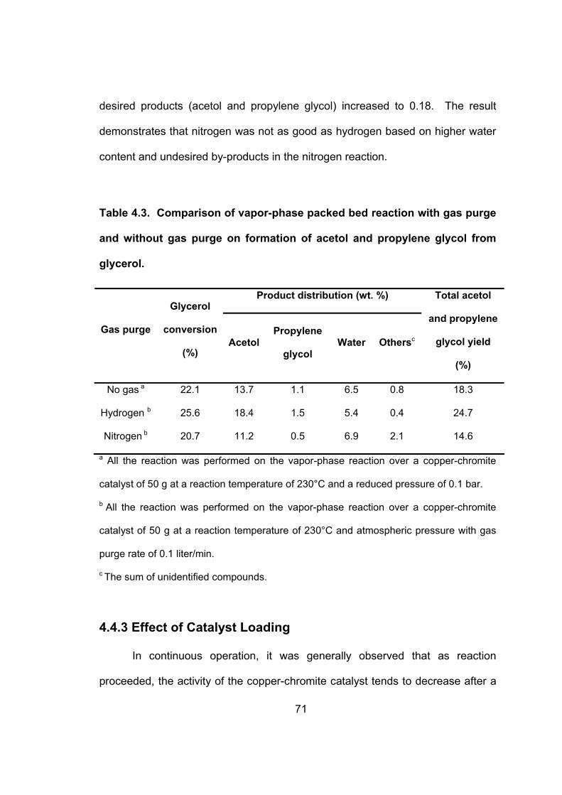
4.4.2 Vapor-Phase Packed Bed Reaction with Gas Purge................................. 69
Page 7
vi
4.4.3 Effect of Catalyst Loading.......................................................................... 71
4.4.4 Effect of Reaction Temperature................................................................. 74
4.4.5 Effect of Hydrogen Purge Rate.................................................................. 75
4.4.6 Catalyst Life............................................................................................... 77
4.4.7 Process Concept ....................................................................................... 77
4.5 Conclusions .................................................................................................. 80
CHAPTER 5 BY-PRODUCT FORMATION IN RESPECT OF OPERATING
CONDITIONS ON CONVERSION OF GLYCEROL TO PROPYLENE GLYCOL
........................................................................................................................... 82
5.1 Formation of Reaction By-products .............................................................. 82
5.2 Experimental Section.................................................................................... 83
5.3 Results and Discussion ................................................................................ 84
5.3.1 Reaction of Glycerol to Propylene Glycol .................................................. 84
5.3.1.1 Trends in 7 Unknown By-products.......................................................... 85
5.3.2 Reaction of Acetol to Propylene Glycol ..................................................... 94
5.3.2.1 Trends in 7 Unknown By-products.......................................................... 95
5.3.3 Reaction of Propylene Glycol to Acetol ................................................... 103
5.3.3.1 Trends in 7 Unknown By-products........................................................ 104
5.4 Conclusions ................................................................................................ 108
CHAPTER 6 PILOT-SCALE STUDY ON THE PRODUCTION OF PROPYLENE
GLYCOL FROM GLYCEROL .......................................................................... 109
6.1 Introduction................................................................................................. 109
6.1.1 Scale-up .................................................................................................. 109
Page 8
vii
6.1.2 Pilot Scale Processing............................................................................. 110
6.1.3 Packed-Bed Exothermic Catalytic Reactor .............................................. 111
6.1.4 Hot Spot................................................................................................... 112
6.1.5 Temperature Control on Packed-Bed Exothermic Catalytic Reactor ....... 113
6.2 Experimental Section.................................................................................. 114
6.2.1 Experimental Setup ................................................................................. 115
6.2.2 Analytical Methods .................................................................................. 116
6.3 Results and Discussion .............................................................................. 117
6.3.1 Shell-and-Tube Packed-Bed Reactor ...................................................... 118
6.3.1.1 Reactor Description .............................................................................. 118
6.3.1.2 Performance ......................................................................................... 120
6.3.2 Tube-Cooled Packed-bed Reactor with Inert Packing ............................. 122
6.3.2.1 Reactor Description .............................................................................. 122
6.3.2.2 Performance ......................................................................................... 123
6.3.2.3 Scalability ............................................................................................. 126
CHAPTER 7 SEPARATION SCHEME AND RELATIVE VOLATILITY
EATIMATION ................................................................................................... 128
7.1 Introduction................................................................................................. 128
7.1.1 Multicomponent Distillation ...................................................................... 128
7.1.2 Fenske-Underwood-Gilliland (FUG) Shortcut Method for Design of
Multicomponent Distillation Columns................................................................ 129
7.2 Problem Statement..................................................................................... 133
7.3 Solution Methods........................................................................................ 134
Page 9
viii
7.3.1 Relative Volatility Calculation and Normal Boiling Point Estimation......... 135
7.3.1.1 General Theory..................................................................................... 135
7.3.1.2 Relative Volatility Calculation................................................................ 136
7.3.1.3 Approximate Normal Boiling Point Estimation ...................................... 139
7.3.2 Distillation Process Modeling Using ChemCAD Simulation Program ...... 142
7.3.2.1 Solution Procedures for Base Case Process........................................ 145
7.3.2.1.1 Simple Distillation Model (FUG shortcut method) .............................. 146
7.3.2.1.2 Rigorous Equilibrium Stage-to-Stage Model (SCDS rigorous method)
......................................................................................................................... 148
7.3.2.1.3 Distillation process with propylene glycol recycle stream .................. 151
7.4 Conclusions ................................................................................................ 155
CHAPTER 8 KINETIC AND EQUILIBRIUM STUDIES OF CONVERSION OF
GLYCEROL TO PROPYLENE GLYCOL IN A PACKED BED REACTOR ..... 157
8.1 Kinetic Studies of Converting Glycerol to Propylene Glycol........................ 157
8.1.1 Initial Reaction Rate ................................................................................ 157
8.1.2 Effect of Reaction Temperature on Rate Constant .................................. 161
8.1.3 Conversion Profiles ................................................................................. 162
8.2 Equilibrium Studies of Converting Acetol to Propylene Glycol.................... 164
8.2.1 Equilibrium Constant ............................................................................... 165
8.2.2 Effect of Temperature on Equilibrium ...................................................... 167
8.2.3 Effect of Pressure on Equilibrium ............................................................ 172
8.2.4 Changes in Equilibrium and Le Châtelier’s Principle ............................... 173
CHAPTER 9 CONCLUSIONS AND RECOMMENDATIONS.......................... 177
Page 10
ix
REFERENCES................................................................................................. 181
APPENDIX ...…………………………………………………………………………187
VITA……………………………………………………………………………………193
Page 11
x
LIST OF TABLES
Table 2.1. Effect of the Contaminants from the Biodiesel Process on the
Formation of Propylene Glycol from Glycerol ........................................ 27
Table 2.2. Summary of the Glycerol Hydrogenolysis Results with the
Addition of Ca(OH)2 in the Phosphate-Containing Glycerol Solution
Prepared by 1 wt. % Phosphate Acid....................................................... 28
Table 2.3. Summary of the Glycerol Hydrogenolysis Results with Different
Amounts of Ca(OH)2 Addition in the Batch HAP
Crystallization/Precipitation System........................................................ 29
Table 2.4. Summary of Glycerol Hydrogenolysis Results of the Effluent
Glycerol Solutions That Passed through the Column with 15 min
Residence time at Different Temperatures.............................................. 30
Table 3.1. Summary of conversion of glycerol, selectivity of acetol and
residue to initial glycerol ratio from glycerol over various metal
catalysts ..................................................................................................... 49
Table 3.2. Comparison of batch reactive distillation and semi-batch
(continuous) reactive distillation on formation of acetol from glycerol50
Table 3.3. Effect of glycerol feed flow rate on conversion of glycerol to
acetol in semi-batch reactive distillation................................................. 52
Table 3.4. Effect of catalyst to glycerol throughput ratio on conversion of
glycerol to acetol in semi-batch reactive distillation.............................. 53
Table 3.5. Effect of initial water content in the glycerol feedstock on
residue formation ...................................................................................... 54
Page 12
xi
Table 4.1. The specification of copper-chromite catalyst. ........................... 63
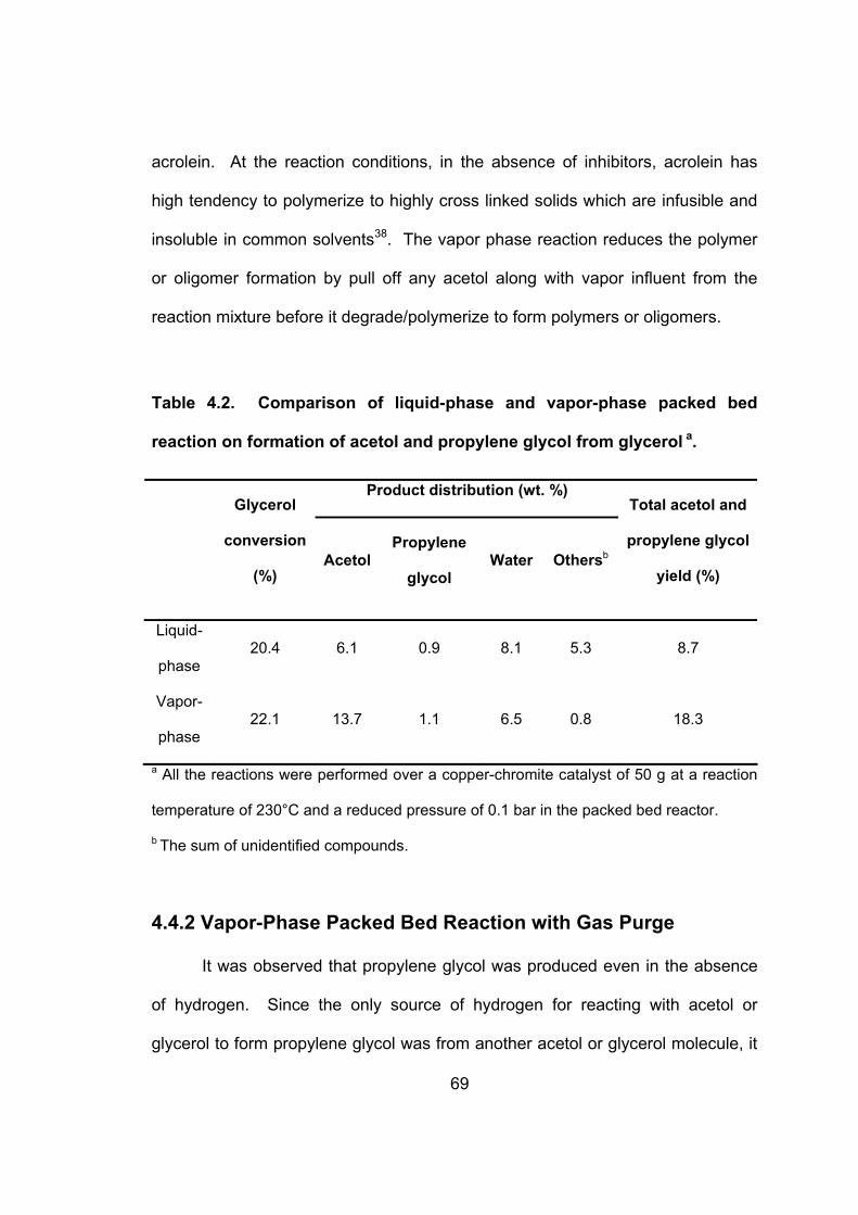
Table 4.2. Comparison of liquid-phase and vapor-phase packed bed
reaction on formation of acetol and propylene glycol from glycerol a.. 69
Table 4.3. Comparison of vapor-phase packed bed reaction with gas purge
and without gas purge on formation of acetol and propylene glycol
from glycerol.............................................................................................. 71
Table 4.4. Effect of catalyst loading on formation of acetol and propylene
glycol from glycerol. ................................................................................. 73
Table 4.5. Effect of reaction temperature on formation of acetol and
propylene glycol from glycerol a. ............................................................. 75
Table 6.1. Comparison of the #1 shell-and-tube and tube-cooled reactors
on converting glycerol to propylene glycol. ......................................... 125
Table 7.1. Problem description: base case process................................... 134
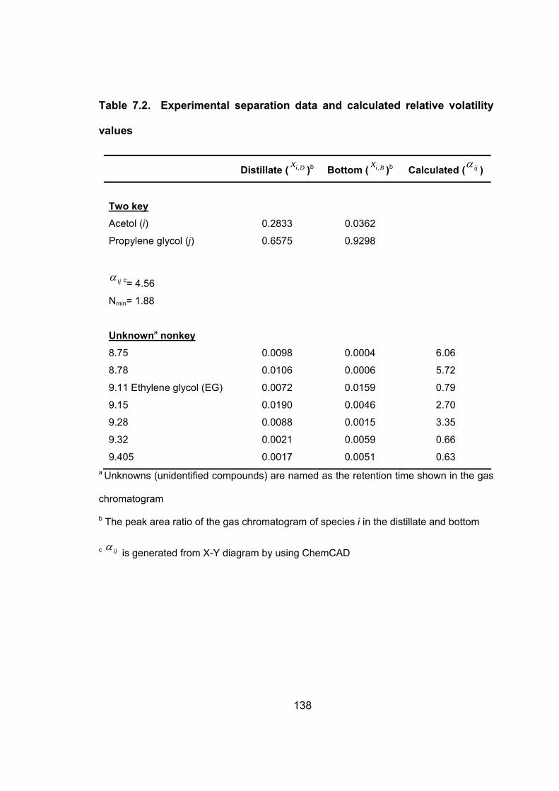
Table 7.2. Experimental separation data and calculated relative volatility
values ....................................................................................................... 138
Table 7.3. Comparison between the true and calculated normal boiling
points........................................................................................................ 142
Table 7.4. The calculated results using Fenske-Underwood-Gilliland
shortcut method ...................................................................................... 148
Table 7.5. Comparison between FUG shortcut and rigorous methods using
ChemCAD................................................................................................. 150
Table 7.6. Comparison between FUG shortcut and rigorous methods on
the improved process using ChemCAD................................................ 154
Page 13
xii
Table 8.1. Effect of reaction temperature on the zero-order rate constant
.................................................................................................................. 162
Page 14
xiii
LIST OF FIGURES
Figure 1.1. Breakout of propylene glycol use. ................................................ 4
Figure 1.2. Proposed reaction mechanism for conversion of glycerol to
propylene glycol. ......................................................................................... 6
Figure 2.1. Example block flow diagram of biodiesel production. ............ 31
Figure 2.2. Reaction profiles of glycerol conversion and yield of propylene
glycol for copper-chromite catalyst at 200 °C and 200 psi hydrogen
pressure. .................................................................................................... 32
Figure 2.3. Summary of the glycerol hydrogenolysis results with different
pH values in the batch HAP crystallization/precipitation system. All
glycerol hydrogenolysis reactions were performed using an 80%
glycerol solution at 200 °C and 200 psi hydrogen pressure for 24 h.... 33
Figure 2.4. Summary of the glycerol hydrogenolysis results of the effluent
glycerol solutions that passed through the column with different
residence times at a constant column temperature of 180 °C. All
glycerol hydrogenolysis reactions were performed using an 80%
glycerol solution at 200 °C and 200 psi hydrogen pressure for 24 h.... 34
Figure 3.1. Proposed reaction mechanism for converting glycerol to acetol
and then to propylene glycol.................................................................... 55
Figure 3.2. Diagram of semi-batch reactive distillation experimental setup.
.................................................................................................................... 56
Figure 3.3. Copper-chromite catalyst reuse for conversion of glycerol to
acetol. All reactions were performed using 5% copper-chromite
Page 15
xiv
catalyst loading in semi-batch reactive distillation with glycerol feed
rate of 33.33 g/h at 240 oC and 98 kPa (vac). ........................................... 57
Figure 4.1. Proposed reaction mechanism for conversion of glycerol to
propylene glycol. ....................................................................................... 62
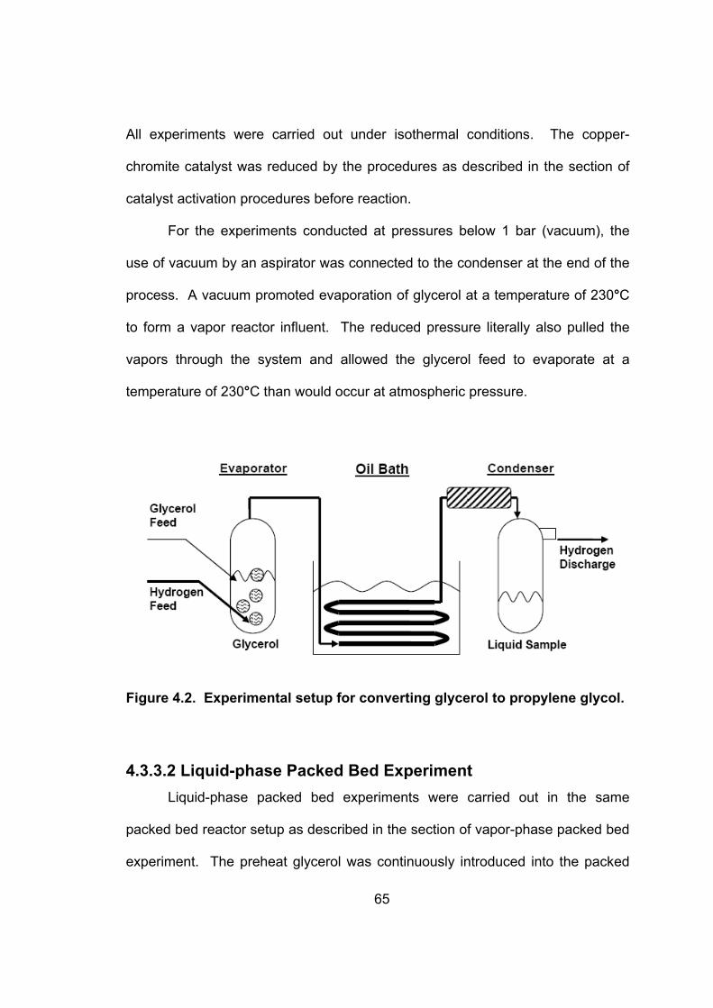
Figure 4.2. Experimental setup for converting glycerol to propylene glycol.
.................................................................................................................... 65
Figure 4.3. Gas chromatogram of the reaction product. .............................. 67
Figure 4.4. Effect of hydrogen purge rate on formation of acetol and
propylene glycol from glycerol. All the reactions were performed on
the vapor-phase reaction over a copper-chromite catalyst of 1160 g at
atmospheric pressure with hydrogen purge........................................... 77
Figure 4.5. Process concept for production of propylene glycerol from
crude glycerol............................................................................................ 80
Figure 5.1. Effect of reaction temperature and pressure on propylene
glycol production from glycerol............................................................... 85
Figure 5.2. Effect of reaction temperature and pressure on unknown by-
product 8.74 formation of the glycerol to propylene glycol reaction
(Data were plotted by 8.74/IS peak area ratio vs. Temperature)............ 87
Figure 5.3. Effect of reaction temperature and pressure on unknown by-
product 8.74 formation of the glycerol to propylene glycol reaction
(Data were plotted by 8.74/PG peak area ratio vs. Temperature) .......... 87
Figure 5.4. Effect of reaction temperature and pressure on unknown by-
product 8.78 formation of the glycerol to propylene glycol reaction
Page 16
xv
(Data were plotted by 8.78/IS peak area ratio vs. Temperature)............ 88
Figure 5.5. Effect of reaction temperature and pressure on unknown by-
product 8.78 formation of the glycerol to propylene glycol reaction
(Data were plotted by 8.78/PG peak area ratio vs. Temperature) .......... 88
Figure 5.6. Effect of reaction temperature and pressure on unknown by-
product 9.11 (EG) formation of the glycerol to propylene glycol reaction
(Data were plotted by 9.11(EG)/IS peak area ratio vs. Temperature) .... 89
Figure 5.7. Unknown by-product 9.11 (EG) formation versus propylene
glycol production of the glycerol to propylene glycol reaction (Data
plotted by 9.11(EG)/IS peak area ratio vs. PG/IS peak area ratio) ......... 89
Figure 5.8. Effect of reaction temperature and pressure on unknown by-
product 9.15 formation of the glycerol to propylene glycol reaction
(Data were plotted by 9.15/IS peak area ratio vs. Temperature)............ 90
Figure 5.9. Effect of reaction temperature and pressure on unknown by-
product 9.15 formation of the glycerol to propylene glycol reaction
(Data were plotted by 9.15/PG peak area ratio vs. Temperature) .......... 90
Figure 5.10. Effect of reaction temperature and pressure on unknown by-
product 9.28 formation of the glycerol to propylene glycol reaction
(Data were plotted by 9.28/IS peak area ratio vs. Temperature)............ 91
Figure 5.11. Effect of reaction temperature and pressure on unknown by-
product 9.28 formation of the glycerol to propylene glycol reaction
(Data were plotted by 9.28/PG peak area ratio vs. Temperature) .......... 91
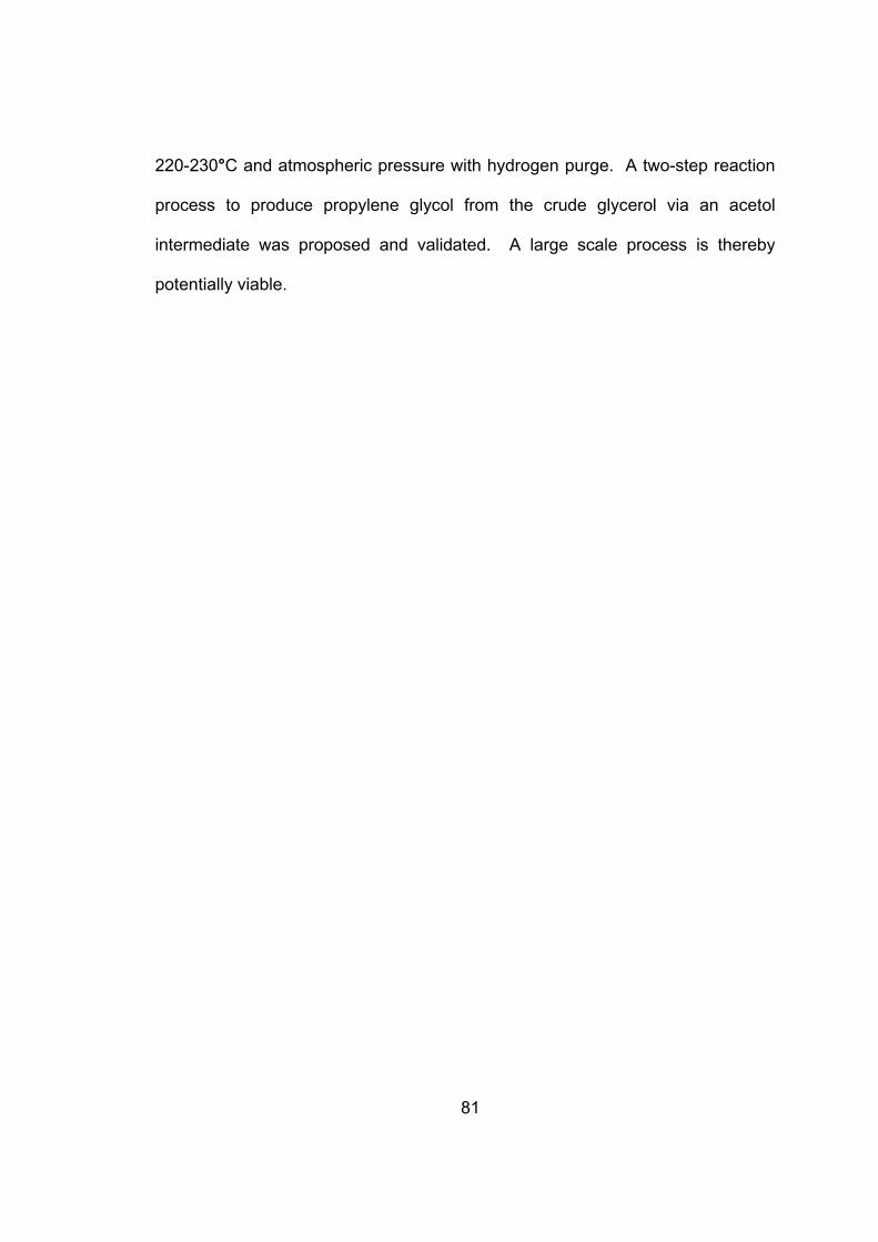
Figure 5.12. Effect of reaction temperature and pressure on unknown by-
Page 17
xvi
product 9.32 formation of the glycerol to propylene glycol reaction
(Data were plotted by 9.32/IS peak area ratio vs. Temperature)............ 92
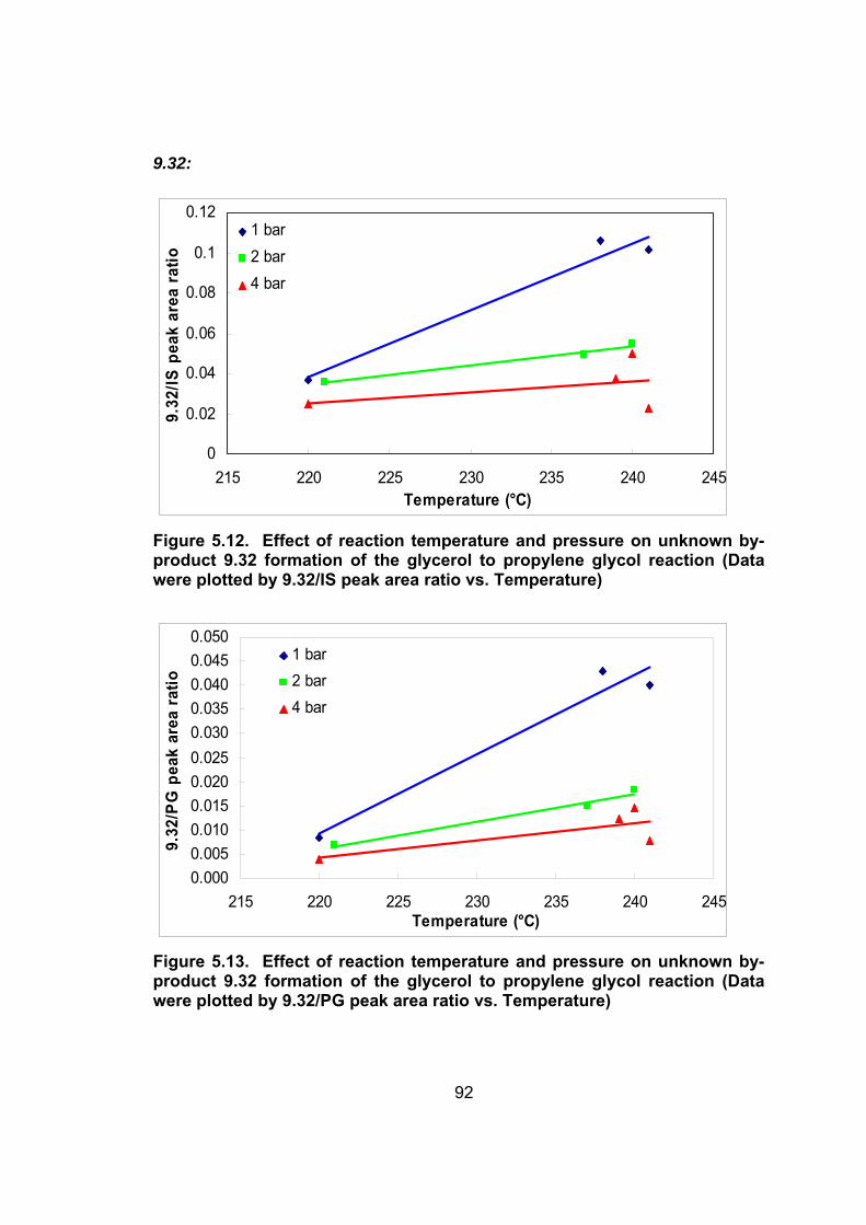
Figure 5.13. Effect of reaction temperature and pressure on unknown by-
product 9.32 formation of the glycerol to propylene glycol reaction
(Data were plotted by 9.32/PG peak area ratio vs. Temperature) .......... 92
Figure 5.14. Effect of reaction temperature and pressure on unknown by-
product 9.405 formation of the glycerol to propylene glycol reaction
(Data were plotted by 9.405/IS peak area ratio vs. Temperature).......... 93
Figure 5.15. Effect of reaction temperature and pressure on unknown by-
product 9.405 formation of the glycerol to propylene glycol reaction
(Data were plotted by 9.405/PG peak area ratio vs. Temperature) ........ 93
Figure 5.16. Effect of reaction temperature and pressure on propylene
glycol production from acetol .................................................................. 94
Figure 5.17. Effect of reaction temperature and pressure on unknown by-
product 8.74 formation of the acetol to propylene glycol reaction (Data
were plotted by 8.74/IS peak area ratio vs. Temperature)...................... 96
Figure 5.18. Effect of reaction temperature and pressure on unknown by-
product 8.74 formation of the acetol to propylene glycol reaction (Data
were plotted by 8.74/PG peak area ratio vs. Temperature) .................... 96
Figure 5.19. Effect of reaction temperature and pressure on unknown by-
product 8.78 formation of the acetol to propylene glycol reaction (Data
were plotted by 8.78/IS peak area ratio vs. Temperature)...................... 97
Figure 5.20. Effect of reaction temperature and pressure on unknown by-
Page 18
xvii
product 8.78 formation of the acetol to propylene glycol reaction (Data
were plotted by 8.78/PG peak area ratio vs. Temperature) .................... 97
Figure 5.21. Effect of reaction temperature and pressure on unknown by-
product 9.11 formation of the acetol to propylene glycol reaction (Data
were plotted by 9.11/IS peak area ratio vs. Temperature)...................... 98
Figure 5.22. Unknown by-product 9.11 (EG) formation versus propylene
glycol production of the acetol to propylene glycol reaction (Data
plotted by 9.11(EG)/IS peak area ratio vs. PG/IS peak area ratio) ......... 98
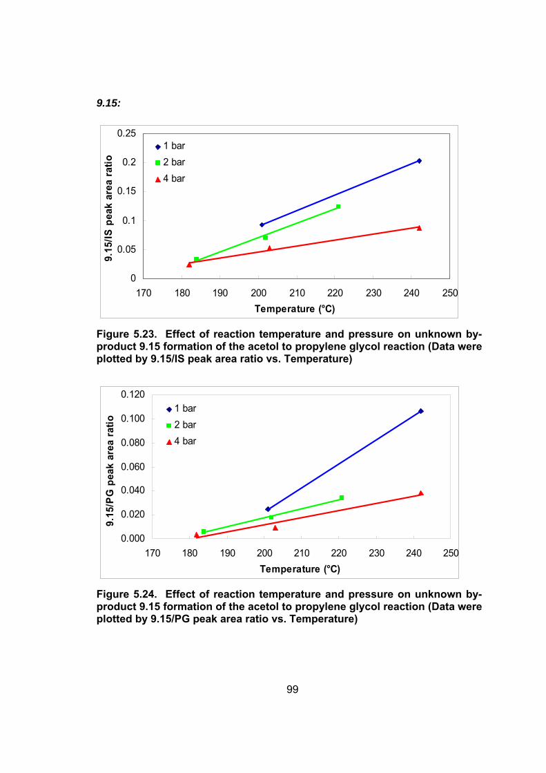
Figure 5.23. Effect of reaction temperature and pressure on unknown by-
product 9.15 formation of the acetol to propylene glycol reaction (Data
were plotted by 9.15/IS peak area ratio vs. Temperature)...................... 99
Figure 5.24. Effect of reaction temperature and pressure on unknown by-
product 9.15 formation of the acetol to propylene glycol reaction (Data
were plotted by 9.15/PG peak area ratio vs. Temperature) .................... 99
Figure 5.25. Effect of reaction temperature and pressure on unknown by-
product 9.28 formation of the acetol to propylene glycol reaction (Data
were plotted by 9.28/IS peak area ratio vs. Temperature).................... 100
Figure 5.26. Effect of reaction temperature and pressure on unknown by-
product 9.28 formation of the acetol to propylene glycol reaction (Data
were plotted by 9.28/PG peak area ratio vs. Temperature) .................. 100
Figure 5.27. Effect of reaction temperature and pressure on unknown by-
product 9.32 formation of the acetol to propylene glycol reaction (Data
were plotted by 9.32/IS peak area ratio vs. Temperature).................... 101
Page 19
xviii
Figure 5.28. Effect of reaction temperature and pressure on unknown by-
product 9.32 formation of the acetol to propylene glycol reaction (Data
were plotted by 9.32/PG peak area ratio vs. Temperature) .................. 101
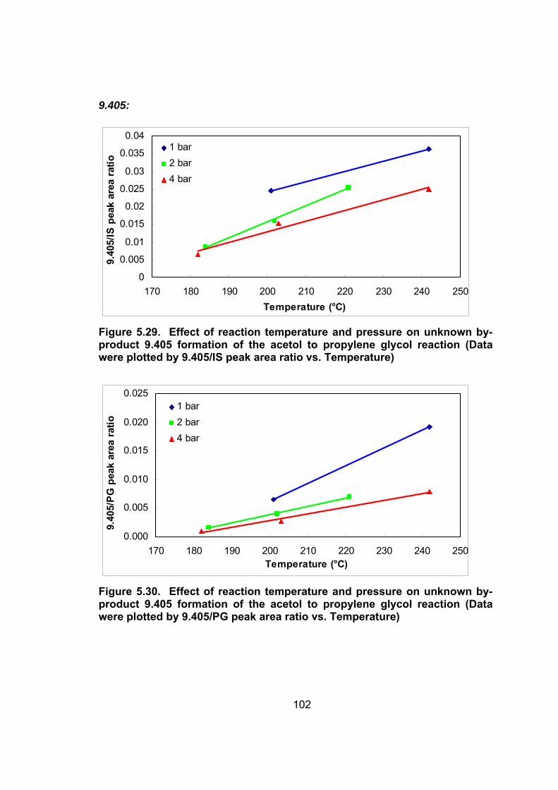
Figure 5.29. Effect of reaction temperature and pressure on unknown by-
product 9.405 formation of the acetol to propylene glycol reaction (Data
were plotted by 9.405/IS peak area ratio vs. Temperature).................. 102
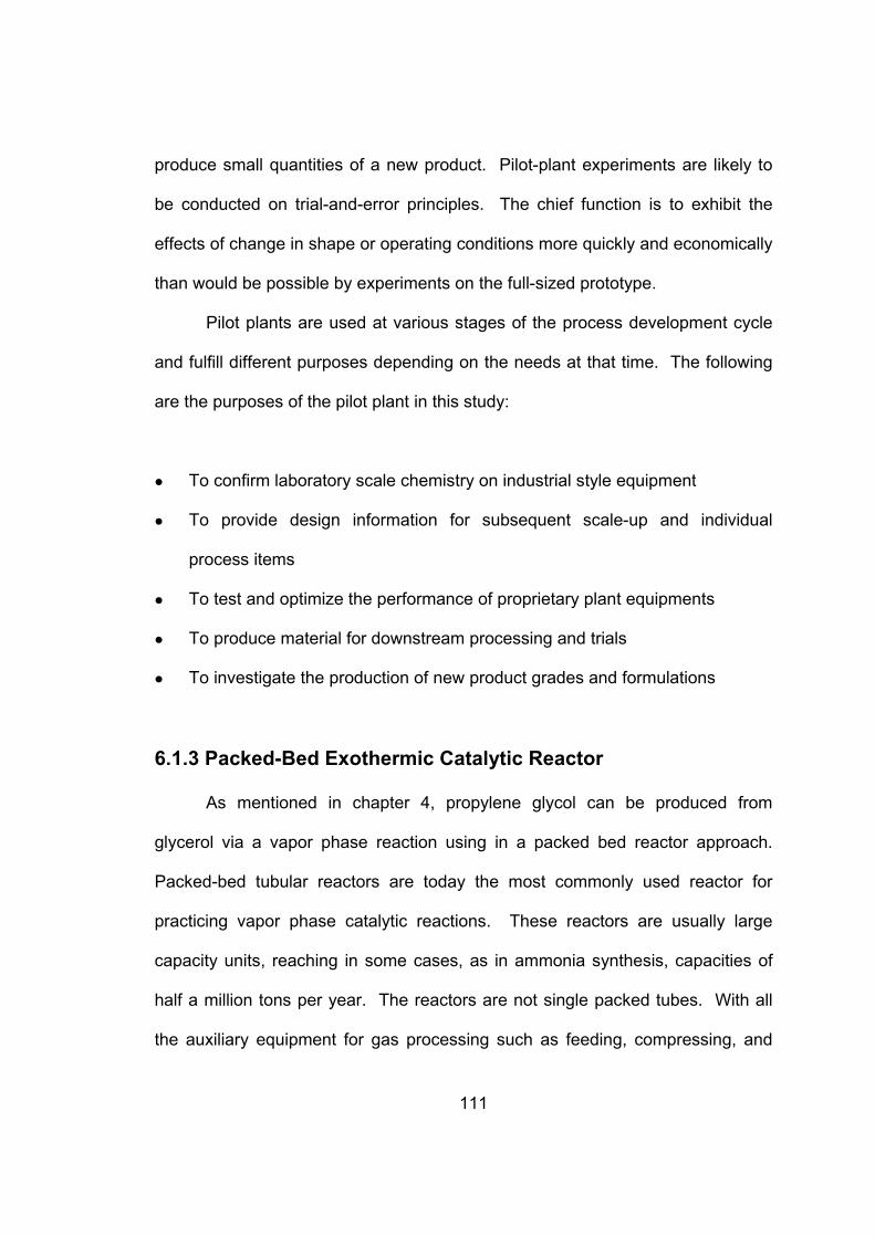
Figure 5.30. Effect of reaction temperature and pressure on unknown by-
product 9.405 formation of the acetol to propylene glycol reaction (Data
were plotted by 9.405/PG peak area ratio vs. Temperature) ................ 102
Figure 5.31. Effect of reaction temperature and pressure on conversion of
propylene glycol to acetol. ..................................................................... 103
Figure 5.32. Effect of reaction temperature and pressure on unknown by-
product 8.74 formation of the propylene glycol to acetol reaction (Data
were plotted by 8.74/IS peak area ratio vs. Temperature).................... 105
Figure 5.33. Effect of reaction temperature and pressure on unknown by-
product 8.78 formation of the propylene glycol to acetol reaction (Data
were plotted by 8.78/IS peak area ratio vs. Temperature).................... 105
Figure 5.34. Effect of reaction temperature and pressure on unknown by-
product 9.15 formation of the propylene glycol to acetol reaction (Data
were plotted by 9.15/IS peak area ratio vs. Temperature).................... 106
Figure 5.35. Effect of reaction temperature and pressure on unknown by-
product 9.28 formation of the propylene glycol to acetol reaction (Data
were plotted by 9.28/IS peak area ratio vs. Temperature).................... 106
Page 20
xix
Figure 5.36. Effect of reaction temperature and pressure on unknown by-
product 9.32 formation of the propylene glycol to acetol reaction (Data
were plotted by 9.32/IS peak area ratio vs. Temperature).................... 107
Figure 5.37. Effect of reaction temperature and pressure on unknown by-
product 9.405 formation of the propylene glycol to acetol reaction (Data
were plotted by 9.405/IS peak area ratio vs. Temperature).................. 107
Figure 6.1. Pilot-scale experimental setup. ................................................. 116
Figure 6.2. Shell-and-tube packed-bed pilot plant reactor......................... 119
Figure 6.3. Axial temperature profile for the #1 shell-and-tube packed-bed
reactor and the tube-cooled packed-bed reactor at 220°C operating
temperature.............................................................................................. 121
Figure 6.4. Stability test of the #1 shell-and-tube packed-bed reactor at
reaction temperature = 220°C; glycerol feed rate = 0.8 kg/hr; hydrogen
flow rate = 50 l/min. ................................................................................. 122
Figure 6.5. Tube-cooled packed-bed pilot plant reactor. ........................... 123
Figure 6.6. Recommended configuration for the tube-cooled packed-bed
reactor. ..................................................................................................... 127
Figure 7.1. Relative volatilities and true boiling points of identified
components ............................................................................................. 141
Figure 7.2. Comparison of true and created pseudo components for the
ethylene glycol-propylene glycol mixture at a pressure of 135mmHg.
The solid line represents the true component and point (■) represents
the created component in ChemCAD .................................................... 144
Page 21
xx
Figure 7.3. Comparison of true and created pseudo components for the
acetol-propylene glycol mixture at a pressure of 135mmHg. The solid
line represents the true component and point (■) represents the
created component in ChemCAD .......................................................... 145
Figure 7.4. Process flow diagram of the base case process with
approximate distribution of components (FUG shortcut method)...... 147
Figure 7.5. Process flow diagram of the base case process (SCDS rigorous
method) .................................................................................................... 149
Figure 7.6. Process flow diagram of the base case process with propylene
glycol recycle (FUG shortcut method)................................................... 152
Figure 7.7. Process flow diagram of the base case process with propylene
glycol recycle (SCDS rigorous method) ................................................ 153
Figure 7.8. Process flow diagram of preliminary design ........................... 156
Figure 8.1. Effect of W/F on glycerol conversion at 220°C and 1 bar........ 159
Figure 8.2. Effect of W/F on glycerol conversion at 230°C and 1 bar........ 160
Figure 8.3. Effect of W/F on glycerol conversion at 240°C and 1 bar........ 160
Figure 8.4. Arrhenius plot of the zero-order rate constant. ....................... 162
Figure 8.5. Reaction Profile for the conversion of glycerol to propylene
glycol at 220°C and 1 bar. ....................................................................... 163
Figure 8.6. Glycerol conversion versus product distribution (PG to acetol
mole ratio) at 220°C and 1 bar. ............................................................... 164
Figure 8.7. Chemical equilibrium constants as a function of temperature.
.................................................................................................................. 171
Page 22
xxi
Figure 8.8. Chemical equilibrium constant as a function of temperature for
the equilibrium reaction of converting acetol to propylene glycol. .... 172
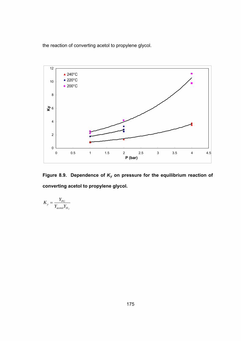
Figure 8.9. Dependence of Ky on pressure for the equilibrium reaction of
converting acetol to propylene glycol. .................................................. 175
Figure 8.10. Dependence of Kp on temperature for the equilibrium reaction
of converting acetol to propylene glycol............................................... 176
Page 23
1
CHAPTER 1
1. INTRODUCTION
1.1 Glycerol By-product from Biodiesel Production
Biodiesel is a generic term that refers to mixed Fatty Acid Methyl Esters
(FAME). Mixed FAMEs, obtained from biogenic fats and oils, are recognized as
a viable alternative fuel for compression ignition (diesel) engines. Biodiesel is
defined as “a substitute or an additive to diesel fuel that is derived from the oils
and fats of plants and animals”.1 There has been a considerable interest in
developing biodiesel as an alternative fuel in recent years because it is a
renewable fuel that is non-toxic, biodegradable and environmentally benign2, 3, 4, 5,
6.
Worldwide biodiesel production is approaching a billion gallons per year.
The U.S. production of biodiesel is 30-40 million gallons, which is expected to
grow at a rate of 50-80% per year, with a projected 400 million gallons of
production by the year 2012. For every 9 kilograms of biodiesel produced, about
1 kilogram of a crude glycerol by-product is formed. With the annual world
biodiesel production expected to increase to over a billion gallons by the end of
this decade, the projected amount of the process’s crude glycerol by-product will
increase to over 100 million gallons per year. The major drawback on biodiesel
commercialization is its high cost when compared to diesel. The production cost
for biodiesel range from $0.65- $1.50 per gallon6. Today, establishing a
technology to utilize this new source of glycerol for biodiesel cost reduction is one
Page 24
2
of the priorities on the minds of biodiesel producers.
1.2 New Use of Glycerol
Chemically glycerol is a tri-basic alcohol and more correctly named 1,2,3-
propanetriol. Most of the larger biodiesel producers purify and refine this crude
glycerol by several steps including vacuum distillation for sale in the commodity
glycerol market. Many smaller plants simply discard the glycerol by-product as a
waste. A primary reason for discarding the glycerol is because refining the crude
glycerol which contains residual catalysts, water and other organic impurities is
too complex and expensive to handle for small scale producers in their available
limited facilities. Hence, 50% of the total crude glycerol by-product that is
generated is disposed of and only the remaining is sold at a very minimal price.
Today, with plenty of glycerol available to the world market, prices and
U.S. exports have declined. Prices in the glycerol market will continue to drop
with an over saturated market and new supplies of glycerol coming into the
market from the burgeoning biodiesel industry. The price of glycerol is already
(2005) about half the price of past averages in Europe where biodiesel
production exceeds 400 million gallons per year. Increased biodiesel production
is expected to further suppress glycerol prices. In addition, glycerol can be a
platform chemical that serves as an important biorefinery feedstock, and so,
conversion of glycerol to other commodity chemicals is desirable.
Converting glycerol to propylene glycol is one of the potential solutions to
this problem. Propylene glycol demand is not only twice that of glycerol demand,
Page 25
3
but also the opportunity exists to market propylene glycol in the antifreeze market
as an alternative to ethylene glycol. This technology also could be used in
biodiesel production plants to increase profitability. The preferred technology
would be to convert crude natural glycerol with high selectivity to propylene glycol
at moderate temperatures and pressures.
1.3 Applications of Propylene Glycol
Propylene glycol (CH3CHOHCH2OH), also named as 1,2 propanediol, is a
three carbon diol with two hydroxyl groups on the 1 and 2 carbon. It is a major
commodity chemical that some typical uses of propylene glycol are in
unsaturated polyester resins, functional fluids (antifreeze, de-icing, and heat
transfer), pharmaceuticals, foods, cosmetics, liquid detergents, tobacco
humectants, flavors and fragrances, personal care, paints and animal feed.
There are approximately 1.3 billion pounds of propylene glycol produced each
year in the U.S. The pie chart shown in Figure 1.1 shows the breakout of the
many uses of propylene glycol. As shown 23% or approximately 300 million
pounds of the market is devoted to functional fluids such as antifreeze and
deicers.
Unlike ethylene glycol, propylene glycol is not toxic when ingested.
Currently, the commercial route to produce propylene glycol is by the hydration of
propylene oxide derived from propylene by either the chlorohydrin process or the
hydroperoxide process. In the antifreeze market, propylene glycol produced from
glycerol would be a sustainable, domestically-produced and non-toxic alternative
Page 26
4
to ethylene glycol.
Figure 1.1. Breakout of propylene glycol use.
1.4 Improved Process for Converting Glycerol to Propylene
Glycol
The hydrogenolysis of glycerol to propylene glycol has been long known.
Conventional processing of glycerol to propylene glycol uses metallic catalysts
and hydrogen as reported in several United States patents 7 , 8 , 9 , 10 . These
research efforts reported the satisfactory results of converting glycerol to form
propylene glycol. However, there are concerns related to commercial viability,
for example, high temperatures and high pressures, low production efficiency
from using diluted solutions of glycerol, low selectivity to propylene glycol, and
Page 27
5
high selectivity to ethylene glycol and other by-products. Higher process
pressures translate to higher capital costs.
The benefits of highly selective conversion to propylene glycol go beyond
reducing the cost of glycerol feed stock. Patent literature typically reports
producing mixtures containing at least 1 part of ethylene glycol (or other glycol)
for every 3 parts of propylene glycol. These large amounts of by-product dictate
that additional distillation capacity must be added to the process to purify the
propylene glycol to market specifications. Separation of propylene glycol and
ethylene glycol is costly and difficult because of the close proximity of their
boiling points. This additional separation process increases capital costs and
decreases the process profitability.
In earlier work the novel reaction mechanism for converting glycerol to
propylene glycol via a reactive intermediate was purposed as shown in Figure
1.211. Relatively pure acetol was isolated from dehydration of glycerol as the
transient intermediate indicates that the reaction process for producing propylene
glycerol with high yield and selectivity can be done in two steps12. The first step
on this proposed reaction mechanism is an irreversible reaction of glycerol to
acetol. The second step of the reaction (acetol to propylene glycol) is expected
to be equilibrium limited. The technology has been developed to the point of
commercial viability for converting glycerol to propylene glycol based on copper-
chromite catalysis and a two-step synthesis involving the novel reactive-
distillation and acetol hydrogenation13. The preferred method for this reaction
includes a vapor-phase reaction over a copper-chromite catalyst in a packed bed
Page 28
6
reactor. In the presence of hydrogen, the vapor phase reaction approach allows
glycerol to be converted to propylene glycol in a single reactor.
CH2
OHCH CH2
OH OHCH2
OHC CH3
OCH2
OHCHOH
CH3
-H2O H
Glycerol Acetol Propylene Glycol
+ 2
Dehydration Hydrogenation
(Intermediate)
Figure 1.2. Proposed reaction mechanism for conversion of glycerol to
propylene glycol.
1.5 Research Objectives
This dissertation is focused on developing a method that is applicable to
the industrial-scale production of propylene glycol from glycerol with considerably
high conversions and yields. The primary goal of this study is to convert glycerol
to propylene glycol at lower temperatures and pressures than the multiple
processes reported in the patent literature. A secondary goal is to attain high
selectivity to propylene glycol with little selectivity towards ethylene glycol and
other by-products.
This dissertation is written as a series of 9 chapters. The research can be
broadly divided into 7 topics. Preceding each topic is a brief introduction
describing the background, scope and objective of this research. Each paper
has its own introduction, methods, materials, results and discussion, and
Page 29
7
conclusions as well as figures and tables. For the clarity of presentation, the
organization of this dissertation is presented in chronological order.
In chapter 2, the removal of sodium from glycerol solutions by
crystallization/precipitation of hydroxyapatite (HAP) through the co-addition of
lime [Ca(OH)2] and phosphoric acid is evaluated as a means to remove soluble
catalyst from the glycerol by-product of biodiesel production. The suitability of
the resulting product is evaluated as a hydrogenolysis feedstock for producing
propylene glycol. The continuous removal of phosphate by a lime packed
column method is also evaluated for process scale-up considerations.
In chapter 3, dehydration of glycerol is performed in the presence of
various metallic catalysts including alumina, magnesium, ruthenium, nickel,
platinum, palladium, copper, raney nickel, and copper-chromite catalysts to
obtain acetol in a single stage reactive distillation unit under mild conditions. The
effects of operation mode, catalyst selection, glycerol feed flow rate, catalyst
loading and initial water content are studied to arrive at optimum conditions. The
acetol from this reaction readily hydrogenates to form propylene glycol providing
an alternative route for converting glycerol to propylene glycol.
Chapter 4 describes the investigations carried out on the vapor phase
hydrogenolysis of glycerol to propylene glycol over a copper-chromite catalyst in
a continuous packed bed flow reactor. The effects of reaction method (liquid-
phase versus vapor-phase mode), vapor-phase reaction with gas purge, reaction
temperature, catalyst loading, and hydrogen purge rate are studied to arrive at
optimum conditions. The production scheme that has application for production
Page 30
8
of propylene glycol from crude glycerol containing various soluble salts is also
discussed.
Chapter 5 focuses on reaction selectivity and unknown by-product
formation. Propylene glycol and seven of the most prominent unknown by-
products are chosen to carry out the study where the trends are studied in
relation to propylene glycol production and reaction operating conditions.
The process scalability and pilot-scale testing are presented in chapter 6.
Two types of packed bed reactors, the shell-and-tube packed-bed reactor and
the tube-cooled packed-bed reactor, are employed to discuss their merits and
drawbacks for production of propylene glycol from glycerol.
In chapter 7, the relative volatilities of seven unknown by-products
calculated from experimental separation data are presented. The FUG shortcut
method and rigorous model used for modeling this multicomponent distillation
process are also discussed.
The objective of chapter 8 is to study the kinetics of converting glycerol to
propylene glycol for process design, control and optimization. Another important
corollary to this chapter is to attempt to control the chemical equilibrium—varying
the conditions under which the reaction occurs can vary the amounts of
intermediate (acetol) and final product (propylene glycol) present at equilibrium.
Finally, chapter 9 describes conclusions, recommendations, and several
suggested future directions for additional research. The results will improve our
understanding of the catalytic conversion of glycerol to propylene glycol.
Page 31
9
CHAPTER 2
2. REMOVAL OF RESIDUAL CATALYST FROM
SIMULATED BIODIESEL’S CRUDE GLYCEROL
FOR GLYCEROL HYDROGENOLYSIS TO
PROPYLENE GLYCOL
This research paper was published as:
Removal of Residual Catalyst from Simulated Biodiesel's Crude
Glycerol for Glycerol Hydrogenolysis to Propylene Glycol,
Chuang-Wei Chiu, Mohanprasad A. Dasari, Willam R. Sutterlin,
Galen J. Suppes*, Industrial & Engineering Chemistry Research
(2006), 45(2), 791-795.
Page 32
10
2.1 Abstract
The removal of sodium from glycerol solutions by
crystallization/precipitation of hydroxyapatite (HAP)through the co-addition of
lime [Ca(OH)2] and phosphoric acid was evaluated as a means to remove soluble
catalyst from the glycerol byproduct of biodiesel production. Phosphate ions
precipitated as hydroxyapatite upon reacting with calcium and hydroxide ions.
Seed crystals and pH impacted crystallization.
The yield decreased due to the polymerization of glycerol at high pH
values (pH ≥ 11). The continuous removal of phosphate by a lime packed
column method was also evaluated for process scale-up considerations. Higher
temperatures favored the phosphate removal efficiency with higher temperatures
raising the pH and the supersaturation region of the respective effluents to the
desired level for HAP crystallization/precipitation.
The suitability of the resulting product was evaluated as a hydrogenolysis
feedstock for producing propylene glycol. The yield of propylene glycol
increased with increasing filtrate pH.
Keywords: sodium, phosphate, glycerol, crystallization/precipitation,
hydroxyapatite, lime, hydrogenolysis, propylene glycol, pH, packed column
Page 33
11
2.2 Introduction
With the annual world production of biodiesel expected to increase to over
four billion liters by the end of this decade, the projected amount of the crude
glycerol byproduct of the process will increase to over 400 million liters per year.
For larger biodiesel facilities that refine and sell glycerol, the increased glycerol
supply has resulted in lower glycerol prices. Many smaller plants simply discard
the glycerol byproduct as a waste. A primary reason for discarding the glycerol is
the 5-15% (water-free basis) of soluble salts that can be costly to remove.
The traditional method of removing salts from crude glycerol is to
evaporate the glycerol from nonvolatile salts in a flash-separation process. While
flash-separation processes are effective, they present capital, maintenance, and
utility costs. The purpose of this paper is to evaluate alternative salt removal
methods and to evaluate the compatibility of these removal methods with
converting the glycerin to propylene glycol over a copper-chromite catalyst.
In the production of biodiesel, a catalyst is used to promote
transesterification, producing methyl esters (biodiesel) and a glycerol byproduct
along with soaps from residual free fatty acids and water. The catalysts are
typically base catalysts such as sodium hydroxide or other alkali metal
hydroxides14, 2, 3, 5. A biodiesel plant that utilizes base catalysis can be described
as a succession of different sections and is presented in Figure 2.1. At high
conversions, the biodiesel and glycerol phases are immiscible. Most unreacted
catalysts and soaps (base-neutralized fatty acids) are preferentially distributed
into the glycerol phase4.
Page 34
12
After reaction, the biodiesel is typically decanted from the glycerol phase.
For the biodiesel’s crude glycerol byproduct, the treatment phase generally
involves neutralization and recycling of the unreacted methanol, either of which
could occur before or after decanting the biodiesel from the glycerol.
Hydrochloric and sulfuric acids are commonly used to neutralize the catalyst after
reaction to reduce the amount of soaps (potassium or sodium salts of free fatty
acids) that adversely impact separation and represent a loss of yield.
Larger biodiesel facilities often refine the glycerol for sale in the
commodity glycerol market. However, the price of glycerol is already (in 2005)
about half the price of past averages in Europe, where biodiesel production
exceeds 1600 million liters per year. Increased biodiesel production is expected
to further suppress glycerol prices, and so, conversion of glycerol to other value-
added consumer products is desirable. The hydrogenolysis of biodiesel’s crude
glycerol to propylene glycol is one process being evaluated to increase the
profitability of biodiesel production.
2.2.1 Hydrogenolysis Catalysts
Propylene glycol can be produced by hydrogenating glycerol only with a
highly selective hydrogenolysis catalyst. In general, the alcohol groups are more
stable against hydrogenolysis than carbon π-bonds and do not readily react at
normal hydrogenating conditions. In a previous study, the authors showed that
copper-containing catalysts of different composition are potentially good catalysts
for this purpose11. These catalysts exhibit poor hydrogenolytic activity toward C-
Page 35
13
C bonds and efficient activity for C-O bond hydro-dehydrogenation.15, 16 However,
these catalysts are very sensitive to typical catalyst poisons such as S, Cl, and
P.17
The salts found in biodiesel’s crude glycerol typically act as
hydrogenolysis catalyst poisons, causing deactivation. The primary objective of
the research described in this paper was to identify cost-effective methods
(alternative to refining) to neutralize or remove the catalyst and/or salts from
biodiesel’s crude glycerol in a manner that does not lead to hydrogenolysis
catalyst deactivation.
The chlorides can be removed with a chloride absorbent. The sulfates
can be eliminated by addition of barium hydroxide to form insoluble barium
sulfate. While it is technically feasible to remove chlorides and sulfates, it is
economically prohibitive. Phosphates are possibly the easiest and most
economical anions to remove from solution and were the emphasis of the current
study.
2.2.2 Phosphate Crystallization and Precipitation
Considerable worldwide research has been undertaken on phosphate
removal technologies. The technical feasibility of phosphate crystallization and
precipitation as a unitary process for wastewater treatment has been
demonstrated by Zoltek;18 Hirasawa, Shimada and Osanai;19 Joko20 and Van Dijk
and Braakensiek21. This same approach should also be effective for removing
phosphate salts from the biodiesel’s crude glycerol in the existing biodiesel
Page 36
14
facilities.
Crystallization can be categorized into two processes: nucleation and
growth. For precipitation, both nucleation and growth take place simultaneously
where there are only small concentrations of seed crystals; this is also referred to
as spontaneous or homogeneous crystallization.22 Crystallization/precipitation of
hydroxyapatite (HAP), Ca5 (PO4)3OH, in an aqueous solution is fundamental to
this phosphate removal method and is summarized by equation 1. The relative
insolubility of HAP is due to its thermodynamic stability at pH’s above 6.8.23
(1)
Kaneko et al.24 reported the special affinity that crystals have for phosphate. The
result is explained by a chemical reaction between the phosphate ions and the
surface of the seed materials. This crystallization/precipitation of HAP on a seed
crystal is commonly influenced by the nature of the seed crystal, the phosphate
concentration, the calcium ion concentration, and the pH value. Research work
was conducted to remove the phosphate anions from an aqueous glycerol
solution by a crystallization/precipitation reaction with calcium ions as the seed
crystal material coexisting in the solution. Several types of HAP salts will form
that incorporate sodium, and so, this is an effective means to remove both the
phosphorus and the sodium from the system.
To determine the optimal operation parameters for effective phosphate
removal from aqueous glycerol solutions for subsequent hydrogenolysis of
3HPO42- + 5Ca2+ + 4OH- Ca5(PO4)3OH + 3H2O
Page 37
15
glycerol to propylene glycol, sets of 50 g of phosphate-containing glycerol
solutions were contacted with lime [Ca(OH)2] by a batch-stirred reactor and a
continuous packed column. The neutralized glycerol solutions were subjected to
an autoclave reactor to perform the glycerol hydrogenolysis reaction using a
copper-chromite catalyst at a hydrogen pressure of 200 psi and a temperature of
200 oC.
In the broader sense, apatite salts are a category of calcium-phosphate
salts known to have low solubility. In this paper, we hypothesized that calcium-
sodium-phosphate salts can be formed that have low solubilities and
processabilities. In this study, sodium hydroxide was neutralized with phosphoric
acid in aqueous glycerol solutions by the crystallization/precipitation of HAP
using lime. The susceptibility of the glycerol was then evaluated in a
hydrogenolysis reaction.
2.3 Experimental Section
2.3.1 Materials
Glycerol (99.9%), sodium hydroxide pellets, calcium hydroxide, and
phosphoric acid (85%) were purchased from Fisher Scientific Co. (Fairlawn, NJ).
Sodium monobasic phosphate (98%), sodium dibasic phosphate (98%), copper-
chromite catalyst, and lime had an approximately mean particle size of 100 mesh
and were purchased from Sigma-Aldrich (Milwaukee, WI). High purity grade
hydrogen was obtained from Praxair.
Page 38
16
2.3.2 Experimental Procedures
An 80% glycerol solution with 20% water was mixed with 4% sodium
hydroxide in a glass flask for about 30 min at 50 oC. An 85% phosphoric acid
solution was added to the mixture to neutralize it until a pH of 5.5 was reached.
The phosphate-containing glycerol solution was contacted with excess lime
through batch reactions and lime-packed columns in order remove the phosphate
through crystallization/precipitation.
The batch crystallization/precipitation experiments were carried out in 200
mL glass flasks. Varying amounts of lime were added to a 50 g phosphate-
containing glycerol solution as the seeding material and to adjust the pH of the
glycerol solution. The change in pH with time was monitored with a pH meter.
Glycerol solutions were maintained above constant pH values by the addition of
lime, and the addition volume was recorded. The solution was continuously
stirred at a constant speed of 250 rpm with a magnetic stirrer at a constant
temperature of 50 oC. After stirring for predetermined times, the solution was
vacuum-filtered.
Column removal experiments were carried out in a stainless steel column
(i.d. 30 mm, length 150mm) equipped with an external heating tape for the
heating system. The column packed with 15 g of lime was connected to a
peristaltic high-performance liquid chromatography (HPLC) pump. The 50 g
phosphate-containing glycerol solution was pumped in a downward direction
through the column. The temperature of the column was controlled by the
CAMILE 2000 control and data acquisition system using TG 4.0 software. The
Page 39
17
residence time was adjusted by proper control of the flow rate.
After the glycerol solutions were treated through the batch or column
methods, they were placed into the autoclave for the subsequent hydrogenolysis
of glycerol to form propylene glycol. All reactions were carried out in a stainless
steel multi-autoclave reactor capable of performing eight reactions
simultaneously. Each reactor has a capacity of 150 mL and is equipped with a
stirrer, a heater, and a sample port. The temperatures of the reactors were
controlled by the CAMILE 2000 control and data acquisition system using TG 4.0
software. The reactors were flushed several times with nitrogen followed by
hydrogen. Then, the system was pressurized with hydrogen to the necessary
pressure and heated to the desired reaction temperature. The speed of the
stirrer was set to be constant at 100 rpm throughout the reaction. The copper-
chromite catalyst used in this study was reduced prior to the reaction by passing
a stream of hydrogen over the catalyst bed at 300 oC for 4 h.
2.3.3 Analytical Methods
Reaction product samples were taken after 24 h of reaction time, cooled to
room temperature, and centrifuged using an IEC (Somerville, MA) Centra CL3R
centrifuge to remove the catalyst. These samples were analyzed with a Hewlett-
Packard 6890 (Wilmington, DE) gas chromatograph equipped with a flame
ionization detector. Hewlett-Packard Chemstation software was used to collect
and analyze the data. A Restek Corp (Bellefonte, PA) MXT® WAX 70624 gas
chromatography (GC) column (30m x 250 μm x 0.5μm) was used for separation.
Page 40
18
A solution of n-butanol with a known amount of internal standard was
prepared a priori and used for analysis. The samples were prepared for analysis
by adding 0.1 mL of product sample to 1 mL of stock solution in a 2 mL glass vial.
A 2 μL portion of the sample was injected into the column. The oven
temperature program consisted of the following segments: start at 45 °C (0 min),
ramp at 0.2 °C /min to 46 °C (0 min), and ramp at 30 °C /min to 220 °C (2.5 min).
Using the standard calibration curves that were prepared for all the components,
the integrated areas were converted to weight percentages for each component
present in the sample.
For each data point, the theoretical yield of propylene glycol was
calculated. The theoretical yield is defined as the ratio of the number of moles of
propylene glycol produced to the theoretical number of moles of propylene glycol
that would be produced at 100% conversion. Conversion of glycerol is defined
as the ratio of the number of moles of glycerol consumed in the reaction to the
total moles of glycerol initially present.
2.4 Results and Discussion
2.4.1 Reaction Profiles of Hydrogenolysis of Glycerol to
Propylene Glycol
Earlier work in our group has demonstrated that copper or copper-based
catalysts exhibit higher selectivity toward propylene glycol with little or no
selectivity toward ethylene glycol and other degradation byproducts11. Figure 2.2
shows the reaction profiles of glycerol conversion and the yield of propylene
Page 41
19
glycol with time at a temperature of 200 °C and 200 psi hydrogen pressure for
the copper-chromite catalyst using an 80% glycerol solution. It can be seen that
an equilibrium glycerol conversion of 54.8% was reached at 24 h with a total
theoretical yield of 46.6%. Figure 2 also provides a baseline for the copper-
chromite catalyst in the absence of all salts.
2.4.2 Effect of Residual Salts on Glycerol Hydrogenolysis
To evaluate the effect of residual salts from the biodiesel process on the
glycerol hydrogenolysis reaction, reactions were carried out by simulating crude
glycerol by the addition of sodium hydroxide, phosphoric acid, sodium
phosphates (Na2HPO4 and NaH2PO4), and lime. Table 2.1 provides the
summary of the conversions of the 80% glycerol solution with different salts at
200 °C and 200 psi hydrogen pressure using the copper-chromite catalyst. As
expected, trace amounts of phosphate ions in the glycerol solution negatively
affected the hydrogenolysis reactivity of the copper-chromite catalyst. There was
no conversion observed with the addition of small amounts of sodium
phosphates and phosphoric acid. This indicates that phosphates react with or
irreversibly adsorb onto active sites to deactivate the catalyst. The presence of
sodium hydroxide decreased the yield of propylene glycol due to the formation of
degradation reaction products resulting in the polymerization of glycerol at high
pH values. The data in Table 2.1 also show that the addition of lime, owing to its
low solubility in glycerol solution, may also reduce the hydrogenolysis activity of
copper-chromite due to catalyst site blockage with physical adsorption of the
Page 42
20
insoluble calcium component.
Lime was selected for the phosphate removal material because it contains
water-soluble calcium which reacts with the phosphate ion to form insoluble
crystalline calcium phosphates, mainly HAP, and also because it can be a
seeding crystal material due to its fine particle size. Experiments were performed
in the batch mode to evaluate phosphate removal for the phosphate-containing
glycerol solution with 1 wt % straight phosphoric acid by the addition of lime, as
shown in Table 2.2. Lime effectively neutralizes the phosphoric acid, as shown
by an increased yield of propylene glycol to 37.6% in the absence of sodium salts.
These data indicate that phosphoric acid and lime can be used to improve the
viability of crude glycerol as a hydrogenolysis feedstock.
2.4.3 Removal of Phosphate in Batch Reactors
The effects of the filtrate pH and the lime addition on the HAP
crystallization/precipitation system were investigated by determining the yield of
propylene glycol on hydrogenolysis of glycerol.
2.4.3.1 Effect of Filtrate pH Figure 2.3 shows the effect of the pH value on the HAP
crystallization/precipitation system for phosphate removal. The yield of
propylene glycol is plotted as a function of the batch reaction time with different
pH values of 7.5, 9, and 10. Both the yield and the reaction rate increased with
increasing pH.
Page 43
21
The yield of propylene glycol from glycerol hydrogenolysis is increased
with increasing pH of the HAP crystallization/precipitation system from 14.3% at
pH 7.5 to 32.2% at pH 10.5 after 120 min. An explanation for these trends is that
the HAP continues to poison the catalyst—eventually poisoning all active sites.
Higher pH’s drive the precipitation of the HAP at the expense of increasing
soluble base concentrations—apparently the soluble base (being low due to the
low solubility of Ca(OH)2) is less detrimental than the soluble anions of HAP.
2.4.3.2 Effect of Lime Addition Table 2.3 summarizes the glycerol hydrogenolysis results of propylene
glycol formation with different amounts of lime addition in the batch HAP
crystallization/precipitation system. The amounts of lime added to obtain the
indicated pH levels of mixtures containing 50g of the phosphate-containing
glycerol solution in the batch HAP crystallization/precipitation system after 120
min of mixing are also provided.
In general, a higher yield of propylene glycol can be obtained at a higher
dosing of lime since the phosphate removal through HAP precipitation is
enhanced with a high calcium concentration and a raised pH level.25 However,
the yield of propylene glycol increased until 29.45 g (pH 10.5) of lime was added
and began to decrease as the dosing was increased further. This decrease in
the yield of propylene glycol with calcium hydroxide dosing over 30 g (pH ≥ 11) is
due to glycerol polymerization at high pH values.26
Page 44
22
2.4.4 Removal of Phosphate by a Packed-Column Method
Due to the low solubility of lime, it is possible to remove phosphate from
solution by passing the solution through a column packed with lime. In these
experiments, the effects of the residence time and the column temperature were
determined.
In these studies, the glycerol was passed through a column containing
sodium hydroxide that had been neutralized with phosphoric acid. The objective
was to form HAP in the column which would then precipitate from solution.
Hydrogenolysis was then performed on the column effluent to evaluate how
effectively the more soluble sodium phosphate salts had been removed.
2.4.4.1 Effect of Residence Time In Figure 2.4, the yield of propylene glycol is plotted as a function of
glycerol that had flowed through the column at different flow rates to induce
different residence times for the precipitation process. The column temperature
was 180 oC, and the hydrogenolysis conditions are the same as those previously
used.
A gradual increase in the yield of propylene glycol was observed as the
column residence time increased to 10 min asymptotically approaching a yield of
28%. This maximum yield is similar to that obtained for the batch results of
Figure 2.3.
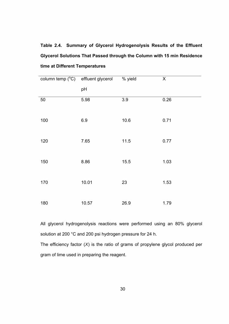
2.4.4.2 Effect of Column Temperature The temperature of 180 oC, as used for the data reported in Figure 2.4,
Page 45
23
was determined by a series of screening studies through the column. In these
screening studies, the glycerol solutions were passed through a heated column
at temperatures of 50, 100, 120, 150, 170, and 180 oC. Glycerol hydrogenolysis
reactions were preformed with the effluent glycerol solutions to identify the
impact of temperature on the crystallization/precipitation of HAP in the column.
Table 2.4 shows the hydrogenolysis results of the effluent glycerol solutions
through the column at different temperatures. The yield of propylene glycol
increased with increasing column temperature. A 26.9% yield of propylene glycol
was obtained when the phosphate-containing glycerol solution flowed through a
180 oC column.
These results indicate that high phosphate removal efficiency can be
obtained from a column with the removal efficiency highly dependent on the
precipitation temperature. High temperatures increase the solubility of lime and
possibly the rate of solution, resulting in higher pH values.
The formation of HAP in aqueous solutions takes place following the
development of supersaturation. Also, the crystallization of HAP should occur in
the metastable supersaturated region of HAP.27 Kaneko et al.24 described the
operating conditions that should be set up in the metastable supersaturated
region close to the super solubility curve in order to induce phosphate
crystallization on the seed crystal. However, increasing temperature contributes
to the solution supersaturation development and to a metastable supersaturated
region, because the sparingly soluble HAP has a reverse solubility. In other
words, a driving force that provides a pH and solution supersaturation adjustment
Page 46
24
is created by high temperature operation to crystallize the phosphate on the lime
bed.
2.4.5 Efficiency Factor Comparison
The following expression (equation 2) was used to quantify the efficiency
of lime consumption for phosphate removal as an easy comparison of the
experiments.
nconsumptioLimeglycolpropyleneofYieldX =
(2)
The efficiency factor X was calculated from the batch and column results with a
high value of X indicating more effective use of the lime. At a pH value of 9 in the
batch and column experiments, an X value of 1.03 was obtained at a residence
time of 15 min and 150 oC in the column experiment compared to 1.77 with 120
min in the batch experiment. The X value gradually increased as the column
temperature increased (see Table 2.4). A maximum X value of 1.79 was
achieved at the column temperature of 180 oC.
The column precipitation method exhibited an advantage over batch
precipitation with respect to the efficiency of lime utilization. In the batch
experiments (Table 2.3), X increased initially with increasing pH but, then,
reached a maximum as the pH was increased further. The decrease of X from
pH 9 to 10.5 is due to the relatively higher amount of lime that is needed to
Page 47
25
maintain a desired pH value in the high alkalinity region. A low value X of 0.56 at
pH 11 in the batch study is due to glycerol polymerizing to polyglycerol during the
glycerol hydrogenolysis.
2.5 Conclusions
Sodium was removed from glycerol by first neutralizing the mixture with
phosphoric acid and then precipitating an insoluble salt by contacting the mixture
with lime to form hydroxyapatite (HAP). Lime performed several roles in this
separation, including supplying the calcium ions, controlling pH, and nucleating
crystals.
The success of the glycerol cleanup was measured by the ability to
hydrogenate the product over a copper-chromite catalyst to propylene glycol. In
the batch experiments with a constant temperature, increasing the pH value from
7.5 to 10.5 improved hydrogenolysis yields by a separation method including
HAP crystallization/precipitation. However, at pH values ≥ 11, the excess base
promoted polymerization.
The effectiveness of separation over a packed column of lime was a
strong function of temperature. A temperature of 180 °C provided a balance of
separation rates and sufficiently low degradation of the glycerol. This study
demonstrated the viability of using the crystallization/precipitation of HAP method
for removal of the residual catalysts from the biodiesel’s crude glycerol as a
means to improve the quality of glycerol as a hydrogenolysis reagent.
Page 48
26
2.6 Acknowledgments
This material is based upon work supported by the National Science
Foundation under Grant No. 0318781 and The Missouri Soybean Merchandising
Council.
Page 49
27
Table 2.1. Effect of the Contaminants from the Biodiesel Process on the
Formation of Propylene Glycol from Glycerol
contaminant
pH
% yield
none - 46.6%
1 wt. % H3PO4 1.25 0
2 wt. % NaH2PO4 4.2 0
1 wt. % NaH2PO4 4.2 3.3
1 wt. % Na2HPO4 8.9 3.9
1 wt. % NaOH 12.5 14.4
1 wt. % Ca(OH)2 11.5 18.3
All the reactions were performed using an 80% glycerol solution at 200 °C and
200 psi hydrogen pressure for 24 h.
Page 50
28
Table 2.2. Summary of the Glycerol Hydrogenolysis Results with the
Addition of Ca(OH)2 in the Phosphate-Containing Glycerol Solution
Prepared by 1 wt. % Phosphate Acid
Ca(OH)2 (g)
filtrate pH
% yield
0 1.25 0
1.37 5 15.3
1.5 7 24.5
1.64 10.5 37.6
All phosphate removal experiments were performed in the batch method. All
glycerol hydrogenolysis reactions were performed using an 80% glycerol solution
at 200 °C and 200 psi hydrogen pressure for 24 h.
Page 51
29
Table 2.3. Summary of the Glycerol Hydrogenolysis Results with Different
Amounts of Ca(OH)2 Addition in the Batch HAP Crystallization/Precipitation
System
Ca(OH)2 (g)
filtrate pH
% yield
X
0 5.5 0 0.00
4.88 6.5 4.9 1.00
8.39 7.5 14.3 1.70
15.04 9 26.6 1.77
29.45 10.5 32.2 1.09
39.23 11 22.1 0.56
All glycerol hydrogenolysis reactions were performed using an 80% glycerol
solution at 200 °C and 200 psi hydrogen pressure for 24 h.
The efficiency factor (X) is the ratio of grams of propylene glycol produced per
gram of lime used in preparing the reagent.
Page 52
30
Table 2.4. Summary of Glycerol Hydrogenolysis Results of the Effluent
Glycerol Solutions That Passed through the Column with 15 min Residence
time at Different Temperatures
column temp (oC) effluent glycerol
pH
% yield
X
50 5.98 3.9 0.26
100 6.9 10.6 0.71
120 7.65 11.5 0.77
150 8.86 15.5 1.03
170 10.01 23 1.53
180 10.57 26.9 1.79
All glycerol hydrogenolysis reactions were performed using an 80% glycerol
solution at 200 °C and 200 psi hydrogen pressure for 24 h.
The efficiency factor (X) is the ratio of grams of propylene glycol produced per
gram of lime used in preparing the reagent.
Page 53
31
Figure 2.1. Example block flow diagram of biodiesel production.
Page 54
32
0
10
20
30
40
50
60
70
80
0 2 4 6 8 10 12 14 16 18 20 22 24 26Time (hr)
Per
cent
age
ConversionYield
Figure 2.2. Reaction profiles of glycerol conversion and yield of propylene
glycol for copper-chromite catalyst at 200 °C and 200 psi hydrogen
pressure.
Page 55
33
0
5
10
15
20
25
30
35
0 20 40 60 80 100 120 140
Batch reaction time (minutes)
Yie
ld (%
)
pH 10.5pH 9pH 7.5
Figure 2.3. Summary of the glycerol hydrogenolysis results with different
pH values in the batch HAP crystallization/precipitation system. All
glycerol hydrogenolysis reactions were performed using an 80% glycerol
solution at 200 °C and 200 psi hydrogen pressure for 24 h.
Page 56
34
0
5
10
15
20
25
30
0 5 10 15 20 25 30Residence time (minutes)
Yie
ld (%
)
Figure 2.4. Summary of the glycerol hydrogenolysis results of the effluent
glycerol solutions that passed through the column with different residence
times at a constant column temperature of 180 °C. All glycerol
hydrogenolysis reactions were performed using an 80% glycerol solution
at 200 °C and 200 psi hydrogen pressure for 24 h.
Page 57
35
CHAPTER 3
3. DEHYDRATION OF GLYCEROL TO ACETOL
VIA CATALYTIC REACTIVE DISTILLATION
This research paper was published as:
Dehydration of Glycerol to Acetol via Catalytic Reactive Distillation,
Chuang-Wei Chiu, Mohanprasad A. Dasari, Willam R. Sutterlin,
Galen J. Suppes*, AIChE Journal (2006), 52(10), 3543-3548.
Page 58
36
3.1 Abstract
Dehydration of glycerol was performed in the presence of various metallic
catalysts including alumina, magnesium, ruthenium, nickel, platinum, palladium,
copper, raney nickel, and copper-chromite catalysts to obtain acetol in a single
stage reactive distillation unit under mild conditions. The effects of operation
mode, catalyst selection, glycerol feed flow rate, catalyst loading and initial water
content were studied to arrive at optimum conditions.
High acetol selectivity levels ( > 90%) were achieved using copper-
chromite catalyst and operating in semi-batch reactive distillation mode. A small
amount of water content in glycerol feedstock was found to reduce the tendency
for residue to form therein extending catalyst life. The acetol from this reaction
readily hydrogenates to form propylene glycol providing an alternative route for
converting glycerol to propylene glycol.
Keywords: dehydration, glycerol, acetol, copper-chromite, reactive distillation,
residue, propylene glycol.
Page 59
37
3.2 Introduction
Use of fatty acid methyl esters (FAME) derived from vegetable oils and
animal fats as diesel fuel extenders known as biodiesel has received
considerable attention in recent years2, 3, 4, 5. The U.S. production of biodiesel is
120-160 million liters, which is expected to grow at a rate of 50-80% per year,
with a projected 1.6 billion liters of production by the year 2012. A major
drawback of biodiesel is its high cost when compared to diesel—the production
costs for biodiesel range from $0.17- $0.40 per liter28.
For every 9 kilograms of biodiesel produced, about 1 kilogram of a crude
glycerol by-product is formed. Most of the larger biodiesel producers refine the
glycerol for sale in the commodity glycerol market. However, the price of glycerol
is already (2005) about half the price of past averages in Europe where biodiesel
production exceeds 1.6 billion liters per year. Increased biodiesel production is
expected to further suppress glycerol prices, and so, conversion of glycerol to
other consumer products is desirable.
Propylene glycol is a major commodity chemical with an annual production
of over 450 million kilograms in the United States29 and sells for $1.56 to over
$2.20 per kilogram with a 4% growth in the market size annually30. If crude
glycerol could be used to produce propylene glycol, this technology could
increase the profitability of biodiesel production plants and thereby reduce the
costs of producing biodiesel.
The commercial petroleum-based propylene glycol is produced by either
the chlorohydrin process or the hydroperoxide process that hydrates propylene
Page 60
38
oxide to propylene glycol31, 32. Conventional processing of glycerol to propylene
glycol uses metallic catalysts and hydrogen as reported in several United States
patents7, 8, 9, 10. These research efforts report the successful hydrogenation of
glycerol to form propylene glycol. However, none of the processes that can
suitablely commercialize the resultant reaction products due to some common
drawbacks of existing technologies, for example, high temperatures and high
pressures, low production efficiency from using diluted solutions of glycerol, and
low selectivity towards propylene glycerol.
In earlier work we proposed the novel reaction mechanism for converting
glycerol to propylene glycol via a reactive intermediate as shown in Figure 3.111.
Relatively pure hydroxyacetone (acetol) is isolated from dehydration of glycerol
as the transient intermediate indicates that the reaction process for producing
propylene glycerol with high selectivity can be done in two steps. In the broader
sense, the present process may potentially advance the art and overcome those
problems outlined above by the novel reaction mechanism to convert glycerol to
acetol, and then acetol is hydrogenated in a further reaction step to produce
propylene glycol.
In the absence of hydrogen, glycerol can be dehydrated to acetol via a
reactive-distillation technique. Acetol is considerably more volatile than glycerol.
Reaction product vapors (acetol and water) are simultaneously removed or
separated from the reaction mixture as they are formed during the step of heating.
The possibility of degrading acetol by continuing exposure to the reaction
conditions is commensurately decreased by virtue of this removal. In addition,
Page 61
39
the acetol is inherently removed from the catalysts to provide relatively clean
acetol. Since removal of products allows the equilibrium to be shifted far to the
forward direction and high acetol yields to be achieved under relatively mild
operation conditions, this reactive distillation technique is particularly
advantageous for reactions which are equilibrium limited.
Several prior works have been published on reactive distillation by Gaikar
and Sharma (1989)33 and Doherty and Buzad (1992)34. Reactive distillation
technique is now commercially exploited for the manufacture of methyl tert-butyl
ether (MTBE), ethyl tert-butyl ether (ETBE), and tert-amylmethyl ether, which are
used as octane number enhancers 35 . Reactive distillation is also used for
esterificaiton of acetic acid with alcohols like methanol and ethanol, and
hydrolysis reactions of esters like methyl acetate.
There are only a limited number of publications documenting schemes for
converting glycerol to acetol and none of these are based on reactive distillation.
The present study focused on demonstrating the feasibility of producing acetol by
dehydration of glycerol using heterogeneous metallic catalysts in a single stage
reactive distillation unit. Performance of operating in batch and semi-batch mode
and effect of various reaction parameters were investigated.
3.3 Experimental Section
3.3.1 Materials
Glycerol (99.9%) and n-butanol were purchased from Sigma-Aldrich
(Milwaukee, WI). Methanol (HPLC grade) was purchased from Fisher Scientific
Page 62
40
Co. (Fairlawn, NJ). Table 1 gives the description of various catalysts used in this
study and their suppliers. All catalysts used in this study were used in the
condition in which they arrived.
3.3.2 Experimental Setup
3.3.2.1 Batch Reactive Distillation The experiments on batch reactive distillation were carried out in a fully
agitated glass reactor of capacity 1.25 x 10⁻⁴ m3. A magnetic stirrer at an
agitation speed of 100 rpm was used to create a slurry reaction mixture. A
condenser was attached to the top of glass reactor through which chilled water
was circulated. The glass reactor was immersed in a constant temperature oil
batch, the temperature of which was maintained within ±1 oC of the desired
temperature. In the glass reactor the catalyst was first heated to the reaction
temperature of 240 °C, and then the amount of glycerol solution was charged
immediately to the reactor. Complete addition of the glycerol solution was taken
as zero time for the reaction. All experiments were conducted at a reduced
pressure of 98 kPa (slight vacuum) by using an aspirator.
3.3.2.2 Semi-batch Reactive Distillation The same reactive distillation setup was used as described in the section
of batch reactive distillation. Experiments were carried out in a continuous mode
of operation in the reactive distillation setup as shown in Figure 3.2. Glycerol
solution was continuously introduced at the bottom of the glass reactor with
different feed flow rates by a peristaltic pump. All experiments were conducted at
Page 63
41
a reduced pressure of 98 kPa (slight vacuum) by using an aspirator.
3.3.3 Analytical Methods
In the batch mode, the completion of reaction was considered when
additional condensate ceased to collect. In the semi-batch mode, a digestion of
the mixture was induced by stopping the feed and allowing the reaction to
proceed for about 30 min to an hour at the end of the reaction—during this
digestion the volume of the reaction mixture decreased and the residue became
more apparent. The residues in the glass reactor were weighed. The liquid
samples in the distillate were weighed and analyzed with a Hewlett-Packard
6890 (Wilmington, DE) gas chromatograph equipped with a flame ionization
detector. Hewlett-Packard Chemstation software was used to collect and
analyze the data. A Restek Corp (Bellefonte, PA) MXT® WAX 70624 GC column
(30m x 250 µm x 0.5µm) was used for separation.
For preparation of the GC samples, a solution of n-butanol with a known
amount of internal standard was prepared a priori and used for analysis. The
samples were prepared for analysis by adding 100 µL of product sample to 1000
µL of stock solution into a 2mL glass vial. Two microliters of the sample was
injected into the column. The oven temperature program consisted of: start at 45
°C (0 min), ramp at 0.2 °C /min to 46 °C (0 min), ramp at 30 °C /min to 220 °C
(2.5 min). Using the standard calibration curves that were prepared for all the
components, the integrated areas were converted to weight percentages for each
component present in the sample.
Page 64
42
For each data point, conversion of glycerol and selectivity of acetol were
calculated. Conversion of glycerol is defined as the ratio of number of moles of
glycerol consumed in the reaction to the total moles of glycerol initially present.
Selectivity is defined as the ratio of the number of moles of product formation to
the moles of glycerol consumed in the reaction, taking into account the
stoichiometric coefficient.
For the semi-batch mode, the terms “conversion” and “selectivity” defined
by the following expressions were used to present the performance of reactive
distillation.
%100×=glycerolofrateflowmolarFeed
reactedglycerolofrateflowMolarConversion (1)
%100×=reactedglycerolofrateflowMolardistillateinacetolofrateflowMolarySelectivit
(2)
3.4 Results and Discussion
3.4.1 Catalyst Screening and Selection
Reactivities of heterogeneous catalysts, including alumina, magnesium,
ruthenium, nickel, platinum, palladium, copper, raney nickel and copper-chromite
were tested in the batch mode of reactive distillation at a reaction temperature of
240 °C and a reduced pressure of 98 kPa. Table 3.1 shows the performance
comparison of these catalysts and their suppliers. Conventional dehydration
catalysts like alumina were not effective for dehydrating glycerol to acetol since
Page 65
43
these catalysts with high acidic sites favor the dehydration of glycerol to
acrolein36. Ruthenium catalysts showed low selectivities and high residue to
initial glycerol ratios, greater than 30%, due to the polymerization (condensation)
of hydrocarbon free radicals leading to further deactivation of catalyst. Low
selectivities and low residue to initial glycerol ratios were observed in nickel and
palladium based catalysts since they tend to be too active which results in
excess reaction (degradation) of glycerol to form lower molecular alcohols and
gases.
On the other hand, copper or copper-based catalysts are superior to the
other catalysts studied here in both acetol selectivity and residue formation. The
superiority is enhanced by mixing copper with chromite. A high acetol selectivity
of 86.62% was obtained by using copper-chromite mixed oxide catalyst. Copper
increases the intrinsic catalyst activity; however, copper favors sinterization
leading to catalysts with low surface areas. Chromium acts as a stabilizer to
preventing sintering (reduce the sintering rate) and thus maintains catalysts in
high activity37. Copper-chromite catalyst was selected for further studies.
3.4.2 Batch versus Semi-batch Processing
Glycerol was reacted in presence of copper-chromite catalyst to form
acetol in each of batch and semi-batch process modes. Relatively pure acetol
was isolated from glycerol in absence of hydrogen at a reaction temperature of
240 °C and a reduced pressure of 98 kPa. The theoretical maximum 100% yield
of glycerol dehydration would be achieved if 50 g of glycerol would form a
Page 66
44
maximum of 40.2 g of acetol.
In batch mode, glycerol and catalyst were loaded into the reactor at the
start of the reaction. In semi-batch mode, the reactor was changed with catalyst
and glycerol was continuously fed into the reactor at a uniform rate of 33.33 g/h
over a period of about 1.25 hours. It was observed that propylene glycol was
produced even in the absence of hydrogen. Since the only source of hydrogen
for reacting with acetol or glycerol to form propylene glycol was from another
acetol or glycerol molecule, it was hypothesized that the absence of free
hydrogen in the system led to scavenging of hydrogen from the glycerol and that
this scavenging led to undesired by-products and loss in selectivity. Either
process mode produced a residue which was a dark solid coated on the catalyst
that was not soluble in water. Table 3.2 shows the semi-batch reactive-
distillation exhibits higher yield and selectivity, and lower residue formation than
batch due to the semi-batch operation has a higher catalyst loading to glycerol
ratio in the reaction.
3.4.3 Effect of Glycerol Feed Flow Rate
Reactions were performed to study the effect of glycerol feed flow rate on
semi-batch operation mode with 2.5% copper-chromite catalyst loading. It can
be seen in Table 3.3 that increasing the flow rate decreases acetol selectivity and
increases the residue to initial-glycerol ratio. As the amount of catalyst is fixed,
an increase of the glycerol feed flow rate results in an accumulation of fed
glycerol in the reaction mixture, hence reduces the catalyst loading to glycerol
Page 67
45
ratio during the reaction. This decrease in the catalyst loading to glycerol ratio
results in lower acetol selectivity and higher residue formation reinforcing the
afore-conclusion in the section of comparison of batch and semi-batch operation
modes. It was also observed that decreasing the flow rate from 33.33 g/h
decreases the conversion of glycerol because the glycerol could be easily
vaporized and appear in the distillate as an unconverted glycerol.
3.4.4 Effect of Catalyst Loading
For copper-chromite catalyst, it was generally observed that as reaction
proceeded, the reaction rate tended to decrease and the amount of residue
increased. During the digestion time induced at the end of semi-batch reaction,
the volume of the reaction mixture decreased and the residue became more
apparent. It indicates that the activity of copper-chromite catalyst is lost before
the reaction goes to completion.
In order to find the minimum catalyst loading required to achieve
necessary conversion, lowering catalyst loadings from 5% to 0.83% was
evaluated to determine the impact of catalyst loading on conversion of glycerol to
acetol and residue formation. Reactions were carried out by reacting various
amounts of glycerol: 25g (5%), 50g (2.5%), 75g (1.67%), 100g (1.25%), 150g
(0.83%) to 1.25g of copper-chromite catalyst in semi-batch reactive distillation
mode. Table 3.4 summarizes the conversion results. These data illustrate that
the formation of residue increased with increasing throughput of glycerol over the
catalyst. Also, the acetol selectivity decreased with increasing throughput of
Page 68
46
glycerol over a fixed catalyst loading in the reactor due to residue increasing with
reaction time leading to further deactivation of catalyst.
3.4.5 Effect of Initial Water Content
Reactions were performed to study the effect of initial water content on the
overall reaction. Glycerol was reacted in the presence of 2.5% copper-chromite
catalyst to form acetol in a semi-batch reactive distillation method. Water was
added to the glycerol to evaluate if water would decrease the accumulation of the
water-insoluble residue. Table 3.5 summarizes the conversion results. As the
initial water in the reaction increases, the residue to initial glycerol ratio
decreased. The initial water content reduces the residue formation by stripping
of the acetol along with water vapors from the reaction mixture before it can
degrade/polymerize to form residue—water boils and provides the near-ideal
diffusion of acetol in the reaction.
In addition, those reactions with initial water content have higher acetol
selectivities compared with the reaction without initial water. For glycerol
solutions with water concentration >5%, a decrease in the glycerol conversion
was observed due to the entrained glycerol presented in distillate. It
demonstrates that high yields of acetol can be achieved and formation of residue
can be controlled by using a small amount of water in glycerol.
3.4.6 Catalyst Stability—Ability to Reuse Catalyst
The residue was taken as a solid form at room temperature and a slurry
Page 69
47
form at the reaction temperature during the long period of reaction time. The
solid was soft and tacky in nature and readily dissolved in methanol to form slurry.
Reactions were carried out to find the stability of the copper-chromite catalyst.
After each run the catalyst was washed with methanol until the wash was clear
and then the catalyst was dried in a furnace at 80 °C to remove the methanol for
the subsequent runs. The physical appearance of this catalyst after washing was
similar to that of the new catalyst. The data of Figure 3.3 demonstrate the
copper-chromite catalyst can be used repeatedly. The conversion of glycerol
and the selectivity of acetol were slightly decreased over repeated usage.
Methanol wash is effective to remove the residue, allowing the catalyst to
be reused multiple times. However, it was observed that residue started foaming
on the catalyst at 30 minute after total glycerol was fed (during the digestion time).
Once the reaction mixture started foaming, a methanol wash was not effective for
removing the residue from the catalyst. If the reaction was stopped prior to
commencement of foaming, the methanol was effective for removing the residue
from the catalyst. When catalyst loading less than 2.5%, the reaction mixture
started foaming while the glycerol was still being fed into the reactor, hence, the
catalyst could not be recovered at end of the reaction.
3.5 Conclusions
Acetol was successfully isolated from dehydration of glycerol as the
transient intermediate for producing propylene glycerol. This catalytic process
provided an alternative route for the production of propylene glycol from
Page 70
48
renewable resources. In this study, selective dehydration of glycerol to acetol
has been demonstrated using copper-chromite catalyst under mild conditions.
Reactive distillation technology was employed to shift the equilibrium towards the
right and achieve high yields. High acetol selectivity levels (>90%) have been
achieved using copper-chromite catalyst in semi-batch reactive distillation. This
reactive distillation technology provides for higher yields than is otherwise
possible for producing acetol from glycerol feedstock. In parametric studies, the
optimum conditions were delineated to attain maximum acetol selectivity as well
as high levels of glycerol conversion.
3.6 Acknowledgements
This material is based upon work supported by the National Science
Foundation under Grant No. 0318781 and The Missouri Soybean Merchandising
Council.
Page 71
49
Table 3.1. Summary of conversion of glycerol, selectivity of acetol and
residue to initial glycerol ratio from glycerol over various metal catalysts
Supplier Description Conversion (%)
Selectivity (%)
Residue: Initial-Glycerol Ratio (%)
Mg/Alumina 0 0 -
Mg/Chromium 0 0 -
Johnson
Matthey 5% Ru/C 89.18 31.72 36.54
Johnson
Matthey 5% Ru/Alumina 88.24 33.81 34.14
Degussa 5% Pd/C 87.12 4.68 12.33
Degussa 5% Pt/C 0 0 -
PMC Chemicals 10% Pd/C 86.98 3.32 10.51
PMC Chemicals 20% Pd/C 85.14 2.69 9.87
Sud-Chemie Alumina 0 0 -
Sud-Chemie Copper 85.19 51.54 15.03
Sud-Chemie Copper-chromite 86.62 80.17 13.37
Grace Davision Raney Nickel 82.40 30.38 7.99
Johnson
Matthey Ni/C 79.47 52.97 6.81
Alfa-Aesar Ni/Silica-Alumina 89.37 57.29 3.33
All reactions were performed in batch reactive distillation at 240 oC and 98 kPa
(vac).
Page 72
50
Table 3.2. Comparison of batch reactive distillation and semi-batch
(continuous) reactive distillation on formation of acetol from glycerol
Mass balance details on batch reactive distillation using 5% copper-chromite
catalyst loading. Initial loading of glycerol, 42.48; glycerol in distillate, 3.64;
residue, 5.68; and amount of glycerol reacted, 38.84 all in grams. The glycerol
reacted as described below.
Reacted
Glycerol (g)
Best
possible (g) Distillate (g)
Glycerol 38.84 0 3.64
Acetol 0 31.24 23.73
Propylene glycol 0 0 1.67
Water 0 7.6 6.99
Mass balance details on semi-batch reactive distillation using 5% copper-
chromite catalyst loading. Initial loading of glycerol, 54.29; glycerol in distillate,
4.91; residue, 3.80; and amount of glycerol reacted, 49.38 all in grams. The
glycerol reacted as described below.
Reacted
Glycerol (g)
Best
possible (g) Distillate (g)
Glycerol 49.38 0 4.91
Acetol 0 39.71 35.99
Propylene glycol 0 0 1.65
Water 0 9.66 5.79
Page 73
51
Mass balance details on semi-batch reactive distillation using 2.5% copper-
chromite catalyst loading. Initial loading of glycerol, 52.8; Glycerol in Distillate,
3.85; Residue, 4.91; and Amount of glycerol reacted, 48.95 all in grams. The
glycerol reacted as described below.
Reacted
Glycerol (g)
Best
possible (g) Distillate (g)
Glycerol 48.95 0 3.85
Acetol 0 39.37 33.51
Propylene glycol 0 0 1.63
Water 0 9.58 6.24
All reactions were performed at 240 oC and 98 kPa (vac). Glycerol feed rate was
33.33 g/h for semi-batch reaction.
Page 74
52
Table 3.3. Effect of glycerol feed flow rate on conversion of glycerol to
acetol in semi-batch reactive distillation
Glycerol feed
flow rate (g/h) Conversion (%) Selectivity (%)
Residue:
Initial-Glycerol
Ratio (%)
100 88.94 60.92 20.45
50 91.49 65.21 19.81
33.33 92.71 85.11 9.30
18.75 91.58 87.32 8.73
14.29 90.15 87.49 7.59
All reactions were performed in semi-batch reactive distillation at 240 oC and 98
kPa (vac).
Page 75
53
Table 3.4. Effect of catalyst to glycerol throughput ratio on conversion of
glycerol to acetol in semi-batch reactive distillation
wt.% of catalyst Conversion (%) Selectivity (%)
Residue:
Initial-Glycerol
Ratio (%)
5 90.96 90.62 7.00
2.50 92.71 85.11 9.30
1.67 90.44 76.94 9.76
1.25 89.23 73.50 11.07
0.83 86.87 59.76 11.32
All reactions were performed in semi-batch reactive distillation with glycerol feed
rate of 33.33 g/h at 240 oC and 98 kPa (vac).
Page 76
54
Table 3.5. Effect of initial water content in the glycerol feedstock on
residue formation
Water (wt. %) Conversion (%) Selectivity (%)
Residue:
Initial-Glycerol
Ratio (%)
0% 92.71 85.11 9.30
5% 90.74 90.65 7.02
10% 84.80 89.87 6.13
20% 82.58 89.84 5.31
All reactions were performed in semi-batch reactive distillation with glycerol feed
rate of 33.33 g/h at 240 oC and 98 kPa (vac).
Page 77
55
Figure 3.1. Proposed reaction mechanism for converting glycerol to acetol
and then to propylene glycol.
Page 78
56
Figure 3.2. Diagram of semi-batch reactive distillation experimental setup.
Page 79
57
50
60
70
80
90
100
0 1 2 3 4 5Run Number
Perc
enta
ge
ConversionSelectivity
Figure 3.3. Copper-chromite catalyst reuse for conversion of glycerol to
acetol. All reactions were performed using 5% copper-chromite catalyst
loading in semi-batch reactive distillation with glycerol feed rate of 33.33
g/h at 240 oC and 98 kPa (vac).
Page 80
58
CHAPTER 4
4. LOW-PRESSURE VAPOR-PHASE PACKED
BED REACTOR FOR PRODUCING PROPYLENE
GLYCOL FROM GLYCEROL
4.1 Abstract
This paper describes the investigations carried out on the vapor phase
hydrogenolysis of glycerol to propylene glycol over a copper-chromite catalyst in
a packed bed flow reactor. The effects of reaction method (liquid-phase versus
vapor-phase mode), vapor-phase reaction with gas purge, reaction temperature,
catalyst loading, and hydrogen purge rate were studied to arrive at optimum
conditions. Operating the reactor in vapor-phase mode dramatically reduced the
amount of unintended by-product formation, thereby, increased the overall yield
of acetol and propylene glycerol. The optimum reaction temperature lied in near
220°C with increased hydrogen purge rates considering the both factors of
propylene glycol production and glycerol conversion. The proposed production
scheme has application for production of propylene glycol from the crude glycerol
that contains various soluble salts.
Page 81
59
4.2 Introduction
There has been a considerable interest in developing biodiesel as an
alternative fuel in recent years due to its environmental benefits and because it is
derived from renewable resources like vegetable oils or animal fats2, 3, 4, 5. With
the demand for biodiesel expected to increase greatly, the amount of crude
glycerol which is generated as a byproduct from transesterification will also rise.
It is noted that known large-scale biodiesel production processes downplay the
significance of the economic loss caused by glycerol by-product (approximately
10% of the biodiesel production).
Costly purification of crude glycerol is typically necessary to prepare it for
third party usage, which the price that market will pay is typically minimal. The
price of glycerol was already (in 2005) about half the price of past averages in
Europe, where biodiesel production exceeded 1600 million liters per year.
Increased biodiesel production is expected to further suppress glycerol prices. If
this glycerol by-product can be converted to other valuable consumer products,
this technology could increase the profitability of biodiesel industries and thereby
reduce the costs of producing biodiesel.
Commercial petroleum-based propylene glycol is currently produced in
large scale by hydration of propylene oxide through either the chlorohydrin
process or the hydroperoxide process31, 32. It is employed in numerous
applications, for example, moistening agent in the cosmetic and food industries,
functional fluids (antifreeze, de-icing, and heat transfer agents), as a solvent for
fats, oils, resins, dyestuffs etc. It also serves as raw product for manufacture of
Page 82
60
other products. The hydrogenolysis of biodiesel’s crude glycerol to propylene
glycol used as antifreeze could have a significantly economic impact thereby
providing higher profitability from biodiesel production.
4.2.1 Hydrogenolysis Catalysts
Propylene glycol can be produced by hydrogenating glycerol with a highly
selective hydrogenolysis catalyst. Earlier work in our group has demonstrated
that copper or copper based catalysts exhibit higher selectivity towards propylene
glycol with little or no selectivity towards ethylene glycol and other degradation
by-products11. In the absence of hydrogen, glycerol can be dehydrated to
hydroxyacetone (acetol) via a reactive-distillation technique. From our previous
studies, high acetol selectivities were obtained by using copper-chromite mixed
oxide catalysts12. It is known that these catalysts exhibit poor hydrogenolytic
activity toward C-C bonds and efficient activity for C-O bond hydro-
dehydrogenation15, 16.
4.2.2 Reaction Mechanism
The hydrogenolysis of glycerol to propylene glycol has been long known.
Conventional processing of glycerol to propylene glycol uses metallic catalysts
and hydrogen as reported in several United States patents7, 8, 9, 10. These
research efforts reported the successful hydrogenolysis of glycerol to form
propylene glycol. However, the concern was with laboratory scale attempts and
without demonstrating suitability for large scale production due to some common
Page 83
61
drawbacks of existing technologies, for example, high temperatures and high
pressures, low production efficiency from using diluted solutions of glycerol, low
selectivity to propylene glycol, and high selectivity to ethylene glycol and other
by-products. Separation of propylene glycol and ethylene glycol is costly and
difficult because of the close proximity of their boiling points.
In earlier work we proposed the novel reaction mechanism for converting
glycerol to propylene glycol via a reactive intermediate as shown in Figure 4.111.
Relatively pure acetol was isolated from dehydration of glycerol as the transient
intermediate indicates that the reaction process for producing propylene glycerol
with high yield and selectivity can be done in two steps12.
The technology has been developed to the point of commercial viability for
converting glycerol to propylene glycol based on copper-chromite catalysis and a
two-step synthesis involving the novel reactive-distillation and acetol
hydrogenation13. The preferred method for preparing acetol and propylene glycol
from glycerol includes a vapor-phase reaction over a copper-chromite catalyst in
a packed bed reactor. In the presence of hydrogen, the vapor phase reaction
approach allows glycerol to be converted to propylene glycol in a single reactor.
This approach was demonstrated in a continuous process to address the
concerns of scalability and catalyst recycle.
The present study is to develop a process applicable to the industrial scale
production of propylene glycol from glycerol with considerably high conversions
and yields. We focused on preparing acetol and propylene glycol from glycerol
that involves a vapor phase reaction using in a packed bed reactor approach that
Page 84
62
maintains the reaction mixture above its dew point temperature. The effects of
reaction method (liquid-phase versus vapor-phase mode), vapor-phase reaction
with gas purge (hydrogen versus nitrogen purge), reaction temperature, catalyst
loading, and hydrogen purge rate on the product yields were experimentally
studied using copper-chromite catalyst.
CH2
OHCH CH2
OH OHCH2
OHC CH3
OCH2
OHCHOH
CH3
-H2O H
Glycerol Acetol Propylene Glycol
+ 2
Dehydration Hydrogenation
(Intermediate)
Figure 4.1. Proposed reaction mechanism for conversion of glycerol to
propylene glycol.
4.3 Experimental Section
4.3.1 Materials
Glycerol (99.9%) propylene glycol, acetol, n-butanol, and Karl Fisher
titrant were purchased from Sigma-Aldrich (Milwaukee, WI). Methanol (HPLC
grade) was purchased from Fisher Scientific Co. (Fairlawn, NJ). Copper-
chromite catalyst containing a mixture of copper and chromium impregnated on
an activated carbon support was purchased from Sud-Chemie. Table 4.1 gives
the specification of copper-chromite catalyst. The copper-chromite catalyst used
in this study was reduced prior to reaction by the following procedures.
Page 85
63
Table 4.1. The specification of copper-chromite catalyst.
Type Cu/Cr
Form tablets
Size (mm) 3 × 3
Surface area (BET, m2/g) 30
Porous volume (cm3/g) 0.2
Bulk density (g/cm3) 0.8
Cu content (calculated as CuO in weight percent) 45
Cr content (calculated as Cr2O3 in weight percent) 47
MnO2 3.5
Cr2O3 2.7
4.3.2 Catalyst Activation Procedures
Nitrogen and hydrogen were used to remove all of the heat generated
during the activation process. The catalyst bed was heated using nitrogen until
the minimum activation temperature of 130°C was reached. The catalyst was
then activated by slow, stepwise, hydrogen addition beginning with hydrogen
concentrations of 1% until over 95% hydrogen was present. An exotherm was
observed each time the hydrogen concentration increased, thus the hydrogen
addition was controlled carefully to limit the temperature in the catalyst bed to a
maximum temperature of 170°C. After the hydrogen had reached the 95%
Page 86
64
concentration, and after all exotherms had passed through the catalyst bed, the
catalyst was slowly heated to a hold temperature of 180°C for 4 hours.
4.3.3 Experimental Setup
4.3.3.1 Vapor-phase Packed Bed Experiment The experiments were carried out in a stainless steel tube packed bed
reactor having a length of 6 m with an inside diameter of 19 mm. The copper-
chromite catalyst in the form of 3 × 3 mm tables was inserted. A condenser was
attached to the end of packed bed reactor through which chilled water was
circulated. The packed bed reactor was heated by immersing it in a constant
temperature oil batch, the temperature of which was maintained within ±1°C of
the desired temperature. Thermocouples were placed concentrically in the
reactor to measure the temperature in the catalyst bed. The glycerol was loaded
into the evaporator at the start of the experiment and continuously introduced
through an auxiliary feed to the evaporator during the experiment. The gas
(hydrogen or nitrogen) was introduced at different flow rates measured by using
a rotameter to contact with the glycerol in an evaporator operated at a
temperature of 230°C which promotes evaporation of glycerol to form a vapor
reactor influent. Figure 4.2 provides a description of experimental setup
including glycerol and gas feeds.
The steady-state conditions were achieved by passing the reactants
through the reactor kept at the operating temperature for 1 hour, the product
samples were collected for 30 min and were analyzed by gas chromatography.
Page 87
65
All experiments were carried out under isothermal conditions. The copper-
chromite catalyst was reduced by the procedures as described in the section of
catalyst activation procedures before reaction.
For the experiments conducted at pressures below 1 bar (vacuum), the
use of vacuum by an aspirator was connected to the condenser at the end of the
process. A vacuum promoted evaporation of glycerol at a temperature of 230°C
to form a vapor reactor influent. The reduced pressure literally also pulled the
vapors through the system and allowed the glycerol feed to evaporate at a
temperature of 230°C than would occur at atmospheric pressure.
Figure 4.2. Experimental setup for converting glycerol to propylene glycol.
4.3.3.2 Liquid-phase Packed Bed Experiment Liquid-phase packed bed experiments were carried out in the same
packed bed reactor setup as described in the section of vapor-phase packed bed
experiment. The preheat glycerol was continuously introduced into the packed
Page 88
66
bed reactor with a constant flow rate by a peristaltic pump. All liquid-phase
experiments were conducted at a reduced pressure of 0.1 bar by using an
aspirator.
4.3.4 Analytical Methods
The liquid samples in the distillate were weighed and analyzed with a
Hewlett-Packard 6890 (Wilmington, DE) gas chromatograph equipped with a
flame ionization detector. Hewlett-Packard Chemstation software was used to
collect and analyze the data. A Restek Corp (Bellefonte, PA) MXT® WAX 70624
GC column (30m x 250 µm x 0.5µm) was used for separation.
For preparation of the GC samples, a solution of n-butanol with a known
amount of internal standard was prepared a priori and used for analysis. The
samples were prepared for analysis by adding 100 µL of product sample to 1000
µL of stock solution into a 2mL glass vial. Two microliters of the sample was
injected into the column. The oven temperature program consisted of: start at
45°C (0 min), ramp at 0.2 °C /min to 46°C (0 min), ramp at 30 °C /min to 220°C
(2.5 min). Figure 4.3 shows a typical gas chromatogram of the reaction product.
Using the standard calibration curves that were prepared for all the components,
the integrated areas were converted to weight percentages for each component
present in the sample. The concentration of water was measured by a Metrohm
758 KFD Titrino (Herisau, Switzweland) with Karl Fisher titrant. The samples
were diluted with methanol before titration.
For each data point, the conversion of glycerol and the yield of product
Page 89
67
were calculated. The conversion of glycerol is defined as the mole percent of
glycerol reacted to that introduced into the reactor, and the yield as mole percent
of the product produced to the glycerol introduced into the reactor, taking into
account the stoichiometric coefficient. The stoichiometric coefficient was
calculated on the basis that 1 mol of acetol or propylene glycol is produced from
1 mol of glycerol and 1 mol of water is produced from 1 mol of glycerol.
0.0E+00
2.0E+06
4.0E+06
6.0E+06
8.0E+06
1.0E+07
1.2E+07
1.4E+07
0 1 2 3 4 5 6 7 8 9 10 11 12 13
Retention Time (min)
Res
pons
e
InternalStandard
Acetol
Propylene Glycol
GlycerolOthers
Figure 4.3. Gas chromatogram of the reaction product.
4.4 Results and Discussion
A series of experiments were conducted to evaluate the process variables
that could impact the performance of low-pressure vapor-phase packed bed
Page 90
68
reactor. The effects of reaction method (liquid-phase versus vapor-phase mode),
vapor-phase reaction with gas purge (hydrogen versus nitrogen purge), catalyst
loading, reaction temperature, and hydrogen purge rate for the glycerol
hydrogenolysis reaction were determined using copper-chromite catalyst and the
results are discussed in the following sections.
4.4.1 Liquid-phase versus Vapor-phase Packed Bed Method
Glycerol was reacted on each of liquid-phase and vapor-phase reactions
over a copper-chromite catalyst to form acetol in a packed bed reactor.
Relatively pure acetol was isolated from glycerol in absence of hydrogen at a
reaction temperature of 230°C and a reduced pressure of 0.1 bar.
In the liquid-phase reaction, the preheated glycerol was continuously fed
into the reactor at a constant rate of 90 g/h over a period of about 2 hours. In the
vapor-phase reaction, glycerol was loaded into the evaporator at the start of the
experiment and continuously introduced through an auxiliary feed to the
evaporator during the experiment. A vacuum was used to promote evaporation
of glycerol at a temperature of 230°C to form a vapor reactor influent.
Condensate effluent (180 g) was collected over a period of about 2 hours.
Table 4.2 provides example conversion data over copper-chromite
catalyst. The result illustrates the effectiveness of the vapor-phase reaction over
a packed bed of catalyst for producing acetol in high yield and selectivity than
liquid-phase reaction. Acetol tends to polymerize into dark gel at temperatures
above 150°C. In the absence of hydrogen, acetol undergoes dehydration to form
Page 91
69
acrolein. At the reaction conditions, in the absence of inhibitors, acrolein has
high tendency to polymerize to highly cross linked solids which are infusible and
insoluble in common solvents38. The vapor phase reaction reduces the polymer
or oligomer formation by pull off any acetol along with vapor influent from the
reaction mixture before it degrade/polymerize to form polymers or oligomers.
Table 4.2. Comparison of liquid-phase and vapor-phase packed bed
reaction on formation of acetol and propylene glycol from glycerol a.
Product distribution (wt. %)
Glycerol
conversion
(%) Acetol
Propylene
glycol Water Othersb
Total acetol and
propylene glycol
yield (%)
Liquid-
phase 20.4 6.1 0.9 8.1 5.3 8.7
Vapor-
phase 22.1 13.7 1.1 6.5 0.8 18.3
a All the reactions were performed over a copper-chromite catalyst of 50 g at a reaction
temperature of 230°C and a reduced pressure of 0.1 bar in the packed bed reactor.
b The sum of unidentified compounds.
4.4.2 Vapor-Phase Packed Bed Reaction with Gas Purge
It was observed that propylene glycol was produced even in the absence
of hydrogen. Since the only source of hydrogen for reacting with acetol or
glycerol to form propylene glycol was from another acetol or glycerol molecule, it
Page 92
70
was hypothesized that the absence of free hydrogen in the system led to
scavenging of hydrogen from the glycerol and that this scavenging led to
undesired by-products and loss in yield. To overcome the hypothesized problem
with scavenging of hydrogen from glycerol, hydrogen was introduced to the
system.
If glycerol is evaporated in the presence of gas, the gas overpressure can
add to this pressure to increase overall pressure—glycerol has a vapor pressure
of a mere 0.15 bar at 230°C. The hydrogen feed was introduced to the
evaporator since this gas diluent would promote evaporation of glycerol. Table
4.3 provides example conversion data illustrating the beneficial impact of a
hydrogen feed (purge) with the glycerol feed in the packed bed reactor. A higher
yield to acetol and propylene glycol was observed compared with no gas purge.
Desired dehydration reaction produces one water molecule for every
acetol molecule that is formed. Water present in excess of this indicates excess
dehydration and lower selectivities. The ratio of actual to theoretical water
content decreased from 1.47 to 1.05 as a result of hydrogen being present during
the dehydration reaction. In addition, the ratio of undesired by-product “others” to
desired products (acetol and propylene glycol) decreased from 0.05 to 0.02 as a
result of hydrogen being present during the dehydration reaction.
In order to confirm that the desired results were a result of hydrogen rather
than any diluent gas in the system, an experiment was performed using nitrogen
instead of hydrogen. The ratio of actual to theoretical water increased to 1.66
with nitrogen. In addition, the ratio of the undesired by-product “others” to
Page 93
71
desired products (acetol and propylene glycol) increased to 0.18. The result
demonstrates that nitrogen was not as good as hydrogen based on higher water
content and undesired by-products in the nitrogen reaction.
Table 4.3. Comparison of vapor-phase packed bed reaction with gas purge
and without gas purge on formation of acetol and propylene glycol from
glycerol.
Product distribution (wt. %)
Gas purge
Glycerol
conversion
(%) Acetol
Propylene
glycol Water Othersc
Total acetol
and propylene
glycol yield
(%)
No gas a 22.1 13.7 1.1 6.5 0.8 18.3
Hydrogen b 25.6 18.4 1.5 5.4 0.4 24.7
Nitrogen b 20.7 11.2 0.5 6.9 2.1 14.6
a All the reaction was performed on the vapor-phase reaction over a copper-chromite
catalyst of 50 g at a reaction temperature of 230°C and a reduced pressure of 0.1 bar.
b All the reaction was performed on the vapor-phase reaction over a copper-chromite
catalyst of 50 g at a reaction temperature of 230°C and atmospheric pressure with gas
purge rate of 0.1 liter/min.
c The sum of unidentified compounds.
4.4.3 Effect of Catalyst Loading
In continuous operation, it was generally observed that as reaction
proceeded, the activity of the copper-chromite catalyst tends to decrease after a
Page 94
72
period of time. This catalyst can be regenerated by washing with a polar solvent
and reducing it in the stream of hydrogen and in some cases has to be replaced
with fresh catalyst.
In order to achieve the complete conversion, increasing catalyst loadings
from 50 to 150g using crashed small catalyst (9-40 mesh) was evaluated to
determine the impact of catalyst loading on conversion of glycerol to acetol and
propylene glycol. Table 4.4 summarizes the conversion results. Doubling the
catalyst mass doubled the conversion. Tripling the catalyst mass (50 to 150 g)
tripled the conversion. To a first approximation, this reaction is zero-order.
In order to minimize the high cost of catalyst replacement and addition of
fresh catalyst, reactions were carried out by packing various amounts of copper-
chromite catalyst: 770, 1160, 1350, and 1560 g to find the minimum catalyst
loading required to achieve the high product yield. Table 4.4 shows the effect of
catalyst loading on the overall conversion of glycerol to acetol and propylene
glycol. These data illustrate that the overall yield of acetol and propylene glycol
increased with increasing catalyst loading from 760 to 1160 g. Higher catalyst
loading provides more active sites for the conversion of glycerol to acetol and
propylene glycol.
However, the overall yield increased until the catalyst loading of 1160 g
and began to decrease as the catalyst loading was increased further. It was also
observed that the amount of water and undesired by-product formation increased
with increasing catalyst loading—decreased in selectivity to acetol and propylene
glycol. It indicates that acetol and propylene glycol in the presence of heat
Page 95
73
undergoes over hydrogenolysis, and the excess catalyst further promotes
excessive reaction converting acetol and propylene glycol to degradation
products. Hence, to get a good conversion of glycerol with high selectivity to
acetol and propylene glycol, an optimal amount of catalyst should be used
depending on production capacity.
Table 4.4. Effect of catalyst loading on formation of acetol and propylene
glycol from glycerol.
Product distribution (wt. %)
Catalyst
Loading (g)
Glycerol
conversion
(%) Acetol
Propylene
glycol Water Othersc
Total acetol
and propylene
glycol yield
(%)
Catalyst size: 9-40 mesh a
50 31.9 23.1 1.7 6.5 0.6 30.8
100 63.5 44.7 2.4 13.0 3.4 58.5
150 92.9 64.1 6.4 18.8 3.6 87.4
Catalyst size: 3 × 3 mm b
760 84.5 41.9 23.2 17.0 2.6 80.2
1160 100.0 44.0 28.6 21.4 5.8 89.3
1350 100.0 43.6 27.5 22.2 6.5 87.5
1560 100.0 42.3 26.9 22.9 7.9 85.1
a All the reactions were performed on the vapor-phase reaction over a copper-chromite
catalyst at 230°C and atmospheric pressure with hydrogen purge rate of 0.1 liter/min.
Page 96
74
b All the reactions were performed on the vapor-phase reaction over a copper-chromite
catalyst at 220°C and atmospheric pressure with hydrogen purge rate of 2.4 liter/min.
c The sum of unidentified compounds.
4.4.4 Effect of Reaction Temperature
Temperature has a significant effect on the overall yield of acetol and
propylene glycol. Experiments were carried out on the vapor-phase reaction
over a copper-chromite catalyst at 200, 210, 220, 230, and 240°C and at
atmospheric pressure with hydrogen purge in the packed bed reactor. Table 4.5
shows the effect of temperature on the conversion and yield of the reaction.
The glycerol conversion of 78% was obtained at a reaction temperature of
200°C. A 100% glycerol conversion was achieved at 220°C. At 210°C and
200°C, the conversion of glycerol was less than 100% due to the insufficient
lower reaction rates. The selectivity to acetol and propylene glycol decreased as
the temperature was further increased from 220 to 230 and 240°C. These trends
indicate that at these higher temperatures (>220°C) excessive reaction converts
the acetol and propylene glycol into undesired by-products which upon further
degradation form degradation products appeared on the GC chromatogram as
by-product “other” peaks. Under the present reaction conditions, the optimum
reaction temperature for converting glycerol to acetol and propylene glycol is
near 220°C on the basis of glycerol conversion and selectivity to desired
products.
Page 97
75
Table 4.5. Effect of reaction temperature on formation of acetol and
propylene glycol from glycerol a.
Product distribution (wt. %)
Temperature
(°C)
Glycerol
conversion
(%) Acetol
Propylene
glycol Water Othersb
Total acetol
and propylene
glycol yield
(%)
200 78.1 26.1 35.3 15.8 2.3 78.0
210 91.6 30.6 39.3 18.6 3.2 85.6
220 100.0 32.1 42.4 20.9 4.6 91.2
230 100.0 32.3 38.7 23.2 5.9 87.0
240 100.0 31.4 35.1 25.6 8.3 81.5
a All the reactions were performed on the vapor-phase reaction over a copper-chromite
catalyst of 1160 g at atmospheric pressure with hydrogen purge rate of 5 liter/min.
b The sum of unidentified compounds.
4.4.5 Effect of Hydrogen Purge Rate
Hydrogen is necessary for production of propylene glycol from glycerol or
acetol products. It indicates that the addition of hydrogen would increase the
yield of propylene glycol. The reactions were evaluated by introducing hydrogen
in different flow rates from 0.1 to 7.1 liter/min to contact with glycerol in an
evaporator at 230°C. This increase in hydrogen flow rate causes the partial
pressure and the stoichiometric excess of hydrogen to increase.
Figure 4.4 summarizes the effect of hydrogen flow rate on conversion of
glycerol to acetol and propylene glycol products at 220 and 230°C. As seen by
Page 98
76
the figure, in every instance the increase in hydrogen pressure resulted in better
selectivities of glycerol to products (acetol and propylene glycol) and higher
conversions from acetol to propylene glycol. A similar trend was observed at
other temperatures studied. Thus the propylene glycol formation appears to be
directly proportional to the partial pressure of hydrogen—increasing hydrogen
flow rate results in increase of partial pressure of hydrogen.
Under low hydrogen flow rate, there is a higher partial pressure of glycerol
relative to hydrogen, glycerol is strongly adsorbed and displaces hydrogen from
the active catalytic sites; thus the reaction tends to form acetol through glycerol
dehydration. This confirms the observations made by our earlier work that acetol
is formed by dehydration of a glycerol molecule, which further reacts with
hydrogen to form propylene glycol with one mole of water by-product.
Page 99
77
0
10
20
30
40
50
60
70
80
90
100
0 1 2 3 4 5 6 7 8
Hydrogen flow rate (liter/min)
Yiel
d (%
)
Overall 220°CAcetol 220°CPropylene glycol 220°COverall 230°CAcetol 230°CPropylene glycol 230°C
Figure 4.4. Effect of hydrogen purge rate on formation of acetol and
propylene glycol from glycerol. All the reactions were performed on the
vapor-phase reaction over a copper-chromite catalyst of 1160 g at
atmospheric pressure with hydrogen purge.
4.4.6 Catalyst Life
The catalyst was found to perform satisfactorily for 15 reaction cycles of 4
hour duration. When operating at proper conditions (no liquid-phase in the
reactor) the catalyst worked well for 15 cycles with no sign of deactivation. The
catalyst life should be at least 50 cycles for the process to be commercially viable.
4.4.7 Process Concept
The process present here is applicable to the production of propylene
Page 100
78
glycol from crude glycol produced from biodiesel industries. The primary
intended application, however, is the selective catalytic synthesis of propylene
glycol by the novel reaction mechanism from the crude glycerol, which contains
various soluble salts. In the broader sense, the present process may potentially
overcome operating problems and advance conventional methods by the two-
step synthesis to, first, convert glycerol to acetol, and then acetol is
hydrogenated in a further reaction step to produce propylene glycol. The new
and novel low-pressure vapor-phase packed bed reactor operation in
combination with the glycerol evaporator feed is the basis for the present process
concept.
Figure 4.5 provides a process scheme for production of propylene glycol
from the crude glycerol including glycerol and hydrogen feeds and an evaporator.
The hydrogen is contacted with the glycerol in the evaporator operated near
230°C which promotes evaporation of glycerol to form a vapor reaction mixture.
The evaporator is particular effective for processing crude glycerol that contains
salts which poison the catalyst. Non-volatile components in the crude glycerol
feed are removed from the evaporator in a continuous or semi-batch mode.
The partial pressure of glycerol is about 0.15 bar at 230°C. The partial
pressure of glycerol should not exceed about 0.15 bar, above that the dew point
is exceeded at 230 oC, with an optimal total pressure of about 1 bar. A
stoichiometric addition of hydrogen feed could add an additional partial pressure
to maintain the partial pressure of glycerol at 0.15 bar in the evaporator. The
processes of this operation also can be maintained at pressures below 1 bar
Page 101
79
through the use of vacuum source connected at the end of the process. For a
practical perspective, a vacuum is used to pull off hydrogen that may accumulate
in the system.
The crude glycerol is introduced stepwise or continuously into the
evaporator. The vapor reaction mixture proceeds to the low-pressure vapor-
phase packed bed reactor (packed bed reactor No.1) where the copper-chromite
catalyst performs conversion of glycerol to acetol and propylene glycol in
sequential reactions. The vapor product mixture is then cooled in a heat
exchanger prior to hydrogenation in the packed bed reactor No. 2. The copper-
chromite catalyst is also effective in the reactor No. 2. The separation and
distillation processes are used to further purify the product. Water is produced as
a reaction by-product can be kept with the propylene glycol product or removed.
The effluent of reactor No. 2 is recycled along with the overhead of the
separator. A blower or pump may need to overcome pressure drops of the
recycle. The hot recycle steams may reduce or eliminate the need for auxiliary
heat addition to the evaporator. This heat integration by direct-contact heat
exchange and evaporation is very efficient to substantially reduce the utility cost.
Page 102
80
Figure 4.5. Process concept for production of propylene glycerol from
crude glycerol.
4.5 Conclusions
The formation of acetol and propylene glycol from glycerol through the
novel reaction mechanism was preformed in a low-pressure vapor-phase packed
bed reactor using copper-chromite catalyst. This catalytic process has been
demonstrated as feasible for producing propylene glycol from glycerol. Effects of
various reaction parameters on the products yield were tested. Operating the
reactor in vapor-phase mode dramatically reduced the amount of undesired by-
product formation. Higher yields of propylene glycol were observed at higher
hydrogen purge rates. At temperatures of greater than 220°C excessive reaction
takes place resulting in undesired by-product formation which upon further
degradation forms degradation products. 100% glycerol conversion and single-
pass yields of propylene glycol >50% were attained at the temperature range of
Page 103
81
220-230°C and atmospheric pressure with hydrogen purge. A two-step reaction
process to produce propylene glycol from the crude glycerol via an acetol
intermediate was proposed and validated. A large scale process is thereby
potentially viable.
Page 104
82
CHAPTER 5
5. BY-PRODUCT FORMATION IN RESPECT OF
OPERATING CONDITIONS ON CONVERSION
OF GLYCEROL TO PROPYLENE GLYCOL
5.1 Formation of Reaction By-products
The chemical reaction of converting glycerol to propylene glycol (PG) is
achieved through a reactive intermediate (acetol). First, glycerol is dehydrated to
form acetol, and then this acetol is hydrogenated in a further reaction step to
produce propylene glycol. In the presence of hydrogen, two reactions can be
occurred in parallel in a packed bed flow reactor. However, while the reaction of
glycerol to propylene glycol achieves a high selectivity toward propylene glycol, it
has shown little selectivity toward ethylene glycol and other unknown by-products.
The selectivity on conversion of glycerol to propylene glycol is decreased as side
reactions become prominent.
As the process economic aspect, a large portion of cost in a chemical
production plant is owing to the separation and purification involving large energy
expenses for evaporation and distillation under vacuum conditions. The entire
downstream processing costs are most significantly affected by the product
quality achievable in the reaction. In other words, a minimum of by-product
formation is desirable, since such by-products reduce the yield and product
quality and increase the downstream processing costs.
Page 105
83
In order to optimize the reaction process achieving maximum propylene
glycol production, identification of trends on these unknown by-products was
evaluated. Propylene glycol and seven unknown by-products that are present
in the highest concentration were selected to carry out the study where the
trends were studied in relation to propylene glycol production and reaction
operating conditions. The seven unknown by-products 8.74, 8.78, 9.11, 9.15,
9.28, 9.32, and 9.405 are named as the retention time shown in the gas
chromatogram. The latest laboratory result on by-product identification indicates
that the peak 9.11 was identified as ethylene glycol (EG). Factors taken into
consideration in the reaction are operating pressure and temperature. The
reactions were carried out at 1, 2, and 4 bar in a vapor-phase packed bed flow
reactor. The reaction temperature ranges from 180 to 240°C.
5.2 Experimental Section
In this study, the packed-bed reactor for producing propylene glycol from
glycerol by means of packed-bed catalytic vapor phase reaction include a
catalytic reaction zone, a glycerol evaporator and a heat exchange condenser.
650 g of pre-reduced copper-chromite catalyst purchased from Engelhard
Corporation (Elyria, Ohio) was packed in the catalytic reaction zone for producing
propylene glycol as a main product. The reactor has a length of 8 ft with an
outside diameter of 0.75 in equipped with thermocouples. The details of
experimental setup are thoroughly described in the section of experimental setup
in chapter 4 and 6.
Page 106
84
To properly assess these unknown by-products, a Hewlett-Packard 6890
(Wilmington, DE) gas chromatograph equipped with a flame ionization detector
was used to analyze the finish products and collect the data. Chromatogram and
area percentage data generated by the gas chromatograph were used to prepare
the graphs using Microsoft Excel. Unknown by-products were compared in the
ratio of internal standard (IS) and propylene glycol peak areas. All reactions
were performed in the vapor-phase packed bed reactor with glycerol feed rate of
100 g/h and hydrogen flow rate of 5 l/min.
5.3 Results and Discussion
5.3.1 Reaction of Glycerol to Propylene Glycol
Reaction temperature and pressure have a significant effect on the overall
yield of propylene glycol. Reactions were carried out at reaction temperatures
from 220 to 240°C and at system pressures of 1, 2, and 4 bar in the presence of
a copper-chromite catalyst. Figure 5.1 presents the effect of temperature on
production of propylene glycol from glycerol at different levels of pressure. The
results indicate that as the reaction temperature decreases from 240 to 220°C
there is an increase in the production of propylene glycol. Also, more propylene
glycol was produced at higher system pressures.
Page 107
85
0
1
2
3
4
5
6
7
215 220 225 230 235 240 245Temperature (°C)
PG/IS
pea
k ar
ea ra
tio1 bar2 bar4 bar
Figure 5.1. Effect of reaction temperature and pressure on propylene
glycol production from glycerol.
5.3.1.1 Trends in 7 Unknown By-products Figure 5.2 to 5.15 present the effect of temperature (220 to 240°C) on the
other seven unknown by-products at pressures of 1, 2, and 4 bar. These figures
indicate that increasing the reaction temperature results in more by-product
formation, and this trend is repeated at each of the three pressure levels for all
unknown by-products. Higher pressures lead to a fewer by-product formation at
a given temperature.
It was observed that the by-product 9.11 (ethylene glycol) (see Figure 5.7)
is the only by-product studied that follows the trend of propylene glycol
production—the formation of ethylene glycol increases with increased propylene
glycol production. As the reaction temperature increases, there is a decrease in
Page 108
86
the formation of ethylene glycol, and more ethylene glycol is produced at higher
pressures. In summary, the results from studies on the impact of temperature
indicate that more by-products can be formed (except ethylene glycol) at higher
temperatures; it dramatically decreases the selectivity on converting glycerol to
propylene glycol.
Page 109
87
8.74:
0
0.01
0.02
0.03
0.04
0.05
0.06
0.07
215 220 225 230 235 240 245Temperature (°C)
8.74
/IS p
eak
area
rat
io
1 bar2 bar4 bar
Figure 5.2. Effect of reaction temperature and pressure on unknown by-product 8.74 formation of the glycerol to propylene glycol reaction (Data were plotted by 8.74/IS peak area ratio vs. Temperature)
0.000
0.005
0.010
0.015
0.020
0.025
0.030
215 220 225 230 235 240 245Temperature (°C)
8.74
/PG
pea
k ar
ea ra
tio
1 bar2 bar4 bar
Figure 5.3. Effect of reaction temperature and pressure on unknown by-product 8.74 formation of the glycerol to propylene glycol reaction (Data were plotted by 8.74/PG peak area ratio vs. Temperature)
Page 110
88
8.78:
0
0.05
0.1
0.15
0.2
0.25
215 220 225 230 235 240 245Temperature (°C)
8.78
/IS p
eak
area
ratio
1 bar2 bar4 bar
Figure 5.4. Effect of reaction temperature and pressure on unknown by-product 8.78 formation of the glycerol to propylene glycol reaction (Data were plotted by 8.78/IS peak area ratio vs. Temperature)
0.000
0.010
0.020
0.030
0.040
0.050
0.060
0.070
0.080
0.090
215 220 225 230 235 240 245Temperature (°C)
8.78
/PG
pea
k ar
ea r
atio
1 bar2 bar4 bar
Figure 5.5. Effect of reaction temperature and pressure on unknown by-product 8.78 formation of the glycerol to propylene glycol reaction (Data were plotted by 8.78/PG peak area ratio vs. Temperature)
Page 111
89
9.11(EG):
0
0.02
0.04
0.06
0.08
0.1
0.12
215 220 225 230 235 240 245Temperature (°C)
9.11
(EG
)/IS
peak
are
a ra
tio
1 bar2 bar4 bar
Figure 5.6. Effect of reaction temperature and pressure on unknown by-product 9.11 (EG) formation of the glycerol to propylene glycol reaction (Data were plotted by 9.11(EG)/IS peak area ratio vs. Temperature)
0
0.02
0.04
0.06
0.08
0.1
0.12
0 1 2 3 4 5 6 7PG/IS peak area ratio
9.11
(EG
)/IS
peak
are
a ra
tio
1 bar2 bar4 bar
Figure 5.7. Unknown by-product 9.11 (EG) formation versus propylene glycol production of the glycerol to propylene glycol reaction (Data plotted by 9.11(EG)/IS peak area ratio vs. PG/IS peak area ratio)
Page 112
90
9.15:
0
0.05
0.1
0.15
0.2
0.25
0.3
0.35
0.4
215 220 225 230 235 240 245Temperature (°C)
9.15
/IS p
eak
area
ratio
1 bar2 bar4 bar
Figure 5.8. Effect of reaction temperature and pressure on unknown by-product 9.15 formation of the glycerol to propylene glycol reaction (Data were plotted by 9.15/IS peak area ratio vs. Temperature)
0.000
0.020
0.040
0.060
0.080
0.100
0.120
0.140
0.160
215 220 225 230 235 240 245Temperature (°C)
9.15
/PG
pea
k ar
ea ra
tio
1 bar2 bar4 bar
Figure 5.9. Effect of reaction temperature and pressure on unknown by-product 9.15 formation of the glycerol to propylene glycol reaction (Data were plotted by 9.15/PG peak area ratio vs. Temperature)
Page 113
91
9.28:
0
0.05
0.1
0.15
0.2
0.25
215 220 225 230 235 240 245Temperature (°C)
9.28
/IS p
eak
area
rat
io
1 bar2 bar4 bar
Figure 5.10. Effect of reaction temperature and pressure on unknown by-product 9.28 formation of the glycerol to propylene glycol reaction (Data were plotted by 9.28/IS peak area ratio vs. Temperature)
0.000
0.010
0.020
0.030
0.040
0.050
0.060
0.070
0.080
0.090
215 220 225 230 235 240 245Temperature (°C)
9.28
/PG
pea
k ar
ea ra
tio
1 bar2 bar4 bar
Figure 5.11. Effect of reaction temperature and pressure on unknown by-product 9.28 formation of the glycerol to propylene glycol reaction (Data were plotted by 9.28/PG peak area ratio vs. Temperature)
Page 114
92
9.32:
0
0.02
0.04
0.06
0.08
0.1
0.12
215 220 225 230 235 240 245Temperature (°C)
9.32
/IS p
eak
area
ratio
1 bar2 bar4 bar
Figure 5.12. Effect of reaction temperature and pressure on unknown by-product 9.32 formation of the glycerol to propylene glycol reaction (Data were plotted by 9.32/IS peak area ratio vs. Temperature)
0.0000.0050.0100.0150.0200.0250.0300.0350.0400.0450.050
215 220 225 230 235 240 245Temperature (°C)
9.32
/PG
pea
k ar
ea ra
tio
1 bar2 bar4 bar
Figure 5.13. Effect of reaction temperature and pressure on unknown by-product 9.32 formation of the glycerol to propylene glycol reaction (Data were plotted by 9.32/PG peak area ratio vs. Temperature)
Page 115
93
9.405:
0
0.02
0.04
0.06
0.08
0.1
0.12
215 220 225 230 235 240 245Temperature (°C)
9.40
5/IS
pea
k ar
ea ra
tio
1 bar2 bar4 bar
Figure 5.14. Effect of reaction temperature and pressure on unknown by-product 9.405 formation of the glycerol to propylene glycol reaction (Data were plotted by 9.405/IS peak area ratio vs. Temperature)
0.0000.0050.0100.0150.0200.0250.0300.0350.0400.0450.050
215 220 225 230 235 240 245Temperature (°C)
9.40
5/PG
pea
k ar
ea r
atio
1 bar2 bar4 bar
Figure 5.15. Effect of reaction temperature and pressure on unknown by-product 9.405 formation of the glycerol to propylene glycol reaction (Data were plotted by 9.405/PG peak area ratio vs. Temperature)
Page 116
94
5.3.2 Reaction of Acetol to Propylene Glycol
The effect of temperature (180 to 240°C) on the conversion of acetol to
propylene glycol at three different pressures (1, 2, and 4 bar) is presented in
Figure 5.16. This figure indicates that more propylene glycol is produced at
lower reaction temperatures, and this behavior is evident at each of the three
pressure levels. It was also observed that more propylene glycol is produced at
higher pressures. In the reaction of acetol to propylene glycol, more propylene
glycol is produced at lower temperatures and higher pressures. The result of this
reaction is similar to the reaction of glycerol to propylene glycol as presented in
Figure 5.1.
0
1
2
3
4
5
6
7
8
170 180 190 200 210 220 230 240 250Temperature (°C)
PG
/IS p
eak
area
rat
io
1 bar2 bar4 bar
Figure 5.16. Effect of reaction temperature and pressure on propylene
glycol production from acetol
Page 117
95
5.3.2.1 Trends in 7 Unknown By-products Trends of all unknown by-products in the reaction of acetol to propylene
glycol agreed with the trends of all unknown by-products observed in the glycerol
to propylene glycol reaction. Figure 5.17 to 5.30 present the effect of
temperature (180 to 240°C) on seven unknown by-product formation of the
reaction of acetol to propylene glycol at three different pressures (1, 2, and 4 bar).
These figures indicate that increasing the reaction temperature results in more
by-product formation, and this trend was repeated at each of the three pressure
levels for all unknown by-products. Fewer by-products are produced with an
increase in pressure at a given temperature. The formation of ethylene glycol
(9.11) is about 5 to 10 times less than that is formed in the glycerol to propylene
glycol reaction. In this reaction, ethylene glycol (see Figure 5.22) is the only by-
product studied that follows the trend of propylene glycol production.
Page 118
96
8.74:
0
0.02
0.04
0.06
0.08
0.1
0.12
0.14
0.16
170 180 190 200 210 220 230 240 250Temperature (°C)
8.74
/IS p
eak
area
rat
io
1 bar2 bar4 bar
Figure 5.17. Effect of reaction temperature and pressure on unknown by-product 8.74 formation of the acetol to propylene glycol reaction (Data were plotted by 8.74/IS peak area ratio vs. Temperature)
0.000
0.010
0.020
0.030
0.040
0.050
0.060
0.070
0.080
0.090
170 180 190 200 210 220 230 240 250Temperature (°C)
8.74
/PG
pea
k ar
ea r
atio
1 bar2 bar4 bar
Figure 5.18. Effect of reaction temperature and pressure on unknown by-product 8.74 formation of the acetol to propylene glycol reaction (Data were plotted by 8.74/PG peak area ratio vs. Temperature)
Page 119
97
8.78:
0
0.05
0.1
0.15
0.2
0.25
0.3
170 180 190 200 210 220 230 240 250Temperature (°C)
8.78
/IS p
eak
area
rat
io
1 bar2 bar4 bar
Figure 5.19. Effect of reaction temperature and pressure on unknown by-product 8.78 formation of the acetol to propylene glycol reaction (Data were plotted by 8.78/IS peak area ratio vs. Temperature)
0.000
0.020
0.040
0.060
0.080
0.100
0.120
0.140
0.160
170 180 190 200 210 220 230 240 250
Temperature (°C)
8.78
/PG
pea
k ar
ea ra
tio
1 bar2 bar4 bar
Figure 5.20. Effect of reaction temperature and pressure on unknown by-product 8.78 formation of the acetol to propylene glycol reaction (Data were plotted by 8.78/PG peak area ratio vs. Temperature)
Page 120
98
9.11 (EG):
0
0.005
0.01
0.015
0.02
0.025
0.03
170 180 190 200 210 220 230 240 250
Temperature (°C)
9.11
(EG
)/IS
pea
k ar
ea ra
tio
1 bar2 bar4 bar
Figure 5.21. Effect of reaction temperature and pressure on unknown by-product 9.11 formation of the acetol to propylene glycol reaction (Data were plotted by 9.11/IS peak area ratio vs. Temperature)
0
0.005
0.01
0.015
0.02
0.025
0 1 2 3 4 5 6 7 8PG/IS peak area ratio
9.11
(EG
)/IS
peak
are
a ra
tio
1 bar2 bar4 bar
Figure 5.22. Unknown by-product 9.11 (EG) formation versus propylene glycol production of the acetol to propylene glycol reaction (Data plotted by 9.11(EG)/IS peak area ratio vs. PG/IS peak area ratio)
Page 121
99
9.15:
0
0.05
0.1
0.15
0.2
0.25
170 180 190 200 210 220 230 240 250Temperature (°C)
9.15
/IS p
eak
area
ratio
1 bar2 bar4 bar
Figure 5.23. Effect of reaction temperature and pressure on unknown by-product 9.15 formation of the acetol to propylene glycol reaction (Data were plotted by 9.15/IS peak area ratio vs. Temperature)
0.000
0.020
0.040
0.060
0.080
0.100
0.120
170 180 190 200 210 220 230 240 250Temperature (°C)
9.15
/PG
pea
k ar
ea ra
tio
1 bar2 bar4 bar
Figure 5.24. Effect of reaction temperature and pressure on unknown by-product 9.15 formation of the acetol to propylene glycol reaction (Data were plotted by 9.15/PG peak area ratio vs. Temperature)
Page 122
100
9.28:
0
0.05
0.1
0.15
0.2
0.25
170 180 190 200 210 220 230 240 250Temperature (°C)
9.28
/IS p
eak
area
rat
io
1 bar2 bar4 bar
Figure 5.25. Effect of reaction temperature and pressure on unknown by-product 9.28 formation of the acetol to propylene glycol reaction (Data were plotted by 9.28/IS peak area ratio vs. Temperature)
0.000
0.020
0.040
0.060
0.080
0.100
0.120
170 180 190 200 210 220 230 240 250
Temperature (°C)
9.28
/PG
pea
k ar
ea ra
tio
1 bar2 bar4 bar
Figure 5.26. Effect of reaction temperature and pressure on unknown by-product 9.28 formation of the acetol to propylene glycol reaction (Data were plotted by 9.28/PG peak area ratio vs. Temperature)
Page 123
101
9.32:
0
0.01
0.02
0.03
0.04
0.05
0.06
170 180 190 200 210 220 230 240 250Temperature (°C)
9.32
/IS p
eak
area
ratio
1 bar2 bar4 bar
Figure 5.27. Effect of reaction temperature and pressure on unknown by-product 9.32 formation of the acetol to propylene glycol reaction (Data were plotted by 9.32/IS peak area ratio vs. Temperature)
0.000
0.005
0.010
0.015
0.020
0.025
0.030
0.035
170 180 190 200 210 220 230 240 250Temperature (°C)
9.32
/PG
pea
k ar
ea ra
tio
1 bar2 bar4 bar
Figure 5.28. Effect of reaction temperature and pressure on unknown by-product 9.32 formation of the acetol to propylene glycol reaction (Data were plotted by 9.32/PG peak area ratio vs. Temperature)
Page 124
102
9.405:
0
0.005
0.01
0.015
0.02
0.025
0.03
0.035
0.04
170 180 190 200 210 220 230 240 250Temperature (°C)
9.40
5/IS
pea
k ar
ea r
atio
1 bar2 bar4 bar
Figure 5.29. Effect of reaction temperature and pressure on unknown by-product 9.405 formation of the acetol to propylene glycol reaction (Data were plotted by 9.405/IS peak area ratio vs. Temperature)
0.000
0.005
0.010
0.015
0.020
0.025
170 180 190 200 210 220 230 240 250Temperature (°C)
9.40
5/P
G p
eak
area
rat
io
1 bar2 bar4 bar
Figure 5.30. Effect of reaction temperature and pressure on unknown by-product 9.405 formation of the acetol to propylene glycol reaction (Data were plotted by 9.405/PG peak area ratio vs. Temperature)
Page 125
103
5.3.3 Reaction of Propylene Glycol to Acetol
Figure 5.31 shows the results of the propylene glycol to acetol reaction at
different temperatures (180 to 240°C) and pressures (1, 2, and 4 bar). This
figure indicates that, for a specific pressure, at higher temperatures more acetol
is produced. Lower pressures cause more acetol to be produced from propylene
glycol at a given temperature. This behavior is in agreement with results
obtained for the reactions of glycerol to propylene glycol and acetol to propylene
glycol that the second step of the reaction (acetol to propylene glycol) is a
reversible reaction and it is expected to be equilibrium limited.
0
0.5
1
1.5
2
2.5
3
170 180 190 200 210 220 230 240 250
Temperature (°C)
Acet
ol/IS
pea
k ar
ea r
atio
1 bar2 bar4 bar
Figure 5.31. Effect of reaction temperature and pressure on conversion of
propylene glycol to acetol.
Page 126
104
5.3.3.1 Trends in 7 Unknown By-products Trends of all unknown by-products in the reaction of propylene to acetol
agree with the trends of all unknown by-products observed in the reactions of
glycerol to propylene glycol and acetol to propylene glycol. The effect of
temperature (180 to 240°C) on all unknown by-product formation for the
propylene glycol to acetol reaction at three different pressures (1, 2 and 4 bar) is
presented in Figure 5.32 to 5.37. The results indicate that more unknown by-
products are produced at an increased reaction temperature. The same effect
was also observed at each of the three pressure levels. At a given temperature,
higher pressures produce fewer by-products. Ethylene glycol (9.11) was not
observed in this reaction—ethylene glycol is not formed in this reversed reaction
of propylene glycerol to acetol. It indicates that ethylene glycerol is produced
from glycerol and not propylene glycol.
Page 127
105
8.74:
0
0.02
0.04
0.06
0.08
0.1
0.12
170 180 190 200 210 220 230 240 250Temperature (°C)
8.74
/IS p
eak
area
ratio
1 bar2 bar4 bar
Figure 5.32. Effect of reaction temperature and pressure on unknown by-product 8.74 formation of the propylene glycol to acetol reaction (Data were plotted by 8.74/IS peak area ratio vs. Temperature)
8.78:
0
0.01
0.02
0.03
0.04
0.05
0.06
0.07
0.08
170 180 190 200 210 220 230 240 250Temperature (°C)
8.78
/IS p
eak
area
rat
io
1 bar2 bar4 bar
Figure 5.33. Effect of reaction temperature and pressure on unknown by-product 8.78 formation of the propylene glycol to acetol reaction (Data were plotted by 8.78/IS peak area ratio vs. Temperature)
Page 128
106
9.15:
0
0.05
0.1
0.15
0.2
0.25
170 180 190 200 210 220 230 240 250Temperature (°C)
9.15
/IS p
eak
area
ratio
1 bar2 bar4 bar
Figure 5.34. Effect of reaction temperature and pressure on unknown by-product 9.15 formation of the propylene glycol to acetol reaction (Data were plotted by 9.15/IS peak area ratio vs. Temperature)
9.28:
0
0.02
0.04
0.06
0.08
0.1
0.12
170 180 190 200 210 220 230 240 250Temperature (°C)
9.28
/IS p
eak
area
ratio
1 bar2 bar4 bar
Figure 5.35. Effect of reaction temperature and pressure on unknown by-product 9.28 formation of the propylene glycol to acetol reaction (Data were plotted by 9.28/IS peak area ratio vs. Temperature)
Page 129
107
9.32:
0
0.02
0.04
0.06
0.08
0.1
0.12
0.14
0.16
170 180 190 200 210 220 230 240 250Temperature (°C)
9.32
/IS p
eak
area
ratio
1 bar2 bar4 bar
Figure 5.36. Effect of reaction temperature and pressure on unknown by-product 9.32 formation of the propylene glycol to acetol reaction (Data were plotted by 9.32/IS peak area ratio vs. Temperature)
9.405:
00.020.040.060.080.1
0.120.140.160.180.2
170 180 190 200 210 220 230 240 250Temperature (°C)
9.40
5/IS
pea
k ar
ea ra
tio
1 bar2 bar4 bar
Figure 5.37. Effect of reaction temperature and pressure on unknown by-product 9.405 formation of the propylene glycol to acetol reaction (Data were plotted by 9.405/IS peak area ratio vs. Temperature)
Page 130
108
5.4 Conclusions
For the reactions of glycerol to propylene glycol and acetol to propylene
glycol, at higher temperatures the by-product formation has a notable
dependence on system pressure, in contrast, at lower temperatures the
dependence of by-product formation on pressure is less. Ethylene glycol is the
only by-product that follows the trend of propylene glycol production, and it is
likely produced directly from glycerol.
For the overall reaction of producing propylene glycol from glycerol, lower
temperature and higher pressure operation results in a higher yield in propylene
glycol because of the reaction equilibrium on the second step of reaction (see
Chapter 8). Concentration profiles of the by-products suggest that the preferred
operating conditions for converting glycerol to propylene glycol with high
selectivities are lower temperatures and higher pressures.
Page 131
109
CHAPTER 6
6. PILOT-SCALE STUDY ON THE PRODUCTION
OF PROPYLENE GLYCOL FROM GLYCEROL
6.1 Introduction
6.1.1 Scale-up
Scale-up is inherent in all industrial activity. When a new chemical
process or a change of a process moves from laboratory to the pilot plant to the
manufacturing facility, unexpected problems are often encountered. The
problems could be of either chemical or physical in nature, or a variation of both.
One of the most frustrating difficulties that can be encountered is the presence of
impurities that are not considered or studied in the small laboratory scale. To be
successful at the scale-up of chemical processes requires the utilization of a
broad range of fundamental knowledge and a mature understanding of the total
problem under study.
Ju and Chase39 classified the scale-up of a chemical process into three
stages:
1. Laboratory scale, where elementary studies are carried out.
2. Pilot scale, where the process optimizations are determined.
3. Plant scale or production scale, where the process is brought to economic
fruition.
Page 132
110
Scale-up is a procedure for the design and construction of a large scale
system on the basis of the results of experiments with small-scale equipment.
Hence, the two big steps in scale-up are from the laboratory to the pilot plant,
and then from the pilot plant to manufacturing. Each of those transitions call for
new types of observations and new types of solutions to problems. The purpose
of scale-up is to actually observe, measure, analyze, and record data. This
chapter focuses on the first step that is from the laboratory experiment to the pilot
plant processing.
6.1.2 Pilot Scale Processing
The ultimate purpose of all pilot plant is crystallized in a phrase by L. H.
Baekeland that has become famous: “Commit your blunders on a small scale
and make your profits on a large scale”40. George E. Davis, author of the word’s
first handbook of chemical engineering, emphasized the value of experiments on
a scale intermediate between that of the laboratory and full-scale production: “A
small experiment made upon a few grammes of material in the laboratory will not
be much use in guiding to the erection of a large scale works, but there is no
doubt that an experiment based upon a few kilogrammes will give nearly all the
data required..….”41.
The main purpose of a pilot plant employed in chemical engineering is as
forerunner to a full-sized production plant that is not yet built. The small-sale
equipment is called a pilot plant, and its principal function is usually to provide
design data for the ultimate large one, although it may also be required to
Page 133
111
produce small quantities of a new product. Pilot-plant experiments are likely to
be conducted on trial-and-error principles. The chief function is to exhibit the
effects of change in shape or operating conditions more quickly and economically
than would be possible by experiments on the full-sized prototype.
Pilot plants are used at various stages of the process development cycle
and fulfill different purposes depending on the needs at that time. The following
are the purposes of the pilot plant in this study:
To confirm laboratory scale chemistry on industrial style equipment
To provide design information for subsequent scale-up and individual
process items
To test and optimize the performance of proprietary plant equipments
To produce material for downstream processing and trials
To investigate the production of new product grades and formulations
6.1.3 Packed-Bed Exothermic Catalytic Reactor
As mentioned in chapter 4, propylene glycol can be produced from
glycerol via a vapor phase reaction using in a packed bed reactor approach.
Packed-bed tubular reactors are today the most commonly used reactor for
practicing vapor phase catalytic reactions. These reactors are usually large
capacity units, reaching in some cases, as in ammonia synthesis, capacities of
half a million tons per year. The reactors are not single packed tubes. With all
the auxiliary equipment for gas processing such as feeding, compressing, and
Page 134
112
heating or cooling, and the support units, the reactors are indeed complicated.
Large capacity reactors can have tens of thousands of tubes operating in parallel.
At the heart of these reactors is still a single tube packed with a supported
catalyst in one form or another. A coolant is circulated around the tubes to
dissipate heat that is released from the exothermic controlled catalytic reaction.
An effective heat removal prevents occurrence of hot spots and efficiently obtains
the desired product.
6.1.4 Hot Spot
It is well established that transversal hot zones, with a temperature much
higher than that of the adjacent zones, may exist in packed-bed reactors.
Several potential causes have been proposed to explain the occurrence of hot
zones in packed-bed reactors. The first is nonuniformity in the packing of the
reactor or the activity of the catalyst. Boreskov et al. 42 reported hot zone
formation due to nonuniform packing of the catalyst. The second potential cause
is a nonuniform flow field generated by the interaction between the chemical
reaction and the change in the physical properties of the fluid (such as viscosity
and density). Colin and Balakotaiah43, Nguyen and Balakotaiah44, and Benneker
et al.45 showed that this type of interaction may generate flow maldistributions
and local hot zones in packed-bed reactors.
The reactants are pre-mixed and fed to the reactor. The exothermic
reaction causes hot spots to form near the reactor entrance, due to slow heat
removal from the reactor tubes to the coolant fluid. Reports of the existence of
Page 135
113
hot zones in industrial reactors were reported by Jaffe 46 and Barkelew and
Gambhir47. Boreskov et al.42 presented a map of the temperature distribution in
a 60-cm-diameter reactor that showed several hot spots existed at the bottom of
the reactor. Hot spot formation is undesirable, because it can create safety
problems, reduce catalyst life, reduce reactor performance, and lead to reaction
runaway if not properly controlled. Mills and Harold48 summarized the options
available to reduce the severity of hot spots in multi-tubular packed-bed reactors
by (1) reduce coolant temperature; (2) increase gas flow rate; (3) increase bed
thermal conductivity; (4) reduce tube diameter; and (5) dilute the catalyst bed
(activity profiling).
6.1.5 Temperature Control on Packed-Bed Exothermic Catalytic
Reactor
Control of temperature with respect to time and/or location is one of the
most important aspects to operate exothermic reactions. The rates and
equilibrium of reactions are profoundly affected by temperature, so are side
reactions, by-product formation, yield, selectivity. Reaction temperatures must
be controlled in order to ensure selectivity of the process, reproduce results
accurately and to prevent thermal runaways. Heat transfer is not only important
in the reaction but in the work up as well. In many chemical processes the rate
of external heating may not be important, but the rate of external cooling can be
very critical when exotherms take place. Heat evolved is proportional to number
of moles of reactants participated during the reaction. Removal of heat is also
Page 136
114
proportional to surface area. Hence as reactor size increases, volume-to-surface
ratio also increases. It means that heat transfer becomes more difficult.
The hydrogenolysis of glycerol to propylene glycol is highly exothermic.
This reversible exothermic reaction poses a space-time yield issue since an
increase in temperature, while increasing the conversion of acetol, decreases the
equilibrium yield of propylene glycol. A threat of by-product formation also
increases due to increased temperatures. To achieve near total conversion to
propylene glycol with less by-product formation one might:
1. Abandon adiabaticity and employ a near-isothermal tubular reactor whereby
heat exchange provides a near-constant modest temperature commensurate
with high reaction rate and high equilibrium conversion.
2. Retain the far less expensive adiabatic reactor but cool between adiabatic
stages and operate initial stages at higher temperatures, which effectively
shifts the equilibrium conversion point to the larger desired value as the
process stream moves from the first to n-th adiabatic stage.
6.2 Experimental Section
In this study, pilot plant reactors for producing acetol and propylene glycol
from glycerol by means of packed-bed catalytic vapor phase reaction include a
catalytic reaction zone for producing propylene glycol as a main product. Pre-
reduced copper-chromite catalyst purchased from Engelhard Corporation (Elyria,
Ohio) was packed in the catalytic reaction zone. The investigation involves
Page 137
115
exploring the features of typical two types of reactors to approach a proper
temperature control and maximum propylene glycol production.
6.2.1 Experimental Setup
The experimental setup is divided into three distinct parts: glycerol
evaporator, reactor, and heat exchange condenser shown in Figure 6.1.
Glycerol evaporator
The glycerol evaporation system consists of a wrapped coil (soft
refrigerated copper tubing of 0.5 in outside diameter) with an electric heating tape
wrapped around a stainless steel pipe to evaporate the liquid glycerol along with
gas. The vapor temperature on the evaporator outlet was measured by a
thermocouple.
Packed-bed reactor
The details of packed-bed reactors (shell-and-tube and tube-cooled
reactors) employed are thoroughly described in the sections of reactor
description.
Heat exchange condenser
The heat exchange condenser consists of a copper coil (soft refrigerated
copper tubing of 0.5 in outside diameter) submerged in a cooling water bath and
followed by a glass condenser which chilled water was circulated.
Page 138
116
Figure 6.1. Pilot-scale experimental setup.
6.2.2 Analytical Methods
Exit liquid samples were analyzed with a Hewlett-Packard 6890
(Wilmington, DE) gas chromatograph equipped with a flame ionization detector.
Hewlett-Packard Chemstation software was used to collect and analyze the data.
A Restek Corp (Bellefonte, PA) MXT® WAX 70624 gas chromatography (GC)
column (30m x 250 μm x 0.5μm) was used for separation. A solution of n-
butanol with a known amount of internal standard was prepared a priori and used
for analysis. The samples were prepared for analysis by adding 0.1 mL of
Page 139
117
product sample to 1 mL of stock solution in a 2 mL glass vial. A 2 μL portion of
the sample was injected into the column. The oven temperature program
consisted of the following segments: start at 45 °C (0 min), ramp at 0.2 °C /min to
46 °C (0 min), and ramp at 30 °C /min to 220 °C (2.5 min). Using the standard
calibration curves that were prepared for all the components, the integrated
areas were converted to weight percentages for each component present in the
sample. The concentration of water was measured by a Metrohm 758 KFD
Titrino (Herisau, Switzweland) with Karl Fisher titrant. The samples were diluted
with methanol before titration.
For each data point, the conversion and overall selectivity of propylene
glycol was calculated. Conversion of glycerol is defined as the ratio of the
number of moles of glycerol consumed in the reaction to the total moles of
glycerol initially present. The overall selectivity is defined as the ratio of the
number of moles of acetol and propylene glycol produced to the moles of glycerol
consumed in the reaction, taking into account the stoichiometric coefficient.
6.3 Results and Discussion
Great quantities of heat are released in this exothermic catalytic reaction
from glycerol to propylene glycol and, furthermore, acceptable selectivities are
usually ensured only within a fairly narrow temperature range. If a plant were to
be built at short notice, the choice would probably be between the shell-and-tube
packed-bed reactor and the tube-cooled packed-bed reactor, since these reactor
types can provide efficient control of temperature. These reactors have been
Page 140
118
well established commercially, and it would seem appropriate to discuss their
merits and drawbacks for production of propylene glycol from glycerol.
6.3.1 Shell-and-Tube Packed-Bed Reactor
6.3.1.1 Reactor Description A Fixed-bed catalytic vapor-phase reaction for producing propylene glycol
from glycerol was performed in a pilot plant reactor constructed as a shell-and-
tube heat exchanger having its tube space filled with a copper-chromite catalyst
and its shell space filled with a recirculating heat-transfer fluid. Figure 6.2 is a
schematic view showing the structure of the pilot-plant reactor, wherein the
reactor comprising one catalytic tube, and the structure of a catalytic bed
disposed inside of the catalytic tube.
Two pilot plant reactors were designed, constructed, and tested. The #1
reactor has a length of 16 ft with an outside diameter of 0.75 in. The reactor tube
was filled with 1.5 kg of copper-chromite catalyst. The #2 reactor has a length of
10 ft with an outside diameter of 1 in. The reactor tube was filled with 2.2 kg of
copper-chromite catalyst. The shell space was filled with a heat-transfer medium,
and the heat-transfer medium the shell space was maintained as close to an
isothermal temperature or a temperature difference of 0-5°C by pumping through
hot thermal oil at 215-230°C with a high flow rate. Also, in order to protect
catalyst from a highly exothermic reaction, the process was performed at a
limited temperature difference between the temperature at a hot spot and the
temperature of the heat-transfer medium. Several thermocouples, pressure
Page 141
119
gauges, and sampling valves were mounted along the reactor (#1 reactor) to
measure the pressure, concentration and temperature axial profiles. The product
samples were collected for each 20 min until steady state of the reaction is
reached (after 1-2 hour depending on the operating conditions) and were
analyzed by gas chromatography. Catalyst activity was regularly checked by
sampling the reactor outlet.
Figure 6.2. Shell-and-tube packed-bed pilot plant reactor.
Page 142
120
6.3.1.2 Performance For shell-and-tube type reactor, the temperature of the overall reactor
system is controlled by the heat-transfer medium in the shell. Reaction heat is
removed by heat transfer across the tube wall into the circulated heat-transfer
fluid used in the process. The temperature increase at the reactor inlet was
observed due to exothermic nature—hot spots appear and disappear periodically
(flickering) on the bottom of the reactor during the reaction. The maximum
temperature difference between the tube centerline and the heat-transfer fluid
was 5-8°C. An optimum temperature profile can be maintained in the catalyst
bed, obtaining high conversion yields, and with this optimum temperature control
a very active copper-contain catalyst can be used.
Temperature measurements in the catalyst bed were performed during the
reaction. The results are depicted in Figure 6.3 which also contains the
temperature profile in the tube-cooled packed-bed reactor. No deactivation was
observed at reaction temperature of 220°C after more than 72 hours of operation
(see Figure 6.4).
In the manufacturing plant scale, this type of catalytic reactor with a
plurality of parallel reaction tubes is particularly suitable for the direct catalytic
hydrogenation of glycerol with hydrogen. The improved heat-control system for
reactors can secure the heat stability of the catalyst layer, reduce the amount of
by-products, and increase the yield of a final product. However, it is necessary to
limit the pressure drop through the catalyst beds and to reduce the reactor
volume.
Page 143
121
150
160
170
180
190
200
210
220
230
240
250
0 2 4 6 8 10 12 14 16 18Z (ft.)
Rea
ctor
tem
pera
ture
(°C
)
Shell-and-tube reactorTube-cooled reactor
Figure 6.3. Axial temperature profile for the #1 shell-and-tube packed-bed
reactor and the tube-cooled packed-bed reactor at 220°C operating
temperature.
Page 144
122
0
10
20
30
40
50
60
70
80
90
100
110
0 5 10 15 20 25 30 35 40 45 50 55 60 65 70 75
Time (h)
Perc
enta
ge
ConversionOverall selectivity
Figure 6.4. Stability test of the #1 shell-and-tube packed-bed reactor at
reaction temperature = 220°C; glycerol feed rate = 0.8 kg/hr; hydrogen flow
rate = 50 l/min.
6.3.2 Tube-Cooled Packed-bed Reactor with Inert Packing
6.3.2.1 Reactor Description The tube-cooled packed-bed reactor has a 2 in inside diameter, 5 ft length,
and three 0.5 in outside diameter tubes running thermal oil for heat removal.
Figure 6.5 shows an axial and radial cross section of the pilot reactor. The
reactor shell space was filled with 3.6 kg of copper-chromite catalyst. Several
thermocouples and pressure gauges were mounted along the reactor to measure
the pressure and temperature axial profiles. The thermal oil was manifolded in
the three tubes on one side and manifolded out on the other. In order to
Page 145
123
minimize the temperature increase at the reactor inlet caused by the rapid
exothermic reaction, the shell side has alternating sections of inert material
packing and catalyst, where hot spots are to be generated in a reaction zone.
Figure 6.5. Tube-cooled packed-bed pilot plant reactor.
6.3.2.2 Performance This tube-cooled packed-bed reactor offers a larger cross-sectional area
and reduced distance of travel for flow compared to the shell-and-tube reactor.
Page 146
124
Consequently, the pressure drop is reduced (about 0.25 psi pressure drop is
across the every 2.5 ft section). The temperature held constant with excellent
control during the reaction period. The maximum temperature difference
between each thermocouple was 2-5°C. The ability to use inert packing to
assure temperature control was successful, thereby increasing the lifetime of a
catalyst and producing propylene glycol in both high yield and selectivity. This
design is considered fully scalable without hot spots and minimal pressure drop.
It was also observed that more unconverted glycerol (~5%) appeared in
the product mixture because the larger gas-volume formed during the experiment
entails high gas velocities in the reactor and both can generate channels in the
catalyst bed. Table 6.1 provides the comparison of conversion data from two
reactor types.
Page 147
125
Table 6.1. Comparison of the #1 shell-and-tube and tube-cooled reactors
on converting glycerol to propylene glycol.
Reactor Type #1 Shell-and-Tube
Packed-bed Reactor Tube-Cooled
Packed-bed Reactor
Reactor Size
Length (ft.) 16 5
Reactor dia (in) 2 ID 2 ID
Tube dia. (in) 0.75 OD tube × 1 0.5 OD tube × 3
Catalyst mass (kg) 1.5 3.6
Catalyst packing Tube-side Shell-side with inert
packing
Heat-transfer medium Shell-side Tube-side
Operating Conditions Operating temperature (°C) 220 220
Glycerol feed rate (kg/hr) 0.8 1.3
Reaction Data Pressure drop across
reactor (pai) 8 0.5
Glycerol conversion (%) 100-99.5 95
Overall selectivity (%) 94% 94%
Propylene glycol production
(kg/hr) 0.4 0.625
Catalyst productivity
(kg PG/hr /kg of catalyst) 0.267 0.174
Glycerol evaporation Sufficient Limited
Page 148
126
6.3.2.3 Scalability The tube-cooled reactor had lower glycerol conversion despite having a
higher catalyst to glycerol ratio, possibly, glycerol vapors were by-passing the
catalysts and were in the product stream at conditions that the shell-and-tube
reactor exhibited less than 0.2% glycerol in the product mixture. The by-passing
(channeling) was possible due to the low depth of the packing—a packing of 3.75
ft of catalyst (total 5 ft of catalyst less inert) as compared to 10 and 16 ft of
catalyst (axial length of packing) in the shell-and-tube reactors. In the
commercial facility, the depth of catalyst packing will typically be around 18 to 24
ft; therefore, this bypassing issue should be resolved.
The heat transfer in the tube-cooled reactor is over the same dimensions
as heat exchange in the shell-and-tube reactors. The reactor is fully scalable by
simply increasing the shell diameter while keeping the spacing of the heat
exchange tubes the same. The shell surface was insulated against heat loss.
In the tube-cooled reactor design, a shell side loading of the reactor is
possible in the recommended configuration because access from the top (U-side)
allows easy loading of catalyst in the reactor and allows inert packing to be
strategically placed in the reactor. Even in the pilot scale study, the shell side
loading was much easier to work with and the reactor had a much lower pressure
drop. The advantages of this configuration over tube-side loading in the shell-
and-tube reactors are as follows:
Reduction in reactor size.
The pressure drop is considerably less.
Page 149
127
Filling catalyst in the shell side is considerably easier. Basically 2-6 shells
are loaded with catalyst as opposed to 50,000 tubes (5 X volume).
This tube-cooled packed-bed reactor design is considered crucial to the
successful operation. Figure 6.6 illustrates the orientation of the reactor and
internals.
Figure 6.6. Recommended configuration for the tube-cooled packed-bed
reactor.
Page 150
128
CHAPTER 7
7. SEPARATION SCHEME AND RELATIVE
VOLATILITY EATIMATION
7.1 Introduction
The process for converting glycerol to propylene glycol involves two
reactions via a reactive intermediate—first, dehydrate glycerol to acetol, and then
acetol is hydrogenated in a further reaction step to produce propylene glycol12.
The reaction of glycerol to propylene glycol achieves a high selectivity toward
propylene glycol, however, it has shown little selectivity toward ethylene glycol
and other unknown by-products. Downstream processing involving product
recovery and purification is essential to be followed by the commercial production
plant to bring the propylene glycol product to a desired purity. The commercial-
scale process will produce 100 million pounds of propylene glycol annually, and
the propylene glycol product needs to have over 99.5% purity.
7.1.1 Multicomponent Distillation
Distillation is one of the more important and common unit operations in
chemical engineering. The purification of reaction products in a chemical
production plant is typically accomplished through distillation. Most practical
distillation problems, however, involve multicomponent mixtures. In this case,
the impurities make the distillation multicomponent. Evaluating and synthesizing
the best possible multistage distillation column setup therefore requires rapid and
Page 151
129
accurate methods to calculate the design requirements for specified separations.
Several procedures that are grouped into three main areas: heuristics, shortcut
calculations and rigorous modeling, have been commonly suggested to optimize
the design of distillation columns. Many investigators49, 50, 51, 52, 53 have presented
different short-cut and rigorous methods. The Fenske-Underwood-Gilliland
model (FUG) is one of these shortcut methods, which has been demonstrated to
be a very effective model for multicomponent distillation.
7.1.2 Fenske-Underwood-Gilliland (FUG) Shortcut Method for
Design of Multicomponent Distillation Columns
The FUG shortcut distillation method was applied to the light key (LK) and
to the heavy key (HK) components, under column’s condition of total reflux. The
light key component is defined as one which is present in the bottom in important
amounts. All components lighter than the light key are present only in small
amounts in the bottom. The heavy key component is present in the distillate in
important amounts. All components heavier than the heavy key are present only
in small amounts in the distillate.
The calculations are based on the standard Fenske, Underwood, Gilliland
and Kirkbride equations applying the assumptions of constant relative volatility
and constant molar overflow to provide an initial estimate of number of theoretical
stages, reflux ratio and optimal feed stage location49. However, these
calculations are not applicable for separations of major components with widely
divergent molar enthalpies of vaporization (violates the assumption of constant
Page 152
130
molar flow) or mixtures with large deviations from ideal solution behavior,
including azeotropic mixtures (violates the assumption of constant relative
volatility).
These estimates are most effective when generated before performing full
simulation calculations to set up initial values for those simulation calculations.
The Fenske method estimates the minimum number of theoretical stages at total
reflux by assuming constant relative volatility of the components. The
Underwood method estimates the minimum reflux for an infinite number of
theoretical stages assuming constant molar flow through the column, an optimal
feed stage location, and saturated reflux. The Gilliland method estimates the
number of theoretical stages required for a given split with the reflux at a fixed
multiplier of the minimum reflux ratio. The Kirkbride method estimates an optimal
feed stage location.
Fenske equation50 can be used to calculate the minimum number of
stages for the specified splits of the two key components:
HKLK
DHK
BHK
BLK
DLK
xx
xx
N,
,
,
,
,
min ln
ln
α⎥⎥⎦
⎤
⎢⎢⎣
⎡⎟⎟⎠
⎞⎜⎜⎝
⎛⎟⎟⎠
⎞⎜⎜⎝
⎛
= (1)
The subscripts D and B refer to the distillate and bottom. The minimum number
of stages corresponds to the state of total reflux. It is influenced by the presence
of the nonkey components only if they have any effect on the relative volatility
between the key components.
Page 153
131
Underwood equations are used to determine the minimum reflux ratio
required to achieve the specified separation of the two keys. The minimum reflux
ratio corresponds to a column of infinite stages, and the point at which this
occurs is referred to as a pinch point. Shiras et al.51 classified multicomponent
systems as having one or two pinch points. For Class 1 separation (single pinch
point), all components in the feed distribute to both the distillate and bottom
products. If one or more of the components appear in only the distillate or
bottom products, two pinch points occur in the column, and the separation is
classified as Class 2 separation.
Class 1 separation can occur when narrow-boiling mixtures are distilled or
when the degree of separation between the key components is not sharp. For
the rectifying section pinch point of a continuous column, the following equation
attributed to Underwood52 can be written from mass balances and equilibrium
relationships:
1,
,
,
,,
,
min −
−
==∞∞∞
HKLK
HK
DHK
HKLKLK
DLK
xx
xx
RDL
α
α
(2)
For Class 2 separation, the two equations devised by Underwood are:
qz
ji
Fiji +=−∑ 1
,
,,
θαα
(3)
Page 154
132
min,
,, 1 Rx
ji
Diji +=−∑ θα
α
(4)
Equation 3 is first solved for m roots of θ where m is one less than the number of
distributing components. Equation 4 is then written for each value of θ, and the
m equations are solved simultaneously to yield Rmin and the splits of the
distributing components.
The actual reflux ratio is generally established by economic considerations
at some multiple of the minimum reflux. The value of R/Rmin usually lies between
1.1 and 1.5. The number of theoretical stages for the specified separation is then
determined from Gilliland's empirical correlation relating Rmin, Nmin, R, and N.
The Gilliland correction is very useful for preliminary exploration of design
variables. One equation form of Gilliland's correlation is53:
⎥⎦
⎤⎢⎣
⎡⎟⎠⎞
⎜⎝⎛ −⎟⎠⎞
⎜⎝⎛
++
−=+
−5.0
min 12.11711
4.541exp11 X
XX
XN
NN
(5)
where
1min
+−
=R
RRX
The feed stage location can be located using the Kirkbride equation. The
distribution of the nonkey components at actual reflux is approximated to be
close to that estimated by Fenske equation at total reflux.
Page 155
133
7.2 Problem Statement
The aim of this project is to design a separation process followed by a
commercial production plant as “Procedure for Purifying Propylene Glycol for
Production Operation When Reactor Produces Out-of-Spec Product”. The
detailed problem statement is provided in the cover sheet as the topic of
Comprehensive Exam. A typical composition and conditions of the stream that
reaches the distillation section of the plant is given in Table 7.1. The feed
consists of 10 components, water, hydroxyacetone (acetol), propylene glycol
(PG), and 7 unknown by-products. The laboratory results on by-product
identification indicate that the peak 9.11 was identified as ethylene glycol (EG),
and the peak 8.78 was identified as propionic acid. By-product identification was
done by matching the peak in the gas chromatogram using a flame ionization
detector. The latest GC/MS results indicate that the peak 9.11 was further
confirmed as ethylene glycol; however, the peak 8.78 was not confirmed as
propionic acid. In the present work, the peak 8.78 was still considered as
propionic acid and used for the ChemCAD process simulation. The information
on the feed flow rate and conditions (temperature and pressure) are provided by
Mr. Bryan Sawyer. The column operating pressure and temperature are
representative and depend on economic factors.
Page 156
134
Table 7.1. Problem description: base case process
Feed Specification
flowrate (kg/hr) 12913
pressure (bar) 0.6
temperature (°C) 85
Feed Composition (wt. %)
Unknowna
8.75 0.12
8.78 0.49
9.11 Ethylene glycol (EG) 1.15
9.15 0.88
9.28 0.38
9.32 0.39
9.405 0.34
Total Unknown 3.75
Water 20.00
Hydroxyacetone (Acetol) 22.26
Propylene glycol (PG) 53.51
a Unknowns (unidentified compounds) are named as the retention time shown in the gas
chromatogram
7.3 Solution Methods
ChemCAD process simulation program was used to perform shortcut
calculations and rigorous equilibrium model for this multicomponent distillation
Page 157
135
process. The pseudo components used to imitate the unknown by-products in
the simulation modeling were created by applying the pseudocomponent method.
The information of required entry (normal boiling point) for creating pseudo
components was generated from experimentally obtained values of the relative
volatility.
7.3.1 Relative Volatility Calculation and Normal Boiling Point
Estimation
7.3.1.1 General Theory The vapor-liquid equilibrium for a mixture is described by a K-value, where
K for each component i is the ratio of mole fractions in the vapor and liquid
phases at equilibrium:
i
ii x
yK ≡
(6)
For the system where the liquid phase is an ideal solution that follows Raoult’s
law and where the gas phase follows the ideal gas laws, the K-value becomes
PP
xy
KSat
i
i
ii ==
(7)
The K-values are strongly temperature dependent because of the change in
vapor pressure, however, the relative values of K for two components change
Page 158
136
only moderately with temperature by assuming that both Sat
iP and SatjP are
identical functions of temperature. The ratio of K-values is the same as the
relative volatility of the components:
Satj
Sati
Satj
Sati
j
iij P
P
PPP
P
KK
===α
(8)
Since relative volatility is generally a much less strong function of temperature
than the component vapor pressures; in many systems, it is acceptable to
assume that the relative volatility is constant over a range of temperatures and
compositions.
In a two component mixture, relative volatility becomes:
jj
ii
j
iij xy
xyKK
//
==α (9)
where )1( ij yy −= , and )1( ij xx −= . Hence, it is possible to calculate relative
volatility by generating X-Y diagram and assuming that the relative volatility is a
constant independent of temperature.
7.3.1.2 Relative Volatility Calculation For vapor-liquid separation operations, relative volatility is an index of the
Page 159
137
relative separability of two chemical species. The number of theoretical stages
required to separate two components to a desired degree is strongly depend on
the value of this index—the greater the departure of the relative volatility from a
value of one, the fewer the equilibrium stages required for a desired separation.
In other words, the relative volatility of a key component in the distillate product to
that of a key component in the bottom product can be used to estimate the
minimum number of equilibrium stages for a multicomponent distillation. Fenske
equation (Equation 1) applies to any two components, i and j, in a conventional
distillation at total reflux by assuming relative volatility is constant. The equation
has the form:
ij
Dj
Bj
Bi
Di
xx
xx
Nαln
ln,
,
,
,
min
⎥⎥⎦
⎤
⎢⎢⎣
⎡⎟⎟⎠
⎞⎜⎜⎝
⎛⎟⎟⎠
⎞⎜⎜⎝
⎛
= (10)
Fenske equation is not restricted to the two key components. Once Nmin is
obtained from two key components, it can be used to calculate relativity volatility
( ijα ) for all unknown nonkey components. In this work, the relativity volatility
data were calculated from experimental separation data— Dix , (the peak area
ratio of the gas chromatogram of species i in the distillate) and Bix , (the peak area
ratio of the gas chromatogram of species i in the bottom). j is the reference
component, in this case, j is propylene glycol. The average experimental
separation data and calculated results are shown in Figure 7.2.
Page 160
138
Table 7.2. Experimental separation data and calculated relative volatility
values
Distillate ( Dix , )b Bottom ( Bix , )b Calculated ( ijα )
Two key
Acetol (i) 0.2833 0.0362
Propylene glycol (j) 0.6575 0.9298
ijα c= 4.56
Nmin= 1.88
Unknowna nonkey
8.75 0.0098 0.0004 6.06
8.78 0.0106 0.0006 5.72
9.11 Ethylene glycol (EG) 0.0072 0.0159 0.79
9.15 0.0190 0.0046 2.70
9.28 0.0088 0.0015 3.35
9.32 0.0021 0.0059 0.66
9.405 0.0017 0.0051 0.63 a Unknowns (unidentified compounds) are named as the retention time shown in the gas
chromatogram
b The peak area ratio of the gas chromatogram of species i in the distillate and bottom
c ijα is generated from X-Y diagram by using ChemCAD
Page 161
139
7.3.1.3 Approximate Normal Boiling Point Estimation If the relative volatility between two components is very close to one, it is
an indication that they have very similar vapor pressure characteristics. It means
that they have very similar normal boiling points and therefore, it would be
difficult to separate the two components. The relative volatility is closely related
to the normal boiling points of components. Basically, the experimentally
determined boiling points and equilibrium data are necessary to develop the
relation between the boiling points and the relative volatilities of the components
of the system. However, analytic expressions can be obtained if an additional
idealizing assumption is made. The following equations were suggested by
Bowman (1951)54. Base on the previous assumption of constant relative volatility,
it gives:
)(),( 0 TPTP αα = (11)
In this case, let the vapor pressure-temperature function for the key
component is assumed to be:
BTAP +=0ln
(12)
Therefore
BTA
eTP+
= αα ),( (13)
Page 162
140
This is the general vapor pressure-temperature function for the components of
this ideal system. Setting the pressure equal to the total pressure yields the
general relation between the boiling temperature and the relative volatility.
BTAP+=
αln
(14)
A and B are experimental parameters which are determined by plotting the data.
In this study, the relative volatility data and normal boiling temperatures of
identified components were regressed with linear regression, and the values of A
and B were obtained (Figure 7.1). Equation 14 allows normal boiling point data
to be independently calculated by experimentally obtained values of the relative
volatility. Table 7.3 shows the calculated normal boiling point data.
Page 163
141
y = -7147.5x + 15.478R2 = 0.9985
-2
-1.5
-1
-0.5
0
0.5
0.002 0.0021 0.0022 0.0023 0.0024 0.0025
1/BP (K)
ln(1
/α)
Figure 7.1. Relative volatilities and true boiling points of identified
components
Page 164
142
Table 7.3. Comparison between the true and calculated normal boiling
points
True Boiling Point
(°C)
Calculated Relative Volatility
( ijα )
Calculated Boiling Point
(°C)
Hydroxyacetone (Acetol) 146.0 4.56 147.14
Propylene glycol (PG) 187.4 1 188.62
Unknowna
8.78 5.72 141.60
9.11 Ethylene glycol (EG) 197.2 0.79 195.72
8.75 6.06 140.19
9.15 2.70 160.62
9.28 3.35 154.99
9.32 0.66 201.43
9.405 0.63 202.50 a Unknowns (unidentified compounds) are named as the retention time shown in the gas
chromatogram
7.3.2 Distillation Process Modeling Using ChemCAD Simulation
Program
For the process simulation and design, the chief advantage in using
process simulation program is to avoid the nuisance having to perform countless
series of tedious and repetitive calculations. ChemCAD is a common chemical
engineering process simulation package available to universities and industries.
This program enables the user to design Process Flowsheet Diagrams (PFD),
Page 165
143
and regulates and edits virtually every aspect. It is also loaded with vast
databanks containing the physical properties of thousands of chemicals, various
thermodynamic and equilibrium packages for more accurate modeling that are
useful for formulating control strategies.
In this work, the boiling point of each unknown by-product estimated from
experimental value of the relative volatility was used to create new components
in ChemCAD simulation program. The pseudocomponent method was selected
for this purpose because the pseudocomponent method is a lumped component
method usually applied to hydrocarbon mixtures. For the pseudocomponent
method, normal boiling point is a required entry to predict some pure component
properties base on API oriented methods.
In order to confirm if the pseudocomponent method is appropriate to use
for creating new components in this case, X-Y equilibrium curves were generated
from true components and created pseudo components by using ChemCAD.
The following two X-Y diagrams (Figure 7.2 and Figure 7.3) show the comparison
of true component and created pseudo component for ethylene glycol and acetol
to propylene glycol mixtures. Good agreement between true and created pseudo
component data was obtained.
Page 166
144
0
0.1
0.2
0.3
0.4
0.5
0.6
0.7
0.8
0.9
1
0 0.1 0.2 0.3 0.4 0.5 0.6 0.7 0.8 0.9 1X1 Mole Frac
Y1
Mol
e Fr
ac
True component inChemCAD
Createdpseudocomponent inChemCAD
Figure 7.2. Comparison of true and created pseudo components for the
ethylene glycol-propylene glycol mixture at a pressure of 135mmHg. The
solid line represents the true component and point (■) represents the
created component in ChemCAD
Page 167
145
0
0.1
0.2
0.3
0.4
0.5
0.6
0.7
0.8
0.9
1
0 0.1 0.2 0.3 0.4 0.5 0.6 0.7 0.8 0.9 1X1 Mole Frac
Y1
Mol
e Fr
ac
True component inChemCAD
Createdpseudocomponent inChemCAD
Figure 7.3. Comparison of true and created pseudo components for the
acetol-propylene glycol mixture at a pressure of 135mmHg. The solid line
represents the true component and point (■) represents the created
component in ChemCAD
7.3.2.1 Solution Procedures for Base Case Process A sequential procedure composed of shortcut calculations and rigorous
distillation module calculations was developed for the efficient optimization of
multicomponent distillation process design. In the first step, possible splits and
distillation segments were generated and evaluated with the help of shortcut
calculations. The results were then exported to a rigorous distillation model,
where they were used for an efficient initialization and tight bounding of the
Page 168
146
optimization variables.
7.3.2.1.1 Simple Distillation Model (FUG shortcut method)
The shortcut distillation calculations used the Fenske-Underwood-Gilliland
method (FUG) to calculate a simple distillation column with one input stream and
two product streams (distillate and bottom). In the FUG shortcut method, the
Fenske equation was used to calculate a minimum number of stages; the
Underwood equation for minimum reflux; the Gilliland correlation; and the Fenske
or Kirkbride correlations for feed stage location. This shortcut method may not
be suitable for column design, but the output data from shortcut method is
extremely useful to set up initial values for a rigorous distillation column.
A center concept in the FUG shortcut method is that of a “key component”.
Figure 7.4 shows the approximate distribution of components in this
multicomponent distillation system with the selected key components.
Components have been arranged in descending order of volatility. The line
separating components indicates that those components appearing above the
line are predominantly in the distillate product. Those components appearing
below the line are predominantly in the bottom product. The light key was
chosen from the components that are above the line and the heavy key was
chosen from the components that are below the line. In shortcut columns, the
number of stages, the reflux ratio, and the location of the feed stage were
calculated to achieve splits of 0.95 and 0.05 on the propylene glycol and ethylene
glycol respectively. These numbers give us some idea of what the rigorous
Page 169
147
distillation column should look like to achieve 99.5% pure propylene glycol in the
distillate product of column No. 2. It is necessary to use a rigorous distillation
model in next step to confirm any shortcut results. Table 7.4 shows the
calculated results of the number of stages, the reflux ratio, and the feed stage for
shortcut columns.
Figure 7.4. Process flow diagram of the base case process with
approximate distribution of components (FUG shortcut method)
Page 170
148
Table 7.4. The calculated results using Fenske-Underwood-Gilliland
shortcut method
Column 1 Column 2 Column 4
Minimum stages (N min) 7.80 18.31 8.49
Number of stages 21.66 35.01 20.41
Feed stage 6.10 18.00 6.04
Minimum reflux 0.121 2.78 0.34
Reflux ratio 0.157 3.62 0.44
7.3.2.1.2 Rigorous Equilibrium Stage-to-Stage Model (SCDS rigorous method)
Once the number of stages, the feed stage, and the reflux ratio were
obtained from shortcut method, this information was used to run the rigorous
distillation model for columns No. 1 to No. 4. Rigorous multicomponent
calculation is difficult to converge. It requires accurate initial values, and even
then, it usually takes longer time to complete.
SCDS is a rigorous multi-stage vapor-liquid equilibrium module which
simulates any single column calculation. SCDS is mainly designed to simulate
non-ideal K-value chemical systems. It uses a Newton-Raphson convergence
method and calculates the derivatives of each equation rigorously, including the
DK/DX (derivative of K-value with respect to composition) term which is
significant in chemical system simulation. Side products and side
heaters/coolers can also be modeled rigorously by SCDS. SCDS offers a variety
Page 171
149
of specifications, such as total mole flow rate, heat duty, reflux ratio, temperature,
mole fraction, recovery fraction, component flow rate, and flow ratio of two
components in products. Figure 7.5 is the process flow diagram of the base case
process with SCDS column setup. The approximate product compositions and
flow rates obtained from shortcut method were compared with those obtained
from rigorous distillation model in Table 7.5.
Figure 7.5. Process flow diagram of the base case process (SCDS rigorous
method)
Page 172
150
Table 7.5. Comparison between FUG shortcut and rigorous methods using
ChemCAD
Column Specification
FUG Shortcut SCDS Rigorous Number of stages
1 21.66 20
2 35.01 35
4 20.41 20
Performance Parameters
Stream 4 Stream 4
PG flowrate (kg/hr) 6324.18 6186.69
% PG recovered 91.08 89.1
purity of PG (wt. %) 99.63 99.58
Product Compositions (wt. %)
Stream 4 Stream 4
Unknowna
8.75 0.000 0.000
8.78 0.000 0.000
9.11 Ethylene glycol (EG) 0.188 0.224
9.15 0.018 0.046
9.28 0.008 0.020
9.32 0.082 0.082
9.405 0.045 0.048
Water 0.000 0.000
Hydroxyacetone (Acetol) 0.029 0.001
Propylene glycol (PG) 99.631 99.578 a Unknowns (unidentified compounds) are named as the retention time shown in the gas
chromatogram
Page 173
151
7.3.2.1.3 Distillation process with propylene glycol recycle stream
In order to meet the following specifications in the final design, the process
has been optimized and improved by setting up an additional distillation column
with a propylene glycol recycle stream.
Product purity (weight basis):
• >99.5% propylene glycol in the distillate product (stream No. 4) of column
No. 2
Recovery (weight basis):
• >98% overall recovery of propylene glycol in the distillate product stream
(stream No. 4) of column No. 2
Both the purity of product and propylene glycol recovery were improved base on
this design. Figure 7.6 and Figure 7.7 show the process flow diagrams of FUG
shortcut method and SCDS rigorous model for this improved design process,
respectively. The acetol will be recycled to the hydrogenolysis reactors for reuse.
At the present time, acetol recycle stream is left in the state it is as it exits the
column.
In order to confirm if propylene glycol in the stream No. 6 can have good
separation when it is recycled to the column No. 2, the column No. 5 in the FUG
shortcut process (Figure 7.6) was setup to simulate the propylene glycol recycle
Page 174
152
stream No. 6 in the SCDS rigorous process (Figure 7.7). The calculated result of
the number of stages of column No. 5 is in agreement with the results in column
No. 2 in the FUG shortcut process. The product components results from FUG
shortcut method was further confirmed with SCDS rigorous model. The
comparison of results from FUG shortcut method and from SCDS rigorous model
is shown in Table 7.6.
Figure 7.6. Process flow diagram of the base case process with propylene
glycol recycle (FUG shortcut method)
Page 175
153
Figure 7.7. Process flow diagram of the base case process with propylene
glycol recycle (SCDS rigorous method)
Page 176
154
Table 7.6. Comparison between FUG shortcut and rigorous methods on the improved process using ChemCAD
Column Specification
FUG Shortcut SCDS Rigorous Number of stages
1 21.66 20
2 35.01 35
3 30.93 30
4 20.41 20
5 34.96
Performance Parameters
Stream 4 Stream 10 Stream 4
PG flowrate (kg/hr) 6324.17 455.34 6836.13
purity of PG (wt. %) 99.63 99.61 99.58
Product Compositions (wt. %)
Stream 4 Stream 10 Stream 4
Unknowna
8.75 0.000 0.000 0.000
8.78 0.000 0.000 0.000
9.11 Ethylene glycol (EG) 0.188 0.239 0.229
9.15 0.018 0.000 0.042
9.28 0.008 0.000 0.018
9.32 0.082 0.111 0.082
9.405 0.045 0.043 0.047
Water 0.000 0.000 0.000
Hydroxyacetone (Acetol) 0.029 0.000 0.001
Propylene glycol (PG) 99.631 99.607 99.581 a Unknowns (unidentified compounds) are named as the retention time shown in the gas
chromatogram
Page 177
155
7.4 Conclusions
In this work, the solution method is divided into two sections. In the first
section, the relative volatilities of seven unknown by-products were calculated
from experimental separation data. The normal boiling temperatures of identified
components were observed to be in good agreement with the values estimated
by Equation 14 and experimentally obtained values of the relative volatility. The
estimated approximate boiling points of unknowns were used to create new
pseudo components in ChemCAD process simulation program using the
pseudocomponent method.
In the second section, ChemCAD process simulation program was used to
model the distillation process. There are four separation segments in the
preliminary design. (Figure 7.8). The objectives are to produce propylene glycol
at over 99.5% purity with at least 98% recovery based on an annual production of
100 million pounds of propylene glycol. The purpose of the first separation step
is to remove the relative more volatile components. The purpose of second
separation step is to remove the most close boiling point component, ethylene
glycol. In the preliminary design, the first step columns for light components
removal have 20 stages, the second step ethylene glycol removal columns have
40 stages. At the end of the second separation step, the purity of propylene
glycol in the step is reached up to 99.5 %; this can be drained off as the final
propylene glycol product. In the actual operation, the second ethylene glycol
removal (column No. 3) is used to improve the product recovery and also
function as adding flexibility on the present separation process, when the
Page 178
156
propylene glycol production excesses 100 million pounds per year. In other
words, the propylene glycol recycle scheme provides a design flexibility of the
present process.
The example problems were used for process model testing and validation.
The design processes were rigorously simulated using ChemCAD, and the
results of FUG shortcut method were compared to these results. Agreement
between the shortcut method and rigorous model was excellent.
Figure 7.8. Process flow diagram of preliminary design
Page 179
157
CHAPTER 8
8. KINETIC AND EQUILIBRIUM STUDIES OF
CONVERSION OF GLYCEROL TO PROPYLENE
GLYCOL IN A PACKED BED REACTOR
8.1 Kinetic Studies of Converting Glycerol to Propylene Glycol
The glycerol hydrogenolysis over a copper-chromite catalyst was studied
using a vapor-phase packed bed catalytic reactor. Pre-reduced copper-chromite
catalyst purchased from Engelhard Corporation (Elyria, Ohio) was packed in the
catalytic reaction zone. The reactor has an outside diameter of 0.75 inches
equipped with thermocouples. The details of experimental setup are thoroughly
described in the section of experimental setup in chapter 4 and 6. The reaction
was studied at a temperature of 220, 230, and 240°C and 1 bar of total pressure.
The mass of catalyst loading was varied between 25 and 750g. All reactions
were performed in the vapor-phase packed bed reactor with glycerol feed rate of
100 g/h and hydrogen flow rate of 5 l/min. The objective of this work was to
study the kinetics of converting glycerol to propylene glycol, and it is important
when doing process design, control and optimization.
8.1.1 Initial Reaction Rate
The initial reaction rate was observed by reacting glycerol and hydrogen to
vary amounts of catalyst at a constant glycerol feed rate of 100 g/h and hydrogen
Page 180
158
flow rate of 5 l/min. The dependence of the glycerol conversion upon W/F at 220,
230, and 240°C is given in Figure 8.1, 8.2, and 8.3, respectively.
For a packed bed reactor, the differential form of the design equation for a
heterogeneous reaction is55:
AA rdWdXF −=0
(1)
where W is the weight of the catalyst (g), F is the glycerol feed flow rate (mol/h),
X is the fractional conversion (%). A reaction is of zero-order when the rate of
reaction is independent of the concentration of reactants; thus
0kdt
dCr A
A =−=− (2)
Combine equation 1 and 2, we have:
0k
FWd
dX=
⎟⎠⎞
⎜⎝⎛
(3)
FWkX 0=
(4)
k0 is the zero-order rate constant (mol/h.g of catalyst). From equation 4, note
that a plot of W/F versus X will yield a straight line, with the slope of the line
Page 181
159
equal to k0. This is consistent with the data reported in Figure 8.1, 8.2, and 8.3,
indicating that the reaction is zero-order with respect to glycerol conversion over
the range of conditions studied.
There are a number of mechanisms which may be proposed that will
explain the observed zero-order kinetics. One possible explanation is that the
vaporous glycerol is uniformly and rapidly adsorbed on the catalytic surface
during the dehydration reaction. Based on this assumption, the reaction would
be limited by the rate at which active sites become available. The availability of
active sites would then be determined by the rate at which the glycerol can be
dehydrated in the first step reaction or the rate at which the intermediate product
acetol and the second-step hydrogenation product propylene glycol are desorbed.
0
20
40
60
80
100
0 100 200 300 400 500 600W/F (g-cat-h/mol)
Gly
cero
l con
vers
ion
(%)
Figure 8.1. Effect of W/F on glycerol conversion at 220°C and 1 bar.
Page 182
160
0
20
40
60
80
100
0 50 100 150 200 250 300W/F (g-cat-h/mol)
Gly
cero
l con
vers
ion
(%)
Figure 8.2. Effect of W/F on glycerol conversion at 230°C and 1 bar.
0
20
40
60
80
100
0 20 40 60 80 100W/F (g-cat-h/mol)
Gly
cero
l con
vers
ion
(%)
Figure 8.3. Effect of W/F on glycerol conversion at 240°C and 1 bar.
Page 183
161
8.1.2 Effect of Reaction Temperature on Rate Constant
Table 8.1 shows the effect of reaction temperature on the zero-order rate
constant. The reaction temperature has a strong effect on initial rate of reaction
and the glycerol conversion was found to increase with increase in reaction
temperature. The temperature dependence of the zero-order rate constant is
illustrated in Figure 8.4. After taking the natural logarithm, the Arrhenius
equation becomes:
⎟⎠⎞
⎜⎝⎛−=TR
EAk 1lnln 0 (5)
where A= preexponential factor or frequency factor
E= activation energy
R= gas constant
T=absolute temperature, K
The rate constant, k0, could be represented by an Arrhenius equation and was
calculated to be 5.2E+10 exp(-25348.2/RT) mol/(h.g of catalyst). The units of
activation energy are calories/mole, and T is in Kelvin. The activation energy
deduced from the slop of the curve is 25.35 kcal/mol.
Page 184
162
Table 8.1. Effect of reaction temperature on the zero-order rate constant.
Temperature (°C) k0 (mol/h.g of catalyst)
220 0.19
230 0.36
240 0.53
-2.5
-2
-1.5
-1
-0.5
0
0.00192 0.00194 0.00196 0.00198 0.002 0.00202 0.00204
1/T (1/K)
ln k
o
Figure 8.4. Arrhenius plot of the zero-order rate constant.
8.1.3 Conversion Profiles
Preliminary reaction kinetic studies of conversion of glycerol to propylene
glycol were conducted at 220°C and 1 bar total pressure. Figure 8.5 shows the
reaction profile of the reaction system at these conditions. The reaction was
Page 185
163
found to be zero-order in glycerol conversion.
The acetol intermediate was generated during the reaction which further
converts to propylene glycol. Acetol and propylene glycol were constantly
produced as the reaction proceeding until it reaches equilibrium. Figure 8.6
shows the plot of glycerol conversion versus product distribution (PG to acetol
mole ratio) at 220°C and 1 bar. As summarized by the reaction profiles of
Figures 8.5 and Figure 8.6, the rate of second step reaction (hydrogenation of
acetol) is much faster than the first step (dehydration of glycerol). In other words,
for the overall reaction of converting glycerol to propylene glycol, the first step
reaction is rate limited and second step reaction is equilibrium limited.
0
20
40
60
80
100
0 100 200 300 400 500 600 700W/F (g-cat-h/mol)
Con
cent
ratio
n (w
t. %
)
Glycerol Acetol
PG Water
By-products
Figure 8.5. Reaction Profile for the conversion of glycerol to propylene
glycol at 220°C and 1 bar.
Page 186
164
0
0.5
1
1.5
2
2.5
0 20 40 60 80 100 120Glycerol conversion (%)
PG/A
ceto
l mol
e ra
tio
Figure 8.6. Glycerol conversion versus product distribution (PG to acetol
mole ratio) at 220°C and 1 bar.
8.2 Equilibrium Studies of Converting Acetol to Propylene Glycol
Since the second step of the reaction (acetol to propylene glycol) is a
reversible reaction and it is expected to be equilibrium limited, substantial amount
of intermediate product (acetol) is still present when the reaction achieves
equilibrium. The focus of this study is to understand, describe, and predict the
reaction equilibrium of the reaction of acetol to propylene glycol. The reactions
were performed at a reaction temperature from 180 to 240°C and low pressures
of 1, 2, and 4 bar in a vapor-phase packed bed flow reactor.
Page 187
165
8.2.1 Equilibrium Constant
The first step in the thermodynamic study of a chemical reaction is the
determination of the equilibrium constant. The equilibrium constant is a number
characteristic of a given reaction at a given temperature. For the generalized
single gas-phase reaction,
............ ++=++ dDcCbBaA
By applying the general Mass-Action equations to homogeneous equilibrium, the
equilibrium constant is represented by the equation:
abB
aA
dD
cC
eq Kaaaa
K ==............
(6)
where a is activity. For the case of homogeneous gaseous reactions when the
standard state of each gas is one of unit fugacity, then the equation becomes:
......
......b
B
a
A
d
D
c
Cf
ff
ffK =
(7)
where Af , Bf , etc., are the partial fugacities (or the activities, since fugacity and
activity are generally made identical for a gas) of the various components in the
gaseous solution represented by the equilibrium mixture. For the case of
Page 188
166
reaction in ideal gaseous solution,
......)()(
......)()(b
BBa
AA
dDD
cCC
f fyfyfyfy
K = (8)
where iy is the mole fraction of component i in the mixture. By definition we
also have:
iii Pyf γ= (9)
where P is the total pressure. At moderate pressures, the fugacity of a gas is
approximately equal to its partial pressure in atmospheres (at low pressures
where all actual gases may be assumed ideal). Thus, the equilibrium constant
can be written as
pyf KPKKK i i ≅∑=ν
γ (10)
γK is independent of the composition of the equilibrium mixture but is s function
of P and T. γK is useful in giving a quick picture of the extent of the deviation
from the simple ideal-gas case for which γK would have the value 1.0 at
temperatures and pressures.
Of the possible methods of determining the equilibrium constant of a
Page 189
167
reaction, the two most applicable to industrially important reactions are (1). direct
experimental determination and (2). calculation by thermodynamics, where the
third law of thermodynamics and the methods of statistical mechanics are utilized
particularly. °Δ rxnG is the Gibbs free energy change on reaction with each species
in its standard state or state of unit activity, then the equilibrium condition is
expressed by
frxn KRTTG ln)( −=Δ °
(11)
If the standard state of each component is chosen to be T= 25°C, P= 1 atm, and
the state of aggregation listed in the literature, then the following equation applies:
)25()25( , CTGCTG ifi
irxn°°°° =Δ==Δ ∑ν
(12)
where °Δ fG is the Gibbs free energy of formation.
8.2.2 Effect of Temperature on Equilibrium
To compute the equilibrium constant Kf at any temperature T, given the
Gibbs free energies of formation at 25°C, the Van’t Hoff equation is applied as
follow:
Page 190
168
2,2
, )(11lnRT
THH
RTT
G
TRTK rxn
iifi
iifi
p
f°
°
°
Δ=Δ=
⎥⎥⎥
⎦
⎤
⎢⎢⎢
⎣
⎡ Δ
∂∂
−=⎟⎟⎠
⎞⎜⎜⎝
⎛∂
∂∑
∑ν
ν
(13)
Here
°° Δ=Δ ∑ ifi
irxn HH ,ν is the heat of reaction in the standard state, that is, the
heat of reaction if the reaction took place with each species in its standard state
at the reaction temperature. If a reaction is exothermic, that is, if energy is
released from reaction so that °Δ rxnH is negative, the equilibrium constant and the
equilibrium conversion from reactants to products decrease with increasing
temperature. If energy is absorbed as the reaction proceeds, so that °Δ rxnH is
positive, the reaction is said to be endothermic, and both the equilibrium constant
and equilibrium extent of reaction increase with increasing temperature.
Equation (13) can be integrated between any two temperatures T1 and T2 to give,
dTRT
THTKTK T
T
rxn
f
f ∫°Δ
= 2
12
1
2 )()()(
ln (14)
so that if Kf is known at one temperature, usually 25°C, its value at any other
temperature can be computed if the standard state heat of reaction is known as a
function of temperature.
If °Δ rxnH is temperature independent that
°Δ rxnH may be assumed to be
constant over the temperature range:
Page 191
169
⎟⎟⎠
⎞⎜⎜⎝
⎛−
Δ−=
°
121
2 11)()(
lnTTR
HTKTK rxn
f
f
(15)
The assumption of constant °Δ rxnH is equivalent to assuming that the total heat
capacity of the products of the reaction equals that of the initial reactants.
Equation (15) suggests that the logarithm of the equilibrium constant should be a
linear function of the reciprocal of the absolute temperature if the heat of reaction
is independent of temperature and, presumably, an almost linear function of 1/T
even if °Δ rxnH is a function of temperature (This behavior is compared with that of
the vapor pressure of a pure substance referred to as the Clausius-Clapeyron
equation). It is common practice to plot the logarithm of the equilibrium constant
versus the reciprocal of temperature.
since pa KK ≅
BTAK p +=ln
(16)
Where A and B are arbitrary constant. This simple equation seems to be
surprisingly accurate for correlating and extrapolating experimental data on
equilibrium constants. Figure 8.7 gives the equilibrium constants for a number of
reactions as a function of temperature plotted in this way.
Page 192
170
The equilibrium constant for the reaction of converting acetol to propylene
glycol as a function of temperature is shown in Figure 8.8. Figure 8.8 gives the
validity of equation 16 in describing the temperature dependence of the
equilibrium constant, it also shows that an exothermic reaction with °Δ rxnH has a
positive slope in the graph of lnKp versus 1/T , and thus the equilibrium
constant decreases with increasing temperature.
Page 193
171
Figure 8.7. Chemical equilibrium constants as a function of temperature56.
Page 194
172
-0.5
0
0.5
1
1.5
2
0.0019 0.00195 0.002 0.00205 0.0021 0.00215 0.0022 0.00225
1/T (1/K)
ln K
p
1 bar2 bar4 bar
Figure 8.8. Chemical equilibrium constant as a function of temperature for
the equilibrium reaction of converting acetol to propylene glycol.
8.2.3 Effect of Pressure on Equilibrium
From the general principles of equilibrium it can be deduced that increase
in pressure will shift the equilibrium in the direction in which the volume of the
system decreases. Reactions occurring with a decrease in volume are therefore
favored by an increase in pressure. This is the basic principle behind the modern
developments in high-pressure synthesis. It is important to distinguish the
quantitative effect of pressure into (1). the effect of pressure on the equilibrium,
and (2). the effect of pressure on the equilibrium constant.
As shown in equation (11), the equilibrium constant Ka and Kf is directly
related to the change in standard state Gibbs free energy. Since °Δ rxnG is a
Page 195
173
function only of the choice of standard states for the products and reactants, it is
not a function of the pressure of the system. At low pressures where gases
approach to ideal state, Kp will be substantially constant and equal to Kf and Ka,
so the equilibrium constant Kp can be written as:
∑==≅= i iPKKPyPyPyPy
KKK ybB
aA
dD
cC
pfaν
γ......)()(......)()(
(17)
1=γK for ideal gas
In this study (the preferred operating pressure is less than 10 bar), it is
assumed that the equilibrium reaction of acetol to propylene glycol follows that
the standard state conditions are not related to the system pressure, the
equilibrium constant, Kp, is independent of the pressure of the system (as see in
Figure 8.8).
8.2.4 Changes in Equilibrium and Le Châtelier’s Principle
Le Châtelier’s principle “When a reaction at equilibrium is stressed by a
change in conditions, the equilibrium will be reestablished in such a way as to
counter the stress.” This statement is best understood by reflection on the types
of "stresses". When a reactant is added to a system at equilibrium, the reaction
responds by consuming some of that added reactant as it establishes a new
equilibrium. This offsets some of the stress of the increase in reactant.
Le Châtelier's principle is a useful mnemonic for predicting how we might
Page 196
174
increase or decrease the amount of product at equilibrium by changing the
conditions of the reaction. From this principle, we can predict whether the
reaction should occur at high temperature or low temperature, and whether it
should occur at high pressure or low pressure.
If equation (17) is applied to the reaction of converting acetol to propylene glycol,
we have
11
22
−− =××= PKKPyy
yK y
HAcetol
PG
HAcetol
PGeq γγγ
γ
(18)
If this combined with the third law of thermodynamics and solved for PGy ,
we have
RSRTHHAcetolPG eeyy
KPy //
2
ΟΟ ΔΔ−=γ (19)
Equation 19 is a complete quantitative statement of Le Châtelier’s principle for
the equilibrium reaction of acetol to propylene glycol. It is clear that PGy , the
amount of propylene glycol present at equilibrium , increases with pressure,
decreases with temperature since °ΔH is negative (exothermic reaction); all
these points are in agreement with the simple Le Châtelier’s principle. Figure 8.9
exhibits the dependence of Ky on pressure for the reaction of converting acetol to
propylene glycol. Figure 8.10 exhibits the dependence of Kp on temperature for
Page 197
175
the reaction of converting acetol to propylene glycol.
0
2
4
6
8
10
12
0 0.5 1 1.5 2 2.5 3 3.5 4 4.5P (bar)
Ky
240°C220°C200°C
Figure 8.9. Dependence of Ky on pressure for the equilibrium reaction of
converting acetol to propylene glycol.
2Hacetol
PGy YY
YK =
Page 198
176
0
1
2
3
4
5
6
450 460 470 480 490 500 510 520T (K)
Kp
Figure 8.10. Dependence of Kp on temperature for the equilibrium reaction
of converting acetol to propylene glycol.
PYYYK
Hacetol
PGp
1
2
×=
Page 199
177
CHAPTER 9
9. CONCLUSIONS AND RECOMMENDATIONS
Acetol was successfully isolated from dehydration of glycerol as the
transient intermediate indicates that the reaction process for producing propylene
glycerol with high selectivity can be done in two steps. Reactive distillation
technology was employed to shift the equilibrium towards the right and achieve
high yields. High acetol selectivity levels (>90%) have been achieved using
copper-chromite catalyst in semi-batch reactive distillation. This catalytic process
provides an alternative route for the production of propylene glycol from
renewable resources.
The low-pressure vapor-phase catalytic processing using copper-chromite
catalyst has been proven as feasible for producing propylene glycol from glycerol.
This approach was demonstrated in a continuous process to address the
concerns of scalability and suitability for large scale production. The vapor-
phase reaction approach allows glycerol to be converted to propylene glycol in a
single reactor. Single-pass yields in excess of 50% and with 100% conversion of
glycerol have been attained. Recycle schemes can minimize any adverse impact
of propylene glycol yields less than 100%. A two-step reaction process to
produce propylene glycol from glycerol via an acetol intermediate was proposed
and validated. A large scale process is thereby become viable.
The following conclusions can be drawn with respect to the effect of
operating conditions on conversion of glycerol to propylene glycol:
Page 200
178
The optimal reactor temperature is between about 200 and 220°C.
The partial pressure of glycerol should not exceed about 0.15 bar (above
which the dew point is exceeded at 220°C) with an optimal total reaction
pressure of 5 to 10 bar.
To meet these pressure constraints, the glycerol should be evaporated into
the hydrogen rather than boiling the glycerol under vacuum.
To operate within these temperature and pressure constraints, undesired by-
product formation will be minimal and the propylene glycol production will be
maximal since the second step of reaction (acetol to propylene glycol) is
equilibrium limited.
Carbon yields of >97% to propylene glycol with a minimum yield to ethylene
glycol is attainable.
The following are recommendations for process design considerations:
The reactor should be designed for easy recovery of heat—the exothermic
nature of the process allows for substantial heat integration to reduce steam
costs.
The reactor should be designed with a minimal pressure drop for the
vaporous reactants—the tube-cooled packed-bed reactor design is
considered crucial to the successful operation.
A partial evaporation of glycerol followed by low-pressure flash separation is
Page 201
179
necessary for good recovery of crude glycerol from the salts while
minimizing heat input.
Water and acetol should be recycled from a subsequent distillation process
by condensing, pumping, and re-evaporating.
Hydrogen should be first separated and recycled right after reaction vessels.
There are four distillation processes in the preliminary separation design to
produce propylene glycol product at over 99.5% purity—the first step is to
remove the relative more volatile components, and the second step is to
remove the most close boiling point ethylene glycol component.
The salts found in biodiesel’s crude glycerol typically act as
hydrogenolysis catalyst poisons, causing deactivation. The
crystallization/precipitation of HAP has been demonstrated to be a cost-effective
method (alternative to refining) to neutralize or remove the catalyst and/or salts
from biodiesel’s crude glycerol in a manner that does not lead to hydrogenolysis
catalyst deactivation.
As seen by the trends of all unknown by-product formation for the
reactions of glycerol to propylene glycol and acetol to propylene glycerol, the
results suggest that the preferred operating conditions for converting glycerol to
propylene glycol with high selectivities are lower temperatures and higher
pressures. Ethylene glycol is the only by-product that follows the trend of
propylene glycol production, and it is produced directly from glycerol.
The gas phase dehydration of glycerol is zero-order in glycerol
Page 202
180
concentration over the range of conditions studied. For the overall reaction of
converting glycerol to propylene glycol, the first step reaction is found to be rate
limited and second step reaction is equilibrium limited. The dependence of Ky on
pressure and the dependence of Kp on temperature for the reaction of converting
acetol to propylene glycol are also presented.
A number of commodity chemicals can be derived from natural resources,
the conversion of natural (soy-based) glycerol to propylene glycol is just an
example. The fundamental understanding behind this glycerol technology paves
the way for future work on exploring some more commodity chemicals that will be
derived from natural resources. These can be either directly from glycerol or
from some other glycerol derivatives.
One of the emphases of research is placed in advancing our
understanding of reactive-separation methods toward reducing the cost of
converting biomass feed stocks to chemical building blocks. This reactive-
separation approach is generally applicable to a range of reactions having similar
overall mechanisms where a liquid-phase reactant is converted to at least a
product that has a boiling point at least 20°C lower in temperature than the
reactant. Further studies are required in identifying more applications for this
technology. The future work needs to be undertaken on developing materials
and processing technologies to better utilize biomass as a sustainable feed stock
for producing a variety of materials and chemicals.
Page 203
181
REFERENCES
1 Stournas, S., E. Lois, A. Serdari. Effects of Fatty Acid Derivatives on the Ignition
Quality and Cold flow of Diesel Fuel. JAOCS, 1995, 72(4):433-437.
2 Suppes, G.J., Dasari, M.A., Doskocil, E.J., Mankidy, P.J., Goff, M.J.
Transesterification of soybean oil with zeolite and metal catalysts. Applied
Catalysis A: General, 2004, 257:213-223.
3 Canakci, M., Gerpen, J.V. Biodiesel production from oils and fats with high
FFAs. Transactions of the ASAE, 2001, 44(6):1429-1436.
4 Chiu, C-W, Goff, M.J., Suppes, G.J. Distribution of methanol and catalysts
between biodiesel and glycerol. AIChE Journal, 2005, 51(4):1274-1278.
5 Dasari, M.A., Goff, M.J., Suppes, G.J. Noncatalytic alcoholysis kinetics of
soybean oil. Journal of the American Oil Chemists' Society, 2003, 80(2):189-192.
6 Krawezky, T., Biodiesel – Alternative fuel makes inroads but hurdles remain.
Inform, 1996, 7:801.
7 Ludwig, S., Manfred, E. Preparation of 1, 2 propanediol. US Patent 5,616,817,
1997.
8 Tessie, C. Production of propanediols. US Patent 4,642,394, 1987.
9 Casale, B., Gomez, A.M. Method of hydrogenating glycerol. US Patent
5,214,219, 1993.
10 Casale, B., Gomez, A.M. Catalytic method of hydrogenating glycerol. US
Patent 5,276,181, 1994.
11 Dasari, M.A., Kiatsimkul, P., Sutterlin, W.R., Suppes, G.J. Low-pressure
Page 204
182
Hydrogenolysis of Glycerol to Propylene Glycol. Appl. Catal. A., 2005, 281(1-2):
225.
12 Chiu, C-W, Dasari, M.A., Sutterlin, W.R., Suppes, G.J. Dehydration of Glycerol
to Acetol via Catalytic Reactive Distillation. AIChE Journal, 2006, 52(10): 3543-
3548.
13 Suppes, G.J., Sutterlin, W.R., Dasari, M.A. Method of producing lower alcohols
from glycerol. US Patent Application 2005244312, 2005.
14 Sprules, F.J., Price, D. Production of Fatty esters. U.S. Patent 2,494,366, 1950.
15 Runeberg, J., Baiker, A., Kijenski, J. Copper catalyzed amination of ethylene
glycol. Appl. Catal., 1985, 17(2):309.
16 Montassier, C., Giraud, D., Barbier, J. Polyol conversion by liquid phase
heterogeneous catalysis over metals. Stud. Surf. Sci. Catal., 1988, 41:165.
17 Rase, H.F. Handbook of Commercial Catalysts Heterogeneous Catalysts, CRC
Press: New York, 2000.
18 Zoltek, J. Jr. Phosphorous Removal by Orthophosphate Nucleation. J. Water
Pollut. Control Fed., 1974, 46:2498.
19 Hirasawa, I., Shimada, K., Osanai, M. Phosphorus removal process from
wastewater by contact crystallization of calcium apatite. Proc.-Pac. Chem. Eng.
Congr., [Proc.], 1983, 4 (3rd):259.
20 Joko, I. Phosphorous Removal from Wastewater by the Crystallization Method.
Water Sci. Technol., 1984, 17(2/3):121.
21 Van Dijk, J.C., Braakensiek, H. Phosphate Removal by Crystallization in the
Page 205
183
Fluidized Beds. Water. Sci. Technol., 1984, 17(2/3):133.
22 Momberg, G.A., Oellermann, R.A. The Removal of Phosphate by
Hydroxyapatite and Struvite Crystallization in South Africa. Waert. Sci. Technol.,
1992, 26(5/6):987.
23 Boskey, A.L., Posner, A.S. Formation of Hydroxyapatite at Low
Supersaturation. J. Phys. Chem., 1976, 80:40.
24 Kaneko, S., Nakajima, K. Phosphorous Removal by Crystallization Using a
Granular Activated Magnesia Clinker. J. WPCF, 1988, 60:1239.
25 Song, Y. Hahn, H.H., Hoffmann, E. The effects of pH and Ca/P ratio on the
precipitation of calcium phosphate. Chemical Water and Wastewater Treatment
VII. Proceedings of the Gothenburg Symposium, 10th, Gothenburg, Sweden.
2002, pp. 349.
26 Garti, N., Aserin, A., Zaidman, B. Polyglycerol ester: optimization and techno
economic evaluation. J. Am. Oil Chem. Soc., 1981, 58:878.
27 Nancollas, G.H., Mohan, M.S. The growth of hydroxyapatite crystals. Arch Oral
Biol., 1970, 15:731.
28 Higgins, J. On the road to fueling the future. Bioenergy ’02 Proceedings Paper
2062, Pacific Regional Biomass Energy Program, Boise, ID, 2002.
29 Chemical Market Reporter. Sept 24, 2001, 260(11):30.
30 Chemical Market Reporter. April 26, 2004, 265(17):20.
31 Martin, A.E., Murphy, F.H. Kirk-Othmer encyclopedia of chemical technology
(4th edition). New York: John Wiley & Sons, Inc., 1994,17:715
Page 206
184
32 Trent, D.T. Kirk-Othmer encyclopedia of chemical technology (4th edition).
New York: John Wiley & Sons, Inc., 1996, 20:271.
33 Gaikar, V.G., Sharma, M.M. Separations through reactions and over novel
strategies. Separation and Purification Methods., 1989,18(2):111-176.
34 Doherty, M.F., Buzad, G. Reactive distillation by design. Chemical
Engineering Research and Design., 1992, 70(A5):448-458.
35 DeGarmo, J.L., Parulekar, V.N., Pinjala, V. Consider reactive distillation.
Chemical Engineering Progress., 1992, 88(3):43-50.
36 Clacens, J-M, Pouilloux, Y., Barrault, J. Selective etherification of glycerol to
polyglycerols over impregnated basic MCM-41 type mesoporous catalysts.
Applied Catalysis A: General., 2002, 227(1-2):181-190.
37 Newsome, D.S. The water-gas shift reaction. Catalysis Reviews-Science and
Engineering., 1980, 21(2):275-318.
38 Ohara, T., Sato, T., Shimizu, N., Prescher, G., Schwind, H., Weiberg, O.
Acrolein and Methacrolein, in Ullman’s Encyclopedia of Industrial Chemistry, Fifth
Edition, VCH publishers, NY, 1985, vol A1.
39 Ju, L.K., Chase, G.G. Improved scale-up strategies of bioreactors. Bioprocess
Engineering., 1992, 8:49.
40 Baekeland, L. H. J. Ind. Eng. Chem., 1916, 8:184.
41 Davis, G.E. A Handbook of Chemical Engineering. Davis Bros., Manchester,
England, 1901.
42 Boreskov, G.K., Matros, Y.S., Klenov, O.P., Lugovskoi, V.I., Lakhmostov, V.S.
Page 207
185
Local Nonuniformities in a Catalyst Bed. Dokl. Akad. Nauk SSSR., 1981,
258:1418.
43 Colin, P., Balakotaiah, V., Analysis of Concentration and Temperature Patterns
on Catalytic Surfaces. J. Chem. Phys., 1994, 100:5338.
44 Nguyen, D., Balakotaiah, V. Flow Mal-Distributions and Hot Spots in Down-
Flow Packed-Bed Reactors. Chem. Eng. Sci., 1994, 49:5489.
45 Benneker, A.H., Kronberg, A.E., Westerterp, K.R. Influence of Buoyancy
Forces on the Flow of Gases through Packed Beds at Elevated Pressures.
AIChE J., 1998, 44:263.
46 Jaffe, S.B. Hot Spot Simulation in Commercial Hydrogenation Processes. Ind.
Eng. Chem. Proc. Des. Dev., 1976, 15:410.
47 Barkelew, C.H., Gambhir, B.S. Stability of Trickle-Bed Reactors. ACS Symp.
Ser., 1984, 237:61.
48 Mills, P.L., Harold, M.P., Lerou, J.J. Industrial heterogeneous gas-phase
oxidation processes. Catalytic Oxidation, 1995, 291-369.
49 Henley, E.J., Seader, J.D. Equilibrium-Stage Separation Operations in
Chemical Engineering. Wiley: New York, 1981.
50 Fenske, M.R. Fractionation of straight-run Pennsylvania gasoline. Ind. Eng.
Chem., 1932, 24:482-485.
51 Shiras, R.N., Hanson, D.N., Gibson, C.H. Calculation of Minimum Reflux Ratio
in Distillation Columns. Znd. Eng. Chem., 1960, 42:871.
52 Underwood, A.J.V. Fractional distillation of multicomponent mixtures.
Page 208
186
Calculation of minimum reflux ratio. J. Inst. Petrol., 1946, 32:614-26.
53 Molokanov, Y.K., Korablina, T.P., Mazurina, N.I., Nikiforov, G.A., Int. Chem.
Eng., 1972, 12(2):209-212.
54 Bowman, J.R. Interrelations between distillation curves. J. Ind. Eng. Chem.,
1951, 42:2622-24.
55 Froment, G. F. Bischoff, K. B. Chemical Reactor Analysis and Design. Wiley:
New York, 1979.
56 Modell, M., Reid, R.C. Thermodynamics and Its applications. Reprinted by
permission of Prentic-Hall, Inc., Englewood Cliffs, N.J., 1974, pp.396.
Page 209
APP
END
IX
Rev
erse
Chr
onol
ogic
al S
umm
ary
of V
apor
-Pha
se E
xper
imen
tal R
uns
D
escr
iptio
n of
Exp
erim
enta
l Run
R
esul
t
Dat
e R
eact
or
Tem
pera
ture
(°
C)
Pres
sure
(b
ar)
Cat
alys
t m
ass
(g)
Hyd
roge
n flo
w ra
te
(L/m
in)
Gly
cero
l flo
w ra
te
(g/h
)
Gly
cero
l co
nver
sion
(%
) A
ceto
l (w
t.%)
Prop
ylen
e gl
ycol
(w
t.%)
Unk
now
ns
(wt.%
)
2006
/08/
18a
Lab
scal
e D
: 0.7
5 (in
) L:
12
(ft.)
220
1 75
0 5
100
100
23.4
5 46
.30
7.89
2006
/08/
18a
Lab
scal
e D
: 0.7
5 (in
) L:
12
(ft.)
220
1 65
0 5
100
100
23.5
0 46
.89
6.8
2006
/08/
17a
Lab
scal
e D
: 0.7
5 (in
) L:
12
(ft.)
220
1 55
0 5
100
91.7
7 22
.55
44.9
5 4.
99
2006
/08/
16a
Lab
scal
e D
: 0.7
5 (in
) L:
8 (f
t.)
220
1 30
0 5
100
52.5
5 15
.11
30.1
1 2.
01
2006
/08/
16b
Lab
scal
e D
: 0.7
5 (in
) L:
8 (f
t.)
230
1 30
0 5
100
83.9
8 -
- -
2006
/08/
16c
Lab
scal
e D
: 0.7
5 (in
) L:
8 (f
t.)
240
1 30
0 5
100
100
- -
-
187
Page 210
2006
/08/
11a
Lab
scal
e D
: 0.7
5 (in
) L:
4 (f
t.)
220
1 10
0 5
100
19.7
8 5.
52
11.0
1 0.
57
2006
/08/
11b
Lab
scal
e D
: 0.7
5 (in
) L:
4 (f
t.)
230
1 10
0 5
100
33.1
2 -
- -
2006
/08/
11c
Lab
scal
e D
: 0.7
5 (in
) L:
4 (f
t.)
240
1 10
0 5
100
48.8
9 -
- -
2006
/08/
07a
Lab
scal
e D
: 0.7
5 (in
) L:
2 (f
t.)
220
1 50
5
100
10.2
2 3.
43
6.65
0.
32
2006
/08/
07b
Lab
scal
e D
: 0.7
5 (in
) L:
2 (f
t.)
230
1 50
5
100
18.0
3 -
- -
2006
/08/
07c
Lab
scal
e D
: 0.7
5 (in
) L:
2 (f
t.)
240
1 50
5
100
23.4
5 -
- -
2006
/08/
03a
Lab
scal
e D
: 0.7
5 (in
) L:
2 (f
t.)
220
1 25
5
100
5.89
1.
95
3.81
0.
11
2006
/08/
03b
Lab
scal
e D
: 0.7
5 (in
) L:
2 (f
t.)
230
1 25
5
100
7.01
-
- -
2006
/08/
03c
Lab
scal
e D
: 0.7
5 (in
) L:
2 (f
t.)
240
1 25
5
100
13.9
8 -
- -
188
Page 211
2006
/06/
16-
2006
/07/
01d
Pilo
t sca
le
Tube
Coo
led
D: 2
ID (i
n)
L: 5
(ft.)
220
1 36
00
80-1
00
Rec
ycle
d H
ydro
gen
1300
Av
g.95
Av
g.22
Avg.
45
Avg.
6
2006
/06/
06-
2006
/06/
14e
Pilo
t sca
le
Tube
Coo
led
D: 2
ID (i
n)
L: 5
(ft.)
220
1 36
00
80-1
00
Rec
ycle
d H
ydro
gen
1500
- 20
00
Avg.
85
Avg.
18Av
g.30
Av
g.15
2006
/05/
26-
2006
/05/
19
Pilo
t sca
le
She
ll-Tu
be
D: 1
OD
(in)
L:
10
(ft.)
220
1 22
00
70-8
0 R
ecyc
led
Hyd
roge
n12
00
Avg.
10
0-99
.5
Avg.
25Av
g.47
Av
g.7
2006
/05/
26-
2006
/05/
09f
Pilo
t sca
le
She
ll-Tu
be
D: 0
.75
OD
(in
) L:
16
(ft.)
220
1 15
00
70-8
0 R
ecyc
led
Hyd
roge
n80
0 Av
g.
100-
99.5
Av
g.25
Avg.
47
Avg.
7
20
06/0
1/26
-20
06/0
4/31
Expl
orin
g di
ffere
nt p
ilot-s
cale
reac
tor d
esig
n co
nfig
urat
ions
2005
/11/
17g
Lab
scal
e D
: 0.7
5 (in
) L:
16
(ft.)
220
1 11
60
0.1
Batc
h m
ode
100
47.9
10
.4
10.9
2005
/11/
17g,
h
Lab
scal
e D
: 0.7
5 (in
) L:
16
(ft.)
220
1 11
60
2.4
Batc
h m
ode
100
44.0
28
.6
5.8
2005
/11/
16g,
i
Lab
scal
e D
: 0.7
5 (in
) L:
16
(ft.)
220
1 11
60
5 Ba
tch
mod
e 10
0 32
.1
42.4
4.
6
189
Page 212
2005
/11/
16g
Lab
scal
e D
: 0.7
5 (in
) L:
16
(ft.)
220
1 11
60
7.1
Batc
h m
ode
100
28.0
50
.1
4.0
2005
/11/
09g
Lab
scal
e D
: 0.7
5 (in
) L:
16
(ft.)
230
1 11
60
0.1
Batc
h m
ode
100
46.9
6.
4 12
.4
2005
/11/
09g
Lab
scal
e D
: 0.7
5 (in
) L:
16
(ft.)
230
1 11
60
2.4
Batc
h m
ode
100
43.0
25
.1
7.6
2005
/11/
09g,
i
Lab
scal
e D
: 0.7
5 (in
) L:
16
(ft.)
230
1 11
60
5 Ba
tch
mod
e 10
0 32
.3
38.7
5.
9
2005
/11/
03i
Lab
scal
e D
: 0.7
5 (in
) L:
16
(ft.)
200
1 11
60
5 Ba
tch
mod
e 78
.1
26.1
35
.3
2.3
2005
/11/
03i
Lab
scal
e D
: 0.7
5 (in
) L:
16
(ft.)
210
1 11
60
5 Ba
tch
mod
e 91
.6
30.6
39
.3
3.2
2005
/11/
03i
Lab
scal
e D
: 0.7
5 (in
) L:
16
(ft.)
240
1 11
60
5 Ba
tch
mod
e 10
0 31
.4
35.1
8.
3
2005
/10/
31h
Lab
scal
e D
: 0.7
5 (in
) L:
20
(ft.)
220
1 15
60
2.4
Batc
h m
ode
100
42.3
26
.9
7.9
2005
/10/
25h
Lab
scal
e D
: 0.7
5 (in
) L:
16
(ft.)
220
1 13
50
2.4
Batc
h m
ode
100
43.6
27
.5
6.5
190
Page 213
2005
/10/
19h
Lab
scal
e D
: 0.7
5 (in
) L:
16
(ft.)
220
1 76
0 2.
4 Ba
tch
mod
e 84
.5
41.9
23
.2
2.6
2005
/10/
14h
Lab
scal
e D
: 0.7
5 (in
) L:
1 (f
t.)
230
1 15
0 (9
-40
mes
h)
0.1
Batc
h m
ode
92.9
64
.1
6.4
3.6
2005
/10/
10h
Lab
scal
e D
: 0.7
5 (in
) L:
1 (f
t.)
230
1 10
0 (9
-40
mes
h)
0.1
Batc
h m
ode
63.5
44
.7
2.4
3.4
2005
/10/
05h
Lab
scal
e D
: 0.7
5 (in
) L:
1 (f
t.)
230
1 50
(9
-40
mes
h)
0.1
Batc
h m
ode
31.9
23
.1
1.7
0.6
2005
/09/
26j
Lab
scal
e D
: 0.7
5 (in
) L:
1 (f
t.)
230
1 50
N
itrog
en
0.1
Batc
h m
ode
20.7
11
.2
0.5
2.1
2005
/09/
19j
Lab
scal
e D
: 0.7
5 (in
) L:
1 (f
t.)
230
1 50
H
ydro
gen
0.1
Batc
h m
ode
25.6
18
.4
1.5
0.4
2005
/09/
09j,l
Lab
scal
e D
: 0.7
5 (in
) L:
1 (f
t.)
230
0.1
50
No
gas
purg
e Ba
tch
mod
e 22
.1
13.7
1.
1 0.
8
20
05/0
8/03
-20
05/0
9/09
kEx
plor
ing
diffe
rent
vap
or-p
hase
reac
tion
expe
rimen
tal s
etup
s
2005
/07/
29l
Lab
scal
e D
: 0.7
5 (in
) L:
1 (f
t.)
230
0.1
50
No
gas
purg
e
Liqu
id
phas
e 90
20
.4
6.1
0.9
5.3
191
Page 214
a Use
d to
com
pile
Fig
ure
8.1,
Fig
ure
8.5,
Fig
ure
8.6
b Use
d to
com
pile
Fig
ure
8.2
c Use
d to
com
pile
Fig
ure
8.3
d Use
d to
com
pile
Tab
le 6
.1, F
igur
e 6.
3
e Dat
a di
scar
ded
beca
use
of li
quid
gly
cero
l acc
umul
atio
n in
the
reac
tor (
limite
d gl
ycer
ol e
vapo
ratio
n)
f Use
d to
com
pile
Tab
le 6
.1, F
igur
e 6.
3, F
igur
e 6.
4
g Use
d to
com
pile
Fig
ure
4.4
h Use
d to
com
pile
Tab
le 4
.4
i Use
d to
com
pile
Tab
le 4
.5
j Use
d to
com
pile
Tab
le 4
.3
k Dat
a di
scar
ded
beca
use
of fa
ilure
in te
mpe
ratu
re c
ontro
l (ru
naw
ay re
actio
n)
l Use
d to
com
pile
Tab
le 4
.2
192
Page 215
193
VITA
Chuang-Wei (Roger) Chiu was born June 9, 1976 in Taichung, Taiwan.
He attended private elementary school and public high school in Taichung,
Taiwan. He received his Bachelor of Science degree in Chemical Engineering
from the National Chung-Hsing University, Taichung, Taiwan in 1999. Since
2002 he initiated graduate studies in Chemical Engineering at the University of
Missouri-Columbia and received his M.S. in May 2004 and a Doctor of Philosophy
degree in October 2006.