17

US005925799A
Ulllted States Patent [19] [11] Patent Number: 5,925,799 Stanley et al. [45] Date of Patent: Jul. 20, 1999
[54] CATALYTIC DISTILLATION AND 5,461,178 10/1995 Harandi ................................. .. 585/259 HYDROGENATION ()F HEAVY 5,595,634 1/1997 Hearn et a1. 203/29 UNSATURATES IN AN OLEFINS PLANT 5,679,241 10/1997 Stanley et a1. .......................... .. 208/92
[75] Inventors: Stephen J. Stanley, MataWan; Charles Sumner, Livingston, both of NJ.
[73] Assignee: ABB Lummus Global Inc., Bloom?eld, N].
[21] Appl. No.: 08/914,712
[22] Filed: Aug. 19, 1997
Related U.S. Application Data
[63] Continuation-in-part of application No. 08/613,594, Mar. 12, 1996, abandoned.
[51] Int. Cl.6 ..................................................... .. C07C 5/00
[52] U.S. Cl. ........................ .. 585/259; 585/256; 585/260; 585/264; 585/265; 585/809; 203/DIG. 6;
203/29; 208/143; 208/144 [58] Field of Search ................................... .. 585/256, 259,
585/260, 264, 265, 809, 808; 203/DIG. 6, 29; 208/143, 144
[56] References Cited
U.S. PATENT DOCUMENTS
4,443,559 4/1984 Smith, Jr. .............................. .. 502/527
5,087,780 2/1992 Arganbright .......................... .. 585/259
FOREIGN PATENT DOCUMENTS
WO 95/15934 6/1995 WIPO.
OTHER PUBLICATIONS
Kirk—Othmer; Encyclopedia of Chemical Technology; 2” and 4th edition; vol. 8 and 9; 1965 and 1994. Stone & Webster—Badger, “Ethylene Production”; The Lum mus Company, Ethylene and Propylene; Petroleum Re?ner, vol. 32, No. 11, pp. 130—131, Nov. 1953.
Primary Examiner—Glenn A. Caldarola Assistant Examiner—Thuan D. Dang Attorney, Agent, or Firm—AliX, Yale & Ristas, LLP
[57] ABSTRACT
In an ole?ns plant for the production and recovery of ethylene and propylene, the hydrogenation of the C2 acetylenes, the C3 acetylenes and dienes and the C4 and heavier acetylenes, dienes and ole?ns and the selective separation of the resulting products is carried out by the use of various arrangements of one or more reaction distillation columns. These columns contain a hydrogenation catalyst in enriching and stripping sections and concurrently perform a catalytic hydrogenation reaction and a distillation function.
15 Claims, 9 Drawing Sheets


5,925,799 1
CATALYTIC DISTILLATION AND HYDROGENATION OF HEAVY
UNSATURATES IN AN OLEFINS PLANT
This application is a continuation-in-part of application Ser. No. 08/613,594 noW abandoned ?led on Mar. 12, 1996.
BACKGROUND OF THE INVENTION
The present invention relates to a process system for the production of ole?ns and particularly to processing the charge gas feed to more effectively recover the product and process the by-products.
Ethylene, propylene and other valuable petrochemicals are produced by the thermal cracking of a variety of hydro carbon feedstocks ranging from ethane to heavy vacuum gas oils. In the thermal cracking of these feedstocks, a Wide variety of products are produced ranging from hydrogen to pyrolysis fuel oil. The effluent from the cracking step, commonly called charge gas or cracked gas, is made up of this full range of materials Which must then be separated (fractionated) into various product and by-product streams folloWed by reaction (hydrogenation) of at least some of the unsaturated by-products.
The typical charge gas stream, in addition to the desired products of ethylene and propylene, contains C2 acetylenes, C3 acetylenes and dienes and C4 and heavier acetylenes, dienes and ole?ns as Well as a signi?cant quantity of hydrogen. In the majority of prior processes, the C2 acety lenes and C3 acetylenes and dienes and the C5 and heavier dienes, acetylenes and ole?ns are catalytically hydrogenated in ?xed bed reactors using a series of commercially avail able catalysts. In a groWing number of applications, the C4 acetylenes, dienes, and ole?ns are also catalytically hydro genated in ?Xed bed reactors. These separate hydrogenation steps take place in one of tWo process sequences. In a typical prior art process, the charge gas is compressed to betWeen 2.76 and 4.14 MPa (400 and 600 psia). It is then progres sively chilled condensing the C2 and heavier components. Hydrogen is cryogenically recovered and methane is frac tionated out of the stream. The remaining C2 and heavier stream enters a series of fractionation toWers. The ?rst toWer, the deethaniZer, produces an overhead stream con taining the C2 acetylenes, ole?ns, and paraf?ns. This stream is sent to a ?Xed bed, vapor phase reactor Where the C2 acetylene is selectively hydrogenated using the hydrogen cryogenically separated earlier from the charge gas stream.
The second toWer in this sequence, the depropaniZer, produces an overhead stream containing the C3 acetylenes, dienes, ole?ns and paraffins. This stream is sent to a ?Xed bed, vapor or liquid phase reactor Where the C3 acetylenes and dienes are selectively hydrogenated using the hydrogen cryogenically separated earlier from the charge gas stream.
The third toWer, the debutaniZer, produces an overhead stream containing the C4 acetylenes, dienes, ole?ns, and paraf?ns. This stream is then sent either to battery limits as a ?nal product or to a ?Xed bed, liquid phase reactor Where the dienes, acetylenes, and in some instances the ole?ns are hydrogenated using the hydrogen cryogenically recovered previously from the charge gas.
The bottoms of the third toWer contains the C5 and heavier dienes, acetylenes, ole?ns and paraffins. This stream is sent to a series of tWo ?Xed bed, liquid phase reactors. In the ?rst, the acetylenes and dienes are catalytically hydrogenated. The ole?ns are catalytically hydrogenated in the second reactor. Both reactors utiliZe the hydrogen cryogenically recovered previously from the charge gas. In some
10
15
25
45
55
65
2 applications, the third toWer produces an overhead stream containing both the C4 and C5 acetylenes, dienes, ole?ns, and paraffins. These are hydrogenated as discussed previ ously for the C4’s alone, in a single ?Xed bed, liquid phase reactor. The C6 and heavier dienes, acetylenes, ole?ns and paraffins eXit in the bottoms of the third toWer and are hydrogenated as discussed previously in tWo ?Xed bed, liquid phase reactors.
In a variation of the typical process just described, the cracked gas is compressed to betWeen 2.07 and 3.45 MPa (300 and 500 psia) and sent to a fractionation toWer. The overhead of the toWer is the C3 and lighter portion of the charge gas. It is sent to a series of ?Xed bed, vapor phase reactors Where the C2 acetylene and a portion of the C3 acetylenes and dienes are hydrogenated using a small por tion of the hydrogen contained in the C3 and lighter stream. The unhydrogenated portion of the C3 acetylenes and dienes as Well as the C4 and heavier acetylenes, dienes, and ole?ns are hydrogenated in a fashion similar to that described above. In many neW ole?n plants, butadienes are hydroge nated to ole?ns or butadienes and butenes are totally hydro genated to butanes. In some cases, the saturated C4’s, and in some instances the saturated C5’s also, are recycled to the cracking heaters.
While Widely practiced, the typical processes described above have a number of disadvantages. Where the unsatur ated C3’s (methyl acetylene and propadiene), C4’s and gasoline (including the Cs’s) are being hydrogenated, at least three separate ?Xed bed reactors are required. If gaso line is being hydrogenated in tWo stages, the number of ?Xed bed reactors is four. This number of ?Xed bed reactors contributes signi?cantly to the capital cost of the system and to the operational complexity. Even When a system is used Which processes the C4 and C5 unsaturates together, rather than the C4’s separately and the C5’s together With the gasoline, one less fractionating toWer is required but the number of hydrogenation reactors remains the same.
SUMMARY OF THE INVENTION
The present invention involves the recovery of ethylene and propylene in an ole?ns plant and the hydrogenation and separation of the heavier unsaturates. An object of the present invention is to provide a method for the selective hydrogenation of the C2 acetylenes and the C3 acetylenes and dienes to produce additional ethylene and propylene and the hydrogenation of the C4 and heavier acetylenes, dienes and ole?ns to alkanes all Without the hydrogenation of the ethylene and propylene and the selective separation of the resulting products in a process scheme Which minimiZes the required number of reactors and fractionators thereby mini miZing capital and operational costs. More speci?cally, the invention involves the use of a novel arrangement of com bined reaction-fractionation steps knoWn as catalytic distil lation to simultaneously carry out the hydrogenation reac tions and the desired separations.
BRIEF DESCRIPTION OF THE DRAWINGS
FIG. 1 is a How sheet for a conventional prior art ole?n plant.
FIG. 2 is a How sheet for a modi?ed prior art ole?n plant.
FIG. 3 is a How sheet for an ole?n plant according to the present invention.
FIG. 4 is a How sheet similar to FIG. 3 illustrating an alternate embodiment of the present invention.
FIGS. 5 and 6 shoW alternate arrangements for the cata lytic distillation toWer of FIG. 4.

5,925,799 3
FIGS. 7 to 10 are How sheets similar to the How sheets of FIGS. 3 and 4 but illustrating further alternate embodiments of the present invention.
DESCRIPTION OF THE PREFERRED EMBODIMENTS
Referring ?rst to FIG. 1 Which illustrates a conventional prior art ole?n plant, the typical pyrolysis and associated heat recovery units, generally designated 4, produce a charge gas 6 and a heavies stream 8 consisting mainly of C8 and heavier components. The charge gas 6 is ?rst com pressed at 12 up to a pressure of 2.76 to 4.14 MPa (400 to 600 psia). The majority of the compressed gas then under goes cryogenic treatment at 14 to separate hydrogen 15 folloWed by separation of methane at 16. A small portion of the C3 and heavier material condenses in the compressor train and often bypasses the cryogenic demethaniZation and deethaniZation steps going directly to the depropaniZer 30 as stream 31. The gas stream 18 is then deethaniZed at 20 With the C2 acetylenes in the C2 gas stream being hydrogenated at 22 With hydrogen 15 and fractionated at 24 to produce essentially ethylene 26 and ethane 28. The bottoms 29 from the deethaniZer 20 are depropaniZed at 30 With the separated C3 acetylenes and dienes in the C3 stream 32 being hydro genated at 34 also With hydrogen 15 and fractionated at 36 to produce essentially propylene 38 and propane 40. Likewise, the bottoms from the depropaniZer 30 are debu taniZed at 42 producing the C4 stream 44 Which is hydro genated at 46.
The C5+ stream 48 is fed to the gasoline hydrotreater 50 along Will the heavies 8 from the front end of the system and hydrogen 15. The C5+ stream including the heavies from the front end are usually hydrogenated in tWo stages. In the ?rst stage, the diole?ns and acetylenes are hydrogenated. In the second stage, ole?ns are hydrogenated and sulfur com pounds are converted to hydrogen sul?de. The partially hydrogenated product 52 from the ?rst gasoline hydrotreater 50 is then fractionated at 54 Which removes the C5’s to C8’s as overhead 56 leaving the C9+ as a bottoms product 58. The overheads 56 are then further hydrogenated at 60 folloWed by fractionation at 62 producing the overhead 64 of satu rated Cs’s and a bottoms gasoline product 66 of saturated C6’s to C8’s. The C5 stream 64 is combined With the saturated C4 stream from the hydrogenation step 46 and the combined stream 65 of the C4’s and C5’s is usually recycled to the pyrolysis heaters. The ethane and propane streams 28 and 40 may also be recycled to the pyrolysis heaters.
FIG. 2 illustrates a prior art variation of the process shoWn in FIG. 1 Wherein the C4 and C5 unsaturates are processed together rather than processing the C4’s separate from the C5’s as in FIG. 1 Where the C5’s are processed With the gasoline. In this FIG. 2 embodiment, the C4+ bottoms from the depropaniZer 30 together With the heavies 8 from the front end of the system are fed to the fractionator 42 Which is noW operated as a depentaniZer to separate the C4’s and C5’s in the overhead 44. Once again, the overhead 44 is hydrogenated at 46 to produce essentially the same C4 and C5 stream 65 as in FIG. 1. The bottoms stream 48 from the depentaniZer 42, Which noW contains the C6+ components including those from the heavies stream 8, is again fed to the gasoline hydrotreater 50 for partial hydrogenation, to the fractionator 54 for separation of the C9+ fraction and to the hydrotreater 60 for ?nal hydrogenation leaving the C6 to C8 gasoline stream 66 just as in FIG. 1. As can be seen, this FIG. 2 embodiment employs one less fractionator than the FIG. 1 embodiment but both of these schemes use ?ve separate hydrogenators or hydrotreaters.
10
15
20
25
30
35
40
45
50
55
60
65
4 The object in these prior art processes is to separate the
desired fractions and to selectively hydrogenate the C2 and C3 acetylenes and dienes as Well as the C4 and heavier acetylenes, dienes and ole?ns Without hydrogenating the desired ole?ns, i.e., the ethylene and propylene. For eXample, the selective hydrogenation of a propylene cut is not only essential for the production of high purity propy lene but the hydrogenation of the methyl acetylene and propadiene in this cut (collectively referred to as MAPD) produces additional propylene resulting in a high yield.
In the present invention, these separations and hydroge nations are carried out at least in part by catalytic distillation hydrogenation. Catalytic distillation is a process Which combines conventional distillation With catalytic reactions. In the process of the present invention, the catalytic reaction is hydrogenation. Catalytic distillation employs the catalytic material Within the distillation column as both a catalyst for the reaction and as a column packing for the distillation. The catalyst has both a distillation function and a catalytic function. For additional information relating to catalytic distillation in general and catalytic distillation hydrogena tion in particular, reference is made to US. Pat. Nos. 4,302,356; 4,443,559 and 4,982,022. Catalytic distillation has previously been described for use in the puri?cation of propylene rich streams containing small quantities and a limited number of acetylenic compounds and diole?ns to form additional propylene by hydrogenation and recover the eXisting and formed propylene. See PCT International Patent Application No. PCT/US94/07758, International Publication No. WO 95/15934. HoWever, the present inven tion is directed to the processing of a cracked gas feed stream containing a full range of carbon number components in signi?cant quantities including ethylene, propylene, C3 acetylenes and dienes, C4 and C5 acetylenes and dienes and ole?ns and C6+ components including unsaturates. The present invention has the object of not only hydrogenating the acetylenes and dienes to produce additional propylene and other ole?ns but also hydrogenating the C4+ ole?ns to form alkanes Without losing any signi?cant amount of the original propylene or the neWly formed propylene and Without fouling the catalyst beds. In the present invention, the overall process and the catalytic distillation portions of the process are speci?cally directed to accomplishing those objectives.
Turning noW to the present invention and referring ?rst to the embodiment as depicted in FIG. 3, the deethaniZer bottoms 29 are fed to the catalytic distillation hydrogenation toWer 68 usually together With the heavies 8 from the front end and compressor condensates 31. Although various knoWn hydrogenation catalysts can be used, one preferred catalyst is 0.3 Wt. % palladium oXide on a spherical alumi num oXide support With a particle siZe of about Vs inch (3.2
Other examples of typical hydrogenation catalysts are the Group VIII metals of the Periodic Table of Elements alone or in combinations and With promoters and modi?ers such as palladium/gold, palladium/silver, cobalt/Zirconium and nickel preferably deposited on a typical catalyst support. The toWer 68 has a catalyst bed 70 in the enriching section 71 above the generally centrally located feed Zone 74 and only fractionation devices, trays or packing, in the stripping section 73 beloW the feed Zone 74. Hydrogen stream 15 is fed to the toWer 68 beloW the catalyst bed 70. The distillation conditions of temperature and pressure Within the toWer 68 are maintained such that the C3 to C5 components are distilled overhead and the C6+ are removed as bottoms 75. The MAPD, C4’s and C5’s acetylenes and di-ole?ns are mostly hydrogenated in the upper bed 70 With the MAPD

5,925,799 5
being hydrogenated to propylene and the C4 and C5 being hydrogenated to corresponding ole?ns. Since the acetylenes and dienes Will hydrogenate ?rst, there is little or no hydrogenation of the propylene or C4 and C5 ole?ns in this bed 70. Only suf?cient hydrogen is added to hydrogenate acetylenes and di-ole?ns. The overhead 76 from the toWer 68 containing the C3—C5 mono-unsaturated and saturated components is fed to the toWer 78 containing trays or packing 80 in the enriching section 81 and trays 79 (or packing) folloWed by catalyst bed 82 in the stripping section 83. The propylene is distilled overhead at 84 and the C4 and C5 unsaturates, mostly ole?ns, are hydrogenated in the bed 82 With the hydrogen stream 15. In catalytic distillation, it is generally preferable to hydrogenate in the enriching section of the toWer rather than the stripping section. This is because higher molecular Weight oligomers can form and more readily Wash out of the catalyst bed. In toWer 78, hydroge nation takes place in the stripping section. HoWever, all acetylenes and dienes have already been removed in toWer 68. Thus, the tendency to form oligomers is signi?cantly reduced.
Fractionation devices, such as trays or packing, are pref erably inserted betWeen the feed to toWer 78 and catalyst bed 82. these trays Will reduce the propylene concentration in catalyst bed 82, reducing propylene hydrogenation losses and increasing the total How of propylene exiting in stream 84. The propane and the resulting C4 and C5 alkanes are taken out as bottoms 85. The saturated C3 to C5 stream 85 Would typically be recycled to the cracking heaters to produce additional desired dehydrogenated product, typi cally ethylene and propylene. The bottoms 75 from the toWer 68 Which noW contains the mostly un-hydrogenated C6+ components are further hydrogenated in a conventional ?xed bed hydrogenator unit 86 and then fractioned at 87 to remove the C9+ components as bottoms 88 and then further hydrotreated at 90 in another conventional ?Xed bed hydro genation unit With hydrogen stream 15 to complete the hydrogenation. The product 92 is a saturated C6—C8 heart cut. Aromatics can be removed from this stream utiliZing conventional technology. As can be seen, this embodiment of the invention, Which achieves equivalent separations and reactions as the FIG. 1 and 2 processes, substitutes the tWo catalytic distillation hydrogenation units 68 and 78 for the depropaniZer 30, the hydrogenator 34, the fractionator 36, and the hydrogenator 46. One of the past concerns about hydrogenating the type of
feed stream of the present invention has been the loss of propylene. In the present invention, the overhead stream from toWer 68 contains all of the propylene entering the toWer plus additional propylene formed from the hydroge nation of MA and PD. Because of the preference of the catalyst for the hydrogenation of the more highly unsatur ated acetylene and diene hydrocarbons before the hydroge nation of the ole?ns occurs, there is high selectivity and little or no hydrogenation of the propylene or other ole?ns. The hydrogenation of the C 4 and C5 ole?ns only takes place after the propylene has been separated in tray sections 79 and 80 of toWer 78. Hydrogen is added in stream 15 to provide only the hydrogen required for the acetylene and diene hydroge nation to ole?ns With only a slight eXcess. High re?uX ratios are also maintained in toWer 68. This re?uX removes the heat of reaction. More signi?cantly, it decreases the concentra tion of propylene in the liquid phase in catalyst bed 70. This loW concentration further reduces the tendency of propylene to hydrogenate.
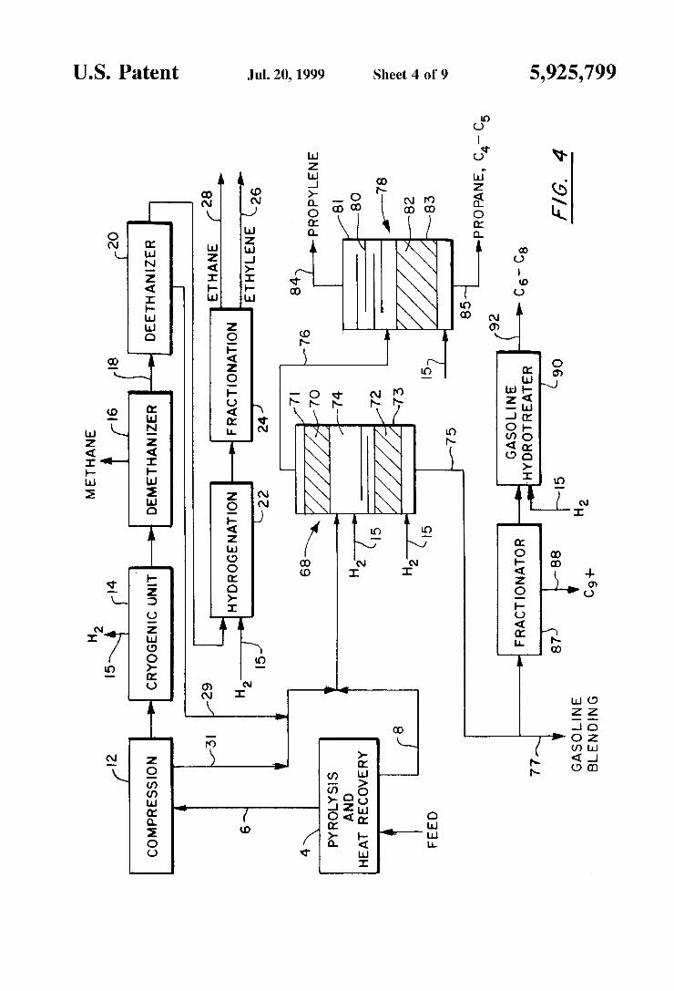
It is possible to eliminate the additional ?Xed bed catalyst reactor as shoWn in FIG. 4. This scheme differs from FIG.
10
15
25
35
45
55
65
6 3 in that toWer 68 noW has hydrogenation catalyst in the stripping section. The toWer 68 has a catalyst bed 70 in the enriching section 71 above the generally centrally located feed Zone 74 and another catalyst bed 72 in the stripping section 73 beloW the feed Zone 74. A tray or packing section is located beloW the feed before catalyst bed 72. Hydrogen streams 15 are fed to the toWer 68 beloW each of the catalyst beds 70 and 72. The distillation conditions of temperature and pressure Within the toWer 68 are maintained such that the C3 to C5 components are distilled overhead and the C6+ are removed as bottoms 75. The MAPD, C4’s and CS’s are mostly hydrogenated in the upper bed 70 With the MAPD being hydrogenated to propylene and the C4 and C5 being hydrogenated to other ole?ns. Since the acetylenes and dienes Will hydrogenate ?rst, there is little or no hydroge nation of the propylene or C4 and C5 ole?ns in this bed 70. Similarly, the C6+ acetylenes and dienes and styrene as Well are hydrogenated primarily to alkenes in the loWer bed 72. The overhead 76 from the toWer 68 containing the C3—C5 unsaturated and saturated components is fed to the toWer 78 containing trays 80 in the enriching section 81 and a catalyst bed 82 in the stripping section 83. The propylene is distilled overhead at 84 and the C4 and C5 unsaturates, mostly ole?ns, are hydrogenated in the bed 82 With the hydrogen stream 15. The propane and the resulting C4 and C5 alkanes are taken out as bottoms 85. The bottoms 75 from the toWer 68, Which noW contains the hydrogenated C6+ components, can be blended directly into gasoline at 77. Alternately, stream 75 can be fractionated at 87 to remove the C9+ components as bottoms 88 and then further hydrotreated at 90 With hydro gen stream 115 to complete the hydrogenation. The product 92 is a saturated C6—C8 heart cut from Which aromatics can be recovered. As can be seen, this embodiment of the invention, Which achieves equivalent separations and reac tions as the FIGS. 1 and 2 processes, substitutes the tWo catalytic distillation hydrogenation units 68 and 78 for the depropaniZer 30, the hydrogenator 34, the fractionator 36, the hydrogenator 46 and the hydrotreater 50, a signi?cant savings in equipment. One of the reasons that hydrogenation in a stripping
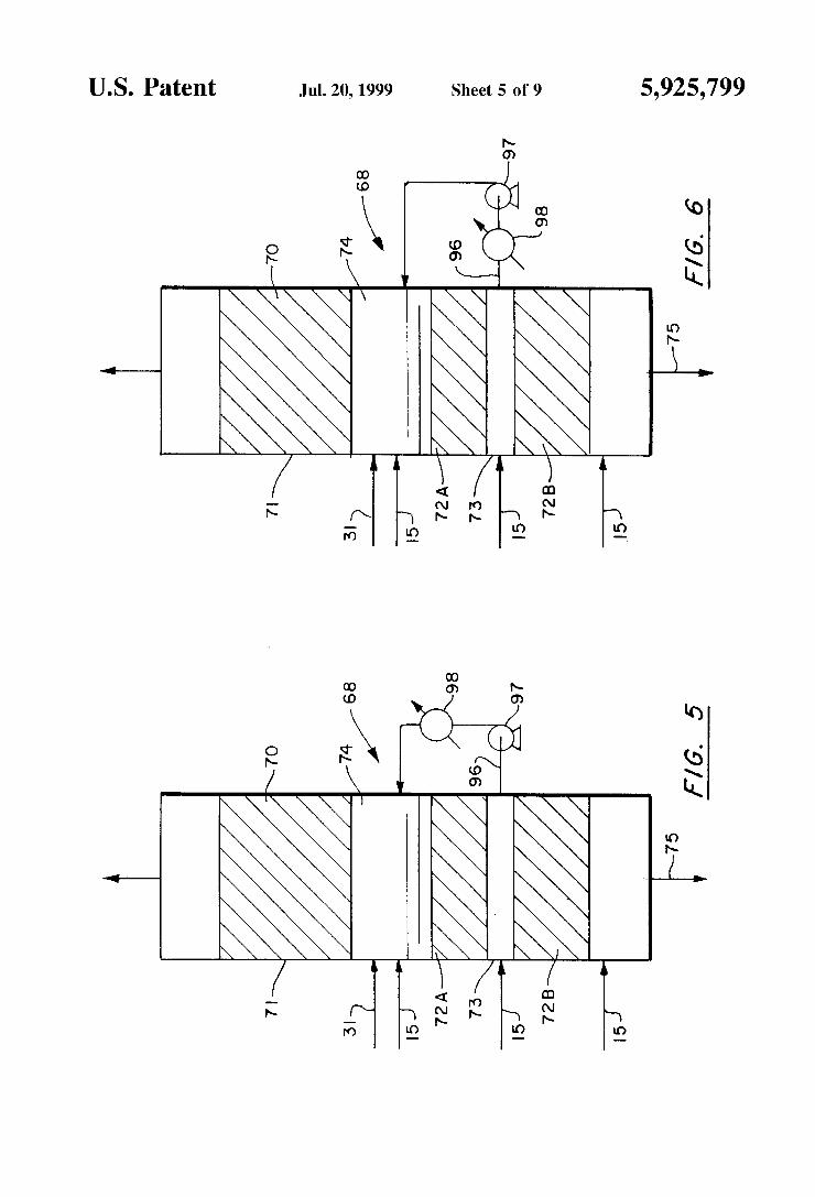
section of a toWer such as toWer 68 has not been employed in the past (such as in the previously mentioned International Application PCT/US94/07758) is the potential for fouling of the catalyst bed such as bed 72. The hydrogenation of C3—C5 acetylenes and dienes has the highest possibility of creating fouling through the formation of long chain oligomers or polymers. In the present invention, the C3—C5 acetylenes and dienes are essentially totally hydrogenated in the enriching section. Therefore, in FIG. 3 it is only ole?ns Which are hydrogenated in the stripping section 83 of toWer 78, thereby reducing considerably the fouling problem. FIG. 5 shoWs an alternate arrangement for the toWer 68 to further alleviate the fouling problem for the arrangement shoWn in FIG. 4. In this arrangement, the bed 72 is split into tWo or even more separate beds 72A and 72B. The bed 72A can be a more selective catalyst in that it Will primarily only support the hydrogenation of the more highly unsaturated compounds. Therefore, at this location in the toWer Where some propy lene may be present, only the acetylenes and dienes are hydrogenated. On the other hand, the catalyst in bed 72B can be more active and non-selective Which Will cause the hydrogenation of all the remaining unsaturates present at that location. As one eXample only, the catalyst in bed 72B may have a higher metal content, such as palladium oXide, than the metal content of the catalyst in bed 72A.
Another technique used in FIG. 5 to prevent the hydro genation of propylene in the upper portion of the stripping
5,925,799 7
section is to pump liquid around in the stripping section. A bottoms side stream 96 is WithdraWn by the pump 97 and cooled at 98 and then injected back into the feed Zone 74 above the stripping section 73. Alternately, in FIG. 6, a vapor stream can be WithdraWn, condensed at 98, and then pumped at 97 back to the top of the catalyst bed. Withdrawing a vapor stream results in a loWer concentration of oligomers and other heavy material being recycled to the top of the catalyst bed. This pump around not only removes heat of reaction and increases the Wetting of the catalyst but it also dilutes the concentration of acetylenes and dienes Which are present and Which Would otherWise tend to cause fouling.
Another factor decreasing the effect of oligomer forma tion in the FIG. 4 scheme is the high concentration of aromatics present in the stripping section. The C6—C9 frac tion from a steam cracker is predominantly aromatics. The concentration of acetylenes and dienes is loW. This is because these compounds cycliZe in the cracking heater coils, forming aromatics. Since aromatic compounds are good solvents, they tend to reduce the rate of fouling. A further variation of the present invention is shoWn in
FIG. 7 Where the catalytic distillation hydrogenation unit 100 contains tWo catalyst beds 102 and 103 in the upper portion above the feed and tWo more catalyst beds 104 and 105 in the loWer portion beloW the feed. A tray section betWeen the feed point and catalyst section 104 is desirable. MAPD, C4’s and CS’s are mostly hydrogenated in the upper portion While the C6+ are mostly hydrogenated in the loWer portion. The overhead 106 from the depentaniZer column 100 containing the C3—C5 components is fed to the depro pyleniZer 108 Where the propylene product is separated from the basically saturated C3—C5 components 112 Which are recycled to the pyrolysis heater. The C6+ bottoms 114 from the depentaniZer 100 can be blended directly into gasoline. In this FIG. 7 embodiment, some of the same techniques are used as in FIG. 3. High re?ux ratios are utiliZed to remove heat of reaction and dilute the concentration of propylene in the liquid phase. The pump around circuit generally desig nated 107 is employed for the same reasons as in FIG. 5. In addition, the enriching section noW also has tWo separate catalyst beds 102 and 103 and employs a pump around circuit 109. In general, catalyst bed 102 Would hydrogenate acetylenes and di-ole?ns and catalyst bed 103 Would hydro genate some or all of the C4—C5 ole?ns. The catalyst in the bed 102 Would be less active and more selective than the catalyst in bed 103. The pump around circuit 109 serves to maintain a high mass ?oW in catalyst bed 102 to regulate temperatures and reactant concentrations and keep the cata lyst highly liquid loaded.
The stripping section also contains tWo catalyst beds With the upper bed 104 more selective than the bottom bed 105. Acetylenes and dienes and styrenes are generally hydroge nated in catalyst bed 104 and ole?ns are generally hydro genated in catalyst bed 105. Product stream (88 and 92) is a loW unsaturate stream suitable for gasoline blending Without further treatment if loW sulfur containing feedstocks are utiliZed in the pyrolysis heaters. This FIG. 7 scheme has higher losses of propylene and greater tendency for catalyst fouling than the process schemes of FIGS. 3 to 6 but the capital cost is loWer as all of the hydrogenation is contained in one toWer.
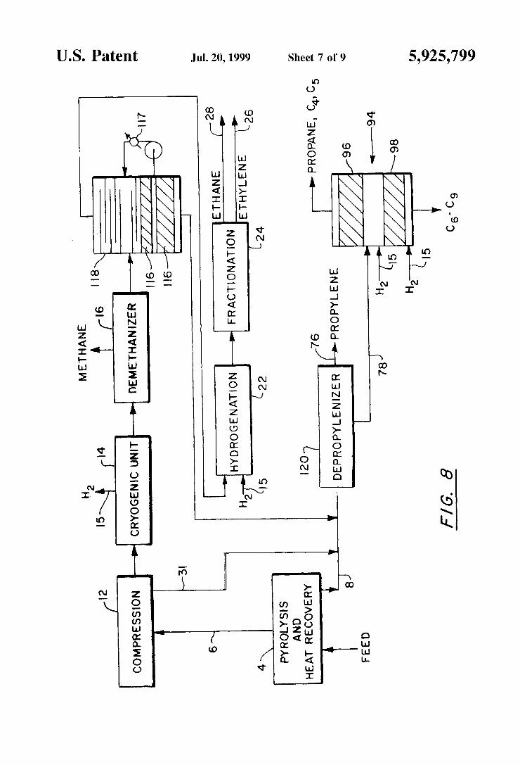
FIG. 8 is a further variation of the invention and involves the use of catalytic distillation hydrogenation in conjunction With the deethaniZer. One or more hydrogenation catalyst beds 116 are placed in the bottom of the deethaniZer column 118. The overhead from the deethaniZer, Which still contains the C2 acetylenes, the ethylene and the ethane, is handled the
10
15
25
35
45
55
65
8 same as in FIGS. 3 to 6. In the catalyst beds 116 in the bottom part of the deethaniZer 118, the C3+ acetylenes and dienes can be totally or at least mostly hydrogenated. Catalyst fouling tendencies are a concern; hoWever they are mitigated by the high concentration of aromatics present. Also, the use of tWo or more catalyst beds and pump around Will minimiZe catalyst fouling tendencies. Fouling of the reboiler is minimiZed as the acetylenes and dienes are hydrogenated before the reboiler. Since hydrogenation is noW taking place in the deethaniZer, the depropyleniZer 120 need not have catalytic distillation and hydrogenation as in the FIGS. 3 to 6 arrangement. The depropyleniZer 120 noW merely involves fractionation to separate the propylene from the bottoms 78. In this scheme, the balance of the hydro genation Which is not completed in the deethaniZer 118 is essentially completed in the depentaniZer 94. As shoWn in this FIG. 8, the deethaniZer 118 could utiliZe a side con denser 117 in the pump around to remove the heat of the hydrogenation reaction, in addition to use of a pump around.
Other process schemes are also possible utiliZing the general principles outlined. For example, in FIG. 9, The hydrocarbon is fed to the toWer 120 Which is noW function ing as a depropyleniZer. The catalytic distillation bed 122 in the enriching section noW has trays 124 above and 126 beloW as Well as the trays 127 in the stripping section. In this catalytic distillation bed 122, MA and PD are hydrogenated, mostly to propylene. The high re?ux ratio required for separation of propylene easily removes the heat of reaction and provides su?icient liquid ?oW for optimum catalyst performance. The bottoms from the column, stream 128, is fed to a depentaniZer 130. The depentaniZer has a catalytic distillation bed in the enriching section and trays 134 in the stripping section. In this catalytic distillation bed 132, all C4—C5 acetylenes, dienes and ole?ns are hydrogenated to C4—C5 alkanes. Ahigh re?ux ratio is utiliZed to remove heat of reaction. The bottoms 136 from the depentaniZer 130 is sent to conventional gasoline hydrogenation. In FIG. 10, the same scheme is utiliZed except that the depentaniZer 130 has a catalytic distillation section in the stripping section and produces a product suitable for gasoline blending. This FIG. 10 also illustrates each catalyst bed being divided into tWo sections. Also, the beds in the enriching section and the beds in the stripping section have each been illustrated as being split into tWo separate sections Which may contain catalysts of different activity. A pump around cooler system 140 around the catalyst bed beloW the feed Will assist in remov ing heat of reaction. What is claimed is: 1. A method of processing a cracked feed stream contain
ing hydrogen, C2 components including ethylene, C3 com ponents including propylene, acetylenes and dienes, C4 and C5 components including acetylenes, dienes and ole?ns and C6+ components including unsaturates to recover said eth ylene and propylene therefrom and to hydrogenate said C3 acetylenes and dienes to produce additional propylene and to hydrogenate at least some of said C4 and C5 acetylenes, dienes and ole?ns to saturates and to hydrogenate said C6+ unsaturates to a mixture of ole?ns and saturates Without signi?cantly hydrogenating said ethylene and propylene comprising the steps of:
a. separating said hydrogen and said C2 components from said feed stream leaving a C3+ stream;
b. separating said ethylene as a product from said sepa rated C2 components;
c. introducing said C3+ stream and a quantity of hydrogen into the feed Zone of a reaction distillation column having an enriching section above said feed Zone and a


