Methylformate from CO2: an Integrated Process Combining Catalytic Hydrogenation and Reactive Distillation Martin Scott,a Christian G. Westhues,a Teresa Kaiser,b Janine C. Baums,a Andreas Jupke,b Giancarlo Franciòa,*, Walter Leitnera,c,*
a Institut für Technische und Makromolekulare Chemie (ITMC), RWTH Aachen University, Worringerweg 2, 52074 Aachen, Germanyb AVT.FVT — Chair of Fluid Process Engineering, RWTH Aachen University, Forckenbeckstraße 51, 52074 Aachen, Germanyc Max Planck Institute for Chemical Energy Conversion, Stiftstraße 34-36, 45470 Mülheim a. d. Ruhr, Germany
1. General Information........................................................................................................................2
1.1 General Methods and Chemicals.............................................................................................21.2 Analytical Methods..................................................................................................................2
2.1 Synthesis of L1, bis(bis(4-octylphenyl)phosphanyl)methane ..................................................22.2 Synthesis of L2, bis(bis(4-dodecylphenyl)phosphanyl)methane .............................................52.3 Synthesis of 1 (2 was prepared following the same procedure using L2 as the ligand) ..........72.4 General Procedure for Catalytic Reactions and Catalyst Recycling .......................................112.5 General Procedure for Hydrogenation Experiments in the Semi-Continuous Operated Reaction Set-Up.................................................................................................................................12
2.5.1 Preparation of the Substrate Solution...........................................................................122.5.2 Preparation of the Catalyst Phase .................................................................................122.5.3 Density Determination of the CO2-saturated Substrate Solution..................................132.5.4 General Procedure for Catalysis and Catalyst Recycling................................................142.5.5 H2-Volume/time Curves.................................................................................................152.5.6 Mass Balance Tables......................................................................................................16
2.6 General Procedure for the Esterification of FA in the presence of Amines...........................172.7 Reactive Distillation of a Model Mixture containing MDEA with a Laboratory Equipment ..202.8 Reactive Distillation of a Model Mixture containing 1,2-DMI at Technical Scale ..................21
1. General Information1.1 General Methods and Chemicals
All procedures using air sensitive compounds were carried out under an inert argon atmosphere (argon 4.8, by Westphal AG). The solvents n-decan (Sigma Aldrich, used as received) and methanol (Sigma Aldrich, purified by distillation) were degassed via a glass frit by bubbling with argon and stored over 4 Å molecular sieves. The amines methyldiethanolamine (MDEA) (Fisher Scientific International, used as received), triethylamine (Sigma Aldrich, purified by distillation) and tripropylamine (Sigma Aldrich, purified by distillation) were degassed by freeze-pump-thaw cycles. The gases hydrogen (4.6, by Air Products) and carbon dioxide (2.6, by Westphal AG) were used without further purification. 1-Bromo-4-n-octylbenzene (acbr GmbH) and bis(dichlorophosphino)methane (acbr GmbH) were used as received. The compounds [Ru(dmso)₄Cl₂][1] and 1-bromo-4-n-dodecylbenzene[2] were synthesized by literature reported procedures. If not indicated otherwise, common solvents where used as received or purified by general purification methods.[3]
1.2 Analytical Methods
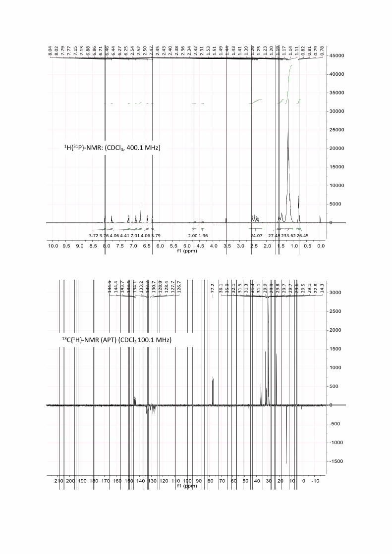
NMR spectra were recorded on an AV-400 or a DPX-300 (Bruker) at 298 K. Chemical shifts are reported in ppm relative to the residual solvent peak of the used deuterated solvent for 1H and 13C NMR.[4] Spin multiplicities are reported as s (singlet) d (doublet), t (triplet). Coupling of higher multiplicities or overlapped signals are given as m (mulitplet).ICP-MS analysis were performed on an ICP-MS triple quadrupole (Agilent, model 8800) by using water (calibration curve) or 1,4-dioxane (standard addition method) as matrices.HRMS EI-MS determinations were carried out at MAT 95 (Thermo Fisher Scientific, former. Finnigan Instrument Corporation) (EI) or on an Exactive™ Plus Orbitrap (Thermo Fisher Scientific).
2. Experimental2.1 Synthesis of L1, bis(bis(4-octylphenyl)phosphanyl)methane
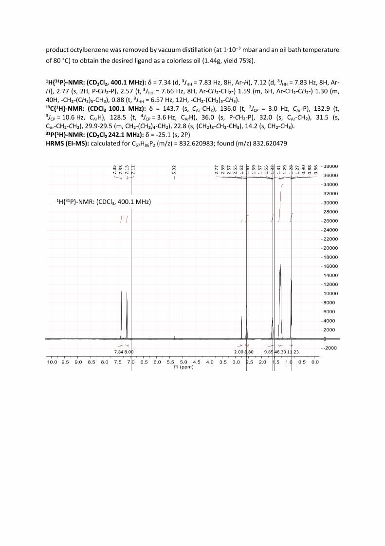
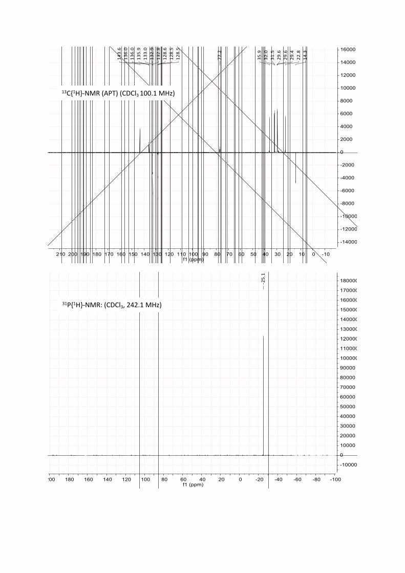
1-Bromo-4-octylbenzene (3.34 g, 12.4 mmol, 5.4 eq) dissolved in THF (10 mL) was added dropwise to magnesium turnings (500 mg, 20.5 mmol, 8.9 eq) suspended in THF (20 ml) and heated to 40 °C. The dropwise additions rate was adapted to maintain a constant reflux and bubble formation at the magnesium turnings. After full addition, the
mixture was stirred for 2 h at 60 °C. Subsequently, the unconverted magnesium was removed via filtration and the solution was cooled to -78 °C, whereby the Grignard-reagent precipitated. To this suspension, a solution of bis(dichlorophosphino)methane (500 mg, 2.3 mmol, 1.0 eq) in THF (5
mL) was added dropwise via a syringe pump. The addition was carried out at 78 °C and the reaction was stirred over 12-16 h while warming up to room temperature. After this time, the reaction progress
was monitored by 31P-NMR, typically showing the desired product as a singlet at 24 to 26 ppm in THF. After full conversion, a degassed solution of NH4Cl (aq) was added to hydrolyze the excess of the Grignard-reagent. The organic layer was separated, dried over MgSO₄ and the solvent was removed in vacuo. The residue was washed with methanol and dried in vacuo. Subsequently, the hydrolysis
product octylbenzene was removed by vacuum distillation (at 1·10⁻³ mbar and an oil bath temperature of 80 °C) to obtain the desired ligand as a colorless oil (1.44g, yield 75%).
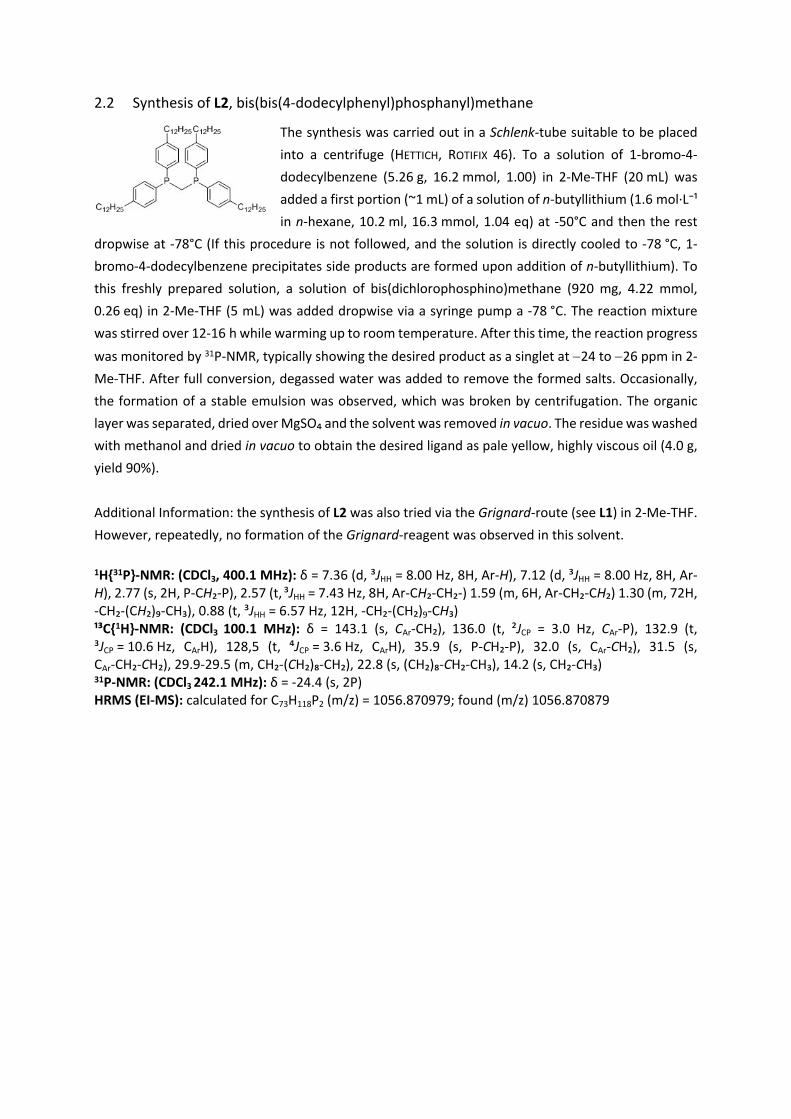
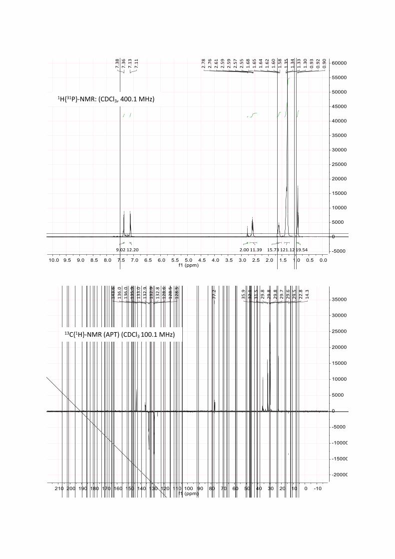
2.2 Synthesis of L2, bis(bis(4-dodecylphenyl)phosphanyl)methane
The synthesis was carried out in a Schlenk-tube suitable to be placed into a centrifuge (HETTICH, ROTIFIX 46). To a solution of 1-bromo-4-dodecylbenzene (5.26 g, 16.2 mmol, 1.00) in 2-Me-THF (20 mL) was added a first portion (~1 mL) of a solution of n-butyllithium (1.6 mol·L⁻¹ in n-hexane, 10.2 ml, 16.3 mmol, 1.04 eq) at -50°C and then the rest
dropwise at -78°C (If this procedure is not followed, and the solution is directly cooled to -78 °C, 1-bromo-4-dodecylbenzene precipitates side products are formed upon addition of n-butyllithium). To this freshly prepared solution, a solution of bis(dichlorophosphino)methane (920 mg, 4.22 mmol, 0.26 eq) in 2-Me-THF (5 mL) was added dropwise via a syringe pump a -78 °C. The reaction mixture was stirred over 12-16 h while warming up to room temperature. After this time, the reaction progress
was monitored by 31P-NMR, typically showing the desired product as a singlet at 24 to 26 ppm in 2-Me-THF. After full conversion, degassed water was added to remove the formed salts. Occasionally, the formation of a stable emulsion was observed, which was broken by centrifugation. The organic layer was separated, dried over MgSO₄ and the solvent was removed in vacuo. The residue was washed with methanol and dried in vacuo to obtain the desired ligand as pale yellow, highly viscous oil (4.0 g, yield 90%).
Additional Information: the synthesis of L2 was also tried via the Grignard-route (see L1) in 2-Me-THF. However, repeatedly, no formation of the Grignard-reagent was observed in this solvent.
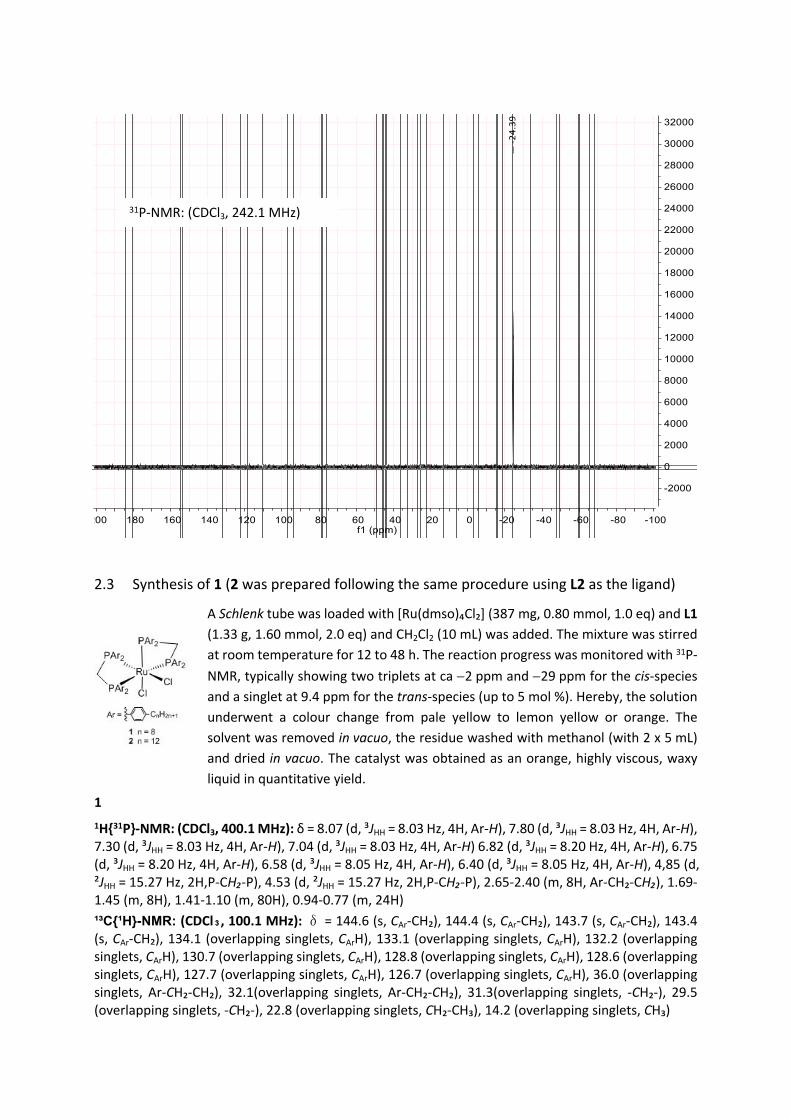
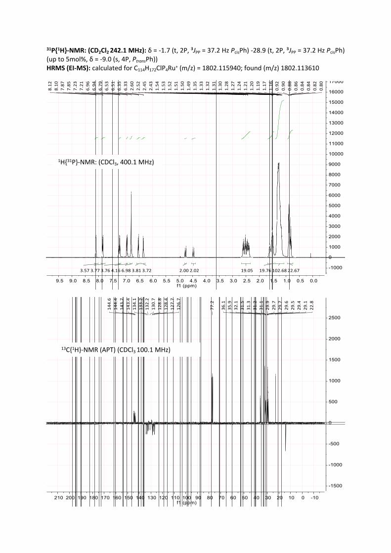
2.3 Synthesis of 1 (2 was prepared following the same procedure using L2 as the ligand)
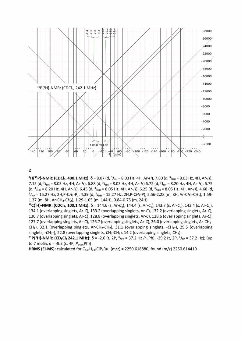
A Schlenk tube was loaded with [Ru(dmso)₄Cl₂] (387 mg, 0.80 mmol, 1.0 eq) and L1 (1.33 g, 1.60 mmol, 2.0 eq) and CH2Cl2 (10 mL) was added. The mixture was stirred at room temperature for 12 to 48 h. The reaction progress was monitored with 31P-NMR, typically showing two triplets at ca 2 ppm and 29 ppm for the cis-species and a singlet at 9.4 ppm for the trans-species (up to 5 mol %). Hereby, the solution underwent a colour change from pale yellow to lemon yellow or orange. The solvent was removed in vacuo, the residue washed with methanol (with 2 x 5 mL) and dried in vacuo. The catalyst was obtained as an orange, highly viscous, waxy liquid in quantitative yield.
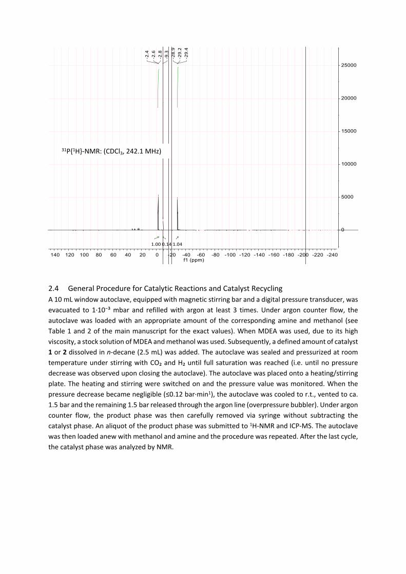
2.4 General Procedure for Catalytic Reactions and Catalyst RecyclingA 10 mL window autoclave, equipped with magnetic stirring bar and a digital pressure transducer, was evacuated to 1·10⁻³ mbar and refilled with argon at least 3 times. Under argon counter flow, the autoclave was loaded with an appropriate amount of the corresponding amine and methanol (see Table 1 and 2 of the main manuscript for the exact values). When MDEA was used, due to its high viscosity, a stock solution of MDEA and methanol was used. Subsequently, a defined amount of catalyst 1 or 2 dissolved in n-decane (2.5 mL) was added. The autoclave was sealed and pressurized at room temperature under stirring with CO₂ and H₂ until full saturation was reached (i.e. until no pressure decrease was observed upon closing the autoclave). The autoclave was placed onto a heating/stirring plate. The heating and stirring were switched on and the pressure value was monitored. When the pressure decrease became negligible (≤0.12 bar·min1), the autoclave was cooled to r.t., vented to ca. 1.5 bar and the remaining 1.5 bar released through the argon line (overpressure bubbler). Under argon counter flow, the product phase was then carefully removed via syringe without subtracting the catalyst phase. An aliquot of the product phase was submitted to 1H-NMR and ICP-MS. The autoclave was then loaded anew with methanol and amine and the procedure was repeated. After the last cycle, the catalyst phase was analyzed by NMR.
31P{1H}-NMR: (CDCl3, 242.1 MHz)
2.5 General Procedure for Hydrogenation Experiments in the Semi-Continuous Operated Reaction Set-Up
2.5.1 Preparation of the Substrate SolutionA 900 mL high pressure reservoir was filled with methanol (178.5 mL, 4.4 mol), n-decane (88.3 mL, 10.3 mol% with respect to methanol) and
1,2-DMI (278.8 g, 2.9 mol). The reservoir was then pressurized with CO2 (35 bar) at r.t. until full saturation reached i.e. until no CO2 flow was detected by the mass flow meter (MFM). The high pressure reservoir was then heated to reaction temperature (65 °C).
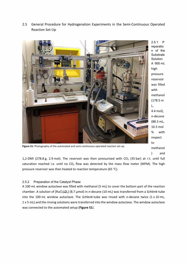
2.5.2 Preparation of the Catalyst PhaseA 100 mL window autoclave was filled with methanol (5 mL) to cover the bottom part of the reaction chamber. A solution of [RuCl2L22] (8.7 µmol) in n-decane (10 mL) was transferred from a Schlenk-tube into the 100 mL window autoclave. The Schlenk-tube was rinsed with n-decane twice (1 x 10 mL, 1 x 5 mL) and the rinsing solutions were transferred into the window autoclave. The window autoclave was connected to the automated setup (Figure S1).
Figure S1: Photography of the automated and semi-continuous operated reaction set-up.
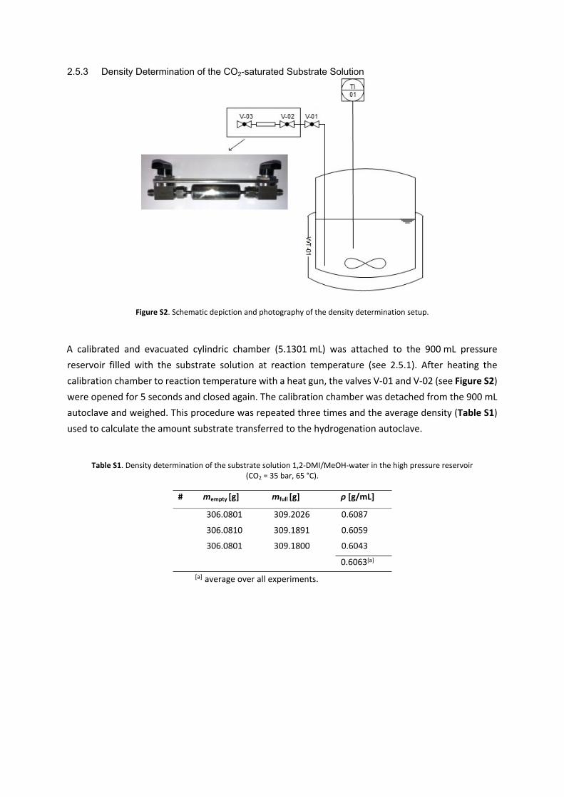
2.5.3 Density Determination of the CO2-saturated Substrate Solution
Figure S2. Schematic depiction and photography of the density determination setup.
A calibrated and evacuated cylindric chamber (5.1301 mL) was attached to the 900 mL pressure reservoir filled with the substrate solution at reaction temperature (see 2.5.1). After heating the calibration chamber to reaction temperature with a heat gun, the valves V-01 and V-02 (see Figure S2) were opened for 5 seconds and closed again. The calibration chamber was detached from the 900 mL autoclave and weighed. This procedure was repeated three times and the average density (Table S1) used to calculate the amount substrate transferred to the hydrogenation autoclave.
Table S1. Density determination of the substrate solution 1,2-DMI/MeOH-water in the high pressure reservoir (CO2 = 35 bar, 65 °C).
# mempty [g] mfull [g] ρ [g/mL]
1 306.0801 309.2026 0.6087
2 306.0810 309.1891 0.6059
3 306.0801 309.1800 0.6043
4 0.6063[a]
[a] average over all experiments.
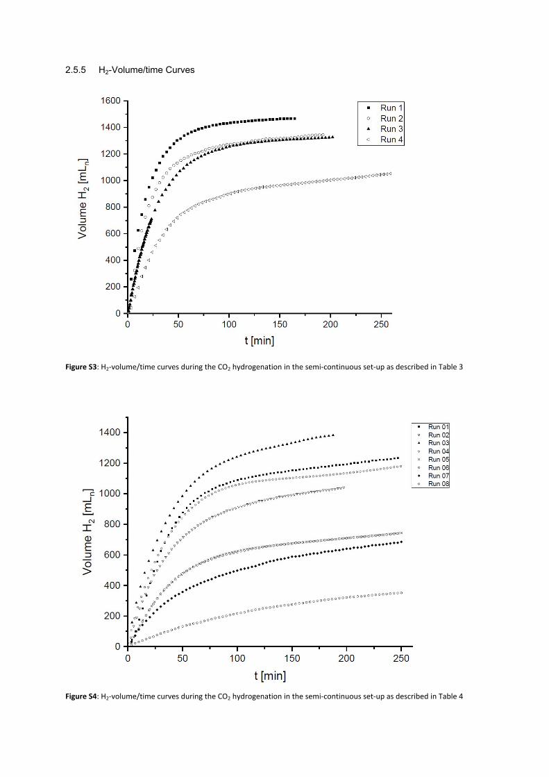
2.5.4 General Procedure for Catalysis and Catalyst RecyclingIn the first run, an aliquot of the CO2-presaturated methanolic amine solution (~30 g) was transferred via a HPLC pump into the 100 mL window autoclave containing the catalyst solution (see 2.5.2). The autoclave was pressurized with hydrogen until a total pressure of 135 bar was reached. The stirrer was switched on (700 rpm) and the pressure during the reaction was maintained constant as the hydrogen consumption is compensated by delivering additional H2 via a mass flow controller. As soon as no significant hydrogen consumption (H2 flow ≤0.12 mLn·min-1) was detected (see Figures S3 and S4), the autoclave was cooled to ~15 °C and the product phase was carefully released from the bottom valve. A new aliquot of the presaturated CO2-substrate solution was transferred into the hydrogenation reactor until 135 bar total pressure was reached in the autoclave and the next cycle was started. After each run, a sample of the product phase was submitted to 1H-NMR and ICP-MS. After the last cycle, the catalyst phase was analyzed by NMR.
2.5.5 H2-Volume/time Curves
Figure S3: H2-volume/time curves during the CO2 hydrogenation in the semi-continuous set-up as described in Table 3
Figure S4: H2-volume/time curves during the CO2 hydrogenation in the semi-continuous set-up as described in Table 4
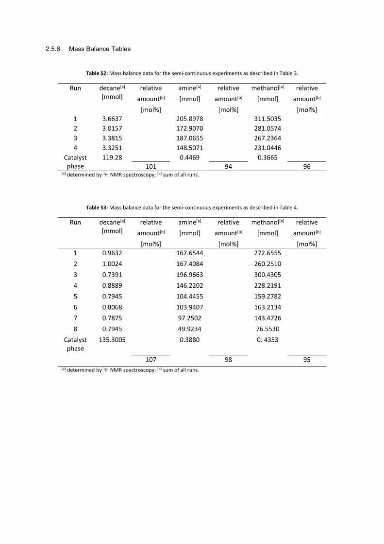
2.5.6 Mass Balance Tables
Table S2: Mass balance data for the semi-continuous experiments as described in Table 3.
95[a] determined by 1H NMR spectroscopy; [b] sum of all runs.
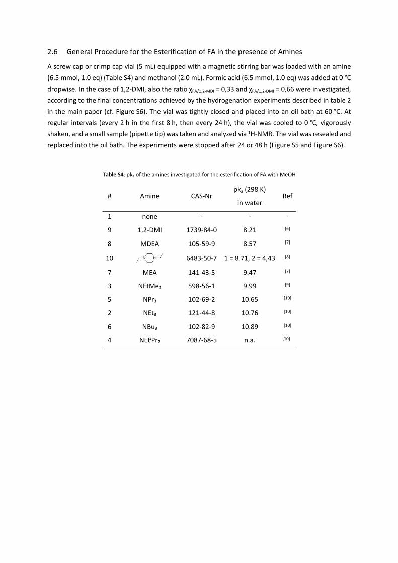
2.6 General Procedure for the Esterification of FA in the presence of Amines
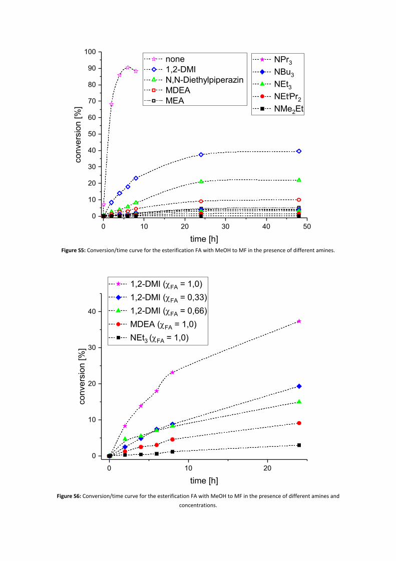
A screw cap or crimp cap vial (5 mL) equipped with a magnetic stirring bar was loaded with an amine (6.5 mmol, 1.0 eq) (Table S4) and methanol (2.0 mL). Formic acid (6.5 mmol, 1.0 eq) was added at 0 °C dropwise. In the case of 1,2-DMI, also the ratio χFA/1,2-MDI = 0,33 and χFA/1,2-DMI = 0,66 were investigated, according to the final concentrations achieved by the hydrogenation experiments described in table 2 in the main paper (cf. Figure S6). The vial was tightly closed and placed into an oil bath at 60 °C. At regular intervals (every 2 h in the first 8 h, then every 24 h), the vial was cooled to 0 °C, vigorously shaken, and a small sample (pipette tip) was taken and analyzed via 1H-NMR. The vial was resealed and replaced into the oil bath. The experiments were stopped after 24 or 48 h (Figure S5 and Figure S6).
Table S4: pka of the amines investigated for the esterification of FA with MeOH
# Amine CAS-Nrpka (298 K)
in waterRef
1 none - - -
9 1,2-DMI 1739-84-0 8.21 [6]
8 MDEA 105-59-9 8.57 [7]
10 6483-50-7 1 = 8.71, 2 = 4,43 [8]
7 MEA 141-43-5 9.47 [7]
3 NEtMe₂ 598-56-1 9.99 [9]
5 NPr₃ 102-69-2 10.65 [10]
2 NEt₃ 121-44-8 10.76 [10]
6 NBu₃ 102-82-9 10.89 [10]
4 NEtiPr₂ 7087-68-5 n.a. [10]
0 10 20 30 40 500
10
20
30
40
50
60
70
80
90
100 NPr3
NBu3
NEt3 NEtiPr2
NMe2Et
conv
ersi
on [%
]
time [h]
none 1,2-DMI N,N-Diethylpiperazin MDEA MEA
Figure S5: Conversion/time curve for the esterification FA with MeOH to MF in the presence of different amines.
Figure S6: Conversion/time curve for the esterification FA with MeOH to MF in the presence of different amines and concentrations.
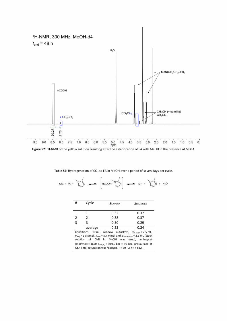
Figure S7: 1H-NMR of the yellow solution resulting after the esterification of FA with MeOH in the presence of MDEA.
Table S5: Hydrogenation of CO₂ to FA in MeOH over a period of seven days per cycle.
# Cycle χFA/Amin χMF/amine
1 1 0.32 0.37 2 2 0.38 0.37 3 3 0.30 0.29
average 0.33 0.34Conditions: 10 mL window autoclave, Vn-decan = 2.5 mL, n[Ru] = 3,5 µmol, nDMI ≈ 5,7 mmol and VMeOH/DMI ≈ 2.5 mL (stock solution of DMI in MeOH was used), amine/cat (mol/mol) ≈ 1650 pCO₂/H₂ = 30/60 bar = 90 bar, pressurized at r.t. till full saturation was reached, T = 60 °C; t = 7 days.
HCO2CH3
H2O
HCOOH
MeN(CH2CH2OH)2
HCO2CH3
CH3OH (+ satellite)CD3OD
1H-NMR, 300 MHz, MeOH-d4tend = 48 h
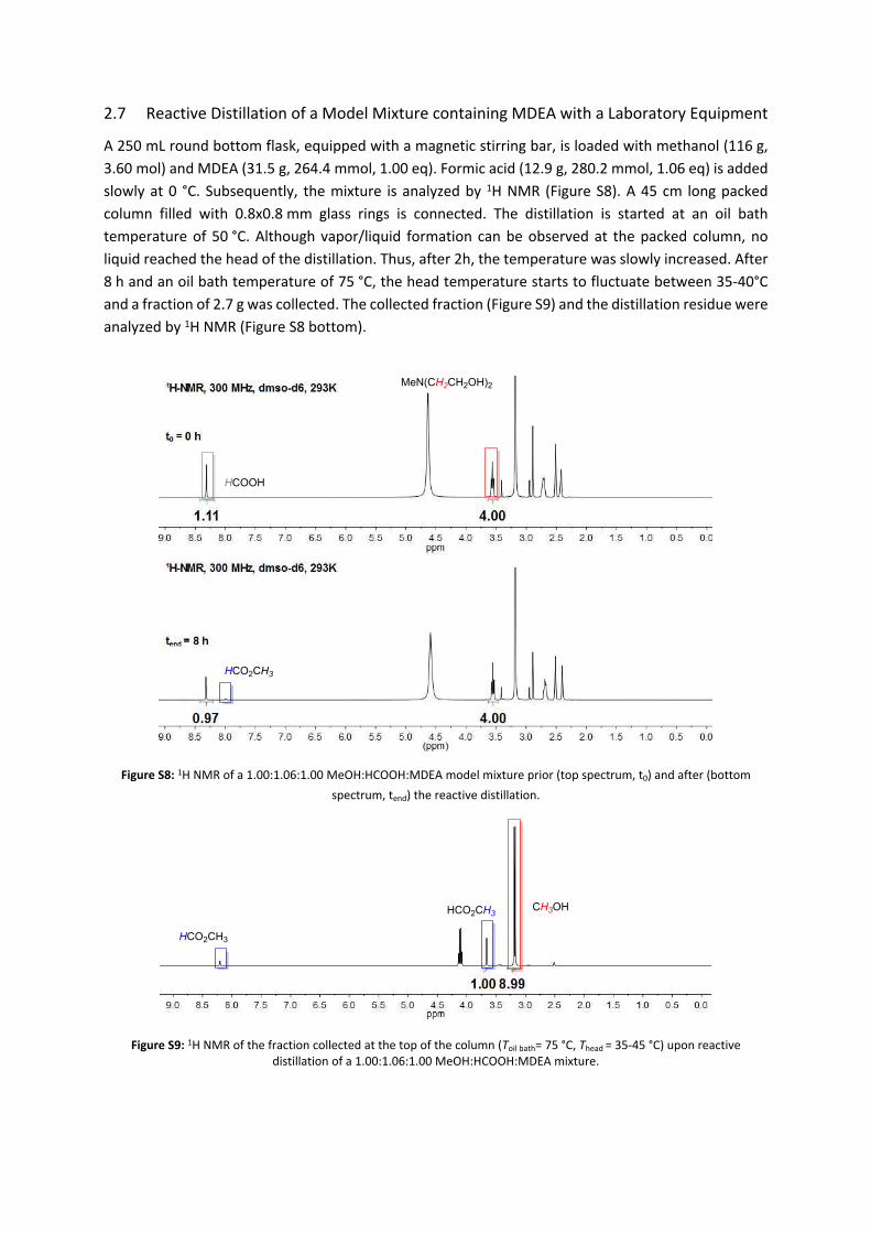
2.7 Reactive Distillation of a Model Mixture containing MDEA with a Laboratory Equipment
A 250 mL round bottom flask, equipped with a magnetic stirring bar, is loaded with methanol (116 g, 3.60 mol) and MDEA (31.5 g, 264.4 mmol, 1.00 eq). Formic acid (12.9 g, 280.2 mmol, 1.06 eq) is added slowly at 0 °C. Subsequently, the mixture is analyzed by 1H NMR (Figure S8). A 45 cm long packed column filled with 0.8x0.8 mm glass rings is connected. The distillation is started at an oil bath temperature of 50 °C. Although vapor/liquid formation can be observed at the packed column, no liquid reached the head of the distillation. Thus, after 2h, the temperature was slowly increased. After 8 h and an oil bath temperature of 75 °C, the head temperature starts to fluctuate between 35-40°C and a fraction of 2.7 g was collected. The collected fraction (Figure S9) and the distillation residue were analyzed by 1H NMR (Figure S8 bottom).
Figure S8: 1H NMR of a 1.00:1.06:1.00 MeOH:HCOOH:MDEA model mixture prior (top spectrum, t0) and after (bottom spectrum, tend) the reactive distillation.
Figure S9: 1H NMR of the fraction collected at the top of the column (Toil bath= 75 °C, Thead = 35-45 °C) upon reactive distillation of a 1.00:1.06:1.00 MeOH:HCOOH:MDEA mixture.
CH3OHHCO2CH3
HCO2CH3
HCOOH
MeN(CH2CH2OH)2
HCO2CH3
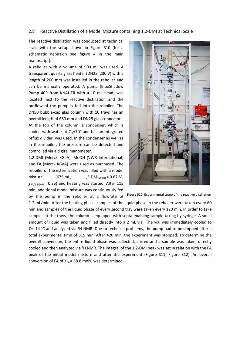
2.8 Reactive Distillation of a Model Mixture containing 1,2-DMI at Technical Scale
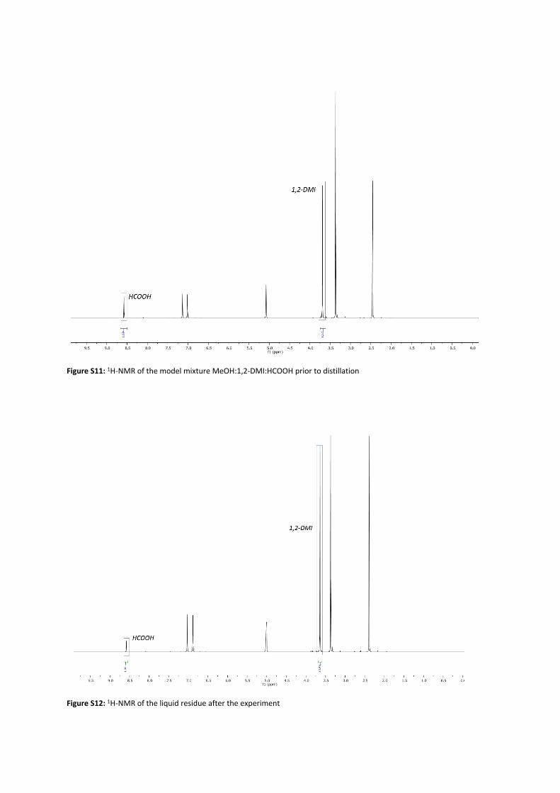
The reactive distillation was conducted at technical scale with the setup shown in Figure S10 (for a schematic depiction see figure 4 in the main manuscript). A reboiler with a volume of 900 mL was used. A transparent quartz glass heater (DN25, 230 V) with a length of 200 mm was installed in the reboiler and can be manually operated. A pump (BlueShadow Pump 40P from KNAUER with a 10 mL head) was located next to the reactive distillation and the outflow of the pump is fed into the reboiler. The DN50 bubble-cap glas column with 10 trays has an overall length of 680 mm and DN25 glas connectors. At the top of the column, a condenser, which is cooled with water at Tin=7°C and has an integrated reflux divider, was used. In the condenser as well as in the reboiler, the pressure can be detected and controlled via a digital manometer.1,2-DMI (Merck KGaA), MeOH (VWR International) and FA (Merck KGaA) were used as purchased. The reboiler of the esterification was filled with a model mixture (675 mL, 1,2-DMIMeOH = 0.67 M, χFA/1,2-DMI = 0.35) and heating was started. After 115 min, additional model mixture was continuously fed by the pump in the reboiler at a flowrate of 1-2 mL/min. After the heating phase, samples of the liquid phase in the reboiler were taken every 60 min and samples of the liquid phase of every second tray were taken every 120 min. In order to take samples at the trays, the column is equipped with septa enabling sample taking by syringe. A small amount of liquid was taken and filled directly into a 2 mL vial. The vial was immediately cooled to T=14 °C and analyzed via 1H-NMR. Due to technical problems, the pump had to be stopped after a total experimental time of 315 min. After 420 min, the experiment was stopped. To determine the overall conversion, the entire liquid phase was collected, stirred and a sample was taken, directly cooled and then analyzed via 1H NMR. The integral of the 1,2-DMI peak was set in relation with the FA peak of the initial model mixture and after the experiment (Figure S11, Figure S12). An overall conversion of FA of XFA = 58.8 mol% was determined.
Figure S10: Experimental setup of the reactive distillation
Figure S11: 1H-NMR of the model mixture MeOH:1,2-DMI:HCOOH prior to distillation
Figure S12: 1H-NMR of the liquid residue after the experiment
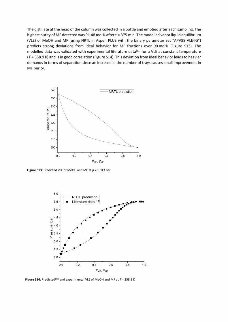
The distillate at the head of the column was collected in a bottle and emptied after each sampling. The highest purity of MF detected was 91.48 mol% after t = 375 min. The modelled vapor liquid equilibrium (VLE) of MeOH and MF (using NRTL in Aspen PLUS with the binary parameter set “APV88 VLE-IG”) predicts strong deviations from ideal behavior for MF fractions over 90 mol% (Figure S13). The modelled data was validated with experimental literature data[11] for a VLE at constant temperature (T = 358.9 K) and is in good correlation (Figure S14). This deviation from ideal behavior leads to heavier demands in terms of separation since an increase in the number of trays causes small improvement in MF purity.
Figure S13: Predicted VLE of MeOH and MF at p = 1.013 bar
Figure S14: Predicted[11] and experimental VLE of MeOH and MF at T = 358.9 K
Table S6: Properties of pure components present in the reaction mixtures for the esterification step.[12]
3. References[1] a) I. P. Evans, A. Spencer, G. Wilkinson, J. Chem. Soc., Dalton Trans. 1973; b) E. Alessio, G.
Mestroni, G. Nardin, W. M. Attia, M. Calligaris, G. Sava, S. Zorzet, Inorg. Chem. 1988, 27, 4099-4106.
[2] Q. Wang, L. Wang, L. Yu, J. Am. Chem. Soc. 1998, 120, 12860-12868.[3] W. L. F. Armarego, C. Chai, Purification of Laboratory Chemicals, Elsevier Science, 2009.[4] G. R. Fulmer, A. J. M. Miller, N. H. Sherden, H. E. Gottlieb, A. Nudelman, B. M. Stoltz, J. E.
Bercaw, K. I. Goldberg, Organometallics 2010, 29, 2176-2179.[5] D. Zhu, P. H. M. Budzelaar, Organometallics 2010, 29, 5759-5761.[6] a) O. Jogunola, T. Salmi, J.-P. Mikkola, J. Mol. Liq. 2014, 196, 334-339; b) B. Lenarcik, P.
Ojczenasz, J. Heterocycl. Chem. 2002, 39, 287-290.[7] A. Tagiuri, M. Mohamedali, A. Henni, J. Chem. Eng. Data 2015, 61, 247-254.[8] N. G. Lamson, G. Cusimano, K. Suri, A. Zhang, K. A. Whitehead, Mol. Pharm. 2016, 13, 578-585.[9] I. Juranić, Croat. Chem. Acta 2014, 87, 343-347.[10] K. Eller, E. Henkes, R. Rossbacher, H. Höke, in Ullmann's Encyclopedia of Industrial Chemistry,
2000.[11] a) J. Zeng, C. Fu, W. Hu, in Tianranqi Huagong. 2000, 25, 3; 54; b) A. T. Sundberg, P. Uusi-Kyyny,
M. Pakkanen, V. Alopaeus, J. Chem. Eng. Data 2011, 56, 2634-2640.[12] CRC Handbook of Chemistry and Physics, 99th Edition, John Rumble, CRC Press, ISBN