Catalytic Membrane Reactors Catalytic Membrane Reactors involving involving Inorganic Inorganic Membranes Membranes - - A short A short overview overview - - Anne JULBE Anne JULBE CNRS Senior Research Scientist CNRS Senior Research Scientist Institut Européen des Membranes (UMR CNRS 5635)- UM 2– CC047 Place Eugène Bataillon – 34095 Montpellier cedex 5 – FRANCE Vrnjačka Banja- Serbia- October 7-12, 2007
Various types of membrane/catalystarrangements in membrane reactorsVariousVarious types of membrane/types of membrane/catalystcatalystarrangements in membrane arrangements in membrane reactorsreactors
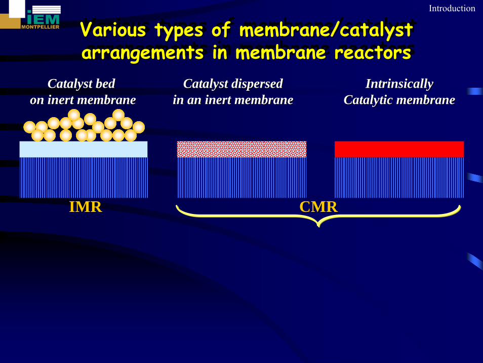
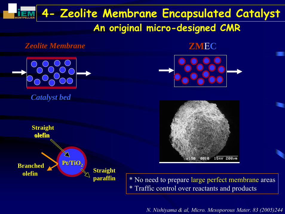
CatalystCatalyst disperseddispersedin an in an inertinert membrane membrane
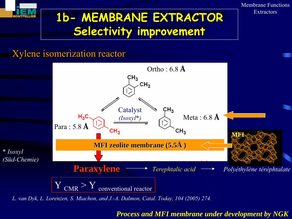
L. van Dyk, L. Lorenzen, S. Miachon, and J.-A. Dalmon, Catal. Today, 104 (2005) 274.
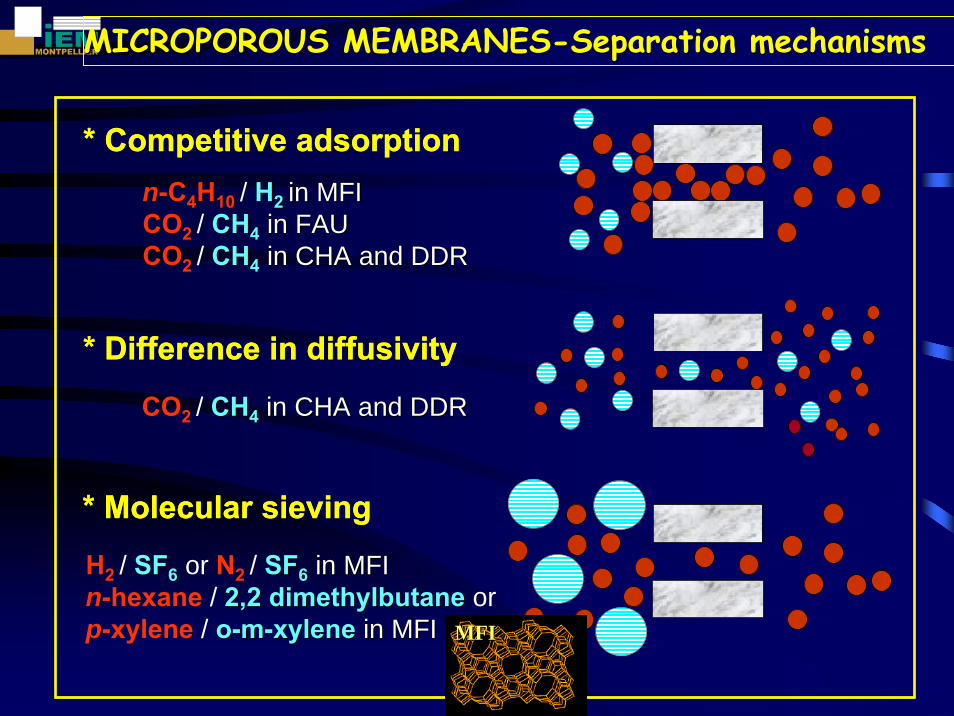
MFIMFI
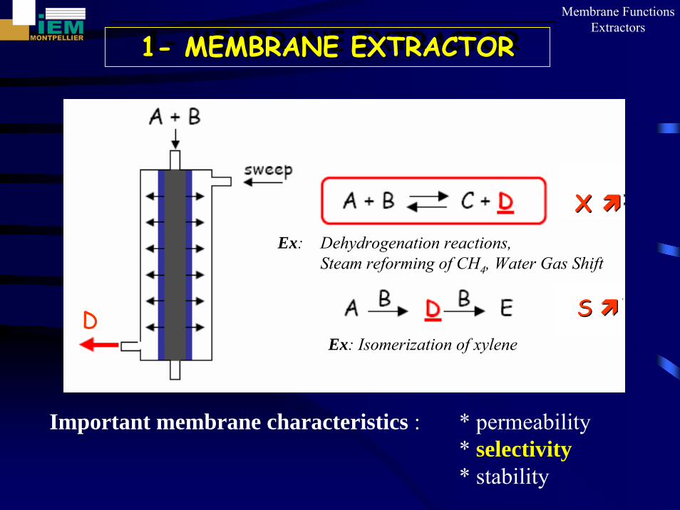
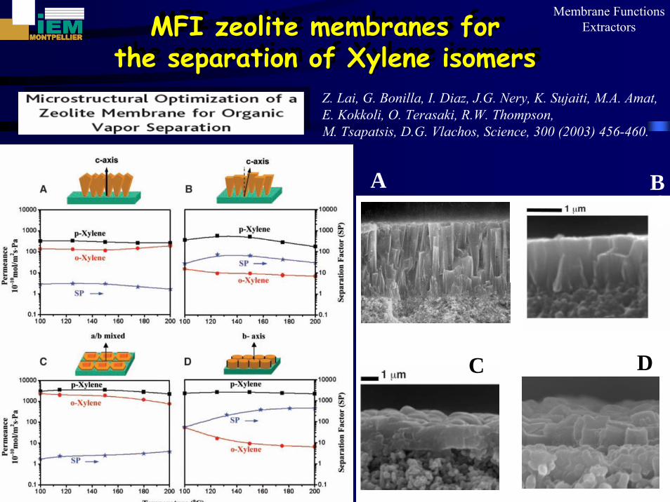
A B
C D
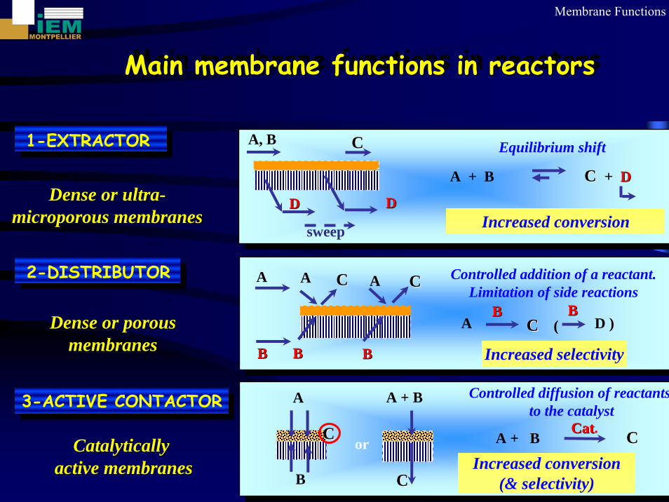
Membrane FunctionsExtractorsMFI zeolite membranes for
the separation of Xylene isomersMFI zeolite membranes forMFI zeolite membranes for
thethe separationseparation ofof XyleneXylene isomersisomersZ. Lai, G. Bonilla, I. Diaz, J.G. Nery, K. Sujaiti, M.A. Amat, E. Kokkoli, O. Terasaki, R.W. Thompson, M. Tsapatsis, D.G. Vlachos, Science, 300 (2003) 456-460.
22-- MEMBRANE DISTRIBUTORMEMBRANE DISTRIBUTOR
Rea
ctio
nzo
ne
A
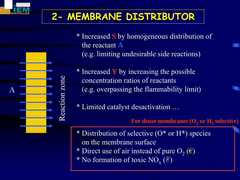
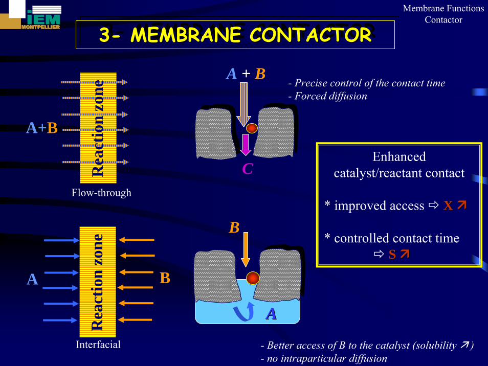
* Increased S by homogeneous distribution of the reactant A(e.g. limiting undesirable side reactions)
* Increased Y by increasing the possible concentration ratios of reactants(e.g. overpassing the flammability limit)
* Limited catalyst desactivation …
* Distribution of selective (O* or H*) specieson the membrane surface
* Direct use of air instead of pure O2 (€)* No formation of toxic NOx ( )
For dense membranes (O2 or H2 selective)
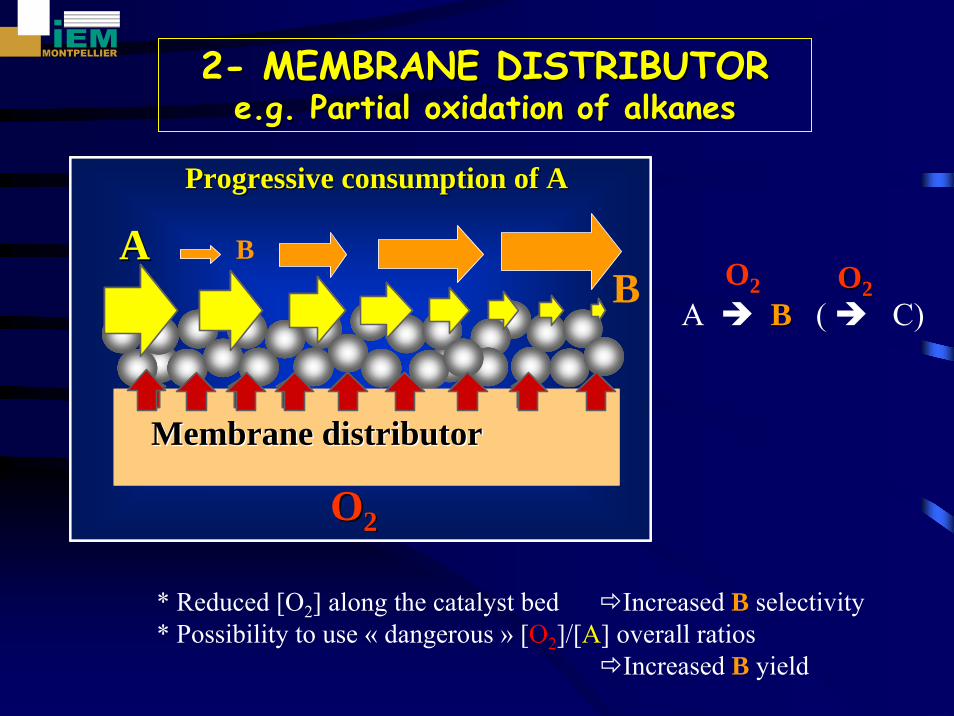
22-- MEMBRANE DISTRIBUTORMEMBRANE DISTRIBUTORe.g. Partial e.g. Partial oxidationoxidation of of alkanesalkanes
O2 OO22
* Reduced [O2] along the catalyst bed Increased B selectivity* Possibility to use « dangerous » [O2]/[A] overall ratios
Increased B yield
AA
OO22
Progressive Progressive consumption consumption of Aof A
Membrane Membrane distributordistributor
AA
OO22
Progressive Progressive consumption consumption of Aof A
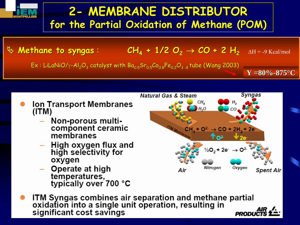
MethaneMethane to to syngassyngas :: CHCH44 + 1/2 O+ 1/2 O22 →→ COCO + 2 H+ 2 H22
Ex : Ex : LiLaNiO/LiLaNiO/γγ--AlAl22OO33 catalyst with Bacatalyst with Ba0.50.5SrSr0.50.5CoCo0.80.8FeFe0.20.2OO3 3 --δδ tube (Wang 2003)tube (Wang 2003)Y =80%Y =80%--875875°°CC
22-- MEMBRANE DISTRIBUTORMEMBRANE DISTRIBUTORfor the Partial for the Partial OxidationOxidation of of MethaneMethane (POM)(POM)
∆H = -9 Kcal/mol
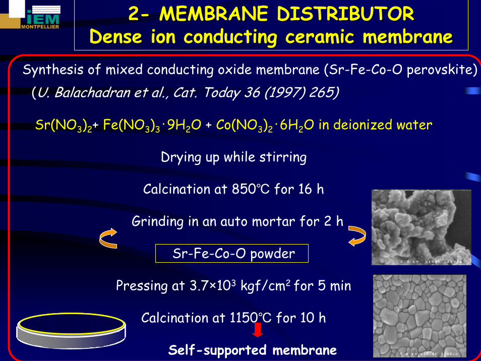
Synthesis of mixed conducting oxide membrane (Sr-Fe-Co-O perovskite)(U. Balachadran et al., Cat. Today 36 (1997) 265)
Sr(NO3)2+ Fe(NO3)3・9H2O + Co(NO3)2・6H2O in deionized water
Drying up while stirring
Calcination at 850℃ for 16 h
Grinding in an auto mortar for 2 h
Sr-Fe-Co-O powder
Pressing at 3.7×10³ kgf/cm2 for 5 min
Calcination at 1150℃ for 10 h
Self-supported membrane
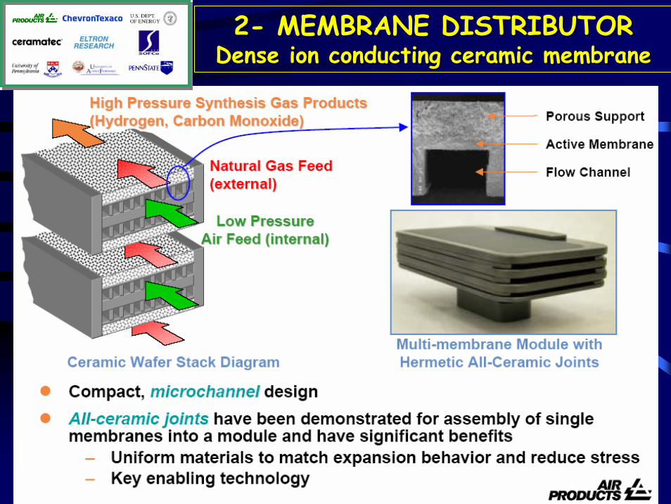
22-- MEMBRANE DISTRIBUTORMEMBRANE DISTRIBUTORDense ion Dense ion conductingconducting ceramicceramic membranemembrane
22-- MEMBRANE DISTRIBUTORMEMBRANE DISTRIBUTORDense ion Dense ion conductingconducting ceramicceramic membranemembrane
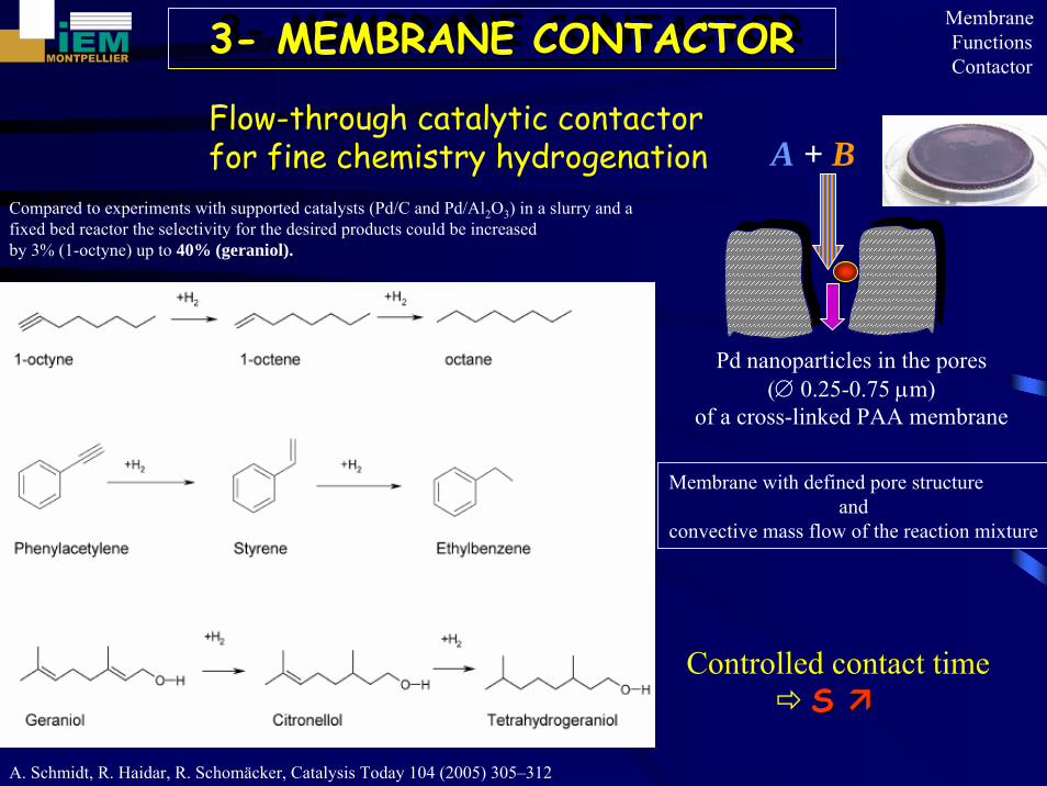
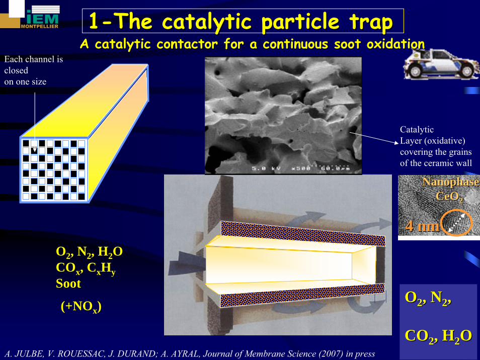
Flow-through catalytic contactorfor fine chemistry hydrogenation
Controlled contact timeS S
A. Schmidt, R. Haidar, R. Schomäcker, Catalysis Today 104 (2005) 305–312
Compared to experiments with supported catalysts (Pd/C and Pd/Al2O3) in a slurry and a fixed bed reactor the selectivity for the desired products could be increasedby 3% (1-octyne) up to 40% (geraniol).
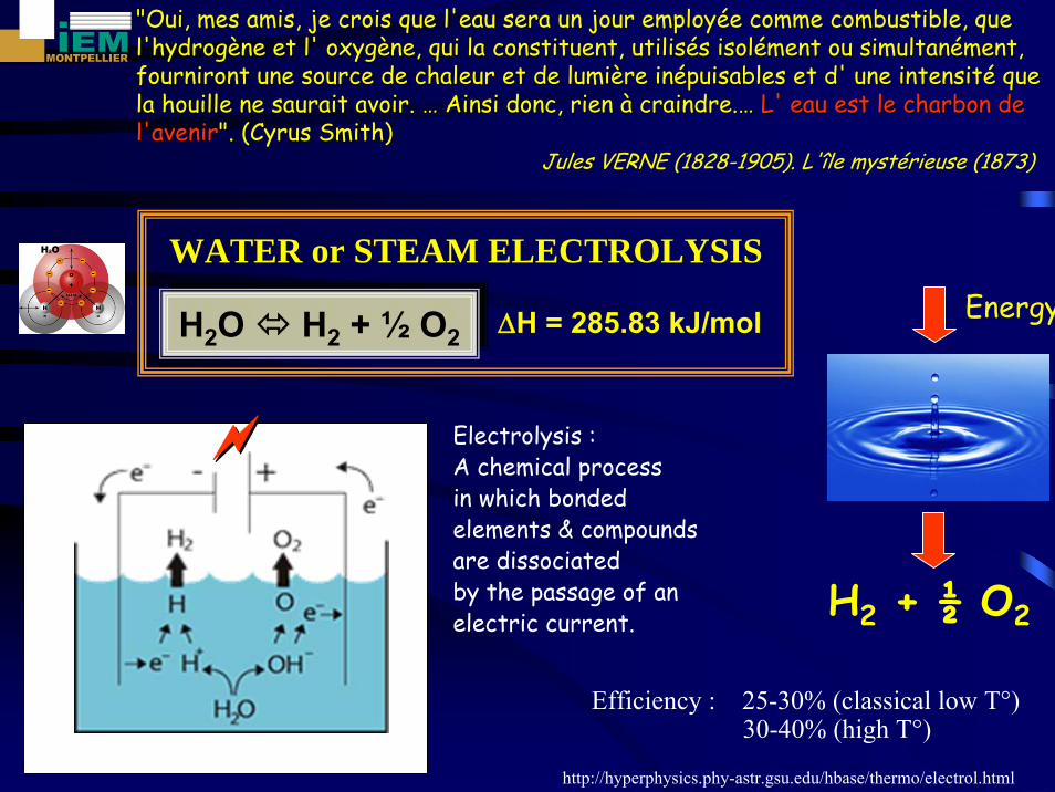
"Oui, mes amis, je crois que l'eau sera un jour employ"Oui, mes amis, je crois que l'eau sera un jour employéée comme combustible, que e comme combustible, que l'hydrogl'hydrogèène et l' oxygne et l' oxygèène, qui la constituent, utilisne, qui la constituent, utiliséés isols isoléément ou simultanment ou simultanéément, ment, fourniront une source de chaleur et de lumifourniront une source de chaleur et de lumièère inre inéépuisables et d' une intensitpuisables et d' une intensitéé que que la houille ne saurait avoir. la houille ne saurait avoir. …… Ainsi donc, rien Ainsi donc, rien àà craindre.craindre.…… L' eau est le charbon de L' eau est le charbon de l'avenirl'avenir". (Cyrus Smith)". (Cyrus Smith)
Electrolysis :A chemical process in which bonded elements & compoundsare dissociated by the passage of an electric current.
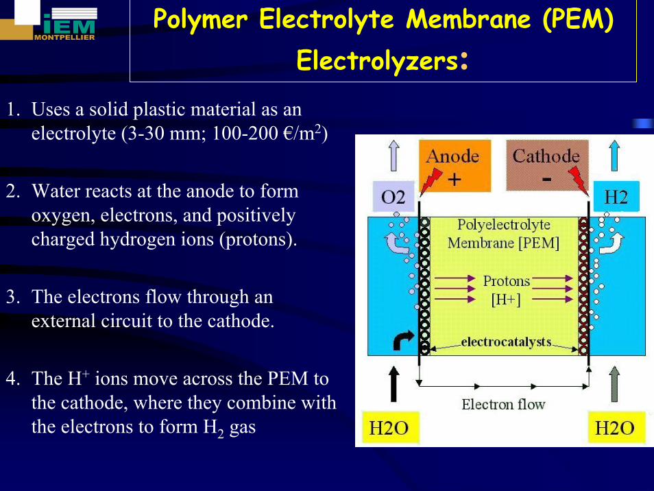
Polymer Electrolyte Membrane (PEM) Electrolyzers:
1. Uses a solid plastic material as an electrolyte (3-30 mm; 100-200 €/m2)
2. Water reacts at the anode to form oxygen, electrons, and positively charged hydrogen ions (protons).
3. The electrons flow through an external circuit to the cathode.
4. The H+ ions move across the PEM to the cathode, where they combine with the electrons to form H2 gas
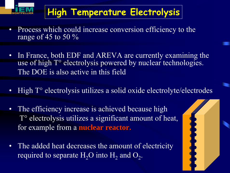
• Process which could increase conversion efficiency to the range of 45 to 50 %
• In France, both EDF and AREVA are currently examining the use of high T° electrolysis powered by nuclear technologies. The DOE is also active in this field
• High T° electrolysis utilizes a solid oxide electrolyte/electrodes
• The efficiency increase is achieved because highT° electrolysis utilizes a significant amount of heat, for example from a nuclear reactor.nuclear reactor.
• The added heat decreases the amount of electricity required to separate H2O into H2 and O2.
High Temperature Electrolysis
H2O H2
e-
e-
I
Circuit externe
O2
Anode 2O2- → O2+ 4 e-
Cathode 2H2O+ 4 e- → 2H2 +2O2-
e-
e- H2O
H2
I
O2
Circuit externe
Cathode 4 H++ 4 e- → 2H2
Anode 2H2
O→ O2+ 4 e- + 4H+
H2O H2
e-
e-
I
Circuit externe
O2
Anode 2O2- → O2+ 4 e-
Cathode 2H2O+ 4 e- → 2H2 +2O2-
e-
e- H2O
H2
I
O2
Circuit externe
Cathode 4 H++ 4 e- → 2H2
Anode 2H2
O→ O2+ 4 e- + 4H+
H2O H2
e-
e-
I
Circuit externe
O2
Anode 2O2- → O2+ 4 e-
Cathode 2H2O+ 4 e- → 2H2 +2O2-
e-
e- H2O
H2
I
O2
Circuit externe
Cathode 4 H++ 4 e- → 2H2
Anode 2H2
O→ O2+ 4 e- + 4H+
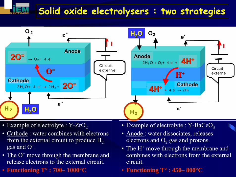
Solid oxide Solid oxide electrolyserselectrolysers : two strategies: two strategies
• Example of electrolyte : Y-ZrO2• Cathode : water combines with electrons
from the external circuit to produce H2gas and O=.
• The O= move through the membrane and release electrons to the external circuit.
• Functioning T° : 700– 1000°C
OO==
HH22OO
2O2O==
2O2O==AnodeAnode
CathodeCathodeHH++
HH22OO
AnodeAnode
CathodeCathode
4H4H++
4H4H++
• Example of electrolyte : Y-BaCeO3• Anode : water dissociates, releases
electrons and O2 gas and protons. • The H+ move through the membrane and
combines with electrons from the external circuit.
• Functioning T° : 450– 800°C
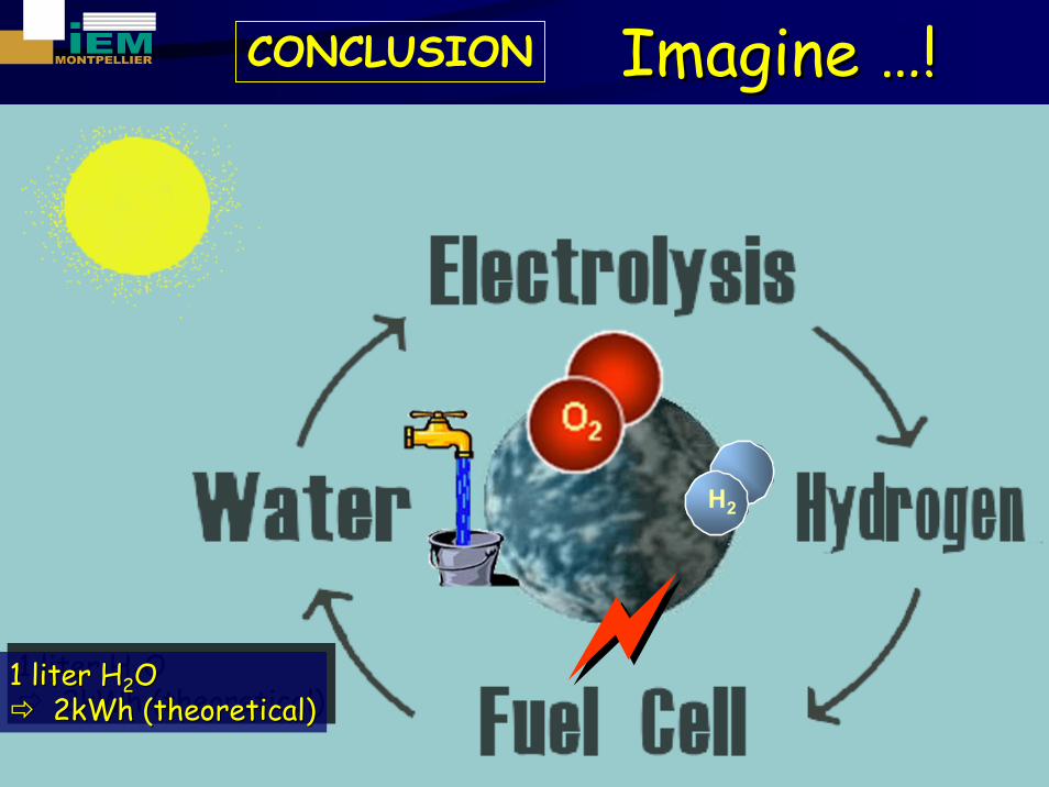
1 liter H2O 2kWh (theoretical)
1 liter H1 liter H22O O 2kWh (2kWh (theoreticaltheoretical))