1 CATEGORY: SPALLING TYPE: RIBBON FATIGUE SPALLING (also known as: Surface Initiated Spalling, Fatigue Path, Wreck Path, Wagon Tracks, Cat’s Tongue) AFFECTS: WORK ROLL AND BACK UP ROLL (HOT MILL and COLD MILL) CHARACTERISTICS This is the most common classification of spalling for work rolls and back up rolls in all applications. Ribbon fatigue spalling can be identified as one or sometimes multiple areas of spall type fracture on the roll barrel displaying one or more linear ribbon like features created by the propagation of cracks (The ribbon feature is sometime also referred to as: fatigue path, wreck path, wagon track, cat’s tongue, etc) . The surface texture and resolution (clarity) of the ribbons can vary greatly depending upon the roll material grade especially in work roll materials (AIC, HiCr and HSS) which can hinder identification, however, the shape and surface texture of the fatigue ribbon does typically exhibit a few characteristic features as follows: Location o Fatigue ribbons and associated spalling can be found at any point on the roll barrel from the very edges to anywhere in between. o The fatigue ribbon feature is typically located in the center of the fracture face at the deepest point (radially). o The sides of the ribbon path are usually distinct with secondary fracture flow extending longitudinally away from the sides and radially toward the surface. o Fracture faces may display a number of fatigue ribbons from one to multiple. Numerous fatigue ribbons in a cluster can sometimes be seen where multiple crack initiation sites were present. o Fatigue ribbon can propagate through the shell to the interface between the shell and core. Can be miss-diagnosed as shell-core interface separation spalling. Shape o Fatigue ribbons can widely vary in size and width from one incident to another, but primarily appears as a circumferentially oriented “path” propagating through and into the shell material (ie getting radially deeper). Typically gets wider with depth away from the surface where it initiated until an “equilibrium” width is reached Width can vary from very small (<5mm wide) to very wide (>150mm) Length of the ribbon path on the fracture face depends on how much has been exposed and total propagation length.
Transcript
1
CATEGORY: SPALLING
TYPE: RIBBON FATIGUE SPALLING
(also known as: Surface Initiated Spalling, Fatigue Path, Wreck
Path, Wagon Tracks, Cat’s Tongue)
AFFECTS: WORK ROLL AND BACK UP ROLL (HOT MILL and
COLD MILL)
CHARACTERISTICS
This is the most common classification of spalling for work rolls and back up rolls in
all applications. Ribbon fatigue spalling can be identified as one or sometimes
multiple areas of spall type fracture on the roll barrel displaying one or more linear
ribbon like features created by the propagation of cracks (The ribbon feature is
sometime also referred to as: fatigue path, wreck path, wagon track, cat’s tongue, etc).
The surface texture and resolution (clarity) of the ribbons can vary greatly depending
upon the roll material grade especially in work roll materials (AIC, HiCr and HSS)
which can hinder identification, however, the shape and surface texture of the fatigue
ribbon does typically exhibit a few characteristic features as follows:
Location
o Fatigue ribbons and associated spalling can be found at any point on
the roll barrel from the very edges to anywhere in between.
o The fatigue ribbon feature is typically located in the center of the
fracture face at the deepest point (radially).
o The sides of the ribbon path are usually distinct with secondary
fracture flow extending longitudinally away from the sides and radially
toward the surface.
o Fracture faces may display a number of fatigue ribbons from one to
multiple. Numerous fatigue ribbons in a cluster can sometimes be seen
where multiple crack initiation sites were present.
o Fatigue ribbon can propagate through the shell to the interface between
the shell and core. Can be miss-diagnosed as shell-core interface
separation spalling.
Shape
o Fatigue ribbons can widely vary in size and width from one incident to
another, but primarily appears as a circumferentially oriented “path”
propagating through and into the shell material (ie getting radially
deeper).
Typically gets wider with depth away from the surface where it
initiated until an “equilibrium” width is reached
Width can vary from very small (<5mm wide) to very wide
(>150mm)
Length of the ribbon path on the fracture face depends on how
much has been exposed and total propagation length.
2
Propagation length can be short (<50mm) up to several
revolutions around the roll circumference
o Fatigue ribbons can appear to propagate in a straight circumferentially
oriented path or can “meander” toward one side of the barrel length (or
even back and forth).
Fatigue Ribbon Surface Texture
o May appear discolored (stained) or burnished (shiny/rubbed) relative to
the surrounding fracture face
o Should exhibit fatigue arrest marks (also known as “beach” marks), but
may be difficult to distinguish especially in work roll materials (AIC,
HiCr Iron and HSS).
Arrest marks appear as regular, repeating, semi-circular “arcs”
or “horseshoes” located within the fatigue ribbon
The center of each arrest mark is always pointed in the
direction of crack propagation (almost like an arced arrow head
pointed in its direction of travel).
EXAMPLE
Example 1
Discolored fatigue ribbon on the spall fracture surface of a back up roll. Arrows
indicate direction of propagation
3
Example 2
Fatigue ribbon visible on the spall fracture surface of a work roll. Semi circular fan
shaped arrest or “beach marks” can clearly be seen (arrows). These arrest marks
indicate the direction for propagation of the ribbon in this case from top to bottom of
the image.
4
Example 2
Discolored fatigue ribbon at the centre of a back up roll barrel spall.
Arrows highlight the direction of propagation
Example 3
Discolored fatigue ribbon within the barrel spall of a work roll.
5
Example 4
Fatigue ribbons visible on the spall surface of work rolls (example 4 and 5). The full
extent of the crack ribbons has not been exposed by the spalling in each case.
Ultrasonic examination has been able to trace an initiation point.
Example 5
6
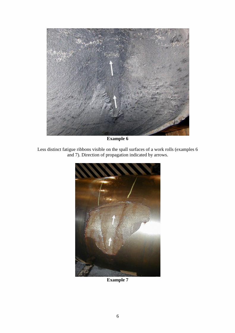
Example 6
Less distinct fatigue ribbons visible on the spall surfaces of a work rolls (examples 6
and 7). Direction of propagation indicated by arrows.
Example 7
7
Example 8
Fatigue ribbons visible within spalling at the edges of back up rolls. Arrows indicate