Evaluation of current logging tools Doc.nr: Version: Classification: Page: CATO2-WP3.04-D15 2012.02.14 Public 1 of 76 This document contains proprietary information of CATO 2 Program. All rights reserved Copying of (parts) of this document is prohibited without prior permission in writing CATO-2 Deliverable WP3.4-D15 Evaluation of current logging tools and industry practices for material selection and repairs Prepared by: Yolanda Kolenberg MSc (WEP) Hein van Heekeren MSc (WEP) Kornelius Boersma MSc (WEP) Mariene Gutierrez-Neri PhD (IF) Reviewed by: Alexander Nagelhout MSc (WEP) Approved by: J.Brouwer (CATO-2 Director)
Transcript
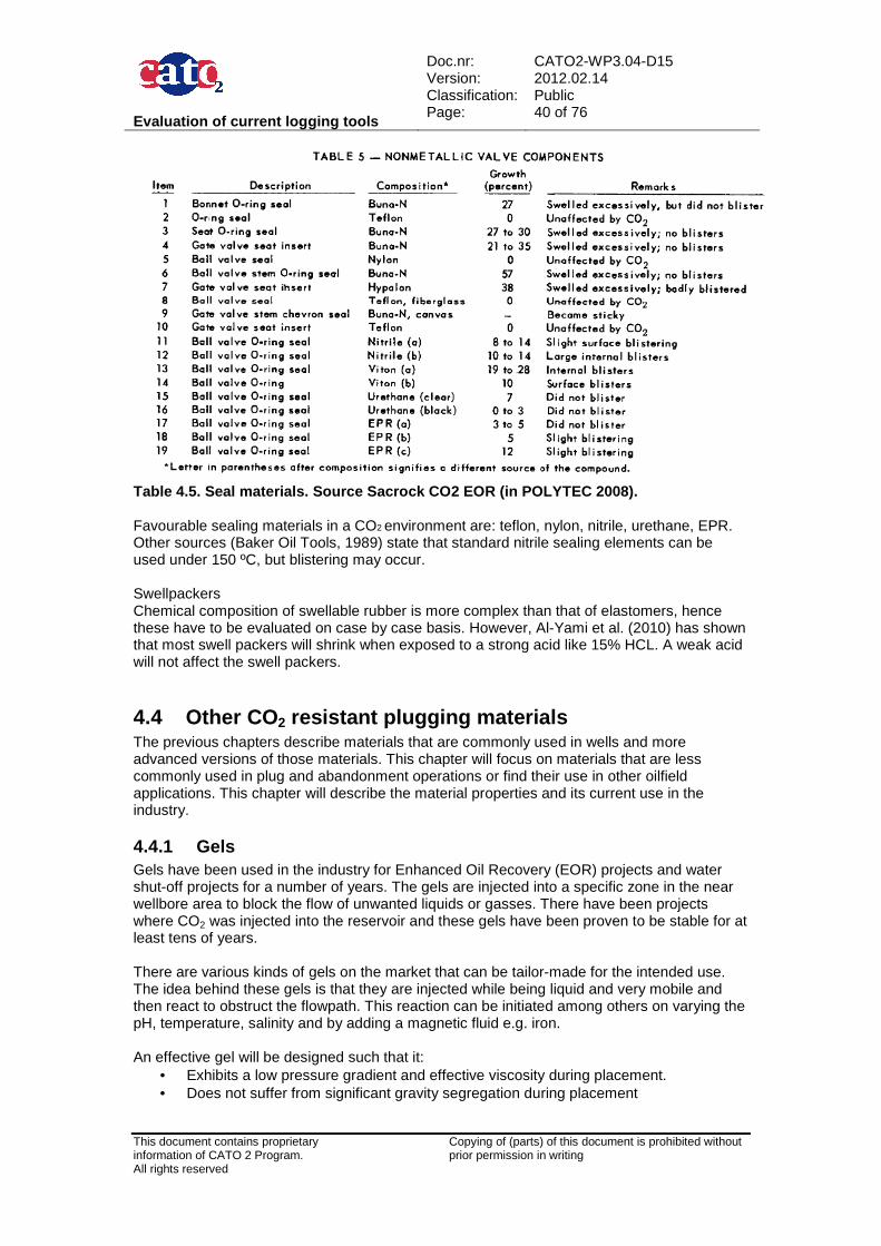
Evaluation of current logging tools
Doc.nr: Version: Classification: Page:
CATO2-WP3.04-D15 2012.02.14 Public 1 of 76
This document contains proprietary information of CATO 2 Program. All rights reserved
Copying of (parts) of this document is prohibited without prior permission in writing
CATO-2 Deliverable WP3.4-D15 Evaluation of current logging tools and
industry practices for material selection and repairs
This document contains proprietary information of CATO 2 Program. All rights reserved
Copying of (parts) of this document is prohibited without prior permission in writing
1 Executive Summary (restricted) Carbon capture and storage (CCS) is planned to take place in deep seated geological formations such as aquifers, coal seams or in depleted oil and gas fields. However, many uncertainties still exists regarding the long-term integrity of the reservoirs and how CO2 may leak out from the storage formations back to the surface. A possible leakpath is through active or abandoned wells. Within the wells, CO2 may leak through pre- existing leakpaths such as a poorly cemented annulus, micro annulus, leaking tubing or through the cement used to line and/or plug the well. Therefore, the confirmation of the integrity of the wells becomes of upmost importance. This report reviews the current industry practices for material selection and maintenance of the wells and evaluates the various monitoring and diagnostic tools for a qualitative assessment of the well integrity. Wells for CO2 injection can be newly drilled, or existing wells can be converted for CO2 injection. The well has a barrier function which is achieved by the use of a variety of materials such as steel, cement and elastomers. The selection of the well construction materials depends on down hole factors like temperature, pressure, pH, and stresses on the casing and the tubing. Besides that it is important to know the concentrations of H2S, chlorides, oxygen, water, the scaling potential and other contaminants in the CO2 stream and in the reservoir fluids. Existing standards for selection and specification of material used in the petroleum industry are developed and published by API, ISO, NORSOK, and the international corrosion society NACE. Experience is also gained from current industry practises with CO2 pipeline corrosion in the USA and more recently from some of the current CCS projects. When injecting more than 95% pure, dry CO2 in wells, the following guidelines have been compiled from industry experience and manufacturer tests:
• Carbon steel can be used when the CO2 is dry, the maximum pressure up to 180 bar, the maximum temperature 50 ºC and a maximum H2S content of 200 ppm. High pressure dry CO2 does not corrode carbon steel pipelines even with the presence of small amounts of methane, nitrogen or other contaminants.
• 13% Cr and Cr13+ alloys show good performance in a CO2 environment. However, it is not applicable in higher temperatures and in combination with low amounts of H2S. 13% Cr is also sensitive to oxygen corrosion.
• 22% or 25% Cr (super) duplex steel is better suited at high temperature and H2S content but it can suffer severe corrosion during acid treatment. It is therefore very important that when using this type of material the operational constraint is not to acid wash the well.
• Nickel alloys can also be considered if duplex steel cannot be used but are generally very expensive.
Another option could be to use a lower grade steel with an internal coating. However, the coating is not fully reliable, in particular at the tubular connections. Any breach will lead to rapid local corrosion and eroded fragments of the coating may block the perforations thus potentially reducing the injectivity of the CCS well. Also to avoid galvanic corrosion it is important not to mix low and high grade steels for tubing/casing. Portland-based cements which are the most commonly and widely used type of cements in well construction can degrade in the presence of CO2-rich fluids. Tests of Portland-based cement under CCS-like conditions, both in laboratory and field settings show this degradation consistently when exposed to CO2-rich fluids. The degradation process manifests in a series of zones, where the main cement components (i.e. C-S-H and Ca(OH)2) are replaced by
Evaluation of current logging tools
Doc.nr: Version: Classification: Page:
CATO2-WP3.04-D15 2012.02.14 Public 3 of 76
This document contains proprietary information of CATO 2 Program. All rights reserved
Copying of (parts) of this document is prohibited without prior permission in writing
carbonation reaction products altering the porosity and permeability of the exposed cement. These property changes can subsequently induce changes in the mechanical strength compromising even further the long-term integrity of the wellbore. Solutions to reduce degradation are replacing the main binding material (limestone) and to employ materials which reduce the permeability of the cement and subsequent penetration of CO2 in the cement matrix. There are CO2-resistant cements on the market that use these techniques to limit cement degradation. These cement types may not always be commercially available and, in some cases they need dedicated transport, storage and mixing measures. A good assessment of the condition of a well and its suitability for CCS can be made by implementing a measurement strategy that combines a variety of wellbore logging methods. Descriptions and functions are given of wellbore logging techniques used in the oil- and gas industry to evaluate the well integrity and monitor its condition for continued CO2 injection. The tools range from direct detection of barrier failure to evaluation of the barrier quality. A subdivision can be found in general leak detection, casing evaluation and cement evaluation. When an integrity issue is found there are several techniques currently used in the industry to remediate or abandon a well. There is not one type of remediation technique specifically to be used in CO2 wells and the best solution has to be determined on a case by case basis. Important factors for this are; desired durability, dimensional restrictions, required CO2 resistance, deployment method and costs. Besides the use of steel and/or cement also the injection of polymers can be considered which is however not yet a fully industry proven method. When the integrity of the well is impaired in such a way that remediation will be technically or economically unfeasible, abandonment of the damaged section is required. Above the abandoned section sidetracking can be considered or, when there is more concern for the integrity of the well in other sections, the complete well can be abandoned and a new well can be drilled. When (part of) a CO2 injection well is abandoned careful consideration must be given whether the abandoned section may become in contact with CO2. When the original well is drilled with materials that are CO2 resistant and its integrity can be established by wellbore logging, the well can be plugged conventionally with CO2 resistant materials. If this is not the case the well needs to be abandoned with a fullbore formation plug (FFP). This cement plug is placed opposite newly exposed impermeable caprock after locally a section of the casing and cement sheet are removed.
Evaluation of current logging tools
Doc.nr: Version: Classification: Page:
CATO2-WP3.04-D15 2012.02.14 Public 4 of 76
This document contains proprietary information of CATO 2 Program. All rights reserved
Copying of (parts) of this document is prohibited without prior permission in writing
Distribution List (this section shows the initial distribution list) External Copies Internal Copies Website
Document Change Record (this section shows the historical versions, with a short description of the updates) Version Nr of pages Short description of change Pages 2012.02.13 84 Final deliverable
Evaluation of current logging tools
Doc.nr: Version: Classification: Page:
CATO2-WP3.04-D15 2012.02.14 Public 5 of 76
This document contains proprietary information of CATO 2 Program. All rights reserved
Copying of (parts) of this document is prohibited without prior permission in writing
Table of Content 1 Executive Summary (restricted) .................... ........................................... 2 2 Applicable/Reference documents and Abbreviations .. .......................... 8
3 Introduction ...................................... ........................................................ 10 3.1 Wells and their lifecycle ................................................................................................... 10 3.2 Well barriers .................................................................................................................... 10 3.3 Current industry practices in well construction materials ................................................ 12 3.4 Logging............................................................................................................................ 13
4 Well Construction Materials ....................... ............................................. 14 4.1 Steel ................................................................................................................................ 15
4.1.2 Steel types and Iron Alloys in use for Well Construction ......................................... 17 4.1.2.1 Iron alloy phases .................................................................................................. 17 4.1.2.2 Technical specification CRA groups 1-2-3-4 ........................................................ 18
4.1.3 Steel material selection for corrosive systems ........................................................ 20 4.1.3.1 CO2 ....................................................................................................................... 20 4.1.3.2 H2S ....................................................................................................................... 20 4.1.3.3 CO2 and H2S ........................................................................................................ 20 4.1.3.4 Corrosion testing .................................................................................................. 21
4.1.4 Wellhead and X-mass Tree Equipment ................................................................... 21 4.1.4.1 Existing norms ...................................................................................................... 21
4.1.5 Tubing and Casing ................................................................................................... 22 4.1.5.1 Existing norms ...................................................................................................... 22 4.1.5.2 Corrosion rates ..................................................................................................... 22 4.1.5.3 Materials currently used in the industry................................................................ 22
4.2.1.1 Main degradation mechanisms ............................................................................ 28 4.2.1.2 Effects of curing conditions .................................................................................. 30 4.2.1.3 Effects of fluid-type exposure ............................................................................... 30 4.2.1.4 Dependence on additives used ............................................................................ 31 4.2.1.5 Main conclusions for Portland-based cement ...................................................... 32
4.2.2 Non-Portland cements ............................................................................................. 33 4.2.2.1 Performance of non-Portland cements under CO2 exposure .............................. 36 4.2.2.2 Considerations when employing non-Portland cements ...................................... 37
4.2.3 Cementing practices ................................................................................................ 37 4.3 Seal materials – Elastomers and Swell Packers............................................................. 39 4.4 Other CO2 resistant plugging materials .......................................................................... 40
4.4.1 Gels .......................................................................................................................... 40 4.4.2 Bright water .............................................................................................................. 41 4.4.3 Resins ...................................................................................................................... 41 4.4.4 Filling the voids with CO2 resistant materials ........................................................... 41
5 Wellbore monitoring and diagnostic tools .......... .................................. 42 5.1 Logging and monitoring methods .................................................................................... 42
Evaluation of current logging tools
Doc.nr: Version: Classification: Page:
CATO2-WP3.04-D15 2012.02.14 Public 6 of 76
This document contains proprietary information of CATO 2 Program. All rights reserved
Copying of (parts) of this document is prohibited without prior permission in writing
5.1.1 Leak detection .......................................................................................................... 42 5.1.1.1 Ultrasonic leak detector ........................................................................................ 42 5.1.1.2 Surface wellhead pressure ................................................................................... 42 5.1.1.3 Down hole camera ............................................................................................... 42 5.1.1.4 (Continuous) temperature measurement ............................................................. 42
5.2 Selecting logging methods .............................................................................................. 45 5.2.1 Initial state of well integrity ....................................................................................... 46 5.2.2 Well integrity during operation ................................................................................. 46 5.2.3 Abandonment ........................................................................................................... 46
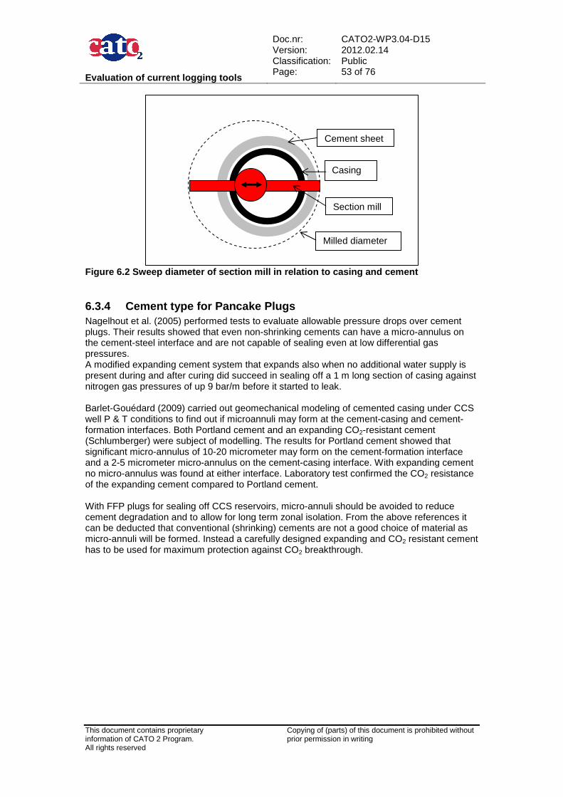
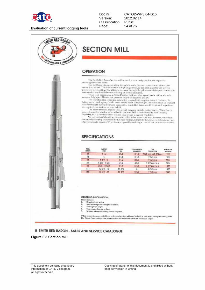
6.3 Abandonment .................................................................................................................. 50 6.3.1 Plugging of the near wellbore area .......................................................................... 50 6.3.2 Sealing the space under the bottom plug ................................................................ 51 6.3.3 Fullbore Formation Plug (Pancake plug) ................................................................. 51 6.3.4 Cement type for Pancake Plugs .............................................................................. 53
7 Current Industry Practises in CO 2 Injection ........................................ .. 55 7.1 K12-B in the Netherlands ................................................................................................ 55 7.2 Sleipner ........................................................................................................................... 55 7.3 Snøhvit ............................................................................................................................ 56 7.4 Gorgon field ..................................................................................................................... 56 7.5 Lacq ................................................................................................................................. 56 7.6 RECOPOL ....................................................................................................................... 57 7.7 CO2 Sink ......................................................................................................................... 58 7.8 In Salah ........................................................................................................................... 58
9.2.1 ISO ........................................................................................................................... 65 9.2.2 API & NACE ............................................................................................................. 65 9.2.3 NORSOK ................................................................................................................. 66
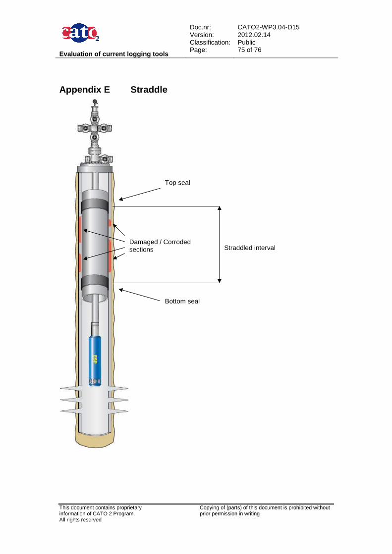
Appendices ........................................ ............................................................... 67 Appendix A Iron Alloy Phases .............................................................................................. 67 Appendix B Corrosion Rate and Selection Guide ................................................................ 68 Appendix C Watersolubility in CO2 and Drying.................................................................... 72 Appendix D HOMCO Patch .................................................................................................. 73 Appendix E Straddle ............................................................................................................ 75 Appendix F Expandable Patch............................................................................................. 76
Evaluation of current logging tools
Doc.nr: Version: Classification: Page:
CATO2-WP3.04-D15 2012.02.14 Public 8 of 76
This document contains proprietary information of CATO 2 Program. All rights reserved
Copying of (parts) of this document is prohibited without prior permission in writing
2 Applicable/Reference documents and Abbreviations
2.1 Applicable Documents (Applicable Documents, including their version, are documents that are the “legal” basis to the work performed) Title Doc nr Version AD-01a Beschikking (Subsidieverlening
CATO-2 programma verplichtingnummer 1-6843
ET/ED/9078040 2009.07.09
AD-01b Wijzigingsaanvraag op subsidieverlening CATO-2 programma verplichtingennr. 1-6843
AD-01d Toezegging CATO-2b FES10036GXDU 2010.08.05 AD-01f Besluit wijziging project CATO2b FES1003AQ1FU 2010.09.21 AD-02a Consortium Agreement CATO-2-CA 2009.09.07 AD-02b CATO-2 Consortium Agreement CATO-2-CA 2010.09.09 AD-03a Program Plan 2009 CATO2-WP0.A-D.03 2009.09.17 AD-03b Program Plan 2010 CATO2-WP0.A-D.03 2010.09.30 AD-03c Program Plan 2011 CATO2-WP0.A-D.03 2010.12.07 AD-03d Program Plan 2012 CATO2-WP0.A-D.03 2011.12.12
2.2 Reference Documents (Reference Documents are referred to in the document) Title Doc nr Version/issue Date
2.3 Abbreviations (this refers to abbreviations used in this document) API American Petroleum Institute BHT Bottom Hole Temperature CBL Cement bond log CCS Carbon Capture and Storage CO2 Carbon dioxide Cr Chromium DTS Distributed Temperature Sensing EM Electro-magnetic EOR Enhanced Oil Recovery FFP Fullbore Formation Plug H2S Hydrogen sulphide ID Internal diameter ISO International Organization for Standardization
Evaluation of current logging tools
Doc.nr: Version: Classification: Page:
CATO2-WP3.04-D15 2012.02.14 Public 9 of 76
This document contains proprietary information of CATO 2 Program. All rights reserved
Copying of (parts) of this document is prohibited without prior permission in writing
MMS Minerals Management Service NACE National Association of Corrosion Engineers OD Outside diameter PNL Pulsed neutron log ppm Parts per million SSC Sulfide Stress Corrosion Cracking SSV Surface safety valve SSRT Slow Strain Rate Tensile Test VDL Variable density log WEP Well Engineering Partners
Evaluation of current logging tools
Doc.nr: Version: Classification: Page:
CATO2-WP3.04-D15 2012.02.14 Public 10 of 76
This document contains proprietary information of CATO 2 Program. All rights reserved
Copying of (parts) of this document is prohibited without prior permission in writing
3 Introduction Carbon capture and storage (CCS) is planned to take place in deep seated geological formations such as aquifers, coal seams or in depleted oil and gas fields. The integrity of a well is a very important issue for CCS, because the wellbore can provide a potential leakage pathway for the stored CO2 in the reservoir to the overburden, and finally to the surface. Many uncertainties still exists regarding the long-term integrity of CO2 reservoirs and how CO2 may leak out from the storage formations back to the surface. This possible leakage pathway may be through an active or an abandoned well. Within the well, CO2 may leak through an already existing leakage pathway such as a poorly cemented annulus, leaking tubing or through the cement used to line and/or plug the well. Therefore the confirmation of the integrity of the well is of uppermost importance. The goal of this report is to evaluate the current industry practices for material selection to build a well, also various monitoring and diagnostic tools that can confirm the integrity of the well are evaluated. The remediation techniques for a well that have an integrity problem are discussed and abandonment methods are examined. Current industry practises with CO2 injection projects are given in this report.
3.1 Wells and their lifecycle When a potential site is selected and characterized for underground CO2 sequestration, a well is required to gain access to the reservoir. A well for CO2 storage can be newly drilled, or an existing well can be made appropriate for CO2 storage. The lifetime of a well for CO2 injection consists of several phases: a pre-injection phase, the CO2 injection phase, and a permanent abandonment phase. In all cases the well should have good, trustful barriers to prevent flow from the reservoir, through and along the well, to the surface at all times. During the pre-injection phase an existing or planned well will have to be evaluated on its integrity and the injection behaviour needs to be determined. This process of evaluation will require input from a detailed geological study, the reservoir characteristics and the planned injection fluid parameters. The injection phase itself can have a duration of up to 30 years, this depends on local conditions and the injection rate. It is important that during this phase the integrity of the well is monitored and evaluated. When a well is permanently abandonment good barrier functions require to be maintained at all times. During all phases the integrity of the well barriers need to be ensured. It is necessary to consider corrosion of steel and degeneration of cement by water, reservoir fluids, and solids from the environment during all phases of the wells lifecycle. It is known that CO2 and other associated compounds can have a big influence on these well construction materials under certain conditions. During and after the injection period, the CO2 can be hydrated with water that is already present in the reservoir. The wet CO2 and the resulting acid brine can reach the well. This acidic brine can corrode the steel casing and can degrade the cement protecting the steel casing. Corrosion mechanisms are described in section 4.1.1, and the degradation mechanisms of the cement are described in section 4.2.1.1.
3.2 Well barriers A possible leakage pathway is through an active or abandoned well. Within a well, CO2 may leak through an already existing leakage pathway such as an annulus or a fracture, or through the cement used to line and/or plug the well. Therefore confirmation of the integrity of the well becomes of uppermost importance.
Evaluation of current logging tools
Doc.nr: Version: Classification: Page:
CATO2-WP3.04-D15 2012.02.14 Public 11 of 76
This document contains proprietary information of CATO 2 Program. All rights reserved
Copying of (parts) of this document is prohibited without prior permission in writing
Figure 3.1. Sketch of typical well with primary and secondary barriers indicated (Alesio et al., 2011) A proper process of evaluation of an existing and/or a newly drilled well should consist of:
• Identification of the well barriers in relation to the local geology. • Assessment of the quality of the barriers. • Definition of the required design parameters and potential remediation techniques for
the well barriers.
Evaluation of current logging tools
Doc.nr: Version: Classification: Page:
CATO2-WP3.04-D15 2012.02.14 Public 12 of 76
This document contains proprietary information of CATO 2 Program. All rights reserved
Copying of (parts) of this document is prohibited without prior permission in writing
A well barrier consists of an envelope of one or several dependent barrier elements preventing fluids or gases from flowing unintentionally from the formation. The barrier function in the wellbore is achieved by a variety of materials such as steel, cement and elastomers. This study will evaluate the compatibility of these materials with the CO2 and the down hole conditions that exist in the reservoir, refer to Chapter 4. Next to that the various diagnostic methods that are capable of verifying whether the intended barrier function is achieved will be discussed in Chapter 5. During the injection phase two barrier envelopes need to be in place these are referred to as primary and secondary barriers, refer to Figure 3.1. If the primary barrier fails, the secondary one is present to contain the reservoir fluids within the well. The primary barrier typically includes the production tubing, packer, and safety valve; the secondary barrier comprises the cement outside the production casing, the production casing, and the wellhead.
3.3 Current industry practices in well construction materials Casing is a series of joints of pipe that are threaded together to make one long string; this pipe is used to seal of the formation from the wellbore. The casing strings are designed with respect to size, grade, and setting depth. The size of the casings must be selected in such a way that there is sufficient room inside each to install subsequent casings, run drilling tools or the completion. Casing grade is determined primarily by the operating pressure, temperature, and the corrosive nature of the fluids to which the casing will be exposed. Injection casings in CCS projects may be subjected to strong corrosion resulting from the aggressive behaviour of CO2. When CO2 is injected there could be a risk of damaging the casing and this could result in flow of CO2 to the overburden. See chapter 4.1 for a detailed description on corrosion mechanisms of steel types, and their behaviour in respect to CO2. When casing has been lowered to the bottom of a wellbore it is cemented in place. The purpose of the cement is to seal the formations behind the casing. When there are problems with a well or a section thereof cement can be used to plug the well. The most commonly used cement is Portland cement. Additives may be mixed with Portland cement to alter the physical properties as required. In order for CO2 to degrade the cement, water is required. Water sources can be either connate water, free water in cement or free water resulting from capillary condensation. Note that dry supercritical CO2 quickly becomes hydrated in the reservoir by absorbing connate water. There are two principles employed to reduce cement degradation. This consists of replacing the main binding material, limestone, with a material that is less susceptible for CO2 corrosion. And to employ materials that reduce the permeability of the cement and therefore penetration of the CO2 into the cement. There are CO2-resistant cements on the market that use these techniques to limit cement degradation, for instance the CO2-resistant cement Evercrete by Schlumberger and CorrosaCem line by Halliburton. Chapter 4.2 gives a comprehensive delineation on cement types used in well construction. Cementing practices also have an influence on the quality of the cement sheet. During the operational live of the well the primary cement sheet may have cracked. This can happen for instance when a high annular pressure has been applied or when the cement was too weak for the operational conditions. When formed, cracks most likely develop in a radial way from the casing outwards but they may interconnect vertically. Micro-annuli can result as well when the casing pressure is released and the casing contracts. Channels, cracks and micro-annuli resulting from the above mentioned situations allow CO2 gas to migrate upwards into the cement sheet, degrading the cement sheet relatively rapidly. Combined with casing corrosion from the in- and outside, zonal isolation will be lost. CO2 gas can then migrate to higher formations, into the casing annulus or even out into the open.
Evaluation of current logging tools
Doc.nr: Version: Classification: Page:
CATO2-WP3.04-D15 2012.02.14 Public 13 of 76
This document contains proprietary information of CATO 2 Program. All rights reserved
Copying of (parts) of this document is prohibited without prior permission in writing
The existing standards used in the oil and gas industry are developed and published by several parties and listed in Table 3.1. In this report in sections 4.1.4 to 4.1.7 attention will be given on the existing norms for wellhead and x-mass tree equipment, tubing and casing, threaded connections, and completion accessories. The most useful of these normative references are given in section 9.2. API American Petroleum Institute ISO International Organization for Standardization NACE International the international corrosion society NORSOK Standards developed by the Norwegian petroleum industry Table 3.1 International Standards/ Normative refere nces.
3.4 Logging Well integrity can be checked by using various measurements. The most common method of diagnostic measurement is done by the insertion of tools in the well by wire line or tubing, this is called logging. Other measurements can be read out on surface from sensors that are installed in the well. There are some general monitoring methods that give a qualitative assessment of the well integrity, and more specific integrity measurements that give more quantitative information about the well. This report will describe both measurements and focus on the sensitivity of the tools and how to optimize the monitoring by combining the different tools in an efficient way, refer to chapter 5.
Evaluation of current logging tools
Doc.nr: Version: Classification: Page:
CATO2-WP3.04-D15 2012.02.14 Public 14 of 76
This document contains proprietary information of CATO 2 Program. All rights reserved
Copying of (parts) of this document is prohibited without prior permission in writing
4 Well Construction Materials This chapter describes the construction materials to build a well. Well construction material consist of various types of steel, cement, and seal materials, refer Figure 4.1. The presence of CO2 and other relevant in situ conditions influence degradation processes on the well construction materials. The well construction material steel is described in section 4.1, of where the corrosion is the mechanism for steel degeneration, see section 4.1.1. The steel types and iron alloys in use for the well construction are described in 4.1.2. The selection of material for corrosive systems is described in section 4.1.3. In section 4.1.4. to section 4.1.7 the items in use for building a well are described and their existing norms are given in the same paragraphs. Section 4.1.8. describes the situation in the Netherlands. Cement types for well construction are described in section 4.2. In section 4.2.1 the Portland type cements and their main degeneration processes, and their effects when using additives. And the influence of CO2 . Section 4.2.2 describes the Non-Portland based cements, which are more resistant to CO2. Cementing practices influencing the construction are described in section 4.2.3. Section 4.3 describes the seal materials used in wellheads and in down hole accessories. Section 4.4 describes other CO2 resistant plugging materials sometimes used for well operations.
X-mass tree (seals)Wellhead (seals)
Figure 4.1. Sketch well construction materials, cas ing and tubing with accessories, and cement (WEP, 2011).
Cement
Conductor
Surface casing
Production liner
Tubing
Safety valve (seals)
Liner hanger (seals)
Production casing
Packer (seals)
Evaluation of current logging tools
Doc.nr: Version: Classification: Page:
CATO2-WP3.04-D15 2012.02.14 Public 15 of 76
This document contains proprietary information of CATO 2 Program. All rights reserved
Copying of (parts) of this document is prohibited without prior permission in writing
4.1 Steel One of the main components used in the construction of a well is steel. The corrosion mechanisms of steel due to CO2 and H2S and other corrosion controlling factors are described in section 4.1.1. Besides the normal requirements for steel used for the construction of a well there are some areas that need special attention in the material selection process. The steel should be of such a grade that it is compatible with the project specific CO2 environment. In section 4.1.2 the steel types and iron alloys that are in use for well construction are described. Section 4.1.3 describes the steel material selection for corrosive systems. Steel is used for the tubing, casing, wellhead, x-mass tree and, completion accessories, see section 4.1.4 to section 4.1.7 where these various items in use for building a well are described. In section 4.1.8. the situation in the Netherlands is described.
4.1.1 Corrosion Corrosion can be defined as the destructive attack of a metal by chemical or electrochemical reactions with its environment. The consequences of corrosion can be severe, and include embrittlement of steel and surface cracking. Electrochemical corrosion occurs at the solid/fluid interface in water, water/oil and gas systems. It can occur in H2S (sour) systems, in CO2 (sweet) systems, or in a combination of both. In Figure 4.2 a pin and box coupling failures due to corrosion fatigue by H2S gas (1000 ppm) and 2% CO2 is shown. CO2 corrosion is described in section 4.1.1.2 and H2S corrosion is described in section 4.1.1.3.
Figure 4.2. A pin and box coupling failure due to H 2S gas (1000 ppm) + 2% CO 2.
4.1.1.1 Corrosion Controlling Factors CO2 corrosion is strongly influenced by a wide number of factors:
• Presence of water: an oil-wet system protects from corrosion. • CO2-content: if the partial pressure exceeds 2 bar, corrosion occurs in a water wet
environment. (Partial pressure = total absolute pressure x volume fraction of gas component).
• H2S-content: even in low concentrations and in combination with CO2 this mixture can cause severe corrosion, in particular sulphide stress cracking.
• Oxygen content and content of other oxidising agents.
Evaluation of current logging tools
Doc.nr: Version: Classification: Page:
CATO2-WP3.04-D15 2012.02.14 Public 16 of 76
This document contains proprietary information of CATO 2 Program. All rights reserved
Copying of (parts) of this document is prohibited without prior permission in writing
• Chloride content: chlorides enhance pitting and other localised corrosion. In general martensitic stainless alloys (Cr-13/22) are more susceptible to chloride stress cracking than carbon steel.
• Temperature: when over 150°C, a dramatic increase in corrosion rate occurs, generally the corrosive reaction accelerates with increasing temperature.
• pH: corrosion is increased by acidity. • Fluid velocity: a high flow regime can remove a protective film. • Condensing conditions; if water drops out of the gas stream, corrosion will occur. • Pressure: increasing pressures result in an increase in stress related failures. • (Imposed) Electric currents. • Mixing of metals: galvanic corrosion.
If CO2 is injected in a dry supercritical state, the corrosion risk is low, because the corrosion rate of metals in presence of dry supercritical CO2 is very low. In that case, carbon steel can be used, sometimes with the help of corrosion inhibitors. After the injection period, during the long-term storage phase, the supercritical CO2 can be hydrated with water present in the reservoir and wet CO2 and the resulting acid brine can reach the well. This acid brine can corrode the steel casing.
4.1.1.2 CO2 corrosion In a wet CO2 environment; carbon dioxide dissolves in water to form carbonic acid. This results in acid brine that causes general corrosion or a localised attack on the metal surface, resulting in pits, crevices, ringworm or guttering. Pitting is in particular worrying since it can result in a rapid perforation of the tubing or casing (see Figure 4.3). Reported CO2 corrosion rates for carbon steel are more than 10 mm/yr. CO2 + H2O � H+ + HCO3
-
2 (H+ + HC03
-) + Fe � Fe2+ + 2 HCO3- + H2
In the process of carbon steel corrosion an iron oxide film is formed which is an active form of corrosion since corrosion continues after the film has formed. Formation of Fe(HCO3)2 occurs when steel is in contact with wet CO2 With stainless steel corrosion a passive corrosion layer is formed of chromium (III) oxide, Cr2O3, which stops corrosion. This layer quickly reforms when damaged but can deteriorate as a function of temperature, chlorides and, pH. Passiveness is enhanced by chromium, molybdenum, nickel, and vanadium.
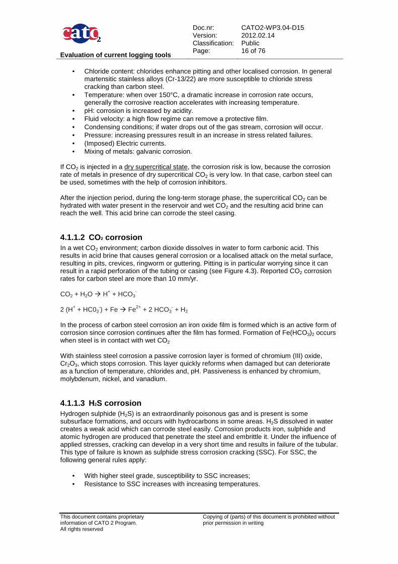
4.1.1.3 H2S corrosion Hydrogen sulphide (H2S) is an extraordinarily poisonous gas and is present is some subsurface formations, and occurs with hydrocarbons in some areas. H2S dissolved in water creates a weak acid which can corrode steel easily. Corrosion products iron, sulphide and atomic hydrogen are produced that penetrate the steel and embrittle it. Under the influence of applied stresses, cracking can develop in a very short time and results in failure of the tubular. This type of failure is known as sulphide stress corrosion cracking (SSC). For SSC, the following general rules apply:
• With higher steel grade, susceptibility to SSC increases; • Resistance to SSC increases with increasing temperatures.
Evaluation of current logging tools
Doc.nr: Version: Classification: Page:
CATO2-WP3.04-D15 2012.02.14 Public 17 of 76
This document contains proprietary information of CATO 2 Program. All rights reserved
Copying of (parts) of this document is prohibited without prior permission in writing
The NACE International document MR 0175, which is related to the ISO 15156 document, gives a comprehensive description on materials for use in H2S- containing environments in the oil and gas production industry, covering several steel types, iron alloys and CRA’s (corrosion-resistant alloys). NACE TM 0177 addresses the testing of metals subjected to tensile stresses for resistance to cracking failure in low pH aqueous environments containing H2S, covering sulphide stress cracking (room temperature, atmospheric pressure) and stress corrosion cracking (elevated temperatures and pressures).
Figure 4.3. A pipe corroded due to H 2S gas (1000 ppm) + 2 % CO 2.
4.1.2 Steel types and Iron Alloys in use for Well C onstruction Steel types for well construction are, with increasing corrosion resistance:
• Carbon steel (< 2.1% carbon). Standard steel grades: K55, N/L-80, P-110. • Martensitic stainless / corrosion resistant Cr steel (contains at least 11.5% chromium)
– e.g. Cr13 and Cr22. Forms a passive layer which is thermodynamically and chemically stable.
• Super martensitic stainless steel: contains less carbon and more nickel and molybdenum, and is more resistant to corrosion than normal Cr13 steel, e.g. Super Cr13 from Vallourec & Mannesmann. In the SINTEF 2007 report (Randhol et al., 2007) it is said that Super Cr13 is 5 times to 44 times more resistant to corrosion than Cr13 (depending on temperature).
• Ferritic austenitic steel alloy: contains chromium, manganese, nickel, vanadium. Characterised by: Low C-content, mixture between austenite/ferrite is stronger than austenitic steel, and improved corrosion resistance in particular against local corrosion as pitting, stress cracking.
• Duplex or superduplex steel; see Page 20 for the description of duplex steel. • Austenitic / super austenitic steel alloys: mostly nickel and cobalt alloys like Inconel
and Hastelloy, for applications in highly corrosive environments. For the phase diagram of iron alloy phases see Appendix A Iron Alloy Phases.
4.1.2.1 Iron alloy phases Different forms and mixtures of carbon-iron steel exist. The purpose is to balance tensile strength with brittleness / ductility as a function of process temperature and carbon content. Steel is heat treated in different processes and with different results:
Evaluation of current logging tools
Doc.nr: Version: Classification: Page:
CATO2-WP3.04-D15 2012.02.14 Public 18 of 76
This document contains proprietary information of CATO 2 Program. All rights reserved
Copying of (parts) of this document is prohibited without prior permission in writing
1. Heating to form austenite; 2. Quenching to produce martensite; 3. Tempering results in different mixtures of ferrite and cementite. Austenite:
• Is a state of solid solution of iron and other elements (mostly carbon); • Is formed in carbon steel above 700 ºC; • When it cools, a ferrite / cementite mixture is formed as dissolved carbon falls out of
solution; • Is stabilised by nickel.
Martensite:
• Is stabilised by nickel. • Formed by rapid cooling of the hot metal by dipping in water or oil bath (quenching),
when carbon is trapped in the crystal structure; • Increases tensile strength but material becomes more brittle;
Ferrite:
• Formed by slowly reheating and gradually cooling down of steel to allow carbon to diffuse out of the crystal structure and to form intermetallic compounds, which strengthen the overall crystal structure.
For manufacturing tubulars made of CRA (Corrosion Resistant Alloy) there are essentially two processes. Pipe made from alloys of Group 1 is hot rolled while pipe made from alloys of Group 2 is cold worked. The details of these processes are further explained below at the subsequent groups. CRA: Group 1 alloys comprises of martensitic and martensic-ferritic stainless steel. They are manufactured in a manner similar to carbon steel. The alloy is melted in an electric furnace then it is cast into ingots. The ingot is cast to form a billet, then heated to a suitable forging temperature, pierced and hot rolled to form a pipe. In order to achieve the mechanical properties the pipe is then quenched and tempered. CRA: Group 2, 3 and 4 alloys , such as duplex stainless steel and austeniticnickel-base alloys are fabricated in a different manner. After melting the material it is moulded to form an ingot or alternatively it can be continuously cast. The ingot is then forged into billets that are then extruded by a back extrusion press. In the majority of cases these steel grades are required in relatively high strengths which require the alloys to be cold worked. This cold work is performed on either cold drawing benches or in a cold pilger mill. Several passes on the draw bench may be necessary to achieve the correct strength while in general only a sizing pass and the finishing pass are requested on the pilger mill. The extrusion process, particularly when associated with cold working, is a costly and time-consuming tube-making process. The only available standard applicable to well construction is API Specification 5CT which only covers Group 1 grade 13 % Cr steel, mainly addressing mechanical and dimensional requirements. There are no standards available for materials of Groups 2 to 4.
4.1.2.2 Technical specification CRA groups 1-2-3-4 Group-1: Martensitic and Martensitic-Ferritic Stain less Steel The following features should be addressed in the technical specification for CO2 wells: Chemical composition:
Evaluation of current logging tools
Doc.nr: Version: Classification: Page:
CATO2-WP3.04-D15 2012.02.14 Public 19 of 76
This document contains proprietary information of CATO 2 Program. All rights reserved
Copying of (parts) of this document is prohibited without prior permission in writing
Sulphur content should be kept as low as possible. In fact, with its reduction hot workability increases considerably. With a sulphur content of 0.001% the hot workability is equivalent to that of carbon steel. This requirement is essential when working upset pipes. A value of 0.004% max. is realistic. Heat treatment: As mentioned before, one of the 13 Cr advantages over most other CRA material is that its strength is obtained by austenizing and tempering. Tubes are generally austenized at about 980 °C and because of its excellent hardenability they are air cooled which results in a fully martensitic structure. Tempering temperature is about 710 °C. NACE Standard MR- 01-75 requires double tempering for all martensitic stainless steels when used in sour environments, but there is no evidence that the double tempering improves the material resistance to H2S environments. Pipe manufacturers apply only one tempering. Microstructure checks: The only requirements for microstructures are related to delta ferrite content that shall not exceed 5 % and microstructures are required to have grain boundaries with no continuous precipitates. Mechanical Properties:
• Yield and tensile strength: the most common yield strength range varies from 80 to 110 kpsi with a minimum tensile strength of 90 kpsi. Depending on the service conditions and the suppliers manufacturing experience, a frequency of one tensile test for each lot of 100 or 200 tubes is reasonable.
• Hardness: the NACE MR-01-75 limit of 22 HRC for the 80 kpsi minimum yield strength, is a difficult task for type 420 due to its high yield-to-tensile-ratio. As suggested by API Spec 5 CT a more realistic value is 23 HRC. For upset pipes it is a good practice to limit the difference in hardness readings. Surface hardness tests with a portable Rockwell type tester is not recommended due to the unreliability of the measurement.
Impact Properties: The impact properties at low temperatures should be determined. Suggested test temperature is -10 °C. In case the minimum service temperature is less than -10 °C, the test temperature should be agreed with the manufacturer. Group 2: Duplex Stainless Steel Duplex stainless steel offers several advantages over martensitic alloys. The duplex grades have higher resistance to chloride stress corrosion cracking and also have good crevice and pitting corrosion resistance. They are available in a wide yield strength range from 65 kpsi up to 140 kpsi. To date there is no standard that covers such materials, therefore the following features need to be carefully evaluated: Chemical composition: In general it is recommended to be at the high end of the range for chromium and molybdenum, while the sulphur content should be kept as low as possible. Heat treatment: Depending on the final size, during manufacturing pipes may undergo a solution annealing treatment either after heat extrusion or between the intermediate and final cold working phases. The scope of the heat treatment is to obtain the best microstructure while maintaining carbides in solid solution and to relieve all stresses. This is achieved by heating to allow the carbon to come into solution followed by rapid cooling to keep carbon in solution. For the
Evaluation of current logging tools
Doc.nr: Version: Classification: Page:
CATO2-WP3.04-D15 2012.02.14 Public 20 of 76
This document contains proprietary information of CATO 2 Program. All rights reserved
Copying of (parts) of this document is prohibited without prior permission in writing
optimal stabilisation of ferritic and austenitic phases the material needs to receive a direct quenching after heat treatment. Hardness: The NACE MR-01-75 limit of 28 HRC for the solution annealed condition is acceptable. The limit of 36 HRC for the high-strength cold worked condition is not achievable for the 125/140 grades. A more realistic value is 37/38 HRC. Microstructure checks: The microstructure shall have a ferritic-austenitic structure. The microstructure is required to have grain boundaries with no continuous precipitates. Intermetallic phases, nitrides and carbides shall not exceed 1.0 %. Typically the ferrite volume fraction shall be in the range 40 % to 60 % for duplex and in the range 35 % to 55 % super duplex. Impact Properties: The impact properties at low temperatures should be determined. Suggested test temperature is -10 °C. In case the minimum service temperature is less than -10 °C, the test temperature should be agreed with the manufacturer. Moving to Group 3 and 4 alloys , the amount of alloying increases up to eight times more nickel and three times more molybdenum while maintaining about the same chromium content. Group 3 and 4 alloys are chosen for improved corrosion resistance to H2S, CO2 and chlorides. The chemistry of these alloys is very important. For the microstructures evaluate the absence of carbide precipitates at grain boundaries, that can compromise the corrosion resistance. Intermetallic phases, nitrides and carbides should not exceed 1.0 %.
4.1.3 Steel material selection for corrosive system s This section describes what type of steel to select in a particular corrosive system.
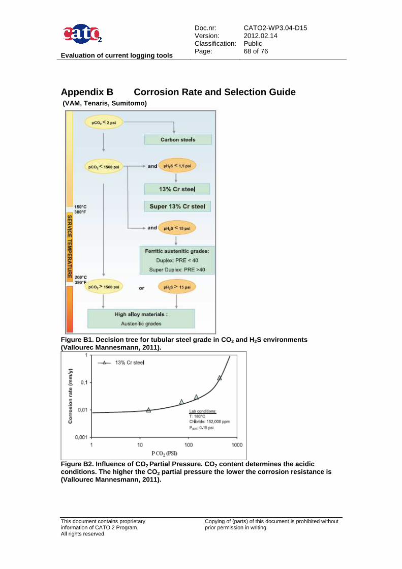
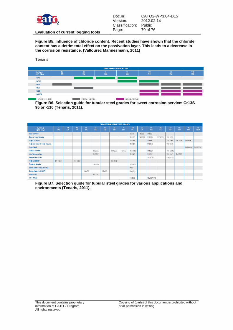
4.1.3.1 CO2 Martensitic stainless steel (Cr13 Group 1) is the material of choice for a CO2 environment providing that the temperature is not likely to exceed 150°C and the chloride content is not too high. Appendix B Corrosion Rate and Selection Guide shows corrosion rates as a function of Cl-concentration for different Cr13 grades. For temperatures exceeding 150°C a more highly alloyed tubular such as duplex can be considered. Carbonic acid causes general corrosion and pitting corrosion. Pitting is in particular worrying since it can result in a rapid perforation of the tubing or casing. Reported corrosion rates for carbon steel are more than 10 mm/yr.
4.1.3.2 H2S For well construction numerous materials are available that fit the NACE requirements; most common grades used are L-80 and T-95. It is not recommended to use L-80 in high H2S environments because of a to poor chemistry. Also available are proprietary materials with 100, 110 kpsi yield strength, but their usage is limited to production casing.
4.1.3.3 CO2 and H2S The presence of H2S in combination with CO2 aggravates corrosion. The use of martensitic steel tubing is restricted in the presence of H2S. Laboratory tests indicate that 13 % Cr is very susceptible to SSC hence its usage should be limited to pH2S < 0.5 psi (NACE). For higher values of pH2S more highly alloyed tubulars are required. Currently duplex stainless steels
Evaluation of current logging tools
Doc.nr: Version: Classification: Page:
CATO2-WP3.04-D15 2012.02.14 Public 21 of 76
This document contains proprietary information of CATO 2 Program. All rights reserved
Copying of (parts) of this document is prohibited without prior permission in writing
are the most commonly used candidates, these have however become very expensive over the last years. This has driven the development of new materials like “Super” 13 % Cr or 15 % Cr. Their field applications are increasing rapidly over the last years. Duplex Stainless Steels include 22 % Cr and 25 % Cr alternatives. The corrosion resistance of 25 % Cr is generally higher, both steels are strengthened by cold working. The “super duplex steels” have better performance than traditional duplex and can therefore be used in higher H2S partial pressure and chloride concentrations. Moving to worse conditions the “super austenitic” grades can provide the necessary corrosion resistance. They are Fe-base alloys and generally start with 25-27 % Cr and 31 % Ni, although there are many proprietary alternatives. Their corrosion resistance in CO2 plus H2S environments is quite good, they can be used up to 300 °C , above 1500 psi pCO2 and 1000 psi pH2S. They are also resistant to SSC in ambient temperature conditions. For the most severe conditions Group 4 materials can be used. These are austenitic Ni-based materials where nickel content ranges from 42 to 60 % while chromium content is in the range of 20-25 %, the molybdenum content starts with 3 % up to 16 %.
4.1.3.4 Corrosion testing In addition to chemical and metallurgical evaluations, corrosion testing is also recommended to verify that the materials will meet the expected performance. The specification should include accelerated corrosion tests because testing in standard conditions would take several months. Slow Strain Rate Tensile Test (SSRT) is a test that can usually be requested because of its short duration. The standard test conditions are: 300 °F, 100 psi H2S partial pressure at ambient pressure and temperature, 25 percent NaCl brine and 0.5 percent acetic acid.
4.1.4 Wellhead and X-mass Tree Equipment The wellhead or x-mass tree equipment is probably the single most important process item. The x-mass tree is an assembly of equipment, including tubing head adapters, valves, top connectors and chokes attached to the uppermost connection of the tubing head, used to control well production. The unit is a self-contained regulating and safety control barrier between the well fluids (at high pressure) and the surface process equipment. Based on EOR (Enhanced Oil Recovery) operations and acid gas disposal wells, broad experiences have been gained for wellhead valves and flanges for CO2 injection wells.
4.1.4.1 Existing norms API Specification 6A / ISO 10423 whereof the 20th edition is published in 2010 is the recognized industry standard for wellhead and x-mass tree equipment. It was formulated for design and describes in detail the material performance, processing and compositional requirements for bodies, bonnets, end and outlet connections, hub end connectors, hangers, back-pressure valves, bullplugs, valve-removal plugs, wear bushings, pressure-boundary penetrations and ring gaskets. To control pressure and fluid flows and provide for the availability of safe, dimensionally and functionally interchangeable equipment. API Specification 6A is also specified as the base standard for manufacture of subsea equipment in accordance with API Specification 17D. The current edition of API Specification 6A also includes requirements for Subsurface Safety Valves (SSV) and Underwater Safety Valves (USV). API Specification 6A requires that metals used for critical parts of equipment in sour service are in compliance with NACE MR 0175 / ISO 15156. Sour service is defined as any case where the absolute partial pressure of hydrogen sulfide (H2S) exceeds 0.05 psi.
Evaluation of current logging tools
Doc.nr: Version: Classification: Page:
CATO2-WP3.04-D15 2012.02.14 Public 22 of 76
This document contains proprietary information of CATO 2 Program. All rights reserved
Copying of (parts) of this document is prohibited without prior permission in writing
4.1.5 Tubing and Casing Carbon steel tubing and casing can be used for CO2 injection wells if no free water and no H2S is present. It is advised to increase the corrosion resistance of the well by using Cr13 or even a higher corrosion resistant material, when the presence of water cannot be excluded during the lifetime of the well. This can also be considered when the CO2 is not easily accessible, e.g. offshore, or in densely populated area where CO2 leaks are totally unacceptable.
4.1.5.1 Existing norms API Specification 5 concerns tubular goods, like casing, tubing, line pipe, and drill stems used in a well. API Spec 5B is a specification for the treading, gauging, and thread inspection of casing, tubing, and line pipe threads. Also criteria for connections are given. API Spec 5CRA (first edition 2010) / ISO 13680:2008 is the international specification for corrosion resistant alloy seamless tubes for use as casing, tubing and coupling stock. API Spec 5 CT specifies the technical delivery conditions for steel pipes for use as casing, tubing, plain-end casing liners, and pup joints. It covers the four groups of products to which that International standard is applicable and includes the grades for pipe used in the petroleum industry. These groups are: Group 1: all casing and tubing in Grades H, J, K, and N; Group 2: all casing and tubing in Grades C, L, M, and T; Group 3: All casing and tubing in Grade P; Group 4: All casing in Grade Q. The NORSOK M-001 standard provides general principles, is an engineering guidance and gives requirements for materials selection and corrosion protection for hydrocarbon production. NORSOK M-001 and the accompanying CO2 corrosion rate calculation model (M-506) will give corrosion rates as a function of local pressure and temperature conditions.
4.1.5.2 Corrosion rates The NORSOK M-506 corrosion rate model calculates the CO2 corrosion rate on basis of given temperature, pH, CO2 partial pressure and shear stress. A commonly applied upper limit for allowable corrosion is specified by NORSOK as 0.1 mm/yr. However, wet CO2 may corrode steel at a rate over 10 mm/yr. In Attachment B Corrosion Rate and Selection Guide Laboratory tests from Vallourec indicate for Cr13 maximum corrosion rates of ~1 mm/yr, depending on temperature, pH and chlorides. For carbon steel pipelines, corrosion rates can be less than 0.1 mm/yr when using 20 ppm CO2 corrosion inhibitor at 30° C / 72 bar (Visser, 2007).
4.1.5.3 Materials currently used in the industry For an overview of current industry materials selection recommendations for CO2 injection wells see Table 4.1, Table 4.2, and Table 4.3. For more information see Attachment B Corrosion Rate and Selection Guide. Note that pCO2 and pH2S are partial pressures: fraction of gas component x absolute pressure.
This document contains proprietary information of CATO 2 Program. All rights reserved
Copying of (parts) of this document is prohibited without prior permission in writing
Table 4.1. An overview of current industry material s selection recommendations for CO2 injection wells.
Table 4.2. Overview of material specification for c arbon steel CO 2 pipelines according to DYNAMIS (Visser, 2007). The following recommendations for carbon steel CO2 pipelines are made in the DYNAMIS report (Visser, 2007):
• Water content: has to be less than the solubility limit for applicable P and T conditions, see also Attachment C Water solubility in CO2 and drying.
• Maximum temperature: 50 °C to protect the pipeline coating. A summary of the materials of construction (MOC) commonly used for individual CO2 injection well components made for API is presented in Table 4.3.
Table 4.3. Example of CO 2 well component selection list for operation with w ater saturated CO 2 in the USA (Meyer, 2007). IPC = internally plastic coated.
Evaluation of current logging tools
Doc.nr: Version: Classification: Page:
CATO2-WP3.04-D15 2012.02.14 Public 24 of 76
This document contains proprietary information of CATO 2 Program. All rights reserved
Copying of (parts) of this document is prohibited without prior permission in writing
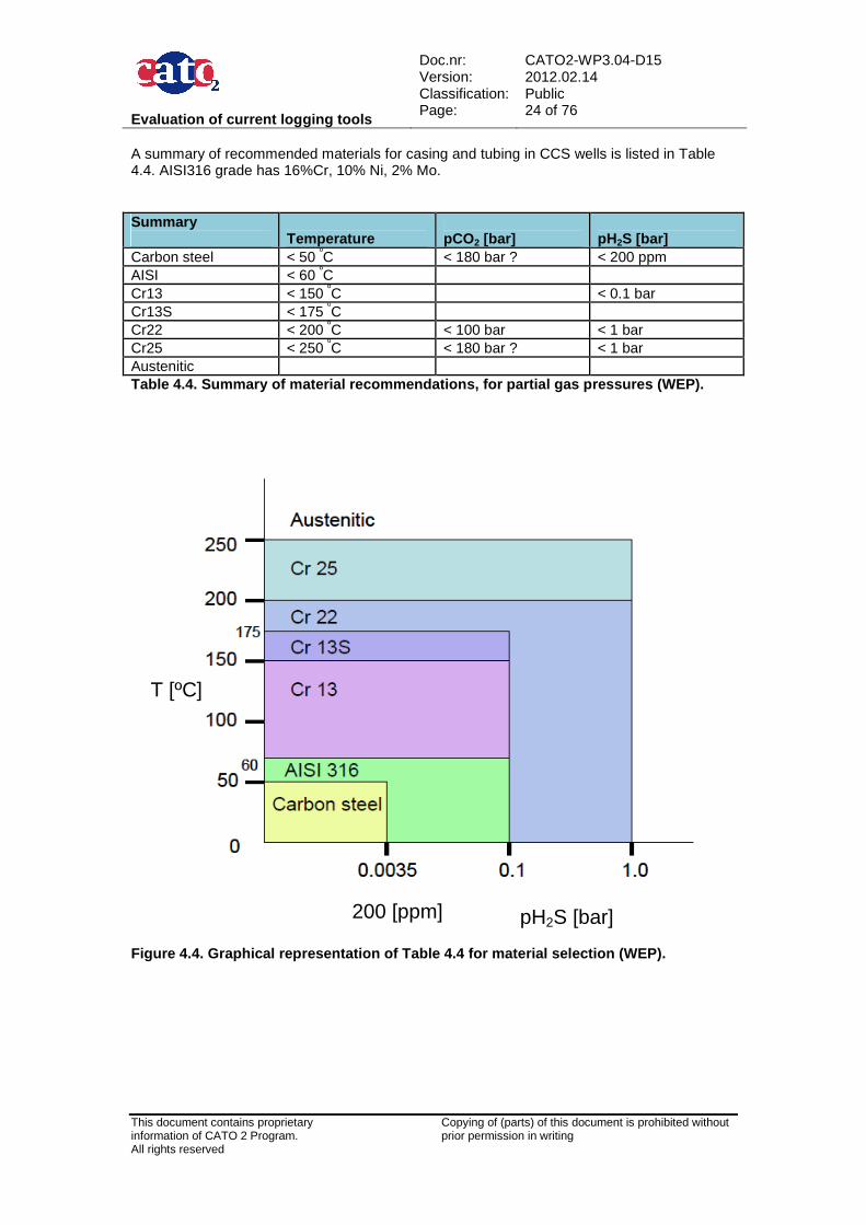
A summary of recommended materials for casing and tubing in CCS wells is listed in Table 4.4. AISI316 grade has 16%Cr, 10% Ni, 2% Mo. Summary
Temperature
pCO2 [bar]
pH2S [bar]
Carbon steel < 50 ºC < 180 bar ? < 200 ppm AISI < 60 ºC Cr13 < 150 ºC < 0.1 bar Cr13S < 175 ºC Cr22 < 200 ºC < 100 bar < 1 bar Cr25 < 250 ºC < 180 bar ? < 1 bar Austenitic Table 4.4. Summary of material recommendations, for partial gas pressures (WEP).
Figure 4.4. Graphical representation of Table 4.4 f or material selection (WEP).
pH2S [bar] 200 [ppm]
T [ºC]
Evaluation of current logging tools
Doc.nr: Version: Classification: Page:
CATO2-WP3.04-D15 2012.02.14 Public 25 of 76
This document contains proprietary information of CATO 2 Program. All rights reserved
Copying of (parts) of this document is prohibited without prior permission in writing
The effect of partial CO2 pressure is not fully understood since different values are given by various sources. NACE defines pH2S > 0.05 psi (0.0035 bar) to be sour conditions. Boundary conditions for material selection:
• If water is present it has to be less than the solubility limit for all conditions in the wellbore.
• CO2 concentration at 95% or more; nitrogen, hydrocarbons, oxygen each less than 4%.
• Effect of chlorides is left out since these are assumed to be absent in the injection flow. In lower part of the well chlorides may be present (connate water) and may hence affect the selected material, see Attachment B Corrosion Rate and Selection Guide.
Temperature is main discriminator, since this affects the actual chemical corrosion reaction the most, in particular removal of the passivation layer. The main uncertainty is the maximum pressure. Vallourec and Sumitomo recommend not to exceed 100 bar for Cr13S whereas carbon steel pipelines are operated up to 180 bar.
4.1.6 Threaded connections What applies to casing and tubing is also valid for threaded connections. Because the collars of the connections need to be from the same material as the tubular. The connection must provide sufficient pressure- and structural integrity. Connections exposed to CO2 have to be gas-tight with a metal to metal seal. In practise this will always be the case for converted hydrocarbon wells since these have been designed to constrain methane gas, which is more mobile than CO2. For new CO2 injection wells it should be stated that the same design and construction criteria have to be applied as for oil and gas wells. Detailed connection designs are described in API Specification 5B Specification for threading, gauging, and thread inspection of casing, tubing, and line pipe thread and ISO standards. Most vendors offer modified connection designs for improved performance like higher axial strength, reduced OD and improved pressure integrity. These so called premium connections are used for almost all casing and tubing applications in the North Sea. Premium connections use metal to metal seals which are the most reliable seals, especially at high pressure and temperature. Details on properties of most connections can be found in the annual casing and tubing Reference Tables published in the November and January editions of ‘World Oil’ magazine and are available at: http://www.worldoil.com/TechTables/WOTubingTables_2011.pdf.
4.1.7 Completion accessories The CO2 injection string consists of tubing and other equipment necessary to achieve optimal performance and safety during injection. The injection string is installed in the well after all casing and liners have been run and cemented in place as part of the well drilling process. Commonly used injection string components are:
• Tubing hanger and tubing joints • Connections, control lines • Down hole safety valve, seal bores • Permanent down hole gauge, injection packer • Landing nipples, pup joints, wireline entry guide
Evaluation of current logging tools
Doc.nr: Version: Classification: Page:
CATO2-WP3.04-D15 2012.02.14 Public 26 of 76
This document contains proprietary information of CATO 2 Program. All rights reserved
Copying of (parts) of this document is prohibited without prior permission in writing
Several of these components in the injection string are well barrier elements, like the down hole safety valve and the injection packer. For surface safety valve (SSV) specifications see API Specification 6A / ISO 10423. Completion components are almost always of a higher grade than tubing, 9Cr/1Mo or Cr13, to ensure a long service life in the well. The same material selection criteria as for tubing apply. Suppliers for completion accessories can supply sour service (H2S) components and as such in practise material selection for completions components has not been seen as problematic or critical. All injection string components should be chosen to be of same steel quality to avoid galvanic corrosion. It is very important that material quality is checked from the selected suppliers before installing their equipment in the well, as a wrong steel quality may lead to a rapid failure.
4.1.8 Situation in the Netherlands In the Netherlands almost all producing gas wells are completed with Cr13 tubing. For example The Groningen wells are competed with Cr13 tubing, where typical down hole conditions are 350 bar and 120 ºC, and free water (condensation) is present.
4.1.9 Conclusions 13% Cr shows good performance in CO2 environment. However, it is not applicable for higher temperatures (> 150 ºC) or in combination with even low amounts of H2S. 13Cr is also sensitive to oxygen corrosion. 22% or 25% Cr duplex steel is very costly and usually not an option for long pipe sections. However, even if 22% or 25% Cr is better suited at higher temperature and in combination with H2S, it can suffer severe corrosion during acid treatment. It is therefore very important that when using this type of material the operational constraint is not to acid wash the well. This needs to be well documented so that it is understood by the different disciplines during the life cycle of the well. Nickel alloys can also be considered if duplex steel cannot be used. Another option could be to use a lower grade steel with an internal coating. However, the coating is not reliable and any breach will lead to rapid corrosion and deterioration of the steel. Also fragments of the coating may clog up the injection perforations of the well. So the choice of material will largely depend on the conditions expected for the CO2 well. Furthermore it is important not to mix low grade metal seals with high grade tubing/casing metal. This will lead to galvanic corrosion due to the difference in electric potential between the metals. Limitations of use for steel and stainless alloys due to corrosion controlling factors are defined by various international standards like NORSOK M-001 and NACE MR 0175 / ISO 15156 (see also section 9.2: Normative references).
4.2 Cement Types The most likely locations for geological storage have already a history of oil, gas and or coalbed methane production. These locations are typically penetrated by a significant number of wells as a result of exploratory or production events. The wells may be active or abandoned and could be vulnerable to leakage through the cement used to line and/or plug the well. Figure 4.1 illustrates some of the potential leakage pathways that can occur in wells (Gasda et al, 2004).
Evaluation of current logging tools
Doc.nr: Version: Classification: Page:
CATO2-WP3.04-D15 2012.02.14 Public 27 of 76
This document contains proprietary information of CATO 2 Program. All rights reserved
Copying of (parts) of this document is prohibited without prior permission in writing
Figure 4.1. Potential leakage pathways in a well (G asda et al, 2004). A Portland-based cement is typically used for the cement fill and the cement well plug. When Portland cement is mixed with water, hydration products are formed containing mainly calcium silicate hydrate phases (C-S-H) and calcium hydroxide (Ca(OH)2), also referred to as portlandite. C-S-H comprises approximately 70% of the hydrated cement and is the main binding material, while Ca(OH)2 comprises about 15-20 % (Nelson and Guillot, 2006). A primary concern for CO2 injection wells are the reactions of these components with CO2-rich fluids (for instance carbonic acid H2CO3) which results when CO2 dissolves in water under down-hole conditions. Subsequent changes in porosity, density and texture due to dissolution/precipitation processes may impact the mechanical and physical properties of the wellbore cement creating eventually leakage pathways for CO2 and compromising the integrity of the sealing. In the following sections, results from experimental studies (laboratory and field studies) investigating the degree and rate of cement degradation are summarised. A general distinction is made for Portland-based cements and non-Portland based cements.
4.2.1 Portland-based cements According to the API, there are eight main classes of Portland cement, classes A – H. These are defined, with details of their intended use and their required chemical composition, in the API Specification 10A. Although this specification recommends to choice of cement to be made based on the expected well depth, in practice the choice should be taken based on Bottom Hole Temperature (BHT) and (with some exceptions) on pressure. Classes A-F Cement Classes A, B and C are intended for use in wells with static BHT up to 77°C (170°F). Class A is of general purpose, Class B is sulphate-resistant and Class C provides a high early-strength. Classes D, E and F are retarded cements intended for use in wells with static BHT up to 110°C (230°F), 145°C (290°F) and 160°C (320°F), respectively. When making a choice between these cement classes, it should be taken into account that these limits are flexible and that the setting time, which is the critical factor, can be modified by means of accelerators or retarders. Thus, in practice the choice is based not only on the expected temperature but also on the availability and convenience of maintaining the minimum number of cement types in stock.
Evaluation of current logging tools
Doc.nr: Version: Classification: Page:
CATO2-WP3.04-D15 2012.02.14 Public 28 of 76
This document contains proprietary information of CATO 2 Program. All rights reserved
Copying of (parts) of this document is prohibited without prior permission in writing
Cement types A-F may contain additives such as bentonite and pozzolans. Bentonite, up to 2%, is used to absorb the free water content. One of the disadvantages of using bentonite is that the resulting cement strength is lower. In contrast, pozzolans are siliceous materials which, in the presence of water and at temperatures over 60°C (140°F), will combine with lime (CaO or Ca(OH)2) to form cement phases. The most commonly used pozzolan is “fly ash”, a combustion product of coal. Pozzolans have two characteristics which are useful in cement slurries. The first is their lower density compared to the Portland cements, and can therefore result in a lighter slurry. The second is that it reacts with lime at elevated temperatures. When, for instance, 100 kg of Portland cement is hydrated, it produces about 20 kg of lime. This lime has no contribution to the cement strength and, as it is soluble, it will eventually leached out and weaken the cement. Adding pozzolan will remove this free lime, thus adding to the cement strength and reducing its permeability. The ratio of pozzolan-to-Portland cement varies between 35-65%. Classes G and H Because of the desirability of simplifying the range of cements in stock when deep wells are being drilled, cement Classes G and H were developed. These are neat cements, i.e., with no additives, which have been manufactured to closer tolerances than classes A - F and which can be used over a much wider range. Class G is widely used and is suitable, with appropriate additives, for cement jobs at surface all the way to TD, assuming a normal temperature gradient. Class H is suitable for the same range of depths and differs from Class G in its coarseness (more coarse) thus requiring less water. In addition, its availability is more limited. As classes G and H do not contain any additives, they have up to 1.4% more of free water than compared to classes A-F. All Portland-based cements will react and degrade in exposure to CO2. The main degradation processes are discussed below. The effects of additives on these processes are also briefly reviewed.
4.2.1.1 Main degradation mechanisms There are three main chemical reactions involved in the Portland cement-CO2 interaction (Duguid, 2008):
(1) formation of carbonic acid (H2CO3), (2) carbonation of C-S-H phases and/or Ca(OH)2 (3) dissolution of CaCO3:
Formation of carbonic acid . Carbonic acid (H2CO3) results from the dissolution of CO2 in water, as follows CO2 + H2O -> H2CO3 The sources of water can be not only the formation water but also the free water contained within the cement and the free water resulting from capillary condensation in the well. How much CO2 can dissolved in water will depend on the prevailing pressure, temperature and salinity level of the water. However, and in either case, the formation of carbonic acid causes a lowering in the pH value. Carbonation of cement hydrated phases (C-S-H and Ca (OH)2) When carbonic acid comes in contact with hydrated cement it will react to form calcium carbonate (CaCO3). Carbonic acid decomposes the C-S-H gel, the main binding component in the cement, into calcium carbonate and an amorphous silica and/or reacts with calcium hydroxide in the cement causing carbonation of Ca(OH)2 .The respective reactions for the C-S-H phases and calcium hydroxide are as follows:
Evaluation of current logging tools
Doc.nr: Version: Classification: Page:
CATO2-WP3.04-D15 2012.02.14 Public 29 of 76
This document contains proprietary information of CATO 2 Program. All rights reserved
Copying of (parts) of this document is prohibited without prior permission in writing
C-S-H + H2CO3 → CaCO3 + amorphous silica Ca(OH)2 + H2CO3→CaCO3 + 2H2O The carbonation reactions cause densification and an increase in hardness as CaCO3 takes up a larger volume than Ca(OH)2. Although the increase in strength may be desired, extensive carbonation can lead to the development of micro and macro cracks and to the loss of structural integrity (Carey et al, 2007). However, this increase in carbonation also results in a reduced porosity and permeability. A sort of zonal isolation is created where further CO2 diffusion into the cement is hindered and cement degradation is slowed down or even prevented (Kutchko et al., 2007). Dissolution of CaCO3 The carbonation zone that develops would seem enough to limit further cement degradation. However, CaCO3 is a soluble product and can continue to react with fresh carbonic acid to form water-soluble calcium bicarbonate. Ca(HCO3)2 will continue reacting with formation water to produce more CaCO3. The reactions are as follows: CaCO3 + H2CO3→Ca(HCO3)2 The overall effects of this reaction are an increase in porosity and permeability and a reduction in mechanical strength. In addition, the increase in porosity favours the CO2 diffusion further into the cement matrix. The main reaction mechanisms are illustrated in Figure 4.2.
Figure 4.2. Cement degradation mechanisms (modified from Kutchko et al., 2007). It should be noted that all the above-mentioned reactions can only take place in the presence of water. In addition, their rate is limited by the diffusion rate of CO2 and/or by its dissolution. Recalling that the amount of dissolved CO2 in water (and hence carbonic acid formation) will be controlled by variables such as pressure, temperature and salinity and have a direct impact on the degradation rate.
Evaluation of current logging tools
Doc.nr: Version: Classification: Page:
CATO2-WP3.04-D15 2012.02.14 Public 30 of 76
This document contains proprietary information of CATO 2 Program. All rights reserved
Copying of (parts) of this document is prohibited without prior permission in writing
4.2.1.2 Effects of curing conditions When a cement slurry is placed in the well, it may be exposed to temperatures ranging from freezing up to 350°C and pressures from near ambient up to 500 bar, depending on the geological conditions. Recent laboratory experiments have focused on studying the effect of conditions at which the cement was cured and the subsequent impact on the degree and rate of degradation when exposed to CO2 (Kutchko et al., 2007; Sauki and Irawan, 2010). The physical and chemical characteristics of cement can change considerably when cured at elevated temperatures and pressures as compared to curing at ambient conditions. When the hydrated cement sets at temperatures <80°C, the C-S-H phase formed is amorphous. When the setting temperature > 80°C the C-S-H will take a crystalline form. Focusing specifically on how setting conditions (in terms of pressure and temperature) influence the cement degradation by carbonic acid, the main findings can be summarised as follows:
• Depending on the in-situ curing conditions, the depth of alteration (i.e., depth of CO2 attack) decreases with higher temperature and pressures
• This may be attributed to the formation of well-defined band of calcite (CaCO3) which can better buffer the CO2 attack. Calcite reacts with CO2, a more uniform carbonization zone develops providing also a better isolation (see Figure 4.3)
• Existing and/or abandoned oil and gas wells in most cases undergo elevated temperature and pressure curing conditions. This can in turn provide less vulnerable conditions to the CO2 attack and limit the degree and degradation rate.
(a)
(b)
Figure 4.3. Shows the changes in cement structure f or different curing temperature at similar constant pressure. a) cement cured at 40°C; b) cement cured at 120°C. (Modified from Sauki and Irawan, 2010)
4.2.1.3 Effects of fluid-type exposure When CO2 is injected into a saline formation, it will continue moving and spreading as a separate, buoyant gas phase (supercritical phase) and/or will dissolve in the formation water. Wellbores can come into contact with both type of CO2 forms and the chemical interactions may differ. Experimental investigations focusing on the effects of cement degradation on the type of fluid exposure generally distinguee two types: 1) cement exposed to wet supercritical CO2; 2) cement exposed to CO2-saturated brine. The main findings are summarised below:
• Cement that it is exposed to wet supercritical CO2 and/or a CO2-saturated water/brine shows qualitatively the same degradation mechanisms (section 4.3.1.1)
Evaluation of current logging tools
Doc.nr: Version: Classification: Page:
CATO2-WP3.04-D15 2012.02.14 Public 31 of 76
This document contains proprietary information of CATO 2 Program. All rights reserved
Copying of (parts) of this document is prohibited without prior permission in writing
• However, the degradation rate is altered depending on type of fluid exposure. This is illustrated Figure 4.4. A cement exposed to wet supercritical CO2 will degrade faster than cement exposed to CO2- water saturated
This implies that along the well trajectory, different patterns (and rates) of cement degradation may be found. The upper part of the well will degrade faster as it is more likely to be in contact with wet supercritical CO2 due to its buoyant spreading. The lower part, which is more likely to be exposed to CO2 saturated fluid will follow the same degradation pattern but at a slower rate. a) b)
Figure 4.4. Comparison of degradation behaviour for cement exposed to wet CO 2 supercritical and CO 2 saturated in water (Taken from Barlet-Gouedard et al, 2006).
4.2.1.4 Dependence on additives used Most of the experimental results summarised above apply to clean cements (i.e. no additives). The following list summarises the most common additives used in cement and some of the experimental findings regarding their behaviour to CO2 exposure. Bentonite Cement containing bentonite makes it more susceptible to CO2 corrosion (Kutchko, 2007). API class A-F cements may contain bentonite to absorb the excess free water during hydration or to make the slurry lighter, therefore the use of these cements is not recommended for CCS conditions. In addition, existing wells are likely to have cement sheets containing bentonite due to bentonite added to the drilling mud and cement slurry. Pozzolans (fly ash) Cement with a high concentration of pozzolan is more susceptible to CO2 corrosion, but the altered cement zone is not damaged as much and some of the original strength and permeability is retained (Strazisar 2008). This also has been observed in the field (Crow, 2008) Accelerators The most widely used accelerator is calcium chloride (CaCl2), which is an ionic compound. Up to 4 % by mass of cement is typically added to the slurry. Sodium Chloride is also an accelerator in concentrations of up to about 95 kg/m3 in the mixing water. The salinity of seawater is within this range and if seawater is used as the mixing water, there seems to be an accelerating effect compared with fresh water slurries. The formation of CaCO3 in the fluid above packers sealing off a CO2-rich reservoir has been observed. It is suspected that this was formed when CO2 percolating by the packer reacts with calcium chloride following this reaction:
Evaluation of current logging tools
Doc.nr: Version: Classification: Page:
CATO2-WP3.04-D15 2012.02.14 Public 32 of 76
This document contains proprietary information of CATO 2 Program. All rights reserved
Copying of (parts) of this document is prohibited without prior permission in writing
CaCl2 + CO2 + H2O → CaCO3 + 2 HCl. Cements containing this accelerator may therefore be subject to faster degradation by CO2. The effect of the accelerator in the cement slurry may also be potentially reduced in the presence of CO2. Late setting of the cement may under certain conditions lead to gas-cutting of the cement sheet. Retarders The products sold as retarders are most commonly lignosulphonates. These are surface active agents and their effect in practice is to delay the onset of hydration for a certain period. Once hydration begins, it proceeds at the normal rate. Products which have a secondary retardation effect are usually either cellulose based or are also lignosulphonates. Cellulose based products, produce the retardation by binding the water and releasing it slowly. This allows the hydration of the cement to commence immediately but slows down the rate at which it proceeds. Borax also operates by this mechanism. Retarders (organic compounds) are not expected to react with CO2. Friction reducers Friction reducers or thinners are mostly dispersants such as lignosulphonates and are used in concentrations of the order of magnitude of 0.5-2 % by mass of cement. Acid resistance increasing additives Additives that are used to increase the acid resistance of cement are silicates, microsilicates latex and polymers. For silicates it was shown by Milestone (1986) that the carbonation speed increases when they are added. It is thought (SINTEF 2009) that latex or polymer additives may slow down corrosion by CO2 by that they cannot stop it altogether, as the Portland part of the cement is thermodynamically unstable in contact with CO2. In Figure 4.3 it can be seen that the addition of latex to Portland cement does somewhat delay the weight loss in a CO2 environment (and thus the deterioration), but not drastically. Schlumberger and Halliburton have developed (reduced) Portland-based cements which are stable in contact with CO2. The nature of the additives that they have used to increase the resistance for CO2 their cement are not made public but is appears that they reduce the permeability of the cement, so that the diffusion controlled degradation process is greatly slowed down, see also section 4.3. Mixing water Mixing water of different compositions, fresh or salt, may provide good results. It is very important however to take beforehand samples of the mixing water which will be used and to test the reaction of it with the foreseen cement. A slight difference in water composition may have a significant effect on the cement slurry setting time. Cement slurry composition needs to be tuned to the mixing water for best results (see also comment on Accelerators).
4.2.1.5 Main conclusions for Portland-based cement Testing of Portland-based cement under CCS-like conditions, both in laboratory and field setting have consistently shown the degradation of the cement when exposed to CO2-rich fluids. The degradation process manifests in a series of zones, where cement phases (i.e. C-S-H and Ca(OH)2) are replaced by carbonation reaction products and a further degradation increase the porosity and permeability of the exposed cement. These property changes can induce changes in mechanical strength compromising ever further the long-term integrity of the wellbore (Fabbri et al, 2009). However, another important conclusion is that although similar degradation patters are observed under laboratory and filed conditions, the time-scales at which these processes occurs differ from each other: the degradation processes seems to occur at slower rate under
Evaluation of current logging tools
Doc.nr: Version: Classification: Page:
CATO2-WP3.04-D15 2012.02.14 Public 33 of 76
This document contains proprietary information of CATO 2 Program. All rights reserved
Copying of (parts) of this document is prohibited without prior permission in writing
field conditions than those observed at laboratory scale. The reasons for these discrepancies may be related to the cement exposure conditions (curing and operational) and the actual availability (replenishment) of a CO2.source.
4.2.2 Non-Portland cements Another approach to reducing the cement degradation observed in the wellbores with Portland-based cement is to employ non-Portland cements. The CO2-resistant cements that are currently on the market rely on different principles to limit cement degradation:
• replacement of the main binder material (limestone) for other raw materials • use materials which can reduce the permeability of the cement to prevent the CO2
from diffusing into the wellbore The raw materials which can substitute limestone as main binder include calcium sulfoaluminate, magnesium oxide, hydrocarbon-based and geopolymeric cements. However, a disadvantage of these raw materials is that they are in general scarce and difficult to obtain compared to limestone which is geologically abundant and widely available. The non-Portland and reduced Portland cements replace part of the Ca(OH)2 and C-S-H components by other components such as calcium phosphate Ca3(PO4)2, alumina or magnesium potassium phosphate. Calcium phosphate cement is widely used in orthopedic and dental applications. Set Calcium Phosphate contains Aluminate Hydrates, Calcium Phosphate Hydrates and Mica-like calcium aluminosilicates. High alumina cement is the same material as used in fireplace bricks, which also are stable at high temperatures and do not exhibit strength retrogression. Resin cements are cements that combine Portland cement with liquid resins, catalyst and mixing water. An immediate advantage is that the liquid resin can penetrate the producing formation to form a seal and a good bond with the formation. However, although no references were found in the literature that relate the use of resin cements for CO2 storage purposes, these cements may actually have a good potential as a choice of cement The other approach to increase the cement resistance to CO2 attack is to reduce the permeability of the cement matrix. By doing so, the diffusion of CO2 into the cement will be hindered and limiting the degradation process. This can be achieved by:
• Adding chemicals to reduce permeability in contact with CO2, • Adding chemicals to reduce porosity; • Adding chemicals that reduce shrinking of the cement; • Adding dispersant to avoid particle conglomerates, which helps to reduce voids; • Keeping the water to cement ratio low.
The following describes the commercially available CO2-resistant cements which have been developed by Halliburton and Schlumberger. Evercrete – Schlumberger Schlumberger introduced Evercrete in 2008 as a CO2-resistant cement. However, limited information has been released by Schlumberger about this product. The cement is a reduced-Portland type and it is claimed to be also fully compatible with Portland cements. The cement reduces its permeability to the µD range when it comes in contact with CO2, thereby slowing down the degradation process. Laboratory tests by Schlumberger (Barlet-Gouédard et al. 2007, 2009) indicate that Evercrete is much more stable in both wet supercritical CO2 and water saturated with CO2 than class G cement (see Figure 4.5).
Evaluation of current logging tools
Doc.nr: Version: Classification: Page:
CATO2-WP3.04-D15 2012.02.14 Public 34 of 76
This document contains proprietary information of CATO 2 Program. All rights reserved
Copying of (parts) of this document is prohibited without prior permission in writing
In a recent publication by Barlet-Gouédard et al. (2009) CO2 injection wells in different geological settings were modelled to evaluate if microannuli are likely to form in the cement-formation and cement-casing bond. In addition, a series of laboratory tests were carried out to evaluate the CO2 resistance and the rate of expansion of Portland cement and CO2-resistant cements. The lab tests confirmed that the expanding behavior of Portland and CO2-resistant cement with expanding additives. It was noted that the expansion behaviour is better controlled in CO2- resistant cement, reducing the risk of damaging the cement matrix. Subsequent modelling showed that microannuli are likely to form with non-expanding Portland cement, especially along the formation-cement interface. The addition of expanding agents mitigates this risk. This is in line with other laboratory tests carried out (Nagelhout, 2005) on expanding cement. Due to its recent release no papers have yet been published on the performance of Evercrete cement in the field.
Figure 4.5. Development of compressive strength of Portland cement versus Evercrete cement over 6 months. Test conditions were 90ºC and 280 bar, pure water [Taken from Schlumberger] CorrosaCem- Halliburton Halliburton has developed multiple CO2-resistant cements, these are:
• CorrosaCem NP (Thermalock) • CorrosaCem CO2 • ElastiCem CO2 • ElastiSeal CO2 • LifeCem CO2
CorrosaCem NP stands for Non-Portland cements, with brand names Thermalock and EPSEAL. EPSEAL is a resin cement and Thermalock is a Calcium phosphate cement which can also contain aluminate hydrates, calcium phosphate hydrates and mica-like aluminosilicates. These cements rely on removing the Portland part of the cement to reduce
Evaluation of current logging tools
Doc.nr: Version: Classification: Page:
CATO2-WP3.04-D15 2012.02.14 Public 35 of 76
This document contains proprietary information of CATO 2 Program. All rights reserved
Copying of (parts) of this document is prohibited without prior permission in writing
the degradation. Research by Brothers (2005) indicates that the resulting weight loss when exposed to CO2 of Thermalock was 3% compared to 50% for Portland cement (see Figure 4.6). The cement has been successfully applied in geothermal and CO2 injection wells.
Figure 4.6. Cement test for CO 2 resistance indicating weight loss (a function of C O2 corrosion) for various cement types (Source: Hallib urton). The CorrosaCem CO2 cement uses Portland and reduced-Portland blends and are designed to minimize the carbonation effect by decreasing permeability when the cement comes into contact with CO2. Flow tests conducted by Halliburton claim that CorrosaCem CO2 cement can limit CO2 penetration to a shallow layer and instantly seal its permeability when exposed to CO2 (see Figure 4.7).
Figure 4.7. Halliburton test shows strongly decreas ed permeability when CorrosaCem cement comes into contact with CO 2. (Source: Halliburton). CorrosaSeal CO2 is a foamed version of the CorrosaCem CO2 cements. ElastiCem CO2 cement is a range of cementing solutions with enhanced mechanical properties and increased CO2 resistance. ElastiSeal CO2 is the foamed version of this cement. LifeCem CO2 and LifeSeal (foamed) CO2 cement are designed for corrosive environments and are tuned to
Evaluation of current logging tools
Doc.nr: Version: Classification: Page:
CATO2-WP3.04-D15 2012.02.14 Public 36 of 76
This document contains proprietary information of CATO 2 Program. All rights reserved
Copying of (parts) of this document is prohibited without prior permission in writing
have optimal cement sheath mechanical properties as well automatic re-sealing characteristics. Halliburton reports the following field use of their Calcium Phosphate Cement:
• Geothermal wells in Indonesia, Japan, California • Plugging and abandonment of an Injector in Oklahoma • Steam injector wells in Kuwait and New Zealand • Casing repair and liner completions for CO2 flood in Kansas • Foamed cement for steam injectors in California • 18,000 ft sour gas injector well in Wyoming • Foamed cement for off-shore use in North Sea.
Field use of Halliburton’s High Aluminate cement however is the subject of some papers. Benge (2005) reports the following very useful results: High Aluminate cement advantages:
• CO2 degradation is not an issue; • No strength retrogression occurs over time.
High Aluminate cement disadvantages:
• High aluminate non-Portland cement was very sensitive to pollution with Portland cement, requiring special procedures and dedicated equipment for transport, storage, cementing and mixing;
• Standard cement additives cannot be used; a fluid loss additive was specially developed;
• Special care was taken with the mixing water. Also a foamed and a lightweight glass bead version of high aluminate cement were successfully used in the field (Moore 2003, Kulokofski 2005). In Benge (2005) field use of the Halliburton reduced-Portland cement (less than 30% Portland) is reported. The main conclusions drawn are:
• Latex is added to improve fluid loss control and to protect the cement; • Silica is added for cement stability at high temperatures • Special attention required for blending due to high amount of additives in the system; • Mixing proved to be a problem due to lack of experience with specialty latex cements; • Special care has to be taken with the mix water; • Mix water foaming was an issue but could be brought under control. • A main advantages is that standard additives can be used.
4.2.2.1 Performance of non-Portland cements under C O2 exposure There is no standardised method yet of testing cement CO2 resistance. Some of the influence factors have been identified as salinity, temperature and pressure, CO2 content, ionic composition of the water phase, cement additives and flow conditions (SINTEF 2009). The two groups that have recently published research are:
• Kutchko (2007, 2008): o Class H; o Neat cement (no additives); o 28 days curing time; o 50° C, 303 bar; o Water saturated with CO2 and supercritical CO2; o 1% NaCl brine.
• Barlet-Gouédard (2006, 2009) (Schlumberger): o Class H cement;
Evaluation of current logging tools
Doc.nr: Version: Classification: Page:
CATO2-WP3.04-D15 2012.02.14 Public 37 of 76
This document contains proprietary information of CATO 2 Program. All rights reserved
Copying of (parts) of this document is prohibited without prior permission in writing
o Additives: Antifoam agent, dispersant, retarder; o 6 days curing time; o 90° C and 280 bar; o Pure water (2006) and with brine of 220 g/L (60% Cl-, 33% Na+, Ca2+ (4%),
Mg2+, SO42-, Br-, K+) (2009).
The data obtained from the above tests show similar results on a qualitative basis. However, more research is required to understand the exact influence of temperature, salinity and other variables. However, in order to draw more conclusions on the general performance of a CO2-resistance cement more tests are needed. It would be advisable to use similar conditions as for one of the above tests to be able to directly compare results.
4.2.2.2 Considerations when employing non-Portland cements The CO2 resistant cements are not as widespread as Portland cement but they are commercially available through local representatives of Schlumberger and Halliburton. In addition, the operational aspects of especially non-Portland type cements are more cumbersome:
• Very sensitive to pollution with Portland cement, requiring special attention and dedicated equipment for transport, storage, mixing and pumping (Benge, 2005);
• Special additives are required as Portland cement additives cannot be used; • It is unlikely that there are any mix water restrictions as long as testing can be done
beforehand. • The resin-based EPSEAL RE sealant should not be allowed to contact water during
mixing and should be used with a nonaqueous spacer. This sealant can be used at flowing BHT between 16° C and 117° C.
Operational aspects of reduced-Portland cement types:
• Complex cement systems require special attention when mixing; • Portland cement additives can be used;
No dedicated equipment required for transport, storage, mixing and pumping
4.2.3 Cementing practices During well construction a casing section or liner is cemented in place. In principle, conditions for setting this primary cement sheet are good: pre-cement washes remove mudcake and good flow rates ensure proper displacement. However, due to the following reasons the primary cement sheet may not have completely sealed off the annular space between casing and formation:
• Cement losses: while displacing cement in the well. Cement lost in the formation results in a lack of cement around the casing, leaving sections uncemented.
• Insufficient mud cake removal: while drilling, drilling fluid (water or oil based mud) invades the formation. Remaining solids that were present in the mud are left behind on the wellbore wall. This mud cake can have a thickness of fractions of a millimetre to several millimetres. Before cementing this mud cake has to be removed by special spacers (chemicals) which are flushed ahead of the cement. Amount of pre-flush, pump rate and hole geometry determine mud cake removal.
• Wellbore / casing centricity: if casing is eccentric in the wellbore, or if the wellbore diameter is asymmetric it is difficult to achieve an evenly distributed cement placement. Variances in annular width cause different flow rates around the casing. During cementing this can cause cement not to displace all drilling fluid, resulting in mud channels. Evenly spaced centralisers around the casing counter this (see Figure 4.8).
• Hole angle: high-angle to horizontal wells are notoriously difficult to cement. The heavier cement tends to flow at the lower half of the well undershooting light mud at
Evaluation of current logging tools
Doc.nr: Version: Classification: Page:
CATO2-WP3.04-D15 2012.02.14 Public 38 of 76
This document contains proprietary information of CATO 2 Program. All rights reserved
Copying of (parts) of this document is prohibited without prior permission in writing
the top. After hardening, cement may be absent in the upper half leaving a channel of mud. See fig 4.9
• Pipe movement: when the conditions allow, pipe movement (reciprocating or slow rotation or combination) when displacing the well to cement contributes to a better cement distribution around the casing.
• Cement shrinkage: when cement hardens out, its bulk volume shrinks about 5%. Almost all well construction cements shrink, unless expanding blends are used
• Gas cutting: After cement is pumped in place gelling of the cement should start. As the cement develops strength the initial hydrostatic pressure is reduced. When this pressure drops below the formation pore pressure an influx of gas may occur into the casing annulus, resulting in a channel in the cement sheet. This effect is difficult to prevent, but good cement slurry design (control fluid loss) and adding chemicals (e.g. Schlumberger’s Gasblock) can help.
Figure 4.8. Various types of casing centralizers, r equired for an evenly distributed
cement sheet around casing. (Weatherford)
Figure 4.9. Left: unevenly distributed cement (circ led) due to eccentric casing (courtesy Schlumberger). Right: mud channel (red) i n inclined well.
Evaluation of current logging tools
Doc.nr: Version: Classification: Page:
CATO2-WP3.04-D15 2012.02.14 Public 39 of 76
This document contains proprietary information of CATO 2 Program. All rights reserved
Copying of (parts) of this document is prohibited without prior permission in writing
Channels, cracks and microannuli resulting from the above mentioned situations allow CO2 gas to migrate upwards into the cement sheet, degrading the cement sheet relatively rapidly. Combined with casing corrosion from the in- and outside zonal isolation will be lost. CO2 gas can then migrate to higher formations, into the casing annulus or even out into the open.
4.3 Seal materials – Elastomers and Swell Packers Seal materials used in wellheads and down hole accessories are elastomers or thermoplastics. , mentioned in ExproBase 2009. Elastomers are elastic polymers. Vulcanisation introduces cross-links between the polymer chains and gives the elastomers their properties, like the ability to be stretched more than 100% and to recover at least 95% within five minutes after stresses are removed. The size of the elastomer cross section has a major influence on the elastomer’s properties. O-rings and packers made of the same elastomer may thus have different properties in the same environment. Typical down hole applications for elastomers are seals and packers. Seals can be used for static and dynamic applications. Both seals and packers may have multiple seal elements or layers with different properties to improve their resistance to extreme environmental conditions. Different elastomer vendors have different compounds for the same elastomer type. Always request detailed property datasheets from the vendor selected. Thermoplastics are polymers which deform permanently once the elastic limit is reached. Thermoplastics are capable of being softened and shaped when heated. Upon cooling they will regain their original properties. The mechanical properties for the same material can be modified by adding fillers like glass fibres and glass powder. Detailed information can be provided by the suppliers. Typical down hole applications are back-ups rings, seals and seal stacks, electrical connectors and control line encapsulation. Other considerations Since properties of elastomers and thermoplastics are based on testing, this should always be performed when relevant experience data is not available. Critical testing data for elastomers and thermoplastics are pressure, temperature, environmental conditions, movement and lifetime. With respect to elastomers in a CO2 environment, both swelling and explosive decompression can occur. Swelling of the elastomer is attributed to the solubility/diffusion of the CO2 into the bulk material. In particular dense phase CO2 can diffuse into certain polymers. Explosive decompression occurs when the system pressure is rapidly decreased causing rapid expansion of the gases which permeated or dissolved into an elastomer. In a mild case, the elastomer will only show blistering due to expansion of the diffused CO2, but potentially the seal can rupture. As an example of the material development originally conducted for the SACROC facility (POLYTEC 2008) the results are listed in the table below for tests with seal materials, conducted with dense phase CO2 containing 600-800 ppm H2S and 800-1000 ppm H2O at 22 °C.
Evaluation of current logging tools
Doc.nr: Version: Classification: Page:
CATO2-WP3.04-D15 2012.02.14 Public 40 of 76
This document contains proprietary information of CATO 2 Program. All rights reserved
Copying of (parts) of this document is prohibited without prior permission in writing
Table 4.5. Seal materials. Source Sacrock CO2 EOR ( in POLYTEC 2008). Favourable sealing materials in a CO2 environment are: teflon, nylon, nitrile, urethane, EPR. Other sources (Baker Oil Tools, 1989) state that standard nitrile sealing elements can be used under 150 ºC, but blistering may occur. Swellpackers Chemical composition of swellable rubber is more complex than that of elastomers, hence these have to be evaluated on case by case basis. However, Al-Yami et al. (2010) has shown that most swell packers will shrink when exposed to a strong acid like 15% HCL. A weak acid will not affect the swell packers.
4.4 Other CO 2 resistant plugging materials The previous chapters describe materials that are commonly used in wells and more advanced versions of those materials. This chapter will focus on materials that are less commonly used in plug and abandonment operations or find their use in other oilfield applications. This chapter will describe the material properties and its current use in the industry.
4.4.1 Gels Gels have been used in the industry for Enhanced Oil Recovery (EOR) projects and water shut-off projects for a number of years. The gels are injected into a specific zone in the near wellbore area to block the flow of unwanted liquids or gasses. There have been projects where CO2 was injected into the reservoir and these gels have been proven to be stable for at least tens of years. There are various kinds of gels on the market that can be tailor-made for the intended use. The idea behind these gels is that they are injected while being liquid and very mobile and then react to obstruct the flowpath. This reaction can be initiated among others on varying the pH, temperature, salinity and by adding a magnetic fluid e.g. iron. An effective gel will be designed such that it:
• Exhibits a low pressure gradient and effective viscosity during placement. • Does not suffer from significant gravity segregation during placement
Evaluation of current logging tools
Doc.nr: Version: Classification: Page:
CATO2-WP3.04-D15 2012.02.14 Public 41 of 76
This document contains proprietary information of CATO 2 Program. All rights reserved
Copying of (parts) of this document is prohibited without prior permission in writing
• Provides a high pressure gradient against flow of CO2/CO2 bearing fluids after setting • Is insensitive to the fracture aperture with and pore sizes
By varying the molecular weight (MW) of the polymers the gels can be used to block different type of flowpaths. Flow along fractures and multidarcy high permeability streaks can be blocked with a high molecular weight polymer, typically over 4.000 000 MW while flow through the rock matrix can blocked with low molecular weight polymers, typically under 2 000 000 MW. Homogeneous reservoirs are therefore easier to block of with as one gel system will be able to close of the pore matrix. Heterogeneous rock will cause fingering of the injected gels and therefore result in irregular preferential placement of the gel. Regular cement can not achieve any penetration when fracture apertures are less than 4 mm, in case all fractures are bigger than 4mm gravity segregation will start playing a role and it will be very difficult to achieve good sealing at the top of the fracture. In this regard gels have a definite advantage compared to injecting cements. The most promising gel type for the use in a CO2 storage site is Chrome Carboxylate Acrylamide Polymer (CC/AP) because of its insensitivity to pH values. The specific composition of the gel should be determined on a case by case basis. Further research should be conducted to proof the long term stability of such a gel. It is assumed that if over time these gels do not block the migration they can only slow down the permeation of CO2 to the wellbore.
4.4.2 Bright water Other materials that have been used are very small particles that swell up significantly when temperature increases. In EOR projects these particles are injected in the reservoir and will preferentially migrate into a thief zone. With temperature and time the particles will swell up and block pore spaces. This is a technique that will drastically decrease the permeability of a thief zone but will not entirely block it because still flowpaths around the individual particles will exist. It is therefore not considered as promising as other plugging materials discussed here.
4.4.3 Resins A new development is the use of resins, this can be:
• Epoxy resins: can be injected in the perforations, blocking the ingress of CO2 into the wellbore and thereby protecting the cement plug. Halliburton markets an epoxy cement product, EPSEAL, which could possibly be used for this application;
• Resin-based Portland cement, where part of the resin could be squeezed into the formation.
4.4.4 Filling the voids with CO 2 resistant materials When abandoning, fluid filled voids between the cement plugs can be filled up with CO2 resistant materials as an extra precaution against CO2 migration. The following plugging materials are suggested:
• Barite: is chemically inert and can form a very compact, dense and nearly impermeable crust-like substance when it settles from its suspension;
• Hydrated bentonite; • Gypsum;
Additional laboratory testing is required to evaluate the application of these products as plugging material in CCS.
Evaluation of current logging tools
Doc.nr: Version: Classification: Page:
CATO2-WP3.04-D15 2012.02.14 Public 42 of 76
This document contains proprietary information of CATO 2 Program. All rights reserved
Copying of (parts) of this document is prohibited without prior permission in writing
5 Wellbore monitoring and diagnostic tools
5.1 Logging and monitoring methods Various logging methods can be used to evaluate the well integrity, they range from direct detection of barrier failure to evaluation of the barrier quality. This section is divided between general leak detection, casing evaluation and cement evaluation.
5.1.1 Leak detection The most direct way to identify failing well integrity is to detect flow in a well that should be static. Different methods are available to measure this.
5.1.1.1 Ultrasonic leak detector Ultrasonic leak detectors are a relative recent development to detect noise from leaking gas or fluid. The tool detects high-frequency noise coming from a leak due to turbulent flow. The frequency spectrum measured is dependent on the differential pressure, leak magnitude and leak geometry. An ultrasonic leak detector can detect the exact spot of the leak. In addition to leakage in the innermost casing it is also able to detect leakage in the secondary or tertiary casing, although the accuracy is reduced. The tool can be run on wireline in both fluid- or gas filled wells.
5.1.1.2 Surface wellhead pressure At the wellhead the production/injection pressure and the various annular pressures can be measured. If a sustained casing pressure is present this indicates a barrier failure. Sustained annular casing pressure is defined by the American Minerals Management Service (MMS) defined as a “pressure measurable at the wellhead of an annular that rebuilds after being bled down”. Wellhead pressure can be measured from surface at the wellhead and does not give information on the location of the leakage.
5.1.1.3 Down hole camera To view the wellbore directly a down hole camera can be used. The camera records the inside of the well and can give information about the status of the innermost casing and can show direct leakage. For best results of the casing wall the wellbore content should be clear, which makes a gas filled well ideal. For leak detection small particles or differences between the annular and wellbore fluid would be most suitable.
5.1.1.4 (Continuous) temperature measurement Anomalies from the normal temperature gradient can indicate a leak, therefore down hole temperature measurements can be used to find leaks. Temperature measurements can be taken by wireline or via a permanently installed device through a fibre-optic line. Wireline measurements can be applied in open wells, while installed fibre wire can be used for continuous wellbore monitoring. A potential disadvantage of the installation of a permanent fibre-optic line is the creation of a possible leak path along the line.
5.1.2 Casing and tubing integrity Corrosion and mechanical damage can hamper the integrity of the well and eventually lead to failure of the integrity. To evaluate the quality of the casing in the well various methods are available which are described below.
Evaluation of current logging tools
Doc.nr: Version: Classification: Page:
CATO2-WP3.04-D15 2012.02.14 Public 43 of 76
This document contains proprietary information of CATO 2 Program. All rights reserved
Copying of (parts) of this document is prohibited without prior permission in writing
5.1.2.1 Multi-finger calliper Multi-finger calliper logs are used to evaluate the internal surface condition of the casing. They use multiple fingers to accurately measure the internal diameter and thus the shape of the internal casing surface. Changes from the smooth, round new pipe can be caused by corrosion, mechanical damage, scale build-up or geomechanical deformation. For increasing casing sizes an increasing amount of fingers, up to 60, is used for proper evaluation of the casing surface. The tool can be run on wireline in both fluid and gas filled wells.
5.1.2.2 Magnetic thickness A magnetic thickness tool uses the influence of the steel casing on a magnetic field to evaluate the thickness of the casing. The tool is equipped with arms (up to 18) on which multiple electro-magnetic (EM) sensors are mounted. Differences in the magnetic field observed by the various sensors are a measure for the thickness of the casing. The magnetic thickness tool only gives a measure for the thickness of the casing, thus indicating overall casing wear. In combination with a multi-finger calliper, which gives a detailed image of the casing ID, a complete image of both the internal condition and the external condition of the casing can be measured. The tool is not influenced by borehole fluids or additional external casing. It can only be used to measure the innermost casing string. The tool can be run on wireline in both fluid- or gas filled wells.
5.1.2.3 Ultrasonic casing imager The ultrasonic casing imager is using high frequency sound waves to evaluate the casing integrity. It is able to provide information about casing thickness, surface condition and small defects on both internal and external casing surfaces. In addition it can also be used to evaluate the cement. The tool can be run on wireline and is limited to fluid-filled wells.
5.1.2.4 Strain monitoring Strain in the injection string can be monitored by the installation of a fibre-optic line. Such a monitoring system is able to accurately measure changes in the strain, which in turn gives information about the integrity of the casing string at specific points along the entire string. The tool requires installation can be used in both fluid- or gas filled un-cemented casing/tubing strings.
5.1.3 Cement integrity The annular space between the casing and formation is cement filled. The integrity of the cement and the bond between the cement and the casing and formation is crucial for proper isolation. Various logging methods are available to quantify the quality of the cement sheet.
5.1.3.1 CBL/VDL A CBL/VDL is a combined measurement with cement bond log and a variable density log tool. This CBL is the most basic of cement integrity logs and gives information on the bond between the casing, the cement and the formation. The VDL gives information about the cement density, which is a measure for the strength of the cement. The CBL and VDL both use sonic waves to evaluate the cement quality. They are run in combination for proper calibration, so that the results of the measurements are representative for the actual situation. The CBL/VDL can be run on wireline and is limited to fluid-filled wells.
5.1.3.2 Ultrasonic imaging tool The ultrasonic imaging tool is similar to the ultrasonic casing imager. It is an improvement over the VDL and gives a radial image of the borehole cement density. The advantage of a
Evaluation of current logging tools
Doc.nr: Version: Classification: Page:
CATO2-WP3.04-D15 2012.02.14 Public 44 of 76
This document contains proprietary information of CATO 2 Program. All rights reserved
Copying of (parts) of this document is prohibited without prior permission in writing
radial image is the ability to see differences in the cement quality at different positions at the same depth. Often it is combined with a CBL to provide the best overall picture of the well integrity.
5.1.3.3 Segmented bond tool The segmented bond tool is an improvement over the standard CBL and gives radial information about the bond between casing, cement and formation. It is combined with an ultrasonic imaging tool or VDL to provide best information about the cement integrity.
5.1.3.4 Water flow log A water flow log, hydrolog or oxygen activation logs all refer to the same logging method. It is used to detect water flow or channelling behind casing in wells. The tool generates a neutron burst, which is captured in up-flowing water in the cement sheet. Oxygen in this water is then activated to an unstable nitrogen isotope with a half-life of 7.1 seconds. When the nitrogen isotope returns to oxygen gamma-rays are emitted. These gamma-rays are detected by the logging tool and are compared with the background radiation. If no water is present behind the casing the count rate decays to the background value in ca. 1 minute. If water is present a spike is measured above the normal decay rate is measured. Through placement of the gamma-ray detectors at distance from the source above and below the neutron source the actual slow of the water can be measured. The peak will be measured by the farther sensor with high flow and by the closer sensor for low flow. The results of this logging method are highly statistical and will typically be repeated 10 to 15 times. The tool can be run on wireline in both fluid- or gas filled wells.
5.1.3.5 Tracer logging For the application of tracer logging a tracer is pumped down the hole. Through the applied pressure the tracer will move upwards through the cemented annular if possible. An initial measurement is compared to a measurement with tracer, which gives a good indication of tracer movement. Radioactive tracers have environmental and safety issues, which makes them not the most ideal for use, but are easy to measure through gamma-ray measurements. A technique based on the higher capture cross section has been developed to locate channels behind pipe. A commonly used borax compound is sodium tetra-borate penta-hydrate (Na2B4O7), due to its high capture cross section, low cost and availability. This can be found with a pulsed neutron log (PNL). Pulsed neutron logs measure the rate of capture of thermal neutrons by the wellbore fluid, casing, cement, and formation. Due to the high capture cross section an increase in captured neutrons indicates placement of the borax tracer. A tracer can be applied best in a fluid-filled hole and the PNL can be run on wireline.
5.1.4 Reservoir monitoring Reservoir monitoring can give information about the behaviour of the injected CO2. This can be used to check if the reservoir behaves as expected and can thus be an indication of failing well integrity.
5.1.4.1 Microseismics Microseismics uses geophones to monitor ground movement, which can be caused by reservoir operations. It can be used to monitor fracturing and is in that way useful to follow the injection process. The best results can be achieved by donwhole monitoring, since the amount of noise in the measurements is limited. If multiple wells are present in or close to the storage area microseismic monitoring can give detailed information on the migration pattern
Evaluation of current logging tools
Doc.nr: Version: Classification: Page:
CATO2-WP3.04-D15 2012.02.14 Public 45 of 76
This document contains proprietary information of CATO 2 Program. All rights reserved
Copying of (parts) of this document is prohibited without prior permission in writing
of the CO2, which can in turn be compared to the original model. Any deviations from the model can be inspected and can indicate undesired flow-paths, which in turn can indicate failing well or formation integrity. Microseismic monitoring requires a close enough measurement grid, in close proximity of the area of interest. A reservoir with multiple wells is therefore ideal.
5.1.4.2 Reservoir pressure Monitoring of the down hole/reservoir pressures in wells in and around the storage reservoir can give information on the flow of the carbon dioxide. When pressure anomalies are found these can be related to both reservoir characteristics and well integrity. Especially measured pressures below the expected values give cause for concern on system integrity, since it can indicate leakage through surrounding formations or through wells in the area. The presence of a higher amount of wells in the area gives data with a higher accuracy and can even give the approximate location where the pressure loss originates from.
5.2 Selecting logging methods Various logging methods can be used during different stages of the life of a well in order to assess the well integrity. Depending on the results of initial measurements additional measurements can be used to assess the state of the well in more detail. Below is a brief checklist for the selection of the various logging methods during the life of a well. Various tools in this list are able to give similar information; different approaches can therefore be valid for different wells.
Table 5.1 Logging method selection
New well Existing well Operation Abandon
ment
Ultrasonic leak detector + + + --
Surface wellhead pressure ++ ++ ++ +
Down hole camera + + + --
Temperature logging + + + --
Continuous temperature measurement -- -- ++ +/-
Multi-finger calliper + ++ + --
Magnetic thickness + ++ + --
Ultrasonic casing imager + + + --
Strain monitoring - - ++ --
CBL/VDL ++ ++ ++ --
Ultrasonic imaging tool + + + --
Segmented bond tool + + + --
Water flow log + + + --
Tracer logging +/- +/- + --
Microseismics -- -- + +
Reservoir pressure monitoring -- -- ++ +
++ Primary choice for integrity assessment
+ Additional measurements for further assessment
- Not suggested
-- Unable to perform
Evaluation of current logging tools
Doc.nr: Version: Classification: Page:
CATO2-WP3.04-D15 2012.02.14 Public 46 of 76
This document contains proprietary information of CATO 2 Program. All rights reserved
Copying of (parts) of this document is prohibited without prior permission in writing
5.2.1 Initial state of well integrity The initial state of a well can best be assessed between the construction or refurbishment of the well and the start of the injection operation. Monitoring of the wellhead pressure is a good initial indication of failure, for additional measurements wireline logging methods are most suitable for this assessment since the well is easily accessible. There is a difference between new wells and existing wells in that the casing for new wells will only start to corrode during and after operation. Therefore the initial integrity assessment for new wells would be focused only on the cement sheet. For existing wells the state of both the casings and the cement should be assessed, since previous use could have affected both in a negative way. Primary choice for cement integrity logging would be the CBL/VDL, since this gives good results if the cement is in good shape. Additionally ultrasonic tools or a segmented bond tool can be used to further evaluate the integrity if the initial CBL/VDL is inconclusive. For casing integrity a combination of magnetic thickness and a multi-finger calliper is most common, since this combines information about the inside condition with thickness data. This combination gives therefore a good complete image of the entire innermost casing string. For evaluation of both the casing and the cement an ultrasonic imaging tool can be used.
5.2.2 Well integrity during operation During operation continuous logging methods are best suited, since this does not interrupt the operation of the wells. Wellhead pressures are commonly registered to monitor the injection process and can be easily used to check for leakages. Installed fibre lines can be used to register the wellbore temperatures and to monitor strain in the production tubing. Any change which might indicate a failing integrity can thus be detected at an early stage and additional measurements can be taken to further assess and identify the scale of the damage.
5.2.3 Abandonment Before abandonment the well integrity can best be assessed in a similar way as the initial integrity of existing wells. The logs can be used to assess the quality of the well in order to plan the abandonment in an effective way. After the abandonment well monitoring options are limited when plugs are placed and the wellhead has been removed. Continuous temperature measurements by fibre-optic line can be considered, but these also create an additional contact area, through which a leak path can form. Monitoring of the reservoir through a number of selected observation wells appears to be the most effective way to monitor the CO2 storage. Monitoring of the reservoir pressure in the storage area can indicate flow of the CO2 and microseismics can give information about the flow pattern of the CO2. If CO2 flow is registered in a reservoir where injection has ceased this can indicate a leak.
Evaluation of current logging tools
Doc.nr: Version: Classification: Page:
CATO2-WP3.04-D15 2012.02.14 Public 47 of 76
This document contains proprietary information of CATO 2 Program. All rights reserved
Copying of (parts) of this document is prohibited without prior permission in writing
6 Remediation Techniques and Abandonment
6.1 Potential leak locations As discussed in Chapter 3 a well consists of several barrier envelopes consisting of various barriers. Although all wells are designed to have a lasting integrity during their operational and abandonment phase unexpected reservoir properties, changes in well operational parameters and for instance use as a CO2 injector can impair the function of one of these barriers. This section will address the potential locations where the barriers can be breached and a leak can form.
6.1.1 Completion leaks The most likely place in a well where a leak will form is in the tubing and packer as these are in contact with the CO2. As discussed in the monitoring chapter this type of leaks can normally easily be detected by monitoring the pressure in the annulus. If a leak is detected in the tubing or packer during the operational phase the best approach is to replace the failing part of the completion. This should be done as soon as possible because due to the leak the casing will be in direct contact with the CO2 and therefore subject to degradation from this. A temporary solution in order to reduce the contact time between the CO2 and the casing can be to stop the CO2 injection and inject an inert substance such as nitrogen in the annulus. Patches and straddles are not commonly used in tubing as this is a likely weak spot and it will form a restriction to the ID of the tubing and therefore reduce its performance.
6.1.2 Casing leaks In general casing leaks are not likely to occur. When a leak occurs this will most likely not be noted directly in the annular pressure response. This is due to the small density difference between common completion fluids and groundwater, and because of thermal effects caused by variations in production/injection rates and temperatures. These leaks will therefore require additional action to be detected. In order to verify whether the annulus integrity is breached one can pressure test the annulus. In order to find the precise location of the leak logging will be required, the various methods that are available are discussed in chapter 5. A good moment to detect a casing leak is when a well is converted to become a CO2 injection well or just after the injection process is completed and the well will be abandoned. These activities will generally involve retrieving of the completion and will therefore give access to the casing. If a casing leak is detected before injection this will be a strong argument that the well is not suitable for CO2 injection and in most cases a likely candidate for abandoned. Possible remediation techniques can be the installation of a patch or straddle. If a casing leak is detected in a well that will be abandoned it is advised to place a fullbore formation plug (also sometimes referred to as a pancake plug) above the leak in a sealing formation.
6.1.3 Leaks behind the casing Leaks behind the casing can be detected by various logging techniques, some of them require retrieving of the completion. These leaks can be differentiated in a partially missing cement sheet due to a bad cement job, formation of a micro-annulus or debonding of the cement and rock. Traditionally remediation of a bad cement job involved perforating the casing and squeezing cement in the annulus. This is however not recommended as the perforation of the casing only deteriorates the well integrity and often uncertainties exist where the squeezed cement is placed. There is no quick solution for this. Milling a section of the casing and cement and placing a cemented expandable casing over the milled section
Evaluation of current logging tools
Doc.nr: Version: Classification: Page:
CATO2-WP3.04-D15 2012.02.14 Public 48 of 76
This document contains proprietary information of CATO 2 Program. All rights reserved
Copying of (parts) of this document is prohibited without prior permission in writing
can be considered but this will also not guarantee success. A new well, or in case the problems only exist deep in the well a side track above a fullbore formation plug can be considered.
6.1.4 Wellhead and X-mass tree A leaking wellhead or X-mass tree will be easily detected at surface by the well operators or by surface CO2 sensors when installed. Depending on the location of the leak this can be repaired by tightening the flanges, replacing the gaskets or injecting plastic sealant in the hangers. In the worst case part of the wellhead or X-tree needs to be replaced.
6.1.5 Conclusion The various leak locations will have a different temporary and final solutions, these are summarized in Table 6.1. Leak position
Temporary solution
Final solution
Completion Inject inert substance in annulus Patch/straddle
Replace completion
Casing Patch/straddle Abandon well/Sidetrack Behind casing N/A Abandon well/Sidetrack Wellhead and X-mass tree
Kill well, inject sealants Replace (parts of) wellhead or X-tree
Table 6.1 Leak position and remediation technique It can be seen that the barriers, the completion and wellhead are relatively easy and therefore relatively cheap to replace. When there is a leak in the cement sheet or casing it is much more complicated to remediate and can therefore lead to the abandonment of a well.
6.2 Remediation techniques Whether a well will be repaired or not strongly depends on the situation. Pre injection In the first stage of a CCS project, with existing wells in the targeted reservoir, an overview of the integrity of these wells should be made. The wells with the best integrity should be used for CO2 injection. In most cases the completion will be replaced to assure that the new completion is CO2 resistant and that it will last the full injection period that could be up to 30 years. If even the best wells have serious integrity issues drilling a new fit for purpose well can be a solution or another CCS location should be considered. If a well has a minor integrity issue one can consider one of the higher end remediation techniques. The main disadvantage of remediating a well is that the repaired area will always form a weak spot. During injection If well starts leaking during the injection phase a feasibility study should be done whether it is worthwhile to do a big workover on the well, install a cheap patch or stop altogether and abandon the well.
Evaluation of current logging tools
Doc.nr: Version: Classification: Page:
CATO2-WP3.04-D15 2012.02.14 Public 49 of 76
This document contains proprietary information of CATO 2 Program. All rights reserved
Copying of (parts) of this document is prohibited without prior permission in writing
6.2.1 Side-track When a well has an integrity issue deep in the well, a sidetrack is the most durable option while being more cost efficient than drilling a completely new well. With a sidetrack you are still confined to the materials in the top part of the well but you can completely redesign the deeper part and the completion. This enables you to create a well that is suitable for CO2 injection. The abandoned part under the sidetrack needs to be well closed off the recommended practice for this is described in chapter 6.3.
6.2.2 Patches & straddles There are various kinds of patches and straddles on the market that can patch of a part of the well where a casing leak exists. These patches have different installation techniques, ID restrictions, durability and costs. In this section various types of patches and straddles will be discussed, most techniques are applied by multiple suppliers. Most of these techniques have been applied in numerous wells, however the durability of these techniques in a CO2 environment is not always clear and this should be confirmed by a follow-up study. HOMCO patch This is a longitudinally corrugated steel liner covered with a glass mat coated with epoxy resin and can be expanded to the casing by a hydraulic setting tool run on drill pipe. The patch can be customized to suit CO2 conditions. It is a relatively cheap solution with minimal loss of ID, the downside of this patch is the poor collapse rating. Refer to Attachment D HOMCO Patch for a short explanation of the tool and some more details. Straddle A straddle is basically a piece of pipe fixed between two packers that can be installed over a damaged interval in the casing in order to regain integrity. The packers can be mechanically set, swellable or inflatable packers. The type of packer has influence on the pressure difference that can be achieved, the sealing material and geometrical properties. The various types will therefore be discussed separately; A mechanically set packer will be able to achieve a high differential pressure and depending on the weight of the straddle can be run on slickline, coiled tubing or drill pipe. There are a lot of packers on the market with various sealing mechanisms, material types and setting mechanisms. Both retrievable and permanent systems are available on the market. The packers can be CO2 resistant. Near full bore access is prerequisite for this type of packer as is has a limited expansion ratio, it will also give a severe local loss of ID. This type of packer is relatively cheap and has longstanding proven performance in the industry. The main advantage of an inflatable packer is the possibility of running it through a small ID and set it in a larger ID, i.e. it has a large expansion ratio. The main downside of this packer is that the maximum differential pressure it can hold is limited. The packer can be run on slickline, coiled tubing and drill pipe. The system can be made suitable for a CO2 environment. A swellable packer is an isolation device that relies on elastomer elements to expand (swell up) and form an annular seal when in contact with specific fluids in the wellbore. These elements typically react with either water, brine or oil. The oil activated types are based on absorption and dissolution while the water/brine types are based on the principle of osmosis. A swellable packer is capable of sealing against irregular surfaces and has an significant expansion ratio, the ability to hold pressure is inversely proportional to this expansion rate. The use of a swellable packer will typically result in a minor loss in ID.
Evaluation of current logging tools
Doc.nr: Version: Classification: Page:
CATO2-WP3.04-D15 2012.02.14 Public 50 of 76
This document contains proprietary information of CATO 2 Program. All rights reserved
Copying of (parts) of this document is prohibited without prior permission in writing
There are also a lot of packers that use a combination of the above mentioned techniques. Refer to Attachment E Straddle for a schematic figure of a straddle. Expandable patch An expandable patch is basically a piece of tubing that is mechanically expanded to the casing by pulling a piston through it. It is a durable solution but quite expensive. The loss of ID is limited and it can be suitable for a CO2 environment. Refer to Attachment F Expandable Patch for a typical installation sequence.
6.2.2.1 Patches and straddles conclusion In Table 6.2 the conclusions of the patches and straddles are given. Patch type:
Durability
Restrictions
Cost
HOMCO -- + 0 Straddle (mechanical packer) ++ -- 0 Straddle (inflatable packer) 0 - 0 Straddle (Swellables) + + + Expandable ++ ++ -- Table 6.2. Patches and straddles conclusions. There is not one type of patch/straddle that is best suited for use in a CO2 well. The best solution should be determined on situation specific case by case basis, important factors are:
6.2.3 Polymer sealing technology There has been some success with stopping small leaks in the industry by injecting a polymer solution that solidifies at a leak point due to a change in pressure. It is unclear whether these substances are suitable for CO2 wells. This could be a short term solution for leaks in the injection phase, further research should be done to evaluate the merits of this product for CCS projects.
6.3 Abandonment
6.3.1 Plugging of the near wellbore area Before abandonment of a well that might come into contact with a CO2 filled reservoir the openhole section or perforations can be injected with a gel or resin that plugs the near wellbore area. This technique is currently used in the industry to shut-off water producing layers, i.e. reduce the water cut. A gel can be designed in such a way that it will be fully mobile while injecting but gels up due to contact with reservoir fluids or increased temperature. A properly designed material injected into the wellbore area can prevent or at least seriously delay CO2 from reaching the cement and steel in the well. The main advantage of injecting gels to obstruct the flowpath in the near wellbore area versus cement is that gels will be able to enter deep into the matrix pore space and natural fractures without fracturing the well any further. Materials that are potentially suitable for this job are mentioned in chapter 4.4.
Evaluation of current logging tools
Doc.nr: Version: Classification: Page:
CATO2-WP3.04-D15 2012.02.14 Public 51 of 76
This document contains proprietary information of CATO 2 Program. All rights reserved
Copying of (parts) of this document is prohibited without prior permission in writing
6.3.2 Sealing the space under the bottom plug Filling the space below the bottom cement plug with a low permeability or CO2 resistant material can be a cost effective method to shield this plug from degradation by CO2. Suitable materials for this job are listed in chapter 4.4.
6.3.3 Fullbore Formation Plug (Pancake plug) When leakpaths behind the casing are present, a fullbore formation plug (FFP) can be placed when abandoning the well. This practice is also recommended in the most recent SINTEF report on well integrity in connection with CO2 injection (SINTEF 2009). The FFP (pancake) plug type was devised in the 1960’s to abandon lower well sections. The “pancake” naming derived from the original concept that cement will be squeezed away horizontally in an open section of the wellbore, with a resulting cement geometry like a pancake. Later this concept was proven incorrect, since the induced squeeze fracture will not extend into the horizontal plane but rather vertically (normally the plane with least stress) and will most likely not be symmetrical. For abandonment purposes of CO2 injection wells this technique is very useful. Underlying strategy is that micro-annuli or channels between casing, primary cement sheet and formation are removed and replaced by a relatively short and compact cement plug, see Figure 6.1. If CO2-resistant cement is used for this plug the risk of cement degradation is minimised as well.
Figure 6.1 Typical cross section of a FFP
Evaluation of current logging tools
Doc.nr: Version: Classification: Page:
CATO2-WP3.04-D15 2012.02.14 Public 52 of 76
This document contains proprietary information of CATO 2 Program. All rights reserved
Copying of (parts) of this document is prohibited without prior permission in writing
A work programme for setting a FFP should contain the following: 1. Install mechanical barrier / cement retainer at the bottom of the caprock, close to the
reservoir. 2. Just above the cement retainer mill away, the casing / liner opposite caprock with a
section mill (see Figure 6.3), typically at an interval height of 15-25 m. The sweep of the blades should be such that fresh formation is exposed all around the interval, refer to Figures 6.1 and Figure 6.2.
3. Ensure all metal swarf and cuttings are removed and that the wellbore is clean. 4. Mix and pump cement such that a pressure-balanced cement plug is set. Testing procedures for the FFP is identical to standard cement plug (Mijnbouwregeling, 8.5.2): 5. Allow the cement to harden out, then tag top of cement with 100 kN (10 mT). 6. Pressure testing FFP to 50 bar for 15 minutes, or inflow test. The minimum sweep of the section mill must be such that when the tool is in its most eccentric position in the casing bore it cuts away the steel and cement sheet to expose fresh rock around the complete circumference (refer to Figures 6.1 & 6.2). An example of a section mill is given in Figure 6.3. If this desired diameter is not feasible with a K-mill alone, an underreamer can be used to further enlarge the hole. Plug lengths are specified in the Mijnbouwregeling section 8.5.2. with a minimum of 100 m. In practise, 15-25 m sections are typically milled away for the FFP. The minimum required plug lengths can be determined as follows. The length of the section of the plug that is in direct contact with the formation (milled section) depends on the maximum pressure differential that may develop over the plug. Based on full scale laboratory testing at in-situ conditions, Nagelhout et al. (2005) suggest a maximum allowable gradient of 9 bar/m for Fullbore Formation Plugs in P & A using expandable cement. With an additional safety factor of 2.0 for CCS wells we recommend designing plug lengths for a maximum pressure differential of 4.5 bar/m using expanding cement. From a practical point, a minimum cement volume of 2 m3 is recommended plus an additional volume to account for cement contamination by mud during spotting. Pumping smaller cement volumes can easily result in too much contamination, thus reducing the reliability of a plug. Example: To seal off a 45 bar pressure differential a plug length of 45 / 4.5 = 10m is theoretically required. With a 14” hole (9.5/8” casing in 12 ¼” hole + extra to expose fresh formation) this gives 1.0 m3 net plug volume. However a minimum of 2 m3 should be pumped plus typically 0,5 m3 before and after the main volume to balance contaminated cement volume, resulting in a 30m plug. Note that either 50 m on top of a cement retainer or 100 m without retainer is required by law. Since this plug is the ‘cork on the bottle’ for CCS projects, it has very specific requirements: 1. Needs to be well planned and carefully executed and tested; 2. Needs to be CO2 resistant; 3. Needs to be monitored
Evaluation of current logging tools
Doc.nr: Version: Classification: Page:
CATO2-WP3.04-D15 2012.02.14 Public 53 of 76
This document contains proprietary information of CATO 2 Program. All rights reserved
Copying of (parts) of this document is prohibited without prior permission in writing
Figure 6.2 Sweep diameter of section mill in relati on to casing and cement
6.3.4 Cement type for Pancake Plugs Nagelhout et al. (2005) performed tests to evaluate allowable pressure drops over cement plugs. Their results showed that even non-shrinking cements can have a micro-annulus on the cement-steel interface and are not capable of sealing even at low differential gas pressures. A modified expanding cement system that expands also when no additional water supply is present during and after curing did succeed in sealing off a 1 m long section of casing against nitrogen gas pressures of up 9 bar/m before it started to leak. Barlet-Gouédard (2009) carried out geomechanical modeling of cemented casing under CCS well P & T conditions to find out if microannuli may form at the cement-casing and cement-formation interfaces. Both Portland cement and an expanding CO2-resistant cement (Schlumberger) were subject of modelling. The results for Portland cement showed that significant micro-annulus of 10-20 micrometer may form on the cement-formation interface and a 2-5 micrometer micro-annulus on the cement-casing interface. With expanding cement no micro-annulus was found at either interface. Laboratory test confirmed the CO2 resistance of the expanding cement compared to Portland cement. With FFP plugs for sealing off CCS reservoirs, micro-annuli should be avoided to reduce cement degradation and to allow for long term zonal isolation. From the above references it can be deducted that conventional (shrinking) cements are not a good choice of material as micro-annuli will be formed. Instead a carefully designed expanding and CO2 resistant cement has to be used for maximum protection against CO2 breakthrough.
Cement sheet
Casing
Section mill
Milled diameter
Evaluation of current logging tools
Doc.nr: Version: Classification: Page:
CATO2-WP3.04-D15 2012.02.14 Public 54 of 76
This document contains proprietary information of CATO 2 Program. All rights reserved
Copying of (parts) of this document is prohibited without prior permission in writing
Figure 6.3 Section mill
Evaluation of current logging tools
Doc.nr: Version: Classification: Page:
CATO2-WP3.04-D15 2012.02.14 Public 55 of 76
This document contains proprietary information of CATO 2 Program. All rights reserved
Copying of (parts) of this document is prohibited without prior permission in writing
7 Current Industry Practises in CO 2 Injection Several CO2 storage projects as case studies are worldwide going on, of which are some described in this section. Most projects worldwide use the oil and gas industry standards and technologies that are already in existence and have been adapted for use in CO2 projects. None of the case studies reports any issues related to well design, however there is a tendency for quite conservative designs, most probably because it concerns demonstration projects. There is also a big focus on monitoring techniques before, during and after CO2 injection. Including permanent down hole measurements such as pressure gauges, DTS systems, micro-seismicity and electrodes.
7.1 K12-B in the Netherlands CO2 is being re-injected at pilot scale into the almost depleted K12-B offshore gas field operated by GDF since 2004. It is the first CCS trial project in the Netherlands as part of the CO2ReMoVe program that started in 2006 and is scheduled to end in 2011. While CO2 is being injected, gas is still being produced from the same formation. Injection properties:
• CO2 at supercritical conditions deeper in the well. • Initial depleted reservoir, down hole pressure 40 bar and temperature 120 ºC. • Surface injection conditions at wellhead: initial injection pressure 23 bar. • Low permeability and low injection rate ~ 0.7 kg/s.
See also: http://www.k12-nb.nl
7.2 Sleipner At the Sleipner Project, operated by Statoil, CO2 is being injected into a deep subsea saline formation since 1996. The CO2 content in the natural gas varies from 4 to 9.5 % and has to be reduced below the 2.5 % to meet export quality. About 10 Mt CO2 at an injection rate of 1 Mt CO2 per year ~ 32 kg/s will be injected. This Sleipner CO2 injection gas is supersaturated with water, contains methane and up to 150 ppm H2S, the pH is 3 and it consequently differs from future industry practice where CO2 is captured from. Assessment of the fluid in relation to corrosivity concluded that the water in place would produce an acidic water film by wetting the metal surfaces. In order to provide the necessary confidence in the long-term service, a corrosion resistant alloy (annealed 25 % Cr duplex stainless steel) has been chosen for the tubular and the exposed parts of the casing. The production casing consists of 22 % Cr duplex steel. However this expensive material choice is probably due to the global technical stake of the project and it may not be considered as representative of a common practice for further developments of that kind. The well consist of a 9 5/8” last cemented casing with a 2600 m 7” production liner that has completely been cemented including the liner lap. The deviation of the well is up to 83 º and has been completed with a 7” monobore completion. The completion accessories consists of a liner hanger with seal bore receptacle, seal sub on the tubing end, a packer, an expansion joint to allow for travel due to temperature variations, a SCSSSV and a methanol injection sub for injection in the top part of the well. The following materials have been used for the completion components:
Evaluation of current logging tools
Doc.nr: Version: Classification: Page:
CATO2-WP3.04-D15 2012.02.14 Public 56 of 76
This document contains proprietary information of CATO 2 Program. All rights reserved
Copying of (parts) of this document is prohibited without prior permission in writing
• For the machined parts Inconel 718 and 925 are used and Nitrile elastomers are used.
• The SCSSSV I a non-elastomeric type with only metal to metal seals. • The x-mass tree consists of ASTM 182 Grade F22 cladded with Inconel 625. • Stem packings of the x-mass tree are made of an engineered plastic, low
temperature tests proved that functional and pressure integrity was retained. The lowest temperature they expected locally was -60 ºC which could lead to brittle fracture problems at the well. Charpy ‘V’ toughness data however showed satisfactory low temperature behaviour of the chosen materials. In order to avoid freezing of the annulus is CaBr2 brine with a freezing point of -46 ºC was used as a packer fluid.
7.3 Snøhvit In the Barents Sea from the Snøhvit field Statoil has started another project to strip CO2 from 5 - 8 % CO2 content in the natural gas and injected the CO2 into the geological Tubaen Formation below the gas field. The plan is to inject about 23 tons over the 30 year lifetime of the project. The injection rate will be about 25 kg/s. The CO2 stream is compressed to between 80 and 150 bar at around 16 ºC, and is therefore in supercritical state. In the wellhead the CO2 stream is at around 4 ºC, the reservoir conditions are 98 ºC and 285 bar. The slightly deviated injection well is 7” in diameter and pressure sensors are installed both down-hole and at the wellhead.
7.4 Gorgon field Chevron is proposing to produce gas from the Gorgon field of Western Australia, containing approximately 14 % CO2. About 3.1 million tons of CO2 per year will be injected into the Dupuy Formation at Barrow Island to a total of about a 100 million tons. Eight to nine injection wells will be drilled and ~4 for pressure management. High class specifications are used materials for the completion of the gas producing wells and consists of a 7 5/8” / 7” monobore completion and 25 % Cr steel is used for most of the ‘wet’ parts, it is imaginable that the CO2 injection well will have a similar high class specifications. Also CO2 resistant cement will be used.
7.5 Lacq In France a CCS Total project there will injected 200 tons of CO2 per day from an oxyfuel combustion process. The typical CO2 composition is:
• CO2: 92.0 % • O2: 4.0 % • Ar: 3.7 % • N2: 0.3 %
The injection is done via one injection well, into the thick depleted Rousse gas reservoir at a depth of 4500 m /MSL.
• Temperature 150 ºC • Down hole pressure before gas extraction 485 bar • Down hole pressure before CO2 injection 30 bar • => super critical conditions down hole • Initial gas content CO2 4.6 % and H2S < 1 %, no aquifer
Evaluation of current logging tools
Doc.nr: Version: Classification: Page:
CATO2-WP3.04-D15 2012.02.14 Public 57 of 76
This document contains proprietary information of CATO 2 Program. All rights reserved
Copying of (parts) of this document is prohibited without prior permission in writing
An extensive monitoring program has been set up. The monitoring system put in place is intended to detect any CO2 leakage from the storage reservoir and to ensure that CO2 injection operations are having no impact on the reservoir or its geological cap or on the water resources, the air or the natural environment around the site, see Figure 7.1 for a sketch. During the Injection phase are monitored:
• Flow rate and composition of injected gas • P and T borehole and reservoir pressure (optical fiber) • Micro seismic monitoring of reservoir and caprock
o Baseline before injection • Gas migration at the surface
o Soil gas survey (baseline before injection) o Surface detectors
• Aquifer sampling During the post injection phase are monitored:
• P and T bottom hole and reservoir pressure • Micro seismic monitoring of reservoir and cap rock • Gas migration at the surface • Aquifer sampling •
Figure 7.1. Lacq CO 2 injection monitoring system (TOTAL, 2011).
7.6 RECOPOL Pilot R&D ECBM Enhanced Coal Bed Methane recovery project in Poland. Injection started 2003 in coal seam in Silesian Coal Basin, last injection June 2005. Monitoring is ongoing.
Evaluation of current logging tools
Doc.nr: Version: Classification: Page:
CATO2-WP3.04-D15 2012.02.14 Public 58 of 76
This document contains proprietary information of CATO 2 Program. All rights reserved
Copying of (parts) of this document is prohibited without prior permission in writing
7.7 CO2 Sink A test project in Ketzin, Germany, with an injection rate about 100 tons per day. Consisting of one injection well into a saline sandstone aquifer through C-95 injection string and two observation wells with 13 Cr strings at 50 respectively 100 m distance and a depth of 750 to 800 m. The casing is made of K-55 carbon steel and the tubing of Cr13, premium connections are used. The wells are equipped as ‘smart’ wells with DTS (Distributed Temperature Sensors) and 45 electrodes (ERT array) of permanently installed down-hole sensors (Schilling et al., 2009). Next to that there are geochemical investigations to monitor variations in fluid composition pre- and post-injection. Microbial analysis, such as FISH (Fluorescent In Situ Hybridisation) is being used to study processes linking, the injected CO2, the rock substrate, the formation fluid and micro-organisms. See also: http://www.co2ketzin.de/
7.8 In Salah At the In Salah Gas Field in Algeria, Sonatrach, BP and Statoil injected CO2 stripped from natural gas into the aquifer of a gas reservoir outside the boundaries of the producing gas field. Five year project to test commerciality of CCS, injection rate 1200 kt per year. Relative Cost differential of $ 6 ton to sequester (CO2 stripped from Natural Gas). Injection into a 20 meter thick saline aquifer with a gas cap. Three horizontal injection wells are used with an average injection rate of about 13 kg/s.
Evaluation of current logging tools
Doc.nr: Version: Classification: Page:
CATO2-WP3.04-D15 2012.02.14 Public 59 of 76
This document contains proprietary information of CATO 2 Program. All rights reserved
Copying of (parts) of this document is prohibited without prior permission in writing
8 Conclusions and Recommendations Carbon capture and storage (CCS) is planned to take place in deep seated geological formations such as aquifers, coal seams or in depleted oil and gas fields. Many uncertainties still exists regarding the long-term integrity of the reservoirs and how CO2 may leak out from the storage formations back to the surface.
• The lifetime of a well for CO2 injection consists of several phases: a pre-injection phase, the CO2 injection phase, and a permanent abandonment phase.
• Wells for CO2 injection can be newly drilled, or existing wells can be converted for
CO2 injection. All wells will have to be evaluated on its well barrier integrity. During all lifetime phases wells needs to maintain good well barrier functions; the integrity of the well barriers needs to be ensured.
• Within the wells, CO2 may leak through pre- existing leakpaths such as a poorly
cemented annulus, leaking tubing or through the cement through micro annulus’, used to line and/or plug the well.
• Well integrity includes the application of technical, operational and organizational
solutions to reduce risk of uncontrolled release of formation fluids throughout the life cycle of a well.
8.1 Material selection Well barrier function in the wellbore is achieved by a variety of materials such as steel, cement and elastomers.
• The selection of the well construction materials depends on down hole factors like temperature, pressure, pH, and stresses on the casing and the tubing. Besides that it is important to know the concentrations of H2S, chlorides, oxygen, water, the scaling potential and other contaminants in the CO2 stream and in the reservoir fluids.
• If no water is present there will be no corrosion and the material selection is
straightforward, but to make a conservative design, this would involve the selection of much more costly tubular material
• Existing standards for selection and specification of material used in the petroleum
industry are developed and published by API, ISO, NORSOK, and the international corrosion society NACE.
• A well can be considered water dry only if free water can conclusively be ruled out,
for instance because pressure and temperature conditions are always such that water cannot come out of solution even in a supercritical CO2 system.
• If CO2 is injected in a dry supercritical state, the corrosion risk is low, because the
corrosion rate of metals in presence of dry supercritical CO2 is very low. In that case, carbon steel can be used, sometimes with the help of corrosion inhibitors.
• During and after the injection period, the supercritical CO2 can be hydrated with water
present in the reservoir and the wet CO2 and the resulting acid brine can reach the well. Then acidic water can corrode the steel casing and can degrade the cement
Evaluation of current logging tools
Doc.nr: Version: Classification: Page:
CATO2-WP3.04-D15 2012.02.14 Public 60 of 76
This document contains proprietary information of CATO 2 Program. All rights reserved
Copying of (parts) of this document is prohibited without prior permission in writing
protecting the steel casing, in particular in the deeper section. Backflow from the reservoir into the well may not be excluded.
• When injecting more than 95% pure, dry CO2 in wells, the following guidelines have
been compiled from industry experience and manufacturer tests: o Carbon steel can be used when the CO2 is dry, the maximum pressure up to
180 bar, the maximum temperature 50 ºC and a maximum H2S content of 200 ppm. High pressure dry CO2 does not corrode carbon steel pipelines even with the presence of small amounts of methane, nitrogen or other contaminants.
o 13% Cr and Cr13+ alloys show good performance in a CO2 environment. However, it is not applicable in higher temperatures and in combination with low amounts of H2S. 13% Cr is also sensitive to oxygen corrosion.
o 22% or 25% Cr (super) duplex steel is better suited at high temperature and H2S content but it can suffer severe corrosion during acid treatment. It is therefore very important that when using this type of material the operational constraint is not to acid wash the well.
o Nickel alloys can also be considered if duplex steel cannot be used but are generally very expensive.
• It is not fully reliable to use a lower grade steel with an internal coating, it may be
weak at the tubular connections. Any breach will lead to rapid local corrosion and eroded fragments of the coating may block the perforations thus potentially reducing the injectivity of the CCS well. Also to avoid galvanic corrosion it is important not to mix low and high grade steels for tubing/casing.
• If CO2 is injected in a dry supercritical state, the corrosion risk is low, because the
corrosion rate of metals in presence of dry supercritical CO2 is very low. In that case, carbon steel can be used, sometimes with the help of corrosion inhibitors.
• The selection of materials in oil and gas production systems is a critical decision. The
choice of materials has a direct impact on capital cost, operations requirements, inspection and maintenance strategy, integrity risks to be managed and the overall lifecycle cost of the asset.
8.2 Cement • Cements can show integrity problems by a partially missing cement sheet due to a
bad cement job, the formation of micro annulus or debonding.
• Existing Portland-based cements are subject to degradation in the presence of CO2-rich fluids. Tests of Portland-based cement under CCS-like conditions, both in laboratory and field settings show this degradation by CO2 consistently.
• The degradation process manifests in a series of zones, where the main cement
components (i.e. C-S-H and Ca(OH)2) are replaced by carbonation reaction products altering the porosity and permeability of the exposed cement. These property changes can subsequently induce changes in the mechanical strength compromising even further the long-term integrity of the wellbore.
• It is advised to make use of Non-Portland cement. Non-Portland cement is a solutions
to reduce the degradation of the cement by CO2. In Non-Portland cement the main binding material (limestone) is replaced and other additive materials will reduce the permeability of the cement and subsequent penetration of CO2 in the cement matrix is obstruct.
Evaluation of current logging tools
Doc.nr: Version: Classification: Page:
CATO2-WP3.04-D15 2012.02.14 Public 61 of 76
This document contains proprietary information of CATO 2 Program. All rights reserved
Copying of (parts) of this document is prohibited without prior permission in writing
8.3 Monitoring strategies • In the oil and gas industry there are currently various monitoring and diagnostic tools
in use for a qualitative assessment of the well integrity. A good assessment of the condition of a well and its suitability for CCS can be made by implementing a measurement strategy that combines a variety of wellbore logging methods.
• The wellbore logging tools range from direct detection of barrier failure to evaluation
of the barrier quality. A subdivision can be found in general leak detection, casing evaluation and cement evaluation.
• During operation continuous logging methods are best suited, since this does not
interrupt the operation of the wells.
8.4 Remediation techniques • There is not one type of remediation technique specifically to be used in CO2 wells
and the best solution has to be determined on a case by case basis. Important factors for this are: the position of the integrity problem (leak position), the desired durability (temporary/final), dimensional restrictions, required CO2 resistance, deployment method and costs.
• When there is a problem with the integrity of the wellhead or x-mass tree, the a
temporary solution is to kill the well. A final solution to solve this integrity problem is to replace (parts of) the wellhead.
• A temporary remediation solution when there is a leak in the completion is to inject an
inert substance (a polymer can be considered) in the annulus or by making use of a patch or straddle. A final solution is to replace the completion.
• With an integrity problem in the casing, the only way to remediate is by making use of
a patch or straddle, however this is only a temporary solution. A final solution will be to abandon the well, or to make a sidetrack.
• The remediation technique for an integrity problem behind the casing is to abandon
the well or to make a side track.
8.5 Abandonment • The well needs to be abandoned at the end of its life time, when the well is impaired
and the integrity is in such a way that remediation will be technically or economically unfeasible.
• When (part of) a CO2 injection well is abandoned careful consideration for material
selection must be given whether the abandoned section may become in contact with CO2.
• When the original well is completed with materials that are CO2 resistant and its
integrity can be established by wellbore logging, the well can be plugged conventionally with CO2 resistant materials. If this is not the case the well needs to be abandoned with a fullbore formation plug (FFP). This cement plug is placed opposite newly exposed impermeable caprock after locally a section of the casing and cement sheet are removed.
Evaluation of current logging tools
Doc.nr: Version: Classification: Page:
CATO2-WP3.04-D15 2012.02.14 Public 62 of 76
This document contains proprietary information of CATO 2 Program. All rights reserved
Copying of (parts) of this document is prohibited without prior permission in writing
9 References
9.1 Literature references D’ Allesio, P., Poloni, R. Valente, P., and Margarini, P. A. (2011). Well-Integrity Assessment and Assurance: The Operational Approach for Three CO2-Storage Fields in Italy. Society of Petroleum Engineers, SPE Paper 133056 Al-Yami, A. S., Nasr-El-Din, H. A., Al-Humaidi, A. S., Al-Arfaj, M. K. (2010). Effects of HCL and Brine on Water-Swelling Packers. Society of Petroleum Engineers, SPE Paper 114812 Barlet-Gouédard, V., Rimmelé, G., Goffé, B., and Porcherie, O., (2006). Mitigation strategies for the risk of CO2 migration through wellbores, Society of Petroleum Engineers, SPE Paper 98924. Barlet-Gouédard, V., Rimmelé, G., Goffé, B., and Porcherie, O., (2007). Well Technologies for CO2 Geological Storage: CO2-Resistant Cement, Oil & Gas Science and Technology – Rev. IFP, Vol. 62, Barlet-Gouédard, V., Ayache, B., Rimmelé, G. (2008). Cementitious Material Behavior under CO2 environment – a laboratory comparison, IEA Greenhouse Gas R&D Programme, 4th Well Bore Integrity Workshop, report no. 2008/06: 182-200. Barlet-Gouédard, V., Rimmelé, G., Porcherie, O., Quisel, N., and Desroches, J. (2009). A solution against well cement degradation under CO2 geological storage environment, International Journal of Greenhouse Gas Control 3, issue 2, P 206-216. Benge, G. and Dew, E. G. (2005). Meeting the challenges in design and execution of two high rate acid gas injection wells, Exxon Mobil Development Company, SPE Paper 91861 Brothers, L. (2005). Corrosion resistant cements for carbonic acid environments, Proceedings of the 1st wellbore integrity workshop, Houston, Texas, USA. Carey, J. W., Wigand, M., Chipera, S., WoldeGabriel, G., Pawar, R., Lichtner, P., Wehner, Raines, M., and Guthtrie, G. D., Jr, (2007). Analysis and Performance Oil Wel Cement with 30 Years of Exposure from SACROC Unit, West Texas, USA. International Journal of Greenhouse Gas Control, p. 75-85. Cerruti, S., (1998). An Overview of Corrosion Resistant Alloy Steel Selection and Requirements for Oil and Gas industry, AGIP Italy. CO2Sink Ketzin (2011). Pilotstandort Ketzin Forschungsproject CO2MAN. www.co2ketzin.de/ Coan, C. R., King, A. D., (1971). Solubility of water in compressed carbon dioxide, nitrous oxide, and ethane. Evidence for hydration of carbon dioxide and nitrous oxide in the gas phase. Journal of the American Chemical Society 93 (8), 1857–1862 Crow, W., and Carey, J. W., (2008) CO2 Capture Project Field Study of a Wellbore from a Natural CO2 Reservoir, 7th Annual Carbon Capture & Sequestration Meeting, Pittsburgh, PA, May 5-8, 2008 Crow, W., Carey, J. W., Celia, M., and Gasda, S. (2008). Wellbore integrity analysis of a natural CO2 producer, Proceedings of the 9th International Conference on Greenhouse Gas Control Technologies, Washington, DC.
Evaluation of current logging tools
Doc.nr: Version: Classification: Page:
CATO2-WP3.04-D15 2012.02.14 Public 63 of 76
This document contains proprietary information of CATO 2 Program. All rights reserved
Copying of (parts) of this document is prohibited without prior permission in writing
Duguid, A., (2008). The effect of Carbonic Acid on Well Cements as Identified Through Lab and Field Studies. Society of Petroleum Engineers, SPE Paper 119504, Schlumberger Carbon Services Duguid, A., (2007). CO2 Well Integrity and Wellbore Monitoring, Schlumberger Carbon Services, CSLF Workshop, Porto Alegre, Brazil. ExproBase (2009) Exprosoft 2009: Norway has prepared a database called ExproBase which is a collection of practical knowledge to understand and prevent unwanted events related to well technology. http://www.exprobase.com Fabbri, A., Corvisier, J., Schubnel, A., Brunet, F., Goffé, B., Rimmelé, G., Barlet-Gouédard, V. (2009). Effect of carbonation on the Hydro-mechanical properties of Portland cements. Cement and Concrete Research, Volume 39, Issue 12, Pages 1156 – 1163. Gasda, S. E., Bachu, S., Celia, M. A. (2004). The potential for CO2 Leakage from storage sites in geological media, analysis of well distribution in mature sedimentary basins. Environmental Geology, 46 (6-7). GDF Suez and TNO (2011). K12-B CO2 Injection Project. http://www.k12-b.nl/ Halliburton (2011) WellLife® III Cementing Service for CO2 Environments. Kulokofski, D., Armstrong, K., Szymanski, M,. Raabe, G., (2005). New ultra-leightweight ultra-high temerature slurry design provided the required resilience for steam injection work in Kuwait, SPE Paper 97682. Kutchko, B. G., Strazisar, B., Dombak, D., Lowry, G., and Thaulow, N., (2007). Degradation of Well Cement by CO2 Under Geologic Sequestration Conditions. Environmental Science and Technology, Volume 41, no. 13, p. 4787-4792. Kutchko, B. G., Strazisar, B., Dombak, D., Lowry, G., and Thaulow, N., (2008). Rate of CO2 attack on Class H Well Cement Under Geologic Sequestration Conditions. Environmental Science and Technology. Wellbore Integrity network Meyer, P. J., (2007). Summary of Carbon Dioxide Enhanced Oil Recovery (CO2EOR). Injection Well Technology – Background Report Prepared for the American Petroleum Institute. Contek Solution, Texas, USA. Milestone, N. B., Sugama, T., Kukacka, L.E., and Carciello, N., (1986). Carbonation of geothermal grouts – part 1: CO2 attack at 150 F, Cement and concrete research, Volume 16. Moore, R., Bour, D. L., Reed, S., and Hernandez, R., (2003). High-Temperature wells with lost-circulation demands and reverse circulation placement technique using foamed cement systems: two case histories, SPE Paper 84563. Mulders, F. F. M. ., Gouwen, R., Orlic, B., and Benedictus, T., (2007). Well Integrity for CO2 storage in the fields Barendrecht and Barendrecht-Ziedewij gas fields, TNO report, U-R1057/B. Nagelhout, A. C. G. and Roest, J. P. A., (1997). Investigating fault slip in a model of an underground gas storage facility, Proc. 36th U.S. Rock Mech. Symp., New York.
Evaluation of current logging tools
Doc.nr: Version: Classification: Page:
CATO2-WP3.04-D15 2012.02.14 Public 64 of 76
This document contains proprietary information of CATO 2 Program. All rights reserved
Copying of (parts) of this document is prohibited without prior permission in writing
Nagelhout, A. C. G., Bosma, M. G. R., Mul, P. G., Van Velsen, J. F. G., Joldersma, J. S., James, S. G., Dargaud, B., Schreuder, J. G. R., and Théry, F., (2005). Laboratory and field validation of a sealant system for critical plug and abandon situations, SPE Paper 97347. Nelson, E. B., and Guillot, D. (2006). Well Cementing, Second Edition, Schlumberger POLYTEC (2008). State of the art Overview of CO2 pipeline transport with relevance to offshore pipelines’, Haugesund, R&D Foundation POLYTEC, Norway. Pollack, H. W., (1988). Materials Science and Metallurgy (4th Edition), ISBN-13: 978-0835942874, Prentice-Hall, USA. Randhol, P., Valencia, K., Taghpour, A., et al. (2007). SINTEF 2007: Ensuring well integrity in connection with CO2 injection, SINTEF Petroleum Research Study, Trondheim, Norway. Randhol, P. and Cerasi, P. (2009). SINTEF 2009: CO2 injection well integrity, SINTEF Petroleum Research Study, Trondheim, Norway. Sauki, A. and Irawan, S. (2010). Effects of pressure and temperature on well cement degradation by supercritical CO2. International Journal of Engineering and Technology. Schilling, F., Borm, G., Würdemann, H., Möller, F., Kühn, M., and CO2SINK Group. (2009). Status Report on the First European on-shore CO2 Storage Site at Ketzin (Germany). Energy Procedia, Vol. 1, Issue 1, February 2009, Pages 2029 – 2035. Sarkar, S., Toksöz, M. N. Burns, D. R., (2004). Fluid Flow Modeling in Fractures, Dept. of Earth, Atmospheric and Planetary Sciences, MIT, Cambridge. Strazisar, B., et al. (2008a). Degradation rate of well cement and effect of additives, Wellbore Integrity meeting. Strazisar, B., Kutchko, N., and Huerta, B. (2008b). Chemical reactions of wellbore cement under CO2 storage conditions: effect of cement additives, GHGT-9. Sumito (2011). Material selection. http://www.sumitomo-tubulars.com/product-services Tenaris (2011). Steelgrades. http://www.tenaris.com/en/Products/OCTG/SteelGrades.aspx TOTAL. (2011). Capture and geological storage of CO2. http://www.total.com/en/special-reports/capture-and-geological-storage-of-co2/capture-and-geological-storage-of-co2-the-lacq-demonstration-/la-surveillance-du-site-200974.html Vallourec Mannesmann (2011). www.vallourec.com Visser, de, E. (2007). DYNAMIS 2007: ‘DYNAMIS CO2 quality recommendations’. SINTEF, Trondheim, Norway. Weatherford (2011). http://www.weatherford.com Wertz, F., Audiganea, P., Bouca, O. (2008). CO2-Thermodynamic Model in a Leaking Well, BRGM, presented at the 9th GHGT conference. Worldoil (2011). Tubing Tables. http://www.worldoil.com/TechTables/WOTubingTables_2011.pdf
Evaluation of current logging tools
Doc.nr: Version: Classification: Page:
CATO2-WP3.04-D15 2012.02.14 Public 65 of 76
This document contains proprietary information of CATO 2 Program. All rights reserved
Copying of (parts) of this document is prohibited without prior permission in writing
9.2 Normative references The existing standards used in the oil and gas industry are developed and published by ISO, the International Organization for Standardization, by API the American Petroleum Institute, by NACE International which is the international corrosion society. The NORSOK standards are developed by the Norwegian petroleum industry to ensure adequate safety, value adding for petroleum industry developments and operations. The existing standards in use are listed below and include provisions which should be used as references. The latest issue of the references should be used unless otherwise indicated. Other recognized standards may be used, provided it can be shown that they meet or exceed the requirements of the referenced standards.
9.2.1 ISO
• ISO 10400:2007 Petroleum and natural gas industries – Equations and calculations for the properties of casing, tubing, drill pipe and line pipe used as casing or tubing
• ISO 10423:2009 Petroleum and natural gas industries - Drilling and production equipment - wellhead and x-mass tree equipment (related to API Specification 6A)
• ISO 11960:2011 Petroleum and natural gas industries - Steel pipes for use as casing or tubing for wells (related to API Specification 5CT)
• ISO 13678:2010 Petroleum and natural gas industries -- Evaluation and testing of thread compounds for use with casing, tubing, line pipe, and drill stem elements (related API RP 5A3)
• ISO 13679:2002 Petroleum and natural gas industries -- Procedures for testing casing and tubing connections (related API RP 5C5)
• ISO 13680:2010 Petroleum and natural gas industries - Corrosion resistant alloys seamless tubes for use as casing, tubing and coupling stock
• ISO 15156:2009 Petroleum and natural gas industries - materials for use in H2S-containing environments in oil and gas production ( Part 1: General principles for selection of cracking-resistant materials/ Part 2: Cracking-resistant carbon and low-alloy steels, and the use of cast irons / Part 3: Cracking-resistant CRAs (corrosion-resistant alloys) and other alloys - series related to NACE MR 0175
• ISO 15464:under development: Petroleum and natural gas industries - Gauging and inspection of casing, tubing and line pipe threads – recommended practice
• ISO 1817:2011 Rubber, vulcanized or thermoplastic – Determination of the effect of fluids
• ISO 6072:2011 Rubber -- Compatibility between hydraulic fluids and standard elastomeric materials
9.2.2 API & NACE
• API Specification 5B Specification for Threading, Gauging, and Thread Inspection of Casing, Tubing, and Line Pipe Threads.
• API 5L General line pipe material requirement for oil and gas production • API Specification 5CT Specification for casing and tubing (related to ISO 11960) • API Specification 6A Specification for wellhead and x-mass tree equipment (related to
ISO 10423) • API Specification 17D Design and operation of subsea production systems – subsea
wellhead and tree equipment (related to ISO 13628-4) • NACE MR 0175 Sulphide stress cracking resistant metallic materials for oilfield
equipment (2009), (related to ISO 15156) • NACE TM 0177 Laboratory Testing of Metals for Resistance to Sulfide Stress
Cracking in Hydrogen Sulfide (H2S) Environments
Evaluation of current logging tools
Doc.nr: Version: Classification: Page:
CATO2-WP3.04-D15 2012.02.14 Public 66 of 76
This document contains proprietary information of CATO 2 Program. All rights reserved
Copying of (parts) of this document is prohibited without prior permission in writing
9.2.3 NORSOK
• D-010 Well integrity in drilling and well operations, Rev. 3, August 2004 • L-001 Piping and valves, Rev. 3, Sept 1999 • M-001 Material selection: Selection of corrosion materials for offshore and onshore,
Rev. 4, August 2004 • M-710 Qualification of non-metallic sealing materials and manufacturers, Rev. 2, Oct.
2001 • M-506 CO2 corrosion rate calculation model, Rev, June 2005
Evaluation of current logging tools
Doc.nr: Version: Classification: Page:
CATO2-WP3.04-D15 2012.02.14 Public 67 of 76
This document contains proprietary information of CATO 2 Program. All rights reserved
Copying of (parts) of this document is prohibited without prior permission in writing
Appendices
Appendix A Iron Alloy Phases Different forms and mixtures of carbon-iron steel exist, see the phase diagram in Figure A1.
Figure A1: Steel phase diagram (Pollack, 1988)
Evaluation of current logging tools
Doc.nr: Version: Classification: Page:
CATO2-WP3.04-D15 2012.02.14 Public 68 of 76
This document contains proprietary information of CATO 2 Program. All rights reserved
Copying of (parts) of this document is prohibited without prior permission in writing
Appendix B Corrosion Rate and Selection Guide (VAM, Tenaris, Sumitomo)
Figure B1. Decision tree for tubular steel grade in CO2 and H 2S environments (Vallourec Mannesmann, 2011).
Figure B2. Influence of CO 2 Partial Pressure. CO 2 content determines the acidic conditions. The higher the CO 2 partial pressure the lower the corrosion resistanc e is (Vallourec Mannesmann, 2011).
Evaluation of current logging tools
Doc.nr: Version: Classification: Page:
CATO2-WP3.04-D15 2012.02.14 Public 69 of 76
This document contains proprietary information of CATO 2 Program. All rights reserved
Copying of (parts) of this document is prohibited without prior permission in writing
Figure B3. Influence of pH: as pH is mainly dictate d by CO 2 Partial Pressure, the decrease of pH will decrease the corrosion resistance (Vallo urec Mannesmann, 2011).
Figure B4. Influence of temperature: temperature is linked to the kinetics of the chemical reactions. An increase limits the corrosio n resistance (Vallourec Mannesmann, 2011).
Evaluation of current logging tools
Doc.nr: Version: Classification: Page:
CATO2-WP3.04-D15 2012.02.14 Public 70 of 76
This document contains proprietary information of CATO 2 Program. All rights reserved
Copying of (parts) of this document is prohibited without prior permission in writing
Figure B5. Influence of chloride content: Recent st udies have shown that the chloride content has a detrimental effect on the passivation layer. This leads to a decrease in the corrosion resistance. (Vallourec Mannesmann, 20 11) Tenaris
Figure B6. Selection guide for tubular steel grades for sweet corrosion service: Cr13S 95 or -110 (Tenaris, 2011).
Figure B7. Selection guide for tubular steel grades for various applications and environments (Tenaris, 2011).
Evaluation of current logging tools
Doc.nr: Version: Classification: Page:
CATO2-WP3.04-D15 2012.02.14 Public 71 of 76
This document contains proprietary information of CATO 2 Program. All rights reserved
Copying of (parts) of this document is prohibited without prior permission in writing
Figure B7: Steel grade selection guide for tubulars in sweet and sour service (Sumitomo, 2011). Notes: 1) High Cr steels such as 13Cr stainless steels are resistant to CO 2 corrosion and have been widely, and successfully u sed in wells containing CO 2 and CL-. 2) Effect of Cr content and temperature on CO2 corrosion are shown in figure. 13CR & 13CRI critical temperature is 150°C ; For 13 CRM & 13CRS is 175°C. Duplex stainless steels (22Cr, 25Cr) have excellent corros ion resistance up to a temperature of 250°C.
Evaluation of current logging tools
Doc.nr: Version: Classification: Page:
CATO2-WP3.04-D15 2012.02.14 Public 72 of 76
This document contains proprietary information of CATO 2 Program. All rights reserved
Copying of (parts) of this document is prohibited without prior permission in writing
Appendix C Watersolubility in CO2 and Drying
Figure C.1. Water solubility in CO 2, at lower temperatures, water may come out of solution if CO 2 pressure drops (Coan and King, 1971). CO2 drying DYNAMIS report states that typical allowable water concentration is 500 ppm. Others argue full dehydration is required, equivalent to about 50 ppm water content, or a maximum concentration of 60% of the water dew point. DYNAMIS considers the latter too stringent. But it also depends on other impurities, which lower the solubility limit. Other industry accepted levels are 300-500 ppm. Important: free CH4 lowers the water solubility and thus increases the risk of free water in the CO2 stream (Visser, 2007).
Evaluation of current logging tools
Doc.nr: Version: Classification: Page:
CATO2-WP3.04-D15 2012.02.14 Public 73 of 76
This document contains proprietary information of CATO 2 Program. All rights reserved
Copying of (parts) of this document is prohibited without prior permission in writing
Appendix D HOMCO Patch
(Courtesy of Weatherford)
Evaluation of current logging tools
Doc.nr: Version: Classification: Page:
CATO2-WP3.04-D15 2012.02.14 Public 74 of 76
This document contains proprietary information of CATO 2 Program. All rights reserved
Copying of (parts) of this document is prohibited without prior permission in writing
(Courtesy of Weatherford)
Evaluation of current logging tools
Doc.nr: Version: Classification: Page:
CATO2-WP3.04-D15 2012.02.14 Public 75 of 76
This document contains proprietary information of CATO 2 Program. All rights reserved
Copying of (parts) of this document is prohibited without prior permission in writing
Appendix E Straddle
Damaged / Corroded sections Straddled interval
Bottom seal
Top seal
Evaluation of current logging tools
Doc.nr: Version: Classification: Page:
CATO2-WP3.04-D15 2012.02.14 Public 76 of 76
This document contains proprietary information of CATO 2 Program. All rights reserved
Copying of (parts) of this document is prohibited without prior permission in writing