52
March 18, 2005 ERL 2005, Jefferson Lab Cavity Preparation/Assembly Techniques and Impact on Q Realistic Q-factors in a Module, Review of Modules P. Kneisel Jefferson Lab

March 18, 2005 ERL 2005, Jefferson Lab
Cavity Preparation/Assembly Techniques and Impact on Q
Realistic Q-factors in a Module, Review of Modules
P. KneiselJefferson Lab
March 18, 2005 ERL 2005, Jefferson Lab
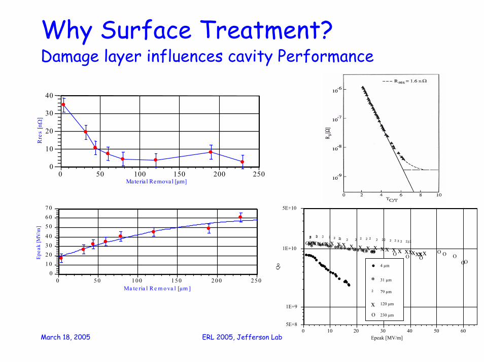
Why Surface Treatment?Damage layer influences cavity Performance
••••••• •••••••• •• •••• •••
* * * * * * * *******************²² ² ² ² ² ² ² ²²²²²²²²²²²²²²²²²
xxxxxxxxxxxxxxxxxxxxxxOO O O O O O O O O O OO O O
OO
5E+8
1E+9
1E+10
5E+10
0 10 20 30 40 50 60
Qo
Epeak [MV/m]
• 4 µm
* 31 µm
² 79 µm
x 120 µm
O 230 µm
•
•
• • • • •
• 0
10
20
30
40
0 50 100 150 200 250
Rre
s [n
Ω]
Ma teria l Removal [µm]
• •
• • •
• •
•
0 1 0 2 0 3 0 4 0 5 0 6 0 7 0
0 5 0 1 0 0 1 5 0 2 0 0 2 5 0
Epe
ak [M
V/m
]
Ma te ria l R e m o va l [µm ]

March 18, 2005 ERL 2005, Jefferson Lab
What is the goal of the surface treatment?Get as close as possible to an ideal surface, achievefundamental limits of the material: very low Rres , Hcrit ~ 185 mT
• Remove the surface damage layer ( > 100 µm)• Defect-free surface• Contamination-free to avoid FE• Smooth for better cleaning, avoid field enhancements…
Frequency Dependence of RbcsTc = 9.2K,l=30 nm, λ=32 nm, ξ=62nm, T=2K
1.0E-10
1.0E-08
2.0E-08
3.0E-08
4.0E-08
5.0E-08
0 500 1000 1500 2000 2500 3000 3500
Frequency [MHz]
Rbc
s[O
hm]
Q = 2.1e10 10
Q =2.7e10
March 18, 2005 ERL 2005, Jefferson Lab
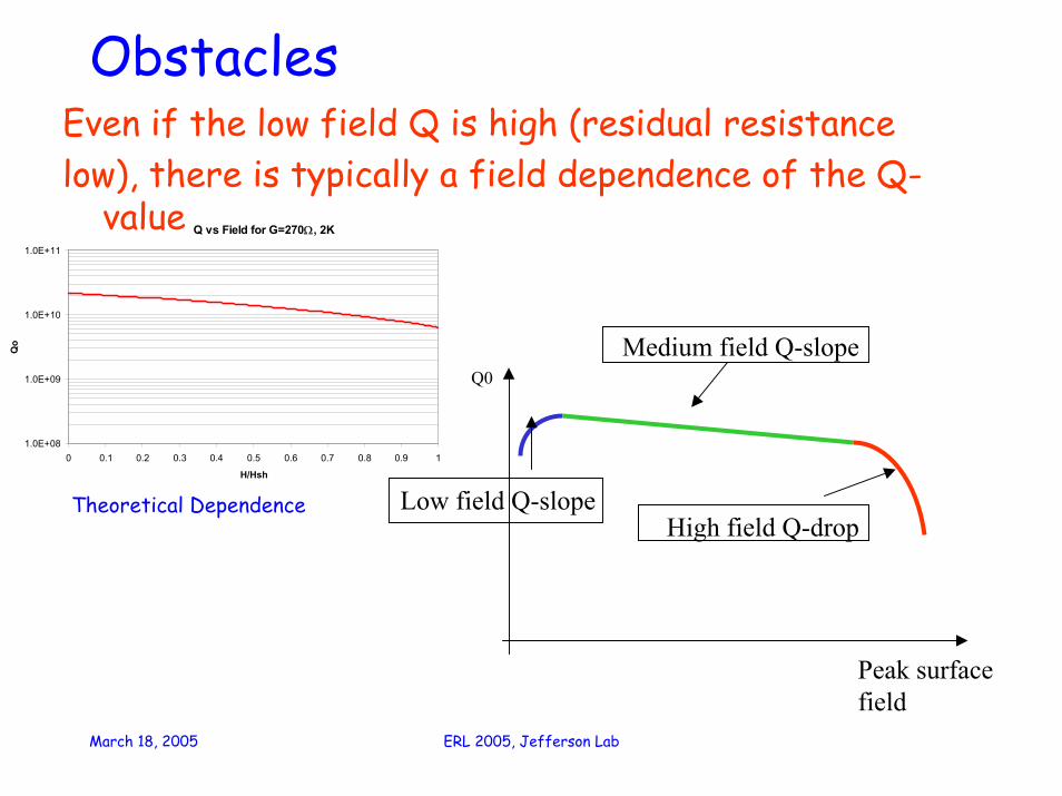
ObstaclesEven if the low field Q is high (residual resistancelow), there is typically a field dependence of the Q-
value
Peak surface field
Q0
Low field Q-slope
Medium field Q-slope
High field Q-drop
Q vs Field for G=270Ω, 2K
1.0E+08
1.0E+09
1.0E+10
1.0E+11
0 0.1 0.2 0.3 0.4 0.5 0.6 0.7 0.8 0.9 1
H/Hsh
Qo
Theoretical Dependence

March 18, 2005 ERL 2005, Jefferson Lab
Q vs Eacc , “Q-drop”• For high RRR niobium often a degradation of the Q value is
observed at gradients (magnetic surface fields) above ~ 20 MV/m (>90 mT)
• “In situ” baking of the cavities at 120C for long periods of time ( ~48 hrs) improves the Q-valuesat lower power and in the Q-drop regime
• The improvement is often more pronounced for EP cavities, but is also observed for BCP’d cavities
• The physics of the Q-drop is still not understoodexplanations range from field enhancements at grain boundaries to effects in the metal-oxide interface or weak links at grain boundaries
• It is clear that oxygen diffusion from the surface into the material plays a role; the depth of the affected zone is several hundred nm

March 18, 2005 ERL 2005, Jefferson Lab
Q vs Eacc , “Q-drop”
Buffered Chemical Polished(1:1:1)
CEBAF Single cell cavity Nb/Ta 1162_33/1162_34 Q0 vs. Eacc,
1.0E+09
1.0E+10
1.0E+11
0 5 10 15 20 25 30 35 40
Eacc [MV/m]
Q0
after baking,120C,40 hrs
1250 C, 100micron,beforebakingTest#4, 300 micron bcp
Quench
Quench
[B.Visentin,SRF2003]
electropilished

March 18, 2005 ERL 2005, Jefferson Lab
Surface Treatment Procedures• Eddy CurrentScanning, Squid Scanning
(successfully used at DESY on TTF cavities)• Degreasing ( ultrasound + soap+water, solvents)• BCP ( HF:HNO3 :H3PO4 as 1:1:1, 1:1:2,1:1:4)
(room temperature or below to avoid excessive hydrogen pick-up)
• Electropolishing (HF/H2SO4 Siemens-KEK-Recipes)• Barrel Polishing• High pressure Ultrapure Water Rinsing• High Temperature Heat Treatment (600C to 1400C for
Hydrogen degassing, Post Purification)• “In-situ” baking ( typically 120C for> 24 hrs)• Alternative Cleaning:CO2 Snow, Megasonic, UV Ozon..

March 18, 2005 ERL 2005, Jefferson Lab
Scanning of Niobium SheetsSuccessfully developed at DESY to pre-screen NbSheets for defects: eddy current, resolution ~ 100 µm
squid, resolution < 50 µm
(W.Singer, X.Singer)

March 18, 2005 ERL 2005, Jefferson Lab

March 18, 2005 ERL 2005, Jefferson Lab
March 18, 2005 ERL 2005, Jefferson Lab
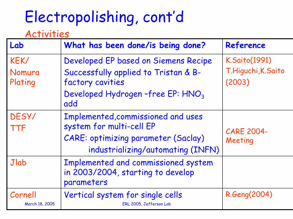
Electropolishing, cont’dActivities
R.Geng(2004)Vertical system for single cellsCornell
Implemented and commissioned system in 2003/2004, starting to develop parameters
Jlab
CARE 2004-Meeting
Implemented,commissioned and uses system for multi-cell EPCARE: optimizing parameter (Saclay)
industrializing/automating (INFN)
DESY/TTF
K.Saito(1991)T.Higuchi,K.Saito(2003)
Developed EP based on Siemens RecipeSuccessfully applied to Tristan & B-factory cavitiesDeveloped Hydrogen –free EP: HNO3add
KEK/Nomura Plating
ReferenceWhat has been done/is being done?Lab

March 18, 2005 ERL 2005, Jefferson Lab
EP- SystemsKEK/Nomura Plating DESY JLab
Cornell
11.03.2005Lutz Lilje DESY -MPY-
INFN

March 18, 2005 ERL 2005, Jefferson Lab
High Pressure Water Rinsing• Universally used as last step in surface preparation• Water: ultrapure, resistivity > 18 MΩcm• Pressure: ~ 100 bar ( 1200 psi)• Nozzle configuration: varying, SS or sapphire• “Scanning”: single or multiple sweeps,
continuous rotation + up/down• Add. HPR after attachment of auxiliary
components

March 18, 2005 ERL 2005, Jefferson Lab
High Pressure Rinse Systems
KEK-System
Jlab HPR Cabinet
DESY-System

March 18, 2005 ERL 2005, Jefferson Lab
High Temperature Heat TreatmentUHV Heat Treatment of Niobium used since the“beginning of times”; nowadays :
• Hydrogen degassing: 600C for 10 hrs at Jlab750 C for 3 hrs at KEK
• Annealing: 800 C, several hrs• Post- Purification: 1200C to 1400C in presence
of a solid state getter, e.g.TiImprovement of RRRLoss of mechanical propertiesgrain growth

March 18, 2005 ERL 2005, Jefferson Lab
Thermal conductivity of samples from the niobium sheets used in the TESLA cavities: before and after the 1400 ºC
heat treatment (RRR = 270 and RRR = 500 respectively)
0
5
10
15
20
25
30
35
0 200 400 600 800
RRR
Eac
c, M
V/m
quench
pow er limit
Eacc versus RRR of TTF cavities
Cavity post purification (solid state gettering)
Post purification of Nb [W.Singer, 2003]
The heat treatment also homogenize the Nb ( reduction of magnetic flux
pinning centers shown by magnetization measurement)

March 18, 2005 ERL 2005, Jefferson Lab
Centrifugal Barrel Polishing(CBP)(1)• Barrel Polishing (“tumbling”) developed at
KEK for smoothening of surfaces/weldsplastic stones, water + abrasive
• Process very slow, by adding motion, removal rate increased 10fold: ~ 44 mm in 8 hrs
• During the process, hydrogen is dissolved in the niobium(“Q-disease”) and needs to be removed by furnace treatment
• Hydrogen-free CBP accomplished by usinga different (hydrogen-free) agent:FC-77(C8F18,C8F16 O) [T.Higuchi,K. Saito SRF 2003]

March 18, 2005 ERL 2005, Jefferson Lab
Centrifugal Barrel Polishing(2)
[T.Higuchi, K. Saito, SRF 2003 ]

March 18, 2005 ERL 2005, Jefferson Lab
CO2 Snow CleaningDeveloped at DESY (D.Reschke) as an alternative toHPR or “in situ” cleaning for modules
• A prototpye system has been fabricated and initial tests have been made on samples and on single cell cavities
• optimization of process necessary (cleaning effect; avoidance of condensation, mass flow)
• A production system is under construction and will be completed some time in the autumn of 2005

March 18, 2005 ERL 2005, Jefferson Lab
Preliminary Tests- successful cleaning of Nb samples
=> investigation of field emission properties + reduction of particlescollaboration with G. Müller, University of Wuppertal, Germany; see SRF Workshop 2001
Optical microscope images before (left) and after (right) dry-ice cleaning of ansample intentionally contaminated with Fe and Cu particles (500x mag)
[L.Lilje, CARE Meeting Nov. 2004, DESY]

March 18, 2005 ERL 2005, Jefferson Lab
Cavity Tests on Mono-cells- dedicated nozzle system for cavity cleaning developed [L.Lilje, CARE
Meeting Nov. 2004, DESY]

March 18, 2005 ERL 2005, Jefferson Lab
First Results of Cavity Tests- Q-values up to 4,0 ·1010 at 1.8 K => no surface contamination
- gradients up to 33 MV/m => field emission is limiting effect
[L.Lilje, CARE Meeting Nov. 2004, DESY]
Q(E)-performance of two monocells before (black) and after (red) dry-ice cleaning

March 18, 2005 ERL 2005, Jefferson Lab
Single Crystal BCPProvides very smooth surfaces as measured by A.Wu, Jlab
RMS: 1274 nm fine grain bcp27 nm single crystal bcp251 nm fine grain ep
RMS 1274 nm
RMS 27 nm

March 18, 2005 ERL 2005, Jefferson Lab
Procedures: general remarks• “Enemies” of good cavity performance are:
insufficient material removal, defects and contamination ( field emission)
• All procedures need to deal with these problems and the most difficult is control of contamination
• Level of contamination is different in different labs and depends on facilities, design, auxiliary parts, hardware ( e.g. bolts, gaskets..) and people
• Optimum procedures have to be developed for each lab and project

March 18, 2005 ERL 2005, Jefferson Lab
“Standard” Treatment Procedures(1)BCP , TTF Module 1-5, SNS• Outside bcp(> 20 µm), inside bcp ( 80-100µm), clean water rinsing• Hydrogen degassing ( 600C-SNS, 800C TTF)• Rinsing in UPW, post-purification with Ti, 1400C• BCP to remove Ti surface layer: 80 µm inside, 40 µm outside, UPW
rinse• Re-tuning
20 µm inside bcp, UHP water rinse
HPR, drying in class 10, open, 12 hrs
Assembly of auxiliary parts
Vacuum leak check of flange connections
Venting, dismount pumping flange
1. + 2. HPR(check of particle#, TOC…)
Installation of antenna for VTA test
No VTA test of bare cavity for SNS
March 18, 2005 ERL 2005, Jefferson Lab
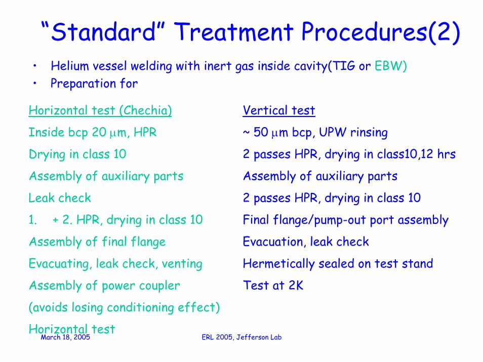
“Standard” Treatment Procedures(2)• Helium vessel welding with inert gas inside cavity(TIG or EBW)• Preparation for
Horizontal test (Chechia)
Inside bcp 20 µm, HPR
Drying in class 10
Assembly of auxiliary parts
Leak check
1. + 2. HPR, drying in class 10
Assembly of final flange
Evacuating, leak check, venting
Assembly of power coupler
(avoids losing conditioning effect)
Horizontal test
Vertical test
~ 50 µm bcp, UPW rinsing
2 passes HPR, drying in class10,12 hrs
Assembly of auxiliary parts
2 passes HPR, drying in class 10
Final flange/pump-out port assembly
Evacuation, leak check
Hermetically sealed on test stand
Test at 2K

March 18, 2005 ERL 2005, Jefferson Lab
“Standard” Treatment Procedures(3)After qualification of cavity with He-vessel
Cleaning for string assembly
(“dirty” class 10000 class 10)
Venting of cavity in class 10
Assembly of gate valves, magnets..
“on the job” cleaning of bolted beam pipe flanges necessary
Final leak check
Venting for transportation to installation in cryostat
assembly
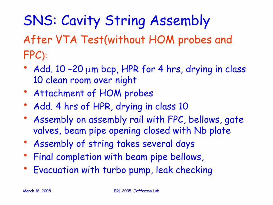
After VTA Test(without HOM probes and FPC):•Add. 10 –20 µm bcp, HPR for 4 hrs, drying in class 10 clean room over night•Attachment of HOM probes•Add. 4 hrs of HPR, drying in class 10•Assembly on assembly rail with FPC, bellows, gate valves, beam pipe opening closed with Nb plate•Assembly of string takes several days•Final completion with beam pipe bellows, •Evacuation with turbo pump, leak checking

March 18, 2005 ERL 2005, Jefferson Lab
String Assembly
The inter-cavity connection is done in class 10 cleanrooms

March 18, 2005 ERL 2005, Jefferson Lab
ModulesSNS Medium Beta Cavity String

March 18, 2005 ERL 2005, Jefferson Lab
Recipes

March 18, 2005 ERL 2005, Jefferson Lab
Recipes-KEK

March 18, 2005 ERL 2005, Jefferson Lab
SNS- Modules
Gradient at Qo = 5 x 10⁹
0
5
10
15
20
0 5 10 15 20CMTF Data (MV/m)
VTA
Dat
a (M
V/m
)Medium β Cavities

March 18, 2005 ERL 2005, Jefferson Lab
Qo at Operating Gradient (10.2 MV/m)
1.E+09
1.E+10
1.E+11
1.E+09 1.E+10 1.E+11
CMTF Data (Qo)
VTA
Dat
a (Q
o)Medium β Cavities

March 18, 2005 ERL 2005, Jefferson Lab
Onset of Field Emission
0
5
10
15
20
0 5 10 15 20CMTF Data (MV/m)
VTA
Dat
a (M
V/m
)Medium β Cavities

March 18, 2005 ERL 2005, Jefferson Lab
Gradient at Qo = 5 x 10⁹
0
5
10
15
20
25
0 5 10 15 20 25CMTF Data (MV/m)
VTA
Dat
a (M
V/m
)High β Cavities

March 18, 2005 ERL 2005, Jefferson Lab
SNS Cavities
0
5
10
15
20
25
Oct-02
Dec-02
Feb-03
Apr-03
Jun-03
Aug-03
Oct-03
Dec-03
Feb-04
Apr-04
Jun-04
Aug-04
Oct-04
Date
Gra
dien
t (M
V/m
)Medium betaHigh beta
Gradient at Qo = 5 x 10⁹

March 18, 2005 ERL 2005, Jefferson Lab
SNS Cavities
0
5
10
15
20
25
Oct-02
Dec-02
Feb-03
Apr-03
Jun-03 Aug-03
Oct-03
Dec-03
Feb-04
Apr-04
Jun-04 Aug-04
Oct-04
Date
Gra
dien
t (M
V/m
)Medium betaHigh beta
Onset of Radiation
March 18, 2005 ERL 2005, Jefferson Lab
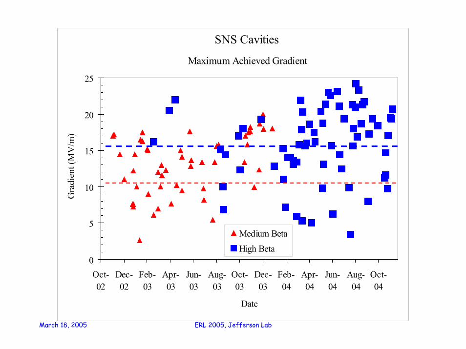
SNS Cavities
0
5
10
15
20
25
Oct-02
Dec-02
Feb-03
Apr-03
Jun-03
Aug-03
Oct-03
Dec-03
Feb-04
Apr-04
Jun-04
Aug-04
Oct-04
Date
Gra
dien
t (M
V/m
)
Medium BetaHigh Beta
Maximum Achieved Gradient

March 18, 2005 ERL 2005, Jefferson Lab
SNS Cavities
1.0E+08
1.0E+09
1.0E+10
1.0E+11
Oct-02
Dec-02
Feb-03
Apr-03
Jun-03
Aug-03
Oct-03
Dec-03
Feb-04
Apr-04
Jun-04
Aug-04
Oct-04
Date
QoQo at Gradient Specification

March 18, 2005 ERL 2005, Jefferson Lab
The TTF Linac‘s Accelerating Cavities
0
5
10
15
20
25
30
35
0 1 2 3 4
Production Series
<Eac
c > [M
V/m
]
The First Three Production Series
(without electro-polished cavities)
TESLA 500 23.4 MV/m
Approx. 80 cavities were produced in three production series. Gradient and gradient spread improved a lot.
Nine accelerator modules with 8 cavities each were assembled.
58 different cavities were used for the module assembly. Some cavities were used for a second assembly.
Series 1 18.7 ± 7.0Series 2 22.8 ± 3.1Series 3 26.0 ± 1.9

March 18, 2005 ERL 2005, Jefferson Lab
DESY/TTFVertical tests

March 18, 2005 ERL 2005, Jefferson Lab
Electro-Polishing becomes State-of-the-Art Surface Preparation Technique and will be used for the XFEL
AC70 AC72
AC73 AC78
AC76
Electro-polished Cavities Measured in Vertical Test
Accelerating Gradient (MV/m)
Unl
oade
d Q
ualit
y Fa
ctor
109
1010
1011
0 10 20 30 40

March 18, 2005 ERL 2005, Jefferson Lab
Performance of Accelerator Module 5A State-of-the-art module
• cryogenic type III
• latest coupler generation
• BCP cavities
In single cavity measurements 6 out of 8 cavities reach 30 MV/m!
Equal power feeding <Eacc> = 25 MV/m

March 18, 2005 ERL 2005, Jefferson Lab
Dark Current MeasurementDark Current vs. RF phase with respect to neighbouring cavities is just as expected
(max min) over pi/2
The on-axis dark current was measured for modules ACC4 / ACC5.
Only one cavity in module ACC5 produced a mentionable dark current.
• captured dark current could be measured at the exit of ACC5
• there was no d.c. from this cavity at the entrance of ACC4
• the d.c. decreased as a function of time
after module commissioning (August 2003) 100 nA at 16 MV/m increasing by a factor 10 for each 4.4 MV/m gradient stepi.e. approx. 10 µA at 25 MV/m
May 4th100 nA at 20 MV/m increasing by a factor 10 for each 3.7 MV/m gradient step, i.e. 1.2 µA at 25 MV/m
September 22ndafter a few weeks on-time at 20 – 25 MV/m250 nA at 25 MV/m
• detuning of cavity no. 6 left over an integrated dark currentof the order of 20 to 25 nA at 25 MV/m average gradient
Reminder:
The TESLA limit is defined by additional cryogenic losses:
The captured d.c. has to stay below 50 nA per cavity. (see TESLA Report 2003-10).

March 18, 2005 ERL 2005, Jefferson Lab
Jlab Upgrade: Renasence ModuleHG Cavities for Renascence - VTA Performance
1.0E+09
1.0E+10
1.0E+11
0 5 10 15 20 25
Gradient (MV/m)
Q0
12 GeV Project SpecHG 31 WattsLL 31 WattsOC 31 WattsHG002HG003HG004HG005HG006HG001
T= 2.07
HG 31 W
LL 31 W
OC 31 W
11/8/04 cer
5 LL cavities, 3 HG cavities
LL Cavities for Renascence - VTA Performance
1.0E+09
1.0E+10
1.0E+11
0 5 10 15 20 25
Gradient (MV/m)
Q0
12 GeV Project SpecHG 31 WattsLL 31 WattsOC 31 WattsLL001LL002LL003LL004
T= 2.07
HG 31 W
LL 31 W
OC 31 W
12/2/04 cer

March 18, 2005 ERL 2005, Jefferson Lab
AcknowledgementsMany colleagues provided me with informations forthis talk and I used slides from presentations byseveral colleagues:C. Reece,Jlab, J. Ozelis, Jlab.H. Whitehead, JlabA.Matheisen, DESY,L. Lilje, DESY,H. Weise, DESY,D. Reschke, DESYhttp://adweb.desy.de/~weise/:Operational Experience with the TTF Linac
Das Europäische XFEL Projekthttp://www.aps.anl.gov/conferences/RFSC-Limits/Presentations.htmlD.Reschke,”Field Emission Overview ; Cleanliness and Processing”http://lcdev.kek.jp/ILCWS/WG5.phpA.Matheisen,”Cavity fabrication and Processing”http://www-bd.fnal.gov/niobium/program.htmlW.Singer,”Material Properties of High Purity Niobium for SC Cavities”

March 18, 2005 ERL 2005, Jefferson Lab
Back-up Slides
March 18, 2005 ERL 2005, Jefferson Lab
SNS: Cavity String AssemblyAfter VTA Test(without HOM probes andFPC):• Add. 10 –20 µm bcp, HPR for 4 hrs, drying in class
10 clean room over night• Attachment of HOM probes• Add. 4 hrs of HPR, drying in class 10• Assembly on assembly rail with FPC, bellows, gate
valves, beam pipe opening closed with Nb plate• Assembly of string takes several days• Final completion with beam pipe bellows, • Evacuation with turbo pump, leak checking

March 18, 2005 ERL 2005, Jefferson Lab
35 MV/m for 800 GeV c.m.Electrolytic Polishing at DESYInfrastructure for 9-cell cavities was commissioned with single cell cavities.
First 9-cell cavities were successfully treated.

March 18, 2005 ERL 2005, Jefferson Lab
ElectropolishingAbsorption of Hydrogen avoided by applying apotential to the sample and adding an oxidizer(HNO3) to the EP solution [S.Higuchi, K.Saito SRF2003]
March 18, 2005 ERL 2005, Jefferson Lab
1E+09
1E+10
1E+11
0 10 20 30 40Eacc [MV/m]
Q0
AC55 AC56AC57 AC58AC59 AC60AC61 AC62AC63 AC64AC65 AC66AC67 AC68AC69 AC79
1011
109
1010
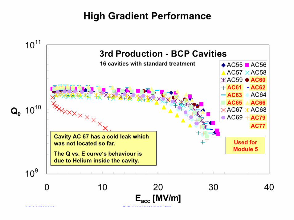
3rd Production - BCP Cavities
Cavity AC 67 has a cold leak which was not located so far.
The Q vs. E curve‘s behaviour is due to Helium inside the cavity.
16 cavities with standard treatment
AC61AC63AC65
AC60AC62
AC66
AC79AC77
Used for Module 5
High Gradient Performance

March 18, 2005 ERL 2005, Jefferson Lab
35 MV/m for 800 GeV c.m.
First electro-polished single cell cavities
BCP Surface (1µm roughness)
BCP Surface (1µm roughness)
0.5 mm
EP Surface (0.1µm roughness)
0.5 mm
Electro-polishing (EP) instead of the standard chemical polishing (BCP) eliminates grain boundary steps. The development of this technique is strongly connected to work done by Kenji Saito (KEK).Gradients of 40 MV/m at Q values above 1010 are now reliably achieved in single cells at KEK, DESY/CERN and TJNAF.The highest gradient achieved was 42 MV/m.


