For first teaching from September 2016 For first award of AS level in Summer 2017 For first award of A level in Summer 2018 Subject Code: 1210 CCEA GCE Specimen Assessment Material for Physics GCE
Transcript
For first teaching from September 2016For first award of AS level in Summer 2017For first award of A level in Summer 2018Subject Code: 1210
CCEA GCE SpecimenAssessment Material for
Physics
GCE
ForewordCCEA has developed new specifications which comply with criteria for GCE qualifications. The specimen assessment materials accompanying new specifications are provided to give centres guidance on the structure and character of the planned assessments in advance of the first assessment. It is intended that the specimen assessment materials contained in this booklet will help teachers and students to understand, as fully as possible, the markers’ expectations of candidates’ responses to the types of tasks and questions set at GCE level. These specimen assessment materials should be used in conjunction with CCEA’s GCE Physics specification.
There is no necessity for the questions to follow the sequence of topics in the specification.
BLANK PAGE
GCE PhysicsSpecimen Assessment Materials
Contents
Specimen Papers 3
Assessment Unit AS 1: Forces, Energy and Electricity 3Assessment Unit AS 2: Waves, Photons and Astronomy 25Assessment Unit AS 3A: Practical Techniques and Data Analysis 45Assessment Unit AS 3B: Practical Techniques and Data Analysis 51Assessment Unit A2 1: Deformation of Solids, Thermal Physics, Circular Motion,
Oscillations and Atomic and Nuclear Physics59
Assessment Unit A2 2: Fields, Capacitors and Particle Physics 77Assessment Unit A2 3A: Practical Techniques and Data Analysis 99Assessment Unit A2 3B: Practical Techniques and Data Analysis 111
Data and Formulae Sheets 123
Assessment Unit AS: Data and Formulae Sheet 123Assessment Unit A2: Data and Formulae Sheet 125
Apparatus and Materials Lists and Confidential Instructions 129
Assessment Unit AS 3A: Practical Techniques and Data Analysis 129Assessment Unit A2 3A: Practical Techniques and Data Analysis 135
Mark Schemes 141
General Marking Instructions 143Assessment Unit AS 1: Forces, Energy and Electricity 147Assessment Unit AS 2: Waves, Photons and Astronomy 153Assessment Unit AS 3A: Practical Techniques and Data Analysis 159Assessment Unit AS 3B: Practical Techniques and Data Analysis 163Assessment Unit A2 1: Deformation of Solids, Thermal Physics, Circular Motion,
Oscillations and Atomic and Nuclear Physics167
Assessment Unit A2 2: Fields, Capacitors and Particle Physics 173Assessment Unit A2 3A: Practical Techniques and Data Analysis 181Assessment Unit A2 3B: Practical Techniques and Data Analysis 185
You may download further copies of this publication from www.ccea.org.uk
SPECIMEN PAPERS
DIVIDER FRONT
SPECIMEN PAPERS
DIVIDER BACK
TIME1 hour 45 minutes
INSTRUCTIONS TO CANDIDATESWrite your Centre Number and Candidate Number in the spaces provided at the top of this page.Answer all nine questions.Write your answers in the spaces provided in this question paper.
INFORMATION FOR CANDIDATESThe total mark for this paper is 100.Figures in brackets printed down the right-hand side of pages indicate the marks awarded to each question, or part question.Your attention is drawn to the Data Formulae Sheet which is inside this question paper.You may use an electronic calculator.
For Examiner’suse only
Question Number Marks
1 2 3 4 5 6 7 8 9
TotalMarks
Physics
Assessment Unit AS 1assessing
Forces, Energy and Electricity
[CODE]SPECIMEN PAPER
Centre Number
Candidate Number
ADVANCED SUBSIDIARYGeneral Certificate of Education
2017
3
4
BLANK PAGE
Examiner Only
Marks Re-mark
5 [Turn over
Answer all questions
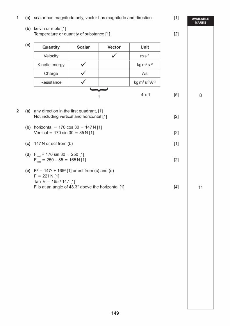
1 (a) What is the difference between a scalar and a vector quantity?
[1]
(b) The kilogram (kg), metre (m), second (s) and ampere (A) are four of the SI base units.
Name another SI base unit and state the physical quantity to which it refers.
Unit:
Physical quantity: [2]
(c) Five physical quantities are listed in Table 1.1 By inserting a tick in the appropriate column, show whether each is a scalar or a vector.
In the last column, write the unit of the quantity, expressed as a suitable combination of two or more of the SI base units kg, m, s and A. The first line of the table has been completed as an example.
Table 1.1
Quantity Scalar Vector Unit
Momentum ü kg m s–1
Velocity
Kinetic energy
Charge
Resistance
[5]
Examiner Only
Marks Re-mark
6
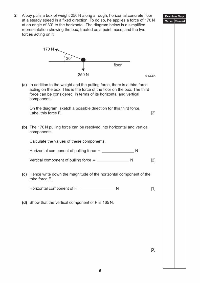
2 A boy pulls a box of weight 250 N along a rough, horizontal concrete floor at a steady speed in a fixed direction. To do so, he applies a force of 170 N at an angle of 30° to the horizontal. The diagram below is a simplified representation showing the box, treated as a point mass, and the two forces acting on it.
(a) In addition to the weight and the pulling force, there is a third force acting on the box. This is the force of the floor on the box. The third force can be considered in terms of its horizontal and vertical components.
On the diagram, sketch a possible direction for this third force. Label this force F. [2]
(b) The 170 N pulling force can be resolved into horizontal and vertical components.
Calculate the values of these components.
Horizontal component of pulling force N
Vertical component of pulling force N [2]
(c) Hence write down the magnitude of the horizontal component of the third force F.
Horizontal component of F N [1]
(d) Show that the vertical component of F is 165 N.
[2]
170 N
250 N
floor30˚
Examiner Only
Marks Re-mark
7 [Turn over
(e) Use your answer to (c) and the information in (d) to find the magnitude and exact direction of F.
Magnitude of F N
Direction of F [4]
Examiner Only
Marks Re-mark
8
3 Two cars A and B are both travelling at 21 m s–1, in the same direction, along a straight road. The distance between them at t 0 seconds is 48 m. At this time the driver of the rear car (B) decides to overtake the car ahead.
The driver of Car B accelerates uniformly at 2 m s–2 until reaching a speed of 27 m s–1. Then the driver continues at this speed until he is 48 m ahead of the other car.
(i) How long does it take the driver in the overtaking car (Car B) to accelerate their car from 21 m s–2 to 27 m s–2?
Time s [2]
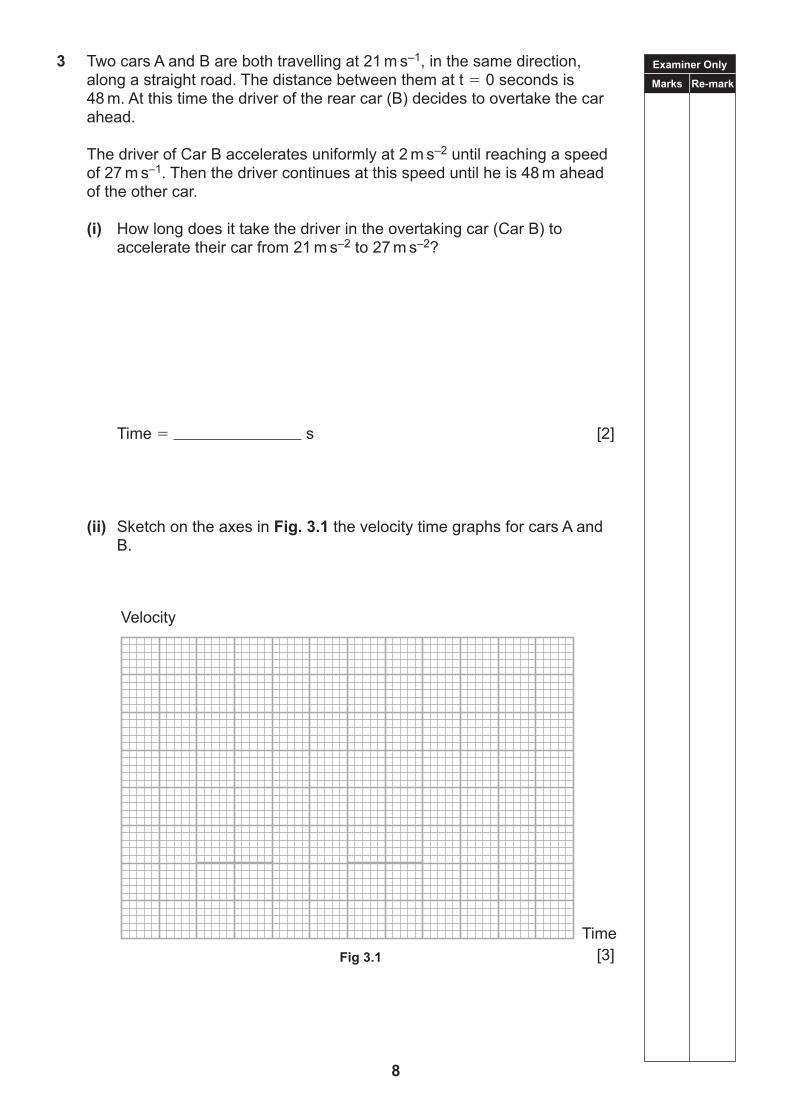
(ii) Sketch on the axes in Fig. 3.1 the velocity time graphs for cars A and B.
[3]
Velocity
Time
Fig. 3.1Fig 3.1
Examiner Only
Marks Re-mark
9 [Turn over
(iii) Calculate the time taken for the overtaking car to be 48 m ahead of the other car.
Time s [5]
(iv) How far does the overtaking car travel between t 0 and the time when it is 48 m ahead of the other car?
Distance m [2]
(v) Give one assumption for the car being overtaken (car A) that you have made in answering this question.
[1]
Examiner Only
Marks Re-mark
10
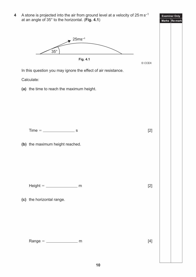
4 A stone is projected into the air from ground level at a velocity of 25 m s–1 at an angle of 35° to the horizontal. (Fig. 4.1)
In this question you may ignore the effect of air resistance.
(d) the magnitude and direction of the velocity 0.60 s after projection.
Velocity:
Magnitude m s–1
Direction (relative to the horizontal direction) [4]
Examiner Only
Marks Re-mark
12
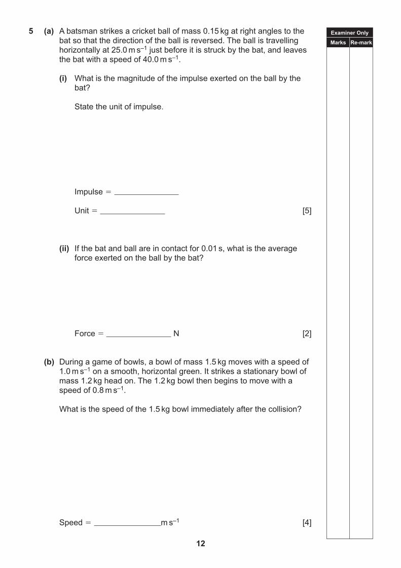
5 (a) A batsman strikes a cricket ball of mass 0.15 kg at right angles to the bat so that the direction of the ball is reversed. The ball is travelling horizontally at 25.0 m s–1 just before it is struck by the bat, and leaves the bat with a speed of 40.0 m s–1.
(i) What is the magnitude of the impulse exerted on the ball by the bat?
State the unit of impulse.
Impulse
Unit [5]
(ii) If the bat and ball are in contact for 0.01 s, what is the average force exerted on the ball by the bat?
Force N [2]
(b) During a game of bowls, a bowl of mass 1.5 kg moves with a speed of 1.0 m s–1 on a smooth, horizontal green. It strikes a stationary bowl of mass 1.2 kg head on. The 1.2 kg bowl then begins to move with a speed of 0.8 m s–1.
What is the speed of the 1.5 kg bowl immediately after the collision?
Speed m s–1 [4]
Examiner Only
Marks Re-mark
13 [Turn over
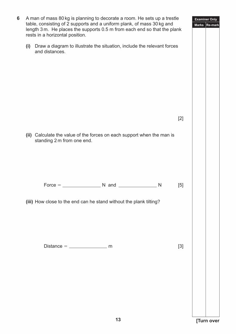
6 A man of mass 80 kg is planning to decorate a room. He sets up a trestle table, consisting of 2 supports and a uniform plank, of mass 30 kg and length 3 m. He places the supports 0.5 m from each end so that the plank rests in a horizontal position.
(i) Draw a diagram to illustrate the situation, include the relevant forces and distances.
[2]
(ii) Calculate the value of the forces on each support when the man is standing 2 m from one end.
Force N and N [5]
(iii) How close to the end can he stand without the plank tilting?
Distance m [3]
Examiner Only
Marks Re-mark
14
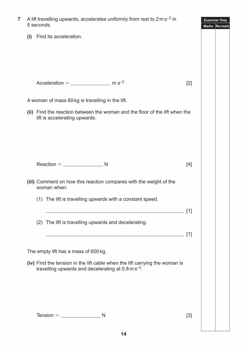
7 A lift travelling upwards, accelerates uniformly from rest to 2 m s–2 in 5 seconds.
(i) Find its acceleration.
Acceleration m s–2 [2]
A woman of mass 60 kg is travelling in the lift.
(ii) Find the reaction between the woman and the floor of the lift when the lift is accelerating upwards.
Reaction N [4]
(iii) Comment on how this reaction compares with the weight of the woman when:
(1) The lift is travelling upwards with a constant speed.
[1]
(2) The lift is travelling upwards and decelerating.
[1]
The empty lift has a mass of 600 kg.
(iv) Find the tension in the lift cable when the lift carrying the woman is travelling upwards and decelerating at 0.8 m s–2.
Tension N [3]
15 [Turn over
BLANK PAGE
(Questions continue overleaf)
Examiner Only
Marks Re-mark
16
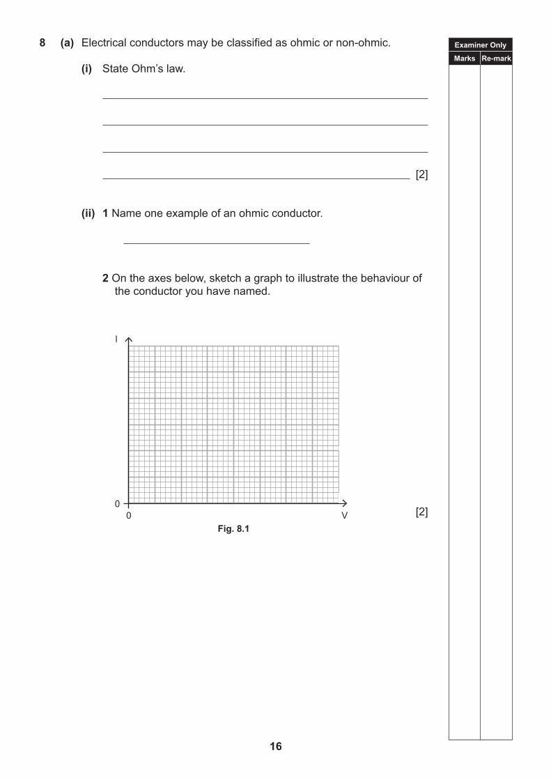
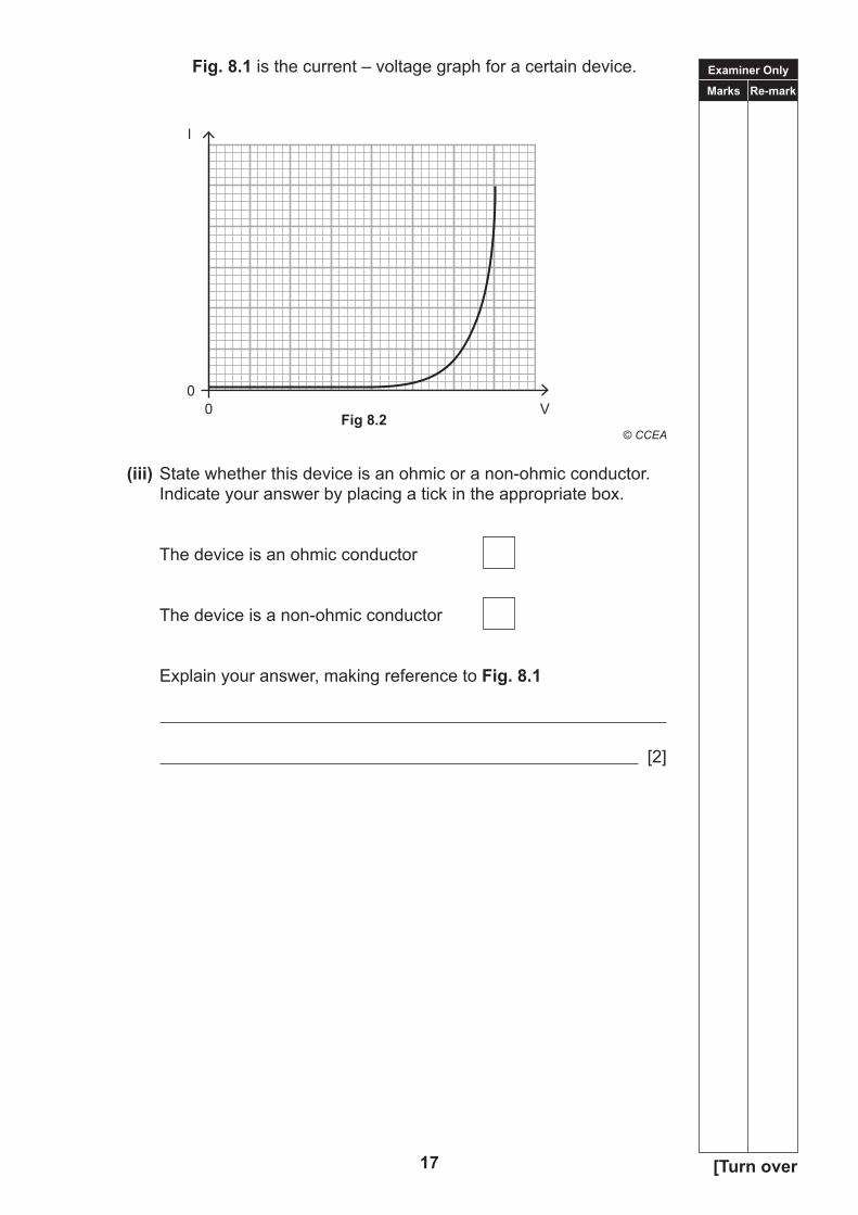
8 (a) Electrical conductors may be classified as ohmic or non-ohmic.
(i) State Ohm’s law.
[2]
(ii) 1 Name one example of an ohmic conductor.
2 On the axes below, sketch a graph to illustrate the behaviour of the conductor you have named.
[2]0
0
l
V
Fig. 8.1Fig. 8.1
Examiner Only
Marks Re-mark
17 [Turn over
Fig. 8.1 is the current – voltage graph for a certain device.
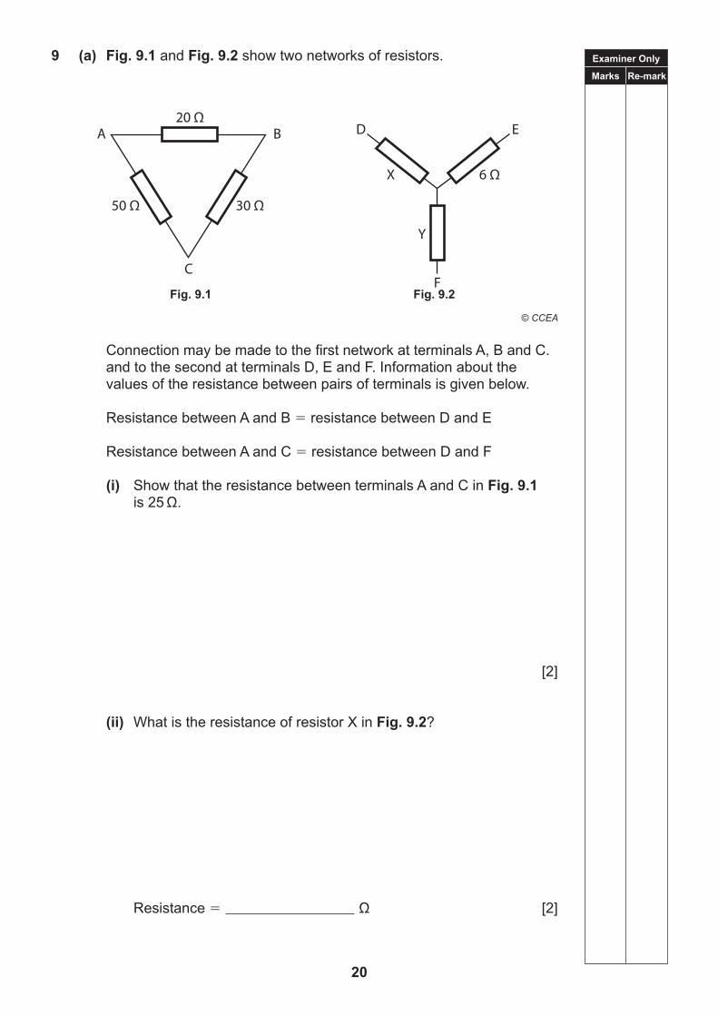
Connection may be made to the first network at terminals A, B and C. and to the second at terminals D, E and F. Information about the values of the resistance between pairs of terminals is given below.
Resistance between A and B resistance between D and E
Resistance between A and C resistance between D and F
(i) Show that the resistance between terminals A and C in Fig. 9.1 is 25 Ω.
[2]
(ii) What is the resistance of resistor X in Fig. 9.2?
Resistance Ω [2]
20 Ω
30 Ω50 Ω
C
A B
Fig. 9.1
D E
Fig. 9.2
X 6 Ω
Y
FFig. 9.1 Fig. 9.2
Examiner Only
Marks Re-mark
21 [Turn over
(iii) Hence obtain the resistance of resistor Y in Fig. 9.2.
Resistance Ω [1]
(b) Your data and formulae sheet includes the following formula for a potential divider.
Vout
R1 Vin Equation 9.1 (R1 R2)
In the space below, draw a simple potential divider circuit. Label appropriate parts of your diagram R1, R2, Vout and Vin to correspond with these symbols in Equation 9.1.
[3]
Examiner Only
Marks Re-mark
22
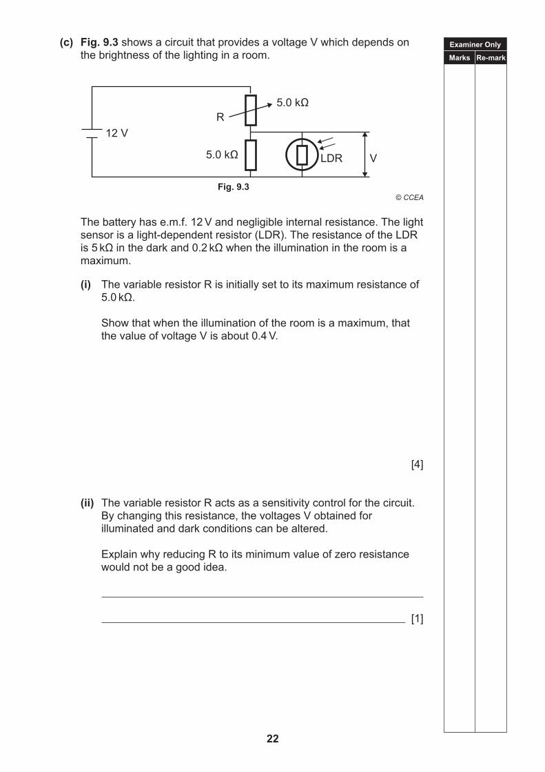
(c) Fig. 9.3 shows a circuit that provides a voltage V which depends on the brightness of the lighting in a room.
The battery has e.m.f. 12 V and negligible internal resistance. The light
sensor is a light-dependent resistor (LDR). The resistance of the LDR is 5 kΩ in the dark and 0.2 kΩ when the illumination in the room is a maximum.
(i) The variable resistor R is initially set to its maximum resistance of 5.0 kΩ.
Show that when the illumination of the room is a maximum, that the value of voltage V is about 0.4 V.
[4]
(ii) The variable resistor R acts as a sensitivity control for the circuit. By changing this resistance, the voltages V obtained for illuminated and dark conditions can be altered.
Explain why reducing R to its minimum value of zero resistance would not be a good idea.
[1]
12 VR
5.0 kΩ LDR
5.0 kΩ
V
Fig. 9.3Fig. 9.3
THIS IS THE END OF THE QUESTION PAPER
23
24
BLANK PAGE
25
TIME1 hour 45 minutes
INSTRUCTIONS TO CANDIDATESWrite your Centre Number and Candidate Number in the spaces provided at the top of this page.Answer all nine questions.Write your answers in the spaces provided in this question paper.
INFORMATION FOR CANDIDATESThe total mark for this paper is 100.Figures in brackets printed down the right-hand side of pages indicate the marks awarded to each question or part question.Your attention is drawn to the Data Formulae Sheet which is inside this question paper.You may use an electronic calculator.
For Examiner’suse only
Question Number Marks
1 2 3 4 5 6 7 8 9
TotalMarks
Physics
Assessment Unit AS 2assessing
Waves, Photons and Astronomy
[CODE]SPECIMEN PAPER
Centre Number
Candidate Number
ADVANCED SUBSIDIARYGeneral Certificate of Education
2017
Examiner Only
Marks Re-mark
26
Answer all questions.
1 (a) Satellites orbiting the Earth provide television signals for satellite dish aerials on Earth. One satellite transmits vertically-polarised electromagnetic waves at a frequency of 11.3 GHz.
(i) Explain what is meant by a polarised wave.
[1]
(ii) Calculate the wavelength of the transmission.
Wavelength m [3]
(iii) State the region of the electromagnetic spectrum in which the transmission lies.
[1]
(b) (i) Explain what is meant by a longitudinal wave.
[1]
(ii) Name an example of a longitudinal wave.
[1]
Examiner Only
Marks Re-mark
27 [Turn over
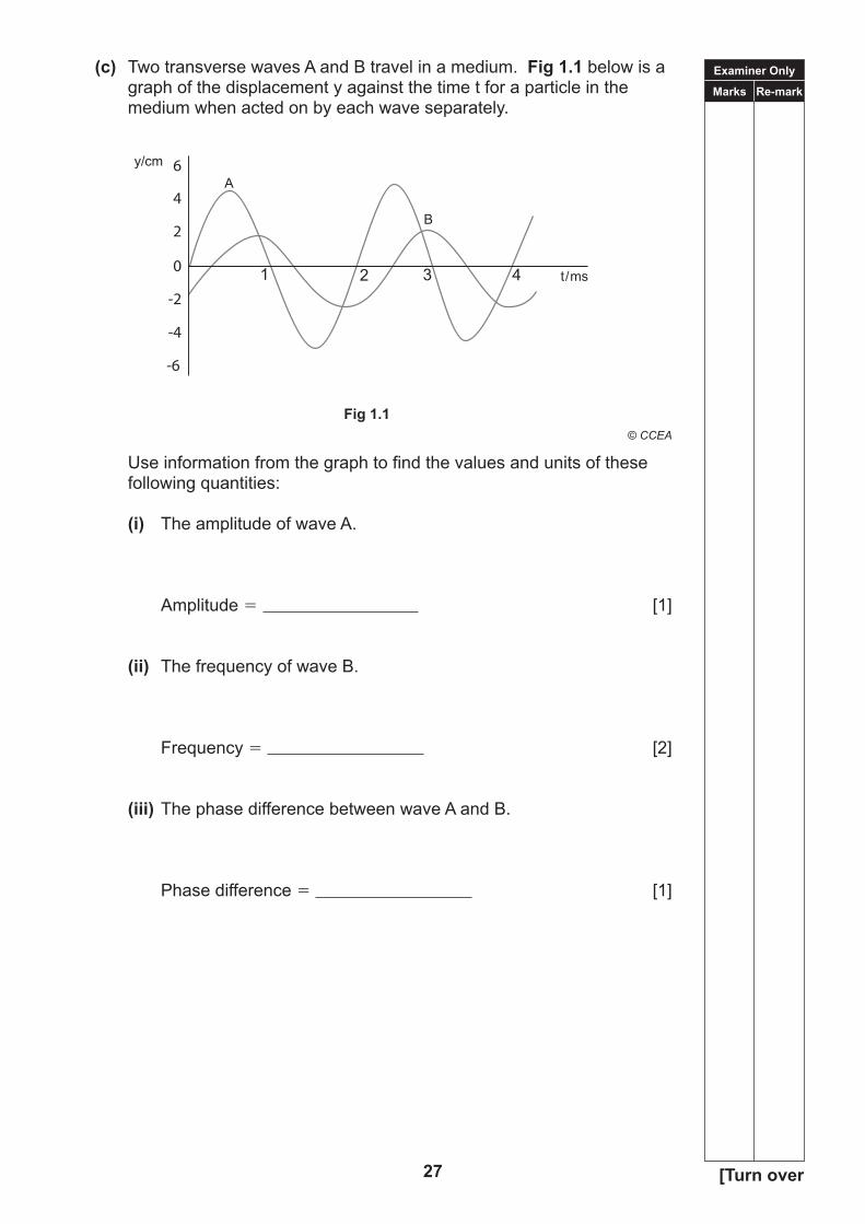
(c) Two transverse waves A and B travel in a medium. Fig 1.1 below is a graph of the displacement y against the time t for a particle in the medium when acted on by each wave separately.
Use information from the graph to find the values and units of these following quantities:
(i) The amplitude of wave A.
Amplitude [1]
(ii) The frequency of wave B.
Frequency [2]
(iii) The phase difference between wave A and B.
Phase difference [1]
6
4
2
0
-2
-4
-6
y/cm
t/ms
A
B
1 2 3 4
Examiner Only
Marks Re-mark
28
2 (a) Describe an experiment to verify the lense equation for a converging lens of known focal length.
Your description should include:
(i) a labelled diagram showing the arrangement of the apparatus used;
(ii) the procedure used and what measurements are recorded; (iii) an explanation of how the results obtained should be used to
verify the equation. (i) Labelled diagram
[2] (ii) Procedure
[4]
(iii) Explanation
[3]
Examiner Only
Marks Re-mark
29 [Turn over
(b) A converging lens of focal length 250 mm forms a sharp image of an illuminated object on a screen, so that the linear magnification is 50.
Without moving the object, the positions of the lens and screen are then altered so that a sharp image is again formed on the screen, but this time with a linear magnification of 100.
Through what distance, and in what direction relative to the object, has the lens been moved?
Distance mm Direction [6]
Examiner Only
Marks Re-mark
30
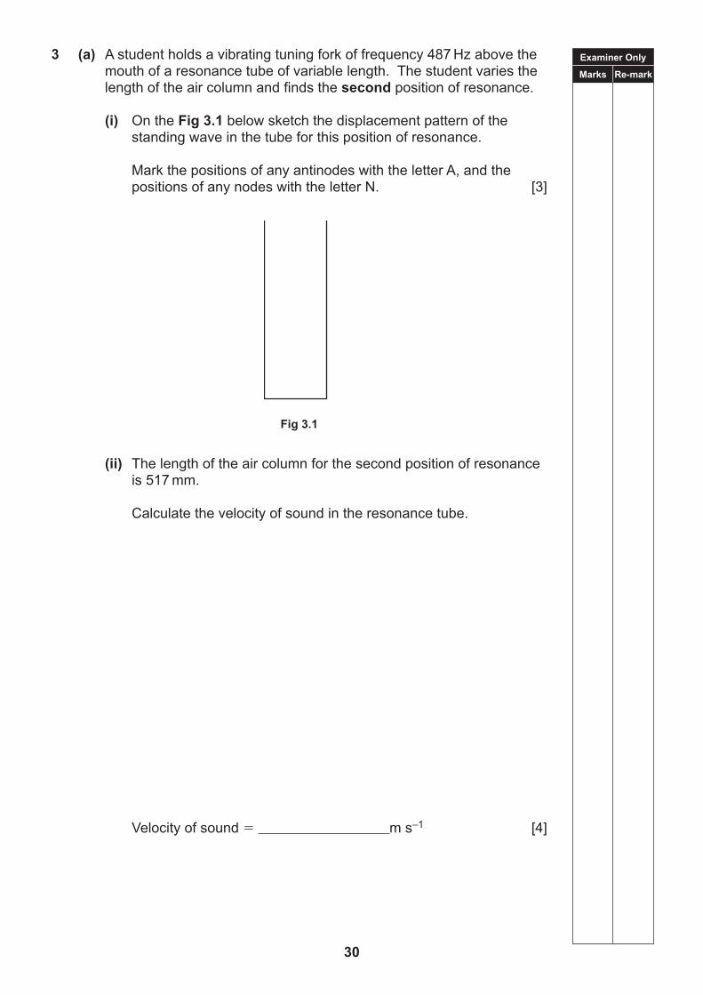
3 (a) A student holds a vibrating tuning fork of frequency 487 Hz above the mouth of a resonance tube of variable length. The student varies the length of the air column and finds the second position of resonance.
(i) On the Fig 3.1 below sketch the displacement pattern of the standing wave in the tube for this position of resonance.
Mark the positions of any antinodes with the letter A, and the positions of any nodes with the letter N. [3]
Fig 3.1
(ii) The length of the air column for the second position of resonance is 517 mm.
Calculate the velocity of sound in the resonance tube.
Velocity of sound m s–1 [4]
Fig 3.1
Examiner Only
Marks Re-mark
31 [Turn over
(b) Standing waves can also be generated in a resonance tube using a loudspeaker as a sound source.
(i) What other equipment is needed?
[1]
(ii) When an air column of fixed length 307 mm is used, resonance is found to occur only at frequencies of 282 Hz, 845 Hz and 1392 Hz, in the frequency range from zero to 1500 Hz.
Use this information to calculate an average value for the velocity of sound in this air column.
Velocity of sound m s–1 [4]
Examiner Only
Marks Re-mark
32
4 (a) A double slit system is illuminated by monochromatic light coming from a single slit placed in front of a light source. Interference fringes may be seen on a screen placed some distance beyond the slits.
(i) Explain, with the aid of a labelled sketch, how both diffraction and interference effects are involved in obtaining the observed fringes.
[3]
(ii) Suggest three changes in the experiment, each of which would result in an increase in the fringe separation y.
1
2
3 [3]
Examiner Only
Marks Re-mark
33 [Turn over
(b) A grating has 500 lines per mm and is illuminated normally by light of wavelength 589 nm.
(i) Determine the angle between the first-order maximum and second-order maximum.
Angle ° [5]
(ii) Find the highest order of diffraction which could be obtained.
Highest order [3]
Examiner Only
Marks Re-mark
34
5 The emission spectrum of hydrogen in distant galaxies was observed.
(a) Explain why the lines in the spectrum from distant galaxies have a longer wavelength than the lines in the spectrum observed from a source in the laboratory.
[1]
(b) A particular line in the hydrogen spectrum has a wavelength of 656 nm.
When the same line is observed in the Messier 87(M87) galaxy, its wavelength is 659 nm.
(i) Calculate the value of the cosmological parameter, z, for M87 using these data.
z [2]
(ii) Use the cosmological parameter, z, to calculate the rate at which the distance between the galaxies is increasing.
Rate of increase km s–1 [2]
(iii) Calculate the distance between The Milky Way and M87.
Distance km [2]
Examiner Only
Marks Re-mark
35 [Turn over
(c) Use the Hubble constant to estimate the age of the universe. Take 1 year as 3.15 107 s.
Age of universe years [3]
Examiner Only
Marks Re-mark
36
6 (a) (i) Define the power of a lens.
[1]
(ii) Name the SI unit of lens power.
[1]
(b) The far point of a person viewing objects is at 80 cm from the eye.
(i) What is this defect of vision called?
[1]
(ii) Suggest a possible cause for this condition.
[1]
(iii) What type of lens is needed to correct this defect?
[1]
(iv) Calculate the power of the spectacle lens needed to change this person’s far point to the normal far point position.
Power SI units [3]
Examiner Only
Marks Re-mark
37 [Turn over
(c) Without spectacles, the near point of the person in (b) is at 18 cm from his eye. The person now uses the spectacles in (b)(iv).
Calculate the new distance of the person’s near point from his eye.
Near point distance cm [3]
Examiner Only
Marks Re-mark
38
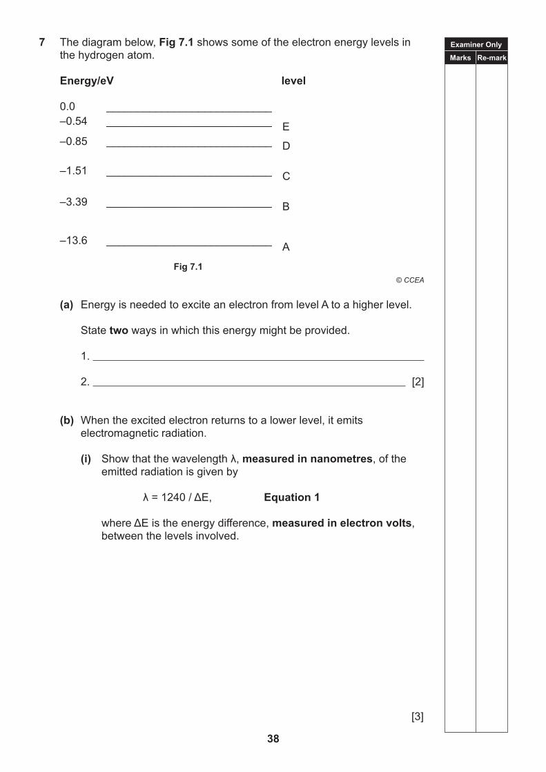
7 The diagram below, Fig 7.1 shows some of the electron energy levels in the hydrogen atom.
(a) Energy is needed to excite an electron from level A to a higher level.
State two ways in which this energy might be provided.
1. 2. [2]
(b) When the excited electron returns to a lower level, it emits electromagnetic radiation.
(i) Showthatthewavelengthλ,measured in nanometres, of the emitted radiation is given by
λ=1240/ΔE, Equation 1 whereΔEistheenergydifference,measured in electron volts, between the levels involved.
[3]
E
D
C
B
A
Examiner Only
Marks Re-mark
39 [Turn over
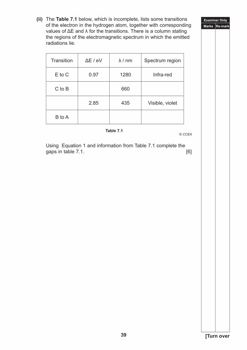
(ii) The Table 7.1 below, which is incomplete, lists some transitions of the electron in the hydrogen atom, together with corresponding valuesofΔEandλforthetransitions.Thereisacolumnstatingthe regions of the electromagnetic spectrum in which the emitted radiations lie.
Using Equation 1 and information from Table 7.1 complete the gaps in table 7.1. [6]
Examiner Only
Marks Re-mark
40
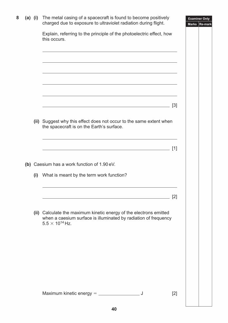
8 (a) (i) The metal casing of a spacecraft is found to become positively charged due to exposure to ultraviolet radiation during flight. Explain, referring to the principle of the photoelectric effect, how this occurs.
[3]
(ii) Suggest why this effect does not occur to the same extent when the spacecraft is on the Earth’s surface.
[1]
(b) Caesium has a work function of 1.90 eV.
(i) What is meant by the term work function?
[2]
(ii) Calculate the maximum kinetic energy of the electrons emitted when a caesium surface is illuminated by radiation of frequency 5.5 1014 Hz.
Maximum kinetic energy J [2]
Examiner Only
Marks Re-mark
41 [Turn over
Examiner OnlyMarks Remark
(iii) With the aid of a calculation, explain whether or not photoelectric emission would occur if the caesium surface were illuminated with radiation of frequency 4.0 1014 Hz.
[2]
Examiner Only
Marks Re-mark
42
9 (a) State the meaning of a de Broglie wavelength.
[1]
(b) An electron accelerated from rest through a certain potential difference has a de Broglie wavelength of 1.2 10–10 m when it reaches its final speed.
(i) Calculate this final speed.
Speed m s–1 [2]
(ii) Calculate the potential difference applied.
Potential difference V [3]
THIS IS THE END OF THE QUESTION PAPER
43
44
BLANK PAGE
TIME1 hour.
Write your Centre Number and Candidate Number in the spaces provided at the top of this page.Write your answers in the spaces provided in this question paper.Answer all four questions.
The total mark for this paper is 40.Figures in brackets printed down the right-hand side of pages indicate the marks awarded to each question or part question.
INSTRUCTIONS TO CANDIDATES
INFORMATION FOR CANDIDATES
Centre Number
Candidate Number
ADVANCED SUBSIDIARYGeneral Certificate of Education
2017
For Examiner’suse only
Question Number Marks
1 2 3 4
TotalMarks
Physics
Assessment Unit AS 3Aassessing
Practical Techniques and Data Analysis
[CODE]SPECIMEN PAPER
45
Examiner Only
Marks Re-mark
46
Answer all questions
1 Determine the resistance of a carbon film resistor.
(a) Consider the available apparatus and draw the circuit diagram you will use to obtain the data from which the resistance of the component marked R can be determined.
[2]
(b) Set up the circuit and in the space below tabulate sufficient results from which you can obtain a reliable value for the resistance of component R.
[6]
(c) Use your results to determine a value for the resistance of component R
Resistance _______________ [2]
Examiner Only
Marks Re-mark
47 [Turn over
2 Verify that the acceleration produced in an object is proportional to the applied force.
(a) Consider the experimental arrangement set up for you.
Outline how you will use it to obtain data from which acceleration is proportional to the force can be verified.
Describe how you can ensure the accelerated mass remains constant.
[2]
(b) Tabulate sufficient results from which you verify acceleration is proportional to the force.
[6]
(c) Use your results to verify acceleration is proportional to the force.
[2]
Examiner Only
Marks Re-mark
48
3 Determining the refractive index of a transparent rectangular block.
(a) Consider the available apparatus and draw a labelled diagram of the experimental arrangement you will use to obtain the data from which the refractive index can be determined.
Outline the procedure for taking valid results.
[2]
(b) Set up the apparatus and in the space below tabulate sufficient results from which you can determine the refractive index of the block.
[6]
(c) Use your results to determine the refractive index of the block.
Refractive index _______________ [2]
Examiner Only
Marks Re-mark
49 [Turn over
4 Determine the density of the material of a metallic column using the most appropriate measuring devices from the apparatus provided.
(a) State the apparatus selected and the quantity being measured in each case.
[2]
(b) Record all measurements in an appropriate table.
[6]
(c) Use your results to determine the density of the material, stating the unit.
Density _______________ Unit _______________ [2]
THIS IS THE END OF THE QUESTION PAPER
50
TIME1 hour.
INSTRUCTIONS TO CANDIDATESWrite your Centre Number and Candidate Number in the spaces provided at the top of this page.Write your answers in the spaces provided in this question paper.Answer all five questions.
INFORMATION FOR CANDIDATESThe total mark for this paper is 50.Figures in brackets printed down the right-hand side of pages indicate the marks awarded to each question or part question.
For Examiner’suse only
Question Number Marks
1 2 3 4 5
TotalMarks
Physics
Assessment Unit AS 3Bassessing
Practical Techniques and Data Analysis
[CODE]SPECIMEN PAPER
Centre Number
Candidate Number
ADVANCED SUBSIDIARYGeneral Certificate of Education
2017
51
Examiner Only
Marks Re-mark
52
Answer all questions
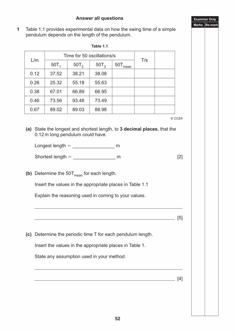
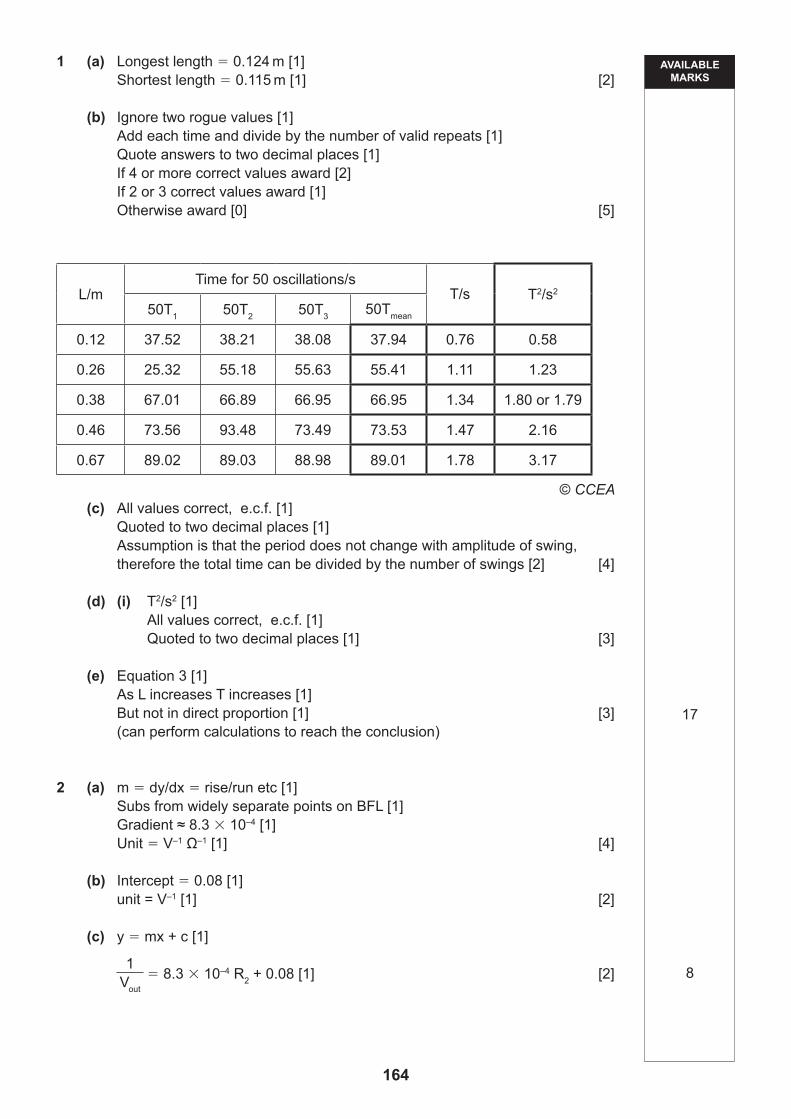
1 Table 1.1 provides experimental data on how the swing time of a simple pendulum depends on the length of the pendulum.
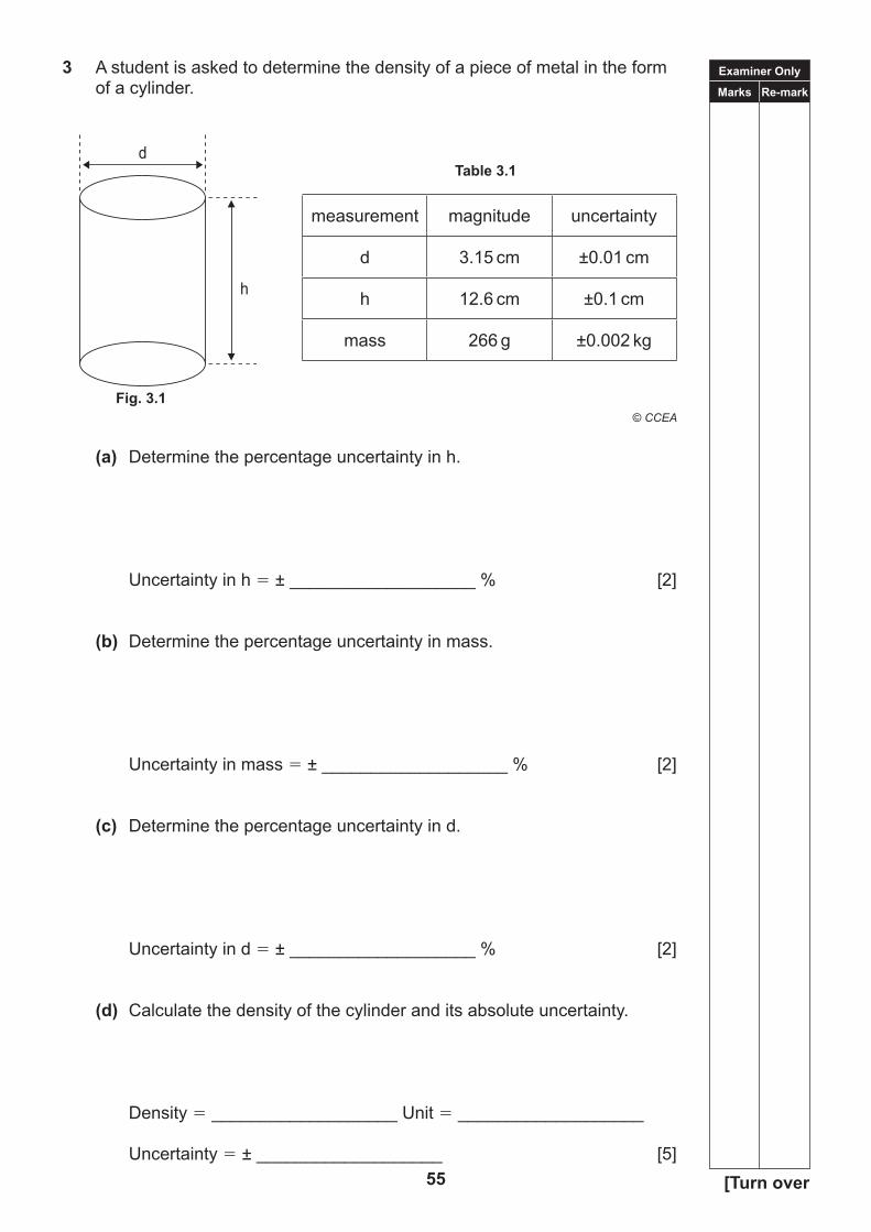
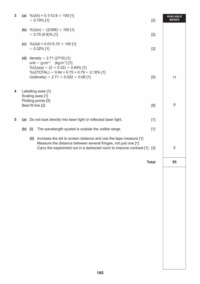
(d) Calculate the density of the cylinder and its absolute uncertainty.
Density ___________________ Unit ___________________
Uncertainty ± ___________________ [5]
measurement magnitude uncertainty
d 3.15 cm ±0.01 cm
h 12.6 cm ±0.1 cm
mass 266 g ±0.002 kg
d
h
Fig 3.1Fig. 3.1
Examiner Only
Marks Re-mark
56
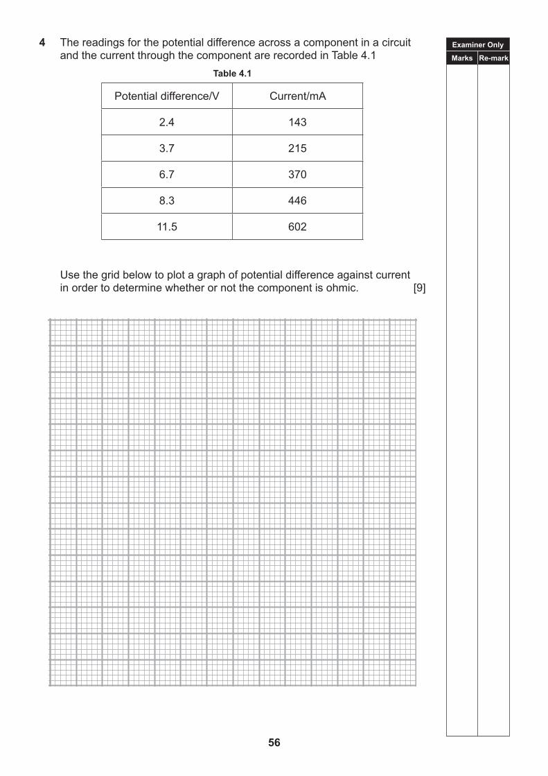
4 The readings for the potential difference across a component in a circuit and the current through the component are recorded in Table 4.1
Table 4.1
Potential difference/V Current/mA
2.4 143
3.7 215
6.7 370
8.3 446
11.5 602
Use the grid below to plot a graph of potential difference against current in order to determine whether or not the component is ohmic. [9]
Examiner Only
Marks Re-mark
57 [Turn over
5 A group of students is asked to perform a Young two slit experiment to find the wavelength of the light from a helium-neon laser. They are provided with the laser, a 5 m tape measure, a ruler, a screen and a double slit with a 0.3 mm spacing.
(a) The students are reminded by the teacher of an important safety point when using a laser.
What is the safety instruction?
[1]
(b) The students quickly perform the experiment and show the following results to the teacher.
a 0.3 mm d 30 cm y 1 mm λ 1000 nm
The teacher tells the students that it is obvious they have made a mistake or are very inaccurate.
(i) How is the teacher able to come to this conclusion?
[1]
The students state that they had difficulty in measuring the distance between one bright fringe and the next.
(ii) State three modifications to the method used which would improve the accuracy of the result.
1
2
3 [3]
THIS IS THE END OF THE QUESTION PAPER
58
59
TIME2 hours
INSTRUCTIONS TO CANDIDATESWrite your Centre Number and Candidate Number in the spaces provided at the top of this page.Write your answers in the spaces provided in this question paper.Answer all eight questions.
INFORMATION FOR CANDIDATESThe total mark for this paper is 100.Figures in brackets printed down the right-hand side of pages indicate the marks awarded to each question or part question.Quality of written communication will be assessed in Question 8(c).Your attention is drawn to the Data and Formulae Sheet which is inside this question paper.You may also use an electronic calculator.
For Examiner’suse only
Question Number Marks
12345678
TotalMarks
Physics
Assessment Unit A2 1assessing
Momentum, Thermal Physics, Circular Motion, Oscillations and Atomic and Nuclear Physics
[CODE]SPECIMEN PAPER
Centre Number
Candidate Number
ADVANCEDGeneral Certificate of Education
2018
Examiner Only
Marks Re-mark
60
Answer all questions
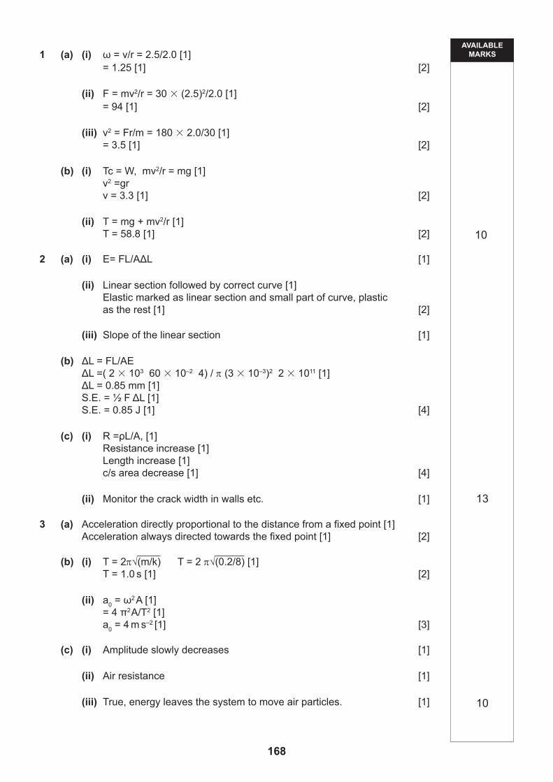
1 (a) A girl of mass 30 kg sits at the edge of a merry-go-round of radius 2.0 m. A boy turns the merry-go-round by gripping its edge and running round so that a point on the edge moves with a steady speed of 2.5 ms–1.
(i) Calculate the angular velocity of the roundabout.
Angular velocity rad s–1 [2]
(ii) Calculate the magnitude of the minimum force required to prevent the girl from sliding off the roundabout.
Force N [2]
(iii) The maximum centripetal force that the girl can provide is 180 N. Trying to make the girl slide off, the boy runs faster.
At what speed must he make a point on the edge of the merry-go-round move in order to make the girl slide off?
Speed m s–1 [2]
Examiner Only
Marks Re-mark
61 [Turn over
(b) It is possible for a person to swing a bucket, containing water, in a vertical circle, without spilling water. The radius of the circle involved may be taken to be 1.1 m.
(i) Calculate the minimum linear speed of the bucket which will prevent water from spilling out at the top of the swing.
Speed m s–1 [2]
(ii) Assuming that this minimum linear speed is constant throughout the swing, find the maximum force of tension in the person’s arm if the mass of the bucket is 1.0 kg and it contains 2.0 kg of water.
Tension N [2]
Examiner Only
Marks Re-mark
62
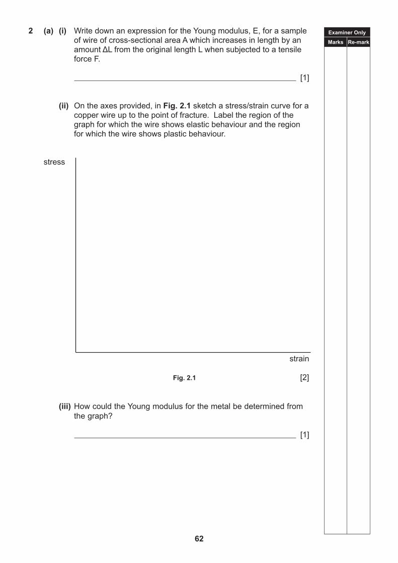
2 (a) (i) Write down an expression for the Young modulus, E, for a sample of wire of cross-sectional area A which increases in length by an amount ΔL from the original length L when subjected to a tensile force F.
[1]
(ii) On the axes provided, in Fig. 2.1 sketch a stress/strain curve for a copper wire up to the point of fracture. Label the region of the graph for which the wire shows elastic behaviour and the region for which the wire shows plastic behaviour.
stress
strain
Fig. 2.1 [2]
(iii) How could the Young modulus for the metal be determined from
the graph?
[1]
Examiner Only
Marks Re-mark
63 [Turn over
(b) A metal rod of diameter 3.00 mm and length 60.0 cm is subjected to a tensile force of 2.00 kN.
If the Young modulus for the material of the rod is 2.00 1011 Pa, calculate the potential energy in the strained rod.
Energy J [4]
(c) (i) Write down an expression for the electrical resistance of a conductor of length L and cross-sectional area A, made from metal of resistivity ρ.
State and explain what you would expect to happen to the resistance of the conductor if it were subjected to a tensile stress.
[4]
(ii) This variation of resistance is the principle of one type of strain gauge.
Suggest one practical application of such a device.
[1]
Examiner Only
Marks Re-mark
64
3 (a) A body moves with simple harmonic motion.
Describe the acceleration of the body.
[2]
(b) A body of mass 0.20 kg hangs from the end of a suspended helical spring. The spring has a force constant k value of 8.0 N m–1. When the body is raised 0.10 m above its equilibrium position and is then released, it executes simple harmonic motion.
(i) Find the period of the oscillation.
Period s [2]
(ii) Calculate the acceleration of the body at the lower extremity of its first oscillation.
Acceleration m s–2 [3]
Examiner Only
Marks Re-mark
65 [Turn over
(c) In practice, an oscillating system such as a pendulum is lightly damped.
(i) What experimental evidence shows that a pendulum is lightly damped?
[1]
(ii) What is the cause of the damping?
[1]
(iii) “Because of damping, the total energy of the oscillating pendulum is not conserved.”
State, with a reason, whether this statement is true or false.
[1]
Examiner Only
Marks Re-mark
66
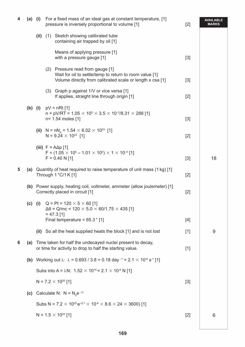
4 (a) (i) A student states the law relating pressure and volume for an ideal gas as follows “For an ideal gas, pressure is inversely proportional to volume.”
This statement is incomplete in two respects. Rewrite the statement correctly.
[2]
(ii) You are asked to carry out an experiment to investigate whether the law applies to air.
(1) Sketch a labelled diagram of the apparatus you would use.
[3]
(2) Using the apparatus you have sketched in (1), describe how you would obtain measurements of the pressure and volume of the sample of air under investigation.
Pressure
Volume
[3]
(3) State the graph you would plot using your results and how you would use it to conclude whether or not the law applies.
[2]
Examiner Only
Marks Re-mark
67 [Turn over
(b) A party balloon is inflated with helium at a temperature of 15 °C, and has a volume 3.5 10–2 m3. The pressure of the gas inside the balloon is 1.05 105 Pa.
(i) Calculate the number of moles of gas inside the balloon.
Number of moles [3]
(ii) How many helium atoms are inside the balloon?
Number of helium atoms [2]
(iii) The pressure of air outside the balloon is 1.01 105 Pa.
Calculate the net force due to the air and gas pressures on an area of one square centimetre of the material of the balloon.
Force N [3]
Examiner Only
Marks Re-mark
68
5 (a) Define the specific heat capacity of a material.
[2]
(b) It is required to determine the specific heat capacity of copper, using an electrical method.
Draw a labelled diagram of the circuit you would use.
[2]
(c) A block of material, of mass 1.75 kg, is heated for 5.00 minutes using an immersion heater of power 120W. The block is completely lagged. The initial temperature of the block is 18.0 °C. The specific heat capacity of the material of the block is 435 J kg–1 °C–1.
(i) Calculate the final temperature of the block.
Temperature °C [4]
(ii) What is the purpose of having the block completely lagged?
[1]
Examiner Only
Marks Re-mark
69 [Turn over
6 Radon 222 has a half-life of 3.8 days
(a) Define half-life.
[1]
(b) Calculate the initial number of radon 222 nuclei present in the sample if its initial activity is 1.52 × 10¹⁵ Bq.
Initial number of nuclei [3]
(c) Hence calculate the number of radon 222 nuclei present after a period of 8.6 days.
Number of radon 222 nuclei = [2]
Examiner Only
Marks Re-mark
70
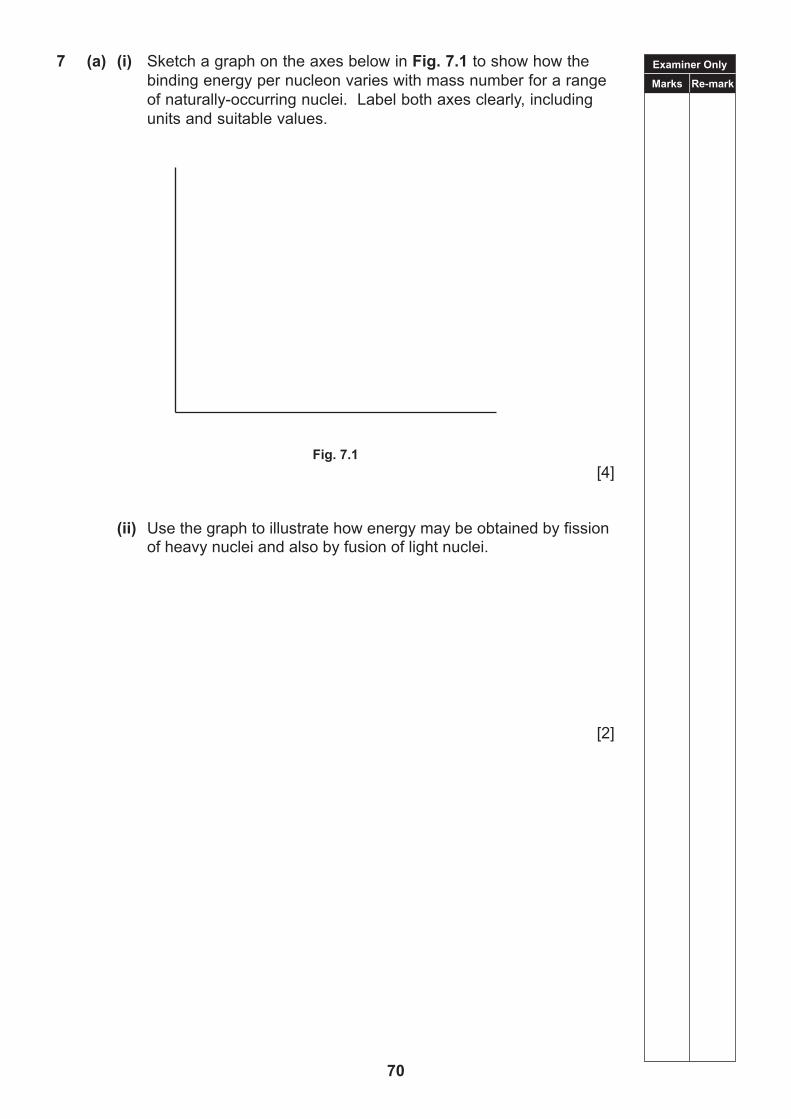
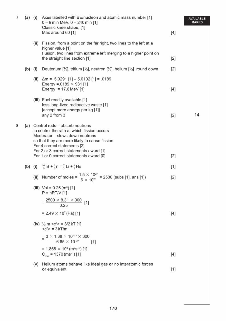
7 (a) (i) Sketch a graph on the axes below in Fig. 7.1 to show how the binding energy per nucleon varies with mass number for a range of naturally-occurring nuclei. Label both axes clearly, including units and suitable values.
Fig. 7.1 [4]
(ii) Use the graph to illustrate how energy may be obtained by fission of heavy nuclei and also by fusion of light nuclei.
[2]
Examiner Only
Marks Re-mark
71 [Turn over
(b) The following fusion reaction, using two isotopes of hydrogen, is possible:
2 3 1 4 1 H 1 H → 0 n 2 He energy
(i) Give the commonly used names of the four particles described by the symbols in this equation.
[2]
(ii) Using the data below, calculate the energy (in MeV) produced per fusion reaction.
Nuclear masses:
1 0 n 1.0087 u
2 1 H 2.0136 u
3 1 H 3.0155 u
4 2 He 4.0015 u
Energy MeV [4]
(iii) The energy obtained per fusion reaction, is only about one-tenth of the energy produced per fission of a heavy nucleus.
In view of this give two reasons why a working fusion reactor might nevertheless be considered a “better” energy source than a fission reactor.
[2]
Examiner Only
Marks Re-mark
72
8 (a) Describe fully the function of the control rods and the moderator in a nuclear fission reactor.
Control rods
Moderator
[2]
Many fission reactors use boron control rods. Each rod of boron is sealed inside a casing. When the boron nucleus 5 B absorbs a fast neutron it immediately decays to produce a lithium (Li) nucleus and an alpha particle. As a result, helium gas is produced which occupies the spaces between the atoms of the rod.
Each cubic metre of the control rod can absorb 1.5 1027 neutrons before it has to be replaced.
(b) (i) Write down the equation for the nuclear reaction which takes place inside the boron control rod. Include the nucleon and proton numbers.
[1]
(ii) Calculate how many moles of helium are trapped in each cubic metre of the control rod when 1.5 x 1027 neutrons are absorbed.
Number of moles of helium [2]
10
Examiner Only
Marks Re-mark
73 [Turn over
The boron atoms themselves occupy 75% of the total volume of the control rod.
Just before the rod is replaced the temperature of the gas inside the casing is 27°C.
(iii) Calculate the pressure of the helium gas inside the casing just before the rod is replaced.
Pressure Pa [4]
(iv) The mass of each helium atom is 6.65 10–27 kg.
Calculate the root mean square (r.m.s) speed of the trapped helium atoms inside the casing just before the control rod is about to be replaced.
r.m.s. speed m s–1 [4]
(v) State one assumption you have made when calculating the rms speed of the helium atoms in part (iv).
[1]
Examiner Only
Marks Re-mark
74
Quality of written communication will be assessed in this question.
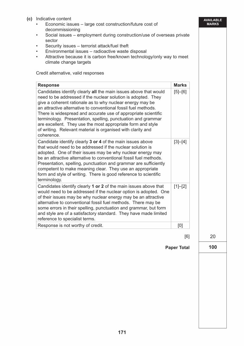
(c) The use of nuclear power is seen as one possible solution to a future energy crisis.
What issues would need to be addressed if this solution is adopted and why is nuclear energy an attractive alternative to conventional fossil fuel methods?
[6]
THIS IS THE END OF THE QUESTION PAPER
75
THIS IS THE END OF THE QUESTION PAPER
76
TIME2 hours.
Write your Centre Number and Candidate Number in the spaces provided at the top of this page.Answer all eight questions.Write your answers in the spaces provided in this question paper.
The total mark for this paper is 100.Quality of written communication will be assessed in Question 5 (a) (i).Figures in brackets printed down the right-hand side of pages indicate the marks awarded to each question or part question.Your attention is drawn to the Data and Formulae Sheet which is inside this question paper.You may use an electronic calculator.
INSTRUCTIONS TO CANDIDATES
INFORMATION FOR CANDIDATES
For Examiner’suse only
Question Number Marks
1 2 3 4 5 6 7 8
TotalMarks
Physics
Assessment Unit A2 2assessing
Fields, Capacitors and Particle Physics
[CODE]SPECIMEN PAPER
Centre Number
Candidate Number
ADVANCEDGeneral Certificate of Education
2018
77
78
BLANK PAGE
Examiner Only
Marks Re-mark
79 [Turn over
Answer all questions
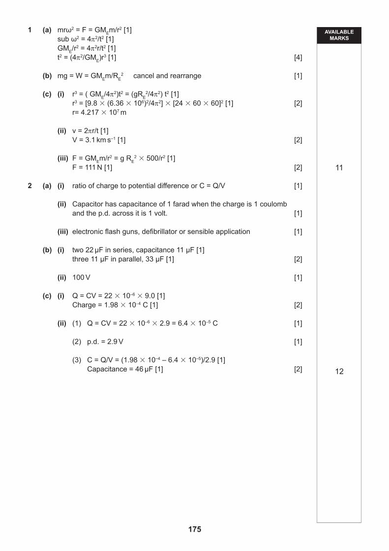
1 (a) A certain satellite orbits the earth with a period t in a circular path of radius r. Show that the relationship
t2 r3
is consistent with Newton’s law of gravitation. Obtain an expression for the constant of proportionality from your analysis.
[4]
(b) By considering the weight of a body on the surface of the earth, show that gRE
2 GME, where G is the gravitational constant and ME and RE are the mass and radius of the earth respectively.
[1]
Examiner Only
Marks Re-mark
80
(c) A satellite of mass 500 kg has a circular orbit about the earth with a period of one day.
(i) Show that the radius of this orbit is 4.22 107 m. (The mean radius of the earth RE = 6.36 × 10⁶ m)
[2]
(ii) What is the orbital speed of the satellite?
Speed km s–1 [2]
(iii) Find the value of the gravitational force between the earth and the satellite.
Force N [2]
Examiner Only
Marks Re-mark
81 [Turn over
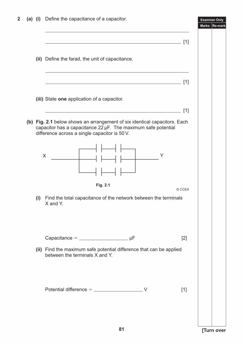
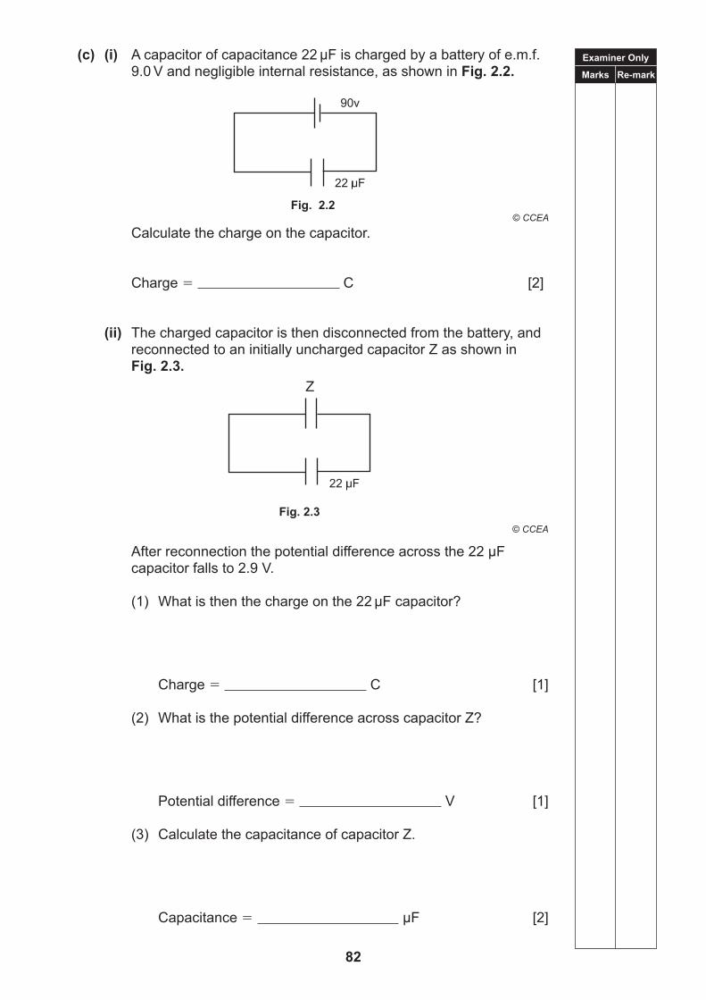
2 (a) (i) Define the capacitance of a capacitor.
[1]
(ii) Define the farad, the unit of capacitance.
[1]
(iii) State one application of a capacitor.
[1]
(b) Fig. 2.1 below shows an arrangement of six identical capacitors. Each capacitor has a capacitance 22 µF. The maximum safe potential difference across a single capacitor is 50 V.
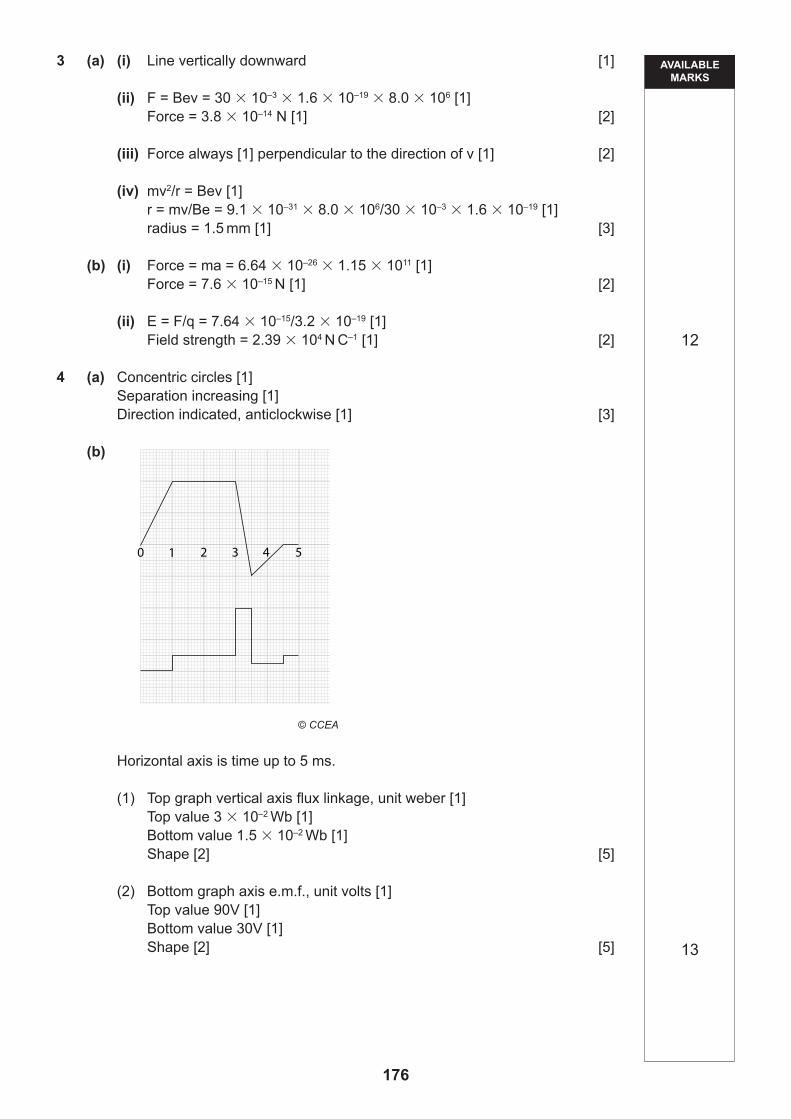
(b) A magnet is moved relative to a long solenoid of 500 turns and cross sectional area 1.5 10–2 m2 creating a magnetic field within the solenoid.
The magnet is moved so that the magnetic flux density varied as follows:
(i) the flux density increases uniformly from zero to 4.0 10–3 T in 1.0 ms; (ii) the flux density remains constant for 2 ms; (iii) the flux density changes uniformly to 2.0 10–3 T in the opposite direction in 0.5 ms; (iv) the flux density reduces uniformly to zero in 1.0 ms; and (v) the flux density remains zero for 0.5 ms.
draw, to scale, two graphs;
(1) representing the variation of flux linkage through the coil with time from zero to 5.0 ms; (2) representing the variation of the induced e.m.f. in the coil over the same period of time.
Examiner Only
Marks Re-mark
87 [Turn over
Graph 1
[5]
Graph 2
[5]
Examiner Only
Marks Re-mark
88
Quality of written communication will be assessed in this question.
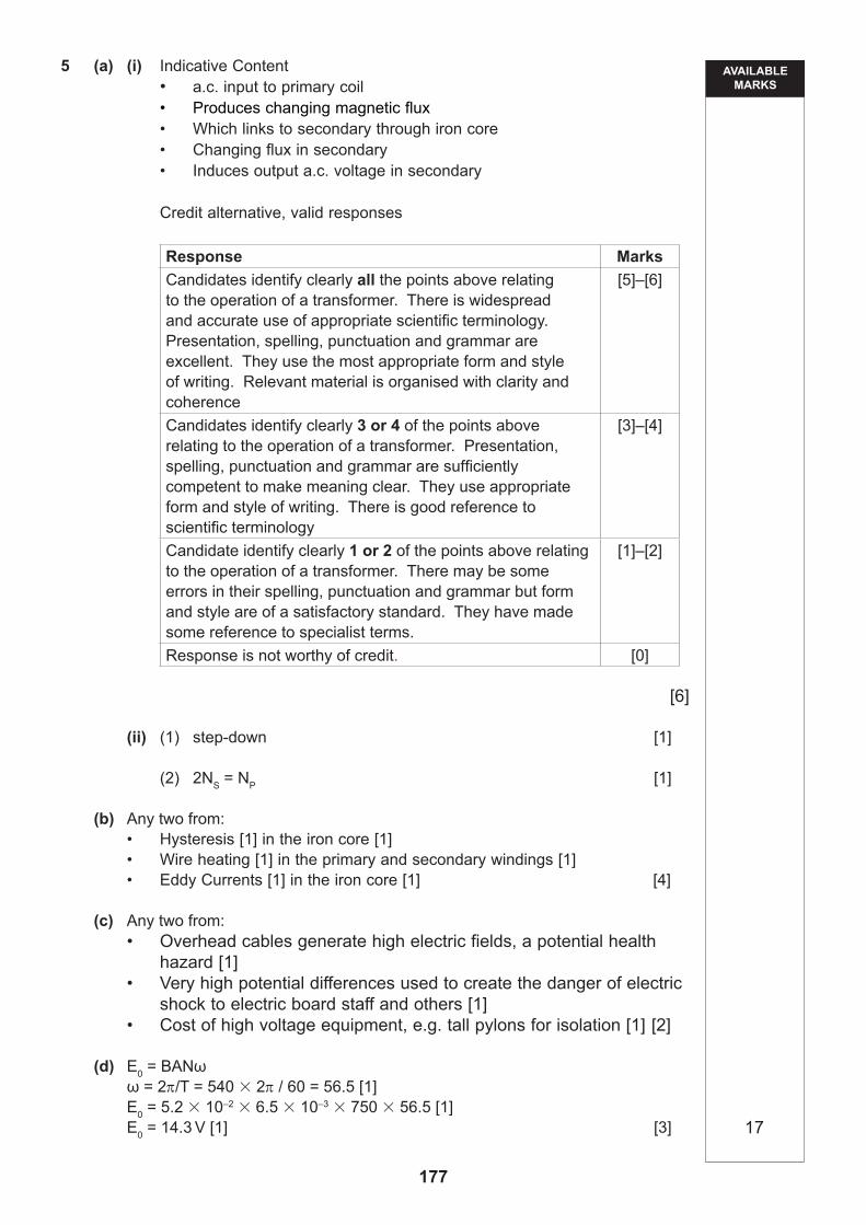
5 (a) (i) Describe how a suitable input voltage, applied to the primary coil of a transformer, results in an output voltage being obtained from the secondary coil.
[6]
(ii) An input voltage is connected to a transformer. An output voltage with half the peak value of the input is required.
(1) State the type of transformer which should be used.
[1]
(2) State the relation which must apply between the number of turns Np in the primary coil and the number of turns Ns in the secondary coil.
[1]
Examiner Only
Marks Re-mark
89 [Turn over
(b) Transformers are not 100% efficient.
State two different sources of energy loss in the form of heat in a transformer.
In each case, state how and where the heat is generated.
[4]
(c) High voltage transmission has advantages in the distribution of electrical power to consumers.
Explain two possible disadvantages in using such a system.
[2]
(d) A simple a.c. generator consists of a coil of wire rotating in a uniform magnetic field of flux density 5.2 10–2 T. The coil has 750 turns, each of area 6.5 10–3 m2. The coil rotates at 540 revolutions per minute.
Calculate the peak e.m.f. of the output of the generator.
e.m.f. V [3]
Examiner Only
Marks Re-mark
90
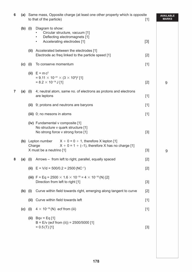
6 (a) Antimatter is matter made up of antiparticles.
What is an antiparticle?
[1]
(b) At the CERN laboratory, antiprotons have been formed using protons accelerated in a synchrotron. The protons are smashed into an iridium rod. The antiprotons produced are separated off using magnets in a vacuum.
(i) Draw and label a diagram to show the structure of a synchrotron.
[3]
(ii) Explain how the synchrotron causes a proton to achieve the kinetic energy needed to form antiprotons during the collision with iridium.
[2]
Examiner Only
Marks Re-mark
91 [Turn over
(c) The annihilation of a positron occurs when it meets an electron. This is represented by the equation
0
01 e –1 e 2 γ
where γ is a photon.
(i) Explain why two photons are produced.
[1]
(ii) Calculate the energy E of each photon produced.
E J [2]
Examiner Only
Marks Re-mark
92
7 (a) Consider a neutral atom of beryllium ( 9 Be).
4
State how many leptons, baryons and mesons a neutral atom of beryllium contains.
Explain your answers.
(i) Number of leptons
Explanation
[1]
(ii) Number of baryons
Explanation
[1]
(iii) Number of mesons
Explanation
[1]
(iv) Baryons and mesons are types of hadrons.
What are the differences between leptons and hadrons?
[3]
Examiner Only
Marks Re-mark
93 [Turn over
(b) Equation 7.1 represents the reaction between a particle X and a neutron. Which results in the formation of a proton and an electron.
X n → p e–
Equation 7.1
In this equation, lepton number is conserved in the same way as charge is conserved. That is, the sum of the lepton numbers on the left-hand side of the equation must equal the sum of the lepton numbers on the right-hand side.
By considering the conservation of charge and the conservation of lepton number, identify particle X.
Reasoning:
Particle X [3]
BLANK PAGE
94
Examiner Only
Marks Re-mark
95 [Turn over
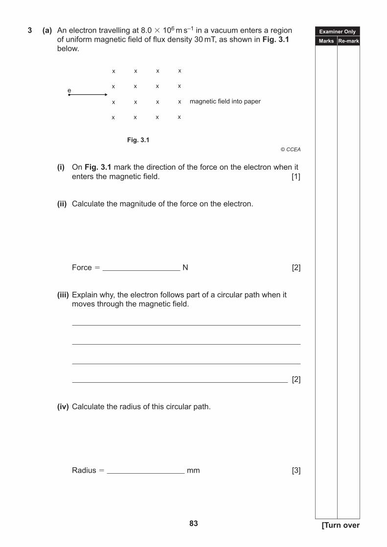
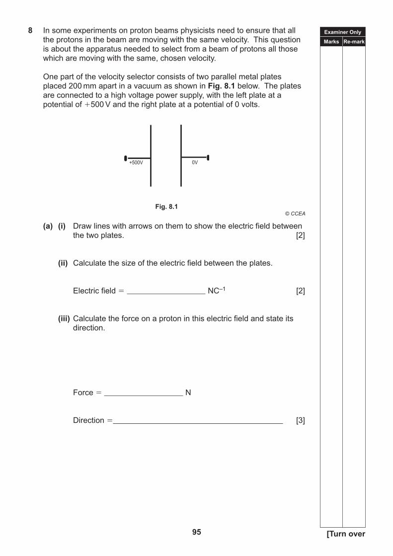
8 In some experiments on proton beams physicists need to ensure that all the protons in the beam are moving with the same velocity. This question is about the apparatus needed to select from a beam of protons all those which are moving with the same, chosen velocity.
One part of the velocity selector consists of two parallel metal plates placed 200 mm apart in a vacuum as shown in Fig. 8.1 below. The plates are connected to a high voltage power supply, with the left plate at a potential of 500 V and the right plate at a potential of 0 volts.
(a) (i) Draw lines with arrows on them to show the electric field between the two plates. [2]
(ii) Calculate the size of the electric field between the plates.
Electric field NC–1 [2]
(iii) Calculate the force on a proton in this electric field and state its direction.
Force N
Direction _____________________________________________________________________________ [3]
+500V 0V
Examiner Only
Marks Re-mark
96
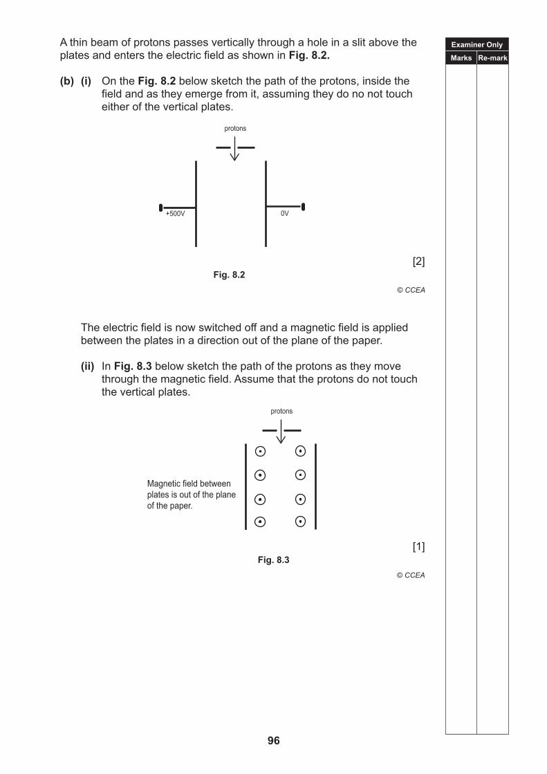
A thin beam of protons passes vertically through a hole in a slit above the plates and enters the electric field as shown in Fig. 8.2.
(b) (i) On the Fig. 8.2 below sketch the path of the protons, inside the field and as they emerge from it, assuming they do no not touch either of the vertical plates.
The electric field is now switched off and a magnetic field is applied between the plates in a direction out of the plane of the paper.
(ii) In Fig. 8.3 below sketch the path of the protons as they move through the magnetic field. Assume that the protons do not touch the vertical plates.
Magnetic field betweenplates is out of the planeof the paper.
+500V 0V
protons
Examiner Only
Marks Re-mark
97 [Turn over
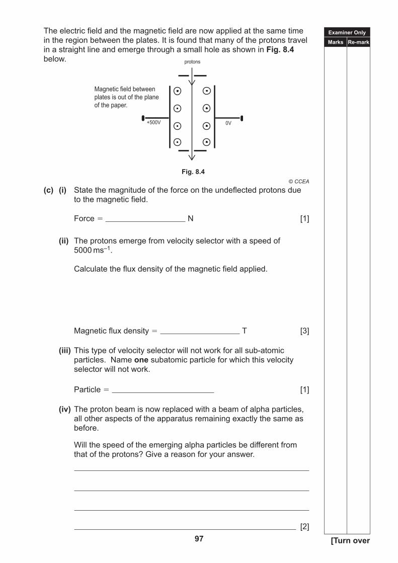
The electric field and the magnetic field are now applied at the same time in the region between the plates. It is found that many of the protons travel in a straight line and emerge through a small hole as shown in Fig. 8.4 below.
(c) (i) State the magnitude of the force on the undeflected protons due to the magnetic field.
Force N [1]
(ii) The protons emerge from velocity selector with a speed of 5000 ms–1.
Calculate the flux density of the magnetic field applied.
Magnetic flux density T [3]
(iii) This type of velocity selector will not work for all sub-atomic particles. Name one subatomic particle for which this velocity selector will not work.
Particle [1]
(iv) The proton beam is now replaced with a beam of alpha particles, all other aspects of the apparatus remaining exactly the same as before.
Will the speed of the emerging alpha particles be different from that of the protons? Give a reason for your answer.
[2]
protons
Magnetic field betweenplates is out of the planeof the paper.
+500V 0V
THIS IS THE END OF THE QUESTION PAPER
98
TIME1 hour.
Write your Centre Number and Candidate Number in the spaces provided at the top of this page.Write your answers in the spaces provided in this question paper.Answer both questions.
The total mark for this paper is 40Figures in brackets printed down the right-hand side of pages indicate the marks awarded to each question or part question.
INSTRUCTIONS TO CANDIDATES
INFORMATION FOR CANDIDATES
For Examiner’suse only
Question Number Marks
1 2
TotalMarks
Physics
Assessment Unit A2 3A
assessing
Practical Techniques and Data Analysis
[CODE]SPECIMEN PAPER
Centre Number
Candidate Number
ADVANCEDGeneral Certificate of Education
2018
99
Examiner Only
Marks Re-mark
100
Answer all questions
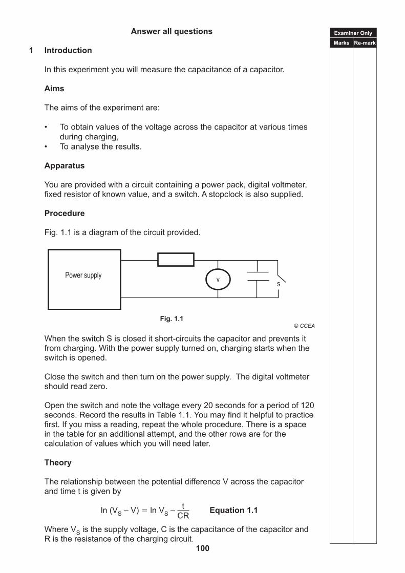
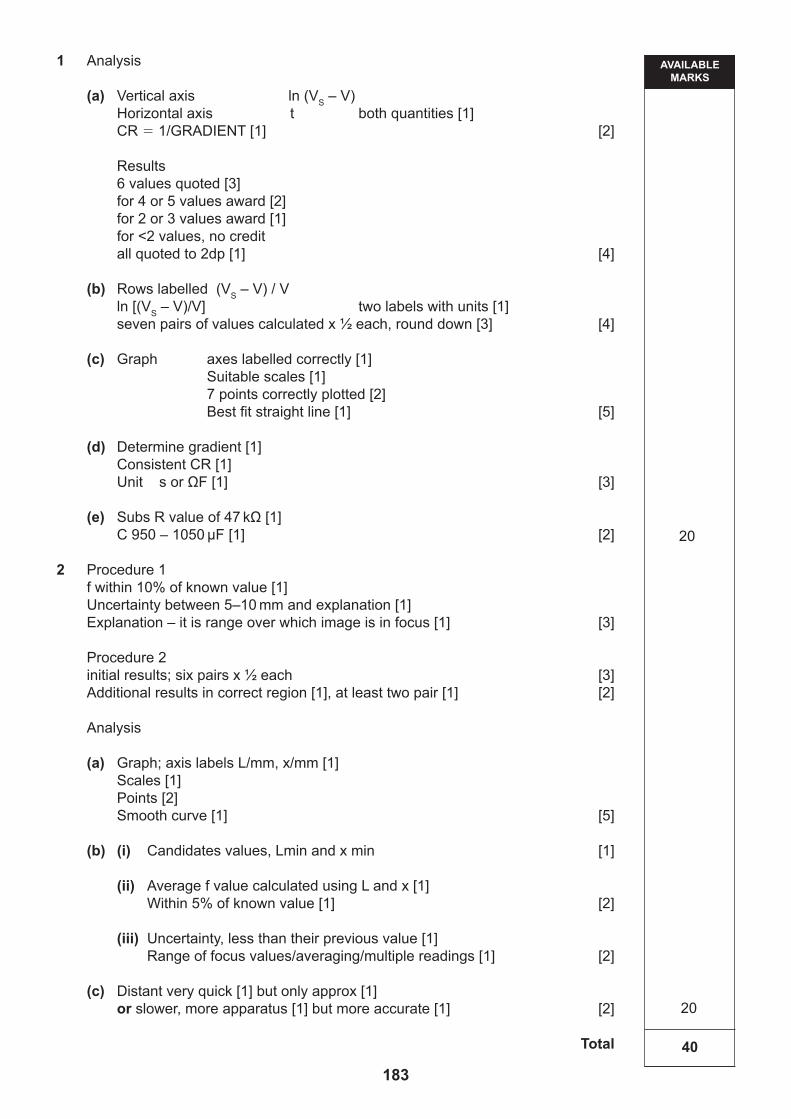
1 Introduction
In this experiment you will measure the capacitance of a capacitor.
Aims
The aims of the experiment are:
• To obtain values of the voltage across the capacitor at various times during charging,
• To analyse the results.
Apparatus
You are provided with a circuit containing a power pack, digital voltmeter, fixed resistor of known value, and a switch. A stopclock is also supplied.
When the switch S is closed it short-circuits the capacitor and prevents it from charging. With the power supply turned on, charging starts when the switch is opened.
Close the switch and then turn on the power supply. The digital voltmeter should read zero.
Open the switch and note the voltage every 20 seconds for a period of 120 seconds. Record the results in Table 1.1. You may find it helpful to practice first. If you miss a reading, repeat the whole procedure. There is a space in the table for an additional attempt, and the other rows are for the calculation of values which you will need later.
Theory
The relationship between the potential difference V across the capacitor and time t is given by
t ln (VS – V) ln VS –
CR Equation 1.1
Where VS is the supply voltage, C is the capacitance of the capacitor and R is the resistance of the charging circuit.
Power supply v s
Examiner Only
Marks Re-mark
101 [Turn over
Analysis
You are to plot a linear graph using Equation 1.1 which will allow you to find CR, and hence calculate C.
(a) State the quantities to be plotted on each axis of the graph.
Vertical (y) axis:
Horizontal (x) axis:
State how CR will be obtained from the graph.
[2]
Results
Table 1.1
t/s 0 20 40 60 80 100 120
V/V 0
[4]
Record also the value of the supply voltage VS, which is provided on a card.
VS ________________ V
(b) To plot the graph in (a), you will need to calculate appropriate quantities from your experimental results. Label each additional row you use in Table 1.1. Include relevant units. Calculate the values needed and enter them in the table. [4]
(c) On the graph grid of Fig. 1.2 on the next page, label the axes and choose suitable scales. Plot the points and draw the best straight line through them. [5]
Examiner Only
Marks Re-mark
102Fig. 1.2
Examiner Only
Marks Re-mark
103 [Turn over
(d) Refer to your answer to (a). From your graph, determine the value of the quantity CR, with its unit.
2 In this experiment you will determine the focal length of a converging lens by two different methods.
Aims
The aims of the experiment are:
• to use optical apparatus to form a focused image at a series of positions;
• to analyse the results to find two values of the focal length from different methods;
• to estimate the uncertainties in the values of the focal length; and • to assess which method is preferable.
Apparatus
You are provided with a metre rule taped to the bench to form a simple optical bench, a lens, a lens holder, a light box with cross-wire aperture, a screen, a half-metre rule and a sheet of plain paper.
Procedure 1: Distant object method for focal length.
Place the sheet of plain paper flat on the bench. Hold the lens above the paper and move it up and down until a focused image of a ceiling light is obtained. The distance from the lens to paper is a value for the focal length f, of the lens. Measure this distance with the half-metre rule and record the value. Also record a value for the uncertainty you judge to exist for the value of the focal length. Give an explanation for your estimate of the uncertainty.
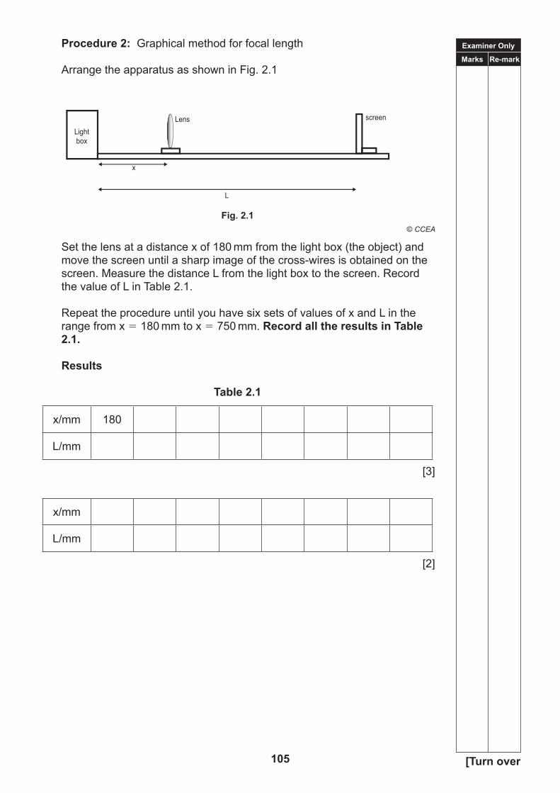
Set the lens at a distance x of 180 mm from the light box (the object) and move the screen until a sharp image of the cross-wires is obtained on the screen. Measure the distance L from the light box to the screen. Record the value of L in Table 2.1.
Repeat the procedure until you have six sets of values of x and L in the range from x 180 mm to x 750 mm. Record all the results in Table 2.1.
Results
Table 2.1
x/mm 180
L/mm
[3]
x/mm
L/mm
[2]
Examiner Only
Marks Re-mark
106
Analysis
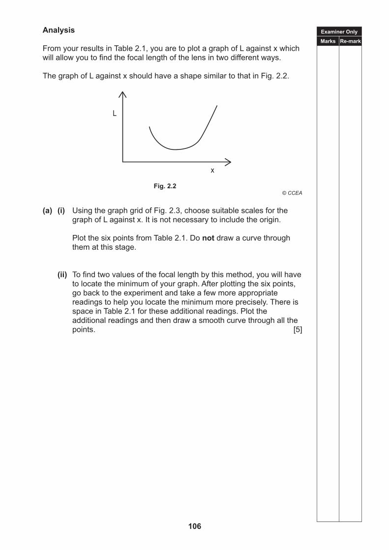
From your results in Table 2.1, you are to plot a graph of L against x which will allow you to find the focal length of the lens in two different ways.
The graph of L against x should have a shape similar to that in Fig. 2.2.
(a) (i) Using the graph grid of Fig. 2.3, choose suitable scales for the graph of L against x. It is not necessary to include the origin.
Plot the six points from Table 2.1. Do not draw a curve through them at this stage.
(ii) To find two values of the focal length by this method, you will have to locate the minimum of your graph. After plotting the six points, go back to the experiment and take a few more appropriate readings to help you locate the minimum more precisely. There is space in Table 2.1 for these additional readings. Plot the additional readings and then draw a smooth curve through all the points. [5]
x
L
107
(b) (i) From your graph in Fig. 2.3, estimate the values of L and x at the minimum of the curve.
Value of L at the minimum ___________________ mm
Value of x at the minimum ___________________ mm [1]
Examiner Only
Marks Re-mark
Fig. 2.3
Examiner Only
Marks Re-mark
108
(ii) The value of L at the minimum is 4f, where f is the focal length of the lens, and the value of x at the minimum is 2f.
Use your values in b(i) to the best value for the focal length f of the lens.
f ___________________ mm [2]
(iii) Estimate the uncertainty in determining the focal length by the graphical method. Explain how you arrive at this uncertainty.
Uncertainty in f ± ___________________ mm
Explanation:
[2]
(c) Which method, the distant object method or the graphical method would you recommend to a fellow student who needs to find the focal length of a lens? Give reasons for your choice.
[2]
THIS IS THE END OF THE QUESTION PAPER
109
BLANK PAGE
110
TIME1 hour.
INSTRUCTIONS TO CANDIDATESWrite your Centre Number and Candidate Number in the spaces provided at the top of this page.Write your answers in the spaces provided in this question paper.Answer all three questions.
INFORMATION FOR CANDIDATESThe total mark for this paper is 50.Figures in brackets printed down the right-hand side of pages indicate the marks awarded to each question or part question.
For Examiner’suse only
Question Number Marks
1 2 3
TotalMarks
Physics
Assessment Unit A2 3Bassessing
Practical Techniques and Data Analysis
[CODE]SPECIMEN PAPER
Centre Number
Candidate Number
ADVANCEDGeneral Certificate of Education
2018
111
Examiner Only
Marks Re-mark
112
Answer all questions
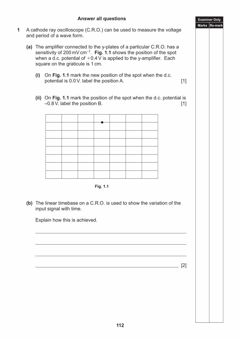
1 A cathode ray oscilloscope (C.R.O.) can be used to measure the voltage and period of a wave form.
(a) The amplifier connected to the y-plates of a particular C.R.O. has a sensitivity of 200 mV cm–1. Fig. 1.1 shows the position of the spot
when a d.c. potential of 0.4 V is applied to the y-amplifier. Each square on the graticule is 1 cm.
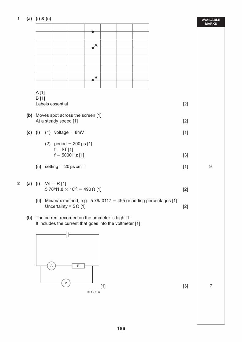
(i) On Fig. 1.1 mark the new position of the spot when the d.c. potential is 0.0 V. label the position A. [1]
(ii) On Fig. 1.1 mark the position of the spot when the d.c. potential is –0.8 V. label the position B. [1]
Fig. 1.1
(b) The linear timebase on a C.R.O. is used to show the variation of the input signal with time.
Explain how this is achieved.
[2]
Examiner Only
Marks Re-mark
113 [Turn over
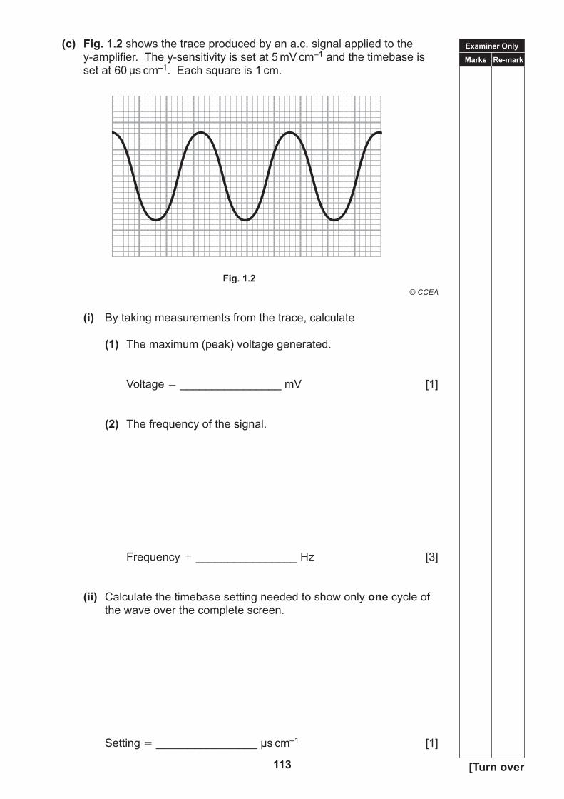
(c) Fig. 1.2 shows the trace produced by an a.c. signal applied to the y-amplifier. The y-sensitivity is set at 5 mV cm–1 and the timebase is set at 60 µs cm–1. Each square is 1 cm.
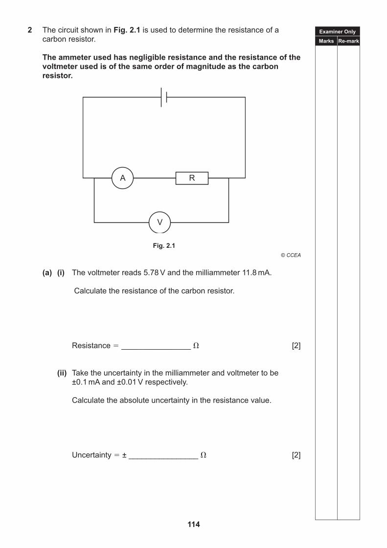
(a) (i) The voltmeter reads 5.78 V and the milliammeter 11.8 mA.
Calculate the resistance of the carbon resistor.
Resistance ________________ [2]
(ii) Take the uncertainty in the milliammeter and voltmeter to be ±0.1 mA and ±0.01 V respectively.
Calculate the absolute uncertainty in the resistance value.
Uncertainty ± ________________ [2]
Examiner Only
Marks Re-mark
115 [Turn over
(b) Theactualresistanceofthecarbonresistoris510Ω.
Explain why the resistance determined from this arrangement should give an inaccurate value.
Draw the circuit you would use to give a more accurate value.
[3]
Examiner Only
Marks Re-mark
116
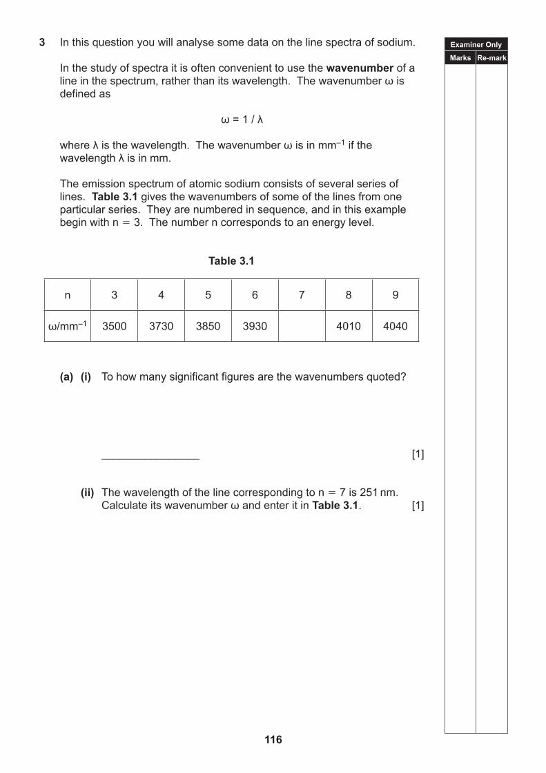
3 In this question you will analyse some data on the line spectra of sodium.
In the study of spectra it is often convenient to use the wavenumber of a lineinthespectrum,ratherthanitswavelength.Thewavenumberωisdefined as
ω=1/λ
whereλisthewavelength.Thewavenumberωisinmm–1 if the wavelengthλisinmm.
The emission spectrum of atomic sodium consists of several series of lines. Table 3.1 gives the wavenumbers of some of the lines from one particular series. They are numbered in sequence, and in this example begin with n 3. The number n corresponds to an energy level.
Table 3.1
n 3 4 5 6 7 8 9
ω/mm–1 3500 3730 3850 3930 4010 4040
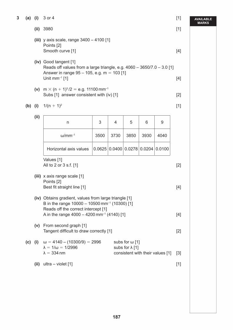
(a) (i) To how many significant figures are the wavenumbers quoted?
________________ [1]
(ii) The wavelength of the line corresponding to n 7 is 251 nm. CalculateitswavenumberωandenteritinTable 3.1. [1]
117
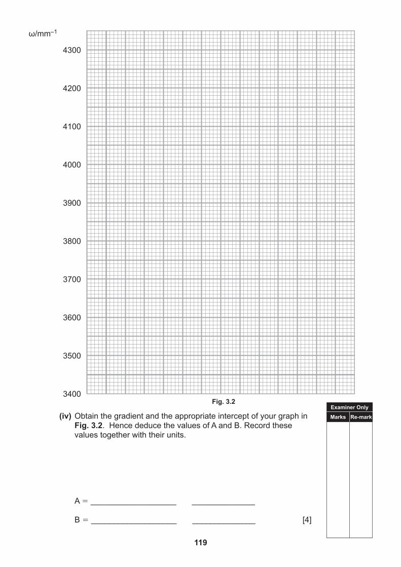
(iii) You are to use the values in Table 3.1toplotagraphofωagainstn on the graph grid of Fig. 3.1.
Considertherangeofvaluesofωandselectasuitablescaleforthe vertical axis. Plot the points and draw the best smooth curve through them. [4]
Fig. 3.1
(iv) Determine the slope, m, of your curve at n 5 and record its
value and unit.
m ________________ unit ________________ [4]
ω/mm–1
n3 4 5 6 7 8 9
Examiner Only
Marks Re-mark
Examiner Only
Marks Re-mark
118
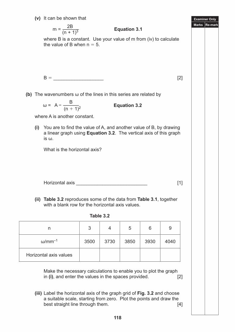
(v) It can be shown that
Equation 3.1
where B is a constant. Use your value of m from (iv) to calculate the value of B when n 5.
(i) You are to find the value of A, and another value of B, by drawing a linear graph using Equation 3.2. The vertical axis of this graph isω.
What is the horizontal axis?
Horizontal axis ___________________________ [1]
(ii) Table 3.2 reproduces some of the data from Table 3.1, together with a blank row for the horizontal axis values.
Table 3.2
n 3 4 5 6 9
ω/mm–1 3500 3730 3850 3930 4040
Horizontal axis values
Make the necessary calculations to enable you to plot the graph
in (i), and enter the values in the spaces provided. [2]
(iii) Label the horizontal axis of the graph grid of Fig. 3.2 and choose a suitable scale, starting from zero. Plot the points and draw the best straight line through them. [4]
2Bm= (n + 1)3
ω=A− B
(n 1)2
119
ω/mm–1
3400
3500
3600
3700
3800
3900
4000
4100
4200
4300
Fig. 3.2
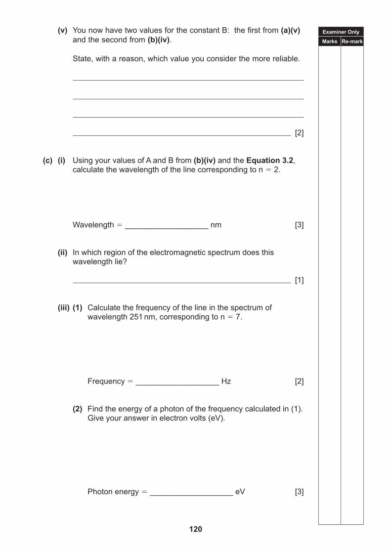
(iv) Obtain the gradient and the appropriate intercept of your graph in Fig. 3.2. Hence deduce the values of A and B. Record these values together with their units.
A ___________________ ______________
B ___________________ ______________ [4]
Examiner Only
Marks Re-mark
Examiner Only
Marks Re-mark
120
(v) You now have two values for the constant B: the first from (a)(v) and the second from (b)(iv).
State, with a reason, which value you consider the more reliable.
[2]
(c) (i) Using your values of A and B from (b)(iv) and the Equation 3.2, calculate the wavelength of the line corresponding to n 2.
Wavelength ___________________ nm [3]
(ii) In which region of the electromagnetic spectrum does this
wavelength lie?
[1]
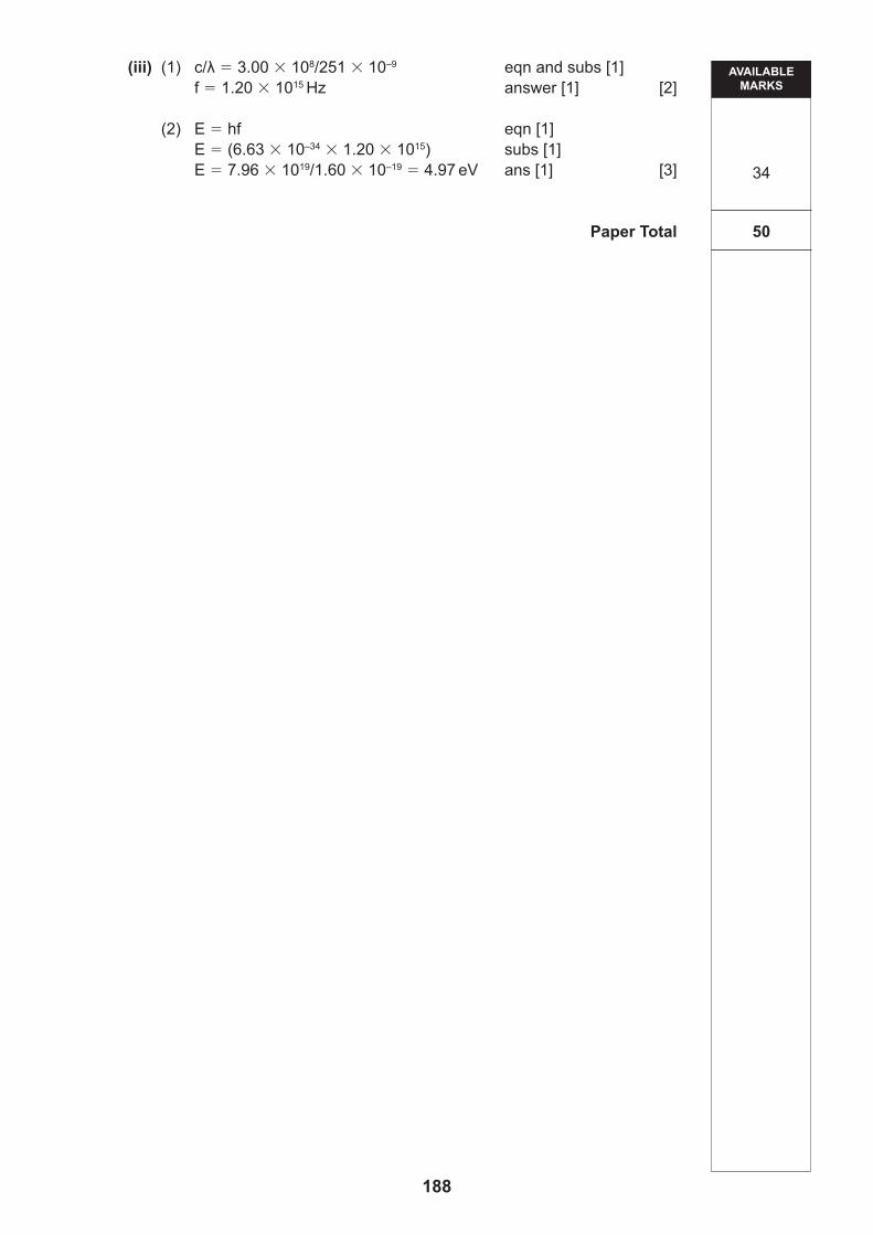
(iii) (1) Calculate the frequency of the line in the spectrum of wavelength 251 nm, corresponding to n 7.
Frequency ___________________ Hz [2]
(2) Find the energy of a photon of the frequency calculated in (1). Give your answer in electron volts (eV).
Photon energy ___________________ eV [3]
THIS IS THE END OF THE QUESTION PAPER
121
BLANK PAGE
122
DATA AND FORMULAE SHEET
Physics
[CODE]SPECIMEN
ADVANCED SUBSIDIARY General Certificate of Education
2018
Assessment Unit AS
123
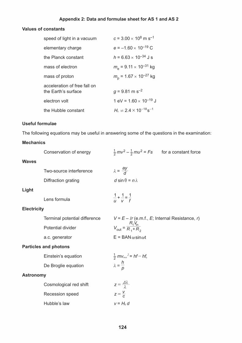
Appendix 2: Data and formulae sheet for AS 1 and AS 2
Values of constants
speed of light in a vacuum c = 3.00 108 m s–1
elementary charge e = –1.60 10–19 C
the Planck constant h = 6.63 10–34 J s
mass of electron me = 9.11 10–31 kg
mass of proton mp = 1.67 10–27 kg
acceleration of free fall on the Earth’s surface g = 9.81 m s–2
electron volt 1 eV = 1.60 10–19 J
the Hubble constant 2.4 10 sH 18 10 #c - -
Useful formulae
The following equations may be useful in answering some of the questions in the examination:
Mechanics
Conservation of energy 1–2 mv 2 – 1–2 mu 2 = Fs for a constant force
Waves
Two-source interference = day
Diffraction grating sind n=i
Light
Lens formula 1 1 1u+v=f
Electricity
Terminal potential difference V = E – Ir (e.m.f., E; Internal Resistance, r)
Potential divider Vout = R VR +R
1 in
1 2
a.c. generator E = BAN~sin t~
Particles and photons
Einstein’s equation 1–2 mv hf hfmax2= - 0
De Broglie equation = hp
Astronomy
Cosmological red shift z V=
Recession speed z cv=
Hubble’s law v H d0=
124
DATA AND FORMULAE SHEET
Physics
[CODE]SPECIMEN
ADVANCED SUBSIDIARY General Certificate of Education
2018
Assessment Unit A2
125
126
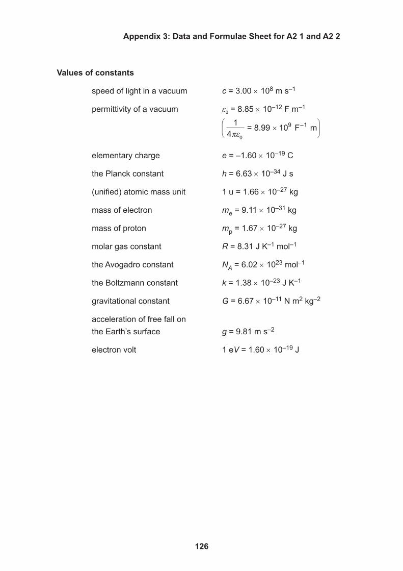
Appendix 3: Data and Formulae Sheet for A2 1 and A2 2
Values of constants
speed of light in a vacuum c = 3.00 108 m s–1
permittivity of a vacuum 0 = 8.85 10–12 F m–1
14
F m–1πε
= 8.99 × 10⁹
0
elementary charge e = –1.60 10–19 C
the Planck constant h = 6.63 10–34 J s
(uni ed) atomic mass unit 1 u = 1.66 10–27 kg
mass of electron me = 9.11 10–31 kg
mass of proton mp = 1.67 10–27 kg
molar gas constant R = 8.31 J K–1 mol–1
the Avogadro constant NA = 6.02 1023 mol–1
the Boltzmann constant k = 1.38 10–23 J K–1
gravitational constant G = 6.67 10–11 N m2 kg–2
acceleration of free fall on the Earth’s surface g = 9.81 m s–2
electron volt 1 eV = 1.60 10–19 J
127
[Turn over
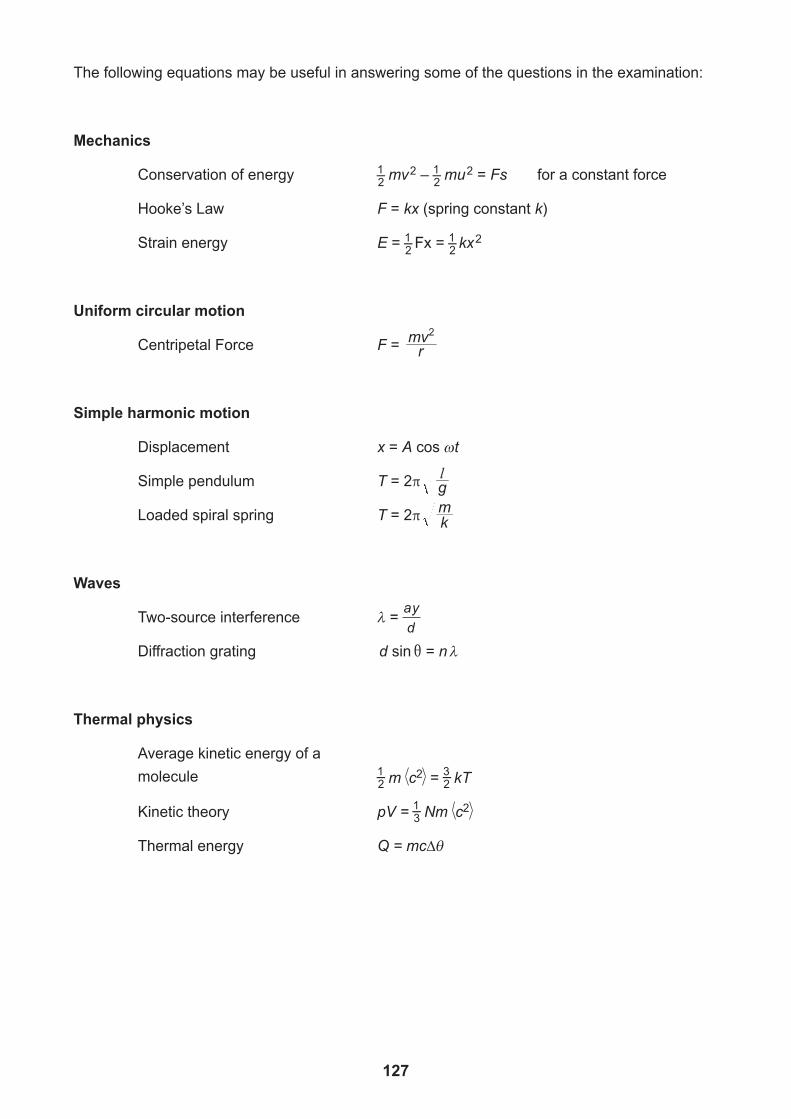
Useful formulae
The following equations may be useful in answering some of the questions in the examination:
Mechanics
Conservation of energy 1–2 mv 2 – 1–2 mu 2 = Fs for a constant force
Hooke’s Law F = kx (spring constant k)
Strain energy E = 1–2 Fx = 1–2 kx 2
Uniform circular motion
Centripetal Force F = rmv2
Simple harmonic motion
Displacement x = A cos t
Simple pendulum T = 2π gl
Loaded spiral spring T = 2π km
Waves
Two-source interference = ayd
Diffraction grating sind n=i
Thermal physics
Average kinetic energy of a molecule 1–2 m c2 = 3–2 kT
Kinetic theory pV = 1–3 Nm c2
Thermal energy Q = mc∆
128
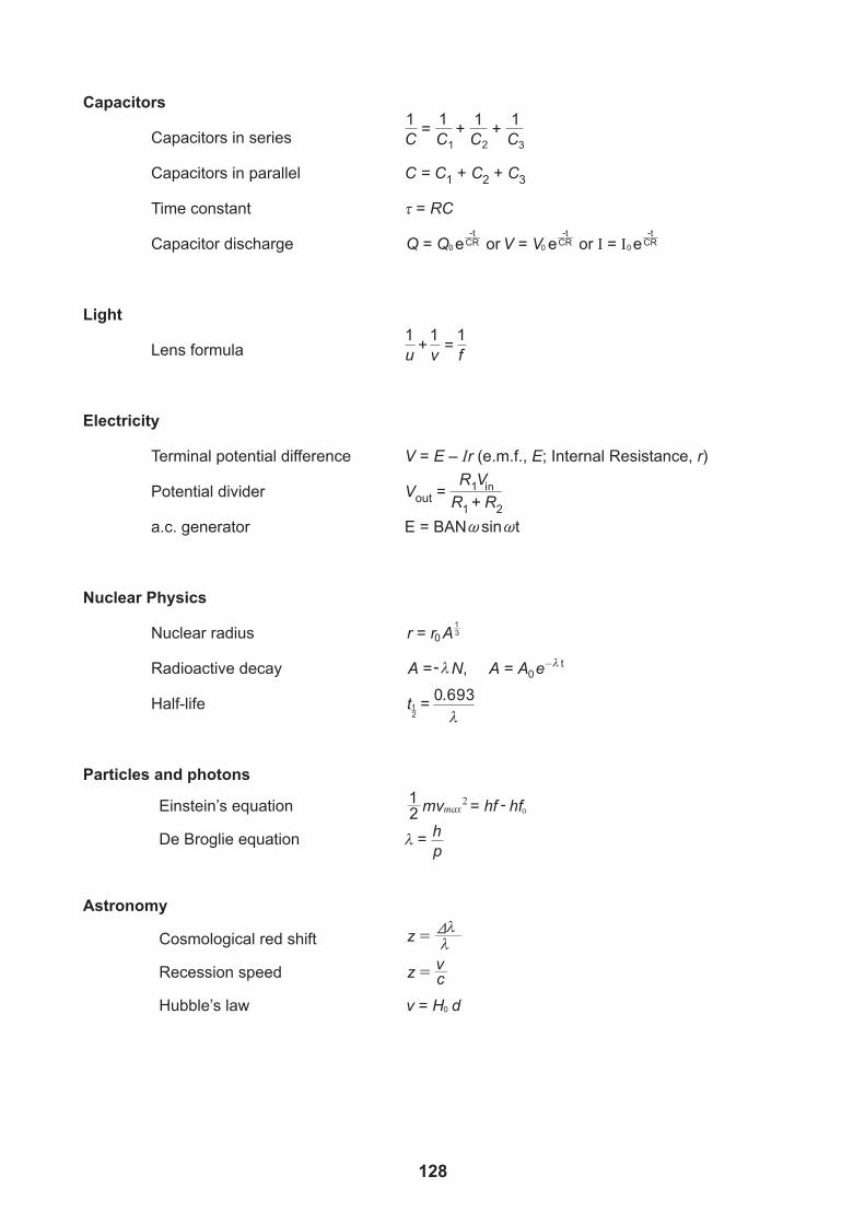
Capacitors
Capacitors in series = + +1 11 1
Capacitors in parallel C = C1 + C2 + C3
Time constant = RC
Capacitor discharge e e eor orQ Q V V I I0 0 0CRt
CRt
CRt
= = =- - -
Light
Lens formula 1
u v f+ =
Electricity
Terminal potential difference V = E – Ir (e.m.f., E; Internal Resistance, r)
Potential divider Vout = R VR R
1 in+
a.c. generator E = BAN
Nuclear Physics
Nuclear radius 0r r 31
= A
Radioactive decay ,A N A A e t=- = -0
Half-life t1–2 =
0 693.λ
Particles and photons
Einstein’s equation 21 mv hf hf2
max = - 0
De Broglie equation = hp
Astronomy
Cosmological red shift
Recession speed z cv=
Hubble’s law v H d0=
~sin t~
z V=
APPARATUS AND MATERIALS LIST
AND
CONFIDENTIAL INSTRUCTIONS
Physics
[CODE]SPECIMEN
ADVANCED General Certificate of Education
2017
Assessment Unit AS 3A
Practical Techniques and Data Analysis
129
130
PHYSICS UNIT 3 (AS 3A)APPARATUS AND MATERIALS REQUIRED FOR PRACTICAL ASSESSMENTS
1 Apparatus and Materials List
In April, prior to carrying out the Practical Techniques Assessment units, centres will receive a copy of the Apparatus and Materials list for both the AS 3A and A2 3A units. As is normally the case, this will include preliminary information on the apparatus and materials required for the practical assessments. Information about the apparatus and the materials required for these assessments must NOT be communicated to students. If apparatus/materials have their serial code and/or manufacturer specified then it is essential that centres use this exact apparatus. On receipt of the Apparatus and Materials list, centres must contact the CCEA Science Subject Officer ([email protected]) immediately if they have difficulty in sourcing the specified apparatus. The Apparatus and Materials List will also contain details of the timing of sessions that can be used for both practical assessments. As always, if more than one available session is being used, care must be taken to segregate candidates who have taken the assessment from those who have still to sit the assessment.
2 Final Apparatus Testing
The practical assessment question paper will be made available to the Head of Department two working days before the timetabled starting time so that teachers and technicians can carry out a final test on the experiments. If on checking, the apparatus gives unexpected results, the CCEA Science Subject Officer should be contacted immediately ([email protected]). If the problem cannot be resolved, then the centre must e-mail the CCEA Science Subject Officer and CCEA Science Support Officer ([email protected]) stating the centre name and number, the specific nature of the problem and the range of anomalous results produced. CCEA will respond by acknowledging receipt of the e-mail. If you do not receive a response within 24 hours, please contact the CCEA Science Subject Officer or Support Officer by telephone (028 90261406) to confirm that CCEA has received your e-mail.
3 Practical Assessment AS3A
The AS 3A Practical Techniques Assessment is a test of practical skills comprised of 4 short experimental tests. The duration of the assessment is 1 hour. Some of this time will be set aside for supervisors to re-set the apparatus ready for the next candidates. The assessment should be run as a circus of experiments with candidates moving to the next experiment at the designated time. The assessment should be timed as follows:
Questions Time Q1 (Short practical test) 13 minutes Changeover and practical write-up 2 minutes Q2 (Short practical test) 13 minutes Changeover and practical write-up 2 minutes Q3 (Short practical test) 13 minutes Changeover and practical write-up 2 minutes Q4 (Short practical test) 13 minutes Changeover and practical write-up 2 minutes
At the end of the 13 minute period, candidates must stop using the apparatus. During each 2 minute changeover period candidates may continue with their write up, however they will not have access to the apparatus.
131
4 After the Practical Assessments
When the individual exam sessions have finished, please return the AS 3A and A2 3A practical scripts together with the corresponding advice notes to the examinations officer (EO). We will collect these by the day after the examination. If we don’t, please contact us immediately to arrange another time for collection.
Where the centre finds that a candidate may have been disadvantaged because the apparatus did not function as intended, the supervising teachers should make a report to the EO. The EO will forward the confidential report on the issue and the candidates affected to the centre support section at CCEA for special consideration. Candidates should be identified by their examination number.
IMPORTANT NOTICE Centres are urged to order items needed for the Physics Practical Tests from the
suppliers as soon as possible.
132
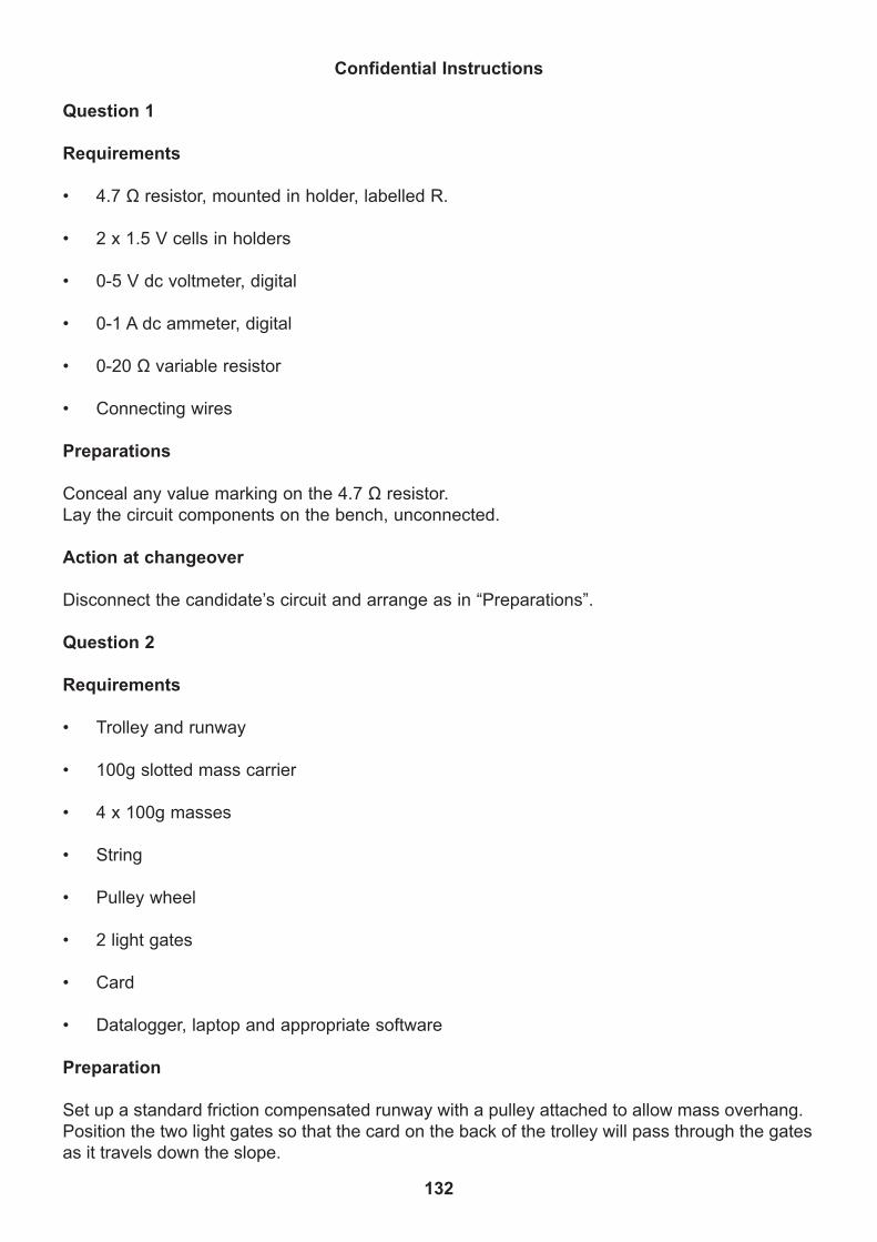
Confidential Instructions
Question 1
Requirements
• 4.7 Ω resistor, mounted in holder, labelled R.
• 2 x 1.5 V cells in holders
• 0-5 V dc voltmeter, digital
• 0-1 A dc ammeter, digital
• 0-20 Ω variable resistor
• Connecting wires
Preparations
Conceal any value marking on the 4.7 Ω resistor.Lay the circuit components on the bench, unconnected.
Action at changeover
Disconnect the candidate’s circuit and arrange as in “Preparations”.
Question 2
Requirements
• Trolley and runway
• 100g slotted mass carrier
• 4 x 100g masses
• String
• Pulley wheel
• 2 light gates
• Card
• Datalogger, laptop and appropriate software
Preparation
Set up a standard friction compensated runway with a pulley attached to allow mass overhang. Position the two light gates so that the card on the back of the trolley will pass through the gates as it travels down the slope.
133
Prepare the software by entering the card width and choosing the option that will automatically calculate and display the acceleration.Place the 4 x 100g slotted masses and the carrier beside the arrangement.
Action at changeover
Remove the slotted masses and carrier.Reset the computer software for a new set of values.
Question 3
Requirements
• Ray box
• A4 white pages (6 per candidate)
• Rectangular glass or Perspex block
• Protractor and ruler
Preparation
Place all the components together on the bench
Action at changeover
Remove all used white pages and replace with 6 clean sheets.Place all the components on the bench as before.
Question 4
Requirements
• Metal column of approximate dimensions, diameter 15mm, height 80mm
• Micrometer screw gauge, 0-25mm, analogue or digital
• Vernier calipers, 0-150mm, analogue or digital
• Half metre rule
• Newton balance 0-10N
• Digital top pan balance
Preparation
Place all the components together on the bench.Check all apparatus properly zeroed.
Action at changeover
Reposition all the apparatus as before.
BLANK PAGE
134
APPARATUS AND MATERIALS LIST
AND
CONFIDENTIAL INSTRUCTIONS
Physics
[CODE]SPECIMEN
ADVANCED General Certificate of Education
2018
Assessment Unit A2 3A
Practical Techniques and Data Analysis
135
136
PHYSICS UNIT 3 (A2 3A)APPARATUS AND MATERIALS REQUIRED FOR PRACTICAL ASSESSMENTS
1 Apparatus and Materials List
In April, prior to carrying out the Practical Techniques Assessment units, centres will receive a copy of the Apparatus and Materials List for both the AS 3A and A2 3A units. This will include preliminary information on the apparatus and materials required for the Practical Assessments. Information about the apparatus and the materials required for these assessments must not be communicated to students. If apparatus/materials have their serial code and/or manufacturer specified then it is essential that centres use this exact apparatus. On receipt of the Apparatus and Materials List, centres must contact the CCEA Science Subject Officer ([email protected]) immediately if they have difficulty in sourcing the specified apparatus. The Apparatus and Materials List will also contain details of the timing of sessions that can be used for both practical assessments. As always, if more than one available session is being used, care must be taken to segregate candidates who have taken the assessment from those who have still to sit the assessment.
2 Final Apparatus Testing
The practical assessment question paper will be made available to the Head of Department two working days before the timetabled starting time so that teachers and technicians can carry out a final test on the experiments. If, on checking, the apparatus gives unexpected results, the CCEA Science Subject Officer should be contacted immediately ([email protected]). If the problem cannot be resolved, then the centre must e-mail the CCEA Science Subject Officer and CCEA Science Support Officer ([email protected]) stating the centre name and number, the specific nature of the problem and the range of anomalous results produced. CCEA will respond by acknowledging receipt of the e-mail. If you do not receive a response within 24 hours, please contact the CCEA Science Subject Officer or Support Officer by telephone (028 90261406) to confirm that CCEA has received your e-mail.
3 Practical Assessment A2 3A
The A2 3A Practical Techniques Assessment is a test of practical skills comprised of two experimental tests (40 marks). The duration of the assessment is 1 hour. Some of this time will be set aside for supervisors to re-set apparatus for the next candidates. In each of the experimental tests (Q1 and Q2), candidates must stop using the apparatus after 28 minutes. At the end of each 28 minute period, a changeover time of 2 minutes will be set aside for the supervisor to re-set the apparatus for the next candidates. During the changeover periods, candidates may continue with their write-up, however they will not have access to the apparatus. Candidates will move on to the next question after 30 minutes. The supervisor can decide in which order the candidates should attempt the questions.
4 After the Practical Assessment
When the individual exam sessions have finished, please return the AS 3A and A2 3A practical scripts together with the corresponding advice notes to the examinations officer (EO). We will collect these by the day after the examination. If we don’t, please contact us immediately to arrange another time for collection.
137
Where the centre finds a candidate may have been disadvantaged because the apparatus did not function as intended, the supervising teachers should make a report to the EO. The EO will forward the confidential report on the issue and the candidates affected to the centre support section at CCEA for special consideration. Candidates should be identified by their examination number.
IMPORTANT NOTICE Centres are urged to order items needed for the Physics Practical Tests from the
suppliers as soon as possible.
138
Confidential Instructions
Question 1
Requirements
• Power supply, about 10 V dc smoothed
• Voltmeter, 0-20 V, digital
• Capacitor, 470 µF
• Resistor, 100 kΩ
• Stopclock
• Component holders
• Switch
Preparation
• Use a label to conceal any markings on the 100 kΩ resistor. Write RESISTOR R on the label.
• Attach the resistor to one of the component holders.• Use a label to conceal any markings on the 470F capacitor. Write CAPACITOR C on the
label.• Clearly mark the plus and minus ends of the capacitor for use when connecting the circuit.• Attach the capacitor to the other component holder.• Set the power pack to approximately 10 V and use the voltmeter to measure the exact
output.• Write this value on a card as, for example Vˢ = 10.3 V.• • Leave this card on the bench beside the power supply.• On the power supply, tape over the controls and unneeded sockets.• Connect the circuit shown in fig1.1 on the paper.
Testing
Switch on the power supply and close the switch. The voltmeter should read zero. Open the switch. The capacitor should start to charge and should reach nearly 10 V after about 120s
Action at changeover
Switch off the power supply and close the switch. Check that the voltmeter reads 0 V.
• Measure, to the nearest 5mm, the focal length of each of the lens to be used in the examination. If possible, select lenses with focal lengths in the range 95mm to 105mm.Candidates will be required to use the lens to obtain a focused image of a nearby ceiling light.
• Select a position for the experiment below such a light. Place the sheet of paper on the bench below the light and check that a reasonably bright, focused image can be obtained, even in sunlight.
• Place a reference mark on the lens holder below the optical centre of the lens when it is in the holder. Attach the metre rule to the bench with adhesive tape. Position the light box at the end of the rule in such a way that the lens and screen can be placed against the metre rule, forming a simple optical bench.
• Check that it is possible to slide the lens holder and/or screen along the edge of the rule to form an image of crosswires on the screen. If necessary, adjust the height of either screen of lens holder so that the image on the screen is always formed at the same height above the bench as that of the crosswires.
• The optical bench arrangement is to be left assembled for candidates’ use.• Check that both light box and ceiling lights are on.
Testing
Check that, with the lens 120mm from the crosswires, a sharp image can be formed when the screen is approximately 600mm from the lens.
Action at changeover
Confirm that the image of the crosswires can be obtained on the screen.
BLANK PAGE
140
MARK SCHEME
141
DIVIDER FRONT
142
MARK SCHEME
DIVIDER BACK
General Certificate of Education
GENERAL MARKING INSTRUCTIONS
Physics
143
General Marking Instructions
IntroductionThe main purpose of the mark scheme is to ensure that examinations are marked accurately, consistently and fairly. The mark scheme provides examiners with an indication of the nature and range of candidates’ responses likely to be worthy of credit. It also sets out the criteria which they should apply in allocating marks to candidates’ responses.
Assessment objectivesBelow are the assessment objectives for GCE Physics:
Candidates should be able to:
AO1 Demonstrate knowledge and understanding of Physics ideas, processes, techniques and procedures.
AO2 Apply knowledge and understanding of Physics ideas, processes, techniques and procedures:• in a range of theoretical and practical contexts;• when handling qualitative and quantitative data; and• to solve scientific problems.
AO3 Analyse, interpret and evaluate a range of Physics information, ideas and evidence to:• make judgements and reach conclusions (including in relation to issues);• refine practical design and procedures;• make, record and communicate reliable and valid observations and
measurements with appropriate precision and accuracy.
Quality of candidates’ responsesIn marking the examination papers, examiners should be looking for a quality of response reflecting the level of maturity which may reasonably be expected of a 17 or 18-year-old which is the age at which the majority of candidates sit their GCE examinations.
Flexibility in markingMark schemes are not intended to be totally prescriptive. No mark scheme can cover all the responses which candidates may produce. In the event of unanticipated answers, examiners are expected to use their professional judgement to assess the validity of answers. If an answer is particularly problematic, then examiners should seek the guidance of the Supervising Examiner.
Positive markingExaminers are encouraged to be positive in their marking, giving appropriate credit for what candidates know, understand and can do rather than penalising candidates for errors or omissions. The exception to this for GCE Physics is when Examiners are marking complex calculations and mechanisms when the Examiners are briefed to mark by error or omission. Examiners should make use of the whole of the available mark range for any particular question and be prepared to award full marks for a response which is as good as might reasonably be expected of a 17 or 18-year-old GCE candidate.
Awarding zero marksMarks should only be awarded for valid responses and no marks should be awarded for an answer which is completely incorrect or inappropriate.
144
Marking CalculationsIn marking answers involving calculations, examiners should apply the error carried forward (ecf) rule so that candidates are not penalised more than once for a computational error. To avoid a candidate being penalised, marks can be awarded where correct conclusions or inferences are made from their incorrect calculations.
Types of mark schemesIn A2, mark schemes for tasks or questions which require candidates to respond in extended written form are marked on the basis of levels of response which take account of the quality of written communication.
Other questions which require only short answers are marked on a point for point basis with marks awarded for each valid piece of information provided.
Levels of responseIn deciding which level of response to award, examiners should look for the number of indicative content points in candidate responses to ensure that the answer has been written to coincide with the question. In deciding which mark within a particular level to award to any response, quality of communication will be assessed and examiners are expected to use their professional judgement.
The following guidance is provided to assist examiners.
• Threshold performance: Response which just merits inclusion in the level but the quality of communication is basic should be awarded a mark at the bottom of the range.
• High performance: Response which fully satisfies the level description for both content and quality of communication should be awarded a mark at the top of the range.
Quality of written communicationQuality of written communication is taken into account in assessing candidates’ responses to all tasks and questions on theory examination papers that require them to respond in extended written form. These tasks and questions are marked on the basis of levels of response. The description for each level of response includes reference to the quality of written communication.
For conciseness, quality of written communication is distinguished within levels of response as follows:
Level 1 Quality of written communication is basic.Level 2 Quality of written communication is good.Level 3 Quality of written communication is excellent.
In interpreting these level descriptions, examiners should refer to the more detailed guidance provided below:
Level 1 (Basic): Basic reference to scientific terminology. The candidate makes only a limited selection and use of an appropriate form and style of writing. The organisation of material may lack clarity and coherence. There is little use of specialist vocabulary. Presentation, spelling, punctuation and grammar may be such that intended meaning is not clear.
145
Level 2 (Good): Good reference to scientific terminology. The candidate makes a reasonable selection and use of an appropriate form and style of writing. Relevant material is organised with some clarity and coherence. There is some use of appropriate specialist vocabulary. Presentation, spelling, punctuation and grammar are sufficiently competent to make meaning clear.
Level 3 (Excellent): Excellent reference to scientific terminology. The candidate successfully selects and uses the most appropriate form and style of writing. Relevant material is organised with a high degree of clarity and coherence. There is widespread and accurate use of appropriate specialist vocabulary. Presentation, spelling, punctuation and grammar are of a sufficiently high standard to make meaning clear.
146
MARKSCHEME
ADVANCED SUBSIDIARYGeneral Certificate of Education
2017
Physics
Assessment Unit AS 1assessing
Forces, Energy and Electricity
[CODE]SPECIMEN
147
148
Subject-specific Instructions
In numerical problems, the marks for the intermediate steps shown in the mark scheme are for the benefit of candidates who do not obtain the final correct answer. A correct answer and unit, if obtained from a valid starting-point, gets full credit, even if all the intermediate steps are not shown. It is not necessary to quote correct units for intermediate numerical quantities.
Note that this “correct answer” rule does not apply for formal proofs and derivations, which must be valid in all stages to obtain full credit.
Do not reward wrong physics. No credit is given for consistent substitution of numerical data, or subsequent arithmetic, in a physically incorrect equation. However, answers to subsequent stages of questions that are consistent with an earlier incorrect numerical answer, and are based on physically correct equation, must gain full credit. Designate this by writing ECF (Error Carried Forward) by your text marks.
The normal penalty for an arithmetical and/or unit error is to lose the mark(s) for the answer/unit line. Substitution errors lose both the substitution and answer marks, but 10n errors (e.g. writing 550 nm as 550 10–6 m) count only as arithmetical slips and lose the answer mark.
149
AVAILABLE MARKS
1 (a) scalar has magnitude only, vector has magnitude and direction [1]
(b) kelvin or mole [1] Temperature or quantity of substance [1] [2]
(c) Quantity Scalar Vector Unit
Velocity ü m s–1
Kinetic energy ü kg m2 s–2
Charge ü A s
Resistance ü kg m2 s–3 A–2
4 x 1 [5]
2 (a) any direction in the first quadrant, [1] Not including vertical and horizontal [1] [2]
(b) horizontal 170 cos 30 147 N [1] Vertical 170 sin 30 85 N [1] [2]
(c) 147 N or ecf from (b) [1]
(d) Fvert + 170 sin 30 250 [1] Fvert 250 – 85 165 N [1] [2]
(e) F2 1472 + 1652 [1] or ecf from (c) and (d) F 221 N [1] Tan θ 165 / 147 [1] F is at an angle of 48.3° above the horizontal [1] [4]
8
11
1
150
AVAILABLE MARKS
3 (i) (v-u) / a t [1] 27–21 / 2 t 3 s [1] [2]
(ii) One horizontal line from 21 [1] Diagonal line 21–27 for 3 secs, [1] then horizontal [1] [3]
(iii) 48 2 96 m to make up [1] For the first 3 s a 9 m catch up [1] 6 m catch up every second thereafter, [1] 87 / 6 14.5 [1] Time 3 + 14.5 17.5 s [1] [5]
(iv) 17.5 27 472.5 [1] 472.5 – 9 463.5 m [1] [2]
(v) Car being overtaken does not change speed [1]
4 (a) vertical component 25 sin 35° ( 14.3) [1] Time to reach max. height 14.3 / 9.81 1.46 [1] [2]
(b) s ut - ½gt2 or v2 u2 – 2gs [1] Max height 10.5 m or ecf [1] [2]
(c) Time of flight 2 time to reach max. height [1] Horizontal component 25 cos 35° ( 20.5 m s–1) [1] S vhorz t [1] S 59.8 m or ecf [1] [4]
(d) At time t 0.6 s Vertical component of velocity 8.45 m s–1 [1] Horizontal component 20.5 m s–1
V2 vvert2 vhorz
2
V 22.16 m s–1 [1] tan θ = 8.45/20.48 [1] θ = 22.42° to horizontal [1] [4]
5 (a) (i) Impulse mv – mu [1] 0.15 (25 – [–40]) subs [1] double negative [1] 9.75 kg m s–1 or N s answer [1] unit [1] [5]
(ii) Impulse F t [1] F 9.75 / 0.01 975 N [1] [2]
(b) m1u1 m2u2 m1v1 + m2v2 [1] 1.5 1.0 1.2 0 1.5 v 1.2 0.8 lhs [1] rhs [1] [2] V 0.36 m s–1 [1] [4]
13
12
11
151
AVAILABLE MARKS
6 (i) A correctly proportioned diagram including all components described [1] All forces and distances correctly labelled [1] [2]
(ii) Moments about R1 1.5 80 9.8 1.0 30 9.8 2 R2 [1] R2 735 N [1] equilibrium of forces WM WP R1 R2 [1] 30 9.8 80 9.8 R1 R2 [1] R1 343 N [1] [5]
(iii) Moments about R1 80 D 1.0 30 [1] D 0.375 [1] Distance from the end 0.5 – 0.375 0.125 m [1] [3]
7 (i) v – u at [1] a (2 – 0)/ 5 0.4 m s–2 [1] [2]
(ii) R – W ma up positive [1] R mg + ma [1] R 60 10.2 [1] R 613 N [1] [4]
(iii) (1) a 0 therefore R W [1] (2) a negative value R < W [1] [2]
(iv) Apply T – W ma [1] T m (9.8 – 0.8) [1] T 660 9 5940 N [1] [3]
8 (a) (i) For a conductor under constant physical conditions or constant temperature [1] Current is proportional to potential difference [1] [2]
(ii) (1) e.g. copper or metal [1] (2) Linear graph through the origin [1] [2]
(iii) Device is a non-ohmic conductor [1] because current not proportional to potential difference [1] [2]
(b) R Current through* (wire) and corresponding voltage across* (wire)
measured [1] *one stated or both Stating R = V/I [1]
A Micrometer to measure diameter [1] At least twice and average [1] Equation to calculate A: A πd2/4 or r d/2 and A πr2 [1] [5]
V labels [1] R labels [1] [3] (c) (i) R resistance of parallel combination of 5.0 k Ω and 0.20 k Ω 1 / R 1/5.0 1/ 0.20 [1] R 0.192 k Ω [1] Vout 12 0.192 /(5 0.192) [1] Vout 0.44 V ans to at least 2 sig fig to confirm valid [1] [4]
(ii) if R 0, Vdark Vill or equivalent [1]
Paper Total
13
100
MARKSCHEME
ADVANCED SUBSIDIARYGeneral Certificate of Education
2017
PhysicsAssessment Unit AS 2
assessing
Waves, Photons and Astronomy
[CODE]SPECIMEN
153
154
Subject-specific Instructions
In numerical problems, the marks for the intermediate steps shown in the mark scheme are for the benefit of candidates who do not obtain the final correct answer. A correct answer and unit, if obtained from a valid starting-point, gets full credit, even if all the intermediate steps are not shown. It is not necessary to quote correct units for intermediate numerical quantities.
Note that this “correct answer” rule does not apply for formal proofs and derivations, which must be valid in all stages to obtain full credit.
Do not reward wrong physics. No credit is given for consistent substitution of numerical data, or subsequent arithmetic, in a physically incorrect equation. However, answers to subsequent stages of questions that are consistent with an earlier incorrect numerical answer, and are based on physically correct equation, must gain full credit. Designate this by writing ECF (Error Carried Forward) by your text marks.
The normal penalty for an arithmetical and/or unit error is to lose the mark(s) for the answer/unit line. Substitution errors lose both the substitution and answer marks, but 10n errors (e.g. writing 550 nm as 550 10–6 m) count only as arithmetical slips and lose the answer mark.
155
AVAILABLE MARKS1 (a) (i) Wave in which oscillations are in one plane only [1]
(ii) f = 11.3 109 [1] λ = c/f = 3.00 108 / 11.3 109 [1] wavelength = 2.65 10–2 m [1] [3]
(iii) Microwave [1]
(b) (i) Oscillations of the particles parallel to the direction of propagation of the wave [1]
(ii) Sound [1]
(c) (i) amplitude = 4 cm [1]
(ii) Period = 2 ms [1] Frequency = 500 Hz [1] [2]
(iii) Phase difference = 90° or π/2 rad [1]
2 (a) (i) Labelled diagram to show illuminated object and screen with converging lens between them, metre rule (optical bench) and u and v distances identified.
Items [1] Labels [1] [2]
(ii) Place lens at a distance from illuminated object > focal length [1] Move screen until clear image on screen [1] Record u, v (as shown in diagram or defined) [1] Repeat 4 more times for different values of u [1] [4]
(iii) Calculate values of (1/u + 1/v) [1] Average [1] Find reciprocal [1]
OR
Draw 1/u vs. 1/v graph Find average of intercepts Find reciprocal [3]
11
156
AVAILABLE MARKS
(b) m = v/u = 50 [1] m = v/u = 100 [1] v = 50 u v = 100 u 1/u + 1/50 u = 1/250 1/u + 1/100 u = 1/250 50/50 u + 1/50 u = 1/250 100/100 u + 1/100 u = 1/250 u = 255 [1] u = 252.5 [1] moved 2.5 mm [1] towards the object [1] [6]
3 (a) (i) Correct wave pattern [1] Two nodes [1] Two antinodes [1] [3]
(ii) length = 3λ / 4 [1] λ = 689 mm [1] use of v = fλ [1] v = 336 m s–1 [1] [4]
(b) (i) signal generator [1]
(ii) Appreciates length = λ / 4 for 282 Hz [1] Three calculations [1] Average [1] V = 345 m s–1 [1] [4]
4 (a) (i) Diffraction spreading at single slit to ensure both of the double slits illuminated [1] Diffraction spreading at each of the double slits to ensure beams overlap [1] Interference in the region of overlap [1] [3]
(ii) Wavelength, λ, increase [1] Slit to screen distance d increase [1] Slit separation a decrease [1] [3]
(ii) θmax= 90°, sinθmax = 1 [1] n = d sinθmax/ λ = 2 10–6 1 / 589 10–9 = 3.4, [1] therefore third order [1] [3]
5 (a) The distant galaxy is moving away from the Milky Way or The distance between the distant galaxy and the Milky Way is increasing as the universe is expanding. [1]
14
12
15
157
AVAILABLE MARKS
(b) (i) z = Δλ / λ = 3 /656 = 4.57 10–3 subs (1) ans (1) [2]
(ii) speed = zc = 4.57 10–3 3 105 = 1370 (km s–1) subs (1) ans (1) [2]
(iii) d = v / Ho = 1.37 103 /2.4 10–18 = 5.71 1020 (km) subs (1) ans (1) [2]
(c) T = 1/Ho = 1 / 2.4 10–18 = 4.167 1017 s = 1.32 1010 years eqt (1) subs (1) ans (1) [3]
6 (a) (i) 1 / focal length [1]
(ii) m–1 or dioptre [1]
(b) (i) short sight or myopia [1]
(ii) eye lens too strong or eyeball too long [1]
(iii) diverging or negative power [1]
(iv) u= ∞ [1] v= – 80 cm or –0.80 m [1] Power = – 1.25 [1] [3]
(c) v = –18 cm f = –80 cm [1] 1/u = 1/–80 + 1/18 [1] Near point distance = 23 cm [1] [3]
7 (a) (1) By collision with other atoms/electron bombardment [1] (2) From incident photons, of the correct energy [1] [2]
(b) (i) ΔE = hf and f = c / λ [1] ΔE = hc / λ [1] = 6.63 10–34 3.00 108 / 1.60 10–19 10–9 λ [1] = 1243, check value [3]
(ii) E to B [1] 1.88 and 10.21 [1] [1] 121 [1] Visible/red and ultra violet [1] [1] [6]
8 (a) (i) Photon absorbed by the metal [1] Releases electrons [1] Deficient in electrons therefore overall positive [1] [3]
(ii) Less uv at ground level [1]
(b) (i) Minimum energy required [1] to release electron from caesium [1] [2]
AVAILABLE MARKS (iii) Photon energy = 2.65 10–19 J = 1.66eV [1]
Less than work function, hence no emission [1] [2]
9 (a) The wavelength associated with matter when behaving as a wave [1]
(b) (i) λ = h/mv
v = h/m λ = 6.63 10–34 /9.1 10–31 1.2 10–10 [1] v = 6.07 106 m s–1 [1] [2]
(ii) eV = ½ mv2 [1]
V = ½ mv2/e = 0.5 9.1 10–31 (6.07 106)2 [1]
1.6 10−19
V = 104.8 V [1] [3]
Paper Total
10
6
100
ADVANCED SUBSIDIARYGeneral Certificate of Education
2017
MARKSCHEME
PhysicsAssessment Unit AS 3A
assessing
Practical Techniques and Data Analysis
[CODE]SPECIMEN
159
160
AVAILABLE MARKS
Mark scheme for Practical Test 1: Determine the resistance of a carbon film resistor.
(a) Workable circuit to obtain valid results [1] Correct circuit symbols used [1] [2]
(b) P.D. measured [1] Corresponding current measured [1] Repetition of measurements [1] until consistency achieved [1] Table headings in form P.D./V and I/A [1] P.D.andcurrentvaluesreflectaccuracyofthemeter[1] [6]
(c) Resistance calculated to R ± 5% (± 10%) [2] [2]
Mark scheme for Practical Test 2: Verification of a α F.
(a) Workable experiment to obtain valid results [1] Workable suggestion to keep mass constant [1] [2]
(b) Accelerating force recorded [1] Corresponding acceleration recorded [1] Repetition (>1) of measurements for each force [1] until consistency achieved [1] Results for >4 forces recorded [1] Table headings in form Force/N and a/m s–2[1] [6]
(b) Incident angle recorded [1] Corresponding refracted angle recorded [1] Results for >4 (>1) incident angles recorded [2] Table headings in form i/° and r/° [1] Incidentanglesinas(des)cendingorder[1] [6]
(c) n value 1.5 ± 5% (±10%) [2] [2]
10
10
10
161
AVAILABLE MARKS
Mark scheme for Practical Test 4: Density
(a) Micrometer screw for diameter [1] Calipers for length [1] Balance for mass [0] [2]
(b) Multiple reading for diameter to 0.01 mm and average [2] Multiple reading for length to 0.1 mm and average [2] Multiplereadingformassto0.01gandaverage[2] [6]
(c) Use of the equation V πr2handρ m/V [1] Value within agreed tolerance and unit [1] [2]
Total
10
40
BLANK PAGE
162
ADVANCED SUBSIDIARYGeneral Certificate of Education
2017
MARKSCHEME
PhysicsAssessment Unit AS 3B
assessing
Practical Techniques and Data Analysis
[CODE]SPECIMEN
163
164
AVAILABLE MARKS
1 (a) Longest length 0.124 m [1] Shortest length 0.115 m [1] [2]
(b) Ignore two rogue values [1] Add each time and divide by the number of valid repeats [1] Quote answers to two decimal places [1] If 4 or more correct values award [2] If 2 or 3 correct values award [1] Otherwise award [0] [5]
(b) (i) The wavelength quoted is outside the visible range. [1]
(ii) Increase the slit to screen distance and use the tape measure [1] Measure the distance between several fringes, not just one [1] Carry the experiment out in a darkened room to improve contrast [1] [3]
Total
11
9
5
50
BLANK PAGE
166
MARK SCHEME
Physics
Assessment Unit A2 1assessing
Momentum, Thermal Physics, Circular Motion, Oscillations and Atomic and Nuclear Physics
[CODE]SPECIMEN
ADVANCEDGeneral Certificate of Education
2018
167
MARKSCHEME
168
AVAILABLE MARKS1 (a) (i) ω=v/r=2.5/2.0[1]
=1.25[1] [2]
(ii) F=mv2/r=30(2.5)2/2.0[1] =94[1] [2]
(iii) v2=Fr/m=1802.0/30[1] =3.5[1] [2]
(b) (i) Tc=W,mv2/r=mg[1] v2=gr v=3.3[1] [2]
(ii) T=mg+mv2/r[1] T=58.8[1] [2]
2 (a) (i) E=FL/AΔL [1]
(ii) Linearsectionfollowedbycorrectcurve[1] Elasticmarkedaslinearsectionandsmallpartofcurve,plastic astherest[1] [2]
Candidateidentifyclearly3 or 4 ofthemainissuesabovethatwouldneedtobeaddressedifthenuclearsolutionisadopted.Oneoftheirissuesmaybewhynuclearenergymaybeanattractivealternativetoconventionalfossilfuelmethods.Presentation,spelling,punctuationandgrammararesufficientlycompetenttomakemeaningclear.Theyuseanappropriateformandstyleofwriting.Thereisgoodreferencetoscientificterminology.
[3]–[4]
Candidatesidentifyclearly1 or 2ofthemainissuesabovethatwouldneedtobeaddressedifthenuclearoptionisadopted.Oneoftheirissuesmaybewhynuclearenergymaybeanattractivealternativetoconventionalfossilfuelmethods.Theremaybesomeerrorsintheirspelling,punctuationandgrammar,butformandstyleareofasatisfactorystandard.Theyhavemadelimitedreferencetospecialistterms.
[1]–[2]
Responseisnotworthyofcredit. [0]
[6]
Paper Total
20
100
BLANK PAGE
172
MARKSCHEME
ADVANCEDGeneral Certificate of Education
2018
Physics
Assessment Unit A2 2assessing
Fields, Capacitors and Particle Physics
[CODE]SPECIMEN
173
174
Subject-specific Instructions
In numerical problems, the marks for the intermediate steps shown in the mark scheme are for the benefit of candidates who do not obtain the final correct answer. A correct answer and unit, if obtained from a valid starting-point, gets full credit, even if all the intermediate steps are not shown. It is not necessary to quote correct units for intermediate numerical quantities.
Note that this “correct answer” rule does not apply for formal proofs and derivations, which must be valid in all stages to obtain full credit.
Do not reward wrong physics. No credit is given for consistent substitution of numerical data, or subsequent arithmetic, in a physically incorrect equation. However, answers to subsequent stages of questions that are consistent with an earlier incorrect numerical answer, and are based on physically correct equation, must gain full credit. Designate this by writing ECF (Error Carried Forward) by your text marks.
The normal penalty for an arithmetical and/or unit error is to lose the mark(s) for the answer/unit line. Substitution errors lose both the substitution and answer marks, but 10n errors (e.g. writing 550 nm as 550 10–6 m) count only as arithmetical slips and lose the answer mark.
(1) Top graph vertical axis flux linkage, unit weber [1] Top value 3 10–2 Wb [1] Bottom value 1.5 10–2 Wb [1] Shape [2] [5]
(2) Bottom graph axis e.m.f., unit volts [1] Top value 90V [1] Bottom value 30V [1] Shape [2] [5]
12
13
0 1 2 3 4 5
177
AVAILABLE MARKS
5 (a) (i) Indicative Content• a.c. input to primary coil• Produces changing magnetic flux• Which links to secondary through iron core• Changing flux in secondary• Induces output a.c. voltage in secondary
Credit alternative, valid responses
Response MarksCandidates identify clearly all the points above relating to the operation of a transformer. There is widespread and accurate use of appropriate scientific terminology. Presentation, spelling, punctuation and grammar are excellent. They use the most appropriate form and style of writing. Relevant material is organised with clarity and coherence
[5]–[6]
Candidates identify clearly 3 or 4 of the points above relating to the operation of a transformer. Presentation, spelling, punctuation and grammar are sufficiently competent to make meaning clear. They use appropriate form and style of writing. There is good reference to scientific terminology
[3]–[4]
Candidate identify clearly 1 or 2 of the points above relating to the operation of a transformer. There may be some errors in their spelling, punctuation and grammar but form and style are of a satisfactory standard. They have made some reference to specialist terms.
[1]–[2]
Response is not worthy of credit. [0]
[6]
(ii) (1) step-down [1]
(2) 2NS = NP [1]
(b) Any two from:• Hysteresis [1] in the iron core [1]• Wire heating [1] in the primary and secondary windings [1]• Eddy Currents [1] in the iron core [1] [4]
(c) Any two from:• Overhead cables generate high electric fields, a potential health
hazard [1]• Very high potential differences used to create the danger of electric
shock to electric board staff and others [1]• Cost of high voltage equipment, e.g. tall pylons for isolation [1] [2]
(iii) y axis scale, range 3400 – 4100 [1] Points [2] Smooth curve [1] [4]
(iv) Good tangent [1] Reads off values from a large triangle, e.g. 4060 – 3650/7.0 – 3.0 [1] Answer in range 95 – 105, e.g. m 103 [1] Unit mm–1 [1] [4]
(iii) x axis range scale [1] Points [2] Best fit straight line [1] [4]
(iv) Obtains gradient, values from large triangle [1] B in the range 10000 – 10500 mm–1 (10300) [1] Reads off the correct intercept [1] A in the range 4000 – 4200 mm–1 (4140) [1] [4]
(v) From second graph [1] Tangent difficult to draw correctly [1] [2]
(c) (i) ω 4140 – (10300/9) 2996 subs for ω [1] λ 1/ω 1/2996 subs for λ [1] λ 334 nm consistent with their values [1] [3]
(ii) ultra – violet [1] [1]
188
AVAILABLE MARKS
(iii) (1) c/λ 3.00 108/251 10–9 eqn and subs [1] f 1.20 1015 Hz answer [1] [2]
(2) E hf eqn [1] E (6.63 10–34 1.20 1015) subs [1] E 7.96 1019/1.60 10–19 4.97 eV ans [1] [3]