ibm.com/redbooks Front cover IBM Communication Controller for Linux on System z V1.2.1 Implementation Guide Bill White Daniela Di Casoli Octavio Ferreira Walter Porschen Mike Riches Concepts and terminology Planning, implementation, and migration guidance Realistic examples and scenarios
Transcript
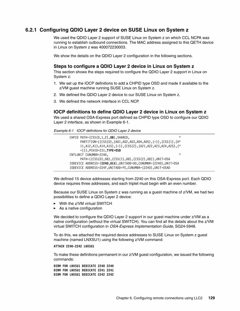
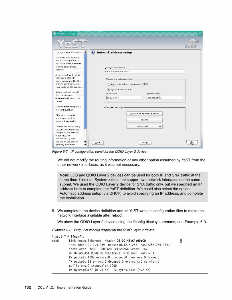
ibm.com/redbooks
Front cover
IBM Communication Controller for Linux on System z V1.2.1Implementation Guide
Bill WhiteDaniela Di CasoliOctavio FerreiraWalter Porschen
This information was developed for products and services offered in the U.S.A.
IBM may not offer the products, services, or features discussed in this document in other countries. Consult your local IBM representative for information on the products and services currently available in your area. Any reference to an IBM product, program, or service is not intended to state or imply that only that IBM product, program, or service may be used. Any functionally equivalent product, program, or service that does not infringe any IBM intellectual property right may be used instead. However, it is the user's responsibility to evaluate and verify the operation of any non-IBM product, program, or service.
IBM may have patents or pending patent applications covering subject matter described in this document. The furnishing of this document does not give you any license to these patents. You can send license inquiries, in writing, to: IBM Director of Licensing, IBM Corporation, North Castle Drive Armonk, NY 10504-1785 U.S.A.
The following paragraph does not apply to the United Kingdom or any other country where such provisions are inconsistent with local law: INTERNATIONAL BUSINESS MACHINES CORPORATION PROVIDES THIS PUBLICATION "AS IS" WITHOUT WARRANTY OF ANY KIND, EITHER EXPRESS OR IMPLIED, INCLUDING, BUT NOT LIMITED TO, THE IMPLIED WARRANTIES OF NON-INFRINGEMENT, MERCHANTABILITY OR FITNESS FOR A PARTICULAR PURPOSE. Some states do not allow disclaimer of express or implied warranties in certain transactions, therefore, this statement may not apply to you.
This information could include technical inaccuracies or typographical errors. Changes are periodically made to the information herein; these changes will be incorporated in new editions of the publication. IBM may make improvements and/or changes in the product(s) and/or the program(s) described in this publication at any time without notice.
Any references in this information to non-IBM Web sites are provided for convenience only and do not in any manner serve as an endorsement of those Web sites. The materials at those Web sites are not part of the materials for this IBM product and use of those Web sites is at your own risk.
IBM may use or distribute any of the information you supply in any way it believes appropriate without incurring any obligation to you.
Information concerning non-IBM products was obtained from the suppliers of those products, their published announcements or other publicly available sources. IBM has not tested those products and cannot confirm the accuracy of performance, compatibility or any other claims related to non-IBM products. Questions on the capabilities of non-IBM products should be addressed to the suppliers of those products.
This information contains examples of data and reports used in daily business operations. To illustrate them as completely as possible, the examples include the names of individuals, companies, brands, and products. All of these names are fictitious and any similarity to the names and addresses used by an actual business enterprise is entirely coincidental.
COPYRIGHT LICENSE: This information contains sample application programs in source language, which illustrates programming techniques on various operating platforms. You may copy, modify, and distribute these sample programs in any form without payment to IBM, for the purposes of developing, using, marketing or distributing application programs conforming to the application programming interface for the operating platform for which the sample programs are written. These examples have not been thoroughly tested under all conditions. IBM, therefore, cannot guarantee or imply reliability, serviceability, or function of these programs. You may copy, modify, and distribute these sample programs in any form without payment to IBM for the purposes of developing, using, marketing, or distributing application programs conforming to IBM's application programming interfaces.
The following terms are trademarks of other companies:
IPX, Java, JRE, and all Java-based trademarks are trademarks of Sun Microsystems, Inc. in the United States, other countries, or both.
Linux is a trademark of Linus Torvalds in the United States, other countries, or both.
Other company, product, or service names may be trademarks or service marks of others.
x CCL V1.2.1 Implementation Guide
Preface
This IBM® Redbook will help you to install, tailor, and configure the IBM Communication Controller for Linux® on System z™ (CCL) V1.2.1. It focuses on the migration of IBM 3745/46 hardware functions and the IBM Network Control Program (NCP) to a CCL environment with easy-to-understand, step-by-step guidance.
The publication provides information to assist you with the planning, implementation, and setup of OSA-Express, Linux, and CCL, and describes helpful utilities and commands that you can use to monitor and operate the CCL environment.
Using realistic scenarios, it explains the changes that are necessary to NCP and VTAM® definitions to support CCL.
The target audience for this redbook includes system engineers, network administrators, and systems programmers who will plan for and install CCL V1.2.1. Readers should have a solid background in SNA networking (VTAM and NCP) and Linux operating systems, as well as OSA-Express setup and OSA/SF usage.
The team that wrote this redbookThis redbook was produced by a team of specialists from around the world working at the International Technical Support Organization, Poughkeepsie Center.
Bill White is a Project Leader and Senior Networking Specialist at the International Technical Support Organization, Poughkeepsie Center.
Daniela Di Casoli is a Certified IT Specialist in Connectivity. She has 16 years of experience in Enterprise Networking. Her areas of expertise include SNA, APPN, and TCP/IP networking. She works in Global Technology Services in IBM Italy.
Octavio Ferreira is a Senior I/T Specialist in IBM Brazil. He has 27 years of experience in IBM software support. His areas of expertise include z/OS® Communications Server, SNA and TCP/IP, Communications Server on all platforms. For the last eight years, he has worked at the Area Program Support Group providing guidance and support to customers, and designing networking solutions such as SNA and TCP/IP integration, z/OS Connectivity, Enterprise Extender design and implementation, and SNA-to-APPN migration.
Walter Porschen is a Senior I/T Specialist in IBM Germany. He has 36 years of experience in IBM support. His areas of expertise include z/OS Communications Server, SNA and TCP/IP. Previous positions include CE education (hardware and software instruction) and customer service for hardware and software (country specialist). For the last 17 years, he has worked on networking support teams at both the country and European level.
Mike Riches is a Network Specialist within Global Technology Services, United Kingdom, providing remote technical support and on-site consultancy for IBM clients in Europe and South Africa. He has 14 years of experience as a Network Systems Programmer, both with IBM and a number of major IBM clients. He has achieved Senior accreditation in the Product Services Profession since joining IBM in 2002. His areas of expertise include z/OS Communications Server, traditional subarea SNA, APPN, and TCP/IP networking.
As with any complex technical effort, success would not have been possible without the advice, support, and review of many outstanding technical professionals from within IBM. We are especially thankful for the significant contributions and guidance from the follow people:
Brian Baker, Chris Chato, Alfred Christensen, Chuck Gardiner, Arnie Hackett, Mike Law, Erika Lewis, Joe Mason, Tom McSweeney, Bob Perrone, and Suvas Shah
Thanks also to the International Technical Support Organization, Poughkeepsie center, for their invaluable support in this project, particularly:
Dave Bennin, Roy Costa, Rich Conway, Greg Geiselhart, and Bob Haimowitz
Become a published authorJoin us for a two- to six-week residency program! Help write an IBM Redbook dealing with specific products or solutions, while getting hands-on experience with leading-edge technologies. You'll team with IBM technical professionals, Business Partners and/or customers.
Your efforts will help increase product acceptance and customer satisfaction. As a bonus, you'll develop a network of contacts in IBM development labs, and increase your productivity and marketability.
Find out more about the residency program, browse the residency index, and apply online at:
ibm.com/redbooks/residencies.html
Comments welcomeYour comments are important to us!
We want our Redbooks™ to be as helpful as possible. Send us your comments about this or other Redbooks in one of the following ways:
� Use the online Contact us review redbook form found at:
In today’s IT environment, companies are simplifying their networks and moving toward an on demand environment. They want to move off older, slower-networking hardware in order to be able to take advantage of newer technology. At the same time, they want to preserve their investment in current applications and continue to use solutions that they have come to rely on.
The IBM Communication Controller for Linux on System z is software that emulates IBM 3745/46 hardware and runs in the mainframe. Communication Controller for Linux (CCL) provides an attractive migration solution, integrating the latest networking hardware with existing mission-critical software.
In this chapter we introduce the capabilities of CCL and discuss the following:
1.1 Why CCL is importantThe IBM 3745/46 Communication Controller hardware family was withdrawn from marketing in 2002. The IBM Communication Controller for Linux on System z9™ and zSeries® (CCL) was developed as a migration path from this hardware. CCL enables the Network Control Program (NCP) software that runs on IBM 3745/46 hardware to run in Linux on System z9 or zSeries hardware. The result is elimination of the dependencies on older IBM 3745/46 hardware.
The mainframe Linux platform is a strategic environment for running many key software solutions along with CCL. In the past, NCPs were connected to the host via Token Ring or ESCON® channel attachments. Many Token Ring products are also being withdrawn from marketing and ESCON channel chips are no longer manufactured. Therefore, moving the NCP to CCL removes a non-strategic hardware dependency through the use of Ethernet technology.
So not only does CCL reduce your dependency on aging hardware—but running an NCP in Linux on mainframe servers also provides many other advantages. For example, you can leverage the strengths of System z9 and zSeries hardware, known for reliability, security, scalability and business resiliency. In addition, CCL with Linux can run in either native LPAR mode or as a z/VM® guest. You can also use lower-cost Integrated Facility for Linux (IFL) processor for handling the CCL workload.
Communication Controller for Linux on System z is an attractive migration alternative that integrates the advantages of System z9 and zSeries hardware, virtual servers, and the Linux operating system with the reliability of your existing NCP software and SNA applications.
1.1.1 Who should consider CCLThere are a number of SNA installations that still rely on the IBM 3745/46 environment and can make use of CCL’s capabilities; for example, SNA installations which have:
� Moved most SNA traffic off the IBM 3745/46 environment, but have SNI business partners who are unable to move away from SNI
� Moved some IBM 3745/46 functions, but still require NCP support for the existing infrastructure (such as IBM 327x serial line-attached terminal equipment)
� Planned to set up disaster recovery sites, but can no longer purchase IBM 3745/46s
� Struggled with data center raised floor space and power consumption issues regarding the IBM 3745/46
In addition, Communication Controller for Linux supports an SNA migration evolving towards simplified networks inclusive of IP network infrastructure and enhanced hardware independence, while continuing to operate and leverage the value in existing SNA application portfolios. Moving NCP functions to the System z9 or zSeries server can allow the SNA network to continue to be consolidated into the server, more closely integrating SNA applications and the NCP. This evolutionary migration can allow not only network simplification, but also the continuing use of critical SNA applications.
1.1.2 Why on the mainframe platformIBM decided to provide 3745/46 emulation on the mainframe because the mainframe offers a number of advantages over other platforms.
2 CCL V1.2.1 Implementation Guide
These advantages include:
� Higher levels of reliability� A wider range of scalability options� Proven business resiliency for mission-critical applications
Another benefit is that you do not have to implement an additional server platform into the mainframe data center, thus simplifying the environment and reducing overall operational costs.
Likewise, the OSA-Express features on the mainframe provide offload capabilities that allow for high-performance connectivity, as well as the appropriate support for SNA connectivity.
Implementing CCL so that it runs in a logical partition or as a z/VM guest ensures that it can work seamlessly with all the current mainframe operating systems (z/OS, Z/VM, z/VSE™, and z/TPF).
Using Linux for System z makes for a cost-effective and convenient server consolidation effort. Rather than requiring additional hardware and raised floor space, CCL is a shared resource within the mainframe.
System z9 and zSeries servers offer an attractive option for customers who want to use the IBM Integrated Facility for Linux (IFL)1 processor and z/VM, which can support a range of many images per processor. A controller can be created or started based on the demands of your network; if you need another controller, you just start another instance that may be in the same Linux image. You may also run in different Linux images for high availability. In addition to help reduce the dependency on IBM 3745/46 hardware, lower-speed network connectivity such as Token Ring or ESCON hardware can be replaced with high-speed OSA-Express adapters in the System z9 or zSeries servers.
The mainframe is a good choice because of the ability to optimize the processing of CCL; part of the emulator is written in System z assembler, which exploits various advanced features in the OSA-Express environment that do not exist on other platforms. For example, Layer 2 support and the capability to share OSA-Express ports across multiple logical partitions, which are also very important from a virtualization perspective.
CCL also allows you to have integration points as close to the SNA applications as possible, minimizing the reach of any SNA network that is in place.
1.1.3 Simplified migration The support of existing, unmodified NCP software helps simplify migration to Communication Controller for Linux on System z (CCL) from the IBM 3745/46 Communication Controller. Definition updates are usually simple and are only required by the NCP moving into Linux on System z; in most cases there are no coordinated changes required by business partners.
From an operational point of view, CCL provides interfaces that allow you to load, operate, manage, and dump NCPs. CCL has its own MOSS console, which is used to manage and operate NCPs running on Linux such as starting and stopping the Communication Controller, dumping NCP or the Communication Controller, and displaying and altering storage. These are provided by CCL via an easily accessible browser interface.
1 Linux workload on the IFL processor does not result in any increased IBM software charges for the traditional System z9 and zSeries operating systems and middleware. IFLs are not supported on S/390® G5/G6 servers.
Chapter 1. Introduction 3
By offering an alternative platform for running NCP software, CCL enables a possible migration path for the following IBM Communication Controller products:
� IBM 3705 Communication Controller � IBM 3720 Communication Controller � IBM 3725 Communication Controller � IBM 3745 Communication Controller � IBM 3746-900 Nways® Multiprotocol Controller
1.2 Basic conceptsCCL is a virtualized communication controller that runs on an IBM System z9 or zSeries server and consists of a Linux user-space and kernel-space. In the user-space, a CCL Engine accommodates the MOSS console and NCP load module, while the CCL Data Link Switching support (CCL DLSw) is a separate program.
The Network Device Handler (NDH) and the Linux device drivers run in the kernal-space. Figure 1-1 shows the CCL components.
Figure 1-1 CCL components
The CCL Engine emulates an IBM 3745-31A with 16 MB memory supporting an NCP load module2 and a MOSS console interface. The MOSS console is accessed through a standard Web browser.
NDH is a kernel extension that acts as the interface between a real network interface (such as an OSA port) and the NCP Token Ring Interface (NTRI). The only supported local area
2 NCPs from any 3745/46 model are supported.
CCL MOSS
ConsoleNCP Load
Module
CCL Engine
Linux on System z
User
Kernel
CCL
OSA Express
Linux device driver
Network Device Handler (NDH)
CCL DLSw
4 CCL V1.2.1 Implementation Guide
network (LAN) interfaces, from an NCP perspective, are the TIC2 and TIC3 interfaces. The actual LAN to which the OSA port is connected can be Token Ring or Ethernet. NDH will convert the frame formats when an Ethernet interface is used. NDH consists of two components:
1. A small source code isolation module that is built during installation of CCL
2. An object code only NDH module
Both are dynamically loaded into kernel-space. No kernel rebuild/reboot is required.
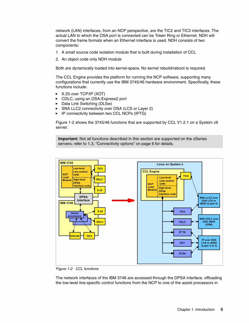
The CCL Engine provides the platform for running the NCP software, supporting many configurations that currently use the IBM 3745/46 hardware environment. Specifically, these functions include:
� X.25 over TCP/IP (XOT) � CDLC, using an OSA-Express2 port� Data Link Switching (DLSw)� SNA LLC2 connectivity over OSA (LCS or Layer 2)� IP connectivity between two CCL NCPs (IPTG)
Figure 1-2 shows the 3745/46 functions that are supported by CCL V1.2.1 on a System z9 server.
Figure 1-2 CCL functions
The network interfaces of the IBM 3746 are accessed through the DPSA interface, offloading the low-level line-specific control functions from the NCP to one of the assist processors in
Important: Not all functions described in this section are supported on the zSeries servers; refer to 1.3, “Connectivity options” on page 6 for details.
Assist processors
TIC2
SDLC
X.25
X.25
SDLC
TIC3ESCON
IBM 3745
IBM 3746
DPSA Interface
NCP Load Module
Low-levelLine control code
High-levelDPSA interface code
NCP Load Module
Low-levelLine control code
High-levelDPSA interface code
TIC3
CDLC
IP TG
XOT
TIC2
SNA LLC2 over OSA LCS or
QDIO (Layer 2)
SNA CDLC over OSA QDIO
(OSN)
IP over OSA LCS or QDIO (Layer 2 or 3)
Linux on System z
CCL Engine
DLSw
Chapter 1. Introduction 5
the IBM 3746 frame. This capability is also provided for an NCP running in CCL, which means:
� Improved performance, because fewer instructions are processed by the CCL Engine � Improved multi-processing capabilities - handing work from the CCL Engine process to
other processes in Linux
The TIC2 interface is also supported with CCL V1.2.1. However, the TIC3 interface provides higher throughput. Therefore, the use of TIC3 interface definitions is the preferred method for SNA LLC2 connections when setting up the CCL V1.2.1 environment.
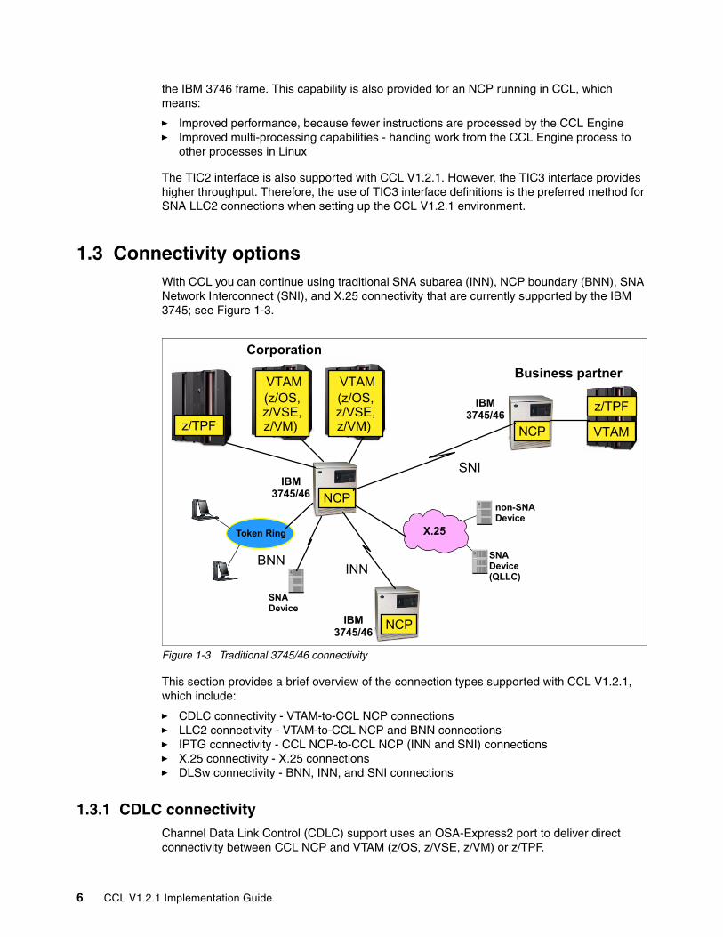
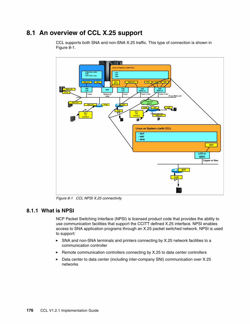
1.3 Connectivity optionsWith CCL you can continue using traditional SNA subarea (INN), NCP boundary (BNN), SNA Network Interconnect (SNI), and X.25 connectivity that are currently supported by the IBM 3745; see Figure 1-3.
Figure 1-3 Traditional 3745/46 connectivity
This section provides a brief overview of the connection types supported with CCL V1.2.1, which include:
1.3.1 CDLC connectivityChannel Data Link Control (CDLC) support uses an OSA-Express2 port to deliver direct connectivity between CCL NCP and VTAM (z/OS, z/VSE, z/VM) or z/TPF.
Token Ring
SNI
Corporation
IBM 3745/46 NCP
VTAM(z/OS, z/VSE, z/VM)
Business partner
NCP VTAM z/TPF
VTAM(z/OS, z/VSE, z/VM)
X.25
SNA Device (QLLC)
non-SNA Device
INN
NCP
IBM 3745/46
IBM 3745/46
SNA Device
z/TPF
BNN
6 CCL V1.2.1 Implementation Guide
The OSA Express2 1000BASE-T and Gigabit Ethernet features on System z9 support a CHPID type known as OSA for NCP (OSN).
TPF and VTAM see the OSA Express OSN port as a channel-attached IBM 3745 to which they communicate using the usual CDLC channel protocol. Because of this, existing configuration definitions remain unchanged and activation and management flows continue to work as before (for example, the Load/Dump functions over a channel are fully supported).
TPF or VTAM must reside in the same System z9 server as the CCL NCP; see Example 1-4.
Figure 1-4 CDLC connectivity
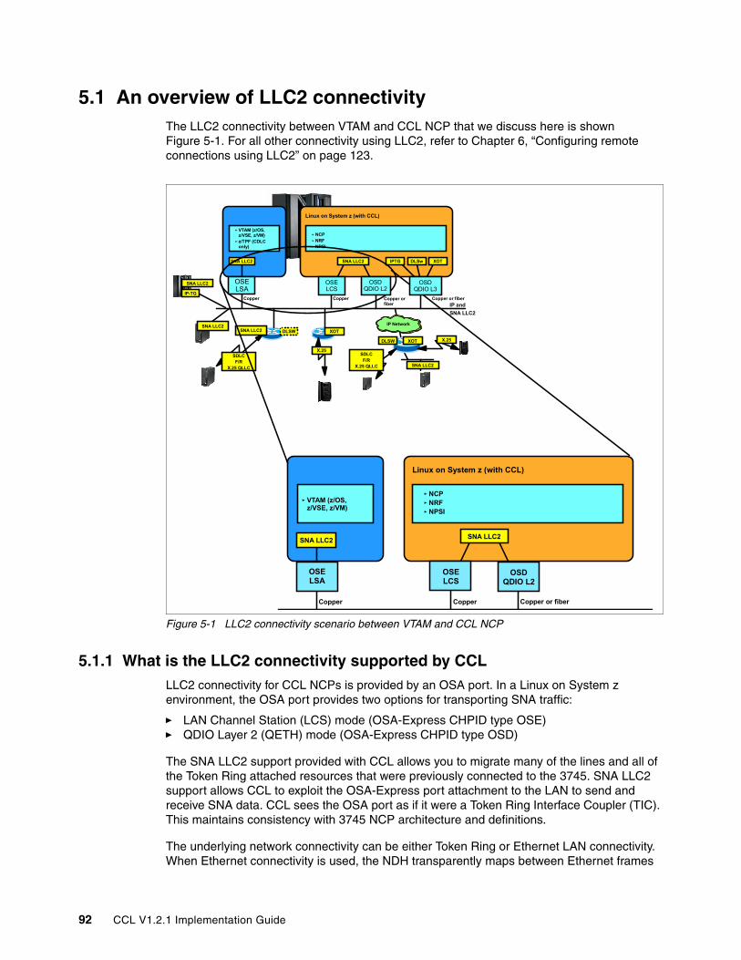
1.3.2 LLC2 connectivityLogical Link Control type 2 (LLC2) provides VTAM-to-CCL NCP and BNN connectivity, and is supported with CCL using one of the following two methods:
1. LAN Channel Station mode (LCS)2. Layer 2 mode
VTAM uses Link Service Architecture (LSA) support via an OSA port to communicate at LLC2 level on the LAN with a CCL NCP.
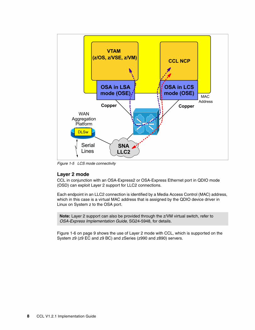
LCS modeCCL in conjunction with an OSA Ethernet or Token Ring port in LCS mode can support LLC2 connections.
Each endpoint in an LLC2 connection is identified by a Media Access Control (MAC) address, which in this case is a MAC address that is assigned via OSA/SF to the OSA port.
Figure 1-5 on page 8 shows the use of LCS mode with CCL, which is supported on the System z9 (z9 EC and z9 BC), zSeries (z990, z890, z900, and z800), and S/390 G5/G6 servers.
NCP
VTAM(z/OS, z/VSE,
or z/VM)z/TPF
OSA Express2 (OSN mode)
CDLC
QDIO QDIO
CDLC
CCL
Chapter 1. Introduction 7
Figure 1-5 LCS mode connectivity
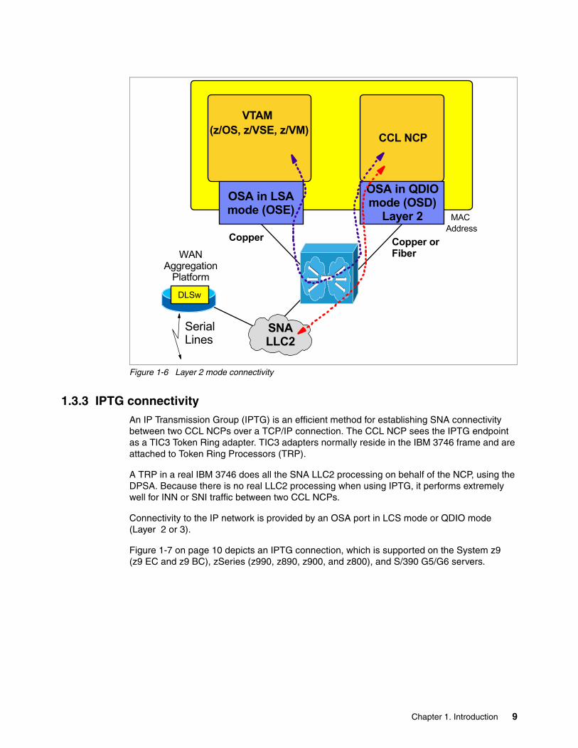
Layer 2 modeCCL in conjunction with an OSA-Express2 or OSA-Express Ethernet port in QDIO mode (OSD) can exploit Layer 2 support for LLC2 connections.
Each endpoint in an LLC2 connection is identified by a Media Access Control (MAC) address, which in this case is a virtual MAC address that is assigned by the QDIO device driver in Linux on System z to the OSA port.
Figure 1-6 on page 9 shows the use of Layer 2 mode with CCL, which is supported on the System z9 (z9 EC and z9 BC) and zSeries (z990 and z890) servers.
Note: Layer 2 support can also be provided through the z/VM virtual switch, refer to OSA-Express Implementation Guide, SG24-5948, for details.
VTAM (z/OS, z/VSE, z/VM)
OSA in LSA mode (OSE)
OSA in LCS mode (OSE)
CCL NCP
Copper
SNA LLC2
Copper
WAN Aggregation
Platform
Serial Lines
MAC Address
DLSw
8 CCL V1.2.1 Implementation Guide
Figure 1-6 Layer 2 mode connectivity
1.3.3 IPTG connectivityAn IP Transmission Group (IPTG) is an efficient method for establishing SNA connectivity between two CCL NCPs over a TCP/IP connection. The CCL NCP sees the IPTG endpoint as a TIC3 Token Ring adapter. TIC3 adapters normally reside in the IBM 3746 frame and are attached to Token Ring Processors (TRP).
A TRP in a real IBM 3746 does all the SNA LLC2 processing on behalf of the NCP, using the DPSA. Because there is no real LLC2 processing when using IPTG, it performs extremely well for INN or SNI traffic between two CCL NCPs.
Connectivity to the IP network is provided by an OSA port in LCS mode or QDIO mode (Layer 2 or 3).
Figure 1-7 on page 10 depicts an IPTG connection, which is supported on the System z9 (z9 EC and z9 BC), zSeries (z990, z890, z900, and z800), and S/390 G5/G6 servers.
VTAM (z/OS, z/VSE, z/VM)
OSA in LSA mode (OSE)
OSA in QDIO mode (OSD)
Layer 2
CCL NCP
Copper or Fiber
SNA LLC2
Copper
WAN Aggregation
Platform
Serial Lines
MAC Address
DLSw
Chapter 1. Introduction 9
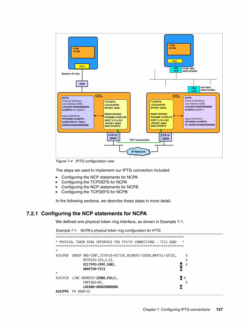
Figure 1-7 IPTG connectivity
The IPTG TCP/IP connection can optionally be secured (encrypted) using stunnel technology provided by Linux.
Additionally, control of TCP port numbers can be enforced at both endpoints via firewalls between business partners.
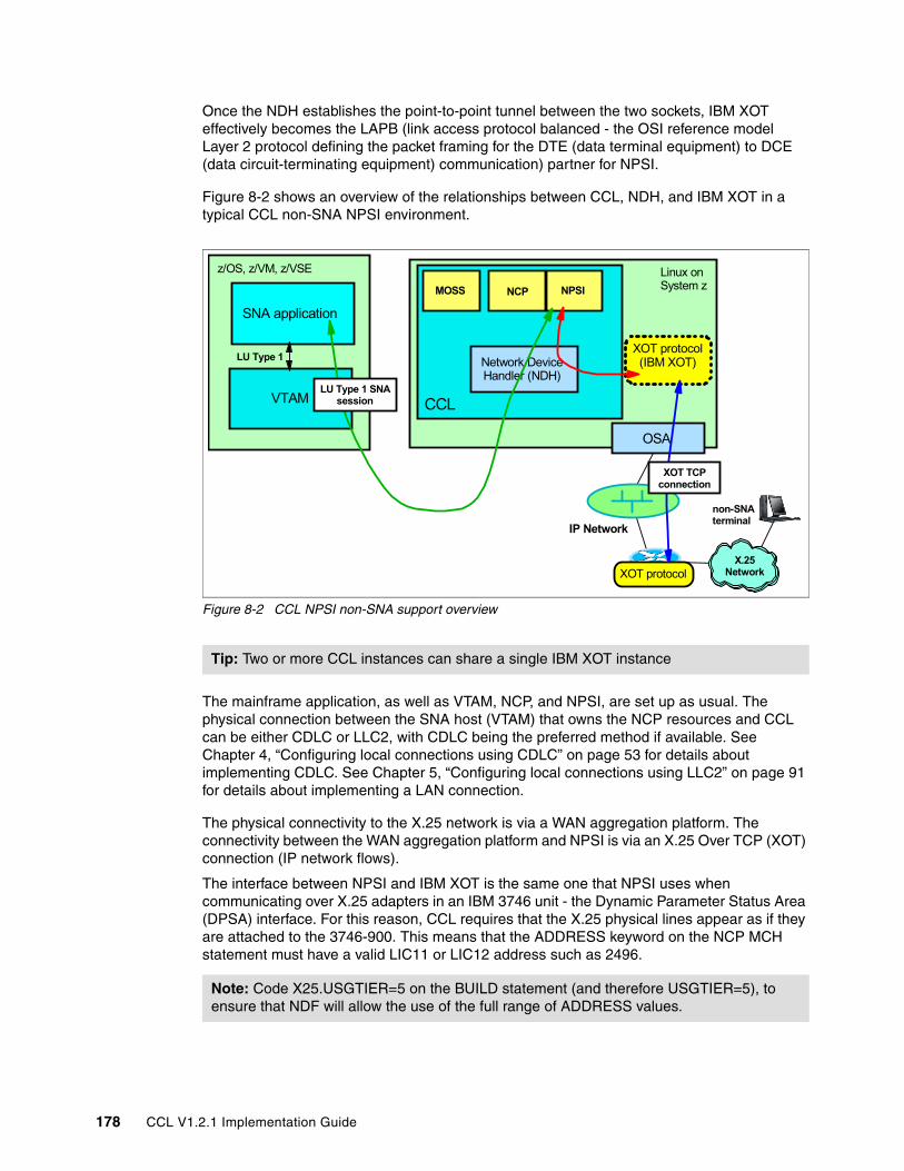
1.3.4 X.25 connectivityCCL supports the connection of X.25 lines and devices to NCP Packet Switching Interface (NPSI), which runs with the NCP inside CCL Engine. Since there is no OSA feature that supports the physical connectivity needed for X.25 line attachment, this solution relies on industry standard routers to provide the physical X.25 connectivity. This means the router must be configured to use the X.25 over TCP/IP (XOT) to carry the X.25 packets over the IP network.
XOT is an open standard and defined in RFC 1613 Cisco Systems X.25 over TCP (XOT).
CCL does not support the XOT protocol itself but does provide an interface to send and receive X.25 packets through NDH sockets. You need an additional software component (IBM X.25 over TCP/IP for Communication Controller for Linux) to terminate the XOT protocol within the Linux on System z image.
Physical connectivity to the X.25 network is via a WAN aggregation platform. Connectivity between WAN aggregation platform and NPSI is via an X.25 Over TCP/IP (XOT) connection, as shown in Figure 1-8 on page 11.
Connectivity to the IP network is provided by an OSA port in LCS mode or QDIO mode (Layer 2 or 3), on the System z9 (z9 EC and z9 BC), zSeries (z990, z890, z900, and z800), and S/390 G5/G6 servers.
Note: IPTG in combination with the CDLC connectivity to VTAM provides up to 6 times better throughput than two IBM 3745 (INN or SNI) NCPs connected via Token Ring.
NCP
IPTG
LCS or QDIO
CCL
NCP
IPTG
IP Network
CCL
LCS or QDIO
10 CCL V1.2.1 Implementation Guide
Figure 1-8 X.25 connectivity
IBM provides the XOT protocol support for Linux on System z as a separately priced feature called IBM X.25 over TCP/IP for Communication Controller for Linux (IBM XOT), feature code 5724-O43.
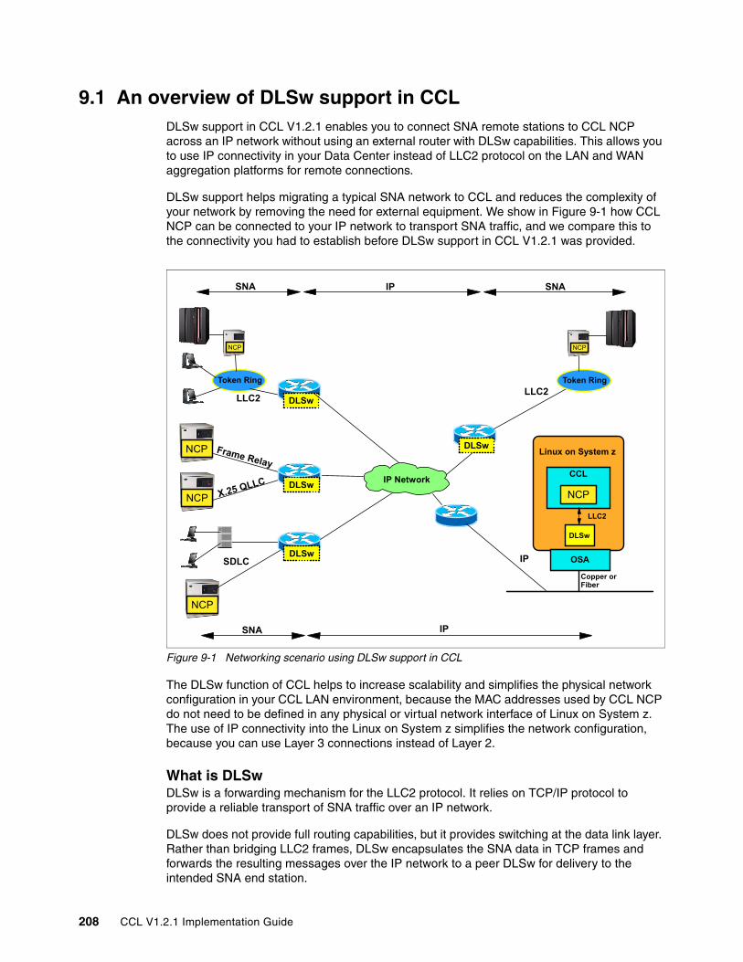
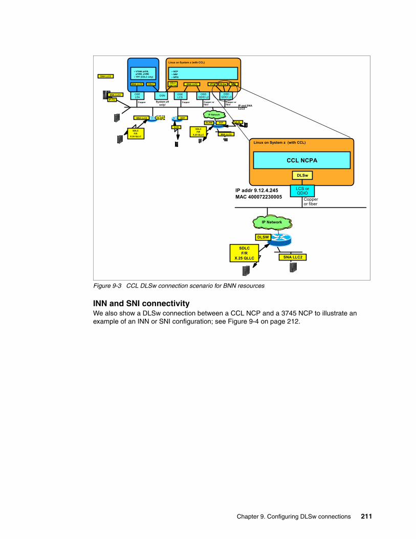
1.3.5 DLSw connectivityThe CCL DLSw component provides a means for LAN traffic to be routed over TCP/IP to industry standard DLSw routers. Those routers can forward the SNA frames to the SNA partner nodes over a variety of data link types. Only a single instance of the CCL DLSw can be run in each Linux image, regardless of the number of CCL Engines (NCPs) running in that Linux image.
CCL DLSw is a forwarding mechanism for the LLC2 protocol. It relies on the switch-to-switch protocol (SSP) and TCP/IP to provide a reliable transport of SNA traffic over an IP network. DLSw does not provide full routing capabilities, but does provide switching at the data link layer. Rather than bridging LLC2 frames, DLSw encapsulates the data in TCP/IP frames and forwards them to a peer DLSw for delivery to their intended end-station addresses.
CCL DLSw provides an interface to send and receive packets through NDH sockets for communication with the CCL NCP.
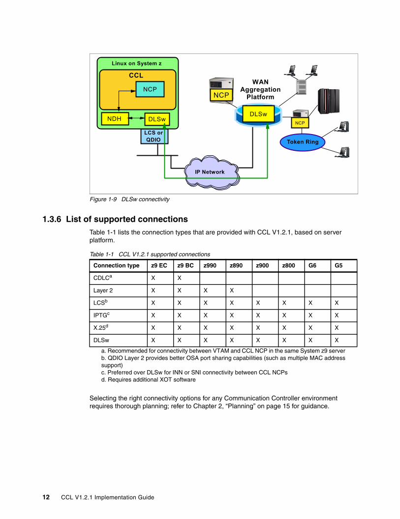
Physical connectivity for the serial lines is via a WAN aggregation platform. Connectivity between WAN aggregation platform with DLSw and DLSw within the Linux on System z image is shown in Figure 1-9 on page 12.
Connectivity to the IP network is provided by an OSA port in LCS mode or QDIO mode (Layer 2 or 3), on the System z9 (z9 EC and z9 BC), zSeries (z990, z890, z900, and z800), and S/390 G5/G6 servers.
IP Network
XOT
X.25 Network
SNA Terminal (QLLC)
non-SNA Terminal
WAN Aggregation
Platform
LCS orQDIO
Linux on System z
CCL
NCPNPSI
XOTNDH
Chapter 1. Introduction 11
Figure 1-9 DLSw connectivity
1.3.6 List of supported connectionsTable 1-1 lists the connection types that are provided with CCL V1.2.1, based on server platform.
Table 1-1 CCL V1.2.1 supported connections
Selecting the right connectivity options for any Communication Controller environment requires thorough planning; refer to Chapter 2, “Planning” on page 15 for guidance.
IP Network
DLSw
NCP
WAN Aggregation
Platform
Token Ring
NCP
LCS orQDIO
Linux on System z
CCL
NCP
DLSwNDH
Connection type z9 EC z9 BC z990 z890 z900 z800 G6 G5
CDLCa
a. Recommended for connectivity between VTAM and CCL NCP in the same System z9 server
X X
Layer 2 X X X X
LCSb
b. QDIO Layer 2 provides better OSA port sharing capabilities (such as multiple MAC addresssupport)
X X X X X X X X
IPTGc
c. Preferred over DLSw for INN or SNI connectivity between CCL NCPs
X X X X X X X X
X.25d
d. Requires additional XOT software
X X X X X X X X
DLSw X X X X X X X X
12 CCL V1.2.1 Implementation Guide
1.4 Hardware and software supportThis section provides a list of the hardware and software required to support CCL V1.2.1.
Hardware requirements include:
� System z9 (z9 EC and z9 BC), zSeries (z990, z890, z900, and z800), and S/390 G5/G6
The number of IFL3 engines depends on workload and connectivity options. In general it is possible to migrate two heavily used IBM 3745s (CCU utilization over 70% each) to one zSeries IFL engine and up to five IBM 3745s to one System z9 IFL engine.
� OSA port requirement:
– Copper-based ports for SNA LLC2 (LCS) - can be used on all hardware levels– Fiber optic or copper ports for SNA LLC2 (QDIO Layer-2) - z9 EC, z9 BC, z990, or
z890 only– Fiber optic or copper ports for SNA over IP, such as IPTG, XOT, DLSw (use QDIO
Layer-3, Layer-2, or LCS)– OSN port for CDLC connectivity - System z9 and OSA-Express2 Ethernet features
only (excluding the 10 Gigabit Long Reach feature)
� Memory requirements
The memory required per CCL engine is 20 MB. Usual memory requirements for Linux on System z is 256 - 512 MB. This depends on distribution, packages, and kernel level.
� DASD requirements
The DASD required for CCL is 50 MB. DASD for CCL traces, dumps, logs, NCP load modules is 80 - 100 MB per CCL engine. Usual DASD requirements for Linux on System z are equivalent to two 3390-3 DASD volumes. Use the Linux Logical Volume Manager (LVM) to group the volumes together.
Software requirements include:
� SUSE LINUX Enterprise Server 8 for IBM zSeries and IBM S/390 (SLES8), kernel 2.4.21
– Minimum level supported: Service Pack 4 (SLES8 + SP4)
� SUSE LINUX Enterprise Server 9 for IBM zSeries and IBM S/390 (SLES9), kernel 2.6.5
– Minimum level supported: Service Pack 1 (SLES9 + SP1)
� Red Hat Enterprise Linux AS 4 (RHEL4), kernel 2.6.9
IBM is working with its Linux distribution partners to ensure that this function will be provided in future kernel 2.6 distribution releases or service updates.
� Generation and utility support for the NCP that is still provided through Advanced Communication Function (ACF) System Support Program (SSP):
Additionally, the System Support Program (SSP), Network Routing Facility (NRF) and NTuneMON products are also supported by CCL at the release level supported by the corresponding NCP.
For availability of further distributions supporting CCL V1.2.1 functions and specific package requirements on top of available distributions, refer to:
http://www.ibm.com/software/network/ccl
Chapter 3, “Preparing and installing” on page 31, provides more detailed information regarding hardware and software requirements.
1.5 Performance comparisonA CCL environment running on a System z9 server can deliver significantly improved throughput (transactions per second) and response times as compared to a similar NCP-based workload running on a real IBM 3745/46 environment.
In some cases, CCL can deliver between 5 and 6 times more transactions per second than an IBM 3745/46 31A configuration. With CCL V1R2 running in a System z9, it is possible to consolidate INN or SNI workloads from up to five IBM 3745 31A configurations (CCU utilization at around 70%) into a single System z9 IFL engine.
OSN connectivity between VTAM and a CCL NCP improves performance about 40% as compared to a shared LAN between VTAM and a CCL NCP, using LLC2.
IPTG connectivity between two CCL NCPs also improves performance as compared to SNA LLC2 over a shared LAN between the two CCL NCPs. An INN or SNI environment using OSN between VTAM and the CCL NCPs and IPTG between the two CCL NCPs performs about 30% better than a similar environment using SNA LLC2 over a shared LAN between the two NCPs.
Use of QDIO Layer 2 for SNA LLC2 traffic between a CCL NCP and a LAN does not appear to have a performance benefit over LCS connectivity. However, use of QDIO Layer 2 provides much improved OSA port sharing capabilities (such as multiple MAC address support), and the opportunity to make use of fiber-optic LAN ports, such as Gigabit and 10 Gigabit OSA-Express2 ports.
When comparing CCL CPU utilization to IBM 3745 CCU utilization, many factors influence the comparison. The most significant factor is the hardware configuration of the IBM 3745/46 environment – in particular whether TIC2 or TIC3 interfaces are used for LAN connectivity.
For more details, refer to CCL V1R2 – System z9 and zSeries CPU Capacity Planning, at:
Note: A CCL CPU utilization estimate based on existing IBM 3745 CCU utilization should not be made without a clear understanding of the current IBM 3745/46 hardware configuration.
When deciding to migrate from your IBM Communication Controller (3745/46) environment, you must face the initial challenge of knowing what functions your Communication Controllers are currently providing.
In this chapter we provide a process for reviewing, optimizing, and planning the migration of your Communication Controller environment. We describe a methodology used to plan a CCL V1.2.1 implementation project.
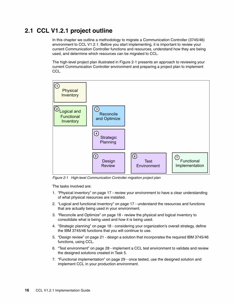
2.1 CCL V1.2.1 project outlineIn this chapter we outline a methodology to migrate a Communication Controller (3745/46) environment to CCL V1.2.1. Before you start implementing, it is important to review your current Communication Controller functions and resources, understand how they are being used, and determine which resources can be migrated to CCL.
The high-level project plan illustrated in Figure 2-1 presents an approach to reviewing your current Communication Controller environment and preparing a project plan to implement CCL.
Figure 2-1 High-level Communication Controller migration project plan
The tasks involved are:
1. “Physical inventory” on page 17 - review your environment to have a clear understanding of what physical resources are installed.
2. “Logical and functional inventory” on page 17 - understand the resources and functions that are actually being used in your environment.
3. “Reconcile and Optimize” on page 18 - review the physical and logical inventory to consolidate what is being used and how it is being used.
4. “Strategic planning” on page 18 - considering your organization’s overall strategy, define the IBM 3745/46 functions that you will continue to use.
5. “Design review” on page 21 - design a solution that incorporates the required IBM 3745/46 functions, using CCL.
6. “Test environment” on page 28 - implement a CCL test environment to validate and review the designed solutions created in Task 5.
7. “Functional implementation” on page 29 - once tested, use the designed solution and implement CCL in your production environment.
Test Environment
Design Review
Physical Inventory
Reconcile and Optimize
Logical andFunctional Inventory
Strategic Planning
Functional Implementation
1
2 3
4
6 75
16 CCL V1.2.1 Implementation Guide
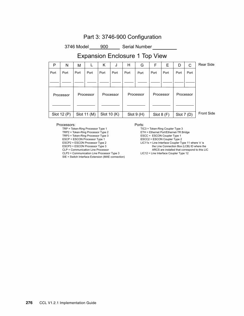
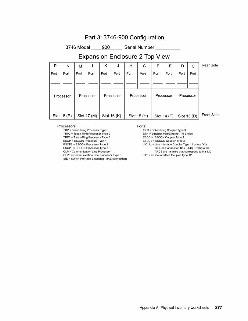
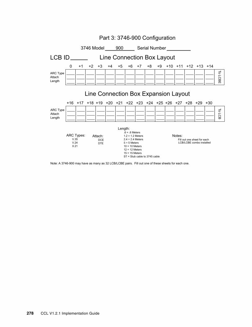
2.2 Physical inventory The overall goal of the physical inventory is to identify and verify what you have installed in your Communication Controller environment. Through on-site visual inspections, identify all Communication Controllers and their installed interfaces. The worksheets located in Appendix A, “Physical inventory worksheets” on page 267 may be used to guide the inventory process.
CCL V1.2.1 emulates a 3745/46 model 31A (with 16 MB of memory); however, NCPs from any 3745/46 model are supported. Even older model Communication Controllers (such as IBM 3705, 3720, and 3725) should be considered when moving to CCL.
It is important to carefully explore and clearly understand the equipment that you have installed, as well as how it is being used.
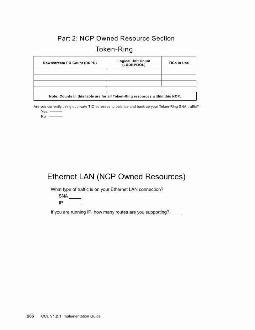
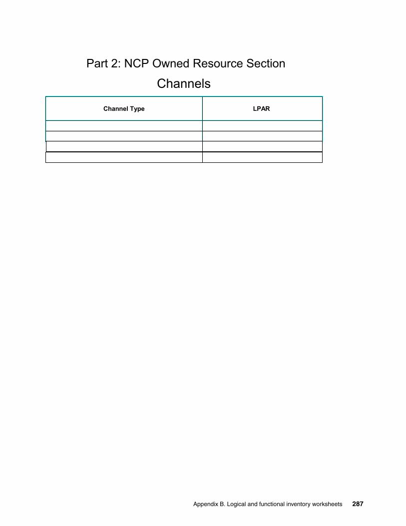
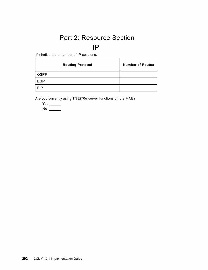
2.3 Logical and functional inventory While the overall goal of the physical inventory is to identify and verify what you have installed in your Communication Controllers, the goal of the logical and functional inventory is to understand the resources and functions that are actually being used in your Communication Controller environment, and how they are being used.
In 2.4, “Reconcile and Optimize” on page 18, the logical and functional inventory is used along with the physical inventory to identify Communication Controller hardware that is no longer needed. The logical and functional inventory also provides important information on how Communication Controllers are currently being used for 2.5, “Strategic planning” on page 18.
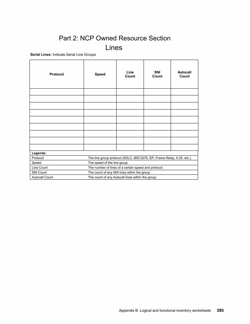
Your logical and functional inventory should start with a review of your NCP generation statements. For those Communication Controller resources that are still in use, understand how they serve the needs of your organization. Start by identifying those functions that can be migrated to CCL V1.2.1, such as:
� NCP-related functions:
– Boundary function lines, INN lines, SNI lines
– Use of duplicate TIC MAC addressing for availability and scalability
– XRF, NRF, NPSI support
– NTuneMON, NPA-LU
� Functions that are not supported by CCL and cannot be migrated are:
– NTO, XI, NSI, and NSF
– Network Node Processor functions (3746-900 or 3746-950)
The worksheets located in Appendix B, “Logical and functional inventory worksheets” on page 281 may be used to guide the inventory process.
Note: In this redbook we describe the methodology to migrate IBM Communication Controllers running NCP to CCL V1.2.1. If you are planning to migrate other IBM Communication Controllers such as NNP or 3746-950, refer to IBM Communication Controller Migration Guide, SG24-6298.
Chapter 2. Planning 17
2.4 Reconcile and OptimizeReview the physical inventory information in light of what you learned from the logical and functional inventory process, by doing the following:
� Identify physical interfaces that are installed, but no longer in use.
� Identify any installed software components (such as NRF or NTO) that are no longer being used.
� Clean up NCP definitions accordingly.
The worksheets located in Appendix C, “Reconciled logical and physical inventory worksheet” on page 293 may be used to guide you through this process.
2.5 Strategic planningThe output from the reconcile and optimize step provides a solid foundation for your Communication Controller strategic planning. Essentially, it defines the “as is” of your Communication Controller environment, while your strategic plan should establish the “to be” or target environment.
Your Communication Controller strategic plan should include the following tasks:
� Review your current physical and logical Communication Controller environment.
� Review the functional roles that your Communication Controllers play.
� Identify workloads that can be moved off the SNA network via SNA/IP integration technologies, such as Enterprise Extender.
� Identify which functions can be migrated to CCL V1.2.1.
� Determine which NCPs will move to CCL and in which order.
� Identify which NCPs can be consolidated when moving to CCL.
� Determine which WAN or serial lines can be terminated. For example, remote locations that are already connected through an IP network to the data center - DLSw or IPTG technology over the IP network can be used instead.
� Identify which WAN or serial lines are supported through WAN aggregation platforms. In this case you must:
– Define how many serial ports will be necessary to migrate
– Determine the number of routers and/or switches needed
– Provide redundancy for WAN termination if required
� Include a high availability strategy - levels of redundancy and fail-over capabilities
Tip: Tools such as NTuneMON, NetView®, and NPM can be helpful in determining whether resources are still in use.
Note: Formulate your strategy with respect to the future role of the Communication Controllers in your environment.
18 CCL V1.2.1 Implementation Guide
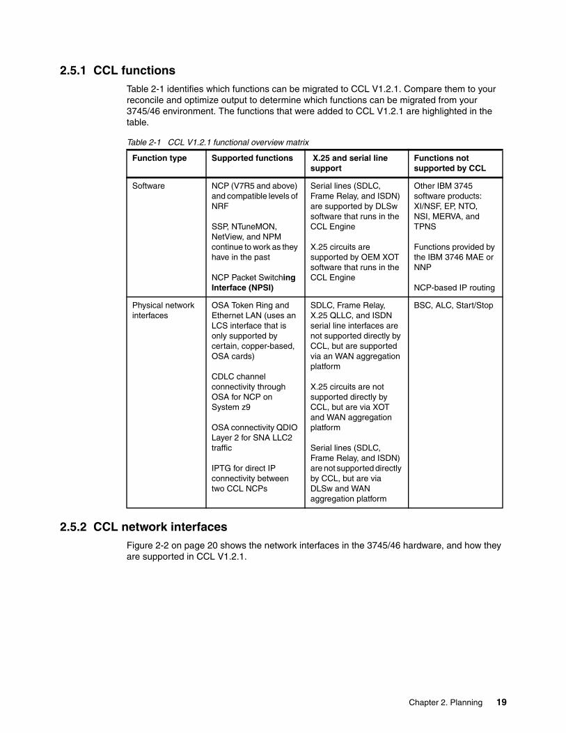
2.5.1 CCL functionsTable 2-1 identifies which functions can be migrated to CCL V1.2.1. Compare them to your reconcile and optimize output to determine which functions can be migrated from your 3745/46 environment. The functions that were added to CCL V1.2.1 are highlighted in the table.
Table 2-1 CCL V1.2.1 functional overview matrix
2.5.2 CCL network interfacesFigure 2-2 on page 20 shows the network interfaces in the 3745/46 hardware, and how they are supported in CCL V1.2.1.
Function type Supported functions X.25 and serial line support
Functions not supported by CCL
Software NCP (V7R5 and above) and compatible levels of NRF
SSP, NTuneMON, NetView, and NPM continue to work as they have in the past
NCP Packet Switching Interface (NPSI)
Serial lines (SDLC, Frame Relay, and ISDN) are supported by DLSw software that runs in the CCL Engine
X.25 circuits are supported by OEM XOT software that runs in the CCL Engine
Other IBM 3745 software products: XI/NSF, EP, NTO, NSI, MERVA, and TPNS
Functions provided by the IBM 3746 MAE or NNP
NCP-based IP routing
Physical network interfaces
OSA Token Ring and Ethernet LAN (uses an LCS interface that is only supported by certain, copper-based, OSA cards)
CDLC channel connectivity through OSA for NCP on System z9
OSA connectivity QDIO Layer 2 for SNA LLC2 traffic
IPTG for direct IP connectivity between two CCL NCPs
SDLC, Frame Relay, X.25 QLLC, and ISDN serial line interfaces are not supported directly by CCL, but are supported via an WAN aggregation platform
X.25 circuits are not supported directly by CCL, but are via XOT and WAN aggregation platform
Serial lines (SDLC, Frame Relay, and ISDN) are not supported directly by CCL, but are via DLSw and WAN aggregation platform
BSC, ALC, Start/Stop
Chapter 2. Planning 19
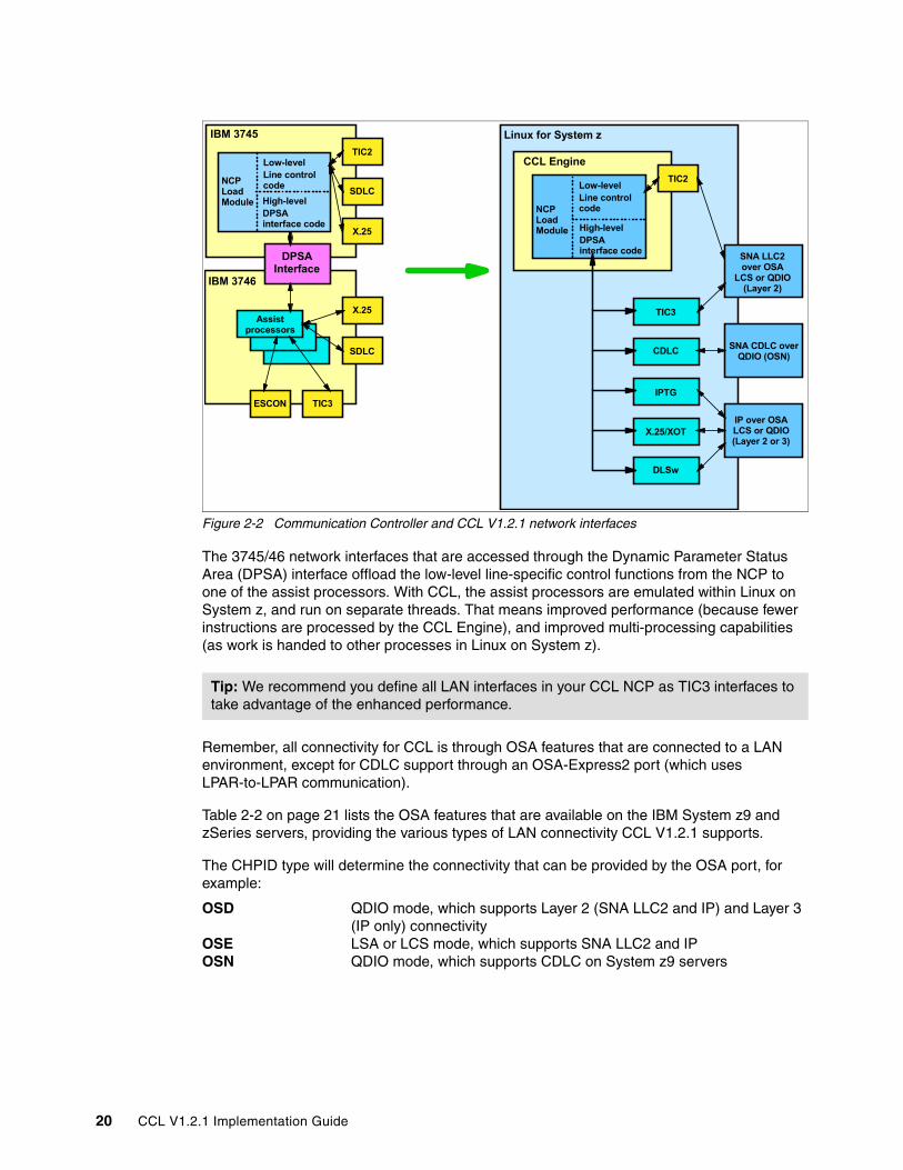
Figure 2-2 Communication Controller and CCL V1.2.1 network interfaces
The 3745/46 network interfaces that are accessed through the Dynamic Parameter Status Area (DPSA) interface offload the low-level line-specific control functions from the NCP to one of the assist processors. With CCL, the assist processors are emulated within Linux on System z, and run on separate threads. That means improved performance (because fewer instructions are processed by the CCL Engine), and improved multi-processing capabilities (as work is handed to other processes in Linux on System z).
Remember, all connectivity for CCL is through OSA features that are connected to a LAN environment, except for CDLC support through an OSA-Express2 port (which uses LPAR-to-LPAR communication).
Table 2-2 on page 21 lists the OSA features that are available on the IBM System z9 and zSeries servers, providing the various types of LAN connectivity CCL V1.2.1 supports.
The CHPID type will determine the connectivity that can be provided by the OSA port, for example:
OSD QDIO mode, which supports Layer 2 (SNA LLC2 and IP) and Layer 3 (IP only) connectivity
OSE LSA or LCS mode, which supports SNA LLC2 and IPOSN QDIO mode, which supports CDLC on System z9 servers
Tip: We recommend you define all LAN interfaces in your CCL NCP as TIC3 interfaces to take advantage of the enhanced performance.
Assist processors
TIC2
SDLC
X.25
X.25
SDLC
TIC3ESCON
IBM 3745
IBM 3746
DPSA Interface
NCP Load Module
Low-levelLine control code
High-levelDPSA interface code
NCP Load Module
Low-levelLine control code
High-levelDPSA interface code
TIC3
CDLC
IPTG
X.25/XOT
TIC2
SNA LLC2 over OSA
LCS or QDIO (Layer 2)
SNA CDLC over QDIO (OSN)
IP over OSA LCS or QDIO (Layer 2 or 3)
Linux for System z
CCL Engine
DLSw
20 CCL V1.2.1 Implementation Guide
Table 2-2 OSA-Express and OSA-Express2 features
Note that if you plan to implement CCL V1.2.1 on your S/390 G5/G6, feature codes 2340 (OSA-Express Fast Ethernet) and 5201 (OSA2 ENTR) can be used. These features only support a CHPID type of OSE for LSA and LCS modes.
2.6 Design reviewThe next task is to design the CCL V1.2.1 environment with the required functions from the current Communication Controller environment that will be migrated. During the design process, you should also define how high availability will be achieved in your environment.
2.6.1 High availability Ensure that the high availability characteristics currently used in your Communication Controller environment are preserved, such as XRF, SSCP takeover, and Twin CCU support. Table 2-3 on page 22 compares the high availability and backup functions provided by the current Communication Controller environment (3745/46 and NCP) and the solutions provided by CCL V1.2.1.
3364 n/a n/a 40 48 30/48 48 LC Duplex SM 9 µm OSD or OSN
MCPf
OSA Express2GbE SX
3365 n/a n/a 40 48 30/48 48 LC Duplex MM 62.5 µm OSD or OSN
MM 50 µm
OSA-Express21000BASE-T
3366 n/a n/a n/a n/a 30/48 48 RJ 45 UTP Cat5 OSD, OSE, or OSN
OSA-Express210 GbE LR
3368 n/a n/a 20 24 15/24 24 SC Duplex SM 9 µm OSD
Chapter 2. Planning 21
Table 2-3 CCL V1.2.1 high availability options
You also need to determine the number of CCL Engines required to migrate your resources and where to implement them. From a high availability and backup perspective, you should always duplicate every resource to avoid single-points of failure (see Figure 2-3 on page 23).
3745/46 NCP (all models) CCL NCP
Single CCU mode - Only one CCU is installed in the Communication Controller.
Each CCL Engine active essentially runs as a single CCU mode configuration.
Twin CCU in dual mode - Two CCUs are installed in the Communication Controller, but channel and line adapters are dedicated to one CCU or the other.
Similar results can be achieved by starting up a unique CCL Engine for each NCP that you want to run (either in the same Linux on System z or in different Linux on System z images).
Twin CCU in standby mode - Two CCUs are installed in the Communication Controller, but all channel and line adapters are dedicated to one CCU; the other CCU is either down or idle, ready to back up the working CCU.
CCL does not support a twin CCU in standby mode configuration. However, the twin CCU in standby mode configuration is implemented within CCL itself because CCL automatically attempts to restart a failing CCL NCP by starting up another CCL Engine using the same NCP load module (Auto Dump/Load switch must be on).
Twin CCU in backup mode - Two CCUs are installed in the Communication Controller, and channel and line adapters are associated with one CCU or the other; bus switching between the CCUs is supported for certain types of failures (power supply and CCU failures).
CCL does not support a twin CCU in backup mode configuration. However, redundant hardware (power supplies and CPUs) is provided by the System z9 and zSeries hardware, and is therefore available to the Linux operating system used to run CCL. If Auto Dump/Load switch is set, CCL will automatically restart a failing CCL NCP by starting up another CCL Engine using the same load module (and other parameters).
Multi Link Transmission Group (MLTG) - The ability to group more than one subarea link station associated with a single TG.
MLTG over multiple LAN adapters is supported. Note: MLTG is not supported by DLSwtechnology.
EXtended Recovery Facility (XRF) - Provides an efficient means to switch SNA dependent LU-LU sessions from the active to the alternate subsystem without terminating the sessions or requiring the end terminal user to log on again.
XRF is supported by CCL.
SSCP takeover: When a SSCP-NCP session is terminated, NCP can transfer its control to another SSCP, which also takes over all NCPs dependent LUs.
SSCP takeover is supported by CCL.
Redundant CCL/NCPs with duplicate TR MAC addresses.
Supported by CCL. Similar capabilities can be deployed for Ethernet by combining VLAN technology and DLSW technology.
22 CCL V1.2.1 Implementation Guide
Figure 2-3 Basic concept - high availability
This example shows two CCL Engines for each NCP. The CCL Engines should be loaded in two different Linux on System z images, and the VTAM-to-NCP connections should be duplicated. The dotted lines and boxes in this example indicate hot-standby NCPs and connections.
2.6.2 CCL NCP design scenarioAfter all the requirements and information are compiled and reviewed, the next step is to evaluate the connectivity options provided by CCL. This will aid in determining which features and resources will be migrated to the CCL V1.2.1 environment, as well as connectivity to the network.
To walk you through this process, we have defined a common IBM 3745/46 environment (see Figure 2-4 on page 24), with various types of connectivity. Based on this common IBM 3745/46 environment we show the options available with CCL V1.2.1.
CCL Engine NCPA
CCL Engine NCPB
VTAM1 VTAM2
CCL Engine NCPB
CCL Engine NCPA
Chapter 2. Planning 23
Figure 2-4 Common IBM 3745/45 environment
To simplify this process, we will approach our design scenario based on the connection types supported by CCL V1.2.1. We show single-connection configurations in our examples for discussion purposes only. As mentioned, you should always duplicate every connection to avoid single points of failure.
In the remainder of this section, we discuss the following:
� Local connectivity options - VTAM-to-NCP connections� BNN connectivity options - LAN and WAN connections� INN and SNI connectivity options - WAN connections� X.25 connectivity options - X.25 network connections
Local connectivity optionsCCL V1.2.1 can be connected to the local VTAM environment in two ways:
� CDLC attached
CDLC-attached connectivity for CCL NCPs is provided by the Open Systems Adapter for NCP (OSN). This option is only available on the System z9 with OSA-Express2 Ethernet features (excluding the 10 Gigabit Long Reach feature). Use this type of connection if the VTAM or z/TPF host image resides in the same physical System z9 server where the Linux image (in which the CCL NCP is executing). The NCP is generated and loaded as a local attached NCP. For further information about this type of connection, refer to Chapter 4, “Configuring local connections using CDLC” on page 53.
� LLC 2 attached
LAN network connectivity for CCL NCPs is provided by the Open Systems Adapter (OSA) hardware running in QETH (QDIO Ethernet) using the Layer 2 function or LAN Channel Station (LCS) mode. The NCP is generated and loaded as a remote attached NCP. To connect the NCP, the local VTAM must have a Link Services Architecture (LSA) connection. For further information about this type of connection, refer to Chapter 5, “Configuring local connections using LLC2” on page 91.
Token Ring
SNI
Corporation
IBM 3745/46 NCP
VTAM(z/OS, z/VSE, z/VM)
Business Partner
NCP VTAM z/TPF
VTAM(z/OS, z/VSE, z/VM)
X.25
SNA Device (QLLC)
non-SNA Device
INN
NCP
IBM 3745/46
IBM 3745/46
SNA Device
z/TPF
BNN
24 CCL V1.2.1 Implementation Guide
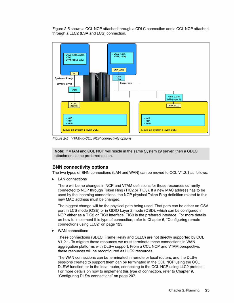
Figure 2-5 shows a CCL NCP attached through a CDLC connection and a CCL NCP attached through a LLC2 (LSA and LCS) connection.
Figure 2-5 VTAM-to-CCL NCP connectivity options
BNN connectivity optionsThe two types of BNN connections (LAN and WAN) can be moved to CCL V1.2.1 as follows:
� LAN connections
There will be no changes in NCP and VTAM definitions for those resources currently connected to NCP through Token Ring (TIC2 or TIC3). If a new MAC address has to be used by the incoming connections, the NCP physical Token Ring definition related to this new MAC address must be changed.
The biggest change will be the physical path being used. That path can be either an OSA port in LCS mode (OSE) or in QDIO Layer 2 mode (OSD), which can be configured in NCP either as a TIC2 or TIC3 interface. TIC3 is the preferred interface. For more details on how to implement this type of connection, refer to Chapter 6, “Configuring remote connections using LLC2” on page 123.
� WAN connections
These connections (SDLC, Frame Relay and QLLC) are not directly supported by CCL V1.2.1. To migrate these resources we must terminate these connections in WAN aggregation platforms with DLSw support. From a CCL NCP and VTAM perspective, these resources will be reconfigured as LLC2 resources.
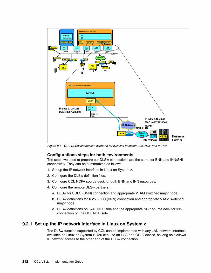
The WAN connections can be terminated in remote or local routers, and the DLSw sessions created to support them can be terminated in the CCL NCP using the CCL DLSW function, or in the local router, connecting to the CCL NCP using LLC2 protocol. For more details on how to implement this type of connection, refer to Chapter 9, “Configuring DLSw connections” on page 207.
Note: If VTAM and CCL NCP will reside in the same System z9 server, then a CDLC attachment is the preferred option.
OSN
CDLC
VTAM (z/OS, z/VSE, z/VM)z/TPF (CDLC only)
System z9 only
Copper only
OSELSA
SNA LLC2
VTAM (z/OS, z/VSE, z/VM)
SNA LLC2CDLC
(QETH)
NCPNRFNPSI
Linux on System z (with CCL)
NCPNRFNPSI
Linux on System z (with CCL)
LPAR-to-LPAR
OSE (LCS)OSD (Layer 2)
Chapter 2. Planning 25
Figure 2-6 shows the possible BNN connections through OSA-Express LCS mode, OSA Express QDIO Layer 2 mode, and DLSw connections terminating in the CCL DLSw function, while migrating WAN resources to an WAN aggregation platform with DLSw.
Figure 2-6 BNN connections
INN and SNI connectivity optionsFrom a NCP perspective, all logical definitions related to the INN and SNI connections, such as PATH statements, SDLCST, Gateway definitions, and so on, will not change.
What must change are the physical connections. CCL V1.2.1 provides the following INN and SNI connection types:
� LLC2 connections
As described for BNN connectivity, this type of connection can be used for INN and SNI connections currently using LLC2 Token Ring, and the remaining WAN connections (SDLC, Frame Relay, and QLLC X.25). As mentioned earlier, the WAN connections must terminate in WAN aggregation platforms with DLSw. This connection type will be seen by NCP as LLC2 Token Ring connections.
To define these connections, you can use either an OSA in LCS mode (OSE), which can be configured as a TIC2 or TIC3 interface, or an OSA-Express in QDIO Layer 2 mode (OSD), configured as a TIC3 interface. For more details about this connection type, refer to Chapter 6, “Configuring remote connections using LLC2” on page 123.
� IPTG connections (Layer 3)
IPTG has been developed to work in a CCL environment to exchange INN and SNI traffic between two CCL NCPs over a IP connection. It is an optimized SNA connection that can properly prioritize traffic per SNA LU 6.2 Class of Service (COS), in conjunction with an IP
SNA LLC2
NCPNRFNPSI
Copper Copper or Fiber
Linux on System z (with CCL)
Copper or Fiber
IP and SNA LLC2
DLSw
SNA LLC2
SDLCF/R
X.25 QLLC
SNA LLC2
DLSW
IP Network
DLSW
SNA LLC2
OSELCS
OSDQDIO L2
OSE or OSDLayer 3 (IP)
26 CCL V1.2.1 Implementation Guide
network configured to use Type of Service (TOS). For more details about this connection type, refer to Chapter 7, “Configuring IPTG connections” on page 153.
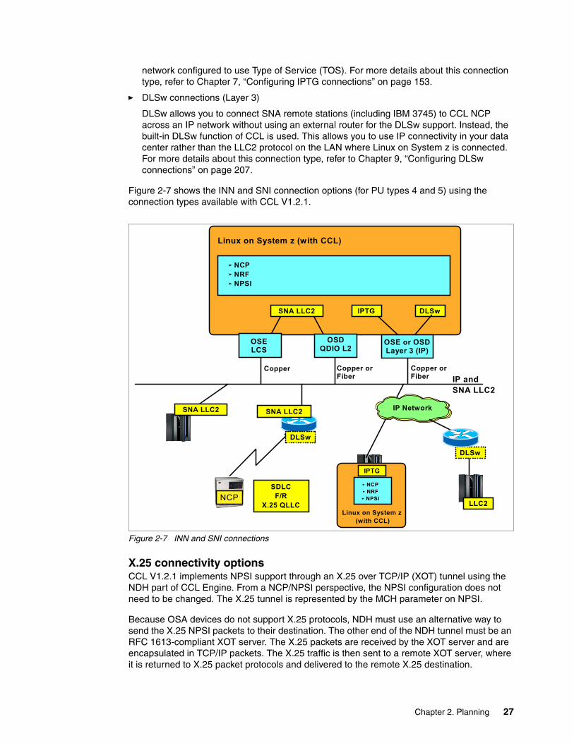
� DLSw connections (Layer 3)
DLSw allows you to connect SNA remote stations (including IBM 3745) to CCL NCP across an IP network without using an external router for the DLSw support. Instead, the built-in DLSw function of CCL is used. This allows you to use IP connectivity in your data center rather than the LLC2 protocol on the LAN where Linux on System z is connected. For more details about this connection type, refer to Chapter 9, “Configuring DLSw connections” on page 207.
Figure 2-7 shows the INN and SNI connection options (for PU types 4 and 5) using the connection types available with CCL V1.2.1.
Figure 2-7 INN and SNI connections
X.25 connectivity optionsCCL V1.2.1 implements NPSI support through an X.25 over TCP/IP (XOT) tunnel using the NDH part of CCL Engine. From a NCP/NPSI perspective, the NPSI configuration does not need to be changed. The X.25 tunnel is represented by the MCH parameter on NPSI.
Because OSA devices do not support X.25 protocols, NDH must use an alternative way to send the X.25 NPSI packets to their destination. The other end of the NDH tunnel must be an RFC 1613-compliant XOT server. The X.25 packets are received by the XOT server and are encapsulated in TCP/IP packets. The X.25 traffic is then sent to a remote XOT server, where it is returned to X.25 packet protocols and delivered to the remote X.25 destination.
IPTGSNA LLC2
NCPNRFNPSI
Copper Copper or Fiber
Copper or Fiber
SNA LLC2
SDLCF/R
X.25 QLLC
SNA LLC2
DLSw
IP Network
IP and SNA LLC2
Linux on System z (with CCL)
DLSw
NCP
DLSw
LLC2
NCPNRFNPSI
Linux on System z (with CCL)
IPTG
OSELCS
OSDQDIO L2
OSE or OSDLayer 3 (IP)
Chapter 2. Planning 27
IBM provides the XOT protocol support for Linux on System z as a separately priced feature called IBM X.25 over TCP/IP for Communication Controller for Linux (IBM XOT).
Figure 2-8 shows an X.25 (NPSI) environment using XOT and CCLV1.2.1.
Figure 2-8 CCL NPSI scenario
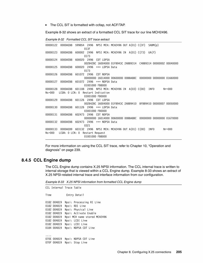
For more details about this connection type, refer to Chapter 8, “Configuring X.25 connections” on page 175.
2.7 Test environmentOnce you have designed your CCL solution, we recommend building a test environment where you can install, test, and verify each connection type that will be implemented in your production environment. With that test environment you can also try out recovery scenarios, document operational procedures, and learn how to proceed with the implementation tasks.
Our test environment is shown in Figure 2-9 on page 29. All scenarios found in this redbook were installed, tested, and verified using this environment. The physical environment consisted of multiple logical partitions (VTAMs and CCL NCPs), OSA-Express2 1000BASE-T ports on an IBM System z9 server, as well as a Cisco switch and routers for the network.
NCPNRFNPSI
Linux on System z (with CCL)
XOT
Copper or Fiber IP
XOT
X.25 Network
OSE or OSDLayer3 (IP)
SNA and Non-SNA X.25
resources
28 CCL V1.2.1 Implementation Guide
Figure 2-9 Our CCL V1.2.1 test environment
2.8 Functional implementationAfter your CCL solution has been designed and tested, you can proceed with the functional implementation planning step, which is to deploy CCL V1.2.1 in a way that causes minimum disruption to the production environment.
Once your CCL implementation is ready and you have determined the number of CCL NCPs that will be installed, prepare a detailed migration plan for each CCL NCP. During this step, avoid unnecessary disruptions to your production NCPs. The migration can be done in either one of the following ways:
� Deactivate the old NCP subarea and activate the new NCP with same subarea in CCL. This method requires the least amount of NCP changes and allows reuse of existing TIC MAC addresses by OSA ports.
� Or keep the old NCP subarea active, activate the new NCP with the new subarea in CCL, and migrate resources over time to the new NCP. Note that this method requires changes to SNA subarea path definitions, including the endpoints or business partners. It may also prevent you from reusing existing TIC MAC addresses in the new environment.
Based on the plans you prepared earlier, define the method for moving your consolidated WAN connections (serial lines) to the CCL NCP environment. If the existing IBM 3745/46 has TIC interfaces, a migration of WAN connections to WAN aggregation platforms could be considered before moving the NCP to CCL (this simplifies the move to CCL).
Careful project planning is essential. Each step should have a defined objective and a fallback plan to minimize the impact of unforeseen problems.
CDLC (QETH)
IPTG XOTSNA LLC2CDLCSNA LLC2
VTAM (z/OS, z/VSE, z/VM)z/TPF (CDLC only)
NCPNRFNPSI
Copper Copper Copper or Fiber
Copper or Fiber
SNA LLC2
IP Network
X.25
Non-SNA X.25 devices
SNA LLC2
XOT
SNA PU Type 4 NCP (running in CCL V1.2.1)
IPTG
SNA PU Type 2.0SNA PU Type 4 NCPSNA PU Type 5 VTAM
IP and SNA LLC2
Linux on System z (with CCL V1.2.1)
System z9
DLSw
DLSW
OSELSA
OSN OSELCS
OSDQDIO L2
OSDQDIO L3
DLSW
SDLCF/R
X.25 QLLC
LPAR-to-LPAR
Chapter 2. Planning 29
30 CCL V1.2.1 Implementation Guide
Chapter 3. Preparing and installing
In this chapter we show you how to install, and prepare the Communication Controller for Linux (CCL) environment. The chapter covers the following topics:
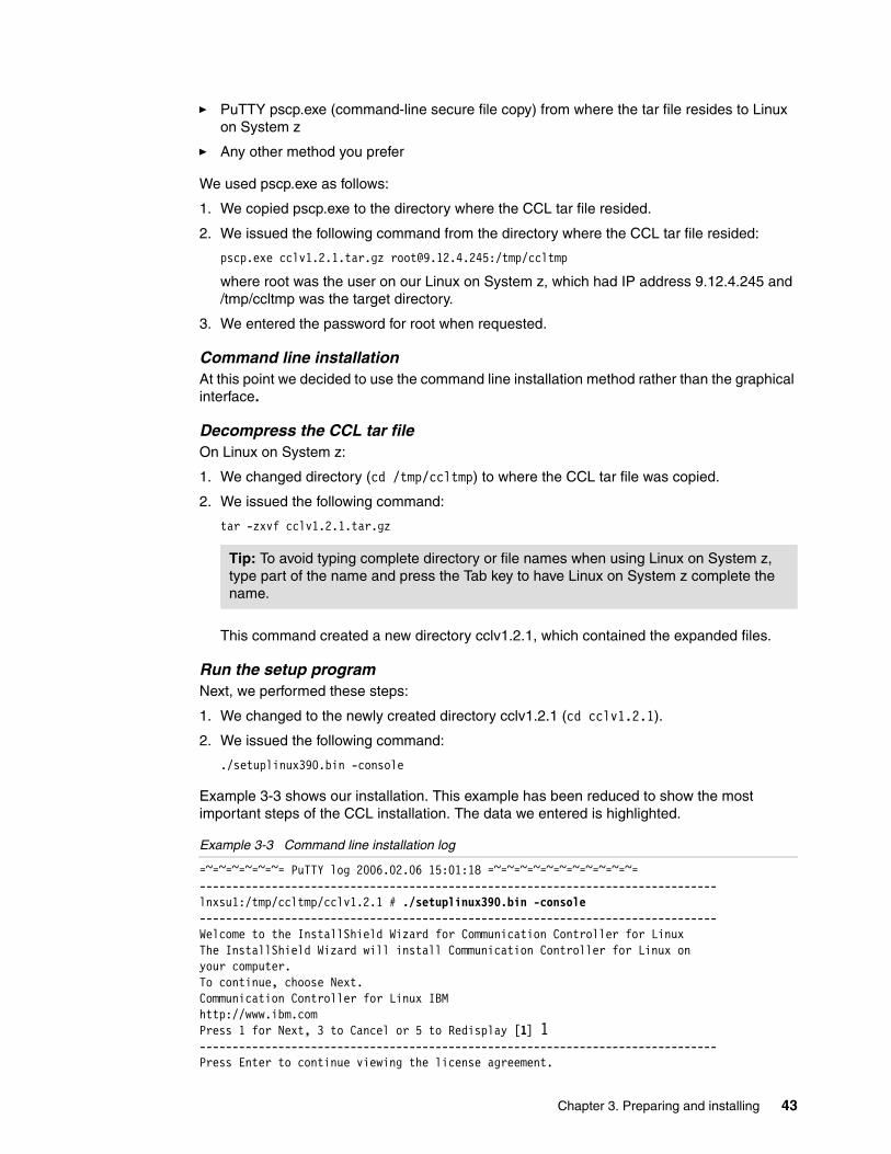
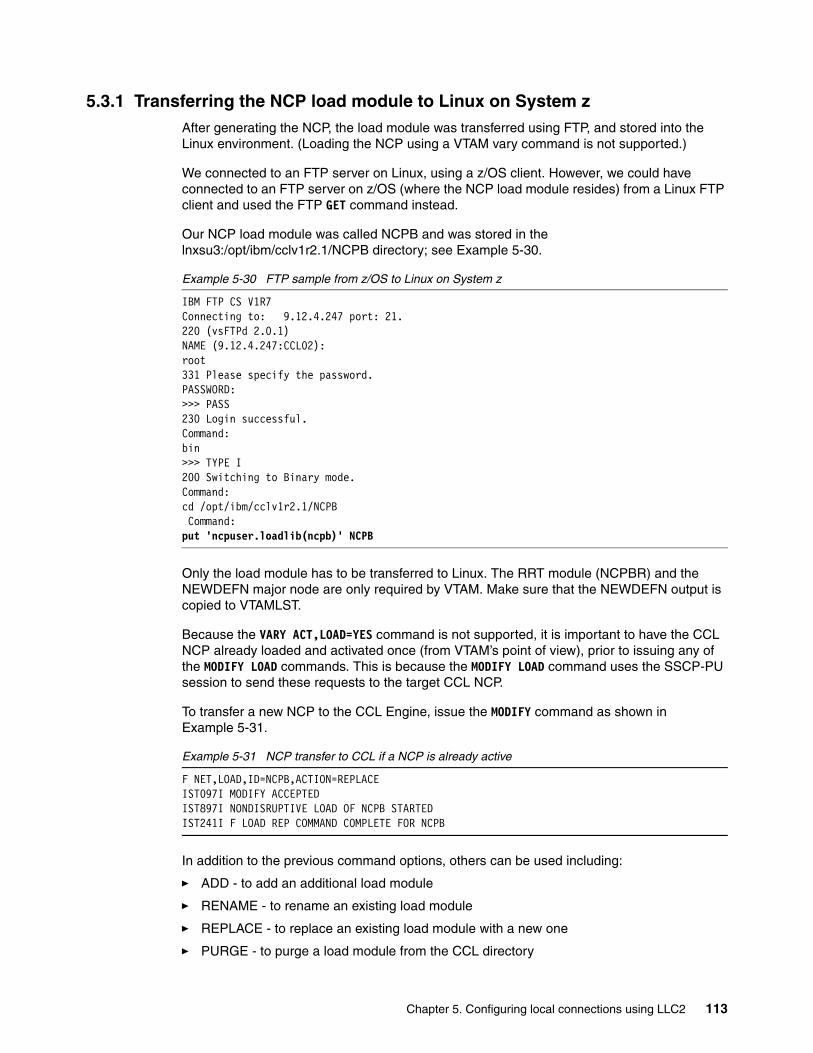
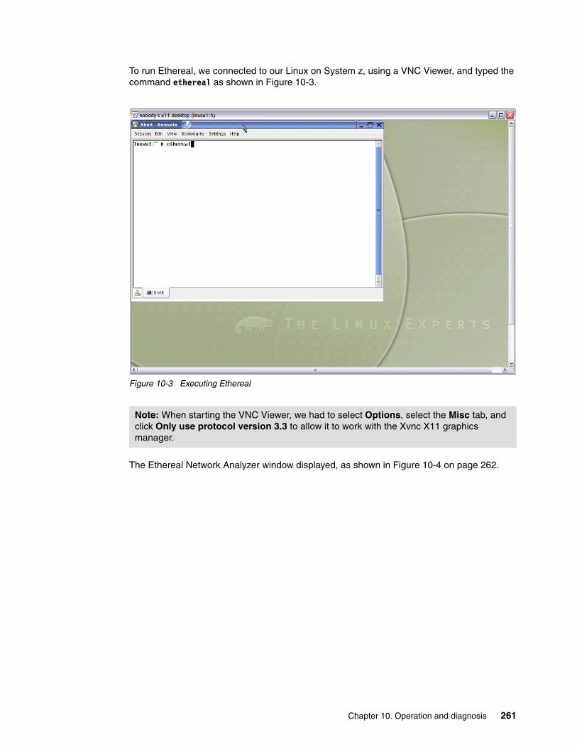
3.1 Installation overviewThe CCL product is shipped on a CD-ROM that contains the tar file (containing compressed code), the README file, and the document Communication Controller for Linux on System z Implementation and User’s Guide, SC31-6872.
Before installing CCL, the hardware and software prerequisites must be satisfied. Depending on the functions you wish to implement, additional actions may be required, such as installing new hardware or upgrading software and microcode levels.
This chapter also provides step-by-step instructions and guidance for the installation of CCL V1.2.1.
3.2 Hardware and software prerequisitesThis section will help ensure that you have the prerequisite hardware and software required by CCL.
3.2.1 Hardware requirementsThe hardware requirements will depend on the connectivity options needed; lists are provided based on connectivity type.
If you plan to use OSA LCS connectivity:� CCL requires a 31-bit or 64-bit System z9, zSeries, or S/390 G5/G6 server
� OSA-2, OSA-Express2, or OSA-Express features in either LSA or LCS mode (require copper wire features).
The supported OSA features are listed in Table 3-1.
Table 3-1 OSA features for LSA and LCS mode
When network connectivity for CCL NCPs is provided by the Open Systems Adapter (OSA) hardware running in LAN Channel Station (LCS) mode, the underlying network connectivity can be either Token Ring or Ethernet LAN connectivity. (When Ethernet connectivity is used, the NDH transparently maps between Ethernet frames and Token Ring frames. This way, all packets received by CCL NCPs appear as native Token Ring frames.)
Server type
Feature code
Ethernet Feature Code
Token Ring
G5/G6 2340 OSA-Express Fast Ethernet 5201 OSA2 ENTR
z800z900
2366 OSA-Express Fast Ethernet 2367 OSA-Express
z890z990
1366 OSA-Express (upgraded) 1000BaseT
2367 2367 OSA-Express
z9 BCz9 EC
3366 OSA-Express2 1000BASE-T Ethernet
(N/A) (N/A)
Note: The OSA-Express microcode must be at level 3.50 for z900 and z800. It must be at level 5.50 for z990 and z890.
32 CCL V1.2.1 Implementation Guide
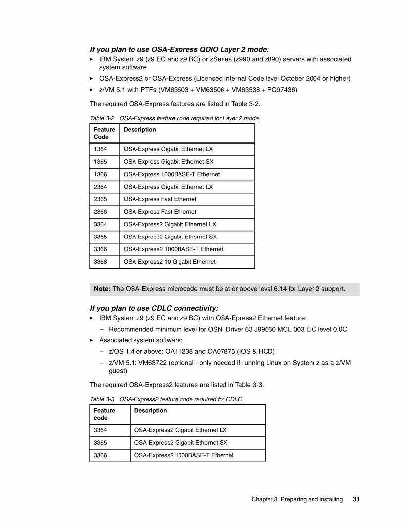
If you plan to use OSA-Express QDIO Layer 2 mode:� IBM System z9 (z9 EC and z9 BC) or zSeries (z990 and z890) servers with associated
system software
� OSA-Express2 or OSA-Express (Licensed Internal Code level October 2004 or higher)
– z/OS 1.4 or above: OA11238 and OA07875 (IOS & HCD)
– z/VM 5.1: VM63722 (optional - only needed if running Linux on System z as a z/VM guest)
The required OSA-Express2 features are listed in Table 3-3.
Table 3-3 OSA-Express2 feature code required for CDLC
Feature Code
Description
1364 OSA-Express Gigabit Ethernet LX
1365 OSA-Express Gigabit Ethernet SX
1366 OSA-Express 1000BASE-T Ethernet
2364 OSA-Express Gigabit Ethernet LX
2365 OSA-Express Fast Ethernet
2366 OSA-Express Fast Ethernet
3364 OSA-Express2 Gigabit Ethernet LX
3365 OSA-Express2 Gigabit Ethernet SX
3366 OSA-Express2 1000BASE-T Ethernet
3368 OSA-Express2 10 Gigabit Ethernet
Note: The OSA-Express microcode must be at or above level 6.14 for Layer 2 support.
Feature code
Description
3364 OSA-Express2 Gigabit Ethernet LX
3365 OSA-Express2 Gigabit Ethernet SX
3366 OSA-Express2 1000BASE-T Ethernet
Chapter 3. Preparing and installing 33
3.2.2 Software requirementsPart of the software requirements are the packages required by the level of Linux on System z that is being used.
� Instructions for installing these packages for Red Hat can be found in E.1.5, “Installing the additional packages required by CCL” on page 313.
� Instructions for installing these packages for SUSE can be found in D.1.6, “Installing additional packages required by CCL installation” on page 303.
This version of CCL has been tested with the following Linux on System z operating system versions.
� SUSE Linux Enterprise Server 8 for IBM Mainframe (SLES8)
� SUSE Linux Enterprise Server 9 for IBM Mainframe (SLES9)
� Red Hat Enterprise Linux AS 4 for IBM Mainframe (RHEL4)
CCL connections via CDLC (OSN) and QDIO Layer 2 is only supported with kernel 2.6-based Linux on System z distributions.
IBM is working with its Linux on System z distribution partners to ensure that the functions needed to exploit all of the Communication Controller for Linux features will be provided in future distribution releases or service updates.
For each Linux on System z distribution, a minimum set of rpm packages are required. These are shown in Table 3-4 on page 35 and Table 3-5 on page 36.
Note that the rpm requirements include the Linux on System z kernel source package. The Linux on System z kernel on the machine upon which the NDH module is built may require that the kernel source be installed to build kernel modules. The distribution documentation should detail if it requires the kernel source be installed to support and build external modules. However, to avoid any doubt, we show the steps required to prepare the kernel source.
To determine if you are running on a 31-bit or 64-bit machine, use the command uname -m. The output from this command will be one of the following:
� s390 - indicates you are running in 31-bit� s390x - indicates you are running in 64-bit
Minimum requirements
Note: Memory and DASD requirements for CCL are described in Communication Controller for Linux on System z Implementation and User’s Guide, SC31-6872.
Note: For the 64-bit distributions, some 31-bit ('s390') packages are needed in addition to the 64-bit ('s390x') packages. Apply the package shipped with your kernel version.
Important: Before attempting to download or apply the packages listed, use the rpm -qa command to determine if the package is already applied.
Example: rpm -qa | grep binutils
34 CCL V1.2.1 Implementation Guide
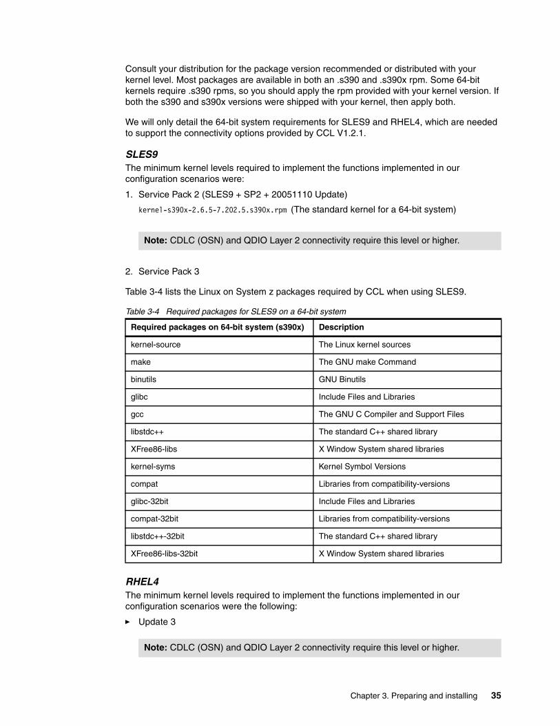
Consult your distribution for the package version recommended or distributed with your kernel level. Most packages are available in both an .s390 and .s390x rpm. Some 64-bit kernels require .s390 rpms, so you should apply the rpm provided with your kernel version. If both the s390 and s390x versions were shipped with your kernel, then apply both.
We will only detail the 64-bit system requirements for SLES9 and RHEL4, which are needed to support the connectivity options provided by CCL V1.2.1.
SLES9The minimum kernel levels required to implement the functions implemented in our configuration scenarios were:
1. Service Pack 2 (SLES9 + SP2 + 20051110 Update)
kernel-s390x-2.6.5-7.202.5.s390x.rpm (The standard kernel for a 64-bit system)
2. Service Pack 3
Table 3-4 lists the Linux on System z packages required by CCL when using SLES9.
Table 3-4 Required packages for SLES9 on a 64-bit system
RHEL4The minimum kernel levels required to implement the functions implemented in our configuration scenarios were the following:
� Update 3
Note: CDLC (OSN) and QDIO Layer 2 connectivity require this level or higher.
Required packages on 64-bit system (s390x) Description
kernel-source The Linux kernel sources
make The GNU make Command
binutils GNU Binutils
glibc Include Files and Libraries
gcc The GNU C Compiler and Support Files
libstdc++ The standard C++ shared library
XFree86-libs X Window System shared libraries
kernel-syms Kernel Symbol Versions
compat Libraries from compatibility-versions
glibc-32bit Include Files and Libraries
compat-32bit Libraries from compatibility-versions
libstdc++-32bit The standard C++ shared library
XFree86-libs-32bit X Window System shared libraries
Note: CDLC (OSN) and QDIO Layer 2 connectivity require this level or higher.
Chapter 3. Preparing and installing 35
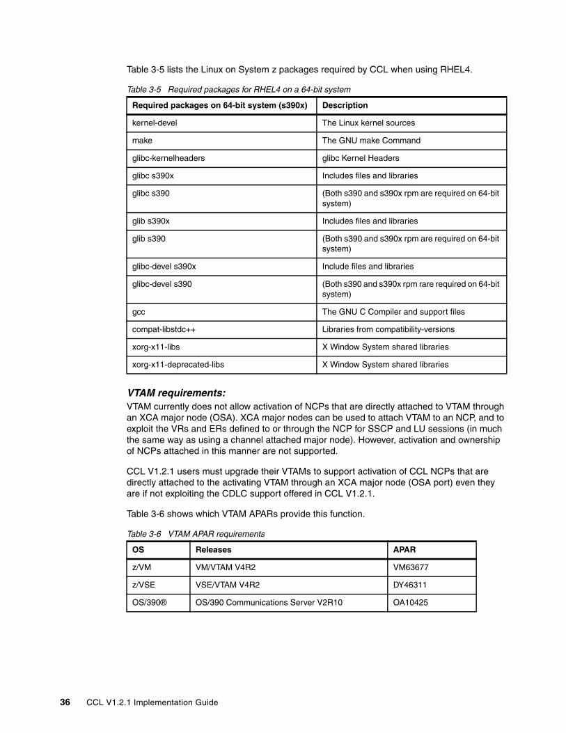
Table 3-5 lists the Linux on System z packages required by CCL when using RHEL4.
Table 3-5 Required packages for RHEL4 on a 64-bit system
VTAM requirements:VTAM currently does not allow activation of NCPs that are directly attached to VTAM through an XCA major node (OSA). XCA major nodes can be used to attach VTAM to an NCP, and to exploit the VRs and ERs defined to or through the NCP for SSCP and LU sessions (in much the same way as using a channel attached major node). However, activation and ownership of NCPs attached in this manner are not supported.
CCL V1.2.1 users must upgrade their VTAMs to support activation of CCL NCPs that are directly attached to the activating VTAM through an XCA major node (OSA port) even they are if not exploiting the CDLC support offered in CCL V1.2.1.
Table 3-6 shows which VTAM APARs provide this function.
Table 3-6 VTAM APAR requirements
Required packages on 64-bit system (s390x) Description
kernel-devel The Linux kernel sources
make The GNU make Command
glibc-kernelheaders glibc Kernel Headers
glibc s390x Includes files and libraries
glibc s390 (Both s390 and s390x rpm are required on 64-bit system)
glib s390x Includes files and libraries
glib s390 (Both s390 and s390x rpm are required on 64-bit system)
glibc-devel s390x Include files and libraries
glibc-devel s390 (Both s390 and s390x rpm rare required on 64-bit system)
gcc The GNU C Compiler and support files
compat-libstdc++ Libraries from compatibility-versions
xorg-x11-libs X Window System shared libraries
xorg-x11-deprecated-libs X Window System shared libraries
OS Releases APAR
z/VM VM/VTAM V4R2 VM63677
z/VSE VSE/VTAM V4R2 DY46311
OS/390® OS/390 Communications Server V2R10 OA10425
36 CCL V1.2.1 Implementation Guide
3.3 CCL installationThis section provides step-by-step instructions and guidance for the installation of CCL V1.2.1 on Linux on System z for SUSE and Red Hat.
The installation of SLES9 is described in Appendix D, “SUSE Linux Enterprise Server 9 (SLES9) installation” on page 297.
The installation of RHEL4 is described in Appendix E, “Red Hat Enterprise Linux AS 4 (RHEL4) installation” on page 307.
3.3.1 CCL installation on Red Hat Linux on System z (RHEL4)The CCL installation process uses an InstallShield executable to install the CCL binaries onto the target system, and an rpm to install the NDH open source kernel files onto the target system. The InstallShield executable and the NDH rpm are packaged together in a compressed tar file. This tar file needs to be copied to a temporary directory on the machine where CCL will be installed. Once untar’d, the InstallShield executable can be run either via command line or via graphical interface.
The following section describes the installation process we used.
Copy the tar file to the Linux on System z machine where CCL will be installed
If Linux on System z has not been configured to support an FTP server, the tar file can be transferred by using one of these methods:
� FTP GET from Linux on System z to an FTP server where the tar file resides.
� PuTTY pscp.exe (command-line secure file copy) from where the tar file resides to Linux on System z.
� Any other method you prefer.
In our case, we used pscp.exe as follows:
1. We copied pscp.exe to the directory where the CCL tar file resided.
2. Then we issued the following command from the directory where the CCL tar file resided:
where root was the user on our Linux on System z, which had IP address 9.12.4.246 and /tmp/ccltmp was the target directory.
3. We entered the password for root when requested.
z/OS z/OS Communications Server V1R2 OA10425
z/OS Communications Server V1R4
z/OS Communications Server V1R5
z/OS Communications Server V1R6
z/OS Communications Server later than V1R6 Included in base
OS Releases APAR
Chapter 3. Preparing and installing 37
Graphical installationAt this point we decided to use the graphical installation method rather than the command line:
1. We started the Virtual Network Computing (VNC) server on Linux on System z by issuing the following command:
vncserver
2. We set the password for the VNC server when requested. We took note of the display number that followed the hostname and the colon (:) as the delimiter.
3. We started a VNC viewer and connected to Linux on System z using the display number and the same password we specified.
Decompress the CCL tar fileOn Linux on System z:
1. We changed directory (cd /tmp/ccltmp) to where the CCL tar file was copied.
2. We issued the following command:
tar -zxvf cclvr1.2.1.tar.gz
This command created a new directory cclv1.2.1 which contained the expanded files.
Run the setup programNext, we performed these steps:
1. We changed to the newly created directory cclv1.2.1 (cd cclv1.2.1).
2. Then we issued the following command:
./setuplinux390.bin
The graphical installation process ran in a new window within the VNC viewer. The new windows appeared as blank frames. We moved the frames to the desired part of the screen and pressed the left mouse button to display them.
The initial dialog screen that was displayed is shown in Figure 3-1 on page 39. The installation dialog process is self-explanatory and we progressed by pressing Next.
Tip: To avoid typing complete directory or file names when using Linux on System z, type part of the name and press the Tab key to have Linux on System z complete the name.
Note: The VNC installation process requires a Java™ Runtime Environment (JRE™) to be installed on the machine running the VNC viewer.
38 CCL V1.2.1 Implementation Guide
Figure 3-1 CCL installation dialog initial screen
The default install directory is /opt/ibm/Communication_Controller_for_Linux, which is too long to type each time it is required. We recommend you use a shorter name. We used /opt/ibm/cclv1r21 as shown in Figure 3-2.
Figure 3-2 Install directory screen
When prompted, we chose the typical install option as shown in Figure 3-3 on page 40.
Chapter 3. Preparing and installing 39
Figure 3-3 Installation option screen
A password is requested, which will be used for accessing the CCL MOSS console. Make a note of the value you choose. Our screen looked like Figure 3-4.
Figure 3-4 MOSS password screen
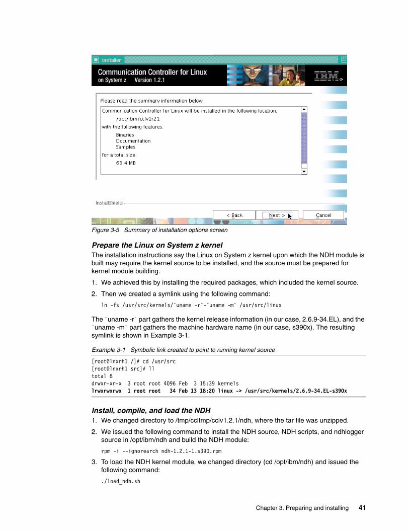
After all the options have been chosen, a summary dialog screen was displayed as shown in Figure 3-5 on page 41.
40 CCL V1.2.1 Implementation Guide
Figure 3-5 Summary of installation options screen
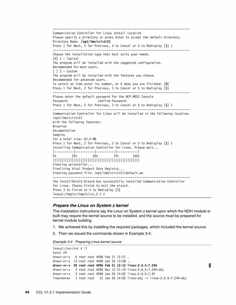
Prepare the Linux on System z kernelThe installation instructions say the Linux on System z kernel upon which the NDH module is built may require the kernel source to be installed, and the source must be prepared for kernel module building.
1. We achieved this by installing the required packages, which included the kernel source.
2. Then we created a symlink using the following command:
The ̀ uname -r` part gathers the kernel release information (in our case, 2.6.9-34.EL), and the `uname -m` part gathers the machine hardware name (in our case, s390x). The resulting symlink is shown in Example 3-1.
Example 3-1 Symbolic link created to point to running kernel source
[root@lnxrh1 /]# cd /usr/src[root@lnxrh1 src]# lltotal 8drwxr-xr-x 3 root root 4096 Feb 3 15:39 kernelslrwxrwxrwx 1 root root 34 Feb 13 18:20 linux -> /usr/src/kernels/2.6.9-34.EL-s390x
Install, compile, and load the NDH1. We changed directory to /tmp/ccltmp/cclv1.2.1/ndh, where the tar file was unzipped.
2. We issued the following command to install the NDH source, NDH scripts, and ndhlogger source in /opt/ibm/ndh and build the NDH module:
rpm -i --ignorearch ndh-1.2.1-1.s390.rpm
3. To load the NDH kernel module, we changed directory (cd /opt/ibm/ndh) and issued the following command:
./load_ndh.sh
Chapter 3. Preparing and installing 41
4. To confirm that the NDH had been loaded, we issued the command lsmod. The output is shown in Example 3-2.
Performing an unattended CCL installationAfter the first CCL install has been performed, future installs can use the silent install feature of the InstallShield, which enables you to perform an unattended installation. InstallShield silent install uses a response file to drive the InstallShield installation. A sample InstallShield response file is located in the samples subdirectory of the CCL install directory called samples/iss/ccl_silent.iss.
If you use the sample file, change the installation directory near the top of the response file and the NCP MOSS console password found at the bottom. Use the following command to run InstallShield with the silent install option:
3.3.2 CCL installation on SUSE Linux on System z (SLES9)The CCL installation process uses an InstallShield executable to install the CCL binaries onto the target system, and an rpm to install the NDH open source kernel files onto the target system. The InstallShield executable and the NDH rpm are packaged together in a compressed tar file. This tar file needs to be copied to a temporary directory on the machine where CCL will be installed. Once untar’d, the InstallShield executable can be run either via command line or via graphical interface.
The following section describes the installation process we used.
Copy the tar file to the Linux on System z machine where CCL will be installed
If Linux on System z has not been configured to support an FTP server, the tar file can be transferred by using either:
� FTP GET from Linux on System z to an FTP server where the tar file resides
42 CCL V1.2.1 Implementation Guide
� PuTTY pscp.exe (command-line secure file copy) from where the tar file resides to Linux on System z
� Any other method you prefer
We used pscp.exe as follows:
1. We copied pscp.exe to the directory where the CCL tar file resided.
2. We issued the following command from the directory where the CCL tar file resided:
where root was the user on our Linux on System z, which had IP address 9.12.4.245 and /tmp/ccltmp was the target directory.
3. We entered the password for root when requested.
Command line installationAt this point we decided to use the command line installation method rather than the graphical interface.
Decompress the CCL tar fileOn Linux on System z:
1. We changed directory (cd /tmp/ccltmp) to where the CCL tar file was copied.
2. We issued the following command:
tar -zxvf cclv1.2.1.tar.gz
This command created a new directory cclv1.2.1, which contained the expanded files.
Run the setup programNext, we performed these steps:
1. We changed to the newly created directory cclv1.2.1 (cd cclv1.2.1).
2. We issued the following command:
./setuplinux390.bin -console
Example 3-3 shows our installation. This example has been reduced to show the most important steps of the CCL installation. The data we entered is highlighted.
Example 3-3 Command line installation log
=~=~=~=~=~=~= PuTTY log 2006.02.06 15:01:18 =~=~=~=~=~=~=~=~=~=~=~=-------------------------------------------------------------------------------lnxsu1:/tmp/ccltmp/cclv1.2.1 # ./setuplinux390.bin -console-------------------------------------------------------------------------------Welcome to the InstallShield Wizard for Communication Controller for LinuxThe InstallShield Wizard will install Communication Controller for Linux onyour computer.To continue, choose Next.Communication Controller for Linux IBMhttp://www.ibm.comPress 1 for Next, 3 to Cancel or 5 to Redisplay [1] 1-------------------------------------------------------------------------------Press Enter to continue viewing the license agreement.
Tip: To avoid typing complete directory or file names when using Linux on System z, type part of the name and press the Tab key to have Linux on System z complete the name.
Chapter 3. Preparing and installing 43
-------------------------------------------------------------------------------Communication Controller for Linux Install LocationPlease specify a directory or press Enter to accept the default directory.Directory Name: /opt/ibm/cclv1r21Press 1 for Next, 2 for Previous, 3 to Cancel or 5 to Redisplay [1] 1-------------------------------------------------------------------------------Choose the installation type that best suits your needs.[X] 1 - TypicalThe program will be installed with the suggested configuration.Recommended for most users. [ ] 2 - CustomThe program will be installed with the features you choose.Recommended for advanced users.To select an item enter its number, or 0 when you are finished: [0] Press 1 for Next, 2 for Previous, 3 to Cancel or 5 to Redisplay [1]-------------------------------------------------------------------------------Please enter the default password for the NCP MOSS ConsolePassword: Confirm Password: Press 1 for Next, 2 for Previous, 3 to Cancel or 5 to Redisplay [1] 1-------------------------------------------------------------------------------Communication Controller for Linux will be installed in the following location:/opt/ibm/cclv1r21with the following features:BinariesDocumentation Samples for a total size: 63.4 MBPress 1 for Next, 2 for Previous, 3 to Cancel or 5 to Redisplay [1] 1Installing Communication Controller for Linux. Please wait...|-----------|-----------|-----------|------------|0% 25% 50% 75% 100%||||||||||||||||||||||||||||||||||||||||||||||||||Creating uninstaller...Finalizing Vital Product Data Registry...Creating password file: /opt/ibm/cclv1r21/default.pw-------------------------------------------------------------------------------The InstallShield Wizard has successfully installed Communication Controllerfor Linux. Choose Finish to exit the wizard.Press 3 to Finish or 5 to Redisplay [3] lnxsu1:/tmp/ccltmp/cclv1.2.1 #
Prepare the Linux on System z kernelThe installation instructions say the Linux on System z kernel upon which the NDH module is built may require the kernel source to be installed, and the source must be prepared for kernel module building.
1. We achieved this by installing the required packages, which included the kernel source.
2. Then we issued the commands shown in Example 3-4.
Example 3-4 Preparing Linux kernel source
lnxsu1:/usr/src # lltotal 24drwxr-xr-x 6 root root 4096 Feb 21 12:21 .drwxr-xr-x 13 root root 4096 Jan 26 13:58 ..drwxr-xr-x 20 root root 4096 Feb 21 12:15 linux-2.6.5-7.244 1drwxr-xr-x 3 root root 4096 Dec 12 21:19 linux-2.6.5-7.244-objdrwxr-xr-x 3 root root 4096 Jan 26 14:02 linux-2.6.5-7.97lrwxrwxrwx 1 root root 21 Jan 26 14:02 linux-obj -> linux-2.6.5-7.244-obj
44 CCL V1.2.1 Implementation Guide
drwxr-xr-x 7 root root 4096 Aug 10 2005 packageslnxsu1:/usr/src # cd linux-2.6.5-7.244lnxsu1:/usr/src/linux-2.6.5-7.244 # make cloneconfig 2lnxsu1:/usr/src/linux-2.6.5-7.244 # make modules_prepare 3lnxsu1:/usr/src/linux-2.6.5-7.244 # ln -s /lib/modules/`uname -r`/source /usr/src/linux 4lnxsu1:/usr/src/linux-2.6.5-7.244 # cd ..lnxsu1:/usr/src # lltotal 24drwxr-xr-x 6 root root 4096 Feb 21 12:23 .drwxr-xr-x 13 root root 4096 Jan 26 13:58 ..lrwxrwxrwx 1 root root 37 Feb 21 12:23 linux -> /lib/modules/2.6.5-7.244-s390x/source 5drwxr-xr-x 21 root root 4096 Feb 21 12:22 linux-2.6.5-7.244drwxr-xr-x 3 root root 4096 Dec 12 21:19 linux-2.6.5-7.244-objdrwxr-xr-x 3 root root 4096 Jan 26 14:02 linux-2.6.5-7.97lrwxrwxrwx 1 root root 21 Jan 26 14:02 linux-obj -> linux-2.6.5-7.244-objdrwxr-xr-x 7 root root 4096 Aug 10 2005 packages
Note the following explanations:
1 The Linux on System z kernel source directory with the highest level number, relating to the level of service pack, was used.
2 After changing directory to the location of the kernel source, the make cloneconfig command configured the kernel to match the running kernel.
3 This prepared the kernel for building external modules.
4 This created the symbolic link to the running kernel source. The `uname -r` part gathers the kernel release information (in our case, 2.6.5-7.244-s390x).
5 This is the resulting symlink that had been created.
Install, compile, and load the NDHNext, we performed these steps:
1. We changed directory to /tmp/ccltmp/cclv1.2.1/ndh, where the tar file was unzipped.
2. We issued the following command to install the NDH source, NDH scripts and ndhlogger source in /opt/ibm/ndh and build the NDH module:
rpm -i --ignorearch ndh-1.2.1-1.s390.rpm
3. To load the NDH kernel module, we changed directory:
cd /opt/ibm/ndh
4. We issued the following command:
./load_ndh.sh
5. To confirm that the NDH had been loaded we issued the command lsmod. The output is shown in Example 3-5 on page 46.
Performing an unattended CCL installationAfter the first CCL install has been performed, future installs can use the silent install feature of the InstallShield, which enables you to perform unattended installation. InstallShield silent install uses a response file to drive the InstallShield installation. A sample InstallShield response file is located in the samples subdirectory of the CCL install directory called samples/iss/ccl_silent.iss.
If you use the sample file, change the installation directory near the top of the response file, and the NCP MOSS console password found at the bottom. Use the following command to run InstallShield with the silent install option:
3.4 Preparing to run CCLPreparing to run CCL involves the following steps:
� Generating a CCL NCP load module � Creating a CCL Engine subdirectory on Linux on System z � Transferring your NCP load module to Linux on System z - optional with CDLC� Starting the CCL Engine
In the following sections, we describe these steps in more detail.
3.4.1 Generating a CCL NCP load moduleYou generate a CCL NCP the same way that you created a 3745 NCP—by using the NCP/EP Definition Facility (NDF) of the System Support Program (SSP). NDF processes your NCP definition statements to create the operational NCP load module and RRT deck. The configuration chapters of this book show the NCP source requirements for each type of connectivity scenario.
46 CCL V1.2.1 Implementation Guide
CCL emulates a 3745/46-31A with 16 MB of memory; however, an NCP from any 3745/46 model is supported. Even older model Communication Controllers (such as IBM 3705, 3720, ad 3725) should be considered when moving to CCL.
Note: When moving to CCL, check the MEMSIZE keyword value in the NCP source to ensure that it is set to 16 MB. Each CCL Engine instance requires 20 MB of memory, and that includes the 16 MB for NCP.
3.4.2 Creating a CCL Engine subdirectory on Linux on System zCCL NCP load modules must reside in a subdirectory of the CCL install directory (in our case, /opt/ibm/cclv1r21). The name of the subdirectory must be the same as the CCLEngineName used when starting the CCL Engine.
For example, if CCL was installed in the /opt/ibm/cclv1r21 directory, your CCLEngineName is CCL001, and your NCP load module name is NCP001, then the NCP001 load module must reside in the /opt/ibm/cclv1r21/CCL001 directory.
We decided to use a CCL Engine name that matched our NCP name, so in the configuration scenarios:
� We show an NCP called NCPA, which has a CCL Engine name of NCPA. Therefore, load module NCPA resided in a subdirectory called /opt/ibm/cclv1r21/NCPA.
� We show an NCP called NCPB, which has a CCL Engine name of NCPB. Therefore, load module NCPB resided in a subdirectory called /opt/ibm/cclv1r21/NCPB.
3.4.3 Transferring your NCP load module to Linux on System zAfter you have generated your CCL NCP, if you do not have a CDLC connection over which NCP can be loaded, you must transfer the load module to the Linux on System z image where CCL is installed. You can use File Transfer Protocol (FTP) to transfer your initial NCP load module. The name of your NCP load module is determined by the way you code the NEWNAME keyword on the CCL NCP’s BUILD statement.
In addition to creating an NCP load module, NDF also produces other load modules such as the resource resolution table (RRT) load module. The following list describes which files are needed by CCL, depending on which operating system was used to generate the CCL NCP.
� For an NCP generated on z/OS:
Transfer only the NCP load module. The NCP load module name is the name that you coded on the NEWNAME keyword on the BUILD definition statement.
� For an NCP generated on z/VM:
Transfer the entire CMS file that contains the NCP load module.
� For an NCP generated on z/VSE:
Transfer a sequential file that includes all of the NCP phases.
Rule: NCP load modules should always be saved in Linux on System z using the same name that was generated by the SSP product. Specifically, NCP load module names must be 7 characters or fewer, and all alphabetic characters must be upper case.
Otherwise, you will not be able to use the VTAM MODIFY LOAD command to rename or purge these NCP load modules, because VTAM always translates commands to upper case before processing.
Chapter 3. Preparing and installing 47
We decided to start an FTP server on our Linux on System z images to allow us to transfer NCP load modules, and other files, more easily. We used the Very Secure FTP Daemon (vsftpd) on both RHEL4 and SLES9. The daemon configuration is different for these two Linux on System z distributions, so we show both of them in the following sections.
VSFTPD on Red HatTo start an FTP Server on our Red Hat Linux on System z, we configured the vsftpd daemon using the following instructions:
1. A Red Hat typical installation does not include the vsftpd RPM package, so we needed to install it. We found the complete package name and directory location of the vsftpd RPM on the FTP Server we used to install RHEL4.
We copied it into a temporary directory on our RHEL4 Linux on System z and installed it with the following command:
rpm -ivh vsftpd-2.0.1-5.s390x.rpm
2. The vsftpd RPM command installs the program (/usr/sbin/vsftpd) and the related configuration files. We customized two files to be able to use the FTP daemon with our Linux on System z userid.
3. We removed the root userid from the /etc/vsftpd.user_list and /etc/vsftpd.ftpusers files that list the Linux on System z users not allowed to use FTP services.
4. We then started the daemon with the following command:
service vsftpd start
VSFTPD on SUSEThe default SUSE installation includes the vsftpd daemon, so we configured and started it as follows:
1. We started YaST on a VNC viewer session and from the main panel chose Security and Users Edit and create users. A new screen started, where we added a new user by selecting Add.
2. In the resulting panel we added a new userid ftpuser, as shown in Figure 3-6 on page 49.
48 CCL V1.2.1 Implementation Guide
Figure 3-6 YaST add user panel
3. We selected Details to enable FTP service for this user, as shown in Figure 3-7.
Figure 3-7 YaST add user details screen
Chapter 3. Preparing and installing 49
The YaST panel options on the lower right guided us to complete the user definition and quit YaST.
4. We modified the /etc/vsftpd.conf file by enabling the following statements:
write_enable=YESlocal_enable=YES
5. We started the vsftpd daemon using YaST. From the main panel we selected Network Services Network Services (inetd) Toggle Status ON for vsftpd, as shown in Figure 3-8.
Figure 3-8 YaST panel to start vsftpd daemon
Transferring the NCP load moduleNext, we followed these steps:
1. We created a subdirectory under the directory /opt/ibm/cclv1r21, which was the CCL install directory. We named this subdirectory NCPB, which became the CCL Engine name. (This happened to be the same as the CCL NCP instance name.)
2. We transferred our NCPB load module, using FTP in binary to this subdirectory.
Example 3-6 shows the directory tree in our environment after we transferred our NCP load module, NCPB.
Example 3-6 NCP load module location in the Linux on System z directory tree
[root@lnxrh1 ~]# cd /opt/ibm/cclv1r21/NCPB[root@lnxrh1 NCPB]# lltotal 5688
Note: You may need to modify file and directory permissions using the chmod command when not working in your home directory.
50 CCL V1.2.1 Implementation Guide
-rw-r--r-- 1 root root 2674792 Feb 7 11:19 NCPB
3.4.4 Starting the CCL EngineIf you have a CDLC connection over which an NCP can be loaded, you can start the CCL Engine with the CCL load/dump program (cclcldp), and then load the NCP directly over the CDLC connection. This method removes the requirement to first transfer an NCP load module to Linux on System z; details are shown in Chapter 4, “Configuring local connections using CDLC” on page 53.
If you do not have a CDLC connection over which NCP can be loaded, then after the CCL NCP load module has been transferred, you can start the CCL Engine and load the NCP; details are shown in Chapter 5, “Configuring local connections using LLC2” on page 91.
Configuring Linux on System z for first failure data capture If you specify the ulimit command (for example, ulimit -c unlimited) before you start the CCL Engine, Linux on System z will generate a core dump if the CCL Engine program terminates abnormally. The core dump file, core.nnnnn, is created in the CCL Engine installation directory, and may be quite large (50 M or more).
Chapter 3. Preparing and installing 51
52 CCL V1.2.1 Implementation Guide
Chapter 4. Configuring local connections using CDLC
In this chapter we provide step-by-step instructions and guidance for migrating IBM 3745 channel connections to CCL using an OSA-Express2 port with LPAR-to-LPAR communication. This support is an emulated Channel Data Link Control (CDLC) connection type.
The chapter covers the following topics:
� An overview of CDLC support
� Configuring CDLC connections
� Loading and contacting an NCP over a CDLC channel
4.1 An overview of CDLC supportCCL supports CDLC connections between the NCP and SNA hosts (for example VTAM or z/TPF) on System z9 (z9 EC and z9 BC) servers. This type of connection is shown in Figure 4-1.
Figure 4-1 CDLC connectivity on System z9
4.1.1 What is Channel Data Link Control (CDLC)Channel Data Link Control (CDLC) is the protocol used today by mainframe host operating systems to communicate with an NCP running in an IBM 3745 Communication Controller over ESCON channel hardware.
CCL running on a System z9 uses CDLC emulation to provide a more efficient connectivity alternative to SNA hosts running in the same System z9. No ESCON channel hardware is required; instead, an OSA-Express2 port is used.
4.1.2 How CDLC works with CCLTo the CCL NCP, the CDLC connections are the same as ESCON logical lines and stations. However, this support does not use actual ESCON hardware. Instead, an OSA-Express2 function called Open Systems Adapter for NCP (OSN) is used for CDLC communication.
OSN
CDLC (QETH)
CDLC
VTAM (z/OS, z/VSE, z/VM)z/TPF (CDLC only)
NCPNRFNPSI
Linux on System z (with CCL)
CDLC (QETH)
IPTG XOTSNA LLC2CDLCSNA LLC2
VTAM (z/OS, z/VSE, z/VM)z/TPF (CDLC only)
NCPNRFNPSI
Copper Copper Copper or fiber
Copper or fiber
SNA LLC2
SDLCF/R
X.25 QLLC
SNA LLC2 DLSW
X.25
XOT
IP Network
SDLCF/R
X.25 QLLC
X.25
SNA LLC2
DLSW XOT
SNA LLC2
IPTG
IP and SNA
LLC2
Linux on System z (with CCL)
DLSw
OSELSA OSN
OSELCS
OSDQDIO L2
OSDQDIO L3
54 CCL V1.2.1 Implementation Guide
The OSA-Express2 is configured to look like a CDLC-attached 3745 device to the SNA host systems on the System z9. The OSA microcode implements the CDLC protocol in the same way that a 3746 ESCON adapter does. Therefore, no changes are required to the SNA host software for this support. VTAM and z/TPF operate as they always have when connected to an NCP over a CDLC connection.
Figure 4-2 shows a comparison between using CDLC connections with 3745 hardware, and OSA-Express2 (OSN) hardware, when using CCL.
Figure 4-2 CDLC comparison between IBM 3745 and CCL
That same OSA-Express2 is also configured to function as a new device type, called OSN, to the Linux on System z images. OSN devices are very similar in definition and operation as QDIO devices for the Linux on System z systems. CCL emulates 3746 ESCON adapters to NCP, and communicates with the OSA-Express2 through this QDIO-like OSN device support. This enables the CCL NCP to control the OSA’s CDLC protocols, similar to the way that NCP controls the 3746 ESCON adapter’s CDLC protocols. The CCL NCP drives connection activation and deactivation, and processes all the SNA data that flows over the CDLC connection.
CDLC connections can be established only between SNA hosts and CCL NCPs in the same System z9 server, because there is no real channel hardware to carry the channel CCWs between the SNA host system and the OSA-Express2.
Both subarea PU type 5 (VTAM) and peripheral PU type 2.1 (VTAM or z/TPF) CDLC connections to SNA hosts are supported through an OSN CHPID type.
An OSN component overview is shown in Figure 4-3 on page 56.
Note: OSN functionality is provided only on the System z9 servers. SUSE Linux Enterprise Server 9 (with prerequisite service pack levels) and Red Hat Enterprise Linux AS 4 with Update 3 (base level) are the minimum levels required to support CCL CDLC connections.
System z9
Ethernet infrastructure
OSA-Express2 (OSN)
LPAR1 LPAR2
VTAM
CCL NCP
CDLC protocol CDLC protocol
QDIO protocol LPAR3
z/TPF
OSA-Express (OSD/OSE)
zSeries
3745
Token Ring infrastructure
CA-2CA-1
ESCONchannels
LPAR1 LPAR2
VTAM z/TPF
NCP
CDLC protocol CDLC protocol
Chapter 4. Configuring local connections using CDLC 55
Figure 4-3 OSN component overview
The OSA-Express2 can be shared across LPARs and even across Channel Subsystems (CSSs), so a single OSA-Express2 can support CCLs in multiple Linux on System z images, as well as multiple SNA host systems, concurrently. Each OSA-Express2 can support up to 180 CDLC connections between any CCL NCP and any SNA host system in the System z9 server.
An OSN CHPID supports up to 180 3745 device numbers (therefore supporting up to 180 CDLC connections to SNA hosts) and up to 480 OSN device numbers. The OSN device numbers are accessed from Linux on System z as QDIO device groups, with three devices used by each group; the first of them must have an even device address.
The Linux on System z QDIO device groups are linked to 3745 device numbers via a concept known as Channel Connection Identifiers (CCID), which is discussed in 4.2.4, “Defining ESCON resources in the NCP generation” on page 65.
The CCL NCP is activated from VTAM using the OSN CHPIDs 3745 device number as the CDLC link station. Loading and dumping of the CCL NCP directly over the OSN-based CDLC connection is supported, and using CCL load/dump program (cclcldp) support has the added benefit that an NCP load module does not need to be initially transferred to Linux on System z; instead, it can be loaded directly over the CDLC connection.
4.2 Configuring CDLC connectionsBefore you begin configuring CDLC connections, verify that the CDLC-related hardware prerequisites and software prerequisites have been satisfied, as described in Chapter 3, “Preparing and installing” on page 31.
Guideline: The OSA-Express2 card has two ports. When you configure one of the two ports for OSN, that physical port is disabled, because only LPAR-to-LPAR connectivity is used. You cannot share that port with OSD or OSE devices. However, you can define one of the two ports for OSN, and the other for OSD or OSE.
Figure 4-4 shows how to connect a CCL NCP to SNA hosts using CDLC connections. In this scenario, we used two VTAMs. However, the SNA host connected via the PU type 2.1 connection could equally well have been z/TPF.
The VTAM hosts (LPARs A23 with MIF ID 3 and A21 with MIF ID 1) and the Linux on System z guest (we tested using both LNXSU1 running SLES9, and LNXRH1 running RHEL4) are running on the same System z9. The OSN CHPID 0E, used for the CDLC connections, is part of Channel Subsystem ID 2 for LPARs A23 and A21.
Figure 4-4 Our CDLC connection topology
The steps we used to prepare our CDLC connections included:
� Defining an OSN CHPID with 3745 and OSN devices in the IOCP� Defining and activating the OSN devices to Linux on System z (SLES9)� Defining and activating the OSN devices to Linux on System z (RHEL4)� Defining ESCON resources in the NCP generation� Defining VTAM major nodes to contact the CCL NCP
In the following sections, we explain these steps in detail.
4.2.1 Defining an OSN CHPID with 3745 and OSN devices in the IOCPThe IOCP definition extracts related to CDLC we used are shown in Example 4-1 on page 58.
Note: In our example the OSN CHPID is shared by all three hosts, for simplicity. However, we recommend using multiple OSN CHPIDs for redundancy.
Linux on System z
CCLUSIBMSC.NCPA
SA=10
z/OS, z/VM, z/VSE or z/TPF
LPAR A21VTAMSA=76
USIBMSC.SC76M
OSN CHPID 0EPCHP 321
z/OS, z/VM, or z/VSE
LPAR A23VTAMSA=30
USIBMSC.SC30M
OSNDevice
Addresses2A48-2A4A
3745 Channel Address
2A40CSSID=2MIFID=3
PU Addr=01PU Type 5
3745 Channel Address
2A42CSSID=2MIFID=1
PU Addr=03PU Type 2.1
3745 Channel Address
2A41CSSID=2MIFID=1
PU Addr=02PU Type 5
Chapter 4. Configuring local connections using CDLC 57
Example 4-1 IOCP definition used for CDLC connectivity
* Define the LPARs that are in each CSS RESOURCE PARTITION=((CSS(0),(A0A,A),(A0B,B),(A0C,C),(A0D,D),(A* 0E,E),(A0F,F),(A01,1),(A02,2),(A03,3),(A04,4),(A05,5),(A* 06,6),(A07,7),(A08,8),(A09,9)),(CSS(1),(A1A,A),(A1B,B),(* A1C,C),(A1D,D),(A1E,E),(A1F,F),(A11,1),(A12,2),(A13,3),(* A14,4),(A15,5),(A16,6),(A17,7),(A18,8),(A19,9)),(CSS(2),* (A2A,A),(A2B,B),(A2C,C),(A2D,D),(A2E,E),(A2F,F),(A21,1),* 1 (A22,2),(A23,3),(A24,4),(A25,5),(A26,6),(A27,7),(A28,8),* 2 (A29,9))), * MAXDEV=((CSS(0),65280,0),(CSS(1),65280,0),(CSS(2),65280,* 65535))* * Define the CHPID (0E) and CUNUMBR for the physical OSA port (PCHID=321) * to all CSSs, as an OSN type of CHPID*CHPID PATH=(CSS(0,1,2),0E),SHARED, * PARTITION=((CSS(0),(A01,A02,A03,A04,A05),(=)),(CSS(1),(A* 11,A12,A13,A14,A15),(=)),(CSS(2),(A21,A22,A23,A24,A25),(* 3 =))),PCHID=321,TYPE=OSNCNTLUNIT CUNUMBR=2A40, * PATH=((CSS(0),0E),(CSS(1),0E),(CSS(2),0E)),UNIT=OSN** Define 3745 devices for the OSA. These map to VTAM definitions *IODEVICE ADDRESS=(2A40,008),UNITADD=01,CUNUMBR=(2A40),UNIT=3745 4** Define OSN devices for the OSA. These map to Linux on System z definitions *IODEVICE ADDRESS=(2A48,007),UNITADD=20,CUNUMBR=(2A40),UNIT=OSN 5*IODEVICE ADDRESS=2A4F,UNITADD=FE,CUNUMBR=(2A40),UNIT=OSAD 6
Note the following explanations for Example 4-1:
1 LPAR A21 had MIF ID 1.
2 LPAR A23 had MIF ID 3.
3 OSN CHPID was 0E and CSS ID 2 for LPARs A21 and A23.
4 These are the 3745 device addresses that VTAM used to communicate with the CCL NCP. The 008 defines the number of devices in the address range, starting with 2A40 (2A40-2A47). One 3745 device address is used for each CDLC connection.
5 These are the OSN device addresses that were defined and activated to Linux on System z. The defined range is 2A48 to 2A4E. Three sequential OSN device addresses are required for each QETH group device, and the first address in the range must be even, so 2 QETH group devices can be supported by this IODEVICE range; for example, osn0 = (2A48, 2A49, 2A4A) and osn1 = (2A4C, 2A4D, 2A4E).
Assuming the three required devices are allocated sequentially (even, odd, even), the next address (odd) is not used, and is wasted. Therefore, with 480 available OSN devices, 120 Linux on System z QDIO groups can be assigned (480 divided by 4).
Note: We coded UNITADD=01 because the valid ADDR parameter range for the NCP ESCON logical PU statement is x’01’-x’20’. If we had coded (or defaulted to) UNITADD=00 in the IOCP we would have been unable to use the first 3745 device address.
58 CCL V1.2.1 Implementation Guide
It is possible to avoid wasting the next odd device address by assigning it as part of a subsequent QDIO device group, for example:
osn0 - 2a48,2a49,2a4aosn1 - 2a4c,2a4d,2a4b
6 This is the OSAD device that was used to manage the OSA-Express from OSA/SF.
4.2.2 Defining and activating the OSN devices to Linux on System z (SLES9)This section describes the steps we used to define and activate the OSN devices when CCL ran under SLES9 SP2 + 20051110 Update.
1. We first dynamically defined the devices to Linux on System z so they could be used immediately.
We planned to use OSN device addresses 2A48 to 2A4A on our SLES9 Linux on System z guest LPAR LNXSU1. To make them available to LNXSU1, we attached them from z/VM using the following command from the MAINT userid:
ATTACH 2A48-2A4A LNXSU1
To make these devices permanently available following a z/VM restart, we issued the following commands from MAINT:
DIRM FOR LNXSU1 DEDICATE 2A48 2A48DIRM FOR LNXSU1 DEDICATE 2A49 2A49DIRM FOR LNXSU1 DEDICATE 2A4A 2A4A
2. Using a PuTTY connection, we logged on to LNXSU1 as root, and loaded the qeth device driver by issuing the following command:
modprobe qeth
3. We defined a qeth group device by writing the three OSN device numbers to /sys/bus/ccwgroup/drivers/qeth/group by issuing the following command:
As a result, the qeth device driver used the device bus-ID of the read device, the first address of the group. This process created a directory for a group device, called /sys/bus/ccwgroup/drivers/qeth/0.0.2a48.
The directory contains a number of attributes that determine the settings of the qeth group device. Unless otherwise specified, the attributes do not apply for an OSN CHPID type and you do not need to use them.
The contents of the /sys/bus/ccwgroup/drivers/qeth directory are shown in Example 4-2.
Example 4-2 Display of /sys/bus/ccwgroup/drivers/qeth directory
lnxsu1:/sys/bus/ccwgroup/drivers/qeth # lltotal 0drwxr-xr-x 2 root root 0 Jan 27 12:18 .drwxr-xr-x 3 root root 0 Jan 27 12:18 ..lrwxrwxrwx 1 root root 0 Feb 7 15:13 0.0.2a48 -> ../../../../devices/qeth/0.0.2a48lrwxrwxrwx 1 root root 0 Jan 27 12:18 0.0.c200 -> ../../../../devices/qeth/0.0.c200--w------- 1 root root 0 Feb 9 09:56 group--w------- 1 root root 4096 Jan 27 12:18 notifier_register
4. To activate the device group, we issued the following command, which sets the “online” attribute for our device group to 1:
Chapter 4. Configuring local connections using CDLC 59
Linux on System z assigns a device name and number to the OSN port, for example, osn0. The devices are created sequentially in the order that they are defined. This number is dynamically assigned. Using the command ifconfig -a you can display the defined devices (see Example 4-3).
Example 4-3 Display defined devices using ifconfig -a
6. To activate the osn0 device, we issued the ifconfig osn0 up command.
The ifconfig -a display for the osn0 device showed:
osn0 Link encap:Ethernet HWaddr 00:00:00:00:00:00 inet6 addr: fe80::/64 Scope:Link UP BROADCAST RUNNING NOARP MULTICAST MTU:1500 Metric:1 RX packets:0 errors:0 dropped:0 overruns:0 frame:0 TX packets:0 errors:0 dropped:0 overruns:0 carrier:0 collisions:0 txqueuelen:1000 RX bytes:0 (0.0 b) TX bytes:0 (0.0 b)
The OSN devices were then available for use in Linux on System z.
7. We statically defined the OSN devices to Linux on System z.
SLES9 provides mechanisms for statically predefining the OSN devices using hardware configuration files, so you can avoid manually entering these commands to bring the OSN online each time the system is started. We did this by creating a file in the /etc/sysconfig/hardware directory called hwcfg-qeth-bus-ccw-0.0.2a48. The file contents are shown in Example 4-5.
Example 4-5 hwcfg-qeth-bus-ccw-0.0.2a48
#!/bin/sh 1## hwcfg-qeth-bus-ccw-0.0.2a48## Hardware configuration for a qeth device at 0.0.2a48#
# Scripts to be called for the various events.SCRIPTUP='hwup-ccw'SCRIPTUP_ccw='hwup-ccw'SCRIPTUP_ccwgroup='hwup-qeth'SCRIPTDOWN='hwdown-ccw'
# CCW_CHAN_IDS sets the channel IDs for this device# The first ID will be used as the group IDCCW_CHAN_IDS='0.0.2a48 0.0.2a49 0.0.2a4a'
# CCW_CHAN_NUM set the number of channels for this device# Always 3 for an qeth deviceCCW_CHAN_NUM='3'
Note the following explanation for Example 4-5:
1 This line is required as this is a shell script.
8. We then created a file in the /etc/sysconfig/network directory called ifcfg-qeth-bus-ccw-0.0.2a48. The file contents are shown in Example 4-6.
Chapter 4. Configuring local connections using CDLC 61
Example 4-6 ifcfg-qeth-bus-ccw-0.0.2a48
# ifcfg-qeth-bus-ccw-0.0.2a48## Auto startup for a qeth device at 0.0.2a48#BOOTPROTO="static"UNIQUE=""STARTMODE="onboot"
In order for the new OSN device to be recognized at Linux startup, in some configurations you may have to modify the /etc/sysconfig/hardware/scripts/hwup-ccw file as follows:
Find Line: 1731/01|1731/05 Change to: 1731/01|1731/05|1731/06
We did not have to do this as the 1731/06 entry already existed in our SLES9 system configuration file.
4.2.3 Defining and activating the OSN devices to Linux on System z (RHEL4)This section describes the steps we used to define and activate the OSN devices when CCL ran under RHEL4 Update 3.
1. We first dynamically defined the devices to Linux on System z so they could be used immediately.
We planned to use OSN device addresses 2A48 to 2A4A on our RHEL4 Linux on System z guest LPAR LNXRH1. To make them available to LNXRH1, we attached them from z/VM using the following command from the MAINT userid:
ATTACH 2A48-2A4A LNXRH1
To make these devices permanently available following a z/VM restart, we issued the following commands from MAINT:
DIRM FOR LNXRH1 DEDICATE 2A48 2A48DIRM FOR LNXRH1 DEDICATE 2A49 2A49DIRM FOR LNXRH1 DEDICATE 2A4A 2A4A
2. Using a PuTTY connection, we logged on to LNXRH1 as root and loaded the qeth device driver by issuing the following command:
modprobe qeth
3. We defined a qeth group device by writing the three OSN device numbers to /sys/bus/ccwgroup/drivers/qeth/group by issuing the following command:
As a result, the qeth device driver used the device bus-ID of the read device, which is the first address of the group. This process created a directory for a group device called /sys/bus/ccwgroup/drivers/qeth/0.0.2a48.
The directory contains a number of attributes that determine the settings of the qeth group device. Unless otherwise specified, the attributes do not apply for an OSN CHPID type and you do not need to use them.
The contents of the /sys/bus/ccwgroup/drivers/qeth directory are shown in Example 4-7.
Example 4-7 Display of /sys/bus/ccwgroup/drivers/qeth directory
--w------- 1 root root 0 Oct 6 17:22 group--w------- 1 root root 4096 Oct 6 14:11 notifier_register
4. To activate the device group we issued the following command, which sets the “online” attribute for our device group to 1:
echo 1 > /sys/devices/qeth/0.0.2a48/online
Linux on System z assigns a device name and number to the OSN port, for example, osn0. The devices are created sequentially in the order that they are defined. This number is dynamically assigned. Using the command ifconfig -a you can display the defined devices (see Example 4-8).
Example 4-8 Display defined devices using ifconfig -a
6. To activate the osn0 device, we issued the ifconfig osn0 up command.
The ifconfig -a display for the osn0 device showed:
osn0 Link encap:Ethernet HWaddr 00:00:00:00:00:00 inet6 addr: fe80::/64 Scope:Link UP BROADCAST RUNNING NOARP MULTICAST MTU:1500 Metric:1 RX packets:0 errors:0 dropped:0 overruns:0 frame:0 TX packets:0 errors:0 dropped:0 overruns:0 carrier:0 collisions:0 txqueuelen:1000 RX bytes:0 (0.0 b) TX bytes:0 (0.0 b)
The OSN devices were then available for use in Linux on System z.
7. We statically defined the OSN devices to Linux on System z.
RHEL4 provides mechanisms for statically predefining the OSN devices, so you can avoid manually entering these commands to bring the OSN online each time the system is started. We did this by editing the file in the /etc directory called modprobe.conf to add the following statement:
alias osn0 qeth
The file contents are shown in Example 4-10.
Example 4-10 /etc/modprobe.conf
alias eth0 qethalias osn0 qethoptions dasd_mod dasd=201-202
8. We then created a file in the /etc/sysconfig/network-scripts directory called ifcfg-osn0. The file contents are shown in Example 4-11.
Example 4-11 ifcfg-osn0
# IBM QETHDEVICE=osn0BOOTPROTO=staticNETTYPE=qethONBOOT=yesSUBCHANNELS=0.0.2a48,0.0.2a49,0.0.2a4aTYPE=Ethernet
64 CCL V1.2.1 Implementation Guide
4.2.4 Defining ESCON resources in the NCP generationEach CDLC connection is defined to the CCL NCP as an ESCON logical PU. This means the NCP generation must have one ESCON logical PU definition for each CDLC connection to an SNA host, and it must also have all the supporting ESCON definitions that a logical PU requires (physical GROUP, LINE and PU, logical GROUP and LINE). However, there are no ESCON ports, no ESCON Directors, and no physical ESCON cabling systems of any kind. The parameters in the NCP generation that relate to those physical ESCON resources in a 3745 environment are meaningless in a CCL environment. Specifically, the physical LINE ADDRESS no longer identifies an ESCON port, and the logical LINE HOSTLINK no longer identifies a path through an ESCON Director.
What is required in the CCL environment is a way to identify, for each CDLC connection (each ESCON logical PU), the specific target 3745 device address that the OSA-Express2 should communicate with. Each specific 3745 device is uniquely identified by the combination of the following values:
� Channel Subsystem (CSS) ID� Multiple Image Facility (MIF) ID� Unit Address (the 3745 CDLC UA)
These three values are formatted into a four-byte field called the Channel Connection Identifier (CCID).
The CCID has a length of 4 bytes, with the format shown in Example 4-12.
Example 4-12 CCID format
Byte 0bits xx23 = Subchannel Set ID (SSID) - learned dynamicallybits 4567 = Use count
Byte 1bits 0123 = Channel SubSystem ID (CSS ID)bits 4567 = Multiple Image Facility (MIF) ID
Byte 2Reserved (Multiple CU)
Byte 33745 Unit Address
For example, the CCID for CSS_ID=2, MIF_ID=3, and UNITADD=01 would be 00230001. The CCID is used by CCL in flows to the OSN device, to identify the 3745 device that is the target. The CCID is present in all OSN assist primitives, as well as the QDIO header for data transfer. The CCID for CDLC connections can be seen in CCL Engine dumps, logs, and trace data. In addition you must identify, for each ESCON logical PU, which OSN device should be used to locate that specific 3745 device. During ESCON logical PU activation, CCL passes this information to the (correct) OSA-Express2, which establishes the CDLC connection.
There are two methods you can use to define the CCL CDLC parameters that are used to derive the CCID. The methods are NCP generation and CCLDEFS file, as explained here:
NCP generation With this method, you code parameters in the NCP generation by reusing the parameters that were previously described ESCON hardware components. This method is described in ““Mapping ESCON NCP definitions to the OSN device in the NCP gen” on page 66”. All or some of these parameters can be overridden with the CCLDEFS configuration file.
Chapter 4. Configuring local connections using CDLC 65
CCLDEFS file With this method, you code whatever values you want in the NCP generation, but override the NCP generation values with the real parameters, using a CCL-specific text definitions file (CCLDEFS). You must coordinate this file with the NCP definitions of the ESCON logical PU. This method is described in “Mapping ESCON NCP definitions to OSN device using the CCLDEFS file” on page 67.
Mapping ESCON NCP definitions to the OSN device in the NCP genIt is possible to correlate the NCP and OSN definitions automatically by using the correct naming and addressing convention in the NCP generation, as shown in Figure 4-5.
Figure 4-5 Correlating the definitions using the naming convention
The values required to build the CCID are derived from three existing NCP parameters (or overridden by a configuration file) to configure the OSN CDLC connectivity as follows:
1. The physical LINE statement identifies the target CSS ID. The same 16 constants are reused again, but now represent CSS IDs, and are still used in sequential order (for example, ADDRESS=2112 = CSS ID 0, ADDRESS=2176 = CSS ID 1, and so on). Following are the valid ESCON line numbers with the default CCS_ID of the line in the format of Line_Number(CSS_ID):
If the default CSS_ID is not correct for your configuration, you can use the CCLDEFS file to override the default value.
2. The logical LINE statement is reused to identify and configure the target MIF ID. The HOSTLINK parameter is reused to designate the MIF ID. The existing NCP generation
Note: If the naming and parameter guidelines cannot be met, mapping between NCP definitions and the information needed in the OSN context can be encoded in a CCLDEFS file. This is described in “Mapping ESCON NCP definitions to OSN device using the CCLDEFS file” on page 67.
LINE 2240
PU (Physical port)
LINE Hostlink=3
XXXX2A48 PU ADDR=01
LINE Hostlink=1
YYYY2A48 PU ADDR=02
.. .. (PU ADDR - up to 32 PUs) .. .. .. (LINE - up to 32 logical lines) .. .. .. (PU - up to 16 physical ports)
IODEVICE UNITADD=01 IODEVICE UNITADD=02
LPAR 3 LPAR 1
CSS 2
1 2 ... 16
LPAR 2
Linux
CCLCSS ID (2)
MIF ID ( 3)
UNITADD (01)
QDIO Devices 2A48-2A4A
01 02
NCP source
66 CCL V1.2.1 Implementation Guide
process will accept a value ranging 1 to 32. Following are valid HOSTLINK identifiers with the HOSTLINK default MIF ID in the format of HOSTLINK(MIF ID):
If the default MIF ID value is not correct for your configuration, you can use the CCLDEFS file to override the default value. In the System z9 environment, the highest supported value for MIF ID is x’F’, since the architecture allows up to 15 LPARs per Logical Channel Subsystem.
3. The PU statement is reused “as is”. The ADDR parameter continues to identify the specific 3745 UNIT ADDRESS. The valid range for ADDR is x’01’-x’20’.
CCL can have access to multiple OSN CHPIDs, in which case the specific OSN CHPID needs to be identified. In Linux on System z, this is accomplished by using the specific device name (for example, osn0).
In NCP, the OSN device number can be incorporated in the name used for the ESCON logical PU that represents the OSN channel connection. Set the last four characters of the logical PU name to the four hexadecimal digits representing the device address of the read qeth group device (the first one). For example, if the first OSN device number of the group is 0x2a48, you could name your ESCON logical PU CDLC2A48.
Mapping ESCON NCP definitions to OSN device using the CCLDEFS fileThere may be reasons why you cannot define the NCP ESCON definitions using the naming convention that allows correlation with the CCL CDLC parameters. For example, if you are starting with an existing NCP gen that already has the appropriate number of ESCON logical PU definitions, you might not want to change it. You might find it difficult to define the label of the logical PU statement in such a way that it meets local resource naming conventions and still allows the use of the last 4 characters of the PU name to represent the OSN’s read device address.
The CCL Engine has a text configuration file that you can use to override parameters for the CDLC logical stations, in case the configuration parameters in the NCP generation cannot be mapped to the appropriate OSN channel resources. This file must be named LOADMOD.ccldefs, and it must reside in the CCLEngineName directory.
The CDLCDEFS section of the text can contain a DEFAULT_DEVICE keyword, which you should use only if all the NCP’s CDLC connections go through the same OSN. A LOGICALPU statement should be coded for every ESCON logical PU statement in the NCP generation which needs to be overridden. The following keywords can be defined for each LOGICALPU:
PUNAME (Required) PUNAME is the label from the ESCON logical PU statement from the NCP gen.
DEVICE A 4-digit hexadecimal number in the range x’0000’ - x’FFFD’ that is the read subchannel device address of the OSN device. It is used to override the read subchannel device address that is encoded in the label from the ESCON logical PU statement.
Note: A HOSTLINK value greater than F will be flagged and will not work. It is flagged when the CCL tries to use the information to bring up the Channel link. You can use the CCLDEFS file to override the value if it is greater than x’F’.
Chapter 4. Configuring local connections using CDLC 67
CSS_ID A hexadecimal number in the range x’0’ - x’F’ that is used to override the CSS that is derived from the ADDRESS keyword of the physical LINE.
MIF_ID A hexadecimal number in the range x’0’ - x’F’ that is used to override the logical line’s HOSTLINK keyword.
UNITADD A 2-digit hexadecimal number in the range x’01’ - x’20’ that is used to override the logical PU’s UNITADD keyword.
Implementing naming convention mappingIn order to align our NCP definitions of ESCON resources with the CCL CDLC parameters that are needed to activate CDLC connections through OSN, we generated our ESCON resources in the CCL NCP according to the following strategy:
� Defined one ESCON physical GROUP
� Defined one ESCON physical LINE and PU for each CSS which contains an SNA host, setting ADDRESS to the value which corresponds to the CSS_ID for that CSS
� Defined one ESCON logical GROUP to map to each ESCON physical LINE
� Defined one ESCON logical LINE for each LPAR on that CSS that contains an SNA host to which a CDLC connection is needed, setting HOSTLINK to the value which corresponds to the MIF ID for that LPAR
� Defined one ESCON logical PU for each unique UNITADD to that MIF ID
This strategy allowed us to avoid using the CCLDEFS flat text configuration file for the CDLC connections.
The ESCON-related NCP source definitions used are shown in Example 4-13.
Example 4-13 NCP source definitions mapped to the OSN channel resources
********************************************************************** * CCL CDLC PHYSICAL LINE 2240 (CSSID:2) * ********************************************************************** * A10GRP GROUP LNCTL=CA,ANS=CONT * A10C2240 LINE ADDRESS=2240,ANS=CONT,SRT=(32765,32765), 1 XMONLNK=YES,SPEED=18000000 A10P2240 PU PUTYPE=1 * ********************************************************************** * CCL CDLC LOGICAL GROUP * ********************************************************************** A10CALG1 GROUP LNCTL=CA,PHYSRSC=A10P2240,MAXPU=32,NPACOLL=YES,ANS=CONT, TIMEOUT=180,DELAY=0.0,CASDL=10,SRT=(32765,32765) * ********************************************************************** * C1P12A48 PU ADDR = 01: CSS ID = 2: MIF = 3: to VTAM SC30M * ********************************************************************** * A10LL01 LINE ADDRESS=NONE,HOSTLINK=3,SPEED=18000000,MONLINK=YES, 2 NPACOLL=(YES,EXTENDED) C1P12A48 PU PUTYPE=5,ADDR=01,TRANSFR=140,TGN=1,MONLINK=YES,ANS=CONT 3 4
Note: On the BUILD statement, TYPGEN=NCP (rather than TYPGEN=NCP-R) is required. Also, the VERSION keyword must have the F extension for ODLC lines.
68 CCL V1.2.1 Implementation Guide
* ********************************************************************** * C2P12A48 PU ADDR = 02: CSS ID = 2: MIF = 1: to VTAM SC76M * * C2P22A48 PU ADDR = 03: CSS ID = 2: MIF = 1: to VTAM SC76M * ********************************************************************** * A10LL02 LINE ADDRESS=NONE,HOSTLINK=1,SPEED=18000000,MONLINK=YES, 5 NPACOLL=(YES,EXTENDED) C2P12A48 PU PUTYPE=5,ADDR=02,TRANSFR=140,TGN=1,MONLINK=YES,ANS=CONT 3 6C2P22A48 PU PUTYPE=2,ADDR=03,ANS=CONT 3 7
Note the following explanations for Example 4-13 on page 68:
1 Line address 2240 equates to CSS ID: 2.
2 Hostlink address 3 equates to MIF ID: 3.
3 Last four characters of the PU name equate to OSN device address 2A48.
4 PU ADDR 01 equates to UNITADD 01 of the 3745 device address in the IOCP.
5 Hostlink address 1 equates to MIF ID: 1.
6 PU ADDR 02 equates to UNITADD 02 of the 3745 device address in the IOCP.
7 PU ADDR 03 equates to UNITADD 03 of the 3745 device address in the IOCP.
Implementing CCLDEFS mappingFigure 4-6 shows an example where the NCP ESCON definitions could not be coded to allow automatic mapping to the appropriate OSN channel resources.
Figure 4-6 NCP definitions do not correlate to OSN channel resources
Note: When the NCP source contains an ESCON port (ESCP) line address, for example 2240, the entire range of line addresses up to the next available ESCP line address (2240-2303) are reserved, and cannot be used for Token Ring Port (TRP) addresses.
LINE 2112
PU (Physical port)
LINE Hostlink=1
XXXVTAM1 PU ADDR=01
YYYVTAM2 PU ADDR=02
.. .. (PU ADDR - up to 32 PUs) .. .. .. (LINE - up to 32 logical lines) .. .. .. (PU - up to 16 physical ports)
IODEVICE UNITADD=07 IODEVICE UNITADD=08
LPAR 5 LPAR 6
CSS 3
1 2 ... 16
LPAR 2
Linux
CCL
CSS ID (0)MIF ID (1)
UNITADD (01)
QDIO Devices 2A48-2A4A
07 08
NCP source
UNITADD (02)
Chapter 4. Configuring local connections using CDLC 69
The ESCON-related NCP source definitions used are shown in Example 4-14.
Example 4-14 NCP source definitions not mapped to the OSN channel resources
********************************************************************** * CCL CDLC PHYSICAL LINE 2112 * ********************************************************************** * A10CAPG GROUP LNCTL=CA,ANS=CONT * A10CAPL1 LINE ADDRESS=2112,ANS=CONT,SRT=(32765,32765), 1 XMONLNK=YES,SPEED=18000000 A10CAPP1 PU PUTYPE=1 ********************************************************************** * CDLC LOGICAL GROUP FOR all logicals over OSN=2A48 * ********************************************************************** A10CALG1 GROUP LNCTL=CA,PHYSRSC=A10CAPP1,MAXPU=32,NPACOLL=YES,ANS=CONT, TIMEOUT=180,DELAY=0.0,CASDL=10,SRT=(32765,32765) *A10CALL1 LINE ADDRESS=NONE,HOSTLINK=1,SPEED=18000000,MONLINK=YES, 2 NPACOLL=(YES,EXTENDED) ********************************************************************** * CONNECTION TO VTAM1 * ********************************************************************** A10VTAM1 PU PUTYPE=5,ADDR=01,TRANSFR=140,TGN=1,MONLINK=YES,ANS=CONT 3 4********************************************************************** * CONNECTION TO VTAM2 * ********************************************************************** A10VTAM2 PU PUTYPE=5,ADDR=02,TRANSFR=140,TGN=1,MONLINK=YES,ANS=CONT 3 4
Note the following explanations for Example 4-14 on page 70:
1 Line address 2112 equates to CSS ID: 0, which does not match the real CSS ID of 3.
2 Hostlink address 1 equates to MIF ID: 1, which does not map to the MIF IDs 6 and 7.
3 Last four characters of the PU names do not equate to OSN device address.
4 PU ADDRs do not equate to the UNITADDs of the 3745 devices address in the IOCP.
A CCLDEFS file was required to correlate the NCP definitions with the correct OSN channel resources for our CCLEngine called NCPA. The file, called /opt/ibm/cclv1r21/NCPA/NCPA.ccldefs, contained only CDLC definitions and is shown in Example 4-15.
The CDLC definitions in the ccldefs text file are re-parsed every time an ESCON logical PU is activated, so changes to the text file definitions take effect dynamically, without regenerating or reloading the CCL NCP. It is also possible to manually run this parsing function using the supplied parse_ccldefs utility. We ran this for our NCPname NCPA, as shown in Example 4-16.
Example 4-16 parse_ccldefs function
lnxsu1:/opt/ibm/cclv1r21 # ./parse_ccldefs NCPA/NCPAParsing definitions file 'NCPA/NCPA.ccldefs', output will be in 'NCPA/NCPA.ccldefs.PARSED'
------CCL Mapping Table-----CCLDEFS
------IP Mapping Table-----TCPDEFSENDTCPDEFS----end IP Mapping Table---
Note: The parse_ccldefs utility complains if there are no space characters at the end of each non-comment line in the ccldefs file. We had to manually edit the ccldefs file using the vi editor and insert a space character at the end of each non-comment line to avoid errors.
Chapter 4. Configuring local connections using CDLC 71
4.2.5 Defining VTAM major nodes to contact the CCL NCPVTAM SC30M loaded and activated the CCL NCP using the NCP generation process definitions.
VTAM SC76M contacted the CCL NCP over the CDLC channel, using both a subarea PU type 5 and a peripheral PU type 2.1 connection. The VTAM major nodes defined for the connections from SC76M were a channel attachment (CA) major node, shown in Example 4-17.
Example 4-17 Channel attachment major node for subarea connection to the NCP
CA76NCPA VBUILD TYPE=CA * CA76GRPA GROUP LNCTL=NCP ********************************************************************** C2P12A4C PU ADDR = 01: CSS ID = 2: MIF = 1: to VTAM SC76M *********************************************************************CA76LN1A LINE ADDRESS=2A41,MAXBFRU=36 CA76PU1A PU CHANCON=COND,MAXDATA=32768,TGN=1
The local SNA major node is shown in Example 4-18.
Example 4-18 Local SNA major node for peripheral connection to the NCP
LN76NCPA VBUILD TYPE=LOCAL * ********************************************************************* * C2P22A4C PU ADDR = 02: CSS ID = 2: MIF = 1: to VTAM SC76M ********************************************************************* * LN76PU1A PU PUTYPE=2,CUADDR=2A42,ISTATUS=ACTIVE,XID=YES, * VPACING=0,SSCPFM=USSSCS,MAXBFRU=255,DYNLU=YES, * CONNTYPE=APPN,CPCP=YES
4.3 Loading and contacting an NCP over a CDLC channelIn this section we describe:
� CDLC load/dump support� Configuring CDLC load/dump support� Loading the NCP from VTAM and verifying the CDLC connection� Contacting the NCP from VTAM and verifying the CDLC connection
72 CCL V1.2.1 Implementation Guide
4.3.1 CDLC load/dump supportIBM 3745 channel load/dump support is provided today for 3745 parallel channels and 3746 ESCON channels. Both require the 3745 controller load and dump program (CLDP) to be running in the 3745 CCU. The CLDP controls the adapters much like an NCP would, but its function is limited to loading and dumping the 3745 controller using the attached channel adapters.
The CCL load/dump function, cclcldp, does not require CLDP to be running in the CCU. Instead, the CCL includes load and dump logic that communicates directly with the NDH using AF_NDH sockets to perform the load and dump operations.
Loading an NCP into CCL over the CDLC channel can be performed in one of two ways:
1. The CCL can be loaded with an NCP.
If the CCL is loaded with an active NCP and a Write IPL command is received on the connection defined as the IPL port, the CCU and communication threads are terminated, and the CCL load/dump threads are started to continue the load/dump process.
2. The CCL can be running without an NCP.
To start a CCL without NCP, the CCL must be started using the following command:
./cclengine CCLEngineName -m cclcldp [-p xxxx where xxxx is the port address]
Note that -m cclcldp is a reserved load module name that indicates to the CCL that the engine is being started without an NCP, and the load/dump threads should be started to monitor for a Write IPL command. Because NCP load module names must be upper case, the lower case cclcldp is used to avoid a possible naming conflict with a real NCP CCLCLDP.
For a load operation, once the load is complete, the load/dump threads are terminated and the CCL engine is restarted with the newly loaded NCP.
For a dump operation, once the dump is complete, the CCL will be placed into a “Monitor for Write IPL” state, to await a reload of the NCP.
The CCL will also be placed into a “Monitor for Write IPL” state if the load or dump operation fails.
CCL CDLC load supports the following:
� Load the NCP, no save to disk� Load an NCP that is already on the disk, but the load/dump control byte indicates ‘no save
to disk’� Load the NCP from disk� Load the NCP, save to the disk
4.3.2 Configuring CDLC load/dump supportA configuration file, iplportdefs, is required to perform load and dump operations with CCL. There is one iplportdefs file per CCLEngineName, and the file identifies the one channel connection that can be used for CCL CDLC load and dump operations for that CCLEngineName.
Note: Loading an NCP with “no save to disk” still requires sufficient disk space to temporarily save the NCP load module being loaded. The load module will not be permanently saved to the disk. If enough disk space does not exist to save the temporary load module, the load operation will fail.
Chapter 4. Configuring local connections using CDLC 73
This configuration file enables cclcldp to associate the CDLC connection used for IPL with the QDIO devices and the corresponding definitions for the ESCON channel resource in your NCP generation.
The definitions for the QDIO devices consist of Multiple Image Facility (MIF) ID, Channel Subsystem (CSS ID), and the OSN device CHPID. The definitions for the NCP generation are ADDRESS for the physical link, HOSTLINK for the logical line, and ADDR for the PU.
The definitions coded in the configuration must match the definitions of the NCP being loaded into the CCL, or an NCP ABEND will result during NCP initialization.
IPLPORTDEFS statement guidelinesIPLPORTDEFS This is the starting delimiter for the IPL port definition
ADDRESS (Required) This is a 4-digit decimal number that defines the physical line address in the NCP that will be used for the IPL port. The valid values for ADDRESS are: 2112, 2176, 2240, 2304, 2268, 2432, 2496, 2560, 2624, 2688, 2752, 2816, 2880, 2944, 3008, and 3072.
HOSTLINK (Required) This is a decimal number that must be the same as the value coded on the HOSTLINK keyword of the corresponding logical LINE statement in your NCP gen. The valid range is 1 to 32.
ADDR (Required) This is a 2-digit hexadecimal number that must be the same as the value coded on the ADDR keyword of the corresponding PU statement in your NCP gen. The value coded must also be the same as the value specified for the IODEVICE UNITADD keyword in the host IOCDS definition. The valid range for ADDR is x’01’ to x’20’.
DEVICE (Required) This is a 4-digit hexadecimal number in the range x’0000’ to x’FFFD’. The DEVICE value is the OSN device number. It is the first of the 3-device range used for the OSN device in the Linux on System z image.
CSS_ID This is a hexadecimal number in the range x’0’ to x’F’. This value identifies the target Channel Subsystem ID. If you do not code the CSS_ID value, the default value is based on the ADDRESS keyword as follows: 2112 = CSS_ID 0, 2176 = CSS_ID 1, and so on.
MIF_ID This is a hexadecimal number in the range x’0’ to x’F’. This value identifies the target Multiple Image Facility ID. If you do not code the MIF_ID value, the default value is based on the HOSTLINK keyword as follows: HOSTLINK=1 MIF_ID=1, HOSTLINK=2 MIF_ID=2, and so on.
UNITADD This is a 2-digit hexadecimal number in the range x’01’ to x’20’. The value coded must be the same as the value specified for the IODEVICE UNITADD keyword in your host IOCDS definition. If you do not code the UNITADD value, the default is equal to the value coded on the ADDR keyword.
ENDIPLPORTDEFS This is the ending delimiter for the IPL Port definition.
The iplportdefs file changes become effective when you IPL the CCL engine, or when the CCL engine is restarted using the Linux on System z command. The configuration file is placed in the CCLEngineName directory, and has a file name of iplportdefs.
The iplportdefs file we used, /opt/ibm/cclv1r21/NCPA/iplportdefs, is shown in Example 4-19.
If the iplportdefs file does not exist in the CCLEngineName directory, the load of cclcldp will fail. The iplportdefs statements are automatically parsed when cclcldp is loaded into the CCL engine. It is also possible to manually run this parsing function using the supplied parse_iplportdefs utility, as shown in Example 4-20.
Example 4-20 parse_iplportdefs function
lnxsu1:/opt/ibm/cclv1r21 # ./parse_iplportdefs NCPA/iplportdefsFeb 13 10:40:11 CCZ8702I - Parsing of the IPL Port definitions file, 'NCPA/iplportdefs', is complete. The output will be in 'NCPA/iplportdefs.PARSED'0 Errors were encountered during parsing.
lnxsu1:/opt/ibm/cclv1r21 # cd NCPAlnxsu1:/opt/ibm/cclv1r21/NCPA # cat iplportdefs.PARSED0001:IPLPORTDEFS0002:*---------------------------------------------------------------------------------0003:* NCP Definition: ADDRESS=2240, HOSTLINK=3, ADDR=010004:* OSN Definition: CSS_ID=x'2' MIF_ID=x'3' UNITADD=x'01' CCID=x'00230001'0005:* DEVICE=x2A480006:*---------------------------------------------------------------------------------0007: ADDRESS 22400008: HOSTLINK 30009: ADDR 010010: DEVICE 2A480011: CSS_ID 20012: MIF_ID 30013: UNITADD 010014:ENDIPLPORTDEFSIPL Port: CCID(00230001) Device(2A48) TA(65) HOSTLINK(3) ADDR(1).Parsing complete, 0 errors, 0 warningsDefinition of a valid IPL Port was Successfullnxsu1:/opt/ibm/cclv1r21/NCPA #
Starting the CCL Engine with the CCL load/dump program (cclcldp)1. To start a CCL with the CCL load/dump program, we issued the following cclengine
command, suffixed with an ampersand (&) to run it in the background:
/opt/ibm/cclv1r21/logs/NCPA.cclcldp.log:[Feb 13 11:12:05]: NCPA 11374 INFO CCZ8702I - Parsing of the IPL Port definitions file, './NCPA/iplportdefs', is complete. The output will be in './NCPA/iplportdefs.PARSED'[Feb 13 11:12:05]: NCPA 11377 INFO CCZ6001I - HTTP Server Thread Started Thread ID: 1098546112 Process ID: 11374[Feb 13 11:12:05]: NCPA 11378 INFO CCZ2002I - Interval Timer Thread Started Thread ID: 1100790720 Process ID: 11374[Feb 13 11:12:05]: NCPA 11374 ERROR CCZ8704E - CDLC: Bind failed Resource temporarily unavailable[Feb 13 11:12:05]: NCPA 11374 ERROR CCZ0604E - Error trying to initialize the load/dump interface. Exit Emulator(42)
2. When we started CCL with cclcldp, we connected to the CCL MOSS console using a Web browser, targeting our Linux on System z IP address:port (9.12.4.245:4000). Then we entered the MOSS password and displayed the Disk IPL information, as shown in Figure 4-7.
Important: You should first ensure that the osn0 device is active by using the ifconfig -a command. If it is not, activate it using the ifconfig osn0 up command.
If the osn0 device is not up the cclengine command will fail, as shown by the messages seen in Example 4-21.
76 CCL V1.2.1 Implementation Guide
Figure 4-7 Initial Disk IPL information
4.3.3 Loading the NCP from VTAM and verifying the CDLC connection1. We issued the following VTAM command from SC30M to load the NCP over the CDLC
link station, saving the NCP load module to disk and turning the automatic dump/load switch on:
V NET,ACT,ID=NCPA,LOAD=YES,U=2A40,SAVEMOD=YES,DUMPLOAD=YES
The VTAM messages displayed are shown in Example 4-22.
Example 4-22 SC30M VTAM messages and display for CCL NCP load
IST097I VARY ACCEPTED IST461I ACTIVATE FOR U/RNAME ENTRY ID = 2A40-S STARTEDIST897I LOAD OF NCPA STARTED
D NET,ID=NCPA IST097I DISPLAY ACCEPTED IST075I NAME = NCPA, TYPE = PU T4/5 884 IST486I STATUS= PLOAD, DESIRED STATE= ACTIV IST247I LOAD/DUMP PROCEDURE STATUS = PLOAD IST1498I LOADING NCP FROM THE HOST IST1080I LOAD STATION NAME = 2A40-S IST1656I VTAMTOPO = REPORT, NODE REPORTED - YES IST484I SUBAREA = 10
Note: The U=2A40 operand can be omitted from the NCP load and activate commands if CUADDR=2A40 is coded on the NCP PCCU statement that defines the VTAM subarea for SC30M.
Chapter 4. Configuring local connections using CDLC 77
IST391I ADJ LINK STATION = 2A40-S, LINE = 2A40-L, NODE = SC30PUIST654I I/O TRACE = OFF, BUFFER TRACE = OFF IST1500I STATE TRACE = OFF IST314I END
IST270I LOAD OF NCPA COMPLETE - LOAD MODULE = NCPAIST464I LINK STATION 2A40-S HAS CONTACTED NCPA SA 10IST521I GBIND QUEUED FOR COS ISTVTCOS FROM SC30M TO NCPAIST528I VIRTUAL ROUTE NUMBER 0 1 IST523I REASON = NO ROUTES OPERATIVE IST093I NCPA ACTIVEIST093I A10P2240 ACTIVEIST464I LINK STATION C1P12A48 HAS CONTACTED SC30PU SA 30IST093I C1P12A48 ACTIVE 1
Note the following explanation for Example 4-22.
1 C1P12A48 is the Logical ESCON PU defined in the CCL NCP, which maps to 3745 device address 2A40 using CCID 00230001.
The MOSS Disk IPL information changed, as shown in Figure 4-8 on page 78.
Figure 4-8 Disk IPL information after the NCP was loaded
The MOSS CDLC Devices display, which showed PU C1P12A48 (the CDLC connection to VTAM SC30M) as active, was as shown in Figure 4-9.
78 CCL V1.2.1 Implementation Guide
Figure 4-9 MOSS CDLC devices display after NCP load and activation from SC30M
2. Following the successful load and activation of the NCP, we displayed the status of NCPA in VTAM on SC30M as shown in Example 4-23.
Example 4-23 NCPA display output
D NET,ID=NCPA IST097I DISPLAY ACCEPTED IST075I NAME = NCPA, TYPE = PU T4/5 245 IST486I STATUS= ACTIV, DESIRED STATE= ACTIV IST247I LOAD/DUMP PROCEDURE STATUS = RESET IST1656I VTAMTOPO = REPORT, NODE REPORTED - YES IST484I SUBAREA = 10 IST391I ADJ LINK STATION = 2A40-S, LINE = 2A40-L, NODE = SC30PUIST654I I/O TRACE = OFF, BUFFER TRACE = OFF IST1500I STATE TRACE = OFF IST077I SIO = 00170 CUA = 2A40 IST675I VR = 0, TP = 2 IST314I END
3. A display of the active Linux on System z processes (ps -ef) showed:
4.3.4 Contacting the NCP from VTAM and verifying the CDLC connection
Subarea PU Type 5 connection1. We issued the following VTAM command from SC76M to activate the Channel
Attachment (CA) major node, CA76NCPA. This allowed SC76M to contact the CCL NCP over the CDLC link station:
V NET,ACT,ID=CA76NCPA
Chapter 4. Configuring local connections using CDLC 79
The VTAM messages seen on SC76M and SC30M are shown in Example 4-24.
Example 4-24 VTAM messages when CA major node was activated
SC76M:IST093I CA76NCPA ACTIVE IEF196I IEF237I 2A41 ALLOCATED TO TP2A41 IST464I LINK STATION CA76PU1A HAS CONTACTED NCPA SA 10 IST093I CA76PU1A ACTIVE
SC30M:IST464I LINK STATION C2P12A48 HAS CONTACTED SC76M SA 76 IST093I C2P12A48 ACTIVE 1
Note the following explanation for Example 4-24:
1 C2P12A48 is the Logical ESCON PU defined in the CCL NCP, which maps to 3745 device address 2A41 using CCID 00210002.
The MOSS CDLC Devices display, indicating C2P12A48 was active, is shown in Figure 4-10 on page 80.
Figure 4-10 MOSS CDLC Devices display after CA major node activation on SC76M
Peripheral PU Type 2.1 connection
1. We issued the following VTAM command from SC76M to activate the Local SNA major node LN76NCPA. This allowed a peripheral (and APPN capable) connection to the CCL NCP over the CDLC link station:
V NET,ACT,ID=LN76NCPA
The VTAM messages seen on SC76M and SC30M are shown in Example 4-25.
80 CCL V1.2.1 Implementation Guide
Example 4-25 VTAM messages when local SNA major node was activated
SC76M:IST093I LN76NCPA ACTIVE IEF196I IEF237I 2A42 ALLOCATED TO TP2A42 IST1086I APPN CONNECTION FOR USIBMSC.SC30M IS ACTIVE - TGN = 21IST093I LN76PU1A ACTIVE IST1096I CP-CP SESSIONS WITH USIBMSC.SC30M ACTIVATED
SC30M:IST1086I APPN CONNECTION FOR USIBMSC.SC76M IS ACTIVE - TGN = 21IST093I C2P22A48 ACTIVE 1IST1096I CP-CP SESSIONS WITH USIBMSC.SC76M ACTIVATED
Note the following explanation for Example 4-25:
1 C2P22A48 is the Logical ESCON PU defined in the CCL NCP, which maps to 3745 device address 2A42 using CCID: 00210003.
The MOSS CDLC Devices display, indicating C2P22A48 was active, is shown in Figure 4-11 on page 81.
Figure 4-11 MOSS CDLC Devices display after Local SNA major node activation on SC76M
4.4 Diagnosing CCL CDLC problemsThe service aids that are available for diagnosing CCL CDLC problems are:
� CCL Engine logs, located in the /logs directory. (For more information on the available logs, refer to Chapter 10, “Operation and diagnosis” on page 239.)
� CDLC load/dump trace� CCL Engine dump
Chapter 4. Configuring local connections using CDLC 81
� GTF CCW trace– Taken as any other CCW trace
� NCP Line Trace– For information on NCP line traces refer to Chapter 10, “Operation and diagnosis” on
page 239� NCP Dump
– For information on NCP dumps refer to Chapter 10., CCL operation and diagnosis on page 153.
� NetView Alerts
4.4.1 CCL Engine logsUse the CCL log files (such as the CCL Engine log, system log, and BER log) to locate any messages related to CDLC connections.
For CDLC connections, the CCLEngineName.NCPname.log file (located in the logs subdirectory of the CCL install directory, /opt/ibm/cclv1r21/logs in our configuration) showed initialization and shutdown messages. The messages related to CDLC connections have a CDLC: label. These log messages can also be viewed from the CCL MOSS console.
The system log, /var/log/messages, also showed some messages related to CDLC connections. The messages related to CDLC connections have a CDLC: label. These log messages can also be viewed from the CCL MOSS console.
Example 4-26 shows an extract of the CCL Engine log messages when our NCP was loaded over the CDLC connection.
Example 4-26 CCL Engine log messages when NCP was loaded
[Feb 28 11:49:30]: NCPA 7253 DEBUG CCZ8013I - CDLC: Starting Transmit Thread for CCID: 0F230001[Feb 28 11:49:30]: NCPA 7258 DEBUG CCZ8003I - CDLC: NDHIO Transmit Packet Thread Started ID: 7258 Process ID: 7211[Feb 28 11:49:30]: NCPA 7253 DEBUG CCZ8014I - CDLC: Waiting For Transmit Thread Started for CCID: 0F230001[Feb 28 11:49:30]: NCPA 7253 DEBUG CCZ8015I - CDLC: Transmit Thread Started Signal Received for CCID: 0F230001[Feb 28 11:49:30]: NCPA 7253 DEBUG CCZ8016I - CDLC: Starting Receive Thread for CCID: 0F230001[Feb 28 11:49:30]: NCPA 7259 DEBUG CCZ8001I - CDLC: NDHIO Receive Packet Thread Started ID: 7259 Process ID: 7211[Feb 28 11:49:30]: NCPA 7253 DEBUG CCZ8017I - CDLC: Waiting For Receive Thread Started for CCID: 0F230001[Feb 28 11:49:30]: NCPA 7253 DEBUG CCZ8018I - CDLC: Receive Thread Started Signal Received for CCID: 0F230001[Feb 28 11:49:30]: NCPA 7253 DEBUG CCZ8019I - CDLC: Starting Receive Buffer Thread for CCID: 0F230001[Feb 28 11:49:30]: NCPA 7260 DEBUG CCZ8010I - CDLC: NDHIO Receive Buffer Handler Thread Started ID: 7260 Process ID: 7211[Feb 28 11:49:30]: NCPA 7253 DEBUG CCZ8020I - CDLC: Waiting For Receive Buffer Thread Started for CCID: 0F230001[Feb 28 11:49:30]: NCPA 7253 DEBUG CCZ8021I - CDLC: Receive Buffer Thread Started Signal Received for CCID 0F230001
Example 4-27 shows the CCL Engine log messages when our NCP was inactivated from VTAM.
82 CCL V1.2.1 Implementation Guide
Example 4-27 CCL Engine log messages when NCP was inactivated
For more information on the logs available, refer to Chapter 10, “Operation and diagnosis” on page 239.
4.4.2 CCL SIT traceTracing CCL CDLC connections can be performed using a CCL SIT trace.
� The CCL SIT for CDLC trace can be started either from VTAM, or from the CCL MOSS console
� The CCL SIT trace is written to a file (or files) in the /traces directory (CCLEngineName.ncpname.CCLSIT.trace), not to GTF. GTF does not need to be started.
� The CCL SIT is formatted with ccltap, not ACF/TAP.
We started a CCL SIT trace to capture both DPSA and CCL/NDH entries from the CCL MOSS console by choosing the BOTH button for the Network Device Handler CDLC trace, as shown in Figure 4-12.
Chapter 4. Configuring local connections using CDLC 83
Figure 4-12 Enabling CDLC SIT trace from the CCL MOSS
The trace data taken would have been exactly the same had we started the trace using MODIFY VTAM,TRACE,TYPE=SIT,ID=A10C2240 (our ESCON physical line name).
Example 4-28 shows an extract of the CCL SIT trace, formatted using ccltap, showing CDLC and DPSA entries.
Example 4-29 shows an extract of a CCL SIT trace, formatted using ccltap, taken using MODIFY VTAM,TRACE,TYPE=SIT,ID=A10LL01 (our ESCON logical line name for the CDLC connection to VTAM SC30).
Example 4-29 Formatted CDLC logical line SIT trace extract
4.4.4 CCL Engine dumpThe CCL Engine dump contains CDLC information. The CCL Engine internal trace for CDLC is activated from the CCL MOSS console, and written to internal storage that is viewed within a CCL Engine dump. Example 4-31 shows a CDLC-related internal trace and interface information from our configuration.
Example 4-31 CDLC information from formatted CCL Engine dump
Line Address: 2240 State: 3 LxbStat: 0000 LINEFLAGS: 40 ICB_Flags: C0 TA: 6500 TD: 8000 NPSA_LNVT Address: 0A02 LPSA_LNVT Address: 0A06 NCP_Buffer_Size: 248 LDPSA_Count: 10 Data_Treshhold: 00 NPSA_Status: 00 LPSA_Status: 00 Residual_Data_Count: 00 LPSA_Seq: EA58.... CCID: 04210003 OSN ID: 00002A48 Station_Name: C2P22A48 Pending LXBSTAT: 0000 Extended Status: 0000 Next Seq# Out: 0003 Last Seq# In: 004B OSN State: 0C OSN Resp Pend: 00 OSN No Resp Reqd: 00 OSN DE Pending: 02 Flush Primitives: 00 OSA Slowdown: 00 QDIO Slowdown: 00 Xmit In Progress: 00
88 CCL V1.2.1 Implementation Guide
Put Index: 02 Get Index: 02 OSNReqQH: 00000000 OSNReqQT: 00000000 OSNRspQH: 00000000 OSNRspQT: 00000000
For more information about using the CCL Engine dump, refer to Chapter 10, “Operation and diagnosis” on page 239.
For further details about CDLC support for CCL, refer to Communication Controller for Linux on System z9 and zSeries Implementation and User’s Guide, SC31-6872.
Chapter 4. Configuring local connections using CDLC 89
90 CCL V1.2.1 Implementation Guide
Chapter 5. Configuring local connections using LLC2
In this chapter we provide step-by-step instructions and guidance for migrating IBM 3745 channel or LAN connections to CCL, using OSA ports with Logical Link Control type 2 (LLC2) services. The types of connections we focus on are for VTAM-to-CCL NCP communication.
This chapter covers the following topics:
� An overview of LLC2 connectivity
� Configuring LLC2 local connections
� Activating and verifying the LLC2 connections to VTAM
5.1 An overview of LLC2 connectivityThe LLC2 connectivity between VTAM and CCL NCP that we discuss here is shown Figure 5-1. For all other connectivity using LLC2, refer to Chapter 6, “Configuring remote connections using LLC2” on page 123.
Figure 5-1 LLC2 connectivity scenario between VTAM and CCL NCP
5.1.1 What is the LLC2 connectivity supported by CCLLLC2 connectivity for CCL NCPs is provided by an OSA port. In a Linux on System z environment, the OSA port provides two options for transporting SNA traffic:
� LAN Channel Station (LCS) mode (OSA-Express CHPID type OSE)� QDIO Layer 2 (QETH) mode (OSA-Express CHPID type OSD)
The SNA LLC2 support provided with CCL allows you to migrate many of the lines and all of the Token Ring attached resources that were previously connected to the 3745. SNA LLC2 support allows CCL to exploit the OSA-Express port attachment to the LAN to send and receive SNA data. CCL sees the OSA port as if it were a Token Ring Interface Coupler (TIC). This maintains consistency with 3745 NCP architecture and definitions.
The underlying network connectivity can be either Token Ring or Ethernet LAN connectivity. When Ethernet connectivity is used, the NDH transparently maps between Ethernet frames
IPTG XOTSNA LLC2SNA LLC2
VTAM (z/OS, z/VSE, z/VM)z/TPF (CDLC only)
NCPNRFNPSI
Copper Copper Copper or fiber
Copper or fiber
SNA LLC2
SDLCF/R
X.25 QLLC
SNA LLC2 DLSW
X.25
XOT
IP Network
SDLCF/R
X.25 QLLC
X.25
SNA LLC2
DLSW XOT
SNA LLC2
IP-TG
IP and
SNA LLC2
Linux on System z (with CCL)
DLSw
SNA LLC2SNA LLC2
VTAM (z/OS, z/VSE, z/VM)
NCPNRFNPSI
Copper Copper Copper or fiber
Linux on System z (with CCL)
OSELSA
OSELCS
OSDQDIO L2
OSDQDIO L3
OSELSA
OSELCS
OSDQDIO L2
92 CCL V1.2.1 Implementation Guide
and Token Ring frames. In this way, all packets received by CCL NCPs appear as native Token Ring frames.
5.1.2 How the LLC2 connectivity worksLet’s discuss networking basics here. SNA LLC2 is part of the IEEE802.2 standard Logical Link Control (Type 2) networking, as shown in Figure 5-2.
SNA LLC2 is a connection-oriented Data Link Layer (DLC) protocol that handles flow control and retransmission at the link level.
A Media Access Control (MAC) address identifies an access point from a LAN perspective, and a Service Access Point (SAP) address is associated with a protocol (such as IP or SNA) at the Network Layer.
VTAM uses Link Service Architecture (LSA) support (OSA CHPID type OSE) to communicate at LLC2 level on a LAN, while Linux on System z uses its own device drivers to send and receive LAN frames over an OSA port (CHPID type OSE for LCS or CHPID type OSD for QDIO Layer 2).
Both MAC and SAP addresses have to be configured to establish a VTAM-to-CCL NCP connection when using LSA and LCS mode. When using Layer 2 for CCL, only the MAC address needs to be manually configured.
In order for an OSA port in LSA and LCS mode to be able to communicate at the LLC2 level, OSA/SF must be used to add the SNA support and the MAC and SAP addresses.
802.2 Logical Link Control Data
Link Layer(Layer 2)
Physical Layer(Layer 1)
Networking Layer(Layer 3)...
802.5Medium Access
Token-ring
802.5 Physical
LLC Type 1: connection-less DLC servicesLLC Type 2: connection-less and connection oriented DLC services
SAP 06
SAP 04
SAP C8
Networking Layer - such as IP
Networking Layer - such as SNA
802.3 Medium Access
Ethernet
802.3 Physical
10/100/1000BASE-T(RJ45 twisted pair)
1000BASE-LX/SX (Fiber optic cable)
Chapter 5. Configuring local connections using LLC2 93
For an OSA port in QDIO Layer 2 mode, OSA/SF is not needed. The MAC address is loaded to the port by way of Linux device configuration.
When attaching CCL NCPs to adjacent subarea VTAMs nodes, the adjacent VTAMs can be either owning hosts (VTAMs that activate the corresponding NCP major node) or data hosts (VTAMs that activate a subarea link to the CCL NCP, but do not activate the NCP major node itself). The subarea links defined to either type of VTAM node may be LAN-based, using an XCA major node. In order for an owning host VTAM to activate a CCL NCP over an XCA link, ALLOWACT=YES must be supported by VTAM, and coded on the XCA PU.
5.1.3 Overview of QDIO Layer 2 supportYou can use QDIO Layer 2 support on the CCL NCP side to establish an LLC2 connection to VTAM.
Each endpoint is identified by a Media Access Control (MAC) address, which in this case is a virtual MAC address that is assigned by the QDIO device driver in operating systems that support QDIO Layer 2 mode (which at the time of writing is Linux on System z as well as the z/VM virtual switch).
QDIO in Layer 2 mode handles traffic for any network protocol, such as NetBIOS, SNA, IPX™, IPv4, and IPv6. It is supported by CCL V1.2.1 when running on a Linux 2.6 kernel only.
Here are some of the advantages of using QDIO Layer 2 in conjunction with CCL:
� QDIO Layer 2 function allows CCL to support native SNA LLC2 traffic over a QDIO interface.
� The QDIO Layer 2 function simplifies the hardware configuration and the implementation design for the following reasons:
– It allows you to use fiber-optic Gigabit or 10 Gigabit network connectivity, thus giving you the option of using existing fiber optic cabling and switch infrastructure.
– There is no need to configure the Layer 2 OSA-Express port with OSA/SF to load an OAT table for Linux for System z.
– The MAC addresses you use in the CCL NCPs are virtual (handled by the QETH device driver in Linux for System z and by z/VM virtual SWITCH), so you can multiplex many SNA link stations over one physical network interface.
� A great scalability option is afforded, as you can have:
– Up to 2048 virtual MAC addresses.
– Up to 1920 QDIO device numbers (each QDIO device group of three device addresses represents an NCP LAN interface, all potentially using the standard SNA SAP 04 for boundary resources).
� QDIO Layer 2 can be implemented when Linux for System z is running in an LPAR or under z/VM (with or without the VSWITCH option). QDIO Layer 2 support requires minimum Linux on System z software levels of either SUSE SLES9 with an additional service pack, or Red Hat Enterprise Linux AS 4 (RHEL4) Update 3 at base level.
Note: Since QDIO Layer 2 mode allows for better sharing of the OSA port, we recommend using Layer 2 on System z9 and zSeries (z990 an z890) servers with OSA-Express and OSA-Express2 Ethernet features. All other server configurations must use LCS mode.
94 CCL V1.2.1 Implementation Guide
5.2 Configuring LLC2 local connectionsBefore you begin, verify that the LLC2 connection-related hardware and software prerequisites have been satisfied as described in Chapter 3, “Preparing and installing” on page 31.
Figure 5-3 shows connectivity between a CCL NCP (NCPB) and VTAM (SC76M) with the two supported connection types:
� LSA-to-Layer 2� LSA-to-LCS
Figure 5-3 LLC2 connectivity, VTAM LSA to CCL QDIO Layer 2 and LCS
The steps we used to prepare our LLC2 connections included:
� Defining an OSE CHPID for VTAM in the IOCP� Defining an OSD CHPID for Linux on System z in the IOCP� Defining an OSE CHPID for Linux on System z in the IOCP� Defining the QDIO Layer 2 devices to Linux on System z� Configuring the QDIO Layer 2 devices to Linux on System z� Configuring CCL’s OSE CHPID (MAC and SAP addresses) using OSA/SF� Defining the LCS devices to Linux on System z� Configuring the LCS network devices in Linux on System z� Configuring VTAM’s OSE CHPID (for SNA support) using OSA/SF� Defining the TIC resources in the NCP generation� Defining a VTAM XCA major node for LLC2 connections to CCL NCP
Note: You can use a fiber or copper OSA-Express Ethernet port for QDIO Layer 2 support. However, you still need a copper OSA port on the VTAM side for LSA support.
Notes:
� If you are implementing a VTAM-to-CCL NCP connection using Layer 2 mode, then you do not need to complete the OSE CHPID and LCS steps for the Linux on System z environment.
� Likewise, if you are using LCS mode, you do not need to complete the OSD CHPID and Layer 2 steps for the Linux on System z environment.
Linux on System z
CCLUSIBMSC.NCPB
SA=15
z/OS, z/VM, or z/VSE
LPAR A21VTAMSA=76
USIBMSC.SC76M
OSE Device Address:
228AMAC Address: 02004EC40080
SAP 28
OSE CHPID 0A
PCHP 1A1
OSD Device Addresses:2220-2222
MAC Address: 02004EC40020
SAP 04
OSD CHPID 07
PCHP 130
OSE Device Addresses:2260-2261
MAC Address: 02004EC40040
SAP 04
OSE CHPID 09
PCHP 221
TGN=1
TGN=2
LCS
LSA
Layer 2
Chapter 5. Configuring local connections using LLC2 95
5.2.1 Defining an OSE CHPID for VTAM in the IOCPThe IOCP definition extracts related to the OSA-Express OSE CHPID used by VTAM for LSA support are shown in Example 5-1.
Example 5-1 IOCP definitions used for VTAM OSE CHPID
1 These are the OSA device addresses that VTAM used to communicate with the CCL NCP. The 015 defines the number of devices in the address range, starting with 2280 (2280-228E). Only one OSA device address, 228A, was used for LLC2 communications. This device can be shared by multiple VTAMs using separate SAP addresses.
2 This is the OSAD device used by OSA/SF to communicate with the OSA-Express, for configuration and display purposes.
5.2.2 Defining an OSD CHPID for Linux on System z in the IOCPThe IOCP definition extracts related to the OSA-Express OSD CHPID used by Linux on System z for QDIO Layer 2 support are shown in Example 5-2.
Example 5-2 IOCP definitions used for CCL OSD CHPID
1 These are the OSA device addresses that CCL used to communicate with VTAM. The 015 defines the number of devices in the address range, starting with 2220 (2220-222E). Three device addresses are required for each QDIO device group, starting with an even device address.
5.2.3 Defining an OSE CHPID for Linux on System z in the IOCPThe IOCP definition extracts related to the OSA-Express OSE CHPID used by Linux on System z for LCS support are shown in Example 5-3.
Example 5-3 IOCP definitions used for CCL OSE CHPID
Note the following explanations for Example 5-3 on page 96:
1 These are the OSA device addresses that CCL used to communicate with VTAM. The 015 defines the number of devices in the address range, starting with 2260 (2260-226E). Two device addresses are required for each LCS device, a read and a write device.
2 This is the OSAD device used by OSA/SF to communicate with the OSA-Express, for configuration and display purposes.
5.2.4 Defining the QDIO Layer 2 devices to Linux on System zTo make the three QDIO Layer 2 addresses available to the Linux on System z guest, we issued the following command from an authorized z/VM user ID:
ATTACH 2220-2222 LNXSU3
To make the addresses permanently available to Linux on System z following an IPL, we issued the following commands from z/VM:
DIRM FOR LNXSU3 DEDICATE 2220 2220DIRM FOR LNXSU3 DEDICATE 2221 2221DIRM FOR LNXSU3 DEDICATE 2222 2222
In Linux on System z we used the lscss command to verify that the devices were available, as shown in Example 5-4.
Example 5-4 Logical channel subsystem display of QDIO devices
5.2.5 Configuring the QDIO Layer 2 devices to Linux on System z We configured the QDIO Layer 2 devices to Linux on System z using the YaST panels.
We started YaST2 on a VNC viewer screen. The same information can be seen from a PuTTY connection using YaST. In both cases, you need to navigate through YaST panels selecting the path Network Devices Network cards.
A YaST2 panel displayed which showed the device addresses available to Linux on System z; see Figure 5-4 on page 98.
Chapter 5. Configuring local connections using LLC2 97
We selected device address 2220 for QDIO Layer 2 support (it will automatically take three addresses in a row) and continued with Configure. There we enabled the Layer 2 support and defined the virtual MAC address needed for the network interface, as shown in Figure 5-5.
Figure 5-5 Enable Layer 2 support for QDIO devices
98 CCL V1.2.1 Implementation Guide
We defined the MAC address in canonical format here (its non-canonical form is 400072230004 and is the MAC address to be defined in the CCL NCP); see Figure 5-6.
Figure 5-6 IP configuration panel for QDIO Layer 2 device
We finished the definition, which writes the configuration file to create the network interface, and rebooted Linux on System z. Example 5-5 shows that the QDIO Layer 2 device eth0 has been defined and activated using the ifconfig command.
Example 5-5 ifconfig display of network interface eth0
The contents of file ifcfg-qeth-bus-ccw-0.0.2220 are shown in Example 5-6 on page 100.
Note: LCS and QDIO Layer 2 devices can be used for both IP and SNA traffic at the same time. Because we will use the QDIO Layer 2 device for SNA-only traffic, we chose the automatic address setup (via DHCP) option even though we did not have a DHCP server configured. The interface will be activated without an IP address, but will work at Layer 2.
Chapter 5. Configuring local connections using LLC2 99
5.2.6 Configuring CCL’s OSE CHPID (MAC and SAP addresses) using OSA/SFWe used OSA/SF to configure the OSE CHPID used by CCL to define a locally administered MAC address and SNA SAP addresses.
Because VTAM and CCL NCP cannot share the same OSA-Express port to communicate with each other, we needed to use two different CHPIDs for this LLC2 connection.
CHPID 09 used by Linux on System z running CCL will use the same device addresses configured by default for IP passthru in OSA-Express OAT ports, but we needed to add the SNA SAP addresses being supported by CCL on this OSA port. We also configured the locally administered MAC address for this OSA port to match the non-canonical MAC address required by CCL NCP.
If this interface will also be used for IP traffic, an IP address can also be coded. We did not do this.
For details on using OSA/SF, refer to OSA-Express Implementation Guide, SG24-5948.
Creating OSA configuration filesWe retrieved the existing configuration file from the OSA-Express port and modified it as required by defining the MAC address we wanted to use in CCL. Example 5-8 shows the OSA-Express configuration file we used for CHPID 09.
Example 5-8 OSA configuration file for CCL OSE CHPID
fenet.0.1 = IBM Default ConfigFile 1000Base /* Configuration name (32-char maxfenet.0.2 = /* User data (32-char max) fenet.0.3 = /* Port name (8-char max)
100 CCL V1.2.1 Implementation Guide
/* Data ignored for OSD CHPIDs fenet.0.4 = 02004EC40040 /* Local MAC address (12 hex digits) 1fenet.0.5 = Auto /* Speed/mode
Note the following explanation for Example 5-8 on page 100:
1 This is the canonical form of the MAC address 400072230002 being used by the CCL NCP TIC adapter.
Creating the OSA Address Table (OAT)We retrieved and updated the OAT as shown in Example 5-9 to define the SNA SAP addresses 04,08,0C and 10. In our scenario, only SAP04 was used by CCL.
Example 5-9 OAT used for CCL OSE CHPID
Image 1.2 (A12 ) 00(2260)* passthru 00 no 000.000.000.004 SIU ALL 000.000.000.008 000.000.000.012 000.000.000.016
Activating the OSA configurationOSA configuration changes are disruptive, therefore all active OSA devices must not have any active sessions. The OSAD device must be online to the host on which OSA/SF is running. Follow these steps:
1. Vary all OSA devices offline, except the OSAD device.
2. If the OSA-Express devices are already online to a Linux on System z image, it must be taken offline by issuing the following commands:
3. Log on to TSO from the system on which OSA/SF is running.
4. Execute the IOACMD Rexx command taken from the IOA.SIOASAMP library.
5. Select option 2 for loading the configuration, as shown in Example 5-10.
Example 5-10 IOACMD main menu
IOACMD: 1 - Clear Debug IOACMD: 2 - Configure OSA CHPID IOACMD: 3 - Convert OAT IOACMD: 4 - Get Configuration File IOACMD: 5 - Get Debug IOACMD: 6 - Get OSA Address Table IOACMD: 7 - Install IOACMD: 8 - Put OSA Address Table (OSA-2 only) IOACMD: 9 - Query IOACMD:10 - Set Parameter IOACMD:11 - Shutdown (VM only) IOACMD:12 - Start Managing IOACMD:13 - Stop Managing IOACMD:14 - Synchronize (OSA-2 only)
After option 2 is selected, the IOACMD configure list displays; see Example 5-11 on page 102.
Chapter 5. Configuring local connections using LLC2 101
Example 5-11 IOACMD configure list
IOACMD: Enter 'quit' to end IOACMD IOACMD: Enter 0 for help IOACMD: Enter 1 to configure an OSA-2 ATM CHPID IOACMD: Enter 2 to configure an OSA-2 FDDI, ENTR, fast Ethernet CHPIDIOACMD: Enter 3 to configure an OSA-Express gigabit Ethernet CHPID IOACMD: Enter 4 to configure an OSA-Express ATM CHPID IOACMD: Enter 5 to configure an OSA-Express fast Ethernet or an OSA-Express 1000Base-T Ethernet CHPID IOACMD: Enter 6 to configure an OSA-Express token ring CHPID IOACMD: Enter a blank line to get a list of valid OSA CHPIDs
6. We selected option 5 and were prompted as follows (our replies are shown in bold):
IOACMD: Enter CHPID -OR- 'quit' to end IOACMD
09 (this is the CCL OSE CHPID)
IOACMD: Is CHPID 09 of type OSD (QDIO)? (y/n) N (for OSE CHPID)
IOACMD: Enter the name of the OSA-Express port configuration file.
IOA.CHPID09.CONFIG
Then we were asked to enter the data set name containing the OAT file.
IOA.CHPID09.OAT
Enter option 1, activate with install, to complete the OSA-Express configuration.
Query host for CCL CHPID Next, we used OSA/SF to QUERY the OSE CHPID 09 to verify the configuration settings we had chosen. The output is shown in Example 5-12.
Example 5-12 Query for CCL CHPID
****************************************************** * Port information follows for OSA-Express2 CHPID 09 * ************************************************************************ * Information for OSA-Express2 CHPID 09 port 0 * * Settable port parameters (using SET_PARM) are preceded by 's-' * * Configurable port parameters (using CONFIG_OSA) are preceded by 'c-' * ************************************************************************ Port type ----------------------> 1000Base-T Ethernet c-Configuration name -------------> IBM Default ConfigFile 1000Base s-LAN traffic state --------------> Enabled Service mode -------------------> No Modes configured ---------------> Passthru SNA 1c-Local MAC address --------------> 02004EC40040 2 Universal MAC address ----------> 00096B1A7824 c-Configured speed/mode ----------> Auto negotiate Active speed/mode --------------> 1000 Mbps full duplex c-User data ----------------------> c-Port name ----------------------> Object ID ----------------------> 1.3.6.1.4.1.2.3.26 ************************************************************************ Image 1.2 (A12 ) 00(2260)* passthru 00 no 000.000.000.004 SIU ALL 3 000.000.000.008 000.000.000.012 000.000.000.016
102 CCL V1.2.1 Implementation Guide
Note the following explanations for Example 5-12 on page 102:
1 SNA support was added to this CHPID by coding an SNA device for other LPARs, even though SNA is not used by Linux on System z. Because the CHPID is shared, it can be used by a VTAM not communicating with our CCL, which requires this SNA support.
2 The canonical format of the CCL NCP TIC MAC address (400072230002) has been loaded correctly on the OSA-Express port.
3 The SAP addresses are correctly associated to the device address we need to use in Linux on System z (running in LPAR A12).
5.2.7 Defining the LCS devices to Linux on System zIn our environment we defined devices 2260 and 2261 to the Linux on System z guest of z/VM running in LPAR A12.
1. To make use of the I/O addresses, we attached them to the Linux guest using the following CP command from z/VM MAINT user ID:
ATTACH 2260-2261 LNXSU3
2. To make these definitions permanent in z/VM, we issued the following command:
DIRM FOR LNXSU3 DEDICATE 2260 2260DIRM FOR LNXSU3 DEDICATE 2261 2261
The command needs to be issued from an authorized z/VM user for all OSA device addresses. You may also change the z/VM user profile for Linux on System z to achieve this.
3. To list the available channel subsystem devices to Linux on System z, we issued the lscss command. The output showing our LCS devices is shown in Example 5-13.
Example 5-13 Logical channel subsystem display of the LCS devices
Device Subchan. DevType CU Type Use PIM PAM POM CHPIDs----------------------------------------------------------------------0.0.2260 0.0.0021 0000/00 3088/60 yes 80 80 FF 09000000 000000000.0.2261 0.0.0022 0000/00 3088/60 yes 80 80 FF 09000000 00000000
5.2.8 Configuring the LCS network devices in Linux on System zThe LCS device can be configured dynamically and statically in Linux on System z.
The dynamic option is useful for a quick start, but you lose the configuration when you reboot the system if you do not fix it using the static definition. In this section, we demonstrate both options (for Red Hat and SUSE distributions).
Dynamic device definitionWe followed these to dynamically create the LCS devices:
1. We logged on to LNXSU3 using PuTTY and issued the following command:
modprobe lcs
This command loads the LCS device driver into the kernel. To verify that the drivers were loaded, we issued the lsmod command; Example 5-14 on page 104 displays the output.
Chapter 5. Configuring local connections using LLC2 103
Example 5-14 lsmod output showing lcs device drivers
Static device definitionIt is important to create the configuration files to define the network interface statically, in order to avoid losing the LCS device after a reboot of Linux on System z.
The steps required for this task on Red Hat are different from the ones needed for SUSE. We show here details for both distributions.
Configuring an LCS interface in Red HatRed Hat only has one file to define the device parameters, and it must be located under the /etc/sysconfig/network-scripts directory. The file name must be in the ifcfg-eth1 format. We added an LCS interface for device addresses 2260 and 2261. The content of the file is shown in Example 5-17.
Example 5-17 LCS device definition on Red Hat Linux on System z
[root@lnxrh1 network-scripts]# cat ifcfg-eth1# IBM LCSDEVICE=eth1BOOTPROTO=staticBROADCAST=9.12.5.255IPADDR=9.12.4.250NETMASK=255.255.254.0NETTYPE=lcsNETWORK=9.12.4.0ONBOOT=yesSUBCHANNELS=0.0.2260,0.0.2261TYPE=EthernetPORTNAME=0
In order to activate the eth1 device at Linux on System z startup, you need to add an entry for it in the file called /etc/modprobe.conf, as shown in Example 5-18.
Configuring an LCS interface in SUSE In this section we show the required steps for the SUSE distribution. We added an LCS interface for device addresses 2260 and 2261.
SLES9 provides mechanisms for statically predefining the LCS devices using hardware configuration files, so you can avoid manually entering commands or using YaST to bring the devices online each time the system is started. We did this by creating, in the /etc/sysconfig/hardware directory, a file called hwcfg-lcs-bus-ccw-0.0.2260.
The content of the hardware characteristics of the device in file hwcfg-lcs-bus-ccw-0.0.2260 is shown in Example 5-20.
Example 5-20 /etc/sysconfig/hardware configuration file for lcs device on SUSE
Next, we created a file in the /etc/sysconfig/network directory called ifcfg-lcs-bus-ccw-0.0.2260. The content of the network configuration file ifcfg-lcs-bus-ccw-0.0.2260 for the LCS device on SUSE is shown in Example 5-21.
Example 5-21 /etc/sysconfig/network configuration file for lcs device on SUSE
These are text files, so you can either create these files “from scratch” or copy similar ones and modify them according to your needs.
5.2.9 Configuring VTAM’s OSE CHPID (for SNA support) using OSA/SFWe used OSA/SF to configure the OSE CHPID used by VTAM to add SNA support, and to define a locally administered MAC address. For details about using OSA/SF, refer to OSA-Express Implementation Guide, SG24-5948.
106 CCL V1.2.1 Implementation Guide
Updating the OSA configuration fileWe retrieved the existing configuration file from OSE CHPID 0A, and updated it with the MAC address to be used by VTAM and with the SNA parameters. Example 5-22 shows what we used.
Example 5-22 OSA configuration file for VTAM CHPID
fenet.0.1 = IBM Default ConfigFile 1000Base /* Configuration name (32-char max)fenet.0.2 = /* User data (32-char max) fenet.0.3 = /* Port name (8-char max) /* Data ignored for OSD CHPIDs fenet.0.4 = 02004EC40080 /* Local MAC address (12 hex digits) 1fenet.0.5 = Auto /* Speed/mode /* Auto - auto negotiate sna.0.1 = Configuration /* Configuration name (32-char max) sna.0.2 = 90.00 /* Inactivity timer (ti) /* .24-90 in increments of .12 /* 0 disables the inactivity timer sna.0.3 = 10.00 /* Response timer (t1) /* .20-51 in increments of .20 sna.0.4 = 1.04 /* Acknowledgement timer (t2) /* .08-20.4 in increments of .08 sna.0.5 = 4 /* N3 (1-4) sna.0.6 = 8 /* TW (1-16)
Note the following explanation for Example 5-22:
1 We specified the canonical form of MAC address 400072230001 to be used by VTAM. VTAM does not need to use locally administered addresses (we could have used the OSA-Express port hardware MAC address for VTAM), but we configured it like this so that it could also be used by a separate CCL NCP’s physical TIC definition, not related to this configuration.
In the event of a hardware replacement, defining a locally administered address also lets you avoid having to change NCP definitions.
Updating the OSA Address TableThe OAT for the OSE CHPID used by VTAM needs to have an SNA device defined. We used device address 228A, as shown in Example 5-23.
Example 5-23 OAT for OSE CHPID 0A
Image 2.1 (A21 ) 00(2280)* passthru 00 no S ALL0A(228A) SNA 00 SIU ALL
Activating the OSA configurationOSA configuration changes are disruptive, therefore all active OSA devices must not have any active sessions.The OSAD device must be online to the host on which OSA/SF is running. Follow these steps:
1. Vary all OSA devices offline except the OSAD device.
2. Log on to TSO from the system on which OSA/SF is running.
3. Execute the IOACMD Rexx command taken from IOA.SIOASAMP library.
4. Select option 2 for loading the configuration; see Example 5-24 on page 108.
Chapter 5. Configuring local connections using LLC2 107
Example 5-24 IOACMD main menu
IOACMD: 1 - Clear Debug IOACMD: 2 - Configure OSA CHPID IOACMD: 3 - Convert OAT IOACMD: 4 - Get Configuration File IOACMD: 5 - Get Debug IOACMD: 6 - Get OSA Address Table IOACMD: 7 - Install IOACMD: 8 - Put OSA Address Table (OSA-2 only) IOACMD: 9 - Query IOACMD:10 - Set Parameter IOACMD:11 - Shutdown (VM only) IOACMD:12 - Start Managing IOACMD:13 - Stop Managing IOACMD:14 - Synchronize (OSA-2 only)
After option 2 is selected, the IOACMD configure list is shown; see Example 5-25.
Example 5-25 IOACMD configure list
IOACMD: Enter 'quit' to end IOACMD IOACMD: Enter 0 for help IOACMD: Enter 1 to configure an OSA-2 ATM CHPID IOACMD: Enter 2 to configure an OSA-2 FDDI, ENTR, fast Ethernet CHPIDIOACMD: Enter 3 to configure an OSA-Express gigabit Ethernet CHPID IOACMD: Enter 4 to configure an OSA-Express ATM CHPID IOACMD: Enter 5 to configure an OSA-Express fast Ethernet or an OSA-Express 1000Base-T Ethernet CHPID IOACMD: Enter 6 to configure an OSA-Express token ring CHPID IOACMD: Enter a blank line to get a list of valid OSA CHPIDs
5. We selected option 5 and were prompted as follows (our replies are shown in bold):
IOACMD: Enter CHPID -OR- 'quit' to end IOACMD
0A (this is OSE CHPID number used by VTAM)
IOACMD: Is CHPID 0A of type OSD (QDIO)? (y/n) ‘N’ (for OSE CHPID)
IOACMD: Enter the name of the OSA-Express port configuration file.
IOA.CHPID0A.CONFIG
Then we were asked to enter the data set name containing the OAT file.
IOA.CHPID0A.OAT
Enter option 1, activate with install, to complete the OSA-Express configuration.
Query for VTAM CHPID to verify the OSA-Express configurationWe then used OSA/SF to QUERY the OSE CHPID 0A to verify the configuration settings we had chosen. The output is shown in Example 5-26.
Example 5-26 QUERY output for VTAM CHPID
******************************************************* Port information follows for OSA-Express2 CHPID 0A ******************************************************* Port type ----------------------> 1000Base-T Ethernetc-Configuration name -------------> IBM Default ConfigFile 1000Bases-LAN traffic state --------------> Enabled Service mode -------------------> No
108 CCL V1.2.1 Implementation Guide
Modes configured ---------------> Passthru SNA 1c-Local MAC address --------------> 02004EC40080 2 Universal MAC address ----------> 00096B1A7818c-Configured speed/mode ----------> Auto negotiate Active speed/mode --------------> 1000 Mbps full duplex************************************************************************ Image 2.1 (A21 )00(2280)* passthru 00 no S ALL0A(228A) SNA 00 SIU ALL 3
Note the following explanations for Example 5-26 on page 108:
1 The SNA support (LSA) is required for VTAM on this CHPID.
2 We configured an administered MAC address for VTAM.
3 The device address configured for LSA support is 228A.
5.2.10 Defining the TIC resources in the NCP generationThe LLC2 connections from CCL to VTAM are defined to the NCP using Token Ring (TIC) definitions. It is required that the NCP be generated as a remote NCP (TYPGEN=NCP-R defined in the BUILD macro).
From an NCP point of view, we have two physical Token Ring MAC addresses, and two logical lines defined (one for QDIO Layer 2 using TG number 1, and one for LCS using TG number 2). We recommend using TIC3 definitions for all Token Ring physical resources in order to take advantage of enhanced performance.
Our NCP TIC3 definitions are shown in Example 5-27.
Example 5-27 CCL NCP definitions for the connections to VTAM (SC76M)
*********************************************************************** PHYSICAL TOKEN RING INTERFACES - TIC3 ************************************************************************ A15PTRG2 GROUP ECLTYPE=(PHY,ANY),ADAPTER=TIC3,ANS=CONT,MAXTSL=16732, RCVBUFC=32000,ISTATUS=ACTIVE,XID=NO, RETRIES=(4,5,1),NPACOLL=(YES,EXTENDED), TYPE=NCP, DIAL=NO, LNCTL=SDLC, SPEED=9600, PUTYPE=1, PUDR=NO * *********************************************************************** PHYSICAL TOKEN RING INTERFACES FOR TIC3 - LAN LAYER 2 ************************************************************************ A15TR76 LINE ADDRESS=(2176,FULL),TRSPEED=16,PORTADD=76, LOCADD=400072230004,NPACOLL=(YES,EXTENDED) 1A15PU76A PU ADDR=01, PUDR=NO, INNPORT=YES * **********************************************************************
Chapter 5. Configuring local connections using LLC2 109
* PHYSICAL TOKEN RING INTERFACES FOR TIC3 - LAN LCS * ********************************************************************** * A15TR04 LINE ADDRESS=(2304,FULL),TRSPEED=16,PORTADD=04, LOCADD=400072230002,NPACOLL=(YES,EXTENDED) 2A15PU04A PU ADDR=01, PUDR=NO, INNPORT=YES * ********************************************************************** * INN LOGICAL LINES *********************************************************************** A15LTRG2 GROUP ANS=CONTINUE, ECLTYPE=(LOGICAL,SUBAREA), PHYPORT=04, PHYSRSC=A15PU04A, SDLCST=(A15PRI,A15SEC), TGCONF=MULTI, PUTYPE=4, RETRIES=(6,0,0,6), TYPE=NCP, DIAL=NO, LNCTL=SDLC, NPACOLL=NO **********************************************************************A15LTA76 LINE TGN=2,MONLINK=YES 3**********************************************************************A15LPA76 PU ADDR=1C400072230001,BLOCK=(4096,8) 4*********************************************************************** *********************************************************************** INN LOGICAL LINES **********************************************************************A15LTRG3 GROUP ANS=CONTINUE, ECLTYPE=(LOGICAL,SUBAREA), PHYPORT=76, PHYSRSC=A15PU76A, SDLCST=(A15PRI,A15SEC), TGCONF=MULTI, PUTYPE=4, RETRIES=(6,0,0,6), TYPE=NCP, DIAL=NO, LNCTL=SDLC, NPACOLL=NO **********************************************************************A15LTB76 LINE TGN=1,MONLINK=YES 5**********************************************************************A15LPB76 PU ADDR=1C400072230001,BLOCK=(4096,8) 6
Note the following explanations for Example 5-27 on page 109:
1 LOCADD=400072230004 is non-canonical format for the NCP’s physical line address that will use the QDIO Layer 2 OSD CHPID. This address is defined in canonical format within the OSA-Express port.
110 CCL V1.2.1 Implementation Guide
2 LOCADD=400072230002 is non-canonical format for the NCP’s physical line address that will use the LCS OSE CHPID. This address is defined in canonical format within the OSA-Express port.
3 The logical INN link to VTAM will use TG number 2.
4 SAP 1C and MAC ADDR 400072230001 were defined to NCP to communicate with VTAM (SC76M).
5 The logical INN link to VTAM will use TG number 1.
6 SAP 1C and MAC ADDR 400072230001 were defined to NCP to communicate with VTAM (SC76M).
5.2.11 Defining a VTAM XCA major node for LLC2 connections to CCL NCPTo enable VTAM to communicate to CCL NCP, we defined an XCA major node pointing to the adjacent link stations in NCP. We used device address 228A on our XCA port definition, which is the device we added the LSA support in OSA-Express configuration. We had to define NCP’s MAC addresses in canonical format. We show in Example 5-28 the VTAM XCA major node we used on VTAM (SC76M).
Example 5-28 VTAM XCA major node on system SC76M
CA76NCPB VBUILD TYPE=XCA * CA76PORT PORT MEDIUM=CSMACD,ADAPNO=0,SAPADDR=28,CUADDR=228A CA76GRP GROUP DIAL=NO,ISTATUS=ACTIVE * CA76LN1 LINE USER=SNA,ISTATUS=ACTIVE CA76PU1 PU MACADDR=02004EC40020,PUTYPE=5,SUBAREA=15,TGN=1, X SAPADDR=04,ALLOWACT=YES * CA76LN2 LINE USER=SNA,ISTATUS=ACTIVE CA76PU2 PU MACADDR=02004EC40040,PUTYPE=5,SUBAREA=15,TGN=2, X SAPADDR=04,ALLOWACT=YES
Figure 5-7 on page 112 shows the relationship between the MAC and SAP addresses.
Chapter 5. Configuring local connections using LLC2 111
Figure 5-7 MAC address relationship between VTAM and CCL NCP
The XCA definition required in VTAM needs to contain the MAC addresses in a canonical format, because Ethernet is used instead of Token Ring.
There are two sample applications that you can use to convert MAC addresses between non-canonical (Token Ring) form and canonical (Ethernet) form. These can be found in the samples/mac_addr_converters subdirectory of the CCL install directory. Example 5-29 shows the binary executable.
The REXX script is canonical.cmd. If the REXX package is installed, it can be used as follows:
rexx canonical.cmd 400072230002
5.3 Activating and verifying the LLC2 connections to VTAMIn this section we demonstrate how we transferred (to Linux on System z) and activated the CCL NCP load module, showing the verification displays and the various steps along the way.
We activated CCL NCPB from VTAM SC76M (refer to Figure 5-3 on page 95 to review the topology of our environment).
Ethernet MAC 02004EC40080
Ethernet MAC 02004EC40040
LPAR A12NCP Physical LINE
LOCADDR MAC400072230004NCP Physical LINE
LOCADDR MAC400072230002
NCP Logical INN LINEADDR MAC 400072230001Source SAP04Destination SAP28TGN=1
NCP Logical INN LINEADDR MAC 400072230001Source SAP04Destination SAP28TGN=2
LPAR A21XCA local port
SAP ADDR 28
XCA PUMAC ADDR 02004EC40020SAP ADDR 04
XCA PUMAC ADDR 02004EC40040SAP ADDR 04
This is NCP's MAC address defined in XCA in canonical format
Non-canonical: 400072230004 (NCP)
VTAM
OSA-E
SA=76 SA=15
CA76NCPB VBUILD TYPE=XCA * CA76PORT PORT MEDIUM=CSMACD,ADAPNO=0,SAPADDR=28,CUADDR=228A CA76GRP GROUP DIAL=NO,ISTATUS=ACTIVE * CA76LN1 LINE USER=SNA,ISTATUS=ACTIVE CA76PU1 PU MACADDR=02004EC40020,PUTYPE=5,SUBAREA=15,TGN=1, X SAPADDR=04,ALLOWACT=YES * CA76LN2 LINE USER=SNA,ISTATUS=ACTIVE CA76PU2 PU MACADDR=02004EC40040,PUTYPE=5,SUBAREA=15,TGN=2, X SAPADDR=04,ALLOWACT=YES
NCP
Ethernet MAC 02004EC40020
OSA-E
OSA-E
112 CCL V1.2.1 Implementation Guide
5.3.1 Transferring the NCP load module to Linux on System zAfter generating the NCP, the load module was transferred using FTP, and stored into the Linux environment. (Loading the NCP using a VTAM vary command is not supported.)
We connected to an FTP server on Linux, using a z/OS client. However, we could have connected to an FTP server on z/OS (where the NCP load module resides) from a Linux FTP client and used the FTP GET command instead.
Our NCP load module was called NCPB and was stored in the lnxsu3:/opt/ibm/cclv1r2.1/NCPB directory; see Example 5-30.
Example 5-30 FTP sample from z/OS to Linux on System z
IBM FTP CS V1R7 Connecting to: 9.12.4.247 port: 21.220 (vsFTPd 2.0.1) NAME (9.12.4.247:CCL02): root 331 Please specify the password. PASSWORD: >>> PASS 230 Login successful.Command: bin>>> TYPE I 200 Switching to Binary mode.Command: cd /opt/ibm/cclv1r2.1/NCPB Command: put 'ncpuser.loadlib(ncpb)' NCPB
Only the load module has to be transferred to Linux. The RRT module (NCPBR) and the NEWDEFN major node are only required by VTAM. Make sure that the NEWDEFN output is copied to VTAMLST.
Because the VARY ACT,LOAD=YES command is not supported, it is important to have the CCL NCP already loaded and activated once (from VTAM’s point of view), prior to issuing any of the MODIFY LOAD commands. This is because the MODIFY LOAD command uses the SSCP-PU session to send these requests to the target CCL NCP.
To transfer a new NCP to the CCL Engine, issue the MODIFY command as shown in Example 5-31.
Example 5-31 NCP transfer to CCL if a NCP is already active
F NET,LOAD,ID=NCPB,ACTION=REPLACE IST097I MODIFY ACCEPTED IST897I NONDISRUPTIVE LOAD OF NCPB STARTED IST241I F LOAD REP COMMAND COMPLETE FOR NCPB
In addition to the previous command options, others can be used including:
� ADD - to add an additional load module
� RENAME - to rename an existing load module
� REPLACE - to replace an existing load module with a new one
� PURGE - to purge a load module from the CCL directory
Chapter 5. Configuring local connections using LLC2 113
The load module, however, cannot be reloaded using the VARY ACT,LOAD=YES command. Instead, a timed IPL can be scheduled as shown in Example 5-32.
� -p 4000 is the port number to logon to MOSS from a browser.
� NCPB is the name of the directory and the CCL Engine name.
� The command is suffixed with an ampersand (&) to run in the background.
We logged on the to CCL MOSS console on our Linux guest machine by pointing a browser to http://9.12.4.247:4000 and entered the MOSS console password we chose during CCL installation. The initial MOSS screen is shown in Figure 5-8.
Figure 5-8 MOSS console after logon
After NCPB was loaded we viewed the DISK IPL INFORMATION, as shown in Figure 5-9 on page 115.
114 CCL V1.2.1 Implementation Guide
Figure 5-9 Disk IPL information
Example 5-33 shows a display of the active CCL Engine process in Linux on System z.
We verified that the AF_NDH sockets for the Token Ring interfaces were connected, as shown in Example 5-34.
Example 5-34 Display of AF_NDH sockets
lnxsu3:/opt/ibm/cclv1r2.1 # cat /proc/net/ndh/socklistNDH9700I SOCKLIST - Revision:1.78.1.4ReadSock-Inode WriteSock-Inode UID PROTO STATE MAC-SAP Pairs5736 5737 0 NDH-TR CONNECTED 02004ec40040-045732 5733 0 NDH-TR CONNECTED 02004ec40020-04NDH9700I SOCKLIST END
5.3.3 Activating the VTAM XCA major nodeTo activate the XCA major node, we issued the VTAM vary command:
V NET,ACT,ID=CA76NCPB
The result of this command is shown in Example 5-35 on page 116.
Chapter 5. Configuring local connections using LLC2 115
Example 5-35 XCA major node activation
IST093I CA76NCPB ACTIVE IEF196I IEF237I 228A ALLOCATED TO TP228A IST464I LINK STATION CA76PU2 HAS CONTACTED NCPB SA 15IST093I CA76PU2 ACTIVE IST464I LINK STATION CA76PU1 HAS CONTACTED NCPB SA 15IST093I CA76PU1 ACTIVE
A display (D NET,ID=CA76NCPB,E) of the XCA major node is shown in Example 5-36.
Example 5-36 XCA major node display
D NET,E,ID=CA76NCPB IST097I DISPLAY ACCEPTED IST075I NAME = CA76NCPB, TYPE = XCA MAJOR NODE IST486I STATUS= ACTIV, DESIRED STATE= ACTIV IST1021I MEDIUM=CSMA/CD,ADAPNO= 0,CUA=228A,SNA SAP= 28IST1885I SIO = 86 SLOWDOWN = NO IST654I I/O TRACE = OFF, BUFFER TRACE = OFF IST1656I VTAMTOPO = REPORT, NODE REPORTED - YES IST170I LINES: IST232I CA76LN1 ACTIV----E IST232I CA76LN2 ACTIV----E IST314I END
The link station PUs were displayed, as shown Example 5-37.
Example 5-37 XCA link station displays
D NET,E,ID=CA76LN1 IST097I DISPLAY ACCEPTED IST075I NAME = CA76LN1, TYPE = LINE 506 IST486I STATUS= ACTIV----E, DESIRED STATE= ACTIV IST087I TYPE = LEASED , CONTROL = SDLC, HPDT = *NA* IST134I GROUP = CA76GRP, MAJOR NODE = CA76NCPB IST1500I STATE TRACE = OFF IST1656I VTAMTOPO = REPORT, NODE REPORTED - YES IST1657I MAJOR NODE VTAMTOPO = REPORT IST396I LNKSTA STATUS CTG GTG ADJNODE ADJSA NETID ADJLSIST397I CA76PU1 ACTIV--W-E 1 1 NCPB 15 USIBMSC IST314I END D NET,E,ID=CA76LN2 IST097I DISPLAY ACCEPTED IST075I NAME = CA76LN2, TYPE = LINE 509 IST486I STATUS= ACTIV----E, DESIRED STATE= ACTIV IST087I TYPE = LEASED , CONTROL = SDLC, HPDT = *NA* IST134I GROUP = CA76GRP, MAJOR NODE = CA76NCPB IST1500I STATE TRACE = OFF IST1656I VTAMTOPO = REPORT, NODE REPORTED - YES IST1657I MAJOR NODE VTAMTOPO = REPORT IST396I LNKSTA STATUS CTG GTG ADJNODE ADJSA NETID ADJLSIST397I CA76PU2 ACTIV--W-E 2 2 NCPB 15 USIBMSC IST314I END
116 CCL V1.2.1 Implementation Guide
5.3.4 NCP activation and operationAfter activating the link stations, the CCL NCP can be activated from VTAM.
We issued the V NET,ACT,ID=NCPB command to activate CCL NCP from VTAM SC76M. The results are shown in Example 5-38.
Example 5-38 Activating NCPB
V NET,ACT,ID=NCPB IST097I VARY ACCEPTED IST093I NCPB ACTIVE IST093I A15PU76A ACTIVE IST093I A15PU04A ACTIVE IST093I A15IPPU ACTIVE IST093I A15NPPU ACTIVE IST464I LINK STATION A15IPLPA HAS CONTACTED NCPA SA 10 IST093I A15IPLPA ACTIVE IST464I LINK STATION A15LPB76 HAS CONTACTED SC76PU SA 76 IST093I A15LPB76 ACTIVE IST464I LINK STATION A15LPA76 HAS CONTACTED SC76PU SA 76 IST093I A15LPA76 ACTIVE
A display of NCPB using command D NET,E,ID=NCPB is shown in Example 5-39.
Example 5-39 Display of NCPB
D NET,E,ID=NCPB IST097I DISPLAY ACCEPTED IST075I NAME = NCPB, TYPE = PU T4/5 533 IST486I STATUS= ACTIV, DESIRED STATE= ACTIV IST247I LOAD/DUMP PROCEDURE STATUS = RESET IST1656I VTAMTOPO = REPORT, NODE REPORTED - YES IST484I SUBAREA = 15 IST391I ADJ LINK STATION = CA76PU2, LINE = CA76LN2, NODE = CA76NCPBIST391I ADJ LINK STATION = CA76PU1, LINE = CA76LN1, NODE = CA76NCPBIST654I I/O TRACE = OFF, BUFFER TRACE = OFF IST1500I STATE TRACE = OFF IST675I VR = 0, TP = 2 IST170I LINES: IST080I A15NPAL ACTIV----T A15TR76 ACTIV A15TR40 NEVAC IST080I A15TR04 ACTIV A15LTA76 ACTIV----G A15LTB76 ACTIV----GIST080I A15LTA30 ACTIV----G A15LTR76 ACTIV----G A15LTR40 NEVAC----GIST080I A15IPLN ACTIV A15IPLLA ACTIV----G IST314I END
5.4 Diagnosing LLC2 connectionsTo debug LLC2 connections you can use the following diagnostic tools:
In the following sections, we discuss these tools in more detail.
Chapter 5. Configuring local connections using LLC2 117
5.4.1 CCL logsThe CCL log files (such as the CCL Engine log, Box Event Record (BER) log, and the system log) can be used to find problems during the CCL initialization process or when an unexpected error occurs.
For LLC2 link stations, the cclengine.loadmodule.log file shows the initialization messages for the LLC2 physical link stations. The messages related to LLC2 link stations have a label LAN, which identifies the physical line being initialized by its address as shown in Example 5-40.
Example 5-40 LLC2 physical Link station initialization messages
CCZA003I - LAN: net_rx Thread Started ID: 1140902848 Process ID: 7874 Line: 2240CCZA005I - LAN: llc_in_ndh Thread Started ID: 1143000000 Process ID: 7875 Line: 2240CCZA007I - LAN: llc_out_ndh Thread Started ID: 1145756608 Process ID: 7876 Line: 2240
� The BER log contains the box event records (BERs) for the CCL Engine. A BER contains information about an unusual event detected by either NCP or the CCL Engine, as shown in Example 5-41.
Example 5-41 Error message generating a BER code in NCPB.NCPB.log
� The Linux on System z system log shows the initialization and error messages related to CCL NCP. The error messages are also logged in the cclengine.loadmodule.log, as shown in Example 5-42.
For further information regarding the log files in CCL V1.2.1, refer to Chapter 10, “Operation and diagnosis” on page 239.
5.4.2 CCL Engine dumpWe obtained additional debugging information about the status of TIC3 link stations by using the information in the CCL Engine dump. A sample of what can be seen in a CCL Engine dump is shown in Example 5-43.
Example 5-43 TIC3 physical link station-related data in a CCL Engine formatted dump
For further information about the use of CCL Engine dump, refer to Chapter 10, “Operation and diagnosis” on page 239.
5.4.3 NCP-related traces The LLC2 connections are viewed by NCP as normal Token Ring physical and logical lines. To get information about data traffic or to debug connection problems based on the SNA data traffic we used the NCP Line trace or the SIT trace, started in VTAM, using the MODIFY TRACE command.
The Line trace is used to record data flowing between NCP and the CCL engine. This trace can be formatted using the ACFTAP trace formatter, and the output data is sent to the SYSCSPRT data set, which is the same data set used to format line trace data for TIC3 interfaces. The line trace can be used to get trace data either from physical or logical lines. An example of the formatted output data generated from a line trace taken during the XID exchange between NCPA and NCPB is shown in Example 5-44.
Example 5-44 SYSCSPRT formatted line trace entry sample
For further information about the NCP Line Trace, refer to Chapter 10, “Operation and diagnosis” on page 239.
Chapter 5. Configuring local connections using LLC2 119
5.4.4 CCL-related tracesThe CCL trace data related to the LLC2 connections is gathered using the SIT trace, and it is activated from VTAM using the command MODIFY TRACE,TYPE=SIT. The TRACEPT statement defines the type of traffic that will be traced. For example, TRACEPT=1 records the traffic through DPSA (between NCP and the CCL Engine), while TRACEPT=2 records the traffic between the CCL engine and the NDH function. If the tracept statement is omitted, both trace points are recorded.
The SIT trace is stored in a binary file in the traces subdirectory of the CCL install directory, with the file name cclenginename.ncpname.CCLSIT.trace.
To format the SIT trace we use the command CCLTAP, which resides in same directory as the CCL Engine. The input to the program is the name of the binary trace file to be formatted. A sample of an formatted SIT trace taken with both trace points is shown in Example 5-45.
Example 5-45 CCLTAP formatted output sample
2176 LAN Start Trace Entry: Fri Mar 3 15:41:472176 DPSA Start Trace Entry: Fri Mar 3 15:41:47**** Time of Day Checkpoint - Time Stamp: Fri Mar 3 15:41:47.535089535088 2176 NOTIFY_FLOW_CNTL NDPSA 00000000 0A200000 00300004 00000000 00000000 01000000 02A50000 535103 2176 PIU NDPSA 00000000 0C010000 00300004 001BC268 00000000 00000000 02A60000 535103 2176 +++ NDPSA Data ECB Flags: 42 40000002 20270022 0000004C 0000000F 1C000001 00000014 00068B80 00010302 535195 2176 LAN OUT INFO.c Nr=034 Ns=039 DMAC: 400072230001 DSAP: 08 SMAC: C00072230004 SSAP: 04 RI: 04900000 00404000 72230001 C0007223 00040490 00000804 4E444000 00022027 00220000 004C0000 000F1C00 00010000 00140006 8B800001 0302400507 2176 LAN OUT TEST.c DMAC: 400072230003 DSAP: 00 SMAC: C00072230004 SSAP: 04 RI: 8270 00404000 72230003 C0007223 00048270 0004F300 82C58004 **** Time of Day Checkpoint - Time Stamp: Fri Mar 3 15:41:48.639488995162 2176 LAN IN DISC.c DMAC: 400072230004 DSAP: 04 SMAC: C00072230001 SSAP: 08 RI: 04100000 00404000 72230004 C0007223 00010410 00000408 53995281 2176 LAN OUT UA.r DMAC: 400072230001 DSAP: 08 SMAC: C00072230004 SSAP: 05 RI: 04900000 00404000 72230001 C0007223 00040490 00000805 73995322 2176 DISC_IND LDPSA 001672BC 06000000 00FFDDE4 00000000 00000000 00A90000 03030000 2176 LAN Stop Trace Entry: Fri Mar 3 15:42:002176 DPSA Stop Trace Entry: Fri Mar 3 15:42:00
From the CCL Moss console we can also start a CCL internal trace for NTRI and LAN, as shown in Figure 5-10 on page 121.
120 CCL V1.2.1 Implementation Guide
Figure 5-10 CCL Moss diagnostic screen
In order to see the CCL internal trace, a CCL Engine Dump must be taken and formatted.
For further information regarding the CCL MOSS trace options, refer to Chapter 10, “Operation and diagnosis” on page 239.
Chapter 5. Configuring local connections using LLC2 121
122 CCL V1.2.1 Implementation Guide
Chapter 6. Configuring remote connections using LLC2
In this chapter we provide examples of migrating IBM 3745 outbound connections to CCL using SNA LLC2 in a LAN environment. The outbound connections consist of Boundary Network Node (BNN), Intermediate Network Node (INN), and SNA Network Interconnection (SNI) connectivity.
6.1 An overview of migrating SNA resources to CCLIn this chapter we demonstrate how you can migrate your traditional SNA resources such as BNN, INN, and SNI links from the 3745 to CCL using SNA LLC2 connectivity via a LAN environment. We do not discuss the migration of the IBM 3745 channel connection to CCL here. For that information, refer to Chapter 4, “Configuring local connections using CDLC” on page 53 or Chapter 5, “Configuring local connections using LLC2” on page 91.
Before undertaking any migration activity, we suggest you read Chapter 2, “Planning” on page 15.
Our examples are based on Ethernet LAN connectivity (see Figure 6-1), but the same rules apply to Token Ring LANs.
Figure 6-1 LLC2 connectivity for remote connections
The IBM 3745 supports a large variety of connectivity options. In most cases, the NCPs are primarily for SNI communication with business partners. However, Boundary Network Nodes (BNN) are also commonly used (especially when X.25 is required).
This chapter focuses on two scenarios, BNN and INN/SNI, and includes implementation examples and suggestions for each.
Note: The System z9 does not support the OSA-Express Token Ring feature.
NCP
CDLC (QETH)
IPTG XOTSNA LLC2CDLCSNA LLC2
VTAM (z/OS, z/VSE, z/VM)TPF (CDLC only)
Copper Copper Copper or fiber Copper or fiber
SNA LLC2
SDLCF/R
X.25 QLLC
SNA LLC2 DLSW
X.25
XOT
IP wide area network
SDLCF/R
X.25 QLLC
X.25
SNA LLC2
DLSW XOT
SNA LLC2
IP-TG
IP and SNA LLC2
Linux on System z (with CCL)
System z9 only!
DLSw
SNA LLC2
Copper or fiber
Linux on System z (with CCL)
OSE LCS
Copper
SDLCFrame RelayX.25 QLLC
SNA LLC2DLSW
NCPNRFNPSI
NCP
OSELSA OSN
OSELCS
OSDQDIO L2
OSDQDIO L3
SNA LLC2
OSD QDIO L2
124 CCL V1.2.1 Implementation Guide
6.1.1 The LLC2 connectivity supported by CCLLLC2 connectivity for CCL NCPs is provided by an OSA port. In a Linux on System z environment, the OSA port provides two options for transporting SNA traffic:
1. LAN Channel Station (LCS) mode (OSA-Express CHPID type OSE)
2. QDIO Layer 2 (QETH) mode (OSA-Express CHPID type OSD)
SNA LLC2 support provided with CCL allows you to migrate many of the lines and all the Token Ring attached resources—that were previously connected to the 3745—to your CCL NCP, using a LAN connection. SNA LLC2 support allows CCL to exploit the OSA-Express port attachment to the LAN, to send and receive SNA data. CCL sees the OSA port as if it were a Token Ring Interface Coupler (TIC). This maintains consistency with 3745 NCP architecture and definitions.
The underlying network connectivity can be either Token Ring or Ethernet LAN connectivity. When Ethernet connectivity is used, the NDH transparently maps between Ethernet frames and Token Ring frames. In this way, all packets received by CCL NCPs appear as native Token Ring frames.
6.1.2 How the LLC2 connectivity worksLet’s discuss networking basics here. SNA LLC2 is part of the IEEE802.2 standard Logical Link Control (Type 2) networking, as shown in Figure 6-2.
SNA LLC2 is a connection-oriented Data Link Layer (DLC) protocol that handles flow control and retransmission at the link level.
802.2 Logical Link Control Data
Link Layer(Layer 2)
Physical Layer(Layer 1)
Networking Layer(Layer 3)
...
802.5Medium Access
Token-ring
802.5 Physical
LLC Type 1: connection-less DLC servicesLLC Type 2: connection-less and connection oriented DLC services
SAP 06
SAP 04
SAP C8
Networking Layer - such as IP
Networking Layer - such as SNA
802.3 Medium Access
Ethernet
802.3 Physical
10/100/1000BASE-T(RJ45 twisted pair)
1000BASE-LX/SX (Fiber optic cable)
Chapter 6. Configuring remote connections using LLC2 125
A Media Access Control (MAC) address identifies an access point from a LAN perspective and a Service Access Point (SAP) address is associated with a protocol (such as IP or SNA) at the Network Layer.
In order for an OSA port in LCS mode to be able to communicate at the LLC2 level, OSA/SF must be used to add the SNA support and the MAC and SAP addresses.
For an OSA port in QDIO Layer 2 mode, OSA/SF is not needed. The MAC address is loaded to the port by way of Linux device configuration.
6.1.3 BNN connectivityFigure 6-3 shows how most traditional NCP BNN resources can be migrated to CCL, using SNA LLC2 protocol.
Figure 6-3 Boundary resources migration scenario
This can be achieved by connecting the physical serial links (such as SDLC, X.25 QLLC, or Frame Relay) to an WAN aggregation platform, which converts the link level frames to SNA LLC2 protocol to communicate with CCL.
If your boundary resources are LAN-attached to your 3745, they can connect directly to CCL by pointing to the CCL NCP MAC address (the physical connectivity on the LAN and the MAC address assignment should be set up based on the strategy you chose for the migration).
CCL V1.2.1 also supports X.25 non-SNA BNN via XOT, as discussed in Chapter 8, “Configuring X.25 connections” on page 175.
CCL V1.2.1 introduces the support for DLSw within CCL. Refer to Chapter 9, “Configuring DLSw connections” on page 207, to see examples of BNN connections to CCL using DLSw function through an IP network.
6.1.4 INN and SNI connectivityFigure 6-4 on page 127 depicts the required physical components when migrating SNI links, as well as INN links to CCL, using SNA LLC2 protocol.
OSA
SNA LLC2
Linux on System z (with CCL) WAN
Aggregation Platform
NCP
SNA X.25 QLLC
SNA Device
SNA Device such as ATMs or IBM 3x74 cluster controllers
DLSw
SNA peripheral nodes:SNA PU T2.0 nodesSNA PU T2.1 nodes
SDLC or Frame/Relay
SNA Devices
SNA LLC2
SNA Devices
LCS or QDIO L2
SNA Network
126 CCL V1.2.1 Implementation Guide
Figure 6-4 SNI migration scenario
Whether you are using an SDLC line to communicate with your business partners in an SNI configuration or within your own network in an INN configuration, you can easily move the physical link to a WAN aggregation platform equipped with the appropriate number of serial or Token Ring network interfaces. That WAN aggregation platform must then be configured to do a protocol conversion with DLSw in case of serial lines, to allow the communication between remote IBM 3745 and CCL.
The physical network interfaces directly supported by CCL V1.2.1 are Ethernet and Token Ring OSA-Express ports. Serial lines such as SDLC, Frame Relay, X.25 QLLC and ISDN are supported via an WAN aggregation platform. X.25 INN SVC and PVC, along with X.25 non-SNA connections, are supported using XOT protocol to transfer the X.25 packets to/from NPSI running in CCL NCP. The XOT support is explained in Chapter 8, “Configuring X.25 connections” on page 175. CCL V1.2.1 also supports IPTG for INN connectivity between CCLs; refer to Chapter 7, “Configuring IPTG connections” on page 153 for details.
For examples of INN and SNI connections between CCL V1.2.1, and a remote IBM 3745 using the DLSw function through an IP network, refer to Chapter 9, “Configuring DLSw connections” on page 207.
Considerations for SNI migration to CCLFor SNI links, you can arrange the migration to CCL in such a way that business partners do not need to change anything in their configurations, as explained here.
� To migrate to CCL by adding a subarea to your network in a back-to-back SNI configuration, copy your side of NCP Cross Network definitions to the CCL NCP. Then change your external CDRM definition to point to CCL as your gateway NCP. For a single gateway SNI configuration, you need to plan your SNI migration definitions more carefully and communicate the required changes to your business partner.
� To migrate to CCL while keeping the old NCP subarea, move all the links at the same time. However, you can keep your single gateway SNI definitions or back-to-back SNI parameters as they are. You simply need to adjust your NCP definitions to use all the links previously attached to the 3745 as Token Ring (TIC) links.
Tip: We recommend using TIC3 definitions in your CCL NCP for these types of connections, because a TIC3 interface provides better throughput than a TIC2 interface.
NCP
OSA
SNA LLC2
Token Ring
Linux on System z (with CCL)
SDLC line
SNA LLC2
DLSw
WAN Aggregation
Platform
NCP
IBM 3745/46
VTAM
Business PartnerLCS or Layer 2
IBM 3745/46
NCP
Local
Chapter 6. Configuring remote connections using LLC2 127
6.1.5 Overview of QDIO Layer 2 supportThe QDIO Layer 2 function allows CCL to support native SNA LLC2 traffic over a QDIO interface (CHPID type OSD). The QDIO Layer 2 function simplifies the hardware configuration and the implementation of the CCL environment because of the following reasons:
� It allows you to use fiber optic Gigabit or 10 Gigabit network connectivity, thus giving you the option of using existing fiber optic cabling and switch infrastructure.
� There is no need to configure an OSA-Express port with OSA/SF to load an OAT table including SNA support for VTAM and SAP addresses for Linux on System z.
� The MAC addresses you use in NCPs are virtual (handled by the QETH device driver in Linux on System z or by z/VM VSWITCH), so you can multiplex many SNA link stations over one physical network interface.
� A great scalability option is offered, as you can have:
– Up to 2048 virtual MAC addresses.
– Up to 1920 QDIO device numbers (each QDIO device group of three device addresses represents an NCP LAN interface, all potentially using the standard SNA SAP 04 for boundary resources).
� A QDIO Layer 2 can be implemented when Linux on System z is running in an LPAR or under z/VM (with or without the VSWITCH option).
6.2 Configuring SNA LLC2 connectionsTo attach boundary resources and INN or SNI connections, you can use either a QDIO Layer 2 mode or an LCS mode on Linux on System z. In this section, we discuss both configuration examples.
QDIO Layer 2 support requires minimum Linux on System z software levels of either SUSE SLES9 with an additional service pack or Red Hat Enterprise Linux AS 4 (RHEL4) Update 3 at base level.
If you are implementing Layer 2 mode, then you do not need to complete the steps in 6.2.2, “Configuring an LCS interface in Linux on System z” on page 134. Likewise, if you are using LCS mode, you do not need to complete the steps in 6.2.1, “Configuring QDIO Layer 2 device on SUSE Linux on System z” on page 129.
Whether you use a QDIO Layer 2 or an LCS network interface in Linux on System z makes no difference in CCL NCP definitions or to remote SNA stations. Most of our testing was done using the QDIO Layer 2 device, but all the verification displays, CCL NCP definitions, and configuration on remote SNA stations would be exactly the same when using an LCS network interface in Linux on system z.
Note: QDIO Layer 2 is supported on System z9 and zSeries (z990 and z890) servers with OSA-Express and OSA-Express2 Ethernet features.
Notes:
� If you are implementing Layer 2 mode, then you do not need to complete the steps in “Configuring an LCS interface in Linux on System z” on page 134.
� If you are using LCS mode, you do not need to complete the steps in Configuring QDIO Layer 2 device on SUSE Linux on System z.
128 CCL V1.2.1 Implementation Guide
6.2.1 Configuring QDIO Layer 2 device on SUSE Linux on System zWe used the QDIO Layer 2 support of SUSE Linux on System z on which CCL NCPA was running to establish outbound connections. The MAC address assigned to this QETH device in Linux on System z was 400072230003.
We show the details on the QDIO Layer 2 configuration in the following sections.
Steps to configure a QDIO Layer 2 device in Linux on System zThis section shows the steps required to configure the QDIO Layer 2 support in Linux on System z:
1. We set up the IOCP definitions to add a CHPID type OSD and made it available to the z/VM guest machine running SUSE Linux on System z.
2. We defined the QDIO Layer 2 device to our SUSE Linux on System z.
3. We defined the network interface in CCL NCP.
IOCP definitions to define QDIO Layer 2 device in Linux on System zWe used a shared OSA-Express port defined as CHPID type OSD to configure our QDIO Layer 2 interface, as shown in Example 6-1.
Example 6-1 IOCP definitions for QDIO Layer 2 device
We defined 15 device addresses starting from 2240 on this OSA-Express port. Each QDIO device requires three addresses, and each triplet must begin with an even number.
Because our SUSE Linux on System z was running as a guest machine of z/VM, we had two possibilities to define a QDIO Layer 2 device:
� With the z/VM virtual SWITCH� As a native configuration
We decided to configure the QDIO Layer 2 support in our guest machine under z/VM as a native configuration (without the virtual SWITCH). You can find all the details about the z/VM virtual SWITCH configuration in OSA-Express Implementation Guide, SG24-5948.
To do this, we attached the required device addresses to SUSE Linux on System z guest machine (named LNXSU1) using the following z/VM command:
ATTACH 2240-2242 LNXSU1
To make these definitions permanent in our z/VM guest configuration, we issued the following commands:
DIRM FOR LNXSU1 DEDICATE 2240 2240DIRM FOR LNXSU1 DEDICATE 2241 2241DIRM FOR LNXSU1 DEDICATE 2242 2242
Chapter 6. Configuring remote connections using LLC2 129
Issue the lscss command on the LNXSU1 z/VM guest to verify the availability of the device addresses; see Example 6-2.
Defining the QDIO Layer 2 device to SUSE Linux on System zWe now have two options to configure a QDIO Layer 2 device to Linux on System z: using the YaST panels, or using the device configuration files. We show both options here. However, YaST is more intuitive and easier to use.
1. We started YaST2 on a VNC viewer screen, but the same information can be seen on PUTTY panels in a very simple graphical fashion. In both cases, you need to navigate through YaST panels selecting the path Network Devices Network cards.
Figure 6-5 shows the YaST panel displaying the device addresses available to Linux on System z.
2. We selected the first device address to be used for our QDIO Layer 2 network interface and clicked Configure. We enabled the Layer 2 support on the resulting panel, also specifying the virtual MAC address that we need for this network interface, as shown in Figure 6-6 on page 131.
130 CCL V1.2.1 Implementation Guide
Figure 6-6 Enabling Layer 2 support for QDIO device configuration panel
3. We specified here the canonical form of the MAC address (non-canonical - 400072230003) needed in the CCL NCP definitions. The other two fields can be left blank. We clicked Next to proceed with the configuration.
4. In the subsequent panel we added the IP configuration details, as shown in Figure 6-7 on page 132.
Chapter 6. Configuring remote connections using LLC2 131
Figure 6-7 IP configuration panel for the QDIO Layer 2 device
We did not modify the routing information or any other option assumed by YaST from the other network interfaces, as it was not necessary.
5. We completed the device definition and let YaST write its configuration files to make the network interface available after reboot.
We show the QDIO Layer 2 device using the ifconfig display command; see Example 6-3.
Example 6-3 Output of ifconfig display for the QDIO Layer 2 device
Note: LCS and QDIO Layer 2 devices can be used for both IP and SNA traffic at the same time. Linux on System z does not support two network interfaces on the same subnet. We used the QDIO Layer 2 device for SNA traffic only, but we specified an IP address here to complete the YaST definition. We could also select the option Automatic address setup (via DHCP) to avoid specifying an IP address, and complete the installation.
132 CCL V1.2.1 Implementation Guide
Note the following explanation for Example 6-3 on page 132:
1 This is the canonical form of the MAC address we need for CCL NCP (400072230003).
Configure a QDIO Layer 2 device using configuration filesFor details about how to define a QDIO network interface on Linux on System z (dynamically or statically), refer to Linux on zSeries Device Drivers, Features, and Commands, SC33-8281.
Here we explain how you can define the QDIO Layer 2 device statically, creating the two configuration files with an editor. You can copy the configuration files of an already defined and working QETH network interface (if you have one) and change the file names and content for the new device. The two configuration files must reside under the directories /etc/sysconfig/network and /etc/sysconfig/hardware,
The configuration file names must contain the device address as the last characters of the name, and must have a fixed name format. In our case, we configured device addresses 2240-2242, so our file names were:
As you can see, the file names also contain the name of the driver to be used for the network interface, in our case qeth, because we created a QDIO device.
We demonstrate, in Example 6-4, how we statically configured the QDIO Layer 2 device in Linux on System z by displaying the content of our hardware configuration file and the parameter we added to enable Layer 2 support.
Example 6-4 QDIO Layer 2 hardware device definition in SUSE Linux on System z
1 The driver being used by this interface is for a QDIO device.
2 This keyword enables Layer 2 support for the device.
Note: The qeth device driver should be loaded on Linux on System z before you use the QDIO network interfaces.
You can use the lsmod command to determine whether it is already loaded. If it is not loaded, you can issue the modprobe qeth command to load it.
Chapter 6. Configuring remote connections using LLC2 133
Example 6-5 shows the content of the network configuration file, which completes the network interface definition and allows the specification of the virtual MAC address that we assigned to this QDIO Layer 2 device.
Example 6-5 QDIO Layer 2 network device definition in SUSE Linux on System z
In order to be able to specify an administered MAC address and the SAP addresses that will be used by Linux on System z for an OSA port, you need to use OSA/SF.
Our Linux on System z running CCL will use CHPID 0A with the same device addresses configured by default for IP passthru in OSA OAT ports, but we needed to add the SNA SAP addresses being supported by CCL on this OSA port. We also configured the locally administered MAC address for this OSA port to match the non-canonical MAC address (400072230001) required by CCL NCP.
If this interface will also be used for IP traffic, an IP address can also be coded. We did not do this. For details on using OSA/SF, refer to OSA-Express Implementation Guide, SG24-5948.
Creating OSA configuration filesWe retrieved the existing configuration file from the OSA-Express port and modified it as required by defining the MAC address we wanted to use in CCL. Example 6-7 on page 135 shows the OSA-Express configuration file we used for CHPID 0A.
134 CCL V1.2.1 Implementation Guide
Example 6-7 OSA configuration file for CCL OSE CHPID
fenet.0.1 = IBM Default ConfigFile 1000Base /* Configuration name (32-char maxfenet.0.2 = /* User data (32-char max) fenet.0.3 = /* Port name (8-char max) /* Data ignored for OSD CHPIDs fenet.0.4 = 02004EC40080 /* Local MAC address (12 hex digits) 1fenet.0.5 = Auto /* Speed/mode
Note the following explanation for Example 6-7:
1 This is the canonical form of the MAC address 400072230001 being used by the CCL NCP TIC adapter.
Creating the OSA Address Table (OAT)We retrieved and updated the OAT as shown in Example 6-8 to define the SNA SAP addresses 04, 08, 0C, and 10. In our scenario, only SAP04 was used by CCL.
Example 6-8 OAT used for CCL OSE CHPID
Image 1.2 (A12 ) 00(2280)* passthru 00 no 000.000.000.004 SIU ALL 000.000.000.008 000.000.000.012 000.000.000.016
Activating the OSA configurationOSA configuration changes are disruptive, therefore all active OSA devices must not have any active sessions. The OSAD device must be online to the host on which OSA/SF is running. Follow these steps:
1. Vary all OSA devices offline except the OSAD device
2. If the OSA devices are already online to a Linux on System z image, it must be taken offline by issuing the following commands:
3. Log on to TSO from the system on which OSA/SF is running.
4. Execute the IOACMD Rexx command taken from the IOA.SIOASAMP library.
5. Select option 2 for loading the configuration, as shown in Example 6-9.
Example 6-9 IOACMD main menu
IOACMD: 1 - Clear Debug IOACMD: 2 - Configure OSA CHPID IOACMD: 3 - Convert OAT IOACMD: 4 - Get Configuration File IOACMD: 5 - Get Debug IOACMD: 6 - Get OSA Address Table IOACMD: 7 - Install IOACMD: 8 - Put OSA Address Table (OSA-2 only) IOACMD: 9 - Query IOACMD:10 - Set Parameter IOACMD:11 - Shutdown (VM only) IOACMD:12 - Start Managing IOACMD:13 - Stop Managing IOACMD:14 - Synchronize (OSA-2 only)
Chapter 6. Configuring remote connections using LLC2 135
After option 2 is selected, the IOACMD configure list is displayed; see Example 6-10.
Example 6-10 IOACMD configure list
IOACMD: Enter 'quit' to end IOACMD IOACMD: Enter 0 for help IOACMD: Enter 1 to configure an OSA-2 ATM CHPID IOACMD: Enter 2 to configure an OSA-2 FDDI, ENTR, fast Ethernet CHPIDIOACMD: Enter 3 to configure an OSA-Express gigabit Ethernet CHPID IOACMD: Enter 4 to configure an OSA-Express ATM CHPID IOACMD: Enter 5 to configure an OSA-Express fast Ethernet or an OSA-Express 1000Base-T Ethernet CHPID IOACMD: Enter 6 to configure an OSA-Express token ring CHPID IOACMD: Enter a blank line to get a list of valid OSA CHPIDs
6. We selected option 5 and were prompted as follows, with our replies shown in bold:
IOACMD: Enter CHPID -OR- 'quit' to end IOACMD
0A (this is the CCL OSE CHPID)
IOACMD: Is CHPID 0A of type OSD (QDIO)? (y/n) ‘N’ (for OSE CHPID)
IOACMD: Enter the name of the OSA-Express port configuration file.
IOA.CHPID0A.CONFIG
Then we were asked to enter the data set name containing the OAT file.
IOA.CHPID0A.OAT
Enter option 1, activate with install, to complete the OSA-Express configuration.
Query host for CCL CHPID We then used OSA/SF to QUERY the OSE CHPID 0A to verify the configuration settings we had chosen. The output is shown in Example 6-11.
Example 6-11 Query for CCL CHPID
****************************************************** * Port information follows for OSA-Express2 CHPID 0A * ************************************************************************ * Information for OSA-Express2 CHPID 0A port 0 * * Settable port parameters (using SET_PARM) are preceded by 's-' * * Configurable port parameters (using CONFIG_OSA) are preceded by 'c-' * ************************************************************************ Port type ----------------------> 1000Base-T Ethernet c-Configuration name -------------> IBM Default ConfigFile 1000Base s-LAN traffic state --------------> Enabled Service mode -------------------> No Modes configured ---------------> Passthru SNA 1c-Local MAC address --------------> 02004EC40080 2 Universal MAC address ----------> 00096B1A7818 c-Configured speed/mode ----------> Auto negotiate Active speed/mode --------------> 1000 Mbps full duplex c-User data ----------------------> c-Port name ----------------------> Object ID ----------------------> 1.3.6.1.4.1.2.3.26 ************************************************************************ Image 1.2 (A12 ) 00(2280)* passthru 00 no 000.000.000.004 SIU ALL 3 000.000.000.008 000.000.000.012 000.000.000.016
136 CCL V1.2.1 Implementation Guide
Note the following explanations for Example 6-11 on page 136:
1 SNA support was added to this CHPID by coding an SNA device for other LPARs, even though SNA is not used by Linux on System z. Because the CHPID is shared, it can be used by a VTAM not communicating with our CCL, which requires this SNA support.
2 The canonical format of the CCL NCP TIC MAC address (400072230001) has been loaded correctly on the OSA-Express port.
3 The SAP addresses are correctly associated to the device address we need to use in Linux on System z (running in LPAR A12).
To make use of the IO addresses we attached them to the Linux guest using the following CP command from z/VM MAINT user, for example:
ATTACH 2280-2281 LNXSU1
To make these definitions permanent in z/VM, we issued the following command in z/VM:
DIRM FOR LNXSU1 DEDICATE 2280 2280DIRM FOR LNXSU1 DEDICATE 2281 2281
The command needs to be issued from an authorized z/VM user for all OSA device addresses. You may also change the user profile.
To list the available channel subsystem devices to Linux on System z we issued the lscss command, as shown in Example 6-12.
Example 6-12 Linux on System z attached channel addresses
lnxsu1:~ # lscssDevice Subchan. DevType CU Type Use PIM PAM POM CHPIDs----------------------------------------------------------------------0.0.2280 0.0.0013 0000/00 3088/60 yes 80 80 FF 0A000000 000000000.0.2281 0.0.0014 0000/00 3088/60 yes 80 80 FF 0A000000 00000000
Make sure the LCS device driver is loaded in Linux on System z by issuing the following command:
modprobe lcs
To verify if the LCS device driver was already loaded, use the command lsmod.
Configuring an LCS interface in SUSE Linux on System zWe defined the LCS network interface to Linux on System z by coding two flat files, which must have a fixed file name format and must be located in the directories /etc/sysconfig/hardware/hwcfg-lcs-bus-ccw-0.0.2280 and /etc/sysconfig/network/ifcfg-lcs-bus-ccw-0.0.2280.
You can also use YaST to add an LCS network interface to your SUSE Linux on System z.
The content of the hardware characteristics of the device in the file hwcfg-lcs-bus-ccw-0.0.2280 is shown in Example 6-13.
Example 6-13 /etc/sysconfig/hardware configuration file for lcs device on SUSE
Configuring an LCS interface in Red Hat Linux on System zIn this section we explain the details of the LCS configuration for Red Hat Linux on System z. The static definition of the LCS interface on Red Hat Linux on System z is different from what you need to do on a SUSE distribution. Red Hat only has one file to define the device parameters, and it must be located under the /etc/sysconfig/network-scripts directory. The file name must be in the ifcfg-eth1 format.
The content of the file is almost the same as in SUSE, as shown in Example 6-16.
Example 6-16 LCS device definition on Red Hat Linux on System z
[root@lnxrh1 network-scripts]# cat ifcfg-eth1# IBM LCSDEVICE=eth1BOOTPROTO=staticBROADCAST=9.12.5.255IPADDR=9.12.4.250
In order to activate the eth1 device at Linux on System z startup, you need to add an entry for it in the file called /etc/modprobe.conf, as shown in Example 6-17.
6.3 Configuring BNN connections to CCLIn this section we show how SNA boundary resources can be migrated to CCL. A boundary resource can be any PU type 2 SNA device attached to the IBM 3745 by Token Ring LAN or by serial lines such as SDLC, Frame Relay, or X.25. These SNA devices can be migrated to CCL, as shown in Figure 6-8.
Figure 6-8 SNA LLC2 connections for boundary resources (BNN)
Linux on System z
CCLUSIBMSC.NCPA
SA=10
OSD Device Addresses:2240-2242
MAC Address: 02004EC400C0
SAP 04
OSD CHPID 08
PCHP 231
OSE Device Addresses:2280-2281
MAC Address: 02004EC40080
SAP 04
OSE CHPID 0A
PCHP 1A1
SNA LLC2 Network
DLSw
Remote SNA Devices
Local SNA Devices
WAN Aggregation
Platform
Serial Line
Chapter 6. Configuring remote connections using LLC2 139
From a CCL NCP point of view, these types of connections look the same. They are adjacent Token Ring attached resources. For this reason, they are all defined the same way in VTAM and in NCP. They need a peripheral logical line definition in NCP and a switched major node in VTAM, representing the PU.
For an SNA device connected to a serial line, you need to assign a MAC address to the SNA station in the WAN aggregation platform, and to map a connection to the destination MAC address assigned to CCL NCP TIC adapter. This is done using the media conversion DLSw capability of the WAN aggregation platform.
If you plan to move the 3745 NCP TIC MAC address to the CCL NCP TIC MAC address, you do not have to change anything in your boundary devices.
In the following sections, we cover these topics:
� SNA configuration on BNN� VTAM switched major node for BNN� CCL NCP definitions required to implement a BNN connection� Activating and verifying the BNN connections
6.3.1 SNA configuration for a BNN deviceTo show a BNN configuration scenario, we used an IBM Personal Communications SNA device directly attached to the CCL NCP LAN. The configuration required in the SNA workstation is the same, regardless of whether it is directly attached to the LAN or it is remotely attached.
If the SNA boundary resource is attached to a serial line, you still do not have to make any changes in the remote device. This is because you set up the parameters (for example, the MAC address of the TIC) in the WAN aggregation platform that is required for the connection to CCL.
If you plan to move the MAC address used by the 3745 NCP TIC adapter to the CCL NCP TIC adapter, you do not need to make any changes in your boundary resources.
In Figure 6-9 on page 141 we show how we configured the SNA LLC2 definition in IBM Personal Communication to connect to the CCL NCPA TIC MAC address.
Important: NCP uses local SAP 04 and local SAP C8 (HPR) for peripheral node connectivity (BNN), and this cannot be overridden in the NCP definitions as with subarea links (INN). If you plan to share an OSA-Express port CHPID type OSE among CCL NCPs, consider that only one of them can have BNN resources.
,Multiple CCL NCPs can share a QDIO port (CHPID type OSD) operating in Layer 2 mode and each CCL NCP can assign its own unique MAC address on the same port to support boundary resources. Therefore, we recommend using Layer 2 mode wherever possible.
140 CCL V1.2.1 Implementation Guide
Figure 6-9 IBM Personal Communications SNA LLC2 definition
The Personal Communications device was physically attached to the same Ethernet LAN as the CCL NCP. We configured the LLC2 SNA connection to point to the CCL NCP TIC MAC address to show that no change is required in BNN resources in the migration to CCL.
6.3.2 VTAM switched major node for BNNWe defined a switched major node in VTAM for the boundary resource, as shown in Example 6-19.
Example 6-19 Boundary node definition in VTAM switched major node
VBUILD TYPE=SWNET,MAXGRP=5,MAXNO=5 PUITSO00 PU PUTYPE=2, C IDBLK=05D, C IDNUM=07223, C CPNAME=PUITSO01, C MAXPATH=1, C MAXOUT=7, C ISTATUS=ACTIVE LUBNN165 LU LOCADDR=02, C DLOGMOD=D6327802,USSTAB=AUSSTAB
6.3.3 CCL NCP definitions required to implement a BNN connectionIn Example 6-20 on page 142 we show Token Ring definitions required to implement a boundary connection with CCL NCP.
(We show the complete CCL NCPA TIC definitions required for both BNN and INN connections so that you can note the differences.)
Chapter 6. Configuring remote connections using LLC2 141
Example 6-20 CCL NCP definitions for BNN and INN connections in NCPA
*********************************************************************** PHYSICAL TOKEN RING INTERFACES FOR TIC3 - LAN ***********************************************************************A10PTRG2 GROUP ECLTYPE=(PHY,ANY),ADAPTER=TIC3,ANS=CONT,MAXTSL=16732, X RCVBUFC=32000,ISTATUS=ACTIVE,XID=NO, X RETRIES=(4,5,1),NPACOLL=(YES,EXTENDED), X TYPE=NCP, X DIAL=NO, X LNCTL=SDLC, X SPEED=9600, X PUTYPE=1, X PUDR=NO *********************************************************************** Defined for QDIO Layer 2 dev address 2240-2242 ** virtual MAC address 400072230003 ***********************************************************************A10TR04 LINE ADDRESS=(2304,FULL),TRSPEED=16,PORTADD=76, X 1 LOCADD=400072230003,NPACOLL=(YES,EXTENDED) 2A10PU04A PU ADDR=01, X PUDR=NO, X INNPORT=YES *********************************************************************** BNN LOGICAL LINES ***********************************************************************A10BNNG5 GROUP ECLTYPE=LOGICAL,ANS=CONTINUE,AUTOGEN=100,CALL=INOUT, X 3 ISTATUS=ACTIVE,PHYSRSC=A10PU04A, X USSTAB=AUSSTAB,RETRIES=(10,10,10,20), X MODETAB=AMODETAB,NPACOLL=(YES,EXTENDED), X TYPE=NCP, X DIAL=YES, X LNCTL=SDLC, X LINEAUT=YES, X PUTYPE=2 *********************************************************************** INN LOGICAL LINES ***********************************************************************A10IPLG4 GROUP ECLTYPE=(LOGICAL,SUBAREA),ANS=CONT,ISTATUS=ACTIVE, X PHYSRSC=A10PU04A,SDLCST=(A10PRI,A10SEC),NPACOLL=NO, X T2TIMER=(1.5,2.0,3),LOCALTO=13.5,REMOTTO=18.2, X TYPE=NCP, X DIAL=NO, X LNCTL=SDLC, X PUTYPE=4, X RETRIES=(6,0,0,6) *********************************************************************** LINKSTATION TO NCPB subarea 15 ** ========> 400072230002 AND SAP 04 ***********************************************************************A10IPLL4 LINE TGN=1,TGCONF=(MULTI,NORMAL)A10IPLP4 PU ADDR=04400072230002,SSAP=(04,H) 4**********************************************************************
Note the following explanations for Example 6-20:
1 We used a line address for a TIC3 interface, because it offers better performance with CCL.
142 CCL V1.2.1 Implementation Guide
2 The line definition under the physical Token Ring group must contain the MAC address defined in the OSA port for LCS (CHPID type OSE) or the network interface defined in Linux on System z for QDIO Layer 2 (CHPID type OSD).
3 This logical group defines 100 peripheral connections, both for dial in and for dial out.
4 This line under the logical subarea group is for an INN link to NCPB. It must point to the MAC and SAP addresses of remote NCP.
6.3.4 Activating and verifying the BNN connectionsOn VTAM SC30M we loaded and activated the CCL NCPA containing the needed BNN definitions by using the command:
V NET,ACT,ID=NCPA,LOAD=YES,U=2A40,SAVEMOD=YES,DUMPLOAD=YES
We then activated the switched major node in VTAM and started the IBM Personal Communications application on peripheral node.
As verification, we show in Example 6-21 the status of the BNN switched major node.
Example 6-21 BNN switched major node status
IST590I CONNECTIN ESTABLISHED FOR PU PUITSO00 ON LINE J000A3E5 D NET,ID=SWBNNCCL,E IST097I DISPLAY ACCEPTED IST075I NAME = SWBNNCCL, TYPE = SW SNA MAJ NODE IST486I STATUS= ACTIV, DESIRED STATE= ACTIV IST1656I VTAMTOPO = REPORT, NODE REPORTED - YES IST084I NETWORK RESOURCES: IST089I PUITSO00 TYPE = PU_T2.1 , ACTIV IST089I LUBNN165 TYPE = LOGICAL UNIT , ACT/S IST314I END
In Example 6-22 we verified that our boundary resource is actually connected to CCL NCPA.
Example 6-22 BNN PU status
D NET,ID=PUITSO00,E IST097I DISPLAY ACCEPTED IST075I NAME = PUITSO00, TYPE = PU_T2.1 IST486I STATUS= ACTIV, DESIRED STATE= ACTIV IST1043I CP NAME = PUITSO01, CP NETID = USIBMSC, DYNAMIC LU = YES IST1589I XNETALS = YES IST136I SWITCHED SNA MAJOR NODE = SWBNNCCL IST081I LINE NAME = J000A3E5, LINE GROUP = A10BNNG5, MAJNOD = NCPA IST1068I PHYSICAL RESOURCE (PHYSRSC) = A10PU04A IST1934I IDBLK = 05D IDNUM = 07223 IST654I I/O TRACE = OFF, BUFFER TRACE = OFF IST1500I STATE TRACE = OFF IST1656I VTAMTOPO = REPORT, NODE REPORTED - YES IST1657I MAJOR NODE VTAMTOPO = REPORT IST355I LOGICAL UNITS:
Important: NDF only allows MAC addresses in NON-CANONICAL format for the physical Token Ring line definition. If you are using an Ethernet OSA-Express port as a network interface, you have to convert this NCP TIC MAC address to CANONICAL form and configure it in the OSA-Express port with OSA/SF (in case of CHPID type OSE), or assign it to the Linux on System z network interface (in the case of a QDIO Layer 2).
Chapter 6. Configuring remote connections using LLC2 143
IST080I LUBNN165 ACT/S IST314I END
6.4 Configuring INN and SNI connections to CCLIn this section we describe how a CCL NCP can be configured to attach to a PU type 4 (subarea) in an INN or SNI configuration. In Figure 6-10 we show how a CCL NCP can be connected to an adjacent subarea (NCP) using SNA LLC2 protocol. The physical connection can be a serial line (for remote a NCP) or a LAN (when the NCP is local).
Figure 6-10 SNA LLC2 connection between subareas
We used a QDIO Layer 2 network interface on SUSE Linux on System z (hosting CCL NCPA) and an LCS device on Red Hat Linux on System z (hosting CCL NCPB) in order to show how the two different device drivers work the same way for SNA LLC2 connectivity.
The CCL NCP definitions are identical regardless of whether the 3745 NCP is local or remote. If you are connecting to a remote 3745 NCP, then you need to add a WAN aggregation platform to convert SDLC, Frame Relay, or X.25 packets into SNA LLC2 frames.
For the INN or SNI serial line, you need to assign a MAC address to the SNA station in the WAN aggregation platform, and to map the connection to the destination MAC address assigned to CCL NCP (TIC interface). This is done by using the media conversion DLSw capability of the WAN aggregation platform.
In the following sections we cover these topics:
� CCL NCP definitions required to implement a INN connection� Activating and verifying the INN connection
We do not show SNI definitions, because they look exactly the same after migrating the INN connection to CCL (there is no need to change SNI definitions).
Tip: If you are using LCS mode, the sharing capability of OSA ports is increased when you do not have boundary resources.
Make sure you do not code any ECLTYPE=PERIPHERAL logical GROUP in the NCPs sharing the same OSA port, when it is not needed. You can specify ECLTYPE=SUBAREA only logical TIC GROUPs and assign a local SAP address with the SSAP PU parameter in NCPs sharing an OSA port.
NCP
Linux on System z
CCLUSIBMSC.NCPA
SA=10
OSD Device Addresses:2240-2242
MAC Address: 02004EC400C0
SAP 04
OSD CHPID 08
PCHP 231
OSE Device Addresses:2280-2281
MAC Address: 02004EC40080
SAP 04
OSE CHPID 0A
PCHP 1A1
SNA LLC2 Network
DLSw
Remote
NCP
Local
WAN Aggregation
Platform
Serial Line
144 CCL V1.2.1 Implementation Guide
6.4.1 Configuring the CCL NCP definitions for the INN or SNI linkRefer to Figure 6-10 on page 144 to review the network configuration we are going to discuss here.
The CCL NCP definitions needed for these types of connectivity are exactly the same as the definitions that would be used in a real 3745 NCP. In our scenario, we used two CCL NCPs (NCPA and NCPB), for demonstration purposes only.
We show, in Figure 6-11, the association between hardware or virtual MAC addresses (we used Ethernet so they are in canonical format) and the NCP MAC addresses (which are non-canonical).
Figure 6-11 MAC addresses connections
We show the CCL NCPA (local side) definitions for both BNN and INN lines in Example 6-20 on page 142.
The required NCP definitions to implement this INN connection on NCPB (remote side) are shown in Example 6-23.
Example 6-23 INN connection on CCL NCPB
*********************************************************************** PHYSICAL TOKEN RING INTERFACES - TIC3 ***********************************************************************A15PTRG2 GROUP ECLTYPE=(PHY,ANY),ADAPTER=TIC3,ANS=CONT,MAXTSL=16732, X RCVBUFC=32000,ISTATUS=ACTIVE,XID=NO, X RETRIES=(4,5,1),NPACOLL=(YES,EXTENDED), X TYPE=NCP, X DIAL=NO, X LNCTL=SDLC, X SPEED=9600, X
Note: If you are defining a connection in your local CCL NCP for a remote 3745 NCP via a WAN aggregation platform, then the ADDR value of the PU statement would be the MAC address assigned in the WAN aggregation platform for that serial line.
Ethernet MAC 02004EC400C0 Ethernet MAC 02004EC40040
NCP Physical LINELOCADDR MAC 400072230002
NCP INN LINEADDR MAC 400072230003Source SAP 04Destination SAP 04
NCP Physical LINELOCADDR MAC 400072230003
NCP INN LINEADDR MAC 400072230002Source SAP 04Destination SAP 04
NCPA
QETHdevice
SA=10 SA=15 NCPA
NCPB
LCS device
NCP MAC (non-canonical):
400072230003Ethernet MAC (canonical):
02004EC400C0
NCP MAC (non-canonical):
400072230002Ethernet MAC (canonical):
02004EC40040
Chapter 6. Configuring remote connections using LLC2 145
PUTYPE=1, X PUDR=NO *********************************************************************** Defined for LCS dev address 2260-2261 - LAN ***********************************************************************A15TR76 LINE ADDRESS=(2176,FULL),TRSPEED=16,PORTADD=76, X 1 LOCADD=400072230002,NPACOLL=(YES,EXTENDED) 2A15PU76A PU ADDR=01, X PUDR=NO, X INNPORT=YES *********************************************************************** INN LOGICAL LINES ***********************************************************************A15LTRG3 GROUP ANS=CONTINUE, * ECLTYPE=(LOGICAL,SUBAREA), * PHYPORT=76, * PHYSRSC=A15PU76A, * SDLCST=(A15PRI,A15SEC), * TGCONF=MULTI, * PUTYPE=4, * RETRIES=(6,0,0,6) *********************************************************************** LINKSTATION TO VTAM SC76M subarea 76 ***********************************************************************A15LTR88 LINE TGN=1,MONLINK=YES A15LPU88 PU ADDR=08400072230001,BLOCK=(1500,8) *********************************************************************** LINKSTAION TO NCPA subarea 10 ** MAC ========> 400072230003 AND SAP 04 ***********************************************************************A15LTR76 LINE TGN=1,MONLINK=YES,TGCONF=(MULTI,NORMAL) 3A15LPU76 PU ADDR=04400072230003,BLOCK=(1500,8),SSAP=(04,H) 4**********************************************************************
Note the following explanations for Example 6-23 on page 145:
1 The physical line address for this Token Ring interface is above 2000. DPSA interface for TIC3 interfaces with the CCL Engine provide improved performance over TIC2 interfaces.
2 This is the NCP TIC MAC address and it must be defined in the Linux on System z network interface (see the canonical form of this address in Example 6-18 on page 139).
3 Code TGCONF=MULTI on the Token Ring connection to allow the adjacent NCP to send segmented PIUs.
4 Since the connection is over Ethernet, the BLOCK size will be limited to 1500 bytes regardless of what is coded on MAXTSL and BLOCK keywords in the NCP source. Code the MAC and SAP address of remote NCP here.
6.4.2 Activating and verifying the INN or SNI connectionWe show in Example 6-24 the status of the connection from CCL NCPB to CCL NCPA.
Example 6-24 INN link display from NCPB side
D NET,ID=A15LTR76,E IST097I DISPLAY ACCEPTED IST075I NAME = A15LTR76, TYPE = LINE IST486I STATUS= ACTIV----G, DESIRED STATE= ACTIV
146 CCL V1.2.1 Implementation Guide
IST087I TYPE = LEASED , CONTROL = SDLC, HPDT = *NA* IST1440I USE = NCP, DEFINED RESOURCE, CANNOT BE REDEFINED IST134I GROUP = A15LTRG3, MAJOR NODE = NCPB IST1068I PHYSICAL RESOURCE (PHYSRSC) = A15PU76A IST1500I STATE TRACE = OFF IST1656I VTAMTOPO = REPORT, NODE REPORTED - YES IST1657I MAJOR NODE VTAMTOPO = REPORT IST396I LNKSTA STATUS CTG GTG ADJNODE ADJSA NETID ADJLS IST397I A15LPU76 ACTIV----E 1 1 NCPA 10 USIBMSC A10IPLP4 IST314I END
In Example 6-25 you can see the display of the link from the CCL NCPA point of view.
Example 6-25 INN link display from NCPA side
D NET,ID=A10IPLL4,E IST097I DISPLAY ACCEPTED IST075I NAME = A10IPLL4, TYPE = LINE IST486I STATUS= ACTIV----G, DESIRED STATE= ACTIV IST087I TYPE = LEASED , CONTROL = SDLC, HPDT = *NA* IST1440I USE = NCP, DEFINED RESOURCE, CANNOT BE REDEFINED IST134I GROUP = A10IPLG4, MAJOR NODE = NCPA IST1068I PHYSICAL RESOURCE (PHYSRSC) = A10PU04A IST1500I STATE TRACE = OFF IST1656I VTAMTOPO = REPORT, NODE REPORTED - YES IST1657I MAJOR NODE VTAMTOPO = REPORT IST396I LNKSTA STATUS CTG GTG ADJNODE ADJSA NETID ADJLS IST397I A10IPLP4 ACTIV----E 1 1 NCPB 15 USIBMSC A15LPU76 IST314I END
6.5 Diagnosing LLC2 connectionsTo debug LLC2 connections you can use the following diagnostic tools:
In the following sections, we discuss these tools in more detail.
Tip for SDLC-to-Ethernet migrations: Ethernet LAN supports a frame size of 1500 bytes (MTU), so if the size of the SNA PIUs flowing on your INN link is larger than 1500 bytes, you may need to ensure that the following parameters are coded on your NCP definitions.
If you are migrating an SDLC INN line from 3745 to CCL NCP, connected via an Ethernet LAN to the WAN aggregation platform, and you need to exchange PIUs larger than 1500, you must do the following:
� Code TGCONF=MULTI on both the LAN and SDLC sides of the connection even if DLSw does not support Multi Link Transmission Group (MLTG). This will allow the adjacent NCP to send segmented PIUs.
� Code MAXDATA=1440 on the SDLC PU definition side (this will affect this connection only).
� Code RCVBUFC=1440 on the LAN physical group on CCL NCP side (this will affect all connections).
Chapter 6. Configuring remote connections using LLC2 147
6.5.1 CCL logsThe CCL log files (such as the CCL Engine log, Box Event Record (BER) log, and the system log) can be used to find problems during the CCL initialization process or when an unexpected error occurs.
For LLC2 link stations, the cclengine.loadmodule.log file shows the initialization messages for the LLC2 physical link stations. The messages related to LLC2 link stations have a label LAN, and identifies the physical line being initialized by its address as shown in Example 6-26:
Example 6-26 LLC2 physical Link station initialization messages
CCZA003I - LAN: net_rx Thread Started ID: 1140902848 Process ID: 7874 Line: 2240CCZA005I - LAN: llc_in_ndh Thread Started ID: 1143000000 Process ID: 7875 Line: 2240CCZA007I - LAN: llc_out_ndh Thread Started ID: 1145756608 Process ID: 7876 Line: 2240
� The BER log contains the box event records (BERs) for the CCL Engine. A BER contains information about an unusual event detected by either NCP or the CCL Engine. as shown in Example 6-27.
Example 6-27 Error message generating a BER code in NCPB.NCPB.log
� The Linux on System z system log shows the initialization and error messages related to CCL NCP. The error messages are also logged in the cclengine.loadmodule.log, as shown in Example 6-28
For further information regarding the log files in CCL V1.2.1, refer to Chapter 10, “Operation and diagnosis” on page 239.
6.5.2 CCL Engine dumpWe obtained additional debugging information about the status of TIC3 link stations using the information in the CCL Engine dump. A sample of what can be seen in a CCL Engine dump is shown in Example 6-29.
Example 6-29 TIC3 physical link station-related data in a CCL Engine formatted dump
For further information about the use of CCL Engine dump, refer to Chapter 10, “Operation and diagnosis” on page 239.
6.5.3 NCP-related traces The LLC2 connections are seen by NCP as normal Token Ring physical and logical lines. To obtain information about data traffic or to debug connection problems based on the SNA data traffic, we used the NCP Line trace or the SIT trace, started in VTAM, using the Modify Trace command.
The Line trace is used to record data flowing between NCP and the CCL engine. This trace can be formatted using the ACFTAP trace formatter, and the output data is sent to the SYSCSPRT data set, the same data set used to format line trace data for TIC3 interfaces. The line trace can be used to get trace data either from physical or logical lines. An example of the formatted output data generated from a line trace taken during the XID exchange between NCPA and NCPB is shown in Example 6-30.
Example 6-30 SYSCSPRT formatted line trace entry sample
For further information about the NCP Line Trace, refer to Chapter 10, “Operation and diagnosis” on page 239.
Chapter 6. Configuring remote connections using LLC2 149
6.5.4 CCL-related tracesThe CCL trace data related to the LLC2 connections are gathered using the SIT trace and it is activated from VTAM using the command MODIFY TRACE,TYPE=SIT. The TRACEPT statement defines the type of traffic that will be traced. For example, TRACEPT=1 records the traffic through DPSA (between NCP and the CCL Engine), while TRACEPT=2 records the traffic between the CCL engine and the NDH function. If the tracept statement is omitted, both trace points are recorded.
The SIT trace, is stored in a binary file in the traces subdirectory of the CCL install directory, with the file name cclenginename.ncpname.CCLSIT.trace.
To format the SIT trace we used the command CCLTAP, which resides in same directory as the CCL Engine. The input to the program is the name of the binary trace file to be formatted. A sample of an formatted SIT trace taken with both trace points is shown in Example 6-31.
Example 6-31 CCLTAP formatted output sample
2176 LAN Start Trace Entry: Fri Mar 3 15:41:472176 DPSA Start Trace Entry: Fri Mar 3 15:41:47**** Time of Day Checkpoint - Time Stamp: Fri Mar 3 15:41:47.535089535088 2176 NOTIFY_FLOW_CNTL NDPSA 00000000 0A200000 00300004 00000000 00000000 01000000 02A50000 535103 2176 PIU NDPSA 00000000 0C010000 00300004 001BC268 00000000 00000000 02A60000 535103 2176 +++ NDPSA Data ECB Flags: 42 40000002 20270022 0000004C 0000000F 1C000001 00000014 00068B80 00010302 535195 2176 LAN OUT INFO.c Nr=034 Ns=039 DMAC: 400072230001 DSAP: 08 SMAC: C00072230004 SSAP: 04 RI: 04900000 00404000 72230001 C0007223 00040490 00000804 4E444000 00022027 00220000 004C0000 000F1C00 00010000 00140006 8B800001 0302400507 2176 LAN OUT TEST.c DMAC: 400072230003 DSAP: 00 SMAC: C00072230004 SSAP: 04 RI: 8270 00404000 72230003 C0007223 00048270 0004F300 82C58004 **** Time of Day Checkpoint - Time Stamp: Fri Mar 3 15:41:48.639488995162 2176 LAN IN DISC.c DMAC: 400072230004 DSAP: 04 SMAC: C00072230001 SSAP: 08 RI: 04100000 00404000 72230004 C0007223 00010410 00000408 53995281 2176 LAN OUT UA.r DMAC: 400072230001 DSAP: 08 SMAC: C00072230004 SSAP: 05 RI: 04900000 00404000 72230001 C0007223 00040490 00000805 73995322 2176 DISC_IND LDPSA 001672BC 06000000 00FFDDE4 00000000 00000000 00A90000 03030000 2176 LAN Stop Trace Entry: Fri Mar 3 15:42:002176 DPSA Stop Trace Entry: Fri Mar 3 15:42:00
From the CCL Moss console we can also start a CCL internal trace for NTRI and LAN, as shown in Figure 6-12 on page 151.
150 CCL V1.2.1 Implementation Guide
Figure 6-12 CCL Moss diagnostic screen
To view the CCL internal trace, a CCL Engine Dump must be taken and formatted.
For further information regarding the CCL MOSS trace options, refer to Chapter 10, “Operation and diagnosis” on page 239.
Chapter 6. Configuring remote connections using LLC2 151
152 CCL V1.2.1 Implementation Guide
Chapter 7. Configuring IPTG connections
IP Transmission Group (IPTG) provides a connection between two CCL V1.2.1 images via an IP network. In this chapter, we describe and illustrate how to implement an IPTG connection in a CCL V1.2.1 environment.
This chapter covers the following topics:
� An overview of IPTG
� Configuring an IPTG connection
� Activating and verifying the IPTG connection
� Implementing a secure IPTG connection with stunnel
7.1 An overview of IPTGIP Transmission Group (IPTG) is a SNA-over-TCP/IP encapsulation scheme. It is the recommended method for an optimum SNA/IP transport mechanism between CCLs for SNI or INN traffic. This type of connection is shown in Figure 7-1.
Figure 7-1 IPTG connection overview
7.1.1 What is IPTGIPTG has been developed to work in a CCL environment to exchange INN or SNI traffic between two CCL V1R2 NCPs over a TCP connection, and it is meant to be an optimized DLSw for SNA. It is also able to properly prioritize traffic per SNA LU 6.2 COS, in conjunction with an IP network configured to use Type of Service (TOS).
IPTG offers some advantages over DLSw using interdata center (INN and SNI) connections, as explained here:
� DLSw uses an LAN LLC2-over-TCP/IP encapsulation scheme (which also includes serial-to-LLC2 conversion as an option for supporting SDLC, X.25 QLLC, and Frame Relay).
� In contrast, IPTG uses an SNA-over-TCP/IP encapsulation scheme, hence the LLC2-specific overhead has been removed and the efficiency of the connection has been improved.
NCPNRF
CCL
CDLC (QETH) IPTG XOTSNA LLC2CDLCSNA LLC2
VTAM (z/OS, z/VSE, z/VM)z/TPF (CDLC only)
NCPNRFNPSI
Copper Copper Copper or fiberCopper or fiber
SNA LLC2
SDLCF/R
X.25 QLLC
SNA LLC2 DLSW
X.25
XOT
IP network
SDLCF/R
X.25 QLLC
DLSW XOT
SNA LLC2
IP-TG
IP and SNA
LLC2
Linux on System z (with CCL)
System z9 only!
DLSw
Copper or fiber
NCPNRF
CCL
IPTG
IPTG
X.25
NCPNRF
Linux on System z (CCL V1R2.1)
IP-TG
OSELSA OSN OSE
LCSOSD
QDIO L2OSD
QDIO L3
LCS or QDIO
IP Network
154 CCL V1.2.1 Implementation Guide
7.1.2 How IPTG worksIPTG connections are defined as TIC3 LAN connections to the NCP using the line address 2080. The TIC3 type of adapter resides in the 3746 part of the Communication Controller and it has a Token Ring Processor (TRP), which is responsible for all SNA LLC2 processing on behalf of NCP.
The NCP interfaces to the TRP using the Dynamic Parameter Status Area (DPSA) programming interface, which is also used by the NCP to interface with all line and channel resources located in an IBM 3746. To represent the IPTG connection, we must define a physical line in the NCP with a local MAC address.
For each remote partner, we must also define a remote MAC address on the logical PU representing each connection. These MAC address definitions have to be consistent with the rules enforced by the NCP, but they do not have to match the MAC address of any LAN adapters on the system.
In an IPTG connection, the partner node is not found using LAN techniques for MAC address resolution. Instead, it is found by using standard TCP/IP mechanisms, such as IP address or hostname resolution (DNS), intermediate IP routers, gateways, and firewalls perform IP address resolution and routing. Figure 7-2 compares the flow used by a 3745/46 using a TIC3 connection and two CCL V1.2.1 using an emulated TIC3 with an IPTG connection.
Figure 7-2 Comparison between 3746 TIC3 flow and IPTG flow
Using a TCP/IP solution requires additional definitions, which must be mapped with those in the NCP for the Token-Ring subarea logical lines. To implement these definitions we use the CCLDEFS configuration file. The file must be named LOADMOD.ccldefs, and it must reside in the same directory as the NCP binary load module.
DPSA
NCP
TIC3
3745
3746-900
TRP
DPSATIC3
NCP
3745
3746-900
TRP
LLC2
CBSP
CBSP
Linux on System z
Linux on System z
IPTG
IPTG
IP connection
IP Network
TIC3
NCP
NCP
TIC3
OSA
OSA
CCL
CCL
Chapter 7. Configuring IPTG connections 155
The CCLDEFS configuration file is a flat text file containing definitions to configure the CDLC and the IPTG connections. The TCP/IP definitions are located in the TCP section called TCPDEFS. This section has the statements to define the local and the remote node parameters.
Figure 7-3 shows a high level flow and the relationship between the parameters to establish an INN connection through IPTG.
Figure 7-3 IPTG flow
The flow proceeds as follows:
1. The CCL NCPA, which has the lowest MAC address defined in the Physical Line relative to the IPTG connection (address 2080), is responsible for initiating the connection and sends the request to connect to NCPB’s MAC address.
2. The CCL NCPB, which has the higher MAC address, sends a bind to open port 40002, which will listen for a request from NCPA.
3. CCL NCPA initiates a TCP connection with CCL NCPB.
4. CCL NCPB validates the MAC Address and SAP being received and accepts the IPTG connection.
5. The SNA flow starts between the two NCPs, exchanging XIDs and connecting to each other at the SNA level.
7.2 Configuring an IPTG connection Before you begin to configure an IPTG connection, verify that the CCL V1.2.1 install tasks, hardware prerequisites, and software prerequisites have been satisfied, as described in Chapter 3, “Preparing and installing” on page 31.
In this section, we show you how to create an INN connection between two CCL NCPs using an IPTG connection. To establish this connection, we used two VTAM hosts (LPARs A23 with MIF ID 3 and A21 with MIF ID 1), connected through two CCL Engines (NCPA and NCPB). Each one located in a Linux image, using the IPTG interface. The specific topology implemented for this scenario is depicted in Figure 7-4 on page 157.
OSA
CCL
OSA
TCP connection
IP Network
CCL NCPAPhysical definitions Line Address=2080,LOCADD=40002080000AA10IPPU PU ADDR=1
logical definitionsPHYSRSC=A10IPPUA10IPLPB PU TGN=1, ADDR=0440002080000B
NCPBPhysical definitions Line Address=2080,LOCADD=40002080000BA15IPPU ADDR=1
The steps we used to implement our IPTG connection included:
� Configuring the NCP statements for NCPA� Configuring the TCPDEFS for NCPA� Configuring the NCP statements for NCPB� Configuring the TCPDEFS for NCPB
In the following sections, we describe these steps in more detail.
7.2.1 Configuring the NCP statements for NCPAWe defined one physical token ring interface, as shown in Example 7-1.
Example 7-1 NCPA’s physical token ring configuration for IPTG
********************************************************************** * PHYSICAL TOKEN RING INTERFACE FOR TCP/IP CONNECTIONS - TIC3 2080 * ********************************************************************** * A10IPGR GROUP ANS=CONT,ISTATUS=ACTIVE,RCVBUFC=32000,MAXTSL=16732, X RETRIES=(20,5,5), X ECLTYPE=(PHY,SUB), a X ADAPTER=TIC3 b * A10IPLN LINE ADDRESS=(2080,FULL), c X PORTADD=80, X LOCADD=40002080000A d A10IPPU PU ADDR=01
LCS or QDIO
LCS or QDIO
CCL
TCP connection
IP Network
CCL NCPAPhysical definitions Line Address=2080,LOCADD=40002080000AA10IPPU PU ADDR=1
logical definitionsPHYSRSC=A10IPPUA10IPLPB PU TGN=1, ADDR=0440002080000B
NCPBPhysical definitions Line Address=2080,LOCADD=40002080000BA15IPPU ADDR=1
Note the following explanations for Example 7-1 on page 157:
a The ECLTYPE parameter defines that this interface is for subarea connections only.
b NCP views the IPTG as a TIC3 interface.
c The line address for the IPTG connection must be 2080.
d The MAC address is not related to a real interface, however, it must comply with the NCP definition rules. The MAC address will be exchanged with the remote CCL NCP for authentication during the handshaking process.
We defined one logical LINE and PU for each partner node, as shown in Example 7-2.
Example 7-2 NCPA’s logical link station to connect to NCPB
********************************************************************** * LOGICAL INN TCP/IP CONNECTIONS * ********************************************************************** A10IPLG GROUP ANS=CONT,ISTATUS=ACTIVE,NPACOLL=NO, X SDLCST=(A10PRI,A10SEC), X REMOTTO=18.2,RETRIES=(6,0,0,6), 1 X ECLTYPE=(LOGICAL,SUBAREA) 2 X PHYSRSC=A10IPPU 3 ********************************************************************** * Link station to NCPB ********************************************************************** A10IPLL5 LINE TGCONF=SINGLE 4 A10IPLPB PU ADDR=0440002080000B,TGN=2,SSAP=04 5
Note the following explanations for Example 7-2:
1 IPTG was designed so that some of the LLC timer values in the NCP have an effect on IPTG operation.
If the amount of time defined by the TITIMER keyword (defined in the physical line) passes without receiving data from the partner node, the CCL will send a small packet to solicit a response.
If no response is received in the approximate amount of time defined by the value defined by REMOTTO multiplied and by the value defined in the RETRIES keyword, the connection is deactivated.
2 The ECLTYPE parameter defines this interface as a subarea connection.
3 The PHYSRSC statement connects this logical interface to the correct physical interface, which is A10PPU in our example.
4 IPTG connections cannot be part of a multi-link transmission group (MLTG). You must code TGCONF=SINGLE for IPTG logical PUs, or PU activation will fail.
5 The PU address defines the destination MAC and SAP address of the remote node we want to connect. It must match the remote node’s LOCADDR statement.
The first byte in the ADDRESS statement is the remote SAP address, and it must match the SSAP statement in the remote node’s logical PU definition related to the connection, as shown in Example 7-7 on page 160.
The TGN statement defines the TG number that will be used exclusively by the IPTG connection. It is important that the correct TG number is defined to the PATH statements describing an Explicit Route (ER) that uses the INN connection, as shown in Example 7-3 on page 159.
158 CCL V1.2.1 Implementation Guide
Example 7-3 An extract of the NCPA PATH statements
7.2.2 Configuring the TCPDEFS for NCPATo create the TCP/IP statements to define the IPTG connection with the remote node (NCPB), we coded a TCPDEFS section in the CCLDEFS file describing the connection we wanted to create. Example 7-4 shows the ports we used and how the TCP/IP connection relates to the NCP definitions.
Example 7-4 NCPA’s CCLDEFS file for IPTG connection
1 This is the local IP address of the Linux interface we used to connect the network. This is optional.
2 This is the TCP/IP port number on which this node will listen for incoming TCP/IP connections. This value must be unique; it cannot match the IPPORT value of any other LOCALNODE. You must specify a value for IPPORT that will not conflict with other TCP/IP applications in this node.
To avoid this, it is recommended that you add the port to the /etc/services file of CCL, as shown in Example 7-5 on page 160.
3 The IPTOS keyword is used to modify the IP priority of all SNA traffic on the IPTG. This priority is related to the IPTG connection, compared to other IP connections in the network.
4 The PUNAME keyword is the label of the logical PU statement in the NCP, shown in Example 7-2 on page 158.
5 The HOST keyword is the host name or the IP address of the remote CCL node. If coded as an IP address, it must be an IPv4 address.
6 The IPPORT keyword in the REMOTENODE statement represents the destination TCP port defined in the remote CCL node.
Chapter 7. Configuring IPTG connections 159
Example 7-5 Defining CCL IPTG in etc/services file
# Port Assignments:# Keyword Decimal Description References# ------- ------- ----------- ----------ccltgip 40001/tcp # cclengine port to IPTG
7.2.3 Configuring the NCP statements for NCPBIn the following steps we show how we configured the remote node. This is identical to the way we defined the local node (one physical token ring interface), as shown in Example 7-6.
Example 7-6 NCPB’s physical token ring configuration for IPTG
********************************************************************** * PHYSICAL TOKEN RING INTERFACE FOR TCP/IP CONNECTIONS - TIC3 2080 * ********************************************************************** * A15IPGR GROUP ANS=CONT,ISTATUS=ACTIVE,RCVBUFC=32000,MAXTSL=16732, X RETRIES=(20,5,5), X ECLTYPE=(PHY,SUB), X ADAPTER=TIC3 * A15IPLN LINE ADDRESS=(2080,FULL), X PORTADD=80, X LOCADD=40002080000B 1 A15IPPU PU ADDR=01
� In the LINE parameter, we must match the LOCADD (1)statement with the ADDR statement in the local node’s logical PU definition, as shown in Example 7-2 on page 158.
� Next, we defined in NCPB a logical link station to connect NCPA, as shown in Example 7-7.
Example 7-7 NCPB’s logical link station to connect to NCPA
********************************************************************** * LOGICAL INN TCP/IP CONNECTIONS * ********************************************************************** * A15IPLG GROUP ANS=CONT,ISTATUS=ACTIVE,NPACOLL=NO, X SDLCST=(A15PRI,A15SEC), X REMOTTO=18.2,RETRIES=(6,0,0,6), X ECLTYPE=(LOGICAL,SUBAREA), X PHYSRSC=A15IPPU * ********************************************************************** * Link station to NCPB ********************************************************************** * A15IPLLA LINE TGCONF=SINGLE A15IPLPA PU ADDR=0440002080000A, 1 X TGN=2, 2 X SSAP=4
The following statements must match with the destination node (NCPA) statements:
1 The PU ADDR statement must be the same as the destination node (NCPA) physical interface LOCADDR statement, as shown in Example 7-1 on page 157.
160 CCL V1.2.1 Implementation Guide
The first byte in the PU ADDR statement describes the destination SAP address, which must have the same value defined in the statement SSAP in the destination node (NCPA) logical link station definitions, shown in Example 7-2 on page 158.
2 The TGN statement must be the same as defined in the destination node (NCPA) logical link station TGN statement, as shown in Example 7-2 on page 158. We also added the correct PATH statements for the Explicit Route using the IPTG connection (see Example 7-8).
Example 7-8 An extract of the NCPB PATH statements
7.2.4 Configuring the TCPDEFS for NCPBTo create the TCP/IP statements to define the IPTG connection with the local node (NCPA), we coded a TCPDEFS section in the CCLDEFS file describing the connection we wanted to create. Example 7-9 shows the ports we used and how the TCP/IP connection relates to the NCP definitions.
Example 7-9 NCPB’s CCLDEFS file for IPTG connection
1 This is the TCP/IP port number on which this node will listen for incoming TCP/IP connections. This value must be unique; it cannot match the IPPORT value of any other LOCALNODE. You must specify a value for IPPORT that will not conflict with other TCP/IP applications in this node. To avoid this, it is recommended that you add the port to the /etc/services file of the CCL, as shown in Example 7-5 on page 160.
2 The IPTOS keyword is used to modify the IP priority of all SNA traffic on the IPTG. This priority is related to the IPTG connection, compared to other IP connections in the network.
3 The PUNAME keyword is the label of the logical PU statement in the NCP, shown in Example 7-7 on page 160.
4 The HOST keyword is the host name or the IP address of the remote CCL node. If coded as an IP address, it must be an IPv4 address.
5 The IPPORT keyword in the REMOTENODE statement represents the destination TCP port defined in the remote CCL node.
Chapter 7. Configuring IPTG connections 161
7.3 Activating and verifying the IPTG connectionThe IPTG connection is seen by NCP as a link station that can be defined to connect a remote node. After the IPTG link stations on each NCP were created, we generated both NCP load modules (NCPA and NCPB), and reloaded the CCL Engines on each Linux image to activate the NCP load modules with the IPTG link stations. The following sections show the commands used on each VTAM (SC30M and SC76M) to reload NCPA and NCPB and activate the IPTG INN connection.
7.3.1 Loading and activating NCPA The local connection between VTAM SC30M and the CCL engine NCPA was made using a CDLC connection with OSN, which is capable of loading an NCP module using the VARY ACT command, as it is typically done with a 3745. To reload NCPA, we used the command shown in Example 7-10.
Example 7-10 Activating NCPA with the LOAD=YES option
V NET,ACT,ID=NCPA,LOAD=YES VARY ACCEPTED ACTIVATE FOR U/RNAME ENTRY ID = 2A40-S STARTED IEF237I 2A40 ALLOCATED TO TP2A40 LOAD OF NCPA STARTED LOAD OF NCPA COMPLETE - LOAD MODULE = NCPA LINK STATION 2A40-S HAS CONTACTED NCPA SA 10 NCPA ACTIVE A10PU04A ACTIVE A10NPPU ACTIVE A10P2240 ACTIVE A10IPPU ACTIVE 1 LINK STATION C2P12A48 HAS CONTACTED SC76M SA 76 C2P12A48 ACTIVE LINK STATION C1P12A48 HAS CONTACTED SC30PU SA 30 IST093I C1P12A48 ACTIVE IST1086I APPN CONNECTION FOR USIBMSC.SC76M IS ACTIVE - TGN = 21 IST093I C2P22A48 ACTIVE IST1096I CP-CP SESSIONS WITH USIBMSC.SC76M ACTIVATED
Note the following explanation for Example 7-10:
1 During the NCPA activation process the desired NCP resources are activated, including the IPTG physical resources. To verify that it was active, we used the VTAM DISPLAY command. The line status is displayed in Example 7-11.
Example 7-11 Displaying the IPTG physical resources
D NET,ID=A10IPLN,E IST097I DISPLAY ACCEPTED IST075I NAME = A10IPLN, TYPE = LINE 375 IST486I STATUS= ACTIV, DESIRED STATE= ACTIV IST087I TYPE = LEASED , CONTROL = SDLC, HPDT = *NA* IST1440I USE = NCP, DEFINED RESOURCE, CANNOT BE REDEFINED IST134I GROUP = A10IPGR, MAJOR NODE = NCPA IST1500I STATE TRACE = OFF IST1656I VTAMTOPO = REPORT, NODE REPORTED - YES IST1657I MAJOR NODE VTAMTOPO = REPORT IST084I NETWORK RESOURCES: IST089I A10IPPU TYPE = PU_T1 , ACTIV IST314I END
162 CCL V1.2.1 Implementation Guide
The next resource we verified was the logical PU that represents the connection with the remote node (NCPB), as shown in Example 7-12.
Example 7-12 Displaying the IPTG logical resources
D NET,ID=A10IPLPB,E IST097I DISPLAY ACCEPTED IST075I NAME = A10IPLPB, TYPE = LINK STATION 367 IST486I STATUS= PCTD1, DESIRED STATE= ACTIV 1 IST081I LINE NAME = A10IPLN, LINE GROUP = A10IPGR, MAJNOD = NCPA IST1500I STATE TRACE = OFF IST1656I VTAMTOPO = REPORT, NODE REPORTED - YES IST1657I MAJOR NODE VTAMTOPO = REPORT IST396I LNKSTA STATUS CTG GTG ADJNODE ADJSA NETID ADJLS IST397I A10IPLPB PCTD1 2 2 IST610I LINE A10IPLL5 - STATUS ACTIV----G 2 IST314I END
Note the following explanations for Example 7-12:
1 This display command shows the STATUS as being PCTD1, which is the expected result at this point because NCPB is not loaded yet.
2 The message IST610 confirms that the logical line is active.
7.3.2 Loading and activating NCPBWe loaded the remote CCL Engine with the NCP load module for NCPB and established the IPTG connection between the NCPs.
NCPB was generated as a remote NCP, and it connects with its VTAM owner SC76M by using a LLC2 link station. To load NCPB we had to transfer the load module to the CCL Engine and schedule a NCP IPL, using the commands shown in Example 7-13.
Example 7-13 Sending the NCPB load module to the CCL Engine
F NET,LOAD,ID=NCPB,ACTION=REPLACE IST097I MODIFY ACCEPTED IST897I NONDISRUPTIVE LOAD OF NCPB STARTED IST241I F LOAD REP COMMAND COMPLETE FOR NCPB
We then scheduled a timed NCP reload with the replaced NCPB load module, as shown in Example 7-14.
Example 7-14 Scheduling the NCPB IPL to reload the CCL engine NCPB
F NET,LOAD,ID=NCPB,ACTION=SETTIME,IPLTIME=(02/21/06,16:56) IST097I MODIFY ACCEPTED IST241I F LOAD SET COMMAND COMPLETE FOR NCPB
7.3.3 Verifying the IPTG connection After the NCPB was loaded, we used the VTAM DISPLAY command to verify that the IPTG physical and logical lines were active, as shown in Example 7-15.
Example 7-15 Verifying the status of IPTG physical and logical lines
D NET,ID=NCPB,E IST097I DISPLAY ACCEPTED IST075I NAME = NCPB, TYPE = PU T4/5 980
Chapter 7. Configuring IPTG connections 163
IST486I STATUS= ACTIV, DESIRED STATE= ACTIV IST247I LOAD/DUMP PROCEDURE STATUS = RESET IST1656I VTAMTOPO = REPORT, NODE REPORTED - YES IST484I SUBAREA = 15 IST391I ADJ LINK STATION = CA76PU1, LINE = CA76LN1, NODE = CA76NCPB IST654I I/O TRACE = OFF, BUFFER TRACE = OFF IST1500I STATE TRACE = OFF IST675I VR = 0, TP = 2 IST170I LINES: IST080I A15NPAL ACTIV----T A15TR76 ACTIV A15LTR88 ACTIV----G IST080I A15LTR30 ACTIV----G A15LTR76 ACTIV----G A15IPLN ACTIV IST080I A15IPLLA ACTIV----G IST314I END
To verify that the IPTG logical link station was connected the remote node, we displayed the logical PU on VTAM SC30M, as shown in Example 7-16.
Example 7-16 Verifying the IPTG logical connection
IST097I DISPLAY ACCEPTED IST075I NAME = A10IPLPB, TYPE = LINK STATION IST486I STATUS= ACTIV----E, DESIRED STATE= ACTIV IST081I LINE NAME = A10IPLN, LINE GROUP = A10IPGR, MAJNOD = NCPA IST1500I STATE TRACE = OFF IST1656I VTAMTOPO = REPORT, NODE REPORTED - YES IST1657I MAJOR NODE VTAMTOPO = REPORT IST396I LNKSTA STATUS CTG GTG ADJNODE ADJSA NETID ADJLS IST397I A10IPLPB ACTIV----E 2 2 NCPB 15 USIBMSC A15IPLPA IST610I LINE A10IPLL5 - STATUS ACTIV----G IST314I END
To verify that the IPTG path was available and ready to be used to establish sessions, we used the command DISPLAY ROUTE, as shown in Example 7-17.
Example 7-17 Using DISPLAY ROUTE
D NET,ROUTE,DESTSUB=10,ORIGIN=NCPB,TEST=YES,ER=1 1 IST097I DISPLAY ACCEPTED IST535I ROUTE DISPLAY 8 FROM SA 15 TO SA 10 008 IST808I ORIGIN PU = NCPB DEST PU = NCPA NETID = USIBMSC IST536I VR TP STATUS ER ADJSUB TGN STATUS CUR MIN MAX IST537I 1 0 INACT 1 10 2 INACT 2 IST537I 1 1 INACT 1 10 2 INACT IST537I 1 2 INACT 1 10 2 INACT IST314I END IST538I ROUTE TEST 8 IN PROGRESS IST533I ER 1 SUCCEEDED IN ROUTE TEST 8 3 IST797I FROM VIA ADJACENT DEST ER LENGTH IST644I NCPB TG NCPA NCPA IST534I 15 2 10 10 1 4 IST798I USIBMSC
Note the following explanations for Example 7-17:
1 The command must include the origin node of the route being tested (NCPB). We also wanted to test only the route using the IPTG connection (ER1).
2 This connection is an INN connection between two NCPs within the same subarea network. In this case, there is no active VR originated at NCPB.
3 This message confirms this route is working and ready to be used.
164 CCL V1.2.1 Implementation Guide
4 This message shows that this ER uses TGN=2, which is the IPTG connection we created.
To verify the TCP connection in the Linux image, use the netstat command as shown in Example 7-18.
Example 7-18 Using netstat to verify TCP connection in Linux image
lnxsu3:~ # netstat -nActive Internet connections (w/o servers)Proto Recv-Q Send-Q Local Address Foreign Address Statetcp 0 0 9.12.4.247:2067 9.12.4.245:2065 ESTABLISHEDtcp 0 0 9.12.4.247:40002 9.12.4.245:32773 ESTABLISHED
7.4 Implementing a secure IPTG connection with stunnelIPTG connections can use secure sockets for packet encryption over TCP/IP. A program that allows you to encrypt TCP connections using Secure Sockets Layer (SSL) is available on Linux and is called stunnel. This section shows you how to implement a secure IPTG connection using stunnel. The steps to set up this connection are as follows:
� Checking if stunnel is installed on the Linux images� Generating the private key and certificate for stunnel� Defining the stunnel configuration files in the Linux images� Configuring NCPA’s CCLDEFS file� Configure NCPB’s CCLDEFS file� Starting stunnel on the Linux images
In the following sections, we describe these steps in detail.
7.4.1 Checking if stunnel is installed on the Linux imagesIn our example we used SUSE SLES9. To check if stunnel was installed on our Linux images, we did the following:
1. From the YaST main menu, we selected Software Install and Remove Software.
2. In the Search field we entered: stunnel.
3. In the package list, we verified the box next to the stunnel package. It was not installed, so we checked the box.
4. We then clicked Accept to install the stunnel package
7.4.2 Generating the private key and certificate for stunnelTo generate the stunnel private key and the certificate to be used by the stunnel secured connection, we first had to generate the required files. We used the Linux image where CCL NCPB was located. The key and the certificate were imbedded in a PEM file named stunnel.pem, as follows:
1. We went to the stunnel directory: cd/etc/stunnel.
2. We executed the following command to generate the key and certificate files:
3. We merged both files into a single file called stunnel.pem:
cat key.pemcert.pem>stunnel.pem
Chapter 7. Configuring IPTG connections 165
4. We removed the key file and the certificate file:
rm key.pem cert.pem
5. Finally, we copied the file stunnel.pem to the client stunnel, which is the Linux image with CCL NCPA.
7.4.3 Defining the stunnel configuration files in the Linux imagesNext, we had to create the configuration files for the stunnel connection. The Linux image with CCL NCPA was the client and the Linux image with CCL NCPB was the server side of the stunnel connection. This has to be defined in the stunnel configuration files, as follows:
1. In the stunnel client, we changed the directory to /etc/stunnel and created a file named stunnel_out.conf. That file included the stunnel global and connection-specific statements, as shown in Example 7-19.
1 This is a global statement which defines the client side of a stunnel connection.
2 This is a comment indicates the statements that follow are related to the connection.
3 The accept statement indicates the stunnel opens a local listener to be used by the IPTG secured connection.
4 The connect statement defines the destination IP address and the stunnel port defined as the stunnel listener on the destination node.
2. In the stunnel server, we also changed the directory to /etc/stunnel and created a file named stunnel_in.conf, which included the parameters shown in Example 7-20.
1 The accept statement defines the port 8484 as the listener port on the server side.
2 The connect statement redirects the data arriving through this stunnel connection to a local port 40002, which is the listener of the IPTG connection.
7.4.4 Configuring NCPA’s CCLDEFS fileWe configured the TCPDEFS section of NCPA’s CCLDEFS file, as shown in Example 7-21 on page 167.
166 CCL V1.2.1 Implementation Guide
Example 7-21 NCPA’s CCLDEFS file for IPTG secured connection
1 The host statement must be defined with the local IP address (NCPA) of the stunnel connection.
2 The ipport statement must be the same port defined in the accept statement defined in the stunnel configuration file, stunnel_out.conf, shown in Example 7-19 on page 166.
7.4.5 Configure NCPB’s CCLDEFS fileWe configure the TCPDEFS section of NCPB’s CCLDEFS file, as shown in Example 7-22.
Example 7-22 NCPB’s CCLDEFS file for IPTG secured connection
1 The IPPORT parameter defines the port number the IPTG function uses as a listener. It must be the same as defined in the connect statement of the stunnel configuration file, stunnel_in.conf, shown in Example 7-20 on page 166.
7.4.6 Starting stunnel on the Linux imagesThe last step was to start stunnel by issuing the following command on each Linux image.
� On the stunnel server side:
stunnel/etc/stunnel/stunnel_in.conf
� On the stunnel client side:
stunnel/etc/stunnel/stunnel_out.conf
Important: When using stunnel, the IPTG connection is established using the IP loopback address, 127.0.0.1. To avoid any connection problem, do not code the statement IPADDR in the LOCALNODE parameter.
The default is INADDR_ANY, which means the TCPIO connection will be allowed over any of the interfaces.
Chapter 7. Configuring IPTG connections 167
After the stunnel function was implemented, we started our IPTG connection in VTAM by activating the link station that represents the IPTG. To activate the IPTG secured connection through stunnel, the local node (in our example, NCPA) follows the flow shown in Figure 7-5.
Figure 7-5 IPTG secured connection flow
The flow proceeds as follows:
1. The initiating IPTG PU (the one with the lowest MAC address) connects to the local stunnel listening port.
2. The local stunnel opens a connection with the remote stunnel.
3. The remote stunnel connects to the target IPTG port.
4. Data on the IPTG connection is sent to the local stunnel.
5. The local stunnel encrypts and forwards data to the remote stunnel.
6. The remote stunnel decrypts and forwards data to the target IPTG port.
7.4.7 Verifying the IPTG secured connectionTo verify that the IPTG secured connection has been established, we used the same commands as in 7.3, “Activating and verifying the IPTG connection” on page 162. From the NCP perspective, there is no difference between a normal and a secured connection, and they look the same as we display the link stations related to the IPTG connections.
From a TCP/IP perspective, we can verify that the IPTG connection is established through a secure stunnel connection by executing a netstat command, as shown in Example 7-23.
Example 7-23 Executing netstat -n to show the active connections on NCPB side
Proto Recv-Q Send-Q Local Address Foreign Address Statetcp 0 0 127.0.0.1:40002 127.0.0.1:33498 ESTABLISHEDtcp 0 0 127.0.0.1:33498 127.0.0.1:40002 ESTABLISHEDtcp 0 0 9.12.4.247:8484 9.12.4.245:34201 ESTABLISHED
Example 7-23 on page 168 shows that the connection came from NCPA (9.12.4.245) through the stunnel connection port 8484, and is redirected to the IPTG port 40002, using the internal IP address, 127.0.0.1 (loopback address).
OSA
Linux for System z (with CCL)
OSA
IP Network
Linux for System z (with CCL)NCPA
Physical definitions Line Address=2080,LOCADD=40002080000AA10IPPU PU ADDR=1
logical definitionsPHYSRSC=A10IPPUA10IPLPB PU TGN=2, ADDR=0440002080000B
NCPAPhysical definitions Line Address=2080,LOCADD=40002080000BA15IPPU PU ADDR=1
In the following sections, we describe these tools in more detail.
7.5.1 CCL logsThe CCL log files (such as the CCL Engine log, Box Event Record (BER) log, and the system log) can be used to find problems during the CCL initialization process or when an unexpected error occurs.
For IPTG connections, the cclengine.loadmodule.log file shows the initialization messages for the IPTG physical and logical link stations. The messages related to IPTG connections have a label TCPIO, and the IPTG messages related to logical link stations are identified by the logical PU name, as shown in Example 7-24.
Example 7-24 IPTG-related message
NCPB 11447 ERROR CCZB050E - TCPIO: Active station found for MAC/SAP/SSAP: 40002080000A/04/04, deactivating: A15IPLPA
Depending on which connection side logs we are looking into, a different set of initialization messages is expected. On the lowest IPTG physical MAC address (NCPA, in our environment), we saw the messages shown in Example 7-25.
Example 7-25 NCPA’s IPTG initialization messages
CCZB001I - TCPIO: Accept thread started for local IP port: 40001, Process ID: 3682CCZB006I - TCPIO: Connect To Partner Thread Started ID: 1179220928 Process ID: 3682 PUNAME: A10IPLPBCCZB044I - TCPIO: Issuing CONNECT to partner 9.12.4.245:40002 over socket 28 PUNAME: A10IPLPB
On the highest IPTG physical MAC address side (NCPB, in our environment), we saw the messages shown in Example 7-26.
Example 7-26 NCPB’s initialization messages
CCZB001I - TCPIO: Accept thread started for local IP port: 40002, Process ID: 6094CCZB051I - TCPIO: Waiting for partner to connect, PUNAME: A15IPLPACCZB010I - TCPIO: Xmit Packet Thread Started ID: 1137372096 Process ID: 6094 PUNAME: A15IPLPACCZB008I - TCPIO: Receive Packet Thread Started ID: 1139469248 Process ID: 6094 PUNAME: A15IPLPA
� The BER log shows the error messages related to the physical link station problems. For IPTG connections, a BER code can be related to a possible configuration error on the ccldefs file. To see the reason why a BER code has been logged for an IPTG connection, we recommend that you examine the cclengine.loadmodule.log, as shown in Example 7-27.
Chapter 7. Configuring IPTG connections 169
Example 7-27 Error message generating a BER code in NCPB.NCPB.log
CCZB031E - TCPIO: No REMOTENODE in TCPDEFS for PUNAME: A15IPLPACCZ4057W - Box Event Record (BER) Out-Mailbox Cmd(07) Rcvd from NCP.
� The system log shows only the error messages related to IPTG connections. These error messages are the same as those logged in the cclengine.loadmodule.log, as shown in Example 7-24 on page 169.
Further information regarding the log files in CCL V1.2.1, refer to 10.5, “Using the CCL MOSS console” on page 247.
7.5.2 CCL Engine dumpWe obtained additional debugging information about the status of an IPTG connection by using the information in the CCL Engine dump. This information includes both TCPDEFS and active IPTG LINE, and PU-related data, as shown in Example 7-28.
Example 7-28 IPTG-related data in a CCL Engine formatted dump
For further information about the use of CCL Engine dump, refer to 10.8.4, “Dumps” on page 262.
7.5.3 NCP-related traces The IPTG connections are seen by NCP as normal TIC3 physical and logical lines. To obtain information about data traffic, or to debug connection problems based on the SNA data traffic, we used the NCP Line trace or the SIT trace, started in VTAM by using the Modify Trace command.
170 CCL V1.2.1 Implementation Guide
The Line trace is used to record data flowing between NCP and the CCL engine. This trace can be formatted by using the ACFTAP trace formatter, and the output data is sent to the SYSCSPRT data set, which is the same data set used to format line trace data for TIC3 interfaces. The line trace can be used to get trace data either from physical or logical lines. An example of the formatted output data generated from a line trace taken during the XID exchange between NCPA and NCPB is shown in Example 7-29.
Example 7-29 SYSCSPRT formatted line trace entry sample
The SIT trace in an IPTG connection can be activated from VTAM by using the command MODIFY TRACE,TYPE=SIT. The TRACEPT parameter defines the type of traffic that will be traced. For example, TRACEPT=1 records the traffic through DPSA (between NCP and the CCL Engine), while TRACEPT=2 records the traffic between the CCL engine and the IP socket. The trace output is saved in the CCL Engine trace directory in the Linux image. ACFTAP is no longer used to format the SIT trace. The next section shows you how to format and provides a sample of the formatted output.
For further information about the NCP Line Trace, refer to 10.4, “Operating CCL NCPs from VTAM” on page 244.
7.5.4 CCL-related tracesWe can use the CCL Moss console to start and stop a SIT trace instead of using the VTAM Modify trace command. To start the SIT trace of an IPTG connection, we use the option Network Device Handler LAN Trace facility of the CCL MOSS console Diagnostic Traces panel, as shown in Figure 7-6 on page 172.
The Network Device Handler LAN trace data is stored in a binary file in the traces subdirectory of the CCL install directory, with the file name cclenginename.ncpname.CCLSIT.trace.
To format our trace we used the command CCLTAP, which resides in same directory as the CCL Engine. The input to the program is the name of the binary trace file to be formatted. A sample of an IPTG formatted output trace is shown in Example 7-30.
For further information regarding the CCL MOSS trace options, refer to 10.5, “Using the CCL MOSS console” on page 247.
Chapter 7. Configuring IPTG connections 173
174 CCL V1.2.1 Implementation Guide
Chapter 8. Configuring X.25 connections
X.25 support allows the CCL NCP to send X.25 data over IP interfaces, using industry standard X.25 over TCP (XOT) protocols, to IP-attached XOT-capable routers. In this chapter we describe how to configure the X.25 function of CCL V1.2.1.
The chapter covers the following topics:
� An overview of CCL X.25 support
� Step-by-step instructions and guidance for Configuring X.25 connections
� Step-by-step instructions and guidance for Activating and verifying X.25 connections
8.1 An overview of CCL X.25 supportCCL supports both SNA and non-SNA X.25 traffic. This type of connection is shown in Figure 8-1.
Figure 8-1 CCL NPSI X.25 connectivity
8.1.1 What is NPSINCP Packet Switching Interface (NPSI) is licensed product code that provides the ability to use communication facilities that support the CCITT defined X.25 interface. NPSI enables access to SNA application programs through an X.25 packet switched network. NPSI is used to support:
� SNA and non-SNA terminals and printers connecting by X.25 network facilities to a communication controller
� Remote communication controllers connecting by X.25 to data center controllers
� Data center to data center (including inter-company SNI) communication over X.25 networks
CDLC (QETH)
IPTG XOTSNA LLC2CDLCSNA LLC2
VTAM (z/OS, z/VSE, z/VM)z/TPF (CDLC only)
NCPNRFNPSI
Copper Copper Copper or fiber Copper or fiber
SNA LLC2
SDLCF/R
X.25 QLLC
SNA LLC2 DLSW
X.25
XOT
IP wide area network
SDLCF/R
X.25 QLLC
X.25
SNA LLC2
DLSW XOT
SNA LLC2
IP-TG
IP and SNA LLC2
Linux on System z (with CCL)
System z9 only!
DLSw
LCS orQDIO
XOT
NCPNRFNPSI
Copper or fiber
X.25
XOT
Linux on System z (with CCL)
OSELSA OSN OSE
LCSOSD
QDIO L2OSD
QDIO L3
176 CCL V1.2.1 Implementation Guide
NPSI supports five LLC types. The LLC type used depends on the type of device with which NPSI communicates, and the characteristics of the connection. NPSI link-level support can be considered in two groups:
� LLC types 2 and 3 are for SNA device to SNA application connections. Most SNA NPSI implementations use LLC type 3, also known as QLLC (Qualified Logical Link Control). The other SNA LLC type, LLC2, is also known as PSH (Physical Services Header).
� LLC types 0, 4, and 5 are for non-SNA device to SNA application connections and are also known as PCNE (protocol converter for non-SNA equipment), GATE (generalized access to X.25 transport extension), and X.3 PAD (protocol assembler/disassembler), respectively.
Another key function to be aware of is DATE (dedicated access to X.25 transport extension), which can be implemented for LLC types 0, 2, 3, and 5. These protocols tend to be used for very specific applications, sometimes involving custom-built terminals, and are used by many NPSI clients.
NCP provides X.25 ODLC support independently of NPSI, when used in conjunction with a 3746, but only for SNA (QLLC) devices communicating over X.25.
NPSI is required to support non-SNA devices attached over an X.25 standards based network, as well as for interfaces residing in the 3745 base frame. NPSI code runs in the IBM 3745 Communication Controller, alongside NCP.
CCL supports NPSI connections for all LLC types.
8.1.2 How CCL support of NPSI worksNPSI support in CCL is implemented by a local X.25 tunnel through the Network Device Handler (NDH), using AF_NDH sockets. The tunnel is identified by the MCH (multichannel link) name.
The CCL part of the tunnel is created when the X.25 MCH is activated by VTAM. The socket is identified by the MCH name from the X25.MCH statement in the NCP definition. The name of the MCH is extracted by CCL at LINE activation time. This name is used to bind the AF_NDH socket. No CCL definition other than the NCP is used to configure the X.25 connection. Logical Channel Groups, Logical Channels, timers, Modulo and other definitions are learned by CCL from the NCP load module at line activation.
Because OSA devices do not support X.25 protocols, a different transport method is needed to transport the X.25 NPSI packets to a destination. The other end of the NDH tunnel must be an RFC 1613-compliant XOT server. XOT is an open standard and defined in RFC 1613 Cisco Systems X.25 over TCP (XOT). The X.25 packets are received by the XOT server and are encapsulated in TCP/IP packets. The X.25 traffic is then sent to a remote XOT server where it is returned to X.25 packet protocols and delivered to the remote X.25 destination. A separate TCP connection is used for each X.25 virtual circuit.
IBM provides the XOT protocol support for Linux on System z as a separately priced feature called IBM X.25 over TCP/IP for Communication Controller for Linux (IBM XOT), feature code 5724-O43.
IBM XOT binds to an AF_NDH socket, identified by the MCH name from its parameter definition mch_name. This name must match the X25.MCH line name coded in NCP. The IBM XOT socket is tied by NDH to the socket opened by CCL for the X25.MCH activation, creating the local point-to-point X.25 tunnel.
Chapter 8. Configuring X.25 connections 177
Once the NDH establishes the point-to-point tunnel between the two sockets, IBM XOT effectively becomes the LAPB (link access protocol balanced - the OSI reference model Layer 2 protocol defining the packet framing for the DTE (data terminal equipment) to DCE (data circuit-terminating equipment) communication) partner for NPSI.
Figure 8-2 shows an overview of the relationships between CCL, NDH, and IBM XOT in a typical CCL non-SNA NPSI environment.
Figure 8-2 CCL NPSI non-SNA support overview
The mainframe application, as well as VTAM, NCP, and NPSI, are set up as usual. The physical connection between the SNA host (VTAM) that owns the NCP resources and CCL can be either CDLC or LLC2, with CDLC being the preferred method if available. See Chapter 4, “Configuring local connections using CDLC” on page 53 for details about implementing CDLC. See Chapter 5, “Configuring local connections using LLC2” on page 91 for details about implementing a LAN connection.
The physical connectivity to the X.25 network is via a WAN aggregation platform. The connectivity between the WAN aggregation platform and NPSI is via an X.25 Over TCP (XOT) connection (IP network flows).
The interface between NPSI and IBM XOT is the same one that NPSI uses when communicating over X.25 adapters in an IBM 3746 unit - the Dynamic Parameter Status Area (DPSA) interface. For this reason, CCL requires that the X.25 physical lines appear as if they are attached to the 3746-900. This means that the ADDRESS keyword on the NCP MCH statement must have a valid LIC11 or LIC12 address such as 2496.
Tip: Two or more CCL instances can share a single IBM XOT instance
Note: Code X25.USGTIER=5 on the BUILD statement (and therefore USGTIER=5), to ensure that NDF will allow the use of the full range of ADDRESS values.
VTAM
SNA application
LU Type 1
XOT protocol
non-SNA terminal
IP Network
NCP
Network Device Handler (NDH)
NPSI
OSA
MOSS
XOT protocol (IBM XOT)
LU Type 1 SNA session
XOT TCP connection
z/OS, z/VM, z/VSE Linux on System z
CCL
X.25 Network
178 CCL V1.2.1 Implementation Guide
The X.25 packets in the tunnel are not examined nor are they altered; instead, each packet is simply forwarded to the partner socket. The two partners (CCL X.25 and IBM XOT) are responsible for processing the X.25 packets, as described here:
� CCL X.25
Outbound from NPSI, CCL extracts the X.25 packet from the DPSA and sends the X.25 packet unchanged on the socket to IBM XOT.
Inbound to NPSI, CCL encapsulates the X.25 packet received on the socket from IBM XOT into a DPSA and sends the DPSA into NPSI.
� IBM XOT
Inbound from the remote OEM XOT server, IBM XOT extracts the X.25 packet from the TCP packet and sends the X.25 packet on the socket to CCL X.25.
Outbound from CCL X.25, IBM XOT encapsulates the X.25 packet received on the socket into a TCP packet and sends the TCP packet on the IP internet to the remote OEM XOT server.
8.2 Configuring X.25 connectionsThis connectivity example shows how to connect a CCL NCP to non-SNA devices attached by an X.25 network, using LLC0 (PCNE). The Linux on System z image, called LNXSU1, is running as a z/VM guest on a System z9.
The specific topology implemented for this scenario is shown in Figure 8-3.
There are two ways to implement the XOT support for CCL:
� The first way is to follow the XOT RFC (RFC1613) and the NPSI MCH will be limited to LCGN=0. This will reduce the number of virtual circuits to 255 for each MCH.
� The second way is to enable the LCGN_SUPPORT keyword in IBM XOT. This allows a full mapping of the inbound X25 packet to the NPSI gen. With this option, no changes to the NPSI generation will be required.
We implemented LLC0 (PCNE) boundary connections, following RFC1613, using LCGN=0 only.
The steps we used to prepare our NPSI X.25 connections included:
� Defining NPSI resources in the NCP generation� Defining and activating a switched major node� Installing the IBM XOT code in Linux on System z� Configuring the IBM XOT parameter file� Defining the XOT router parameters
We discuss these steps in more detail in the following sections.
8.2.1 Defining NPSI resources in the NCP generationIn a typical migration scenario, you would need to review your existing NPSI definitions to confirm they are suitable for use with CCL; for example:
� If you currently have MCH lines that do not have LIC11 or LIC12 addresses, they would need to be changed.
� If you currently use logical channel group numbers other than zero (LCGN=1-15), but your remote XOT router does not support this, you will need to migrate to the RFC1613-compliant definitions using only LCGN=0.
The NPSI-related NCP source definitions used are shown in Example 8-1.
Note: You can find example definitions for other X.25 connection types in Appendix G, “Sample X.25 connection configurations” on page 335.
180 CCL V1.2.1 Implementation Guide
FRMLGTH=133, X MMODULO=8, X MWINDOW=7, X ACCOUNT=YES, X ANS=CONT, X PHYSRSC=YES, X NCPGRP=XG2496, X PUNAME=XP2496, X LUNAME=XU2496, X IDBLKC=069, X DBIT=YES, X GATE=NO, X LCN0=NOTUSED, X LLCLIST=(LLC0), X NDRETRY=3, X NPACOLL=(MCHLINE,MCHPU,VCPU), X NPPVCN=10, X NPRETRY=31, X SPAN=X2501, X SPEED=64000, X STATION=DTE, X TDTIMER=1, X TPTIMER=8, X NPADTEAD=102496 * xxaaa xx=subarea aaa=line addr * X25.LCG LCGN=0 * X25.VC LCN=01,LLC=LLC0,VCCINDX=2,TYPE=P 1 X25.VC LCN=02,LLC=LLC0,VCCINDX=2,TYPE=P X25.VC LCN=03,LLC=LLC0,VCCINDX=2,TYPE=P X25.VC LCN=04,LLC=LLC0,VCCINDX=2,TYPE=P X25.VC LCN=05,LLC=LLC0,VCCINDX=2,TYPE=P * X25.VC CALL=INOUT,HEXNAME=NO,ISTATUS=ACTIVE, X 2 LCN=(06,10),NCPGRP=XGA96SVC,OUFINDX=2,PRFLINE=XLA96, X PRFLU=XUA96,PRFPU=XPA96,SPAN=OPER1,SUFFIX=101, X TYPE=S,VCCINDX=2 * X25.END
Note the following explanations for Example 8-1 on page 180:
1 We defined five PVCs with logical channel numbers 1 to 5. NDF generated PU names XPHKW001-XPHKW005, using its defaults. These PUs belonged to NDF-generated group name X25PHKWA.
2 We defined five SVCs with logical channel numbers 6 to 10. NDF generated line names XLA96101-XLA96105 because we coded PRFLINE=XLA96 and SUFFIX=101. These lines belonged to defined group name XGA96SVC.
8.2.2 Defining and activating a switched major nodeWe created and activated a switched major node defining PUs and LUs for the switched connections to be accepted over the five SVCs we had defined to NPSI, as shown in Example 8-2 on page 182.
Restriction: The PVCs (permanent virtual circuits) must be coded before the SVCs (switched virtual circuits), due to rules imposed by IBM XOT.
Chapter 8. Configuring X.25 connections 181
Example 8-2 Switched major node for SVCs
XOTSWMN VBUILD MAXGRP=10,MAXNO=5,TYPE=SWNET * ******************************************************************** * CONNECTIONS TO LINE 2496 IN NCPA ******************************************************************** * PCPU0101 PU ADDR=01,PACING=1,DISCNT=YES,MAXDATA=265,MAXPATH=1, X MAXOUT=6,ANS=CONT,PUTYPE=1,IDNUM=81002,IDBLK=069, X MODETAB=AMODETAB PCLU0101 LU LOCADDR=0 * PCPU0102 PU ADDR=01,PACING=1,DISCNT=YES,MAXDATA=265,MAXPATH=1, X MAXOUT=6,ANS=CONT,PUTYPE=1,IDNUM=81004,IDBLK=069, X MODETAB=AMODETAB PCLU0102 LU LOCADDR=0 * PCPU0103 PU ADDR=01,PACING=1,DISCNT=YES,MAXDATA=265,MAXPATH=1, X MAXOUT=6,ANS=CONT,PUTYPE=1,IDNUM=81006,IDBLK=069, X MODETAB=AMODETAB PCLU0103 LU LOCADDR=0 * PCPU0104 PU ADDR=01,PACING=1,DISCNT=YES,MAXDATA=265,MAXPATH=1, X MAXOUT=6,ANS=CONT,PUTYPE=1,IDNUM=81008,IDBLK=069, X MODETAB=AMODETAB PCLU0104 LU LOCADDR=0 * PCPU0105 PU ADDR=01,PACING=1,DISCNT=YES,MAXDATA=265,MAXPATH=1, X MAXOUT=6,ANS=CONT,PUTYPE=1,IDNUM=8100A,IDBLK=069, X MODETAB=AMODETAB PCLU0105 LU LOCADDR=0
8.2.3 Installing the IBM XOT code in Linux on System zThe IBM X.25 over TCP/IP for Communication Controller for Linux installation process uses an InstallShield executable to install the IBM XOT binaries onto the target system. The InstallShield executable is packaged in a compressed tar file. This tar file needs to be copied to a temporary directory on the machine where IBM XOT will be installed. Once untar’d, the InstallShield executable can be run either via command line or via graphical interface.
The following section describes the installation process we used.
Copy the tar file to the Linux on System z machine where IBM XOT will be installed
If Linux on System z is not configured to support an FTP server, transfer the tar file by using either of the following:
� FTP GET from Linux on System z to an FTP server where the tar file resides
� PuTTY pscp.exe (command-line secure file copy) from where the tar file resides to Linux on System z
� Any other method you prefer
We used pscp.exe as follows:
1. We copied pscp.exe to the directory where the IBM XOT tar file resided.
182 CCL V1.2.1 Implementation Guide
2. We issued the following command from the directory where the IBM XOT tar file resided:
where root was the user on our Linux on System z, which had IP address 9.12.4.245 and /tmp/ccltmp was the target directory.
3. We entered the password for root when requested.
Command line installationAt this point we decided to use the command line installation method rather than the graphical interface.
Decompress the IBM XOT tar fileOn Linux on System z, we performed the following:
1. We changed to the directory where the IBM XOT tar file was copied (cd /tmp/ccltmp).
2. We issued the following command:
tar -zxvf cclxot.tar.gz
This command created a new directory, cclxot, which contained the expanded files.
Run the setup programNext, we performed the following steps:
1. We changed to the newly created directory, cclxot (cd cclxot).
2. We issued the following command:
./setupxot.bin -console
Example 8-3 shows our installation. We reduced this example to show the most important steps of the IBM XOT installation. The data we entered is highlighted. Where a default response option was taken, shown within square brackets following the options, nothing is shown in the log as we pressed the Enter key.
Example 8-3 Command line installation log
=~=~=~=~=~=~=~=~=~=~=~= PuTTY log 2006.10.03 11:24:55 =~=~=~=~=~=~=~=~=~=~=~=-------------------------------------------------------------------------------lnxsu1:/tmp/ccltmp/cclxot # ./setupxot.bin -console-------------------------------------------------------------------------------Welcome to the InstallShield Wizard for IBM X.25 over TCP/IP for CommunicationController for LinuxThe InstallShield Wizard will install IBM X.25 over TCP/IP for CommunicationController for Linux on your computer.To continue, choose Next.IBM X.25 over TCP/IP for Communication Controller for LinuxIBMhttp://www.ibm.comPress 1 for Next, 3 to Cancel or 5 to Redisplay [1] -------------------------------------------------------------------------------Press Enter to continue viewing the license agreement, or, Enter 1 to accept the agreement, 2 to decline it or 99 to go back to the previous screen.1
Tip: To avoid typing complete directory or file names when using Linux on System z, type part of the name, and press the Tab key to have Linux on System z complete the name.
Chapter 8. Configuring X.25 connections 183
Press 1 for Next, 2 for Previous, 3 to Cancel or 5 to Redisplay [1] -------------------------------------------------------------------------------IBM X.25 over TCP/IP for Communication Controller for Linux Install LocationPlease specify a directory or press Enter to accept the default directory.Directory Name: [/opt/ibm/xot] Press 1 for Next, 2 for Previous, 3 to Cancel or 5 to Redisplay [1] -------------------------------------------------------------------------------Choose the installation type that best suits your needs.[X] 1 - Typical The program will be installed with the suggested configuration. Recommended for most users.[ ] 2 - Custom The program will be installed with the features you choose. Recommended for advanced users.To select an item enter its number, or 0 when you are finished: [0] 0Press 1 for Next, 2 for Previous, 3 to Cancel or 5 to Redisplay [1] -------------------------------------------------------------------------------IBM X.25 over TCP/IP for Communication Controller for Linux will be installedin the following location:/opt/ibm/xotwith the following features:BinariesDocumentationSamplesfor a total size: 54.6 MBPress 1 for Next, 2 for Previous, 3 to Cancel or 5 to Redisplay [1] Installing IBM X.25 over TCP/IP for Communication Controller for Linux. Pleasewait...|-----------|-----------|-----------|------------|0% 25% 50% 75% 100%||||||||||||||||||||||||||||||||||||||||||||||||||Creating uninstaller...Finalizing Vital Product Data Registry...-------------------------------------------------------------------------------The InstallShield Wizard has successfully installed IBM X.25 over TCP/IP forCommunication Controller for Linux. Choose Finish to exit the wizard.Press 3 to Finish or 5 to Redisplay [3] lnxsu1:/tmp/ccltmp/cclxot #
Example 8-4 shows the directory tree structure in our environment after the installation completed.
Example 8-4 IBM XOT installed code directory structure
The InstallShield program creates the following directory structure, and installsthe IBM X.25 over TCP/IP files into it. A few of the most important files are also listed.
<XOT Install Directory> directory chosen by the user to hold the IBM X.25 over TCP/IP executables | (defaults to '/opt/ibm/xot') | +- cclxotd the IBM X.25 over TCP/IP executable | +- <config> directory containing the IBM X.25 over TCP/IP configuration file | +- <samples> directory containing other sample configuration files | +- <docs> directory holding the documentation for IBM X.25 over TCP/IP | | | +- <man> directory holding the man pages for IBM X.25 over TCP/IP | +- <_uninst> directory holding files for the uninstaller | | | +- uninstaller.bin uninstaller script | +- <_jvm> directory for the JVM for the uninstaller
Example 8-6 shows extracts from the man pages supplied with IBM XOT, accessed by issuing man cclxotd and man cclxotm.
Example 8-6 IBM XOT man pages
NAME cclxotd - IBM x.25 over TCP/IP for Communication Controller on Linux
DESCRIPTION IBM X.25 over TCP/IP for Communication Controller on Linux (XOT) is software that allows X.25 network traffic to be encapsulated and run over TCP/IP networks. It will only run in conjuction with the Communication Control for Linux on System z (CCL).
OPTIONS -f config-file Choose a configuration file other than the default of ./config/cclxot.cfg Any valid path to a file may be used.
-m <name of NDH socket> This is the name of the NDH socket to be used to communicate with the Manager cclxotm executable. Its value must match the value specified (or defaulted) on the -m parameter during startup of cclxotm. The default value is XOTMANAGER
Chapter 8. Configuring X.25 connections 185
NAME cclxotm - IBM X.25 over TCP/IP for Communication Controller on Linux Manager
DESCRIPTION This program allows users to manage the X.25 circuits that are being maintained by cclxotd , e.g., query status and statistics, start and stop traces, etc.
OPTIONS -m <name of NDH socket> This is the name of the NDH socket to be used to communicate with the cclxotd executable. Its value must match the value specified (or defaulted) on the -m parameter during startup of cclxotd The default value is XOTMANAGER
-c 'command' Single command mode. cclxotm executes and exits. If the command to be executed contains embedded spaces, the command must be enclosed in quotation marks (for example, ./cclxotm -c 'start trace' ).
If -c is not specified, cclxotm is executed in interactive mode, in which the user can enter a series of commands to execute. Enter quit to leave interactive mode and exit the program.
For more details on IBM XOT installation, refer to IBM X.25 over TCP/IP for Communication Controller for Linux V1.2 User’s Guide, SC31-6971.
8.2.4 Configuring the IBM XOT parameter fileThe IBM XOT configuration file is a text file that stores the configuration parameters and their values. In order to represent the hierarchy of the configuration (server, port, protocols, and so on), section names are formed by concatenating section keywords separated by a slash (/).
Table 8-1 shows the section names and their meanings.
Table 8-1 IBM XOT configuration file section keywords
Note: The default configuration file location is /opt/ibm/xot/config/cclxot.cfg, but you can override this when you start IBM XOT.
Section keyword Meaning
[xot_server] Defines global settings for IBM XOT, including the total number of active virtual ports.
[xot_server/port.xx] Defines global settings for virtual port number xx (1to 64).
[xot_server/port.xx/x25] Defines X.25 settings for port number xx.
[xot_server/port.xx/hdlc] Defines HDLC settings for port number xx.
[xot_server.port.xx/xot_map.nnn] Defines XOT map number nnn (1to 256) for port number xx. This defines associations between X.25 and IP addresses so that calls are properly set up.
186 CCL V1.2.1 Implementation Guide
IBM XOT and NPSI mapping for common keywordsWhether you choose to use the LCGN_SUPPORT or adhere to the XOT RFC, there are keywords that are common to both implementations that need to match the equivalent values coded in the NPSI NCP generation. Table 8-2 shows the keywords that are common to the two implementations, and need to be matched up.
Table 8-2 Mapping table for common keywords
Following are the explanations for the key column in Table 8-2:
1 This integer value represents the number of MCHs (physical interfaces) in the NCP gen.
2 The name for the MCH. This is a user-defined label for the X25.MCH. If the label is omitted, NDF creates the MCH label.
3 The maximum window size is coded on the X25.VCCPT index in the NCP gen. On the X25.VC statement, the keyword VCCINDX is used to point to the corresponding X25.VCCPT. On switched connections, this value can be overridden in the call user data.
4 The maximum packet size is also coded on the X25.VCCPT statement. The same rules defined in Key 3 apply here.
5 The station type is defined as DTE or DCE. It is recommended to code the NPSI MCH as the DTE and the XOT server as the DCE (station_type=0).
6 The XOT pack_format keyword maps to the MMODULO keyword on the X25.MCH. This defines which modulo is used by the link access protocol balanced (LAPB).
7 The max_window_size keyword maps to the MWINDOW on the X25.MCH. This defines the window size used by the link access protocol balanced (LAPB).
IBM XOT and NPSI mapping for RFC1613 LCGN=0 support onlyTable 8-3 describes the keywords, specific to running the IBM XOT server in accordance with RFC 1613, that need to match the equivalent values in NPSI. In order to run in this mode, you must code LCGN_SUPPORT=0 on the xot_server/port.x statement.
Table 8-3 Mapping table for RFC1613 support
Key IBM XOT section IBM XOT keyword NPSI gen. section
NPSI keyword
1 [xot_server] number_of_ports BUILD X25.MCHCNT
2 [xot_server/port.x] mch_name X25.MCH <label>
3[xot_server/port.x/x25]
max_window_sizeX25.VCCPT
VWINDOW
4 max_packet_size MAXPKTL
5[xot_server/port.x/hdlc]
station_typeX25.MCH
STATION
6 pack_format MMODULO
7 max_window_size MWINDOW
Key IBM XOT section IBM XOT keyword NPSI gen. section
NPSI keyword
1 [xot_server/port.x] lcgn_support n/a n/a
Chapter 8. Configuring X.25 connections 187
Following are the explanations for the key column in Table 8-3 on page 187:
1 lcgn_support=0 means the XOT server will be acting in accordance with RFC1613. This means the NPSI MCH will be limited to LCGN=0 and 255 virtual circuits.
2 The first_pvc is an integer value mapping to the first PVC logical channel number (LCN) on the X25.MCH. The PVCs defined on the NPSI LCG must be defined before any SVCs.
3 The num_pvc is an integer value used to define the total number of PVCs defined on the MCH, regardless of the LLC type.
4 The first_svc is an integer value mapping to the first SVC logical channel number (LCN) on the X25.MCH. The SVCs defined on the NPSI LCG must be defined after any PVCs required on the MCH.
5 The num_svc is an integer value used to define the total number of SVCs defined on the MCH, regardless of the LLC type.
IBM XOT server and NPSI mapping for full LCGN supportTable 8-4 describes the keywords, specific to running IBM XOT with LCGN support enabled, that need to match the equivalent values in NPSI. This support requires the logical channel identifier (LCI - a combination of the logical channel group number and the logical channel number) to pass from the X.25 leg over the XOT leg intact. This results in a smooth migration from existing NPSI implementations in the 3745/46 hardware to CCL.
Table 8-4 Mapping table for full LCGN support
Following are the explanations for the key column in Table 8-4:
1 LCGGN_SUPPORT=1 means the XOT server will map the inbound LCI to the correct logical channel group number and logical channel number. The remote XOT device
2
[xot_server/port.x/x25]
first_pvc
X25.VC
LCN
3 num_pvc LCN
4 first_svc LCN
5 num_svc LCN
Note: If the remote XOT device is not capable of providing this function, then it may be necessary to migrate to the RFC 1613-compliant solution.
Key IBM XOT section IBM XOT keyword
NPSI gen. section
NPSI keyword
1 [xot_server/port.x] lcgn_support n/a n/a
2
[xot_server.port.x/xot_map.x]
lcgn X25.MCH LCGDEF
3 group_first_pvc
X25.VC LCN4 group_num_pvc
5 group_first_svc
6 group_num_svc
Key IBM XOT section IBM XOT keyword NPSI gen. section
NPSI keyword
188 CCL V1.2.1 Implementation Guide
must be capable of passing the logical channel identifier from the X.25 connection across the XOT connection intact.
2 The xot_server/port.x/xot_map.x is used to define the parameters for a specific logical channel group number. Each logical channel group number will have a unique xot_server/port.x/xot_map.x section.
3 The group_first_pvc is an integer value mapping to the first PVC logical channel number (LCN) in the logical channel group. Each logical group number can define a range of PVCs. However, the range of PVCs must be defined before any SVCs.
4 The group_num_pvc is an integer value used to define the total number of PVCs defined on the specified logical channel group number, regardless of the LLC type.
5 The group_first_pvc is an integer value mapping to the first SVC logical channel number (LCN) in the logical channel group. Each logical group number can define a range of SVCs. However, the range of SVCs must be defined after the PVCs.
6 The group_num_svc is an integer value used to define the total number of SVCs defined on the specified logical channel group number, regardless of the LLC type.
Our IBM XOT configuration fileWe created a file called NCPAxot.cfg in the /opt/ibm/xot/config directory, copying the supplied sample file and editing it to fit our requirements. Example 8-7 shows the command we used.
Example 8-7 Copying the supplied sample configuration
Note the following explanations for Example 8-8 on page 189:
1 The mch_name value must match the X25.MCH line name.
2 Full LCGN support was disabled.
3 The local_svc_x25_address was the X.25 DTE address assigned to this IBM XOT server port. This was the destination address for dial-in connections to CCL.
4 The local_pvc_interface defined the interface name for this IBM XOT server port. This is used by the remote partner in RFC1613 PVC SETUP packets. This needs to match the partner XOT router’s definitions for its remote interface name for the PVCs.
5 The remote_pvc_interface defined the interface name associated with the remote partner of this port. Remote interface names are used in RFC 1613 PVC SETUP packets to reference a specific interface on the remote routers. This needs to match the partner XOT router interface name that the remote X.25 attached devices can be reached on.
6 The number_of_xot_maps defined the total number of XOT maps for this port. Maps determine the remote IP address for outbound XOT calls using either or both the LCGN and the DTE X.25 address when the lcgn_support parameter is enabled, or only the DTE X.25 address when the lcgn_support parameter is disabled.
7 The max_window_size value for the X.25 protocol section must match the NPSI VWINDOW size.
8 The max_packet_size value for the X.25 protocol section must match the NPSI MAXPKTL size.
9 The first_pvc value must match the logical channel number of the first PVC defined to NPSI. The num_pvc value must match the number of defined PVCs.
190 CCL V1.2.1 Implementation Guide
10 The first_svc value must match the logical channel number of the first SVC defined to NPSI. The num_svc value must match how many SVCs are defined.
11 The remote_pvc_ip value defined the destination IP address of the XOT router supporting the PVCs.
12 The remote_svc_x25_address value defined a destination X.25 host address that may be requested by an X.25 caller. IBM XOT associates this destination to the remote_svc_ip parameter for outbound calls.
13 The remote_svc_ip value defined the destination IP address of the XOT router capable of connecting to the associated remote_x25_address requested by an X.25 caller.
14 station_type=0 defined the IBM XOT server port as a DCE. The NPSI MCH was defined with the corresponding definition of STATION=DTE.
15 pack_format=0 defined basic packet format support for the IBM XOT server port. This matched MMODULO=8 coded in NPSI.
16 The max_window_size value for the hdlc protocol section must match the NPSI MWINDOW size.
For more details on IBM XOT configuration parameters, refer to IBM X.25 over TCP/IP for Communication Controller for Linux V1.2 User’s Guide, SC31-6971.
8.2.5 Defining the XOT router parametersThe remote XOT router requires X.25 parameter definitions to perform the XOT function. In our configuration we used a Cisco router, defined as an X.25 DCE, with DCE address 555555. The X.25-related definitions are shown in Example 8-9.
Example 8-9 Router XOT definitions
!x25 routing!!interface Serial0/0 1 description Connection for PCNE BNN Devices bandwidth 1024 no ip address no ip unreachables no ip proxy-arp encapsulation x25 dce no ip mroute-cache x25 address 555555 x25 ltc 6 2 x25 htc 10 3 x25 win 7 4 x25 wout 7 5 x25 pvc 1 xot 9.12.4.245 interface Serial 1 pvc 1 xot-source Loopback0 6 x25 pvc 2 xot 9.12.4.245 interface Serial 1 pvc 2 xot-source Loopback0 x25 pvc 3 xot 9.12.4.245 interface Serial 1 pvc 3 xot-source Loopback0 x25 pvc 4 xot 9.12.4.245 interface Serial 1 pvc 4 xot-source Loopback0 x25 pvc 5 xot 9.12.4.245 interface Serial 1 pvc 5 xot-source Loopback0 serial restart-delay 0 dce-terminal-timing-enable no cdp enable!!x25 route 371028 interface Serial0/0 7
1 The interface name Serial0/0 matched the remote_pvc_interface defined in the IBM XOT server port definitions.
2 The ltc (lowest two-way virtual circuit number) value matched the first SVC logical channel number defined in NPSI/IBM XOT.
3 The htc (highest two-way virtual circuit number) value matched the last SVC logical channel number defined in NPSI.
4 The win value (number of packets a virtual circuit can receive before sending an X.25 acknowledgment) matched the VWINDOW value in NPSI, and the max_window_size value for the X.25 protocol section of the IBM XOT port configuration.
5 The wout value (number of packets a virtual circuit can send before waiting for an X.25 acknowledgment) also matched the VWINDOW value in NPSI, and the max_window_size value for the X.25 protocol section of the IBM XOT port configuration.
6 The x25 pvc numbers defined (both for the connecting device and the remote number on the target interface) matched the logical channel numbers defined in NPSI and IBM XOT.
xot 9.12.4.245 defined the destination XOT router as the IP address of LNXSU1 where CCL and IBM XOT were running.
interface Serial 1 matched the local_pvc_interface coded for the IBM XOT server port.
xot-source Loopback0 was coded so the Cisco XOT router used the source IP address of the loopback0 interface. This was required so our firewall would allow the traffic.
7 This xot route definition ensured any dial requests received for DTE address 371028 would be sent to interface Serial0/0.
8 This xot route definition ensured any dial requests received for DTE address 402496 were sent to IBM XOT as XOT traffic, using the correct source IP address so that our firewall allowed the traffic.
8.3 Activating and verifying X.25 connectionsThe steps we used to activate and verify our NPSI X.25 connections included:
� Starting the IBM XOT server, and verifying the socket connection� Activating the NPSI MCH line and verifying the socket connection� Verifying the X.25 connections
We discuss these steps in more detail in the following sections.
Note: Cisco recommends setting x25 win and x25 wout to the same value if your network does not support asymmetric input and output window sizes.
In the NPSI definitions, we did not code different valuein and valueout values on the VWINDOW parameter, so we set both win and wout to the same single value we coded for VWINDOW.
192 CCL V1.2.1 Implementation Guide
8.3.1 Starting the IBM XOT server, and verifying the socket connectionTo start the IBM XOT server (cclxotd), we performed the following steps:
1. We changed to the directory where the cclxotd binary executable resided, as shown in Example 8-10.
Example 8-10 Changing to the directory where cclxotd resided
2. We started the cclxotd server as a background task, specified the configuration file location, and verified it was running, as shown in Example 8-11. When the cclxotd server started, it created a trace file for the defined port because we coded vport_trace_enabled=1. The file is shown in the directory listing. For details on the IBM XOT trace facilities, refer to 8.4.3, “IBM XOT traces” on page 203.
Example 8-11 Starting the cclxotd server and verifying it was running
Note: For information on automating the start up and shut down of the cclxotd server, refer to 10.3, “Automating startup and shutdown” on page 242.
Chapter 8. Configuring X.25 connections 193
3. We verified that the cclxotd server created an AF_NDH socket, as shown in Example 8-12.
Example 8-12 Displaying the NDH socket list
lnxsu1:/opt/ibm/xot # cat /proc/net/ndh/socklistNDH9700I SOCKLIST - Revision:1.78.1.8ReadSock-Inode WriteSock-Inode UID PROTO STATE MAC-SAP Pairs21576 21576 0 NDH-X25 NOT CONNECTED XOTMANAGER21574 21574 0 NDH-X25 NOT CONNECTED MCH2496
4. We verified that the IBM XOT manager (CCLXOT manager) interface was functioning by displaying the line and LAPB status as shown in Example 8-13. For details on the CCLXOT manager refer to 8.4.2, “CCLXOT manager commands” on page 202.
Example 8-13 cclxotm command output
lnxsu1:/opt/ibm/xot # ./cclxotm -c 'line status'
XOT Software Adapter Manager for Linux (V1R2).CCLXOTM> line statusMCH Name: MCH2496 Port Number: 1---------------------------------------------------------Line state................: ConnectingPackets received from NDH.: 0Packets sent to NDH.......: 0Trace file................: vport_lapbtxt_trace_port_1.txtTrace type................: LAPB TextTrace file size (Mbytes)..: 2Trace.....................: On
lnxsu1:/opt/ibm/xot # ./cclxotm -c 'lapb status'
XOT Software Adapter Manager for Linux (V1R2).CCLXOTM> lapb statusMCH Name: MCH2496 Port Number: 1-------------------------------------------------------------------------Station type...............: DCE Check point timer T1 (msec).: 2900Startup....................: Active Ack delay timer T2 (msec)...: 1000Maximum retry count N2.....: 10 Idle probe timer T3 (msec)..: 15000Maximum window size K......: 7 Maximum frame size N1 (byte): 136Packet format..............: NORMALProtocol state.............: ClosedLine state.................: Opening
Note: The socket shows the name MCH2496 as defined by mch_name. The socket is showing as NOT CONNECTED because CCL has not yet opened its socket to complete the X.25 tunnel.
The AF_NDH socket called XOTMANAGER is the default socket name for the management command interface to the cclxotd executable.
194 CCL V1.2.1 Implementation Guide
8.3.2 Activating the NPSI MCH line and verifying the socket connection To activate the NPSI MCH line defined in our CCL NCP, we performed the following steps:
1. We issued the VTAM command to activate the MCH and displayed it as shown in Example 8-14.
Example 8-14 Activating and displaying the MCH
V NET,ACT,ID=MCH2496,SCOPE=ALL IST097I VARY ACCEPTED IST093I MCH2496 ACTIVE IST380I ERROR FOR ID = XU2496 - REQUEST: ACTLU, SENSE: 081C0000 1IST093I XP2496 ACTIVE D NET,E,ID=MCH2496 IST097I DISPLAY ACCEPTED IST075I NAME = MCH2496, TYPE = LINE 268 IST486I STATUS= ACTIV, DESIRED STATE= ACTIV IST087I TYPE = LEASED , CONTROL = SDLC, HPDT = *NA*IST1440I USE = NCP, DEFINED RESOURCE, CANNOT BE REDEFINED IST134I GROUP = XG2496, MAJOR NODE = NCPA IST1500I STATE TRACE = OFF IST1656I VTAMTOPO = REPORT, NODE REPORTED - YES IST1657I MAJOR NODE VTAMTOPO = REPORT IST084I NETWORK RESOURCES: IST089I XP2496 TYPE = PU_T1 , ACTIV 2IST089I XU2496 TYPE = LOGICAL UNIT , NEVAC IST314I END IST093I XPHKW001 ACTIVE 3IST093I XPHKW002 ACTIVEIST093I XPHKW003 ACTIVEIST093I XPHKW004 ACTIVEIST093I XPHKW005 ACTIVE
Note the following explanations for Example 8-14 on page 195:
1 This sense code is normal in an LLC0 (PCNE) environment because the MCH LU, automatically defined by NDF, is not used.
2 The MCH PU XP2496 was active, indicating that the LAPB connection to the cclxotd server was active.
3 The five NPSI PVCs came active to VTAM.
2. We verified that CCL had created an AF_NDH socket, as shown in Example 8-15.
Note: Although the PVCs showed as active, there were no real end-to-end PVC connections active through to the remote XOT router at that point. The PVCs were active to VTAM as there were Restart Requests and Restart Indications exchanged between the CCL NCP and cclxotd.
Confirming that end-to-end PVC connections were active (which occurred later) required checking the active TCP connections; see 8.3.3, “Verifying the X.25 connections” on page 196.
Chapter 8. Configuring X.25 connections 195
Example 8-15 Displaying the NDH socket list
lnxsu1:/opt/ibm/xot # cat /proc/net/ndh/socklistNDH9700I SOCKLIST - Revision:1.78.1.8ReadSock-Inode WriteSock-Inode UID PROTO STATE MAC-SAP Pairs21598 21598 0 NDH-X25 CONNECTED MCH249621576 21576 0 NDH-X25 NOT CONNECTED XOTMANAGER21574 21574 0 NDH-X25 CONNECTED MCH2496
We saw that the AF_NDH socket created by CCL, with Inode number 21598, showed a state of CONNECTED with the name of MCH2496 from the X25.MCH label. The AF_NDH socket created by cclxotd, with Inode number 21574, also showed a CONNECTED state. The X.25 tunnel was then complete.
3. We displayed the line and LAPB status using the CCLXOT manager, as shown in Example 8-16.
Example 8-16 cclxotm command output
lnxsu1:/opt/ibm/xot # ./cclxotm -c 'line status'
XOT Software Adapter Manager for Linux (V1R2).CCLXOTM> line statusMCH Name: MCH2496 Port Number: 1---------------------------------------------------------Line state................: ConnectedPackets received from NDH.: 5Packets sent to NDH.......: 5Trace file................: vport_lapbtxt_trace_port_1.txtTrace type................: LAPB TextTrace file size (Mbytes)..: 2Trace.....................: On
lnxsu1:/opt/ibm/xot # ./cclxotm -c 'lapb status'
XOT Software Adapter Manager for Linux (V1R2).CCLXOTM> lapb statusMCH Name: MCH2496 Port Number: 1-------------------------------------------------------------------------Station type...............: DCE Check point timer T1 (msec).: 2900Startup....................: Active Ack delay timer T2 (msec)...: 1000Maximum retry count N2.....: 10 Idle probe timer T3 (msec)..: 15000Maximum window size K......: 7 Maximum frame size N1 (byte): 136Packet format..............: NORMALProtocol state.............: OpenedLine state.................: Opened
8.3.3 Verifying the X.25 connectionsTo verify the X.25 connections, we performed the following steps:
1. We displayed the group name (X25PHKWA) that the PVCs belonged to, as shown in Example 8-17. This showed that the PUs, representing the PVCs, were active.
Example 8-17 VTAM display of PVC group
D NET,E,ID=X25PHKWA IST097I DISPLAY ACCEPTED
196 CCL V1.2.1 Implementation Guide
IST075I NAME = X25PHKWA, TYPE = LINE GROUP IST486I STATUS= ACTIV, DESIRED STATE= ACTIV IST354I PU T4/5 MAJOR NODE = NCPA IST1068I PHYSICAL RESOURCE (PHYSRSC) = XP2496 IST084I NETWORK RESOURCES: IST089I XLHKW001 TYPE = LINE , ACTIV----GIST089I XPHKW001 TYPE = PU_T1 , ACTIV IST089I XLHKW002 TYPE = LINE , ACTIV----GIST089I XPHKW002 TYPE = PU_T1 , ACTIV IST089I XLHKW003 TYPE = LINE , ACTIV----GIST089I XPHKW003 TYPE = PU_T1 , ACTIV IST089I XLHKW004 TYPE = LINE , ACTIV----GIST089I XPHKW004 TYPE = PU_T1 , ACTIV IST089I XLHKW005 TYPE = LINE , ACTIV----GIST089I XPHKW005 TYPE = PU_T1 , ACTIV IST314I END
2. We verified that the five TCP connections for the PVCs had been established, as shown in Example 8-18.
CCLXOTM> connection list lcgnMCH Name: MCH2496 Port Number: 1
Note: These connections were driven outbound from cclxotd as shown by the local ephemeral port numbers and remote XOT server port number of 1998 (standard port for XOT).
CCLXOTM> connection list lciMCH Name: MCH2496 Port Number: 1LCI Local Address Remote Address Type Status-----------------------------------------------------1 PVC Connected2 PVC Connected3 PVC Connected4 PVC Connected5 PVC Connected
4. We displayed the switched major node for the SVC connections, which is shown in Example 8-20.
Example 8-20 Initial switched major node display
D NET,E,ID=XOTSWMN IST097I DISPLAY ACCEPTED IST075I NAME = XOTSWMN, TYPE = SW SNA MAJ NODE IST486I STATUS= ACTIV, DESIRED STATE= ACTIV IST1656I VTAMTOPO = REPORT, NODE REPORTED - YES IST084I NETWORK RESOURCES: IST089I PCPU0101 TYPE = PU_T1 , CONCT IST089I PCLU0101 TYPE = LOGICAL UNIT , CONCT IST089I PCPU0102 TYPE = PU_T1 , CONCT IST089I PCLU0102 TYPE = LOGICAL UNIT , CONCT IST089I PCPU0103 TYPE = PU_T1 , CONCT IST089I PCLU0103 TYPE = LOGICAL UNIT , CONCT IST089I PCPU0104 TYPE = PU_T1 , CONCT IST089I PCLU0104 TYPE = LOGICAL UNIT , CONCT IST089I PCPU0105 TYPE = PU_T1 , CONCT IST089I PCLU0105 TYPE = LOGICAL UNIT , CONCT IST314I END
5. We then initiated the dial-in from the remote LLC0 boundary devices and saw the VTAM messages shown in Example 8-21.
Example 8-21 VTAM connectin messages and subsequent display
IST590I CONNECTIN ESTABLISHED FOR PU PCPU0101 ON LINE XLA96101IST590I CONNECTIN ESTABLISHED FOR PU PCPU0102 ON LINE XLA96102IST590I CONNECTIN ESTABLISHED FOR PU PCPU0103 ON LINE XLA96103IST590I CONNECTIN ESTABLISHED FOR PU PCPU0104 ON LINE XLA96104IST590I CONNECTIN ESTABLISHED FOR PU PCPU0105 ON LINE XLA96105
6. We re-displayed the switched major node, which is shown in Example 8-22. This showed that the PUs, representing the SVCs, were active.
Example 8-22 Switched major node display after connectin
D NET,E,ID=XOTSWMN IST097I DISPLAY ACCEPTED IST075I NAME = XOTSWMN, TYPE = SW SNA MAJ NODE 627
198 CCL V1.2.1 Implementation Guide
IST486I STATUS= ACTIV, DESIRED STATE= ACTIV IST1656I VTAMTOPO = REPORT, NODE REPORTED - YES IST084I NETWORK RESOURCES: IST089I PCPU0101 TYPE = PU_T1 , ACTIV IST089I PCLU0101 TYPE = LOGICAL UNIT , ACTIV IST089I PCPU0102 TYPE = PU_T1 , ACTIV IST089I PCLU0102 TYPE = LOGICAL UNIT , ACTIV IST089I PCPU0103 TYPE = PU_T1 , ACTIV IST089I PCLU0103 TYPE = LOGICAL UNIT , ACTIV IST089I PCPU0104 TYPE = PU_T1 , ACTIV IST089I PCLU0104 TYPE = LOGICAL UNIT , ACTIV IST089I PCPU0105 TYPE = PU_T1 , ACTIV IST089I PCLU0105 TYPE = LOGICAL UNIT , ACTIV IST314I END
7. We verified that the five TCP connections for the SVCs had been established, as shown in Example 8-23.
CCLXOTM> c l lciMCH Name: MCH2496 Port Number: 1LCI Local Address Remote Address Type Status-----------------------------------------------------1 PVC Connected2 PVC Connected3 PVC Connected4 PVC Connected5 PVC Connected6 402496 371028 SVC Connected7 402496 371028 SVC Connected8 402496 371028 SVC Connected9 402496 371028 SVC Connected10 402496 371028 SVC Connected
8.4 Diagnosing CCL X.25 problemsThe service aids that are available for diagnosing CCL X.25 problems are:
� CCL Engine logs, located in the /logs directory � CCL Engine dump� CCLXOT manager commands� IBM XOT traces� CCL SIT trace� NCP line trace
– Controlled using VTAM commands, and formatted using ACFTAP, the same way that it is done for 3745 NPSI connections.
� NCP dump– For information on NCP dumps refer to Chapter 10, “Operation and diagnosis” on
page 239.� NetView alerts
– CCL NPSI will report error information in RECFMS RUs, the same way that it is done for 3745 NPSI connections.
8.4.1 CCL Engine logsUse the CCL log files (such as the CCL Engine log, system log, and BER log) to locate any messages related to X.25 connections.
For X.25 connections, the CCLEngineName.NCPname.log file located in the logs subdirectory of the CCL install directory (/opt/ibm/cclv1r21/logs, in our configuration) showed initialization and shutdown messages. The messages related to X.25 connections have a NPSI: label. These log messages can also be viewed from the CCL MOSS console.
The system log, /var/log/messages, also showed initialization and shutdown messages related to X.25 connections. These log messages can also be viewed from the CCL MOSS console.
200 CCL V1.2.1 Implementation Guide
Example 8-25 shows the system log messages when cclxotd started.
Example 8-25 Syslog messages when cclxotd is started
Oct 6 15:56:52 lnxsu1 cclxotd: ================================================ Oct 6 15:56:52 lnxsu1 cclxotd: XOT Software Adapter V1R2 Build 88 Oct 6 15:56:52 lnxsu1 cclxotd: ================================================
Example 8-26 on page 201 shows the Syslog messages when the MCH line, MCH2496, was activated.
Example 8-26 Syslog messages when MCH line was activated
Oct 6 15:58:19 lnxsu1 kernel: NDH9510I sock_bin X25 Partner FoundOct 6 15:58:19 lnxsu1 cclxotd: CCZT020I: LAPB is up - Try to initialize PVC for port(1) MCH name(MCH2496) Oct 6 15:58:31 lnxsu1 cclxotd: CCZT019I: Port(1) MCH name(MCH2496) LCI(1) PVC Setup completed successfully. Oct 6 15:58:31 lnxsu1 cclxotd: CCZT019I: Port(1) MCH name(MCH2496) LCI(2) PVC Setup completed successfully. Oct 6 15:58:31 lnxsu1 cclxotd: CCZT019I: Port(1) MCH name(MCH2496) LCI(3) PVC Setup completed successfully. Oct 6 15:58:31 lnxsu1 cclxotd: CCZT019I: Port(1) MCH name(MCH2496) LCI(4) PVC Setup completed successfully. Oct 6 15:58:31 lnxsu1 cclxotd: CCZT019I: Port(1) MCH name(MCH2496) LCI(5) PVC Setup completed successfully.
Example 8-27 on page 201 shows the matching CCL Engine log messages when the MCH line, MCH2496, was activated.
Example 8-27 CCL Engine log messages when the MCH line was activated
[Oct 6 15:58:19.242594]: NCPA 2056 INFO CCZX011I - NPSI: NDHIO Transmit Packet Thread Started ID: 1121332160 Thread Process ID: 2056 MCH2496[Oct 6 15:58:19.242640]: NCPA 2057 INFO CCZX021I - NPSI: NDHIO Receive Packet Thread Started ID: 1134312384 Thread process ID: 2057
Example 8-28 shows the CCL Engine log messages when the MCH line, MCH2496, was inactivated.
Example 8-28 CCL Engine log messages when MCH line was inactivated
[Oct 6 16:12:31.495841]: NCPA 2057 ERROR CCZX027E - NPSI:MCH2496 NDHIO Receive Packet Thread Error ID: 1134312384 Thread process ID: 2057 Socket Closed. Line is Down[Oct 6 16:12:31.495967]: NCPA 2056 INFO CCZX014I - NPSI:MCH2496 NDHIO Transmit Packet Thread Exit ID: 1121332160 Thread process ID: 2056[Oct 6 16:12:31.496474]: NCPA 2057 INFO CCZX024I - NPSI:MCH2496 NDHIO Receive Packet Thread Exit ID: 1134312384 Thread process ID: 2057
Example 8-29 shows the matching Syslog messages when the MCH line, MCH2496, was inactivated.
Example 8-29 Syslog messages when MCH line was inactivated
Oct 6 16:12:31 lnxsu1 NCPA: CCZX027E - NPSI:MCH2496 NDHIO Receive Packet Thread Error ID: 1134312384 Thread process ID: 2057 Socket Closed. Line is DownOct 6 16:12:31 lnxsu1 cclxotd: CCZT716E: RxThread for port (1)/(MCH2496) - Failed on reading from the NDH peer with error (Software caused connection abort).
Chapter 8. Configuring X.25 connections 201
For more information on the logs available, refer to Chapter 10, “Operation and diagnosis” on page 239.
8.4.2 CCLXOT manager commandsYou can monitor IBM XOT (cclxotd) using the CCLXOT manager (cclxotm) program. This program is installed in the same directory as cclxotd, and enables you to manage the X.25 circuits that IBM XOT maintains. For example, you can query status and statistics of circuits, start and stop traces, and so on.
Use the following syntax for the CCLXOT manager commands:
cclxotm -m <NDHSocketName> -c "command"
� -m <NDHSocketName>
This is the name of the NDH socket that communicates with the cclxotd executable. Its value must match the value specified (or the default value) on the -m parameter during startup of cclxotd. The default value is XOTMANAGER.
� -c "command"
Single command mode: If -c is specified, cclxotm executes the command and exits.
If -c is not specified, cclxotm is entered in interactive mode, in which the user can enter a series of commands to be issued. Interactive mode includes a command editor with context-sensitive help and syntax checking, and supports command shortcuts and a command history, among other features.
A summary of the CCLXOT manager commands are displayed by entering a question mark (?) at the CCLXOTM> prompt, as shown in Example 8-30.
Example 8-30 List of available cclxotm commands
lnxsu1:/opt/ibm/xot # ./cclxotm
XOT Software Adapter Manager for Linux (V1R2).
Press ? to list available commands, or Ctrl-L to redraw the screen.
CCLXOTM> ? HELP How to use CLI command. HISTORY Display/Enable command history. HISTORY BUFFER SIZE Set the history buffer size. QUIT Quit the application.
CONNECTION LIST LCGN List connections for one or more ports. CONNECTION LIST LCI List connections for one or more ports. LAPB STATISTICS Show LAPB statistics for one or more ports. LAPB STATUS Show LAPB status for one or more ports. LINE STATUS Show "virtual wire" status for one or more ports. START TRACE Start tracing for one or more ports. STOP TRACE Stop tracing for one or more ports. XOT STATISTICS Show XOT statistics for one or more ports. XOT STATUS Show XOT status for one or more ports.
CCLXOTM>
Table 8-5 describes the CCLXOT manager command functions.
202 CCL V1.2.1 Implementation Guide
Table 8-5 CCLXOT manager command functions
For more details on the CCLXOT manager commands, refer to IBM X.25 over TCP/IP for Communication Controller for Linux V1.2 User’s Guide, SC31-6971.
8.4.3 IBM XOT tracesThe cclxotd server provides virtual port trace information. It is controlled by the configuration parameters vport_trace_enabled and vport_trace_size.
vport_trace_enabled=1 enables HDLC/X.25 tracing to a file in the directory where the cclxotd binary execuatable resides. The output file name is related to the port number being traced and is in readable text format. In our configuration it was called /opt/ibm/xot/vport_lapbtxt_trace_port_1.txt.
vport_trace_enabled=2 enables Ethereal tracing to a file in the directory where the cclxotd binary executable resides. The output file name is related to the port number being traced and is in Ethereal binary format. In our configuration it was called /opt/ibm/xot/vport_ethr_trace_port_1.cap.
Command Function
quit Exits the CCLXOT manager.
helphelp <command>?? <command>
Displays a brief description of the help system or help for a specified <command>.
history Provides a history of commands.
history buffer size Sets the size of a buffer, in terms of the number of commands, used by the history.
start trace Starts the tracing operation for one or more virtual ports on the CCLXOT server.
stop trace Stops the tracing operation for one or more virtual ports on the CCLXOT server.
line status Shows current status of the “virtual wire” component for the specified virtual port or ports of the CCLXOT server.
lapb status Shows current status of the LAPB component for the specified virtual port or ports of the CCLXOT server.
lapb statistics Shows current statistics of the LAPB component for the specified virtual port or ports of the CCLXOT server.
xot status Shows current status of the XOT component for the specified virtual port or ports of the CCLXOT server.
xot statistics Shows current statistics of the XOT component for the specified virtual port or ports of the CCLXOT server.
connection list lci Shows a list of connections for one or more virtual ports on the CCLXOT server. Virtual circuits are identified using LCI (Logical Channel Identifier).
connection list lcgn Shows a list of connections for one or more virtual ports on the CCLXOT server. Virtual circuits are identified using LCGN (Logical Channel Group Number) and LCN (Logical Channel Number).
Chapter 8. Configuring X.25 connections 203
vport_trace_size defines the size, in megabytes, of the cclxotd trace file. The range is 1 to 32 MB, and the default is 2 MB.
Example 8-31 shows an extract of the HDLC/X.25 trace output received during MCH line activation.
Example 8-31 cclxotd X.25 trace output extract
11:56:30: Trace Started 12:02:56 RX DISC P/F=1 <01 53> Data = 0 12:02:56 TX SABM P/F=1 <03 3F> Data = 0 12:02:56 TX DM P/F=1 <01 1F> Data = 0 12:02:56 RX DM P/F=1 <03 1F> Data = 0 12:02:56 RX SABM P/F=1 <01 3F> Data = 0 12:02:56 TX UA P/F=1 <01 73> Data = 0 12:02:56 RX INFO P/F=0 N(R)= 0 N(S)= 0 <01 00> Data = 5 10 00 FB 80 00 .....
Figure 8-4 shows an extract of the formatted Ethereal trace ouput written by cclxotd. For details on running Ethereal for Linux on System z refer to Chapter 10, “Operation and diagnosis” on page 239.
Figure 8-4 Ethereal trace output
8.4.4 CCL SIT traceTracing X.25 connections on CCL can be performed using a CCL SIT trace.
� The CCL SIT for X.25 can only be started from VTAM using MODIFY VTAM,TRACE,TYPE=SIT,ID=mchlinename
� The CCL SIT is written to a file (or files) in the /traces directory (CCLEngineName.NCPname.CCLSIT.trace), not to GTF. GTF does not need to be started
204 CCL V1.2.1 Implementation Guide
� The CCL SIT is formatted with ccltap, not ACF/TAP.
Example 8-32 shows an extract of a formatted CCL SIT trace for our line MCH2496.
For more information on using the CCL SIT trace, refer to Chapter 10, “Operation and diagnosis” on page 239.
8.4.5 CCL Engine dumpThe CCL Engine dump contains X.25 NPSI information. The CCL internal trace is written to internal storage that is viewed within a CCL Engine dump. Example 8-33 shows an extract of X.25 NPSI-related internal trace and interface information from our configuration.
Example 8-33 X.25 NPSI information from formatted CCL Engine dump
9.1 An overview of DLSw support in CCLDLSw support in CCL V1.2.1 enables you to connect SNA remote stations to CCL NCP across an IP network without using an external router with DLSw capabilities. This allows you to use IP connectivity in your Data Center instead of LLC2 protocol on the LAN and WAN aggregation platforms for remote connections.
DLSw support helps migrating a typical SNA network to CCL and reduces the complexity of your network by removing the need for external equipment. We show in Figure 9-1 how CCL NCP can be connected to your IP network to transport SNA traffic, and we compare this to the connectivity you had to establish before DLSw support in CCL V1.2.1 was provided.
Figure 9-1 Networking scenario using DLSw support in CCL
The DLSw function of CCL helps to increase scalability and simplifies the physical network configuration in your CCL LAN environment, because the MAC addresses used by CCL NCP do not need to be defined in any physical or virtual network interface of Linux on System z. The use of IP connectivity into the Linux on System z simplifies the network configuration, because you can use Layer 3 connections instead of Layer 2.
What is DLSwDLSw is a forwarding mechanism for the LLC2 protocol. It relies on TCP/IP protocol to provide a reliable transport of SNA traffic over an IP network.
DLSw does not provide full routing capabilities, but it provides switching at the data link layer. Rather than bridging LLC2 frames, DLSw encapsulates the SNA data in TCP frames and forwards the resulting messages over the IP network to a peer DLSw for delivery to the intended SNA end station.
SNA IP SNA
SNA IP
IP Network
NCP
Token Ring
NCP
X.25 QLLC
Frame Relay
NCP
NCP
LLC2LLC2
DLSw
IP
Token Ring
NCP
Copper or Fiber
LLC2
OSA
Linux on System z
DLSw
NCP
DLSw
DLSw
DLSwSDLC
CCL
208 CCL V1.2.1 Implementation Guide
Because DLSw terminates the DLC connection at the local device, it is especially effective at eliminating SNA session timeouts and reducing network overhead on shared circuits.
The DLSw protocol has these main benefits:
� Reduces the possibility of session timeouts by terminating LLC2 control traffic at the local device.
� Reduces network overhead by eliminating the need to transmit acknowledgments (RRs) over the wide area. The RRs are confined to the LANs local to each DLSw device.
� Provides flow and congestion control, and broadcast control of search packets, between DLSw devices and their attached end stations.
Refer to RFC 1795 and RFC 2166 for details on the DLSw standard.
How does DLSw work in CCLThe CCL DLSw component has been added in CCL V1 R2.1 as a binary executable that runs externally to CCL Engine and NDH. You can see in Figure 9-2 on page 210 how NDH establishes a socket connection with CCL DLSw component and with the DPSA interface to handle an CCL NCP TIC adapter with DLSw capabilities.
When the CCL Engine is started, it tries to register its defined TIC adapters to NDH by providing the MAC address defined in NCP source deck. NDH tries to find a match between this NCP TIC MAC address and the MAC addresses of the network adapters available on Linux on System z. When a match cannot be found, NDH passes the NCP TIC MAC address to the DLSw component to handle.
When the CCL DLSw component activates the TCP connection with remote peer partners, it responds to a DLSw explorer frame asking for the NCP TIC MAC addresses NDH registered as DLSw interfaces.
When VTAM sends a connect request for an SNA station to this NCP TIC interface, the DLSw component will send an explorer frame to its peer to establish the DLSw LLC2 connection with the remote SNA station.
Important: Only one instance of the DLSw component is supported in a Linux on System z user space.
Chapter 9. Configuring DLSw connections 209
Figure 9-2 DLSw implementation in CCL
When NDH is using an Ethernet LAN as the network interface to transmit SNA data using DLSw, it uses IP segmentation to send large PIUs over the Ethernet; therefore, the MTU restriction of 1500 bytes is not an issue.
9.2 Configuring DLSw connectionsThis section describes how to implement the DLSw function of CCL and how to connect to BNN and INN resources.
BNN connectivityFigure 9-3 on page 211 shows the BNN connectivity when using DLSw support in CCL. We show an SDLC-attached PU type 2.0 and an X.25 QLLC PU type 2.0 connection setup examples.
Restriction: As with other industry standard DLSw implementations, CCL DLSw does not support Multi Link Transmission Groups (MLTG) and HPR protocol over DLSw connections.
OSA-ExpressAddressesC200-C202
IP: 9.12.4.245
DLSw routerIP: 9.42.88.141
X.25 QLLC
SNA terminals
DLSw component
IP network
CCLNCPASA=10
TIC2 or TIC3
User space
Kernel spaceNDH
AF_NDH sockets
TCP connection
SDLC Frame Relay
210 CCL V1.2.1 Implementation Guide
Figure 9-3 CCL DLSw connection scenario for BNN resources
INN and SNI connectivityWe also show a DLSw connection between a CCL NCP and a 3745 NCP to illustrate an example of an INN or SNI configuration; see Figure 9-4 on page 212.
CDLC (QETH)
IPTG XOTSNA LLC2CDLCSNA LLC2
VTAM (z/OS, z/VSE, z/VM)TPF (CDLC only)
NCPNRFNPSI
Copper Copper Copper or fiber
Copper or fiber
SNA LLC2
SDLCF/R
X.25 QLLC
SNA LLC2 DLSW
X.25
XOT
IP Network
SDLCF/R
X.25 QLLC
X.25
SNA LLC2
DLSW XOT
SNA LLC2
IP-TG
IP and SNA LLC2
Linux on System z (with CCL)
System z9 only!
DLSw
Copper or fiber
Linux on System z (with CCL)
CCL NCPA
IP addr 9.12.4.245MAC 400072230005
IP Network
SDLCF/R
X.25 QLLC SNA LLC2
DLSW
LCS or QDIO
OSELSA
OSN OSELCS
OSDQDIO L2
OSDQDIO L3
DLSw
Chapter 9. Configuring DLSw connections 211
Figure 9-4 CCL DLSw connection scenario for INN link between CCL NCP and a 3745
Configurations steps for both environmentsThe steps we used to prepare our DLSw connections are the same for BNN and INN/SNI connectivity. They can be summarized as follows:
1. Set up the IP network interface in Linux on System z.
2. Configure the DLSw definition files.
3. Configure CCL NCPA source deck for both BNN and INN resources.
4. Configure the remote DLSw partners:
a. DLSw for SDLC (BNN) connection and appropriate VTAM switched major node.
b. DLSw definitions for X.25 QLLC (BNN) connection and appropriate VTAM switched major node.
c. DLSw definitions on 3745 NCP side and the appropriate NCP source deck for INN connection on the CCL NCP side.
9.2.1 Set up the IP network interface in Linux on System zThe DLSw function supported by CCL can be implemented with any LAN network interface available on Linux on System z. You can use an LCS or a QDIO device, as long as it allows IP network access to the other end of the DLSw connection.
OSN
CDLC (QETH)
IPTG XOTSNA LLC2CDLCSNA LLC2
VTAM (z/OS, z/VSE, z/VM)TPF (CDLC only)
NCPNRFNPSI
Copper Copper Copper or fiber
Copper or fiber
SNA LLC2
SDLCF/R
X.25 QLLC
SNA LLC2 DLSW
X.25
XOT
IP Nnetwork
SDLCF/R
X.25 QLLC
X.25
SNA LLC2
DLSW XOT
SNA LLC2
IP-TG
IP and SNA LLC2
Linux on System z (with CCL)
System z9 only!
DLSw
IP addr 9.12.4.247MAC 400072230006NCPB
Copper or fiber
Linux on System z (with CCL)
NCPA
IP addr 9.12.4.245MAC 400072230005
IP Network
NCP VTAM IBM 3745/46
SNA LLC2
Token Ring
DLSw
Business Partner
DLSw
LCS or QDIO
OSELSA
OSELCS
OSDQDIO L2
OSDQDIO L3
212 CCL V1.2.1 Implementation Guide
The OSA-Express port can be directly attached to Linux on System z when it is running in Native LPAR mode, or it can be made available to the guest machine when Linux on System z is running under z/VM (with or without VSWITCH).
The LCS or QDIO Layer 2 interfaces being used by CCL for SNA LLC2 traffic can still be used for IP connectivity at Layer 3 by Linux on System z.
In our case, we used the following on CCL NCPA Linux on System z:
� IP address 9.12.4.245
� QETH device (CHPID type OSD without Layer 2 support)
The ifconfig display of this interface (including its MAC address information) is shown in Example 9-1.
Example 9-1 Ifconfig display of IP network interface used for DLSw implementation on CCL NCPA
1 The HWaddr field shows the MAC address of this network interface.
9.2.2 Configure the DLSw definition filesCCL DLSw requires two configuration files, which are provided as samples and available in the /opt/ibm/cclv1r21/dls-config directory. The file names are dlscfg.dtd and dlscfg.xml. Note the following:
� You must not make any changes in the dlscfg.dtd file.
� However, you must configure the DLSw-related parameters for your network environment in the dlscfg.xml flat file. It is organized in different sections, and not all of them have to be configured for a quick DLSw setup connection; you can accept some defaults at the beginning and be more specific later.
Table 9-1 lists the DLSw block names and functions.
Table 9-1 Block names and functions - DLSw
Important: The MAC addresses to be used in the DLSw connections to and from CCL must not be defined on any physical interface of your Linux on System z.
DLSw:peer Defines the partner TCP peers. Write one block for each remote peer you want to define. (Supports Dynamic Reconfig (add, delete): first delete the peer block, and then add it again to make modifications.)
Chapter 9. Configuring DLSw connections 213
Tips on DLSw configurationIf you enable the dynamic_peer feature, you do not need to configure all the partner peers. Only one DLSw peer needs to have the other’s peer address configured to establish a connection (the other peer can accept the incoming TCP peer connection).
The keepalive parameter controls whether the TCP layer occasionally polls its peer partners in the absence of any user data traffic. Enabling Keepalive messages results in more timely notification of a TCP connection failure.
The connection_type parameter determines when the TCP peer connection is brought up or down. When one or both the peers have the connection_type set to active, DLSw attempts to activate the TCP connection at all times by trying to bring it back when it fails. If both neighbors specify passive, DLSw establishes the TCP peer connection only when it needs to activate a circuit (connection between SNA stations at level 2) over that peer, and closes it when all circuits are closed.
You can configure the IP multicast service to enable the end-station resource exploration without establishing static TCP connections to all peers. The TCP peer connection would be activated after receiving a positive response to the explorer sent to the multicast IP infrastructure by the involved peers. Specify connection_type=passive and enable the multicast block in dlscfg.xml.
Some features are available to reduce the Explorer traffic.You can define and exchange with all peers a list of SAP addresses opened on the DLSw interface.
Each DLSw can define a local MAC address list to be exchanged among peers. This list can be exclusive (including all the MAC addresses accessible, so it is also used to restrict access) or non-exclusive (including a subset of the MAC addresses accessible).
Each DLSw can define MAC cache entries that map a particular MAC address with a particular DLSw peer or peers. This list is used locally to limit where to send explorer frames for a configured MAC address.
Refer to CCL Implementation and User’s Guide, SC31-6872, for a detailed description of all the keywords supported.
DLSw:timers Defines DLSw timers for peer connections and explorer frames. Optional.
DLSw:cache Allows you to define MAC addresses to peer address associations. Optional.
DLSw:local-mac-list Defines the local MAC addresses list to be presented to remote peers for filtering at DLSw level. Optional.
DLSw:mgroup Allows you to configure the Multicast protocol to be used among peers. Optional.
DLSw:LLC-global Defines LLC level global timers and parameters. Optional.
DLSw:LLC-Interface Allows you to configure the SAPs to be opened on LLC interface.
Note: The order of the parameters in the dlscfg.xml file is important.
Block name Function
214 CCL V1.2.1 Implementation Guide
Setting the DLSw console passwordA password must be entered when logging into the DLSw console. The default value for the DLSw console password is the value entered for the MOSS console during CCL installation (see Figure 3-4 on page 40). You can use the createPassword utility to create a unique DLSw console password. This utility creates a default.pw file in the dls-config subdirectory of the CCL install directory. Once this DLSw-specific password has been set, it is used for DLSw console password validation instead of the default console password.
Example 9-2 shows the createPassword utility for creating a DLSw password that is different than the default MOSS console password.
Example 9-2 Creating a DLSw-specific password
./createPassword ./dls-config test test Creating password file: ./dls-config/default.pw./createPassword ./dls-config Please enter password: Please verify password: Creating password file: ./dls-config/default.pw
Making dynamic changes to DLSw configuration using DLSw consoleOnly the following DLSw parameters can be modified dynamically using the DLSw console:
Refer to CCL Implementation and User’s Guide, SC31-6872, for a description of the DLSw console commands available.
Our CCL DLSw configuration fileThe dlscfg.xml file we used in our test on CCL NCPA Linux on System z is shown in Example 9-3. We only show the global and the peer blocks that we configured for our environment. Refer to Appendix F.8, “NCPA CCL DLSw configuration file” on page 332 to see the complete flat file.
Example 9-3 DLSw dlscfg.xml configuration file on CCL NCPA side
Note the following explanations for Example 9-3 on page 215:
1 You can change the default port number of the DLSw console if port 2002 does not suit your environment. You access the DLSw console to monitor the DLSw connections.
2 By enabling the dynamic peer value, you do not have to predefine all the partner peers but CCL DLSw can accept requests from any remote peer.
3 The enable value keyword allows you to make effective the entire DLSw peer block.
4 You configure the IP address or hostname of your partner DLSw peer. This peer entry is for a Cisco router we used for our BNN connectivity tests.
5 The connection type determines if the DLSw peer must be activated at startup (active) or as needed (passive). For this DLSw peer, we chose the second option.
6 This second peer block defines the DLSw peer to NCPB.
7 In this case we decided to activate the TCP connection between the two DLSw peers at startup time.
9.2.3 Configure CCL NCPA source deck for both BNN and INN resourcesIn Example 9-4, we show the NCP source deck definitions we used in CCL NCPA.
Example 9-4 CCL NCPA definitions for DLSw connections (both BNN and INN)
*********************************************************************** PHYSICAL TOKEN RING INTERFACES - TIC3 ***********************************************************************A10PTRG2 GROUP ECLTYPE=(PHY,ANY),ADAPTER=TIC3,ANS=CONT,MAXTSL=16732, X 1 RCVBUFC=32000,USSTAB=AUSSTAB,ISTATUS=ACTIVE,XID=NO, X RETRIES=(4,5,1),NPACOLL=(YES,EXTENDED), X TYPE=NCP, X
216 CCL V1.2.1 Implementation Guide
DIAL=NO, X LNCTL=SDLC, X SPEED=9600, X PUTYPE=1, X PUDR=NO *********************************************************************** PHYSICAL TOKEN RING INTERFACES FOR TIC3 - LAN DPSA USING DLSW ***********************************************************************A10TR68 LINE ADDRESS=(2368,FULL),TRSPEED=16,PORTADD=40, X 2 LOCADD=400072230005,NPACOLL=(YES,EXTENDED) 3A10PU68A PU ADDR=01, X PUDR=NO, X INNPORT=YES *********************************************************************** BNN logical links via DLSw CCL support **********************************************************************A10BNNG7 GROUP ECLTYPE=LOGICAL,ANS=CONTINUE,AUTOGEN=100,CALL=INOUT, X 4 ISTATUS=ACTIVE,PHYSRSC=A10PU68A, X USSTAB=AUSSTAB,RETRIES=(10,10,10,20), X MODETAB=AMODETAB,NPACOLL=(YES,EXTENDED), X TYPE=NCP, X DIAL=YES, X LNCTL=SDLC, X LINEAUT=YES, X PUTYPE=2 A10IPLG8 GROUP ECLTYPE=(LOGICAL,SUBAREA),ANS=CONT,ISTATUS=ACTIVE, X PHYSRSC=A10PU68A,SDLCST=(A10PRI,A10SEC),NPACOLL=NO, X T2TIMER=(1.5,2.0,3),LOCALTO=13.5,REMOTTO=18.2, X TYPE=NCP, X DIAL=NO, X LNCTL=SDLC, X PUTYPE=4, X RETRIES=(6,0,0,6) *********************************************************************** Linkstation to NCPB SA15 via DLSw CCL support **********************************************************************A10IPLL8 LINE TGN=3,TGCONF=(MULTI,NORMAL) A10IPLP8 PU ADDR=04400072230006,SSAP=(04,H) 5
Note the following explanations for Example 9-4 on page 216:
1 The CCL DLSw function can also use a TIC2 interface, but it must be defined to use a TIC3 interface in order to take advantage of the DPSA (previously used by NCP when pointing to 3746 frame interfaces).
2 Note the PORTADD keyword required in the VTAM switched major node in case of dial out requests.
3 This local MAC address must be used by remote SNA stations to reach this CCL NCP. Note that it does not match the hardware MAC address of the eth1 interface shown in Example 9-1 on page 213. To use CCL DLSw this address must not be defined in any local physical network interface.
4 The BNN logical lines will be used to map any incoming PU type 2 connection to the local MAC address, as well as any outcoming PU type 2 connection pointing to this logical group definition in the VTAM switched major node.
5 The logical INN link we implemented from CCL NCPA to NCPB uses TGN=3 and points to the MAC address of NCPB TIC adapter (see Example 9-10 on page 221 for verification).
Chapter 9. Configuring DLSw connections 217
9.2.4 Configure the remote DLSw partnerThe remote DLSw partner is a router supporting DLSw protocol with BNN or INN type of resources attached. We show both scenarios in this section.
Configuring BNN resources to CCL DLSwTo attach BNN resources, we need to define in the remote DLSw router a connection to our local DLSw peer which is part of our CCL NCPA environment. We used a Cisco router as the remote DLSw peer, but any router adhering to DLSw RFC specifications can be used. These router definitions look the same as if we were using an external DLSw router locally instead of the CCL DLSw support.
Refer to Figure 9-3 on page 211 to see the topology of our BNN connection.
Configuring SDLC BNN in DLSw routerIn Example 9-5, we show the definition required in a DLSw router to attach an SDLC multidrop line with two PUs type 2.0 to our CCL NCPA.
Example 9-5 Cisco router DLSw definitions for SDLC BNN resources
1 IP address of the Cisco DLSw router playing the remote peer role for CCL NCPA.
2 IP address of Linux on System z on which CCL NCPA is running with DLSw support.
3 This serial interface is configured for SDLC protocol.
4 This virtual MAC address will be assigned by the router to the SNA station with SDLC address C1 attached to this serial interface. Note that the resulting MAC address for the SNA station with address C1 will be 4000.3607.20C1.
5 In the Cisco router, we configured the IDNUM and IDBLK information using the xid keyword (they must match the values in the VTAM switched major node for the SNA PUs; see Example 9-6 on page 219).
6 We created a connection between the two MAC addresses (thus converting the SDLC protocol to a LAN protocol) by assigning a partner to the SDLC station. The partner MAC
218 CCL V1.2.1 Implementation Guide
address must be the CCL NCPA MAC address configured for the DLSw function (see Example 9-4 on page 216 to verify the matching definition).
7 This keyword enables the forwarding of the LAN frames to the upstream mainframe using DLSw.
Configuring the VTAM Switched Major node for SDLC BNNWe defined two switched major nodes to show two remote SDLC attached boundary PUs type 2.0, as shown in Example 9-6.
Example 9-6 VTAM switched major nodes for SDLC BNNs connected to CCL DLSw
SYS1.VTAMLST(SWBNNCL5): VBUILD TYPE=SWNET,MAXGRP=5,MAXNO=5 PUITSO05 PU PUTYPE=2, C IDBLK=05D, C IDNUM=57223, C 1 MAXPATH=1, C MAXOUT=7, C ISTATUS=ACTIVE LUBNNCL5 LU LOCADDR=02, C DLOGMOD=D6327802,USSTAB=AUSSTAB SYS1.VTAMLST(SWBNNCL2): VBUILD TYPE=SWNET,MAXGRP=5,MAXNO=5 PUITSO02 PU PUTYPE=2, C IDBLK=05D, C IDNUM=27223, C 1 MAXPATH=1, C MAXOUT=7, C ISTATUS=ACTIVE LUBNNCL2 LU LOCADDR=02, C DLOGMOD=D6327802,USSTAB=AUSSTAB
Note the following information for Example 9-6:
1 IDBLK/IDNUM must match the information defined in Cisco router; refer to Example 9-5 on page 218 for verification.
Configuring X.25 QLLC BNN in DLSw routerIn Example 9-7 we show the definitions required in a DLSw router to attach 4 QLLC X.25 PUs type 2.0 to our CCL NCPA.
Example 9-7 Cisco router DLSw definitions for X.25 QLLC BNN resources
interface Serial2/2 description X25 BNN Connection to CCL NCP Gens bandwidth 1544000 no ip address encapsulation x25 dce 1 no ip mroute-cache x25 address 5555 2 x25 win 7 x25 wout 7 x25 map qllc 4000.3640.1111 1111 3 x25 map qllc 4000.3640.2222 2222 x25 map qllc 4000.3640.3333 3333 x25 map qllc 4000.3640.4444 4444 keepalive 5 serial restart-delay 0
Note the following explanations for Example 9-7 on page 219:
1 This statement enables the X.25 protocol over this serial interface and assigns the DCE role to the router.
2 The X.121 address for this DCE is assigned with this statement. As we will be using subaddressing, each station address will have this prefix plus the subaddress field.
3 This statement associates a MAC address (4000.3640.1111) to the X.25 QLLC station having NUA address 55551111.
4 This DCE X.25 interface is accepting incoming calls from any X.25 device.
5 This statement enables DLSw over QLLC, and it is needed for inbound and outbound X.25 call requests. It maps the QLLC station NUA address to a MAC address and assigns a partner MAC address to reach the SNA host via DLSw.
Configuring the VTAM Switched Major node for X.25 QLLC BNNWe defined, in VTAM, the switched major nodes for the remote X.25 QLLC boundary devices. We show in Example 9-8 the SWM definition of one of these PUs.
Example 9-8 VTAM switched major node for X.25 QLLC BNN over CCL DLSw
VBUILD TYPE=SWNET,MAXGRP=5,MAXNO=5 PUITSO02 PU PUTYPE=2, C IDBLK=05D, C IDNUM=27223, C MAXPATH=1, C MAXOUT=7, C ISTATUS=ACTIVE PATH DIALNO=4004400036401111, C 1 GRPNM=A10BNNG7 2LUBNNCL2 LU LOCADDR=02, C DLOGMOD=D6327802,USSTAB=AUSSTAB
Note the following explanations for Example 9-8:
1 To establish a callout request, we need to specify the MAC address we associated to the X.121 address of the SNA QLLC station in the router. The first byte of the DIALNO must match the PORTADD value of the TIC physical line we defined with DLSw support in CCL NCPA. See Example 9-4 on page 216 to verify this. The second byte must be the SAP address of the remote station, which is 04 in our case.
2 The group name must match the peripheral logical group defined for our DLSw TIC adapter. See Example 9-4 on page 216 to verify the correspondence.
Configuring INN or SNI connections to CCL DLSwTo configure INN links to our CCL NCPA, we need to define in the remote DLSw router a connection to our local DLSw peer which is part of our CCL NCPA environment. We used a Cisco router as the remote DLSw peer, but any router adhering to DLSw RFC specifications
220 CCL V1.2.1 Implementation Guide
can be used. These router definitions look the same as if we were using an external DLSw router locally instead of the CCL DLSw support.
Refer to Figure 9-4 on page 212 to see the topology of our INN test.
DLSw router parameters on NCPB sideIn Example 9-9, we show the peer parameters required on the remote DLSw router on NCPB side.
Example 9-9 Peer parameters in DLSw router on NCPB side
NCPB definitions for INN link to CCL NCPAIn Example 9-10, we show the NCP definitions we coded on NCPB to establish an INN Token Ring connection to CCL NCPA.
Example 9-10 NCPB definitions for INN connection to CCL NCPA
A15PTRG2 GROUP ECLTYPE=(PHY,ANY),ADAPTER=TIC3,ANS=CONT,MAXTSL=16732, X 1 RCVBUFC=32000,ISTATUS=ACTIVE,XID=NO, X RETRIES=(4,5,1),NPACOLL=(YES,EXTENDED), X TYPE=NCP, X DIAL=NO, X LNCTL=SDLC, X SPEED=9600, X PUTYPE=1, X PUDR=NO A15TR40 LINE ADDRESS=(2240,FULL),TRSPEED=16,PORTADD=40, X LOCADD=400072230006,NPACOLL=(YES,EXTENDED) 1A15PU40A PU ADDR=01, X PUDR=NO, X INNPORT=YES A15LTRG0 GROUP ANS=CONTINUE, * ECLTYPE=(LOGICAL,SUBAREA), * PHYPORT=40, * PHYSRSC=A15PU40A, * SDLCST=(A15PRI,A15SEC), * TGCONF=MULTI, * PUTYPE=4, * RETRIES=(6,0,0,6), * TYPE=NCP, * DIAL=NO, * LNCTL=SDLC, * NPACOLL=NO *********************************************************************** LINKSTATION TO NCP10 VIA DLSW CCL ->400072230005 ** INN CONNECTION *********************************************************************************************************************************************A15LTR40 LINE TGN=3,MONLINK=YES,TGCONF=(MULTI,NORMAL) **********************************************************************A15LPU40 PU ADDR=04400072230005,BLOCK=(4096,8),SSAP=(04,H) 2
Note the following explanations for Example 9-10:
1 The local TIC adapter MAC address in NCPB must be used by remote CCL NCPA link station to reach this NCP.
Chapter 9. Configuring DLSw connections 221
2 The INN logical link points to the DLSw MAC address of CCL NCPA DLSw adapter.
9.3 Activating and verifying the DLSw connectionsThe steps we used to activate and verify our CCL DLSw connections included:
� Starting CCL DLSw on Linux on System z� Connecting to the CCL DLSw console� Activating the DLSw physical line and verifying the connection� Verifying the CCL DLSw connections
We discuss these steps in more detail in the following sections.
9.3.1 Starting CCL DLSw on Linux on System zIn order to activate the DLSw function, you need to start an additional binary executable file which is running externally to CCL Engine.
The code is in the CCL installation directory and is named ccldls, as shown in Example 9-11.
Example 9-11 CCL DLSw executable file location
lnxsu1:/opt/ibm/cclv1r21 # lldrwxr-xr-x 2 root root 208 Feb 24 17:33 NCPA-rwxr-x--- 1 root root 3232150 Feb 21 04:07 cclengine-rwxr-xr-x 1 root root 3597068 Feb 21 04:09 ccldlsdrwxr-xr-x 2 root root 184 Feb 23 15:45 dls-configdrwxr-xr-x 5 root root 168 Feb 23 13:23 samples
We issued the following command from CCL installation directory to start the DLSw component:
lnxsu1:/opt/ibm/cclv1r21 # ./ccldls &
It is important that you start the CCL DLSw component (the ccldls binary file) before you start the CCL Engine on Linux on System z in order to allow the automatic activation of CCL NCP DLSw physical lines. This is necessary because when the CCL Engine comes up, it registers in the DLSw component.
9.3.2 Connecting to the CCL DLSw consoleThe DLSw component of CCL has an interactive interface, named the DLSw Console, that allows you to monitor the DLSw connections status and issue some operational commands.
The DLSw console can be accessed after the ccldls code has been launched.
Note: Refer to section 10.3, “Automating startup and shutdown” on page 242 for details about startup scripts.
Note: You can start the CCL DLSw component after the CCL Engine was started, but in this case make sure you activate, from VTAM, the CCL NCP physical link and PU for the DLSw connectivity. Refer to section 9.3.3, “Activating the local CCL DLSw NCP TIC adapter” on page 223 for more information.
222 CCL V1.2.1 Implementation Guide
To get into the DLSw console, issue the following command from a Linux on System z shell (we used PUTTY):
telnet localhost 2002
Enter your Linux on System z userid and password, as shown in Example 9-12.
Example 9-12 Telnet to CCL DLSw console
lnxsu1:/opt/ibm/Communication_Controller_for_Linux # telnet localhost 2002Trying ::1...telnet: connect to address ::1: Connection refusedTrying 127.0.0.1...Connected to localhost.Escape character is '^]'.
From the DLSw prompt, you can enter commands to the DLSw component to get information on the active peers and circuit connections.
In Example 9-13, we show the active processes on Linux on System z after starting the DLSw component and accessing the DLSw console, in order to verify the DLSw connections after the CCL Engine is started.
Example 9-13 CCL DLSw active processes on Linux on System z
9.3.3 Activating the local CCL DLSw NCP TIC adapterIf you start the DLSw component after CCL Engine was started, then you have to activate (from VTAM) the physical link defined in CCL NCP for DLSw connectivity to be able to connect to any remote SNA station using DLSw. This is because the DLSw socket to NDH must already exist when CCL comes up. We show in Example 9-14 on page 224 how the CCL NCPA physical link looked when it was not registered to DLSw, and the commands we used to activate it.
Note: You do not need to configure a Telnet server on your Linux on System z because the CCL DLSw component itself will be listening on port 2002.
Chapter 9. Configuring DLSw connections 223
Example 9-14 CCL NCPA activation of local physical link for DLSw connections
D NET,ID=A10TR68,E IST097I DISPLAY ACCEPTED IST075I NAME = A10TR68, TYPE = LINE IST486I STATUS= NEVAC, DESIRED STATE= INACT IST087I TYPE = LEASED , CONTROL = SDLC, HPDT = *NA* IST1440I USE = NCP, DEFINED RESOURCE, CANNOT BE REDEFINED IST134I GROUP = A10PTRG2, MAJOR NODE = NCPA IST1500I STATE TRACE = OFF IST1656I VTAMTOPO = REPORT, NODE REPORTED - YES IST1657I MAJOR NODE VTAMTOPO = REPORT IST084I NETWORK RESOURCES: IST089I A10PU68A TYPE = PU_T1 , NEVAC IST314I END
V NET,ID=A10TR68,ACT IST097I VARY ACCEPTED IST093I A10TR68 ACTIVE D NET,ID=A10TR68,E IST097I DISPLAY ACCEPTED IST075I NAME = A10TR68, TYPE = LINE IST486I STATUS= ACTIV, DESIRED STATE= ACTIV IST087I TYPE = LEASED , CONTROL = SDLC, HPDT = *NA* IST1440I USE = NCP, DEFINED RESOURCE, CANNOT BE REDEFINED IST134I GROUP = A10PTRG2, MAJOR NODE = NCPA IST1500I STATE TRACE = OFF IST1656I VTAMTOPO = REPORT, NODE REPORTED - YES IST1657I MAJOR NODE VTAMTOPO = REPORT IST084I NETWORK RESOURCES: IST089I A10PU68A TYPE = PU_T1 , NEVAC IST314I END
V NET,ID=A10PU68A,ACT IST097I VARY ACCEPTED IST093I A10PU68A ACTIVE IST093I A10IPLP8 ACTIVE
If you try to activate the TIC physical line while the ccldls executable file is not running, you receive the error shown in Example 9-15.
Example 9-15 Error received when activating the TIC physical link with DLSw support inactive
V NET,ID=A10TR68,ACT IST097I VARY ACCEPTED IST380I ERROR FOR ID = A10TR68 - REQUEST: ACTLINK, SENSE: 0822800BIST105I A10TR68 NODE NOW INACTIVE
9.3.4 Verifying the SDLC BNN connectionsWe verified the connection of two remote PUs type 2.0 SDLC attached to a DLSw router and connected to CCL NCPA running DLSw support.In Example 9-16, we show the most significant VTAM messages.
Example 9-16 VTAM display showing the SDLC BNN connection to CCL NCPA with DLSw
IST590I CONNECTIN ESTABLISHED FOR PU PUITSO05 ON LINE J000A577IST590I CONNECTIN ESTABLISHED FOR PU PUITSO02 ON LINE J000A575
D NET,ID=PUITSO02,E
224 CCL V1.2.1 Implementation Guide
IST097I DISPLAY ACCEPTED IST075I NAME = PUITSO02, TYPE = PU_T2 708 IST486I STATUS= ACTIV, DESIRED STATE= ACTIV IST1043I CP NAME = PUITSO02, CP NETID = USIBMSC, DYNAMIC LU = YES IST1589I XNETALS = YES IST136I SWITCHED SNA MAJOR NODE = SWBNNCL2 IST081I LINE NAME = J000A575, LINE GROUP = A10BNNG7, MAJNOD = NCPA IST1068I PHYSICAL RESOURCE (PHYSRSC) = A10PU68A IST1934I IDBLK = 05D IDNUM = 27223 IST654I I/O TRACE = OFF, BUFFER TRACE = OFF IST1500I STATE TRACE = OFF IST1656I VTAMTOPO = REPORT, NODE REPORTED - YES IST1657I MAJOR NODE VTAMTOPO = REPORT IST355I LOGICAL UNITS: IST080I LUBNNCL2 ACTIV IST314I END
D NET,ID=A10BNNG7,E IST097I DISPLAY ACCEPTED IST075I NAME = A10BNNG7, TYPE = LINE GROUP 931 IST486I STATUS= ACTIV, DESIRED STATE= ACTIV IST354I PU T4/5 MAJOR NODE = NCPA IST1068I PHYSICAL RESOURCE (PHYSRSC) = A10PU68A IST084I NETWORK RESOURCES: IST089I J000A575 TYPE = LINE , ACTIV----G IST089I PUITSO02 TYPE = PU_T2 , ACTIV IST089I J000A577 TYPE = LINE , ACTIV----G IST089I PUITSO05 TYPE = PU_T2 , ACTIV IST314I END
In Example 9-17, we show the monitoring displays available on the CCL DLSw console.
Example 9-17 CCL DLSw console display for SDLC BNN
DLSw>sh tcp peer Multicast IP Address IP Address Conn State CST Version ActSes SesCreates --------------- --------------- -------------- --- -------- ------ ----------2 9.42.88.141 ESTABLISHED p AIW V2R0 4 8 1
DLSw>sh dls sess Source Destination State Flags Dest IP Addr Id --------------- --------------- --------- ------- -------------- ---- 1 400072230005 04 4000360720c1 04 CONNECTED 9.42.88.141 2 2 2 400072230005 04 4000360720c2 04 CONNECTED 9.42.88.141 3
DLSw>sh llc sess 3Sessions for SAP 0:No sessions for SAP 0.Sessions for SAP 4:Session ID Local(int-sap-id) Remote MAC Local MAC SAP State0000-04-0002 40:00:36:07:20:c1 40:00:72:23:00:05 04 LINK_OPENED0000-04-0003 40:00:36:07:20:c2 40:00:72:23:00:05 04 LINK_OPENEDSessions for SAP 8:No sessions for SAP 8.Sessions for SAP c:No sessions for SAP c.DLSw>
Chapter 9. Configuring DLSw connections 225
Note the following explanations for Example 9-17 on page 225:
1 The tcp peer display shows the following information in one row starting from the left:
� We did not configure multicast support.
� The IP address of our remote peer is 9.42.88.141.
� The status of the peer connection is established.
� P: We are defined as passive peer.
� Software level.
� Number of current active circuits (connections to SNA stations) on this peer connection.
� Number of circuit activation attempted on this peer.
2 The dls sess display shows the following information in one row starting from the left:
� MAC and SAP address of the local (source) SNA station.
� MAC and SAP address of the destination SNA station.
� DLSw circuit status (connected, so the SNA LLC2 connection is active).
� IP address of the remote peer owning the destination SNA stations.
� Circuit id number.
3 The llc sess display shows a detail of each SNA LLC2 connection organized per remote SAP address.
In Example 9-18, we show a DLSw display taken on the Cisco router side during our test.
Example 9-18 DLSw verification display on Cisco router side
show dlsw reachabilityDLSw Local MAC address reachability cache listMac Addr status Loc. port rif4000.3607.20c1 FOUND LOCAL Serial2/0 --no rif--4000.3607.20c2 FOUND LOCAL Serial2/0 --no rif--
DLSw Remote MAC address reachability cache listMac Addr status Loc. peer4000.7223.0005 FOUND REMOTE 9.12.4.245(2065) max-lf(2052)
9.3.5 Verifying the X.25 QLLC BNN connectionsWe verified the connection of four remote X.25 QLLC PUs type 2.0 attached to a DLSw router and connected to CCL NCPA running DLSw support. In Example 9-19, we show the most significant VTAM messages when the remote X.25 QLLC stations dial in.
Example 9-19 X.25 QLLC dial in connections to CCL NCPA with CCL DLSw support
IST590I CONNECTIN ESTABLISHED FOR PU PUITSO02 ON LINE J000A577IST590I CONNECTIN ESTABLISHED FOR PU PUITSO03 ON LINE J000A575IST590I CONNECTIN ESTABLISHED FOR PU PUITSO04 ON LINE J000A573IST590I CONNECTIN ESTABLISHED FOR PU PUITSO05 ON LINE J000A571
D NET,ID=A10BNNG7,E IST097I DISPLAY ACCEPTED IST075I NAME = A10BNNG7, TYPE = LINE GROUP 341 IST486I STATUS= ACTIV, DESIRED STATE= ACTIV IST354I PU T4/5 MAJOR NODE = NCPA
226 CCL V1.2.1 Implementation Guide
IST1068I PHYSICAL RESOURCE (PHYSRSC) = A10PU68A IST084I NETWORK RESOURCES: IST089I J000A571 TYPE = LINE , ACTIV----GIST089I PUITSO05 TYPE = PU_T2 , ACTIV IST089I J000A573 TYPE = LINE , ACTIV----GIST089I PUITSO04 TYPE = PU_T2 , ACTIV IST089I J000A575 TYPE = LINE , ACTIV----GIST089I PUITSO03 TYPE = PU_T2 , ACTIV IST089I J000A577 TYPE = LINE , ACTIV----GIST089I PUITSO02 TYPE = PU_T2 , ACTIV IST314I END
We also tried a dial out connection to one of the remote X.25 QLLC stations from VTAM, as you can see in Example 9-20. Also refer to Example 9-8 on page 220 to review PATH DIALNO parameters.
Example 9-20 X.25 QLLC dial out connection from VTAM-CCL NCPA over CCL DLSw
V NET,DIAL,ID=PUITSO02IST590I CONNECTOUT ESTABLISHED FOR PU PUITSO02 ON LINE J000A4B1IST241I VARY DIAL COMMAND COMPLETE FOR PUITSO02
D NET,ID=PUITSO02,E IST097I DISPLAY ACCEPTED IST075I NAME = PUITSO02, TYPE = PU_T2 477 IST486I STATUS= ACTIV, DESIRED STATE= ACTIV IST1043I CP NAME = ***NA***, CP NETID = USIBMSC, DYNAMIC LU = YES IST1589I XNETALS = YES IST136I SWITCHED SNA MAJOR NODE = SWBNNCL2 IST081I LINE NAME = J000A4B1, LINE GROUP = A10BNNG7, MAJNOD = NCPA IST1068I PHYSICAL RESOURCE (PHYSRSC) = A10PU68A IST1934I IDBLK = 05D IDNUM = 27223 IST654I I/O TRACE = OFF, BUFFER TRACE = OFF IST1500I STATE TRACE = OFF IST1656I VTAMTOPO = REPORT, NODE REPORTED - YES IST1657I MAJOR NODE VTAMTOPO = REPORT IST355I LOGICAL UNITS: IST080I LUBNNCL2 ACTIV IST314I END
In Example 9-21, we show the verification displays available on the CCL DLSW console.
Example 9-21 CCL DLSw console verification displays for X.25 QLLC BNN
DLSw>sh tcp peer Multicast IP Address IP Address Conn State CST Version ActSes SesCreates --------------- --------------- -------------- --- -------- ------ ----------2 9.42.88.141 ESTABLISHED p AIW V2R0 1 7DLSw>sh dls sess Source Destination State Flags Dest IP Addr Id --------------- --------------- --------- ------- -------------- ---- 1 400072230005 04 400036401111 04 CONNECTED 9.42.88.141 10
DLSw>sh llc sessSessions for SAP 0:No sessions for SAP 0.Sessions for SAP 4:Session ID Local(int-sap-id) Remote MAC Local MAC SAP State
Chapter 9. Configuring DLSw connections 227
0000-04-000a 40:00:36:40:11:11 40:00:72:23:00:05 04 LINK_OPENEDSessions for SAP 8:No sessions for SAP 8.Sessions for SAP c:No sessions for SAP c.
DLSw>sh dls cache Mac Address Entry Type Secs to live IP Address(es) LFSize 1. 400036401111 DYNAMIC 703 9.42.88.141 1470DLSw>sh dls llc-sess SAP Int Name Remote Addr Local Addr State RIF 1. 04 ndh0 400072230005 400036401111 CONTACTED
9.3.6 Verifying the CCL DLSw INN connectionIn Example 9-22, we show how the INN logical link between CCL NCPA and NCPB starts automatically as soon as the physical link is activated on CCL NCPA side.
Example 9-22 INN logical link activation between CCL NCPA and NCPB using CCL DLSw
V NET,ID=A10TR68,ACT IST097I VARY ACCEPTED IST093I A10TR68 ACTIVE V NET,ID=A10PU68A,ACT IST097I VARY ACCEPTED IST093I A10PU68A ACTIVE IST464I LINK STATION A10IPLP8 HAS CONTACTED NCPB SA 15 IST093I A10IPLP8 ACTIVE D NET,ID=A10IPLP8,E IST097I DISPLAY ACCEPTED IST075I NAME = A10IPLP8, TYPE = LINK STATION IST486I STATUS= ACTIV----E, DESIRED STATE= ACTIV IST081I LINE NAME = A10TR68, LINE GROUP = A10PTRG2, MAJNOD = NCPA IST1500I STATE TRACE = OFF IST1656I VTAMTOPO = REPORT, NODE REPORTED - YES IST1657I MAJOR NODE VTAMTOPO = REPORT IST396I LNKSTA STATUS CTG GTG ADJNODE ADJSA NETID ADJLS IST397I A10IPLP8 ACTIV----E 3 3 NCPB 15 USIBMSC A15LPU40 IST610I LINE A10IPLL8 - STATUS ACTIV----G IST314I END
In Example 9-23, we show the successful virtual route test for our INN connection over DLSw.
Example 9-23 Virtual route test for INN link from CCL NCPA to NCPB over DLSw
D NET,ROUTE,DESTSUB=15,ORIGIN=NCPA,vr=2,test=yes IST097I DISPLAY ACCEPTED IST535I ROUTE DISPLAY 8 FROM SA 10 TO SA 15 IST808I ORIGIN PU = NCPA DEST PU = NCPB NETID = USIBMSC IST536I VR TP STATUS ER ADJSUB TGN STATUS CUR MIN MAX IST537I 2 0 INACT 2 15 3 INACT IST537I 2 1 INACT 2 15 3 INACT IST537I 2 2 INACT 2 15 3 INACT IST314I END IST538I ROUTE TEST 8 IN PROGRESS IST533I ER 2 SUCCEEDED IN ROUTE TEST 8 IST797I FROM VIA ADJACENT DEST ER LENGTH IST644I NCPA TG NCPB NCPB IST534I 10 3 15 15 1
228 CCL V1.2.1 Implementation Guide
IST798I USIBMSC
Some very interesting data is available on the DLSw console to prove the DLSw connectivity is established.
For example, on the CCL NCPA DLSw console, we displayed the status of TCP connection between the two DLSw peers with the sh tcp peer command, as shown in Example 9-24.
Example 9-24 CCL DLSw peer status display on CCL NCPA side
DLSw>sh tcp peer Multicast IP Address IP Address Conn State CST Version ActSes SesCreates --------------- --------------- -------------- --- -------- ------ ----------1 9.12.4.247 ESTABLISHED a AIW V2R0 1 3DLSw>
In Example 9-25, we show the status of the DLSw circuit with the sh dls sess command issued on the CCL NCPA DLSw console.
Example 9-25 CCL DLSw circuit set up display on CCL NCPA side
DLSw>sh dls sess Source Destination State Flags Dest IP Addr Id --------------- --------------- --------- ------- -------------- ---- 1 400072230005 04 400072230006 04 CONNECTED 9.12.4.247 2DLSw>
You can see the MAC and SAP addresses of our two NCPs and the IP address of the remote peer.
In Example 9-26, we show the sh llc sess command issued from CCL NCPA DLSw console which displays more detailed information at the llc level.
Example 9-26 CCL DLSw llc sessions display on CCL NCPA side
DLSw>sh llc sessSessions for SAP 0:No sessions for SAP 0.Sessions for SAP 4:Session ID Local(int-sap-id) Remote MAC Local MAC SAP State0000-04-0002 40:00:72:23:00:06 40:00:72:23:00:05 04 LINK_OPENEDSessions for SAP 8:No sessions for SAP 8. Sessions for SAP c:No sessions for SAP c.DLSw>
In Example 9-27, we show the socklist command listing the socket for our DLSw MAC address opened by NDH of CCL NCPA when the physical link was activated.
Example 9-27 Socklist display issued on CCL NCPA Linux on System z
lnxsu1:~ # cat /proc/net/ndh/socklistNDH9700I SOCKLIST - Revision:1.78.1.4ReadSock-Inode WriteSock-Inode UID PROTO STATE MAC-SAP Pairs6936 6937 0 NDH-TR CONNECTED 400072230005-04
Chapter 9. Configuring DLSw connections 229
In Example 9-28, we shown the TCP connections set up by CCL DLSw component when a peer connection is established and a DLSw console session was activated.
Example 9-28 Netstat display on CCL NCPA Linux on System z
lnxsu1:~ # netstat -n -tActive Internet connections (w/o servers)Proto Recv-Q Send-Q Local Address Foreign Address Statetcp 0 0 9.12.4.245:2065 9.12.4.247:2067 ESTABLISHED 1tcp 0 0 127.0.0.1:2002 127.0.0.1:32772 ESTABLISHED 2tcp 0 0 127.0.0.1:32772 127.0.0.1:2002 ESTABLISHED 2
Note the following explanations for Example 9-28:
1 This is the TCP peer connection between CCL NCPA DLSw and the remote DLSw peer for NCPB. The TCP port 2065 is used by the DLSw software.
2 When you access the DLSw console using the Telnet localhost 2002 command, these local connections are established.
9.4 Diagnosing DLSw connectionsYou can use the following diagnostic tools to debug DLSw connections:
We discuss these tools in more detail in the following sections.
9.4.1 DLSw console displaysThe DLSw console provides some display commands to help monitoring and diagnosing the DLSw connections. You can access the DLSw console from a Linux on System z shell by issuing the following command:
telnet localhost 2002
Refer to 9.3.2, “Connecting to the CCL DLSw console” on page 222 for the details.
In Example 9-29 on page 231, we list the show commands available on the CCL DLSw console.
230 CCL V1.2.1 Implementation Guide
Example 9-29 DLSw console show command
DLSw>show ?Data Link Switching: (show) level commands debug dls interfaces llc2 mac-list tcp trace version help
To start debugging a connectivity problem with DLSw, you can use the show tcp, show dls and show llc commands, which let you verify the status of the TCP connection between peers, the DLSw circuits status and the llc2 details, respectively. In Example 9-30, we show an overview of the commands available.
Example 9-30 DLSw console commands to monitor and diagnose DLSw connections
DLSw>show tcp ?Data Link Switching: (tcp) level commands capabilities config mconfig mstatistic peer statistic help
DLSw>show dls ?Data Link Switching: (dls) level commands cache cache-config global-info llc-sessions open-sap sap-parameters sessions timers help
DLSw>show llc ?Data Link Switching: (llc) level commands saps sessions help
9.4.2 Netstat commandYou can use the TCP/IP commands available on Linux on System z to verify the peer connections status.
In Example 9-31, we show the command we used.
Example 9-31 Netstat display
lnxsu1:~ # netstat -n -tActive Internet connections (w/o servers)
Chapter 9. Configuring DLSw connections 231
Proto Recv-Q Send-Q Local Address Foreign Address Statetcp 0 0 9.12.4.245:2065 9.12.4.247:2067 ESTABLISHEDtcp 0 0 9.12.4.245:2065 9.42.88.141:21799 ESTABLISHED
9.4.3 DLSw traceYou can enable and disable the DLSw trace from the DLSw console, as shown in Example 9-32.
Example 9-32 DLSw trace activation and deactivation
The output of the trace goes to a set of files (dlsw.log, dlsw.log1, dlsw.log2, and so on), which is readable and located in the /opt/ibm/cclv1r21/logs directory.
The trace can be enabled and the number of log files in the set can be defined in the configuration file of DLSw (dlscfg.xml).
In Example 9-33, we show an example of the data you can get in the dlsw.log file with all the trace options active.
Example 9-33 DLSw trace data in dlsw.log file
[Mar 9 11:23:13]: dls 20656 INFO CCZL002I - LLC_2: LLC2 FSM event=Ti_EXP input state=LINK_OPENED, 40:0:72:23:0:6->40:0:72:23:0:5, saps 4->4, interface ndh0[Mar 9 11:23:13]: dls 20656 INFO CCZL003I - LLC_3: LLC2 state change from LINK_OPENED to CHECKPOINTING, 40:0:72:23:0:5->40:0:72:23:0:6, saps 4->4, interface ndh0[Mar 9 11:23:13]: dls 20656 INFO CCZL129I - LLC_129: 56 RR frames sent, frame header numbers - Vr 1, Vs 1, Nr 1 PF 1 (scb 0x58aed8)[Mar 9 11:23:13]: dls 20656 INFO CCZL095I - LLC_95: Sending packet out over interface ndh0 - raw data: 0012004040007223000640007223000504040103 <0014 of 0016>[Mar 9 11:23:13]: dls 20656 INFO CCZL095I - LLC_95: Sending packet out over interface ndh0 - raw data: 0000 <0016 of 0016>[Mar 9 11:23:13]: dls 20654 INFO CCZL123I - LLC_123: Receiving packet from interface ndh0 - raw data: 004040007223000540007223000604050103 <0012 of 0012>[Mar 9 11:23:13]: dls 20654 INFO CCZL071I - LLC_71: SCB found, scb 58aed8, destination sap 4, source MAC 40:0:72:23:0:6, destination MAC 40:0:72:23:0:5, interface ndh0[Mar 9 11:23:13]: dls 20654 INFO CCZL128I - LLC_128: 57 RR frames received, frame header numbers - Vr 1, Vs 1, Nr 1 Ns 1 PF 5811928 (scb 0x40d7a88a)[Mar 9 11:23:13]: dls 20654 INFO CCZL002I - LLC_2: LLC2 FSM event=RR_R1 input state=CHECKPOINTING, 40:0:72:23:0:6->40:0:72:23:0:5, saps 4->4, interface ndh0
232 CCL V1.2.1 Implementation Guide
[Mar 9 11:23:13]: dls 20654 INFO CCZL003I - LLC_3: LLC2 state change from CHECKPOINTING to LINK_OPENED, 40:0:72:23:0:5->40:0:72:23:0:6, saps 4->4, interface ndh0
9.4.4 DLSw debugYou can enable and disable the DLSw debug option from the DLSw console, as shown in Example 9-34.
Example 9-34 DLSw activation and deactivation of debug option
The output of the trace goes to a set of files (dlsw.log, dlsw.log1, dlsw.log2, and so on), which is readable and located in the /opt/ibm/cclv1r21/logs directory.
The trace can be enabled and the number of log files in the set can be defined in the configuration file of DLSw (dlscfg.xml).
In Example 9-35, we show an example of the data you can see with all the debug options active.
Example 9-35 DLSw debug data in dlsw.log file
[Mar 9 11:33:02]: dls 20656 INFO CCZL074I - LLC_74: LLC is getting an iorb via llc_getiorb(size=16384, iorb=58fa18)[Mar 9 11:33:02]: dls 20656 INFO CCZD507I - DLS_507: Freeing a buffer to the DLS buffer pool (size=234, buffer=58fa18)[Mar 9 11:33:02]: dls 20656 INFO CCZL001I - LLC_1: Sent RR_C1, 40:0:72:23:0:5->40:0:72:23:0:6, saps 4->4, interface ndh0[Mar 9 11:33:02]: dls 20654 INFO CCZL098I - LLC_98: Interface ndh0 processing frame 1 (length=18) of received block of frames (total length=22)
9.4.5 CCL logsThe CCL log files (such as the CCL Engine log, Box Event Record (BER) log, and the system log) can be used to find problems during the CCL initialization process or when an unexpected error occurs.
Chapter 9. Configuring DLSw connections 233
For DLSw link stations, the cclengine.loadmodule.log file shows the initialization messages for the LLC2 physical link stations representing the DLSw connections. The messages related to LLC2 link stations have a label LAN, and identify the physical line being initialized by its address as shown in Example 9-36.
Example 9-36 LLC2 physical Link station initialization messages
CCZA003I - LAN: net_rx Thread Started ID: 1140902848 Process ID: 7874 Line: 2240CCZA005I - LAN: llc_in_ndh Thread Started ID: 1143000000 Process ID: 7875 Line: 2240CCZA007I - LAN: llc_out_ndh Thread Started ID: 1145756608 Process ID: 7876 Line: 2240
� The BER log contains the box event records (BERs) for the CCL Engine. A BER contains information about an unusual event detected by either NCP or the CCL Engine, as shown in Example 9-37.
Example 9-37 Error message generating a BER code in NCPB.NCPB.log
� The Linux on System z system log shows the initialization and error messages related to CCL NCP. The error messages are also logged in the cclengine.loadmodule.log, as shown in Example 9-38.
For further information regarding the log files in CCL V1.2.1, refer to 10.5, “Using the CCL MOSS console” on page 247.
9.4.6 CCL Engine dumpWe obtained additional debugging information about the status of TIC3 link stations by using the information in the CCL Engine dump. A sample of what can be seen in a CCL Engine dump is shown in Example 9-39.
Example 9-39 TIC3 physical link station-related data in a CCL Engine formatted dump
For further information about the use of CCL Engine dump, refer to “CCL Engine dumps” on page 262.
9.4.7 NCP-related traces The DLSw connections are seen by NCP as normal Token Ring physical and logical lines. To obtain information about data traffic, or to debug connection problems based on the SNA data traffic, we used the NCP Line trace or the SIT trace, started in VTAM, using the Modify Trace command.
The Line trace is used to record data flowing between NCP and the CCL engine. This trace can be formatted using the ACFTAP trace formatter, and the output data is sent to the SYSCSPRT data set (which is the same data set used to format line trace data for TIC3 interfaces).
The line trace can be used to get trace data either from physical or logical lines. An example of the formatted output data generated from a line trace taken during the XID exchange between NCPA and NCPB is shown in Example 9-40.
Example 9-40 SYSCSPRT formatted line trace entry sample
For further information about the NCP Line Trace, refer to 10.4, “Operating CCL NCPs from VTAM” on page 244.
Chapter 9. Configuring DLSw connections 235
9.4.8 CCL-related tracesThe CCL trace data related to the DLSw connections are gathered using the SIT trace and it is activated from VTAM using the command MODIFY TRACE,TYPE=SIT. The TRACEPT statement defines the type of traffic that will be traced. For example, TRACEPT=1 records the traffic through DPSA (between NCP and the CCL Engine), while TRACEPT=2 records the traffic between the CCL engine and the NDH function. If the tracept statement is omitted, both trace points are recorded.
The SIT trace, is stored in a binary file in the traces subdirectory of the CCL install directory, with the file name cclenginename.ncpname.CCLSIT.trace.
To format the SIT trace, we use the command CCLTAP, which resides in same directory as the CCL Engine. The input to the program is the name of the binary trace file to be formatted. A sample of an formatted SIT trace taken with both trace points is shown in Example 9-41.
Example 9-41 CCLTAP formatted output sample
2176 LAN Start Trace Entry: Fri Mar 3 15:41:472176 DPSA Start Trace Entry: Fri Mar 3 15:41:47**** Time of Day Checkpoint - Time Stamp: Fri Mar 3 15:41:47.535089535088 2176 NOTIFY_FLOW_CNTL NDPSA 00000000 0A200000 00300004 00000000 00000000 01000000 02A50000 535103 2176 PIU NDPSA 00000000 0C010000 00300004 001BC268 00000000 00000000 02A60000 535103 2176 +++ NDPSA Data ECB Flags: 42 40000002 20270022 0000004C 0000000F 1C000001 00000014 00068B80 00010302 535195 2176 LAN OUT INFO.c Nr=034 Ns=039 DMAC: 400072230001 DSAP: 08 SMAC: C00072230004 SSAP: 04 RI: 04900000 00404000 72230001 C0007223 00040490 00000804 4E444000 00022027 00220000 004C0000 000F1C00 00010000 00140006 8B800001 0302400507 2176 LAN OUT TEST.c DMAC: 400072230003 DSAP: 00 SMAC: C00072230004 SSAP: 04 RI: 8270 00404000 72230003 C0007223 00048270 0004F300 82C58004 **** Time of Day Checkpoint - Time Stamp: Fri Mar 3 15:41:48.639488995162 2176 LAN IN DISC.c DMAC: 400072230004 DSAP: 04 SMAC: C00072230001 SSAP: 08 RI: 04100000 00404000 72230004 C0007223 00010410 00000408 53995281 2176 LAN OUT UA.r DMAC: 400072230001 DSAP: 08 SMAC: C00072230004 SSAP: 05 RI: 04900000 00404000 72230001 C0007223 00040490 00000805 73995322 2176 DISC_IND LDPSA 001672BC 06000000 00FFDDE4 00000000 00000000 00A90000 03030000 2176 LAN Stop Trace Entry: Fri Mar 3 15:42:002176 DPSA Stop Trace Entry: Fri Mar 3 15:42:00
From the CCL Moss console we can also start a CCL internal trace for NTRI and LAN, as shown in Figure 9-5 on page 237.
236 CCL V1.2.1 Implementation Guide
Figure 9-5 CCL Moss diagnostic screen
To view the CCL internal trace, a CCL Engine Dump must be taken and formatted.
For further information regarding CCL MOSS trace options, refer to 10.5, “Using the CCL MOSS console” on page 247.
Chapter 9. Configuring DLSw connections 237
238 CCL V1.2.1 Implementation Guide
Chapter 10. Operation and diagnosis
In this chapter we explain how to operate CCL, operate and monitor the CCL NCP, and troubleshoot problems.
The chapter covers the following topics:
� Loading the NDH into the Linux on System z kernel
10.1 Loading the NDH into the Linux on System z kernelDuring CCL installation, the initial load of the NDH into the Linux on System z kernel was achieved by executing the load_ndh.sh command from the /opt/ibm/ndh directory after the NDH had been installed and compiled, as described in Chapter 3, “Preparing and installing” on page 31. That process needs to be run only once during each CCL installation.
The CCL installation process created another shell script that automatically loads the NDH into the Linux on System z kernel each time Linux on System z starts. It is called /etc/rc.d/ndhload and is executed via an S prefixed symbolic link in the /etc/rc.d/rc5.d directory.
This directory contains commands which are automatically run when Linux on System z is started at the default runlevel of 5 (Full multiuser mode with network and X display manager - KDM (default), GDM, or XDM).
The lsmod command can be used to show which modules are currently loaded, as shown in Example 10-1.
If there is a requirement to manually reload the NDH, first unload the NDH from the Linux on System z kernel using the rmmod ndh command, and then load the NDH by changing the directory to /opt/ibm/ndh and issuing the ./load_ndh.sh command.
10.2 Starting and stopping the CCL EngineBefore a CCL NCP can be loaded and activated, the CCL Engine must be started in Linux on System z. The CCL Engine is started from a Linux on System z command prompt by using the cclengine executable, which resides in the CCL install directory.
If you use shell scripts to start your NCPs, then that shell script must navigate to the cclengine directory (the CCL install directory) before invoking the cclengine executable.
240 CCL V1.2.1 Implementation Guide
10.2.1 Starting the CCL Engine The syntax of the cclengine command for starting the CCL Engine is:
In our environment, we issued this command to start the CCL Engine:
nohup ./cclengine -mNCPA -p4000 NCPA &
Let’s describe the command syntax in more detail.
� cclengine
This is the name of the CCL Engine program that runs in the user space of the Linux on System z operating system.
� CCLEngineName
This is the name that is associated with the executing CCL Engine program. This name identifies a CCL Engine instance. Only one CCL Engine instance of a given CCLEngineName can be executing within a Linux on System z image. This name also identifies the directory that contains the NCP load module.
� -m
This parameter identifies the name of the NCP load module that is to be loaded and executed by the CCL Engine. This NCP load module must reside in the directory specified by CCLEngineName. This parameter must be specified the first time that the engine specified by CCLEngineName is started.
When the specified load module is loaded, it becomes the active NCP load module for this CCL Engine. Thereafter, if the engine specified by CCLEngineName is started without this parameter, the active NCP load module will be loaded.
� -p
This parameter identifies the CCL MOSS console HTTP server port number for this CCL Engine. The port number specified must be greater than 1023, and it must be a port that is not already in use.
The first time the engine specified by CCLEngineName is started, the default port number is 2000. Thereafter, if the CCLEngineName is started without this parameter, the default port number will be the port that was used the previous time the engine was started.
� -t
This parameter sets the number of 10 Megabyte trace files to be used for CCL SIT data. The default value is 2, the minimum value is 1, and the maximum value is 255.
The initial startup of the CCL Engine requires the CCLEngineName value and the -m and -p parameters. Only the CCLEngineName value is required for subsequent starts. The -m and -p parameters are optional on subsequent starts, and are needed only if you want to change the values. For example, you would specify the -m parameter if you wanted to load a different NCP load module. You can specify a different CCL MOSS console HTTP port by coding the -p parameter.
Note: Load the NDH kernel module before starting any CCL Engines. Refer to section 10.1, “Loading the NDH into the Linux on System z kernel” on page 240, for more details.
Tip: Start the cclengine process, using the nohup command. This will ensure that the cclengine will not stop if the parent process ends prematurely.
Chapter 10. Operation and diagnosis 241
The active NCP load module name and the HTTP port assignment are contained in a file created in the CCL install directory called CCLEngineName.mossldcb. The file is updated as required by the CCL Engine program.
You can set the active NCP load module for a CCL NCP from the Disk IPL Information panel of the CCL MOSS console. You can also set the active NCP load module for a CCL NCP, as follows:
� Directly, using VTAM VARY ACT,LOAD=YES if using CDLC
� Indirectly, using VTAM MODIFY LOAD,ACTION=SETTIME if not using CDLC
Starting the CCL Engine with the CCL load/dump programIf you want to load an NCP over a CDLC channel from VTAM, the CCL Engine can first be loaded with the CCL load/dump program (cclcldp). For details refer to 4.3, “Loading and contacting an NCP over a CDLC channel” on page 72.
10.2.2 Stopping the CCL Engine The following methods of stopping the CCL Engine are available:
� Executing the cclstop.sh shell script from a Linux on System z command prompt. This command resides in the CCL install directory. The syntax for the shell script is:
./cclstop.sh <CCLEngineName>
Optionally, the cclstop command can be specified with parameters to:
– Force a dump of the CCL Engine and the CCL NCP using the dump parameter:
./cclstop.sh <CCLEngineName> dump
– Force a dump of all memory in use by the CCL Engine using the core parameter:
./cclstop.sh <CCLEngineName> core
� Invoking the Stop CCL Engine facility from the CCL MOSS console
� Issuing the Linux on System z kill command from a command prompt in either of the following ways:
– kill -9 <PID> stops the engine normally
– kill -6 <PID> stops the engine and forces a dump of the CCL Engine and the CCL NCP
<PID> is the process ID number of the CCL Engine process, and can be determined using the ps -ef command.
10.3 Automating startup and shutdownThrough the use of rc scripts, the CCL Engine and related servers can be automatically started (S) or stopped (K) during Linux on System z kernel bootup and shutdown. This
Note: During our testing we found that the CCL MOSS Disk IPL Information panel showed old name information from our earlier tests. We deleted the CCLEngineName.mossldcb to cause a new one to be created with only the current information.
Tip: You can use the Linux on System z ps -ef command to verify that the CCL Engine is running and to determine what operands were specified when it was started.
242 CCL V1.2.1 Implementation Guide
requires, among other things, placing the proper S and K symlinks into appropriate runlevel directories.
10.3.1 CCL startup scriptWe used the following steps to automate the DLSw server, CCLXOTD server, and CCL Engine start up:
1. We created a script in the CCL install directory, called /opt/ibm/cclv1r21/start_your_engines.sh, with contents as shown in Example 10-2.
2. We ensured that the shell script was made executable by issuing the command:
chmod 755 start_your_engines.sh
3. We created symbolic links in the runlevel 3 and 5 directories, /etc/rc.d/rc3.d and /etc/rc/d/rc5/d. Scripts in these directories are run every time Linux on System z is booted at either runlevel 3 or 5, and they run in the order sorted by name. We issued the commands:
10.3.2 CCL shutdown scriptWe used the following steps to automate the CCL Engine, CCLXOTD server, and DLSw server shut down:
1. We created a script in the CCL install directory, called /opt/ibm/cclv1r21/stop_your_engines.sh, with contents as shown in Example 10-3:
Example 10-3 Shutdown script
#!/bin/sh## Script to stop CCL Engine, CCLXOTD server, and DLSw server#cd /opt/ibm/cclv1r21./cclstop.sh NCPA#cd /opt/ibm/xot./xotstop.sh#
Note: Because the NDH has to be loaded before the CCL Engine can start, we had to make sure our script was run after the Sxxndhload script. On SLES9 this script was called S16ndhload, and on RHEL4 it was called S99ndhload.
Chapter 10. Operation and diagnosis 243
killall -9 ccldls
2. We ensured that the shell script was made executable by issuing the command:
chmod 755 stop_your_engines.sh
3. We created symbolic links in the runlevel 3 and 5 directories, /etc/rc.d/rc3.d and /etc/rc/d/rc5/d. Scripts in these directories are run every time Linux on System z is shut down at runlevel 3 or 5, and they run in the order sorted by name. We issued the commands:
10.4 Operating CCL NCPs from VTAMFrom an operational point of view, CCL provides interfaces that enable you to load, operate, manage, and dump CCL NCPs in a manner that is similar to operating a 3745 Communication Controller.
Many NCP operations (such as loading, activating, managing, and dumping NCPs) are performed by issuing various VTAM commands from the VTAM (or operating system) operator console or using the VTAM programmed operator interface.
If your CCL configuration includes CDLC connections to the owning VTAM, then operations of the CCL NCP are the same as an ESCON-attached 3745 NCP.
Next, we cover the following topics:
� Activating LAN-attached CCL NCPs� Loading LAN-attached CCL NCPs from VTAM� Activating CDLC-attached CCL NCPs� Loading CDLC-attached CCL NCPs from VTAM� Monitoring and managing CCL NCPs from VTAM
10.4.1 Activating LAN-attached CCL NCPsThis section describes the VTAM commands that are not supported for LAN-attached CCLs, or which are supported but in a slightly different manner from CDLC-attached CCL NCPs.
VTAM provides support to enable activation of CCL NCPs over subarea LAN connections using an XCA major node, if the software prerequisites described in 3.2.2, “Software requirements” on page 34 have been satisfied. In order to activate a CCL NCP over a LAN connection, a new operand (ALLOWACT=YES) must be coded on the subarea XCA PU definitions that represent links to CCL NCPs. For details on implementing LAN connections for CCL, see Chapter 5, “Configuring local connections using LLC2” on page 91.
When the XCA link (PU) has been defined correctly and the XCA major node has been activated, you can use the VTAM VARY ACT and VARY INACT commands to activate and inactivate CCL NCPs, and you can use the VTAM VARY ACQ and VARY REL commands to acquire or release resources defined within CCL NCPs.
10.4.2 Loading LAN-attached CCL NCPs from VTAMTo avoid making changes to the NCP and SSP products to support the CCL environment, CCL NCPs attached directly to VTAM over a LAN connection are treated as though they are remote NCPs for loading purposes.
244 CCL V1.2.1 Implementation Guide
To minimize the changes required in VTAM to support CCL NCPs attached in this manner, some restrictions are imposed on how LAN-attached CCL NCPs can be loaded. The three methods of loading an NCP LAN are:
� Using the VTAM VARY ACT command with LOADFROM=HOST to load and activate a CCL NCP from the host.
This method of loading the NCP is not supported for CCL NCPs attached directly to VTAM over a LAN connection. When this command is used to load a 3745 over a Token Ring link, another 3745 NCP is required on the other end of the token-ring link (in the direction of the host), because this adjacent 3745 NCP plays an important role in the load/IPL operation when loading from disk. Similar functions are not provided by VTAM or the System z hardware.
� Using the VTAM VARY ACT command with LOADFROM=EXTERNAL to load and activate a CCL NCP from disk. (In a CCL NCP environment, loading a CCL NCP from disk means using an NCP load module that has been previously saved in the Linux on System z file system.)
This method of loading the NCP is not supported for CCL NCPs attached directly to VTAM over a LAN connection. When this command is used to load a 3745 over a token-ring link, another 3745 NCP is required on the other end of the token-ring link (in the direction of the host), because this adjacent 3745 NCP plays an important role in the load/IPL operation when loading from disk. Similar functions are not provided by VTAM or the System z hardware.
� Using the VTAM MODIFY LOAD command to save NCP load modules to disk and schedule the automatic load and IPL (Timed IPL) of a CCL NCP. (In a CCL NCP environment, saving an NCP load module to disk means saving the NCP load module to a disk in the Linux on System z file system for use by CCL NCPs.)
This method of loading NCP is the only method supported by VTAM for CCL NCPs attached directly to VTAM over a LAN connection (other non-VTAM options exist, as described in 10.2, “Starting and stopping the CCL Engine” on page 240). Existing variations of the VTAM MODIFY LOAD command provide the following functions:
– Sending NCP load modules from VTAM to a CCL NCP (for saving in the Linux on System z file system)
– Sending requests to a CCL NCP to add, replace, rename, or erase NCP load modules that have been previously saved in the Linux on System z file system
– Sending Timed IPL requests to a CCL NCP, so that new or changed NCP load modules can be automatically loaded at a specified time
Table 10-1 on page 246 summarizes which VTAM methods of loading CCL NCPs are supported for various types of CCL attachment.
Chapter 10. Operation and diagnosis 245
Table 10-1 Supported loading methods from VTAM
The CCL Engine always ensures that the Auto Dump/Load switch is set immediately prior to performing a Timed IPL request (which you can initiate from VTAM using the MODIFY LOAD command). This is the only way to set the Auto Dump/Load switch from VTAM for a CCL NCP that is directly attached to VTAM over a LAN connection. There is no way to reset the Auto Dump/Load switch from VTAM for a CCL NCP that is directly attached to VTAM over a LAN connection.
However, you can use the CCL MOSS console to set or reset the Auto Dump/Load switch. See 10.5, “Using the CCL MOSS console” on page 247 for more information.
You can also use the cclengine command from Linux on System z to start a CCL Engine and load an NCP. See 10.2, “Starting and stopping the CCL Engine” on page 240 for a complete description of the cclengine command.
Chapter 5, “Configuring local connections using LLC2” on page 91 shows an example of loading a LAN-attached CCL NCP.
Method of CCL attachment VARY ACT, LOADFROM=HOST
VARY ACT, LF=EXTERNAL
MODIFY LOAD
Direct attachment of CCL to VTAM using channel (with CDLC)
Yes Yes Yes
Direct attachment of CCL to VTAM using LAN
No a
a. NCP does not support LOADFROM=HOST over Token Ring.
No b
b. VTAM does not support LOADFROM=EXTERNAL over a LAN.
Yes
Remote attachment of CCL to VTAM through 3745 or CCL
No c
c. NCP does not support LOADFROM=HOST over Token Ring and CCL does notsupport SDLC.
Yes Yes
Remote attachment of 3745 to VTAM through CCL
No c Yes Yes
Restriction: The CCL NCP must already be loaded and active (from VTAM’s point of view) prior to issuing any of the MODIFY LOAD command variations. This is because the MODIFY LOAD command uses the SSCP-PU session to deliver these requests to the target CCL NCP.
Guideline: When your CCL NCP is loaded and active (from VTAM’s point of view), you should always use the VTAM MODIFY LOAD (or VARY ACT with CDLC) command to transfer new or updated NCP load modules to Linux on System z for CCL NCPs. In addition, you should always use the VTAM MODIFY LOAD command or the CCL MOSS console to manage (ADD, RENAME, REPLACE, or PURGE) the NCP load modules for CCL NCPs, rather than performing these operations from the Linux on System z console.
Otherwise, VTAM, the CCL MOSS console, or both might not understand which NCP load modules are available for loading.
246 CCL V1.2.1 Implementation Guide
10.4.3 Activating CDLC-attached CCL NCPsFor a CDLC-attached CCL NCP, VTAM functions as it always has when connected to an NCP over a CDLC connection. VTAM supports activation of CCL NCPs directly over CDLC connections. For details on implementing CDLC, refer to Chapter 4, “Configuring local connections using CDLC” on page 53.
You can use the VTAM VARY ACT and VARY INACT commands to activate and inactivate CCL NCPs, and you can use the VTAM VARY ACQ and VARY REL commands to acquire or release resources defined within CCL NCPs.
10.4.4 Loading CDLC-attached CCL NCPs from VTAMFor a CDLC-attached CCL NCP, VTAM functions as it always has when connected to an NCP over a CDLC connection. VTAM supports loading CCL NCPs directly over CDLC connections. The CCL NCP can be loaded using any of the supported methods shown in Table 10-1 on page 246
For details on loading a CCL NCP over a CDLC connection, refer to 4.3.3, “Loading the NCP from VTAM and verifying the CDLC connection” on page 77.
10.4.5 Monitoring and managing CCL NCPs from VTAM For the functions that are supported by CCL, monitoring and managing the operation of CCL NCPs is performed in much the same way as for NCPs running on 3745 hardware. For example, you can use the VTAM DISPLAY DISK and DISPLAY NCPSTOR commands to query CCL NCP disk storage and memory contents, respectively.
Some VTAM commands used to monitor NCPs are intended for functions that are not supported by CCL NCPs. For example, the MODIFY IMR command is used to start or stop intensive mode recording for a station on an SDLC line, but CCL NCPs do not support SDLC lines. VTAM does not prevent these commands from being issued against CCL NCPs. But the CCL NCP will reject requests for unsupported types of links and devices.
10.5 Using the CCL MOSS consoleThe 3745 Maintenance and Operator Subsystem (MOSS) is the part of the 3745 Communication Controller that provides operating and servicing functions to the user and the IBM service representative.
The CCL MOSS console provides a set of 3745 MOSS-like functions that are accessed using a Web browser.
To access these functions, point your Web browser to the CCL MOSS console http server address, which will be an IP address on the Linux on System z image running CCL, and port number specified when the CCL Engine was started (for example, http://9.12.4.245:4000). An initial login page is displayed, where you enter your MOSS console login password that was set during CCL installation.
You can use the stunnel RPM from your Linux on System z distribution to ssl encrypt the information that flows between the Web browser and the MOSS http port. Refer to stunnel and openssl product documentation for details.
Chapter 10. Operation and diagnosis 247
Each CCL MOSS console panel is composed of the following three areas:
1. The header area showing the CCL name, NCP name, and CCL Engine register data.
2. The navigation area on the left side of the console, used to invoke the various functions.
3. The data area on the right side of the console, which displays the results of interaction with the various functions.
An example CCL MOSS console panel is shown in Figure 10-1.
Figure 10-1 Example CCL MOSS console panel
The CCL MOSS functions include:
� Disk IPL Information
Use this facility to:
– Display the name of the NCP that is running.
– Display the name of the active NCP load module.
– Change the active NCP load module for this CCL Engine.
– Display the names of the NCP load modules for the CCL Engine. Each CCL Engine can have a maximum of two NCP load modules saved.
– Display the date and time when the NCP load module was saved for the CCL Engine.
– Display the date and time when the NCP load module was generated.
– Display the date and time when a timed IPL is scheduled for the NCP load module.
– Display the date and time when the Notification Alert is scheduled for a timed IPL for the NCP load module.
– Rename the NCP load module for the CCL Engine.
248 CCL V1.2.1 Implementation Guide
– Display the name of the NCP dump for the CCL Engine. There can be a maximum of one NCP dump saved for each CCL Engine.
– Purge the NCP dump for the CCL Engine.
– Display the Auto Dump/Load options for the CCL Engine.
– Change the Auto Dump/Load options for the CCL Engine.
� Display Log
Use this facility to display one of the following logs:
– BER Log
This log contains the box event records (BERs) for the CCL Engine. A BER contains information about an unusual event detected by either NCP or the CCL Engine.
– Engine Log
This log contains diagnostic messages written by the CCL Engine.
– Syslog
This log is the Linux on System z system log.
� Start NCP
Use this facility to start an NCP after it has been stopped by either the Stop NCP command or by a Set Address Compare operation.
� Stop NCP
Use this facility to stop the NCP.
� Dump NCP: Disruptive
Use this facility to dump the running NCP to the Linux on System z file system for the CCL Engine.
– If the value of the Auto Dump/Load option in the Disk IPL facility is yes, then the disruptive dump causes the CCL Engine to be stopped and reloaded with the active NCP.
– If the value of the Auto Dump/Load option in the Disk IPL facility is no, then the disruptive dump does not cause the CCL Engine to be restarted; you will have to manually restart this CCL Engine from the Linux on System z console.
� Dump NCP: Nondisruptive
Use this facility to dump the running NCP to the Linux on System z file system for the CCL Engine without stopping the operational NCP.
� Stop CCL Engine
Use this facility to stop the CCL Engine. This operation is disruptive and it stops the operational NCP. See 10.2, “Starting and stopping the CCL Engine” on page 240 for information about restarting the CCL Engine after using this command.
� IPL CCL Engine
This operation is disruptive to the running NCP. Use this facility to reload (stop and restart) the CCL Engine with the active NCP.
� Dump CCL Engine
Use this facility to dump the CCL engineering data. This facility does not disrupt the operational NCP. The CCL Engine dump data will also contain trace information for active CCL Engine internal traces.
Chapter 10. Operation and diagnosis 249
� Diagnostic Traces
Use this facility to manage the following diagnostic traces:
– CCL Engine Internal Trace for NTRI
Use this trace to capture information related to the processing of frames for NTRI by the CCL Engine between NCP and the NDH. This trace data is collected in an internal data area of the CCL Engine and can be viewed by taking a dump of the CCL Engine.
– CCL Engine Internal Trace for CDLC
Use this trace to capture information related to the processing of frames for CDLC by the CCL Engine between NCP and the NDH. This trace data is collected in an internal data area of the CCL Engine and can be viewed by taking a dump of the CCL Engine.
– CCL Engine Internal Trace for the Coupler
Use this trace to capture information related to the coupler. This trace data is collected in an internal data area of the CCL Engine and can be viewed by taking a dump of the CCL Engine.
– CCL Engine Internal Trace for LAN
Use this trace to capture information related to the processing of frames for LAN by the CCL Engine between NCP and the NDH. This trace data is collected in an internal data area of the CCL Engine and can be viewed by taking a dump of the CCL Engine.
– User Interface Diagnostic Trace
Use this trace to capture information related to the running of the CCL MOSS console. This trace data is collected in the CCL Engine log.
– Network Device Handler LAN Trace
This trace provides a SIT trace for IPTG connections. Use to trace the DPSAs between the NCP and the coupler, trace the data between the IP-TG component of the coupler and the NDH, or trace both pieces. The trace data is written to a text file named cclenginename.ncpname.CCLSIT.trace in the traces subdirectory of the CCL executable directory. For information on formatting SIT traces, refer to 10.8.2, “CCL Traces” on page 255.
– Network Device Handler CDLC Trace
This trace provides an SIT trace for each CDLC physical line. Use it to trace the DPSAs between the NCP and the coupler, trace the data between the CDLC component of the coupler and the NDH, or trace both pieces. The trace data is written to a text file named cclenginename.ncpname.CCLSIT.trace in the traces subdirectory of the CCL executable directory. For information about formatting SIT traces, refer to 10.8.2, “CCL Traces” on page 255.
Note: For information about CCL Engine dumps, refer to section 10.8.4, “Dumps” on page 262.
Guideline: Though you can start and stop the trace using the MOSS console or VTAM, you should start or stop it from the same place. For example, if you start the trace from VTAM, you should also stop it from VTAM.
Why? Because if you start the trace from VTAM and then stop it from the MOSS console, NCP/VTAM is not informed and will time out the trace, which will cause an engine dump.
250 CCL V1.2.1 Implementation Guide
– Global SIT Diagnostic
This trace provides a SIT trace for all interfaces. Use it to trace the DPSAs between the NCP and the coupler, and to the trace the data between the interface component of the coupler and the NDH. For information about formatting SIT traces, refer to 10.8.2, “CCL Traces” on page 255.
� CDLC Devices
Use this facility to display the logical PUs for the CDLC network devices. Detailed information is provided about the following:
– Physical line address
– QETH device
– CSS_ID
– MIF_ID
– CDLC UNITADD
– Current states for both directions (NCP-CCL and CCL-OSN).
� Change Password
Use this facility to change the engine-specific CCL MOSS console login password.
10.6 Monitoring CCL NCPs� VTAM considerations
As with NCPs running on 3745 hardware, the VTAM operator console (or NetView) is still the primary interface for monitoring CCL NCPs. In most cases, using VTAM operator commands to monitor CCL NCPs works the same way as for NCPs running on 3745 hardware. However, there are some operational differences between the two; refer to 10.4, “Operating CCL NCPs from VTAM” on page 244 for further details.
You can code NPA=YES on the CCL NCP’s BUILD statement. However, the CCL Engine does not provide CCU utilization statistics, so the CCU utilization reported to your host performance application (for example, NPM) for a CCL NCP will be 0. You can code NPACOLL=YES for a TIC2 physical LINE.
It should be noted that the TIC utilization reported by your host performance application (for example, NPM) for a CCL NCP token-ring physical line will reflect the amount of work done by CCL for the line, but it will not reflect the actual utilization of the associated OSA interface.
� NTuneMON considerations
NTuneMON is supported by CCL at the release level supported by the corresponding NCP. No changes or updates are required to NTuneMON to provide this support. The
Guideline: Though you can start and stop the trace using the MOSS console or VTAM, you should start or stop it from the same place. For example, if you start the trace from VTAM, you should also stop it from VTAM.
Why? Because if you start the trace from VTAM and then stop it from the MOSS console, NCP/VTAM is not informed and will time out the trace, which will cause an engine dump.
Chapter 10. Operation and diagnosis 251
ATUSS panel in NTuneMON displays a unique character string when it is used to monitor CCL NCPs. Under 3745 HARDWARE INFO, the MICROCODE EC field shows the CCL version and release number, and the FIX field shows the CCL package build date.
Also, as with the Network Performance Analyzer (NPA), the CCL Engine does not provide CCU utilization statistics, so the CCU utilization reported to NTuneMON for a CCL NCP is always 0.
A sample of what the ATUSS panel for NTuneMON looks like for CCL NCPs is shown in Figure 10-2.
Figure 10-2 ATUSS panel output for CCL NCPA
� CCL generated information considerations
– NDH maintains both global and socket-related or tunnel-related statistical information. This is useful for determining the amount of packets or data transferring over a particular socket or tunnel.
To obtain the statistical information, issue the following command:
cat /proc/net/ndh/statistics
Example 10-4 shows the output from this command in our environment.
09/13/2005 19:30:22 3745-31A 16MB NCPA SA 10 S/N= 0000000 ACF SSP V4R8.1 MVS ACF NCP V7R8.1 CCU A 564806300 SINGLE CCU USAGE TIER = 5 DISK LOADED NOT VTAM
SNI NETWORKS= 2 HSCBS IN USE= 0 0% NATIVE NETID= USIBMSC BUFFER POOL INFORMATION BUFFERS 0% BPOOL 0% DYNPOOL 0%
252 CCL V1.2.1 Implementation Guide
– CCL maintains CDLC channel statistics for each active CCID. These statistics are stored in the logs subdirectory of the directory where CCL was installed. In our environment, the file for NCP name NCPA was called /opt/ibm/cclv1r21/logs/NCPA.cdlc.stats.log and contained information as shown in Example 10-5.
10.7 CCL messagesMessages created during CCL initialization are written to the console. All other messages are written to the Linux on System z system log, /var/log/messages, and the CCL Engine logs directory.
If the CCL Engine is running, the system and CCL Engine logs can be viewed using the CCL MOSS console. Refer to 10.5, “Using the CCL MOSS console” on page 247 for details.
If the CCL Engine is not running, or for logs that cannot be viewed from the CCL MOSS console, the logs can be viewed from Linux on System z. The logs available are:
� Linux on System z system log (default location for NDH Debug, Error, and Warning-level messages)
– Location in our environment: /opt/ibm/cclv1r21/logs/NCPA.cclcldp.log
Refer to Communication Controller for Linux on System z Implementation and User’s Guide, SC31-6872, for documentation of CCL Engine, MOSS, and NDH messages.
10.8 Diagnosing problemsThis section describes the diagnostic facilities that were available for collecting documentation for CCL NCP problem determination. It discusses the following:
� Log files
� Dumps
� CCL Traces
� Other trace utilities we used for Linux on System z
254 CCL V1.2.1 Implementation Guide
10.8.1 Log filesIf the CCL Engine is running, the system, and CCL Engine logs can be viewed using the CCL MOSS console. See 10.5, “Using the CCL MOSS console” on page 247 for details.
If the CCL Engine is not running, or for logs that cannot be viewed from the CCL MOSS console, the logs can be viewed directly from Linux on System z. The logs available are:
� Linux on System z system log (default location for NDH Debug, Error, and Warning-level messages)
– Location in our environment: /opt/ibm/cclv1r21/logs/NCPA.cclcldp.log
10.8.2 CCL TracesThere are a number of trace facilities available to help diagnose CCL problems.
Line tracesYou can start and use the NCP line trace for CCL NCP lines just as you would have done for 3745 NCP lines. Refer to z/OS Communications Server SNA Operation, SC31-8779, for a complete description of the VTAM MODIFY TRACE command. Refer to the NCP, SSP, and EP Trace Analysis Handbook, LY43-0037, for more information about running NCP Line Trace and for information about using ACF/TAP to process your CCL NCP line trace data.
CCL SIT tracesThe CCL SIT trace can be used to capture the data that flows between the CCL Engine and the Network Device Handler. The SIT trace is started by using the command:
VTAM MODIFY TRACE,TYPE=SIT,ID=line_name
It is stopped by using the command:
VTAM MODIFY NOTRACE,TYPE=SIT,ID=line_name
line_name will be the physical line name of the interface you wish to trace.
It is also possible to start and stop SIT traces, for certain interface types, from the CCL MOSS console. For details, refer to 10.5, “Using the CCL MOSS console” on page 247.
Chapter 10. Operation and diagnosis 255
The default SIT trace captures data at two points:
� Data as it is seen when it is passed between NCP and the CCL Engine in DPSAs
� Data as it is seen by the CCL Engine when it is passed between NDH and the CCL Engine
It is possible to limit the data capture to either of these two points by specifying the TRACEPT parameter on the MODIFY TRACE command, as follows:
� TRACEPT=1 captures the DPSA flows between the CCL NCP and the CCL Engine only.
� TRACEPT=2 captures the data flow between the CCL Engine and the NDH only.
Example 10-6 shows the formatted output from CCL SIT trace of our NPSI physical line using the command:
VTAM MODIFY TRACE,TYPE=SIT,ID=MCH2496,TRACEPT=1
Example 10-6 TRACEPT=1 SIT trace output
00009964 000BCEDF 2496 DPSA Start Trace Entry: Wed Mar 1 09:19:3200009965 000BCEED **** Time of Day Checkpoint - Time Stamp: Wed Mar 1 09:19:33.35308400009966 000BCEED 353083 2496 NOP NDPSA 00000000 14008000 00000000 00000000 00000000 00000000 050B000000009967 000BCEED 353162 2496 NOP_CMP LDPSA 002B5710 14008000 00000000 00000000 00000000 00000000 0509000000009968 000BCF4B **** Time of Day Checkpoint - Time Stamp: Wed Mar 1 09:19:42.75311100009969 000BCF4B 753111 2496 CDT LDPSA 002B42BC 16004000 01FB943C 2AECDCCC C4ECDCCC 00000002 10ED000000009970 000BCF4B 753111 2496 +++ LDPSA Data 03F100009971 000BCF4B 753327 2496 CDT NDPSA 00000000 16014000 00600007 003AECD8 00000000 00000000 1112000000009972 000BCF4B 753327 2496 +++ NDPSA Data 031100009973 000BCFFE **** Time of Day Checkpoint - Time Stamp: Wed Mar 1 09:20:00.65319400009974 000BCFFE 653193 2496 CDT LDPSA 002B42BC 16004000 01FB943C 2A50EE6C C450EE6C 00000002 10EE000000009975 000BCFFE 653193 2496 +++ LDPSA Data 03F100009976 000BCFFE 653379 2496 CDT NDPSA 00000000 16014000 00600007 003AECD8 00000000 00000000 1113000000009977 000BCFFE 653379 2496 +++ NDPSA Data 031100009978 000BD0B1 **** Time of Day Checkpoint - Time Stamp: Wed Mar 1 09:20:18.55307500009979 000BD0B1 553075 2496 CDT LDPSA 002B42BC 16004000 01FB943C 2AF341D0 C4F341D0 00000002 10EF000000009980 000BD0B1 553075 2496 +++ LDPSA Data 03F100009981 000BD0B1 553260 2496 CDT NDPSA 00000000 16014000 00600007 003AECD8 00000000 00000000 1114000000009982 000BD0B1 553260 2496 +++ NDPSA Data 031100009983 000BD123 2496 DPSA Stop Trace Entry: Wed Mar 1 09:20:30
Example 10-7 on page 257 shows the formatted output from CCL SIT trace of our NPSI physical line using the command:
VTAM MODIFY TRACE,TYPE=SIT,ID=MCH2496,TRACEPT=2
256 CCL V1.2.1 Implementation Guide
Example 10-7 TRACEPT=2 SIT trace output
00009947 000BC84A 2496 NPSI Start Trace Entry: MCH Name: MCH2496 Wed Mar 1 09:16:4300009948 000BC84D **** Time of Day Checkpoint - Time Stamp: Wed Mar 1 09:16:43.70310300009949 000BC84D 703103 2496 NPSI MCH: MCH2496 IN A(03) C(F1) RR(p/f) Nr=007 03F100009950 000BC84D 703343 2496 NPSI MCH: MCH2496 OUT A(03) C(11) RR(p/f) Nr=000 031100009951 000BC900 **** Time of Day Checkpoint - Time Stamp: Wed Mar 1 09:17:01.60308200009952 000BC900 603081 2496 NPSI MCH: MCH2496 IN A(03) C(F1) RR(p/f) Nr=007 03F100009953 000BC900 603339 2496 NPSI MCH: MCH2496 OUT A(03) C(11) RR(p/f) Nr=000 031100009954 000BC9B3 **** Time of Day Checkpoint - Time Stamp: Wed Mar 1 09:17:19.50309000009955 000BC9B3 503089 2496 NPSI MCH: MCH2496 IN A(03) C(F1) RR(p/f) Nr=007 03F100009956 000BC9B3 503340 2496 NPSI MCH: MCH2496 OUT A(03) C(11) RR(p/f) Nr=000 031100009957 000BCA66 **** Time of Day Checkpoint - Time Stamp: Wed Mar 1 09:17:37.45304800009958 000BCA66 453047 2496 NPSI MCH: MCH2496 IN A(03) C(F1) RR(p/f) Nr=007 03F100009959 000BCA66 453311 2496 NPSI MCH: MCH2496 OUT A(03) C(11) RR(p/f) Nr=000 031100009960 000BCB19 **** Time of Day Checkpoint - Time Stamp: Wed Mar 1 09:17:55.35309900009961 000BCB19 353098 2496 NPSI MCH: MCH2496 IN A(03) C(F1) RR(p/f) Nr=007 03F100009962 000BCB19 353385 2496 NPSI MCH: MCH2496 OUT A(03) C(11) RR(p/f) Nr=000 031100009963 000BCB5A 2496 NPSI Stop Trace Entry: MCH Name: MCH2496 Wed Mar 1 09:18:01
The CCL SIT trace data is stored in a binary file in the traces subdirectory of the CCL install directory. The trace file is limited to 10 megabytes. The number of trace files is specified at CCL Engine startup, and the default value is 2. If the current trace file exceeds this limit, the current file is renamed, and a second file is created.
The names for the SIT trace files are:
� cclenginename.ncpname.CCLSIT.trace
This trace file contains the most recent trace entries.
� cclenginename.ncpname.CCLSIT.trace.1
This trace file contains the oldest trace entries.
Formatting CCL SIT tracesThe CCL Trace Analysis program (ccltap) processes the CCL SIT trace files and produces formatted readable text files as output.
� ccltap resides in the CCL install directory.
� The input to the program is the name of the binary trace file to be formatted.
� Do not use ccltap to process a trace file when the CCL Engine is using the file.
Issue one of the following commands to start ccltap:
Tip: Only one VTAM-initiated SIT trace can be active at one time in a CCL NCP. If you need to trace multiple resources, start the Global SIT Diagnostic from the CCL MOSS console.
Because the CCL SIT trace files do not reside in the same directory as the ccltap program, Example 10-8 shows how to execute the command from the traces subdirectory without having to move files between directories by using ../ to target the next directory level back from where the command is being issued.
You can also optionally enter the following filtering options on the ccltap command:
� –c Filter by CDLC CCID (for example, 00010001)
This value defaults to no filtering by CCID. This filtering option is applied to CDLC trace entries only.
� –f Select DETAIL or SUMMARY format
This value defaults to the DETAIL format. This option is only useful for NTRI or LAN trace data. This option will have no effect for the other trace types.
� –l Filter by NCP line number (for example, 1088, 2112)
This value defaults to no filtering by line number. This filtering option applies to all trace entries.
� –m Filter by remote MAC address (for example, 400037450280)
This value defaults to no filtering by MAC address. This filtering option is applied to NTRI trace entries only.
� –n Filter by MCH name (for example, mchname=xxxxx)
This value defaults to no filtering by MCH name.
� –p Filter by PU name
This value defaults to no filtering by PU name. This filtering option is applied to TCPIO trace entries only.
–s Filter by remote SAP (for example, 1C)
This value defaults to no filtering by SAP. This filtering option is applied to NTRI trace entries only.
� –t Filter by trace type
Valid trace types are CDLC, DPSA, NPSI, NTRI, TCPIO. This value defaults to no filtering by trace element type.
NDH debug traceNDH has built-in debug capabilities. IBM service might request that you collect certain information to assist with problem determination. You must be the root user to use NDH debug.
Controlling debug informationMessages default to the system default print levels unless they are error level. The syslog configuration, along with /proc/sys/kernel/printk settings, control which file the kern.debug, kern.warn, and kern.info information is forwarded to. In most cases, the debug output is located in the /var/log/messages file. This syslog file can also be viewed from the CCL MOSS console.
258 CCL V1.2.1 Implementation Guide
Viewing the current system printk setting is shown in Example 10-9.
Example 10-9 printk setting
lnxsu1:/ # cat /proc/sys/kernel/printk7 4 1 7
The output displays four message level values. They are related to the kernel messages and designate whether or not the messages should be displayed to the console (priorities). The numbers are:
� 1st: console_loglevel
� 2nd: default_message_loglevel
� 3rd: minimum_console_loglevel
� 4th: default_console_loglevel
The message levels are defined in kernel.h as:
KERN_EMERG "<0>" /* system is unusable */ KERN_ALERT "<1>" /* action must be taken immediately */ KERN_CRIT "<2>" /* critical conditions */ KERN_ERR "<3>" /* error conditions */ KERN_WARNING "<4>" /* warning conditions */ KERN_NOTICE "<5>" /* normal but significant condition */ KERN_INFO "<6>" /* informational */ KERN_DEBUG "<7>" /* debug-level messages */
You can modify the settings by issuing:
echo "x y z w" > /proc/sys/kernel/printk
Refer to the syslogd man page and your syslogd.conf configuration before making any changes to the printk settings.
Controlling NDH debug tracesThere are seven levels of active NDH tracing.
� Level 0
This level turns off all tracing.
� Level 1
This level traces function entry and exit for general problem debugging.
� Level 2
Level 1 plus full packet and socket detail tracing including sequence numbers. This level is very verbose and should be enabled only if necessary.
� Level 3
This level traces incoming packet sequence numbers only. It is useful for debugging any out of order or missing packet conditions.
� Level 4
This level traces all inbound data transitions from the lcs device driver passing the data to NDH through the subsequent passing of the data to the CCL Engine.
� Level 5
This level traces all outbound data transitions from the CCL Engine passing the data to NDH through the subsequent passing of the data to the lcs device driver.
Chapter 10. Operation and diagnosis 259
� Level 6
This level traces only the transfer of inbound and outbound data between NDH and the lcs device driver.
� Level 7
This level traces the first portion of every incoming OSN frame only.
Enabling one level of trace does not disable any already active trace levels. All traces must be disabled to stop any active traces. Each level must be enabled independently, but all can be running simultaneously.
To enable or disable NDH tracing, echo the trace level into the NDH debug control file; for example:
10.8.3 Other trace utilities we used for Linux on System z
EtherealIt is possible to run the Ethereal network protocol analyzer and trace utility on Linux on System z.
Ethereal is installed like any other additional package for Linux on System z.
� Instructions for installing packages for Red Hat can be found in E.1.5, “Installing the additional packages required by CCL” on page 313.
� Instructions for installing these for SUSE can be found in D.1.6, “Installing additional packages required by CCL installation” on page 303.
The name of our ethereal package was ethereal-0.10.3-15.3.
Running Ethereal on Linux on System z requires the X-Window (X11) function to be enabled, as it uses a graphical interface. This is automatically enabled when using Linux on System z runlevel 5 (Full multiuser mode with network and X display manager - KDM (default), GDM, or XDM). Runlevel 5 is the default runlevel for SLES9 and RHEL4 installations.
260 CCL V1.2.1 Implementation Guide
To run Ethereal, we connected to our Linux on System z, using a VNC Viewer, and typed the command ethereal as shown in Figure 10-3.
Figure 10-3 Executing Ethereal
The Ethereal Network Analyzer window displayed, as shown in Figure 10-4 on page 262.
Note: When starting the VNC Viewer, we had to select Options, select the Misc tab, and click Only use protocol version 3.3 to allow it to work with the Xvnc X11 graphics manager.
Chapter 10. Operation and diagnosis 261
Figure 10-4 Ethereal started
10.8.4 Dumps
CCL Engine dumpsYou can use the CCL MOSS console Dump CCL Engine facility to dump just the CCL Engine. Manually dumping the CCL Engine is non-disruptive and does not affect the CCL or NCP operation. The dump is saved to the dumps subdirectory of the CCL install directory in the Linux on System z file system. The CCL Engine dump has one of the following names:
� cclenginename.ncpname.solicited.cclengine.dump
This name is used if the dump was requested using the MOSS console.
This name is used if the dump was generated as the result of an NCP abend.
Figure 10-5 on page 263 shows an example of initiating a manual CCL Engine dump from the MOSS console. For details on using the CCL MOSS console refer to 10.5, “Using the CCL MOSS console” on page 247.
262 CCL V1.2.1 Implementation Guide
Figure 10-5 CCL Engine dump
The CCL Engine Dump Formatter program ccldumpformatter formats a CCL Engine dump. After you run ccldumpformatter against your CCL Engine dump, you may view the formatted dump with an editor.
The formatted dump file is saved to the same directory as the CCL Engine dump by default, but it can be saved to an alternative file name specified when starting ccldumpformatter. The ccldumpformatter program resides in the CCL install director.
Because the CCL Engine dump does not reside in the same directory as the ccldumpformatter program, Example 10-11 shows how to execute the command from the dumps subdirectory without having to move files between directories by using ../ to target the next directory level back from where the command is being issued.
Example 10-11 Executing ccldumpformatter
lnxsu1:/opt/ibm/cclv1r21/dumps # lltotal 27656drwx------ 2 root root 4096 Feb 28 16:25 .drwxr-xr-x 14 root root 4096 Feb 28 14:18 ..-rw-r--r-- 1 root root 28277996 Feb 28 16:19 NCPA.NCPA.solicited.cclengine.dump
lnxsu1:/opt/ibm/cclv1r21/dumps # ../ccldumpformatter ./NCPA.NCPA.solicited.cclengine.dumpThe dump formatting has completed. The output file is ./NCPA.NCPA.solicited.cclengine.dump.output.
drwxr-xr-x 14 root root 4096 Feb 28 14:18 ..-rw-r--r-- 1 root root 28277996 Feb 28 16:19 NCPA.NCPA.solicited.cclengine.dump-rw-r--r-- 1 root root 415883 Feb 28 16:26 NCPA.NCPA.solicited.cclengine.dump.output
NCP dumpsYou can use the CCL MOSS console Dump NCP facilities, or VTAM operator commands, to disruptively, or non-disruptively, dump the CCL NCP and the CCL Engine. This CCL MOSS console provides two options:
� Dump NCP: Disruptive
This option stops NCP processing and, after dumping the NCP and the CCL Engine, automatically reloads the CCL NCP.
The effect of this option is similar to the effect of the VTAM command:
One difference is that the VTAM command causes NCP to ABEND 0x7FFF, whereas the CCL MOSS option causes NCP to hard stop, which appears as an NCP ABEND 0x0000.
� Dump NCP: Nondisruptive
This option stops NCP processing momentarily and, after dumping the NCP and the CCL Engine, causes NCP processing to resume without session disruption.
The effect of this is similar to the VTAM command:
The main difference is that the VTAM-initiated dump takes significantly more time to complete but results in the NCP dump being transferred to the host, whereas the CCL MOSS-initiated dump requires you to transfer the CCL NCP dump to the host using the VTAM command:
CCL NCP dumps are saved to the dumps subdirectory of the CCL install directory in the Linux on System z file system. The CCL NCP dump has the following name:
� cclenginename.ncpname.ncpdump
Figure 10-6 on page 265 shows an example of initiating a non-disruptive NCP dump from the CCL MOSS console.
264 CCL V1.2.1 Implementation Guide
Figure 10-6 Non-disruptive dump of CCL NCP
Example 10-12 shows the command issued to display the “CCL MOSS disk” which showed the NCP dump residing in the Linux on System z file system.
Example 10-12 Displaying the CCL NCP dump
D NET,DISK,ID=NCPA IST097I DISPLAY ACCEPTED IST951I DISPLAY DISK INFORMATION FOR NCPA 522 IST952I DUMP NAME DATE TIME IST953I NCPA 02/28/06 16:52:33 IST924I -------------------------------------------------------------IST954I LOAD MODULE DATE TIME STORE STATUS ACTIVE IST955I NCPA 02/28/06 11:49:24 STORED YES IST965I AUTO DUMP/LOAD: YES IST314I END
Example 10-13 shows the command issued to transfer the NCP dump to the VTAM NCP dump data set.
Example 10-13 Transfer the NCP dump
F NET,DUMP,ID=NCPA,ACTION=TRANSFER IST097I MODIFY ACCEPTED IST285I TRANSFER DUMP OF NCPA STARTED IST285I TRANSFER DUMP OF NCPA COMPLETE
You can also use FTP to transfer the CCL NCP dump in binary mode. You can format the CCL NCP dump using your ACF/SSP Dump Formatter utility as for any NCP dump.
Chapter 10. Operation and diagnosis 265
Dumping CCL NCPs after an abend When an NCP ABEND occurs, an NCP dump and a CCL Engine dump are taken automatically if the Auto Dump/Load switch is on. Both dumps are saved to the dumps subdirectory of the CCL install directory.
� You can display the Auto Dump/Load switch with the VTAM operator command DISPLAY procname,DISK,ID=ncpname. An example is shown in Example 10-12 on page 265.
� You can set or reset the Auto Dump/Load switch from the CCL MOSS console. You can also set the Auto Dump/Load switch by using the VTAM MODIFY LOAD command to schedule a timed IPL. (The Auto Dump/Load switch is set by the CCL Engine when the scheduled IPL occurs.)
MODIFY procname,LOAD,ID=ncpname,ACTION=SETTIME
Both the NCP dump and the CCL Engine dump are overwritten if they already exist in the dumps subdirectory of the CCL install directory when an NCP ABEND occurs. After the dump has been taken, the CCL NCP is automatically reloaded.
Formatting NCP dumpsYou can format the CCL NCP dump using your ACF/SSP dump formatter utility (IFLDUMP in SSPLIB), as for any NCP dump. Refer to NCP, SSP, and EP Diagnosis Guide, LY43-0033, for information about using the dump formatter utility.
Example 10-14 shows the data set allocation attributes for an NCP dump data set, large enough to hold the entire CCL storage. For a 16 MB 3745 controller, which CCL emulates, the calculation is: ((16 x 1024 x 1024) + 6196) bytes.
Example 10-14 NCP dump data set allocation attributes
Space units . . . . . MEGABYTE Primary quantity . . 17 Secondary quantity 0 Directory blocks . . 0 Record format . . . . F Record length . . . . 2048 Block size . . . . . 2048 Data set name type
Refer to Communication Controller for Linux on System z Implementation and User’s Guide, SC31-6872 for further details about diagnosing CCL problems.
Note: If the Auto Dump/Load switch is off when an NCP ABEND occurs, neither the NCP dump nor the CCL Engine dump is taken and the CCL NCP is not be restarted automatically.
266 CCL V1.2.1 Implementation Guide
Appendix A. Physical inventory worksheets
This appendix provides a set of worksheets that can be used to help perform a physical inventory of your IBM communication controller (3745/46) environment.
A.1 InstructionsThis appendix contains configuration sheets that can be used to determine the physical specifications of a Communication Controller. They are provided as a tool for you to use and may be photocopied. Fill out a set for each Communication Controller with NCP in your network environment.
These physical inventory sheets are intended to provide an organized means for identifying your installed communication controller hardware components. You need only to fill out those sheets that apply.
In this appendix we show the forms related to a generic configuration only. To get physical inventory sheets related to specific models, refer to IBM Communication Controller Migration Guide, SG24-6298.
IBM 3745 and attached frames� Part 1: 3745 machine overview - covers the basic components of the 3745 (such as
memory and console specifications)� Part 2: 3745 base machine configurations
– Section A: 3745-x1x Model (for example, 3745-210 or 3745-61A)� Part 3: 3746-900 configuration
The following resources may be helpful in your efforts to inventory your communication controller environment:
� Your IBM Customer Engineer (CE)� The Configuration Definition File-Extended (CDF-E) from the MOSS console
Note: IBM may charge a fee for these services.
268 CCL V1.2.1 Implementation Guide
3745 and attached frames physical inventory
Part 1: 3745 Machine Overview
Customer Designation (Ex. NCP Name)
Indicate all attached 3746 expansion frames
3746-A11 SN 3746-A12 SN3746-L13 SN 3746-L14 SN 3746-L15 SN 3746-900 SN
Controller Expansion (Rack) Qty (0,1 or 2)
(Inventory each attached frame separately on 3746 Model Sheets.)
Notes: 1. Indicate CBSP Type in Slot 2 (F) 2. For 3745 Models 41A and 61A, Slot 3 (H) must be a TRPx and Port G must by a CBC
Processors:TRP = Token-Ring Processor Type 1TRP2 = Token-Ring Processor Type 2TRP3 = Token-Ring Processor Type 3ESCP = ESCON Processor Type 1ESCP2 = ESCON Processor Type 2ESCP3 = ESCON Processor Type 3CLP = Communication Line Processor CLP3 = Communication Line Processor Type 3SIE = Switch Interface Extension (MAE connection)
Ports:TIC3 = Token-Ring Coupler Type 3 ETH = Ethernet Port/Ethernet-TR BridgeESCC = ESCON Coupler Type 1ESCC2 = ESCON Coupler Type 2LIC11x = Line Interface Coupler Type 11 where 'x' is the Line Connection Box (LCB) ID where the ARCS are installed that correspond to this LICLIC12 = Line Interface Coupler Type 12
Slot 13 (D)Slot 16 (K) Slot 15 (H) Slot 14 (F)
EP N M L K J H G F D C
Port PortPortPortPortPortPortPortPortPort PortPort
LIC Types:280 = 2-Port Token-Ring281 = 2 Port Ethernet282 = 8 Port V.24/EIA-232283 = 1 Port ISDN PRI-T1/J1284 = 1 Port Multi-Mode ATM286 = 1 Port Multi-Mode FDDI287 = 1 Port ESCON288 = 1 Port Fast Ethernet289 = 1 Port HSSI
290 = 6 Port V.35/V.36291 = 8 Port X.21293 = 1 Port Single-Mode ATM294 = 1 Port 155 Multi-Mode ATM295 = 1 Port 155 Single-Mode ATM297 = 4 Port ISDN T1/J1297+ = 4 Port ISDN T1J1 plus 4-P Daughter299 = 1 Port Parallel Channel
Part 3: 3746-900 Configuration
3746 Model 900 Serial Number
Appendix A. Physical inventory worksheets 279
280 CCL V1.2.1 Implementation Guide
Appendix B. Logical and functional inventory worksheets
The purpose of the logical and functional inventory is to provide a framework for you to review the resources that are currently active and the functions your current IBM Communication Controller environment is providing.
When working through this exercise, it is important to include only those resources that are still used. In some cases, you may identify resources in the communication controller configurations that are no longer necessary.
B.1 InstructionsThis appendix contains configuration sheets that can be filled out to determine the logical and functional characteristics of a communication controller. These configuration sheets may be photocopied for your use. Fill out a set for each IBM 3745 or 3746-950. You only need to fill out those sheets that apply to your particular communication controller environment. These sheets are structured as follows:
IBM 3745 and attached frames� Part 1: General NCP Information - the basic components� Part 2: NCP Owned Resource Section - the details on the line, LAN, and channel
resources� Part 3: NNP Owned Resource Section - the APPN or IP resources that are owned by the
NNP
IBM 3746-950 frames� Part 1: General Information - information about the operating system to which the
3746-950 is attached� Part 2: Resource Information - the details about the APPN and or IP resources on the
3746-950
Fill out all sheets that pertain to your particular controller configuration. For example, if you have a 3745-170, fill out the following:
� Parts 1 and 2 of the 3745 Logical and Functional Worksheet
Or, if you have a 3745-61A running in twin-dual mode and a 3746-900 with a Network Node Processor, fill out the following:
� Parts 1, 2, and 3 of the worksheet for the NCP running on CCU-A� Parts 1 and 2 of the worksheet for the NCP running on CCU-B
To assist in filling out the Logical and Functional Inventory Worksheet, it will be helpful to review your NCP generation statements. NCP generation statements are structured as follows:
� Start-stop PEP line groups� Start-stop NCP line groups� BSC PEP line groups� BSC NCP line groups� Line groups defined as SDLC, including the following (these resources can be defined in
any order):– SDLC telecommunication links– Network Terminal Option (NTO) resources– NetView Performance Monitor (NPM) resources, with definitions for both– NPM and Network Session Accounting (NSA)– Network Routing Facility (NRF) resources– X.25 resources– X.25 SNA interconnection (XI) resources– X.21 resources– Frame-relay resources– ISDN resources
Note: If you have a 3745-410/A or 610/A running in Twin-Dual mode, fill out a Logical and Functional Inventory Worksheet for both NCPs running on the machine.
282 CCL V1.2.1 Implementation Guide
� 3746 Model 900 and NTRI Token-Ring resources� Ethernet-type LAN resources� 370 I/O and ESCON channel adapter line groups� User line groups� SNA network interconnection (SNI) non-native resources.
Additionally, tools such as NTuneMON, NetView, and NPM will be helpful in determining whether resources are still active.
For users of the Network Node Processor for APPN and IP resources on the 3746-900 and 3746-950, the Controller Configuration and Management (CCM) tool will also be useful.
Appendix B. Logical and functional inventory worksheets 283
Logical and Functional Inventory Worksheet for 3745 (All Models) and 3746-900
Indicate the number of resources currently needed.
Part 1: General NCP Section
NCP Name
3745 Serial Number
Which operating system(s) are you using?
MVS (OS/390)
VM
VSE
TPF
Specify any user provided products you are using.
Access method(s) your NCP communicates with:
VTAM
BTAM
Other
Do you currently utilize transmission groups?
Yes
No
If 3745 model 410/A or 610/A, indicate how NCP is defined:
Twin-Dual
Twin-Standby
Twin-Backup
Specify any IBM special products you are using. Check all that apply.
EP
NTO
NRF
NPSI
XI
MERVA
NSI
Other (Please specify)
284 CCL V1.2.1 Implementation Guide
Protocol SpeedLine
CountSNI
CountAutocallCount
Legends:
Protocol The line group protocol (SDLC, BSC3270, EP, Frame Relay, X.25, etc.).
Speed The speed of the line group.
Line Count The number of lines of a certain speed and protocol.
SNI Count The count of any SNI lines within the group.
Autocall Count The count of any Autocall lines within the group.
Part 2: NCP Owned Resource Section
Serial Lines: Indicate Serial Line Groups
Lines
Appendix B. Logical and functional inventory worksheets 285
Token-Ring
Downstream PU Count (DSPU)Logical Unit Count
(LUDRPOOL)TICs In Use
Note: Counts in this table are for all Token-Ring resources within this NCP.
Are you currently using duplicate TIC adresses to balance and back up your Token-Ring SNA traffic?
Yes
No
Part 2: NCP Owned Resource Section
Ethernet LAN (NCP Owned Resources)
What type of traffic is on your Ethernet LAN connection?
SNA
IP
If you are running IP, how many routes are you supporting?
286 CCL V1.2.1 Implementation Guide
Channels
Part 2: NCP Owned Resource Section
Channel Type LPAR
Appendix B. Logical and functional inventory worksheets 287
APPN
Functions Count
PU1/PU2/LENs connected?
ENs/NNs connected?
SSCP-LU (control) sessions activated by the 3746 DLUR?
LU-LU sessions (dependent) activated by the 3746 DLUR?
LU-LU sessions (independent) activated by the 3746 DLUR?
LU-LU sessions established by other NNs through the 3746 NN?
Is the 3746 operating as a Branch Extender Node?
Yes
No
APPN: Indicate the number of APPN sessions
Part 3: Network Node Processor Resources (3746-900 with NNP Owned Resources)
288 CCL V1.2.1 Implementation Guide
IP
Routing Protocol Number of Routes
OSPF
BGP
RIP
Are you currently using TN3270e server functions on the MAE?
Yes
No
IP: Indicate the number of IP sessions
Part 3: Network Node Processor Resources (3746-900 with NNP Owned Resources)
Appendix B. Logical and functional inventory worksheets 289
Logical and Functional Inventory Worksheet for 3746-950Indicate the number of resources currently needed.
Part 1: General Information Section
Which operating system(s) are you using?
MVS (OS/390)
VM
VSE
TPF
3746 Model 950 Serial Number
290 CCL V1.2.1 Implementation Guide
Part 2: Resource Section
APPN
Functions Count
PU1/PU2/LENs connected?
ENs/NNs connected?
SSCP-LU (control) sessions activated by the 3746 DLUR?
LU-LU sessions (dependent) activated by the 3746 DLUR?
LU-LU sessions (independent) activated by the 3746 DLUR?
LU-LU sessions established by other NNs through the 3746 NN?
Is the 3746 operating as a Branch Extender Node?
Yes
No
APPN: Indicate the number of APPN sessions
Appendix B. Logical and functional inventory worksheets 291
IP
Routing Protocol Number of Routes
OSPF
BGP
RIP
Are you currently using TN3270e server functions on the MAE?
Yes
No
IP: Indicate the number of IP sessions.
Part 2: Resource Section
292 CCL V1.2.1 Implementation Guide
Appendix C. Reconciled logical and physical inventory worksheet
The sample worksheet we provide in this appendix can be used to list all logical and physical resources that can be moved to a CCL V2R1.1 environment. This worksheet is filled out during the execution of the third step (see 2.4, “Reconcile and Optimize” on page 18) of the Planning chapter. When working through this exercise, it is important to include only those resources that are still used.
C.1 InstructionsThis appendix contains a sample configuration worksheet that can be filled out to determine the logical and physical resources of an IBM communication controller that can be migrated to a CCL V1.2.1 environment.
The Table C-1 on page 295 should be used during the third step of your implementation planning effort (reconcile and optimize).The worksheet may be photocopied for your use.
Worksheet notes:
� The row NCP Name refers to the NCP name of the resources that will be listed in this worksheet.
� The column Line Name refers to the Line names of all resources defined in this NCP that are in use and can be migrated to CCL NCP.
� The column Line address refers to the physical line address of each resource located in the 3745/46 where this NCP is loaded.
� The column Interface type refers to the interface and protocol types being used by these resources, such as SDLC, X.25, TIC, or ESCON.
� The column Cable type refers to the physical lines and cable type being used (for example, V24, V35, or Token Ring).
� The column DCE location refers to the physical location of the modems where the lines are connected.
� The column DCE/ALR distance refers to the distance between the place where each modem is located and the physical location of the 3745/46.
� The column Partner name describes to who these lines are connected.
� The row Total INN serial lines and Total BNN serial lines will help you determine the number of serial lines needed in the WAN aggregation platform if no alternative can be offered via a LAN solution or IP network.
After the reconcile and optimize step is complete, the worksheets will be used during the strategic planning step of your implementation planning effort.
294 CCL V1.2.1 Implementation Guide
Table C-1 IBM 3745/46 NCP reconciling and optimizing worksheet
NCP name:
Line name Line address
Interfacetype
Cable type
DCE location DCE/ALR distance
Partner name
Total INN serial lines: Total BNN serial lines:
Appendix C. Reconciled logical and physical inventory worksheet 295
296 CCL V1.2.1 Implementation Guide
Appendix D. SUSE Linux Enterprise Server 9 (SLES9) installation
This appendix provides step-by-step instructions and guidance for the installation of SUSE Linux Enterprise Server 9 for IBM Mainframe (SLES9) as a z/VM guest machine. CCL V1R2 requires SP3 as a minimum update level.
D.1 SLES9 installation procedure In this appendix we provide installation guidelines to set up SUSE Linux Enterprise Server 9 for IBM Mainframe (SLES9) under a z/VM environment as a guest machine. To implement CCL V1R2 and all its current functionalities, the SLES9 environment has to be upgraded to SP3 level.
The required steps to install the SLES9 Linux on System z code as a z/VM guest machine are:
� “Preparing the z/VM Linux on System z guest” on page 298
� “Network considerations” on page 299
� “Transfer the Linux on System z installation kernel” on page 299
� “Perform the installation configuration steps” on page 300
� “Applying Service Pack 3 (SP3)” on page 301
For further details about these procedures, refer to Linux for zSeries Fibre Channel Protocol Implementation Guide,SG24-6344.
D.1.1 Preparing the z/VM Linux on System z guestFirst, a z/VM guest environment needs to be defined. We used the definitions shown in Figure D-1, paying special attention to the following:
� 512 MB of virtual memory. 1
� A QDIO OSA-Express device used to access the Linux on System z program code on our FTP server via the network, and also to directly access Linux on System z. 2
� A CMS disk 191, accessed as A, defined to receive the installation files. 3
� Two virtual DASD devices, address 0201 with 1000 cylinders and address 0202 with 9000 cylinders. During the installation process, SLES9 will format these disks as needed. 4
Figure D-1 SLES9 z/VM guest machine definitions
USER lnxsu1 XXXXXXXX 512M 1G G 1 PROFILE IBMDFLT IPL CMS MACHINE XA CONSOLE 0009 3215 T SPOOL 000C 2540 READER * SPOOL 000D 2540 PUNCH A SPOOL 000E 1403 A LINK MAINT 0190 0190 RR LINK MAINT 019D 019D RR LINK MAINT 019E 019E RR LINK MAINT 0402 0402 RR LINK MAINT 0401 0401 RR LINK MAINT 0405 0405 RR NICDEF C200 TYPE QDIO LAN SYSTEM VSWITCH1 2 MDISK 0191 3390 416 50 LX7U1R MR 3 MDISK 0201 3390 01 1000 LXC407 MR 4 MDISK 0202 3390 1001 9016 LXC407 MR 4
298 CCL V1.2.1 Implementation Guide
D.1.2 Network considerationsDuring the installation process, the installation kernel asks for various network-related parameters, which you should prepare in advance. These include:
� The fully qualified domain name (FQDN) or hostname for this Linux on System z machine (we used lnxsu1.itso.ibm.com).
� Three QDIO OSA-Express port device addresses (we used c200-c202).
� IP address for the QDIO OSA-Express port used by Linux on System z (we used 9.12.4.247).
� The sub-network mask (we used 255.255.255.0).
� The broadcast address (we specified 9.12.4.255).
� The default gateway address (we used 9.12.4.92).
� The address of a DNS, Domain Name Server (we used 9.12.6.7).
� The DNS search domain (we used itso.ibm.com).
D.1.3 Transfer the Linux on System z installation kernelTo begin the installation, we obtained a copy of the SLES9 installation kernel, initial ramdisk, and parameter files from our ftp server (SLES9 CD1 directory, subdirectory /boot) and transferred them to the A disk of our z/VM guest machine:
� vmrdr.ikr - received as SLES9 IMAGE A
� parmfile - received as SLES9 PARM A
� initrd - received as SLES9 INITRD A
The two image files were transferred in binary mode, and the parameter file was transferred in ASCII mode. All three files must be transferred with a record length of 80 bytes; make sure of this by issuing the FTP locsite fix 80 command. For further details about the FTP process, refer to Linux for zSeries Fibre Channel Protocol Implementation Guide,SG24-6344.
We created a REXX executable to perform the initial Linux on System z IPL, as shown in Figure D-2 on page 300.
Note: Our z/VM guest did not have the TCPIP 592 minidisk available, so before we could use the FTP command, we issued the following commands:
LINK TCPIP 592 592 RRACC 592 B
To verify if the LINK command is in the existing directory entry for this guest, we issued:
DIRM FOR guest_name REVIEW
The output from this command is sent to the z/VM reader and it can be viewed using the RL (reader list) command. The file name is in our case lnxsu1 DIRECT A. This verified that the required LINK command was not present.
Appendix D. SUSE Linux Enterprise Server 9 (SLES9) installation 299
Figure D-2 REXX for initial SLES9 IPL
We saved this REXX executable as SLES9X EXEC and used it to load the installation Linux on System z kernel code.
D.1.4 Perform the installation configuration stepsTo begin the installation process, do the following:
1. Run the SLES9X exec created earlier by executing this command:
sles9x
After this command is issued, a basic Linux on System z kernel is loaded to allow the configuration process to start. We show here only the relevant questions of this process. (Our answers are highlighted after each question.)
2. Select the type of your network device: 33. Enter the device addresses for the qeth module: 0.0.c200,0.0.c201,0.0.c202 4. Enter the portname (case sensitive) to use (suselin7): default (just press Enter
twice)5. Enter your full host name: lnxsu1.itso.ibm.com6. Enter your IP address: 9.12.4.2477. Enter the net mask: 255.255.255.08. Enter the broadcast address: 9.12.4.2559. Enter the gateway's IP address: 9.12.4.9210. Enter the IP address of the DNS server or 'none' for no DNS (): 9.12.6.711. Enter the DNS search domain: itso.ibm.com12. Enter the MTU (Maximum Transfer Unit) or leave blank for default: (1500): default
After all parameters are entered, the installation process will show the resulting selections and ask for confirmation.
13. Is this correct (Yes/No) yes14. Enter the temporary installation password: xxxx 15. Specify the installation source: 3 (FTP) 16. Enter the IP-Number of the host providing the installation media: 9.12.4.69 17. Enter the directory of the installation media: /code/installroot
At this point, the installation process again asks for confirmation:
18. Is the following correct? Yes/No: yes 19. Enter the username for the FTP-access (for anonymous just press enter): totibm 20. Enter the password for the FTP-Access (for anonymous just press enter): itso21. Is the following correct? Yes/No: yes 22. Which terminal do you want to use? 2 (VNC)23. Enter the Password for VNC-Access (6 to 8 characters): xxxxxx
/* */ 'close rdr' 'purge rdr all' 'spool punch * rdr' 'PUNCH SLES9 IMAGE A (NOH''PUNCH SLES9 PARM A (NOH' 'PUNCH SLES9 INITRD A (NOH''ch rdr all keep nohold' 'CP IPL 00C CLEAR'
300 CCL V1.2.1 Implementation Guide
Open a VNC connection to reach the YAST2 screen and continue the SLES9 configuration process. Answer the initial questions, and then proceed to the next steps.
1. On the DASD Management screen: a. Click Select. This should put a check mark next to the DASD vols (in our case, 201
and 202).b. Click Perform Action Activate. c. Click Perform Action again Format.d. A Parallel Formatted Disks screen displays, indicating that it will do parallel formats
of the DASD. Click OK.e. After the formatting is complete, click Next.
2. In the next screen, select New Installation OK.3. Prepare the disks to be partitioned:
a. Click Partitioning, then select /dev/dasda1 (disk for swap) Edit Format File System swap OK.
b. Click Next, then select /dev/dasdb1 (disk for / (root)) Edit Format File System Reiser Select Mount Point / (root) OK Next.
4. On Software, in our case we kept Default.
5. Click Accept.6. From the Start Install window, select yes/start install.
At this point, the installation process will resume and continue until it transfers all packages from the CD images. When completed, Linux on System z is shut down and the z/VM guest machine enters a CP wait state.
7. Back on the z/VM Linux on System z userid, enter: IPL 202 clear.
This command boots the Linux on System z kernel just installed, and a message is displayed on the z/VM guest session, to open the VNC Client.
On the workstation, open a VNC connection to receive the YAST2 installation screen to finish the installation process:
8. At the root password prompt, enter: xxxx (our root password). 9. At network interface info, click Next.10. At Test Internet Connection, select No - skip Next.11. At Service Configuration, accept the defaults Next.12. At User authentication Method (was LDAP, changed it to Local (etc/passwd)). 13. At Add new user, enter: user1 and choose a password, then click Next.14. At Release Notes, click Next.
This completes the installation process. The next step is to upgrade SLES9 to the SP3 level.
D.1.5 Applying Service Pack 3 (SP3) To upgrade SLES9 to the required level, we installed the Service Pack 3 (SP3). We choose to install SP3 because all CCL CDLC and CCL Layer2 connectivity is supported in this level without any further requirement.
In our environment, the SP3 code is located in the same server we used to install the GA code and the server has all the mount points required as follows:
� mount -o loop /code/SLES-9-SP-3-s390x-GM/SLES-9-SP-3-s390x-GM-CD1.iso /code/sles9x-sp3/cd1
Note: The Default option does not install all packages required to install CCL V1R2. Review the CCL V1R2 software requirements and include the additional packages needed.
Appendix D. SUSE Linux Enterprise Server 9 (SLES9) installation 301
� mount -o loop /code/SLES-9-SP-3-s390x-GM/SLES-9-SP-3-s390x-GM-CD2.iso /code/sles9x-sp3/cd2
� mount -o loop /code/SLES-9-SP-3-s390x-GM/SLES-9-SP-3-s390x-GM-CD3.iso /code/sles9x-sp3/cd3
With the VNC server started on the SLES9, we initiated a VNC session in our workstation and called YAST2, as shown in Figure D-3.
Figure D-3 YaST Control Center - Change Source of Installation option
1. At YaST Control Center, we selected Change Source Installation.
a. We then selected Add, and selected Protocol: FTP.b. On the window that displayed, as shown in Figure D-4 on page 303, we entered the
following: • Server name: 10.12.4.69• Directory on Server: /code/sles9x-sp3/cd1 • We unchecked the option Anonymous • User Name: userid • Password: pwd
c. Then we clicked OK.
302 CCL V1.2.1 Implementation Guide
Figure D-4 FTP parameters in FTP server definitions window
d. With the new entry highlighted, we used Up to move it to the top of the list., then clicked Finish.
2. At the YaST Control Center screen, we clicked System Update Next.
At this point, YaST installed the SP3 code.
D.1.6 Installing additional packages required by CCL installation The CCL readme file lists the Linux on System z packages in the software requirements section. Before you start this section, verify that YaST2 Control Center points to the correct source of the installation files, as described in D.1.5, “Applying Service Pack 3 (SP3)” on page 301.
To determine which packages are missing from the default installation, we started a VNC session and used the YAST2 Control Center as follows:
1. We started a VNC session and opened an Xwindow.
2. In the Xwindow, we entered the command yast2 to initiate the YaST2 Control Center session.
3. In the YaST2 Control Center, we clicked Install and Remove Software, as seen in Figure D-5 on page 304.
Appendix D. SUSE Linux Enterprise Server 9 (SLES9) installation 303
Figure D-5 YaST2 Control Center screen - Install or Remove Software option
4. At the search screen, we entered the package name and clicked Search. All packages with the requested name were listed, as shown in Figure D-6 on page 305.
304 CCL V1.2.1 Implementation Guide
Figure D-6 YaST2 Search packages screen
5. We looked at the listed packages and found the package we wanted to install.
In your case, if the box to the left of the package name is not checked, click the box and check it. If necessary, repeat step 4 and step 5 in order to locate and check all required packages, then click Accept.
YaST2 obtains all checked packages from the defined source installation media and installs all the packages, as illustrated in Figure D-7 on page 306.
Appendix D. SUSE Linux Enterprise Server 9 (SLES9) installation 305
Figure D-7 Installing the packages on SLES9
When the package installation is finished, the CCL V1R2 installation can proceed.
306 CCL V1.2.1 Implementation Guide
Appendix E. Red Hat Enterprise Linux AS 4 (RHEL4) installation
This appendix provides step-by-step instructions and guidance for the installation of Red Hat Enterprise Linux AS 4 for IBM Mainframe (RHEL4) on zSeries as a z/VM guest. CCL V1R2 requires a minimum update level of Update 1 for RHEL4.
E.1 Red Hat Linux on System z installation procedureIn this appendix we provide installation guidelines for RHEL4 running as a guest under z/VM. The required steps are:
� “Preparing the z/VM environment” on page 308
� “Preparation of Linux on System z code for loading into z/VM” on page 308
� “Network considerations” on page 308
� “Installation steps” on page 309
� “Installing the additional packages required by CCL” on page 313
E.1.1 Preparing the z/VM environmentA guest environment in which Linux on System z will run needs to be defined to z/VM. For details on the z/VM environment set up, refer to Linux for zSeries Fibre Channel Protocol Implementation Guide,SG24-6344.
Our guest virtual machine was defined with the following:
� 512 MB of virtual memory
� Two virtual DASD devices: address 0201 (with 1000 cylinders), and address 0202 (with 9000 cylinders). Red Hat partitions and uses the available disk space automatically.
� A QDIO OSA-Express device used to access the Linux on System z program code on our FTP server via the network, and also to directly access Linux on System z.
E.1.2 Preparation of Linux on System z code for loading into z/VMRed Hat provides the benefit of being able to install the base code and the required update level at the same time. We used an FTP server where all the RHEL4 CD images had been copied to the same directory for ease of searching during installation. The directory on our FTP server contained the RHEL4 Update3 code.
E.1.3 Network considerationsDuring the installation process, the installation kernel asks for various network-related parameters, which you should prepare in advance. These include:
� The fully qualified domain name (FQDN) or hostname for this Linux on System z machine (we used lnxrh1.itso.ibm.com).
� Three QDIO OSA-Express port device addresses (we used c200-c202).
� IP address for the QDIO OSA-Express port used by Linux on System z (we used 9.12.4.246).
� The IP network address that the IP address belongs to (we used 9.0.0.0).
� The sub-network mask (we used 255.255.254.0).
� The broadcast address (we specified 9.12.4.255).
� The default gateway address (we used 9.12.4.92).
� The address of a DNS, Domain Name Server (we used 9.12.6.7).
� The DNS search domain (we used itso.ibm.com).
308 CCL V1.2.1 Implementation Guide
E.1.4 Installation stepsIn this section we describe the steps required to install Linux on System z as a guest on z/VM.
E.1.4.1 Installation kernel loadTo begin the installation, we obtained and copied the RHEL4 installation kernel, initial ramdisk, and parameter files which are called:
� KERNEL.IMG� INITRD.IMG� GENERIC.PRM
We used FTP to copy these files from the images sub-directory on our FTP server to our z/VM guest machine.
The two image files were transferred in binary mode, and the parameter file was transferred in ASCII mode. All three files must be transferred with a record length of 80 bytes; make sure of this by issuing the FTP locsite fix 80 command. For further details about the FTP process, refer to Linux for zSeries Fibre Channel Protocol Implementation Guide,SG24-6344.
We recommend that you create a REXX executable to perform the initial Linux on System z IPL, as shown in Figure E-1.
Figure E-1 REXX for initial Linux on System z IPL
We saved this REXX executable as RHEL4 EXEC, and then executed it to load the installation Linux on System z kernel code.
E.1.4.2 Completing the installationThe installation kernel code requests the network details, as specified in E.1.3, “Network considerations” on page 308. Next the details of the DASD device range are required, which are the VM minidisks (201,202) specified during E.1.1, “Preparing the z/VM environment” on page 308.
Note: Our z/VM guest did not have the TCPIP 592 minidisk available, so before we could use the FTP command, we issued the following commands:
LINK TCPIP 592 592 RRACC 592 B
To verify if the LINK command was in the existing directory entry for this guest, we issued:
DIRM FOR guest_name REVIEW
The output from this command is sent to the VM reader and it can be viewed using the RL (reader list) command. The file name in our case was LNXRH1 DIRECT A. This verified that the required LINK command was not present.
/* RHEL4 INSTALLATION */'CLOSE RDR' 'PURGE RDR ALL' 'SPOOL PUNCH * RDR' 'PUNCH RHEL4 IMAGE A (NOH' 'PUNCH RHEL4 PARMFILE A (NOH''PUNCH RHEL4 INITRD A (NOH' 'CHANGE RDR ALL KEEP NOHOLD''IPL 00C CLEAR'
Appendix E. Red Hat Enterprise Linux AS 4 (RHEL4) installation 309
When complete, the messages shown in Figure E-2 are displayed.
Figure E-2 Prompt for login
We connected to Linux on System z using an SSH client such as PuTTY. A basic graphical user interface is automatically started and requires users to specify various options starting with the language to use.
Next, for the installation method option we chose FTP and pointed to our FTP server and the directory, which contained all the Linux on System z image code as shown in Figure E-3.
Figure E-3 FTP options
The installation dialog asks whether to proceed using a command line or a graphical interface, as shown in Figure E-4 on page 311.
Starting telnetd and sshd to allow login over the network. Connect now to 9.12.4.246 to start the installation.
310 CCL V1.2.1 Implementation Guide
Figure E-4 Choose text or VNC graphical installation method
We chose VNC; the messages shown in Figure E-5 were displayed.
Figure E-5 PuTTY screen seen when VNC option is chosen
We started a VNC viewer and connected to Linux on System z, as shown in Figure E-6.
Figure E-6 VNC viewer connecting to Linux on System z
The following installation is self-explanatory, with dialogs to help you select the desired features.
� In our case, we chose Automatically partition the disk space, using default options. Figure E-7 on page 312 shows how the space will be automatically allocated by Red Hat.
Starting VNC...The VNC server is now running.Please connect to 9.12.4.246:1 to begin the install...Starting graphical installation...XKB extension not present on :1
Appendix E. Red Hat Enterprise Linux AS 4 (RHEL4) installation 311
Figure E-7 Disk setup panel
� Next, we updated the network configuration options as shown in Figure E-8 on page 313.
Note that all the parameters we previously entered were kept except the hostname, which we had to update again manually.
312 CCL V1.2.1 Implementation Guide
Figure E-8 Network configuration options
� Normally configuring a firewall for security would be a sensible option; however, we chose to disable it during this installation.
� We chose to install the default software packages. (Note, however, that not all the packages required by CCL are installed using this option. The package installation is performed as part of the CCL installation, but we show the details of how this is done in E.1.5, “Installing the additional packages required by CCL” on page 313.)
After the installation dialog was complete we loaded our Linux on System z guest by IPLing from disk 201, using the CP IPL 201 command from z/VM.
E.1.5 Installing the additional packages required by CCLThe CCL readme file lists the Linux on System z packages in the software requirements section. To determine which packages are missing from the default installation, use the following Linux on System z shell command:
rpm -qa | grep package_name
The package_name can be a wildcard rather than the complete name.
Note: The installation dialog can freeze if messages build up on the Linux on System z guest console under z/VM. We recommend that you either clear the console messages during the install, or disconnect the console using the following command:
#CP DISC
Appendix E. Red Hat Enterprise Linux AS 4 (RHEL4) installation 313
In our case, the missing packages were retrieved from our FTP server, which was a PC running Linux.
� To find the complete package name, we used PuTTY to log in to the Linux FTP server machine and changed to the directory that contained all the Linux on System z code images.
For example, to find the package name for the Linux on System z kernel sources, we used the command:
find ./ -name "kernel-d*"
� The find command returned the full package directory and file name. We copied and pasted it into the window with an FTP connection to the FTP server.
� We transferred the package in binary to a temporary directory on the Linux on System z guest.
Red Hat uses the rpm -i command to install packages. RPM Package Manager checks for dependencies during the install of the packages selected by the rpm -i command. It informs you if any are missing. The missing dependency packages must also be transferred.
� After we had all the CCL required packages and their dependencies transferred, we used the following RPM command to install them all at the same time:
VRTIMER2=(30,60,100), x X25.BYTTHROD=100000, MAX BYTE THRESHOLD X X25.SEGTHROD=100000, MAX SEGMENT THRESHOLD X X25.USGTIER=5, X.25 NPSI DEFINITIONS X X25.MCHCNT=1, 1 MCH IN THIS GENERATION X X25.PREFIX=X, ADDRESS PREFIX = 'X' X X25.PAHINDX=6, X X25.IDNUMH=8 1ST DIGIT OF IDNUM IN SMN************************************************************************* DYNAMIC CONTROL FACILITIES USED BY VTAM ************************************************************************ SYSCNTRL OPTIONS=(STORDSP)************************************************************************ NCP HOST MACRO - CHANNEL ATTACHED HOST DEFINITIONS ************************************************************************SC30M HOST MAXBFRU=63,NETID=USIBMSC,SUBAREA=30,UNITSZ=1024,BFRPAD=0************************************************************************ PATH DECK FOR NATIVE NETWORK ************************************************************************ PATH DESTSA=30, * ER0=(30,1),ER1=(30,1),ER2=(30,1),ER3=(30,1), * ER4=(30,1),ER5=(30,1),ER6=(30,1),ER7=(30,1), * ER8=(30,1),ER9=(30,1), * VR0=0, * VRPWS00=(80,255),VRPWS01=(80,255),VRPWS02=(80,255), * VR1=1, * VRPWS10=(80,255),VRPWS11=(80,255),VRPWS12=(80,255), * VR2=2, * VRPWS20=(80,255),VRPWS21=(80,255),VRPWS22=(80,255), * VR3=3, * VRPWS30=(80,255),VRPWS31=(80,255),VRPWS32=(80,255), * VR4=4, * VRPWS40=(80,255),VRPWS41=(80,255),VRPWS42=(80,255), * VR5=5, * VRPWS50=(80,255),VRPWS51=(80,255),VRPWS52=(80,255), * VR6=6, * VRPWS60=(80,255),VRPWS61=(80,255),VRPWS62=(80,255), * VR7=7, * VRPWS70=(80,255),VRPWS71=(80,255),VRPWS72=(80,255)* PATH DESTSA=(15,76), * ER0=(15,1),ER1=(15,2),ER2=(15,1),ER3=(15,1), * ER4=(15,1),ER5=(76,1),ER6=(76,1),ER7=(76,1), * ER8=(76,1),ER9=(76,1), * VR0=0, * VRPWS00=(80,255),VRPWS01=(80,255),VRPWS02=(80,255), * VR1=1, * VRPWS10=(80,255),VRPWS11=(80,255),VRPWS12=(80,255), * VR2=2, * VRPWS20=(80,255),VRPWS21=(80,255),VRPWS22=(80,255), * VR3=3, * VRPWS30=(80,255),VRPWS31=(80,255),VRPWS32=(80,255), * VR4=4, *
Appendix F. Configuration files used in our test environment 317
VRPWS40=(80,255),VRPWS41=(80,255),VRPWS42=(80,255), * VR5=5, * VRPWS50=(80,255),VRPWS51=(80,255),VRPWS52=(80,255), * VR6=6, * VRPWS60=(80,255),VRPWS61=(80,255),VRPWS62=(80,255), * VR7=7, * VRPWS70=(80,255),VRPWS71=(80,255),VRPWS72=(80,255)************************************************************************ NCP POOL MACROS - DYN RECONFIG & SWITCHED SDLC LINKS ************************************************************************ PUDRPOOL NUMBER=500 LUDRPOOL NUMILU=100,NUMTYP1=100,NUMTYP2=200************************************************************************* SDLCST DEFINITIONS FOR NTRI INN LINK GROUPS *************************************************************************A10PRI SDLCST MODE=PRI,GROUP=A10GPRIA10SEC SDLCST MODE=SEC,GROUP=A10GSEC************************************************************************ INN LINK: SDLC FOR PRIMARY/SECONDARY STATION ************************************************************************A10GPRI GROUP ACTIVTO=60.0,DIAL=NO,LNCTL=SDLC,MODE=PRI,REPLYTO=30, X TYPE=NCP*A10GSEC GROUP ACTIVTO=60.0,DIAL=NO,LNCTL=SDLC,MODE=SEC,REPLYTO=30, X TYPE=NCP* ************************************************************************ NPM DEFINITIONS************************************************************************ A10XNPAX GROUP LNCTL=SDLC,NPARSC=YES,VIRTUAL=YESA10NPAL LINEA10NPPU PUA10NPA1 LUA10NPA2 LU*********************************************************************** X25.NET STATEMENT ************************************************************************TRANSPAC X25.NET CPHINDX=4,OUHINDX=4,DM=YES,RFAC=BLCUG, X R20=2,R22=2,R23=2,CAUSE=CCITT,NSTDFAC=(00,04,04,08,49), X RESETINO=(0085,0086,8183,8184,8185,8186,8188,8189,8987,XX X82,8FXX,0FXX), X DONE=YES************************************************************************ X25.VCCPT STATEMENTS ************************************************************************ X25.VCCPT INDEX=1,MAXPKTL=128,VWINDOW=1 X25.VCCPT INDEX=2,MAXPKTL=128,VWINDOW=7 X25.VCCPT INDEX=3,MAXPKTL=4096,VWINDOW=127 X25.VCCPT INDEX=4,MAXPKTL=4096,VWINDOW=127*
318 CCL V1.2.1 Implementation Guide
*********************************************************************** X25.OUFT STATEMENTS ************************************************************************ X25.OUFT INDEX=1 X25.OUFT INDEX=2 X25.OUFT INDEX=3,OPTFACL=420707430303,USRFILD=1234567890 X25.OUFT INDEX=4,OPTFACL=420A0A436464** X25.OUFT INDEX=2,OPTFACL=420707430202************************************************************************ PHYSICAL LINE 2496 - GATE PVC/SVC MCH ************************************************************************MCH2496 X25.MCH ADDRESS=2496, X LCGDEF=(0,10), X FRMLGTH=133, X MMODULO=8, X MWINDOW=7, X ACCOUNT=YES, X ANS=CONT, X PHYSRSC=YES, X NCPGRP=XG2496, X PUNAME=XP2496, X LUNAME=XU2496, X IDBLKC=069, X DBIT=YES, X GATE=NO, X LCN0=NOTUSED, X LLCLIST=(LLC0), X NDRETRY=3, X NPACOLL=(MCHLINE,MCHPU,VCPU), X NPPVCN=10, X NPRETRY=31, X SPAN=X2501, X SPEED=64000, X STATION=DTE, X TDTIMER=1, X TPTIMER=8, X NPADTEAD=102496 * xxaaa xx=subarea aaa=line addr* X25.LCG LCGN=0** X25.VC LCN=01,LLC=LLC0,VCCINDX=2,TYPE=P X25.VC LCN=02,LLC=LLC0,VCCINDX=2,TYPE=P X25.VC LCN=03,LLC=LLC0,VCCINDX=2,TYPE=P X25.VC LCN=04,LLC=LLC0,VCCINDX=2,TYPE=P X25.VC LCN=05,LLC=LLC0,VCCINDX=2,TYPE=P* X25.VC CALL=INOUT,HEXNAME=NO,ISTATUS=ACTIVE, X LCN=(06,10),NCPGRP=XGA96SVC,OUFINDX=2,PRFLINE=XLA96, X PRFLU=XUA96,PRFPU=XPA96,SPAN=OPER1,SUFFIX=101, X TYPE=S,VCCINDX=2* X25.END********************************************************************** * PHYSICAL TOKEN RING INTERFACES - TIC2 * **********************************************************************
Appendix F. Configuration files used in our test environment 319
* A10PTRG1 GROUP ECLTYPE=(PHY,ANY),ADAPTER=TIC2,ANS=CONT,MAXTSL=16732, X RCVBUFC=32000,USSTAB=AUSSTAB,ISTATUS=ACTIVE,XID=NO, X RETRIES=(20,5,5),NPACOLL=(YES,EXTENDED), X TYPE=NCP, X DIAL=NO, X LNCTL=SDLC, X LEVEL2=ECLNARL2, X LEVEL3=ECLNARL3, X LEVEL5=NCP, X TIMER=(ECLNART1,,ECLNART2,ECLNART3), X XIO=(ECLNARXL,ECLNARXS,ECLNARXI,ECLNARXK), X USERID=(5668854,ECLRBDT,NORECMS,,ECLNMVT), X SPEED=9600, X PUTYPE=1, X PUDR=NO, X COMPTAD=YES, X COMPSWP=YES, X COMPOWN=YES * ********************************************************************** * PHYSICAL TOKEN RING INTERFACES FOR TIC2 * ********************************************************************** * A10TR88 LINE ADDRESS=(1088,FULL),TRSPEED=16,PORTADD=88, X LOCADD=40000A101088,NPACOLL=(YES,EXTENDED), X UACB=(X$P1AX,X$P1AR) A10PU88A PU ADDR=01, X PUDR=NO, X INNPORT=YES * A10TR89 LINE ADDRESS=(1089,FULL),TRSPEED=16,PORTADD=89, X LOCADD=40000A101089,NPACOLL=(YES,EXTENDED), X UACB=(X$P2AX,X$P2AR) A10PU89A PU ADDR=01, X PUDR=NO, X INNPORT=YES * ********************************************************************** * PHYSICAL TOKEN RING INTERFACES FOR DLSW * ********************************************************************** * A10TR90 LINE ADDRESS=(1090,FULL),TRSPEED=16,PORTADD=90, X LOCADD=40000A101090,NPACOLL=(YES,EXTENDED), X UACB=(X$P3AX,X$P3AR) A10PU90A PU ADDR=01, X PUDR=NO, X INNPORT=YES * A10TR91 LINE ADDRESS=(1091,FULL),TRSPEED=16,PORTADD=91, X LOCADD=40000A101091,NPACOLL=(YES,EXTENDED), X UACB=(X$P4AX,X$P4AR) A10PU91A PU ADDR=01, X PUDR=NO, X INNPORT=YES * *********************************************************************** NTRI BNN LOGICAL LINES FOR NTRI INTERFACES *********************************************************************** *
320 CCL V1.2.1 Implementation Guide
A10BNNG1 GROUP ECLTYPE=LOGICAL,ANS=CONTINUE,AUTOGEN=100,CALL=INOUT, X ISTATUS=ACTIVE,PHYSRSC=A10PU88A, X USSTAB=AUSSTAB,RETRIES=(10,10,10,20),XMITDLY=NONE, X MODETAB=AMODETAB,NPACOLL=(YES,EXTENDED), X TYPE=NCP, X DIAL=YES, X LNCTL=SDLC, X LEVEL2=ECLNAVL2, X LEVEL3=ECLNAVL3, X LEVEL5=NCP, X XIO=(ECLNAVXL,ECLNAVXS,ECLNAVXI,ECLNAVXK), X USERID=(5668854,ECLVBDT,NORECMS,,ECLNMVT), X LINEADD=NONE, X LINEAUT=YES, X PUTYPE=2, X COMPOWN=YES*A10BNNG2 GROUP ECLTYPE=LOGICAL,ANS=CONTINUE,AUTOGEN=100,CALL=INOUT, X ISTATUS=ACTIVE,PHYSRSC=A10PU89A, X USSTAB=AUSSTAB,RETRIES=(10,10,10,20),XMITDLY=NONE, X MODETAB=AMODETAB,NPACOLL=(YES,EXTENDED), X TYPE=NCP, X DIAL=YES, X LNCTL=SDLC, X LEVEL2=ECLNAVL2, X LEVEL3=ECLNAVL3, X LEVEL5=NCP, X XIO=(ECLNAVXL,ECLNAVXS,ECLNAVXI,ECLNAVXK), X USERID=(5668854,ECLVBDT,NORECMS,,ECLNMVT), X LINEADD=NONE, X LINEAUT=YES, X PUTYPE=2, X COMPOWN=YES*A10BNNG3 GROUP ECLTYPE=LOGICAL,ANS=CONTINUE,AUTOGEN=100,CALL=INOUT, X ISTATUS=ACTIVE,PHYSRSC=A10PU90A, X USSTAB=AUSSTAB,RETRIES=(10,10,10,20),XMITDLY=NONE, X MODETAB=AMODETAB,NPACOLL=(YES,EXTENDED), X TYPE=NCP, X DIAL=YES, X LNCTL=SDLC, X LEVEL2=ECLNAVL2, X LEVEL3=ECLNAVL3, X LEVEL5=NCP, X XIO=(ECLNAVXL,ECLNAVXS,ECLNAVXI,ECLNAVXK), X USERID=(5668854,ECLVBDT,NORECMS,,ECLNMVT), X LINEADD=NONE, X LINEAUT=YES, X PUTYPE=2, X COMPOWN=YES*A10BNNG4 GROUP ECLTYPE=LOGICAL,ANS=CONTINUE,AUTOGEN=100,CALL=INOUT, X ISTATUS=ACTIVE,PHYSRSC=A10PU91A, X USSTAB=AUSSTAB,RETRIES=(10,10,10,20),XMITDLY=NONE, X MODETAB=AMODETAB,NPACOLL=(YES,EXTENDED), X TYPE=NCP, X DIAL=YES, X LNCTL=SDLC, X LEVEL2=ECLNAVL2, X LEVEL3=ECLNAVL3, X
Appendix F. Configuration files used in our test environment 321
LEVEL5=NCP, X XIO=(ECLNAVXL,ECLNAVXS,ECLNAVXI,ECLNAVXK), X USERID=(5668854,ECLVBDT,NORECMS,,ECLNMVT), X LINEADD=NONE, X LINEAUT=YES, X PUTYPE=2, X COMPOWN=YES*********************************************************************** * PHYSICAL TOKEN RING INTERFACES - TIC3 * ********************************************************************** * A10PTRG2 GROUP ECLTYPE=(PHY,ANY),ADAPTER=TIC3,ANS=CONT,MAXTSL=16732, X RCVBUFC=32000,USSTAB=AUSSTAB,ISTATUS=ACTIVE,XID=NO, X RETRIES=(4,5,1),NPACOLL=(YES,EXTENDED), X TYPE=NCP, X DIAL=NO, X LNCTL=SDLC, X SPEED=9600, X PUTYPE=1, X PUDR=NO * ********************************************************************** * PHYSICAL TOKEN RING INTERFACES FOR TIC3 - LAN DPSA * * defined for QDIO Layer2 dev address 2240-2242 * * virtual MAC address 400072230003 * ********************************************************************** * A10TR04 LINE ADDRESS=(2304,FULL),TRSPEED=16,PORTADD=76, X LOCADD=400072230003,NPACOLL=(YES,EXTENDED) A10PU04A PU ADDR=01, X PUDR=NO, X INNPORT=YES * A10TR36 LINE ADDRESS=(2336,FULL),TRSPEED=16,PORTADD=08, X LOCADD=40000A102336,NPACOLL=(YES,EXTENDED) A10PU36A PU ADDR=01, X PUDR=NO, X INNPORT=YES * ********************************************************************** * PHYSICAL TOKEN RING INTERFACES FOR TIC3 - LAN DPSA USING DLSW * ********************************************************************** * A10TR68 LINE ADDRESS=(2368,FULL),TRSPEED=16,PORTADD=40, X LOCADD=40000A102368,NPACOLL=(YES,EXTENDED) A10PU68A PU ADDR=01, X PUDR=NO, X INNPORT=YES * A10TR00 LINE ADDRESS=(2400,FULL),TRSPEED=16,PORTADD=72, X LOCADD=40000A102400,NPACOLL=(YES,EXTENDED) A10PU00A PU ADDR=01, X PUDR=NO, X INNPORT=YES * *********************************************************************** NTRI BNN LOGICAL LINES *********************************************************************** *
322 CCL V1.2.1 Implementation Guide
A10BNNG5 GROUP ECLTYPE=LOGICAL,ANS=CONTINUE,AUTOGEN=100,CALL=INOUT, X ISTATUS=ACTIVE,PHYSRSC=A10PU04A, X USSTAB=AUSSTAB,RETRIES=(10,10,10,20), X MODETAB=AMODETAB,NPACOLL=(YES,EXTENDED), X TYPE=NCP, X DIAL=YES, X LNCTL=SDLC, X LINEAUT=YES, X PUTYPE=2*A10BNNG6 GROUP ECLTYPE=LOGICAL,ANS=CONTINUE,AUTOGEN=100,CALL=INOUT, X ISTATUS=ACTIVE,PHYSRSC=A10PU36A, X USSTAB=AUSSTAB, X MODETAB=AMODETAB,NPACOLL=(YES,EXTENDED), X TYPE=NCP, X DIAL=YES, X LNCTL=SDLC, X LINEAUT=YES, X PUTYPE=2, X RETRIES=(4,5,1,6)*A10BNNG7 GROUP ECLTYPE=LOGICAL,ANS=CONTINUE,AUTOGEN=100,CALL=INOUT, X ISTATUS=ACTIVE,PHYSRSC=A10PU68A, X USSTAB=AUSSTAB,RETRIES=(10,10,10,20), X MODETAB=AMODETAB,NPACOLL=(YES,EXTENDED), X TYPE=NCP, X DIAL=YES, X LNCTL=SDLC, X LINEAUT=YES, X PUTYPE=2*A10BNNG8 GROUP ECLTYPE=LOGICAL,ANS=CONTINUE,AUTOGEN=100,CALL=INOUT, X ISTATUS=ACTIVE,PHYSRSC=A10PU00A, X USSTAB=AUSSTAB, X MODETAB=AMODETAB,NPACOLL=(YES,EXTENDED), X TYPE=NCP, X DIAL=YES, X LNCTL=SDLC, X LINEAUT=YES, X PUTYPE=2, X RETRIES=(4,5,1,6)************************************************************************ PHYSICAL TOKEN RING INTERFACE FOR TCP/IP CONNECTIONS - TIC3 2080 ************************************************************************A10IPGR GROUP ANS=CONT,ISTATUS=ACTIVE,RCVBUFC=32000,MAXTSL=16732, X RETRIES=(20,5,5), X ECLTYPE=(PHY,SUB), X ADAPTER=TIC3*A10IPLN LINE ADDRESS=(2080,FULL), X PORTADD=80, X LOCADD=40002080000AA10IPPU PU ADDR=01************************************************************************ LOGICAL INN TCP/IP CONNECTIONS ************************************************************************
Appendix F. Configuration files used in our test environment 323
A10IPLG GROUP ANS=CONT,ISTATUS=ACTIVE,NPACOLL=NO, X SDLCST=(A10PRI,A10SEC), X REMOTTO=18.2,RETRIES=(6,0,0,6), X ECLTYPE=(LOGICAL,SUBAREA), X PHYSRSC=A10IPPU************************************************************************ Linkstation to NCPB***********************************************************************A10IPLL5 LINE TGCONF=SINGLEA10IPLP5 PU ADDR=0440002080000B,TGN=2,SSAP=4*A10IPLG4 GROUP ECLTYPE=(LOGICAL,SUBAREA),ANS=CONT,ISTATUS=ACTIVE, X PHYSRSC=A10PU04A,SDLCST=(A10PRI,A10SEC),NPACOLL=NO, X T2TIMER=(1.5,2.0,3),LOCALTO=13.5,REMOTTO=18.2, X TYPE=NCP, X DIAL=NO, X LNCTL=SDLC, X PUTYPE=4, X RETRIES=(6,0,0,6)************************************************************************ Linkstation to NCP A15 via QDIO Layer2 dev address 2240***********************************************************************A10IPLL4 LINE TGN=1,TGCONF=(MULTI,NORMAL)A10IPLP4 PU ADDR=04400072230002,SSAP=(04,H)************************************************************************ CCL CDLC PHYSICAL LINE 2240 (CSSID:2) ************************************************************************A10GRP GROUP LNCTL=CA,ANS=CONT*A10C2240 LINE ADDRESS=2240,ANS=CONT,SRT=(32765,32765), * XMONLNK=YES,SPEED=18000000A10P2240 PU PUTYPE=1************************************************************************ CCL CDLC LOGICAL GROUP ***********************************************************************A10CALG1 GROUP LNCTL=CA,PHYSRSC=A10P2240,MAXPU=32,NPACOLL=YES,ANS=CONT,* TIMEOUT=180,DELAY=0.0,CASDL=10,SRT=(32765,32765)************************************************************************ C1P12A48 PU ADDR = 01: CSS ID = 2: MIF = 3: ************************************************************************A10LL01 LINE ADDRESS=NONE,HOSTLINK=03,SPEED=18000000,MONLINK=YES, * NPACOLL=(YES,EXTENDED)C1P12A48 PU PUTYPE=5,ADDR=01,TRANSFR=140,TGN=1,MONLINK=YES,ANS=CONT************************************************************************ C2P12A48 PU ADDR = 02: CSS ID = 2: MIF = 1: ** C2P22A48 PU ADDR = 03: CSS ID = 2: MIF = 1: ************************************************************************A10LL02 LINE ADDRESS=NONE,HOSTLINK=01,SPEED=18000000,MONLINK=YES, * NPACOLL=(YES,EXTENDED)
324 CCL V1.2.1 Implementation Guide
C2P12A48 PU PUTYPE=5,ADDR=02,TRANSFR=140,TGN=1,MONLINK=YES,ANS=CONTC2P22A48 PU PUTYPE=2,ADDR=03,ANS=CONT************************************************************************ NCP GENEND MACRO - END OF GEN ************************************************************************GENEND GENENDEND
* UACB=(X$P2AX,X$P2AR) *15PU89A PU ADDR=01, X* PUDR=NO, X* INNPORT=YES * ********************************************************************** * PHYSICAL TOKEN RING INTERFACES FOR DLSW * ********************************************************************** * *15TR90 LINE ADDRESS=(1090,FULL),TRSPEED=16,PORTADD=90, X* LOCADD=40000A151090,NPACOLL=(YES,EXTENDED), X* UACB=(X$P3AX,X$P3AR) *15PU90A PU ADDR=01, X* PUDR=NO, X* INNPORT=YES * *15TR91 LINE ADDRESS=(1091,FULL),TRSPEED=16,PORTADD=91, X* LOCADD=40000A151091,NPACOLL=(YES,EXTENDED), X* UACB=(X$P4AX,X$P4AR) *15PU91A PU ADDR=01, X* PUDR=NO, X* INNPORT=YES * ********************************************************************** * PHYSICAL TOKEN RING INTERFACES - TIC3 * ********************************************************************** * A15PTRG2 GROUP ECLTYPE=(PHY,ANY),ADAPTER=TIC3,ANS=CONT,MAXTSL=16732, X RCVBUFC=32000,ISTATUS=ACTIVE,XID=NO, X RETRIES=(4,5,1),NPACOLL=(YES,EXTENDED), X TYPE=NCP, X DIAL=NO, X LNCTL=SDLC, X SPEED=9600, X PUTYPE=1, X PUDR=NO * ********************************************************************** * PHYSICAL TOKEN RING INTERFACES FOR TIC3 - LAN DPSA * ********************************************************************** * A15TR76 LINE ADDRESS=(2176,FULL),TRSPEED=16,PORTADD=76, X LOCADD=400072230004,NPACOLL=(YES,EXTENDED) A15PU76A PU ADDR=01, X PUDR=NO, X INNPORT=YES *********************************************************************** NTRI INN LOGICAL LINES *********************************************************************** A15LTRG3 GROUP ANS=CONTINUE, * ECLTYPE=(LOGICAL,SUBAREA), * PHYPORT=76, * PHYSRSC=A15PU76A, * SDLCST=(A15PRI,A15SEC), * TGCONF=MULTI, * PUTYPE=4, * RETRIES=(6,0,0,6)**********************************************************************A15LTR88 LINE TGN=1,MONLINK=YES**********************************************************************
Appendix F. Configuration files used in our test environment 329
A15LPU88 PU ADDR=08400072230001,BLOCK=(4096,8)**********************************************************************A15LTR30 LINE TGN=1,MONLINK=YES**********************************************************************A15LPU30 PU ADDR=0C400072230001,BLOCK=(4096,8)*********************************************************************** ** LINE TOWARDS NCP10 AND MAC ADDRESS 400072230003 ** FOR THE INN CONNECTION ** *********************************************************************************************************************************************A15LTR76 LINE TGN=1,MONLINK=YES,TGCONF=(MULTI,NORMAL)**********************************************************************A15LPU76 PU ADDR=04400072230003,BLOCK=(4096,8),SSAP=(04,H)************************************************************************ PHYSICAL TOKEN RING INTERFACE FOR TCP/IP CONNECTIONS - TIC3 2080 ************************************************************************A15IPGR GROUP ANS=CONT,ISTATUS=ACTIVE,RCVBUFC=32000,MAXTSL=16732, X RETRIES=(20,5,5), X ECLTYPE=(PHY,SUB), X ADAPTER=TIC3*A15IPLN LINE ADDRESS=(2080,FULL), X PORTADD=80, X LOCADD=40002080000BA15IPPU PU ADDR=01*********************************************************************** LOGICAL INN TCP/IP CONNECTIONS ************************************************************************A15IPLG GROUP ANS=CONT,ISTATUS=ACTIVE,NPACOLL=NO, X SDLCST=(A15PRI,A15SEC), X REMOTTO=18.2,RETRIES=(6,0,0,6), X ECLTYPE=(LOGICAL,SUBAREA), X PHYSRSC=A15IPPU************************************************************************ LINKSTATION TO NCPB***********************************************************************A15IPLLA LINE TGCONF=SINGLEA15IPLPA PU ADDR=0440002080000A,TGN=2,SSAP=4*********************************************************************** NCP GENEND MACRO - END OF GEN ************************************************************************GENEND GENEND END
This appendix provides additional sample X.25 connection configurations for use with CCL and the IBM XOT (CCLXOTD) server. Refer to Chapter 8, “Configuring X.25 connections” on page 175, for details on implementing X.25 connections using CCL.
This appendix describes the following:
� “NPSI-to-XOT router PVC INN connection” on page 336
� “NPSI-to-NPSI XOT PVC INN connection” on page 339
� “NPSI-to-XOT router subarea dial INN connection” on page 344
� “NPSI-to-NPSI XOT subarea dial INN connection” on page 349
G.1 NPSI-to-XOT router PVC INN connectionThis sample configuration can be used to help migrate NPSI PVC INN connections from 3745/3746 hardware to Communication Controller for Linux on System z, using an IP network as a transport medium.
The example PVC INN configuration topology is shown in Figure G-1.
Figure G-1 NPSI-to-Cisco XOT PVC INN
We provide the example definitions for the following in the next section:
� NCP generation parameters� IBM XOT server definitions for the CCL connection� XOT router definitions for the 3745/3746 connection
G.1.1 NCP generation parametersThis section provides the NPSI definitions for both NCPs, C78PVC and C71PVC.
CCL NCP C78PVCThe following NPSI definitions are for the CCL NCP, C78PVC.
C78PVC - MCH2496 physical line definitionExample: G-1 MCH2496 physical line
G.1.3 XOT router definitions for the 3745/3746 connectionThe following definitions are the Cisco XOT router.
Example: G-6 Cisco XOT router definitions
x25 routing!interface Serial5/0description Connection for PVC INN MCHbandwidth 1024no ip addressno ip unreachablesno ip proxy-arpencapsulation x25 dceno ip mroute-cachex25 address 555555x25 win 7x25 wout 7x25 use-source-addressx25 pvc 1 xot 9.42.89.228 interface Serial 1 pvc 1serial restart-delay 0dce-terminal-timing-enableno cdp enable
G.2 NPSI-to-NPSI XOT PVC INN connectionThis sample configuration can be used to help migrate NPSI PVC INN connections from 3745/3746 hardware to Communication Controller for Linux on System z, using an IP network as a transport medium.
The example PVC INN configuration topology is shown in Figure G-2 on page 340.
Appendix G. Sample X.25 connection configurations 339
Figure G-2 NPSI-to-NPSI PVC INN
In the following section, we provide the example definitions for the following:
� NCP generation parameters� IBM XOT server definitions for the CCL connections
G.2.1 NCP generation parametersThis section provides the NPSI definitions for both NCPs, B72PVC and B73PVC.
CCL NCP B72PVCThe following NPSI definitions are for the CCL NCP, B72PVC.
B72PVC - MCH2496 physical line definitionExample: G-7 B72PVC MCH2496 physical line
Note: When both ends of the INN link are supported in CCL, the IBM XOT server can provide full mappings of the LCI (logical channel group number and logical channel numbers). This example shows this function by using LCGN=1 and LCN=1 for the PVC INN connection.
G.3 NPSI-to-XOT router subarea dial INN connectionThis sample configuration can be used to help migrate NPSI subarea dial INN connections from 3745/3746 hardware to Communication Controller for Linux on System z, using an IP network as a transport medium.
The example subarea dial INN configuration topology is shown in Figure G-3 on page 345.
344 CCL V1.2.1 Implementation Guide
Figure G-3 NPSI-to-Cisco XOT subarea dial INN
In the following section, we provide the example definitions for the following:
� NCP generation parameters� VTAM switched major node definitions� IBM XOT server definitions for the CCL connection� XOT router definitions for the 3745/3746 connection
G.3.1 NCP generation parametersThis section provides the NPSI definitions for both NCPs, C78SAD and C71SAD.
CCL NCP C78SADThe following NPSI definitions are for the CCL NCP, C78SAD.
C78SAD - MCH2496 physical line definitionExample: G-13 MCH2496 physical line
VTAM C04N - C04SADMN subarea dial switched major nodeExample: G-17 C04SADMN switched major node
C04SADSM VBUILD MAXGRP=5,MAXNO=5,TYPE=SWNET********************************************************************* SAD CONNECTION TO NPSI SUBAREA 71 **********************************************************************SADPUC1 PU SUBAREA=71,ADDR=01,ANS=CONT,PUTYPE=4,MAXDATA=1024, MAXPATH=2,MAXOUT=7,TGN=1,IDNUM=88888*SADPATH1 PATH DIALNO=555555*27249610202,GID=128,PID=01, GRPNM=XGA96SAD,SHM=YES,SHMTIM=1000
VTAM C01N - C01SADMN subarea dial switched major nodeExample: G-18 C01SADMN switched major node
C01SADSM VBUILD MAXGRP=5,MAXNO=5,TYPE=SWNET********************************************************************* SAD CONNECTION TO NPSI SUBAREA 78 **********************************************************************
Appendix G. Sample X.25 connection configurations 347
SADPUC4 PU SUBAREA=78,ADDR=01,ANS=CONT,PUTYPE=4,MAXDATA=1024, MAXPATH=2,MAXOUT=7,TGN=1,IDNUM=88888*SADPATH1 PATH DIALNO=272496*55555510202,GID=128,PID=01, GRPNM=XGA28SAD,SHM=YES,SHMTIM=1000
G.3.3 IBM XOT server definitions for the CCL connection
C78SAD IBM XOT server definitionsThe following definitions are for the IBM XOT server running in Linux for System z.
G.3.4 XOT router definitions for the 3745/3746 connectionThe following definitions are the Cisco XOT router.
Example: G-20 Cisco XOT router definitions
x25 routing!interface Serial5/0description Connection for Subarea Dial INN MCHbandwidth 1024no ip addressno ip unreachablesno ip proxy-arpencapsulation x25 dceno ip mroute-cachex25 address 555555x25 ltc 1x25 htc 1x25 win 7x25 wout 7x25 use-source-addressserial restart-delay 0dce-terminal-timing-enableno cdp enable!x25 route 555555 interface Serial5/0x25 route 272496 xot 9.42.89.228 xot-source Loopback0
G.4 NPSI-to-NPSI XOT subarea dial INN connectionThis sample configuration can be used to help migrate NPSI subarea dial INN connections from 3745/3746 hardware to Communication Controller for Linux on System z, using an IP network as a transport medium.
The example subarea dial INN configuration topology is shown in Figure G-4 on page 350.
Appendix G. Sample X.25 connection configurations 349
Figure G-4 NPSI-to-NPSI subarea dial INN
In the following section, we provide the example definitions for the following:
� NCP generation parameters� VTAM switched major node definitions� IBM XOT server definitions for the CCL connections
G.4.1 NCP generation parametersThis section provides the NPSI definitions for both NCPs, B72SAD and B73SAD.
CCL NCP B72SADThe following NPSI definitions are for the CCL NCP, B72SAD.
B72SAD - MCH2496 physical line definitionExample: G-21 B72SAD MCH2496 physical line
Note: When both ends of the INN link are supported in CCL, the IBM XOT server can provide full mappings of the LCI (logical channel group number and logical channel numbers). This example shows this function by using LCGN=1 and LCN=1 for the subarea dial INN connection.
Appendix G. Sample X.25 connection configurations 355
356 CCL V1.2.1 Implementation Guide
Related publications
The publications listed in this section are considered particularly suitable for a more detailed discussion of the topics covered in this redbook.
IBM RedbooksFor information on ordering these publications, see “How to get IBM Redbooks” on page 358. Note that some of the documents referenced here may be available in softcopy only.
� IBM Communication Controller Migration Guide, SG24-6298
� OSA-Express Implementation Guide, SG24-5948
� Linux for zSeries Fibre Channel Protocol Implementation Guide, SG24-6344
Other publicationsThese publications are also relevant as further information sources:
� Linux on zSeries Device Drivers, Features and Commands, SC33-8281
� Network Control Program and System Support Programs, Customization Reference, LY43-0032
� Network Control Program System Support Programs Emulation Program Resource Definition Reference, SC31-6224
� Communication Controller for Linux on System z Implementation and User’s Guide, SC31-6872
Online resourcesThe following Web sites are also relevant as further information sources:
� Linux support is available as source code patch on developerWorks:
How to get IBM RedbooksYou can search for, view, or download Redbooks, Redpapers, Hints and Tips, draft publications and Additional materials, as well as order hardcopy Redbooks or CD-ROMs, at this Web site:
Class of Service (COS) 26CNTLUNIT CUNUMBR 58, 96, 129Communication Controller
environment 15, 268, 281future role 18InstallShield Wizard 43inventory analysis 17logical and functional characteristics 282, 294NPSI subarea dial INN connections 344, 349physical specifications 268
Communication Controller for Linux on System z (CCL) 1Configuration Definition File-Extended (CDF-E) 268Configuration file 62, 65, 99–100, 130, 132–134, 166, 213, 232, 315, 332configure MAC address
explorer frames 214Configuring X 212, 219connection type 6, 24, 26, 53, 180, 216connections
LAN 24VTAM-to-NCP 24WAN 24X.25 network 24
controller load and dump program (CLDP) 73CP NETID 143, 225, 227CSS ID 58, 65, 324
OSA port 4, 91–92, 125, 134administered MAC address 100, 134LAN frames 93locally administered MAC address 100sharing capability 144TIC MAC addresses 29
Time Stamp 84–85, 120, 150, 236, 256Token Ring 2, 19, 21, 32, 92, 124–125, 245–246, 294Token Ring Interface Coupler (TIC) 125Token Ring Processor (TRP) 9trace data 65, 119, 149, 171, 232, 250TRACEPT statement 120, 150, 236Twin CCU 22Twin CCU support 21Type of Service (TOS) 27, 154
BUILDING TECHNICAL INFORMATION BASED ON PRACTICAL EXPERIENCE
IBM Redbooks are developed by the IBM International Technical Support Organization. Experts from IBM, Customers and Partners from around the world create timely technical information based on realistic scenarios. Specific recommendations are provided to help you implement IT solutions more effectively in your environment.
For more information:ibm.com/redbooks
IBM Communication Controller for Linux on System z V1.2.1Implementation Guide
Concepts and terminology
Planning, implementation, and migration guidance
Realistic examples and scenarios
This IBM Redbook will help you to install, tailor, and configure the IBM Communication Controller for Linux on System z (CCL) V1.2.1. It focuses on the migration of IBM 3745/46 hardware functions and the IBM Network Control Program (NCP) to a CCL environment with easy-to-understand, step-by-step guidance.
The publication provides information to assist you with the planning, implementation, and setup of OSA-Express, Linux, and CCL, and describes helpful utilities and commands that you can use to monitor and operate the CCL environment.
Using realistic scenarios, it explains the changes that are necessary to NCP and VTAM definitions to support CCL.
The target audience for this redbook includes system engineers, network administrators, and systems programmers who will plan for and install CCL V1.2.1. Readers should have a solid background in SNA networking (VTAM and NCP) and Linux operating systems, as well as OSA-Express setup and OSA/SF usage.