CUSAT First Module <Computer Networks> 1.4. Reference models 1.4.1. The OSI Reference Model The OSI model is based on a proposal develop by ISO as a first step toward international standardization of the protocols used in the various layers. The model is called ISO OSI (Open Systems Interconnection) Reference Model. Open system is a system open for communication with other systems. The OSI model has 7 layers (Fig. 1-16). The principles that were applied to arrive at the seven layers are as follows: 1. A layer should be created where a different level of abstraction is needed. 2. Each layer should perform a well defined function. 3. The function of each layer should be chosen with an eye toward defining internationally standardized protocols. 4. The layer boundaries should be chosen to minimize the information flow across the interfaces. 5. The number of layers should be large enough that distinct functions need not be thrown together in the same layer out of necessity, and small enough that the architecture does not become unwieldy.
Transcript
CUSAT First Module <Computer Networks>
1.4. Reference models
1.4.1. The OSI Reference Model
The OSI model is based on a proposal develop by ISO as a first step toward international standardization of the protocols used in the various layers. The model is called ISO OSI (Open Systems Interconnection) Reference Model.
Open system is a system open for communication with other systems.
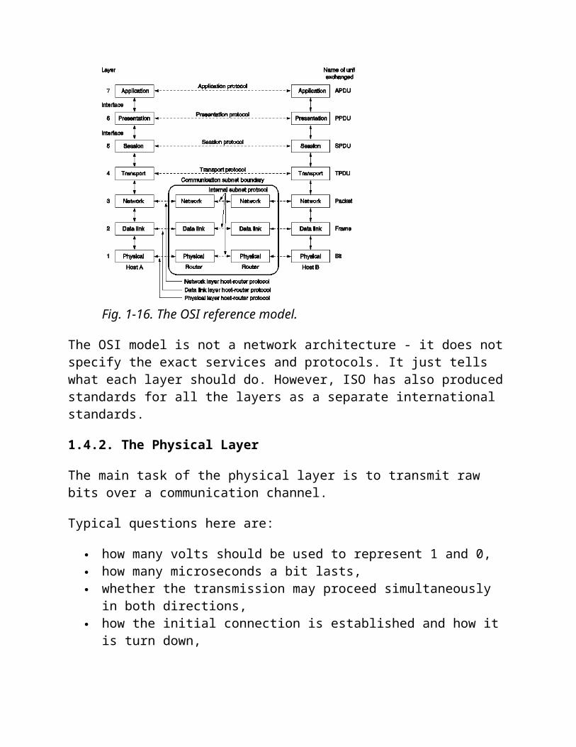
The OSI model has 7 layers (Fig. 1-16). The principles that were applied to arrive at the seven layers are as follows:
1. A layer should be created where a different level of abstraction is needed.2. Each layer should perform a well defined function.3. The function of each layer should be chosen with an eye toward defining
internationally standardized protocols.4. The layer boundaries should be chosen to minimize the information flow across
the interfaces.5. The number of layers should be large enough that distinct functions need not be
thrown together in the same layer out of necessity, and small enough that the architecture does not become unwieldy.
Fig. 1-16. The OSI reference model.
The OSI model is not a network architecture - it does not specify the exact services and protocols. It just tells what each layer should do. However, ISO has also produced standards for all the layers as a separate international standards.
1.4.2. The Physical Layer
The main task of the physical layer is to transmit raw bits over a communication channel.
Typical questions here are:
how many volts should be used to represent 1 and 0, how many microseconds a bit lasts, whether the transmission may proceed simultaneously in both directions, how the initial connection is established and how it is turn down, how many pins the network connector has and what each pin is used for.
The design issues deal with mechanical, electrical, and procedural interfaces, and the physical transmission medium, which lies below the physical layer.
The user of the physical layer may be sure that the given stream of bits was encoded and transmitted. He cannot be sure that the data came to the destination without error. This issue is solved in higher layers.
1.4.3. The Data Link Layer
The main task of the data link layer is to take a raw transmission facility and transform it into a line that appears free of undetected transmission errors to the network layer. To accomplish this, the sender breaks the input data into data frames (typically a few hundred or a few thousand bytes), transmits the frames sequentially, and processes the acknowledgment frames sent back by the receiver.
The issues that the layer has to solve:
to create and to recognize frame boundaries - typically by attaching special bit patterns to the beginning and end of the frame,
to solve the problem caused by damaged, lost or duplicate frames (the data link layer may offer several different service classes to the network layer, each with different quality and price),
to keep a fast transmitter from drowning a slow receiver in data, if the line is bi-directional, the acknowledgment frames compete for the use of
the line with data frames.
Broadcast networks have an additional issue in the data link layer: how to control access to the shared channel. A special sublayer of the data link layer (medium access sublayer) deals with the problem.
The user of the data link layer may be sure that his data were delivered without errors to the neighbor node. However, the layer is able to deliver the data just to the, neighbor node.
1.4.4. The Network Layer
The main task of the network layer is to determine how data can be delivered from source to destination. That is, the network layer is concerned with controlling the operation of the subnet.
The issues that the layer has to solve:
to implement the routing mechanism, to control congestions, to do accounting, to allow interconnection of heterogeneous networks.
In broadcast networks, the routing problem is simple, so the network layer is often thin or even nonexistent.
The user of the network layer may be sure that his packet was delivered to the given destination. However, the delivery of the packets needs not to be in the order in which they were transmitted.
1.4.5. The Transport Layer
The basic function of the transport layer is to accept data from the session layer, split it up into smaller units if need be, pass them to the network layer, and ensure that the pieces all arrive correctly at the other end. All this must be done in a way that isolates the upper layers from the inevitable changes in the hardware technology.
The issues that the transport layer has to solve:
to realize a transport connection by several network connections if the session layer requires a high throughput or multiplex several transport connections onto the same network connection if network connections are expensive,
to provide different type of services for the session layer, to implement a kind of flow control.
The transport layer is a true end-to-end layer, from source to destination. In other words, a program on the source machine carries on a conversation with a similar program on the destination machine. In lower layers, the protocols are between each machine and its immediate neighbors.
The user of the transport layer may be sure that his message will be delivered to the destination regardless of the state of the network. He need not worry about the technical features of the network.
1.4.6. The Session Layer
The session layer allows users on different machines to establish sessions between them. A session allows ordinary data transport, as does the transport layer, but it also provides enhanced services useful in some applications.
Some of these services are:
Dialog control - session can allow traffic to go in both directions at the same time, or in only one direction at a time. If traffic can go only in one way at a time, the session layer can help to keep track of whose turn it is.
Token management - for some protocols it is essential that both sides do not attempt the same operation at the same time. The session layer provides tokens that can be exchanged. Only the side holding the token may perform the critical action.
Synchronization - by inserting checkpoints into the data stream the layer eliminates problems with potential crashes at long operations. After a crash, only the data transferred after the last checkpoint have to be repeated.
The user of the session layer is in similar position as the user of the transport layer but having larger possibilities.
1.4.7. The Presentation Layer
The presentation layer perform certain functions that are requested sufficiently often to warrant finding a general solution for them, rather than letting each user solve the problem. This layer is, unlike all the lower layers, concerned with the syntax and semantics of the information transmitted.
A typical example of a presentation service is encoding data in a standard agreed upon way. Different computers may use different ways of internal coding of characters or numbers. In order to make it possible for computers with different representations to communicate, the data structures to be exchanged can be defined in an abstract way,
along with a standard encoding to be used "on the wire". The presentation layer manages these abstract data structures and converts from the representation used inside the computer to the network standard representation and back.
1.4.8. The Application Layer
The application layer contains a variety of protocols that are commonly needed.
For example, there are hundreds of incompatible terminal types in the world. If they have to be used for a work with a full screen editor, many problems arise from their incompatibility. One way to solve this problem is to define network virtual terminal and write editor for this terminal. To handle each terminal type, a piece of software must be written to map the functions of the network virtual terminal onto the real terminal. All the virtual terminal software is in the application layer.
Another application layer function is file transfer. It must handle different incompatibilities between file systems on different computers. Further facilities of the application layer are electronic mail, remote job entry, directory lookup ant others.
1.4.9. Data Transmission in the OSI Model
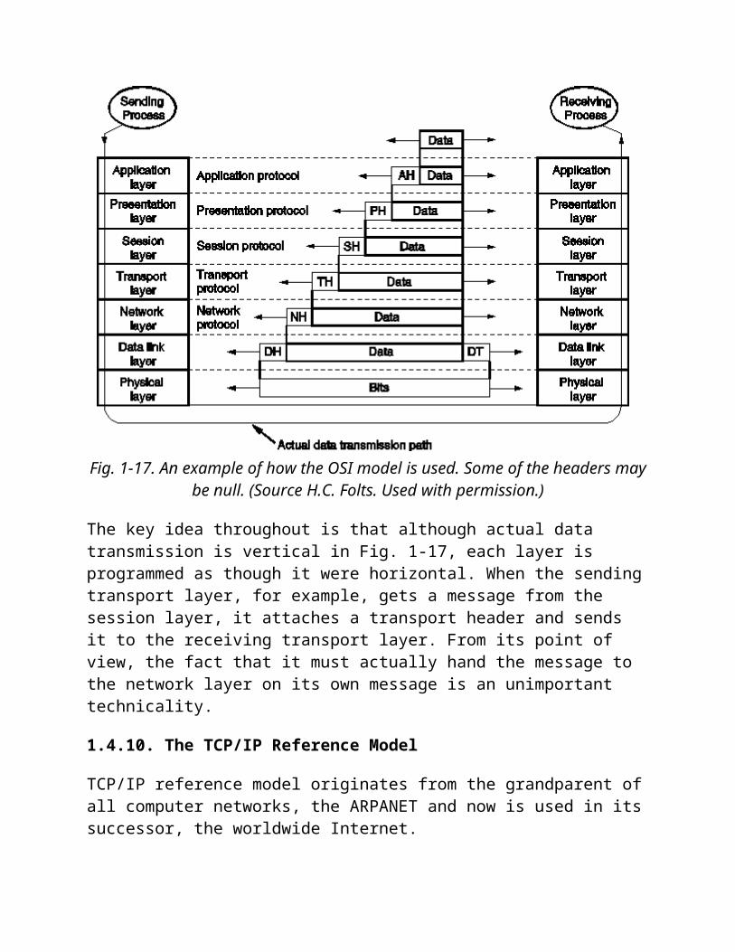
Figure 1-17 shows an example how data can be transmitted using OSI model.
Fig. 1-17. An example of how the OSI model is used. Some of the headers may be null.
(Source H.C. Folts. Used with permission.)
The key idea throughout is that although actual data transmission is vertical in Fig. 1-17, each layer is programmed as though it were horizontal. When the sending transport layer, for example, gets a message from the session layer, it attaches a transport header and sends it to the receiving transport layer. From its point of view, the fact that it must actually hand the message to the network layer on its own message is an unimportant technicality.
1.4.10. The TCP/IP Reference Model
TCP/IP reference model originates from the grandparent of all computer networks, the ARPANET and now is used in its successor, the worldwide Internet.
The name TCP/IP of the reference model is derived from two primary protocols of the corresponding network architecture.
1.4.11. The Internet Layer
The internet layer is the linchpin of the whole architecture. It is a connectionless internetwork layer forming a base for a packet-switching network. Its job is to permit
hosts to inject packets into any network and have them travel independently to the destination. It works in analogy with the (snail) mail system. A person can drop a sequence of international letters into a mail box in one country, and with a little luck, most of them will be delivered to the correct address in the destination country.
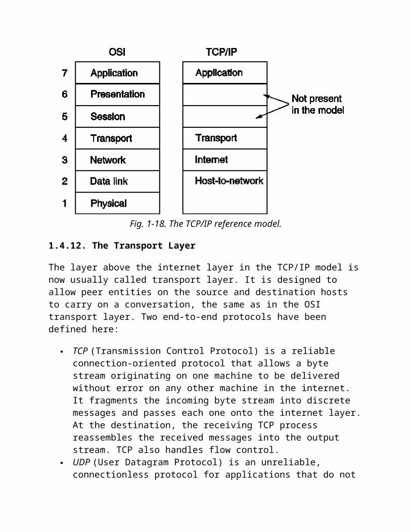
The internet layer defines an official packet format and protocol called IP (Internet Protocol). The job of the internet layer is to deliver IP packets where they are supposed to go. TCP/IP internet layer is very similar in functionality to the OSI network layer (Fig. 1-18).
Fig. 1-18. The TCP/IP reference model.
1.4.12. The Transport Layer
The layer above the internet layer in the TCP/IP model is now usually called transport layer. It is designed to allow peer entities on the source and destination hosts to carry on a conversation, the same as in the OSI transport layer. Two end-to-end protocols have been defined here:
TCP (Transmission Control Protocol) is a reliable connection-oriented protocol that allows a byte stream originating on one machine to be delivered without error on any other machine in the internet. It fragments the incoming byte stream into discrete messages and passes each one onto the internet layer. At the destination, the receiving TCP process reassembles the received messages into the output stream. TCP also handles flow control.
UDP (User Datagram Protocol) is an unreliable, connectionless protocol for applications that do not want TCP's sequencing or flow control and wish to provide their own. It is also widely used for one/shot, client/server type request/reply queries and applications in which prompt delivery is more important than accurate delivery.
1.4.13. The Application Layer
The application layer is on the top of the transport layer. It contains all the higher level protocols. Some of them are:
Virtual terminal (TELNET) - allows a user on one machine to log into a distant machine and work there.
File transfer protocol (FTP) - provides a way to move data efficiently from one machine to another.
Electronic mail (SMTP) - specialized protocol for electronic mail. Domain name service (DNS) - for mapping host names onto their network
addresses.
1.4.14. The Host-to-Network Layer
Bellow the internet layer there is a great void. The TCP/IP reference model does not really say much about what happens here, except to point out that the host has to connect to the network using some protocol so it can send IP packet over it. This protocol is not defined and varies from host to host and network to network.
1.4.15. The ARPANET Story
The ARPANET is the grandparent of all computer networks, the Internet is its successor. The milestones of the ARPANET:
In the mid 1960's, at the height of the Cold War, Department of Defense (DoD) wanted a command and control network that could survive a nuclear war. To solve this problem, DoD turned to its research arm Advanced Research Project Agency (ARPA).
ARPA was created in response to the Soviet Union's launching Sputnik in 1957 and had the mission of advancing technology that might be useful to the military. It did its work by issuing grants and contracts to universities and companies whose ideas looked promising to it.
ARPA decided that that the network the DoD needed should be a packet-switched network consisting of a subnet and host computers. The subnet would consist of minicomputers called IMPs (Interface Message Processors)
connected by transmission lines. Each IMP would be connected to at least two other IMPs. At each IMP, there would be a host.
ARPA put a tender for building the subnet and selected BBN, a consulting firm in Cambridge, Massachusetts for building the subnet and write the subnet software. The contract was signed in December 1968.
BBN chose to use specially modified Honeywell DDP-316 minicomputers with 12K 16-bit words of memory as the IMPs. They did not have disks and were interconnected by 56 kbps lines leased from telephone companies.
The software was split into two parts: subnet and host. The subnet software consisted of IMP end of the host-IMP connection, the IMP-IMP protocol, and a source IMP to destination IMP protocol. (Fig. 1-24).
Fig. 1-24. The original ARPANET design.
Host end of the host-IMP connection and host-host protocol as well as application software was written mostly by graduate students (BBN did not think it was their job).
The experimental network with 4 nodes went on air in December 1969 and grew quickly (Fig. 1-25).
Fig. 1-25. Growth of the ARPANET. (a) Dec. 1969. (b) July 1970. (C) March 1971. (d) April 1972. (e) Sept. 1972.
ARPA also funded research on satellite networks and mobile packet radio networks. In one famous demonstration a truck driving around California was connected with a computer in University College in London using packet radio network, ARPANET and satellite network.
It turned out that ARPANET protocols were not suitable for running over multiple networks. This observation led to the invention of the TCP/IP model and protocols (Cerf and Kahn, 1974) specifically designed to handle communication over internetworks.
University of California at Berkley integrated these new protocols to Berkley UNIX. The timing was perfect - many universities had just acquired new VAX computers with no networking software - they started to use Berkley software. With this software it was easy to connect to ARPANET.
By 1983, the ARPANET was stable and successful, with over 200 IMPs and hundreds of hosts. At this point ARPA the military portion (about 160 IMPs) was separated into a separate subnet MILNET, with stringent gateways between MILNET and the remaining research subnet.
During 1980s, additional networks were connected to ARPANET. DNS (Domain Naming System) was created to organize machines into domains and map host names onto IP addresses.
By 1990, the ARPANET has been overtaken by newer networks that it itself has spawned, so it was shut down and dismantled, but it lives in the hearts and minds of network researchers everywhere. MILNET continues to operate.
1.4.16. A Comparison of the OSI and TCP Reference Models
The OSI and the TCP/IP reference models have much in common:
they are based on the concept of a stack of independent protocols, they have roughly similar functionality of layers, the layers up and including transport layer provide an end-to-end network-
independent transport service to processes wishing to communicate.
The two models also have many differences (in addition to different protocols).
Probably the biggest contribution of the OSI model is that it makes the clear distinction between its three central concepts that are services, interfaces, and protocols.
Each layer performs some services for the layer above it. The service definition tells what the layer does, not how entities above it access it or how the layer works.
A layer's interface tells the processes above it how to access it including the specification of the parameters and the expected results. But it, too, says nothing about how the layer works inside.
The peer protocols used in a layer are its own business. It can use any protocol as long as it provides the offered services.
These ideas fit with modern ideas about object-oriented programming where a layer can be understood to be an object with a set of operations that processes outside the object can invoke.
The TCP/IP model did not originally clearly distinguish between service, interface, and protocol. As a consequence, the protocol in the OSI model are better hidden than in the TCP/IP model and can be replaced relatively easily as the technology changes.
The OSI reference model was devised before the protocols were invented. The positive aspect of this was that the model was made quite general, not biased toward
one particular set of protocols. The negative aspect was that the designers did not have much experience with the subject and did not have a good idea of which functionality to put into which layer (e.g. some new sublayers had to be hacked into the model).
With the TCP/IP the reverse was true: the protocols came first, and the model was just a description of the existing protocols. As a consequence, the model was not useful for describing other non-TCP/IP networks.
An obvious difference between the two models is the number of layers. Another difference is in the area of connectionless versus connection-oriented communication. The OSI model supports both types of communication in the network layer, but only connection-oriented communication in the transport layer. The TCP/IP model has only connectionless mode in the network layer but supports both modes in the transport layer. The connectionless choice is especially important for simple request-response protocols.
1.4.17. A Critique of the OSI Model and Protocols
At the end of 80s, it appeared that the OSI model were going to take over the world. This did not happen. The main reasons can be summarized as:
1. Bad timing.2. Bad technology.3. Bad implementation.4. Bad politics.
1.4.18. Bad Timing
The time at which a standard is established is absolutely critical to its success (a theory of the apocalypse of the two elephants). The standard for a new subject has to be written between the two "elephants": the burst of research activities on the new subject and the burst of investments to the new subject. If it is written too early, before the research is finished, the subject may still be poorly understood, which leads to bad standard. If it is written too late, companies have already made investment and the standard is ignored. If the interval between the two elephants is very short, the people developing the standard may get crushed.
It appears that the standard OSI got crushed because of the use of TCP/IP protocols by research universities by the time OSI protocols appeared. At that time many vendors had already begun offering TCP/IP products and did not want to support a second protocol stack until they were forced to, so there were no initial offerings. With every
company waiting for every other company to go first, no company went first and OSI never happened.
1.4.19. Bad Technology
The OSI model and the protocols are imperfect. Some layers are of little use or almost empty (the session, or the presentation layer), some are so full that subsequent work has split them into multiple sublayers, each with different functions (the data link, or the network layers). The real reason for 7 layers probably was that IBM had at the time when the OSI model was designed its proprietary seven-layered protocol called SNA (System Network Architecture).
The OSI model is extraordinarily complex. It is difficult to implement and inefficient in operation.
Perhaps the most serious criticism is that the model is dominated by a communications mentality.
1.4.20. Bad Implementation
Given the enormous complexity of the model and protocols, the initial implementations were huge, unwieldy, and slow. While the products got better in the course of time, the image stuck.
In contrast, the implementations of TCP/IP were good. People began to use them quickly which led to a large user community, which led to improvements, which led to an even large community and the spiral was upward.
1.4.21. Bad Politics
Many people, especially in academia, thought of TCP/IP as a part of UNIX, and UNIX in 1980s in academia was very popular.
OSI, on the other hand, was thought to be the creature of bureaucrats trying to shove a technically inferior standard down the throats of the poor researchers and programmers. It did not OSI help much.
But there are still a few organizations interested in OSI. Consequently, an effort has been made to update it, resulting in a (little) revised model published in 1994.
1.4.22. A Critique of the TCP/IP Reference model
The TCP/IP model and protocols have their problems to. The main of them are:
the model does not clearly distinguish the concepts of service, interface, and protocols (it does not fit into good software engineering practice).
TCP/IP model is not at all general and therefore it is poorly suited to describing any protocol stack other than TCP/IP.
The host-to-network layer is not really a layer at all in the normal sense. It is an interface between the network and data link layers.
The TCP/IP model does not distinguish, or even mention, the physical and data link layers.
Although the IP and the TCP protocols were carefully thought out, and well implemented, many of the other protocols were ad hoc, produced by a couple of graduate students hacking away until they got tired. They were distributed free, widely used, deeply entrenched, and thus hard to replace. Some of them are a bit of embarrassment now (TELNET was designed for slow terminals, it knows nothing of graphical user interface and mice, but it is still widely used).
In summary, despite its problems, the OSI model (minus the session and presentation layers) has proven to be exceptionally useful for discussing computer networks. In contrast, the OSI protocols have not become popular. The reverse is true of TCP/IP: the model is practically nonexistent, but the protocols are widely used.
Internet Protocol SuiteFrom Wikipedia, the free encyclopedia
Internet Protocol Suite
Application Layer
DHCP · DNS · FTP · HTTP · IMAP ·IRC · LDAP · MGCP · N
Integrated circuits are more expensive when they have more pins. To reduce the number of pins in a package,
many ICs use a serial bus to transfer data when speed is not important. Some examples of such low-cost serial
buses include SPI, I²C, UNI/O, and 1-Wire.
[edit]Serial versus parallel
The communication links across which computers—or parts of computers—talk to one another may be either
serial or parallel. A parallel link transmits several streams of data (perhaps representing particular bits of a
stream of bytes) along multiple channels (wires, printed circuit tracks, optical fibres, etc.); a serial link transmits
a single stream of data.
At first sight it would seem that a serial link must be inferior to a parallel one, because it can transmit less data
on each clock tick. However, it is often the case that serial links can be clocked considerably faster than parallel
links, and achieve a higher data rate. A number of factors allow serial to be clocked at a greater rate:
Clock skew between different channels is not an issue (for unclocked asynchronous serial
communication links)
A serial connection requires fewer interconnecting cables (e.g. wires/fibres) and hence occupies less
space. The extra space allows for better isolation of the channel from its surroundings
Crosstalk is less of an issue, because there are fewer conductors in proximity.
In many cases, serial is a better option because it is cheaper to implement. Many ICs have serial interfaces, as
opposed to parallel ones, so that they have fewer pins and are therefore less expensive.
[edit]Examples of serial communication architectures
Morse code telegraphy
RS-232 (low-speed, implemented by serial ports)
RS-422
RS-423
RS-485
I²C
SPI
ARINC 818 Avionics Digital Video Bus
Universal Serial Bus (moderate-speed, for connecting peripherals to computers)
FireWire
Ethernet
Fibre Channel (high-speed, for connecting computers to mass storage devices)
InfiniBand (very high speed, broadly comparable in scope to PCI)
MIDI control of electronic musical instruments
DMX512 control of theatrical lighting
SDI-12 industrial sensor protocol
Serial Attached SCSI
Serial ATA
SpaceWire Spacecraft communication network
HyperTransport
PCI Express
SONET and SDH (high speed telecommunication over optical fibers)
T-1, E-1 and variants (high speed telecommunication over copper pairs)
MIL-STD-1553A/B
In telecommunication and computer science, parallel communication is a method of sending several
data signals simultaneously over several parallel channels. It contrasts with serial communication; this
distinction is one way of characterizing a communications link.
The basic difference between a parallel and a serial communication channel is the number of distinct
wires or strands at the physical layer used for simultaneous transmission from a device. Parallel
communication implies more than one such wire/strand, in addition to a ground connection. An 8-bit
parallel channel transmits eight bits (or a byte) simultaneously. A serial channel would transmit those bits
one at a time. If both operated at the same clock speed, the parallel channel would be eight times faster.
A parallel channel will generally have additional control signals such as a clock, to indicate that the data is
valid, and possibly other signals for handshaking and directional control of data transmission.
Contents
[hide]
1 Examples of parallel communication systems
2 Comparison with serial links
3 References
4 See also
[edit]Examples of parallel communication systems
Computer peripheral buses: ISA, ATA, SCSI, PCI and Front side bus, and the once-ubiquitous IEEE-
1284 / Centronics "printer port"
Laboratory Instrumentation bus IEEE-488
(see more examples at Computer bus)
Circuit Vs Packet
The old telephone system (PSTN) uses circuit switching to transmit voice data whereas VoIP uses packet-switching to do so. The difference in the way these two types of switching work is the thing that made VoIP so different and successful.
To understand switching, you need to realize that the network in place between two communicating persons is a complex field of devices and machines, especially if the network is the Internet. Consider a person in Mauritius having a phone conversation with another person on the other side of the globe, say in the US. There are a large number of routers, switches and other kinds of
devices that take the data transmitted during the communication from one end to the other.
Switching and routing
Switching and routing are technically two different things, but for the sake of simplicity, let us takeswitches and routers (which are devices that make switching and routing respectively) as devices doing one job: make a link in the connection and forward data from the source to the destination.
Paths or circuits
The important thing to look for in transmitting information over such a complex network is thepath or circuit. The devices making up the path are called nodes. For instance, switches, routers and some other network devices, are nodes.
In circuit-switching, this path is decided upon before the data transmission starts. The system decides on which route to follow, based on a resource-optimizing algorithm, and transmission goes according to the path. For the whole length of the communication session between the two communicating bodies, the route is dedicated and
exclusive, and released only when the session terminates.
Packets
To be able to understand packet-switching, you need to know what a packet is. TheInternet Protocol(IP), just like many other protocols, breaks data into chunks and wraps the chunks into structures called packets. Each packet contains, along with the data load, information about the IP address of the source and the destination nodes, sequence numbers and some other control information. A packet can also be called a segment or datagram.
Once they reach their destination, the packets are reassembled to make up the original data again. It is therefore obvious that, to transmit data in packets, it has to be digital data.
In packet-switching, the packets are sent towards the destination irrespective of each other. Each packet has to find its own route to the destination. There is no predetermined path; the decision as to which node to hop to in the next step is taken only when a node is reached. Each packet finds its way using the information it carries, such as the source and destination IP addresses.
As you must have figured it out already, traditional PSTN phone system uses circuit switching while VoIP uses packet switching
Brief comparison
Circuit switching is old and expensive, and it is what PSTN uses. Packet switching is more modern.
When you are making a PSTN call, you are actually renting the lines, with all it implies. See why international calls are expensive? So if you speak for, say 10 minutes, you pay for ten minutes of dedicated line. You normally speak only when your correspondent is silent, and vice versa. Taking also into consideration the amount of time no one speaks, you finally use much less than half of what you are paying for. With VoIP, you actually can use a network or circuit even if there are other people using it at the same time. There is no circuit dedication. The cost is shared.
Circuit-switching is more reliable than packet-switching. When you have a circuit dedicated for a session, you are sure to get all information across. When you use a circuit which is open for other services, then there is a big possibility of congestion (which is for a network what a traffic jam is for the road), and hence the delays or even packet loss. This explains the relatively lower quality of VoIP voice compared to PSTN. But you actually have other protocols giving a helping
hand in making packet-switching techniques to make connections more reliable. An example is the TCP protocol. Since voice is to some extent tolerant to some packet loss (unless text - since a comma lost can mean a big difference), packet-switching is finally ideal for VoIP.
This article is about secure cryptographic signatures. For simple signatures in digital form, see Electronic signature.
A digital signature or digital signature scheme is a mathematical scheme for demonstrating the
authenticity of a digital message or document. A valid digital signature gives a recipient reason to believe
that the message was created by a known sender, and that it was not altered in transit. Digital signatures
are commonly used for software distribution, financial transactions, and in other cases where it is
important to detect forgery and tampering.
Digital signatures are often used to implement electronic signatures, a broader term that refers to any
electronic data that carries the intent of a signature,[1] but not all electronic signatures use digital
signatures.[2][3][4] In some countries, including the United States, India, and members of the European
Union, electronic signatures have legal significance. However, laws concerning electronic signatures do
not always make clear whether they are digital cryptographic signatures in the sense used here, leaving
the legal definition, and so their importance, somewhat confused.
Digital signatures employ a type of asymmetric cryptography. For messages sent through an
insecure channel, a properly implemented digital signature gives the receiver reason to believe the
message was sent by the claimed sender. Digital signatures are equivalent to traditional handwritten
signatures in many respects; properly implemented digital signatures are more difficult to forge than the
handwritten type. Digital signature schemes in the sense used here are cryptographically based, and
must be implemented properly to be effective. Digital signatures can also provide non-repudiation,
meaning that the signer cannot successfully claim they did not sign a message, while also claiming their
private key remains secret; further, some non-repudiation schemes offer a time stamp for the digital
signature, so that even if the private key is exposed, the signature is valid nonetheless. Digitally signed
messages may be anything representable as a bitstring: examples include electronic
mail, contracts, or a message sent via some other cryptographic protocol.
To create RSA signature keys, generate an RSA key pair containing a modulus N that is the product of
two large primes, along with integers e and d such that e d ≡ 1 (mod φ(N)), where φ is the Euler phi-
function. The signer's public key consists of N and e, and the signer's secret key contains d.
To sign a message m, the signer computes σ ≡ md (mod N). To verify, the receiver checks that
σe ≡ m (mod N).
As noted earlier, this basic scheme is not very secure. To prevent attacks, one can first apply
a cryptographic hash function to the message m and then apply the RSA algorithm described above
to the result. This approach can be proven secure in the so-called random oracle model[clarification
needed].
Other digital signature schemes were soon developed after RSA, the earliest being Lamport
signatures,[8] Merkle signatures (also known as "Merkle trees" or simply "Hash trees"),[9] andRabin
signatures.[10]
In 1988, Shafi Goldwasser, Silvio Micali, and Ronald Rivest became the first to rigorously define the
security requirements of digital signature schemes.[11] They described a hierarchy of attack models for
signature schemes, and also present the GMR signature scheme, the first that can be proven to
prevent even an existential forgery against a chosen message attack.[11]
Most early signature schemes were of a similar type: they involve the use of a trapdoor permutation,
such as the RSA function, or in the case of the Rabin signature scheme, computing square modulo
composite n. A trapdoor permutation family is a family of permutations, specified by a parameter, that
is easy to compute in the forward direction, but is difficult to compute in the reverse direction without
already knowing the private key. However, for every parameter there is a "trapdoor" (private key) which
when known, easily decrypts the message. Trapdoor permutations can be viewed as public-key
encryption systems, where the parameter is the public key and the trapdoor is the secret key, and where
encrypting corresponds to computing the forward direction of the permutation, while decrypting
corresponds to the reverse direction. Trapdoor permutations can also be viewed as digital signature
schemes, where computing the reverse direction with the secret key is thought of as signing, and
computing the forward direction is done to verify signatures. Because of this correspondence, digital
signatures are often described as based on public-key cryptosystems, where signing is equivalent to
decryption and verification is equivalent to encryption, but this is not the only way digital signatures are
computed.
Used directly, this type of signature scheme is vulnerable to a key-only existential forgery attack. To
create a forgery, the attacker picks a random signature σ and uses the verification procedure to determine
the message m corresponding to that signature.[12] In practice, however, this type of signature is not used
directly, but rather, the message to be signed is firsthashed to produce a short digest that is then signed.
This forgery attack, then, only produces the hash function output that corresponds to σ, but not a
message that leads to that value, which does not lead to an attack. In the random oracle model,
this hash-and-decrypt form of signature is existentially unforgeable, even against a chosen-message
attack.[6][clarification needed]
There are several reasons to sign such a hash (or message digest) instead of the whole document.
For efficiency: The signature will be much shorter and thus save time since hashing is generally
much faster than signing in practice.
For compatibility: Messages are typically bit strings, but some signature schemes operate on other
domains (such as, in the case of RSA, numbers modulo a composite numberN). A hash function can
be used to convert an arbitrary input into the proper format.
For integrity: Without the hash function, the text "to be signed" may have to be split (separated) in
blocks small enough for the signature scheme to act on them directly. However, the receiver of the
signed blocks is not able to recognize if all the blocks are present and in the appropriate order.
[edit]Notions of security
In their foundational paper, Goldwasser, Micali, and Rivest lay out a hierarchy of attack models against
digital signatures[11]:
1. In a key-only attack, the attacker is only given the public verification key.
2. In a known message attack, the attacker is given valid signatures for a variety of messages
known by the attacker but not chosen by the attacker.
3. In an adaptive chosen message attack, the attacker first learns signatures on arbitrary messages
of the attacker's choice.
They also describe a hierarchy of attack results[11]:
1. A total break results in the recovery of the signing key.
2. A universal forgery attack results in the ability to forge signatures for any message.
3. A selective forgery attack results in a signature on a message of the adversary's choice.
4. An existential forgery merely results in some valid message/signature pair not already known
to the adversary.
The strongest notion of security, therefore, is security against existential forgery under an adaptive
chosen message attack.
[edit]Uses of digital signatures
As organizations move away from paper documents with ink signatures or authenticity stamps, digital
signatures can provide added assurances of the evidence to provenance, identity, and status of an
electronic document as well as acknowledging informed consent and approval by a signatory. The United
States Government Printing Office (GPO) publishes electronic versions of the budget, public and private
laws, and congressional bills with digital signatures. Universities including Penn State, University of
Chicago, and Stanford are publishing electronic student transcripts with digital signatures.
Below are some common reasons for applying a digital signature to communications:
[edit]Authentication
Although messages may often include information about the entity sending a message, that information
may not be accurate. Digital signatures can be used to authenticate the source of messages. When
ownership of a digital signature secret key is bound to a specific user, a valid signature shows that the
message was sent by that user. The importance of high confidence in sender authenticity is especially
obvious in a financial context. For example, suppose a bank's branch office sends instructions to the
central office requesting a change in the balance of an account. If the central office is not convinced that
such a message is truly sent from an authorized source, acting on such a request could be a grave
mistake.
[edit]Integrity
In many scenarios, the sender and receiver of a message may have a need for confidence that the
message has not been altered during transmission. Although encryption hides the contents of a message,
it may be possible to change an encrypted message without understanding it. (Some encryption
algorithms, known as nonmalleable ones, prevent this, but others do not.) However, if a message is
digitally signed, any change in the message after signature will invalidate the signature. Furthermore,
there is no efficient way to modify a message and its signature to produce a new message with a valid
signature, because this is still considered to be computationally infeasible by most cryptographic hash
functions (seecollision resistance).
[edit]Non-repudiation
Non-repudiation, or more specifically non-repudiation of origin, is an important aspect of digital
signatures. By this property an entity that has signed some information cannot at a later time deny having
signed it. Similarly, access to the public key only does not enable a fraudulent party to fake a valid
signature. This is in contrast to symmetric systems, where both sender and receiver share the same
secret key, and thus in a dispute a third party cannot determine which entity was the true source of the
information.
[edit]Additional security precautions
[edit]Putting the private key on a smart card
All public key / private key cryptosystems depend entirely on keeping the private key secret. A private key
can be stored on a user's computer, and protected by a local password, but this has two disadvantages:
the user can only sign documents on that particular computer
the security of the private key depends entirely on the security of the computer
A more secure alternative is to store the private key on a smart card. Many smart cards are designed to
be tamper-resistant (although some designs have been broken, notably by Ross Anderson and his
students). In a typical digital signature implementation, the hash calculated from the document is sent to
the smart card, whose CPU encrypts the hash using the stored private key of the user, and then returns
the encrypted hash. Typically, a user must activate his smart card by entering a personal
identification number or PIN code (thus providingtwo-factor authentication). It can be arranged
that the private key never leaves the smart card, although this is not always implemented. If the smart
card is stolen, the thief will still need the PIN code to generate a digital signature. This reduces the
security of the scheme to that of the PIN system, although it still requires an attacker to possess the card.
A mitigating factor is that private keys, if generated and stored on smart cards, are usually regarded as
difficult to copy, and are assumed to exist in exactly one copy. Thus, the loss of the smart card may be
detected by the owner and the corresponding certificate can be immediately revoked. Private keys that
are protected by software only may be easier to copy, and such compromises are far more difficult to
detect.
[edit]Using smart card readers with a separate keyboard
Entering a PIN code to activate the smart card commonly requires a numeric keypad. Some card readers
have their own numeric keypad. This is safer than using a card reader integrated into a PC, and then
entering the PIN using that computer's keyboard. Readers with a numeric keypad are meant to
circumvent the eavesdropping threat where the computer might be running a keystroke logger,
potentially compromising the PIN code. Specialized card readers are also less vulnerable to tampering
with their software or hardware and are often EAL3certified.
[edit]Other smart card designs
Smart card design is an active field, and there are smart card schemes which are intended to avoid these
particular problems, though so far with little security proofs.
[edit]Using digital signatures only with trusted applications
One of the main differences between a digital signature and a written signature is that the user does not
"see" what he signs. The user application presents a hash code to be encrypted by the digital signing
algorithm using the private key. An attacker who gains control of the user's PC can possibly replace the
user application with a foreign substitute, in effect replacing the user's own communications with those of
the attacker. This could allow a malicious application to trick a user into signing any document by
displaying the user's original on-screen, but presenting the attacker's own documents to the signing
application.
To protect against this scenario, an authentication system can be set up between the user's application
(word processor, email client, etc.) and the signing application. The general idea is to provide some
means for both the user app and signing app to verify each other's integrity. For example, the signing
application may require all requests to come from digitally-signed binaries.
[edit]WYSIWYS
Main article: WYSIWYS
Technically speaking, a digital signature applies to a string of bits, whereas humans and applications
"believe" that they sign the semantic interpretation of those bits. In order to be semantically interpreted
the bit string must be transformed into a form that is meaningful for humans and applications, and this is
done through a combination of hardware and software based processes on a computer system. The
problem is that the semantic interpretation of bits can change as a function of the processes used to
transform the bits into semantic content. It is relatively easy to change the interpretation of a digital
document by implementing changes on the computer system where the document is being processed.
From a semantic perspective this creates uncertainty about what exactly has been
signed. WYSIWYS (What You See Is What You Sign) [13] means that the semantic interpretation of a
signed message cannot be changed. In particular this also means that a message cannot contain hidden
info that the signer is unaware of, and that can be revealed after the signature has been applied.
WYSIWYS is a desirable property of digital signatures that is difficult to guarantee because of the
increasing complexity of modern computer systems.
[edit]Digital signatures vs. ink on paper signatures
An ink signature can be easily replicated from one document to another by copying the image manually or
digitally. Digital signatures cryptographically bind an electronic identity to an electronic document and the
digital signature cannot be copied to another document. Paper contracts often have the ink signature
block on the last page, and the previous pages may be replaced after a signature is applied. Digital
signatures can be applied to an entire document, such that the digital signature on the last page will
indicate tampering if any data on any of the pages have been altered.
[edit]Some digital signature algorithms
RSA -based signature schemes, such as RSA-PSS
DSA and its elliptic curve variant ECDSA
ElGamal signature scheme as the predecessor to DSA, and variants Schnorr
signature and Pointcheval-Stern signature algorithm
Rabin signature algorithm
Pairing -based schemes such as BLS
Undeniable signatures
Aggregate signature - a signature scheme that supports aggregation: Given n signatures on n
messages from n users, it is possible to aggregate all these signatures into a single signature whose
size is constant in the number of users. This single signature will convince the verifier that the n users
did indeed sign the n original messages.
[edit]The current state of use — legal and practical
Digital signature schemes share basic prerequisites that— regardless of cryptographic theory or legal
provision— they need to have meaning:
1. Quality algorithms
Some public-key algorithms are known to be insecure, practicable attacks against them having
been discovered.
2. Quality implementations
An implementation of a good algorithm (or protocol) with mistake(s) will not work.
3. The private key must remain private
if it becomes known to any other party, that party can produce perfect digital signatures of
anything whatsoever.
4. The public key owner must be verifiable
A public key associated with Bob actually came from Bob. This is commonly done using a public
key infrastructure and the public key user association is attested by the operator of the PKI
(called a certificate authority). For 'open' PKIs in which anyone can request such an
attestation (universally embodied in a cryptographically protectedidentity certificate), the
possibility of mistaken attestation is non trivial. Commercial PKI operators have suffered several
publicly known problems. Such mistakes could lead to falsely signed, and thus wrongly attributed,
documents. 'closed' PKI systems are more expensive, but less easily subverted in this way.
5. Users (and their software) must carry out the signature protocol properly.
Only if all of these conditions are met will a digital signature actually be any evidence of who sent the
message, and therefore of their assent to its contents. Legal enactment cannot change this reality of the
existing engineering possibilities, though some such have not reflected this actuality.
Legislatures, being importuned by businesses expecting to profit from operating a PKI, or by the
technological avant-garde advocating new solutions to old problems, have enacted statutes and/or
regulations in many jurisdictions authorizing, endorsing, encouraging, or permitting digital signatures and
providing for (or limiting) their legal effect. The first appears to have been in Utah in the United States,
followed closely by the states Massachusetts and California. Other countries have also passed
statutes or issued regulations in this area as well and the UN has had an active model law project for
some time. These enactments (or proposed enactments) vary from place to place, have typically
embodied expectations at variance (optimistically or pessimistically) with the state of the
underlying cryptographic engineering, and have had the net effect of confusing potential users and
specifiers, nearly all of whom are not cryptographically knowledgeable. Adoption of technical standards
for digital signatures have lagged behind much of the legislation, delaying a more or less unified
engineering position on interoperability, algorithm choice, key lengths, and so on what the
engineering is attempting to provide.
See also: ABA digital signature guidelines
[edit]Industry standards
Some industries have established common interoperabiltity standards for the use of digital
signatures between members of the industry and with regulators. These include the Automotive
Network Exchange for the automobile industry and the SAFE-BioPharma Association for
the healthcare industry.
[edit]Using separate key pairs for signing and encryption
In several countries, a digital signature has a status somewhat like that of a traditional pen and
paper signature, like in the EU digital signature legislation. Generally, these provisions mean
that anything digitally signed legally binds the signer of the document to the terms therein. For that
reason, it is often thought best to use separate key pairs for encrypting and signing. Using the
encryption key pair, a person can engage in an encrypted conversation (e.g., regarding a real estate
transaction), but the encryption does not legally sign every message he sends. Only when both
parties come to an agreement do they sign a contract with their signing keys, and only then are they
legally bound by the terms of a specific document. After signing, the document can be sent over the
encrypted link. If a signing key is lost or compromised, it can be revoked to mitigate any future
transactions. If an encryption key is lost, a backup or key escrow should be utilized to continue
viewing encrypted content. Signing keys should never be backed up or escrowed.
NETWORKING
TYPES OF TOPOLOGYThe topology of a network refers to the configuration of cables, computers, and other peripherals.
Linear Bus Star Star-Wired Ring Tree Summary Chart
Linear Bus Ethernet and LocalTalk networks use a linear bus topology. File server, workstations, and peripherals (each hardware is a nodes) are connected to the main run linear cable.
Fig. 9. Linear Bus topology
StarEach node (file server, workstations, and peripherals) connected directly to a central network hub or concentrator. Data on a star network passes through the hub or concentrator before continuing to its destination. The hub or concentrator manages and controls all functions of the network. It also acts as a repeater for the data flow. Common with twisted pair cable, coaxial cable or fibre optic cable can also be used.
Fig. 10. Star topology
Star-wired Ring Externally star wired topology appear to be the same as a star topology. Internally, the MAU (multistation access unit) of a star-wired ring contains wiring that allows information to pass from one device to another in a circle or ring. The Token Ring protocol uses a star-wired ring topology. TreeThis is a combination of linear bus and star topologies. It consists of groups of star-configured workstations connected to a linear bus backbone cable (See fig. 4). Tree topologies allow for the expansion of an existing network.
Fig. 11. Tree topology
Summary Chart
Physical Topology Common Cable Common Protocol
Linear Bus Twisted PairCoaxialFibre
EthernetLocalTalk
Star Twisted PairFibre
EthernetLocalTalk
Star-Wired Ring Twisted Pair Token Ring
TreeTwisted PairCoaxialFibre
Ethernet
Table 4
Token Ring
Token Ring was developed by several manufacturers and it copes well with high network traffic loadings, and were at one time extremely popular. The Ethernet has since overtaken their popularity. more
Contention Bus
Example commonly used Ethernet Uses Carrier Sense Multiple Access with Collision Detection (CSIVIA/CD) Nodes can transmit at the same time Detection of collision results in jamming signal Conflicting nodes wait for a random time Priority can be given by reducing the time.
IEEE Standards
Institute of Electrical and Electronic Engineers
LAN standards by the 802 committee802.2 LLC
802.3CSMA/CD. ffithernet)802.4 Token Bus802.5 Token Ring802.6 Metropolitan Area Network (MAN)
ETHERNET Computers in business now connect through a LAN and the most commonly used LAN is the Ethernet. Ethernet cannot on itself make a network and needs some form of protocol such as TCP/IP to allow nodes to communicate.
Ethernet networks are easy to plan and cheap to install. Ethernet network components, such as net work cards and connectors, are cheap and well
supported. It is a well-proven technology, which is fairly robust and reliable. It is simple to add and delete computers on the network. It is supported by most software and hardware systems.
Ethernet uses a shared-media, bus type network topology where all nodes share a common bus. Data is transmitted in frames which contain the MAC (media access control) source and destination addresses of the sending and receiving node, respectively. Collisions can occur when two nodes transmit at the same time, thus nodes must monitor the cable when they transmit. To avoid collision the Ethernet uses carrier sense, multiple access with collision detection (CSMA/CD) to monitor the bus (or Ether) to determine if it is busy. If a node wishes to transmit it waits for an ideal condition when no other node is transmitting. When a collision occurs, both nodes stop transmitting frames and transmit a jamming signal. This informs all nodes on the network that a collision has occurred. The nodes involved in the collision then waits a random period of time before attempting a re-transmission.
CSMA/CD
Each node on the network must be able to detect collisions and be capable of transmitting and receiving simultaneously.
NETWORKING HARDWARE
This includes all computers, peripherals, interface cards and other equipment needed to perform data processing and communications within the network.
The heart of most network is the file server. They are fast computers large RAM and storage space with a fast network interface card. Network operating system software, application software and data files resides on this server. The file server controls the communication of information between the nodes on a network. Sends and receive data from the workstations and store an e-mail message during the same time period. This requires a computer that can store a lot of information and share it very quickly.
Characteristics: Faster microprocessor (Pentium, PowerPC), A fast hard drive, A RAID (Redundant Array of Inexpensive Disks) to preserve data after a disk casualty, A tape back-up unit (i.e. DAT, JAZ, Zip, or CD-RW drive), Numerous expansion slots, Fast network interface card, At least of 32 MB of RAM
Workstations
PCs or Mac configured with the network interface card, network software connected to the file server with appropriate cable.
Network Interface Card(NIC)
Provides the physical connection between the network and the computer workstation.
NIC are major factor in determining the speed and performance of a network
Ethernet Cards
This is becoming a standard for PCs. Macintosh includes an option for a pre-installed Ethernet card (Fig 2). Ethernet cards contain connections for either coaxial or twisted pair cables (or both). For twisted pair connection RJ-45 connection will be used
Fig. 2. Ethernet card. From top to bottom:
RJ-45, AUI, and BNC connectors
LocalTalk Connectors
In apple Mac a built-in connector is available. This utilizes a special adapter box and a cable that plugs into the printer port of a Macintosh.
Ethernet Cards vs. LocalTalk Connections
Ethernet LocalTalk
Fast data transfer (10 to 100 Mbps) Slow data transfer (.23 Mbps)
Expensive - purchased separately Built into Macintosh computers
Requires computer slot No computer slot necessary
Available for most computers Works only on Macintosh computers
Table 1.
Token Ring Cards
Similar to Ethernet cards but different with the type of connector on the back end of the card.
SWITCH
Switch provides a central connection point for cables from workstations, servers, and peripherals. In a star topology, twisted-pair wire is run from each workstation to a central concentrator.
HUBS
Hubs are multislot concentrators into which can be plugged a number of multi-port cards to provide additional access as the network grows in size. Some concentrators are passive, that is, they allow the signal to pass from one computer to another without any change.
REPEATERS
Boost signal strength that is it weakens along a cable during transmission from one point to another by electrically amplifying the signal it receives and rebroadcasts it. Repeaters can be separate devices or they can be incorporated into a concentrator. They are used when the total length of your network cable exceeds the standards set for the type of cable being used.
BRIDGES
A bridge is a device used to segment a large network into two smaller, more efficient networks.
FIREWALL
Firewall is a barrier that protects your network from uninvited intruders, unauthorized users, and hackers. It provides a filter that incoming or outgoing packets must pass through. Every private network that is going to be connected to the Internet needs an appropriate firewall, being some combination of hardware, software, and procedures, to protect it.
ROUTERS
A router translates information from one network to another to prevent head-on collisions, and is smart enough to know when to direct traffic along back roads and shortcuts. For Internet connection a router is used as a translater.
NETWORK CABLING
Different types of cables are used in the LANs. Network Topology and size determines the type of cable to be used. More information on the type of cables
NETWORKSA network consists of two or more computers that are linked in order to share resources (such as printers and CD-ROMs), exchange files, or allow electronic communications. The computers on a network may be linked through cables, telephone lines, radio waves, satellites, or infrared light beams.
TYPES OF NETWORKS
The three basic types of networks include: LAN, MAN and WAN.
LOCAL AREA NETWORK (LAN)
A network is said to be Local Area Network (LAN) if it is confined relatively to a small area. It is generally limited to a building or a geographical area, expanding not more than a mile apart to other computers.
LAN configuration consist of:
o A file server - stores all of the software that controls the network, as well as the software that can be shared by the computers attached to the network.
o A workstation - computers connected to the file server (Mac or PCs). These are less powerful than the file server
o Cables - used to connect the network interface cards in each computer.
METROPOLITAN AREA NETWORK (MAN)
Metropolitan Area Network (MAN) covers larger geographic areas, such as cities. Often used by local libraries and government agencies often to connect to citizens and private industries.
WIDE AREA NETWORK (WAN)
Wide Area Networks (WANs) connect larger geographic areas, such as London, the UK, or the world. In this type of network dedicated transoceanic cabling or satellite uplinks may be used.
ADVANTAGES OF NETWORK
Speed. Sharing and transferring files within Networks are very rapid. Thus saving time, while maintaining the integrity of the file.
Cost. Individually licensed copies of many popular software programs can be costly. Networkable versions are available at considerable savings. Shared programs, on a network allows for easier upgrading of the program on one single file server, instead of upgrading individual workstations.
Security. Sensitive files and programs on a network are passwords protected (established for specific directories to restrict access to authorized users) or designated as "copy inhibit," so that you do not have to worry about illegal copying of programs.
Centralized Software Management. Software can be loaded on one computer (the file server) eliminating that need to spend time and energy installing updates and tracking files on independent computers throughout the building.
Resource Sharing. Resources such as, printers, fax machines and modems can be shared.
Electronic Mail. E-mail aids in personal and professional communication. Electronic mail on a LAN can enable staff to communicate within the building having tot to leave their desk.
Flexible Access. Access their files from computers throughout the firm.
Workgroup Computing. Workgroup software (such as Microsoft BackOffice) allows many users to work on a document or project concurrently.
DISADVANTAGES OF NETWORK
Server faults stop applications being available Network faults can cause loss of data. Network fault could lead to loss of resources User work dependent upon network System open to hackers Decisions tend to become centralised Could become inefFicient Could degrade in performance Resources could be located too far from users Network management can become dif
OSI MODELS
The standard model for networking protocols and distributed applications is the International Standard Organization's Open System Interconnect (ISO/OSI) model. It defines seven network layers.
Layer 1 - Physical
This layer defines the cable or physical medium itself, e.g. unshielded twisted pairs (UTP). All media of transmission are functionally equivalent in this layer and the main difference is in convenience and cost of installation and maintenance.
Layer 2 - Data Link
Data Link layer defines the format of data on the network ( a network data frame, packet and destination address). The Maximum Transmission Unit (MTU) is defined by the largest packet that can be sent through a data link layer.
Layer 3 - Network
This layer defines the protocols that are responsible for data delivery at the required destination, and requires.
Layer 4 - Transport
This layer subdivides user-buffer into network-buffer sized datagrams and enforces desired transmission control. Two transport protocols, Transmission Control Protocol (TCP) and User Datagram Protocol (UDP), sits at the transport layer. Reliability and speed are the primary difference between these two protocols.
This leyer defines the format of the data sent over the connections.
Layer 6 - Presentation
This layer converts local representation of data to its canonical form and vice versa. The canonical uses a standard byte ordering and structure packing convention, independent of the host.
Layer 7 - Application
Provides network services to the end-users. e.g Mail.
OSI Model gives; Increased evolution, Modular engineering, Interoperable technology, Reduced complexitySimplified teaching and learning, Standardised interfaces.
INTERNETWORKING
Internetwork is a collection of individual networks, connected by intermediate networking devices, that functions as a single large network.
Different Network Technologies Can Be Connected to Create an Internetwork
Internetworking devices have many advan tages and they are:
Increases the number of nodes that can connect to the network thus limitations on the number of nodes that connect to a network relate to the cable lengths and traffic constraints.
Extends the physical distance of the network.
They localize traffic within a network.
Merge existing networks.
Isolate network faults.
Typical internetworking devices are:
Repeater. Operate at Layer 1 of the OSI
Bridges. Passes data frames between net-works using the MAC address (Layer 2 address).
Hubs. Allow the interconnection of nodes and create a physically attached network.
Switches. Allow simultaneous communication between two or more nodes, at a time.
Routers. Passes data packets between connected networks, and operate on network addresses (Layer 3 address).
BROADCASTS
Todetermine the network address of a computer, the host send out broadcast to all the host on its network segment. There are two types:
Requests for a destination MAC addresses. A broadcast is sent to all the hosts on the network segment. A host with matching network address responds back with its MAC address in the source MAC address field. The MAC and the network address is stored in the memory of the host so that they can be used in the future communication. Known as Address Resolutions Protocol (ARP).
Requests for a network address. A host sends out a request with the MAC address if it does not know network address for a given MAC address. A server on the network responds back with the network address for the given MAC address. Known as Reverse Address Resolution Protocol (RARP).
Most networking technologies have a special MAC address for a broadcast. Ethernet uses the address: FF-FF-FF-FF-FF-FF for a broadcast. There are also network broadcast addresses using the network address (known as multicast) - all nodes on the network listen to the communication (such as transmitting a video conference to many nodes on a network, at the same time), but they are used for different purposes than with broadcast MAC addresses, which are used to get network information.
Broadcast for MAC Address
BITS, FRAMES, PACKETS AND SEGMENTS
At each nodes each of the OSI layers communicates directly with the equivalent layer on the receiving host. The data that is transmitted in each of the lower layers is referred to in a different way. Protocol data units (PDUs) are the data that passes from layer to layer and are referred to in different ways in each of the layers (bits - at the physical, frames - at the data link layer, packets - at the network layer they, and segments - at the transport layer).
Preamble 7 bytes Start delimiter 1 byte DSAP 1Destination address 6 SSAP 1Source address 6 Control field 1/2Length 2 DataData field L2L46-1500FCS 4
IEEE 802.5 frame format
Startclelimiter 1 byteAccess control 1 byteFrame control 1Destination address 6Source address 6DataFCS 4End delimiter 1Frame status 1
Token Start delimiter
1 Access control Priority 3 bits Token 1 bit Monitor 1 Reservation 3 bits End delimiter 1
PROTOCOL
A protocol is a set of rules that governs the communications between computers on a network. These rules are guidelines that regulate the access method, allowed physical topologies, types of cabling, and speed of data transfer.
The most common protocols are:
o Etherneto LocalTalko Token Ringo FDDIo ATM
ETHERNET
This is the most widely used protocol. This protocol uses an access method called CSMA/CD (Carrier Sense Multiple Access/Collision Detection). In this system each computer listens to the cable for any transmitting node before sending anything through the network. If the network is clear, the computer will transmit. Else wait and try again when the line is clear. Sometimes, two computers attempt to transmit at the same instant (causing a collision). Each computer then backs off and waits a random amount of time before attempting to retransmit. The delay by collisions and retransmitting is very small and does not normally affect the speed of transmission on the network.
Topologies are bus star or tree and transmission is via twisted pair, coaxial, or fibre optic cable at a speed of 10 Mbps.
Fast Ethernet
Support 100Mbps and are more expensive network concentrators/hubs and network interface cards is requires for Fast Ethernet. Category 5 twisted pair or fibre optic cable is necessary.
Gigabit Ethernet
The Ethernet has a standard protocol of 1Gbps transmission speed but used primarily for backbones on a network.
LOCALTALK
Apple Computer developed LocalTalk for Macintosh computers. The method used by LocalTalk is called CSMA/CA (Carrier Sense Multiple Access with Collision Avoidance). It is similar to CSMA/CD except that a computer signals its intent to transmit before it actually does so. LocalTalk adapters and special twisted pair cable can be used to connect a series of computers through the serial port.
LocalTalk protocol allows for linear bus, star, or tree topologies using twisted pair cable.
TOKEN RING
This was developed by IBM in the mid 1980s. The method used involves token-passing. Computers are connected so that the signal travels around the network from one computer to another in a logical ring. A single electronic token moves around the ring from one computer to the next. If a computer does not have information to transmit, it simply passes the token on to the next workstation. If a computer wishes to transmit and receives an empty token, it attaches data to the token. The token then proceeds around the ring until it comes to the computer for which the data is meant. At this point, the receiving computer captures the data.
FIBRE DISTRIBUTED DATA INTERFACE (FDDI)
Access method of token-passing via a dual ring physical topology. Transmission on one of the rings; however, if a break occurs, the system keeps information moving by automatically using portions of the second ring to create a new complete ring. Transmison speed is100 Mbps over a fibre optic cable, but expensive.
ASYNCHRONOUS TRANSFER MODE (ATM)
Transmits data in small packets of a fixed size at a speed of 155 Mbps and higher. ATM supports a variety of media such as video, CD-quality audio, and imaging. ATM employs a star topology with fibre optic or twisted pair cabling.
WIRELESS LANS
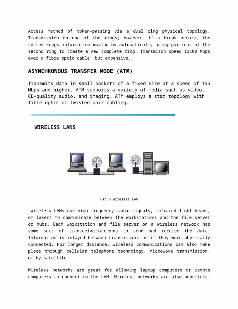
Fig 8 Wireless LAN
Wireless LANs use high frequency radio signals, infrared light beams, or lasers to communicate between the workstations and the file server or hubs. Each workstation and file server on a wireless network has some sort of transceiver/antenna to send and receive the data. Information is relayed between transceivers as if they were physically connected. For longer distance, wireless communications can also take place through cellular telephone technology, microwave transmission, or by satellite.
Wireless networks are great for allowing laptop computers or remote computers to connect to the LAN. Wireless networks are also beneficial in older buildings where it may be difficult or impossible to install cables.
This includes all computers, peripherals, interface cards and other equipment needed to perform data processing and communications within the network.
RS232
In telecommunications, RS-232 (Recommended Standard 232) is a standard for serial binary single-
ended data and control signals connecting between a DTE (Data Terminal Equipment) and a DCE (Data
Circuit-terminating Equipment). It is commonly used in computer serial ports. The standard defines the
electrical characteristics and timing of signals, the meaning of signals, and the physical size and pinout of
connectors.
Scope of the standard
The Electronics Industries Association (EIA) standard RS-232-C[1] as of 1969 defines:
Electrical signal characteristics such as voltage levels, signaling rate, timing and slew-rate of signals,
voltage withstand level, short-circuit behavior, and maximum load capacitance.
Interface mechanical characteristics, pluggable connectors and pin identification.
Functions of each circuit in the interface connector.
Standard subsets of interface circuits for selected telecom applications.
The standard does not define such elements as
character encoding (for example, ASCII, Baudot code or EBCDIC)
the framing of characters in the data stream (bits per character, start/stop bits, parity)
protocols for error detection or algorithms for data compression
bit rates for transmission, although the standard says it is intended for bit rates lower than 20,000 bits
per second. Many modern devices support speeds of 115,200 bit/s and above
The RS449 interface is a generic connector specification. It´s not an actual interface. The connector pinning was originally designed to support RS422 for balanced signals, and RS423 for the unbalanced signals. And should have been the succesor of RS232.
RS449 is a high speed digital interface - unlike RS232 which uses signals with reference to ground,
RS449 V.11 receivers look for the difference between two wires. By twisting the two wires and making a
"twisted pair" any stray noise picked up on one wire will be picked up on the other, because both wires
pick up the same noise the RS449 differential interface just shifts in voltage level with reference to
ground, but does not change with respect to each other. The receivers are only looking at the difference
in voltage level of each wire to the other not to ground.
The differential signals for RS449 are labeled as either "A and B" or "+ and -". In the case of RS449 wire
A or + does not connect to B or -. Wire A always connects to A and B connects to B or + to + and - to -. If
you do cross the wires you just inverted the data or clock in your interface and they don"t work - be sure
to check the polarities .
Common names: EIA-449, RS-449, ISO 4902.
Primary channel
Pin Name V.24 Dir Description Type
1 101 Shield Ground
2 SI 112 Signal Rate Indicator Control
3 n/a n/a unused
4 SD- 103 Send Data (A) Data
5 ST- 114 Send Timing (A) Timing
6 RD- 104 Receive Data (A) Data
7 RS- 105 Request To Send (A) Control
8 RT- 115 Receive Timing (A) Timing
9 CS- 106 Clear To Send (A) Control
10 LL 141 Local Loopback Control
11 DM- 107 Data Mode (A) Control
12 TR- 108.2 Terminal Ready (A) Control
13 RR- 109 Receiver Ready (A) Control
14 RL 140 Remote Loopback Control
15 IC 125 Incoming Call Control
16 SF/SR+ 126 Signal Freq./Sig. Rate Select. Control
17 TT- 113 Terminal Timing (A) Timing
18 TM- 142 Test Mode (A) Control
19 SG 102 Signal Ground Ground
20 RC 102b Receive Common Ground
21 n/a n/a unused
22 SD+ 103 Send Data (B) Data
23 ST+ 114 Send Timing (B) Timing
24 RD+ 104 Receive Data (B) Data
25 RS+ 105 Request To Send (B) Control
26 RT+ 115 Receive Timing (B) Timing
27 CS+ 106 Clear To Send (B) Control
28 IS n/a Terminal In Service Control
29 DM+ 107 Data Mode (B) Control
30 TR+ 108.2 Terminal Ready (B) Control
31 RR+ 109 Receiver Ready (B) Control
32 SS 116 Select Standby Control
33 SQ 110 Signal Quality Control
34 NS n/a New Signal Control
35 TT+ 113 Terminal Timing (B) Timing
36 SB 117 Standby Indicator Control
37 SC 102a Send Common Ground
Note: Direction is DTE (Computer) relative DCE (Modem).
Name
Description Function
AA Shield GroundAlso known as protective ground. This is the chassis ground connection between DTE and DCE.
AB Signal Ground The reference ground between a DTE and a DCE. Has the value 0 Vdc.
BA Transmitted Data Data send by the DTE.
BB Received Data Data received by the DTE.
CA Request To Send Originated by the DTE to initiate transmission by the DCE.
CB Clear To Send Send by the DCE as a reply on the RTS after a delay in ms, which gives the DCEs enough
time to energize their circuits and synchronize on basic modulation patterns.
CC DCE ReadyKnown as DSR. Originated by the DCE indicating that it is basically operating (power on, and in functional mode).
CD DTE ReadyKnown as DTR. Originated by the DTE to instruct the DCE to setup a connection. Actually it means that the DTE is up and running and ready to communicate.
CE Ring IndicatorA signal from the DCE to the DTE that there is an incomming call (telephone is ringing). Only used on switched circuit connections.
CFReceived Line Signal Detector
Known as DCD. A signal send from DCE to its DTE to indicate that it has received a basic carrier signal from a (remote) DCE.
CH/CIData Signal Rate Select(DTE/DCE Source>
A control signal that can be used to change the transmission speed.
DATransmit Signal Element Timing(DTE Source)
Timing signals used by the DTE for transmission, where the clock is originated by the DTE and the DCE is the slave.
DBTransmitter Signal Element Timing(DCE Source)
Timing signals used by the DTE for transmission.
DDReceiver Signal Element Timing(DCE Source)
Timing signals used by the DTE when receiving data.
IS terminal In Service Signal that indicates that the DTE is available for operation
NS New SignalA control signal from the DTE to the DCE. It instructs the DCE to rapidly get ready to receive a new analog signal. It helps master-station modems rapidly synchronize on a new modem at a tributary station in multipoint circuits
RC Receive Common A signal return for receiver circuit reference
LLLocal Loopback / Quality Detector
A control signal from the DTE to the DCE that causes the analog transmision output to be connected to the analog receiver input.
RL Remote LoopbackSignal from the DTE to the DCE. The local DCE then signals the remote DCE to loopback the analog signal and thus causing a line loopback.
SB Standby IndicatorSignal from the DCE to indicate if it is uses the normal communication or standby channel
SC Send Common A return signal for transmitter circuit reference
SF Select FrequencyA signal from the DTE to tell the DCE which of the two analog carrier frequencies should be used.
SS Select StandbyA signal from DTE to DCE, to switch between normal communication or standby channel.
TM Test Mode A signal from the DCE to the DTE that it is in test-mode and can"t send any data.
Reserved for Testing
The EIA RS449 standard specifies the functional and mechanical characteristics of the RS449
interconnection between the data terminal equipment (DTE) in the data communications equipment
(DCE) complying to EIA electrical interface standards RS 422 and RS 423.
X.21
The X.21 Interface
CCITT X21 is a physical and electrical interface that uses two types of circuits: balanced (X.27N.1 1) and and unbalanced (X.26N.10). CCITT X.21 calls out the DA-15 (also know by DB-15) connector.
The physical interface between the DTE and the local PTT-supplied DCE is defined in ITU-T recommendation X.21. The DCE provides a full-duplex, bit-serial, synchronous transmission path between the DTE and the local PSE. It can operate at data rates from 600bps to 64Kbps. A second standard, X.21bis has been defined for use on existing (analogue) networks. An X.21bis is a subset of EIA-232D/V.24 therefore allowing existing user equipment to be
readily interfaced using this standard. It should perhaps be emphasized here that V24 defines the data terminal equipment interface to the modem and is not concerned with the interface between the modem and the line itself. The modems themselves therefore form part of the conceptual physical connection. The V24 interface is thus independent of both modulation technique and data throughput rate.
The X.21 interface protocol is concerned only with the set-up and clearing operations between DTE and DCE associated with each call. The control of the ensuing data transfer is the responsibility of the link layer.
X21 Overview
X.21 is a state-driven protocol running full duplex at 9600 bps to 64 Kbps with subscriber networks. It is a circuit-switching protocol using Synchronous ASCII with odd parity to connect and disconnect a subscriber to the public-switching network.
The data-transfer phase is transparent to the network. Any data can be transferred through the network after Call Establishment is made successfully via the X.21 protocol. The call-control phases which are used were defined in the CCITT (now ITU) 1988 "Blue Book" Recommendations X.1 - X.32.
Signals Provided
The signals of the X21 interface are presented on a 15-pin connector defined by ISO Document 4903. The electrical characteristics are defined in CCITT Recommendations X.26 and X.27, which refer to CCITT Recommendations V.10 and V.11.
X.21 provides eight signals:
Signal Ground (G) -This provides reference for the logic states against the other circuits. This signal may be connected to the protective ground (earth).
DTE Common Return (Ga) -
Used only in unbalanced-type configurations (X.26), this signal provides reference ground for receivers in the DCE interface.
Transmit (T) -
This carries the binary signals which carry data from the DTE to the DCE. This circuit can be used in data-transfer phases or in call-control phases from the DTE to DCE (during Call Connect or Call Disconnect).
Receive (R) -
Controlled by the DTE to indicate to the DCE the meaning of the data sent on the transmit circuit. This circuit must be ON during data-transfer phase and can be ON or OFF during call-control phases, as defined by the protocol.
Indication (I) -
The DCE controls this circuit to indicate to the DTE the type of data sent on the Receive line. During data phase, this circuit must be ON and it can be ON or OFF during call control, as defined by the protocol.
Signal Element Timing (S) -
This provides the DTE or DCE with timing information for sampling the Receive line or Transmit line. The DTE samples at the correct instant to determine if a binary 1 or 0 is being sent by the DCE. The DCE samples to accurately recover signals at the correct instant. This signal is always ON.
Byte Timing (B) -
This circuit is normally ON and provides the DTE with 8-bit byte element timing. The circuit transitions to OFF when the Signal Element Timing circuit samples the last bit of an 8-bit byte. Call-control characters must align with the B lead during call-control phases. During data- transfer phase, the communicating devices bilaterally agree to use the B lead to define the end of each transmitted or received byte. The C and I leads then only monitor and record changes in this condition when the B lead changes from OFF to ON, although the C and I leads may be altered by the transitions on the S lead. This lead is frequently not used.
X.21 Protocol Operation
As stated previously, X.21 is a state protocol. Both the DTE and DCE can be in a Ready or Not-Ready state.
The Ready state for the DTE is indicated by a continuous transmission of binary 1's on the T lead. The Ready state for the DCE is continuous transmission of binary 1's on the R lead. During this continuous transmission of Ready state, the control leads are OFF.
During the Not-Ready state, the DCE transmits binary 0's on the R lead with the I lead in the OFF state.
The DTE Uncontrolled Not-Ready is indicated by transmission of binary 0's with the C lead in the OFF state. The DTE Uncontrolled Not-Ready state signifies that the DTE is unable to accept calls due to an abnormal condition.
The DTE Controlled Not-Ready state sends a pattern of alternating 1's and 0's on the T lead with the C lead OFF. This state indicates that the DTE is operational, but unable to accept incoming calls.
The characters sent between the DTE and DCE during call-control phases are International Alphabet 5 (IA5), defined by CCITT Recommendation V.3. At least two Sync characters must precede all sequences of characters sent between the DTE and DCE to establish 8-bit byte synchronization between the transmitter and the receiver. If the Byte Timing (B) lead is used, these Sync characters must align with the B lead timing signals.
Electrical Characteristics.
Data signaling rates of 9600 bit/s and below. X.27 (= V. 11) & X.26 (= V. 10)
Data signaling rates above 9600 bps. X.27 (= V. 11)
[V.10 specifies an interface circuit with an unbalanced transmitter with a differential receiver.]
[V.11 specifies an interface circuit with a differential, balanced signal from transmitter to receiver which may accommodate an optional DC offset voltage. This approximates EIA-4221
X.21 Overview
X.21 is a state-driven protocol running full duplex at 9600 bps to 64 Kbps with subscriber networks. It is a circuit-switching protocol using Synchronous ASCII with odd parity to connect and disconnect a subscriber to the public-switching network.
The data-transfer phase is transparent to the network. Any data can be transferred through the network after Call Establishment is made successfully via the X.21 protocol. The call-control phases which are used were defined in the CCITT (now ITU) 1988 "Blue Book" Recommendations X.1 - X.32.
Signals Provided
The signals of the X.21 interface are presented on a 15-pin connector defined by ISO Document 4903. The electrical characteristics are defined in CCITT
Recommendations X.26 and X.27, which refer to CCITT Recommendations V.10 and V.11.
X.21 provides eight signals:
Signal Ground (G) -
This provides reference for the logic states against the other circuits. This signal may be connected to the protective ground (earth).
DTE Common Return (Ga) -
Used only in unbalanced-type configurations (X.26), this signal provides reference ground for receivers in the DCE interface.
Transmit (T) -
This carries the binary signals which carry data from the DTE to the DCE. This circuit can be used in data-transfer phases or in call-control phases from the DTE to DCE (during Call Connect or Call Disconnect).
Receive (R) -
This carries the binary signals from DCE to DTE. It is used during the data-transfer or Call Connect/Call Disconnect phases.
Control (C) -
Controlled by the DTE to indicate to the DCE the meaning of the data sent on the transmit circuit. This circuit must be ON during data-transfer phase and can be ON or OFF during call-control phases, as defined by the protocol.
Indication (I) -
The DCE controls this circuit to indicate to the DTE the type of data sent on the Receive line. During data phase, this circuit must be ON and it can be ON or OFF during call control, as defined by the protocol.
Signal Element Timing (S) -
This provides the DTE or dCE with timing information for sampling the Receive line or Transmit line. The DTE samples at the correct instant to determine if a binary 1 or 0 is being sent by the DCE. The DCE samples to accurately recover signals at the correct instant. This signal is always ON.
Byte Timing (B) -
This circuit is normally ON and provides the DTE with 8-bit byte element timing. The circuit transitions to OFF when the Signal Element Timing circuit samples the last bit of an 8-bit byte. Call-control characters must align with the B lead during call-control phases. During data- transfer phase, the communicating devices bilaterally agree to use the B lead to define the end of each transmitted or received byte. The C and I leads then only monitor and record changes in this condition when the B lead changes from OFF to ON, although the C and I leads may be altered by the transitions on the S lead. This lead is frequently not used.
X.21 Protocol Operation
As stated previously, X.21 is a state protocol. Both the DTE and DCE can be in a Ready or Not-Ready state.
The Ready state for the DTE is indicated by a continuous transmission of binary 1's on the T lead. The Ready state for the DCE is continuous transmission of binary 1's on the R lead. During this continuous transmission of Ready state, the control leads are OFF.
During the Not-Ready state, the DCE transmits binary 0's on the R lead with the I lead in the OFF state.
The DTE Uncontrolled Not-Ready is indicated by transmission of binary 0's with the C lead in the OFF state. The DTE Uncontrolled Not-Ready state signifies that the DTE is unable to accept calls due to an abnormal condition.
The DTE Controlled Not-Ready state sends a pattern of alternating 1's and 0's on the T lead with the C lead OFF. This state indicates that the DTE is operational, but unable to accept incoming calls.
The characters sent between the DTE and DCE during call-control phases are International Alphabet 5 (IA5), defined by CCITT Recommendation V.3. At least two Sync characters must precede all sequences of characters sent between the DTE and DCE to establish 8-bit byte synchronization between the transmitter and the receiver. If the Byte Timing (B) lead is used, these Sync characters must align with the B lead timing signals.
Procedure for a DTE Placing a Call
The following procedure is used when a DTE places a call:
Call Request:
The DTE will transmit continuous 0's on the T lead with the C lead in the ON state to indicate a desire to make a call.
Proceed to Select:
If the DCE is prepared to receive information, it will send continuous plus (+) characters on the R lead with the I lead in the OFF state. This state is maintained until the selection information is completed. The Proceed to Select signal must be sent within 3 seconds of the Call Request signal being sent by the DTE.
Selection Signal Sequences:
As indicated, the DTE is transmitting to the DCE during Call Request with the C lead ON. After the DCE has sent the Proceed to Select signal, the Selection Signal must start within 6 seconds and be completed within 36 seconds.
The Selection Signal will be either a Facility Request block, an Address block, or a Facility Registration/Cancellation block. If the DTE wishes to terminate the Selection Signal, it sends a plus (+) character.
A Facility Request block consists of a code followed by a backslash (/) separator and then a parameter value. If multiple Facility Requests are used, they are separated by commas.
The Address block may be one or more addresses separated by commas. This may be either a full network address or an abbreviated address (which would start with a period).
A Facility Registration/ Cancellation block will be one or more signals separated by backslashes (/). These consist of Facility Codes, Indicator, Address and Parameter. Multiple FR/Cs may be separated by commas. The end of the FR/Cs are indicated by a minus (-) followed by a plus (+).
During the Selection Sequences, the network will continue to transmit plus (+) characters followed by Call Progress signals. The Call Progress signal is a value or set of values separated by commas (,) and terminated with a plus (+). The values indicate if a call has been successful or if it has failed, and the reason for the failure.
This signal must be sent from the DCE to the DTE within 20 seconds of the end of the Selection Sequence and may be followed by DCE-provided information. The DCE also passes this information to the DTE being called, which will detail who is making the call.
When the network has established a connection between two DTEs, it will signal the calling DTE with a Ready for Data signal by setting the I lead to ON. The two DTEs are now connected until the call is cleared by one or the other.
DTE in the Ready State Receiving an Incoming Call
The DTE will signal Ready state with continuous binary 1's on the T lead with the C lead in the OFF state. The DCE responds with a Ready state via continuous binary 1's on the R lead and the I lead in the OFF state.
When a calling DTE wants to establish a connection to another DTE, the DCE will signal the called DTE with continuous BEL characters. The called DTE accepts by changing the C lead to the ON state. The DCE indicates to the called DTE who is calling and indicates that a connection is established by changing the I lead to the ON state.
When both DTE's have entered the Ready for Data state, the Data Transfer state is entered. The DCE or either DTE may terminate the call by signaling a CLEAR. If either DTE clears the call, it will send continuous 0's on the T lead
and set the C lead to OFF. The DCE responds with Clear Confirmation by sending continuous 0's on the R lead and setting the I lead to OFF.
After sending a Clear Confirmation, the DCE will signal Ready state within 2 seconds. The clearing DTE must respond with Ready state within 100 milliseconds.
The cleared DTE will receive Cleared signal by the DCE and must send a Clear Confirmation to the DCE within 2 seconds. The DCE will signal Clear Confirmation within two seconds and must receive a Ready state from the cleared DTE within 100 milliseconds.
Equivalent/Corresponding EIA-232 or CCITT V.35 signals
Transmit = TD Receive = RD Control = RTS Indication = CD
Signal Element Timing = TC & RC (see note 2) Byte timing: rarely used.
DTE signal element timing : even more rarely used. Not supported.
X.21
General
Voltages: +/- 0.3Vdc
Speeds:Max. 100Kbps (X.26)
Max. 10Mbps (X.27)
The X.21 interface was recommended by the CCITT in 1976. It is defined as a digital signaling interface between customers (DTE) equipment and carrier's equipment (DCE). And thus primarily used for telecom equipment.
All signals are balanced. Meaning there is always a pair (+/-) for each signal, like used in RS422. The X.21 signals are the same as RS422, so please refer to RS422 for the exact details.
Pinning according to ISO 4903
Sub-D15 Male Sub-D15 Female
Pin Signal abbr. DTE DCE
1 Shield - -
2 Transmit (A) Out In
3 Control (A) Out In
4 Receive (A) In Out
5 Indication (A) In Out
6 Signal Timing (A) In Out
7 Unassigned
8 Ground - -
9 Transmit (B) Out In
10 Control (B) Out In
11 Receive (B) In Out
12 Indication (B) In Out
13 Signal Timing (B) In Out
14 Unassigned
15 Unassigned
Functional DescriptionAs can be seen from the pinning specifications, the Signal Element Timing (clock) is provided by the DCE. This means that your provider (local telco office) is responsible for the correct clocking and that X.21 is a synchronous interface. Hardware handshaking is done by the Control and Indication lines. The Control is used by the DTE and the Indication is the DCE one.
Cross-cable pinning
X.21 Cross Cable
X.21 X.21
1 1
2 4
3 5
4 2
5 3
6 7
7 6
8 8
9 11
10 12
11 9
12 10
13 14
14 13
15
X.21 (sometimes referred to as X21) is an interface specification for differential communications
introduced in the mid 1970s by the ITU-T. X.21 was first introduced as a means to provide a digital
signaling interface for telecommunications between carriers and customers' equipment. This includes
specifications for DTE/DCE physical interface elements, alignment of call control characters and error
checking, elements of the call control phase for circuit switching services, and test loops.
When X.21 is used with V.11, it provides synchronous data transmission at rates from 100 kbit/s to 10
Mbit/s. There is also a variant of X.21 that is only used in select legacy applications, “circuit switched
X.21”. X.21 normally is found on a 15-pin D-Sub connector and is capable of running full-duplex data
transmissions.
The Signal Element Timing, or clock, is provided by the carrier (your telephone company), and is
responsible for correct clocking of the data. X.21 is primarily used in Europe and Japan, for example in
the Scandinavian DATEX and German DATEX-L circuit switched networks during the 1980s.
RPC
A remote procedure call (RPC) is an inter-process communication that allows a computer
program to cause a subroutine or procedure to execute in anotheraddress space (commonly on
another computer on a shared network) without the programmer explicitly coding the details for
this remote interaction. That is, the programmer writes essentially the same code whether the
subroutine is local to the executing program, or remote. When the software in question
uses object-oriented principles, RPC is called remote invocation or remote method invocation.
Note that there are many different (often incompatible) technologies commonly used to
accomplish this.
Contents
[hide]
1 History and origins
2 Message passing
o 2.1 Sequence of events during a RPC
o 2.2 Standard contact mechanisms
3 Other RPC analogues
4 Web
5 See also
6 References
7 External links
[edit]History and origins
The idea of RPC (Remote Procedure Call) goes back at least as far as 1976, when it was described
in RFC 707. One of the first business uses of RPC was by Xerox under the name "Courier" in 1981.
The first popular implementation of RPC on Unix was Sun's RPC (now called ONC RPC), used as
the basis for NFS (Sun).
Another early Unix implementation was Apollo Computer's Network Computing System (NCS).
NCS later was used as the foundation ofDCE/RPC in the OSF's Distributed Computing
Environment (DCE). A decade later Microsoft adopted DCE/RPC as the basis of the Microsoft RPC
(MSRPC) mechanism, and implemented DCOM on top of it. Around the same time (mid-
90's), Xerox PARC's ILU, and the Object Management Group's CORBA, offered another RPC
paradigm based on distributed objects with an inheritance mechanism.
[edit]Message passing
An RPC is initiated by the client, which sends a request message to a known remote server to
execute a specified procedure with supplied parameters. The remote server sends a response to
the client, and the application continues its process. There are many variations and subtlety in
various implementations, resulting in a variety of different (incompatible) RPC protocols. While
the server is processing the call, the client is blocked (it waits until the server has finished
processing before resuming execution).
An important difference between remote procedure calls and local calls is that remote calls can
fail because of unpredictable network problems. Also, callers generally must deal with such
failures without knowing whether the remote procedure was actually
invoked. Idempotent procedures (those that have no additional effects if called more than once)
are easily handled, but enough difficulties remain that code to call remote procedures is often
confined to carefully written low-level subsystems.
[edit]Sequence of events during a RPC
1. The client calls the Client stub. The call is a local procedure call, with parameters pushed
on to the stack in the normal way.
2. The client stub packs the parameters into a message and makes a system call to send the
message. Packing the parameters is called marshalling.
3. The kernel sends the message from the client machine to the server machine.
4. The kernel passes the incoming packets to the server stub.
5. Finally, the server stub calls the server procedure. The reply traces the same in other
direction[edit]Standard contact mechanisms
To let different clients access servers, a number of standardized RPC systems have been created.
Most of these use an interface description language (IDL) to let various platforms call the RPC.
The IDL files can then be used to generate code to interface between the client and server. The
most common tool used for this is RPCGEN.
[edit]Other RPC analogues
RPC analogues found elsewhere:
Java 's Java Remote Method Invocation (Java RMI) API provides similar functionality to
standard UNIX RPC methods.
Modula-3 's Network Objects, which were the basis for Java's RMI [1]
XML-RPC is an RPC protocol that uses XML to encode its calls and HTTP as a transport
mechanism.
JSON-RPC is an RPC protocol that uses JSON encoded messages
Microsoft .NET Remoting offers RPC facilities for distributed systems implemented on the
Windows platform.
RPyC implements RPC mechanisms in Python, with support for asynchronous calls.
Pyro Object Oriented form of RPC for Python.
Etch (protocol) framework for building network services.
Facebook 's Thrift protocol and framework.
CORBA provides remote procedure invocation through an intermediate layer called the
"Object Request Broker"
DRb allows Ruby programs to communicate with each other on the same machine or over a
network. DRb uses remote method invocation (RMI) to pass commands and data between
processes.
AMF allows Flex applications to communicate with back-ends or other applications that
support AMF.
Libevent provides a framework for creating RPC servers and clients[2].
Windows Communication Foundation is an application programming interface in the .NET
Framework for building connected, service-oriented applications.
What Is RPC
RPC is a powerful technique for constructing distributed, client-server based applications. It is based on extending the notion of conventional, or local procedure calling, so that the called procedure need not exist in the same address space as the calling procedure. The two processes may be on the same system, or they may be on different systems with a network connecting them. By using RPC, programmers of distributed applications avoid the details of the interface with the network. The transport independence of RPC isolates the application from the physical and logical elements of the data communications mechanism and allows the application to use a variety of transports.
RPC makes the client/server model of computing more powerful and easier to program. When combined with the ONC RPCGEN protocol compiler (Chapter 33) clients transparently make remote calls through a local procedure interface.
How RPC Works
An RPC is analogous to a function call. Like a function call, when an RPC is made, the calling arguments are passed to the remote procedure and the caller waits for a response to be returned from the remote procedure. Figure 32.1 shows the flow of activity that takes place during an RPC call between two networked systems. The client makes a procedure call that sends a request to the server and waits. The thread is blocked from processing until either a reply is received, or it times out. When the request arrives, the server calls a dispatch routine that performs the requested service, and sends the reply to the client. After the RPC call is completed, the client program continues. RPC specifically supports network applications.
Fig. 32.1 Remote Procedure Calling Mechanism A remote procedure is uniquely identified by the triple: (program number, version number, procedure number) The program number identifies a group of related remote procedures, each of which has a unique procedure number. A program may consist of one or more versions. Each version consists of a collection of procedures which are available to be called remotely. Version numbers enable multiple versions of an RPC protocol to be available simultaneously. Each version contains a a number of procedures that can be called remotely. Each procedure has a procedure number.
Asynchronous serial communicationFrom Wikipedia, the free encyclopedia
Asynchronous serial communication describes an asynchronous, serial transmission protocol in which a
start signal is sent prior to each byte, character or code word and a stop signal is sent after each code word.
The start signal serves to prepare the receiving mechanism for the reception and registration of a symbol and
the stop signal serves to bring the receiving mechanism to rest in preparation for the reception of the next
symbol. A common kind of start-stop transmission is ASCII over RS-232, for example for use