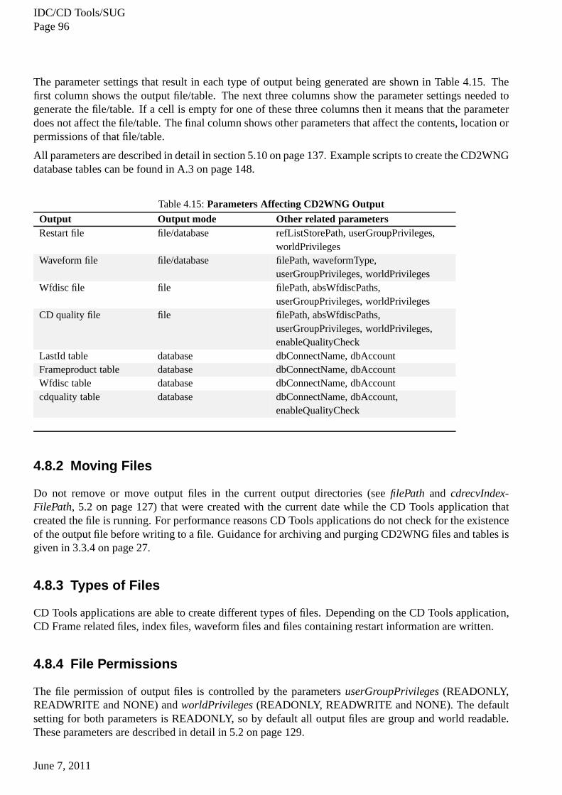
IDC/CD Tools/SUG June 7, 2011 English only! CD Tools Software User Guide This document describes how to operate the CD Tools software system. It describes the command line interface and how to start and stop the software. It logically groups configuration parameters and describes them in detail. It describes input files and output files and gives examples where necessary. It also contains suggestions for smooth daily operation of the software. Summary CD Tools is a software system that contains a number of components (or tools), which can interact with continuous seismoacoustic data from IMS stations (or from a data centre forwarding data from IMS stations). Tools are available for receiving, storing, parsing, sending and reporting. The package is designed so that each tool can be used independently, or the tools can be used together to perform a number of tasks.
Transcript
IDC/CD Tools/SUGJune 7, 2011
English only!
CD Tools Software User Guide
This document describes how to operate the CD Tools softwaresystem. It describesthe command line interface and how to start and stop the software. It logically groupsconfiguration parameters and describes them in detail. It describes input files andoutput files and gives examples where necessary. It also contains suggestions forsmooth daily operation of the software.
Summary
CD Tools is a software system that contains a number of components (or tools),which can interact with continuous seismoacoustic data from IMS stations (or froma data centre forwarding data from IMS stations). Tools are available for receiving,storing, parsing, sending and reporting. The package is designed so that each toolcan be used independently, or the tools can be used together to perform a numberof tasks.
IDC/CD Tools/SUGPage 2
Document History
Version Date Author Description
1 8 September 2004 Gerald Klinkl Initial document. Merge CD Receiver SUG and
CD Controller SUG
19 January 2006 John Coyne, Stephen Lloyd, Gerald
Klinkl, Andrew Martins
Included all functionality from cdtools-1.18 and
cd2w-1.5.2
17 March 2006 Stephen Lloyd, Gerald Klinkl Included all functionality from cdtools-2.0.4 and
cd2w-2.0.4
21 June 2006 Stephen Lloyd Included all functionality up to and including
cd2w-2.1.5
1.1 18 December 2006 Gerald Klinkl Document format changed.Included all
functionality from cdtools-2.0.17
1.2 8 February 2007 Idriz Smaili Included John’s feedback
1.3 30 March 2007 Gerald Klinkl Included all functionality up to cdtools 2.0.22
1.4 15 May 2007 Gerald Klinkl Added DB tables to index
1.5 4 September 2007 Gerald Klinkl Included all functionality from cdtools-2.1.7
1.6 10 October 2007 Gerald Klinkl Included Tim’s feedback
1.7 22 November 2007 Gerald Klinkl Included John’s feedback
1.8 27 February 2009 Gerald Klinkl Included CD2WNG and removed CD2W
1.9 3 June 2009 Gerald Klinkl Included John’s feedback, quality records and
added differences between old and new CD2W to
appendix
2.0 10 July 2009 Gerald Klinkl Included Tim’s feedback
2.1 24 July 2009 Gerald Klinkl Included more of Tim’s feedback
2.2 10 August 2009 Gerald Klinkl Added cdrep changes and
maxWfdiscMemoryDurationparameter
2.3 10 November 2009 Gerald Klinkl Added frame time length toclf file and timely
ordered sending mode
2.4 16 August 2009 Gerald Klinkl Added cdDataGen, cdFeed.pland cdCheck.pl
2.5 17 December 2009 Gerald Klinkl Added dataTimeOrder.pl
2.5 21 January 2010 Gerald Klinkl AddedsampleRateToleranceparameter
2.6 30 April 2010 Gerald Klinkl Added stream name to sensor info file
2.7 28 September 2010 Gerald Klinkl AddedenableAppIndexFile
This document applies to CD Tools version 2.2.2 (including CDW2NG, cdqual).
1.2 System Overview
CD Tools is a software system that contains a number of components (or tools), which can interact withcontinuous seismoacoustic data from IMS stations (or from any entity forwarding data in CD-1.0 or CD-1.1 format). Tools are available for receiving, storing, parsing, sending, archiving, and reporting. Thepackage is designed so that each tool can be used independently, or the tools can be used together toperform a number of tasks. The CD Tools described in this document are CD Receiver, CD Sender,CD2WNG, CD Controller and CD Report.
The primary users of the software are the International DataCentre (IDC) and International MonitoringSystem (IMS) Divisions at the Comprehensive Nuclear-Test-Ban Treaty Organization (CTBTO). In addi-tion, the software is used at National Data Centres (NDCs) and by IMS Station Operators. The softwareis available to State Signatories of the Comprehensive Nuclear-Test-Ban Treaty.
The software will continue to develop in the future. This is required in order to follow expected advancesin the formats and protocols (for example, the addition of command and control messages).
1.2.1 CD Receiver
CD Receiver is a software system that can receive and store continuous seismoacoustic data. The dataare sent from IMS stations (or from any entity forwarding data) according to the formats and protocolsdefined in [IDC02a, Format and Protocols CD-1.0] and [IDC02b, Format and Protocols CD-1.1].
The software is able to receive connection requests from data providers. If the request is valid, the soft-ware allows a connection to be established with the station.Multiple simultaneous connections can beestablished.
For each connection, the software can authenticate and store the received data. The received data arestored in binary format. A number of summary files can also be generated. The software also allowspreviously received data to be checked off-line for errors.
CD Receiver can be securely monitored and controlled using the CD Controller software.
1.2.2 CD Sender
CD Sender is a software system that can send data in CD-1.0 or CD-1.1 formats. The data to be sentare read from input files. The names of the input files indicatewhether the data are in CD-1.0 or CD-1.1
June 7, 2011
IDC/CD Tools/SUGPage 11
format. The same data may be sent to one or more destinations (data consumers). If the connection to adestination is stopped for any reason, CD Sender will attempt to re-establish the connection when thereare data to be sent. There are different options concerning the order in which data are sent to a destination.
CD Sender can be securely monitored and controlled using theCD Controller software.
1.2.3 CD2WNG
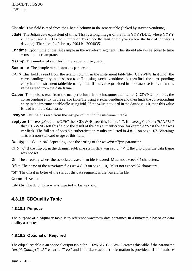
CD2WNG is a software system that reads CD-1.0 or CD-1.1 format data frames, forms continuous wave-form segments and references the waveforms in a table. This table can be stored either in a flat file or in arelational database. The continuous waveform segments formed by CD2WNG are much more amenableto data processing than raw CD frames, since reading long data segments is more efficient than readingnumerous short segments from the CD data frames. CD2WNG can also write additional information tothe database to describe the waveform data. This includes timeliness and CD data quality metrics (in thecdquality table, see 3.3.6 on page 29).
1.2.4 CD Controller
CD Controller is a software system that can send command requests to and receive command responsesfrom the CD Receiver and CD Sender. The software is able to sign each request and to authenticateeach received response. The message exchange follows the principles in [IDC02b, Formats and ProtocolsCD-1.1].
1.2.5 CD Report
CD Report is a software system that can parse index, clf and binary files created by CD Receiver or CDSender and create different views of the data.
The software allows the user to extract information about received frames or channels found in the inputdata or to detect events (connected, disconnected, channelstatus changed, ...) in the input data without theneed to write custom applications. The software is designedto be used in a tools chain as input for otherapplications or scripts (see also 3.7.11 on page 56)
1.2.6 CDqual
CDqual is a software system that measures data availability, mission capability and data quality for datafrom seismic, hydroacoustic and infrasound stations usingquality information provided by the cdqualitytable and data found in waveform files.
1.3 Document Overview
This document describes how to operate the CD Tools version 2.1.x software system.
The document describes the command line interface and how tostart and stop the software. It logicallygroups configuration parameters and describes them in detail. It describes input files and output files andgives examples where necessary. It also contains suggestions for smooth daily operation of the software.
June 7, 2011
IDC/CD Tools/SUGPage 12
Chapter “GETTING STARTED” provides a brief introduction how to start each application.
Chapter “OPERATION” provides more detailed explanation ofhow to operate and maintain each appli-cation.
Chapter “INPUT AND OUTPUT” provides a comprehensive description of all input and output entitiesfor each application.
Chapter “CONFIGURATION PARAMETERS” provides a comprehensive description of all configurationparameters for each application.
Chapter “SECURITY CONSIDERATIONS” discusses usage of public keys, private keys and certificatesby the applications.
The [IDC04b, CD Tools Overview] document provides an overview of all components of CD Tools.
The installation process is described in [IDC06b, NDC Software Installation Plan]. The software’s ex-ternal interfaces, Syslog output and internal structure are described in [IDC05a, CD Receiver SoftwareDesign Description], [IDC05b, CD Sender Software Design Description] and [IDC03b, CD2W Soft-ware Design Description]. The software requirements are described in [IDC04a, CD Receiver SoftwareRequirements Specification], [IDC03a, CD Sender Software Requirements Specification] and [IDC03c,CD2W Software Requirements Specification] .
This document is compliant with [IDC03d, Software User Guide Template] , [CTB02, Software Docu-mentation Framework] and the [CTB02, Editorial Manual].
June 7, 2011
IDC/CD Tools/SUGPage 13
2 GETTING STARTED
This is a brief description of the minimum steps that are needed to run a specific CD Tools application. Inmost cases, some configuration parameters must be specified using a configuration parameter file that theprogram can then read. Please note that all configuration parameters are case sensitive.
The comprehensive list of parameters used by each CD Tool canbe found in the index. A sample con-figuration file is included in the CD Tools distribution. These configuration files are also listed in A.2 onpage 145.
2.1 CD Receiver
To begin using CD Receiver, some configuration parameters must be modified. As a minimum, the fol-lowing parameter must be set:
filePath - the directory where the output data will be stored (see 5.2 on page 126).
Note that if you plan to use CD Sender or CD2WNG, CD Receiver must be configured to create an indexfile. The index file will be generated by setting the parametercdrecvIndexFilePath(see 5.2 on page 127)to a valid directory. An example of a configuration file with these two parameters is shown in A.2 onpage 145.
Once you have made the necessary change to the configuration file, you can run CD Receiver from thecommand line. The path to the configuration file must be passedas the first argument on the commandline. For example:
./cdrecv /path/to/configuration.file
Once this is done, CD Receiver should begin running, and willbe listening for connection or commandrequests on the default well-known port 8000. The ports from8002 to 8099 will be used as data ports. Nocommand requests will be accepted. By default, no attempt will be made to authenticate data, and all datawill be stored in the directory specified by the parameterfilePath. The default types of data files and loginformation will be written. New output data files will be generated each day that CD Receiver receivesdata. Data are ordered in the file in the sequence in which dataare received. Data files are organizedaccording to reception date to facilitate data file management. Data files will have an unlimited data sizeeach day.
While this introduction provides enough information to receive data with CD Receiver, the reader isstrongly encouraged to read and become familiar with the rest of this document, especially the sections on“Stopping Execution and Maintenance Activities” ( 3.1.3 onpage 19 and 3.1.4 on page 19).
2.2 CD Sender
To begin using CD Sender, some configuration parameters mustbe modified. As a minimum, the followingparameters must be set:
June 7, 2011
IDC/CD Tools/SUGPage 14
filePath - the directory where the output data will be stored.
cdrecvIndexFilePath - the directory containing the index files written by the CD Receiver, which willbe read by CD Sender (see 5.2 on page 127). Note that this parameter must be set when CD Receiveris started, since CD Receiver writes the index file, while CD Sender reads the index file.
dataConsumerFile - the file where the list of data consumers (destinations) is specified (see 5.8.1 onpage 134).
productionLineFile - the file where the list of stations to send to each data consumer is specified(see 5.8.1 on page 134).
refListStorePath - the directory that contains the Restart Files used by CD Sender to record whatframes have been sent to each data consumer (see 5.9.2 on page136).
The files referenced bydataConsumerFileandproductionLineFilemust be created manually before datacan be sent by CD Sender. The format of these files is describedin 4.7.5 on page 70 and 4.7.6 on page 71,respectively. An example of a configuration file is shown in A.2 on page 145.
Once the necessary changes to the configuration files have been made, CD Sender can be run from thecommand line. The path to the configuration file must be passedas the first argument on the commandline. For example:
./cdsend /path/to/configuration.file
Once this is done, CD Sender should begin running, and will look for index files written by CD Receiver.CD Sender will not be listening for command requests on the default command port 8001 in the defaultconfiguration. The index file (written by CD Receiver) lists files containing frames that can be sent byCD Sender. Data frames from the stations listed in the production line file will be sent to the specifieddestinations. As data are sent, the status of sent frames foreach station/destination pair will be periodicallywritten to the restart files. No other output files are createdby default.
While this provides an introduction of how to send data with CD Sender, the reader is strongly encouragedto read and become familiar with the rest of this document, especially the sections on “Stopping Executionand Maintenance Activities” ( 3.2.3 on page 23 and 3.2.4 on page 23). The reader should also becomefamiliar with the parameters listed above.
2.3 CD2WNG
To begin using CD2WNG, some configuration parameters must bemodified. As a minimum, the followingparameters must be set:
filePath - the directory where the output data will be stored (see 5.2 on page 126).
cdrecvIndexFilePath - the directory containing the index files written by the CD Receiver, which willbe read by CD2WNG (see 5.2 on page 127). Note that this parameter must be set when CD Receiveris started, since CD Receiver writes the index file, while CD2WNG reads the index file (see 4.8.6on page 97).
cd2wProductionLineFile - the file where the list of stations to process is specified (see 5.8.1 onpage 134).
refListStorePath - the directory that contains the Restart Files used by CD2WNG to record what frameshave been processed (see 5.9.2 on page 136).
June 7, 2011
IDC/CD Tools/SUGPage 15
An example of a configuration file with these four parameters is shown in A.2 on page 145. It is possibleto share a configuration file between CD Sender and CD2WNG, butin this case a different control portmust be configured for CD Sender and CD2WNG. It is also recommended, that none of the data consumernames used for the CD Sender instance is used as the random string in CD2WNG’s production line file.Once the necessary changes to the configuration file have beenmade, CD2WNG can be run from thecommand line. The path to the configuration file should be passed as the first argument on the commandline. For example:
./cd2wng /path/to/configuration.file
CD2WNG will then start to process each binary file listed in the CD Receiver index file. For each bi-nary file, CD2WNG will read each channel sub-frame from each valid data frame. For each sub-frame,CD2WNG will write the valid (non-duplicate) waveform data to the correct position in the waveform file.CD2WNG will then adjust the corresponding wfdisc records sothat the waveform data is indexed withthe minimum possible number of wfdisc records. When a user-specified number of data frames have beenprocessed, then CD2WNG will write the updated wfdisc records to the wfdisc file. The larger the numberof frames, the less the load on the database, but the longer the time interval between commits.
While this introduction provides enough information to process data with CD2WNG, the reader is stronglyencouraged to read and become familiar with the rest of this document, especially the sections on StoppingExecution and Maintenance Activities (see 3.3.3 on page 26 and 3.3.4 on page 27).
2.4 CD Controller
CD Controller is used to securely monitor and control CD Receiver or CD Sender. Essentially, the well-known port of the CD Receiver or the control port of the CD Sender instance must be reachable in orderto use CD Controller.
For security reasons, CD Controller will work only if a private key and a certificate, which containsthe corresponding public key, are available and if the toolsare compiled with authentication enabled. Theprivate key is used by CD Controller to sign the command requests; the certificate is used by the controlledapplication to authenticate the command request. CD Senderand CD Receiver will always behave as instrict mode with frame authentication switched on when processing a command request frame. This meansthat the connection is dropped when frames deviate from the protocol or when the signature can not beauthenticated, regardless of the current value ofstrictModeEnableandverSigEnable.
The comprehensive list of parameters used by CD Controller can be found in section 5 on page 124. Tobegin using CD Controller, some configuration parameters must be modified.
As a minimum, the following parameters must be set (see 5.6 onpage 131):
certDirectory - the directory where the certificates are stored or
ldapServer - the name of the LDAP server where the certificates are stored
privateKeyName - password and name of the file containing the private key for signing the request
privateKeyId - CD-1.1 key ID of the private key.
An example of a configuration file is shown in A.2 on page 145. Once the necessary changes to theconfiguration file have been made, CD Controller can be run from the command line. The path to theconfiguration file must be passed as the first argument on the command line. The second argument is
June 7, 2011
IDC/CD Tools/SUGPage 16
made up of the value for the frame destination field in the CD-1.1 frame header1, the IP address and theport to which the command request is sent. The third argumentis the command to be sent. For example:
Once this is done, CD Controller can be used to control an active CD Receiver or CD Sender instance.However, the controlled application must be able to authenticate the signed messages received from CDController. See 4.7.11 on page 75 for more information on theuse of private and public keys by the CDTools Applications.
CD Controller can be used to monitor or control a CD Tools application by sending a signed command re-quest frame to an active CD Receiver or CD Sender. It then waits for the command response, authenticatesthe response (if signature verification is activated), writes the command response to stdout (see Glossaryon page 157) and CD Controller stops running.
While this introduction provides enough information to send a command to an active CD Receiver or CDSender, the reader is strongly encouraged to read and becomefamiliar with the rest of this document.
2.5 CD Report
To begin using CD Report, some configuration parameters mustbe modified. As a minimum, the followingparameters must be set:
cdrecvIndexFilePath - the directory containing the index files written by the CD Receiver, which willbe read by CD Report (see 5.2 on page 127). Note that this parameter must be set when CD Receiveris started, since CD Receiver writes the index file, while CD Report only reads the index file.
An example of a configuration file is shown in A.2 on page 145. Once the necessary change to theconfiguration files have been made, CD Report can be run from the command line. The path to theconfiguration file must be passed as the first argument on the command line. For example:
./cdrep /path/to/configuration.file
Once this is done, CD Report will begin running, and will lookfor index files (for the default well-knownport) written by CD Receiver. The index file lists all files containing frames that can be processed by CDReport.
The output created by CD Report depends on the command line arguments following the path to theconfiguration file. These command line arguments are optional parameters and are used to specify anoutput mode. The following output modes are supported:
-h [timely_data_window] event log history (.ehl) file creation mode. This is the default mode if noargument is supplied.
-f frame stream mode. Writes a description about all received and virtual frames tostdout.
-c channel stream mode. Writes a description about all received channels tostdout.
-d extended channel stream mode. In addition to the output of the channel stream mode the file name andpath of the binary file and the offset of the channel from the beginning of the binary file are writtento stdout.
1For security reasons, the value of the frame creator field is also used to load the certificates used to authenticate the commandresponse.
June 7, 2011
IDC/CD Tools/SUGPage 17
-g file mode. Writes stdout stream to ehl files, the content whichwill be written to the ehl files dependson the specified stdout stream options.
The output mode options can be specified in various combinations, except the options -c and -d all otheroptions can be combined. For more detailed information see on page 39.
While this provides an introduction of how to run CD Report, the reader is strongly encouraged to readand become familiar with the rest of this document, especially the sections on “Stopping Execution andMaintenance Activities” ( 3.5.3 on page 38 and 3.5.4 on page 38). The reader should also become familiarwith the parameters listed above.
2.6 CDqual
To begin using CDqual, some configuration parameters must bemodified. As a minimum, the followingparameters must be set:
dbConnectName - the data source name used for retrieving operational data (see 5.10.3 on page 139).
dbAccount - the database account used for retrieving operational data(see 5.10.3 on page 139).
dbConnectNameArchive - the data source name used for retrieving archived data (see5.10.3 onpage 139).
dbAccountArchive - the database account used for retrieving archived data (see 5.10.3 on page 139).
An example of a configuration file is shown in A.2 on page 145. Once the necessary change to the config-uration file has been made, CDqual can be run from the command line. The path to the configuration fileand at least a station or network or station/channel combination must be passed as mandatory argumentson the command line. For example:
It is not allowed to provide only a channel name. Channel names are only valid in combination with stationor network names, e. g. WRA/BHZ. Once this is done, CDqual will begin running, and will produce achannel report for the previous day for the specified stationor network. Output will be written to stdout inthe default XML format. If CDqual is run without arguments, ashort help text is displayed which explainsthe command line options. CDqual will stop if the requested report is created.
June 7, 2011
IDC/CD Tools/SUGPage 18
3 OPERATION
This section describes how components of CD Tools can be started and stopped. It also describes mainte-nance activities, different modes of operation, and resource requirements.
The first argument is mandatory, which is the name of a configuration file. The second argument isoptional, and can be used to specify the name of an offline control file. If CD Receiver is started with oneargument, it will run in online mode and listen on the well-known port. For example:
./cdrecv ../config/config.par
If the configuration file is not specified then a usage message is displayed and CD Receiver exits withstatus -1:
If CD Receiver is started with two arguments, it will not listen on the well-known port. It will start toprocess the files specified in the offline control file instead.For example:
./cdrecv ../config/config.par offlinecontrol.txt
Stopping CD Receiver is described in 3.1.3 on the facing page. The offline control file is described in 4.7.3on page 67.
3.1.2 Automatic Invocation from a Script
As described above, it is possible to invoke CD Receiver fromthe command line and run it in the back-ground. However, in the (unlikely) event that CD Receiver stops unexpectedly, CD Receiver will not berestarted automatically. This risk of the non-availability of CD Receiver can be addressed by starting CDReceiver from the script “start_cdtool”. This same script can be used to start CD Sender, CD Reportand CD2WNG. This script starts CD Receiver, and will restartthe program if for some reason it stops.When the script successfully starts CD Receiver, a notice ofthis event is mailed to the operator specifiedin the script. More details concerning the script start_cdtool can be found in the appendix section A.1 onpage 144. To start CD Receiver automatically every time the machine is booted, an init script has to becreated. See /etc/init.d/README1 or ask your system administrator for more details of how these scriptswork.
1The README file is available on Solaris and on the most Linux distributions
June 7, 2011
IDC/CD Tools/SUGPage 19
3.1.3 Stopping Execution
CD Receiver also handles user interaction. Direct user run-time interaction with CD Receiver is limitedto CD Receiver termination. For more complex or remote user run-time interaction with CD Receiveranother tool named CD Controller is provided. Direct user run-time interaction is achieved by pressingcontrol C (ctrl-c) on the controlling terminal or sending a SIGINT signal to the CD Receiver process (kill-2 <process id>). Upon receipt of this termination request CD Receiver will begin an orderly shutdown.In this shutdown mode CD Receiver will finish handling the frames that are currently being processedbefore sending an alert frame and terminating. However, if there is no time for a graceful shutdown, arapid shutdown of CD Receiver can be requested by issuing a further control C or sending a SIGUSR1signal (kill -USR1 <process id>). This causes the immediate, but safe, shutdown of CD Receiver. CDReceiver still sends the appropriate terminating Alert Frames, closes the log files and terminates in anorderly fashion, but the processing of the current frame is abandoned.
CD Receiver will also stop execution if it detects that the file system is full. In the case of a full file system,CD Receiver will refuse to run. In the event that CD Receiver is started using the script start_cdtool, ande.g. the file system is full, an alert message is sent to the operator when the script attempts to re-startCD Receiver. The script will re-start CD Receiver beginningwith an interval of 60 seconds. In the casethat CD Receiver is terminated less than 60 seconds after it has been re-started the script will increase theinterval by doubling the time until the value of 1920 secondsis reached. This loop of restarting the CDTool will never exit, unless start_cdtool is terminated with a kill signal.
3.1.4 Maintenance Activities
Once CD Receiver is running and receiving data, certain maintenance actions are needed, otherwise allavailable disk space will be consumed.
One action concerns Syslog output. Depending on the configuration of Syslog it is important to be awarethat a significant volume of Syslog output can be generated (both in terms of local system configurationand CD Receiver configuration, see the parametersenableSyslog, 5.3 on page 129 andverSigEnable, 5.6on page 131). This is particularly true in the event of authentication failures. If the data shall be authen-ticated, it is critical that the authentication will pass successfully, or otherwise a warning message will bewritten to Syslog reporting the authentication failure foreach channel for each frame. This can total 8640messages per channel per day for 10-second Data Frames. Consequently, it is important that the localsystem administrator configures Syslog correctly for the expected volume of log entries. See [IDC03e,Using Syslog].
The second action concerns the output files generated by CD Receiver. In some cases, it will the outputfiles will be archived to another file system. There may also bea need to remove CD Receiver output filesafter a certain time period. One simple way to do this is to create a cron job, which removes all data filesthat have not been updated for some period of time. Here is an example of such a crontab entry, whichruns once per day and removes all files under the directory /dvl/cd/data that have not been modified for atleast 20 days:
## remove all files that have not been modified for at least 20 d ays#5 20 * * * find /dvl/cd/data -type f -mtime +20 -exec rm -f {}\;
Please keep in mind that output files generated by CD Receiverare used by other applications like CDSender and CD2WNG. Removing these files too early might causeserious problems for other applications.
June 7, 2011
IDC/CD Tools/SUGPage 20
For example, CD Sender will shutdown if an index file modified more recently thanlookBackTimeSched(see 5.9.2 on page 136) is moved away when it scans for new index entries.
3.1.5 Concept of Operation
In most cases one instance of CD Receiver should be sufficientfor receiving data from a number ofstations. At the IDC, several instances of CD Receiver routinely receive data from around 30 IMS stationsfor each instance.
However, there is an important limitation of the Solaris Operating System, which must be kept in mindif one is using that operating system. Under Solaris there isa maximum of 256 concurrently open filesper process when using the fopen() command (Sun Microsystems, 2002). If there are five open files perstation (bin, txt, clf, wfdisc, and socket), this would restrict the number of stations that can be received byone instance of CD Receiver to just over 40 stations.
Under the Linux Operating System this maximum of open files can be set to 64,000 instead of 1024, whichis the default value2. This means that even with five open files per station, one instance of a CD Receiverunder Linux would be restricted to 12,000 stations. So essentially there is no restriction, as other factorswould cause constraints before that limit is ever approached.
If more than one instance of CD Receiver is needed, the following points should be considered:
• Each instance of CD Receiver must use a different well-known port if run on the same machine.If there is an attempt to start more than one instance using the same well-known port, the sec-ond instance will report an error message and will fail to start (see theport parameter, see 5.1 onpage 124).
• The port range that is used for receiving data should be different for the different instances onthe same machine (see thestartPort andfinishPortparameters in 5.7 on page 134). While this isnot a strict requirement, it will simplify administration and troubleshooting. If this is not done,the possibility of running out of valid data ports may be increased, and trouble shooting will beunnecessarily complicated. Note that by default, CD Senderuses the port one more than the CDReceivers well-known port. The subsequent 98 ports which are used by default by CD Receiver, arespecified bystartPortandfinishPort.
• The different instances must not write to the same Index file(see parametercdrecvIndexFilePath, 5.2on page 127). If multiple instances write to the same Index file, there is a potential that the file maybecome corrupt. Since the well-known port is part of the index file name, this problem would onlyoccur if different instances of CD Receiver run on differentmachines, use the same well-known port(on different machines), and write to the index file in the same directory.
3.1.5.1 Operating Modes
CD Receiver can run in one of two modes: online mode or offline mode. CD Receiver operates in onlinemode if one command line argument is specified, and operates in offline mode if two command linearguments are specified.
2The command ulimit -n shows the current value, a per user limit can be set in /etc/security/limits.conf (at least in Debian)
June 7, 2011
IDC/CD Tools/SUGPage 21
Online Mode In online mode, CD Receiver listens for connection requestson the well-known port,responds to the sender if appropriate, and begins to receiveand store data.
When CD Receiver is waiting for and processing connection requests, a (previously connected) station isconsidered to be in the unconnected state. Once the data portis open a station is considered to be in theconnected state. Each data stream being received in the connected state is handled separately. This allowseach connection to be handled distinctly from other connections. This minimizes the influence that oneconnection can have on CD Receiver.
All received frames are checked for errors. There are some parameters (see error checking options 5.5 onpage 130) that can influence what checks are made, the consequences of certain errors (e.g. warning orfatal), and what data files are stored on disk. Details concerning the types of checks that are made can befound in the [IDC05a, CD Receiver Software Design Description].
Offline Mode Offline error checking is specified via a second command line argument, the offlinecontrol file. Data in the files specified in the offline control file are treated in the same manner as datareceived from a station in connected state. Depending on theconfiguration, binary, text, frame summaryand wfdisc files are created for the checked data in the configured directory (see also 5.2 on page 126).All files created in offline mode have an extra “_off” extension appended to their suffixes. Please notethat only data received in the connected state can be checkedin offline mode. A station is considered tobe in the connected state once the data port is open and Data Frames are being received. Data sent tothe well-known port are not checked in offline mode. Please also note that CD Receiver is not able todistinguish between received and sent frames in the file. If the file being checked contains data sent byCD Receiver3, CD Receiver will treat these data in offline mode in the same way as received data.
3.1.5.2 Receiving forwarded CD-1.1 data
Receiving forwarded CD-1.1 requires some additional configuration. This is caused by the fact that framesfor connection establishment and frames for connection handling do not have the original frame creatorname in the frame header when the data is forwarded. Even dataframes might have a different framecreator name if a channel filter has been applied. For security reasons, a frame created by a CD Senderforwarding data from the original station will not pass the frame signature check when the forwarding CDSender has not been configured to be allowed to sign frames on behalf of the original station (see also 4.7.4on page 68). Please note that a CD Sender which forwards data is never allowed to re-sign channel data!
3If logOutgoingDatais set to YES then all outgoing data (e.g. connection response, alert frames, etc.) will be saved in thesame file(s) as incoming data. If it is set to NO then no outgoing data is saved.
June 7, 2011
IDC/CD Tools/SUGPage 22
Figure 3.1:Receiving forwarded Data
3.1.6 Station Upgrades
A station upgrade from CD-1.0 to CD-1.1 protocol requires nomanual intervention if the station stopssending data for more than one minute between the protocol change.
3.1.7 Resource Usage
The CPU and memory usage requirements are minimal for the tasks of receiving and storing the data.However, the CPU requirements for authentication are significant. For example, authenticating 30 chan-nels of data for one day requires about 40 minutes of CPU usingan Ultra-sparc 400 MHz chip.
The first argument is mandatory, which is the name of a configuration file. The second and the thirdarguments are optional and can be used to specify a start and end time. For example:
./cdsend config.par
starts CD Sender in continuous mode and it will consider all clf files less thanlookBackTimeSchedold(see 5.9.2 on page 136). If the configuration file is not specified then a usage message is displayed andCD Sender exits with status -1:
If CD Sender is started with two arguments, it will run in fixedinterval mode, and instead of using thevalue of lookBackTimeSched, it will use the second argument to find which clf files are newer than thespecified time but no more recent than the time at which CD Sender was started. For example:
./cdsend config.par ’2004/01/01 00:00:00’
If CD Sender is started with three arguments, it will run in fixed interval mode, consider all clf files lessthan the second argument old, but not more recent than the third argument. For example:
As described above, it is possible to invoke CD Sender from the command line and run it in the back-ground. However, in the (unlikely) event that CD Sender stops unexpectedly, or the machine is rebooted,CD Sender will not be restarted automatically. See 3.1.2 on page 18 for more information on re-startingCD Sender from a script.
3.2.3 Stopping Execution
CD Sender also handles user interaction. Direct user run-time interaction with CD Sender is limited toCD Sender termination. For more complex or remote user run-time interaction with CD Sender anothertool named CD Controller is provided. Direct user run-time interaction is achieved by pressing controlC (ctrl-c) on the controlling terminal or sending a SIGINT signal to the CD Sender process (kill -INT<process id>). Upon receipt of this termination request CD Sender will begin an orderly shutdown. In thisshutdown mode CD Sender will finish sending the frames that are currently being sent before terminating.However, if there is no time for a graceful shutdown, a rapid shutdown of CD Sender can be requestedby issuing a further control C or sending a SIGUSR1 signal (kill -USR1 <process id>). This causes theimmediate, but safe, shutdown of CD Sender. CD Sender closesthe log files and terminates in an orderlyfashion, but the sending of the current frame is abandoned.
CD Sender will also stop execution if it detects that the file system is full. In the case of a full file system,CD Sender will refuse to run.
3.2.4 Maintenance Activities
No maintenance actions are needed when running CD Sender in the default configuration, but keep inmind that CD Sender generates Syslog entries when a warning or an error occurs. Consequently, it isimportant that the local system administrator configures Syslog correctly for the expected volume of logentries. See [IDC03e, Using Syslog].
3.2.5 Concept of Operation
CD Sender is used to send CD frames. CD Receiver writes the frames that will be sent. Only Dataor Data Format Frames are taken from binary input files to be sent. Control frames like Alert Framesare generated by CD Sender itself. CD Sender will send all Data or Data Format Frames found in theinput file, regardless of the fact that the Frames have been received with or without an error or warning.
June 7, 2011
IDC/CD Tools/SUGPage 24
To avoid problems on the receiving side, especially when sending frames that are incomplete due to thefact that the connection has timed out before the complete frame was received, CD Sender disconnectsafter sending incomplete frames (Not implemented yet). When CD Sender is used, there is typically aone-to-one relation between the instances of CD Receiver and CD Sender. In the simplest case there isone instance of each. In order to keep things simple, the recommendation is to maintain the one-to-onerelationship between CD Receiver and CD Sender. However, itis possible to configure more than one CDSender to send frames that are received by one instance of CD Receiver. Since CD Sender uses the portand index file path of CD Receiver, one CD Sender instance can only send frames written by one instanceof CD Receiver. So while there can be a one-to-many relationship between CD Receiver to CD Sender,there can only be a one-to-one relationship between CD Sender and CD Receiver.
There may be cases where more than one instance of CD Sender isneeded. In such cases, each instanceof CD Sender must use a different control port if run on the same machine. If there is an attempt to startmore than one instance using the same control port, the second instance will report an error message andwill fail to start (seeappControlPort, 5.1 on page 125).
By default, CD Sender will be listening for command requestson the well-known port + 1 of the relatedCD Receiver. When CD Sender starts up it will check for each production line (see 4.7.6 on page 71) ifa restart file exists. A restart file contains information about which frame was the last frame sent on thatproduction line (see also 4.8.10 on page 105). If no restart file is found for a production line then CDSender will start to (re)send all frames found in the index file which were created on the current day.
If a restart file is found for a production line then CD Sender goes backlookBackTimeSchedhours(see 5.9.2 on page 136) and tries to find the last frame sent. Ifthe last frame sent is found then CDSender starts sending with the next unsent frame. If the lastframe sent can’t be found (because thelook-BackTimeSchedis too short) then CD Sender (re)sends all frames found in index files newer than thecurrent time minuslookBackTimeSched. Please keep in mind that the creation date of index files is deter-mined by its name, not by its file attribute “creation time”. Creation and update intervals of restart files arecontrolled by therefListStoreInterval(see 5.9.2 on page 136) andrefListStorePath(see 5.9.2 on page 136)configuration parameters. One case where data can be lost between a sender and receiver using the CDprotocol is when the connection is closed. During this process, data in the TCP buffer may be lost. CDSender is designed to address this issue by re-sending at least the last 10 frames after a connection is re-established. While this may result in some duplicate framesbeing sent, it greatly reduces the probabilitythat frames are lost when the connection is closed and re-established.
CD Sender sends data and data format frames regardless of whether the frames have been marked asreceived with a warning or an error or not. To prevent an infinite number of re-send attempts in casethe peer receiving software closes the connection immediately after receiving a bad frame, the maximumnumber of re-send attempts for a particular frame is limitedto three.
CD Sender can also encounter the Solaris limitation concerning the maximum number of open file de-scriptors, as explained in 3.1.5 on page 20. Depending on thetypes of output files written by CD Sender,this can limit the number of stations/destination pairs that can be handled by one instance of CD Sender(about 40 stations per instance, depending on the configuration). In such cases multiple instances of CDSender should be used to send frames from one instance of CD Receiver.
3.2.6 Operating Modes
CD Sender supports two different modes of operation: Continuous Mode and Fixed Interval Mode.
June 7, 2011
IDC/CD Tools/SUGPage 25
Continuous Mode
When CD Sender starts in continuous mode, it reads all the CD Receiver index files (see 4.8.6 on page 97)for the lastlookBackTimeSchedhours (see 5.9.2 on page 136), tries to find the frames where ithas stoppedsending (if it has been restarted) and starts sending data for each production line. When CD Sender hasparsed all the binary files listed in the index files, then it sleeps forsleepTimeSchedseconds (see 5.9.1 onpage 135). It then parses the current day’s index file again (to check for newly arrived data). This cyclecontinues until CD Sender is stopped by user request or a fatal error occurs.
Fixed Interval Mode
In fixed interval mode CD Sender looks for index files between agiven start and end time. CD Senderparses the binary files listed in these index files. CD Sender will send only data frames with nominaltime between a given start and end time and only frames that are available when the sender starts. Aftercompleting this task, CD Sender will stop automatically.
3.2.6.1 Passive Data Forwarding
CD Sender can be configured to start sending data automatically to specified data consumers for all stationsfound in the index file. In contrast to active data forwarding, where a production line must be specified foreach data provider/data consumer pair (see 4.7.6 on page 71), only one production line with a wildcard(asterisk) as data provider has to be specified.
3.2.7 Sending Order
CD Senders current sending order is determined by the configuration parameterprocessMode.For adetailed description of the CD Senders process modes see 5.8.2 on page 135.
3.2.8 Station Upgrades
A station upgrade from CD-1.0 to CD-1.1 protocol requires manual intervention. CD Sender is not de-signed to deal with data frames of different types over the same connection. To prevent a condition whereCD Sender will try to send data frames of different types overthe same connection, ensure that none of theaffected production lines are backfilling or are disconnected. The easiest way to achieve this is to check,for each affected production line, if the last frame received from the station which should be upgraded issent (check for disconnect) and check that no more than the expected frame rate (one frame every ten ortwenty) is sent in asleepTimeWorkinterval (which would indicate backfilling).
If the station stops sending data during the change of protocol, disable receiving of data from this stationto make sure that no new frames arrive before CD Sender’s restart files are modified. This can be doneeither by modifying CD Receiver’s station file and sending a “reload station file” command or by stoppingthe station with a “stop” command.
The next step is to modify the restart files of the affected production lines to make sure that no data framesare sent using the old protocol. CD Sender will normally re-send the last ten frames sent before disconnect
June 7, 2011
IDC/CD Tools/SUGPage 26
to make sure that no frames have been lost in the disconnect process. To prevent this, remove all exceptthe first two lines in the restart files of the affected production lines.4
When all production lines are modified, re-enable data reception of the upgraded station. Once datareception is re-enabled, restart CD Sender.
3.2.9 Resource Usage
The CPU and memory usage requirements are minimal for the tasks of sending frames when CD Senderis in steady state. Depending on the number of data consumers, CPU and memory usage might becomevery high if CD Sender has to backfill several days worth of data (1- 2Mb memory usage per day andproduction line, depending an the frame rate).
3.3 CD2WNG
3.3.1 Command Line Interface
CD2WNG must be started with a single command-line argument specifying the path of the configurationfile:
./cd2wng ./config.par
If the configuration file is not specified then a usage message is displayed and CD2WNG exits with status-1:
As described above, it is possible to invoke CD2WNG from the command line and run it in the back-ground. However, in the (unlikely) event that CD2WNG stops unexpectedly, or the machine is rebooted,CD2WNG will not be restarted automatically. See 3.1.2 on page 18 for more information about startingCD2WNG from a script.
3.3.3 Stopping Execution
Direct user run-time interaction with CD2WNG is limited to CD2WNG termination. Direct user run-timeinteraction is achieved by pressing control C (ctrl-c) on the controlling terminal or sending a SIGINT sig-nal to the CD2WNG process (kill -INT <process id>). Upon receipt of this termination request CD2WNGwill begin an orderly shutdown. In this shutdown mode CD2WNGwill finish processing the current dataframe, commit any outstanding changes to file/table and thenexit:
4CD Senders prior to version 2.0.18 must be manually sent a “stop” command for each production line as they do not updatetheir restart files if a connection is terminated
June 7, 2011
IDC/CD Tools/SUGPage 27
Signal 2 caught.CD2WNG stopped at 11/24/04 14:14 by signal 2.
However, if there is no time for a graceful shutdown, a rapid shutdown of CD2WNG can be requestedby issuing a further control C or sending a SIGUSR1 signal (kill -USR1 <process id>). This causes theimmediate, but safe, shutdown of CD2WNG. CD2WNG still closes the log files and terminates in anorderly fashion, but the processing of the current data frame is abandoned.
CD2WNG will also stop execution if it detects that the file system is full. In the case of a full file system,CD2WNG will refuse to run.
3.3.4 Maintenance Activities
Once CD2WNG is running and processing data, certain maintenance actions are needed, otherwise allavailable disk space will be consumed.
One action concerns Syslog output. Depending on the configuration of Syslog (both in terms of localsystem configuration and CD2WNG configuration (see the parameterenableSyslog, 5.3 on page 129), itis important to be aware that a significant volume of Syslog output can be generated. Therefore, it isimportant that the local system administrator configures Syslog correctly for the expected volume of logentries. See [IDC03e, Using Syslog].
Another action concerns the output files generated by CD2WNG. In some cases, it the output files will bearchived to another file system. There may also be a need to remove CD2WNG output files after a certaintime period. One simple way to do this is to create a cron job that removes all data files that have not beenupdated for some period of time. An example of such a crontab entry is shown in 3.1.4 on page 19.
The restart, wfdisc, cdquality and waveform files should notbe purged or archived until they are obsolete.A restart file is obsolete if it is associated with a day older than lookBackTimeSchedhours (see 5.9.2 onpage 136). If a non-obsolete restart file is deleted then restart information may be lost (see 4.8.10 onpage 105). A wfdisc, cdquality or waveform file is obsolete ifthe nominal time (data time) of its newestdata is older than most recent data - 7 days)5. CD2WNG needs to be able to update all non-obsolete wfdiscand waveform files. If these files are unavailable then this will cause CD2WNG to shut down with a fatalerror.
If CD2WNG writes to the database, it is important to purge or archive the data in order to prevent thedatabase tables and indexes from becoming too large. The database tables are described in detail insection 4.8 on page 92. If CD2WNG writes to the database, thanit also uses the lastid table in thedatabase.
The associated parameters are described in 5.10.3 on page 138.
Rows from the frameproduct table may be purged or archived ifthey are older than the current day. Rowsfrom the wfdisc and cdquality table should only be purged or archived if they are obsolete (see above).
CD2WNG needs to be able to update all non-obsolete rows from the wfdisc and cdquality table. If theserows are unavailable then this will trigger a fatal error.
5This is true only in steady state. If CD2WNG starts up themaxWfdiscMemoryDurationparameter is used to compute theinitial start time of the merging window.
June 7, 2011
IDC/CD Tools/SUGPage 28
Table 3.1:Minimum purge frequency of tables/files
Name of Table/File Purgelastid, sensor, instrument, channame Neverrestart file older thanlookBackTimeSchedwfdisc, cdquality and waveform older than most recent data processed - 7 daysframeproduct older than the current day
3.3.5 Concept of Operation
In most cases one instance of CD2WNG should be sufficient for processing data from a number of stations.At the PTS, one instance of CD2WNG is routinely used to process data from 40 IMS stations. However,under Solaris, CD2WNG may be limited by the number of concurrently open files (the limit under Linuxis much more higher). This limitation is described in 3.1.5 on page 20.
There may be cases where more than one instance of CD2WNG is needed. In such cases, the followingpoints should be considered.
• Each CD2WNG instance must have its own configuration file that specifies a command port (seeparameterappControlPort, 5.1 on page 125)
• Each CD2WNG instance should normally read from a differentindex file. See parameterscdrecvIn-dexFilePath( 5.2 on page 127) andport ( 5.1 on page 124).
• If two different CD2WNG instances read from the same index file then each instance should write toseparate output files/tables. See parametersrefListStorePath(see 5.9.2 on page 136), filePath( 5.2on page 126) anddbConnectName, dbAccount( 5.10.3 on page 138).
3.3.5.1 Operating Modes
CD2WNG can run in one of two operating modes: continuous modeor fixed-interval mode.
When CD2WNG starts in continuous mode, it reads all the CD Receiver index files (see 4.8.6 on page 97)and the restart information (see 4.8.10 on page 105) for the last lookBackTimeSchedhours (see 5.9.2 onpage 136). Each index file contains a list of binary files. CD2WNG processes the binary files in the orderin which they appear in the index file. For each binary file in the list, CD2WNG uses the restart informationto find out if it has processed the file before. The restart information is very important because it preventsCD2WNG from processing the same data twice. Regardless of how often CD2WNG is started and stoppedin continuous mode, CD2WNG will always continue from the last data processed. It is not possible toforce CD2WNG to reprocess data without manually editing therestart file (see A.4 on page 149).
When a frame is being processed, CD2WNG checks if the nominaltime of the frame is more recentthan the start time of the merging window. The initial start time of the merging windows is computedascurrent time−maxW f discMemoryDuration. All data older the start time of the merging window istreated as obsolete.
When CD2WNG has parsed all the binary files listed in the indexfiles, it then sleeps forsleepTimeSchedseconds (see 5.9.1 on page 135). It then checks if the currentbinary file has grown since the last check(to check for newly arrived data). This cycle continues until CD2WNG is killed by an external signalor a fatal error occurs. CD2WNG writes summary reports to Syslog (see 4.8.20.6 on page 122) everysummaryRefreshTimeseconds (see 5.3 on page 130).
June 7, 2011
IDC/CD Tools/SUGPage 29
In fixed interval mode CD2WNG looks for index files dated between the provided start and end time.CD2WNG parses the binary files listed in these index files and processes data with a data time betweenstart time and end time inclusive. CD2WNG then terminates. As with continuous mode, CD2WNG usesthe restart files to find out if it has processed each file before. If CD2WNG has processed the file beforethen it only processes the file from the last offset reached. If CD2WNG has not processed the file beforethen it processes the binary file from the first byte.
In fixed interval mode, start time and end time are specified onthe command line:
CD2WNG can run in one of two output modes: file mode or databasemode (see thedbConnectName,dbAccount( 5.10.3 on page 138). In both modes CD2WNG reads from the configuration file and createswaveform files. In file mode, CD2WNG also reads channel details from file (if configured, see 4.7.15on page 84) and writes wfdisc and optional cdquality recordsto file. Files are kept consistent by writ-ing all output in a transaction like manner; update waveformfile, wfdisc and cdquality files and restartinformation. CDquality files are only created if requested (see 5.10.1 on page 137).
In database mode CD2WNG reads channel details from the database and writes wfdisc and cdqualityrecords to database tables. In database mode, CD2WNG will also write frameproduct records. Theserecords can be used by other applications, or for manual analysis. Frameproduct records describe each fileparsed by CD2WNG. CDquality records are only created if requested (see 5.10.1 on page 137).
CD2WNG connects to the database using Open Database Connectivity (ODBC). Therefore an ODBCdriver and ODBC compliant database must be installed beforethis mode can be used. A number of tablesmust also be created (see A.3 on page 148). The database requirements are described in detail in [IDC06b,NDC Software Installation Plan].
The database is kept consistent by performing all the inserts and updates within the same database transac-tion. If a database operation on any table fails, then changes to all tables are rolled back to the last commitand CD2WNG exits with a fatal error. The errors reported by ODBC are minimal but CD2WNG reportsthe entire SQL command which failed to allow the error to be investigated.
The different files and tables are described in section 4.7 onpage 64 and section 4.8 on page 92. Therelated configuration parameters are described in section 5.10 on page 137.
3.3.6 Data Processing
The primary purpose of CD2WNG is to parse the binary frame files written by CD Receiver, write the datato waveform files and reference the data using wfdisc records(known as “wfdiscs”). CD2WNG writes thewfdiscs to file or database depending on the output mode.
Each wfdisc record references a single continuous waveformsegment. These waveform segments aremuch more amenable to subsequent data processing (by other applications) than raw CD frames. Thisis because reading long data segments is more efficient than reading numerous short segments from theCD data frames. Therefore CD2WNG aims to maximise the lengthof these waveform segments (up to 4hours) and thus minimise the number of wfdisc records.
June 7, 2011
IDC/CD Tools/SUGPage 30
CD2WNG parses each binary file listed in the CD Receiver indexfile. These files contain frames in CD-1.0or CD-1.1 format. Each data frame contains waveform data forone or more channels. For each channel,CD2WNG extracts the waveform data and attempts to merge thissegment with an existing waveformsegment. The new waveform segment can only be merged with an existing segment if the followingconditions are met:
• Both segments are associated with the same station, site and channel.
• Both segments are associated with the same waveform file.
• Both segments are associated with the same wfdisc file (file mode only).
• There is no unacceptable gap between the two waveform segments (see A.4 on page 148).
• There is no unacceptable overlap between the two waveform segments (see A.4 on page 148).
• Both segments have compatible sample rates (see A.4 on page148).
• Both segments have the same clipped data status (this is stored in the clip field of the wfdisc).
•
If the new waveform segment cannot be merged with an existingsegment then CD2WNG creates a newwfdisc to describe the segment. In addition, CD2WNG has special rules for obsolete data and duplicatedata. Data is defined as obsolete if it has a data time older than themostrecentdata−7days6. CD2WNGalways ignores obsolete data. Data is defined as duplicate ifit has a complete overlap with existing data.CD2WNG remembers the duplicate frame in the statistics and skips the duplicate data.
CD2WNG is also able to create cdquality records. CD quality information is an optional output forCD2WNG (see 5.10.1 on page 137). For creation of cdquality records, a second pass after merging ofwfdiscs is added. In this second pass the data of the new waveform segment is
• scanned for sensor noise and constant data,
• the running sum of the counts, the running sum of the square of the difference between the countsand the mean value (needed to calculate RMS) are calculated,
• the authentication state of the data the is checked (if requested, see 5.6 on page 131)and
• the timeliness of the data is checked
The new waveform segment can only be merged with an existing cdquality record if the following condi-tions are met:
• Both segments are associated with the same station, site and channel.
• Both segments are associated with the same waveform file.
• Both segments are associated with the same CDquality file (file mode only).
• There is no unacceptable gap between the two waveform segments.
• There is no unacceptable overlap between the two waveform segments.
• Both segments have compatible sample rates.
• The quality flags (indication sensor noise and constant data) of adjacent intervals are the same
• The authentication flags of adjacent intervals are the same
• The considered channel status bits are the same (see 5.10.1)
6This is true only in steady state. If CD2WNG starts up themaxWfdiscMemoryDurationparameter is used to compute theinitial start time of the merging window.
June 7, 2011
IDC/CD Tools/SUGPage 31
• The timely flags of adjacent intervals are the same
• The sum of the square of the differences to the mean does not exceed the value range of the C datatype used to store the sum.
If the new waveform segment cannot be merged with an existingsegment then CD2WNG creates a newcdquality record to describe the segment.
Constant data and sensor noise processing shall not be performed for some channels, such as those whichrecord meteorological conditions or state of health information (e. g. battery level). CD2WNG uses thesample rate to decide whether or not a channel should be skipped. The configuration parameterminDet-SampRateis used to set the minimum sample rate for data quality calculations (see 5.10.1 on page 138).
Other channels are not authenticated, so the authentication check is not needed in those cases. To omitthe authentication check the same approach taken for CD Receiver and CD Sender is used. That means, aNONE directive has to be created in the Key Preload File for that station, site or channel as described in[IDC06a, CD Tools Software User Guide].
3.3.6.1 Timeliness of Data
Timeliness is calculated on a per frame and channel basis as
Timely data are those which have arrived before timeliness threshold seconds have passed. Data whichare not timely are those which arrive after the timeliness threshold has passed.
3.3.6.2 Constant Data and Sensor Noise
The “constant data” flag is set if at least five consecutive samples of the waveform are of the same value.The “sensor noise” flag is set if the absolute difference between the highest and the lowest value off allsamples of the waveform is lower than 5 counts. If both conditions are full-filled, than “sensor noise” and“constant data” are set.
In addition, CD2WNG has special rules for obsolete data and duplicate data. Data is defined as obsolete ifit has a data time older than the most recent frame time processed so far minus7 days. CD2WNG ignoresobsolete data.
Data is defined as duplicate if it has an unacceptable overlapwith existing data. CD2WNG ignores theduplicate data.
June 7, 2011
IDC/CD Tools/SUGPage 32
3.3.7 Resource Usage
CD2WNG uses approximately 60 minutes of CPU time and 50 Mbytes of memory to process approxi-mately 30 stations, for a 24 hour period, with default settings using a Sun Enterprise 5500.
3.4 CD Controller
3.4.1 Command Line Interface
CD Controller requires three mandatory arguments. The firstargument is the name of a configuration file.The second argument contains the value for the frame destination field in the CD-1.1 frame header, theIP address and the port number, where the command should be sent. Destination field, IP address andport are separated by colons. The third argument is the command itself. For example use the followingcommand to request statistical information in short form from a CD application running on the local hostlistening to port 8000. The string CDTEST is used in the destination field of the frame header:
./cdcon ../config/config.par CDTEST::8000 GST
If the second argument contains an IP address, it will not connect to the specified port of the local host.Instead it will try to connect to the specified port at the specified IP address. For example use the followingcommand to request statistical information in short form from a CD application running on a remote hostwith IP address 192.168.0.2, listening on port 8000:
./cdcon ../config/config.par CDTEST:192.168.0.2:8000 G ST
3.4.2 Commands
CD Controller can control an instance of CD Receiver or CD Sender locally or remotely. Commandssupported by the CD Controller are grouped into categories:
• Commands to request statistical data
• Debugging commands
• Commands for connection management
• Commands for station management
The generic format of a command is:
command code[=parameter1[,parameter2]]
Command codes are built using a three capital character mnemonic.
A positive command response string starts with “000 OK” or “001 OK command queued” and is followedby a response text if it is a single line response. Positive multi-line responses also start with “000 OK”,but in these cases the response text begins on a new line. All command response lines are terminated by anew line character. A negative command response text is marked with a three-digit error code greater thanor equal to 100 and includes an error message.
Each command is assigned to a security level. Currently CD Tools support three different security levels:LOW, MEDIUM and HIGH. The security levels are implemented as stacked levels (this means a userhaving the right to access the security level HIGH also has the right to access the lower security levels).
June 7, 2011
IDC/CD Tools/SUGPage 33
Not all commands are executed immediately in the controlledapplication. Therefore responses to somecommands will be “001 OK command queued”. In such cases another command can be sent to verify thatthe command was executed as expected.
The command response text returned to CD Controller is not intended to be read directly by humans andin most cases consists only of numbers. To transform these numbers into human readable text a wrapperfor CD controller named cdcon.pl is also provided in the CD Tools distribution. See 3.7.5 on page 52 formode details on cdcon.pl.
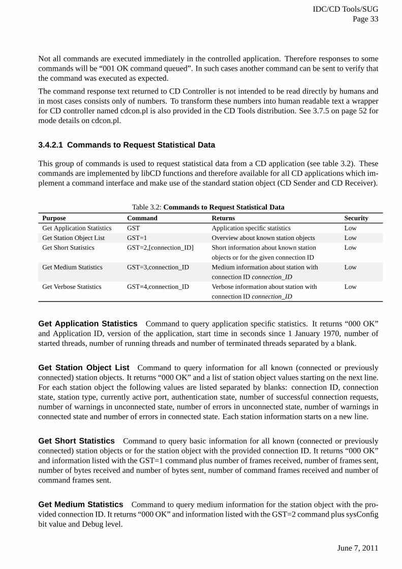
3.4.2.1 Commands to Request Statistical Data
This group of commands is used to request statistical data from a CD application (see table 3.2). Thesecommands are implemented by libCD functions and therefore available for all CD applications which im-plement a command interface and make use of the standard station object (CD Sender and CD Receiver).
Table 3.2:Commands to Request Statistical Data
Purpose Command Returns Security
Get Application Statistics GST Application specific statistics Low
Get Station Object List GST=1 Overview about known station objects Low
Get Short Statistics GST=2,[connection_ID] Short information about known station
objects or for the given connection ID
Low
Get Medium Statistics GST=3,connection_ID Medium information about station with
connection IDconnection_ID
Low
Get Verbose Statistics GST=4,connection_ID Verbose information about station with
connection IDconnection_ID
Low
Get Application Statistics Command to query application specific statistics. It returns “000 OK”and Application ID, version of the application, start time in seconds since 1 January 1970, number ofstarted threads, number of running threads and number of terminated threads separated by a blank.
Get Station Object List Command to query information for all known (connected or previouslyconnected) station objects. It returns “000 OK” and a list ofstation object values starting on the next line.For each station object the following values are listed separated by blanks: connection ID, connectionstate, station type, currently active port, authentication state, number of successful connection requests,number of warnings in unconnected state, number of errors inunconnected state, number of warnings inconnected state and number of errors in connected state. Each station information starts on a new line.
Get Short Statistics Command to query basic information for all known (connectedor previouslyconnected) station objects or for the station object with the provided connection ID. It returns “000 OK”and information listed with the GST=1 command plus number offrames received, number of frames sent,number of bytes received and number of bytes sent, number of command frames received and number ofcommand frames sent.
Get Medium Statistics Command to query medium information for the station object with the pro-vided connection ID. It returns “000 OK” and information listed with the GST=2 command plus sysConfigbit value and Debug level.
June 7, 2011
IDC/CD Tools/SUGPage 34
Get Verbose Statistics Command to query information for the station object with theprovided con-nection ID. It returns “000 OK” and information listed with the GST=3 command plus the followingvalues: number of connection requests when the station was already connected (provided only by CDReceiver, otherwise zero), number of connection or commandrequests from an unauthorized station (onlythe unconnected station object), number of connection requests from an unauthorized IP address (only theunconnected station object), number of authentication failures, number of invalid frames received, num-ber of connection requests timed out, number of unexpected closed connections and number of systemfailures. The first value has no meaning in connected state and is therefore always zero.
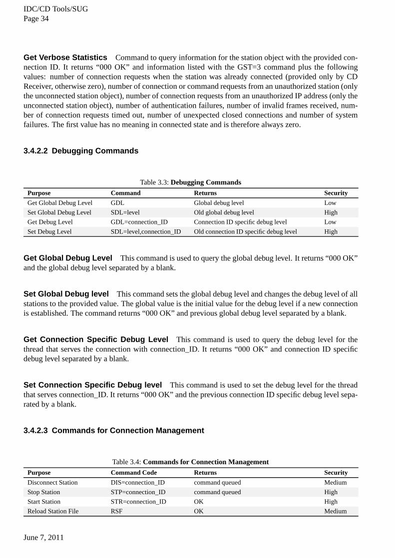
3.4.2.2 Debugging Commands
Table 3.3:Debugging Commands
Purpose Command Returns Security
Get Global Debug Level GDL Global debug level Low
Set Global Debug Level SDL=level Old global debug level High
Get Debug Level GDL=connection_ID Connection ID specific debug level Low
Set Debug Level SDL=level,connection_ID Old connection ID specific debug level High
Get Global Debug Level This command is used to query the global debug level. It returns “000 OK”and the global debug level separated by a blank.
Set Global Debug level This command sets the global debug level and changes the debug level of allstations to the provided value. The global value is the initial value for the debug level if a new connectionis established. The command returns “000 OK” and previous global debug level separated by a blank.
Get Connection Specific Debug Level This command is used to query the debug level for thethread that serves the connection with connection_ID. It returns “000 OK” and connection ID specificdebug level separated by a blank.
Set Connection Specific Debug level This command is used to set the debug level for the threadthat serves connection_ID. It returns “000 OK” and the previous connection ID specific debug level sepa-rated by a blank.
3.4.2.3 Commands for Connection Management
Table 3.4:Commands for Connection Management
Purpose Command Code Returns Security
Disconnect Station DIS=connection_ID command queued Medium
Stop Station STP=connection_ID command queued High
Start Station STR=connection_ID OK High
Reload Station File RSF OK Medium
June 7, 2011
IDC/CD Tools/SUGPage 35
Disconnect Station Command to signal the thread that serves connection_ID to close the connection.It returns “001 OK command queued” or an error message if the connection ID is unknown.
Stop Station Signals the thread that serves connection_ID to close the connection and set the stationin the stopped state. No connection request is accepted or noattempt to establish a connection to senddata is made in this state. It returns “001 OK command queued”or an error message if connection ID isunknown. This is the inverse of the “Start Station” command.
Start Station Enables processing of connection requests from station connection_ID or enables send-ing of data for the production line which serves connection_ID. It returns “000 OK” or an error messageif connection ID is unknown. This is the inverse of the “Stop Station” command.
Reload station file Forces a reload of the configured station file (if any). The station file is specifiedwith the configuration parameterstationFile (see 5.1 on page 126). This command has no impact onalready established connections. It returns “000 OK”.
3.4.2.4 Commands for Station Management
Table 3.5:Commands for Station Management
Purpose Command Returns Security
Get Global Configuration
Parameter
GCP global configuration value Low
Set Global Configuration
Parameter
SCP=bitvalue Old global configuration value High
Get Configuration
Parameter
GCP=connection_ID Connection ID specific configuration value Low
Set Configuration ParameterSCP=bitvalue,connection_IDOld connection ID specific configuration
value
High
Get Global Configuration Parameter This command is used to query the global configuration pa-rameters. It returns “000 OK” and the global system configuration value separated by a blank. Thereturned value is the sum of the systemConf tags defined in “include/CDtools/cd_common.h” in the gbase-libs distribution. To transform this number into human readable text the explain CD helper application(see 3.7.6 on page 53) is provided in the CD Tools distribution.
Set Global Configuration Parameter This command sets the global configuration parameter tobitvalue. All station specific configuration values are set to the global value and when a new connectionsis established, it will also get this value. The value of bitvalue is the sum of the bit values for the requestedsystemConf tags defined in “include/CDtools/cd_common.h”in the gbase-libs distribution. The commandreturns “000 OK” and old global system configuration value separated by a blank.
Get Connection ID Specific Configuration Parameter This command is used to query the con-figuration parameter for the thread that serves connection_ID. It returns “000 OK” and the connection IDspecific value separated by a blank.
June 7, 2011
IDC/CD Tools/SUGPage 36
Set Connection Specific Configuration Parameter This command sets the configuration param-eter for the thread that serves Connection_ID to the given bitvalue. The value of bitvalue is the sum ofthe bit values for the requested systemConf tags defined in “libsrc/libcd/cd_common.h” in the gbase-libsdistribution. The command returns “000 OK” and old global system configuration value separated by ablank.
3.4.3 Command Response Text Transformation
As mentioned above, the command response text received by CDController is not intended to be readdirectly by humans. To transform the response text into a more human-friendly form, a wrapper for CDcontroller named cdcon.pl is provided in the CD Tools distribution (see 3.7.5 on page 52).
3.4.4 Automatic Invocation from a Script
As described above, it is possible to invoke CD Controller from the command line and run it in thebackground. However, in most of the cases, CD controller will be started by a script. See 3.7.5 on page 52for more information about starting CD Controller from a CD Helper Application.
3.4.5 Stopping Execution
CD Controller also handles user interaction. Currently user run-time interaction with CD Controller islimited to CD Controller termination. This is achieved withpressing control C (ctrl-c) on the controllingterminal or sending a SIGINT signal to CD Controller process(kill -INT <process id>). Upon receiptof this termination request CD Controller will begin an orderly termination. However, sending signals toCD Controller is typically not needed, as CD Controller is a short-lived process, and terminates after itreceives and prints the response that was received.
3.4.6 Maintenance Activities
No maintenance actions are needed when running CD Controller, but keep in mind that CD Controllergenerates Syslog entries when a warning or an error occurs. Consequently, it is important that the localsystem administrator configures Syslog correctly for the expected volume of log entries. See [IDC03e,Using Syslog].
3.4.7 Concept of Operation
3.4.7.1 Operating Modes
CD Controller can run only in online mode.
3.4.8 Resource Usage
The CPU and memory usage requirements are negligible for thetasks of sending and receiving controlframes.
June 7, 2011
IDC/CD Tools/SUGPage 37
3.5 CD Report
3.5.1 Command Line Interface
CD Report accepts the following command line arguments.
The first one is a mandatory argument, which is the name of a configuration file. The other arguments areoptional and can be used to specify the output mode(s). The following output modes are supported:
-h [timely_data_window] event log history (.ehl) file creation mode. This is the default mode if noargument is supplied. If atimely_data_windowvalue is given it will be used for the definition oftimely data instead of the default value of 300 seconds.
-e [timely_data_window] event log stream mode. Writes event stream tostdout. If a timely_data_windowvalue is given it will be used for the definition of timely datainstead of the default value of 300 sec-onds.
-f frame stream mode. Writes a description about all received and virtual frames tostdout.
-c channel stream mode. Writes a description about all received channels tostdout.
-d extended channel stream mode. In addition to the output of the channel stream mode the file name andpath of the binary file and the offset of the channel from the beginning of the binary file are writtento stdout.
-g file mode. Writesstdoutstream to ehl files, the content which will be written to the ehl files dependson the specifiedstdoutstream options.
The output mode options can be specified in various combinations, except the options -c and -d all otheroptions can be combined.
For example:
./cdrep config.par
starts CD Report in event log history file creation mode and considers all clf files less thanlookBack-TimeSchedold. If CD Report is started with two arguments, it will run either in event log history filecreation mode, or in one of the stream modes depending on the value of the second argument. If a thirdargument is provided it will be used for the definition of timely data instead of the default value of 300seconds. For example:
./cdrep config.par 600
starts CD Report in event log history file creation mode and considers all clf files less thanlookBack-TimeSchedhours old. It will raise a backfilling event when a frame is processed which has a nominalframe time more than 600 seconds behind the current time. Forexample:
./cdrep config.par -e -f -d -g
starts CD Report in combined mode and considers all clf files less thanlookBackTimeSchedhours old.Due to the specified options the event log stream mode, the frame stream mode, the extended channelstream mode and the file mode are processed. The file mode option causes that the information requestedby the stream mode options will be written into the ehl files.
June 7, 2011
IDC/CD Tools/SUGPage 38
3.5.2 Automatic Invocation from a Script
As described above, it is possible to invoke CD Report from the command line and run it in the back-ground. However, in the (unlikely) event that CD Report stops unexpectedly, or the machine is rebooted,CD Report will not be restarted automatically. See 3.1.2 on page 18 for more information re-starting CDReport from a script.
3.5.3 Stopping Execution
CD Report also handles user interaction. Direct user run-time interaction with CD Report is limited toCD Report termination. Direct user run-time interaction isachieved by pressing control C (ctrl-c) on thecontrolling terminal or sending a SIGINT signal to the CD Report process (kill -INT <process id>). Uponreceipt of this termination request CD Report will begin an orderly shutdown.
In event log history file creation mode CD Report will stop execution if it detects that the file system isfull. In the case of a full file system, CD Report will refuse tostart.
3.5.4 Maintenance Activities
Once CD Report is running in default (event history file creation) mode and processing data, certainmaintenance actions are needed, otherwise all available disk space will be consumed.
One action concerns Syslog output. Depending on the configuration of Syslog (both in terms of localsystem configuration and CD Report configuration, see the parametersenableSyslog, 5.3 on page 129 andverSigEnable, 5.6 on page 131). It is important to be aware that a significant volume of Syslog outputcan be generated. This is particularly true in the event of authentication failures. If it is planned to re-authenticate data, it is critical that the authentication should pass successfully, or a warning message willbe written to Syslog reporting the authentication failure for each channel for each frame. This can total8640 messages per channel per day for 10-second Data Frames.Consequently, it is important that the localsystem administrator configures Syslog correctly for the expected volume of log entries. See [IDC03e,Using Syslog].
The second action concerns the output files generated by CD Report. In some cases, it may be desirable toarchive the output files to another file system. There may alsobe a need to remove CD Report output filesafter a certain time period. One simple way to do this is to create a cron job, which removes all data filesthat have not been updated for some period of time. Here is an example of such a crontab entry, whichruns once per day and removes all files under the directory /dvl/cd/data that have not been modified for 20days:
## remove all files that have not been modified for at least 20 d ays#5 20 * * * find /dvl/cd/data -type f -mtime +20 -exec rm -f {}\;
3.5.5 Concept of Operation
CD Report is used to process and parse CD frames. CD Receiver writes the frames that will be processed.All frames being processed are taken from ASCII clf and binary input files. CD Report will process allreceived frames found in the input clf file, regardless of thefact that the frames have been received with
June 7, 2011
IDC/CD Tools/SUGPage 39
or without an error or warning. When CD Report is used, there is typically a one-to-one relation betweenthe instances of CD Receiver and CD Report. Since CD Report uses the port and index file path of CDReceiver, one CD Report instance can only process frames written by one instance of CD Receiver.
When CD Report starts, it reads all the CD Receiver index files(see 4.8.6 on page 97) for the lastlook-BackTimeSchedhours (see 5.9.2 on page 136), and starts processing the clf files. When CD Report hasparsed all the clf files listed in the index files, it sleeps forsleepTimeSchedseconds (see 5.9.1 on page 135).It then parses all of the current day’s index file again (to check for newly arrived data). This cycle con-tinues until CD Report is stopped by user request or a fatal error occurs. CD Report processes receivedframes regardless of whether or not the frames have been marked as received with a warning or an error.
When running under Solaris CD Report can also encounter the limitation concerning the maximum num-ber of open file descriptors, as explained in 3.1.5 on page 20.Depending on the output mode of CDReport, this can limit the number of stations that can be handled by one instance of CD Report.
3.5.6 Output Modes
CD Report supports five different modes of output: event log history file mode, event stream mode, framestream mode, channel stream mode and extended channel stream mode. The output mode options can bespecified in various combinations, except the options -c and-d all other options can be combined.
Event Log History File Mode In event log history file mode CD Report scans for events in theclffiles and creates an event history log file (suffix .ehl) for each station found in the index file.
Event Stream Mode In event stream mode CD Report scans for events in the clf filesand reportsthe same events as in the event log history file mode, but instead of writing to a file it writes the event,preceded by a connection ID, tostdout.
Frame Stream Mode In frame stream mode CD Report reports each data, data formator virtual framereceived with the corresponding station name tostdout.
Channel Stream Mode In channel stream mode CD Report scans the clf files for data frames andreports information for any channel received tostdout.
Extended Channel Stream Mode In extended channel stream mode CD Report scans the clf filesand binary files for data frames and reports information for any channel received tostdout. In additionto the output of the channel stream mode the file name and path of the binary file and the offset of thechannel from the beginning of the binary file are written tostdout.
File Mode In file mode CD Report scans the clf files and binary files for data frames and reportsinformation requested by stream mode options and creates anevent history log file (suffix .ehl) for eachstation found in the index file.
June 7, 2011
IDC/CD Tools/SUGPage 40
3.5.6.1 Event Log History File Mode
In event log history file mode CD Report scans for events in theclf files and creates an event history logfile (suffix .ehl) for each station found in the index file. The file name for newly created event history filesfollow the rules described in CD Receiver output files (see 4.8.1 on page 93). The following table showsa short description of all events which are reported in the event log history file mode:
Table 3.6:CD Report events
Event identifier Event namek connection establishedl (ell) connection terminateda sufficient bandwidthA insufficient bandwidtht timely data arrivedw data frame status changedb backfillingo late dataN no datac channel present or back againC channel absents channel status changedi channel info
Connection Established This event indicates the station is now connected. The creation of an eventof this type is based on the following rules:
• the first successful connection establishment after the CDTools application has been started, or
• a successful connection establishment after the connection has been terminated,
• or a successful connection establishment after there has been a break in the connection
Content for an event record of this type:
• event identifier:k
• event time: the value of Frame reception time for the corresponding clf file record
• protocol version
• local IP Address and Port
• remote IP Address and Port
Connection Terminated This event indicates that the station is now disconnected. The creation ofan event of this type is based on the following rule:
• the station was connected, and now is disconnected.
Content for an event record of this type:
• event identifier:l (the letter ’ell’)
• event time: the value of Frame reception time for the corresponding clf file record in epoch format.In this case the Frame reception time denotes the time when the station was disconnected.
June 7, 2011
IDC/CD Tools/SUGPage 41
Sufficient Bandwidth This event indicates that the station is connected and thereis sufficient band-width to receive data. The creation of an event of this type isbased on the following rules:
• the first data frame after the connection establishment wasreceived in a time span according to thedefinition of sufficient bandwidth to receive data, or
• there was insufficient bandwidth to receive data and the calculated averaged bandwidth for all dataframes received in the past 60 seconds meets the condition ofsufficient bandwidth. The definitionof sufficient/insufficient bandwidth for data reception canbe found in the Glossary on page 157.
Content for an event record of this type:
• event identifier:a
• event time: the value of frame reception time for the corresponding clf file record in epoch format
Insufficient Bandwidth This event indicates that the station is connected, but there is insufficientbandwidth to receive data. The creation of an event of this type is based on the following rules:
• the first data frame after the connection establishment wasreceived in a time span according to thedefinition of insufficient bandwidth to receive data, or
• there was sufficient bandwidth to receive data and the calculated averaged bandwidth for all dataframes received in the past 60 seconds meets the condition ofinsufficient bandwidth. The definitionof sufficient/insufficient bandwidth for data reception canbe found in the Glossary on page 157.
Content for an event record of this type:
• event identifier:A
• event time: the value of frame reception time for the corresponding clf file record in epoch format
Timely Data Arrived This event indicates the beginning of a period of timely reception of data frames.The creation of an event of this type is based on the followingrules:
• the condition to detect timely data reception is fulfilled.The algorithm used to detect timely datareception is stated in 3.5.7 on page 46.
Content for an event record of this type:
• event identifier:t
• event time: the value of frame reception time for the corresponding clf file record in epoch format
• nominal time: the value of nominal time for the corresponding clf file record in epoch format
• frame parsing code: taken from the corresponding clf file record
Data Frame Status Changed This event indicates the detection of frames with differentframe statusinformation. The receiving mode (timely, backfilling or late) remains unchanged. The creation of an eventof this type is based on the following rule:
• the frame parsing code of the current Data frame differs from the frame parsing code of the lastData frame received. There are several possible causes for this event. Examples are problemsauthenticating the received data frame, or the frame has notbeen received complete, or the framecontains invalid values.
June 7, 2011
IDC/CD Tools/SUGPage 42
Content for an event record of this type:
• event identifier:w
• event time: the value of frame reception time for the corresponding clf file record in epoch format
• nominal time: the value of nominal time for the corresponding clf file record in epoch format
• frame parsing code: taken from the corresponding clf file record
Backfilling This event indicates the beginning of a period of data reception, where late and timely dataarrives in alternating order. The creation of an event of this type is based on the following rule:
• the condition to detect backfilling situations is fulfilled. The algorithm used to detect backfillingsituations is stated in 3.5.8 on page 46.
Content for an event record of this type:
• event identifier:b
• event time: the value of frame reception time for the corresponding clf file record in epoch format
• nominal time: the value of nominal time for the corresponding clf file record in epoch format
• frame parsing code, taken from the corresponding clf file record
Late Data This event indicates the beginning of a period of data reception where only late data arrives.The difference compared to the ’Backfilling’ event is the absence of timely data. The creation of an eventof this type is based on the following rule:
• the condition to detect late data reception is fulfilled. The algorithm used to detect “late data”situations is stated in 3.5.9 on page 46.
Content for an event record of this type:
• event identifier:o
• event time: the value of frame reception time for the corresponding clf file record in epoch format
• nominal time: the value of nominal time for the corresponding clf file record in epoch format
• frame parsing code: taken from the corresponding clf file record
No Data This event indicates the beginning of a period without Data frame reception while the stationis still connected. The creation of an event of this type is based on the following rule:
• the station is connected and the “no data” timeout has been exceeded, i.e. no data frame was receivedfor a time span longer than the “no data” timeout. The definition of the “no data” timeout can befound in the Glossary on page 157
Content for an event record of this type:
• event identifier:N
• event time: the time when the event log application detectsthat the “no data condition” is fulfilledin epoch format
June 7, 2011
IDC/CD Tools/SUGPage 43
Channel Present Or Back Again This event indicates that a new or previously absent data channelis found in the current frame. The creation of an event of thistype is based on the following rules:
• the data channel has been seen for the first time after the connection has been initially established,or
• the data channel has been missing before and now is back again
Content for an event record of this type:
• event identifier:c
• event time: the value of frame reception time for the corresponding clf file record in epoch format
• site and channel name
• nominal time: the value of the frame nominal time for the corresponding clf file record in epochformat
• channel parsing code
• channel status
Channel Absent This event indicates that a previously present channel is now absent. This event isonly generated if not all channels have been received beforethe nominal time of the frame has changed.This means, if a station does not send all channels in the sameframe, but sends the channels in consecutiveframes with the same frame nominal time, no channel absent event is raised.
Content for an event record of this type:
• event identifier:C
• event time: the value of frame reception time for the corresponding clf file record in epoch format
• site and channel name
Channel Status Changed This event indicates a change in the status of a data channel.The creationof an event of this type is based on the following rule:
• the status information for this particular data channel differs from the status information (not includ-ing the time stamp) for this particular data channel compared to the previous time the data channelwas seen.
Content for an event record of this
• event identifier:s
• event time: the value of frame reception time for the corresponding clf file record in epoch format
• site/channel name
• nominal time: the value of the nominal (frame) time for the corresponding clf file record in epochformat
• channel parsing code
• channel status
June 7, 2011
IDC/CD Tools/SUGPage 44
Channel Info This event updates the data time information for a particular channel. It contains theearliest nominal time since the last state change, the latest nominal time since the last state change and thenominal time of the last channel received. The event will be created periodically every 5 minutes if thestation is connected.
Content for an event record of this type:
• event identifier:i
• event time: the value of the frame reception time for the frame which triggers this event or thecurrent time if the event was triggered without receiving a frame in epoch format
• site/channel name
• earliest nominal time of this channel: the value of the nominal time for the frame which containsthe channel with the earliest nominal time, since the last state change for this particular channel inepoch format
• latest nominal time of this channel: the value of the nominal time for the frame which contains thechannel with the latest nominal time, since the last state change for this particular channel in epochformat
• current nominal time of this channel: the value of nominal (frame) time of the last parsed clf filerecord for this station in epoch format
3.5.6.2 Event Stream Mode
In event stream mode CD Report scans for events in the clf filesand reports the same events as in the eventlog history file mode, but instead of writing to a file it writesthe event, preceded by a connection ID, tostdout.
3.5.6.3 Frame Stream Mode
In frame stream mode CD Report reports each data, data formator virtual frame received with the corre-sponding station name tostdout. The format of the frame stream output is similar to that usedfor a clf fileline. The only difference is a connection ID at the start of each line.
3.5.6.4 Channel Stream Mode
In channel stream mode CD Report scans the clf files for data frames and reports information for any chan-nel received tostdout. Every line begins with the station name. The information logged for a particularchannel depends on the type of the frame (CD-1.0 or CD-1.1).
Content for a channel record:
• connection ID
• Protocol type: 1.0 | 1.1
• site name/channel name/location name
• channel verification code (not part of the channel subframe, added by the reporting tool, see 3.7.6on page 53)
June 7, 2011
IDC/CD Tools/SUGPage 45
• channel offset: offset of the first byte of the channel relative to the start of the frame (not part of thechannel subframe, added by the reporting tool)
• channel length (CD-1.1) or packet length (CD-1.0)
• offset to authentication key identifier (CD-1.1) or 0 (CD-1.0)
• authentication switch: 1 —> on, 0 —> off
• compression flag: 0 –> off, 1 –> Canadian before signing 2 –> Canadian after signing (Canadianvalues are swapped during parsing for CD-1.1!!)
• sensor type: 0 –>seismic, 1 –> hydroacoustic, 2 –> infrasonic, 3 –> weather, > 3 other (only set inCD-1.1, “NA” for CD-1.0)
• option flag: 0 –> no calibration factor and period set, 1 –> calibration factor and period set
• calibration factor or “NA” when option flag is 0
• calibration period or “NA” when option flag is 0
• uncompressed data format type (“i4”, “i2”, “s2”, “s3”, “s4”) for CD-1.1 or data format type ( “s2”,“s3”, “s4”, “ca”) for CD-1.0 (not part of the CD-1.0 channel subframe, added by the reporting tool)
• nominal time (CD-1.1) or time stamp (CD-1.0) of channel in epoch format
• subframe time length (not part of CD-1.0 channel subframe,taken from the Data Format Frame forCD-1.0)
• number of samples
• channel status size (always 4 for CD-1.0)
• channel status information
• data size (unpadded length in bytes of the channel data for CD-1.1, padded length in bytes of thechannel data for CD-1.0; not part of the CD-1.0 channel subframe, added by the reporting tool)
• subframe count for CD-1.1 or “NA” for CD-1.0
• authentication key identifier or -1 for CD-1.0
• authentication size (0 if not signed or 40 if signed)
3.5.6.5 Extended Channel Stream Mode
In extended channel stream mode CD Report scans the clf files for data frames and reports informationfor any channel received tostdout. In addition to the output of the channel stream mode the file name andpath of the binary file and the offset of the channel from the beginning of the binary file are written tostdout.
Content for a channel record contains of the content of the channel stream mode plus the following fields:
• file name of the binary file
• path of the binary file and
• offset of the channel from the beginning of in the binary file
June 7, 2011
IDC/CD Tools/SUGPage 46
3.5.6.6 File Mode
In file stream mode CD Report scans the clf files for information specified by the stream mode options(Event-Stream-Mode, Frame-Stream-Mode, Channel Stream Mode or Extended Channel Stream Mode)and creates an event history log file (suffix .ehl) for each station found in the index file. The file namefor newly created event history files follow the rules described in CD Receiver output files (see 4.8.1 onpage 93). Except one difference, the output written to the ehl files matches the description of the outputstream mode options in this section. This difference consists of the connection ID which will not bewritten to the ehl files.
3.5.7 Timely Definition
A data frame is counted as “timely” if it was received less than five minutes after the data was recorded atthe station. If a Data frame has arrived in time, and for the time span of least 60 seconds, starting with thereception of the first timely frame, timely frames were received consecutively, the condition to raise theeventTimely is fulfilled. The event will only be raised, if the timelinessof the data has changed.
3.5.8 Backfilling Definition
A data frame is counted as “timely” if it was received less than five minutes after the data was recordedat the station. A data frame received later than five minutes after the data has been recorded at the stationwill be counted as “late”. During backfilling, late frames and timely frames will be received in alternatingorder. If a Data frame has not arrived in time, and for the timespan of least 60 seconds, starting with thereception of this frame, late frames and timely frames were received in alternating order, the conditionto raise the eventBackfilling is fulfilled. The event will only be raised, if the timelinessof the data haschanged.
3.5.9 Late Data Definition
The condition to raise theLate Data event is fulfilled if a data frame is received later than five minutesafter the data has been recorded at the station and if only late frames are received for the time span of least60 seconds starting with the reception of the first late frame. The event will only be raised if the timelinessof the data has changed.
3.5.10 Report Frame Level States
The following figure shows the state machine, used for the processing of frame level events.
June 7, 2011
IDC/CD Tools/SUGPage 47
Figure 3.2:CD Report frame level states
3.5.11 Resource Usage
The CPU and memory usage requirements are minimal for the tasks of parsing frames when CD Reportis in steady state. Depending on the number of processed stations, CPU usage might become very high ifCD Report has to catch up several days worth of data.
3.6 CDqual
3.6.1 Command Line Interface
CDqual accepts the following command line arguments:
python ./cdqual -c /path/to/config.file [-v -r report_typ e -s start_time -e \end_time -o format -f -N] station_or_network_or_channel
June 7, 2011
IDC/CD Tools/SUGPage 48
or
python ./cdqual -h
The configuration file and at least one station or network are mandatory arguments. The other argumentsare optional and can be used to specify the report type, the reported time period and the report format. Thefollowing arguments are supported:
-c, –config= configuration file
-r, –report_type= control which report type is produced. Report type can be oneof STA_STATUS,CHAN_STATUS or OUTAGE. For more information on report types(see ). Default is CHAN_STATUSif no report type is provided.
-h print help message an exit
-v verbose output for report type OUTAGE. Report also non timely data and “bad” data as “virtual” gaps.
-s, –start_time= start time of report in form of “YYYY/MM/DD HH:MM:SS”. Beginof previous dayif not provided.
-e, –end_time= end time of report in form of “YYYY/MM/DD HH:MM:SS”. End of previous day ifnot provided.
-o, –output_format= control the output format of the produced report. Output format can be one ofxml, ims, dsv or json. Default is xml if not provided.
-N, –no_database run cdqual in file mode. This mode requires a copy of the statictables (static.sql)and and the definition of tables used by CD2WNG (cd2wng.sql).Both of the files can be found inthe directory doc/sql in the CDtools tarball.
-f, –to_file write output to file instead ofstdout. The name of the generated file reflects the network orstation reported, the start and end date, the report type andthe output format, e.g. CUR_PRI.1288137600-1288224000.CHAN_STATUS.cvs
3.6.2 Stopping Execution
CDqual also handles user interaction. Direct user run-timeinteraction with CDqual is limited to CDqualtermination. Direct user run-time interaction is achievedby pressing control C (ctrl-c) on the controllingterminal or sending a SIGINT signal to the CDqual process (kill -INT <process id>). Upon receipt of thistermination request CDqual will immediately stop. Please note that stopping CDqual in file mode willcause incomplete report files.
3.6.3 Concept of Operation
CDqual is a software system that measures data availability, mission capability and data quality for datafrom seismic, hydroacoustic and infrasound stations. Basically, CDqual reads data from certain types ofdata source and produces certain reports. The reports that can be produced are the following:
• Station Status Report (IMS, XML, JSON and DSV format)
• Channel Status Report (IMS, XML, JSON and DSV format)
• Outage Report (IMS, XML, JSON and DSV format)
Possible sources used by CDqual:
June 7, 2011
IDC/CD Tools/SUGPage 49
• Cdquality and wfdisc tables in a database.
• Cdquality and wfdisc flat files.
• Waveform files whose location is read from cdquality records.
ThencdNetconfiguration parameter is used to determine whether or not the station is an auxiliary station.If the station is identified as an auxiliary station, the request table is queried to adjust the expected amountof data within the requested time period.
3.7 CD Helper Applications
3.7.1 cdDataGen
cdDataGen is a tool used to generate synthetic test data for agiven list of channels. It accepts five com-mand line parameters.
./cdDataGen /path/to/configuration.file /path/to/sens or_file CD1|CD11 [start time [days]]
The first argument is mandatory, which is the name of a configuration file. The second argument is alsomandatory and is the name of a sensor info file7. (see 4.7.15 on page 84). The sensor info file is used toload the list of channels to process and to read the relationsbetween stream, sites and channels. Synthetictest data will be generated for all channels found in this file. The third argument is mandatory and specifiesthe protocol type of the binary files created. All binary filescreated will have this type regardless of theirtype in the real world. The fourth and the fifth arguments are optional and can be used to specify a starttime for the data and the number of days to create data for. Thedefault start time is the begin of the currentday. The default number of days is one. Data generation starts always at begin of a day, regardless whichtime is provided.
The output of dataGen depends on the values used in the configuration file (see 4.7.2 on page 66), butfor tests at least an index file, binary files and a corresponding clf files must be created. Frames will becreated in timely order, but the clf files can be re-arranged later to simulate a back-filling condition.
Currently only a sample rate of 40 Hz and a frame time length of10 seconds is used for all channels.
3.7.1.1 Synthetic Test Data Pattern
A channel subframe consists of the channel ID in the first sample, the nominal time of the subframe (inseconds precision) in the second and third sample and a consecutive increasing value for the remainingsamples of the channel subframe. The value for the samples isreset to zero at the begin of each new dayand is increased by one for each sample (including the channel ID and nominal time sample). Example(40Hz sample rate):
This data pattern allows an easy check of the processed data.The channel ID in the wfdisc record mustcorrespond to the channel ID in the data, and must be found at everyN samples where
N = i ∗samprate∗ f rameTimeSpan
wherei = 0..nbrO f Framesand the nominal time of the sample must be found at everyN+1 andN+2samples. The value of the remaining samples must correspondto the number of samples inspected so far.
3.7.2 cdCheck.pl
cdCheck.pl is used to check waveform files created by CD2WNG when synthetic test data created bycdDataGen has been merged. It requires at least one waveformfile as command line argument.
cdFeed.pl scans for index files incdrecvIndexFilePathand reads all index files related toport. Then itcleans up8 the output directoryfeedIndexFilePath,creates an initial index file and adds the first clf filefound in the original index file for each station. Then it creates an initial clf file9 containing the first lineof the original clf file and creates a symbolic link back to theoriginal binary file infeedFilePathfor eachstation.
8All index files related toport are removed9Existing clf files will be overwritten
7th June 2011
IDC/CD Tools/SUGPage 51
Figure 3.3:Feeding files
After delay time seconds the next clf line is added for each station. If the end of an original clf file isreached and, if another clf file has been found when the original index file has been scanned, the (feed)index file is updated, and a new clf file and a symbolic link for the binary file are created. This cyclecontinues until the script is stopped. Frame files must not bemodified when the script is running. Onlyframes which exists when the script is started are used to simulate incoming frames.
3.7.4 createCdx.pl
createCdx.pl is used to create a time ordered index for channel sub-frames. It requires a config file ascommand line argument and the output of CD Report in extendedstream mode.
To begin using createCdx.pl, some configuration parametersmust be modified. As a minimum, the fol-lowing parameters must be set:
filePath - the directory where the output data will be stored.
sensorFile - The full path and name of the file containing the sensor information.
3.7.4.1 Introduction
CD frame binary files (see 4.8.7 on page 98) are created by CD Receiver when a station sends data to theIDC. CD frame binary files are an exact copy of all data received on a specific port or all data10 receivedand sent via a specific port.
Each binary file consists of one ore more frames. The most important frame type found in a binary fileare Data Frames, Data Format Frames (only CD-1.0) and Alert Frames. Depending on the format type, a
10The configuration parameterlogOutgoingDatadetermines whether only received, or received and sent dataare stored inbinary files.
June 7, 2011
IDC/CD Tools/SUGPage 52
Data Frame contains enough information to be parsed (CD-1.1) or requires a previous sent Data FormatFrame (CD-1.0) for being parsed.
Data Frames must not arrive in timely order and each data frame consists of a one or more channel sub-frames. The number of channel sub-frames may vary from frameto frame.
Whereas a frame might be indexed by a line in a Concise List of Frames (clf) file (see 4.8.8 on page 100),there exists no such index for a channel sub-frame. Only the data in the channel sub-frames might be in-dexed by a line in a wfdisc file11, but there might not enough information in the wfdisc recordto determinethe start of a channel sub-frame12 when the data offset is known.
To create a time ordered index for channel sub-frames the createCdx.pl script has been added as a helperapplication to CD Tools. This script reads the extended channel stream output of CD Report and createsa file containing a time ordered index for channel sub-framescalled the channel index file (see 4.8.14 onpage 112). To minimize the file size of the channel index files asymbolic link back to the original binaryfile is created from the script, which is named the same as the original binary file. This will save space,because the path information must not be written. To transform external station and channel names intointernal ones, information from the Sensor Information fileis required.
Figure 3.4:Creating Channel Index Files
3.7.5 cdcon.pl
cdcon.pl is used to transform the output from CD Controller into a human-friendly form. It accepts thesame command line arguments as CD Controller (see 3.4.1 on page 32) and adds additional text to thecommand response. For example
11created by CD Receiver, not to mistake with wfdisc files created by CD2WNG12There is no information if an authentication signature was provided in a CD-1.0 channel sub-frame when authentication was
The response to an unknown command is shown exactly as it is received.
3.7.6 explain
The explain tool is used to transform codes and time values internally used in CD Tools applications intoa human-readable form. An example of an internally used codeis the frame parsing code logged in the clffile. The explain tool supports the following internal codes: frame and channel parsing code, event code,nominal time, sysConfig value and errno value. Additional ittransforms also the system error code (errno)into a human-readable form. It accepts two arguments. The first one is an optional argument that controlsthe interpretation of the following argument, the code value. Code values can be specified in decimal orhexadecimal form. Example:
./explain -c 0x2000
Run explain without arguments and the output will consist ofa list of all supported codes.
3.7.7 Vim Syntax Files
The files cdclf.vim, cdtxt.vim and filetype.vim are providedto use syntax highlighting for CD “.clf” and“.txt” files when using the editor vim. To activate syntax highlighting copy cdclf.vim and cdtxt.vim intothe ~/.vim/syntax directory and append the content of filetype.vim to an existing ~/.vim/filetype.vim fileor create a new one.
checkoffline is a script to run CD Receiver in offline mode and check a given binary file. Checkofflinerequires two command line arguments. A configuration file anda binary file. Example:
The location of the output file depends on the given configuration file. In our example you will find theoutput files in ./tmp_log/<current_month>
June 7, 2011
IDC/CD Tools/SUGPage 54
3.7.9 pnt
Pnt is a tool to plot nominal times over clf line number or nominal time over receiving time found in clffiles. Pnt requires xmgrace (see A.6.3 on page 157). Pnt has one mandatory and an optional commandline argument. The mandatory command line argument is the clf file to plot. If invoked with one argumentit plots nominal times over clf line number. Example:
./pnt ../test/data/CMAR.20041108.0902.clf
If invoked with two argument it plots nominal times over receiving time. Example:
./pnt -r ../test/data/CMAR.20041108.0902.clf
3.7.10 txtParser
txtParser is a python script that can be used for parsing and analysing text files generated by CD Receiver(see 4.8.9 on page 103). Example:
txtParser uses regular expressions for matching data frames and subframes for every channel. It checksfor sample rate fluctuations, clock drifts, gaps, overlaps and duplicates. Text files from both CD-1.0 andCD-1.1 stations can be processed. The following reports aregenerated by txtParser:
Summary Report In the summary report, all files are listed for which one of theabove checks failed.Example:
*** Summary Report *** Start at Thu Jan 25 22:41:45 2007Given 199 -> parsed 123 files
*** Summary report::Different Sample Rates ****** Summary report::Clock Drifts ***List of files (found in 9.8% of files):
*** End Summary Report ***Finished at Fri Jan 26 00:47:30 2007
Summary File Report For every channel, all subframes are listed that fail one or more checks men-tioned above. A subframe can appear in more than one listing,depending which checks fail for thespecified subframe. Example:
*** Report information for :H08S.20070124.0000.txt.H08S1_E DH_USClock Drift Period: 28.00Sample Rate InformationClock Drift Information
*** End Report information for :H08S.20070124.0000.txt.H08S 1_EDH_US
Detailed Report The detailed report is generated for all channels. This report is generated only if oneof the checks for the specified station fails, or the option-f or –forceis selected. The first columncontains the frame nominal time. The expected and the real channel nominal time are presented inthe second and third columns. The difference between the real channel nominal time and the framenominal time is the contents of the fourth column14. The expected and the real sample rate arepresented in the next two columns. The number of samples and the subframe length are presentedin the seventh and eighth column. The last column representsthe number of subframes during whichthe clock did not drift.
xmgrace Plots The xmgrace plots files are xmgrace files in which the difference between the channeland frame nominal time is presented.
13fnt - frame nominal time, chnt - channel nominal time.14The content of this column can be used to generate xmgrace plots.
June 7, 2011
IDC/CD Tools/SUGPage 56
3.7.11 currentView.pl
currentView.pl is a perl script that can be used to create a current status file for all stations present in theevent stream output generated by CD Report (see 3.5.6.2 on page 44). Example:
The current status file will contain two sections: the current state section and the old state section. Thecurrent state section contains information about the current connection level, frame level and channel levelinformation. The old state section contains information about the previous state of the station. That meansthe current view file (.cv) will contain two records with connection level information, two records withframe level information and per channel one record with the current channel level information and onerecord with the old channel level information.
The file name of a current status file is the station name with a “.cv” suffix. This means that the connectionname is part of the file name and not part of the content of a current status file.
Connection Level Information
A record of type “connection level information” contains:
• The connection state: “unknown” | “connected” | “not connected”
• Time of last state change: time when the connection enteredthis state
• Format: CD-1 | CD-1.1 (only if connected)
• Remote Address: IP Address and Port number (only if connected)
• Local Address: IP Address and Port number (only if connected)
Station level information is only logged when the station isconnected. A record of type “station levelinformation” contains:
• The station state: “unknown” | “timely”| “backfilling” | “no timely data” | “no data”
• Time of last state change: time when the station entered this state
• Frame parsing code
Channel Level Information
Channel level information is only logged when the station isconnected. For each channel, there will be adistinct record with channel level information. A record oftype “channel level information” contains:
• The channel state: “present” | “absent”
• Time of last update: the time of the last update of the current view file
• site/channel name
June 7, 2011
IDC/CD Tools/SUGPage 57
• channel parsing code
• channel status
• Time of last state change: the value of the Frame reception time when a channel with this statusinformation has been seen for the first time
• Earliest data time: The earliest nominal time for all channels received with the same status informa-tion as the current channel. This is the value of the nominal time of the frame which contains thechannel with the earliest nominal time for this particular channel
• Latest data time: The latest nominal time for all channels received with the same status informationas the current channel. This is the value of the nominal time of the frame which contains the channelwith the latest nominal time for this particular channel
Example:
*** Current values ***Connection state: not connected
Time of last state change: 2007/06/19 12:25:11.491117
*** Old values ***Connection state: connected
Time of last state change: 2007/06/19 12:25:03.364521
Format: CD-1.0
Remote Address: 127.0.0.1:43592
Local Address: 127.0.0.1:7877
Bandwidth: sufficient
Station state: backfilling
Time of last state change: 2007/06/19 12:25:03.366357
Frame parsing code: 0x40000
Channel state: present
Last update: 2007/06/19 14:42:38.0
Site/Channel names: PPTM/MHE
Channel parsing code: 0x2000
Status: 0x00000000
Time of last state change: 2007/06/19 12:25:03.388181
Earliest data time: 2001/01/29 00:00:00.000000Latest data time: 2001/01/29 00:15:00.000000
Current View Updating Algorithm
The updating algorithm is event-oriented. That means, depending on the type of the event a record iscreated (or updated) immediately or the event is stored and update is done later. For example the connec-tion state and the station state are updated immediately, whereas a channel state is only updated if the lastupdate was done more than one minute ago.
June 7, 2011
IDC/CD Tools/SUGPage 58
4 INPUT AND OUTPUT
This chapter provides a comprehensive description of all input and output data sources for each applica-tion. For each application it contains the description about the purpose, if a data source is optional orrequired, the file naming conventions, the contents, the filtering options, the default values and additionalinformation. Figure 4.1 provides a conceptual overview of the main input and output data sources for CDTools not showing configuration files or tables.
Figure 4.1:CD Tools main input and output overview
June 7, 2011
IDC/CD Tools/SUGPage 59
4.1 CD Receiver
Figure 4.2 provides a conceptual overview of the input and output data sources for CD Receiver. Themandatory input and default output elements are outlined with a solid line, while the optional elementsare outlined with a dashed line.
Figure 4.2:CD Receiver input output overview
The input sources consist of:
• The CD-1.0 or CD-1.1 data source(s)
• The configuration file(s) specified on the command line
• The file that controls which data sources can connect to CD Receiver
• The file that contains directives for data authentication and key pre-loading
• Certificates that are used to verify data
• The private key that is used to sign outgoing CD-1.1 frames.
The output destinations consist of:
• Data files related to received and sent frames
• Logging and debugging information.
4.2 CD Sender
Figure 4.3 on the following page provides a conceptual overview of the input and output data sources forCD Sender. The mandatory input and default output elements are outlined with a solid line, while theoptional elements are outlined with a dashed line.
June 7, 2011
IDC/CD Tools/SUGPage 60
Figure 4.3:CD Sender input output overview
The input sources consist of:
• The CD-1.0 or CD-1.1 data source(s) read from files
• The configuration files
• The file that controls which controllers can connect to CD Sender
• The file that contains directives for data authentication and key pre-loading
• Certificates that are used to verify incoming data and CD-1.1 frames
• The private key that is used to sign outgoing CD-1.1 frames.
The output destinations consist of:
• The frames sent to the data consumers
• Data files related to received and sent frames
• The restart files used to record which frames have been sent to each destination
• Logging and debugging information.
4.3 CD2WNG
Figure 4.4 on the next page provides a conceptual overview ofthe input and output data sources forCD2WNG. The mandatory input and default output elements areoutlined with a solid line, while theoptional elements are outlined with a dashed line.
June 7, 2011
IDC/CD Tools/SUGPage 61
Figure 4.4:CD2WNG input output overview
The input sources consist of (these sources are described indetail in section 4.7 on page 64)
• User options (configuration file)
• The frames from sending stations (CD Receiver index files and binary files)
• Summary of frames from sending stations (clf files)
• Certificates that are used to verify data (certificate files)
• Directives for data authentication and key pre-loading (Key Preload File and LDAP server)
• Continuity information to carry on processing from the position reached when CD2WNG laststopped (files: restart, wfdisc; or database tables: wfdisc, frameproduct, waveform file).
The output consists of (these are described in detail in 4.8 on page 92)
• Continuous waveform data (waveform files, wfdisc files or wfdisc table)
• Optional descriptive information (frameproduct)
• Logging and debugging information (Syslog, standard output and standard error).
4.4 CD Controller
Figure 4.5 provides a conceptual overview of the input and output data sources for CD Controller. Themandatory input and default output elements are outlined with a solid line, while the optional elementsare outlined with a dashed line.
June 7, 2011
IDC/CD Tools/SUGPage 62
Figure 4.5:CD Controller input output overview
The input sources consist of:
• The configuration file specified on the command line
• The file that contains directives for key pre-loading
• Certificates that are used to verify incoming CD-1.1 command response frames
• The private key that is used to sign outgoing CD-1.1 commandframes.
The output consists of:
• Data files related to received and sent frames
• Responses to commands received from CD Receiver or CD Sender
• Logging and debugging information.
4.5 CD Report
Figure 4.6 on the facing page provides a conceptual overviewof the input and output data sources for CDReport. The mandatory input and default output elements areoutlined with a solid line, while the optionalelements are outlined with a dashed line.
June 7, 2011
IDC/CD Tools/SUGPage 63
Figure 4.6:CD Report input output overview
The input sources consist of:
• The CD-1.0 or CD-1.1 data source(s) read from files
• The configuration file
• The file that contains directives for data authentication and key pre-loading
• Certificates that are used to verify incoming CD-1.1 frames
The output destinations consist of:
• Event log history file and/or
• Event log stream and/or
• Frame stream and/or
• Channel stream or extended channel stream
• Logging and debugging information.
4.6 CDqual
Figure 4.7 on the next page provides a conceptual overview ofthe input and output data sources forCDqual. The mandatory input and default output elements areoutlined with a solid line, while the optionalelements are outlined with a dashed line.
June 7, 2011
IDC/CD Tools/SUGPage 64
Figure 4.7:CDqual input output overview
The input sources consist of:
• The waveform file(s)
• The configuration file specified on the command line
• The wfdisc table or file(s)
• The cdquality table or file(s)
• The sensor, site, channame and instrument tables in database mode orthe SQL table definition and the content of sensor, site, channame and instrument table and the SQLtable definition for wfdisc and cdquality table in file mode
• The request table.
The output destinations consist of:
• Report files (one of .ims, .xml, json or .csv) of reports or
• Report written to standard output.
4.7 Input
There are a variety of inputs for the different CD Tools applications. The following table shows whichinputs are used by each CD Tool application, and indicates ifeach input is optional or mandatory. An N/Ain table cells indicate that an input is not used by an application.
June 7, 2011
IDC/CD Tools/SUGPage 65
Table 4.1:Input for different CD Tools Applications
CD Receiver can receive data in CD-1.0 or CD-1.1 formats in online or offline modes. When a stationattempts to connect to CD Receiver in online mode, the software determines the format of the request(CD-1.0 or CD-1.1) and responds accordingly. CD Receiver was designed to receive data and check fordeviations from the [IDC02a, IDC02b, Formats and Protocols] documents. CD Receiver also makes every
June 7, 2011
IDC/CD Tools/SUGPage 66
effort to continue to receive data, even if problems are encountered. This best-effort behaviour to receivedata after encountering problems can be deactivated by running CD Receiver in strict mode, using theparameterstrictModeEnable.
When CD Receiver is run in offline mode it reads frame files thathave been previously received. Thisallows data frames to be rechecked for authentication and compliance with the format specification.
Due to the robust design, CD Receiver can be used as a debuggerwhen working with new implementa-tions of sending software, or troubleshooting data flow problems. When problems are encountered, CDReceiver provides a comprehensive explanation of the nature of the problems.
4.7.2 Configuration File
4.7.2.1 Purpose
The purpose of the configuration file is to pass configuration parameters to one of the CD Tools mainapplications.
4.7.2.2 Optional or Required
The configuration file is a mandatory file, and must be specifiedas the first argument when invoking anyof the main CD Tools applications.
4.7.2.3 File Naming
There are no constraints on how the configuration file can be named. However, it is customary that theconfiguration file name has the suffix “.par”.
4.7.2.4 Contents
The configuration file is used to configure one of the main CD Tools applications and is interpreted onceduring start-up. If a parameter is omitted in the configuration file, the default value is used (if available). Ifa mandatory parameter with no default value is omitted then afatal error is raised. Environment variablesmay be used.1Each line in the configuration file has the following format:
No white space is allowed between the parameter, the equal sign and the value. An example of a parameteris shown below:
filePath=/data/cdtools/%Y/%m/%d
4.7.2.5 Filtering Options
The entries in the file can be limited to those that the user deems to be appropriate. However, removingcommented lines from the file has no impact on the operation ofa CD Tools application.
Lines beginning with a number sign (#) are treated as a comment and are ignored.
1libparidc has to be compiled with the -DENVIRONMENT preprocessor switch to use this feature
June 7, 2011
IDC/CD Tools/SUGPage 67
4.7.2.6 Default Contents
A sample configuration file is included in the CD Tools distribution (in samples/config.par). This config-uration file should be customised for local use. See A.2 on page 145.
4.7.2.7 Additional Information
If the configuration parameterenableSyslog(see 5.3 on page 129) is set to MORE or FULL, the currentconfiguration is logged when the CD Tool is invoked. A complete list of parameters is provided in section 5on page 124.
4.7.3 Offline Control File
4.7.3.1 Purpose
The purpose of the offline control file is to specify which filesCD Receiver should process in offline mode.
4.7.3.2 Optional or Required
The offline control file is an optional file, and if specified it must appear as the second argument wheninvoking CD Receiver.
4.7.3.3 File Naming
There are no constraints on how the offline control file shouldbe named.
4.7.3.4 Contents
The offline control file contains a station line and one or morelines with files to process. Currently onlyone station line is supported.
The first non-comment line, must be a station line. A station line consists of a station name, an equal signand a station type which specifies the data format type. The data format type must be “cd10” or “cd11”(case sensitive). All other lines contain the relative or absolute path names of files to process. Please notethat using a different station name as the name of the data source will prevent CD Receiver from findingthe correct keys for the authentication check.
Lines beginning with a number sign (#) are treated as a comment and are ignored.
An example of an offline control file is shown below:
Lines beginning with a number sign (#) are treated as a comment and are ignored.
June 7, 2011
IDC/CD Tools/SUGPage 68
4.7.3.6 Default Contents
The CD Tools package includes a sample offline control file (samples/offlinecontrol.txt) that can be cus-tomised for local use.
4.7.3.7 Additional Information
Offline mode can be used to authenticate data that have been previously received as long as the appropriatecertificates are available. All files created in offline mode have an extra “_off” extension appended to theirsuffixes. Also note that files created in offline mode are namedbased on the date and time when the filesare processed, and not the date and time of the data containedin the file. No environment variables areallowed in this file.
4.7.4 Station File
4.7.4.1 Purpose
The purpose of the station file is to restrict connection or command requests accepted by CD Receiver orcommand requests accepted by CD Sender. When a Network Address Translation (NAT) is applied in theincoming route, this file is also used to provide the IP address that has to be returned in a Port Assignment(CD-1.0) or Connection Response Frame (CD-1.1). When forwarded CD-1.1 data is received, this file isalso used to define the station from which the data is forwarded. The station file is not used in offlinemode.
4.7.4.2 Optional or Required
The station file is an optional file, and may be specified using the parameterstationFile (see 5.1 onpage 126).
4.7.4.3 File Naming
There are no constraints on how the station file can be named.
4.7.4.4 Contents
The station file contains a list of the valid station names andIP addresses from which connection orcommand requests will be accepted and processed. The wildcard * can be used as a symbol for all stationnames. It is possible to add more than one entry for a station if a station has multiple IP addresses assigned.Multiple stations may appear with the same IP address.
This is an optional file. If it is not specified, no connection or command requests will be rejected basedon station name or IP address, i.e. all requests will be accepted and processed. Each line in the station filemust contain at least
• a station name (or the wildcard) and an IP address field.
June 7, 2011
IDC/CD Tools/SUGPage 69
There may also be a second IP address specified. This second IPaddress is sent back to the connectingstation as payload data in a Port Assignment (CD-1.0) or Connection Response Frame (CD-1.1). This isuseful when Network Address Translation (NAT) is applied between the data source and the CD Receiver.
Figure 4.8:Station file and NAT
The second IP address which must be used for the example shownabove is 162.1.2.3.Please note thatport forwarding from 162.1.2.3, port1 (external visible address) to 198.162.0.1, port2 (address used in the internalnetwork) must be configured at the router.
There may also be a forward station specified. A forward station is a station which forwards data fromanother station. Frames for connection establishment and frames for connection handling do not have theoriginal frame creator name in the frame header when the datais forwarded. Even data frames might havea different frame creator name if a channel filter has been applied. Frames with a different frame creatorname will not pass frame authentication unless the frame creator is specified as a forward station.
An example of a station file is shown below:
# Allow all stations to connect from local host
* =127.0.0.1# Allow ARCES to connect from 192.168.0.1ARCES=192.168.0.1# Allow STKA to connect from 192.168.10.1 or 192.168.10.2STKA=192.168.10.1STKA=192.168.10.2# Allow PPT to connect from 192.168.3.12 and send back# 192.168.203.12 as the data port IP address in the Port# Assignment Frame (CD-1.0) or Connection Response Frame (C D-1.1)PPT=192.168.3.12,192.168.203.12# Allow station IDC to sign data frames in behalf of IMS1. This# is only required if frame signature is checked and data is# forwarded.IMS1=1.2.3.88„IDCIMS0=1.2.3.88,1.2.242.15,IDC
June 7, 2011
IDC/CD Tools/SUGPage 70
4.7.4.5 Filtering Options
Lines beginning with a number sign (#) are treated as a comment and are ignored.
4.7.4.6 Default Contents
The CD Tools package includes a sample station file (samples/station_file) that may be customised forlocal use.
4.7.4.7 Additional Information
In addition to the station file, data or control sources that can connect to a well-known port of a CD Toolsapplication can be restricted using firewalls and routers. Signed CD-1.1 frame signatures also provide alevel of security when authentication is activated.
This file is not used in offline mode. No environment variablesare allowed in this file.
4.7.5 Data Consumer File
4.7.5.1 Purpose
CD Sender uses the data consumer file to identify where data should be sent. The file contains a list ofvalid data consumer names, IP address and well-known port for each data consumer destination.
4.7.5.2 Optional or Required
The data consumer file is a mandatory file for CD Sender, and is specified with thedataConsumerFileparameter.
4.7.5.3 File Naming
There are no constraints on how the data consumer file can be named.
4.7.5.4 Contents
Each line in the data consumer file has following format.
dataConsumerName=ipaddress:port
Lines beginning with a number sign (#) are treated as a comment and will be ignored.
Example:
ARNDC=192.168.30.4:7000BRNDC=192.168.21.23:4000
June 7, 2011
IDC/CD Tools/SUGPage 71
4.7.5.5 Filtering Options
Lines beginning with a number sign (#) are treated as a comment and are ignored.
4.7.5.6 Default Contents
The CD Tools package includes a sample station file (samples/data_consumer_file) that may be cus-tomised for local use.
4.7.5.7 Additional Information
The data consumer names specified in the data consumer file areused in the production line file to indicatewhich data should be sent to each data consumer. The data consumer name is also used to load certificatesused to authenticate frames received (only CD-1.1). Using adata consumer name that is different fromthe frame creator field in the frame header needs additional configuration activities on the LDAP serverand/or in the file system. No environment variables are allowed in this file.
4.7.6 Production Line File
4.7.6.1 Purpose
The production line file specifies which data are sent to data consumers when used by CD Sender or whichdata is processed when used by CD2WNG.
CD Sender
Station data are sent to one or more data consumers. Each dataconsumer is identified with a name, whichmust be defined in the data consumer file. Except for passive data forwarding, one line for each relationof data provider and data consumer, is required in the production line file.
CD2WG
CD2WNG only processes data for stations (and channels) defined in the production line file. The dataconsumer field may contain a random string, but the value “ALL” is a good default value if no filter isapplied to the station.
4.7.6.2 Optional or Required
The production line file is a mandatory file for CD Sender and CD2WNG, and is specified with thepro-ductionLineFileparameter for CD Sender (see 5.8.1 on page 134) and with thecd2wProductionLineFileparameter for CD2WNG (see 5.10.1 on page 137).
4.7.6.3 File Naming
There are no constraints on how the production line file can benamed.
June 7, 2011
IDC/CD Tools/SUGPage 72
4.7.6.4 Contents
Each line in the production line file has the following fields:
• Station name or * (the asterisk matches all station names inthe index file). See also 3.2.6.1 onpage 25.
• Data consumer name (CD Sender) or non empty random string which is used for file naming(CD2WNG)
• Extraction of site rule (POSIX.2 extended regular expressions without support for substring address-ing of matches; seeman 7 regex for detail).
• Extraction of channel (POSIX.2 extended regular expressions without support for substring address-ing of matches; seeman 7 regex for detail).
Each of the fields is separated with a semicolon (;).
Lines beginning with a number sign (#) are treated as a comment and are ignored.
CD Sender examples:
# Send station data WRA to a data consumer ARNDC, sites WB3, WB C, WBZ and# any channel that contains characters B or Z will extracted# delimiter is semicolonWRA;ARNDC;^WB[3CZ]$;B|Z;# Send station data WRA to a data consumer BRNDC, extract site WB2 only and# all channels; please note that WB2 matches the same as . * WB2.*# if you want exactly match WB2 use ^WB2$WRA;BRNDC;WB2;;# Send station data to a data consumer, extract any sites and a# set of channels ending with ’Z’WRA;CRNDC;;Z$;# Send all data from station WRA to data consumer DRNDCWRA;DRNDC;;;# Send all data from all stations found in the index# file to data consumer ERNDC. A separate connection is# established for each station
* ;ERNDC;;;
CD2WNG examples:
# Merge data received via stream WRA, sites WB3, WBC, WBZ and# any channel that contains characters B or Z; CHANW is used as# random string. Output files are names WRA_CHANW.<date>.0 000. *# delimiter is semicolonWRA;CHANW;WB3|WBC|WBZ;B|Z;# Merge data received via stream CMAR, all sites and channels ;# ALL is used as random stringCMAR;ALL;;;# Merge all data from all stations found in the index file# including all sites and channels
* ;ALL;;;
June 7, 2011
IDC/CD Tools/SUGPage 73
4.7.6.5 Filtering Options
Lines beginning with a number sign (#) are treated as a comment and are ignored.
4.7.6.6 Default Contents
The CD Tools package includes a sample production line file (samples/productionlines) that may be cus-tomised for local use.
4.7.6.7 Additional Information
For CD Sender, the data consumer names used in the productionline file must be defined in the dataconsumer file. If a data consumer name is used in the production line file and is not defined in the dataconsumer file, CD Sender will log an error. If a production line is defined in the production line file andthere are no data received for that station, CD Sender will establish and send data for that station oncethere are data available to be sent.
The names used to define a production line are also used to create the corresponding restart file, which isused to keep track of what frames have been sent to each data consumer (CD Sender) or which frames havebeen processed (CD2WNG). See the parameterrefListStorePath( 5.9.2 on page 136). No environmentvariables are allowed in this file.
It is strongly recommended that different production line files are used for CD Sender and CD2WNG,otherwise the same data are processed more than once by CD2WNG (depending on the number of dataconsumers defined for one station)!
4.7.7 Index File
The index file is created by the CD Receiver and CD Sender as output, and is used by CD Sender,CD2WNG and CD Report as input. For additional information see 4.8.6 on page 97.
4.7.8 Concise List of Frames File
A concise list of frames file is created by the CD Receiver as output, and is used by CD Sender andCD2WNG as input. For additional information see 4.8.8 on page 100.
4.7.9 CD Frame Binary File
CD Frame or binary files are created by the CD Receiver as output, and are used by CD Sender andCD2WNG as input. However, there is nothing to preclude otherprocesses from creating the same type ofdata file, which could be processed by CD Sender or CD2WNG. Foradditional information see 4.8.7 onpage 98.
June 7, 2011
IDC/CD Tools/SUGPage 74
4.7.10 LDAP Server
4.7.10.1 Purpose
The purpose of the LDAP server is to provide certificates to CDTools Applications.
4.7.10.2 Optional or Required
The LDAP server is optional, and is specified with theldapServerparameter (see 5.6 on page 132). Asecondary LDAP server can be configured using a list of LDAP servers separated with a blank in theldapServerparameter.
4.7.10.3 File Naming
The LDAP server is not a file, but is a server specified by an IP address and port.
4.7.10.4 Contents
If LDAP is configured (seeldapServer), an X.509 certificate in DER format (object type usercertifi-cate:binary) is searched for in the LDAP server and the Certificate Revocation List (CRL) is checkedto see if the certificate has been revoked.
The mapping of station name to a LDAP search string is done by mapping the station_name to the object-naming attribute location.2
To retrieve all certificates for a station, a sub-tree searchfor o=<search root>, l=<station_name> is per-formed.
If the first LDAP server is inaccessible, the next LDAP serverin the LDAP server list is accessed. If acertificate is needed, by default a CD Tools application willattempt to load the certificates from the LDAPserver first. If LDAP is not configured or no certificate is found on the connected LDAP server then theCD Tools application will attempt to load the certificates inPEM format from the file system. Please notethat if a key pre-load directive of LDAP is used, the CD Tools application will not attempt to load thecertificates in PEM format from the file system.
4.7.10.5 Additional Information
The parameterldapRoot(see 5.6 on page 133) specifies the search root of the LDAP server. AdditionalLDAP-related parameters are described in section 5.6 on page 131.
2Note: This assumes that a certificate belongs to a location, acommon name and a CD-1.1 key identifier. Within a location,a CD-1.1 key identifier has to have a 1:1 relationship with a private key but can be used in more than one certificate toidentify the same private key.
June 7, 2011
IDC/CD Tools/SUGPage 75
4.7.11 Certificates
4.7.11.1 Purpose
The purpose of certificates and ARM keys is to provide public key information to CD Tools applications.Public keys are used to authenticate received data. Public keys are also used to authenticate incomingCD-1.1 frames.
4.7.11.2 Optional or Required
Certificates and public keys are optional, and can be accessed from an LDAP server or read from the filesystem.
4.7.11.3 File Naming
When certificates are read from an LDAP server, they are read from the server specified by an IP addressor host name and port (seeldapServer, 5.6 on page 132).
When certificates are read from the file system, they are read from the configured directory (certDirec-tory/<station_name>) and all files ending with “.pem” are loaded.
ARM keys are searched in the configured directory (keyDirectory/<station_name>) and all files endingwith “.arm” are loaded. ARM keys do not include CD-1.1 Key ID information. Therefore ARM keys haveto be named <CD-1.1 Key ID>.arm. Please note that ARM keys do not contain validity time information,therefore ARM keys are treated as valid for all time periods.
4.7.11.4 PEM Certificate
PEM certificates are base64 encoded X.509 certificates containing a public key, a validity period, issuer in-formation and a CD-1.1 key ID. The PEM certificate files are searched for incertDirectory/<station_name>and have the extension “.pem”. Certificates used by CD Tools applications should be issued by the CTBTOCertification Authority, otherwise an error is logged when the certificate is loaded.
The following is an example of a PEM certificate as it appears on the file system:
# more CDTEST.pem-----BEGIN CERTIFICATE-----MIIDHTCCAt2gAwIBAgIBADAJBgcqhkjOOAQDMGsxCzAJBgNVBAYTAkFUMQ8wDQYDVQQIEwZWaWVubmExETAPBgNVBAcTCFdpZW4tR1VEMRUwEwYDVQQKEwxTaWVtZW5zIelOQy4xEDAOBgNVBAsTB1BTRSBLQkIxDzANBgNVBAMTBkNEVEVTVDAeFw0wNDA2MTQxNDQ1NddaFw0wNTA2MTQxNDQ1NDdaMGsxCzAJBgNVBAYTAkFUMQ8wDQYDVQQIEwZWaWVubmExETAPBgNVBAcTCFdpZW4tR1VEMRUwEwYDVQQKEwxTaWVtZW5zIElOQy4xEDAOBgNVBAsTB1BTRSBLQkIxDzANBgNVBAMTBkNEVEVTVDCB8DCBqAYHKoZIzjgEATCBnAJBAJFhFGg8evGN887WMT2WA/KFdEUJzFlaNd82T5t 2zYIvn/9V0kqvWfpAtPkCRTD4l6a43U/ctcWfPlhNK+IMuYMCFQCyTBys0UO+zyk CqZwkdo7z9w7avQJAI0Pu9ltDpUAgXfpYthgI8RoyDFsZtViO4rrx/Mhy2o+BEMQ uCCrSstj9PVIQolhFwKgFl0Mlq+llzJO/cUh9OANDAAJARSftS4ZtvsIxzg/7rxZ Mf4aPhDH9vMNMhm+o499ME82Cgx22a73R9nKUfi+Ta72tvI72xA6+LsGl3dXmOSm 41KOB2jCB1zAdBgNVHQ4EFgQUX9VtZeskQoS7KvdK3is6OlfhN7AwgZUGA1UdIwSBjTCBioAUX9VtZeskQoS7KvdK3is6OlfhN7Chb6RtMGsxCzAJBgNVBAYTAkFUMQ8 wDQYDVQQIEwZW
User Notice:Explicit Text: This certificate is for testing purposes onl yand may not be used for any other purpose. Do not deriveany trust from this certificate or any certificates issuedby the CTBTO Lab DSA CA No4 Certificate Authority
The attributes shown in bold above are those that are used forchecking signatures.
4.7.11.5 ARM Key
ARM keys are formatted text files containing a public key. TheARM key files are searched in the con-figured directory (keyDirectory/<station_name>). ARM keys do not include CD-1.1 Key ID. ThereforeARM keys must be named <CD-1.1 Key ID>.arm. ARM keys are neverread in response to a connectionrequest. A station global key cache directive must be set in the Key Preload file if a station should useARM keys. Please note that ARM keys do not contain validity time information, therefore ARM keys aretreated as valid for all time periods.
The Key Preload File section (see 4.7.12) provides additional information. libCD is shipped with CTBTO’sroot CA certificate included in the source code.
4.7.12 Key Preload File
This section, together with the sections on the LDAP Server and Certificates ( 4.7.10 on page 74 and 4.7.11on page 75) describes the technical details of how certificates can be read by a CD Tools application. Thesecertificates are used to authenticate frames and data that are received.
4.7.12.1 Purpose
The purpose of the key preload file is to specify which stationcertificates or keys should be loaded when aCD Tools application is initialised. This file also determines which certificates or keys should not be loadedor which keys should be loaded when a station does not connectwith its assigned station name. This isused to speed-up connection or command request/response handling and to prevent signature checks forspecified stations, sites or channels.
If verSigEnableis configured to ALL, FRAME, or CHANNEL, a CD Tools application attempts to pre-load all keys for stations that are included in the Key Preload File during start-up.
4.7.12.2 Optional or Required
The key preload file is an optional file, and is specified with the keyPreloadFileparameter (see 5.6 onpage 133).
June 7, 2011
IDC/CD Tools/SUGPage 79
4.7.12.3 File Naming
There are no constraints on how the key preload file can be named.
4.7.12.4 Contents
The file can contain multiple lines. Each line must correspond to one of the following formats:
# Global directive
station_name=[LDAP|PEM|ARM]
# Channel/Site directive
station_name[.site_name][.channel_name]=NONE
# Key directive
station_name[.keyID]=NONE
# Station name mapping directivereal_station_name.station_name=ALIAS
Where station_name is the name specified in the connection request or creator field of a CD-1.1 Com-mand Request Frame. A line that containssite_name or channel_name can only be used for CD-1.0stations. A line that contains a keyID can only be used for CD-1.1 stations.real_station_name isname of the station assigned by the PTS.
The sequence in the file is relevant. Only one global directive for the same station is allowed. The softwarewill stop initialization if more than one global directive is found for the same station. For example:
# Invalid examples, do not use this file
ESCD=LDAP
# Second global directive for ESCD, not allowed
ESCD=PEM
# No global directive before, not allowedI59US.I59H1=NONE
It is allowed to set key-related NONE directives after a global directive for a station. This could be usedto prevent CD Receiver from generating warning or error events when an unsigned frame or channel isfound or when no certificate is available for a specific channel.
An example of a key preload file with a NONE directive is shown below:
KMBO=LDAP
H01W=PEM
# Switch off checks for site H01C1, channels LEV and LEA
H01W.H01C1.LEV=NONE
H01W.H01C1.LEA=NONE
# Switch off checks for station ESCD
ESCD=NONE
# Switch off checks for all channels that use site key I59H1.
# This directive would not switch off authentication if some of this
# site’s channels use their own channel keys!
I59US=PEMI59US.I59H1=NONE
June 7, 2011
IDC/CD Tools/SUGPage 80
It is allowed to have more than one ALIAS directive for a station. An example of a key preload file withALIAS directives is shown below:
# Map PPTS and PPTM to PPT
PPT.PPTS=ALIASPPT.PPTM=ALIAS
All necessary attributes are retrieved from the certificates or ARM key files. The software uses the follow-ing X.509 attributes for signature checking:
• Serial number, to check that a certificate is not loaded twice
• Validity (not before, not after)
• Location, mapped to station_name
• Common Name, mapped to site, location and channel name
• User extension attribute with OID 1.2.372.980001.3.3.1,which is mapped to a CD-1.1 Key ID(see 6.2.1 on page 140).
If a key load directive (LDAP, PEM, ARM) is found for a given station, all available keys for that stationare loaded. CD Tools Applications do not support key load on demand per channel, because:
• Loading all keys at once is faster than loading every key separately.
• There is no need to have key naming conventions for PEM keys.
• CD-1.0 Data Frames do not include a CD-1.1 Key ID and there isno strict relation between the keyssubject attribute and the site/channel information in the frame. To give the software a chance to findthe correct key, all keys for the station must be available. This is the reason why partial key cachedirectives are not supported.
To find the correct keys for CD-1.0 data channels the following algorithm is used:
•
•
•
•
• All certificates for a station are loaded during the connection establishment process into a stationspecific certificate cache. All searches are done local in thestations certificate cache.
• First a search for a key with a matching site name (CN = site name[-*]) is done. If one is found, usethis key. If no one is found
• a search for a key with a matching station name (CN=station name[-*]) is done, If one is found, usethis key. If no one is found
• a search for a central facility (CN=CF[-*]) is done. If one is found, use this key. If no one is found
• and only one key is in cached, use this key.
If no key is found, a warning is generated in non-strict mode or, in strict mode, an error is generated andthe connection is terminated. If the signature verificationfails and one or more alternate keys are availablefor a certificate, the verification is repeated with all the alternate keys for this certificate. An alternatekey is a key with the same transformed common name. To transform a common name into a transformedcommon name copy all characters before the first blank or hyphen.
For example:
June 7, 2011
IDC/CD Tools/SUGPage 81
• “KMBO01 test key” is transformed to “KMBO01” if station name is KMBO.
• “WRA-CF-01” is transformed to “WRA”.
Alternate keys are chained together when certificates are cached.
If no key is found for a given key load directive, a warning is generated and initialization is stopped. Eachstation manages its own key cache. This cache is not flushed when the connection is terminated. Thecache is also not updated when a new connection is established. If configured (seecrlCheckTime, 5.6 onpage 132) CD Tools Applications will periodically check if new certificates are available or if a currentlycached certificate is revoked. If a cached certificate is found on the Certification Revocation List (CRL)the validity attributes of this certificate will be updated.A revoked certificate is never removed from thekey cache, because it could be needed to verify data that comes from a time period when the certificatewas valid.
For stations that have no LDAP, PEM, ARM or global NONE Key Preload directive, key loading is doneduring the first connection request using the following algorithm:
• Attempt to load the certificate from LDAP (see 4.7.10 on page74).
• If LDAP is not configured or no certificate is found on the connected LDAP server then attempt toload the certificate in PEM format from the file system (see 4.7.11.4 on page 75).
Please note that ARM format certificates (see 4.7.11.5 on page 77) are only loaded if specified in the keypreload file.
4.7.12.5 Key Preload Directives
The following directives can be used in the key preload file tospecify what actions should be takenconcerning certificates for specific stations.
LDAP
The certificates are searched in the configured LDAP server (see 4.7.10 on page 74). No attempt is madeto load PEM (see 4.7.11.4 on page 75) or ARM format certificates (see 4.7.11.5 on page 77) from the filesystem.
PEM
The certificates are searched in the configured directory (certDirectory/<station_name>) and all certifi-cates found in that directory are loaded. No attempt is made to load certificates from LDAP (see 4.7.10 onpage 74) or load ARM format certificates (see 4.7.11.5 on page77) from the file system.
ARM
The ARM key files are searched in the configured directory (keyDirectory/<station_name>) and all filesending with “.arm” are loaded. No attempt is made to load certificates from LDAP (see 4.7.10 on page 74)or load PEM format certificates (see 4.7.11.4 on page 75) fromthe file system.
NONE
Authentication is switched off for the specified station, site, site/channel pair or CD-1.1 Key ID. A NONEdirective can also be used to prevent CD Tools Applications from generating errors or warnings whenchannels or frames are not signed. Please note that for security reasons, a directive in the form of <sta-tion>.0=NONE can only be used to switch off complaints aboutunsigned CD-1.1 frames or channel data,because CD-1.1 key ID zero is used when the data is not signed.To switch off complaints about unsignedCD-1.0 data channels, a directive in the form of <station>.<site>.<channel>=NONE must be used.
June 7, 2011
IDC/CD Tools/SUGPage 82
ALIAS
The station name is mapped to another name when the certificates are loaded. This is necessary if thestation does not connect with its assigned station name or does not use its assigned station name in theframe creator field of a CD-1.1 frame. Stations which behave in this way deviate from the Format andProtocols definition.
4.7.12.6 Filtering Options
Lines beginning with a number sign (#) are treated as a comment and are ignored.
4.7.12.7 Default Contents
The CD Tools package includes a sample key preload file (samples/keyPreloadFile) that may be cus-tomised for local use.
4.7.12.8 Additional Information
Additional information regarding authentication of certificates can be found in the sections on the LDAPServer and Certificates ( 4.7.10 on page 74 and 4.7.11 on page 75). No environment variables are allowedin this file.
4.7.13 Private Key Token
The private key token is not yet supported.
4.7.14 Private Key File
4.7.14.1 Purpose
The purpose of the private key file is to provide private key information to CD Tools applications. Theprivate key file is used to sign outgoing CD-1.1 frames. For security reasons, the private key file shouldbe protected using a password.
4.7.14.2 Optional or Required
The private key file is optional, and can be read from the file system.
4.7.14.3 File Naming
When a private key is read from the file system, it is read from the configured file (seeprivateKeyName, 5.6on page 133) There are no naming conventions for private key files, but it is recommended to use the suffix“.pem” to indicate that the file is PEM coded.
June 7, 2011
IDC/CD Tools/SUGPage 83
4.7.14.4 Contents
The following is an example of a private key as it appears on the file system:
The private key hardware token can be used instead of the private key file. However, the hardware tokenis not yet supported.
June 7, 2011
IDC/CD Tools/SUGPage 84
For additional information about private keys see section 6.2 on page 140.
4.7.15 Sensor Info File
4.7.15.1 Purpose
The sensor info file is used by CD2WNG in file mode and by varioushelper applications (cdDataGen,createCdx.pl) to define the channel details for each station. CD2WNG only uses the sensor info file in filemode. The sensor info file is used to translate site and channel names used by the sending station, intothe site and channel names expected by the applications thatprocess CD2WNG’s data (see the externalsite name and external channel name columns in Table 4.3 on the next page below) and provide additionalinformation like channel ID, calibration value and more.
4.7.15.2 Optional or Required
The channel name file is optional for CD2WNG but required for cdDataGen and createCdx.pl
4.7.15.3 File Naming
The path and name of the channel name file are specified using the sensorFile(see 4.7.15) parameter.There is no default path and name for the sensor information file.
4.7.15.4 Contents
The sensor info file is a text file with one or more lines for eachstation. Each line contains the externalsite and channel name, the internal channel name, the calibration period and value, the channel ID, theinstrument type, a validity period and the channel revisionseparated by a white separated by a white space.Examples below:
If the file violates the formatting rules then CD2WNG will raise a fatal error.
June 7, 2011
IDC/CD Tools/SUGPage 85
Table 4.3:Sensor Info File
Column MaxChars
Description
Stream name 6 The connection name used in the data transmission. This is thename used in the CD Receiver output files.
Internal site name 6 The site name used by CD2WNG. Links to thestacolumn in thesensorandwfdisctables.
External site name 6 The site name used by the sending station (as specified in theData Frame).
Internal channel name 8 The channel name used by CD2WNG. Links to the chan columnin the sensor and wfdisc files.
Channel ID 10 The channel ID. Taken from the sensor table.Instrument Type 50 The instrument type. Taken from the instrument table and is
used in the wfdisc record.Calibration value 24 The nominal calibration (nanometers / digital count). Taken
from the instrument table. Written to the wfdisc record if not -1.Calibration period 24 The nominal calibration period (seconds). Taken from the
instrument table. Written to the wfdisc record if not 0.Sample Rate 24 The expected sample rate. Taken from the instrument table.Time 53 The epoch time of the start of the recording period. CD2WNG
only reads rows where the start time is less than CD2WNG’sinternal used start time.
EndTime 53 The epoch time of the end of the recording period. CD2WNGonly reads rows where the endtime is greater than9999999999.099 (this indicates the currently active row)
Revision 4 The revision of the channel. Taken from the channame table
4.7.15.5 Filtering Options
None.
4.7.15.6 Default Contents
The CD Tools package includes a sample sensor info file (“samples/sensorinfo.txt”).
4.7.15.7 Additional Information
The following select has been used to create “samples/sensorinfo.txt”:
select distinct s.sta, c.extern_sta, s.chan, s.chanid, i. instype,\
When CD Sender and CD2WNG start, they read all the CD Receiverindex files for the lastlookBack-TimeSchedhours. Each index file contains a list of binary files. For eachframe found in the binary files inthe list, CD2WNG and CD Sender check to see if there is an associated entry in the corresponding restartfile. If there is an entry then CD Sender and CD2WNG only processes the binary file from the file offsetcolumn in the restart file (i.e. it will only process data thathas arrived since CD Sender or CD2WNG lastprocessed the file). If there is no associated entry then CD Sender and CD2WNG processes the binaryfile from the first byte. The restart file is very important because it prevents CD Tools Applications fromprocessing the same data twice. Regardless of how often CD Sender or CD2WNG is started and stopped,it will always continue from the last data processed unless the restart file is edited or removed.
The restart file is described in more detail in 4.8.10 on page 105.
4.7.17 Wfdisc File
The purpose of a wfdisc file is to reference waveform data contained in a binary file. The wfdisc file canbe used by other applications to read the waveform data stored in a binary file.
If no database login information has been provided in the config file and no start and end time parametershave been provided at start time, CDW2NG runs in continuous file mode and reads all the wfdisc recordsfrom the lastmaxWfdiscMemoryDurationdays (see 5.10.1 on page 137). It does this so that it can correctlymerge waveform data and detect duplicate waveform data, when it processes newly arriving data frames.
The wfdisc file is described in more detail in 4.8.11 on page 107.
4.7.18 CDQuality File
The purpose of a cdquality file is to reference waveform data contained in a binary file based on dataquality attributes. The cdquality file can be used by other applications to compute quality metrics.
If no database login information has been provided in the config file and no start and end time parametershave been provided at start time, CDW2NG runs in continuous file mode and reads all the cdqualityrecords from the lastmaxWfdiscMemoryDurationdays (see 5.10.1 on page 137). It does this so that it cancorrectly merge cdquality records, when it processes newlyarriving data frames.
The cdquality file is described in more detail in 4.8.12 on page 109.
4.7.19 Channame Table
The channame table defines the channel details for each station. In database mode, CD2WNG only pro-cesses data for stations and channels defined in the channametable. The channame table also has thefollowing advanced uses:
• The revision column allows the original channel details tobe retained when the station configurationis changed. This allows historical data in the clf and waveinterval tables to be analysed.
June 7, 2011
IDC/CD Tools/SUGPage 87
Table 4.4:Channame Table
Item Column TypeStation Varchar2(6) not null The station name. Links to the waveinterval table.Stream Varchar2(6) not null The connection name used in the data transmission. This is the
name used in CD Receiver output files (e.g.“ARCES.20050810.0000.10bin”). In most cases the streamname is the same as the station name. But for some stations theconnection name differs from the station name expected by dataprocessing applications that read CD2WNG’s output. Forexample station “SONM” has connection name “SONMS”. Thiscolumn also links to “sta” in the frameproduct table (see 4.8.16on page 113).
Extern_sta Varchar2(6) not null The site name used by the sending station.Extern_chan Varchar2(8) not null The channel name used by the sending station.Intern_sta Varchar2(6) not null The site name used by CD2WNG. Links to the sta column in the
sensor and wfdisc tables.Intern_chan Varchar2(8) not null The channel name used by CD2WNG. Links to the chan column
in the sensor and wfdisc tables.Capability Number(4) Not used by CD2WNGposition Number(4) Not used by CD2WNGRevision Number(4) Not used by CD2WNGLddate Date The date this row was inserted or last updated.Primary key: stream/extern_sta/extern_chan/revision
4.7.20 Fpdescription Table
The fpdescription table contains descriptions of product types used with file and products. In databasemode, CD2WNG uses this table to load the product types for binary and waveform files.
Table 4.6:Fpdescription Table
Item Column Typetypeid number(8) Identifier for the product type description. Used in the
frameproduct table.prodtype varchar2(12) Name of the product (should be the same as the protocol
defining name).name varchar2(64) Descriptive listing of the product namemsgdtype varchar2(16) Type of data (ASCII1, GIF89, and so on)msgdformat varchar2(16) Format of the data (GSE2.0, RMS1.0, and so on)header_fpid number(8) fpid pointing to the header row for this product typelddate date The date this row was inserted or last updatedPrimary key: typeid
June 7, 2011
IDC/CD Tools/SUGPage 88
4.7.21 Frameproduct Table
In database mode, CD2WNG stores details of the binary and waveform files that it processes in the frame-product table.
The frameproduct table is described in more detail in 4.8.16on page 113.
4.7.21.1 Optional or Required
The frameproduct table is required to run in database mode.
4.7.22 Instrument Table
This table is read in database mode. For each channel, CD2WNGreads the expected sample rate, calibra-tion factor, calibration period and instrument type from this table.
The instrument table is also used by other applications and is described in [IDC01, Database Schema].The following table describes how the instrument table is used by CD2WNG.
Table 4.8:Instrument Table
Item Type DescriptionInid Number(10) not null Not used by CD2WNGInsname Varchar2(50) Not used by CD2WNGInstype Varchar2(50) CD2WNG also writes this value to the instype field in the
wfdisc file/table (see 4.8.11 on page 107 and 4.8.17 onpage 115)
Band Varchar2(1) Not used by CD2WNGDigital Varchar2(1) Not used by CD2WNGSamprate Float(24) The expected sample rate (samples / second)Ncalib Float(24) The nominal calibration (nanometers / digital count)Ncalper Float(24) The nominal calibration period (seconds)Dir Varchar2(64) Not used by CD2WNGDfile Varchar2(32) Not used by CD2WNGRsptype Varchar2(6) Not used by CD2WNGLddate Date Not used by CD2WNGPrimary Key: Inid
4.7.22.1 Optional or Required
The instrument table is required to run in database mode.
4.7.23 Lastid Table
In database mode, CD2WNG uses the lastid table to provide unique identifiers for the frameproduct,wfdisc and cdquality tables. When CD2WNG needs a unique identifier it only needs to use the next valueafter the keyvalue and increment the keyvalue. However, in practice CD2WNG tends to reserve a block
June 7, 2011
IDC/CD Tools/SUGPage 89
of identifiers in order to reduce the number of database operations. CD2WNG also recycles identifiers,for example when merging wfdiscs. This extends the time thatthe identifiers are guaranteed to be unique(because when the maximum value is reached then the identifiers must start again at zero).
The lastid table is also used by other applications and is described in [IDC01, Database Schema]. Thefollowing table describes how the lastid table is used by CD2WNG.
Table 4.9:Lastid Table
Item Type DescriptionKeyname Varchar2(15) not null The identifier name. CD2WNG only updates rows
where keyname is “frid” (frameproduct ID), “wfid”(wfdisc ID) or “qualid” (quality ID)
Keyvalue Number(10) not null The last value used for that identifierLddate Date The date this row was inserted or last updatedPrimary Key: Keyname
4.7.23.1 Optional or Required
The lastid table is required to run in database mode.
4.7.24 Sensor Table
The sensor table is only used in database mode. CD2WNG uses the sensor table to find the correctinstrument table row (via the inid field) for each channel defined in the channame table. The sensor andinstrument tables are also used by other applications and are described in [IDC01, Database Schema]. Thefollowing table describes how the sensor table is used by CD2WNG.
Table 4.10:Sensor Table
Item Type DescriptionSta Varchar2(6) not null The site name. Links to the intern_sta in the channame tableChan Varchar2(8) not null The channel name. Links to the intern_chan in the channame
tableTime Float(53) not null The epoch time of the start of the recording period. CD2WNG
only reads rows where the start time is less than sysdateEndTime Float(53) not null The epoch time of the end of the recording period. CD2WNG
only reads rows where the endtime is greater than9999999999.099 (this indicates the currently active row)
Inid Number(10) not null Links to the instrument tableChanid Number(10) Not used by CD2WNGJdate Number(8) Not used by CD2WNGCalration Float(24) Not used by CD2WNGCalper Float(24) Not used by CD2WNGTshift Float(24) Not used by CD2WNGInstant Varchar2(1) not null Not used by CD2WNGLddate Date Not used by CD2WNGPrimary Key: sta/chan/endtime
June 7, 2011
IDC/CD Tools/SUGPage 90
4.7.24.1 Optional or Required
The sensor table is required to run in database mode.
4.7.25 Wfdisc Table
In database mode when CD2WNG starts up, it reads all the wfdisc records from the lastmaxWfdiscMem-oryDurationdays (see 5.10.1 on page 137). It does this so that it can correctly merge waveform data anddetect duplicate waveform data when it processes newly arriving data frames.
The wfdisc table is described in more detail in 4.8.17 on page115.
4.7.25.1 Optional or Required
The wfdisc table is required to run in database mode.
4.7.26 CDQuality Table
The purpose of a cdquality record is to reference waveform data contained in a binary file based on dataquality attributes. The cdquality table can be used by otherapplications to compute quality metrics.
In database mode when CD2WNG starts up and when cdquality records are enabled (see 5.10.1 onpage 137), it reads all the cdquality records from the lastmaxWfdiscMemoryDurationdays (see 5.10.1on page 137). It does this so that it can correctly merge cdquality records when it processes newly arrivingdata frames.
The cquality table is described in more detail in 4.8.18 on page 116.
4.7.26.1 Optional or Required
The cdquality table is optional.
4.7.27 Affiliation Table
4.7.27.1 Purpose
The affiliation table groups stations into networks. cdqualuses this table to map network names, providedas command line arguments when cdqual is started, to stationnames and to determine if the station isan auxiliary station. The affiliation table is also used by other applications and is described in [IDC01,Database Schema]. The following table describes how the affiliation table is used by cdqual.
Table 4.11:Affiliation Table
Item Type DescriptionNet Varchar2(8) not null Unique network identifierSta Varchar2(6) not null Station identifierLddate Date Load date. Not used by cdqualPrimary Key: net/sta
June 7, 2011
IDC/CD Tools/SUGPage 91
4.7.27.2 Optional or Required
The affiliation table is a required input table for cdqual.
4.7.28 Site Table
4.7.28.1 Purpose
The site table contains station location information, sitenames and describes a point on the earth wheremeasurements are made (for example, the location of an instrument or array of instruments). It containsinformation that normally changes infrequently, such as location. In addition, site contains fields thatdescribe the offset of a station relative to an array reference location, on and off dates and the type of thesite. cdqual uses this table to determine whether or not the station is an array and when the station has notbeen connected the the IMS network. The site table is also used by other applications and is described in[IDC01, Database Schema]. The following table describes how the site table is used by cdqual.
Table 4.12:Site Table
Item Type DescriptionSta Varchar2(6) not null Station identifierondate number(8) Julian start date. Used to determine when the station has been
switched offoffdate number(8) Julian off date. Used to determine when the station has been
switched offlat float(24) Latitude. Not used by cdquallon float(24) Longitude. Not used by cdqualelev float(24) Elevation. Not used by cdqualstaname varchar2(50) Station description. Not used by cdqualstatype varchar2(4) Station type: single station, array. Used to determine if the
station is an arrayrefsta varchar2(6) Reference station for array members. Not used by cdqualdnorth float(24) Offset from array reference (km). Not used by cdqualdeast float(24) Offset from array reference (km). Not used by cdquallddate date Load date. Not used by cdqualPrimary Key: sta/ondate
4.7.28.2 Optional or Required
The site table is a required input table for cdqual.
4.7.29 Request Table
4.7.29.1 Purpose
The request table defines segments of auxiliary waveform data to be acquired. The start_time, end_time,sta and chan fields define a single unit of data. cdqual uses this table to compute the maximum expected
June 7, 2011
IDC/CD Tools/SUGPage 92
time within the requested time interval for auxiliary stations. The request table is also used by otherapplications and is described in [IDC01, Database Schema].The following table describes how the requesttable is used by cdqual.
Table 4.13:Request Table
Item Type Descriptionreqid number(8) Request identifier. Not used by cdqualsta varchar2(6) Station codechan varchar2(8) Channel codearray varchar2(8) Array code. Not used by cdqualorid number(8) Origin identifier. Not used by cdqualevid number(8) Event identifier. Not used by cdqualstart_time float(53) Starting time of requested waveform data. Used to compute the
maximum expected time within the requested time intervalend_time float(53) Ending time of requested waveform data. Used to compute the
maximum expected time within the requested time intervalclass varchar2(16) Type of request. Not used by cdqualstate varchar2(16) Current request status. Not used by cdqualstatecount number(8) Number of failed attempts (when state = failed). Not used by
cdqualcomplete number(8) Percentage of data acquired. Not used by cdqualrequestor varchar2(15) Original author of record. Not used by cdqualmodtime float(53) Time of last state change (epoch time). Not used by cdqualmodauthor varchar2(15) Author of last state change. Not used by cdquallddate date Load date. Not used by cdqualPrimary Key: reqid
4.7.29.2 Optional or Required
The site table is a required input table for cdqual.
4.8 Output
There are a variety of outputs for the different CD Tools applications. All times used for naming filesand logged in output files and tables are based on UTC, not local time. The following table shows whichoutputs are generated by each CD Tool application, and indicates if each output is mandatory, generatedby default or optional (but not generated by default). An N/Ain the table indicate that an output is nevergenerated by this application.
Table 4.14:Output for Different CD Tools ApplicationsOutput CD Receiver CD Sender CD2WNG CD ControllerIndex file optional3 N/A N/A N/ACD Frame Binary file default optional N/A optional
The output file names generated by CD Receiver reflect the connection state, the connection name, filecreation date, file creation time and file type. All data received or sent in the connected state are stored infiles named:
Where filePath is the configuration parameterfilePath(see 5.2 on page 126); yyyymmdd is the year, monthand day that the file was created; and hhmm is the hour and minute that the file was created. The extensionspecifies the file type, which will be one of 10bin, 11bin, clf,txt, or wfdisc. All files that relate to the samedata frames will have the same prefix, and will differ only by their extension name.
All data received or sent via the well-known port are stored in files named:
Note that thefilePathcan include directives to change the name of the directory based on the current date.This is in contrast tocdrecvIndexFilePath( 5.2 on page 127) which cannot contain such directives. Thismeans that all index files for an instance of the CD Receiver will be found in one directory.
New files are created when at least one of the following conditions is satisfied:
• The application has been started and data are:
4only mandatory in file mode5only in database mode6only in database mode
June 7, 2011
IDC/CD Tools/SUGPage 94
– Received the first time from a station in connected state
– Received the first time at the well-known port.
• The date has changed and new data are:
– Received the first time (after a date change) from a station inconnected state
– Received the first time (after a date change) at the well-known port.
• The size of the bin file has exceeded the maximum size specified with the parameterfileSize.
4.8.1.2 CD Sender Output Files
The output file names generated by CD Sender are very similar to those created by CD Receiver. The onlydifference is the prefix of the file name. Instead of the CD Receiver convention of <connection_name>, CDSender uses a prefix with the format <data_provider>_<data_consumer>. This difference in file namingconventions allows output files of CD Receiver and CD Sender to be written to the same directory. Forexample:
Please note, that data received or sent via the control port does not include connection request or connec-tion response/port assignment frames. This type of information is stored in the files related to a productionline (if configured).
New files are created when at least one of the following conditions is satisfied:
• The application has been started and data are sent the first time to a data consumer.
• The date has changed and new data are sent the first time to a data consumer.
• The size of the bin file has exceeded the maximum size specified with the parameterfileSize(see 5.2on page 128)
A restart file is created when restart information is writtenfor the first time.
4.8.1.3 CD Controller Output Files
The output file names generated by CD Controller are very similar to those created by CD Sender. The onlydifference is the prefix of the file name. Instead of the CD Sender convention of <data_provider>_<data_consumer>,CD Controller uses a prefix with the format <command_creator>_<command_recipient>. This differencein file naming conventions allows CD Tools application output files to be written to the same directory.For example:
New files are created when at least one of the following conditions is satisfied:
• The application has been started.
• The date has changed.
• The size of the bin file has exceeded the maximum size specified with the parameterfileSize.
June 7, 2011
IDC/CD Tools/SUGPage 95
4.8.1.4 CD Report Output Files
The output file names generated by CD Report are very similar to those created by CD Receiver. The onlydifference is the suffix of the file name. This difference in file naming conventions allows output files fromCD Receiver, CD Sender and CD Report to be written to the same directory. For example an event historylist file is named:
/var/spool/idc/2004/05/13/ARCES.20040513.0000.ehl
No data received or sent via the control port are stored in CD Report generated files.
New files are created when at least one of the following conditions is satisfied:
• The application has been started and data are sent for the first time to a data consumer.
• The date has changed and new data are sent for the first time toa data consumer.
• The size of the bin file has exceeded the maximum size specified with the parameterfileSize(see 5.2on page 128)
4.8.1.5 CD2WNG Output Files and Tables
The output file names generated by CD2WNG are different to those created by CD Receiver. They reflectthe data provider name, data creation date, and file type. Alldata processed are stored in files named:
WherefilePath is the configuration parameterfilePath (see 5.2 on page 126);yyyymmdd is the year,month and day where the data which is processed was created. The extension specifies the file type,which will be one of “.mwf” or “.wfdisc”. All files that relateto the same data frames will have the sameprefix, and will differ only by their extension name.
This difference in file naming conventions allows output files of CD Receiver and CD2WNG to be writtento the same directory. For example:
New files are created when data for a particular day is merged the first time (if no waveform file exists forthat day).
Only one file is created per day and the parameterfileSizehas no effect. A restart file is created whenrestart information is written for the first time.
The primary purpose of CD2WNG is to parse the binary frame files written by CD Receiver, write thedata to waveform files and reference the data using wfdisc records. Therefore CD2WNG always outputswaveform files and wfdisc records. In file mode (the default) CD2WNG writes the wfdisc records to file,otherwise CD2WNG writes the wfdisc records to database table.
The remaining output files and tables are all optional and depend upon the parameter settings. All files andtables are guaranteed to be consistent with each other. The files are kept consistent by writing all output atthe same time. The database tables are kept consistent by performing all the inserts and updates togetheras one transaction. If a database operation on any table fails, then changes to all tables are rolled back tothe last commit and CD2WNG exits with a fatal error.
June 7, 2011
IDC/CD Tools/SUGPage 96
The parameter settings that result in each type of output being generated are shown in Table 4.15. Thefirst column shows the output file/table. The next three columns show the parameter settings needed togenerate the file/table. If a cell is empty for one of these three columns then it means that the parameterdoes not affect the file/table. The final column shows other parameters that affect the contents, location orpermissions of that file/table.
All parameters are described in detail in section 5.10 on page 137. Example scripts to create the CD2WNGdatabase tables can be found in A.3 on page 148.
Table 4.15:Parameters Affecting CD2WNG Output
Output Output mode Other related parametersRestart file file/database refListStorePath, userGroupPrivileges,
Do not remove or move output files in the current output directories (seefilePath and cdrecvIndex-FilePath, 5.2 on page 127) that were created with the current date while the CD Tools application thatcreated the file is running. For performance reasons CD Toolsapplications do not check for the existenceof the output file before writing to a file. Guidance for archiving and purging CD2WNG files and tables isgiven in 3.3.4 on page 27.
4.8.3 Types of Files
CD Tools applications are able to create different types of files. Depending on the CD Tools application,CD Frame related files, index files, waveform files and files containing restart information are written.
4.8.4 File Permissions
The file permission of output files is controlled by the parameters userGroupPrivileges(READONLY,READWRITE and NONE) andworldPrivileges(READONLY, READWRITE and NONE). The defaultsetting for both parameters is READONLY, so by default all output files are group and world readable.These parameters are described in detail in 5.2 on page 129.
June 7, 2011
IDC/CD Tools/SUGPage 97
4.8.5 File Size
The maximum desired size for CD Receiver and CD Sender binaryfiles in kilobytes is specified byfileSize(see 5.2 on page 128). Note that the file sizes of other files arenot checked. For performance reasons, CDTools applications cannot guarantee that the file size of binary files will not be exceeded until the wholeframe is written. A value of zero means that the file size is notchecked.
Also note that when a connected station disconnects, the active binary file and related files are closed. If adisconnected station reconnects within the same day, with the same CD format, with the same instance ofthe CD Tools application, then the closed files will be reopened. If the CD format changes (e.g. the stationstarts sending CD-1.1 data instead of CD-1.0 data) then CD Receiver opens a new binary file with thecorrect extension (e.g. “11bin”). The hhmm attribute in thefile names specifies the time of file creation.
4.8.6 Index File
4.8.6.1 Purpose
The Index file contains information about output files related to received or sent CD frames.
4.8.6.2 Optional or Required
The index file is an optional file, and is created by CD Receiver, CD Sender or CD Controller ifcdrecvIn-dexFilePathis set to a valid path, ifenableAppIndexFileis set to YES and if binary files are saved (see 5.2on page 127, 5.2 on page 127 and 5.2 on page 127).
4.8.6.3 File Naming
All information about created files is stored in files named:
Only one index file per day per well-known port is created. Even if the CD Tools application is restarted,only one index file per day is created. By default, CD Receiverand CD Sender use different well-knownports (see 5.1 on page 125).
4.8.6.4 Contents
The Index file contains information about created files. Thisalso includes files related to the well-knownport. Each line in the index file contains the absolute or relative path and file name of binary file withoutextension and format specification (cd1 or cd11).
By default, the parametercdrecvIndexFilePathis set to an empty string andenableAppIndexFileis set toNO, so no index file is created.
4.8.6.7 Additional Information
CD Sender, CD2WNG and CD Report require the index file in orderto function properly.
4.8.7 CD Frame Binary File (bin file)
4.8.7.1 Purpose
The purpose of the CD frame file is to store CD frames that are received or sent7 by CD Tools applications.
4.8.7.2 Optional or Required
Binary files are generated by default by CD Receiver in onlinemode. In all other cases (CD Receiver inoffline mode, CD Sender and CD Controller) binary files are notgenerated by default. With the defaultsetting of CD Receiver, there will be at least one binary file created per connection, which contains alldata received via a data consumer port (valid and invalid frames). Binary files are generated by the otherCD Tools or CD Receiver in offline mode if the parameterenableBinFileis set explicitly to YES (see 5.2on page 127).
4.8.7.3 File Naming
Binary files have the extension. ”10bin” (CD-1.0) or ”.11bin” (CD-1.1). The file names generated forbinary files follow the rules listed in section 4.8.1 on page 93 and reflect the connection state, the stationconnection name, file creation date, file creation time and file type.
4.8.7.4 Contents
Binary or raw data files are an exact copy of all data received on a specific port or all data received and sentvia a specific port. The configuration parameterlogOutgoingDatadetermines whether only received, orreceived and sent data are stored in binary files (see 5.2 on page 129). CD Tools applications distinguishbetween two different types of ports:
• The well-known port, used for connection establishment and commands
• Data consumer ports used for data transfer.
7If logOutgoingDatais set to YES then all outgoing data (e.g. connection responses, alert frames, etc.) will be saved in thesame file(s) as incoming data. IflogOutgoingDatais set to NO then no outgoing data is saved.
June 7, 2011
IDC/CD Tools/SUGPage 99
4.8.7.5 Filtering Options
If enableBinFileis set to NO, no data are saved in binary files. SettingenableBinFileto NO has no impacton generating related files or the file size check.
If logConnectionRequestsis set to ALL or INVALIDONLY, at least one binary file per receiver will becreated that contains data related to the well-known port. If logConnectionRequestsis set to NONE, noincoming or outgoing data received or sent via the well-known port are saved. If it is set to ALL, allincoming data received via the well-known port are saved.
If logOutgoingDatais also set to YES all outgoing data sent are saved. If it is setto NO, no data sent aresaved.
All of the above configuration parameters are described in 5.2 on page 126.
If both formats of data are being received, the well-known port related binary file will contain mixedCD-1.0 and CD-1.1 data.
4.8.7.6 Default Contents
CD Receiver in online mode creates the binary file by default.No binary file is created ifenableBinFileis set explicitly to NO. All other CD Tools applications do not create a binary file by default. The defaultvalue oflogOutgoingDatais NO, so only incoming data are stored by default in the binary file. The defaultvalue oflogConnectionRequestsis NONE, so by default no file is created for data in the unconnected state.
4.8.7.7 Additional Information
Due to the nature of CD-1.0 format, a Data Format Frame is needed in order to correctly interpret a CD-1.0 Data Frame. Since a CD connection can remain establishedfor a very long time, there is a need toassociate each CD-1.0 Data Frame with the correct Data Format Frame. Consequently, the concept ofa virtual Data Format Frame is used. The Data Format Frame that is currently active when a bin file isopened is written as the first frame in the CD-1.0 binary file. Using this method, each binary file can beread independently of any other file, and there is no need to have a reference back to the real Data FormatFrame when it was actually received, which could be some weeks or months in the past.
In addition to a binary file there are some optional files that have a 1:1 relationship with a binary file.
• A file containing a concise list of the frames in the binary file (extension. clf)
• A file containing a human readable text description of frames in the binary file (extension.txt)
• A file containing wfdisc records (extension.wfdisc).
The following table shows which files are created for different types of ports.
June 7, 2011
IDC/CD Tools/SUGPage 100
Table 4.16:Summary of Output Files Related to CD Frames
File created well-known/command port Data consumer portBinary file (incoming data) Depends on
Concise list of frames in binary file Depends onenableClfFile Depends onenableClfFileHuman readable description (text file) Depends onenableTextFile Depends onenableTextFileWfdisc records Never Depends onenableWfdiscFile
4.8.8 Concise List of Frames File (clf file)
4.8.8.1 Purpose
The purpose of the Concise List of Frames (clf) file is to provide a concise list of the frames stored in theassociated binary file.
4.8.8.2 Optional or Required
For CD Receiver, CD Sender and CD Controller, the clf file is anoptional output file, and its generationis controlled by the parameterenableClfFile( 5.2 on page 127).
4.8.8.3 File Naming
Clf files have the extension “.clf”. The file names generated for these files follow the rules listed in 4.8.1on page 93 and reflect the connection state, the station connection name, file creation date, file creationtime and file type. The prefix of the concise list of frames file (the name before “.clf”) is the same nameas the associated binary file.
4.8.8.4 Contents
The clf file contains a concise list of the frames stored in theassociated binary file and additional virtualconnect and disconnect frames used as event markers which are not part of the associated binary file.
Each frame line in the clf file contains the following fields:
• Frame number (CD-1.0: number of frames received since lastsuccessful connection request) orframe set (CD-1.1: frame header value frame creator, frame destination and sequence number;fields separated by a slash (/))
• File name extension
• Offset in file (number of bytes)
• Frame size (number of bytes) or zero value for Virtual Connect/Disconnect Frames
June 7, 2011
IDC/CD Tools/SUGPage 101
• Direction indicator (incoming >, outgoing <, or internally generated *) and frame type (see Ta-ble 4.17 on the following page)
• Frame reception time when incoming frame (direction indicator >), frame sending time when out-going frame (<) or time of event for internally generated virtual frames (*) in epoch time
• Nominal time if Data Frame. Peer IP address and port if Virtual Connect/Disconnect Frame or zerovalue for other frame types
• Frame parsing code for frames than other Virtual Connect/Disconnect Frames. Event code if VirtualConnect/Disconnect Frame (see 3.7.6 on page 53)
• Receive or sent span time for other frames than Virtual Connect/Disconnect Frames. Local IPaddress and port if Virtual Connect/Disconnect Frame
• Channel mask. The channel mask indicates which channels are present in the frame. A “1” indicatesthat the corresponding channel is present, a “0” indicates that the corresponding channel is absentand a “?” indicates that not all channels have been parsed andtherefore not enough informationis available to decide if the remaining channels are presentor absent. Only Data and Data FormatFrames have a channel mask, all other frames are logged with an empty channel mask “||”. Pleasenote that CD Receiver and CD Sender need some time to learn thechannel mask after start-up ifthe first frames received did not contain all channels. Each time a previously unknown channel isencountered, a message containing the channel name and the index in the channel mask is logged toSyslog.
• Frame time length in milliseconds (introduced with 2.1.32)
Virtual Connect frames are generated when a connection has been established and virtual disconnectframes are generated when the connection has been closed. Both types of frames are logged only whenthe event occurs.
The “receive or sent span time” is the difference in seconds between the receiving or sending time of thelast byte and the receiving or sending time of the first byte ofa particular frame:
receivespan= t2− t1
wheret2 is the time when the last byte is received or sent andt1 is the time when the first byte of a frameis received or sent.
Below is an example of a clf file for a CD-1.0 station. The record with frame number three correspondsto the text representation example show on in 4.8.9 on page 103.
The frame type abbreviations used in the clf file are shown in the following table:
Table 4.17:Frame Type Abbreviations in Concise List of Frame File
Frame Type Withouterror/warnings
Witherror/warnings
Remark
Connection Request Frame c CConnection Response Frame e E only CD-1.1Port Assignment Frame p P only CD-1.0Data Format Frame f F only CD-1.0Data Frame d DAlert Frame a AAckNack Frame n N only CD-1.1Option Request Frame o O only CD-1.1Option Response Frame s S only CD-1.1Command Request Frame m M only CD-1.1Command Response Frame r R only CD-1.1Virtual Data Format Frame v V only CD-1.0Virtual Connect Frame k -Virtual Disconnect Frame l -Unknown Frame not applicable ?
4.8.8.5 Filtering Options
The content of the clf file/table is based on the frames that are stored in the corresponding binary file. Con-sequently, the types of frames that are stored in the binary file and the clf file depend on the configurationparameters described in the CD Frame Binary File (bin file section, see 4.8.7.5 on page 99).
4.8.8.6 Default Contents
When CD Receiver runs in online mode the parameterenableClfFileis set to YES by default, and the clffile is created. When CD Receiver runs in offline mode the clf file is not created by default. CD Senderand CD Controller do not create the clf file by default.
4.8.8.7 Additional Information
The frame parsing code is the accumulated sum of the frame parsing codes defined in “include/CDtools/frames.h”in the gbase-libs distribution. The CD Tools helper application “explain” (see 3.7.6 on page 53) can beused to transform the parsing code value into a human readable form.
June 7, 2011
IDC/CD Tools/SUGPage 103
4.8.9 Text Representation of Frames (txt file)
4.8.9.1 Purpose
The purpose of the text representation of frames file is to provide a human readable text representation ofthe binary file.
4.8.9.2 Optional or Required
The text representation of frames file is an optional output file, and its generation is controlled by theparameterenableTextFile(see 5.2 on page 127).
4.8.9.3 File Naming
Text representation files have the extension “.txt”. The filenames generated for text representation filesfollow the rules listed in section 4.8.1 on page 93 and reflectthe connection state, the station connectionname, file creation date, file creation time and file type. The prefix of the text file (the name before “.txt”)is the same name as the associated binary file.
4.8.9.4 Contents
The text file is a human-readable text representation of the binary file. The text is the textual descrip-tion of all frames in the binary file and includes receiving orsending time (for received or sent frames,respectively), header values, warnings and error messages.
4.8.9.5 Filtering Options
The parameterenableTextFilespecifies whether a text summary of frames should be generated. It alsospecifies the level of detail to log in the file. If set to NO, no text summary of frames is created. If set toYES, a text summary without channel related information is created. If set to MORE, channel informationis included in the text summary. If set to FULL, a text explanation for several parsing codes is also logged.
4.8.9.6 Default Contents
By default, the parameterenableTextFileis set to NO, and no text representation of frames file is created.
4.8.9.7 Additional Information
The text representation of frames file describes the frames that are stored in the corresponding binary file.Consequently, the parameters that control which frames arestored in the binary file (see 5.2 on page 126)also impact which frames appear in the text representation of frames file.
Currently the CD Sender does not parse data frames when no filter rule is set, so only basic informationabout a Data or Data Format frame is written by CD Sender to thetext representation file.
Below is an example of a text representation file for a CD-1.0 station. The text in italics is what appears ifenableTextFileis set to YES, while the rest of the text appears ifenableTextFileis set to MORE or FULL.
June 7, 2011
IDC/CD Tools/SUGPage 104
The values shown in bold are written to the Concise List of Frames file. Values that are written insidesquare brackets are derived values taken from previous (Data Format) frames or computed, while valuesnot inside square brackets are read directly from the frame.Values in bold are used in the example of theconcise list of frames. Obviously, bold and italics are onlyused for emphasis in this document. The realtext file will only contain plain text.
**** Data Frame received ****Frame length (bytes): 1544Frame #: [3]Received at: [1054646659.843192 2003/06/03 13:24:19.843192]Placed at offset: [0x1128 (4392) in KMBO.20030603.1324.10bin_off]8
8Please note that this line appears in the text file even if no binary file is actually generated (see parameterenableBinFile5.2on page 127)
June 7, 2011
IDC/CD Tools/SUGPage 105
Time stamp: 1054598390.012700 [2003/06/02 23:59:50.12699]Nominal sample rate (s/sec): [40.000000]Status: 0x00 0x00 0x00 0x00Site/Channel names: [KMBO/BHE]Data format: [ca]Diff from nominal time (sec): [-0.012700]Data offset (bytes): [1092]Signature check: [Passed]Channel mask index: [2]
4.8.10 Restart File
4.8.10.1 Purpose
A Restart File is used by CD Sender to keep track of data that has been sent to a data consumer for aspecific station and is used by CD2WNG to keep track of data that has been processed. When CD Senderis restarted, it is used to begin sending data from the correct position. When CD2WNG is restarted, it isused to begin processing data from the correct position.
4.8.10.2 Optional or Required
The Restart File is a standard output file for CD Sender and CD2WNG, and is written to the directoryspecified by therefListStorePathparameter (see 5.9.2 on page 136).
4.8.10.3 File Naming
The name of the Restart File reflects the data provider and data consumer (CD Sender) or the stationprocessed and the content of the data consumer field (CD2WNG).
The Restart File contains information about the current processing mode (seeprocessMode, 5.8.2 onpage 135) the last clf file processed and the last frame sent (and in a future release it will also contain a listof unacknowledged frames). This information is written to the file after everyrefListStoreIntervalframesare sent or during an ordered shutdown (see 5.9.2 on page 136).
The first line contains:
• The current processing mode
• Path and name of the last clf file parsed
June 7, 2011
IDC/CD Tools/SUGPage 106
• Offset of the last parsed frame in the binary file in bytes.
The second line contains:
• Path and file name of the clf file related to the last frame sent
• Offset of the last frame sent in the binary file in bytes
• Nominal time of the restart frame in epoch format. Depending on processing mode this value is thenominal frame of the last frame sent, the newest frame sent orthe oldest frame sent.
The other lines are optional and contain information about unacknowledged frames. Each line containseither the end marker “__END__”9 or the information stored in an element of the internal reference list:
• The Frameset
• Path and file name of the clf file containing that frame or a hyphen if the path and the file name havenot changed compared to the previous line
• Offset of the frame in the binary file in bytes
• Frame size in bytes
• Frame type
• Frame receiving time in epoch format
• Frame nominal Time in epoch format
• Offset of the Data Format Frame in the binary file (not used for CD 1.1) in bytes
• Size of the Data Format Frame (not used for CD 1.1) in bytes
• Send state
• Send count.
4.8.10.5 Filtering Options
There are no filtering options for the restart file.
4.8.10.6 Default Contents
When a production line (data provider and data consumer pair) is initialised for the first time, no RestartFile exists. Once the firstrefListStoreIntervaldata frames are processed or sent to a data consumer for aproduction line, the Restart File will be created containing information about which frames have been sent(CD Sender) or processed (CD2WNG), including the last parsed line in the clf file.
4.8.10.7 Additional Information
The status of each production line is stored in a separate reference list file. Restart files should neverbe altered or deleted by a user. The only exception may be if a production line is closed, and is neverplanned to be restarted. Restart File names start with a dot and are therefore not listed by default with theUNIX “ls” command. Use “ls -a” to display the restart files. The file size shrinks when the number ofunacknowledged frames decreases. The end marker is used to detect file inconsistencies.
9Please note that there are two underscores before and after ’END’.
June 7, 2011
IDC/CD Tools/SUGPage 107
4.8.11 Wfdisc File
4.8.11.1 Purpose
The purpose of a wfdisc file is to reference waveform data contained in a binary file. The wfdisc file canbe used by other applications to read the waveform data stored in a binary file.
4.8.11.2 Optional or Required
The wfdisc file is an optional output file for CD Receiver. CD Receiver creates this file if the parameter“enableWfdiscFile=YES”.
CD2WNG always outputs wfdisc records. If no database account information is provided then CD2WNGwrites wfdiscs to file, otherwise CD2WNG writes wfdiscs to the database (see 4.8.17 on page 115).
4.8.11.3 File Naming
The file names generated for CD Receiver wfdisc files follow the rules listed in 4.8.1 on page 93 andreflect the station connection name, file creation date, file creation time and file type. The file nameextension is always “.wfdisc”. The prefix of the wfdisc file (the name before “.wfdisc”) is the same nameas the associated binary file. Data received or sent via the well-known port are not waveform data, so nocorresponding wfdisc files are created for the binary file forthe well-known port.
The output file names generated by CD2WNG are different to those created by CD Receiver and followthe rules listed in 4.8.1 on page 93. The file names generated by CD2WNG reflect the data provider name,data creation date, and file type.
4.8.11.4 Contents
The wfdisc file contains references to the waveform data contained in the binary file. Consequently, eachchannel sub frame is referenced by a wfdisc record, so for CD Receiver there is typically one wfdiscrecord for each ten seconds of data for each channel. The CD2WNG wfdisc records typically have a muchlonger duration because CD2WNG is able to merge contiguous wfdiscs together.
Detailed Description
Sta Internal site name (links to intern_sta in channame table) if sensor information is available and cre-ated by CD2WNG, external site name otherwise. CD Receiver only writes the external site name.
Chan Internal channel name (links to intern_chan in channame table) if sensor information is availableand created by CD2WNG, external channel name otherwise. CD Receiver only writes the externalchannel name.
Time Epoch time of first sample in the waveform segment.
Wfid Set to -1.
Chanid Channel ID (this field is read from the chanid column in the sensor table (database mode) orfrom the sensor file (file mode) ) when sensor information is available and created by CD2WNG,set to -1 otherwise.
June 7, 2011
IDC/CD Tools/SUGPage 108
Jdate The Julian date equivalent of time. This is a long integer of the form YYYYDDD, where YYYYis the year and DDD is the number of days since the start of the year (where the first of January isday one). Therefore 04 February 2004 is “2004035”.
Endtime Epoch time of the last sample in the waveform segment. This should always be equal to time+ (nsamp - 1)/samprate.
Nsamp The number of samples in the waveform segment.
Samprate The sample rate in samples per second.
Calib Calibration factor read from the ncalib column in the instrument table (database mode) or from thesensorinfo file (file mode) when sensor information is available and created by CD2WNG, takenfrom the frame otherwise.
Calper Calibration period is read from the ncalper column in the instrument table (database mode) orfrom the sensorinfo file (file mode) when sensor information is available and created by CD2WNG,taken from the frame otherwise.
Instype Instrument type. This field is read from the instype column inthe instrument table (databasemode) or from the sensorinfo file (file mode) when sensor information is available and created byCD2WNG, set to ’-’ otherwise.
segtype If “verSigEnable=NONE” then this field is set to “-”. If“verSigEnable=CHANNEL” thenthis field is set to the result of the data authentication (forexample “V” if the data was verified).The full set of possible authentication results are listed in the next paragraph. Warning: This is anon-standard usage of this field.
Datatype Specifies the data type in the waveform (CD2WNG) or binary (CDReceiver) file. Valid val-ues are “s3” or “s4” depending upon the setting of thewaveformTypeparameter when created byCD2WNG and “s4”, “s3”, “i4” and “i3”, and “ca” when created byCD Receiver. CD Receiverdirectly takes the value from the frame. In the case of Canadian compressed data, the data typein the wfdisc record is “ca”. Since this is a compressed data type, the length of data must also bespecified. This is recorded in the commid attribute of the wfdisc record.
Clip “c” if the clip bit in the channel subframe status data was set, or “-” if the clip bit in the data framewas not set.
Dir The directory where the associated waveform (CD2WNG) or binary file (CD Receiver) is stored.
Dfile The name of the waveform (see 4.8.13 on page 110) (CD2WNG) or binary file (CD Receiver).
foff The offset in bytes of the start of the data segment in the waveform (CD2WNG) or binary file (CDReceiver).
Commid Set to -1 when created by CD2WNG or the length of data when created by CD Receiver anddatatype equals “ca”. Warning: This is a non-standard usageof this field.
Lddate The date this row was inserted or last updated when created byCD2WNG or the reception timeof the frame in epoch time format when created by CD Receiver (this is a non-standard usage of thisattribute).
The result of data verification is stored in the segtype field,using the following values:
- - if the data authentication was not considered
V - if the data were verified
F - if the data were verified and failed authentication
S - if authentication was skipped by a pending user shutdown request
June 7, 2011
IDC/CD Tools/SUGPage 109
G - if the data were not signed
K - if no valid key could be found
N - if authentication was skipped by a NONE directive.
4.8.11.5 Filtering Options
CD Receiver has no filtering options for creating wfdisc records.
4.8.11.6 Default Contents
CD2WNG only creates wfdisc records for channels that are defined in the production line file (see 4.7.6on page 71). The channel name file and channame table can also be used to translate the site and channelnames, from external names (the names used in the CD Receiverwfdisc files) to internal names (the namesused in the CD2WNG wfdisc files).
By default, the CD Receiver parameterenableWfdiscFileis set to NO, and no wfdisc files are created(see 5.2 on page 128). CD2WNG always outputs wfdisc records.If no database account information isprovided then CD2WNG writes wfdiscs to file, otherwise it writes wfdiscs to the database (see 4.8.17 onpage 115).
4.8.11.7 Additional Information
The CD Receiver and CD Sender parameterabsWfdiscPathsspecifies if the dir attribute in each wfdiscrecord is set to a full path or relative path, where a relativepath is relative to the location of the wfdiscfile (see 5.2 on page 128). Note that the dir attribute in the wfdisc file indicates the directory where thecorresponding waveform file can be found and has a maximum length of 64 characters. The default valueof absWfdiscPathsis NO for CD Receiver and YES for CD2WNG.
Each wfdisc record references a continuous sequence of waveform data for a single channel. CD2WNGlimits the maximum duration of waveform to 4 hours.
If no start and end time is provided then when CD2WNG starts up, it reads all the wfdisc records from thelastmaxWfdiscMemoryDurationdays (see 5.10.1 on page 137). It does this so that it can correctly mergewaveform data and detect duplicate waveform data, when it processes newly arriving data frames.
4.8.12 CD Quality File
4.8.12.1 Purpose
The purpose of a cdquality file is to reference waveform data contained in a binary file based on dataquality attributes.
4.8.12.2 Optional or Required
The CD quality file is an optional output file for CD2WNG. CD2WNG creates this file if the parameter“enableQualityCheck” is set to ”YES”. If no database account information is provided then CD2WNGwrites cdquality records to file, otherwise CD2WNG writes cdquality records to the database (see 4.8.18on page 116).
June 7, 2011
IDC/CD Tools/SUGPage 110
4.8.12.3 File Naming
The file names generated for CD2WNG cdquality files follow therules listed in 4.8.1 on page 93 andreflect the data provider name, data creation date, and file type.The file name extension is always “.qlr”.The prefix of the wfdisc file (the name before “.qlr”) is the same name as the associated waveform file.
4.8.12.4 Contents
The cdquality file contains references to the waveform data contained in the binary file. Consequently,each channel sub frame is referenced by a cdquality record. The CD2WNG cdquality records typicallyhave a much longer duration than one frame because CD2WNG is able to merge consecutive cdqualityrecords together. This information is written to the file after everyrefListStoreIntervalframes are pro-cessed or during an ordered shutdown (see 5.9.2 on page 136).Each line in the cdquality file contains acdquality record. A detailed description of a quality record can be found at 4.20 on page 117.
4.8.12.5 Filtering Options
CD2WNG writes cdquality records only if the parameter “enableQualityCheck=YES”.
4.8.12.6 Default Contents
CD2WNG only creates cdquality records for channels that aredefined in the production line file (see 4.7.6on page 71). The sensorInfo file and channame table can also beused to translate the site and channelnames, from external names (the names used in the CD Receiverwfdisc files) to internal names (the namesused in the CD2WNG wfdisc files).
4.8.12.7 Additional Information
If no start and end time is provided then when CD2WNG starts up, it reads all the cdquality records fromthe lastmaxWfdiscMemoryDurationdays (see 5.10.1 on page 137). It does this so that it can correctlymerge cdquality records and detect duplicate cdquality records, when it processes newly arriving dataframes.
4.8.13 Waveform File
4.8.13.1 Purpose
The purpose of waveform files is to store continuous waveformdata. CD2WNG generates these files byprocessing the binary frame files written by CD Receiver (see4.8.7 on page 98). CD2WNG referencesthe waveform data using wfdisc records.
4.8.13.2 Optional or Required
CD2WNG always writes waveform files.
June 7, 2011
IDC/CD Tools/SUGPage 111
4.8.13.3 File Naming
If no filter is defined in the production line file (see 4.7.6 on page 71) then all waveform data from a stationare saved in the same waveform file with the following name:
WherefilePath is the configuration parameterfilePath (see 5.2 on page 126);yyyymmdd is the year,month and day where the data which is processed was created, e.g.
e.g. NVAR_ALL.200901012.0000.mwf
If a filter is defined in the production line file, than only those channels which match the filter criteria aresaved in the waveform file.
4.8.13.4 Contents
CD2WNG only creates a waveform file the first time it needs to write data to it. CD2WNG creates thewaveform files in the directory specified by thefilePathparameter (see 5.2 on page 126).
Depending on the waveform type10 a waveform file has the following size in bytes:
sizes3 = sizehead+86400∗sumO f SampleRates∗3+sizeextraseg
sizes4 = sizehead+86400∗sumO f SampleRates∗4+sizeextraseg
wheresizes3 is the size for “waveformType=s3” and sizes4 is the size for “waveformType=s4”. sizehead isthe size of the waveform header,sumO f SampleRatesis the sample rate for all considered channels, andsizeextrasegis the size of all channel subframes which can not be saved at their pre-computed offset in thewaveform file due to inaccurate sample rates.
Under normal operation, CD2WNG will write waveform data to the correct offset in the waveform file.The offset is calculated according to the start time of the data. Each waveform file is initialised with zeroesand the waveform data will overwrite these zeroes with the actual waveform data. Therefore under normaloperation, each waveform file will remain a fixed size.
However is one situation where the waveform file may grow. This occurs when a digitizer’s real samplerate is slightly higher than the expected sample rate. This may cause the station to send a few samplestoo many for the period covered by the waveform file. To avoid overwriting existing data CD2WNGoccasionally appends data to the end of the waveform file. This is described in detail in A.4 on page 148.In this situation, the waveform file will only grow very slightly (typically by one or two data frames perday).
4.8.13.5 Filtering Options
None.
4.8.13.6 Default Contents
New waveform files contain only zeroes.
10If “ waveformType=s3” then CD2WNG writes the waveform data in the waveform files inCSS 3.0 data type s3 format (3bytes per value). If “waveformType=s4” then CD2WNG writes the data in CSS 3.0 data type s4 (4 bytes per value). See[IDC01, Database Schema]
June 7, 2011
IDC/CD Tools/SUGPage 112
4.8.13.7 Additional Information
Data in a waveform file is always referenced by a wfdisc record. The configuration parameterfileSizedoesnot effect waveform files.
4.8.14 Channel Index File (cdx file)
4.8.14.1 Purpose
The purpose of the Channel Index File (cdx) file is to provide atimely ordered concise list of the channelSub-frames stored in the associated binary file.
4.8.14.2 File Naming
The output file names generated by createCdx.pl (see 3.7.4 onpage 51) reflect the internal site name,internal channel name and data creation date and file type. All data processed are stored in files named:
WherefilePath is the configuration parameterfilePath; yyyymmdd is the year, month and day where thedata which is processed was created. Theextension specifies the file type, which is “.cdx”. For example:
New files are created when the channel index for a particular day is written the first time (if no channelindex file exists for that day).
Only one file is created per day and the parameterfileSizehas no effect.
4.8.14.3 Contents
The cdx file contains a timely ordered concise list of the channel sub-frames stored in the associated binaryfile.
The first 86400 lines contain a byte offset to a channel description line or 0, right padded to 10 byteswith blanks (hex 20), terminated by a CR NL, whereas the remaining channel description lines (if any)have variable size. Each channel offset line references a one second period. If the data represented by achannel sub-frame covers more than one second, more than oneoffset line references to the same channelsub-frame. If the byte offset is 0, no data is available for this (one second) period. The channel offset isstored as a number in ASCII, not in the CPU architecture depending representation of a long data type.Each channel line in the cdx file has a fixed format and containsthe following fields:
• The name of the associated binary file (could be a symbolic link created by createCdx.pl).
• Offset of the start of the channel sub-frame in associated binary file (number of bytes).
• Channel sub-frame size (content of field channel length (CD-1.1) or packet length (CD-1.0))
• Channel parsing code
• Frame time length (number of milliseconds)
June 7, 2011
IDC/CD Tools/SUGPage 113
• Data type (one of “ca”, “s4”, “s3”, “i4”, “i3”)
• Calibration period
• Calibration value
• Number of samples in channel subframe
• Nominal time of channel sub-frame.
• Channel status bits (taken from the channel sub-frame)
• CD protocol version (one of “1.0”, “1.1”)
Below is an example of a 6 second channel sub-frame in the cdx file:
The content of the cdx file is based on the frames that are stored in the corresponding binary file(s).
4.8.16 Frameproduct Table
CD2WNG is able to store details of the binary files that it processes in the frameproduct table. In databasemode CD2WNG writes data to the frameproduct table by default.
Frid Unique identifier (taken from the lastid table). Links to theclf table.
Typeid Links to the fpdescription table.
Dir The directory where the file is stored.
Dfile The file name.
Foff The file offset in bytes where the data begins.
Dsize The size of the data in bytes.
Time The receive time of the first Data Frame in the binary file. The receive time is taken from the clffile (see 4.8.8 on page 100).
Endtime The receive time of the last Data Frame in the binary file. CD2WNG updates this columnwhenever a frame (or block of frames) in the file is processed.The receive time is taken from theclf file (see 4.8.8 on page 100).
Sta The station name associated with the file (links to stream in the channame table, see 4.7.19 onpage 86).
Chan Not used by CD2WNG.
Author CD2WNG sets this field to “cd2w-<version number>” where “version number” is the version ofCD2WNG that inserted the row (e.g. “2.1.4”).
Version Not used by CD2WNG.
Revision Not used by CD2WNG.
Obsolete Not used by CD2WNG.
Lddate The date this row was inserted or last updated.
June 7, 2011
IDC/CD Tools/SUGPage 115
4.8.17 Wfdisc Table
The primary purpose of CD2WNG is to parse binary files writtenby CD Receiver, write the data towaveform files and reference the data using wfdisc records. Each wfdisc record references a continuoussequence of waveform data for a single channel. The maximum duration of waveform data referenced bya single wfdisc is limited 4 hours.
If database account information is provided then when CD2WNG starts up, it reads all the wfdisc recordsfrom the wfdisc table from the lastmaxWfdiscMemoryDurationdays (see 5.10.1 on page 137). It doesthis so that it can correctly merge waveform data and detect duplicate waveform data, when it processesnewly arriving data frames.
CD2WNG always writes wfdisc records but by default these records are written to file (see 4.8.11 onpage 107). CD2WNG only writes wfdiscs to the wfdisc table if database account information is provided(see 5.10.3 on page 139 and 5.10.3 on page 139).
The wfdisc table is also used by other applications and is described in [IDC01, Database Schema]. Thefollowing table describes how the wfdisc table is used by CD2WNG.
Sta Site name, links to intern_sta in channame table.
Chan Channel name, links to intern_chan in channame table.
Time Epoch time of first sample in the waveform segment.
Wfid Unique identifier taken from lastid table.
June 7, 2011
IDC/CD Tools/SUGPage 116
Chanid This field is read from the Chanid column in the sensor table (linked by sta/chan/endtime).
Jdate The Julian date equivalent of time. This is a long integer of the form YYYYDDD, where YYYYis the year and DDD is the number of days since the start of the year (where the first of January isday one). Therefore 04 February 2004 is “2004035”.
Endtime Epoch time of the last sample in the waveform segment. This should always be equal to time+ (nsamp - 1)/samprate.
Nsamp The number of samples in the waveform segment.
Samprate The sample rate in samples per second.
Calib This field is read from the ncalib column in the instrument table/file. CD2WNG first finds thecorresponding entry in the sensor table/file using sta/chan/endtime and then finds the correspondingentry in the instrument table/file using inid. If the value provided in the database is -1, then thisvalue is read from the data frame.
Calper This field is read from the ncalper column in the instrument table/file. CD2WNG first finds thecorresponding entry in the sensor table/file using sta/chan/endtime and then finds the correspondingentry in the instrument table/file using inid. If the value provided in the database is 0, then this valueis read from the data frame.
Instype This field is read from the instype column in the instrument table.
segtype If “verSigEnable=NONE” then CD2WNG sets this field to “-”. If“verSigEnable=CHANNEL”then CD2WNG sets this field to the result of the data authentication (for example “V” if the data wasverified). The full set of possible authentication results are listed in 4.8.11 on page 107. Warning:This is a non-standard usage of this field.
Datatype “s3” or “s4” depending upon the setting of thewaveformTypeparameter.
Clip “c” if the clip bit in the channel subframe status data was set, or “-” if the clip bit in the data framewas not set.
Dir The directory where the associated waveform file is stored. Must not exceed 64 characters.
Dfile The name of the waveform file (see 4.8.13 on page 110). Must notexceed 32 characters.
foff The offset in bytes of the start of the data segment in the waveform file.
Commid Set to -1.
Lddate The date this row was inserted or last updated.
4.8.18 CDQuality Table
4.8.18.1 Purpose
The purpose of a cdquality table is to reference waveform data contained in a binary file based on dataquality attributes.
4.8.18.2 Optional or Required
The cdquality table is an optional output table for CD2WNG. CD2WNG creates this table if the parameter“enableQualityCheck” is set to ”YES” and if database account information is provided. If no database
June 7, 2011
IDC/CD Tools/SUGPage 117
account information is provided then CD2WNG writes cdquality records to file (see 4.8.12 on page 109).Each cdquality record references a continuous sequence of waveform data for a single channel.
CD2WNG only writes cdquality records to the cdquality tableif database account information is provided(see 5.10.3 on page 139 and 5.10.3 on page 139).
The cdquality table is also used by other applications and isdescribed in [IDC01, Database Schema],but CD2WNG is the only application which creates or updates cdquality records. The following tabledescribes how the cdquality table is used by CD2WNG.
4.8.18.3 Contents
The cdquality table contains references to the waveform data contained in the binary file. Consequently,each channel sub frame is referenced by a cdquality record. The CD2WNG cdquality records typicallyhave a much longer duration than one frame because CD2WNG is able to merge consecutive cdqualityrecords together. This information is written to the cdquality table after everyrefListStoreIntervalframesare processed or during an ordered shutdown (see 5.9.2 on page 136).
Each line in the cdquality file or row in the cdquality table contains a cdquality record and a cdqualityrecord has the following content:
Table 4.20:CDQuality Table/File
item SQL data type scanf directivesta Varchar2(6) not null %6schan Varchar2(8) not null %8stime Float(53) not null %lfqualid Number(10) not null %ldchanid Number(8) %ldendtime Float(53) not null %lfnsamp Number(8) %lufirstslot Number(8) %uqualityflags Number(8) %huchanstatus Number(8) %uchanstatusmask Number(8) %utthresh Number(8) %umintime Float(24) %lfavgtime Float(24) %lfmaxtime Float(24) %lfmeancounts Float(24) %lfrmsdiff Float(24) %lfm2 Float(53) %lffoff Number(10) %luwffid Number(10) %ldngoodsamp Number(8) %lulddate date %18sPrimary key: qualid
Detailed Description
sta Site name, links to intern_sta in channame table.
June 7, 2011
IDC/CD Tools/SUGPage 118
chan Channel name, links to intern_chan in channame table.
Time Epoch time of first sample in the waveform segment (in epoch time, number of seconds since00:00:00 1 January 1970 with millisecond precision).
qualid Unique identifier taken from lastid table, -1 in file mode.
chanid Unique identifier for channel. This field is read from the Chanid column in the sensor table(linked by sta/chan/endtime). -1 in file mode if no channel IDis available. Channels which are notpresent in the channame table are not processed in database mode.
endtime Epoch time of the last sample in the waveform segment. This should always be equal to time +(nsamp - 1)/sample rate.
nsamp The number of samples in the reported interval.
firstslot The Number of the first slot occupied by this segment. Only needed for re-start.
qualityflags Quality indicator for the reported interval. OK or combination of constant data or sensornoise, not timely, authentication failure (channel sub-frame level) or not authenticated, data notchecked for sensor noise or constant data.
chanstatus The value of the channel status field. Please note that only channel status bits set in thechannel status mask are considered. A CD-1.0 channel statusis mapped to CD-1.1 format beforethe value is inspected. The channel status bits are described in [IDC02b], chapter “Channel StatusData Field of Channel Subframe”.
chanstatusmask Channel status mask. The value of this field is applied to the channel status bits foundin the channel sub-frame before the channel status bits are processed. Applied means that all bits inthe channel status, which are not set in the channel status mask, are set to zero.
tthresh Threshold which has been used to determine if data are timelyor not. Default: 300 seconds.
mintime Minimum observed timeliness value (seconds).
avgtime Average observed timeliness value (seconds).
maxtime Maximum observed timeliness value (seconds).
meancounts Mean value of the waveform data (counts) in the reported interval.
rmsdiff Root mean square value of the differences between mean valueand counts in the reported timeinterval.
m2 M2 value. Needed to calculate rmsdiff.
foff The offset in bytes of the start of the data segment in the waveform file.
wffid Unique identifier for waveform file. This field is read from thefid column in the frameproducttable. -1 in file mode.
ngoodsamp Reserved for future use.
lddate The date this row was inserted or last updated.
4.8.18.4 Filtering Options
CD2WNG writes cdquality records only if the parameter “enableQualityCheck=YES”.
June 7, 2011
IDC/CD Tools/SUGPage 119
4.8.18.5 Default Contents
CD2WNG only creates cdquality records for channels that aredefined in the production line file (see 4.7.6on page 71). The sensorInfo file and channame table can also beused to translate the site and channelnames, from external names (the names used in the CD Receiverwfdisc files) to internal names (the namesused in the CD2WNG wfdisc files).
4.8.18.6 Additional Information
The CD Receiver and CD Sender parameterabsWfdiscPathsspecifies whether the dir attribute in theframeproduct record is set to a full path or relative path, where a relative path is relative to the location ofthe waveform file (see 5.2 on page 128). Note that the dir attribute in the frameproduct table indicates thedirectory where the corresponding waveform file can be foundand has a maximum length of 64 characters.The default value ofabsWfdiscPathsis NO for CD Receiver and YES for CD2WNG.
If no start and end time is provided then when CD2WNG starts up, it reads all the cdquality records fromthe lastmaxWfdiscMemoryDurationdays (see 5.10.1 on page 137). It does this so that it can correctlymerge cdquality records and detect duplicate cdquality records, when it processes newly arriving dataframes.
4.8.19 CDqual Reports (.ims, .csv, .xml)
4.8.19.1 Purpose
The purpose of the CDqual reports is to provide statistic information about data received per channel orper station.
4.8.19.2 Optional or Required
CDqual report files are optional and only created if CDqual isrequested to write the output into a file.
4.8.19.3 File Naming
Depending on the output format, CDqual reports have the extension “.ims”, “.xml” or “.csv” . The nameof the generated file reflects the network or station reported, the start and end date, the report type and theoutput format, e.g. CUR_PRI.1288137600-1288224000.CHAN_STATUS.csv
4.8.19.4 Contents
The contents of CDqual reports depend on the requested report type and the output format. CurrentlyCDqual supports the following output formats:
IMS fixed-position text, extension “.ims”. See A.6 on page 154 for formal definition of IMS reports.
XML XML format, extension “.xml”, which is the default output format.
DSV delimiter-separated values, extension “.csv”
June 7, 2011
IDC/CD Tools/SUGPage 120
and the following report types:
Channel_Status gives specific information on the data that have been received at the IDC by stationand channel.
Station_Status comprised of statistics that can be used to evaluate the overall performance of one ormore stations.
Outage provides information on the dates and times of data gaps.
IMS Report Formats
Channel Status
The report gives specific information on the data that have been received at the IDC by station and channel(see also [IDC3.4.1Rev6])
4.8.19.5 Default Contents
When CDqual is called with the option -f a channel status report in XML format is created by default.
4.8.19.6 Additional Information
The frame parsing code is the accumulated sum of the frame parsing codes defined in “include/CDtools/frames.h”in the gbase-libs distribution. The CD Tools helper application “explain” (see 3.7.6 on page 53) can beused to transform the parsing code value into a human readable form.
4.8.20 System Messages
4.8.20.1 Purpose
The purpose of system messages is to log status and events using the standard UNIX Syslog facility.
4.8.20.2 Optional or Required
The messages that are written depend on the setting of the parameterenableSyslog(see 5.3 on page 129)and the local configuration of Syslog (see [IDC03e, Using Syslog]).
4.8.20.3 File Naming
Syslog has its own mechanism for naming files that can be customised locally (see [IDC03e, Using Sys-log]).
June 7, 2011
IDC/CD Tools/SUGPage 121
4.8.20.4 Contents
The following events are logged using Syslog:
• Start/stop application
• Connection initiation and termination
• All kinds of warnings
• All kinds of errors.
Which files are created or updated by Syslog depends on the Syslog configuration. Debug messagesare never written to Syslog in order to conserve space on the Syslog host. Different events are loggedwith different priorities (see [IDC03e, Using Syslog]). All data sent to Syslog will be preceded by thecurrent date, time, host-name, and identification string ctbt.acquisition.<application>_<port-number> andthe process ID of the CD Tools application. For <application> the following values are used: CDrecv,CDsend, CDcon, CDrep and CD2wng. The <port-number> used by CD Sender is the port number for thecommand port. An example of a CD Receiver Syslog message is shown below:
Feb 4 12:31:02 clever ctbt.acquisition.CDrecv_8080[2466 6]: Listener started, ←֓
listen on 0.0.0.0:8080
Keep in mind that the format to the left-hand side ofCDrecv_8080[24666]: is configurable by theadministrator.
All events generated by a Continuous Data transmission follow the same format:
<event_type>: <connection_id> <remote_IP_address:remo te_port> to ←֓
CRQ_E for an error during connection establishment
CRQ_W for a warning during connection establishment
CRQ_I for an info message during connection establishment
CON_E for an error while connected
CON_W for a warning while connected
CON_I for an info message while connected.
For <station_type> “CD-1.0” or “CD-1.1” is used. Events notrelated to a CD transmission do not followa common format.
4.8.20.5 Filtering Options
The amount of information that is written by Syslog depends on how Syslog is configured by the localsystem administrator (see [IDC03e, Using Syslog]).
The parameterenableSyslogcontrols what messages are logged to Syslog. IfenableSyslogis set to NO,no messages are logged Syslog. If set to YES, only start-up, shut-down, and warning and error messagesare logged. If it is set to MORE, the following additional information is logged to Syslog:
• Configuration parameters during start up
June 7, 2011
IDC/CD Tools/SUGPage 122
• Loading of certificate or key
• Utilization information for each station on defined intervals
• Outgoing frames
• Accepted connection request
• Re-acquire successful11
• Adjusting input buffer size.
If it is set to FULL, valid incoming frames are also logged (inaddition to the information above).
4.8.20.6 Additional Information
Start-up and shutdown are also written to standard output, while debug messages can be written to standarderror. If debugLevelis set to 1 or higher, at least all the messages going to SyslogwhenenableSyslogisset to YES are also written to standard error. The parametersummaryRefreshTimecontrols how oftenutilization information for each station is written.
CD Tools start-up and shutdown messages as well as Controller responses are written to standard output.
4.8.21.2 Optional or Required
CD Controller responses are always written.
4.8.21.3 File Naming
Standard output is written to the terminal where the CD Toolsapplication was started, unless the output isredirected to a file or sent into a UNIX pipe..
4.8.21.4 Contents
Responses to command requests or start-up and shutdown messages.
4.8.21.5 Filtering Options
There are no filtering options for standard output.
11If CD Receiver cannot find the valid start of a frame then the application goes into re-acquire mode. In this mode it stepsthrough the binary data byte by byte. The re-acquire succeeds when the start of a valid frame is found.
June 7, 2011
IDC/CD Tools/SUGPage 123
4.8.21.6 Default Contents
The default output is command responses.
4.8.21.7 Additional Information
Additional logging information is also written to Syslog. Syslog messages and debug messages may alsobe written to standard error (see 4.8.20 on page 120 and 4.8.22).
4.8.22 Standard Error
4.8.22.1 Purpose
Standard error is used to report debug messages and Syslog messages/errors whendebugLevel(see 5.4 onpage 130) is set to a value greater than or equal to one. CD2WNGis designed so that if “debugLevel=2”then a steady stream of messages is generated to allow CD2WNGto be monitored in more detail withoutgenerating a flood of less useful messages.
4.8.22.2 Optional or Required
Debug messages are written depending on the setting of thedebugLevelparameter.
4.8.22.3 File Naming
Debug messages are written to the terminal where the CD Toolsapplication was started, unless the stan-dard error output is redirected to a file or sent into a UNIX pipe.
4.8.22.4 Contents
Debug messages can be written to standard error.
4.8.22.5 Filtering Options
The parameterdebugLevelcontrols the amount of information that is written to standard error. Validvalues fordebugLevelare integer values between “0” (no debug messages) and “9” (maximum number ofdebug messages).
4.8.22.6 Default Contents
By default,debugLevelis set to zero and no debug messages are written to standard error.
4.8.22.7 Additional Information
Additional logging information is also written to standardoutput and to Syslog. However, the volume ofSyslog output is not affected by the parameterdebugLevel.
June 7, 2011
IDC/CD Tools/SUGPage 124
5 CONFIGURATION PARAMETERS
The behaviour of CD Tools applications is controlled by configuration parameters. All parameters havea default value, as described below. The minimum number of parameters that may need to be changed isdescribed in the Getting started section (see section 2 on page 13).
Configuration parameters are read from a parameter file. The parameter file is the first command lineargument passed to a CD Tool application. It is possible for CD Receiver, CD Sender, CD2WNG and CDController to use the same configuration file. This is very convenient in practice. However, there are acouple of points that should be kept in mind:
• The filePathparameter (see 5.2 on page 126) is used by CD Tools applications to specify whereoutput files should be written. This is not a problem, as each output file is uniquely named. However,if there is a need to write the files to different directory structures, different parameter files will beneeded.
• CD Tools applications produce different output files by default. CD Receiver produces bin and clffiles by default, while CD Sender does not produce these files.If a shared parameter file is used andparameters that control output file generation are changed,this change will affect both CD Receiverand CD Sender.
An alphabetical list of all parameters is shown in the index.
The following sections list parameters used by CD Tools applications by functional area. For each pa-rameter the name, the type, a default value, a description and a code showing which uses the parameterapplication (R - CD Receiver, S - CD Sender, W - CD2WNG, C - CD Controller, P - CD Report) is listed.An EMPTY1 default value for strings mean that the parameter is not set.
5.1 System Parameters
These parameters are used to modify connection-related parameters of CD Tools applications.
port
Type Default Used byINTEGER 8000 RSWP
The well-known port number for receipt of connection and command request frames used by CD Receiver.Other applications use the port number to locate index files written by CD Receiver.
1To explicitly set an empty string use ”” as value
June 7, 2011
IDC/CD Tools/SUGPage 125
appControlPort
Type Default Used byINTEGER port+N SW
The control port number for receipt command request frames used by CD Sender and CD2WNG. A valueof “0” means receipt of command request frames is disabled.port + 1 is assigned asappControlPorttoCD Senderby default andport + 2 is assigned asappControlPortto CD2WNG by default.
connectionRequestTimeout
Type Default Used byINTEGER 30 (seconds) RSC
The maximum allowable time in seconds during which at least one byte has to be sent from a connectingstation when a new connection has been accepted on the TCP level. If no frame is received during this timeperiod the connection is closed. Please note that the timeout checks for received bytes, not for completeframes. Each received byte resets the timeout. A value of “0”means timeout is disabled.
heartBeat
Type Default Used byINTEGER 60 (seconds) RS
Only CD-1.1 data connections. The frequency in seconds at which the CD Tool should send an AckNackFrame. A value of “0” means acknowledgment is not enabled, and AckNack Frames are not sent.
cd11Timeout
Type Default Used byINTEGER 2,5 * heartBeat(seconds) RSC
The maximum allowable time in seconds that a CD-1.1 data connection can be idle. If no frame is receivedfor this time period the connection is considered as terminated and is closed. Please note that the timeoutchecks for received bytes, not for complete frames. Each received byte resets the timeout. A value of “0”means no timeout.
cd10Timeout
Type Default Used byINTEGER 600 (seconds) RS
The maximum allowable time in seconds that a CD-1.0 data connection can be idle. If no frame is receivedfor this time period the connection is considered as terminated and is closed. Please note that the timeoutchecks for received bytes, not for complete frames. Each received byte resets the timeout. A value of “0”means no timeout.
June 7, 2011
IDC/CD Tools/SUGPage 126
stationFile
Type Default Used bySTRING EMPTY RS
The name of the file containing list of valid station names, their IP addresses and optional data port IPaddresses (see also 4.7.4 on page 68). CD Tools Applicationswill stop with an error if a file is specifiedand it does not exist. If no file name is specified, connection and command request filtering is switchedoff. This file is never used by CD Receiver in offline mode.
frameCreator
Type Default Used bySTRING CDTEST RSC
Identifier for the frame creator field of outgoing CD-1.1 frames.
responderType
Type Default Used bySTRING NDC RSC
Responder Type of outgoing CD-1.1 frames. Should be some of IDC, NDC, IMS.
5.2 Output File Options
The parameters are used to modify file creation behaviour of CD Tools applications. Please note, that thedefault value for some output file options depends on the application.
filePath
Type Default Used bySTRING EMPTY RSCPW
The operating directory where all output files will be written. The file prefix may contain strftime()conversion specifiers to use different directories based onthe current date. Keep in mind that a directoryswitch can be performed only once per day, so it makes no senseto use units smaller than a day in the fileprefix. For example, to change the directory daily use “/data/cds/%Y/%m/%d”. If the directory does notexist, the CD Tool Application will try to create the directory. Note that path name information in wfdiscrecords is limited to 64 bytes, but CD Receiver and CD2WNG cancope with longer file paths by usingrelative path names (see alsoabsWfdiscPaths, 5.2 on page 128). The difference in file naming conventionsallows output files of CD Receiver, CD Sender and CD2WNG to be written to the same directory. Thisparameter is mandatory.
June 7, 2011
IDC/CD Tools/SUGPage 127
cdrecvIndexFilePath
Type Default Used bySTRING EMPTY RSCWP
The operating directory where all of the index files generated by CD Tools applications will be written. Itis not allowed to use strftime() conversion specifiers in theindex file path. If the directory does not exist,CD Applications will try to create the directory. An empty value means no index file is created. An indexfile is required for CD Sender, CD2WNG and CD Report to work. CDTools applications which are ableto create index files are CD Receiver, CD Sender and CD Controller.
enableAppIndexFile
Type Default Used bySTRING YES for CD Receiver, NO
otherwiseRSCP
Whether index files are written by CD Tools applications. If set to YES, index files are written. If it is setto NO, no index files are created. Default value is YES for CD Receiver in online mode and is NO in allother cases. Index files are only created ifcdrecvIndexFilePathis set and ifenableBinFileis set to YES.See also 5.2.
enableBinFile
Type Default Used byYES/NO Depends on the Application RSC
Whether binary files are written. If set to YES, binary files are written. If it is set to NO, no data are savedin binary files. Default value is YES for CD Receiver in onlinemode and is NO in all other cases. Binaryfiles are required for CD Sender, CD2WNG and CD Report to work.
enableClfFile
Type Default Used byYES/NO Depends on Application RSC
Whether a concise list of frames should be created. Default value isYESfor CD Receiver in online modeandNO for all other cases. Clf files are required for CD Sender, CD2WNG and CD Report to work.
enableTextFile
Type Default Used byYES/NO/MORE/FULL NO RSC
Whether a text summary of frames received should be generated, and which information is logged in thetext summary file. If set toNO, no text summary of frames received or sent is created. If setto YES, a textsummary without channel related information is created. Ifset toMORE, channel information is includedin the text summary. If set toFULL, a text explanation for several parsing codes is also logged.
June 7, 2011
IDC/CD Tools/SUGPage 128
enableWfdiscFile
Type Default Used byYES/NO NO RS
Whether wfdisc records should be created from the received data or sent data. If all data is forwarded (i.e.no filter is applied) CD Sender will not parse the frames as they are sent. This is done for performancereasons. It is not possible for for CD Sender to write wfdisc files in this configuration.
absWfdiscPaths
Type Default Used by-NO Depends on Application RS
Whether absolute or relative path names for “.bin” files should be used in wfdisc files. If set toNO, thestring “./” is used as the path name. This parameter could be set toNO if the length of thefilePathexceedsthe maximum size of the file path entry (64 bytes) in wfdisc records. Default valueNO . Please note thatCD2WNG always write absolute wfdisc paths for waveform filesstarting with version 2.2.0. If the lengthof the filePathexceeds the maximum size of the file path entry in wfdisc records (64 bytes), a relativefilePathor a symbolic link could be used.
enableUsrFile
Type Default Used byYES/NO NO RSP
Whether a file with user defined content should be generated, If set to NO, no file with user definedcontent is created. If set toYES, a call for the functionsaveInUsrFormatis made each time a DataFrame is received. The content of the file depends on the implementation ofsaveInUsrFormat. For moreinformation see 7 on page 143.
fileSize
Type Default Used byINTEGER 0 (kBytes) RSC
Maximum desired size for binary files (specified size is interpreted as kBytes). Note that the file sizes ofother files are not checked. For performance reasons, it cannot be guaranteed that the file size of binaryfiles will not be exceeded. A value of 0 means file size is not checked. Please note that this parameter hasno effect for files created by CD2WNG.
logConnectionRequests
Type Default Used byALL/INVALIDONLY/NONE NONE RSC
Whether data received via the well-known or the control portshould be stored in a binary file. If set toNONE, no incoming frames received are saved. If it is set toALL, all incoming frames received are saved.
June 7, 2011
IDC/CD Tools/SUGPage 129
If it is set to INVALIDONLY, all frames that do not result in a successful connection establishment orcommand response are saved. A connection is considered as established, if a CD-1.0 Port AssignmentFrame or a CD-1.1 Connection Response Frame is sent. See alsologOutgoingData.
logOutgoingData
Type Default Used byYES/NO NO RSC
Whether outgoing data should be stored. If set to YES, outgoing data are saved in the same file(s) asincoming data. If it is set to NO, no outgoing data are saved.
userGroupPrivileges
Type Default Used byREADONLY/READWRITE/NONE READONLY RSCWP
Specifies the group file permission of output files.
worldPrivileges
Type Default Used byREADONLY/READWRITE/NONE READONLY RSCWP
Specifies the world file permission of output files.
5.3 Syslog Options
enableSyslog
Type Default Used byYES/NO/MORE/FULL MORE RSCWP
Controls the amount of information that is logged to Syslog.If set toNO, no data are logged to Syslog.If set to YESstart-up, shut-down, warning, and error messages are logged. If it is set toMORE thenconfiguration parameters are logged during start up. For CD Receiver and CD Sender the followingadditional information is also logged: loading of certificate or key, utilization information for each stationon defined intervals (see 5.3 on the next page), outgoing frames, accepted connection request, re-acquiresuccessful and adjusting input buffer size. For CD2WNG,FULL is identical toMORE. For CD Receiverand CD Sender,FULL logs valid incoming and outgoing frames. IfdebugLevelis set to 1 or higher, allthe messages going to Syslog whenenableSyslogis set toYESor higher are also written to standard error.ThedebugLevelparameter has no effect on the amount of information writtento syslog.
June 7, 2011
IDC/CD Tools/SUGPage 130
summaryRefreshTime
Type Default Used byINTEGER 600 (seconds) RSW
The time interval in seconds in which utilization summariesare written to Syslog. A value of 0 meansno summary information is written. Utilization summaries are written to Syslog ifenableSyslogis set toMOREor FULL.
5.4 Debug Options
debugLevel
Type Default Used byINTEGER 0 RSCWP
Controls the generation of debug messages. Debug messages are written to stderr. A value of 0 means nodebug information, a value of 9 means extensive debug information. If this value is greater than zero thenall messages sent to Syslog are also sent to stderr.
5.5 Error Checking Options
maxFutureTime
Type Default Used byINTEGER 1 (second) RW
The maximum positive deviation from the current time in seconds that Data Frames can exhibit. A valueof 0 means that the deviation is not checked. Otherwise each frame’s data time is compared with itsreceive time. CD Receiver uses standard system functions ofthe local machine to set the receive time.The administrator of the local machine is responsible for synchronizing the time. If the frame arrivedmore thanmaxFutureTimeseconds early then CD Receiver and CD2WNG both raise a warning.
strictModeEnable
Type Default Used byYES/NO NO RSCPW
Whether to drop connection when frames deviate from protocol. This includes unknown frames, invalidframe size and CRC, invalid or missing frame signature. Thisparameter has no effect on checking authen-tication of command requests, as command requests are always checked in strict mode.
June 7, 2011
IDC/CD Tools/SUGPage 131
5.6 Signature Verification Options
The signatures in CD frames are verified using DSA or ECDSA public keys. These public keys can beread from the following data sources:
X.509 certificates in DER format read from an LDAP server
X.509 certificates in PEM format read from the file system
Public keys in ARM format read from the file system (only DSA keys).
CD Receiver will accept only DSA keys. RSA keys are not supported. CD Receiver is able to pre-loadkeys with thekeyPreloadFileoption, where the source of the certificate is also specified.If a certificate isnot pre-loaded, CD Receiver will attempt to load the certificate when it is needed. The order of precedencefor retrieving DSA public keys is LDAP followed by PEM. ARM keys are only loaded if they are specifiedwith thekeyPreloadFileoption. Note that the CD protocol uses a 40 byte non-ASN.1 coded DSA signatureinstead of a 48 byte ASN.1 coded DSA signature.
The signature verification options that may be specified in the configuration file are described in thefollowing table.
verSigEnable
Type Default Used byALL/FRAME/CHANNEL/NONE NONE RSCWP
Enable signature verification for frames and channels (ALL), only for frames (FRAME), only for channels(CHANNEL), and no authentication (NONE). For CD-1.0 framesALL andCHANNELare equivalent. Thisparameter has no effect on checking authentication of command requests, as command requests are alwaysauthenticated.
SecLevelLow
Type Default Used bySTRING EMPTY RS
Specifies the name of a station and a maximum of three allowed key ID’s that can send control frameswith security level low to the well-known port of CD Receiveror the control port of CD Sender. Stationname and key ID’s are separated by a semicolon and key ID’s areseparated by a comma (e.g. secLevel-Low=CDTEST;4,2,1). Control frames from stations which arenot assigned to a security level are ignored.An error is logged if such a control frame is received from a station.
secLevelMedium
Type Default Used bySTRING EMPTY RS
Specifies the name of a station and a maximum of three allowed key ID’s that can send control frameswith security level medium or lower to the well-known port ofCD Receiver or the control port of CDSender. Station name and key ID’s are separated by a semicolon and key ID’s are separated by a comma(e.g. secLevelMedium=CDTEST;4,2,1). Control frames fromstations which are not assigned to a securitylevel are ignored. An error is logged if such a control frame is received from a station.
June 7, 2011
IDC/CD Tools/SUGPage 132
secLevelHigh
Type Default Used bySTRING EMPTY RS
Specifies the name of a station and a maximum of three allowed key ID’s that can send control frameswith security level high or lower to the well-known port of CDReceiver or the control port of CD Sender.Station name and key ID’s are separated by a semicolon and keyID’s are separated by a comma (e.g.secLevelHigh=CDTEST;4,2,1). Control frames from stations which are not assigned to a security levelare ignored. An error is logged if such a control frame is received from a station.
keyDirectory
Type Default Used bySTRING EMPTY RSCWP
The root directory for keys in ARM format. CD Tools Applications will stop with an error if the directoryis specified and does not exist. An empty value will disable the use of locally-stored ARM keys. ARM keysare used only when configured with a key pre-load directive. See 4.7.12 on page 78 for more information.
certDirectory
Type Default Used bySTRING EMPTY RSCWP
The root directory where all of the PEM certificates are located. The same directory as for ARM keys canbe used (this simplifies key administration). CD Tools Applications will stop with an error if the directoryis specified and it does not exist. An empty value will disablethe use of locally-stored PEM keys.
crlCheckTime
Type Default Used byINTEGER 0 (seconds) RSW
The frequency in seconds that the CD Tool application shouldlook for new certificates on the LDAP serveror in the local directory and check the Certificate Revocation List if any certificate is revoked. A valueof 0 means the certificate is considered valid for the lifetime of the application and a station’s certificatecache is never updated.
ldapServer
Type Default Used bySTRING EMPTY RSCWP
A blank-separated list of LDAP hosts. Each host may optionally be of the form host:port. If no LDAPservers are specified, only locally stored certificates are available. The default LDAP port is 389.
June 7, 2011
IDC/CD Tools/SUGPage 133
ldapRoot
Type Default Used bySTRING ou=authenticators, ou=pki lab,o=ctbtoRSCWP
The search root of the LDAP Server.
ldapTimeout
Type Default Used byINTEGER 10 (seconds) RSCWP
The LDAP timeout value in seconds. This specifies a waiting time for LDAP searches. If data cannot beread within the waiting time then the LDAP call is terminated. A value of 0 means no timeout.
privateKeyName
Type Default Used bySTRING EMPTY RSC
The name or token string of the private key, which is used to sign outgoing CD-1.1 frames. If no private keyis given, signing of outgoing frames is deactivated. Private key names have the form: PIN:/path/filenameand tokens have the form slot#:PIN:PubKeyLabel:PrivateKeyLabel.
privateKeyId
Type Default Used byINTEGER 0 RSC
CD-1.1 Key ID of the private key used for signing of outgoing frames. A value of 0 omits signing ofoutgoing frames, even if theprivateKeyNameparameter is specified.
keyPreloadFile
Type Default Used bySTRING EMPTY RSCWP
The name of the file containing information about which keys should be pre-loaded during the initializa-tion of a CD Tools Application. Also specifies which stations/site/channels should not be authenticated.See 4.7.12 on page 78 for more information.
5.7 CD Receiver Specific Options
The following parameters are used by CD Receiver only.
June 7, 2011
IDC/CD Tools/SUGPage 134
startPort
Type Default Used byINTEGER port+2 R
The range of port numbers that will be assigned to connections. The maximum allowable number ofsimultaneous connections is the absolute difference betweenstartPortandfinishPort. The default value ofstartPort is port + 3, sinceport + 1 is assigned asappControlPortto CD Senderby default andport + 2is assigned asappControlPortto CD2WNG by default.
finishPort
Type Default Used byINTEGER port+99 R
SeestartPortdescription.
5.8 CD Sender Specific Options
5.8.1 CD Sender Main Options
This section shows the minimum parameters that must be set ifCD Sender is run in continuous or fixedinterval mode.
ThecdrecvIndexFilePathparameter also needs to be set (see 5.2 on page 127).
productionLineFile
Type Default Used bySTRING EMPTY S
The name of the file containing the list of data provider/dataconsumer pairs (see 4.7.6 on page 71). Thisfile is mandatory.
dataConsumerFile
Type Default Used bySTRING EMPTY S
The name of the file containing data consumer information (see 4.7.5 on page 70). This file is mandatory.
5.8.2 CD Sender Processing Options
This section shows CD Sender parameters that control how CD Sender sorts data in its internal sendingqueue.
June 7, 2011
IDC/CD Tools/SUGPage 135
processMode
Type Default Used byAS_ARRIVED/LIFO/FIFO/ORDERED
AS_ARRIVED S
Processing mode for data frames waiting to be sent. AS_ARRIVED will send data in the same sequenceas read from the clf file. In LIFO mode, data waiting to be sent is sorted by nominal time and the newestframes are sent first. In FIFO mode, data waiting to be sent is sorted by nominal time and the oldest framesare sent first. In ORDERED mode, data waiting to be sent is sorted by nominal time and all frames olderthan buffer time (5 minutes) are removed from the sending queue and are not considered further. Datawith no gaps (or absent channels) younger thancurrent time−bu f f er timeare sent in time order format(oldest frame first). If there is a data gap, the data frame(s)are not sent until the frame is about to passthe current time−bu f f er timeboundary, at which time it is sent. Contiguous data frames (no missingsample(s) or channel(s)) are then subsequently sent in datatime order.
5.9 Options shared by CD Sender and CD2WNG
This section shows CD Sender and CD2WNG parameters that control how they check for newly arriveddata frames.
5.9.1 Processing options CD Sender/CD2WNG
sleepTimeSched
Type Default Used byINTEGER 10 (seconds) SW
The time interval in seconds that CD Sender checks the index file for new binary files.
sleepTimeWork
Type Default Used byINTEGER 10 (seconds) SW
The time interval in seconds that CD Sender checks the clf filefor new frames to send.
sleepTimeRetry
Type Default Used byINTEGER 60 (seconds) SW
The time interval in seconds that CD Sender attempts to re-establish a connection with a data consumer,if the connection is closed and there are data to send.
June 7, 2011
IDC/CD Tools/SUGPage 136
5.9.2 CD Sender/CD2WNG Restart Options
This section shows optional related to CD Sender and CD2WNG (re-)start.
lookBackTimeSched
Type Default Used byINTEGER 168 (hours) SWP
Look back time in hours, defines the oldest clf file that is processed by CD Sender, CD Report andCD2WNG when not started with a command line argument specifying the oldest file to process. If aproduction line is started for the first time (or no existing restart information is found), only data receivedon the current day will be sent (CD Sender) or processed (CD2WNG).
refListStorePath
Type Default Used bySTRING EMPTY SW
The operating directory where all the re-start files generated by CD Sender and CD2WNG will be written.It is not allowed to use strftime() conversion specifiers in the reference list store path. If the directory doesnot exist, the application will try to create the directory.This directory is mandatory.
refListStoreInterval
Type Default Used byINTEGER 200 (frames) CD Sender/
6 (frames) CD2WNGSW
This configuration parameter controls how often CD Sender updates its restart information or how oftenCD2WNG updates the wfdisc and cdquality (if any) files or tables and its restart information.
CD Sender
Each restart file is updated after everyrefListStoreIntervalframes are sent to a data consumer. When CDSender is shutdown gracefully, each restart file is updated before the software terminates. A value of 0means that CD Sender does not update the restart file.
CD2WNG
Each restart file, wfdisc file/table and cdquality file/tableis updated after everyrefListStoreIntervalframesare processed for a given production line. When CD2WNG is shutdown gracefully, each of these files/tablesare updated before the software terminates. A value of 0 means that CD2WNG does not update any ofthese files/tables.
June 7, 2011
IDC/CD Tools/SUGPage 137
5.10 CD2WNG Specific Options
5.10.1 CD2WNG Main Options
This section shows the minimum parameters that must be set ifCD2WNG is run in continuous file mode.Additionally to CD2WNG specific parameters theport andfilePathparameters have to be provided.
cd2wProductionLineFile
Type Default Used bySTRING EMPTY W
The full path and name of the file containing the list of stations to be processed (see 4.7.6 on page 71).This file is mandatory.
enableQualityCheck
Type Default Used byYES/NO NO W
Whether cdquality records are written. If set to YES, CD quality records are written to file or database. If itis set to NO, no CD quality records are written. CD2WNG writesCD quality records to the cdquality table(see 4.8.18 on page 116) if database account information is provided. If no database account informationis provided then CD2WNG writes CD quality records to file (see4.8.12 on page 109). Default value isNO.
channelStatusMask
Type Default Used byINTEGER 518 W
Bit mask which is applied to the channel status bits before they are checked. Only channel status bits setin the channel mask are considered for cdquality records. Bydefault, the status bits for clock differentialtoo large, clipped data and zeroed data are checked. The value of the status bits is the same as used in theCD-1.1 protocol. CD-1.0 status bits are mapped to CD-1.1 status bits. This parameter has only effect ifenableQualityCheckis set to YES.
maxWfdiscMemoryDuration
Type Default Used byINTEGER 7 (days) W
This parameter is only used in continuous mode. This parameter affects CD2WNG start-up execution anddefines the initial delay in days for frames being processed.After start-up this value will grow or shrinkto most recent data processed−7days. On start-up, for each channel to be processed, CD2WNG readsinall the associated wfdiscs starting from thef irst datatime processed−7days. This allows CD2WNG todetect duplicate data and merge wfdiscs when it processes subsequent data frames. See also 5.9.2 on thefacing page for more information how CD2WNG finds the first data processed.
June 7, 2011
IDC/CD Tools/SUGPage 138
sampleRateTolerance
Type Default Used byINTEGER 1 (%) W
This parameter defines the maximum allowed sample rate deviation from the expected value in percent.If the channel data sample rate differs from the expected sample rate listed in instrument table (databasemode) or in the sensor information file (file mode) by more thansampleRateTolerance, then the channeldata is classified as “bad” data and a warning is logged and thechannel data is skipped. The channel datais neither merged nor saved.
minDetSampRate
Type Default Used byINTEGER 2 (samples/second) W
The minimum sample rate for constant data and sensor noise detection processing. Channels with lowersample rates are excluded from constant data and sensor noise detection processing. The purpose of thisparameter is to exclude channels with slowly changing inputlike temperature from “bad” data detectionprocessing. For example, most State of Health channels using a sample rate of 1 Hz.
5.10.2 CD2WNG File Options
This section shows optional file mode parameters (see alsoabsWfdiscPathsin 5.2 on page 128). Manda-tory file mode parameters are shown in 5.10.1 on the precedingpage.
waveformType
Type Default Used bys3/s4 s3 W
If s3 the CD2WNG writes the waveform data in the waveform files in CSS 3.0 data type s3 format. Ifs4then CD2WNG writes the data in CSS 3.0 data type s4 format. See[IDC01, Database Schema].
sensorFile
Type Default Used bySTRING EMPTY w
The full path and name of the file containing the sensor information (see 4.7.15 on page 84). This file isoptional and only used in file mode. This file is also used by some other scripts in file mode.
5.10.3 CD2WNG Database Options
This section shows parameters associated with the databasemode of CD2WNG.
June 7, 2011
IDC/CD Tools/SUGPage 139
dbConnectName
Type Default Used bySTRING EMPTY W
CD2WNG connects to the database using ODBC. ODBC lists all the available data sources in the “odbc.ini”file (see your system administrator for the location of this file). This parameter specifies which of thesedata sources to use. If this parameter is provided together with thedbAccountparameter then CD2WNGruns in database mode.
dbAccount
Type Default Used bySTRING EMPTY W
This parameter specifies the name and password to be used whenconnecting to the database. This pa-rameter may be specified as “name/password” or “name/password@dbase”. Any characters after (andincluding) the “@” are ignored because the database name is derived from “dbConnectName”. If this pa-rameter is provided together with thedbConnectNameparameter then CD2WNG runs in database mode.Included files and environment variables2 may also be used. This is useful to prevent passwords fromappearing in the configuration file. For example, the following lines cause the account to be set to thevalue of the logical “$(IDCXDB)”. This logical is defined in the file specified by “$(IMSPAR)”, which inturn is defined in the user’s environment.
par=$(IMSPAR)dbAccount=$(IDCXDB)
2To handle environment variables one has to set the -DENVIRONMENT preprocessor switch at the compile time.
June 7, 2011
IDC/CD Tools/SUGPage 140
6 SECURITY CONSIDERATIONS
6.1 Certificates
CD Tools applications use DSA and ECDSA certificates for authenticating frames, data and commandsthat it receives. More information on certificates can be found in the following sections:
• Key Preload File ( 4.7.12 on page 78)
• LDAP Server ( 4.7.10 on page 74)
• Certificates ( 4.7.11 on page 75).
6.2 Private Key
Private keys are used for signing outgoing CD-1.1 frames. Outgoing frames are signed if the configurationparameterprivateKeyIdis set to a non-zero value and the configuration parameterprivateKeyNamepointsto a valid private key file. CD Tools applications support only private DSA keys in (OpenSSL compatible)PEM format. Hardware tokens are currently not supported.
6.2.1 Private Key Generation
Private keys can be generated using OpenSSL’s command line utility. First create some DSA or ECDSAparameters that will be written to the file keyp.pem in these examples:
openssl dsaparam -out keyp.pem 1024
or
openssl ecparam -out keyp.pem -name secp384r1
Please note that any EC curve with 224 bits or more is supported by CD Tools. Next create a certificaterequest (newreq.pem) and a private key file (private_key.pem):
openssl req -out newreq.pem -newkey dsa:keyp.pem -keyout p rivate_key.pem
This will generate a private key file and certificate request,but no certificate (public key). During thegeneration process you have to enter some values like the station name for example. When the process isfinished send newreq.pem to your Certificate Authority (CA).
For additional information about the private key file see 4.7.14 on page 82.
6.3 User ID
When a CD Tool is started a check is made to see if it is being runby the root user. If the root user isrunning the CD Tool, it will immediately exit with an error, since this is considered to be a security risk.
6.4 Access Control
CD Receiver and CD Sender can restrict from which stations and IP addresses connection or commandrequests will be accepted using the parameterstationFile(see 4.7.4 on page 68). In addition to the IPand station restrictions using the parameterstationFile, data sources that can connect to a CD Tools ap-plication can be restricted using firewalls and routers. Signed CD-1.1 connection and command requestsalso provide a level of security when authentication is activated. When using routers and firewalls keep inmind that a Network Address Translation (NAT) can be appliedin the incoming route, and therefore theIP address of the incoming (TCP) connection request can be different from that expected (see also 4.7.4.4on page 68).
6.5 Command Interface
The CD Receiver’s and CD Sender’s command interface is designed to be protected by processing onlyCommand Request Frames signed with the private key of one of the configured control stations using theparameterssecLevelLow, secLevelMediumor secLevelHigh( 5.6 on page 132). If CD Tools is configuredwithout authentication, command requests cannot be checked, and therefore the command interface isdisabled and cannot be used.
To make use of the control interface at a minimum a private keyand a matching certificate in PEM format(see also 4.7.11 on page 75) must be available and the certificate must include a private key ID (seealso 6.2 on the facing page). The next step is to set up a configuration which enables the control interface.To achieve this, the following configuration parameters must be set:
• secLevelLow, secLevelMedium, secLevelHighspecifies the name and the key ID’s of the controllingstations.
• privateKeyNamespecifies the password and the file name of the private key.
• privateKeyIdspecifies the key ID in the matching certificate.
• certDirectoryspecifies the name of the directory including the certificates or, if the certificates arestored on an LDAP server,ldapServerwith the domain name of an LDAP server.
• ldapRootwith the base DN (distinguished name) of the LDAP server.
The private key is used for signing Command Request and Command Response frames. Please note thateach station has to have a sub-directory named like the station itself which includes certificates for thestation incertDirectory. It is not necessary to configure frame signature checking for all frames. Framesignatures of Command Request frames are always checked, regardless if frame signature checking isswitched on or not.
To check if the configuration works as expected, restart yourCD application and send the followingcommand to the application:
<path>/cdcon config.par CDTEST::<port> GST
The port parameter must be set to theport configuration parameter if the queried CD application is areceiver and to theappControlPortconfiguration parameter for all other CD applications. If everything isconfigured correctly, a response similar to the following should be received (the 000 OK is important, allother numbers may vary):
000 OK 0 2.0.7 1145530693 3 3 0
June 7, 2011
IDC/CD Tools/SUGPage 143
7 EXTENDING THE FUNCTIONALITY
In some cases there may be a need to extend the functionality of CD Receiver when storing data. Forexample, there may be a need to write the frames in a differentformat. CD Receiver was designed withthis need in mind.
There are at least two ways to approach this problem. One method would be to develop a new programthat would read the output files created by CD Receiver. This can be accomplished by using the CD Toolslibrary libCD. This library will be described in a future revision of this document.
The second method would be to interface directly with CD Receiver source code. This approach has theadvantage of close integration with CD Receiver, but comes with the potential cost of interfering with thedata reception if there is a problem storing the data.
Programming skills in the C programming language are neededto extend CD Receiver using the secondmethod. A programmer should be directed to the file namedextend.cin the source code distribution ofgbase-libs. This file contains a function namedsaveInUserFormat().
The functionsaveInUserFormat()is called each time a data frame is received if the configuration param-eterenableUsrFileis set to YES (see 5.2 on page 128).
However, just setting the configuration parameterenableUsrFileto YESwill have no effect on what dataare stored by CD Receiver. In order to accomplish this, the functionsaveInUserFormat()must be modified.Note that the functionsaveInUserFormat()is called for each Data Frame that is received by CD Receiver.The function is well documented, and currently illustrateshow CD Receiver generates channel recordsbased on the contents of a Data Frame (CD-1.0 or CD-1.1). A programmer can use this as a starting pointto extend CD Receiver to write data in a different format.
Files with user defined content have the default extension “.udf”, but the extension can be changed bymodifying the functioninitUserFormat() located in the same file as the functionsaveInUserFormat().The file names generated for these files follow the rules listed in 4.8.1 on page 93 and reflect the stationconnection name, file creation date, file creation time and file type. The prefix of the file (the name before“.udf”) is the same name as the corresponding binary file.
June 7, 2011
IDC/CD Tools/SUGPage 144
A APPENDIX
A.1 SCRIPT TO RESTART CD TOOLS
The start_cdtool script can be used to restart CD Tools as needed. The full script is included in the CDTools distribution (in the tools directory). The script’s header block is reproduced below.
#! /bin/sh## Last updated 27 April 2005.## start.cdtool is a script that can be used to start a CD Tool, a nd to# automatically restart the CD Tool if it happens to stop. Sta rt.cdtool# can currently be used to start CD Receiver, CD Sender or CD2W NG. start.cdtool# takes three mandatory command-line arguments and four opt ional command-line# arguments:## Mandatory arguments# -p PROGRAM - full path to the CD Tool to start.# -c CONFIG_FILE - configuration file to be read by the CD Tool .# -l LOG_DIR - directory that contains the log file written by the CD Tool.## Optional arguments# -o OPER - when the CD Tool is started or is stopped, mail is sen t to the# user specified by oper. If the list is in quotes and comma sep arated# then mail is sent to all of the users in the list.# -h HOSTNAME - the name of the host where the script should be r un. If this# name does not match the output of the ’hostname’ command, th e script# will exit with a fatal error. If this argument is not given, t his# check is skipped.# -u USERNAME - the name of the user which should run this scrip t. If this name# does not match the output of the ’whoami’ command, the scrip t will# exit with a fatal error. If this argument is not given, this c heck# is skipped.# -s LOGSTRING - a string which is added to the name of the logfi le, to help# with identification. If used, the log file will be named:# $program_name.$port.$PID.$LOGSTRING.log# If LOGSTRING is not given, the log file will be named:# $program_name.$port.$PID.log### After start.cdtool is started, it verifies that the proper parameters were# passed on the command line, and adjusts the environment. By default, the# adjustment is done by sourcing the file /etc/profile,# since the file may be needed to set the environment variable LD_LIBRARY_PATH
June 7, 2011
IDC/CD Tools/SUGPage 145
# correctly. The umask is then set to 022, which will create lo g files with the# permission of -rw-r-r-## A check is then made to see if the script is already running fo r the same cd# tool and config file. If there is another instance, the star t script exits# with a fatal error.## start.cdtool then checks that the program is running on the proper host by# the correct user. The check is done only if the -h HOSTNAME an d/or# -u USERNAME arguments are given on the command line.## start.cdtool then checks that the $program can be executed ,# $logdir can be written to, and $config_file can be read.# The log filename is generated. If $LOGSTRING is specified w ith the -s argument# the log file will have the form $program_name.$port.$PID. $LOGSTRING.log# Otherwise the log file will have the form $program_name.$p ort.$PID.log# The log file with that name is removed if it exists.# start.cdtool then enters a loop, where it reports the day an d time (UTC)# and logs a startup message to Syslog and sends a message to $O PER.# The program is then started with the specified configurati on file, and# stdout and stderr of the CD Tool are redirected to the log fil e.# If the CD Tool stops, start.cdtool reports the termination time and# logs this to Syslog and sends a message to $OPER.## If the CD Tool has stopped within 60 seconds of starting, it m ay indicate a# severe problem, such as a bad configuration parameter, or a full disk.# In such cases of a short run time, the event is logged to Syslo g# and a message is sent to $OPER. The script will then sleep for a while, and# will try to restart the cd tool. The first time this happens t he script# sleeps for 60 seconds. If it fails again within 60 seconds, i t will then wait# 120 seconds, and then double the sleep time for each success ive failure that# occurs within 60 seconds of each start time. This sleep time increases until# MAX_WAIT_TIME seconds (value 1920 seconds, i.e., 32 minut es). Each successive# 60 second restart after that point will be every 1920 second s, forever, until# the underlying problem is resolved.## If the CD Tool stops more than 60 seconds after it started, st art.cdtool will# reset the sleep time to 60 seconds, sleep for this time (to al low a new# version of the CD Tool to be installed), and then restart the CD Tool.## NOTE: This loop of restarting the CD Tool will never exit, un less:# a) start.cdtool is sent a kill signal# b) SyslogData arrives## ################################################## ###########################
A.2 SAMPLE CONFIGURATION FILES
Three sample configuration files are shown below. The first fileis an example for CD Receiver and con-tains the minimal set of configuration parameters that are suggested to be changed for a standalone receiver
June 7, 2011
IDC/CD Tools/SUGPage 146
configuration (no data is forwarded). The second file is an example for a CD Sender configuration andcontains the minimal set of configuration parameters that are suggested to be changed when data shouldbe sent. This file can also be used as an example for a combined CD Receiver/CD Sender configurationwhere data is received and forwarded. The third file is an example for CD2WNG and contains the minimalset of configuration parameters that are suggested to be changed. A sample configuration file containingall parameters for CD Receiver, CD Sender and CD2WNG is included in the CD Tools distribution (in thesamples directory).
CD Receiver Sample Configuration File
In this example, CD Receiver will listen on port 8000, will store incoming data in the directory/home/foo/<year>/<month>/<day>, index files will be created in the directory /home/foo, outgoing CD-1.1 frames will have the frame creator name “CDTEST” and authentication will be deactivated.
While this example provides enough information to set up a CDReceiver, the reader is strongly encour-aged to read and become familiar with chapter 6, “Security Considerations” and restrict the IP addresseswhich are allowed to connect.
CD Sender Sample Configuration File
In this example, CD Sender will send data received on port 8000, search for index files in /home/foo,load data consumer information from /home/foo/dataconsumers and production line information from/home/foo/productionlines, outgoing CD-1.1 frames will have the frame creator name “CDTEST” andauthentication will be deactivated.
A sample configuration file for CD2WNG which contains the minimal set of configuration parametersthat are suggested to be changed is shown below. In this example, CD2WNG will run in file mode, willstore waveform and wfdisc files in the directory /home/foo/waveforms/<year>/<month>/<day>, searchfor index files in /home/foo and production line informationfrom /home/foo/cd2w_productionlines.
In this example, CD Controller will create output files in /home/foo, outgoing command frames willhave the frame creator name “CDTEST”, the outgoing frames will be signed with the private key foundin /home/foo/keys/CDTEST_private.key. Certificates usedto verify command responses will be loadedfrom ldap.ctbto.org and signature verification of command responses will be activated.
While this example provides enough information to set up a CDController, the reader is strongly encour-aged to read and become familiar with chapter 6, “Security Considerations”.
CD Report Sample Configuration File
In this example, CD Report will scan data received on port 8000, search for index files in /home/foo, willcreate output files in the directory /home/foo/cdrep/<year>/<month>/<day> and authentication verifica-tion will be deactivated.
A sample configuration file for CDqual which contains the minimal set of configuration parameters thatare suggested to be changed is shown below. In this example, CDqual will use “live” as data source namefor operating data and “datastore” for archived data. It will connect with user name “tester” and password“1234” to both data sources.
The SQL commands used to create the CD2WNG database tables can be found in the filesamples/cd2wng.sql .
A.4 CD2WNG ADVANCED TOPICS
Acceptable gaps and overlaps between waveform segments
CD2WNG processes CD-1.0 or CD-1.1 format data frames. Each data frame contains waveform data fora number of channels. For each channel, CD2WNG extracts the waveform data and attempts to mergethis segment with an existing waveform segment. The new waveform segment can only be merged withan existing segment if a number of conditions are met (see 3.3.6 on page 29). One of the conditions is thatthere must be no unacceptable gap or overlap between the two waveform segments. This section describeshow CD2WNG decides whether a gap or overlap is acceptable.
Time difference between the two waveform segments
The simplest type of gap or overlap is the time difference between the two waveform segments. CD2WNGcalculates an acceptable gap/overlap tolerance in secondsbased upon the expected sample rate:
Gaptolerance(seconds) = 1/samplerate
If the time difference between the two segments is outside the gap tolerance then CD2WNG will not mergethe waveform segments (see A.1).
June 7, 2011
IDC/CD Tools/SUGPage 149
Figure A.1:CD2WNG waveform segment acceptable gaps and overlaps
Forcing CD2WNG to reprocess today’s data
In rare circumstances it may be desirable to “rewind” a CD2WNG instance running in continuous mode(for example if output data has been corrupted or lost). Thiscan be achieved by stopping CD2WNG,removing today’s records from the database tables or file, and then restarting CD2WNG. In case databasetables are used, it is very important to keep the other database tables consistent. Examples of how to dothis are shown below. This example assumes that the current day is 25 April 2005 (the epoch time at thestart of that day is 1114387200).
Database The necessary steps needed for reprocessing today’s data incase database tables are used:
June 7, 2011
IDC/CD Tools/SUGPage 150
• Kill all CD2WNG instances and restart scripts.
• Make backups of each table, each waveform and each restart file.
• insert into history_backup
insert into wfdisc_backup(select * from wfdisc where time >= 1114387200);insert into frameproduct_backup(select * from frameproduct where dfile like ’%20050425%’);
• Delete the restart files1
• Delete today’s records from the database:
delete from wfdisc where time >= 1114387200;delete from frameproduct where dfile like ’%20050425%’;
• Delete all related waveform files
• Commit changes:
commit;
• Restart CD2WNG instances.
Flat Files The necessary steps needed for reprocessing today’s data when using flat files is:
• Kill all cd2w instances and restart scripts.
• Make backups of each wfdisc file and each restart file.
• Delete the restart files
• Delete all related wfdisc and waveform files
• Restart CD2WNG instances
Sample Rate Changes
If the expected sample rate of a channel changes (e.g. from 100 to 250) with the old channel name kept,CD2WNG will not be able to process this channel as long as the old sample rate “moves” out of theprocessing window. Re-starting CD2WNG will not help, because the old expected sample rate is readfrom the waveform file header during re-start. If it is necessary to bypass this behavior stop CD2WNG,rename the old waveform file for that station (on file system and in the database) for the last 7 days andre-start CD2WNG. This will cause CD2WNG to ignore the existing waveform files.
A.5 Differences between CD2WNG and CD2W
In this section the differences between CD2W and CD2WNG are listed.
1This will cause CD2WNG to reprocess today’s data. This will also cause that outstanding data for a station, e. g. when astations has stopped to send data, will not be processed because the information about the last frame processed is lost inthis case.
June 7, 2011
IDC/CD Tools/SUGPage 151
Input data:
• CD2WNG requires a clf file for each binary file to process.
• CD2WNG does not process the index files in reversed order.
• Instead of the channel name file, a production line file is used (as for CD Sender) to list stationswhich should be processed.
• Instead of a channel name, sensor and instrument file a "sensor info" file is used which containssimilar information as the files stated before, but there is no "capability" information to includeor exclude stations from being processed. In database mode the "capability" information in thechanname table is ignored.
• Wfdisc records created by the old CD2W are not read during start-up. It reads only wfdiscs wheredfile ends with “.mwf”
Output data:
• CD2WNG uses a different file layout to handle inaccurate sample rates better. This might causegeneration of additional wfdisc records when consecutive data has to be stored in different placesin the waveform file or when a gap in the computed offset is encountered. This does not necessaryindicate a gap/overlap in the received data. The new layout also includes a waveform header. TheclockDriftStaListandprocDelayparameters are not longer supported.
• Only one output file is generated per day and stream (or stream/channel) regardless how oftenCD2WNG is restarted.
• Waveform data is written immediately (no re-implementation of file system cache in the applica-tion). This puts heavy load on the NFS server during restart (the tests are done with ~110 stations,full one day restart. During the restart other processes have to wait at least 30 seconds to get aresponse from the file server, e.g ls -l <waveform directory>takes a long time).
• There are no wfdisc IDs generated in file mode, -1 is used instead.
• Channel ID’s: in file mode all channels are processed, unknown channels gets assigned a channel IDof -1. In database mode unknown channels are omitted in wfdisc records, but not in the waveformfile.
• CD2WNG will stop in strict mode if an unknown channel is found in DB mode.
• Splitting a stream into different channel files is not supported directly, but can be done using thefilter feature in the production line file. But this should be done only for a few stations otherwise theapplication will run out of resources quickly (each channelrequires its own thread!). CD2WNG be-haves likewaveformSaveFormatis set toSAVE_TOGETHER. ThewaveformSaveFormatparameteris not longer supported.
• Wfdisc and waveform files are created using the standardfilePathconfiguration parameter (nowfdis-cFilePath, nowaveformFilePath).
•
The mapping between intern_sta and extern_sta is done searching in a table generated using thefollowing select:select distinct s.sta, c.extern_sta, s.chan, s.chanid, i. instype,
cast(max(c.revision) as integer) from sensor s, instrumen t i, channame
c where s.inid = i.inid and c.intern_sta = s.sta and
c.intern_chan = s.chan and (sysdate > s.time and sysdate < s. endtime)
group by s.sta, c.extern_sta, s.chan, s.chanid, i.instype , i.ncalib,
i.ncalper, i.samprate, s.time, s.endtime order by s.sta, c .extern_sta,
s.chan
• No mapping is done between extern_chan and intern_chan (the only difference found in the DB wasa typo and channel names are standardized).
• The sequence of channels in the waveform file depends on the data received. The channels arelearned by CD2WNG (as by CD Receiver) and there is no need to configure each channel individu-ally.
• No status bits are written to the wfdisc. ThesaveStatusBitsparameter is not longer supported (butcdrep can be used to extract the status bits)
• Waveform duration is a build-in value of 4 hours. The parameter waveformDurationis not longersupported.
• CD2WNG does not write to or read from the waveinterval table.
• CD2WNG writes to the clf table, but this feature is marked asdeprecated. CD2WNG will create anentry in the frameproduct table for each binary file processed.
• CD2WNG does not write to or read from the QuarantineWfdisc table. The parameterquarantine-Actionare not longer supported.
• A mixed database/flat file output mode is no longer supported. The parameterwfdiscOutputis nolonger supported.
• Configuration parameters for table names are not longer supported. Table names are build-in inCD2WNG2. To access tables from a different account you have to use theaccount as connect data.The parameterswfdiscTable, useWildcards, chanNameTable, frameProductTable, instrumentTable,lastidTable, andsensorTableare not longer supported.
• Obsolete (older thanmaxWfdiscMemoryDuration) data is always ignored. TheobsoleteActionpa-rameter is not longer supported
• TheextensionTimeconfiguration parameters is no longer supported.
• CD2WNG uses a slightly different file naming schema:/filePath/<data_provider>_<second_field_in_producti on_line>.<yyyymmdd>.0000.<extension>
The parameterstablePathandhistoryFilePathare no longer supported.
• Duplicate/alternate data: currently only a warning is logged. No duplicate waveform file or du-plicate wfdisc records are written. CD2WNG always behaves as duplicateAction=IGNORE. TheduplicateActionandmaxConsecutiveDuplicatesparameters are no longer supported.
• The calibration value is only checked if a sensor information is available and the tolerance is set to afixed value of 5% (built-in). The calibration information inthe frame is replaced with the calibrationinfo taken from the sensor table (or file). The old CD2W takes the calibration value only from thesensor table, if the value in the frame is not within the tolerance range. ThecalibrationSourceandcalibrationToleranceparameters are no longer supported.
2
– Not every ODBC driver supports accessing tables from different accounts
June 7, 2011
IDC/CD Tools/SUGPage 153
• CD2WNG does not authenticate the data and split records based on the authentication status (yet).
• The maxWfdiscMemoryDurationparameter is used only during start up. After start up a mergingwindow ofnewest datareceived−7daysis used.
Restart:
• CD2WNG uses sender restart files and information from the waveform file and the wfdisc recordsfrom file and database. There is no history file or table used. No additional re-start information issaved when the end of a binary file has been reached.
Misc:
• CD2WNG does not list all the binary files that it intends to process at start-up and at the start ofeach day.
• A different Summary Report is logged.
• No lock file is supported (This feature is inherited from CD Sender/CD Receiver when using thecontrol interface).
• No start and end time parameters are supported in the configuration file. The processing mode(continuous or fixed interval) is controlled with command line arguments when starting CD2WNGas for CD Sender. The configuration parametersrunOperMode, startTime and endTimeare nolonger supported.
• The exclStaListconfiguration parameter is not supported. This feature is implemented with theproduction line.
• CD2WNG does not read the fpdescription table, it uses built-in values for the typeid instead.
June 7, 2011
IDC/CD Tools/SUGPage 154
A.6 IMS Report Formats
A.6.1 Channel Status
Table A.1:IMS Channel Status Report
Record Position Format Description1 1-18 a18 Report period from
20-29 i4,a1,i2,a1,i2 date (yyyy/mm/dd)31-42 i2,a1,i2,a1,f6.3 time (hh:mm:ss.sss)44-45 a2 to47-56 i4,a1,i2,a1,i2 date (yyyy/mm/dd)58-67 i2,a1,i2,a1,f6.3 time (hh:mm:ss.sss)
2 (title) 1-14 a14 Channel Status3 (header) 1-3 a3 Net
4-n (data) 1-9 a9 network code11-15 a5 station code17-19 a3 FDSN channel code22-28 f7.3 percent of data received at the IDC30-36 f7.3 percent of data available at the IDC38-42 i5 number of data gaps44-52 i9 number of samples54-62 i9 number of constant values64-74 f11.1 mean76-86 f11.1 root mean square of differences
June 7, 2011
IDC/CD Tools/SUGPage 155
A.6.2 Station Status
Table A.2:IMS Station Status Report
Record Position Format Description1 1-18 a18 Report period from
20-29 i4,a1,i2,a1,i2 date (yyyy/mm/dd)31-42 i2,a1,i2,a1,f6.3 time (hh:mm:ss.sss)44-45 a2 to47-56 i4.a1,i2,a1,i2 date (yyyy/mm/dd)58-67 i2,a1,i2,a1,f6.3 time (hh:mm:ss.sss)
2 (title) 1-6 a6 Outage3 (header) 1-3 a3 Net
11-13 a3 Sta17-20 a4 Chan26-40 a15 Start Date Time51-63 a13 End Date Time72-79 a8 Duration81-87 a7 Comment
4-n (data) 1-9 a9 network code11-15 a5 station code17-19 a3 FDSN channel code22-31 i4,a1,i2,a1,i2 date of last sample before outage interval or
start date of report period33-44 i2,a1,i2,a1,f6.3 time of last sample before outage interval or
start time of report period46-55 i4,a1,i2,a1,i2 date of first sample after outage interval or
end date of report period57-68 i2,a1,i2,a1,f6.3 time of first sample after outage interval or
end time of report period70-79 f10.3 duration of the interval (seconds)81-128 a48 comment
A.6.3 Outage
June 7, 2011
IDC/CD Tools/SUGPage 156
Table A.3:IMS Outage Report
Record Position Format Description1 1-18 a18 Report period from
20-29 i4,a1,i2,a1,i2 date (yyyy/mm/dd)31-42 i2,a1,i2,a1,f6.3 time (hh:mm:ss.sss)44-45 a2 to47-56 i4,a1,i2,a1,i2 date (yyyy/mm/dd)58-67 i2,a1,i2,a1,f6.3 time (hh:mm:ss.sss)
2 (title) 1-6 a6 Outage3 (header) 1-3 a3 Net
11-13 a3 Sta17-20 a4 Chan26-40 a15 Start Date Time51-63 a13 End Date Time72-79 a8 Duration81-87 a7 Comment
4-n (data) 1-9 a9 network code11-15 a5 station code17-19 a3 FDSN channel code22-31 i4,a1,i2,a1,i2 date of last sample before outage interval or
start date of report33-44 i2,a1,i2,a1,i2,a1,i3 time of last sample before outage interval or
start time of report46-55 i4,a1,i2,a1,i2 date of first sample after outage interval or
end date of report57-68 i2,a1,i2,a1,i2,a1,i3 time of first sample after outage interval or
end time of report70-79 f10.3 duration of the interval (seconds)81-128 a48 comment
June 7, 2011
IDC/CD Tools/SUGPage 157
TERMINOLOGY
Glossary
Big-endian Big-endian and little-endian are terms that describe the order in whicha sequence of bytes are stored in computer memory. Big-endian is anorder in which the "big end" (most significant value in the sequence) isstored first (at the lowest storage address). Little-endianis an order inwhich the “little end” (least significant value in the sequence) is storedfirst. For example, in a big-endian computer, the two bytes required forthe hexadecimal number 4F52 would be stored as 4F52 in storage (if4F is stored at storage address 1000, for example, 52 will be at address1001). In a little-endian system, it would be stored as 524F (52 ataddress 1000, 4F at 1001). Sun platforms are typically big-endian andIntel based platforms are typically little-endian. (whatis.com, 2006)
CD-Receiver usergroup
A Unix user group that has special privileges related to changingconfigurable settings, executing the software and modifying outputfiles.
Connection ID An identifier for a particular connection. In case of CD Receiver this isthe name of the station which sends the data. In case of CD Sender thisis the name of the data provider (the station which sends or which havesent the data originally), an underscore and the name of the dataconsumer (taken from the data consumer file) which receives the data.
Cron A Unix utility that allows a script to be executed at a specified time.Each command is executed when its triggering time arrives. Thecrontab command is a user interface command that creates or changesa file (called a crontab file). This file contains a list of Unix Bourneshell commands, each with a specified time of execution.
Data consumer The receiver of CD-1.0 or CD-1.1 Data Frames.Data provider The sender of CD-1.0 or CD-1.1 Data Frames.Derived value A value that does not exist in a received Data Frame but can be derived
from values in the received Data Frame.Duplicate data When CD2WNG processes data frames it checks to see if the new data
overlaps with existing data referenced in the CD2WNG wfdiscrecords/files. If the overlap is unacceptable (see A.4 on page 148) thenCD2WNG treats the new data as duplicate.
Epoch time On Unix systems, the number of seconds since 01 January 1970.Insufficient receivingbandwidth
If the receive span time recorded in the clf file is more than half thetime duration of a frame, then there is insufficient bandwidth to receivethe data by definition.
June 7, 2011
IDC/CD Tools/SUGPage 158
Line idle timeoutperiod
The maximum length of time that the software shall wait for data to bereceived before taking some action. The default action is togenerate anerror and close the connection.
No data timeout The value of the No data timeout is defined as 60 seconds, whichshould be sufficient to cover the various data frame receiving rates ofthe different types of IMS stations.
Nominal time The data time, as opposed to the time the data were sent or received.For example, if 10 seconds of data in a CD-1.0 data frame is associatedwith the time from 01 May 2005 from 11:00:00 to 11:00:10 then thenominal time is 01 May 2005 11:00:00. Any send or arrival times willbe later than this.
Obsolete data When CD2WNG processes data frames it checks to see if the frame’snominal time is older than the current time minus7 days. If thenominal time is older, then CD2WNG treats the data as obsolete andignores the data.
Open connection An open connection allows Data Frames to be sent from the dataprovider to the data consumer. A CD-1.0 connection is definedas openwhen the data consumer receives a CD-1.0 Connection RequestFrameon the well-known port, returns a Port Assignment Frame inaccordance with [IDC02a, Formats and Protocols for Continuous DataCD-1.0], and opens a connection (at the TCP level) on a new port. ACD-1.1 connection is defined as open when the data consumer receivesCD-1.1 Connection Request Frame on the well-known port, returns aConnection Response Frame in accordance with [IDC02b, Formatsand Protocols for Continuous Data CD-1.1] and opens a connection (atthe TCP level) on a new port.
Open DatabaseConnectivity (ODBC)
Open Database Connectivity (ODBC) is an open standard applicationprogramming interface (API) for accessing a database. By usingODBC statements in a program, you can access files in a number ofdifferent databases, including Access, dBase, DB2, Excel,and Text. Inaddition to the ODBC software, a separate module or driver isneededfor each database to be accessed. (searchOracle.com, 2005)
OpenSSL The OpenSSL Project is a collaborative effort to develop a robust,commercial-grade, full-featured, and Open Source toolkitimplementing the Secure Sockets Layer (SSL v2/v3) and TransportLayer Security (TLS v1) protocols as well as a full-strengthgeneralpurpose cryptography library. The project is managed by a worldwidecommunity of volunteers that use the Internet to communicate, plan,and develop the OpenSSL toolkit and its related documentation (seewww.openssl.org).
Sufficient receivingbandwidth
If the receive span time recorded in the clf file is less than half the timeduration of a frame, then there is sufficient bandwidth to receive thedata by definition.
stdinstdoutstderr
When a program is started, three files are opened automatically and filepointers are provided for them. These files are the standard input, thestandard output and the standard error output. The corresponding filepointers are calledstdin , stdout andstderr .
June 7, 2011
IDC/CD Tools/SUGPage 159
Timely data Data from a station sending continuously is considered to betimely ifit’s received less than five minutes after data are recorded at a station.
well-known port A port number is a 16-bit integer, associated with a specific process, towhich a network message is to be forwarded when it arrives at aserver.For CD Tools, the well-known port is a publicised number thata dataprovider can use to open a connection.
XmGrace A WYSIWYG 2D plotting tool for the X Window System and Motif(see http://plasma-gate.weizmann.ac.il/Grace).
Abbreviations
ARM Advanced Registration ModuleASN.1 Abstract Syntax Notation OneCA Certificate AuthorityCD Continuous DataCRL Certificate Revocation ListCTBTO Comprehensive Nuclear-Test-Ban Treaty OrganisationDER Distinguished Encoding RulesDSA Digital Signature AlgorithmID IdentificationIDC International Data CentreIMS International Monitoring SystemIP Internet ProtocolJSON JavaScript Object NotationLDAP Lightweight Directory Access ProtocolMB MegabyteMHz MegahertzNAT Network Address TranslationNDC National Data CentreODBC Open Database ConnectivityPEM Privacy Enhanced MailPTS Provisional Technical SecretariatRAM Random Access MemoryRSA Rivest, Shamir, AdlemanSSL Secure Socket LayerTCP Transmission Control ProtocolUTC Universal Time Co-ordinatedWYSIWYG What you see is what you get
June 7, 2011
IDC/CD Tools/SUGPage 160
References
SearchOracle (2005) Open Database Connectivity,⊲ URL http://searchoracle.techtarget.com/sDefinition/0,290660,sid41_gci214133,00.html
Sun Microsystems (2002) Maximum number of open files,⊲ URL http://sunsolve.sun.com/search/document.do?assetkey=1-30-01406-1 (04 July 2005).
Whatis.com (2006) Big-endian and little-endian,⊲ URL http://searchnetworking.techtarget.com/sDefinition/0,290660,sid7_gci211659,00.html (15 Febru-ary 2006).