+ All Categories
Home > Documents > CDMA Bus Lane: A Cross-layer Protocol for QoS Routing in ...

CDMA Bus Lane: A Cross-layer Protocol for QoS Routing in ...

Date post: 19-Jan-2022
Category:
Upload: others
View: 6 times
Download: 0 times
Share this document with a friend
190
1 CDMA Bus Lane: A Cross-layer Protocol for QoS Routing in CDMA based Mobile Ad Hoc Networks Lin Xiao Submitted for the degree of Doctor of Philosophy Department of Electronic Engineering Queen Mary, University of London September 2007
Transcript

1

CDMA Bus Lane: A Cross-layer Protocol for QoS Routing in CDMA

based Mobile Ad Hoc Networks

Lin Xiao

Submitted for the degree of Doctor of Philosophy

Department of Electronic Engineering Queen Mary, University of London

September 2007

2

Abstract Mobile ad hoc networks are of growing interest because of their advantages in many

practical applications. However, one of the major challenges faced by the designers is

to support Quality-of-Service (QoS) routing in such networks. Especially for real-time

services, a key research question is how to issue routes with sufficient and constant

bandwidth.

Most QoS proposed schemes for mobile ad hoc networks only focus on implementing

QoS on a specific layer, either in the network layer or in the medium control (MAC)

layer. However, the study in this thesis shows that a good QoS scheme for mobile ad

hoc networks needs to consider all the communication layers in order to set up routes

and reserve resources for each QoS session.

In this thesis, a cross-layer routing protocol, called CDMA Bus Lane, is proposed to

support the QoS networking in mobile ad hoc networks. This protocol breaks the

restriction of the network structure in traditional computer communication networks. It

combines the network layer with the MAC layer to calculate, allocate and reserve

resources for each communication session at the route discovery stage. The thesis

gives the details of the protocol for route discovery and maintenance, combined with

the code and bandwidth allocation algorithm. The simulation results show that the

CDMA Bus Lane routing protocol can reserve constant bandwidth for each session and

offer better throughput than other routing protocols for mobile ad hoc networks.

3

To my family

4

Acknowledgement I would like to express my grateful thanks to my supervisor Dr. Eliane Bodanese for

her insightful supervision, guidance, support and encouragement during my PhD study

at Queen Mary, University of London. I also thank her for leading me into the

interesting field of mobile ad hoc networks, and teaching me how to do the research.

I also would like to tank Prof. Laurie Cuthbert, Prof. Xiaodong Chen and Dr John

Schormans who have given me help and valuable advice in my research and the thesis

writing.

Many tanks are given to the staffs of the Department of Electronic Engineering who

contribute a lot for the perfect study environment in the department, especially to Ho,

Melissa and Lynda.

The help and friendship I received from my friends in the department are also very

valuable during my research life here. They are: Huai, Yapeng, Yue, Ning, Na, Xuan,

Xuefei, Weizhi and Lina.

I am deeply indebted to my family and my girl friend. Without their unconditional love

and support, this dissertation would not be possible.

5

Table of Contents

Abstract.............................................................................................................................. 2

Acknowledgement ............................................................................................................. 4

Table of Contents .............................................................................................................. 5

List of Figures.................................................................................................................... 9

List of Tables ................................................................................................................... 12

Glossary............................................................................................................................ 13

Chapter 1 Introduction................................................................................................... 16

1.1 Background ............................................................................................................. 16

1.2 Motivation ............................................................................................................... 17

1.3 Contribution of this thesis ....................................................................................... 18

1.4 Organisation of this thesis ....................................................................................... 19

Chapter 2 Mobile Ad Hoc Networks ............................................................................. 21

2.1 Overview................................................................................................................. 21

2.1.1 Characteristics and advantages ........................................................................ 21

2.1.2 Applications ..................................................................................................... 21

2.1.3 Challenges........................................................................................................ 23

2.2 Routing protocols for ad hoc networks ................................................................... 25

2.2.1 Classification of routing protocols ................................................................... 25

2.2.2 Destination Sequenced Distance Vector – DSDV ........................................... 26

2.2.3 Ad Hoc On-Demand Distance Vector – AODV.............................................. 29

2.2.4 Dynamic Source Routing – DSR ..................................................................... 31

2.2.5 Temporally-Ordered Routing Algorithm – TORA .......................................... 32

2.2.6 Zone Routing Protocol – ZRP.......................................................................... 34

2.2.7 Comparison of routing protocols for ad hoc networks .................................... 35

2.3 The MAC and PHY layers issues............................................................................ 36

2.3.1 Media access methods in wireless networks.................................................... 37

2.3.2 The IEEE 802.11 Standard............................................................................... 39

2.3.3 MAC and PHY layers requirements for ad hoc networks ............................... 44

6

Chapter 3 QoS Implementation in Ad Hoc Networks ................................................. 46

3.1 Quality of Service (QoS)......................................................................................... 46

3.2 QoS issues in ad hoc networks................................................................................ 47

3.3 QoS routing protocols for ad hoc networks ............................................................ 49

3.3.1 Core-Extraction Distributed Ad-hoc Routing – CEDAR ................................ 50

3.3.2 Ticket-based probing........................................................................................ 52

3.3.3 Remarks on QoS Routing Protocols for Ad hoc Networks ............................. 53

3.4 QoS MAC protocols for ad hoc networks............................................................... 53

3.5 Considering the network and MAC layers together - QoS routing based on

TDMA........................................................................................................................... 54

3.6 CDMA technology in ad hoc networks................................................................... 57

3.6.1 Code Division Multiple Access and Spectrum Spreading ............................... 58

3.6.2 Spreading codes ............................................................................................... 61

3.6.3 Multi-access protocols in CDMA-based ad hoc networks............................... 63

3.6.4 Multiple access interference in CDMA-based ad hoc networks...................... 68

3.6.5 Methods to attenuate MAI in CDMA-based ad hoc networks......................... 71

3.7 Conclusions ............................................................................................................. 79

Chapter 4 CDMA Bus Lane – A Novel Solution for Ad Hoc Networking with QoS 80

4.1 Introduction ............................................................................................................. 80

4.2 Network model and assumptions ............................................................................ 81

4.3 Code allocation and bandwidth calculation ............................................................ 85

4.3.1 Topologies of any two sessions in Ad Hoc Networks ..................................... 85

4.3.2 Spreading code and bandwidth considerations ................................................ 86

4.3.3 Considerations on the code allocation ............................................................. 88

4.3.4 The code allocation algorithm.......................................................................... 90

4.4 The QoS routing protocol for the CDMA Bus Lane............................................... 95

4.4.1 The CDMA Bus Lane messages ...................................................................... 97

4.4.2 The maintained information at each node...................................................... 102

4.4.3 Code allocation algorithm at the route discovery stage ................................. 105

4.4.4 The slot reallocation and oscillation .............................................................. 109

4.4.5 The route establishment ................................................................................. 111

4.4.6 The route maintenance ................................................................................... 117

4.4.7 The cooperation from MAC layer.................................................................. 121

4.4.8 An example of route setup and route maintenance ........................................ 123

7

4.5 Conclusions ........................................................................................................... 125

Chapter 5 CDMA Bus Lane Simulation Modelling and Results .............................. 126

5.1 The CDMA Bus Lane Simulation Modelling ....................................................... 127

5.1.1 The Network Model ....................................................................................... 127

5.1.2 The Node model............................................................................................. 128

5.1.3 The Process Models ....................................................................................... 130

5.2 Simulation Modelling Verification and Validation............................................... 137

5.2.1 Verification of the network layer implementation ......................................... 138

5.2.2 Verification of the MAC layer implementation............................................. 147

5.3 Simulation and results of the code allocation algorithm....................................... 149

5.4 Simulations and results of the CDMA Bus Lane QoS routing protocol ............... 152

5.4.1 Simulation environment ................................................................................. 152

5.4.2 Performance analysis of the CDMA Bus Lane routing protocol in a mobile

environment ............................................................................................................ 153

5.4.3 The importance of the MAC layer support .................................................... 154

5.4.4 The benefit of the resource calculation and reservation at the route discovery

stage ........................................................................................................................ 157

5.4.5 Comparing the CDMA Bus Lane with another cross-layer QoS routing

protocol ................................................................................................................... 161

5.5 Conclusions ........................................................................................................... 164

Chapter 6 Discussions and Future work..................................................................... 165

6.1 Discussions............................................................................................................ 165

6.2 An enhanced CDMA Bus Lane proposal.............................................................. 167

6.3 Future work ........................................................................................................... 170

Chapter 7 Conclusion ................................................................................................... 172

Appendix A Author’s Publications............................................................................. 175

Appendix B Key Routines of CDMA Bus Lane QoS Routing Protocol ................... 176

B.1 A data is received from application layer............................................................. 176

B.2 A RREQ_B is received......................................................................................... 176

B.3 A RREP_B is received ......................................................................................... 177

B.4 RREP_WAITING_TIME has expired ................................................................. 178

B.5 A SREQ is received.............................................................................................. 178

B.6 A SREP is received .............................................................................................. 179

8

B.7 Hello broadcast ..................................................................................................... 179

B.8 HELLO_WAITING_TIME has expired .............................................................. 179

B.9 A RERR is received.............................................................................................. 180

B.10 A LREQ is received............................................................................................ 180

B.11 A LREP is received ............................................................................................ 180

References ...................................................................................................................... 181

9

List of Figures

Figure 1.1 Mobile Ad hoc network ............................................................................... 16

Figure 2.1© Nokia RoofTop Wireless Routing [WKppt03]......................................... 23

Figure 2.2 Route establishment in DSDV..................................................................... 27

Figure 2.3 Route maintenance in DSDV ...................................................................... 28

Figure 2.4 Route establishment in AODV .................................................................... 30

Figure 2.5 Route maintenance in AODV...................................................................... 31

Figure 2.6 Directed acyclic graph rooted at destination ............................................... 33

Figure 2.7 ZRP Networking.......................................................................................... 35

Figure 2.8 Contention free multiple access methods .................................................... 37

Figure 2.9 Timing of the 802.11 DCF (station 6 cannot detect the RTS frame of the

transmitting station 2, but the CTS frame of station 1.) [Erg02] .......................... 41

Figure 2.10 There groups of channels in FHSS ............................................................ 42

Figure 2.11 Channel Shape and Channel Spacing ........................................................ 43

Figure 3.1 Hidden terminal problem and exposed terminal problem ........................... 48

Figure 3.2 An example of QoS routing in ad hoc networks.......................................... 49

Figure 3.3 Route establishment in CEDAR.................................................................. 51

Figure 3.4 Route discovery in TBA .............................................................................. 52

Figure 3.5 A simple example of bandwidth calculation in ad hoc networks ................ 55

Figure 3.6 Bandwidth calculations on a path ................................................................ 56

Figure 3.7 Spreading and de-spreading......................................................................... 60

Figure 3.8 The signal transmission in CDMA system in frequency domain ................ 60

Figure 3.9 The structure of OVSF tree.......................................................................... 63

Figure 3.10 The two cases of busy tone........................................................................ 65

Figure 3.11 merge transmitter-receiver pairs into vertices ........................................... 66

Figure 3.12 Handshake and data transmission using receiver’s code........................... 67

Figure 3.13 Near-far problem in CDMA cellular networks.......................................... 69

Figure 3.14 MAI example in mobile ad hoc networks.................................................. 71

Figure 3.15 The interfering power tolerance in node i ................................................. 75

Figure 4.1 The asymmetric link in ad hoc networks..................................................... 82

Figure 4.2 An example of generation of 4-codes-remain code set ............................... 84

Figure 4.3 CDMA Bus Lane communication framework............................................. 85

10

Figure 4.4 Four types of topologies between two sessions........................................... 86

Figure 4.5 Sessions scheduled in a cross node.............................................................. 88

Figure 4.6 The codes assignment problem.................................................................... 89

Figure 4.7 Allocating a code for link l (i, j) .................................................................. 91

Figure 4.8 Code allocation for link l(i,i+1) on path P .................................................. 92

Figure 4.9 Hello Message format.................................................................................. 97

Figure 4.10 RREQ _B packet format ............................................................................ 98

Figure 4.11 RREP _B packet format............................................................................. 99

Figure 4.12 SREQ packet format .................................................................................. 99

Figure 4.13 SREP packet format................................................................................. 100

Figure 4.14 RERR packet format ................................................................................ 100

Figure 4.15 LREQ packet format ................................................................................ 101

Figure 4.16 LREP packet format................................................................................. 101

Figure 4.17 The broadcast of RREQ_B ...................................................................... 105

Figure 4.18 Oscillation in slot reallocation stage........................................................ 109

Figure 4.19 The Receive-end first scheme to solve the oscillation problem............... 110

Figure 4.20 The event driven system diagram at the route establishment stage......... 111

Figure 4.21 The UML state transition diagram for the route discovery stage ............ 112

Figure 4.22 The UML state transition diagram for the CDMA Bus Lane routing

protocol ............................................................................................................... 118

Figure 4.23 The event driven system diagram of the CDMA Bus Lane routing protocol

............................................................................................................................. 118

Figure 4.24 MAC layer functions in the CDMA Bus Lane protocol......................... 122

Figure 4.25 An example of route setup and route maintenance with QoS routing..... 124

Figure 5.1 The ad hoc network model ........................................................................ 128

Figure 5.2 The CDMA Bus Lane node model ............................................................ 129

Figure 5.3 Application manager process..................................................................... 131

Figure 5.4 Bus Lane routing process .......................................................................... 132

Figure 5.5 BusLane_mac process ............................................................................... 134

Figure 5.6 Mobility process ........................................................................................ 136

Figure 5.7 Route setup for five sessions ..................................................................... 139

Figure 5.8 QoS routing verification ............................................................................ 144

Figure 5.9 Performance of different n-codes-remain code set.................................... 150

11

Figure 5.10 Session blocking rate of the CDMA Bus Lane scheme versus a pure

TDMA scheme.................................................................................................... 151

Figure 5.11 Packet throughput under different traffic loads (data rate=20 kbps, speed=0)

............................................................................................................................. 155

Figure 5.12 Ratio of successfully received sessions under different traffic load (data

rate=20 kbps, speed=0) ....................................................................................... 155

Figure 5.13 The network throughput under different session data rate and different

speed limits ......................................................................................................... 158

Figure 5.14 Ratio of successfully received sessions under different session rate and

different speed limits........................................................................................... 159

Figure 5.15 The network throughput comparison between Buslane and TDQoS....... 162

Figure 5.16 The comparison of successfully reserved session ratio between Buslane

and TDQoS .......................................................................................................... 163

12

List of Tables

Table 2.1 Comparison of ad hoc routing protocols....................................................... 36

Table 2.2 IEEE 802.11 standard [Erg02] ...................................................................... 39

Table 5.1 Performance of the code allocation algorithm using 4-codes-remain code set

............................................................................................................................. 149

Table 5.2 Performance of CDMA Bus Lane with different node speed limits........... 153

13

Glossary ACK Acknowledgement message

AODV On-demand Distance Vector

AP Access Point

AWGN Additive White Gaussian Noise

BS Base Station

BPSK Binary Phase Shift Keying

BusLane CDMA Bus Lane Routing Protocol

CAM Code Assignment Messages

CBR Constant Bit Rate

CCK Complementary Code Keying

CDMA Code Division Multiple Access

CEDAR Core -Extraction Distributed Ad-hoc Routing

CSMA/CA Carrier Sense Multiple Access with Collision Avoidance

CTS Clear-to-Send

DAG Directed Acyclic Graph

DCA Dynamic Channel Allocation

DCF Distributed Coordination Function

DFIR Diffused Infrared

DIFS Distributed Interframe Space

DS Differentiated Service

DS Dominating Set

DS-CDMA Direct-Sequence Code Division Multiple Access

DSDV Destination Sequenced Distance Vector

DSR Dynamic Source Routing

DSSS Direct Sequence Spread Spectrum

FDMA Frequency Division Multiple Access

FEC Forward Error Correction

14

FHSS Frequency Hopping Spread Spectrum

IARP Intrazone Routing Protocol

ICI Internal Communication Interface

ID Identification

IEEE Institute of Electrical and Electronics Engineers

IERP Interzone Routing protocol

IETF Internet Engineering Task Force

IMT-2000 International Mobile Telecommunication-2000

IP Internet Protocol

LBT Listen Before Talk

LRAP Link Re-application (state)

LREP Link Reply

LREQ Link Request

MAC Media Access Control (layer)

MAI Multiple Access Interference

MPLS Multi-protocol Label Switching

MT Mobile Terminal

NAV Network Allocation Vector

NB Neighbouring (node)

NS Network Simulator

OFDM Orthogonal Frequency Division Multiplexing

OSI Open System Interconnect Reference Model

OVSF Orthogonal Variable Spreading Factor

PCF Point Coordination Function

PDA Personal Digital Assistant

PHY Physical (layer)

QoS Quality of Service

QPSK Quadrature Phase Shift Keying

QRY Query (packet in TORA)

15

REQ Request (state)

RERR Route Error

RESV Reserved (state)

RF Radio Frequency

RREP Route Reply

RREP_B Route Reply for Bus Lane

RREQ Route Request

RREQ_B Route Request for Bus Lane

RSVP Resource Reservation Protocol

RTS Request-to-Send

SF Spreading Factor

SIFS Short Interframe Space

SNR Signal to Noise Ratio

SRAP Slot Re-application (state)

SREP Slot Reply

SREQ Slot Request

SS Spreading Spectrum

TBA Ticket-based Probing

TCP Transfer Control Protocol

TORA Temporary Ordered Routing Algorithm

TTL Time to Live

TDMA Time Division Multiple Access

UDP User Datagram Protocol

UML Unified Modeling Language

UMTS Universal Mobile Telecommunication System

UPD Update (packet in TORA)

W-CDMA Wideband Code Division Multiple Access

WLAN Wireless Local Area Network

ZRP Zone Routing Protocol

16

Chapter 1 Introduction

1.1 Background Wireless mobile networks and devices are becoming increasingly popular as they

provide users access to information and communication anytime and anywhere. One of

the most rapidly developing areas is mobile ad hoc networks. A mobile ad hoc network

is a transitory association of mobile nodes which do not depend upon any fixed support

infrastructure. Connection and disconnection are controlled by the distance between

nodes and by the willingness to collaborate for transitory communication. In order to

get a clear concept of such a network, a comparison with the currently used wireless

networks is necessary. The conventional wireless mobile communication is usually

supported by a fixed infrastructure. The mobile nodes use a single-hop wireless

connection to access the base station or the access point (AP) that connects it to the

wired infrastructure. Compared with them, the most distinctive feature of mobile ad

hoc networks is the lack of any fixed infrastructure. The networks are self-organised

and self-configured, and the nodes in ad hoc networks operate as hosts as well as

routers to communicate though single-hop and multi-hop paths.

Figure 1.1 Mobile Ad hoc network

The ad hoc network is a technology for the next generation wireless communications,

which provides users an unparalleled flexibility [CCL03], [Yeh02]. However, ad hoc

networks pose serious challenges to the designers at the same time. Because there is no

17

central coordinator and the topology of the network is always changing, all the nodes

must self-organise and self-configure when they join in, move about and depart from

the network. At the same time, all the functions have to be distributed among the nodes.

As nodes must share the wireless medium without central control, bandwidth in the

system is always limited, and some mechanisms are necessary to avoid packet

collisions. Mobility changes the distances between nodes all the time, and, because of

the limitation of the radio links, a transmission often has to be relayed by other nodes

before reaching its destination. Also, the multi-hop topology changes with time, so it

poses a challenge to the ad hoc routing. The mobility of nodes in ad hoc networks also

requires batteries to be the power supply. Therefore, how to make these nodes power

efficient is also an important issue. All these make protocol design for mobile ad hoc

networks more difficult [CR99], [CCL03].

1.2 Motivation

With the increasing interest in having quality of service (QoS) support for network

applications, it is also desirable to have this support in mobile ad hoc networks [MC03].

In this thesis, the work studies the characteristics of mobile ad hoc networks and finds

a feasible QoS solution for such networks. A lot of work has been done in supporting

QoS in the Internet; however, this work cannot be applied directly in ad hoc

communications, because of bandwidth constraints and dynamic network topology.

Compared to the Internet, it is very difficult to get and manage the link state

information in ad hoc networks, because the quality of the wireless links easily changes

according to the surrounding circumstances. So the challenge is to guarantee the QoS

requirements with limited available resources in a dynamic environment. QoS support

in ad hoc networks encompasses issues at the application, transport, network, media

access, and physical layers of the network infrastructure [CCL03]. However, to support

real-time services in mobile wireless multi-hop networks, the medium access control

and the routing protocols deserve deeper consideration. Many medium access control

(MAC) protocols, including the IEEE 802.11 DCF are purely based on contention

[Xia05]. These protocols are attractive because they are simple and easy to implement.

They work well under light data based traffic, but suffer from collisions when traffic

becomes heavy [Xia05]. Especially for real-time multimedia traffic which needs QoS

support in terms of end-to-end delay, jitter and bandwidth, some schedule based MAC

18

protocols are necessary. QoS routing is a hard target, it is required not only to find a

route, but also to secure the resources along the route. The nodes must negotiate with

each other to manage the resources required for QoS routing. Especially for real-time

services, a good routing protocol needs to combine the network layer with the MAC

layer and the support from the physical (PHY) layer in order to provide effective QoS

routing and bandwidth reservation [CH04].

1.3 Contribution of this thesis A novel scheme named CDMA (Code Division Multiple Access) Bus Lane is

presented in this thesis. The scheme breaks the limitation of layers (network layer and

MAC layer). It offers different services to data traffic (TCP traffic) and real-time traffic

(UDP traffic) and builds QoS “Bus Lanes” for real-time streams which have special

requirements for constant bandwidth. Code channels and bandwidth resources are

considered, allocated and reserved at the route discovery stage. While the route is

found, a CDMA Bus Lane with sufficient and constant bandwidth is also built and

reserved from the source node to the destination node for the real-time session.

A code allocation algorithm is proposed for the CDMA Bus Lane scheme. It allocates

codes along the path of each real-time session considering for each link the bandwidth

limitation and the code interference from both the transmitter and receiver pair and

their neighbouring nodes. The codes are generated by an Orthogonal Variable

Spreading Factor Codes (OVSF) tree. The variable lengths of codes make the usage of

code and bandwidth resources more effective. Simulation results show the potential

performance of the CDMA Bus Lane scheme.

An on-demand routing protocol is also proposed for the CDMA Bus Lane scheme. It

implements the code allocation algorithm into an on-demand routing protocol and

combines the network layer and the MAC layer together to offer better QoS for real-

time sessions in ad hoc networks. The TDMA (Time Division Multiple Access)

technology is also implemented to schedule the concurrent real-time streams in a node

(cross road problem). The CDMA Bus Lane routing protocol discovers a route on

demand, finds and reserves a route with sufficient bandwidth for each real-time session.

19

A route maintenance scheme is also used to re-allocate the codes and slots when there

is collision or breakage caused by the moving of nodes.

Multiple access interference (MAI) in CDMA-based ad hoc networks is also studied.

Some potential solutions are discussed as well. This thesis suggests the construction of

a MAI aware CDMA Bus Lane routing protocol as future research work.

1.4 Organisation of this thesis Chapter 2 describes the concept of ad hoc networks, including characteristics,

applications and challenges. It then describes some current used routing protocols for

ad hoc networks. Schemes in the MAC and physical layers for ad hoc networks are

also studied.

Chapter 3 introduces some QoS schemes proposed for ad hoc networks. Firstly, the

concept of QoS is introduced. Then, the QoS issues in ad hoc networks are discussed.

Some proposed QoS protocols in the network and MAC layers are described and

analysed. A cross layer TDMA-based routing protocol is discussed as a good example

of protocol design for ad hoc networks, which combines the network layer and MAC

layer to solve the QoS routing with bandwidth guarantee. Because of the increasing

interest in CDMA-based mobile ad hoc networks, the CDMA technology and some

current schemes for CDMA-based ad hoc networks are studied in detail; also the

multiple access interference (MAI) issues in such networks are also analysed. Finally,

it concludes that a good QoS mechanism for QoS networking should combine the

information from both the network and the lower layers.

Chapter 4 describes the specification of the CDMA Bus Lane scheme. It makes

assumptions for the network, studies the code and the bandwidth issues. Then, it

presents in detail a feasible code allocation algorithm for the CDMA Bus Lane scheme,

which has the ability to allocate codes along the route without interference. Different

concurrent sessions across a node are scheduled by time slots (TDMA). The QoS

CDMA Bus Lane routing protocol is also proposed in detail. The scheme implements

the bandwidth calculation and code allocation algorithm together with an on-demand

routing protocol, which is modified from the ad hoc on-demand distance vector

20

(AODV) routing protocol [PR99], to calculate, allocate and reserve the code channels

and time slots at the route discovery stage. The QoS routing protocol combines the

network layer with the MAC layer to better support QoS for real-time communications

in ad hoc networks. The thesis firstly presents the information required by the nodes to

issue a CDMA Bus Lane route and how messages are exchanged among nodes. Then,

the QoS routing protocol with route maintenance is proposed in more detail.

Chapter 5 implements the model of the Bus Lane routing protocol developed using

OPNET Modeller®. The modelling of the CDMA Bus Lane is verified by comparison

against some other routing protocols. A simulation of the code allocation algorithm

(proposed in Section 4.3) is described and analysed. It shows the code allocation and

the blocking rate of requested sessions of two ad hoc networks, one using the CDMA

Bus Lane scheme and the other using a pure TDMA scheme. Then, the CDMA routing

protocol (proposed in Section 4.4), is simulated in a mobile ad hoc network in different

mobility and session data rate scenarios. The simulation models for other four routing

protocols are also built and simulated for comparison. Firstly, the CDMA Bus Lane is

compared with two routing protocols with simplified MAC and PHY layers to show

the importance of the lower layers’ support. Then, the performance of the CDMA Bus

Lane is compared with a shortest path routing protocol, which has no QoS

consideration in the route set up and the codes are allocated only after a route is built.

The results show the importance of QoS routing in the network layer and the necessary

combination of the network and MAC layers. Finally, the CDMA Bus Lane is also

compared with a TDMA-based QoS routing protocol that is mentioned in Chapter 2, in

order to show the advantages of the CDMA Bus Lane routing protocol against another

cross-layer QoS design.

Chapter 6 discusses in more depth the proposed cross-layer routing protocol. Also, an

enhanced CDMA Bus Lane is proposed with the consideration of the MAI, followed

by suggestions for further work.

Finally, Chapter 7 concludes the thesis.

21

Chapter 2 Mobile Ad Hoc Networks This chapter firstly introduces mobile ad hoc networks including their characteristics,

applications and challenges. It then describes the current routing protocols for ad hoc

networks and the wireless schemes for the MAC and physical layers.

2.1 Overview

2.1.1 Characteristics and advantages Mobile ad hoc networks are defined as the category of wireless networks that utilise

multi-hop radio relaying and are capable of operating without the support of any fixed

infrastructure. The absence of any central coordination or base station makes the

routing more complex than in cellular networks. In ad hoc networks, the networks are

self-organised and self-configured, and the nodes operate as hosts as well as routers to

communicate through single-hop and multi-hop paths.

Ad hoc networks have advantages over other technologies. Firstly, they can be built

very fast and very easily. Because there is no fixed infrastructure, no base station is

needed, the network is more flexible, and the nodes are self configured. They are very

robust against disasters and useful in battlefield communications. Secondly, ad hoc

networks can solve some particular problems, such as the deployment of a wireless

network in a historic building or in conferences and trade shows. They can be deployed

anytime and anywhere. Thirdly, ad hoc networks are more spectrally efficient. The

nodes can communicate directly without the help of a base station; more routes can be

used for a node to talk to another, which can reduce congestion.

2.1.2 Applications All the advantages described above make wireless ad hoc networks suitable for many

applications:

22

• Military applications: In the modern battlefields, it is very important to keep

contact among soldiers, or between soldiers and the military vehicles or among

military vehicles themselves while they keep moving. An ad hoc network can

perform well in this environment, because any damaged node will not affect the

whole communication.

• Disaster Recovery: In a disaster area, the basic communication networks are often

damaged as well. The ad hoc technology can build a temporary communication

network very quickly, and help people perform the necessary communication.

• Conferences/meetings: In outdoor environments or places without fixed

communication equipments, ad hoc networks can help to set up the communication

with the people who are attending the conference or meeting. It also can be

deployed in a lecture room, for example.

• Home networking/personal area networks: PDAs, laptops and home appliances can

be connected with the help of ad hoc technology, keeping all equipments in a

wireless network.

• Sensor networks: Recently, people have focussed on cooperation issues when a lot

of sensors are involved. The sensors are often used in some dangerous environment.

So an ad hoc network can be built to collect, analyse and send data out of the area.

• Hybrid wireless networks: Examples of such networks are multi-hop cellular

networks [AMR-M01], [LH00], integrated cellular ad hoc relay networks

[WQDT01], and an uplink packet relay protocol for CDMA cellular-like systems

[KL02]. Ad hoc multi-hop pattern takes the place of the one hop structure in order

to reduce the total required power to deliver a data packet of each handset. The

system capacity can also be increased due to the reduction of the other cell

interference.

• Wireless broadband solutions for residential markets: A broad coverage can be

deployed by simplifying line-of-sight. It does not require a large investment in

23

infrastructure and engineering. It is simple and inexpensive to operate and expand

the network. An example topology is shown in Figure 2.1.

Figure 2.1© Nokia RoofTop Wireless Routing [WKppt03]

2.1.3 Challenges

Ad hoc networks are radically different from the conventional wired or cellular

networks. The special features of mobile ad hoc networks bring the technology great

opportunities together with different challenges. Challenges in such networks include

security, limited bandwidth, dynamic network topology, routing, quality of service, and

power efficiency.

• One of the primary concerns is how to provide secure communication between

the mobile hosts in a hostile environment [YL04]. The special characteristics of

mobile ad hoc networks pose various challenges to the security design, such as

open peer-to-peer network architecture, a shared wireless medium and a high

dynamic topology. These challenges raised the requirement of developing

security solutions that achieve wider protection and desirable network

performance.

24

• The limited spectrum implies that only a limited amount of bandwidth will be

available to a node in an ad hoc network [CSN05]. This bandwidth is further

influenced by external conditions such as weather, physical obstacles, fading,

noise and interference from outside sources and from other nodes.

• An ad hoc network consists of nodes that can move arbitrarily in random

directions and with different speeds [CCL03]. Due to the dynamic nature of a

mobile ad hoc network, it suffers frequent topology changes. The network

formed is thus dynamic and has an unpredictable, time varying topology, and

the connectivity among the terminals may vary with time. The mobile nodes

dynamically establish routing among themselves as they move about. The rate

of change of topology depends upon the speed and the movement patterns of

the nodes. The constant change on topology results in inaccurate state

information at the nodes making convergence of routing information difficult.

• Routing is the determination and maintenance of a path for information

exchange from one node to another node in a network [Raf02]. An effective

routing mechanism is required to establish a smooth transmission across the

network. Since the topology of the network is constantly changing, the issue of

routing packets between any pair of nodes becomes a challenging task in

mobile ad hoc networks.

• Quality of service refers to the ability of a network to provide a more reliable

service to selected network traffic. Providing quality of service levels in a

constantly changing environment is a challenge. The inherent stochastic nature

of the communications quality in a mobile ad hoc network makes difficult to

offer fixed guarantees on the services offered to a device. An adaptive quality

of service must therefore be implemented to support different services in

mobile ad hoc networks [CH04].

• The mobility of nodes limits their size, which in turn limits the energy reserves

available to them. Thus energy conservation is a key requirement in the design

of ad hoc networks [CCL03]. Due to the absence of an infrastructure, each node

in an ad-hoc network also acts as a router. For an ad hoc network to exist, nodes

have to be at least in the reception mode most of the time. Ad hoc networks

should be able to balance traffic load among nodes such that power constrained

nodes can be put into a sleep mode while traffic is routed through other nodes.

25

Section 2.1 provided an overview of ad hoc networks, introduced their characteristics,

applications and challenges. With the dynamic and wireless features, ad hoc

networking and communication should consider the route discovery and maintenance

through the network as well as the transmission and reception of individual packets

among neighbouring nodes. Therefore, the performance of the network layer, the MAC

layer and the PHY layer of an ad hoc network is very important for good networking

and communication. They are discussed in the following sections.

2.2 Routing protocols for ad hoc networks

Because of the limited coverage of the wireless link, an ad hoc network should be

considered as a multi-hop wireless network. Each node acts as both host and router.

Since the topology of the network is constantly changing, the issue of routing packets

between any pair of nodes becomes a challenging task. All the characteristics lead to a

requirement to build an ad hoc suited routing protocol which is very different from the

ones implemented in currently used Internet environments [Raf02], [MT99] and

[Per01].

2.2.1 Classification of routing protocols

Routing protocols used for ad hoc networks can be classified into several types based

on different criteria. Normally, they are classified into three major categories based on

the routing information update mechanism. They are proactive or table-driven routing

protocols, reactive or on-demand routing protocols, and hybrid routing protocols.

Proactive or table-driven routing protocols are extension of the wired network routing

protocols. In proactive protocols, each node maintains routes to all possible

destinations at all times. The protocols attempt to maintain the table information

consistent by transmitting periodic updates throughout the network. One of the table-

driven routing protocols is the Destination Sequenced Distance Vector (DSDV) routing

protocol [PB94] [JW04], which is discussed in Section 2.2.2.

26

In reactive or on-demand routing protocols, routes are discovered only when they are

required. When a node needs to communicate with another node, it initiates a route

discovery process. Once a route is found, it is maintained by a route maintenance

procedure until the route is no longer needed. Examples of on-demand routing

protocols include the Ad hoc On-demand Distance Vector (AODV) routing protocol

[PR99] [JW04], the Dynamic Source Routing (DSR) [JM96] [JW04], and the

Temporary Ordered Routing Algorithm (TORA) [PC97] [JW04]. These algorithms

focus on finding the shortest path (or paths) between the source and destination nodes

by considering the node status and the network configuration at the time when a route

is desired. So, the basic approach of these protocols during the route construction phase

is to establish a route by flooding RouteRequest packets in the network. The destination

node, on receiving a RouteRequest packet, responds with a RouteReply and sends it

back to the source by the path the RouteRequest packet traversed. Clearly, on-demand

protocols are more suitable for ad hoc networks, which have limited bandwidth and

whose topologies are highly dynamic.

Hybrid routing protocols: There are also protocols that combine the best features of

the above two categories, such as the Zone Routing Protocol (ZRP) [Haa97] [HP01]. It

divides the network into different routing zones. For the routing within a zone, a table-

driven approach is used. A reactive protocol is used in order to discover the route for a

node out of the zone.

Routing protocols can also be classified based on the routing topology, the usage of the

temporal information for routing or the utilisation of specific resources [Man04]. The

classification is not mutually exclusive and some protocols fall in more than one class.

2.2.2 Destination Sequenced Distance Vector – DSDV

DSDV [PB94] [JW04] is one of the earliest protocols proposed for ad hoc networks. It

is a hop-by-hop distance vector routing protocol, where each node has a routing table,

which contains the shortest distance and the first node on the shortest path to every

other node in the network. The number of hops for that destination is also stored in the

table.

27

Dest

Source

(a) Topology graph of the network (b) Routing table for Node 1

Figure 2.2 Route establishment in DSDV

DSDV requires that each node periodically broadcasts routing updates in order to keep

an up-to-date view of the network topology. In this way, routes to all destinations are

readily available at every node all times (shown in Figure 2.2). In Figure 2.2, node 1 is

the source node and node 9 is the destination. All the nodes maintain the global

topology information. So the route from node 1 to node 9 is already available in the

routing table of node 1, which is the shortest route to the destination.

DSDV incorporates table updates with increasing sequence number tags in order to

prevent loops, and converge faster. It allocates a sequence number tag to each route in

the table. The sequence numbers show the freshness of a route and the route with

higher sequence number is favoured. If two routes have the same sequence number, the

route with lower hop-count is preferred. When a node detects a break to a destination,

it will advertise the route to the destination with an infinite (∞) hop-count and a larger

sequence number. Each node, upon receiving an update with hop-count “∞”, forwards

it to its neighbours in order to propagate the broken-link information to the whole

network. The sequence number assigned to the update information for a broken-link is

always an odd number in order to differ from the even sequence number generated by

the destination. Figure 2.3 shows an example of link breakage. The movement of node

8 breaks the links to its neighbours. When a neighbour finds out the broken link, it sets

“∞” to all the recorded paths in its routing table passing through that link. Then the

Dest NextNode Dist SeqNo

2 2 1 22

3 2 2 46

4 4 1 58

5 4 2 102

6 6 1 134

7 4 3 178

8 6 3 190

9 4 4 216

0 6 3 248

1

8

4

7

3

2

5

6

9

0

28

message is forwarded throughout the whole network. When node 0 receives a new

table update message from node 8, it also broadcasts it to the whole network with a

higher sequence number. When node 1 finally receives the information, it updates its

entrance to node 8 in its routing table. The new distance from node 1 to node 8 has

increased from three to four.

Dest

Source

(a) Topology graph of the network (b) Routing table for Node 1

Figure 2.3 Route maintenance in DSDV

DSDV basically is a distance vector with small adjustments to better suite ad hoc

networks. These adjustments consist of triggered updates that take care of topology

changes between broadcasts. DSDV needs some time to converge before a route can be

used, because it depends on periodic broadcasts. It means there can be a lot of packets

dropped before a valid route is detected. The updates due to broken links lead to a

heavy control overhead during high mobility. Even a small network with high mobility

(which causes frequent updates) or a large network with low mobility (which needs

long time and more packets to broadcast an update throughout the network) can

completely block the available bandwidth.

Dest NextNode Dist SeqNo

2 2 1 22

3 2 2 46

4 4 1 58

5 4 2 102

6 6 1 134

7 4 3 178

8 6 4 194

9 4 4 216

0 6 3 248

1

8

4

7

3

2

5

6

9

0

8

29

2.2.3 Ad Hoc On-Demand Distance Vector – AODV

AODV [PR99] [JW04] is based upon the distance vector algorithm, however, AODV

uses an on-demand approach for finding routes. AODV only requests a route when

needed and does not require nodes to maintain routes to destinations that are not

actively used in the communication. The major difference between AODV and DSR is

that: DSR uses the source routing in which a data packet carries the information of the

complete path to be traversed. However, in AODV, the source node and the

intermediate nodes store only the next-hop information corresponding to each flow for

data packet transmission. AODV uses a destination sequence number to determine an

up-to-date path to destination. A node updates its routing information only if the

destination sequence number received is greater than the last one stored at the node.

Whenever a node wants to send a packet to some destination node, it firstly checks its

routing table to determine if there is an active route to that node. If so, it forwards the

packet to the next hop node towards the destination. However, if such a route does not

exist, the node just broadcasts a Route Request (RREQ) to all its neighbours. The

RREQ packet carries the source node IP and the current sequence number, as well as

the destination node IP address and the last known sequence number. Also, each RREQ

has a broadcast ID and a time to live (TTL) identifier. The broadcast ID is a sequence

number that is increased each time the source node initiates a new RREQ. So the

source node IP and broadcast ID pair can be used to identify an RREQ. TTL is used to

control the propagation hops of a RREQ broadcast in order to find the shortest route

within a hop limit. If there is no reply within the hops, a new RREQ with increased

TTL value is initiated and broadcast. When an intermediate node receives a RREQ, it

firstly checks whether it has seen the request before by noting the source IP address

and broadcast ID pair. If the RREQ is fresh, it records the information, sets up a

reverse route entry for the source node in its routing table, in order to build a route for

the Route Reply (RREP) message, and forwards this RREQ to its neighbours. However,

if the node has seen the request before, it just discards the packet. An example of the

propagation of RREQ throughout the network is shown in Figure 2.4. The RREQ is

broadcasted from the source node 1 to the destination node 9. It is forwarded by the

intermediate nodes. However, only one reverse route is initiated by each node.

30

The RREQ propagates through the network until it reaches the destination or a node

with a fresh route to the destination. Then the node sends a RREP packet back to the

source. All the intermediate nodes receiving a RREP update their routing table

information with the latest destination sequence number. In Figure 2.4, the RREP will

follow the reverse paths from destination node 9 to source node 1. There is only one

way the RREP can follow. When node 1 receives the RREP, a path from node1 to node

9 is set up (1-4-5-0-9).

Destination

Network Link

RREQ

Reverse Route

Path: 1-4-5-0-9

Source

Figure 2.4 Route establishment in AODV

The algorithm uses Hello messages that are broadcasted periodically to the immediate

neighbours. These Hello messages are local advertisements that maintain the

connectivity between two nodes that can communicate. A failed link may be inferred

when a hello message has not been received for a period of time from a downlink

neighbour. An error packet is sent to the source and the route is under repair at the

break point or another route discovery is issued by the source node. For example, in

Figure 2.5, if node 0 starts to move, the path between node 5 and node 0 could break.

Consequently, the upstream node of the breakage (node 5) would initiate a Route Error

(RERR) message and send it to the affected source node (node 1). All the nodes along

the route that receive the RERR would disable the corresponding entries. When node 1

1

8

4

7

3

2

5

6

9

0

31

receives the RERR, it would reinitiate a RREQ message for the destination. Then, a

new route would be built.

Destination

moved

Network Link

Original path

RERR

New path

Source

Figure 2.5 Route maintenance in AODV

Compared to DSDV, AODV has greatly reduced the number of routing messages in

the network. This is necessary in ad hoc networks to get reasonable performance when

the topology is often changing. AODV only supports one route for each destination. It

should however be fairly easy to modify AODV to support several routes per

destination. The Hello message used in the IP-level means that AODV does not need

the support from the MAC layer to work properly, however they also add a significant

overhead to the protocol. Moreover, AODV does not support unidirectional links. It is

limited to the usage of bi-directional links.

2.2.4 Dynamic Source Routing – DSR

DSR [JM96] [JW04] is based on source routing, that the source node specifies the

complete path to the destination in the packet’s header giving the address of each node

along the path. Each node along this path simply forwards the packet to the next hop

indicated in the path. DSR stores all known routes in its route cache. Therefore, when a

node sends a packet to another node, it firstly checks its route cache to determine the

1

8

4

7

3

2

5

6

9

0

0

32

route to the destination. If a route is found, the source uses this route. Otherwise, the

source node uses a route discovery process to find a route.

In DSR, the route discovery process is similar to AODV. The source node floods a

route request packet through out the ad hoc network. A reply packet is returned by

either the destination or another node, which has the complete path to the destination

from its route cache. The major difference is that each route request packet contains a

route record, which records the addresses of the nodes the request packet went through.

The reply packet is sent back through an existing path to the source node recorded in

the routing cache of the replying node. If there is no such path in the cache, the node

just reverses the route in the request packet route record, and use this route to send the

reply packet. Once a route is found, it is stored in the cache with a time stamp and the

route maintenance phase begins.

A failed link can be detected by the link-level protocol (i.e. hop-by-hop

acknowledgment). There is no periodic control message, like Hello messages, for route

maintenance. When a node detects a failure it sends an error packet to the source,

which then uses the route discovery process again to discover a new route, or uses

other source route which contains this destination in the route cache.

There is little or no routing overhead in DSR when a single or a few sources

communicate with accessed destinations infrequently. In DSR, only the sources which

desire to communicate with such destinations need to discover routes. However, as the

network becomes larger, control packets and message packets also become larger since

they need to carry addresses for every node in the path. This is a problem since ad hoc

networks have limited available bandwidth.

2.2.5 Temporally-Ordered Routing Algorithm – TORA

TORA [PC97] [JW04] is a highly adaptive, loop-free, distributed routing algorithm

based on the concept of link reversal. It is designed to minimize the reaction to

topological changes. The control messages are localised to a very small set of nodes.

Each node maintains its one-hop local topology information. At the same time it can

provide multiple routes for any source/destination pair.

33

Destination

Network Link

The direction of a DAG height

Source

Figure 2.6 Directed acyclic graph rooted at destination

In such a protocol, three basic functions are performed: route creation, route

maintenance and route erasure. The route establishment function is performed only

when a node requires a path to a destination. During the route creation and

maintenance phases, nodes use a “height” metric to establish a directed acyclic graph

(DAG) routed at the destination (see Figure 2.6). TORA associates a height with each

node in the network. All messages in the network flow downstream, from a node with

higher height to a node with lower height. The destination node has the lowest height.

In this way, the source node can always find at least a path to send data to the

destination. In Figure 2.6, destination node 9 has the lowest height, and all the directed

links are pointing to the destination.

Routes are discovered using Query (QRY) and Update (UPD) packets. When a node

has data packets to be sent to a destination, it broadcasts a QRY packet. This QRY

packet will propagate through the network until it reaches a node that has a route to the

destination or it is the destination itself. This process is similar to other reactive routing

protocols. Such a node will then broadcast a UPD packet that contains the node’s

height. Every node receiving this UPD packet will set its own height to a larger height

than specified in the UPD message. Then they broadcast their own UPD packets. This

1

8

4

7

3

2

5

6

9

0

34

will result in a number of directed links with the direction from the source to the

destination (Figure 2.6). In Figure 2.6, the destination node 9 has the lowest height in

the initial DAG, and this process can result in multiple routes.

Thereafter, links are assigned a direction (upstream or downstream) based on the

relative height metric of neighbouring nodes. If a DAG route is broken due to node

mobility, route maintenance is necessary to re-establish the DAG for the same

destination. Upon the failure of the last downstream link, the node generates a new

height which is higher than any of its neighbours. Links pointing to that node are

reversed to reflect the change to the new height. It results in a propagation of the

reverse by neighbouring nodes until a new DAG is built. If the source node has no

other neighbour that has a path to the destination, it initiates another QRY/UPD

procedure.

A network partition occurs when part of the network becomes completely disconnected

from the destination. If a node detects such a partition, it originates a clear message,

which erases the corresponding path information in that partition.

TORA limits the control packets for route reconfiguration to a small region. Using

DAG, it can find multi-routes from a source node to a destination. However, the

concurrent detection of partitions and the subsequent deletion of routes could result in

temporary oscillations and transient loops [Per01].

2.2.6 Zone Routing Protocol – ZRP

ZRP [Haa97] [HP01] is a hybrid of reactive and proactive protocols. It divides the

network into several routing zones and specifies two totally detached protocols that

operate inside and between zones. Each node is required to know the topology of the

network within its routing zone only, and route updates are propagated only within the

routing zone. A proactive protocol called IARP (Intrazone Routing Protocol) is used

within the routing zone to learn about its topology. A reactive protocol called IERP

(Interzone Routing protocol) is used to discover a route for a node out of the zone. In

Figure 2.7, the network is divided into three zones (Zone A, Zone B and Zone C). In

Zone A, all the nodes have the routing information to each other, and the routes among

35

them are table driven. However, if any of them, for example node B, requires a route to

a node outside Zone A, for example node G, the route must be discovered on demand.

Zone A Zone B B D E F G A C H I Zone C J

Figure 2.7 ZRP Networking

The advantage of the ZRP is that it significantly reduces the communication overhead

when compared to pure proactive protocols, because in ZRP, each node needs to know

the topology of its zone. In addition, ZRP discovers routes faster than pure reactive

protocols, since only the peripheral nodes are queried in the route discovery process.

ZRP also limits propagation of information about topological changes to the

neighbourhood of the change only. However, a change in the topology can affect

several routing zones. Moreover, the zone radius is not set dynamically; instead it is

done by an administrator of the network or by a default value by the manufacturer. The

performance of this protocol depends quite a lot the zone radius.

2.2.7 Comparison of routing protocols for ad hoc networks Table 2.1 summarises and compares the routing protocols mentioned in this section and

shows the properties those protocols have and do not have. Basically, on-demand

routing protocols perform better than table-driven routing protocols in mobile ad hoc

networks, because they incur less control overhead, and the updates only happen over

36

active routes. Hybrid routing protocols, combine the features of on-demand routing

protocols and table-driven routing protocols, an approach, which is probably a very

good solution for large networks. Table 2.1 shows that none of the protocols support

power conservation or QoS.

DSDV AODV DSR TORA ZRP

Loop-free Yes Yes Yes Short lived

loops

Yes

Multiple routes No No Yes Yes No

Distributed Yes Yes Yes Yes Yes

Reactive No Yes Yes Yes Partially

Unidirectional link No No Yes Yes No

QoS support No No No No No

Security No No No No No

Power conservation No No No No No

Table 2.1 Comparison of ad hoc routing protocols

2.3 The MAC and PHY layers issues Since in the wireless media bandwidth is a scarce resource and is shared by nodes in

wireless networks, efficient control of the media access is an important task. The MAC

layer protocol supplies the access control method to allow the communication between

nodes within one hop distance. A great deal of MAC layer protocols have been

proposed for wireless communication, however few of them are designed for multi-hop

ad hoc networks.

The PHY layer also needs to be considered, several parameters are determined by this

layer, such as frequency, channel encoding/decoding, modulation, power control and

synchronisation between nodes. All of them contribute to an efficient communication

system in ad hoc wireless networks.

37

This section firstly discusses different media access methods used in wireless

communication. Then, it gives an overview of the IEEE 802.11 standard, which is

widely used in test beds and simulations of wireless ad hoc networks. Finally, the

requirements of the MAC and PHY layers for ad hoc networks are discussed.

2.3.1 Media access methods in wireless networks

Various MAC methods developed for wireless networks can be classified into

contention free methods and contention based methods.

2.3.1.1 Contention free methods

t

f

p

FDMA

t

f

p

TDMAt

f

p

CDMA

Figure 2.8 Contention free multiple access methods

Contention free schemes include frequency division multiple access (FDMA), time

division multiple access (TDMA), and code division multiple access (CDMA) (shown

in Figure 2.8). They were developed for voice-oriented cellular communications

[Sch05]. They are used to allocate and reserve constant bandwidth for each session,

and avoid data collision during the session time.

Frequency Division Multiple Access (FDMA) assigns different frequency channels to

different users. The frequency spectrum is divided into several sub-bands.

Transmissions on the main band of a channel also result in the creation of additional

signals on the side bands of the channel. Therefore the frequency bands cannot be close

to each other. This is the main disadvantage of FDMA [Sch05].

Time Division Multiple Access (TDMA) is the digital transmission technology that

allows a number of users to access a single radio-frequency (RF) channel without

38

interference by allocating unique time slots to each user within each channel.

Compared to FDMA, TDMA offers a much more flexible scheme which has a better

channel utilisation. For a node in an ad hoc network, listening to different frequencies

at the same time is quite difficult, but listening to many channels separated in time at

the same frequency is simpler. It guarantees delay bound, access time, and bandwidth

for the real-time traffic. However, the synchronisation is a problem and it is difficult to

scale [Sch05].

Code Division Multiple Access (CDMA) uses codes to separate different users in code

space and to enable access to a shared medium without interference. Using different

codes with certain properties for spreading data results in a nice and powerful multiple

access scheme. CDMA is the key technology in today’s 3G cellular communications.

Many WLAN technologies (e.g. IEEE 802.11, Bluetooth), also use different codes to

separate the nodes into different groups to avoid the interference between them [Sch05].

The details of the CDMA technology are described in Section 3.6.

Contention free methods are suitable for real-time communications even in ad hoc

networks. However, how to allocate the resources among nodes efficiently is a

challenge.

2.3.1.2 Contention based methods

Contention based schemes (e.g. CSMA/CA, ALOHA) are widely implemented in

wireless LANs. Compared to contention free schemes, they are simpler and easier to

implement. They have no requirement for MAC level synchronisation, and all the

nodes just contend the resources in the same channel. A lot of MAC protocols for ad

hoc networks are based on these schemes, because of their flexibility. However, they

cannot guarantee the success of any attempt to access the channel, the possible delay

could be infinitely large [HL02].

Recently, a lot of routing protocols for ad hoc networks are implemented and tested on

the IEEE 802.11 standard. However, does the standard support well dynamic

networking in ad hoc networks?

39

2.3.2 The IEEE 802.11 Standard

In 1997, the IEEE adopted the first standard (IEEE 802.11) for WLANs, which was

revised in 1999 [Erg02]. The IEEE 802.11 defines a MAC layer, MAC management

protocols and services, and different physical (PHY) layers: the Direct Sequence

Spread Spectrum (DSSS), the Frequency Hopping Spread Spectrum (FHSS), the

diffused infrared (DFIR) and the Orthogonal Frequency Division Multiplexing

(OFDM). The new PHY layer in the IEEE 802.11b supports 11Mbps using

Complementary Code Keying (CCK) Modulation, and the IEEE 802.11a supports

54Mbps using OFDM. All of them are listed in Table 2.2.

Parameters IEEE 802.11 IEEE 802.11b IEEE 802.11a Freq. Band 2.4 GHz 2.4GHz 5GHz

PHY, modulation DSSS, FHSS DSSS, CCK OFDM Data rate 1,2 Mbps 1, 2, 5.5, 11 Mbps 6, 9, 12, 18, 24, 36,

54 Mbps Access method Distributed control, CSMA/CA or RTS/CTS

Table 2.2 IEEE 802.11 standard [Erg02]

It can be seen from Table 2.2 that all IEEE 802.11 standards share the same MAC layer

using the carrier sense multiple access with collision avoidance (CSMA/CA) for media

contention, and a request-to-send/clear-to-send (RTS/CTS) mechanism is used to

accommodate the hidden terminal problem. Also, an optional mechanism called Point

Coordination Function (PCF) is used to support time-bounded applications. Therefore

they support both infrastructure WLANs connection through an access point (AP) and

ad hoc operation.

2.3.2.1 MAC layer and access method

The IEEE 802.11 MAC protocol defines two transmission modes for data packets: the

Distributed Coordination Function (DCF) based on CSMA/CA and the contention-free

Point Coordination Function (PCF) where the Access Point controls all transmissions

based on a polling mechanism.

40

The PCF cannot be implemented on ad hoc networks because there is no AP. So the

transmission mode that can be used in ad hoc networks is the DCF based on

CSMA/CA.

CSMA/CA is a “listen before talk” (LBT) access mechanism. When there is a

transmission on the medium, the station will not begin its own transmission until it

detects there is no transmission in progress on the channel. This is the CSMA portion

of the access mechanism. However, if two stations detect the channel as free at the

same time and then transmit, a collision occurs. The IEEE 802.11 defines a collision

avoidance (CA) mechanism to reduce the probability of such collisions. That means if

the channel is detected to be free, the transmission should still delay a certain time

called the distributed interframe space (DIFS).

The whole process for a node to transmit is as follow:

1) Firstly, each node checks if its network allocation vector (NAV) becomes zero.

The NAV is a value that indicates the remaining time for the medium to

become available. It is a virtual carrier sensing mechanism.

2) Then the node senses the PHY layer condition of the channel to make sure the

channel is free.

3) If the channel is free, the node transmits after DIFS.

4) If the channel is busy, the node sets up a back-off timer with a random value.

5) When the channel is available, the back-off timer is decreased down after a

DIFS.

6) When the back off timer expires and the channel is free, the node can transmit.

7) Other nodes sense the new transmission and freeze their clocks, and only restart

after the completion of the current transmission on the next contention period.

The RTS/CTS is used to solve the hidden terminal problem. The process of

transmission in RTS/CTS is as follow:

1) The source sends a RTS packet which identifies the source address, destination

address and the length of the data to be transmitted.

2) The destination sends back a CTS after a short interframe space (SIFS)

3) Source receives the CTS and sends the data after a SIFS

41

4) An acknowledgement from the destination is sent after SIFS

Every node sets NAV when it receives a RTS or CTS.

Figure 2.9 Timing of the 802.11 DCF (station 6 cannot detect the RTS frame of the transmitting station 2, but the CTS frame of station 1.) [Erg02]

Because the SIFS has the highest priority, the source transmits without contention in

the RTS/CTS period. Moreover, all terminals set their NAV when they sense RTS or

CTS, which solves the hidden terminal problem. Figure 2.9 describes an example of

the RTS/CTS. Station 6 is within the transmission range of station 2, but out of the

transmission range of station 1. When station 1 is ready to transmit a data packet to

station 2, it sends a RTS to station 2. Any other terminal, which senses the RTS, sets its

NAV to keep silence during the transmission of station 1. But station 6 cannot detect

the RTS frame of the transmitting station 2, but it can detect the CTS frame of station 1.

So its NAV is set up after the CTS of station 1.

2.3.2.2 PHY layer

The PHY layer is the interface between the MAC layer and wireless media, which

transmits and receives data frames over a shared wireless media. The different options

in the PHY layer are described below:

– Frequency Hopping Spread Spectrum (FHSS)

– Direct Sequence Spread Spectrum (DSSS)

– Diffused Infra Red (DFIR) – not widely used

– Orthogonal Frequency Division Multiplexing (OFDM)

42

In the FHSS [Erg02], the signal hops from frequency to frequency at fixed intervals.

Transmitter operates in one channel at a time. Bits are transmitted using some encoding

scheme. At each successive interval, a new carrier frequency is selected. At the same

time, receiver hops between frequencies in synchronisation with the transmitter and

picks up the messages.

The IEEE 802.11 uses seventy eight hops. There are three patterns of twenty six hops

corresponding to channel numbers (0, 3, 6, 9 …75), (1, 4, 7, 10… 76), (2, 5, 8, 11…

77). It allows three different systems to co-exist without hop collision or “hit”. In IEEE

802.11 this technique allows the installation of three APs in the same area in an

overlapping format that results in a three fold increase in the capacity of a cell [Erg02].

Group 1 Group 2 Group 3

0 1 2 3 4 5 72 73 74 75 76 77

2.402GHz – 2.480 GHz

Figure 2.10 There groups of channels in FHSS

The DSSS [Erg02] is another spread spectrum technology. Each bit in the original

signal is represented by multiple bits in the transmitted signal. Spreading codes are

used to spread the signal across a wider frequency band.

In IEEE 802.11, each DSSS PHY channel occupies 22 MHz of bandwidth, and the

spectral shape of the channel represents a filtered SinX/X function. The DS channel

transmit mask, in IEEE 802.11, specifies that spectral products need to be filtered to -

30dBr from the centre frequency and all other products to be filtered to -50dBr. So the

43

main lobe comprises the most power of the signal. This allows for three non-interfering

channels spaced 25 MHz apart, in the 2.4 GHz frequency band (shown in Figure 2.11).

That means, after the spreading spectrum, the signals from different groups are

modulated on to three different frequency channels.

0 dBr

-30 dBr

-50 dBr

fc -22 MHz fc -11 MHz fc +11 MHz fc +22 MHz

Transmit Channel Shape

25 MHz 25 MHz

2.412 GHz (Channel 1)

2.437 GHz (Channel 6)

2.462 GHz (Channel 11)2.400 GHz 2.483 GHz

Minimum channel spacing between center frequencies

Figure 2.11 Channel Shape and Channel Spacing

The IR PHY is another PHY layer supported in the standard [Erg02]. The IR PHY

differs from DSSS and FHSS because IR uses near-visible light as the transmission

media. IR communication relies on light energy, which is reflected off objects or by

line-of-sight. The IR PHY operation is restricted to indoor environments and cannot

pass through walls.

Complementary code keying (CCK) is the modulation format for current Wi-Fi (IEEE

802.11b) systems. It supports 5.5 and 11 Mbps data rate in the 2.4 GHz band. Since the

direct sequence spread spectrum (DSSS) technique is used for the high rate modulation

scheme, the complementary codes defined in the IEEE 802.11b are referred to as

spreading codes because they are used to spread the occupied bandwidth of the DSSS

waveform. The IEEE 802.11 complementary spreading codes have a code length 8 and

44

a chipping rate of 11 Mchip/s. The 8 complex chips comprise a single symbol. By

making the symbol rate 1.375 MS/s the 11Mbps waveform ends up occupying the

same approximate bandwidth as that for the 2Mbps 802.11 QPSK (Quadrature Phase

Shift Keying) waveform thereby allowing for 3 nonoverlapping channels in the ISM

band. This is important for maximizing aggregate system throughput in a wireless LAN

network and was one reason for choosing CCK as the modulation technique.

IEEE 802.11a adopts the orthogonal frequency division multiplexing (OFDM) PHY

layer, which provides the capability to transmit data at multiple data rates up to 54

Mbps. OFDM spread spectrum technique distributes the data over a large number of

carriers that are spaced apart at precise frequencies. This spacing provides the

orthogonality in this technique which prevents the demodulators from seeing

frequencies other than their own. The benefits of OFDM are high spectral efficiency,

resiliency to RF interference, and lower multi-path distortion.

2.3.2.3 Discussion

The IEEE 802.11 DCF is a good example of a best-effort type medium control

algorithm. It has no notion of service differentiation and no support for the real-time

traffic. An enhanced version, called IEEE 802.11e, has been proposed to support QoS,

providing classes of service, enhanced security and authentication mechanisms [VS04].

However the real-time service is only supported by a central control model. Moreover,

the multi-hop ad hoc networks are much more complex than one hop WLANs. The

MAC standard should be reconsidered by researchers in the view of the multi-hop

characteristic.

2.3.3 MAC and PHY layers requirements for ad hoc networks Since the multi-hop feature of mobile ad hoc networks, any MAC protocols based on

single hop structure cannot be implemented directly on such networks. Moreover, the

MAC layer should support the routing protocol efficiently to struggle with the dynamic

and multi-hop topology. Contention free access methods are suitable especially for

real-time communication. The details of some MAC schemes with QoS for ad hoc

networks are discussed in Chapter 3.

45

The support from the PHY layer is also important. It must fit the requirement of the

MAC protocol, and offer a method to utilise the resources allocated and controlled by

the MAC layer.

New research is necessary in MAC and PHY layers for ad hoc networks, which can

support the ad hoc routing protocols and provide QoS for real-time services in ad hoc

networks.

46

Chapter 3 QoS Implementation in Ad Hoc Networks

This chapter introduces the approaches to implement QoS in ad hoc networks. It firstly

introduces the concept of QoS, discusses the QoS issues in ad hoc networks and then

analyses some proposed QoS mechanisms implemented on the network and MAC

layers. The CDMA technology is introduced for CDMA-based ad hoc networks, and

some code allocation algorithms are discussed as well.

3.1 Quality of Service (QoS)

In [Cra98], QoS is characterised as a set of service requirements to be met by the

network while transporting a packet stream from source to destination. The network

provides a set of measurable pre-specified service attributes to the user in terms of

delay, delay variance (jitter), throughput, and probability of packet loss.

The concept of QoS was proposed because more and more types of services are

converging into IP based networks. IP networks must now support many different

types of applications [Nortel03]. Many of these applications require low latency,

constant end-to-end bandwidth and low jitter, which are not supported in the traditional

IP networks. For example, in a real-time application such as voice, a desultory voice

connection is intolerable to the users. Therefore, QoS mechanisms play a crucial role to

ensure that diverse applications can be properly supported in a multi-service IP

network.

With the development of the Internet all over the world, the majority of services are

now based on IP. In order to meet QoS requirements from different types of

applications, several models and mechanisms have been developed. The Internet

Engineering Task Force (IETF) has proposed many service models and mechanisms to

meet the demand for QoS. Notably among them are the integrated services/Resource

Reservation Protocol (RSVP) model, the Differentiated Service (DS) model, the multi-

protocol label switching (MPLS), traffic engineering, and the constraint-based routing

[XN99].

47

Theses QoS mechanisms are proposed taking in account the demands of the

applications and the Internet characteristics. Integrated services/ RSVP are protocols

for setting up paths and reserving resources. For real-time applications, before the data

is transmitted, a path must have been set up with enough resources. In differentiated

services, different applications receive different service classifications and are treated

differently. MPLS is a forwarding scheme, where labels are assigned to the packets at

the ingress of an MPLS domain. The subsequent classification, the forwarding and the

servicing of packets are based on labels. Traffic engineering adjusts how the traffic

flows through the network. Constraint-based routing finds routes with some constrains

such as bandwidth or delay.

3.2 QoS issues in ad hoc networks

A lot of work [XN99] has been done to support QoS in the Internet, however, that

work cannot be applied directly in ad hoc communications, because mobile multi-hop

wireless networks differ from the traditional wired Internet infrastructure. The

differences introduce unique issues and difficulties for supporting QoS in a mobile ad

hoc environment.

Compared to a wired network, the wireless medium is very unpredictable. Packet

collision is intrinsic to wireless networks. Signal propagation suffers from signal fading,

interference, and multi-path cancellation. The measurement of bandwidth and delay of

a wireless link is difficult to predict. The wireless media introduce additional problems

such as the hidden and the exposed terminal (see Figure 3.1). The hidden terminal

problem happens when signals from two nodes (node A and node B), which are out of

the transmission range of each other, collide at a common receiver (node C). The

messages Request To Send/ Clear To Send (RTS/CTS) in the IEEE 802.11 standard

solved the hidden terminal problem, but they contributed to the exposed terminal

problem. Considering the same configuration of nodes, an exposed terminal problem

will result from a scenario where node B attempts to transmit data to a node other than

node A or node C, while node C is transmitting data to node A. In this case, node B is

exposed to the transmission range of node C and defers its transmission even though it

48

would not interfere with the reception at node A. Therefore, in wireless networks there

are many constrains that limit the usage of the available bandwidth.

C

AB

C

A

BD

(a) Hidden terminal problem

(b) Exposed terminal problem

Channel busy ???

Don’t talk to me together!!

Figure 3.1 Hidden terminal problem and exposed terminal problem

Mobility is another problem. It contributes to a dynamic network topology. Links

between nodes are formed or torn down unexpectedly with the dynamic change of

distance between them. This makes the precise maintenance of the network state

information very difficult. Thus the routing algorithms in ad hoc networks have to

operate with inherently imprecise information. Furthermore, in ad hoc networks, nodes

can join and leave at anytime. The established routing paths may be broken during the

process of data transfer. In order to support QoS, routing protocols should require the

reservation of enough resources from source to destination. How to create such a route

and maintain it in a dynamic changing topology is a challenge.

Limited battery life also affects the QoS in ad hoc communications. In a mobile

wireless network, battery may be the only power source for the mobile devices. The

lifetime of a battery is limited. Thus all the techniques for QoS provisioning should be

power-aware and power-efficient. Limited battery life also makes users keep their

devices off, when they do not use them. They are unwilling to forward packets for

49

other nodes, but wish the other nodes forward packets for them. How to manage nodes

keeping the fairness in the network is also a problem.

3.3 QoS routing protocols for ad hoc networks The routing protocols (discussed in Chapter 2) were proposed for routing data on the

shortest available path without the consideration of the resource availability on the path.

But such routes may not be adequate for applications that require QoS support.

The primary goal of QoS-aware routing protocols is to detect and maintain a path from

source to destination with respect to the desired QoS requirements in terms of

bandwidth, loss, jitter, delay and traffic conditions [MLG03]. Sufficient and constant

bandwidth is always the first element to be considered.

Figure 3.2 shows the difference between a QoS-aware routing protocol and a

conventional one. In this network, a route is requested from the source node A to the

destination node G. The number by the side of a link indicates the available bandwidth

on the link. Conventional routing protocols use the shortest path as its metric, the route

A-B-H-G will be selected. But for a QoS routing protocol, which considers the

bandwidth as its metric, it will choose the route A-B-C-D-E-F-G that has a minimum

bandwidth of 4.

B

K

A

JH

C

G

F

E

D

Source

Destination

4

5

5

63

1

4

55

4

4

3

Figure 3.2 An example of QoS routing in ad hoc networks

50

Only few QoS-aware routing protocols have been proposed for ad hoc networks. Some

of them are described in the next subsections.

3.3.1 Core-Extraction Distributed Ad-hoc Routing – CEDAR P. Sinha et al. proposed a Core-Extraction Distributed Ad-hoc Routing (CEDAR)

algorithm [RPV99], [Che06], which can react effectively to the dynamics of ad hoc

networks. It includes three main components: core extraction, link state propagation,

and route computation.

a) Core Extraction:

The dominating set (DS) of a network is a set of hosts, in which every host in the

network is either in the DS or it is a neighbour of a node in the DS. The minimum set

of the DS is called the minimum dominating set of the network. The purpose of the

core extraction is to elect a set of hosts to form a core of the network by using only

local computation and local state. The core of the network is an approximation of a

minimum DS of the network. Every host in the DS is called a core host. Every host that

is not in the DS chooses one of its neighbours who are in the DS as its dominator.

CEDAR presents a distributed algorithm to choose core nodes. When a host loses

connectivity with its dominator due to mobility, it either finds a core neighbour as its

dominator, or nominates one of its non-core-host neighbours to join the core, or itself

joins the core. CEDAR proposes a core broadcast mechanism to ensure that each core

host does transmit a broadcast packet to every nearby core host. The core broadcast

approach has very low overhead and adapts easily to topology changes.

b) Link State Propagation:

QoS routing in CEDAR is achieved by propagating the bandwidth availability

information of stable links to all core nodes. It means each core node maintains its

local topology as well as the state of the links with stable high bandwidth to other core

nodes far away. Note that it does not keep the link state information of unstable or low

bandwidth further links, because these links are not useful in searching for QoS routes.

When the available bandwidth of the links changes, the information is propagated over

core nodes.

51

c) Route Computation:

The QoS route computation in CEDAR includes three main steps: firstly, discovering

the location of the destination and establishing a core path to the destination, then

searching for a stable QoS route with the established core path as a directional

guideline, and then dynamically re-computing QoS routes upon link failures or

topology changes. CEDAR deals with link failures by using two mechanisms: (1)

dynamic re-computation of a feasible route at the point of failure, and (2) notification

back to the source to activate re-computation of a feasible route at the source. The two

mechanisms work together to respond to topology changes.

9

0

8

5

6

4 3

7

2

1

Network Link

Core Path

QoS Path

Destination

Source

Core Node

Normal Node

Figure 3.3 Route establishment in CEDAR

Figure 3.3 gives an example of route establishment in CEDAR. In this figure, nodes 0,

4 and 7 are dominators of the other nodes. When node 1 initiates a route request to the

destination node 9, if its dominator node 4 does not have any information about which

node is the dominator of node 9, it initiates a core broadcast. When a core node

receives such a broadcast, it checks whether the destination node is one of its members.

The core node that has the information of the destination node replies to the source

core node 4. In Figure 3.3, both nodes 0 and 7 have the information about node 9. The

core paths are built from core node 4 to both core node 0 and core node 7. Once a core

path is established, the bandwidth of the path is checked. If the required bandwidth is

available on the path, the connection is established.

52

In the CEDAR approach, the core provides an efficient and low overhead infrastructure

to perform routing, while the state propagation mechanism ensures the availability of

link state information at the core nodes without high overheads.

3.3.2 Ticket-based probing A ticket-based probing (TBA) algorithm with imprecise state model was proposed by

Chen and Nahrstedt [CN99], [Che06]. The basic idea is to use tickets to limit the

number of candidate paths. While discovering a QoS-aware routing path, this algorithm

tries to limit the amount of flooding messages by issuing a certain number of logical

tickets. The number of tickets is based on the available state information. Each probe

message must contain at least one ticket. The maximum number of searched paths is

bounded by the tickets issued from the source. When a probing message arrives at a

node, it may be split into multiple child probes and forwarded to different next-hops.

Each child probe will contain a subset of tickets from its parent. Obviously, a probe

with a single ticket cannot be split any more. The link with larger residual bandwidth

gets more tickets. When one or more probes arrive at the destination, the hop-by-hop

path is known and the delay/bandwidth information can be used to perform resource

reservation for the QoS-satisfying path.

9

0

8

5

6

4 3

7

2

1

Network Link

Path of probes

Destination

Source

Slip Point

P0(3)

P1(2) P2(1)

P2(1)

P3(1)P4(1)

Figure 3.4 Route discovery in TBA

53

Figure 3.4 shows an example of a route discovery with tickets. The probe P0, that has

three tickets, is split into P1 and P2 at node 4. P1 has two tickets and P2 has only one.

Then, probe P2 goes through nodes 3, 2, 7 and the destination node 9. P1 arrives at node

5 and is split again into P3 and P4, each of which has one ticket. P3 goes through node 8

and P4 goes through node 0 to the destination node 9. Once the probes arrive at the

destination, three routes are searched.

To adapt to the dynamic topology of ad hoc networks, this algorithm allows different

levels of route redundancy. It also uses re-routing and path-repairing techniques for

route maintenance. When a node detects a broken path, it will notify the source node

and the intermediate nodes along the old path to release the corresponding resources

and reroute the connection for a new feasible path. Unlike the re-routing technique,

path-repairing does not find a completely new path. Instead, it tries to repair the path

using local reconstructions.

3.3.3 Remarks on QoS Routing Protocols for Ad hoc Networks Like CEDAR and TBA, many QoS routing protocols have been proposed for ad hoc

networks, these protocols can solve the QoS issues by finding the most efficient path

which satisfies the requirement in the network. However, only to find sufficient

bandwidth is not enough. There is not an algorithm to ensure the bandwidth for a

session during all the duration of the session. Consequently, a good QoS routing

protocol should not only find a path with sufficient bandwidth but also reserve the

resources for the entire duration of the corresponding session. Congruously, the

performance of the MAC protocol also needs to be considered.

3.4 QoS MAC protocols for ad hoc networks

Chapter 2 shows that the IEEE 802.11 MAC protocol is not suitable for real time

services in ad hoc networks. Therefore, some new MAC layer protocols have been

proposed in order to better support real time services in ad hoc networks.

Some of the protocols are direct modifications of the CSMA/CA, which is a contention

based MAC protocol used in the IEEE 802.11 standard, such as Black Burst (BB)

54

contention scheme proposed by Sobrinho et al. [SK99] and the Multihop Access

Collision Avoidance with Piggyback Reservation (MACA/PR) [LG97]. The BB

scheme divides the traffic into different classes. Nodes transmitting real-time traffic

use different inter-frame space values, which give higher priority to real-time traffic

over data traffic. The MACA/PR attach the information about the time needed for the

real time traffic into the RTS and the CTS messages, in order to reserve the bandwidth

for a certain time and avoid collision with future data packets. However, if more traffic

with higher priority starts at the same time, these protocols cannot provide delay

guarantees for this new incoming traffic. Unfortunately, without an effective

scheduling mechanism only part of the traffic can meet the QoS requirements.

Different from the mechanisms mentioned above, some protocols take scheduled time

slots as a solution to the MAC layer QoS issues in mobile ad hoc networks, such as

[ZC98], [TG-L-A99A] and [TG-L-A99B]. Because the time slot is a predefined fixed

time unit, it is easier to transfer the bandwidth of a constant rate flow into certain time

slots. The time slots, as well, can be scheduled to all the nodes that want to access the

medium, and satisfy their bandwidth requirement as much as possible. More over, it is

easier to reserve a link between nodes with the required time slots.

The MAC protocols mentioned here are just designed to make reservations within the

broadcast range of the nodes, which means, the scheduling is within one hop

neighbours. The scheduling along a whole path is not considered.

3.5 Considering the network and MAC layers together - QoS

routing based on TDMA

In terms of QoS, it is inadequate to consider the QoS merely at the network level

without considering the underlying media access control (MAC) layer, because the

bandwidth reservation is performed by the MAC layer. The total bandwidth occupied

by a route is the accumulation of the bandwidth in each node from source to destination.

Richard Lin has proposed an available bandwidth calculation algorithm for TDMA

based ad hoc networks [LS-L99]. This QoS routing protocol contains end to end

bandwidth calculation and allocation. Under such a routing protocol, the source is

informed of the end to end requested bandwidth and the QoS availability in the mobile

55

network. It enables the establishment of QoS connections within the mobile network

and the efficient support for real-time applications. In addition, it enables more

efficient call admission control.

C

B

A

1 42 3

1 42 3

Figure 3.5 A simple example of bandwidth calculation in ad hoc networks

In a cellular network, the base station calculates available bandwidth for all the one hop

users in its cell and assigns them according to the bandwidth requirement of each user.

In multi-hop ad hoc networks, however, the bandwidth calculation is much harder.

Each node in the network needs not only to calculate the available time slots, but also

to determine how to assign them in the hop. Figure 3.5 gives a simple example. The

link bandwidth of both links (A, B) and (B, C) are {1, 2, 3, 4}. If node C uses slots 1

and 2 to send packets to node B, then node B can only use slots 3 and 4 to forward

packets to node A. This is because node B cannot be transmitting and receiving

simultaneously. So the path bandwidth from node C to node A, denoted as path_BW(C,

A), is two time slots. They are {1, 2} from node C to node B and {3, 4} from node B to

node A. In this case, four free slots can only contribute to two slots for the path

bandwidth (namely, [4/2] = 2). Similarly, if there are only three free slots on both links,

then the size of path bandwidth is [3/2] =1.

The transmission is organised in frames, each frame contains a fixed number of time

slots. The entire network is synchronized on a frame and slot basis. Each frame is

divided into two phases, namely the control phase and the data phase. During the

control phase, each node takes turns to broadcast its information to all its neighbours in

a predefined slot. Therefore, at the end of the control phase, each node has learned the

free slots between itself and its neighbours. Based on this information, the bandwidth

calculation and assignment can be performed in a distributed manner.

56

Richard Lin’s routing protocol is derived from the destination sequenced distance

vector (DSDV) protocol, which does not fit well in a mobile ad hoc network. An on-

demand QoS routing protocol based on AODV is developed for TDMA based ad hoc

networks by Chenxi Zhu in [ZC02]. The bandwidth is calculated hop by hop while the

route being searched. So the final assigned route is a path with sufficient bandwidth.

In [ZC02], the author proposes an on-demand routing protocol, which is based on

AODV (described in Chapter 2). When a bandwidth constrained route is required from

a source node to a destination node, the source node broadcasts a RREQ message to its

neighbours. The RREQ contains the flow information. As the RREQ is forwarded

throughout the network, the bandwidth is calculated hop by hop along the path the

RREQ has traversed so far. This calculation considers the local time slot scheduling,

and finds out which slot(s) could be taken.

0 1 2 3 4 5

0 1 2

0 1 2 3

1 2 3 4

2 3 4 5

2 4 1 5 61 23 4 6 1 6 1 3 6

2 4 1 5

2 4 1 5

3

6

5 1

3 1 6

3 4 5

0

0 1

4 5

5

S: S: S: S: S:

S: S:

S: S: S:

S: S: S:

S: S: S:

(a)

(b)

(c)

(d)

(e)

3

Figure 3.6 Bandwidth calculations on a path

An example of bandwidth calculation for a path P is described in Figure 3.6. At the

beginning, all the nodes on path P (from node 0 to node 5) calculate the time slots that

are still available for data transmission (shown in Figure 3.6 (a)). Considering the first

two hops, slot sets {S2, S4} and {S1, S5} are assigned for link (node 0 node 1) and

link (node 1 node 2) respectively. The bandwidth calculation for link (node 2 node

57

3) should consider the assigned slots from the last two hops. Slots {S1}, {S2} and {S4}

have been taken by last two hops, therefore, the still available slots for the link (node

2 node 3) is {S3, S6}. Now, the bandwidth for the path is two slots (Figure 3.6 (c)).

However, link (node 3 node 4) has only two slots available {S1, S6}, considering the

interference from link (node 1 node 2) and link (node 2 node 3), only one slot can

be allocated for each link (Figure 3.6(d)). That means the bandwidth becomes one slot.

This process goes on until the calculation for the last hop.

Consequently, when a node forwards the RREQ message, it attaches the bandwidth

information from the last two hops as well as the current bandwidth information of

itself. The node that receives the RREQ calculates the reception slots according to the

attached information in the RREQ and the information from itself.

Once an RREQ message, which is forwarded hop by hop without being dropped,

reaches the destination and finishes the bandwidth calculation for the last hop, a QoS

route from the source to the destination has been found and a RREP message is

initiated and sent back to the source node. The transmission slots will be determined

and reserved as the RREP message is forwarded towards the source node.

The QoS routing protocols based on TDMA have enforced the idea that a QoS routing

protocol often combines the network layer with lower layers to get an efficient

bandwidth scheduling mechanism. In addition, some contention free MAC scheme,

such as TDMA, can also be implemented into the traditional computer communication

layers to achieve QoS support to the whole network.

3.6 CDMA technology in ad hoc networks

Over the past years, code division multiple access (CDMA) has been shown to be an

alternative to both frequency division multiple access (FDMA) and time division

multiple access (TDMA). CDMA has the potential to support heterogeneous traffic

generated by applications ranging from voice to multimedia [Sch05]. It allows all the

nodes to use the entire bandwidth at the same time, provides better bit-error-rate with

the help of spreading spectrum and provides flexibility and graceful degradation

capabilities to the system. CDMA can also be implemented in the PHY layer of ad hoc

58

networks, due to the benefits mentioned above. An uplink packet relay protocol for

CDMA cellular-like system is presented in [KL02], where an ad hoc multi-hop pattern

takes the place of the one hop structure to reduce the total required power to deliver a

data packet of each handset, and the system capacity can be increased due to the

reduction of the other cell interference. The author of [Yeh02] looks ad hoc cellular

networks as the next generation mobile communications, and presents a model that

integrates cellular networks, ad hoc networks, and wireless LAN together.

The code allocation algorithm is a key component of the MAC layer in order to make

sure CDMA works properly in a multihop ad hoc network. The IEEE 802.11 series

have provisions for the use of CDMA, allowing multiple users to communicate

simultaneously. But a closer inspection reveals that the standards do not fully exploit

the advantages offered by a code division physical layer. Codes are just allocated

statically for nodes to differ the communication groups in the same area. On the other

hand, the third generation wireless standards UMTS/IMT-2000 [ASS98], [DGNS98]

use wide-band CDMA (W-CDMA) address the higher (and variable) rate requirements

of multimedia applications and also divide the users by different codes. However, the

code allocation scheme is centralised at the base station.

Therefore new research on access methods for CDMA-based ad hoc networks is

necessary. The following subsections describe the CDMA technology, including the

multiple access method, the spread spectrum technology and the spreading codes

selection. Finally, some multiple access schemes for CDMA-based ad hoc networks are

described and the Multiple Access Interference (MAI) issues in CDMA-based ad hoc

networks are studied.

3.6.1 Code Division Multiple Access and Spectrum Spreading

CDMA has been mentioned as a contention free access method in Chapter 2. It does

not divide the channel by time (as in TDMA), or frequency (as in FDMA), but instead

encodes data with a certain code associated with a channel.

As the narrow-band transmission frequency is spread over the entire wideband

spectrum, the technique is also called spread spectrum. The transmissions are

differentiated through a unique code assigned to each user that is independent of the

59

data being transmitted. The orthogonality of the codes enables simultaneous data

transmissions from multiple users to use the entire frequency spectrum.

From Hartley-Shannon’s channel capacity law expressed in (3.1), it is obvious that the

channel capacity can be augmented by increasing the channel bandwidth.

)/1(log2 NSBC +⋅= (3.1)

where B is the bandwidth (Hz), C is the channel capacity (bit/s), S is the signal power

and N is the noise power. Therefore, if the bandwidth for the information transmission

increases, the capacity of the channel also increases.

In CDMA, the ratio of the transmission bandwidth (B) to the information bandwidth (R)

is called processing gain Gp (also called spreading factor).

RBG p = (3.2)

The relationship between the signal-to-noise ratio (S/N) and the 0/ NEb ratio is shown

in Equation (3.3), where bE is the energy per bit, and 0I is the noise power spectral

density:

p

bb

GIE

BIRE

NS 1

00×=

××

= (3.3)

Therefore, for a certain 0/ NEb requirement, the higher the processing gain, the lower

the S/N ratio required.

DS-CDMA is widely used in cellular networks today. The data is modulated by a

spreading signal which uses more bandwidth than the data signal. Since multiplication

in the time domain corresponds to convolution in the frequency domain, a narrow band

signal multiplied by a wide band signal becomes a wide band signal. One way of doing

this is to use a binary waveform as a spreading function at a higher rate than the data

60

signal. At the receiving end, the same binary waveform is used to multiply bit by bit

the spread signal, called de-spreading. The process is described in Figure 3.7.

Symbol

Data

Spreading code

Spread signal

Spreading code

Data

chip

Figure 3.7 Spreading and de-spreading

Figure 3.8 shows the signal transmission in a CDMA system in the frequency domain.

The data signal m(t) is modulated by the spreading code c(t), and the signal is spread in

the frequency domain ( )()()( tctmts ⋅= ). The signal at the receiver end includes both

the spread signal and the narrow band noise pulse n(t). The combined signal is s(t) +

n(t). After de-spreading ((s(t) + n(t)) ·c(t)), two signals emerge, the m(t) and the spread

noise n(t) ·c(t). The power of the noise is unchanged, so that, the power per Hz

becomes lower with the spectrum spreading. The spreading, therefore, decreases the

interference from the noise. The resulting signals go through a baseband filter to

eliminate the noise outside of the data signal bandwidth.

Data signal m(t)Spreading with

code c(t)

Spread signal s(t)

Noise n(t)

Spread signal s(t)

De-spreading with code c(t)

Spread noise n(t)c(t)

Data signal m(t)

Figure 3.8 The signal transmission in CDMA system in frequency domain

61

3.6.2 Spreading codes

CDMA exploits the core mathematical properties of orthogonality. Two codes are said

to be orthogonal when their dot product is zero. Suppose data signals are represented as

vectors. For example, the binary string "1111" would be represented by the vector (1, 1,

1, 1), named vector a. An operation is also used on vectors, known as the dot product,

to "multiply" vectors, by summing the product of the components. For example, the dot

product of (1, 1, 1, 1) and (1, 1, -1, -1) would be (1)(1)+(1)(1)+(1)(-1)+(1)(-1)=2+(-

2)=0. When the dot product of vectors a and b is 0, the two vectors are orthogonal

[Sch05].

The dot product has a number of properties, which help to understand how CDMA

works. For the vectors a, b, c:

cabacba ⋅+⋅=+⋅ )( (3.4)

and )( bakkba ⋅=⋅ (3.5)

The square root of “a·a” is a real number, and represented by:

aaa ⋅= (3.6)

Suppose vectors a and b are orthogonal. Then:

2)( abaa =+⋅ ( since 02 +=⋅+⋅ abaaa ) (3.7)

2)( abaa −=+−⋅ ( since 02 +−=⋅+⋅− abaaa ) (3.8)

2)( bbab =+⋅ ( since 20 bbbab +=⋅+⋅ ) (3.9)

2)( bbab −=−⋅ ( since 20 bbbab −=⋅−⋅ ) (3.10)

When the vectors a and b are used to modulate two digital signals, each bit of the two

signals can be presented by a, -a, b or -b. The multipled signal can be represented by

62

(a+b),(-a+b),(a-b) and (-a-b). According to the Equations (3.4 to 3.7), a signal can be

detected easily by the vector that modulated that signal.

a) Walsh Codes Walsh codes are a type of orthogonal codes used in the forward link of IS-95 CDMA

cellular systems [TIA/EIA93]. They can be generated using the Hadamard matrix as:

⎥⎦

⎤⎢⎣

⎡−

=nn

nnn HH

HHH 2 where ( ]1[1 =H ) (3.11)

In this way, ⎥⎦

⎤⎢⎣

⎡−

=11

112H (3.12)

⎥⎥⎥⎥

⎢⎢⎢⎢

−−−

−−=

1111

1111

1111

1111

4H (3.13)

The matrix grows by power of two. The first row should be discarded because it is a

constant, but all the rows below it are mutually orthogonal. If N is the length of the

code, the number of the codes should be N-1. For example, the length of the codes

from the Hadamard matrix 4H is four. However, because the first row is 0W =[1 1 1 1],

only three codes can be used. They are:

1W =[1 -1 1 -1] (3.14)

2W =[1 1 -1 -1] (3.15)

3W =[1 -1 -1 1] (3.16)

b) Orthogonal Variable Spreading Factor (OVSF) Codes CDMA supports different spreading factors (SF) therefore it is possible for the

channelisation codes to have different lengths in order to either satisfy the different

requirement for data rate or contribute to more codes. The algorithm described in

63

[ASO97] is based on an OVSF code tree and can be used to find a set of orthogonal

codes with different lengths.

Codes on different levels of the tree have different lengths. During spreading, longer

codes result in lower bit rates. Figure 3.9 shows the structure of an OVSF tree.

c (3,4) = {1,-1,-1,1} c (2, 2) = {1,-1} c (3, 3) = {1,-1,1,-1} c (1, 1) = {1} c (3, 2) = {1,1,-1,-1} c (2, 1) = {1,1} c(3, 1) = {1,1,1,1}

Figure 3.9 The structure of OVSF tree

Where, c (i, j) means the jth code at level i. c (i, j) can generate two children codes c

(i+1, 2j) and c (i+1, 2j -1) by the rule:

c (i+1, 2j) = {c (i, j), - c (i, j)} (3.17)

c (i+1,2j-1) = { c (i, j), c (i, j)} (3.18)

The SF at level i is 2 1−i , and the number of available codes at this level is also 2 1−i . All

the codes in each level are mutually orthogonal. This is also true for codes of different

levels, except when one code is an ancestor of the other. Therefore, once a particular

code is used in a node, neither the descendants of the code nor its ancestors can be

assigned within the node’s transmission range.

OVSF codes allow the allocation of variable spread factor codes, resulting in variable

data rate allocation to nodes, while still maintaining orthogonality.

3.6.3 Multi-access protocols in CDMA-based ad hoc networks

Some multi-access protocols have been proposed for ad hoc networks that take

advantage of CDMA to allocate codes for different nodes and make the transmissions

64

concurrent and without interference; some of them are described in this section. These

schemes assume a perfect orthogonality between signals, so that the multiple access

interference (MAI) is ignored.

1. Dynamic Channel Allocation (DCA)

DCA [BT02] was proposed to allocate a fixed number of channels on demand. It is a

collision free MAC layer protocol with higher normalised throughput.

The aim of the DCA algorithm is to allocate available data-channels to the nodes that

are ready to transmit. Therefore, there are two steps required to transmit a packet,

scheduling and allocation.

The scheduling guarantees the successful transmission of a packet. A transmitter

should only transmit to one destination node at a time, and the intended receiver must

be idle for that reception. Therefore, the transmission and reception must be scheduled

at the same time. The DCA uses RTS/CTS on the control channel to schedule an

available channel for the transmitter and receiver.

The aim of the allocation algorithm is to supply an available channel to a scheduled

transmission. The transmission on the allocated channel does not interfere with any

other on-going transmission. A channel is called available when there is not any

neighbouring node of the intended receiver transmitting on that channel, and there is

not any neighbouring node of the intended transmitter receiving on that channel. The

allocation is realised by Query packets. Once a data transmission is scheduled by the

RTS/CTS exchange, a Query packet is sent out by the transmitter on the selected

channel which is randomly chosen from the set of available channels. If the transmitter

does not receive a busy tone, the packet can be transmitted at the scheduled time.

Figure 3.10 shows two cases of a busy tone generated. Node A is a transmitter that

wants to use channel L to communicate with its intended receiver node B. The busy

tone is generated either by the intended receiver if the queried channel is already in use

by one of the neighbouring nodes of the receiver, or by a contended receiver, which is

a neighbouring node of the transmitter and using the channel to receive. In Figure 3.10

(a), node C is one of the neighbouring nodes of the intended receiver (node B) and

transmitting to node D using the channel L. Node B then generate a busy tone. Another

65

example is shown in Figure 3.10 (b), where node D, which is a neighbouring node of

transmitter node A and using channel L to receive from node C, is the contended

receiver of the node A. Once receiving a Query packet sent by node A, node B

generate a busy tone. In both cases, the channel will be re-scheduled by the transmitter

node A, if a busy tone is received.

A

B

C

D

Channel=L

Channel=L A

B

C

DChannel=L Channel=L

(a) (b)

busybusy

Figure 3.10 The two cases of busy tone

DCA is a good code allocation protocol for links between transmitter and receiver pairs.

However, fixed spreading gain limits the number of channels and decreases the utility

of the channel bandwidth. Moreover, it is assumed that the nodes know the routing

tables; the protocol cannot select and reserve a route with sufficient resources.

2. A code allocation protocol for maximizing throughput in CDMA based ad hoc

networks

The code allocation scheme proposed in [STSC03] is based on the usage of variable

length codes, which allows optimal use of the radio spectrum. Lengthier codes can be

allocated in parts where the traffic density is high and shorter codes are used in parts

where the traffic density is low. It is a distributed allocation protocol that achieves an

approximate solution to the throughput maximization problem in multihop ad hoc

networks. It uses graph colouring which is called the range sum of a graph. A greedy

algorithm for the range sum is used as the basis for designing the protocol.

Firstly, the authors merge each transmitter-receiver pair in an ad hoc network into a

vertex to construct the communication graph, as shown in Figure 3.11. Then the code

allocation problem reduces to a modified instance of colouring. In addition to colouring

the nodes with orthogonal codes, the code assignment must maximise the throughput of

66

the network. As shown in Figure 3.11, the code for each transmission, which is from an

OVSF tree (see Figure 3.9), is as short as possible to maximise the throughput.

C(2,1)

C(3,3)C(3,4)

C(2,1)

C(2,2)

active link

network link

vertex link

Figure 3.11 merge transmitter-receiver pairs into vertices

The range length (r) of a code in the OVSF tree is defined by:

121

−= levelr (3.19)

where level is the level of the code. Range sum, denoted by R, is the maximum sum of

the lengths of ranges (r), with different colour for any two neighbouring vertices. In

Figure 3.11, the range sum is 2 (0.5+0.5+0.5+0.25+0.25). The problem of maximising

the aggregate throughput by optimal code allocation is equivalent to find the range sum

of the communication graph.

This algorithm gives the optimum code allocation plan for an OVSF tree. However, it

only works on the MAC layer at each time there is a packet to transmit. It can not

solve the code allocation for a route or reserve a route with sufficient bandwidth for a

real time session.

3. Distributed assignment of codes for multihop packet-radio networks

The work in [G-L-AR97] proposes a code assignment algorithm for a number of nodes

in a CDMA based ad hoc network.

67

When the network is first brought up, all the transmissions take place over a common

signalling code. As the stations select their codes, the stations use different codes for

data transmission.

Code Assignment Messages (CAM) are used to broadcast useful information to

neighbouring nodes. A CAM is broadcast when a new node comes up, or a node

detects a change of code by any of its neighbouring nodes, or a node finds a certain

neighbouring node is no longer active. An acknowledgement (ACK) message is

required from each CAM received, in order to indicate the CAM has been received and

processed. A node can keep sending CAMs until all its one-hop neighbours

acknowledge it. Each CAM contains the address and code information of the node and

its neighbouring nodes. So that, each node can maintain the code information of itself,

one-hop neighbours, and its two-hop neighbours. If a node received a CAM finds a

code of a two-hop neighbour is the same with the code used by the node, this node

changes its code only if the two-hop neighbour has higher priority than the node itself.

Or, the code of the two-hop neighbour will be changed. The algorithm assigns a code

to each node that is different than the codes assigned to nodes two hops away from the

node. It makes sure that there is no interference caused by using the same code within a

two-hop neighbourhood.

RTS

node A ( in signaling code)

CTS

node B ( in signaling code)

DATA

node A ( in node B’s code)

DATA DATA

Interval time

Figure 3.12 Handshake and data transmission using receiver’s code

The algorithm is designed to be part of a MAC protocol and a routing protocol of a

multihop packet-radio network. It is based on the asynchronous exchange of control

messages (RTS/CTS) in a common signalling code channel. After the handshake, the

transmitter and the receiver can communicate with the receiver’s code. An example is

68

shown in Figure 3.12. A node A sends an RTS message to node B with the specified

number of packets it plans to send. Node B sends back a CTS message which contains

its code and the maximum number of data packets it can receive. After successfully

receiving the CTS, node A transmits its data using the specified code.

This algorithm can avoid collision of the transmissions by code allocation. However, it

is not an on-demand protocol. It assigns codes for all the nodes in the network. Also it

just simply assumes a MAC protocol to schedule the transmissions to a same receiver,

in order to avoid the collision at the receiver.

3.6.4 Multiple access interference in CDMA-based ad hoc networks

Theoretically, CDMA based on spreading spectrum (SS) techniques allows each node

occupy the entire available bandwidth, allowing higher capacity than TDMA or FDMA

systems. However, the receiving signal must be completely orthogonal to the other

signals at the receiver. Actually, CDMA networks suffer from nonzero cross-

correlation between spread signals. The simultaneous communications around a

receiver induce multiple access interference (MAI), and result in collision between two

or more transmissions that use different spreading codes.

As described before, two codes are said to be orthogonal when their scalar product is

zero. In order to detect the original signal from the spreading wave, the allocated codes

must be orthogonal to each other. At the same time, the signals from different sessions

must be perfectly synchronized at the receiver. This is important, because the scalar

product could be nonzero if the system is asynchronous, despite the codes being

perfectly orthogonal.

In CDMA cellular networks, the interference among downlink transmissions can be

avoided by the use of orthogonal codes, because all the downlink transmissions

originated from a base station (BS) have a common path and time reference toward a

particular mobile terminal (MT). Therefore, the signals arrive at this particular MT

with the same delay, as they are synchronised. The MT can de-spread its intended

signal correctly. In the case of uplink signal transmissions, however, the signals come

from different MTs. The delay of these signals at the BS is not the same, because of the

different distances between the MTs and the BS (regardless of their time reference).

69

The signals from the MTs will interfere with each other as noise. In the BS, the

perceived signal-to-noise ratio (SNR) from a signal transmitted by a MT i is:

∑≠

+=

ijjj

iii PG

PGSNR

η (3.20)

Where Pi is the transmission power for MT i, Gi is the path gain from MT i to the BS,

and η is the background thermal noise. The transmission power of other MTs (∑≠ij

jj PG )

is seen as noise. If two MTs transmit simultaneously and at equal power, the receiver at

the BS will receive a signal with more power from the nearer transmitter. Since one

transmission's signal is the other's noise, the SNR for the farther transmitter could be

very low and it could not be even detected correctly, which is know as the near-far

problem. In Figure 3.13, from the BS’s view, the signal power from the terminal MTa

is much stronger than the one from terminal MTb. So that, the signal transmission of

the MTa could block the up link communication from MTb to the BS.

Figure 3.13 Near-far problem in CDMA cellular networks

Some schemes and techniques have been proposed to deal with the MAI in CDMA

cellular networks, they are described below:

Power control is one of the solutions against the undesired channel effects in CDMA

cellular networks. The BS issues power control orders to the MTs in order to receive a

fairly constant and equal power from all MTs. The MTs which are farther away from

BS MTa

MTb

70

the BS transmit at higher power than nearby MTs, so that the received power at the BS

is equal. This saves power for the MTs near the BS, and avoids excessive interference.

Adaptive antennas [YW07] can also be used to solve the problem. They are used to

focus the signal reception in a narrow desired angle. Therefore, the desired signal is

enhanced in a specific direction, while the interfering signals that arrive out of that

angle are attenuated. The direction of the antenna can be adjusted by the adaptive

signal corresponding to a particular desired user.

Multi-user detection is another way to improve the DS-CDMA performance and

capacity [Mos96] [AEBN05]. In a conventional DS-CDMA system, a particular user’s

signal is detected by correlating the entire received signal with the user’s code

waveform. The process does not take into account the existence of the MAI. It follows

a single-user detection strategy in which each user is detected separately without regard

for other users. However, a better strategy to solve this problem is to use a multi-user

detection (also known as joint detection or interference cancellation). The information

about multiple users is used jointly to better detect each individual user. The utilisation

of multi-user detection algorithms has the potential to provide significant additional

benefits for DS-CDMA systems.

Moreover, the design of more powerful forward error correction (FEC) codes is also a

solution to allow acceptable error rate performance at lower signal-to-interference ratio

levels.

However, MAI in CDMA-based ad hoc networks is more complex and difficult to

solve than that in CDMA cellular networks. There is not a central controller in mobile

ad hoc networks. The transmission links cannot be separated simply into uplinks and

downlinks. The reception of a node can be blocked by a stronger signal transmission

from a neighbouring node to another node. In Figure 3.14, node A is transmitting to

node B with code 1, and node C is transmitting to node D with code 2. Suppose that

CDAB dd ≈ and ABCB dd << . Node B cannot receive the transmission from node A

because of the MAI caused by node C, although they are using two different codes.

Power control in an ad hoc network is not as easy as in a cellular network, where there

is a BS to perform the uplink power control.

71

A

B

C Dcode 1code 2

MAI happens

Figure 3.14 MAI example in mobile ad hoc networks

Therefore, efficient ways to overcome MAI in CDMA-based ad hoc networks is a key

challenge.

3.6.5 Methods to attenuate MAI in CDMA-based ad hoc networks

In this section, two possible ways to deal with MAI in mobile ad hoc networks are

discussed in detail. They are power control and multi-user detection.

1. Power Control

The distributed structure of ad hoc networks makes the power control scheme much

more complex than the ones implemented in cellular networks. The computation

([MKR03], [ZLY05]) should consider the local interference of both the transmitter and

the receiver. That means, on one hand, the transmitter should increase the power to

achieve the minimum bit error rate requirement at the intended receiver. On the other

hand, because of the MAI added to the other ongoing receptions, the transmission

power cannot be higher than the power the neighbouring nodes can tolerate in their

receptions. However, if the transmitter only uses the minimum required power for the

transmission of data (say Trans_1) in order to reduce the additional MAI its

transmission causes, once another transmission (say Trans_2) is started by a node at a

interfering distance of the Trans_1’s receiver, the signals of Trans_1 will not be able to

be demodulated successfully. Therefore, an interference margin is incorporated in the

power computation to allow terminals at some distance from a receiver to start new

transmissions in the future. Assuming that node i is receiving packets from node j, the

interference margin (which can be conveyed in terms of so-called noise rise) of node i

is defined as:

72

thermal

iMAIthermal

MAIb

noMAIbi

PPP

NENE )(

0

0)(

)/()/( +

==ξ (3.21)

where MAIb NE )/( 0 is the bit-energy to noise-power spectral density )/( 0NEb at node i

with MAI; noMAIb NE )/( 0 is )/( 0NEb at node i without MAI. The )/( 0NEb is

inversely proportional to the interference and noise. thermalP is the thermal power,

and )(iMAIP is the total MAI at node i.

The analysis in [MKR03] allows the calculation of the maximum noise rise maxξ

according to some power restriction. The detail is as follows.

Let *μ be the minimum )/( 0NEb that is required to achieve the target BER at the

receiver, when the current MAI around node i is known. In order to satisfy the *μ , the

minimum required received power at node i is:

)()( )(*min

)(0

iMAIthermal

i PPP += μ (3.22)

It can also be represented by the noise rise from Equation (3.21).

thermalii PP *)(

min)(

0 )( μξ= (3.23)

The interference margin used by a transmitter can be set to the maximum planned

noise rise ( maxξ ), which considers the maximum MAI the receiver node could tolerate.

The value of maxξ is constrained by the transmission power. Assume that the

transmission power attenuates with the distance (d) as ndk / , where k is a constant and

n is the path loss factor (n>=2). The required transmission power is:

k

dPP

nthermalj

t

*max)( μξ

= (3.24)

While higher noise rise allows more network capacity, the selection of the maximum

allowable noise rise is limited by two factors in [MKR03] and [ZLY05]. In order to

73

limit the range of the transmission power it is assumed that the maximum transmission

range maxd of a node is the same as it is in the IEEE 802.11 standard. At the same time,

the choice of maxξ need also consider the energy assumption in ad hoc networks. The

increasing of the noise rise increases the power used to transmit the packet, which in

turn increases the energy consumption. The energy consumption should also be limited

over a range. Therefore, it is assumed in [MKR03] and [ZLY05] that the consumption

of energy per bit is the same as it is in the IEEE 802.11 standard.

The distance d is assumed to be uniformly distributed from zero to maxd , the expected

value of )( jtP is:

)1(][ max

*max)(

+=

nkdP

PEn

thermaljt

μξ (3.25)

The MAC protocol in IEEE 802.11 does not permit simultaneous transmissions with

different spreading codes, therefore, the MAI does not exist and 11.802maxξ = 1. At the same

time, IEEE 802.11 uses a fixed transmission power, which can be represented with the

maximum transmission distance maxd by:

kdP

Pn

thermal max*

11.802μ

= (3.26)

In order to achieve equal average energy per bit to IEEE 802.11 as assumed, Equation

(3.27) must be satisfied.

11.802

11.802)( ][

RP

RPE j

t = (3.27)

Where, R is the data rate in the ad hoc network, and 11.802R is the data rate in the IEEE

802.11. Therefore, the maxξ can be found according to (3.25), (3.26) and (3.27):

11.802max )1(

RRn +=ξ (3.28)

74

This maxξ reflects the ability of MAI tolerance and the transmission capacity. For

example let n (path loss factor) be 4 and the data rate occupies 80% of the total

available bandwidth of the IEEE 802.11 network (the control channel occupies the

other 20%). From Equation (3.28), maxξ is equal to 6dB. This value of maxξ is within the

range of values used in already deployed cellular systems [HT04].

The MAC protocol with power control exchanges power related information by

RTS/CTS packets. It is possible to calculate the maximum allowed power (map) level

( )( jmapP ) that a transmitter in node j can use to transmit data to a neighbouring node i,

which will not disturb any ongoing reception in its neighbourhood. )( jmapP is calculated

using the information from the neighbouring nodes of node j. The computation of this

value will be discussed later. The minimum transmission power required from node j to

node i ( )(min

jiP ) can be calculated by node i itself according to the current MAI from all

ongoing transmissions around node i. The channel gain ( jiG ) can be estimated by the

received signal.

ji

icurrentMAIthermalji

GPP

P)( )(*

)(min

−+=μ (3.29)

The power that node j is allowed to use when transmitting data to node i ( )( jiallowedP ) can

be calculate by Equation (3.24) with the calculated maxξ given by Equation (3.28).

ji

thermaljiallowed G

PP

*max)( μξ

= (3.30)

If )( jiallowedP < )(

minjiP the maximum allowed power that node j can transmit is not enough to

overcome the MAI in the vicinity of node i. In this case, node i responds with a

negative CTS, informing j that it cannot proceed with its transmission.

75

On the other hand, if )(min

jiP < )( jiallowedP < )( j

mapP then it is possible for node i to receive signals

from node j. In this case, node i calculates the interfering power tolerance )(ifutureMAIP −

that it can endure from future unintended transmitters.

)( )(min

)()( jijiallowed

ifutureMAI PPMP −=− (3.31)

where, M is a coefficient of processing gain with the required *μ , M = μ/jiG .

Considering Equation (3.30), )( jiallowedPM × represents the total noise tolerance the

receiver in node i can endure. Similarly, from Equation (3.29), )(min

jiPM × represents the

current noise level at the receiver in node i. The difference between them is the margin

of interference tolerance that allows transmitters around node i to use in the future.

Figure 3.15 shows the power tolerance in the yellow area.

)(min

jiMP )( jiallowedMP )( j

mapMP

Figure 3.15 The interfering power tolerance in node i

Each time a neighbouring node starts a transmission, it needs to consider the

interfering power tolerance in node i. Therefore, the interfering power tolerance

should be equally distributed as a network resource among future potentially

interfering users in the vicinity of node i. The interfering power that each future

neighbouring node can add to node i is:

)(inoiseP =

KP i

futureMAI)(− (3.32)

76

where K is the number of neighbouring nodes which will share the )(ifutureMAIP − . This

)(inoiseP can be sent back to node j with a CTS message. Upon hearing the CTS message,

a potential interfering node s can calculate the maximum power that it can use in its

future transmissions without affecting the reception in node i. Considering the other

receivers of the neighbouring nodes around node s, the maximum allowed power node

s can use in its future transmissions )(smapP is taken from the minimum )(k

noiseP / skG value

for all neighbouring nodes k of the node s.

This kind of power control could be implemented into a QoS routing scheme. The

power tolerance should be considered at the route discovery stage. The route is built

and reserved only if there is enough bandwidth and the interference from each hop

along the route from the source to the destination is tolerable.

2. Multi-user Detection

The multi-user detector has been mentioned in Section 3.6.4 as one of the effective

methods to suppress the MAI in DS-CDMA communications. It could also be

implemented in CDMA-based ad hoc networks. This section introduces multi-user

detections, and then discusses its benefit to CDMA-based ad hoc network.

Consider a synchronous binary DS/CDMA communication system with K users

signalling through an additive white Gaussian noise channel. The received base-band

signal under binary phase-shift keying (BPSK) modulation during one symbol interval

can be represented by:

∑=

+=K

kkkk tntdtgtAtr

1

)()()()()( (3.33)

where )(tAk is the amplitude of the signal, )(tgk is the signal code wave, )(tdk is the

bit information, which is represented by +1 or -1, and )(tn is the additive white

Gaussian noise (AWGN). Equation (3.33) shows that the received signal includes the

noise from all the current transmissions inside the node’s interference range as well as

its desired signal. In conventional detection, the success of the detector depends on the

properties of the correlation between codes, which is defined by:

77

∫=bT

kib

ki dttgtgT

)()(1,ρ (3.34)

If i = k, 1, =kkρ , and if i ≠ k, 10 , <≤ kiiρ ( If )(tgi and )(tg k are orthogonal, kii ,ρ = 0,

or kii ,ρ is a value between 0 and 1).

The output of the kth user’s correlator for a particular bit interval is:

kkkk

T

kb

K

kii

iikikk

T

kb

k zMAIdAdttgtnT

dAdAdttgtrT

y bb++=++== ∫∑∫

≠=

)()(1)()(1

1,ρ (3.35)

Finally the output is composed by three terms: kk dA , the expected signal by the

receiver, kMAI , the MAI from other transmitters, and kz , which is from the AWGN. In

conventional detection, the signals are assumed to be orthogonal to each other ( ki,ρ =

0). Therefore, only kk dA and kz are left after detection. As discussed in Figure 3.8 of

Section 3.6.1, the signal can be easily detected from the noise. However, in ad hoc

networks, the channels are asynchronous because of the different distances of the

active nodes from the receiver. The kMAI cannot be omitted. Therefore, a multi-user

detector is required instead of the conventional detector in order to suppress the MAI.

Equation (3.35) can also be represented by a matrix-vector form:

⎥⎥⎥⎥⎥⎥⎥⎥

⎢⎢⎢⎢⎢⎢⎢⎢

+

⎥⎥⎥⎥⎥⎥⎥⎥

⎢⎢⎢⎢⎢⎢⎢⎢

⎥⎥⎥⎥⎥⎥⎥⎥

⎢⎢⎢⎢⎢⎢⎢⎢

⎥⎥⎥⎥⎥⎥⎥⎥

⎢⎢⎢⎢⎢⎢⎢⎢

=

⎥⎥⎥⎥⎥⎥⎥⎥

⎢⎢⎢⎢⎢⎢⎢⎢

K

k

K

k

K

k

KkKK

kKkk

Kk

Kk

K

k

z

z

zz

d

d

dd

A

A

AA

y

y

yy

M

M

M

M

O

O

LL

MOMMMM

LL

MMMOMM

LL

LL

M

M2

1

2

1

2

1

,,2,1

,,2,1

2,2,2,1

1,1,1,2

2

1

000000000000000000000000000000

1

1

11

ρρρ

ρρρ

ρρρρρρ

(3.36)

or

y = RAd + z (3.37)

For a K user system, the vectors y, d, and z represent the matched filter output of all

users, the data and the noise respectively. The matrix R contains the values of the

correlations between every pair of codes. The matrix A contains the received

amplitudes. Most of the multi-user detection algorithms are trying to recover the

78

vector d from the matrix-vector form. For example, the decorrelating detector [LV90]

applies the inverse of the correlation matrix.

L dec = R 1− (3.38)

So the detected output is:

decd)

= R 1− y = Ad + zR 1− = Ad + z dec (3.39) The result is just the decoupled data plus a noise term. It shows that the decorrelating

detector completely eliminates the MAI. However, it causes noise enhancement. z dec is

always greater than or equal to z.

The minimum mean-squared error (MMSE) detector proposed in [XSR90] [TP05] is a

linear detector, which takes into account the background noise and utilises knowledge

of the received signal power.

L MMSE = [R + (N0/2)A 2− ] 1− (3.40)

The MMSE detector implements a partially modified inverse of the correlation matrix.

The amount of modification is directly proportional to the background noise. The

increase of the noise level N0 decreases the complete inversion of R which causes

performance degradation to suppress the MAI. That means the MMSE detector

balances the desire to decouple the users with the desire to eliminate the background

noise.

Different from the power control technology, multi-user detector depends on the

effective detection algorithm implemented in the detector. It can be implemented easily

to almost all kinds of CDMA-based communication networks including CDMA-based

mobile ad hoc networks to solve the MAI problem. An example that implements the

multi-user detection into CDMA-based mobile ad hoc networks can be found in

[QZY05]. Each node in the ad hoc network uses a multi-user detector instead of

conventional detector to receive packets. The MAI is decreased effectively with the

MAI depressing character in each detector. As shown in Equation (3.20), if MAI

79

(∑≠ij

jj PG ) is suppressed by the multi-user detector at the receiver, the output SNR of

the receiver is increased. The noise tolerance of the receiver is increased as well.

Therefore the SNR requirement of the received signal is decreased. The simulation

result shows a remarkable improvement in throughput performance of ad hoc networks,

because the allowed concurrent transmissions are dramatically increased with the use

of multi-user detector to suppress the MAI in the receivers.

3.7 Conclusions

This chapter analyses the QoS implementation in ad hoc networks. In order to improve

QoS, improvements have been made in the network, the MAC, and even in the PHY

layers (for CDMA-based ad hoc networks). Network-level only approaches suffer from

several potential problems. For instance, while the path is being discovered, only the

link bandwidth between neighbouring nodes is taken into consideration. However,

because the communication between nodes happens in the air, transmissions between

neighbouring nodes affect the link bandwidth of all the nodes that are placed in the

same transmission region. Since path discovery is done independently of the MAC

layer, the path discovery procedure must assume that the MAC layer provides the

necessary mechanisms for the QoS guarantees. Therefore, a good QoS mechanism for

QoS networking should combine the information from the network and the lower

layers. Moreover, CDMA can be implemented in the PHY layer of ad hoc networks to

enlarge the capacity of the networks. As an access method, CDMA can also be used to

set up QoS routes with interference free channel bandwidth.

This chapter also discussed the MAI problem in CDMA, especially in CDMA-based ad

hoc networks. Section 3.6.5 describes some technologies that have been investigated to

solve this problem such as power control and multi-user detection.

In summary, this chapter shows that a better approach to implement QoS in ad hoc

networks is to consider the network layer along with the lower two layers. The

contribution of this thesis is to propose such a QoS scheme to set up and reserve routes

with the help of a bandwidth calculation and code allocation algorithm applied in the

MAC layer to better support the communication.

80

Chapter 4 CDMA Bus Lane – A Novel Solution for Ad Hoc Networking with QoS

4.1 Introduction From the previous chapters, it is obvious that QoS affects all the layers of ad hoc

networks. It is inadequate to implement QoS only at the network level without

considering the underlying media access control layer and the physical layer. Given the

problems associated with the movement of nodes, the hidden terminals, and the

fluctuating link characteristics, supporting end to end QoS is a nontrivial issue that

requires in-depth investigation. Especially for real-time services, a key research

question is how to issue and reserve routes with sufficient and constant bandwidth.

Most of the protocols discussed in Chapter 3 cannot solve the problem. Only the QoS

routing based on TDMA from [ZC02] has the ability to not only issue routes with

sufficient bandwidth but also reserve them, which combines the network and the MAC

layers together.

With the development of the wireless communication, CDMA technology has been

widely used as the physical layer solution in the WLAN and 3G cellular networks to

address the higher and variable bit rate requirements of multimedia applications.

CDMA provides effective use of bandwidth and allows all terminals to use the entire

channel bandwidth at the same time through different spreading codes. As mentioned

in Chapter 2, the spread spectrum in WLANs can divide the nodes into several groups

to avoid interference among them, and at the same time it increases the capacity of the

network. In cellular networks, each mobile node is assigned a different code to set up a

broadband and uninterrupted channel to the base station. The CDMA-based ad hoc

networks were introduced in Chapter 3, which implement ad hoc networks using

CDMA in the PHY layer and focus on the code allocation in the MAC layer. However,

they do not consider the routing issues. So far, research has not been done on QoS

routing protocol for CDMA-based ad hoc networks especially to discover and reserve a

route for each session. The CDMA Bus Lane proposed in this thesis is a novel solution

combining different layers to offer better QoS in mobile ad hoc networks especially for

real-time services.

81

The CDMA Bus Lane is inspired in the concept of “BUS LANES” used in road traffic

control in the United Kingdom, which keeps interference-free routes for buses,

avoiding contention with other vehicles. In network communications, real-time traffic

needs an end-to-end sufficient and constant bandwidth just like the “BUS LANE” on

the streets. Therefore, the aim of the CDMA Bus Lane is to establish QoS routes with

guaranteed bandwidth for all types of real-time traffic in mobile ad hoc networks. A

separated contention channel is assigned for data traffic and signalling messages. That

means different services are given to real-time traffic (scheduling based) and data

traffic (contention based).

The CDMA Bus Lane protocol sets paths on demand, therefore, a reactive routing

protocol should be selected as the basis for the QoS routing protocol. Modifications to

the selected routing protocol are necessary in order to perform the resource reservation

and the CDMA code assignment. The route discovery takes into account the bandwidth

availability and the code orthogonality within the interference range of each node. In a

mobile ad hoc network, a route maintenance scheme is also necessary to maintain the

route with sufficient resources for each end-to-end real-time session.

This chapter describes the novel CDMA Bus Lane routing protocol and its main

characteristics. It starts with the description of the considered network model and the

assumptions made on the environment where the CDMA Bus Lane will be tested and

analysed. An analysis of the characteristics of bandwidth and code allocation in a

CDMA networks is made. Then, the specification of the code allocation algorithm is

described. The QoS routing is described in detail with the route discovery and route

maintenance mechanisms.

4.2 Network model and assumptions An ad hoc network is represented by a graph G with a set of nodes N and a set of links

L, G = (N, L). A node in has a set of neighbouring nodes called NBi. The following

assumptions are made for such an ad hoc network.

82

All the nodes in the ad hoc network are assumed to be the same, i.e. they have the same

communication behaviour, transmission power, processing speed, etc. Therefore, all

the nodes are treated equally in the ad hoc network.

A link between two nodes is symmetric, i.e., if there is a link between a node A and a

node B, both nodes can directly communicate with each other. Otherwise, both nodes

cannot communicate with each other at all, and also they do not cause interference to

each other (out of communication range). In wireless environments, links between two

nodes are often asymmetric, because of the different radio antenna characteristics or

the transmission power. In order to clarify the difference between symmetric and

asymmetric links, Figure 4.1 shows an example of an asymmetric link. In this situation,

node A cannot receive signals from node B, but node B can receive signals from node

A. Therefore, packets from node A destined to node B are directly received by node B,

however, packets from node B destined to node A must go through another node, e.g.

node C. The reason for assuming only symmetric links is because CDMA Bus Lane

routing protocol is based on the AODV protocol, which does not support asymmetric

links. Following this assumption, the only considered source of signal reception error is

packet collision.

C

AB

Node B is my neighbour. I

can send data directly to it.

Node A cannot hear me. But I

know C can take the message to it.

Yes !! I can communicate with

both A and B.

Figure 4.1 The asymmetric link in ad hoc networks

A separate channel for data and signalling packets is required. The traffic in the

network is classified into two basic categories: data traffic and real-time traffic. All

data traffic shares the same spreading code channel. CDMA Bus Lanes are only built

and reserved for real-time sessions. Because the signalling packets are considered data

83

traffic, they are transmitted in the separated channel along with the normal data traffic.

Moreover, a common channel with a specific code known by all nodes is a convenient

medium to be used for signalling, because nodes can more easily cooperate and

exchange information with each other. The same assumption of using a separate

control channel is made by [YH-YH03] and [SE02]. The common signalling channel is

used for information exchange between nodes when setting up routes.

Therefore, two sets of transceivers are required in each mobile node: one for data and

signalling, the other for real-time sessions. The separated transmitter and receiver

allow concurrent transmission and reception in a node. Nodes can transmit and receive

packets with different spreading codes simultaneously.

In each node, only one transmitter and one receiver are used for real-time sessions.

Consequently, a node cannot perform multiple transmissions or receptions of real-time

sessions at the same time. If more transceivers were installed in each node, this would

be possible; however, when a node has links to or from several other nodes at the same

time, the number of transceivers needed would depend on the number of simultaneous

transmission or reception links. The realistic solution would be to limit the number of

transceivers per node; however, the decision of the optimal number of transceivers is a

complex matter and it is out of the scope of this thesis. Therefore, the CDMA Bus Lane

uses only one transceiver per node for real-time sessions. TDMA is used to handle

multiple sessions at a certain node. The packets from different QoS sessions are

separated in the time domain through the use of different time slots. Each node has a

set of slots }...,{ 21 nsssS = that can be scheduled for different real-time sessions. The

division of the available bandwidth in time slots makes possible the bandwidth

calculation and reservation in a node.

An ideal orthogonality between different signals at a receiver node is assumed. That

means the multiple access interference is ignored, and the code allocation only

considers the orthogonality of the spreading codes.

In the CDMA Bus Lane scheme, a set of orthogonal variable length codes (OVSF

codes) are used to optimise the usage of the radio channel, this set is represented by

}...,{ 21 mcccC = . An OVSF code requires only a single transceiver unit. Also a code in

84

the OVSF tree will cause interference to its ancestors and descendants, so a scheme to

determine which codes and levels should be selected for the set C is required. The

selection process considers both the length of the spreading code and the number of

valid spreading codes. The network bandwidth will not be used efficiently, if the set C

only contains codes of a certain level and with the same length. A simple scheme

called n-codes-remain is proposed to offer codes with different lengths for the code set

C. The n-codes-remain scheme builds the code set from the OVSF code tree. There are

n codes left in each level on the tree in order to act as roots to generate codes for the

next level. Consequently, an orthogonal code set with different length of codes is set up.

Figure 4.2 gives an example of 4-codes-remain code set.

root code

valid code

Figure 4.2 An example of generation of 4-codes-remain code set

It is assumed the ad hoc network possesses a good security mechanism to protect the

communication between nodes. Therefore, all the nodes of the ad hoc network are

considered trusted nodes, i.e. there are no malicious actions among nodes. The

integrity of the CDMA Bus Lane protocol messages exchanged by all the nodes is

guaranteed by the security mechanism.

Considering all the assumptions above we can represent the communication framework

of the CDMA Bus Lane (shown in Figure 4.3). At the network layer, an on-demand

routing protocol is required in order to build and reserve a constant route for each

requested real-time session. The code allocation algorithm and the time scheduling

scheme are implemented on the MAC layer. A common code channel is used for the

85

data transmission and signalling, while multiple channels are used for real-time

sessions to avoid interference from different transmissions.

Contendedchannel

(single code)

Scheduledchannel

(multi codes)

CSMA/CA (for data, signallingmessages)

Code channel allocation + TDMA (for real-time services)

On-demand routing

Figure 4.3 CDMA Bus Lane communication framework

4.3 Code allocation and bandwidth calculation The purpose of the CDMA Bus Lane is to guarantee a route with sufficient and

constant bandwidth without the interference of the links of the session itself or of other

sessions. This section firstly considers the possible topologies between sessions. It

makes some considerations about the bandwidth calculation and the selection of

spreading codes. Finally, it proposes a bandwidth aware code allocation algorithm.

4.3.1 Topologies of any two sessions in Ad Hoc Networks In the CDMA Bus Lane, each session should be free from interference from other

sessions. Basically, there are four types of topologies for any two sessions in ad hoc

networks within the concept of CDMA Bus Lanes: (a) parallel road, (b) fly-over

crossing road, (c) cross road, and (d) common road. The topologies are shown in

Figure 4.4.

Different spreading codes are allocated to avoid interference between any two sessions.

If different codes are allocated properly, there will not be interference between any two

86

sessions belonging to parallel road (Figure 4.4 (a)) or fly-over crossing road (Figure 4.4

(b)) topologies. However, in a cross road topology (Figure 4.4 (c)), two or more

sessions cross the same node. The bandwidth at the cross node will be divided by the

two or more sessions in the time domain, no matter what code is used by each session.

It is because only one packet can be received at a time by the cross node. That is called

a cross road problem. The common road topology (Figure 4.4 (d)) also presents the

cross road problem. Based on the assumptions made earlier, the cross road problem

can only be solved by contention or scheduling in the time domain. For real-time

sessions, which need constant bandwidth, scheduling the session in time slots is a

better choice as explained earlier in the assumptions.

Session 1

Session 2

Session 1

Session 1Session 1

Session 2

Session 2

Session 2

(a) Parallel road (b) Fly-over crossing road

(c) Cross road (d) Common road

Figure 4.4 Four types of topologies between two sessions

4.3.2 Spreading code and bandwidth considerations In the CDMA Bus Lane, the spreading codes are the resources to be allocated at each

node along paths. Spreading codes are sequences of pseudo random bits that are used

to expand the bandwidth occupation in a CDMA system. Data symbols are multiplied

by orthogonal spreading sequences. The block length of each spreading code is:

Nc = 2 m = SF (4.1)

87

Nc represents the number of chips per data symbol, and also the spreading factor (SF).

Assuming the chip rate is Rc = BWc (which also can be considered as the channel

transmission bandwidth), it can be represented by the data rate (Rd) and the SF.

Rc = Rd ×SF (4.2)

The Rc is a constant value that depends on the characteristics of the PHY layer.

Therefore, the maximum data rate (Rd) that can be transmitted depends on the value of

SF. It is important to note that the use of a low spreading factor allows communication

of a higher data rate, but at a cost of having fewer available spreading codes for later

use (see OVSF tree in Figure 3.9). On the other hand, the use of a higher spreading

factor implies a lower data rate, but there will be more available spreading codes for

use.

In a real-time communication, the data rate of a session (Rs) is constant, given an SF

the required chips per second (Cps) for the stream is:

Cps = SF × Rs (4.3)

Each session across a node takes enough slots from a frame to provide Cps. For a

reasonable SF of a session across a node, the value of Cps should be less than or equal

to the available transmission chip rate Ra (Cps<=Ra), which depends on the remaining

available time slots. The channel bandwidth in the node (Rc) can be related to the data

rate and SF of each crossing session, the number of concurrent sessions m and the

remaining available bandwidth Ra:

a

m

iisessionisessionc RSFRR +×=∑

=

)(1

)()( (Ra >= 0) (4.4)

Figure 4.5 shows an example of different sessions across a node. Both sessions have

the same session rate (Rs = 1 unit) per time slot, but different spreading factors (SF1 =

4 for the first session, and SF2 = 8 for the second one). Therefore, the transmission

bandwidth of the two sessions can be calculated: 1×4 = 4 units/s for the first session

and 1×8 = 8 units/s for the second one. They will take 12 units/s in the node. Assume

the current channel transmission bandwidth is m unit/s, there should be (m-12) unit

88

chips per second left as the remaining available bandwidth Ra. This remaining available

bandwidth gives an opportunity for other session to cross the node, whose Cps is less

than or equal to (m-12) unit chips per second.

×SF1 (length=4) ×SF2 (length=8)RS RS

……

available bandwidth Ra

Cps1 Cps2

Figure 4.5 Sessions scheduled in a cross node

As the data rate Rd is constant in a real-time session, the CDMA Bus Lane uses shorter

codes in order to allow more streams across a node. This approach is different from

[DMM02] that uses shorter codes in a node in order to increase the data rate of a single

stream. On the other hand, longer codes enlarge the set of available spreading codes.

The maximum length of a code is limited by the channel transmission bandwidth. In

the n-code remain code set (shown in Figure 4.2), a larger n increases the average

length of codes and the number of codes inside the code set C. However, it decreases

the possible number of concurrent sessions in a cross node. In the Bus Lane scheme,

the variable length codes inside the set C are selected not only having in mind the

requirement of QoS routes for each real-time session, but also to increase the

throughput of the whole ad hoc network.

4.3.3 Considerations on the code allocation The different spreading codes are the channel resources in CDMA based ad hoc

networks. Of course, it is not practical to allocate different spreading codes to all the

nodes in the network. The number of codes is limited by the length of the SF and the

channel bandwidth. A better and more feasible way is just to avoid the interference

89

between neighbouring active transmissions, as the CDMA code reuse concept in

cellular networks. However, the allocation and reuse of codes is more complex for

multihop ad hoc networks, mainly when a code needs to be assigned to an active link

on demand.

In Figure 4.6, different codes need to be allocated for the path A B C D E

F. At the beginning, code 1 is allocated for the link A B. It is obvious that link B

C cannot use code 1 again, because node B may transmit packets to node C at the

same time node A is transmitting. Therefore, code 2 is allocated for the link B C.

At the same time, node C may transmit packets to node D. Node C is not a neighbour

of node A, but it cannot reuse code 1, because node B can hear from both nodes A and

C. If node C transmits packets while node B is receiving from the node A, a collision

will happen at node B. However, the link D E can reuse the code 1 without any

collison with the link A B. Consequently, a code can only be reused by nodes three

hops apart along the path. At least three codes are needed in a session containing more

than three nodes. However, considering only the number of hops apart along the path is

not enough when reusing codes, the interference from neighbouring nodes must be

carefully considered. On the path, the link E F is three hops away from node B, but

code 2 cannot be used for the link E F because node B is a neighbour of node F. The

transmission on the link B C will interfere with the link E F if both use code 2.

A B C

D

E

F

Code 1 Code 2

Code 1 ?

Code 1 Code 2 ?

Network Link

Path Link

Interference

Figure 4.6 The codes assignment problem

Moreover, because of the relationship between the SF of the code and the channel

transmission bandwidth, it is necessary to consider if still there is enough available

channel bandwidth in the link for a selected spreading code. That means the code

90

allocation algorithm should consider the channel bandwidth especially at cross road

and common road topologies.

4.3.4 The code allocation algorithm A CDMA Bus Lane is built by a set of spreading codes }...,{ 21 mcccC = generated by

the OVSF tree. All the codes in the set C are orthogonal to each other, and they are

ordered from a minimum SF to a maximum SF. In order to avoid packet collision,

different codes from C are allocated to the active links within the interference range by

the code allocation algorithm. The same code can be reused outside the interference

range. For each requested session, the code allocation algorithm allocates the minimum

number of different spreading codes while respecting the interference constrains of the

network. Moreover, the bandwidth requirement also needs to be considered in the code

allocation algorithm

a) Code allocation on a link

Firstly, the code allocation is studied on a single link between two nodes in and jn

(represented by the link l (i, j)) as shown in Figure 4.7. The code allocation algorithm

must consider all the active links used by the two nodes and their neighbouring nodes.

The neighbouring nodes of a node are represented by the set NB. The codes belonging

to the links used by a node to receive packets from its neighbouring nodes are

represented by a code set called the Reception Code set (RC). The codes belonging to

the links used by a node to transmit packets to its neighbouring nodes are represented

by a code set called the Transmission Code set (TC). An element in a code set is

identified by the code value and the source-destination pair of the link. The nodes need

to be aware of the following sets:

o iRC – the Reception Code set of node in .

o iTC – the Transmission Code set of node in .

o jRC – the Reception Code set of node jn .

o jTC – the Transmission Code set of node jn .

o iNB – the set of neighbouring nodes of node in .

91

o jNB – the set of neighbouring nodes of node jn .

o xRC – the Reception Code set of iNB .

o yTC – the Transmission Code set of jNB .

Figure 4.7 presents codes with different colours. Obviously, the selected transmission

code for the link l (i, j) cannot be the same as the codes in the set iRC or jTC (red

arrows). However, the codes belonging to iTC or jRC can be reused, because these

links are scheduled in time slots. It would be a waste of resources if different codes

were allocated for these links. Furthermore, the interference from iNB and jNB need

to be considered. From in ’s point of view, the code used for the transmission from in

to jn should avoid interference with the codes used for receptions in the iNB set,

represented by xRC . However, not all of these reception codes affect the code

allocation for the link l (i, j), the reception codes whose links start from the node in

can be ignored, because they belong to iTC (represented by a green arrow in the Figure

4.7). Moreover, node jn also belongs to iNB , all the codes used in the receiving links

of node jn have been already represented by jRC , which should be excluded from

iTC . Therefore the set of codes from iNB that cause interference on the link l can be

represented by iNC :

i jl (i,j)iRC

jTC

yTC

jRC

xRC

iTC

Figure 4.7 Allocating a code for link l (i, j)

jixi RCTCRCNC −−= (4.5)

92

Similarly, the set of codes from jNB that cause interference on the link l can be represented by:

jiyj RCTCTCNC −−= (4.6)

Therefore, the set of codes ACi j, that can be used for a transmission from in to jn

without interference is defined by:

ACi j = jiji NCNCTCRC ∪∪∪ (4.7)

b) Allocating codes along a path with bandwidth consideration

Equation (4.7) defines the available code set for a single link. However, in order to

process the code allocation along a route, the allocated codes of the previous two hops

on the path should be considered, and the bandwidth requirement for the whole path

also needs to be considered.

i-2 i-1 i i+1

nb2

nb1

piTC 2−

piTC 1−

iRC

1+iTC

yTC

1+iRCxRC

iTC

l(i,i+1)

Figure 4.8 Code allocation for link l(i,i+1) on path P

For any node in on a given path P = { 0n 1n … in … 1−mn mn }, the

available code set ACi i+1 (i=0,1,…,m-1) can be calculated by Equation (4.7). A

transmission code TC pi , where p means the path P and i means node in , should be

assigned to each node along the path P except the node mn , which is the destination

93

node. However, when the code TC pi is pre-assigned, it also affects the nodes within the

next two hops on the path P. Therefore, the transmission codes allocated for the nodes

1−in and 2−in (e.g. piTC 1− and p

iTC 2− ) cannot be used on the link l(i,i+1). The available

transmission code set for node in on the path P, represented by AC pi , can thus be

described by:

AC p

i = ACi i+1 - TC pi 1− - TC p

i 2−

= pi

piiiii TCTCNCNCTCRC 2111 −−++ −−∪∪∪ (if x<0, TC p

x =ø) (4.8)

The code allocation process on path P is described in Figure 4.8. The links in red are

the ones that affect the code allocation for the link l(i,i+1).

Also, the selected codes from the code set for the link l(i,i+1) must satisfy the

bandwidth requirement of the session. It is necessary that every node along the path

finds a code with a SF that satisfies the condition:

as RSFR <=× (4.9)

aR is the available channel bandwidth defined in Equation (4.4). If there is not any

other session across the node, aR is equal to cR , and the available channel bandwidth

is the maximum channel bandwidth. For the link l, the calculation of aR requires the

knowledge of the transmission slots being used by in ( iTS ) and the reception slots

being used by 1+in ( 1+iRS ). Assume a frame is composed of a set of time

slots }...,{ 21 nsssS = , the available slots for link l(i,i+1) on path P ( piAS ) is calculated

by:

1+−−= iip

i RSTSSAS (4.10)

The aR for the l(i,i+1) can also be represented by:

frameslotbitp

ia TDataASR /)/(×= (4.11)

94

where, )/( slotbitData represents the amount of data in one time slot, and frameT is the time

duration of a frame. The link l(i,i+1) only consumes from piAS the necessary slots to

achieve the required Cps.

Obviously, a smaller SF allows higher data rate traffic on the node. Therefore, it is

preferable to allocate codes with shorter length (code ic with minimum index number)

from the code set AC pi .

The code allocation algorithm on a certain path P is as follows:

i) From i=0 to i=m-1

For the transmission code of node in , if there has been a code TC 'pi assigned to the link

( 1+→ ii nn ) due to another path crossing this link (common and cross road scenario),

allocate the same code for the link on this session:

TC p

i = TC 'pi (4.12)

A node cannot transmit more than one packet at a time. Therefore, using the same code

helps to maintain more available codes.

ii) Else

Calculate 1+>− iiAC (that is easier to calculate than 1+→iiAC ) by Equation (4.7) and get

the reserved codes for the nodes within two hops on the path by using the function

find_unavailable_codes ( in , 1+in ). Then the unavailable code set (UC) can be obtained

by:

UC = 1+>− iiAC p

ip

i TCTC 12 −− ∪∪ (if i<0, TC pi =ø) (4.13)

The function select_code() finds the first code in the set C which is not equal to any

code in the set UC.

TC p

i = select_code ( 1+>− iiAC pi

pi TCTC 12 −− ∪∪ ) (4.14)

iii) For the reception code of node 1+in :

95

RC pi 1+ = TC p

i (4.15)

iv) After allocating a code to the link ( 1+→ ii nn ), increase the index i, and update the

available bandwidth after the code assignment as described below:

SFRRR saa ×−= (4.16)

The bandwidth on both transmitter and receiver of a node is estimated by using

Equation (4.16). If the calculated aR is less then zero, the route request fails.

This algorithm is in fact an effective scheme that seeks and keeps local minimum

bandwidth hop by hop on a real-time path. With this algorithm, the codes for the

channels can be allocated on existing routes. The scheme reserves the bandwidth for

each link and makes the whole route interference free.

The code allocation algorithm described above only allocates the required bandwidth to

each real-time session, which maximises the amount of possible sessions across a node.

In the CDMA Bus Lane, the code allocation algorithm is implemented with an on-

demand routing protocol to build the CDMA Bus Lane in mobile ad hoc networks. The

details of the CDMA Bus Lane protocol are described in the following section.

4.4 The QoS routing protocol for the CDMA Bus Lane

Chapter 2 has discussed some routing protocols for ad hoc networks without

considering QoS. Basically, on-demand routing protocols perform better than table-

driven routing protocols in mobile ad hoc networks, because they incur less control

overhead, and the updates only happen in active routes.

In order to implement QoS in ad hoc networks, especially for real-time services, it is

necessary to guarantee constant bandwidth for a real-time session from source to

destination. The main approach of the proposed CDMA Bus Lane is to find a route on

demand with enough bandwidth, allocate the spreading codes along that route, and

reserve the resources on the path for all the communication time. Therefore, one of the

on-demand routing protocols discussed in Chapter 2 should be modified to incorporate

the CDMA Bus Lane scheme into the network layer.

96

The CDMA Bus Lane needs HELLO messages to exchange the information for the

code reservation. Only the on-demand protocols AODV and TORA have the

mechanisms to maintain local information. TORA maintains multiple routes for a

source/destination pair. This is difficult to realise in the CDMA Bus Lane, because

reserving the exact resources on multiple routes is too complex and unnecessary. Only

one route is required in the CDMA Bus Lane, which will be easier to set up, reserve

and maintain for each real-time session. Therefore, as an on-demand routing protocol,

AODV is selected to be the base protocol for the CDMA Bus Lane QoS routing

protocol.

AODV uses HELLO messages to maintain local information. Theses messages can be

easily used to exchange the bandwidth and code information among neighbouring

nodes. AODV initiates a path discovery by broadcasting a RREQ route request

message to its neighbours. In the CDMA Bus Lane routing protocol a similar message

called Route Request for Bus Lane (RREQ_B) is used to attach the bandwidth

requirement with the route request. If a node receives a RREQ_B message and it cannot

find a code that satisfies the bandwidth requirement, it just rejects the request;

otherwise, the node forwards the RREQ_B message to its neighbours. If the RREQ_B

message gets to the destination node, that means a route with sufficient bandwidth was

found, and a route is set up and reserved by a reply message, which is called Route

Reply for Bus Lane (RREP_B), from the destination node back to the source node along

the reverse path. In order to guarantee the bandwidth on the whole route, only the

destination node has the right to answer to the RREQ_B.

At the route discovery stage, a node appends the following information to the RREQ_B

message: the identity of the session, the required data rate, the codes selected by the

last two hops ( pi

pi TCTC 12 , −− ), and the code and time scheduling information.

The RREQ_B message is broadcast and propagated from the source node by multiple

routes to find a possible route with the required resources to the destination node. The

destination node only replies to the first route that delivered a RREQ_B to it, which is

the shortest route with enough bandwidth.

97

This section (Section 4.4) describes the details of the QoS routing protocol for the

CDMA Bus Lane. The cross-layer design combines the code allocation algorithm

(proposed in Section 4.3) with the on-demand routing protocol. The network layer and

the MAC layer cooperate with each other in order to discover and maintain routes with

sufficient bandwidth, providing better support to real-time communications in ad hoc

networks.

This section firstly introduces the formats of the messages exchanged among nodes,

and the information required to be maintained by a node in order to issue a QoS route.

Then, it describes the method to implement the code allocation algorithm with the on-

demand route request. The QoS routing protocol for the CDMA Bus Lane is described

in more detail.

4.4.1 The CDMA Bus Lane messages Without a central control, all the calculations for the routing and the scheduling for the

transmission in the CDMA Bus Lane protocol are distributed. The information

exchange is necessary among nodes for the QoS route establishment. Theses signalling

messages are transmitted in a special channel as described in the assumptions (Section

4.2). The formats and functions of the exchanged messages are described as follow.

1) Hello Message

The Hello Message, which contains the latest information about a node, is a periodic

one-hop broadcast message exchanged between nodes. A node broadcasts a Hello

Message to its neighbours every HELLO_INTERVAL time, which allows a node to

keep the latest information from its neighbours while the code allocation is performed.

Type Originator IP Address

Transmission Codesand Addresses List

Reception Codesand Addresses List

Figure 4.9 Hello Message format

98

A Hello Message contains the type of the packet; the IP address of the node that

originated the Hello Message; the transmission (and reception) codes and the list of

addresses of the neighbouring nodes which the node is transmitting to (receiving from)

using those codes. The maximum length of a Hello Message is 576 bits. When a

neighbour receives this message, it will update the neighbouring node information of

the node that sent the Hello Message. If a node does not receive a Hello Message from

a neighbour for a certain period of time, it will not consider that node as its neighbour

any longer. If the neighbour is on an active route of a real-time session, a breakage is

reported.

2) Route Request for Bus Lane (RREQ_B)

The RREQ_B is a multi-hop message broadcasted at the route discovery stage. It is

generated by a source node with a QoS route requirement to a certain destination node.

Besides the attributes in the classic RREQ of AODV, the RREQ _B also contains the

bandwidth requirement for the route, the time slot scheduling, and the code information

of the node itself and its neighbours. Figure 4.10 describes the format of the RREQ _B

packet. The Transmission Slot Schedule informs the availability of the transmission

slots of the node. The Code Availability Flag List exhibits the code availability

information for the transmission link from the point of view of this node. The code

information need further processing by the node that receives the RREQ_B.

Type

Node IP Address

Required Data RateHop Count Broadcast ID

TTL

Source IP Address Destination IP Address

Source Sequence Number Destination Sequence Number

Transmission Slot Schedule

Code Availability Flag List

Reception Code

Figure 4.10 RREQ _B packet format

The node that receives the RREQ_B will calculate the bandwidth and allocate a valid

code and slots for the link from the node where the RREQ_B was sent. The allocated

99

resources are just pre-reserved in the reception node, which will only be fully reserved

when a confirmation comes from the route reply.

3) Route Reply for Bus Lane (RREP_B)

Once the first RREQ_B gets to the destination node, there is enough bandwidth for the

session. A RREP_B packet will be generated by the destination node and sent back to

the source node by the reverse route. The format of the RREP_B packet is given by

Figure 4.11.

Type Node IP AddressHop Count

Source IP Address Destination IP Address Destination Sequence Number

Reserved SlotsReserved Code

Next Hop

Figure 4.11 RREP _B packet format

The Reserved Code and Reserved Slots show the reception code and slots reserved for

that session by the node that sent the RREP_B. Therefore, each node receiving a

RREP_B firstly reserves the transmission code and slots according to the information

in the received RREP_B, and then transfers its pre-reserved reception code and slots to

a new RREP_B and sends to the next node in the reverse route. Once a RREP_B

reaches the source node, a route with reserved constant bandwidth is set up.

4) Slot Request (SREQ) Message

This packet is designed to request a slot re-allocation for a link where at least one slot

has been reserved by another concurrent session across the same node. The format of

the slot request packet is shown in Figure 4.12.

Type Node IP AddressFlag

Source IP Address Destination IP Address Number of Required Slots

Slots Schedule

Next Hop

Figure 4.12 SREQ packet format

100

The Flag uses 0 or 1 to denote if a node is an up-stream node or a down-stream node of

a link. The Next Hop gives the IP address of the node on the other side of the link. The

Number of Required Slots informs how many slots are required to be allocated for the

session. The Slot Schedule exhibits all the currently reserved slots information at the

node for transmission or reception according to the Flag. Upon receiving a SREQ

message, a node re-allocates the slots for the correspondent link with the supplied

information and the information held by the node itself.

5) Slot Reply (SREP) Message

After a slot re-allocation by a node that received a SREQ message, a SREP message is

created by that node to inform the SREQ sender which slot was selected to replace the

colliding slot. The format of the SREP packet is shown in Figure 4.13.

The newly reserved slots for the session in question are put in the field Reserved Slots.

The packet is sent back to the SREQ sender, whose address is record in the Next Hop.

Type

Node IP Address

Flag

Source IP Address Destination IP Address

Reserved Slots

Next Hop

Figure 4.13 SREP packet format

6) Route Error (RERR) Message

An RERR message is created when a link on a route fails because of the change to the

network topology. The format of the packet is shown in Figure 4.14. The nodes on both

sides of the link generate the RERR packet to inform this failure to the other nodes on

the route in both directions.

Type Node IP Address

Source IP Address Destination IP Address

Next Hop

Figure 4.14 RERR packet format

101

The Next Hop gives the IP address of the node (either up-stream or down-stream)

which is still connected with the node on the route. Along the propagation of the RERR

message, all the reserved resources and route information for the correspondent session

are erased.

7) Link Request (LREQ) Message

A LREQ packet is generated by the down-stream node of a link to request the resource

reallocation for that link. It happens when a node finds that the transmission of a

neighbouring node is using the same code as one of its reception codes.

Type

Node IP Address Source IP Address Destination IP Address

Reception Slot Schedule

Forbidden Code List Next Hop

Figure 4.15 LREQ packet format

The Forbidden Code List records which codes cannot be used for the link from the

point of view of the LREQ sender. The Reception Slot Schedule informs the current

reception slot information of the node. Upon receiving a LREQ message, a node will

recalculate the bandwidth and allocate new code and slots for this link.

8) Link Reply (LREP) Message

After the resource reallocation, the node that received the LREQ sends back a LREP

packet to confirm the resource reservation. Figure 4.16 shows the format of LREP

packet.

Type

Node IP Address Source IP Address Destination IP Address

Reserved Slots

Reserved CodeNext Hop

Figure 4.16 LREP packet format

102

The Reserved Code and Reserved Slots shows the newly selected code and slots which

were reserved for the link. The node that receives the LREP reserves its resources for

that link according to the appended information on the LREP message.

4.4.2 The maintained information at each node In the CDMA Bus Lane, all the information that a node is required to maintain can be

organised in tables. The information kept in these tables includes the routing

information, the code and slot schedule information, the route discovery state

information, the resource pre-allocation information and the neighbouring node

information.

1) Bus Lane routing table

It records the routing information for all the QoS sessions across the node. Each

session is identified by a source and destination IP address pair (it does not consider the

scenario of multi-sessions between the same source/destination pair). The attributes in

each entry are:

• a flag to describe if it is an active entry

• the ID of the session assigned by the node

• the destination sequence number of the route

• the hops to the destination from this node

• the next hop node address

• a breakage flag to show if the route is currently broken

• a repair flag to show if the route is at a repair stage

• The transmission and the reception codes used by the node for this session

2) Transmission (Reception) code table

This table maintains the information of the transmission (reception) link on each active

session across the node, including the code ID, expire time, address of the next hop

(last hop) and the slots used for the transmission (reception) in the link. Each entry in

the table is identified by the ID of the session assigned by the node, which is also a key

to connect to the routing table. Because the number of sessions in a cross node is

103

limited, there are at most N_max_session entries to be maintained in the table. The

session IDs (from 0 to N_max_session) are only assigned to the reserved links for

active sessions. Once the link is not active any more because of a broken route or time

expiration, all the information in this entry will be deleted. The session ID will be again

available for a next session to reserve a link on the node. The information about the

reserved slots is the key to connect the Transmission (Reception) slot table to the MAC

layer. Therefore, the Transmission (Reception) code table connects the routing and

MAC layers.

3) Transmission (Reception) slot table

It is a simple table that records which slots are used and which code is assigned to each

time slot for transmission (or reception). It directs the MAC layer and controls the code

channel implementation (in the time domain), and the packet transmission or reception

in each time slot. Therefore, the node only needs to switch to the channel according to

the scheduled code for each transmission (or reception) time slot.

4) Forwarded requests table

This table is used at the route request stage. It records the RREQ_B messages which

have been successfully received and forwarded by the node. In the AODV routing

protocol, a node will forward all the RREQ messages that it has not seen before (a

RREQ is identified by the source address and the broadcast ID). All the RREQ

messages seen by the node are recorded in the table before being forwarded in order to

avoid RREQ messages of the same session request to be received and forwarded more

than once. In this way, a loop at the route discovery stage is avoided. The Forwarded

requests table in the CDMA Bus Lane protocol acts similarly to the table in AODV.

However, in the CDMA Bus Lane, a node forwards a RREQ_B message only when it

can satisfy the bandwidth requirement appended in the RREQ_B. Otherwise the

RREQ_B will be destroyed by the node. So, the node only records the RREQ_B

messages which have been successfully accepted and forwarded. It is possible that

RREQ_B messages for the same session reach a node by different ways. A failure to

satisfy the bandwidth requirement on a link from one node does not mean the requests

from other nodes will fail as well. Moreover, the bandwidth availability on a node

changes with time in mobile ad hoc networks. The bandwidth requirement may be

104

satisfied on the second time the node receives a RREQ message from the session. The

identity of a RREQ_B is the source/destination IP address pair and the broadcast ID.

The information in the table is only valid within the expire time.

5) Issued requests table

This table is only maintained by the source node to record the RREQ_B messages

which have been initiated and sent out, but without receiving any RREP_B. A timer

will expire after the route discovery time elapses, which is determined by the TTL

(Time to live) and the NODE_TRAVERSAL_TIME. During this time, all packets

destined to the same destination queue up in a buffer to wait the first RREP_B back.

When the route discovery timer expires without receiving any RREP_B reply, the node

increases the value of the TTL and reinitiates a RREQ_B with a larger broadcast ID.

The use of the TTL limits the searching area and decreases the possibility of broadcast

overloading.

6) Pre-reserved table

This table records the pre-reserved information during the route request stage. It is built

by all the nodes along the paths that a RREQ_B message has travelled. The RREQ_B is

a broadcast message, which can be forwarded everywhere along different paths in the

network. During the route request stage, code and bandwidth are calculated and

allocated. However, not all the allocations contribute to the final QoS route. That

means, not all the pre_reserved tables in all the nodes are useful. Only the nodes that

get a confirmation by receiving a RREP_B message from the destination node can

transfer the reserved information into the Bus Lane routing table and reserve the

resources for the incoming session. That is why it is called Pre-reserved table. The

attributes in this table include the reception code and the selected slots for the session.

Also, a timer is set up to wait for a valid RREP_B message.

7) Neighbour information table

This table records the information about neighbouring nodes. Each entry is identified

by the IP address of the node which is or was a neighbouring node. A flag is used to

denote if the node is a current neighbour. According to the requirement of the code

105

allocation algorithm, the table also records the transmission (reception) codes used by

the neighbouring node, and the addresses of the nodes which the neighbouring node is

transmitting to (receiving from). The neighbouring node information is updated by the

periodic broadcast of the Hello message. If a node does not receive a Hello message

from a neighbour for a Hello Waiting Time, the node will delete the entry of the

neighbour, and it will not consider that node a neighbour any longer.

4.4.3 Code allocation algorithm at the route discovery stage

The code allocation algorithm (described in section 4.3) assumes that the nodes at both

ends of a link have all the necessary knowledge of the transmission/reception codes

and slots currently used by these two nodes and their neighbouring nodes. However,

when the allocation of the codes and slots is processed at the route discovery stage,

there is not a fixed route to follow yet, and the information is separately maintained

among the nodes in the network. A crucial issue to be solved is to determine which

node will take the responsibility for the link bandwidth calculation and for the code

allocation, if it would be the RREQ_B sender node or the receiver node.

A

B

C

D

E

F

G

RREQ_B

RREQ_B

RREQ_BRREQ_B

RREQ_B

RREQ_B

Figure 4.17 The broadcast of RREQ_B

Figure 4.17 shows the broadcast of a RREQ_B message by a node A. Because the route

for this session is not set up yet, all the neighbouring nodes ( B, C, D, E, F, G) around

the node A have the potential to become the next hop for the session. If the calculation

106

of the code is performed by the node A, it has to calculate all possible links (there are

six calculations in this example). However, each node that receives a RREQ_B knows

which node is the previous hop for the link. It can get sufficient information from the

node A and perform the calculation of the code and slot allocation only once. Therefore,

only the receivers of a RREQ_B message perform the calculation. After a suitable code

and slots are found for the reception of the link in question, a new RREQ_B with the

reserved information is forwarded to the next possible neighbouring nodes.

The Equations (4.5), (4.6), (4.7) and (4.8) in Section 4.3 describe the calculation of the

available code set for the transmission from in to 1+in (ACi i+1). The useful

information that should be brought by the RREQ_B message is RCi, RCx, TCi, TC pi 1− and

TC pi 2− . However, simply appending all the information in a RREQ_B message could

make the packet very large. For example, supposing a node have n neighbouring nodes

and each neighbour has m reception links, therefore, only the amount of elements in

RCx would be n×m.

A solution for this problem is to create an array (F_code[codeID] ) that indicates the

availability of each code from the point of view of the node in and append this array

on the RREQ_B message that in broadcasts (see the packet format of RREQ_B in

Figure 4.10). The subscript of the array is called the codeID and it represents the ID of

the code within the code set C. The different values an element of the array can hold is

called the code availability index. The code availability index has three possible values

(0, 1 and 2). They represent the availability of the corresponding code inside the array.

Therefore, the value of F_code[x] shows the availability of a code with ID “x” and it is

interpreted as follows:

• F_code[x] = 0 means the code xc does not belong to the unavailable code set

(UC) as far as node in is aware. Therefore, this code could be allocated as a

transmission code to the next hop from the point of view of the node in .

• F_code[x] = 1 means that only one neighbour of in uses this code as a

reception code, and the transmitting source of the corresponding link is not the

node in .

• F_code[x] = 2 means that at least one of the following conditions is true:

107

a) There is more than one neighbour of node in using this code as a

reception code, and none of these receptions are due to transmissions

from the node in .

b) The code belongs to the set RCi, which is forbidden for the code

allocation.

c) The code is either piTC 1− or p

iTC 2− .

With the availability index value “2”, the corresponding code is not allowed to

be allocated.

When a neighbouring node 1+in receives an RREQ_B message, it checks the array

F_code. It firstly eliminates all the matching codes with 1+iRC (the codes 1+in is

using to receive sessions from its neighbours) by subtracting one from the

corresponding element in the array whose value is not zero. In this way, node 1+in

is subtracting a code that belongs to 1+iRC from iNC . After that, the elements of

the array whose values are not zero are the codes that cannot be allocated. They

can be described as:

iNC iRC∪ ∪ TC pi 1− ∪ TC p

i 2− ( iNC is presented by Equation (4.5)) (4.17)

Then the unavailable codes from node 1+in and its neighbours can be found easily

according to the code allocation algorithm described in Section 4.3.4. The codes can be

represented by 1+iNC 1+∪ iTC , where 1+iNC can be calculated by Equation (4.6)

Node 1+in records these unavailable codes into the corresponding elements of the array

F_code. From the array F_code, the unavailable codes for this link are the codes whose

elements have code availability index different than zero. These codes can be inserted

to a code set UC pi , called unavailable code set for the link between nodes in and 1+in

on a path P. The code set is represented by Equation (4.18):

p

ip

iiiiip

i TCTCTCNCRCNCUC 2111 −−++ ∪∪∪∪∪= (4.18)

108

The available codes for the link belong to the code set AC pi . They can be collected

easily from the elements of the array F_code whose values are zero. It also can be

represented by the Equation (4.19), which is in fact the same as Equation (4.8).

p

ip

i UCAC = (4.19)

The code with smaller ID is selected to be the reception code of 1+in , because a smaller

SF uses fewer slots allowing more sessions across this node.

All the information described in this subsection can be found in the tables that the node

maintains, except by the pre-reserved transmission code of the last two hop node

(TC pi 2− ). In fact, this information can be collected from the RREQ_B message received

from the last hop. TC pi 2− is also RC p

i 1− , because after setting the pre-reserved reception

code piRC 1− , node 1−in creates a RREQ_B message which appends the RC p

i 1− as an

attribute. When node in receives the RREQ_B message, it keeps the value of RC pi 1− in

the memory. After finishing the code allocation, it creates another RREQ_B message,

where the RC pi 1− is included as the transmission code TC p

i 2− of the last two hop node on

path P.

The RREQ_B message also contains an array with the transmission slots being used by

the node in . With this information, node 1+in can find the available slots for the

communication between the two nodes. If the node 1+in finds that there are enough

time slots to implement the selected reception code, both the code and the time slots

are recorded into the Pre-reserved table, otherwise, the node refuses to forward the

RREQ_B message.

The code allocation, the bandwidth calculation and the time slots scheduling is realised

along with the route request packet RREQ_B hop by hop at the route discovery stage. It

gives a possible way to find a route with sufficient bandwidth. Note that, only

reception codes are pre-reserved in the nodes. Once a RREQ_B message reaches the

destination node of a session, the reception codes along the valid route are reserved,

and the transmission codes are also determined and reserved with the help of the

109

RREP_B message. The details of the whole routing protocol are described in the

following section.

4.4.4 The slot reallocation and oscillation

In the CDMA Bus Lane, when the RREQ_B message is broadcasted, the allocated slots

for each link are only pre-reserved until a RREP_B message comes back from the

destination node. So, before a node receives the RREP_B message, its pre-reserved

slots might be allocated by another concurrent session across the node. If slots are

allocated by more than one path across the node, only the path whose RREP_B

message arrives first can reserve the slots successfully for its session. The path whose

RREP_B message arrives later will find that its pre-reserved slots are not available any

longer. In order to solve this problem the SREQ/SREP messages are used to re-allocate

the slots for a session on a specific link. If a node cannot allocate its pre-reserved slots

in its transmitter, it sends a SREQ message to the next-hop node. Or if the node cannot

allocate its pre-reserved slots in its receiver, a SREQ message is sent to the node’s

previous-hop. The node that receives a SREQ message will calculate the bandwidth and

allocate the slots again with its current information. A SREP message is sent back to

inform the successful allocation for the link. If there are not enough slots available, a

RERR message is generated to inform the breakage of the route. The process of slot

reallocation does not interrupt the propagation of the RREP_B message. It is a local

repair that only affects the link in question.

A B A B

SREQ for session y

SREQ for session xSREP for session x appended slot {1, 2}

SREP for session y appended slot {2, 3}

l (A,B) l (A,B)

(a) Nodes A and B send SREQ to each other for slot re-allocation for the link l(A, B) on different sessions at the same time.

(b) Nodes A and B send SREP back to each other for slot reservation at the same time. The collision happens in slot 2 again.

Figure 4.18 Oscillation in slot reallocation stage

110

However, an oscillation could happen when two nodes send SREQ/SREP messages to

each other for slot reallocation on different sessions at the same time. When receiving a

SREP message, a node can find that some of the slots the node has reallocated are the

same to the ones appended on the SREP message. Figure 4.18 gives an example of

how this oscillation happens. Assume that both sessions x and y go through the link l (A,

B). Nodes A and B receive RREP_B messages for different sessions at the same time.

Node A finds that some of the pre-reserved transmission slots for session x have been

taken by another concurrent session and node B similarly finds that some pre-reserved

reception slots for session y have been taken by another concurrent session. These

events make nodes A and B to send SREQ messages to each other for slot reallocation

on the link l (A, B) (Figure 4.18 (a)). Nodes A and B recalculate the bandwidth when

receiving the SREQ messages and append the new reserved slots on the SREP

messages and send them back to each other. If one or more newly reserved slots are the

same for both of the sessions, nodes A and B need to reallocate the slots again. Then,

the same process can happen again and again which results in oscillation (Figure 4.18

(b)).

A B A B

SREQ again for session x, slot 2 can not be used for this session any more

SREP for session x appended slot {1, 4}

l (A,B) l (A,B)

(a) Node B reserves the slots as the receiving node of the link for session x. Node A send SREQagain.

(b) Node B sends SREP back with the reserved slot {1,4} for session y. There is no collision between the two sessions any more.

reserves the slot {2, 3}for session y although the slot {1, 2} is used by session x

slot {2, 3} are reserved for session y

slot {1, 4} are reserved for session x

Figure 4.19 The Receive-end first scheme to solve the oscillation problem

A scheme called Receive-end first is used to solve the oscillation problem. In this

scheme, only the receiving end of the link can reserve the slots appended on the SREP

packet, it does not matter if there is collision or not. However, at the transmitting end

of the link, if the node finds that the slot appended in the SREP collides with the slot

reserved by other session, it must initiate another SREQ message for slot reallocation.

In this way, only one end of the link resends the SREQ message to avoid the

111

oscillation. In Figure 4.19 (a), node B reserves the slots appended on the SREP packet

for session y, although slot 2 has been reserved by session x. However, the node A

must send a SREQ message to node B again in order to change the colliding slot 2 of

session x. Node B changes the slot 2 to slot 4, and sends the reservation back by the

SREP message (see Figure 4.19 (b)). Then the reserved slots in both nodes A and B for

session x are changed to be slot 1 and slot 4. Consequently, there is not collision

between the slots of the two sessions any more.

4.4.5 The route establishment

In this section, the algorithms used by the CDMA Bus Lane protocol for establishing

and reserving routes with QoS are described.

In the modelling of the CDMA Bus Lane protocol, each node in an ad hoc network is

independent, which can be modelled as an event driven system. Each action of a node

is triggered by an inside or outside event. The event here could be the arrival of a

packet (a packet arrives from the upper or lower layer) or a time event (a timer expires).

Moreover, what action is triggered by an event depends on the current state of the node.

The route discovery and the reservation process, therefore, can be described clearly by

events, actions, and states.

IdleData Generated

Action

Route Request Action

Slot Request Action

Route ReplyAction

Slot Reply Action

Request RenewAction

Data received from application layer

RREQ_B received

RREP_B received

RREP_WAITING_ TIMEexpired before reply

SREQ received

SREP received

Figure 4.20 The event driven system diagram at the route establishment stage

112

Figure 4.20 shows the model of actions triggered by events at the route discovery stage.

The “idle” means the node is waiting for events. After performing an action triggered

by an event, the node goes back immediately to idle. The events and actions make the

node transit among different states in the route discovery life cycle, which are listed as

follow:

1. NRE: The node does not have an entry for the QoS route.

2. REQ: A RREQ_B message for the route has been processed. The node has

successfully pre-reserved the code and slots for the session, but the route has

not been established yet, therefore the resources are not concretely reserved.

3. RESV: The QoS route has been established and the resources have been

reserved.

4. SRAP: Upon receiving a RREP_B message, if the node finds that the reserved

slot has been used by another session or the RREP_B message does not contain

the slot reservation information, the node goes to the SRAP state that will

perform the slot reallocation.

Therefore, although the node is idle, it can be in any of the above states according to

the events in the discovery process.

NRE

REQ

SRAP

RESV

RREQ_B is handled successfully

RREP waiting time expired

Resources are reserved

SREQ is received

Slot reallocation succeed

Slot reallocation failed

Slot reservation failed

Start

Node is Switched on

Switch off

Figure 4.21 The UML state transition diagram for the route discovery stage

113

The UML (Unified Modelling Language) state transition diagram for the route

discovery stage is shown in Figure 4.21.

The whole process of the route discovery can be explained by the event driven system

in Figure 4.20, and the state transition diagram in Figure 4.21. The following

paragraphs describe this process in detail. The possible actions depend on the type of

event and the node’s current state.

1) Event: A data packet is received from the application layer to a given

destination with a specific bandwidth requirement of the whole route.

Actions:

• The node checks its routing table to determine whether it has an active

route for the session to that destination node with the required

bandwidth. If so, the node is in the RESV state and it forwards the

packet to the appropriate next hop by the reserved channel. However, if

the node does not have a valid route for the session, a new route is

required for the session. If the routing for such a session is still on

discovery, the node is in the REQ state and it just inserts the packet into

the corresponding buffer and waits for the route reply message.

Otherwise, the node is in the NRE state and it must initiate a route

discovery process.

• The route discovery process: To begin such a process, the node must

create a RREQ_B packet. Similar to the RREQ packet in AODV

protocol, it contains the IP address and the sequence number for both

source and destination, an initialised TTL value to limit the hops of the

desired route and a broadcast ID, which is incremented each time the

source node initiates a new RREQ_B. The RREQ_B packet also contains

the bandwidth requirement and the necessary slot and code information

the next hop node will use to perform the code allocation algorithm (as

explained in Section 4.4.3). After creating the RREQ_B, the source node

broadcasts the packet to its neighbours and sets up a timer to a

RREP_WAITING_TIME value as a maximum waiting time for a reply.

The node enters into the REQ state.

114

2) Event: A node receives a RREQ_B packet from its neighbouring node.

Actions:

• The node firstly checks its Seen requests table to find out whether a

request for this session has been already forwarded successfully. If so,

the node is in the REQ state and it just silently discards the packet.

Otherwise, the node is in the NRE state, it resets its Pre-reserved table,

selects the code, and calculates the bandwidth.

• The node performs the code allocation algorithm as explained in Section

4.4.3. If the node cannot find a suitable code or enough time slots, the

RREQ_B packet is discarded. The node remains in the NRE state for this

session. Otherwise, the node writes the selected code and slots into the

Pre-reserved table. After a successful pre reservation of resources, the

node records the RREQ_B for the session in the Seen requests table to

avoid another request for the same session to be processed during the

same route discovery period. The node enters into the REQ state.

• If the node in is not the destination of the session, it needs to update the

RREQ_B packet and forward it to the next hop. The node firstly reads

the RC pi 1− (the reception code pre-reserved by the previous hop node,

which is the same to TC pi 2− ) from the received RREQ_B. Then in

updates the slot attributes and the F_code[codeID] array. It also

appends the pre-reserved reception code RC pi into the updated RREQ_B

packet for the code allocation on the next link l (i+1, i+2). Then it

forwards the RREQ_B packet to the MAC layer.

• If the node itself is the destination node for the requested session, it

inserts all the pre-reserved information into the Bus Lane routing table

and reserves the code and slots by updating the Reception code table

and the Reception slots table. Then it creates a route reply packet

(RREP_B), which contains the node’s reception code reserved for the

session and the corresponding reserved time slots. The route reply is

sent back to the source node by the reverse route. The node goes to the

RESV state.

115

3) Event: A node receives a RREP_B packet. (Only a node in the RESV state

can receive a reply packet.)

Actions:

• If a node receives a RREP_B packet, it sets up the next hop path in the

corresponding entry in the Bus Lane routing table. The reserved code in

the packet is recorded as the transmission code of the node for that

session in both the Bus Lane routing table and the Transmission code

table. The slots are also reserved in the Transmission slots table which

is useful to schedule the transmission in the MAC slayer. If all the slots

can be reserved properly, the transmitter of the node enters into the

RESV state.

• If the RREP_B packet does not contain the reserved slot information, it

means the same slot is reserved by another session in next-hop node.

The transmitter of the node enters into the SRAP state to wait for the

Slot Request Packet (SREQ) from its next-hop node.

• If the node finds the pre-reserved transmission (or reception) slots have

been taken by another concurrent session, it gives up the slot reservation

for the transmission, continues the processing of the RREP_B packet,

and initiates a slot reallocation by sending a Slot Request Packet (SREQ),

which includes the local slot schedule, to its next (or previous) hop. The

transmitter (or receiver) of the node then enters into the SRAP state.

• If the node is an intermediate node, it updates the RREP_B packet by

updating the attributes in the field of Reserved Code and Reserved Slots

according to its pre-reserved reception code and slots in the Pre-

reserved table. After increasing the hop count by 1, the node sends the

packet to its previous link node on the path which is also recorded in its

Pre-reserved table.

• If the node is the source of the session, it sets up the route entry and

reserves the code and slots for the session. Now, a CDMA Bus Lane

with QoS is set up with constant bandwidth. The node then starts to

transmit the data.

4) Event: The RREP_WAITING_TIME has expired before a valid reply packet

arrives.

116

Actions:

• If the node is a source node and the number in the retry counter is

smaller than RREQ_RETRIES, which records the maximum times a

RREQ_B is allowed to be rebroadcast, the node renews the route request

and remains in the REQ state. Otherwise, the node drops the data in the

buffer, terminates the discovery process and goes back to the NRE state.

• If the source node is renewing the route request, it increases the TTL, the

broadcast ID and the sequence number of itself, as well as it resets the

sequence number of the destination node. After creating a new RREQ_B

packet with these attributes, the node resets the timer to

RREP_WAITING_TIME and broadcasts the route request packet to its

neighbouring nodes again.

• If the node is not a source node, it just transits its state to NRE and

releases all the pre-reserved resources for the session.

5) Event: A SREQ packet arrives from the up-stream (or down-stream) node.

Actions:

• The node that receives the SREQ packet must be in the RESV or SRAP

state. Once a SREQ packet is received, the node enters into the SRAP

state. The node starts to look for other slots to satisfy the bandwidth

requirement according to the current slot schedule of the two nodes.

• If the bandwidth requirement cannot be satisfied, the node reports the

route breakage by sending a Route Error (RERR) message to both the

source and the destination nodes. The state of the node becomes NRE

again.

• If enough slots are found, the node reserves them for the link and sends

a Slot Reply Packet (SREP) to the SREQ sender node. After sending the

SREP, the node enters into the RESV state.

6) Event: A SREP arrives from the up-stream (or down-stream) node.

Actions:

• It is possible that two nodes just sent SREQ messages to each other at

the same time for different sessions. In this case, if some of the

reallocated slots inserted in the SREP by one node have also been

117

inserted in the other SREP by the other node, then only the node at the

receiving end of the link can reserve the slots. If the node is at the

transmitting end of the link, it must initiate another SREQ message for

slot reallocation. This algorithm avoids the oscillation problem

described in Section 4.4.4.

• If all the slots appended on the SREP are available for reallocation, the

node reserves them. The node enters into the RESV state.

Now, a CDMA Bus Lane is set up and reserved for a real-time session with the

required bandwidth. All the nodes along the route are in the RESV state. They just need

to forward the data of the session to its next hop with the reserved channel and slots to

avoid the collision with other transmissions.

4.4.6 The route maintenance

Once a route has been discovered and established for a given source/destination pair, it

is maintained as long as it is needed. The movement of the active nodes, i.e. nodes in

active communication, can cause either route breakage or code collision. Both of these

events are identified by the periodic Hello Message broadcast.

In the route maintenance scheme, there is one more state called LRA (link re-allocation)

to denote that a node is in code collision with another. The term code collision means

that the reception code of a node for one session is also being used for transmission by

a neighbouring node for a different session. This can happen because of the mobility of

the nodes in an ad hoc network. Two nodes that were far away can move into the

interference range of each other. The existence of a code collision is identified through

the reception of Hello Messages.

A route breakage happens when two neighbouring nodes on the same route cannot any

longer hear from each other, because they moved apart and were outside their

transmission range. When a node realises a route breakage, the node enters into the

NRE state and releases the reserved resources for that broken session. A route

breakage is identified when a Hello Message from a neighbouring node does not arrive

within the HELLO_WAITING_TIME.

118

NRE

REQ

SRAP

RESV

RREQ_B is handled

successfully

RREP waiting time expired

Resources are reserved

SREQ is received

Slot reallocation succeed

Slot reallocation

failed

Slot reservation

failed

LRA

Link collision

Link repaired

Link repair failed

RERR received

Start

Node is Switched on

Switch off

Figure 4.22 The UML state transition diagram for the CDMA Bus Lane routing protocol

IdleData Generated

Action

Route Request Action

Slot Request Action

Route ReplyAction

Slot Reply Action

Request RenewAction

Data received from application layer

RREQ_B received

RREP_B received

RREP_WAITING_ TIMEexpired before reply

SREQ received SREP received

Neighbour Lost Action

Route Broken Action

Link request Action

Link RepairAction

Link ReserveAction

Hello received with code collision

RERR received LREQ received

A neighbour timer expired

LREP received

Figure 4.23 The event driven system diagram of the CDMA Bus Lane routing protocol

119

Figure 4.22 shows the complete state transition diagram for the CDMA Bus Lane

routing protocol. The red arrows show the possible transitions inside the route

maintenance stage.

The events and actions involved in the route maintenance can also be added into an

event driven system diagram of the CDMA Bus Lane routing protocol, shown in

Figure 4.23. The pseudo code for the whole routing process is listed in Appendix B.

1) Event: A node did not receive a Hello Message from a neighbour inside the

HELLO_WAITING_TIME.

Actions:

• The node deletes the neighbouring node from its Neighbouring

Information table. The node will not consider the deleted node as a

neighbour anymore.

• The node then checks its Bus Lane routing table. If the neighbouring

node in question is a next (or previous) hop node on an active session,

the node releases the reserved resources for that session. The state of the

node for this session changes from RESV to NRE. Then, the node sends

a RERR packet to either the source or the destination node of the session

in order to report the breakage.

• If the node itself is the source node of the session, it regenerates a RREQ

packet to look for a new route. The state changes from NRE to REQ.

2) Event: A node receives a RERR packet from its up-stream or down-stream

session node.

Actions:

• The node cleans its resource reservations for the corresponding session.

The state changes from RESV to NRE.

• If the node is an intermediate node, it forwards the RERR packet to its

down-stream or up-stream node.

• If the node is the destination of the session, it simply discards the RERR

packet.

120

• If the node is the source of the broken session, it discards the RERR

packet and regenerates a RREQ packet to look for a new route. The state

changes from NRE to REQ.

3) Event: A node receives a Hello Message from a neighbouring node, and it

finds that one of its reception codes collides with a transmission code of the

neighbouring node.

Actions:

• The node will change the code for the link that is receiving interference

(code collision) from the other node. Therefore, once a code collision

happens, the node sends a Link Request Packet (LREQ) back to its up-

stream node, appending the code and slot information. The state of the

node changes to LRA. Note that, all the LREQs are created by down-

stream nodes in order to avoid the oscillation caused by the

simultaneous changes of codes in both nodes of a link.

4) Event: A node receives a LREQ packet from a down-stream node.

Actions:

• The node reallocates the code and calculates the bandwidth for the link.

The state of the node changes to LRA.

• If a new code and sufficient bandwidth are found, a Link Reply Packet

(LREP) is sent back to the down-stream node for reserving the resources

again. The node changes its state back to RESV.

• Otherwise, if the link does not have sufficient bandwidth, a RERR

packet is sent out to report the route breakage and to release the

reservation on that session. The state changes from LRA to NRE. The

route for that session is broken.

5) Event: A node receives the LREP packet from the up-stream node.

Actions:

• The node reserves the code and slots appended in the LREP packet for

the session in question.

• The state is set back to RESV. The link is locally repaired.

121

4.4.7 The cooperation from MAC layer As a cross-layer routing protocol, the cooperation from the MAC layer is necessary in

the route establishment, the route maintenance and the data transmission. Any packet

transmitted by the network layer to the physical channel or received by the physical

channel toward the upper layers must go through the MAC layer. The MAC layer has

the responsibility to set the channel with the correct code and in a certain time slot for

any transmission or reception. It is the MAC layer that performs the channel

reservation and the scheduling according to the tables maintained by the network layer.

As mentioned in the network model in Section 4.2, two separated transceivers are

assumed to handle two types of data. This divides the MAC layer into two parts as well.

One is for the signalling messages and the other is for the real-time sessions.

Because all the signalling messages share a particular channel, a corresponding MAC

scheme must be implemented to control the channel access of these signalling

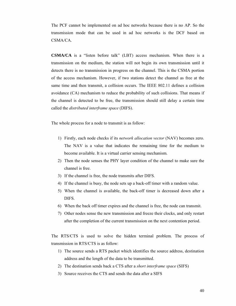
messages from different nodes. A contention based MAC protocol like CSMA/CA is

implemented to deal with the signalling transmission, and make sure each packet

reaches its destination successfully in time. The signalling information is useful to set

up the channel and the scheduling for the real-time sessions.

Specifically for the real-time sessions, there are three main functions in the MAC layer:

the function responsible for receiving the resource reservation table, the function

performing the channel allocation and the access control, and the function responsible

for the release of reserved resources.

In the MAC layer, the resource reservation table is set up according to the

correspondent information maintained in the network layer with the help of the

signalling messages. The unicast of the RREP_B message reserves the code and slots in

the Transmission code and Reception code tables, and in the Transmission slots and

Reception slots tables in the network layer. These tables are updated by the SREP and

LREP messages as well.

The information in these code and slots tables actually instructs the MAC layer in

allocating the code channel and separating the different time slots. There are a number

122

of buffers to store the packets from the network layer that will be transmitted in the

different time slots. Once the MAC layer receives a packet from the network layer for a

certain session, it just reads the code and slots information from the tables, fragments

the packet according to the spreading code to fit in the time slot, and inserts these

fragments into the buffers linked to the corresponding time slots. An algorithm runs

periodically to set up the code for transmission and reception at the beginning of each

time slot according to the Transmission (Reception) slots tables. The node checks its

Transmission slots table every SLOT_PERIOD_TIME, sets the transmission code of

the time slot. If there is a fragment of the packet waiting in the buffer for that slot, the

MAC layer just sends it out immediately to the channel. At the same time, the receiver

is set by the Reception slots table to the corresponding reception channel to receive the

data fragment transmitted in that channel. If the MAC layer receives a fragment of a

packet in a certain time slot, it buffers it until the whole packet is received successfully.

Then the packet is sent to the network layer.

Once a node finds a route breakage or receives a RERR packet, it informs the MAC

layer to release all the reserved resources in the tables for that broken session.

Network Layer

MAC Layer

Real-time StreamTransmissionControl

MessageTransmissionControl

ResourcesReservationTable

Real-time StreamReceptionControl

MessageReceptionControl

Interface Interface

Time Slot Buffers

Single code channel

PHY Layer

Multi-code channels Multi-code channels

Time Slot Buffers

…….. ……..

TX RX

Figure 4.24 MAC layer functions in the CDMA Bus Lane protocol

Figure 4.24 shows the functions of the MAC layer working in the CDMA Bus Lane

protocol. The data from the network layer will be classified in the Interface function

123

module. The messages are sent to the Message Transmission Control module which

performs the access control in the single channel. The real-time packets are scheduled

into buffers to wait for the reserved time slots to access the allocated code channels.

The reception procedure performs the reverse actions.

The multi-channel access is instructed by the Resource Reservation Table information.

The logical relationship between the Resource Reservation Table and the other

modules are shown by dashed arrows in Figure 4.24. The information is collected from

the signalling messages through the MAC layer. It is a reflection of the reservation

tables from the network layer.

4.4.8 An example of route setup and route maintenance

Figure 4.25 shows an example of the route setup and route maintenance in the CDMA

Bus Lane protocol. The dashed lines represent the neighbourhood of nodes.

Figure 4.25 (a) to (c) show the establishment of a QoS route. Node A wants to setup a

QoS route to node G. Node A starts the route discovery by broadcasting a RREQ_B

message to its neighbouring nodes. The node that receives the route request packet

checks if a link with a suitable code and sufficient bandwidth can be built, considering

its available resources. If the node finds the suitable code and slots, it updates and

forwards the RREQ_B message. For simplicity, the figure only shows the case where a

link with sufficient bandwidth is found. Once the RREQ_B reaches the destination

node G via a path P = {A C D E G}, a RREP_B message is sent back to

node A in the opposite direction of P (Figure 4.25 (b)). On receiving the RREP_B

message, the nodes on the path P reserve the allocated resources. A QoS Bus Lane is

established for the real-time session. The data are transmitted along the path P (Figure

4.25 (c)).

Figure 4.25 (d) to (f) show the route maintenance when a code collision happens. Node

H moves into the neighbourhood of node G. One of the transmission codes of node H

( 2c ) is the same as the reception code of node G. A code collision happens at node G

and it cannot receive data from node E (Figure 4.25 (d)). Node G sends a LREQ

message to request a new allocation of resources for the link l (E, G). Node E receives

the re-allocation request, calculates the bandwidth to find new code and slots for that

124

link. When node E finds that there is enough bandwidth for the new code 6c , it

reserves the code and slots for this link, and sends a LREP packet to inform the new

reservation to node G (Figure 4.25 (e)). After node G receives the LREP, it reserves the

code 6c and allocated slots for the link. The path P has been repaired locally (Figure

4.25 (f)).

A

B

F

C

D

E

G

A

B

F

CD

E

G

A

B

F

C

D

E

G

RREQ_B RREQ_B

RREQ_B

RREQ_B

RREQ_B

RREQ_BRREQ_B

RREP_B

RREP_B

RREP_B

RREP_B

DATA

DATA

DATA

DATA

C2

C3

C5

C2

(a) (b) (c)

C2

C3

C5

C2

A

B

F

C

D

E

G

DATA

DATA

DATA

DATA

(d) (e) (f)

C2

C3

C5

C6

A

B

F

C

D

E

G

DATA

DATA

DATA

DATA

C2

C3

C5

C2

H

vC2

C2

DATA

Reception link collision in node G

A

B

F

C

D

E

G

DATA

DATA

DATA

LREQ

C2

C3

C5

H

vC2

C2

DATA

LREP

H

v

C2

DATA

C2

A

BC

D

DATA

DATA

(g) (h) (i)

C2

C7

A

B

F

C

D

E

G

RERR

A

BC

D

F E

G

F E

G

C5

RERR

RERR

RREQ_B

RREQ_B

RREQ_B

RREQ_B

RREQ_B

RREQ_B

RREP_B

RREP_B

RREP_B

DATA

Figure 4.25 An example of route setup and route maintenance with QoS routing

125

Figure 4.25 (g) to (i) show the route maintenance when the path P is broken. In Figure

4.25 (g), node E moves outside of the neighbourhood of node D, and node G moves

inside of the neighbourhood of node F at the same time. Node E cannot hear from node

D any longer, so it announces the route breakage to node G by sending a RERR

message. The node D also realises the breakage by the absence of the periodic Hello

Message from node E. Node D sends a RERR message to inform the source node A.

Every node receiving a RERR message clears all the reserved resources for this session

and forwards the RERR message to the destination or source nodes. Once node A

receives the RERR message, it clears its resource reservation. If the session is still alive,

node A initiates a new RREQ_B message to set up a new QoS path for the session. The

QoS path P = {A B F G} is established by the RREQ_B/RREQ_P process

(Figure 4.25 (h)). The data continue to transmit along the new path with the reserved

resources (Figure 4.25 (i)).

4.5 Conclusions

This chapter proposed the specification of the CDMA Bus Lane routing protocol. It is a

cross layer QoS design which combines the network layer with the MAC layer to deal

with the QoS routing and resources reservation for real-time communications in mobile

ad hoc networks. The QoS routing protocol implements the bandwidth calculation and

code allocation algorithm together with an on-demand routing protocol to calculate and

allocate the code channels and time slots at the route discovery stage. The codes and

slots are used to avoid the packet collision in the network. Once a route is set up for a

real-time session, all the allocated resources on the route are reserved for the session.

The route maintenance scheme is designed to handle the route breakage and code

collision due to the move of nodes in the ad hoc network. The performance of the

CDMA Bus Lane protocol is verified in the following chapter by simulations.

126

Chapter 5 CDMA Bus Lane Simulation Modelling and Results

The details of the proposed CDMA Bus Lane routing protocol have been explained in

Chapter 4. The performance of the QoS routing protocol is measured through a

simulation model built using the OPNET Modeller [OPNET02].

The OPNET Modeller is an event driven communication network simulator. An

OPNET model includes a hierarchical structure of models composed of a network

model, node models and process models. A network topology can be set up easily in

the network level. Each node in the network level is composed of interconnected

modules in the node level. Each module is defined as a process or a set of processes in

the process level. A process is described by a finite state machine (FSM). The C/C++

language is used to programme the functionality of each state at the code level of

OPNET models.

This chapter describes the modelling in OPNET of the mobile ad hoc network which

implements the proposed CDMA Bus Lane routing protocol. The model is simulated,

verified and validated. The code allocation algorithm described in Section 4.3 is

implemented and tested in order to show its features and potential benefits. The

implemented CDMA Bus Lane routing protocol is firstly simulated in a static ad hoc

network and compared to two other routing protocols which have little or none support

from the lower layers. The simulation results enforce the importance of the cross layer

cooperation. The QoS routing protocol is also compared to a best-effort CDMA based

routing protocol without QoS consideration. The simulations are performed in

scenarios with different node speed limits generated by the Random Waypoint

Mobility Model [CBD02] and different required session data rates. The last group of

simulations compare the CDMA Bus Lane routing protocol with a TDMA-based QoS

routing protocol, which is also a cross-layer design solution [ZC02].

127

5.1 The CDMA Bus Lane Simulation Modelling

The simulation model for the CDMA Bus Lane routing protocol is created based on the

AODV simulation model [Gue01] with the necessary modifications required by the

CDMA Bus Lane routing protocol.

Firstly, the application layer has been modified to generate real-time streams with

constant bandwidth, and the bandwidth requirement information is appended to the ICI.

Secondly, because there are many differences between AODV and CDMA Bus Lane in

their network layers, which are the most important part of routing protocols, almost all

the functions, information tables and even the formats of the signalling packets have

been changed in the code and process levels to realize all the functionalities of the

CDMA Bus Lane proposed in Chapter 4. Over 4000 lines of new code have been

programmed in C language to make the necessary changes in the network layer.

Thirdly, differently from the AODV model, which was built on an IEEE 802.11 MAC

layer, the MAC layer of the CDMA Bus Lane protocol combines CDMA, TDMA and

contention based access together to support and cooperate with the network layer for

route discovery, resource reservation and access control. Therefore, the whole MAC

layer has been modified. Moreover, another pair of transmitter and receiver has been

implemented for real-time transmissions. Finally, there are minor changes in the

mobility module.

This model provides a test bed for simulations and comparisons with other routing

protocols. The details of the simulation model are described as follows.

5.1.1 The Network Model

A network model is a description of the network structure and its topology. Figure 5.1

shows an example of an ad hoc network composed of 30 nodes inside an area of 1000

×1000 square meters. Because there is not a fixed structure in ad hoc networks, all the

30 nodes are distributed randomly and can move inside the network area. All the nodes

have the same functionality. Therefore, the whole network is built using one type of

node model: the wireless mobile station.

128

Figure 5.1 The ad hoc network model

5.1.2 The Node model

As is shown in Figure 5.2, the node model is built in layers. In the CDMA Bus Lane

implementation, the emphasis is on the network and the MAC layers of the model.

Therefore, some of the upper layers have been legitimately omitted for simplicity. A

OPNET mobility model was created using the Random Waypoint Mobility Model

[CBD02] to allow nodes to move randomly inside the network area.

a) The Application layer: There are three modules in this layer to complete simple

functions in the application layer. The source module (modified from a source module

provided by OPNET) is a packet generator. It generates data with constant bit rate

(CBR) to simulate a source for real-time sessions. The generated packets are delivered

to the immediate lower module, the app_manager. The app_manager assigns a random

destination address to the incoming packet and generates a service request to the

network layer with the bandwidth requirement in the form of an Internal

129

Communication Interface (ICI). Along with the ICI, a packet is sent to the network

layer. The sink module (provided by OPNET) is used to simply destroy the received

packets from the network layer.

Figure 5.2 The CDMA Bus Lane node model

The description of each layer of the mobile node model is given below:

b) The network layer: There is only one module in this layer, the BusLane_routing

module. The BusLane_routing module aims to receive the packets from the application

layer, to provide and maintain the QoS routing with sufficient bandwidth, and to

indicate the reserved resource information to the MAC layer. This is the most

important layer of the simulation model, which realise the QoS routing with reserved

sufficient bandwidth, and the route maintenance in the dynamic network topology. The

details of the BusLane_routing module are described in its process model.

130

c) The MAC layer: The functions of the MAC layer are implemented in the

BusLane_mac module. It is constructed according to the CDMA Bus Lane MAC layer

scheme (described in Section 4.4.7). The BusLane_mac module cooperates with the

network layer to transmit and receive the messages and data packets, and to reserve the

code and slots for each link on QoS routes. The details are described in its process

model.

d) The PHY layer: Two sets of transceiver modules are implemented. They are

modified versions from the IEEE 802.11 standard PHY layer module provided by

OPNET. The signal_tx and signal_rx modules are used to transmit and receive the

signalling messages in the data channel. The session_tx and session_rx modules are

used to handle the real-time packets. The channel for the real time sessions switches to

different spreading codes in accordance to the scheduling of the time slots controlled

by the MAC layer.

e) The mobility module: This module controls the movement of the wireless node in

terms of speed, waiting time, direction, etc. The Random Waypoint Mobility Model

[CBD02] is implemented. The details are described in its process model.

5.1.3 The Process Models

The functionality of each module is described by the process model. In OPNET,

specific circular icons represent states, and lines represent transitions between states.

The actions inside a state are separated in enter executives (which are performed when

a processes transits to that state) and exit executives (which are performed before the

process leaves that state). Green circles represent forced states, which means the enter

and exit executives are performed at once, then the process automatically transits to the

next appropriate state. Red circles represent unforced states, where the enter executives

are invoked and then the process pauses on that state to wait for a specific event. When

this event occurs, the exit executives are performed and the process transits to the next

appropriate state. The operations performed in each state are coded in C or C++

language.

131

a) Application manager process

The primary function of this process is to assign the destination address and the

required bandwidth for the session starting from this node. Figure 5.3 shows the

OPNET FSM for the application manager process.

Figure 5.3 Application manager process

Firstly, each wireless mobile station at the init state initiates the session attributes

including the random starting time of the session, the IP addresses of this mobile

station and the destination mobile station, and the required bandwidth of the session.

Note that, the destination address must not be the same address of the mobile station

itself. Then, the state of the process changes to idle.

If the Application manager process is in the idle state and a packet arrives from the

source module, then this mobile station will start a session. The state transits to tx in

order to start the session with the required parameters. The Application manager

requests a service from the network layer and installs an ICI including the destination

IP address and the required bandwidth of the session. After that, it sends the ICI along

with the data packet to the network layer.

b) Bus Lane routing process

This is the most important process that includes eight forced states and an idle state.

The process is implemented according to the specification of the CDMA Bus Lane

routing protocol described in Section 4.4. Each state is described by a set of actions and

132

triggered by a particular event. Figure 5.4 shows the OPNET model for the Bus Lane

routing process.

Figure 5.4 Bus Lane routing process

- Init state: In this state, the user attributes and different variables are initialised

(routing table, transmission (reception) code table, etc). In order to send Hello

Messages to neighbours, a self-interrupt is scheduled to initiate the first Hello

Message within the first_hello_intrvl, which is a randomly generated value between

0 to 1 second following a uniform distribution. Another self-interrupt is set up to

collect the simulation results when the simulation finishes. After performing this

initialisation, the process transits immediately to the idle state.

- App_Ariv state: The routing process transits to this state when a service request is

received from the application layer to build a QoS route. The first action is to

extract the ICI associated with the received packet in order to get the required data

rate for the real-time session and the destination IP address. Then the received data

packet is encapsulated into a BusLane_Data packet (a CDMA Bus Lane OPNET

data format), the header fields are filled with the correct values including

source/destination address and required data rate for the session. After that, the

BusLane_data_pk_receive_from_appl(Packet* pk_ptr) function is called in order to

133

route the packet to its final destination. The function is implemented according to

the process model described in Section 4.4.5.

- Rcv_Mac state: Upon receiving an incoming packet from the MAC layer, the

process transits from idle to the Rcv_Mac state. First the type of the received packet

is checked. The packet can be a signalling message (RREQ_B, Hello Message, etc)

or a data packet. According to the type of the packet the appropriate function to

process the packet is called. Signalling messages always trigger the functions that

set up, maintain and release routes, or update neighbouring node information. Data

packets are simply transmitted to the next hop ad hoc network node. If a data

packet arrives at its final destination, the packet is sent to the application layer.

- Handle_RREQ_Rebroadcast state: The process transits to this state when a

RREP_WAIT_TIMEOUT timer expires for a given destination (the destination IP

address is extracted from the interrupt code). It means the current node still has not

received a route reply to its request. In this case, the current state checks whether a

re-broadcast is possible or not (depending on the number of retries threshold). If the

maximum authorised number of retries is reached, the discovery process for that

destination is aborted. Consequently, any data packet waiting for this route is

dropped from the buffer. Otherwise, a function is called to rebroadcast a RREQ_B

packet.

- Say_Hello state: a periodic self-interrupt triggers the transition to the Say_Hello

state every “hello_interval” seconds. The node must broadcast a Hello Message in

order to advertise its presence and send its updated node information to the

neighbourhood. A function BusLane_Create_Hello() is called to create and

broadcast the Hello Message, and then another self-interrupt is set for the next

broadcast in “hello_interval” seconds.

- NB_Expi state: This state is called when a node fails to receive a Hello Message

from a neighbour within a HELLO_WAITING_TIME. In this case, the neighbouring

node is deleted from the Neighbour information table. The next action is to check

the Bus Lane routing table to find out if the neighbour in question is on the up-

stream (previous hop) or down-stream (next hop) of any active session across the

134

node. If the down-stream link is broken, a RERR packet is sent to the up-stream

neighbour of that session path in order to reach the source node of the session. If

the node itself is the source node or the RERR packet reaches the source node, a

new route request is broadcast. If the up-stream link is broken, a RERR packet is

sent the down-stream neighbour of that session path in order to reach the

destination node. The reserved resources for that session are released.

- Code_Reallocate state: This state is called when a code collision happens on the

receiving link of a certain session across the node. The session ID is associated

with the interruption code. A function BusLane_code_collision(int session_ID) is

called to generate a LREQ message to reallocate the code and slot for that link.

- Collect state: The process transits to this state at the end of the simulation in order

to collect and handle the simulation results including the total transmitted packets

of the node and the session successful transmission rate. The statistics are written

into a file which is created at the beginning of each simulation.

c) BusLane_mac process

The BusLane_mac process supports the CDMA Bus Lane routing protocol by

transmitting the signalling messages, setting up and scheduling the channels for the

real-time packet transmission.

Figure 5.5 BusLane_mac process

135

Figure 5.5 shows the OPNET BusLane_mac process model. The INIT state initialises

the process and the IDLE state waits for events. The other four states are described

below.

- Arriv_Up state: This state is triggered by the packet arrival from the network layer.

First the type of the received packet is checked, and then the appropriate function is

called according to the type of the packet. A data packet is fragmented and buffered

to the appropriate queue according to the allocated time slots. A signalling packet is

processed by the appropriate function to set up the information tables for the

channel allocation and the scheduling. Then the signalling packet is sent to the

appropriate buffer for transmission.

- TX state: It is used to handle the transmission of the signalling messages. It is

triggered by a self-interrupt to send the packet to the transmitter. The transmission

implements a simplified random access scheme. All the messages are assumed to

be received successfully by the receiving node.

- RX state: This state is triggered by the reception of a packet from one of the

receivers in the PHY layer. The packet could be either a signalling message or a

data packet fragment in a time slot. If a signalling message is received, the

appropriate function is called to set the useful information for the MAC layer in the

tables and then transmit the message to the network layer. If a data packet fragment

is received, it is put into a buffer and it will wait until all the fragments of the

packet are received. Then the full data packet is sent to the network layer.

- SET_CHANNEL state: A periodic interrupt is set to trigger this state. It works at the

beginning of every time slot in order to set the transmitting and receiving channels

for the time slot according to the Transmission (Reception) slot table. If there is a

packet buffered in the corresponding queue of the current time slot, the packet is

sent out to the appropriate channel immediately.

d) Mobility process

Node mobility is one of the primary characteristics of mobile ad hoc networks. This

process allows nodes to move with random speed and random direction. Figure 5.6

136

shows the OPNET mobility process model, which implements the functions of the

Random Waypoint Mobility Model [CBD02].

Figure 5.6 Mobility process

For each wireless mobile station, a random position is selected within the whole

network area. The value of the mobility attribute determines if the mobile station will

move or not. If the mobile station is set to be a fixed node, the process transits to the

Idle state directly. Otherwise, the mobile station is set to be a mobile node and transits

to the Init_mv state to initialise the movement parameters. The speed of the mobile

node is randomly generated within a speed limit and a target position, which is selected

randomly within the network area. The step-range, which represents the distance of one

step, is calculated by the selected speed and the periodic time of a step.

In the state Move, the next position is calculated according to the step-range and

direction. Both parameters have been calculated in the state Init_mv. The current

position of the node is replaced by the next step position. After each step of movement,

the mobile node checks if the target position has been reached or not. If the mobile

node did not reach its target position after that step, it returns to the idle state and waits

for the next step time. The mobile node transits between the Move state and the Idle

state periodically to move step by step, until it reaches the target position. When the

node reaches its target position, it transits to the idle state and waits for a random pause

time. Then, it goes back to the state Init_mv for another trip.

137

5.2 Simulation Modelling Verification and Validation

The work in this thesis is to design a cross-layer QoS routing protocol for mobile ad

hoc networks. Verification and validation are required to prove the protocol is correctly

implemented in the simulation model and the simulation results are correct. Model

validation is usually defined as the “substantiation that a computerised model within its

domain of applicability possesses a satisfactory range of accuracy consistent with the

intended application of the model” [Sch79]. Model verification is often defined as

“ensuring that the computer program of the computerised model and its

implementation are correct” [Sch79].

A model should be developed for a specific purpose (or application) and its validity is

determined with respect to that purpose [Sar98]. The purpose of the CDMA Bus Lane

routing protocol is to setup, reserve and maintain a route with sufficient bandwidth for

each real-time session in mobile ad hoc networks by combining a code allocation

algorithm with a QoS routing algorithm. The code allocation algorithm is validated in

Section 5.3, and the functionality of the fully implemented QoS routing protocol is

validated by various simulation scenarios in Section 5.4.2 of this thesis. The result

shows that the model representation of the protocol entity is “reasonable” for the

intended purpose of the model.

According to [Sar98], a program must be tested for correctness and accuracy for

verification. First, the simulation functions should be tested to see if they are correct.

Next, each sub model and the overall model should be tested to see if they are correct.

Actually the CDMA Bus Lane routing protocol model was verified during the model

implementation. The code of each function has been tested and debugged. The

verification of each sub model and the overall model was performed in the different

layers and function modules within the step by step building process in OPNET. This

section focuses on the details of the model verification.

The mobility module can be verified easily by the animation recording function

provided by OPNET. The moving of the nodes is recorded during the simulation time.

The animation shows that all the nodes can move in the randomly selected directions

and with speeds within the speed limits.

138

Event traces are used in [BGK02] to verify the routing protocol implemented using NS

(network simulator). A similar technique can be used for the CDMA Bus Lane

verification. Files are created by the C code in OPNET to trace the signalling messages

and record the living states of the different layers in each node. The routing function in

the network layer is verified by collecting route and resource allocation information to

ensure that QoS routes are built with the correct reserved resources. The MAC layer

function is verified by showing that the packets are transmitted and received in the

scheduled slots with the reserved codes. Simulations are designed to verify the

correction of the implemented functions in each layer.

5.2.1 Verification of the network layer implementation

The network layer is responsible for setting up and maintaining a QoS route with the

reserved code and slot resources for each real-time session. The verification can be

divided into QoS route setup and route maintenance.

a) QoS route setup

The verification of the QoS route set up should consider three issues. Firstly, a path can

be built for a required destination. Secondly, the codes and slots can be allocated

properly for each link with the RREP_B message reaching the source node through the

reverse path. Thirdly, the routing protocol is bandwidth aware, that it always selects a

route with sufficient bandwidth.

The simulation model for the CDMA Bus Lane routing protocol has been described in

Section 5.1. An ad hoc network with 30 nodes is generated in an area of

1000m×1000m. The constant data rate of each real-time session is 20kbps. SF varies in

the range of 8 to 128, which are between level 3 and 7 of an OVSF code tree. The

packet size is 1kbit, and the minimum length of a packet after code spreading is 8kbit.

Therefore, a packet occupies at least one time slot. In the simulation, 5 sessions are

requested by the nodes with ID numbers from 0 to 4. Each node selects the destination

randomly. The ID of the allocated slots starts from 0, and the ID of the allocated codes

starts from 1. The five selected routes are shown in Figure 5.7 with five different

colours.

139

Figure 5.7 Route setup for five sessions

A file is created to trace the code and slot reservation with the travel of the RREP_B

packets. The file firstly records the route request by a source node to a certain

destination node. Once the destination node receives the RREQ_B packet, it sends a

RREP_B back. Each node receiving a RREP_B writes the file with the allocation

information, until the RREP_B reaches the source node. The content of the trace file

with the five required sessions is as follows: (1) Session (from node 0 to node 20): route request is initiated by node 0: ***** The node address is 0 ***** ****** The start time is 0.159606 ***** ****** The dest node is 20 ***** rreq reaches the destination node 20: ****node 20 *** time: 0.165901 ****The RREQ comes from 19 ****The R_code is 2**** ****Slot is 0**** resources are reserved in node 19 when receiving a rrep:

140

**** (0) --> node 19 --> (20) ****** time: 0.166081 ****The T_code 2 use Slot 0 ****** ****The R_slot is 0 for Code 1 ****** rrep reaches the source node 0 and reserve the resources: **** node 0 --> (19) ****** time: 0.171881 ****The T_code 1 use Slot 0 ****** The route has been built for node 0 ------%%%%%%%%%%%%%%%%%%%%----- (2) Session (from node 1 to node 0): route request is initiated by node 1: ***** The node address is 1 ***** ****** The start time is 1.064952 ***** ****** The dest node is 0 ***** rreq reaches destination node 0: ****node 0 *** time: 1.068301 ****The RREQ comes from 1 ****The R_code is 3**** ****Slot is 0**** rrep reaches the source node 1 and reserve the resources: **** node 1 --> (0) ****** time: 1.074081 ****The T_code 3 use Slot 0 ****** The route has been built for node 1 ------%%%%%%%%%%%%%%%%%%%%----- (3) Session (from node 2 to node 25): route request is initiated by node 2: ***** The node address is 2 ***** ****** The start time is 2.156815 ***** ****** The dest node is 25 ***** rreq reaches destination node 25: ****node 25 *** time: 2.194701 ****The RREQ comes from 23 ****The R_code is 1**** ****Slot is 0**** resources are reserved in node 23 when receiving a rrep: **** (14) --> node 23 --> (25) ****** time: 2.195081 ****The T_code 1 use Slot 0 ****** ****The R_slot is 0 for Code 3 ******

141

resources are reserved in node 14 when receiving a rrep: **** (9) --> node 14 --> (23) ****** time: 2.200681 ****The T_code 3 use Slot 0 ****** ****The R_slot is 0 for Code 2 ****** resources are reserved in node 9 when receiving a rrep: **** (2) --> node 9 --> (14) ****** time: 2.204881 ****The T_code 2 use Slot 0 ****** ****The R_slot is 0 for Code 1 ****** rrep reaches the source node 2 and reserve the resources: **** node 2 --> (9) ****** time: 2.209881 ****The T_code 1 use Slot 0 ****** The route has been built for node 2 ------%%%%%%%%%%%%%%%%%%%%----- (4) Session (form node 3 to node 2): route request is initiated by node 3: ***** The node address is 3 ***** ****** The start time is 2.534265 ***** ****** The dest node is 2 ***** rreq reaches destination node 2: ****node 2 *** time: 2.538900 ****The RREQ comes from 4 ****The R_code is 4**** ****Slot is 0**** resources are reserved in node 4 when receiving a rrep: **** (3) --> node 4 --> (2) ****** time: 2.544480 ****The T_code 4 use Slot 0 ****** ****The R_slot is 0 for Code 3 ****** rrep reaches the source node 3 and reserve the resources: **** node 3 --> (4) ****** time: 2.544881 ****The T_code 3 use Slot 0 ****** The route has been built for node 3 ------%%%%%%%%%%%%%%%%%%%%----- (5) Session (from node 4 to node 24): route request is initiated by node 4: ***** The node address is 4 ***** ****** The start time is 2.773082 ***** ****** The dest node is 24 *****

142

rreq reaches destination node 24: ****node 24 *** time: 2.812301 ****The RREQ comes from 21 ****The R_code is 1**** ****Slot is 0**** resources are reserved in node 21 when receiving a rrep: **** (15) --> node 21 --> (24) ****** time: 2.812881 ****The T_code 1 use Slot 0 ****** ****The R_slot is 0 for Code 3 ****** resources are reserved in node 15 when receiving a rrep: **** (9) --> node 15 --> (21) ****** time: 2.818281 ****The T_code 3 use Slot 0 ****** ****The R_slot is 1 for Code 2 ****** resources are reserved in node 9 when receiving a rrep: **** (4) --> node 9 --> (15) ****** time: 2.823081 ****The T_code 2 use Slot 1 ****** ****The R_slot is 1 for Code 1 ****** rrep reaches the source node 4 and reserve the resources: **** 4 --> (9) ****** time: 2.827881 ****The T_code 1 use Slot 1 ****** The route has been built for node 4 ------%%%%%%%%%%%%%%%%%%%%-----

As shown in Figure 5.7, the codes (represented by C in the figure) and slots

(represented by S in the figure) are allocated for each session correctly. The allocated

orthogonal codes avoid collisions within the transmission range of neighbouring nodes.

At a cross node, different slots are used to schedule active multiple sessions. In a node,

the transmission and reception can be performed at the same time by using two

different orthogonal spreading codes on separated transmitter and receiver.

In order to check the slot calculation in a cross node, a trace file is built for node 9. The

number of required slots (N_slots) depends on the ID of the allocated code (CodeID).

For a 4-code-remain code set, the relationship between CodeID and code level (L) is:

L = int [(CodeID -1)/4] + 3 (5.1)

and the SF can be calculated by L:

143

SF = L2 (5.2)

Assume that a 20 kbps stream takes one slot each frame, the N_slots can be represented

by:

N_slots =( SF/8) × (BW_session/20) (5.3)

Where BW_session (kbps) is the bandwidth of a real-time session. In Figure 5.7, each node has 32 slots, and the required session bandwidth is 20kbps.

The first session across node 9 allocates code 1 to be the reception code and code 2 to

be the transmission code. According to Equations (5.1) to (5.3), the N_slots can be

calculated by:

N_slots(code 1) = 1)8/2( 3)4/1int( ×+ = 1 (5.4)

and

N_slots(code 2) = 1)8/2( 3)4/2int( ×+ = 1 (5.5)

Therefore, slot 0 is allocated to both transmission and reception links for the session. The same calculation is also done for the second session across node 9. Slot 1 is

allocated.

According to Equation (4.4), the available bandwidth for both the transmitter and the

receiver can be calculated by:

Slot_available = Slot_total –∑i

iusedSlot )(_ = 32 – (1+1) = 30 (5.6)

Therefore, there should be 30 slots left in node 9 with these two sessions. The trace file

is as follow:

The slot reserved in node 9: **** The transmission slots of node 9 ****** ****The T_slot 0 is used ****** ****The T_slot 1 is used ****** ****There are 30 slots available in transmitter ******

144

**** The reception slots of node 9 ****** ****The R_slot 0 is used ****** ****The R_slot 1 is used ****** ****There are 30 slots available in receiver ******

This proves the simulation results for the slot calculation and allocation are in

accordance with the expected mathematical calculations from the equations presented

in Chapter 4.

In order to check if the routing is QoS aware with regard to the requested bandwidth,

the mobile station with ID 23 is blocked manually by setting to unavailable all the slots

in the node (Figure 5.8). In this scenario, a longer route (2 9 14 16 29

25) is set up with sufficient bandwidth to replace the shorter route (2 9 14 23

25) built in Figure 5.7. That shows the QoS aware routing has been implemented

successfully.

Figure 5.8 QoS routing verification

The same trace files are also built for all the simulations in this chapter. All of these

files show that the QoS route establishment for CDMA Bus Lane is successful.

145

b) QoS route maintenance

The implementation of the proposed route maintenance scheme (described in Section

4.4.6) should be verified. The mobility of nodes can cause route breakage or code

collision; both cases need to be simulated and verified.

In the simulation, all the nodes in the ad hoc network move within a speed limit of

10mps. The route breakage and the rebuilding of the route are traced and recorded in

files. For example, node 10 is the source of a route to node 9 (10 15 9) at the

beginning of the simulation. The setting up of the route is traced in the file as:

rreq reaches destination node 9: ****node 9 *** time: 6.423101 ****The RREQ comes from 15 ****The R_code is 7**** ****Slot is 3**** ****Slot is 4**** **** The session number is 3 resources are reserved in node 15 when receiving a rrep: **** (10) --> node 15 --> (9) ****** time: 6.427881 The session number is 2 ****The T_code 7 use Slot 3 ****** ****The T_code 7 use Slot 4 ****** ****The R_slot is 3 for Code 5 ****** ****The R_slot is 4 for Code 5 ****** rrep reaches the source node 10 and reserve the resources: **** node 10 --> (15) ****** time: 6.429081 The session number is 1 ****The T_code 5 use Slot 3 ****** ****The T_code 5 use Slot 4 ****** The route has been built for node 10 ------%%%%%%%%%%%%%%%%%%%%-----

However, the link l (10, 15) breaks because of the mobility of the nodes. That is traced

in the file as:

The node 10 lost a neighbour of node 15 at 8.435161 ^^^^ The node 10 lost a next hop node 15 at 8.435161 on session 1 ^^^^ The node 10 is the source node. Rebuild a route for the session

146

The node 15 lost a neighbour of node 10 at 8.440161 **** The node 15 lost a previous hop node 10 at 8.440161 on session 2 **** The reservation in node 15 has been released at 8.440161*** RERR is received by node 9 at 8.445020 **** The reservation in node 9 has been released at 8.445020*** ------%%%%%%%%%%%%%%%%%%%%-----

The route breakage is reported to both sides of the route. The node receiving the RERR

message releases all the resource reservation for the session and forwards the RERR

message to the source or destination node. The node 10 is the source node. It releases

the resources as well, and rebroadcasts a RREQ_B message to search for a new path to

the destination node 9. The new path (10 8 9) is found as follow:

rreq reaches destination node 9: ****node 9 *** time: 8.479701 ****The RREQ comes from 8 ****The R_code is 8**** ****Slot is 5**** ****Slot is 6**** **** The session number is 3 resources are reserved in node 8 when receiving a rrep: **** (10) --> node 8 --> (9) ****** time: 8.479881 The session number is 4 ****The T_code 8 use Slot 5 ****** ****The T_code 8 use Slot 6 ****** ****The R_slot is 2 for Code 9 ****** ****The R_slot is 3 for Code 9 ****** ****The R_slot is 5 for Code 9 ****** ****The R_slot is 6 for Code 9 ****** rrep reaches the source node 10 and reserve the resources: **** node 10 --> (8) ****** time: 8.485681 The session number is 1 ****The T_code 9 use Slot 2 ****** ****The T_code 9 use Slot 3 ****** ****The T_code 9 use Slot 5 ****** ****The T_code 9 use Slot 6 ****** The route has been built for 10 ------%%%%%%%%%%%%%%%%%%%%-----

The trace file shows that the route breakage detection and route re-establishment

schemes have been implemented successfully.

147

Another problem comes from the code collision. A code collision is traced in the file as

follow: In the example, the link l (2, 4) starts to suffer interference from the

transmission of a neighbouring node (node 16). This is detected by node 4.

Code collision detected by node 4: $$$$$ The node 4 find a neighbour 16 which has a T_code 4 affect the R_link of session 2 on Link l (2, 4),time:10.245361 $$$$$ node 4: The code on link l (2,4) for session 2 should be changed. time: 10.245361 $$ the link is on the session from 7 to 29 **

Node 4 sends a LREQ message to node 2 to reallocate the resources. After the

calculation, the resources are reallocated for the link, which are traced in the file as

follow: Resources reallocation in node 2: @@@@@@@ The new code for the link from 2 to 4 is 10 time: 10.248869 @@@@@@@ The T_slot is 2 @@@@@@@ The T_slot is 9 @@@@@@@ The T_slot is 10 @@@@@@@ The T_slot is 11 @@@@@@@ In the lrep the slot reserved are 2, 9, 10, 11 with code 10.

The LREP message takes the newly reserved information to node 4. The code collision

is repaired successfully. The simulation shows that the repair scheme for code collision

is implemented correctly in the simulation model.

5.2.2 Verification of the MAC layer implementation

The resource reservation performed in the network layer must be enforced in the MAC

layer. The channel is scheduled in 32 time slots. The periodic interrupts are set up to

send and receive packets in each slot. The channels for both transmission and reception

are set to the reserved codes at the beginning of each slot. A packet can be successfully

received only if the code and the slot set on the receiver of the receiving node are the

same as those set on the transmitter of the transmitting node. A trace file is built to

record the transmission and reception of a node. The following part of the trace file

gives an example of the two active links on node 1.

148

node 1 --> (8) ****** time: 0.691681 ****The T_code 2 use Slot 0 ****** node 1 --> (2) ****** time: 0.936481 ****The T_code 2 use Slot 1 ******

The packets are sent to different destinations in two slots. One is for the node 8 in the

slot 0, and the other is for the node 2 in the slot 1. Both of them use the code 2 to set

the transmission channel. The receiver nodes 8 and 2 also need to set their channels to

the same code as the node 1 at the corresponding time slots. The packets are received

successfully.

slot 0: ****-- The T_channel of node 1 is set by code: 2. time: 0.950000 *** ****-- A data is send to Lower layer from MAC in slot 0 *** ^^^^ The R_channel of node 8 is set by code: 2 time: 0.950000 ^^^

******* a data is received by node 8 from node 1. *****

slot 1:

****-- The T_channel of node 1 is set by code: 2. time: 0.951563 *** ****-- A data is send to Lower layer from MAC in slot 1 *** ^^^^ The R_channel of node 2 is set by code: 2 time: 0.951563 ^^^ ******* a data is received by node 2 from node 1. *****

The node 2 did not receive the packet that the node 1 transmitted to the node 8, because

node 2 receiver channel was set to the code 2 only at the time slot 1. The simulation

verifies the successful implementation of the MAC layer for the simulation model.

The functions of the CDMA Bus Lane routing protocol have been implemented and

verified step by step. The simulation model proved to be constructed successfully. The

validation of the protocol is performed in the simulations in Sections 5.3 and 5.4.

149

5.3 Simulation and results of the code allocation algorithm

The simulation of the code allocation on fixed routes was implemented using OPNET

simulator. A hundred nodes are generated in an area of 2000×2000 m 2 (the same model

is used by [MPGW06]). The location of a node is generated randomly using a uniform

distribution. The transmission range for each node is 300m, which is within the

transmission range of IEEE 802.11b WLAN [LBR03].

This simulation studies the performance of the code allocation algorithm described in

Section 4.3, and tests the capacity of a CDMA-based ad hoc network using the code

allocation algorithm with different number of active sessions. There are no packet

transmissions among mobile nodes. Only codes are allocated on existing routes with

the bandwidth calculation.

Therefore, the only functionality of the mobile node model in OPNET is to find its

neighbours. A control node is created as a coordinator in the simulation to set up the

optimal shortest path for each source/destination pair according to the neighbouring

information recorded in each node and allocate the codes for each link on paths using

the proposed code allocation algorithm. The pair of source and destination nodes for

each session is selected randomly. Assume the required data bandwidth in each session

is BWd = 32kbps, the SF changes in the range (8 – 128), which are between level 3 and

7 of an OVSF code tree. 4-codes-remain code set is used to generate the allocated

codes. The maximum channel bandwidth is: BWc = BWd × SFmax.

Table 5.1 Performance of the code allocation algorithm using 4-codes-remain code set

Table 5.1 shows a series of performed simulations. For each simulation, a certain

number of concurrent sessions were requested. The proposed code allocation algorithm

(Section 4.3) was used for each requested session. The number of sessions required to

be set up is represented by NS. The number of total links for the sessions is represented

NS 5 10 15 20 25 30 35 40 45 50 55 60 65 70 75 80NL 20 31 62 80 108 127 152 181 203 228 246 258 269 282 294 312NC 4 5 6 6 8 9 9 10 10 11 11 11 11 11 11 11ND 0 0 0 0 0 0 0 0 0 0 0 1 2 4 7 9

150

by NL, and the number of required codes is represented by NC. The table shows the

amount of required links for the requested sessions and the number of codes needed to

avoid interference between these concurrent sessions (the codes on rejected sessions

are not counted). For each requested session a bandwidth calculation was performed. If

there was not enough bandwidth for a session, the request was denied. The number of

denied sessions (ND) is also given in the table. The results show the capacity of the ad

hoc network in implementing the code allocation algorithm using 4-codes-remain code

set in different session loads.

50 55 60 65 70 75 800

5

10

15

20

25

Number of Sessions

Ses

sion

Blo

ckin

g R

ate

(%)

n = 1n = 2n = 4n = 8

Figure 5.9 Performance of different n-codes-remain code set

In order to evaluate the effect of using different values of “n” in the n-codes-remain

scheme, different n-codes-remain code sets were simulated with n=1, 2, 4, 8, and the

results are shown in Figure 5.9. The performance of the code allocation is measured in

terms of session blocking rate, which is defined as the number of denied sessions over

the number of requested sessions. Obviously for n=1 there are less available codes, but

a shorter SF allows more sessions across a node; for n=8 there are more available codes,

however, with a longer SF the allowed number of sessions across a node is reduced.

Therefore, the selection of a suitable n needs to balance the advantages of having

sufficient available codes against the reduction of the available bandwidth for data

transmission. Moreover, the network load should also be considered.

151

0 10 20 30 40 50 60 70 800

10

20

30

40

50

60

Number of Sessions

Ses

sion

Blo

ckin

g R

ate

(%)

TDMA SystemCDMA Bus Lane

Figure 5.10 Session blocking rate of the CDMA Bus Lane scheme versus a pure TDMA scheme

Another simulation was performed to compare the CDMA code allocation scheme (4-

codes-remain code set) with a scheme using pure TDMA, which uses an ideal slot

allocation algorithm. The network model built for the TDMA scheme is similar to the

one built for the CDMA Bus Lane scheme (as described in the previous simulation).

Both schemes do the resource allocation on the same generated routes.

The TDMA scheme uses a time slot allocation algorithm to avoid packet collision. All

the sessions share the same code channel and a minimum spreading factor of SFmin = 8

is used to offer more available bandwidth for multiple sessions across a node. The

channel is simply divided in 16 time slots; each slot can transmit or receive a packet

whose data was spread by SFmin. The packet whose data was spread using the

maximum spreading factor (SFmax = 128) will occupy all the slots. If a transmission

cannot find enough time slots, the request is denied.

The blocking rate was calculated by the number of denied sessions over the number of

requested sessions. The simulation results show that the performances of the two

schemes are almost the same in low traffic load; with the increase of the requested

152

sessions, the CDMA Bus Lane scheme provides better performance than the TDMA

scheme, allowing a much greater number of sessions to be accepted.

5.4 Simulations and results of the CDMA Bus Lane QoS routing protocol

5.4.1 Simulation environment

The performance of the CDMA Bus Lane QoS routing protocol is investigated with the

simulations shown in this section. The simulation model for the QoS routing protocol

has been described in Section 5.1. All the simulations are processed at packet level.

An ad hoc network of 30 nodes is generated in an area of 1000m×1000m (the same

network model with [SPC03] and [YL06]). The transmission range of each mobile

node is 250m, which is within the transmission range of IEEE 802.11b WLAN

[LBR03]. The parameters of the CDMA Bus Lane scheme are set as follows: The

allocated spreading codes are generated by a 4-codes-remain code set. The SF varies in

the range of 8 to 128, which are between level 3 and 7 of an OVSF code tree. The

transmission rate of the channel is 5.4 Mbps (IEEE 802.11b [SPC03]). There are 32

slots in a frame, and each slot has the duration of 1.5625ms, which carries 8.4kbit of

information. The packet size is 1kbit, and the minimum length of a packet after code

spreading is 8kbit. Therefore a packet can occupy one or more time slots. The

NODE_TRAVERSAL_TIME, which represents the maximum time allowed for a packet

to travel between two nodes, is set to 8ms [Gue01]. The waiting time for a reply after a

RREQ_B broadcast (called RREP_WAITING_TIME) is calculated by: 2×NODE_

TRAVERSAL_TIME ×TTL. The initial value of TTL is 2 and it is increased by two each

time there is no reply after a RREP_WAITING_TIME. In order to keep a constant data

rate for any real-time session, the buffer size in the network layer for each intermediate

node is zero. Any node needs to send the received packet immediately to the MAC

layer and forward the packet in the time slots reserved for the session. Hello Messages

are broadcast by each node every 1s. If a node has not received any Hello Message

from a neighbouring node for 2s, it deletes this neighbouring node from its

153

Neighbouring information table. For each simulation, five different simulation seeds

are used and the results are averaged.

5.4.2 Performance analysis of the CDMA Bus Lane routing protocol in a mobile environment

In order to validate the CDMA Bus Lane implementation, a group of simulations were

performed with different node speed limits. A CBR source with a data rate of 20kbps is

used to generate the real-time streams. The CDMA Bus Lane protocol generates 30

concurrent sessions in the network. The node speed limits change from 0 to 20m/s,

which simulate the movement of walking people and vehicles running in low speed on

the road. The number of transmitted and received packets is recorded in a result file. A

session is called successful when at least 90% of its packets are received [ZC02].

Table 5.2 shows the throughput (which is calculated by the number of packets received

by the destination nodes over the number of packets transmitted by the source nodes)

and the successful session rate (which is calculated by the number of successfully

received sessions over the number of the requested sessions) with different node speeds.

Speed (m/s) Throughput (%) Successful sessions (%)

Isolated loss (%)

0 100.00 100.00 0 2 94.16 90.00 0 4 90.40 76.67 0.46 7 86.77 53.33 2.81 10 85.96 46.67 1.92 15 80.45 33.33 1.99 20 79.35 26.67 0.60

Table 5.2 Performance of CDMA Bus Lane with different node speed limits

A node in the network can move outside of the transmission range of other nodes,

becoming an isolated node. Sometimes, nodes in the network can be separated into two

or more subnets due to node mobility and consequently losing the connection. These

subnets are called isolated subnets. If a source node or a destination node is an isolated

node, or they belong to different isolated subnets, an isolated problem occurs. It is not

154

possible to set up a route between the source node and the destination node during the

occurrence of an isolated problem. During an isolated problem packets are lost. The

isolated loss in Table 5.2 represents the percentage of the lost packets caused by

isolated problems.

Obviously, the throughput and the successful session rate decrease with the increase of

the node speed. The results in Table 5.2 show that the CDMA Bus Lane routing

protocol works well in walking speed. The isolated loss also changes with the node

speed. The number of lost packets of a session during an isolated problem can be

calculated by: Session_Data_Rate × Isolated_Time. With the node speed increasing,

although the chance that an isolated problem happen may increase, the isolated time

will decrease and the isolated loss may decrease as well.

The simulation results show the performance of the route maintenance in a mobile

scenario. The results also show in what speed range the routing protocol works best.

The same simulation parameters are used in the next sections for the comparison of the

CDMA Bus Lane routing protocol and other routing protocols. Speed limits from 0 to

10 mps are used in the analysis of network performance.

5.4.3 The importance of the MAC layer support

This simulation looks at the performance of the CDMA Bus Lane routing protocol in a

static ad hoc network. The MAC layer is implemented to allocate codes and separate

the channel in time slots to support the real-time sessions. The CDMA Bus Lane

routing protocol is called BusLane in the simulation. The BusLane protocol is

compared to a pure CDMA scheme that just sets up code channels without scheduling

them in time slots (called PureCD). The BusLane protocol is also compared to a

RouteOL protocol which only implements the QoS routing protocol to find a route with

enough bandwidth, but it does not perform code and slot allocation for resource

reservation. That means all the transmissions in the RouteOL just share a common

channel. Therefore, the PureCD does not implement the time slots and the RouteOL

does not use multiple code channels. In summary, the three protocols use the same QoS

routing algorithm in the network layer but they have different levels of support from

the MAC and PHY layers.

155

1 2 3 4 5 6 7

x 104

1

2

3

4

5

6

7x 10⁴

Number of transmitted packets

Num

ber o

f rec

eive

d pa

cket

s

BusLanePureCDRouteOL

Figure 5.11 Packet throughput under different traffic loads (data rate=20 kbps, speed=0)

5 10 15 20 25 30 350

20

40

60

80

100

Number of active sessions

Rat

io o

f suc

cess

fully

rece

ived

ses

sion

s (%

)

BusLanePureCDRouteOL

Figure 5.12 Ratio of successfully received sessions under different traffic load (data rate=20 kbps, speed=0)

Figures 5.11 and 5.12 show the results of five groups of simulations for the three

protocols. The first simulation group simulates 10 concurrent real-time sessions; the

second group simulates 15 sessions and so on up to 30 concurrent real-time sessions.

The source and destination nodes of each session are selected randomly. All the

156

selected source nodes start the session request randomly during the first 20s of the

simulation time according to a uniform distribution. Once the sessions have started,

they last to the end of the simulation. The simulation time is 120s. User traffic is

generated by CBR sources with a data rate of 20kbps. This data rate could represent a

voice traffic stream, which is in the range of currently used speech coding standards

[Int02] [Gib05]. A session is called “served” if at least 90% of its packets are received

[ZC02]. This is a measurement of the quality-of-service provided to the end user.

Figure 5.11 shows the throughput under different traffic loads (10, 15, 20, 25 or 30

concurrent sessions). For the BusLane, once the routes are built successfully, it can

offer a 100% throughput in a static ad hoc network without interference. However,

there are many collisions under PureCD, which does not implement the time

scheduling scheme in its MAC layer, even if the route itself has enough bandwidth.

The performance is even worse for the RouteOL, which does not perform the code

allocation to avoid the interference between sessions.

Figure 5.12 shows the ratio of successfully received sessions, under different numbers

of concurrent real-time sessions. All the sessions can be received under the BusLane

protocol in a static ad hoc network. However, the other two protocols do not perform

well, even under light traffic. Although the total received packets of both PureCD and

RouteOL protocols are over 80% of the transmitted packets in the scenario of 10

concurrent sessions (shown in Figure 5.11), the successfully received session rate is

less than 40% for the PureCD, and even lower for the RouteOL. The poor performance

of these two protocols is because they cannot reserve the bandwidth for the whole

duration of the session unlike the BusLane. When increasing the number of concurrent

sessions, the performance of the PureCD and RouteOL protocols degrade accordingly.

The simulation results show that the CDMA Bus Lane routing protocol can supply a

protected route from source to destination without any interference for each session.

The support from the MAC layer is very important in the route discovery, channel

reservation and data transmission stages. The network using the BusLane protocol

provides 100% packet throughput, because the simulation was performed in a static

network scenario and the network bandwidth is sufficient for the 30 sessions with a

157

data rate of 20kbps. Once the QoS paths were set up, the packets were transmitted

using the code and the scheduled time slots without any interruption.

5.4.4 The benefit of the resource calculation and reservation at the route discovery stage

In this section, the simulations increase the bandwidth requirement in order to represent

other types of real-time sessions than only voice. The data rate represents real-time

video communications (e.g. videoconference and video phone [Int02]). For theses

applications, sufficient and constant bandwidth is still an essential requirement, and the

increase of the data rate could cause the session to fail when there is not enough

bandwidth. The simulation also exams the importance of the resource calculation and

reservation of the CDMA Bus Lane routing protocol. The simulation results in Figures

5.13 and 5.14 show the performance of the CDMA Bus Lane routing protocol

(BusLane) against a protocol that implements a normal shortest route first routing

protocol (SR) when increasing the session data rate for a network with 30 concurrent

sessions in different node speed limits. The SR protocol is a simple combination of a

normal shortest path routing protocol and a CDMA-based MAC layer, which is also

scheduled by time slots. Its code and slot calculation and allocation are done only after

the route is discovered, which cannot guarantee sufficient bandwidth for the whole

route.

The node speed changes within the speed limits: 0m/s (a static ad hoc network), 5m/s

and 10m/s. At the beginning of the simulation, all the nodes are uniformly distributed

inside the network area as the previous simulations. Each node randomly generates a

target position it should go to and a speed within the speed limit. When arriving at the

target position, the node waits there for a random time (uniformly distributed from 0 to

3s), and then departs to another target position with another random speed. The route

maintenance scheme is used to deal with the possible route breakages and code

collisions caused by the movement of the nodes.

158

20 30 40 50 60 70 80 90 1000

0.5

1

1.5

2

2.5

3x 10⁵

Average data rate of each session (kbps)

Net

wor

k Th

roug

hput

(kbi

t)

BusLane speed 0SR speed 0

(a)

20 30 40 50 60 70 80 90 1000

0.5

1

1.5

2

2.5

3x 10⁵

Average data rate of each session (kbps)

Net

wor

k Th

roug

hput

(kbi

t)

BusLane speed 5SR speed 5

(b)

20 30 40 50 60 70 80 90 1000

0.5

1

1.5

2

2.5

3x 10⁵

Average data rate of each session (kbps)

Net

wor

k Th

roug

hput

(kbi

t)

BusLane speed 10SR speed 10

(c)

Figure 5.13 The network throughput under different session data rate and different speed limits

159

20 30 40 50 60 70 80 90 1000

20

40

60

80

100

Average data rate of each session

Rat

io o

f suc

cess

fully

rece

ived

ses

sion

(%)

BusLane speed 0SR speed 0

(a)

20 30 40 50 60 70 80 90 1000

20

40

60

80

100

Average data rate of each session

Rat

io o

f suc

cess

fully

rece

ived

ses

sion

(%)

BusLane speed 5SR speed 5

(b)

20 30 40 50 60 70 80 90 1000

20

40

60

80

100

Average data rate of each session

Rat

io o

f suc

cess

fully

rece

ived

ses

sion

(%)

BusLane speed 10SR speed 10

(c)

Figure 5.14 Ratio of successfully received sessions under different session rate and different speed limits

160

Figure 5.13 shows the network throughput under different session data rates (20, 40, 60,

80 and 100 kbps) and different speed limits. From Figure 5.13 (a) to Figure 5.13 (c),

the average speed increases from 0 to 10 m/s. In Figure 5.13 (a), the throughputs of the

two protocols are almost the same at low traffic load in static scenarios. There is

sufficient bandwidth to satisfy the low data rate requirements and the nodes are

uniformly distributed. The routes reserved by the Buslane protocol are also the shortest

routes; however, SR suffers higher congestion when the data rate is increased. When

the nodes move randomly (in Figure 5.13 (b) and (c)), the route breakage and code

collision increases with the increase of the node speed. Both route breakage and code

collision are detected by the periodic Hello Message broadcast. The maximum

detection time is the duration of two Hello Message broadcasts. Many packets are lost

during the period for the detection and consequent route re-establishment or link repair.

Moreover, the node distribution is not uniform any more, and hot spots (where the

node density becomes higher) readily appear, which usually causes traffic congestion.

The Buslane protocol can setup routes around the hot spots producing much better

results than the SR protocol for mobile scenarios.

Figure 5.14 compares the successful session rate of the two protocols. The BusLane

protocol has higher successful session rate than the SR protocol when the data rate

increases. This is because when the network load is higher, it is more important to find

a route with sufficient bandwidth (maybe with more hops) than a route with fewer hops.

In static scenarios (Figure 5.14 (a)), the performance of the two protocols are similar

for low data rates and they mostly select the same route for each session. When the

data rate increases, the Buslane protocol is able to select routes with QoS, but the

routes are not the shortest routes anymore, in the other hand, the performance of SR

protocol decreases. In mobile scenarios (Figure 5.14 (b) and (c)), the SR protocol

underperforms even at low speeds and low data rates because it is not a QoS aware

routing protocol. With the increase of the average data rate, the performance of both

protocols decreases. Although the CDMA Bus Lane produces better results in a

mobile scenario, acceptable results are obtained only for low speeds (0 – 5 m/s) and

data rates (0 – 40 kbps).

161

5.4.5 Comparing the CDMA Bus Lane with another cross-layer QoS routing protocol

In this section, the simulations compare the CDMA Bus Lane with another cross-layer

QoS routing protocol based on TDMA (called TDQoS) implemented according to the

description in [ZC02] in order to show the advantages of the CDMA Bus Lane protocol

in combining TDMA scheduling and CDMA multi-channel allocation. The simulation

settings are the same as in Section 5.4.4. Both protocols make use of two sets of

transceivers. However, the TDQoS use only one spreading channel for data

transmission with time scheduling. It uses the minimum spreading factor (SF = 8) in

order to allow more sessions in the limited bandwidth. That means the transmission of

any data packet in the TDQoS only takes one time slot. Time slots are allocated along

with the broadcast of the route request packet. The slot allocation for a link needs to

consider the interference from other active links on cross roads and the transmissions

of the neighbouring nodes. However, in the BusLane protocol, the neighbouring

interference is avoided by the use of different orthogonal spreading codes. Both

protocols (BusLane and TDQoS) are simulated under scenarios with different data rates

and speed limits.

Figure 5.15 compares the throughputs of the two protocols. From Figure 5.15 (a) to

5.15 (c), the speed limit of the nodes changes from 0 to 10 m/s. The results of the two

protocols are almost the same at low traffic load (20kbps) in all the three figures. This

is because sessions with lower bandwidth requirements can be easily satisfied by both

protocols. However, the performance of TDQoS decreases dramatically with the

increase of the average data rate of sessions in all speed limits. It is clear that TDQoS is

limited by the amount of bandwidth, although its route discovery scheme is QoS aware.

162

20 30 40 50 60 70 80 90 1000

0.5

1

1.5

2

2.5

3x 10⁵

Average data rate of each session (kbps)

Net

wor

k Th

roug

hput

(k b

it)

BusLane Speed 0TDQoS Speed 0

(a)

20 30 40 50 60 70 80 90 1000

0.5

1

1.5

2

2.5

3x 10⁵

Average data rate of each session (kbps)

Net

wor

k Th

roug

hput

(k b

it)

BusLane Speed 5TDQoS Speed 5

(b)

20 30 40 50 60 70 80 90 1000

0.5

1

1.5

2

2.5

3x 10⁵

Average data rate of each session (kbps)

Net

wor

k Th

roug

hput

(k b

it)

BusLane Speed 10TDQoS Speed 10

(c)

Figure 5.15 The network throughput comparison between Buslane and TDQoS

163

20 30 40 50 60 70 80 90 1000

20

40

60

80

100

Average data rate of each session (kbps)

Rat

io o

f suc

cess

fully

rece

ived

ses

sion

(%)

BusLane Speed 0TDQoS Speed 0

(a)

20 30 40 50 60 70 80 90 1000

20

40

60

80

100

Average data rate of each session (kbps)

Rat

io o

f suc

cess

fully

rece

ived

ses

sion

(%)

BusLane Speed 5TDQoS Speed 5

(b)

20 30 40 50 60 70 80 90 1000

20

40

60

80

100

Average data rate of each session (kbps)

Rat

io o

f suc

cess

fully

rece

ived

ses

sion

(%)

BusLane Speed 10TDQoS Speed 10

(c)

Figure 5.16 The comparison of successfully reserved session ratio between Buslane and TDQoS

164

Figure 5.16 shows the successful session rate of the two protocols. The BusLane

protocol has higher successful session rate than the TDQoS protocol under any data

rate and speed limit. This is because when the network load is higher, the TDQoS

protocol quickly occupies all the available time slots, it cannot set up more QoS routes

for later session requests. The benefit of the code allocation of the CDMA Bus Lane

routing protocol is shown clearly by the simulation results, it indeed enlarges the

capacity of ad hoc networks. However, when the node speed is increased the ratio of

successfully received sessions of both protocols decrease, the successful session rate is

dramatically affected in higher session data rates. This shows that an enhanced route

maintenance scheme is required in order to detect and repair the routes more quickly.

5.5 Conclusions

The CDMA Bus Lane routing protocol has been implemented successfully in the

OPNET simulation model and its performance has been studied by the simulation

results.

A further analysis and discussion about the performance of the CDMA Bus Lane

protocol is performed in the next chapter. Also a proposition of an enhanced version of

the CDMA Bus Lane capable of coping with multiple access interference (MAI) is

presented as future work.

165

Chapter 6 Discussions and Future work

The specification of a cross-layer QoS routing protocol called CDMA Bus Lane has

been proposed in this thesis. Simulations have been implemented to investigate its

performance against other routing protocols in different scenarios.

This Chapter presents an in depth discussion of the proposed routing protocol exposing

its advantages and disadvantages. As future work, a proposal for an enhanced MAI-

aware CDMA Bus Lane is described considering the MAI issues in CDMA-based ad

hoc networks. Finally, other possible improvements are suggested.

6.1 Discussions

The implementation of the CDMA technology used in the CDMA Bus Lane routing

protocol enlarged the capacity of ad hoc networks. It allows more concurrent sessions

to be set up in the network. However, simulations also show that the capacity of the

network is limited by the channel bandwidth. The ratio of successfully received

sessions decreases when there are more concurrent active sessions in the network or the

session data rate is increased.

The code and slot allocation and reservation effectively avoid packet collision. The

allocated resources on a route are reserved only for a specific real-time session. It

guarantees the constant bandwidth for real-time communications. The signalling

messages, such as RREQ, RREP and Hello Messages, use a separated transmission

channel. The overhead in the contention based channel for AODV has been studied in

[Gue01] and [LH98], which is similar to the signalling channel used by the CDMA Bus

Lane protocol. The results show that the signalling overhead of the AODV depends on

the density of the nodes [LH98], the number of requested sessions [Gue01] and the

speed of the nodes [LH98]. More nodes in an area bring more Hello broadcasts; more

requested sessions generate more RREQ and RREP messages, and the increased node

speed causes more route breakages, which brings more RERR messages. These

166

overhead issues could be addressed by the broadcast technique proposed in

[SG-L-A05].

The bandwidth aware routing can set up routes with sufficient bandwidth. The CDMA

Bus Lane routing protocol always calculates the bandwidth availability on each hop

with a route request packet broadcast at the route discovery stage. The discovered route

must satisfy the bandwidth requirement. This feature of the protocol avoids the

appearance of hot spots and decreases the network congestion. However, once the

maximum network load is reached, it will not accept any route request. Imagining a

scenario where a person needs to send an emergency request, if there is not enough

bandwidth left for that session in the ad hoc network, the request will be denied by the

CDMA Bus Lane protocol. The CDMA Bus Lane protocol does not offer service

priority support. Therefore, some solutions should be proposed to support emergency

services and services with different priorities.

The route maintenance scheme can detect the route breakage and code collision. The

broken route is informed to every node on the session route, the nodes release the

reserved resources for that session, and a new route can be rediscovered. The link can

be repaired locally by the LREQ/LREP messages when code collision happens. The

route breakage and the code collision are detected by the periodic Hello Message

broadcast. The maximum detection time is the duration of two Hello Message

broadcasts. Many packets are lost during this time. Consequently, the CDMA Bus Lane

routing protocol only performs well in walking speed. If the speed dramatically

increases, the major increase in route breakage and code collision could crash the ad

hoc network. Further research is required to decrease the detection time of route

breakages and code collisions.

In the simulations, only an ad hoc network with 30 nodes was studied. If the number of

nodes in the network is increased, for example, to 50 or 60 nodes, the network

throughput and the ratio of successful received sessions would increase in a static ad

hoc network. The existence of more nodes provides more choices for route

establishment with QoS. However, the network performance would more rapidly

decrease with the increase in node speed. This is because the increase in throughput is

due to the increase of hops for a route. A mobile ad hoc network suffers more from

167

route breakages and code collisions. A longer route is more easily affected by these

problems. Similar conclusions for network size and node mobility were described by C.

Zhu for the TDMA QoS routing protocol [Zhu01]. Zhu compared the simulation results

of networks of 25 and 40 nodes; the overall capacity of the larger network was higher

than the one with 25 nodes when the nodes were static. However, the throughput and

the successful session rate decreased with the node speed more rapidly in the larger

network. From the simulation results shown in Section 5.4.5, it is possible to infer that

the CDMA Bus Lane protocol would scale better than the TDMA QoS routing protocol.

However, the network performance trend in relation to the network size and mobility

would be similar.

Moreover, in the proposition of the CDMA Bus Lane routing protocol some

assumptions were made in Section 4.2. One of the assumptions is the ideal

orthogonality of the different signals. Because in this thesis the CDMA Bus Lane

routing protocol focuses on building a cross layer solution for QoS between the

network and the MAC layers, it assumes an ideal PHY layer. However, this assumption

is stringent and it needs to be investigated. Section 3.6 discussed the MAI problem in

CDMA, especially in CDMA-based ad hoc networks. It has been shown that the MAI

problem is more complex and difficult to solve in multihop ad hoc networks. Possible

solutions using power control and multi-user detection were described; however, more

research is required. Addressing the PHY layer interference, the CDMA Bus Lane

could become a good solution for CDMA-based ad hoc networks.

6.2 An enhanced CDMA Bus Lane proposal

As a proposition for future work, this section investigates the possibility of enhancing

the CDMA Bus Lane protocol to cope with MAI. The enhanced CDMA Bus Lane

protocol uses multi-user detectors to decrease the required minimum signal-to-noise

ratio at receivers. It also implements the power control along the route discovery in

order to create an interference aware route selection.

Power control and multi-user detector techniques can be implemented in the CDMA

Bus Lane to suppress the MAI as described in Section 3.6.5. The multi-user detection

can decrease the noise level from other transmissions effectively. It decreases the SNR

168

requirement of the receiving signal. The power control offers a method to select a

transmission power for a link between a minimum and a maximum value. The

minimum transmission power should satisfy the minimum SNR requirement at the

intended receiver, and the maximum transmission power needs to consider the

interference tolerance of the neighbouring nodes (see Figure 3.15). The use of a multi-

user detector can enlarge the power selection range, because the interference is

suppressed, which decreases the required minimum transmission power as well as

increases the tolerance to the maximum transmission power. Therefore, the power

control can work more effectively along with the multi-user detection.

As a cross-layer routing protocol, the CDMA Bus Lane needs to perform the

calculation and selection of the power at the route discovery stage in order to make the

selected route interference aware. That means the power control in CDMA Bus Lane is

not only at MAC layer mechanism any more. It works along the route request

broadcast. The power information needs to be exchanged among neighbouring nodes

as well.

The Hello Message needs to be adapted to include the power information exchange.

Therefore, a Hello Message sent by a node xn informs the transmission power of the

node ( )(xtP ) and its interference power tolerance for one potential transmitting

neighbouring node )(xnoiseP calculated by the Equations (3.31) and (3.32). The

neighbouring node yn that receives the Hello Message will record the )(xtP and

the )(xnoiseP of the neighbour xn into the Neighbour information table. The channel gain

between the two nodes xyG is estimated by the received signal and recorded in the

Neighbour information table as well. Considering the other neighbouring node

receivers around the yn , the maximum allowed power that yn can use in the future

transmission )( ymapP is given by the minimum )(k

noiseP / xyG value for all neighbouring nodes

of the node yn . At the same time, the current MAI received by the node yn from the

node xn , which is represented by )(xycurrentMAIP − , is calculated by )(x

tP / xyG . Therefore the

current MAI from all ongoing transmissions around node yn ( )( ycurrentMAIP − ) is the

accumulation of all the MAI (∑ −k

kycurrentMAIP )( ). Consequently, with the help of Hello

169

Messages, every node maintains and updates its maximum allowed power mapP and the

MAI from all neighbouring nodes currentMAIP − dynamically; they are important

information for the MAI aware QoS routing.

At the route discovery stage, if a node in receives a RREQ_B from node jn , it will

calculate its minimum transmission power required for the link l (j,i), called )(min

jiP , by

Equation (3.29), and the power that node j is allowed to use to transmit data to node i

( )( jiallowedP ) by Equation (3.30). The value of *μ , which is the minimum )/( 0NEb that is

required to achieve the target BER, in both equations is decreased because of the use

of the multi-user detectors. The )(icurrentMAIP − required by Equation (3.29) is maintained

by the node in itself. The node in continues to process the route request if the

condition )(min

jiP < )( jiallowedP < )( j

mapP is satisfied, otherwise, the request is rejected. Once the

above condition is satisfied, the node can calculate and allocate the code and slots for

the link exactly the same way it is described in Section 4.4.5. Then, the successful

resource allocation will record the calculated transmission power as the pre-reserved

transmission power for the link. However, it is recorded at the receiving node of the

link.

The route reply packet RREP_B takes the pre-reserved transmission power from the

receiver node to the transmitter node and reserves the power as well as the codes and

the slots for nodes along the reverse route.

Therefore, the CDMA Bus Lane routing protocol has the potential to overcome the

MAI effect, while considering the power calculation and allocation. The protocol

design combines the network layer, the MAC layer and the PHY layer together to

realise the QoS routing in CDMA-based ad hoc networks, which is more effective and

adaptive to the real CDMA network environment. The essential research issues of the

MAI aware QoS routing with power control that are left for future work are:

• The selection of the parameter K that is the number of nodes sharing the )(k

futureMAIP − in the future. K is necessary for the calculation of )(xnoiseP (Equation

(3.32)).

170

• How effective can be the development of the multi-user detection technology in decreasing the signal-to-noise ratio requirement at the receiver ( *μ ).

6.3 Future work

In order to keep the network throughput in a high mobile network scenario, the ability

of the CDMA Bus Lane scheme to detect a route breakage or a code collision should be

improved. The proposed CDMA Bus Lane scheme uses Hello Messages to maintain

routes. The detection of a route breakage or a code collision takes at most two seconds

(Hello_Waiting_Time), which is the duration for two Hello Message broadcasts. Many

packets are lost during this time. A possible improvement could be the use of the

information about the correct or expected packet arrival of the constant data rate of

each received session. Once a receiver cannot receive any packets from a node for the

duration of two packet transmissions, a route error could be detected and reported.

Techniques should be proposed in order to determine if the lack of packet arrivals is

caused by link breakage/code collision or not. The efficiency of these techniques in

improving network performance should be investigated.

Another future research should focus on the attenuation of the MAI in CDMA based ad

hoc networks. Chapter 3 has presented an analysis of the MAI in CDMA-based ad hoc

networks and described possible solutions through the use of multi-user detectors and

power control. In the previous section, an enhanced CDMA Bus Lane routing protocol

was proposed which considers all the lower three communication layers: the network

layer, the MAC layer and the PHY layer. The enhanced CDMA Bus Lane could be

more effective and adaptable to real ad hoc network environments. However, more

research is required to determine some essential parameters, such as the minimum

required signal-to-noise ratio at receivers ( *μ ), which depends on the multi-user

detection technology used, and the possible number of nodes sharing the MAI )(i

futureMAIP − caused by the transmission of a node in (K), which is dependent on the

network status. Simulations of a MAI aware CDMA Bus Lane should be also

performed.

171

Providing different service priorities in the CDMA Bus Lane routing protocol is also an

interesting research topic for future work. The services could be classified into three

priorities: emergency, high priority and low priority. Shorter spreading codes could be

reserved for some emergency applications, such as, fire alarm, SOS and ambulance

services. Therefore, the emergency services could always find codes for Bus Lane

establishments. Other types of applications could receive higher service priority. For

example, a session requested by a commander in a battle field could have higher

priority than sessions requested by soldiers. In this case, a guaranteed service

bandwidth should be given to the commander with higher service priority. Even if

there is not enough bandwidth in some intermediate nodes, the required bandwidth

could be taken by force from the sessions with lower priority. The details of a multi-

priority scheme in the CDMA Bus Lane protocol should be investigated as future work.

172

Chapter 7 Conclusion

Wireless mobile ad hoc communications will become more important in the future

communication networks. The routing protocol for the multi hop network should be

QoS aware in order to adapt to different requirements of multimedia communications.

Most protocols for ad hoc networks only work in a particular layer, for example, for the

network layer or for the MAC layer. However, in order to set up QoS routes in mobile

ad hoc networks, especially to find and reserve enough bandwidth for real-time

sessions, the protocol needs to combine the network and the MAC layers. It is not only

the case of simply combining two isolated protocols of these two layers, but it is

necessary to construct routes in the network layer taking into consideration the MAC

layer. This thesis has shown that a cross-layer routing protocol is required to provide

effective QoS routing and bandwidth reservation.

The CDMA technology has been widely implemented in wireless communications

(IEEE 802.11, Bluetooth, cellular and etc.). CDMA also has the potential to support ad

hoc networking. In the study of CDMA spreading codes, the use of Orthogonal

Variable Spreading Factors (OVSF) represents a good solution for CDMA-based ad

hoc networks because of its flexibility and bandwidth efficiency features. Some

protocols for CDMA-based ad hoc network have been studied in the thesis. However,

all of them are code allocation algorithms that only work in the MAC layer.

A novel on-demand QoS routing protocol called CDMA Bus Lane has been proposed in

this thesis. It is a cross-layer QoS routing protocol that allows resources to be found

and reserved on demand. The resources are spreading codes and time slots. The CDMA

Bus Lane scheme divides the traffic into data traffic and real-time traffic. QoS routes

are scheduled only for the real-time sessions, which need paths with guaranteed

constant bandwidth.

A code allocation and bandwidth calculation algorithm for the CDMA Bus Lane

scheme has been proposed. It considers the effects of the transmissions in the

neighbourhood of a node and allocates spreading codes along a path that will not

173

interfere with the concurrent transmissions. The simulation results show that the code

allocation algorithm works well. In fixed routes, a comparison between the proposed

code allocation algorithm and a scheme that transport the real time sessions using

TDMA shows the benefits and the potential of the CDMA Bus Lane protocol.

The complete QoS routing protocol for the CDMA Bus Lane has been presented with

the description of the contents of the messages and how the messages are exchanged

among nodes. It has been described how the code allocation algorithm is implemented

in the route discovery process, and how the route is maintained in a mobile ad hoc

topology. The specification of the routing protocol with the code and time slot

reservations in the MAC layer has been described in detail.

A simulation model has been constructed for the CDMA Bus Lane routing protocol in

mobile ad hoc networks using OPNET. Under the described assumptions, the results

show that the CDMA Bus Lane routing protocol can find and reserve a privileged route

with constant bandwidth from source to destination without interfering with other real-

time sessions. The support from the MAC layer is very important in the route discovery,

channel reservation and data transmission stages. In mobile scenarios, the results show

the network performance of the CDMA Bus Lane, which deals with session bandwidth

requirement at the routing discovery stage, is better than a shortest path routing

protocol where the code and slots are found after the route selection. The CDMA Bus

Lane is also compared with another cross-layer QoS routing protocol which is based on

TDMA technology [ZC02]. The results show the better performance of the CDMA Bus

Lane due to the use of the multiple code channels to enlarge the network capacity. The

CDMA Bus Lane protocol allows more concurrent sessions to be set up in the network

than the other simulated routing protocols. The main reasons for the better efficiency

are two fold. First, the code and slot allocation and reservation effectively avoid packet

collision. Second, the CDMA Bus Lane protocol can set up QoS routes around hot

spots, avoiding them and therefore achieving better throughput.

Finally, ways to further improve the CDMA Bus Lane protocol has been analysed as

future work in Chapter 6. An enhanced CDMA Bus Lane protocol capable of coping

with Multiple Access Interference (MAI) has been proposed. Also future work has

been proposed for shortening the route breakage and code collision detection times,

174

and for supporting different service priorities, which will make the CDMA Bus Lane

more efficient and robust.

175

Appendix A Author’s Publications

1. Lin Xiao, Eliane Bodanese, “A Novel Bus Lane Scheme for QoS Routing in

Mobile Ad Hoc Networks”, IWWAN2005, May 2005

2. Lin Xiao, Eliane Bodanese, “CDMA Bus Lane: a novel QoS solution for real-

time traffic in ad hoc networks”, ITC 19, pp. 97-106, Aug 2005

3. Lin Xiao and Eliane Bodanese, “CDMA Bus Lane: Build Constant Routes for

Real-time traffic in Ad Hoc Networks” 12th APCC (C)2006 IEEE, Sep 2006

4. Lin Xiao and Eliane Bodanese, “QoS Routing for Real-time Applications in

CDMA Based Ad Hoc Networks”, IEEE MASS 2006, pp. 206 – 215, Oct 2006

176

Appendix B Key Routines of CDMA Bus Lane QoS Routing Protocol

This appendix describes the pseudo code of the main routines implemented in the

CDMA Bus Lane protocol.

B.1 A data is received from application layer

if (route exists) { send data; } else { buffer the data; if (no request is pending) { create a RREQ_B packet for a new route; add (source/dest IP, TTL, broadcast ID, bandwidth requirement, and code/slot information) to RREQ_B; set up waiting time for RREP_B; send out request; } }

B.2 A RREQ_B is received

if (request has been forwarded) { discard the request; } else { reset Pre_reserved table; code allocation and bandwidth calculation; if (no enough bandwidth) { discard the request; } else { put selected code and slots in Pre_reserved table; records the RREQ_B for the session in the Seen requests table;

177

if (the node is not destination) { update the RREQ_B packet with new code/slot information; set RREP_WAITING_TIME; forwards the RREQ_B; } else { insert pre-reserved information into the Bus Lane routing table; reserves the code and slots by updating the Reception code table and the Reception slots table; creates a route reply packet (RREP_B); send the reply back to the previous hop node } } }

B.3 A RREP_B is received

reserved the code in the RREP_B as the transmission code of the node; set routing table, code and slot tables; if (no reserved slot information in the packet) { gives up the slot reservation; } else { if (slot collision at transmitter) { gives up the slot reservation; initiates a slot reallocation (SREQ); send out to next hop; } else { reserve the transmission slots; } } if (the node is not a source node) { reserve the reception resources; if (slot collision at receiver) { gives up the slot reservation; initiates a slot reallocation (SREQ); send out to previous hop; } else { reserve the reception slots;

178

} update the RREP_B; send the reply the previous hop; } else { the source node discard the reply; starts to transmit the data; }

B.4 RREP_WAITING_TIME has expired

if (source node) { if (retry counter < MAX_RREQ_RETRIES) { renews the route request with increased the TTL, broadcast ID and the sequence number of itself; set up waiting time for RREP_B; send out request; } else { drops the buffered data for the session; terminates the discovery process; } } else { releases all the pre-reserved resources for the session; }

B.5 A SREQ is received

bandwidth calculation; if (available bandwidth < required bandwidth) { node reports the route breakage by sending a Route Error (RERR) message to both the source and the destination nodes; } else { node reserves the slots for the link;

179

sends a Slot Reply Packet (SREP) to the SREQ sender; }

B.6 A SREP is received

if (slots appended on the SREP are available for reallocation) { allocate and reserve the slots; } else { if (the node at the receiving end of the link) { reserve the slots; } else { initiate another SREQ message for slot reallocation; } }

B.7 Hello broadcast

get IP address of the Hello sender; update the Neighbouring Information table; if (a reception codes of the node == a transmission code of the neighbouring node) { send a Link Request Packet (LREQ) back to its up-stream node to change another code; } reset a new HELLO_WAITING_TIME;

B.8 HELLO_WAITING_TIME has expired

node deletes the neighbouring node from its Neighbouring Information table; if (the neighbouring node is on the same active session with the node) { node releases the reserved resources for that session; sends a RERR packet to either the source or the destination node of the session; if (it is source node) { regenerates a RREQ_B; send out; }

180

}

B.9 A RERR is received

release the resource for the broken session; if (is an intermediate node) { forwards the RERR packet to its down-stream or up-stream node } else { discards the RERR; if (is the source node) { regenerates a RREQ_B; send out; }

B.10 A LREQ is received

node reallocates the code and calculates the bandwidth for the link; if (a new code and sufficient bandwidth are found) { a Link Reply Packet (LREP) is sent back to the down-stream node for resource reservation; } else { release the reservation on that session; send RERR; if (is the source node) { regenerates a RREQ_B; send out; } }

B.11 A LREP is received

if (reserved code and slots ≠ ø) { node reserves the code and slots appended in the LREP; }

181

References [AEBN05] A. Abdullah, S. Elnoubi, M.E. Banna and M. Nasr, “Implementation

of Multi-user Detection for DS-CDMA Communications”, Twenty-

Second National Radio Science Conference, NRSC 2005, Mar. 2005.

[AMR-M01] R. Ananthapadmanabha, B.S. Manoj, and C. Siva Ram Murthy, “Multi

Hop Cellular Networks: The Architecture and Routing Protocol,”

Proceedings of IEEE PIMRC 2001, vol.2, pp. 78-82, October 2001.

[ASO97] F. Adachi, M. Sawahashi, and K. Okawa, “Tree-structured Generation

of Orthogonal Spreading Codes with Different Lengths for Forward

Link of DS-CDMA Mobile Radio”, Electron. Lett., vol. 33, pp. 27-28,

1997.

[ASS98] F. Adachi, M. Sawahashi, and H. Suda, “Wideband CDMA for Next-

generation Mobile Communications Systems” IEEE Commum. Mag.,

vol.36, pp. 56-69, 1998.

[BGK02] Karthikeyan Bhargavan, Carl A. Gunter, Moonjoo Kim, Insup Lee,

Davor Obradovic, Oleg Sokolsky, and Mahesh Viswanathan,

“Verisim: Formal Analysis of Network Simulations”, IEEE

Transaction on Software Engineering, Vol.28, pp. 129-145, Feb 2002

[BT02] Amit Butala and Lang Tong, “Dynamic Channel Allocation and Opti-

mal Detection for MAC in CDMA Ad hoc Networks”, Conference

Record of the Thirty-Sixth Asilomar Conference on Signals, Systems

and Computers, Vol. 2, pp, 1160 – 1164, Nov. 2002.

[CBD02] Tracy Camp, Jeff Boleng, Vanessa Davies, “A Survey of Mobility

Models for Ad Hoc Network Research”, Wireless Communication &

Mobile Computing (WCMC): Special issue on Mobile Ad Hoc

182

Networking: Research, Trends and Applications, vol. 2, no. 5, pp.

483-502, 2002.

[CCL03] Imrich Chlamtac, Marco Conti and Jennifer J.-N. Liu, “Mobile ad hoc

networking: imperatives and challenges”, Ad Hoc Networks, vol. 1,

pp. 13 – 64, Elsevier, July 2003

[CH04] L Chen, W Heinzelman, “Network Architecture to Support QoS in

Mobile Ad Hoc Networks”, IEEE International Conference on

Multimedia and Expo, 2004

[Che06] Lei Chen, “Protocols for Supporting Quality of Service in Mobile Ad

Hoc Networks”, A Thesis Submitted for the Degree Doctor of

Philosophy, University of Rochester, New York 2006

[CN99] Shigang Chen, Klara Nahrstedt “Distributed quality-of-service routing

in ad hoc networks”, Communications, IEEE Journal on Vol.

17, Issue 8, pp.1488 – 1505, Aug. 1999.

[CR99] C.F. Chiasserini, R.R. Rao, “Pulsed battery discharge in communica-

tion devices”, Proceedings of the Fifth Annual ACM/IEEE

International Conference on Mobile Computing and Networking

(MOBICOM’99), pp.88 – 95, August, 1999

[Cra98] E. Crawley et al. “A Framework for QoS-Based Routing in the Inter-

net”, RFC 2386, Aug 1998

[CSN05] Samarth H. Shah , Kai Chen and Klara Nahrstedt, “ Dynamic Band-

width Management in Single-Hop Ad Hoc Wireless Networks”,

Mobile Networks and Applications, Vol. 10, Springer Netherlands,

February, 2005

183

[DGNS98] E. Dahlman, B. Gudmundson, M. Nilsson, and J.Skold, “UMTS/IMT-

2000 based on wideband CDMA,” IEEE Commum. Mag., vol.36, pp.

70-80, 1998.

[DMM02] M. Dell’Amico, M. L. Merani, Member IEEE and F. Maffioli “Effi-

cient Algorithms for the Assignment of OVSF Codes in Wideband

CDMA”, IEEE International Conference on Communications, 2002

[Erg02] Mustafa Ergen, “IEEE 802.11 Tutorial”. University of California Ber-

keley, June 2002

[Gib05] J. D. Gibson, “Speech Coding Methods, Standards, and Applications”,

Circuits and Systems Magazine, IEEE, Vol.5, pp. 30- 49, Dec. 2005

[G-L-AR97] J.J Garcia-Luna-Aceves and Jyoti Raju, “Distributed Assignment of

Codes for Multihop Packet-Radio Networks”, MILCOM, 1997.

[Gue01] Lyes Guemari, “An OPNET model implementation for Ad-hoc On

demand Distance Vector Routing Protocol” National Institute of

Standards & Technology (NIST), Gaithersburg, MD – USA, August

20, 2001.

[Haa97] Z. J. Haas, “The Routing Algorithm for the Reconfigurable Wireless

Networks,” Proceedings of ICUPC 1997, vol.2, pp. 562-566, October

1997.

[HL02] Lifei Huang and Ten-Hwang Lai, “On the Scalability of IEEE 802.11

Ad Hoc Networks,” in Proceedings of the Third ACM International

Symposium on Mobile Ad Hoc Networking and Computing

(MobiHoc 2002), Lausanne, Switzerland, June 2002.

[HP01] Z. J. Hass and M. R. Pearlman, “The performance of query control

schemes for the zone routing protocol,” IEEE/ACM transactions on

Networking, vol. 9, pp. 427-438, Aug. 2001.

184

[HT04] Harri Holma, Antti Toskala, “WCDMA for UMTS-Radio Access For

Third Generation Mobile Communications”, Wiley, ISBN

0471486876, 2004

[Int02] “A Survey on Network QoS Needs of Advanced Internet Applications”,

Internet2 QoS working group, November, 2002.

[JM96] D. B. Johnson and D. A. Maltz, “Dynamic Source Routing in Ad Hoc

Wireless Networks,” Mobile Computing, Kluwer Academic Publisher,

vol. 353, pp. 153-181, 1996.

[JW04] Imad Jawhar and Jie Wu, “Quality of Service Routing in Mobile Ad

Hoc Networks”, Resource Management in Wireless Networking,

Kluwer Academic Publisher, 2004

[KL02] Young Hoon Kwon and Daniel C. Lee, “An Uplink Packet Relay Pro-

tocol for CDMA Cellular-like Systems”, MILCOM 2002, vol.2, pp.

940- 945, Oct. 2002.

[LBR03] Hongbo Liu, Hamsini Bhaskaran and D. Raychaudhuri, “Capacity

Analysis of a Cellular Data System with 3G/WLAN Interworking”,

IEEE 58th Vehicular Technology Conference, VTC 2003-Fall. Vol.3,

pp.1817- 1821, Oct. 2003.

[LH98] T. Larsson and N. Hedman, “Routing Protocols in Wireless Ad-hoc

Networks – A Simulation Study”, Master’s thesis in Computer

Science and Engineering, Lulea University of Technology.

[LH00] Y.D. Lin and Y.C. Hsu, “Multi-Hop Cellular: A New Architecture for

Wireless Communications,” Proceedings of IEEE INFOCOM 2000,

pp. 1273-1282, March 2000.

185

[LG97] C.R. Lin and M. Gerla, “Asynchronous Multimedia Multihop Wireless

Networks”, IEEE INFOCOM97, vol.1, pp. 118-125, Apr 1997.

[LS-L99] Chunhung Richard Lin and Jain-Shing Liu “QoS Routing in Ad Hoc

Wireless Networks”, IEEE Journal on Selected Areas in

Communications, Vol. 17, No. 8, AUGUST 1999.

[LV90] R. Lupas and S. Verdu, “Near-Far Resistance of Multi-User Detectors

in Asynchronous Channels”, IEEE Trans, Communication, vol. 38, no.

4, Apr. 1990.

[Man04] C. Siva Ram Murthy B.S Manoj, “Ad Hoc Wireless Networks:

Architectures and Protocols”, ISBN 0-13-147023-X, Person Education,

Inc. 2004.

[MC03] JP Macker, S Corson “Mobile ad hoc networks (MANET): routing

technology for dynamic, wireless networking”, Ad Hoc Networking,

IEEE Press Wiley, New York, 2003

[MKR03] Alaa Muqattash, Marwan Krunz, William E. Ryan, “Solving the near-

far problem in CDMA-based ad hoc networks”, published Ad Hoc

Networks Journal, Vol. 1, pp. 435 – 453, November, 2003..

[MLG03] Prasant Mohapatra, Jian Li, and Chao Gui “QoS in Mobile Ad Hoc

Networks” March, 2003.

[Mos96] S. Moshavi, “Multi-User Detection for DS-CDMA Communications”,

IEEE Communication Magazine, Vol. 34, pp. 124 – 136, Oct. 1996.

[MPGW06] Atulya Mahajan, Niranjan Potnis, Kartik Gopalan, and An-I A. Wang,

“Evaluation of Mobility Models for Vehicular Ad-Hoc Network

Simulations”, IEEE International Workshop on Next Generation

Wireless Networks (WoNGeN), 2006.

186

[MT99] Royer, E.M.and Chai-Keong Toh. “A review of current routing proto-

cols for ad hoc mobile wireless networks” Personal Communications,

IEEE, Vol.6, pp. 46 – 55, April 1999

[Nortel03] “Introduction to Quality of Service (QoS)”, white paper of Nortel

Networks, 2003.

[OPNET02] OPNET Online Documentation, Version 8.1. by OPNET Technologies,

Inc. 2002

[PB94] C. E. Perkins and P. Bhagwat, “Highly Dynamic Destination-Sequenc-

ed Distance-Vector Routing (DSDV) for Mobile Computers”

Proceedings of ACM SIGCOMM 1994, pp. 234-244, August 1994.

[PC97] V.D. Park and M.S. Corson, “A Highly Adaptive Distributed Routing

Algorithm for Mobile Wireless Networks,” Proceedings of IEEE

INFOCOM 1997, pp.1405-1413, April 1997.

[Per01] Perkins, Charles E “Ad hoc networking”, Addison-Wesley, ISBN:

0201309769, 2001.

[PR99] C. E. Perkins and E. M. Royer, “Ad Hoc On-Demand Distance Vector

Routing,” Proceedings of IEEE Workshop on Mobile Computing

Systems and Applications 1999, pp.90-100, February 1999.

[QZY05] Xiaocong Qian, Baoyu Zheng, and Genjian Yu, “Throughput Analysis

for Fully-Connected Ad Hoc Network Joint with Multiuser Detection”,

IEICE Trans. COMMUN., Vol. E88-B, No.9, Sep. 2005.

[Raf02] Khurram Rafique, “A Survey of Mobile Ad Hoc Networks”. May 6th,

2002.

187

[RPV99] Sivakumar, R., Sinha, P., Bharghavan, V. “CEDAR: a core-extraction

distributed ad hoc routing algorithm”, Communications, IEEE Journal

on Vol. 17, Issue 8, pp. 1454 – 1465, Aug. 1999

[Sar98] Robert G. Sargent, “Verification and validation of simulation models”,

Proceedings of the 30th conference on Winter simulation, pp. 121 -

130, ISBN: 0-7803-5134-7, 1998

[Sch79] Schlesinger, et al. “Terminology for Model Credibility”, Simulation,

pp. 103–104. 1979.

[Sch05] Mischa Schwartz, “Mobile Wireless Communications”, Cambridge

University Press, ISBN 0521843472, 2005

[SE02] Chandrasekar Sankaran and Anhtony Ephremides, “The Use of Multi-

user Detectors for Multicasting in Wireless Ad Hoc CDMA

Networks”, IEEE Transactions, Vol. 48, pp. 2873- 2887, Nov 2002.

[SG-L-V05] M. A. Spohn and J.J Garcia-Luna-Aceves, “Improving Route Dis-

covery in On-demand Routing Protocol Using Two-hop Connected

Dominating Sets”, Ad Hoc Networks, pp. 509 – 531, 2005.

[SK99] Jo˜ao L. Sobrinho and A. S. Krishnakumar, “Qualuty-of-Service in Ad

Hoc Carrier Sense Multiple Access Wireless Networks” IEEE Journal

on Selected Areas in Communication, Vol. 17, No. 8, Aug. 1999

[SPC03] Yongho Seok, Jaewoo Park and Yanghee Choi, “Multi-rate Aware

Routing Protocol for Mobile Ad Hoc Networks”, The 57th IEEE

Vehicular Technology Conference, VTC 2003-Spring, vol.3, pp.

1749- 1752 April 2003

[STSC03] Saurabh Srivastava, Sachee Tripathi, Dheeraj Sanghi and Ajit K.

Chaturvedi, “A Code Allocation Protocol for Maximizing Throughput

188

in CDMA based Ad Hoc Networks”, Wireless Communications and

Networking, 2003. Vol. 2, pp.1385 – 1390, March 2003

[TG-L-A99A] Z. Tang and J. J. Garcia-Luna-Aceves, “Hop Reservation Mulitple

Access (HRMA) for Ad Hoc Networks”, INFOCOM’99, 1999

[TG-L-A99B] Z. Tang and J. J. Garcia-Luna-Aceves, “A Protocol for Topology

Dependent Transmission Scheduling in Wireless Networks”,

WCNC’99, 1999

[TIA/EIA93] TIA/EIA, “Mobile Station-Base Station Compatibility Standards for

Dual-Mode Wideband Spread Spectrum Cellular Systems”, TIA/EIA

Interim Standard (IS-95), July 1993.

[TP05] S. Thirukkumaran, K.K. Pang, “Performance analysis of linear MMSE

multi-user detection scheme for STTC-OTD WCDMA downlink”,

IEEE International Conference on Communications, ICC 2005, Vol. 4,

pp.2228- 2232, May 2005

[VS04] Balasubramanian Appiah Venkatakrishnan and S. Selvakennedy, “An

Enhanced HCF for IEEE 802.11e Wireless Networks”, MSWiM’04,

ACM, October 4–6, 2004

[WKppt03] Moutie WALI & Houssan KAHOUL “Wireless Ad-Hoc Networking”

ppt, DESS R2M 2003.

[WQDT01] H. Wu, C. Qiao, S. De, and O. Tonguz, “Integrated Cellular and Ad

Hoc Relaying System: iCAR,” IEEE Journal on Selected Areas in

Communications, vol. 19, no.10, pp. 2105-2115, October 2001

[Xia05] Yang Xiao, “IEEE 802.11 performance enhancement via concatenation

and piggyback mechanisms”, Wireless Communications, IEEE

Transactions, vol. 4, pp. 2182 – 2192, Issue: 5, Sept. 2005

189

[XN99] XiPeng Xiao and Lionel M. Ni “Internet QoS: A Big Picture”, IEEE

Network, March/April 1999

[XSR90] A. Xie, R.T. Short, and C.K. Rushforth, “A Family of Suboptimum

Detectors for Coherent Multi-User Communications”, IEEE JSAC,

vol.8, May 1990.

[Yeh02] Chi-Hsiang Yeh, “ACENET: Architectures and Protocols for High

Throughput, Low Power, and QoS Provisioning in Next-Generation

Mobile Communications”, The 13th IEEE International Symposium

on Personal, Indoor and Mobile Radio Communications, vol.2, pp.

779- 786, Sept. 2002.

[YH-YH03] Tiantong You, Chi-Hsiang Yeh, Hossam Hassanein “A New Class of

Collision Prevention MAC Protocols for Wireless Ad Hoc Networks”,

ICC03, vol.2, pp.1135- 1140, May 2003.

[YL04] Hao Yang, Haiyun Luo, etc. “Security in Mobile Ad hoc Networks:

Challenges and Solutions”, Wireless Communications, IEEE, vol. 11,

pp. 38- 47, Issue: 1, Feb 2004

[YL06] Shin-Jer Yang, Yung-Chieh Lin, “Tuning Rules in TCP Congestion

Control on the Mobile Ad Hoc Networks”, 20th International

Conference on Advanced Information Networking and Applications,

2006 (AINA 2006), Computer Society, IEEE, April 2006.

[YW07] HL Yang, WR Wu, “A Novel Adaptive Antenna Array for DS/CDMA

Code Acquisition”, IEEE Transaction on Signal Proceeding, vol. 55,

pp. 4567 – 4580, September, 2007.

[ZC98] C. Zhu and M. Scott Corson “A Five-Phase Reservation Protocol (FR

RP) for Mobile Ad-Hoc Networks”, Proceedings of INFOCOM’98,

1998.

190

[ZC02] Chenxi Zhu and M. Scott Corson, “QoS routing for mobile ad hoc

networks”. IEEE INFORCOM 2002, vol.2, pp. 958- 967, 2002.

[Zhu01] C. Zhu, “Medium Access Control and Quality-of-Service Routing for

Mobile Ad Hoc Networks”, PhD thesis, March, 2001.

[ZLY05] Xiaodong Zhou, Jiandong Li, Jun Yang, “A novel power control alg-

orithm and MAC protocol for CDMA-based mobile ad hoc network”,

MILCOM 2005.


Recommended