65
Introduction to CDMA Technology Malay Halder TAC – Wireless NNOC
| Date post: | 25-Dec-2015 |
| Category: |
Documents |
| Upload: | raghavlamba |
| View: | 228 times |
| Download: | 5 times |
Introduction to CDMA Technology
Malay Halder
TAC – Wireless
NNOC
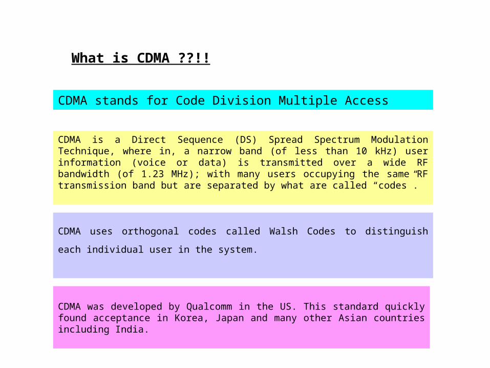
CDMA is a Direct Sequence (DS) Spread Spectrum Modulation Technique, where in, a narrow band (of less than 10 kHz) user information (voice or data) is transmitted over a wide RF bandwidth (of 1.23 MHz); with many users occupying the same RF transmission band but are separated by what are called “codes”.
CDMA uses orthogonal codes called Walsh Codes to distinguish each individual user in the
system.
CDMA was developed by Qualcomm in the US. This standard quickly found acceptance in Korea, Japan and many other Asian countries including India.
What is CDMA ??!!
CDMA stands for Code Division Multiple Access
Time Domain Frequency Domain
t
t n/t
n / t
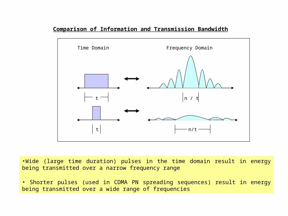
•Wide (large time duration) pulses in the time domain result in energy being transmitted over a narrow frequency range
• Shorter pulses (used in CDMA PN spreading sequences) result in energy being transmitted over a wide range of frequencies
Comparison of Information and Transmission Bandwidth
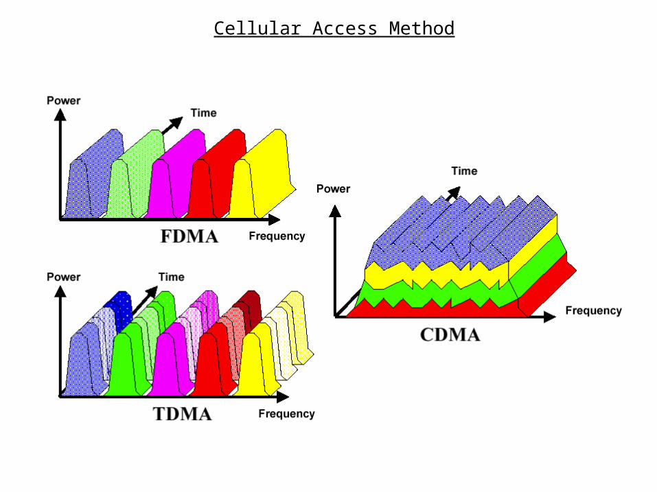
Cellular Access Method
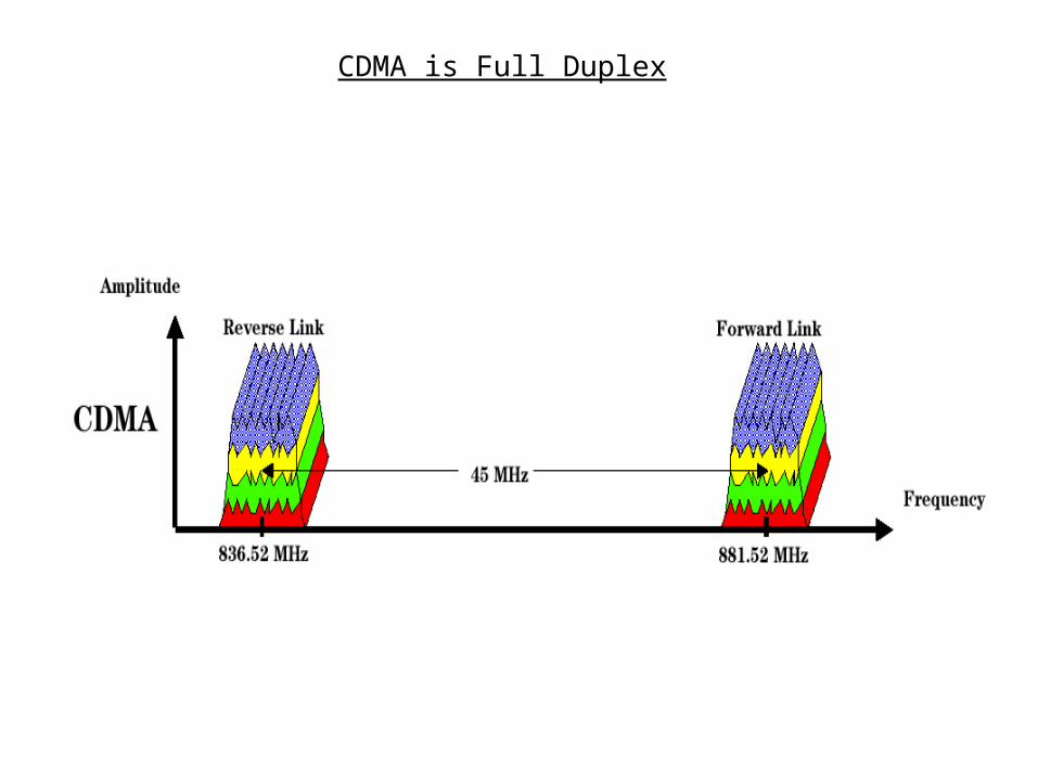
CDMA is Full Duplex
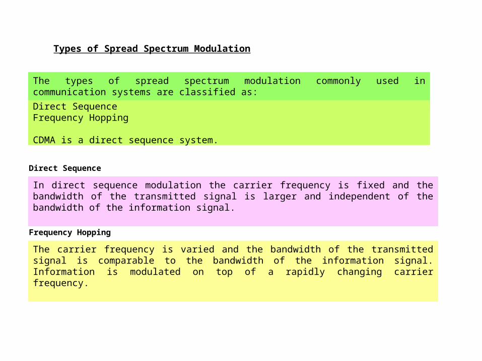
Types of Spread Spectrum Modulation
The types of spread spectrum modulation commonly used in communication systems are classified as:
Direct Sequence Frequency Hopping
CDMA is a direct sequence system.
In direct sequence modulation the carrier frequency is fixed and the bandwidth of the transmitted signal is larger and independent of the bandwidth of the information signal.
The carrier frequency is varied and the bandwidth of the transmitted signal is comparable to the bandwidth of the information signal. Information is modulated on top of a rapidly changing carrier frequency.
Frequency Hopping
Direct Sequence
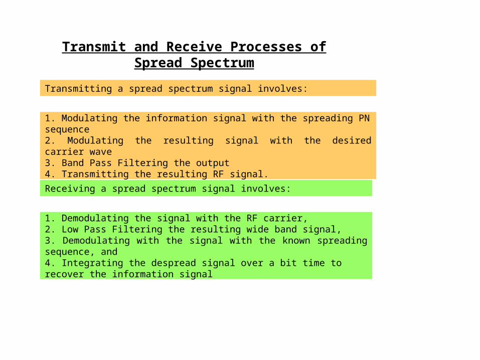
Transmitting a spread spectrum signal involves:
1. Modulating the information signal with the spreading PN sequence 2. Modulating the resulting signal with the desired carrier wave 3. Band Pass Filtering the output4. Transmitting the resulting RF signal.
Receiving a spread spectrum signal involves:
1. Demodulating the signal with the RF carrier, 2. Low Pass Filtering the resulting wide band signal, 3. Demodulating with the signal with the known spreading sequence, and 4. Integrating the de spread signal over a bit time to recover the information signal
Transmit and Receive Processes of Spread Spectrum
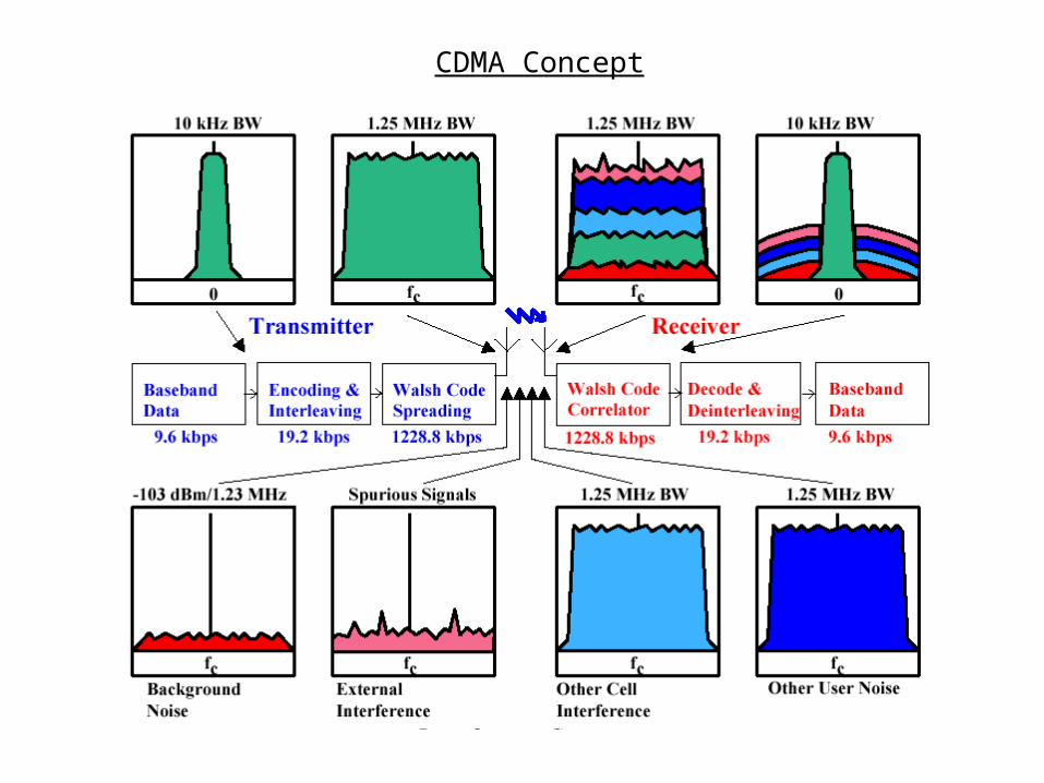
CDMA Concept

RSL
_ _ _ Wide band Noise Floor
…… Narrow band Noise Floor
-40
-60
-80
-100
-120
Power(in dBm)
Distance in Miles
1 4 8 12 16 20 24 28 32
Noise in Narrow Band and Spread Spectrum Communication Systems
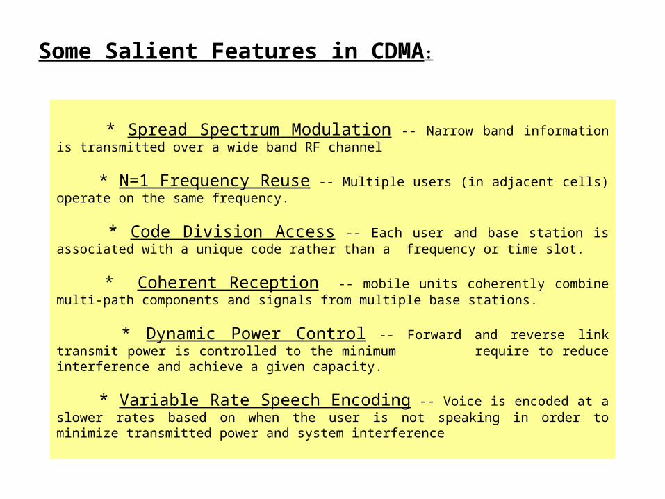
* Spread Spectrum Modulation -- Narrow band information is transmitted over a wide band RF channel
* N=1 Frequency Reuse -- Multiple users (in adjacent cells) operate on the same frequency.
* Code Division Access -- Each user and base station is associated with a unique code rather than a frequency or time slot.
* Coherent Reception -- mobile units coherently combine multi-path components and signals from multiple base stations.
* Dynamic Power Control -- Forward and reverse link transmit power is controlled to the minimum require to reduce interference and achieve a given capacity.
* Variable Rate Speech Encoding -- Voice is encoded at a slower rates based on when the user is not speaking in order to minimize transmitted power and system interference
Some Salient Features in CDMA:
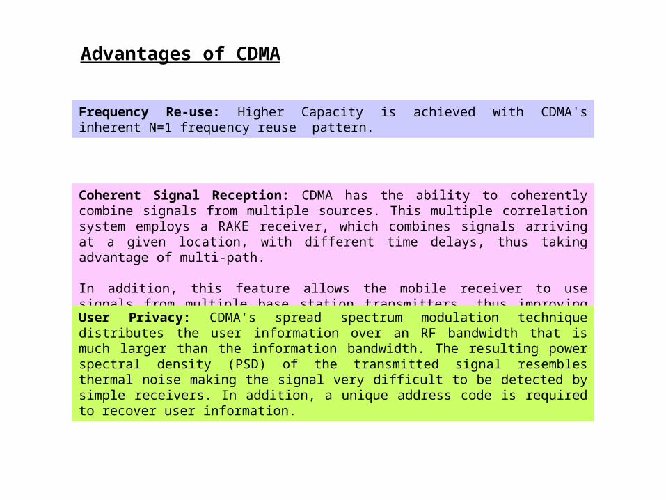
Advantages of CDMA
Coherent Signal Reception: CDMA has the ability to coherently combine signals from multiple sources. This multiple correlation system employs a RAKE receiver, which combines signals arriving at a given location, with different time delays, thus taking advantage of multi-path.
In addition, this feature allows the mobile receiver to use signals from multiple base station transmitters, thus improving cell boundary performance and minimizing dropped calls.
User Privacy: CDMA's spread spectrum modulation technique distributes the user information over an RF bandwidth that is much larger than the information bandwidth. The resulting power spectral density (PSD) of the transmitted signal resembles thermal noise making the signal very difficult to be detected by simple receivers. In addition, a unique address code is required to recover user information.
Frequency Re-use: Higher Capacity is achieved with CDMA's inherent N=1 frequency reuse pattern.
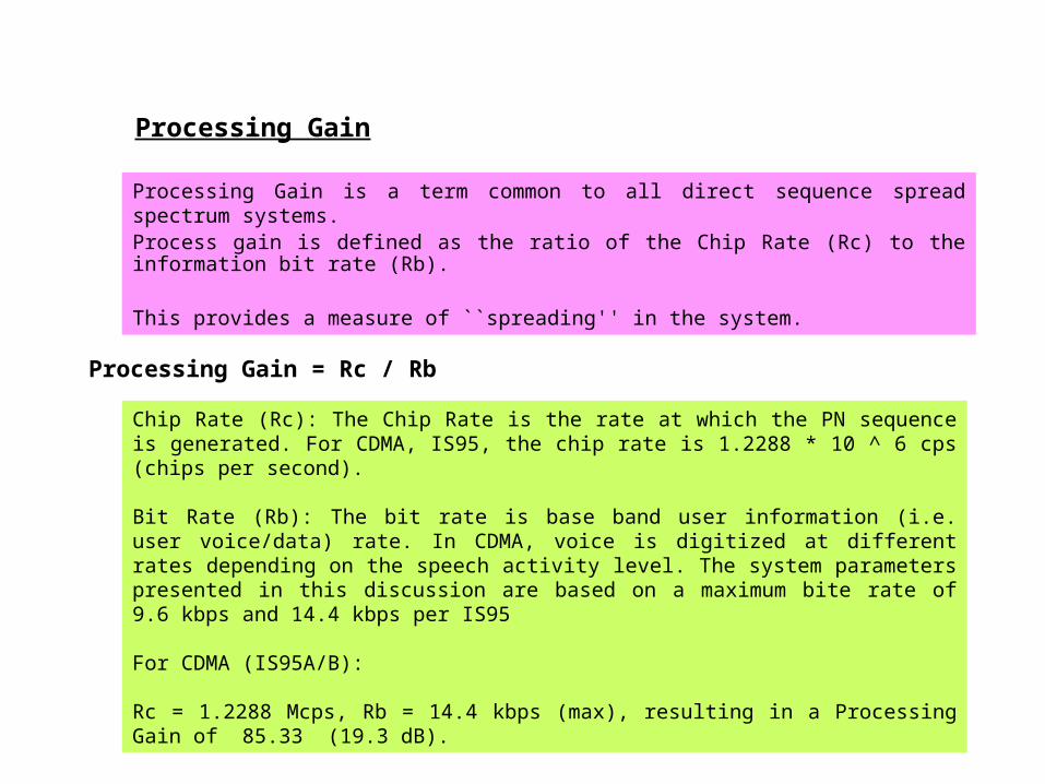
Processing Gain
Chip Rate (Rc): The Chip Rate is the rate at which the PN sequence is generated. For CDMA, IS 95, the chip rate is 1.2288 * 10 ^ 6 cps (chips per second).
Bit Rate (Rb): The bit rate is base band user information (i.e. user voice/data) rate. In CDMA, voice is digitized at different rates depending on the speech activity level. The system parameters presented in this discussion are based on a maximum bite rate of 9.6 kbps and 14.4 kbps per IS 95
For CDMA (IS 95A/B): Rc = 1.2288 Mcps, Rb = 14.4 kbps (max), resulting in a Processing Gain of 85.33 (19.3 dB).
Processing Gain is a term common to all direct sequence spread spectrum systems. Process gain is defined as the ratio of the Chip Rate (Rc) to the information bit rate (Rb).
This provides a measure of ``spreading'' in the system.
Processing Gain = Rc / Rb
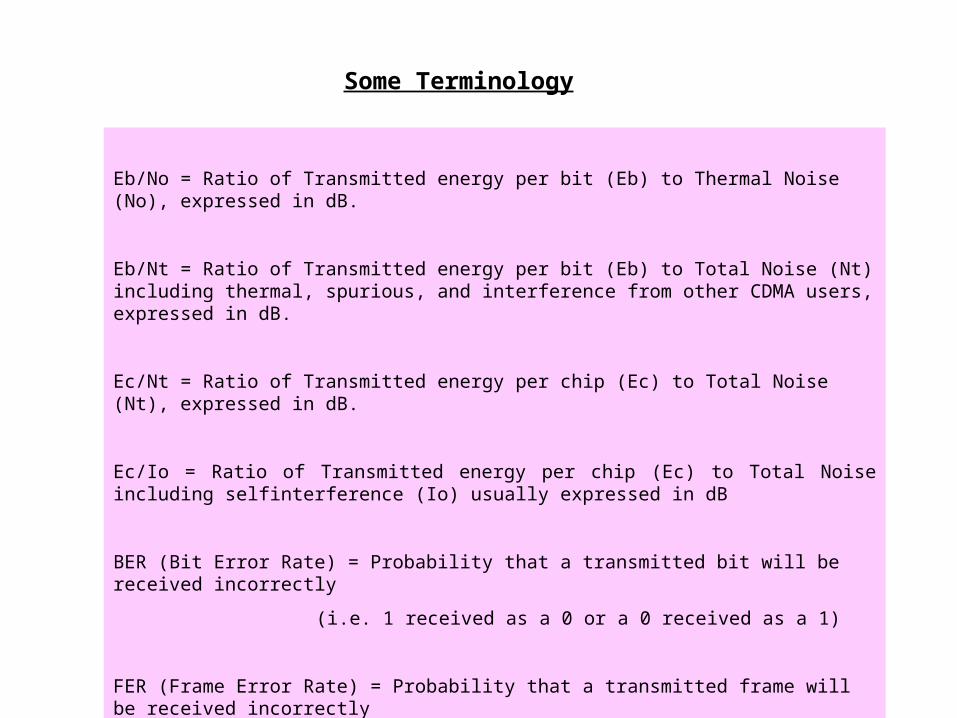
Eb/No = Ratio of Transmitted energy per bit (Eb) to Thermal Noise (No), expressed in dB.
Eb/Nt = Ratio of Transmitted energy per bit (Eb) to Total Noise (Nt) including thermal, spurious, and interference from other CDMA users, expressed in dB.
Ec/Nt = Ratio of Transmitted energy per chip (Ec) to Total Noise (Nt), expressed in dB.
Ec/Io = Ratio of Transmitted energy per chip (Ec) to Total Noise including self interference (Io) usually expressed in dB
BER (Bit Error Rate) = Probability that a transmitted bit will be received incorrectly
(i.e. 1 received as a 0 or a 0 received as a 1)
FER (Frame Error Rate) = Probability that a transmitted frame will be received incorrectly
Some Terminology
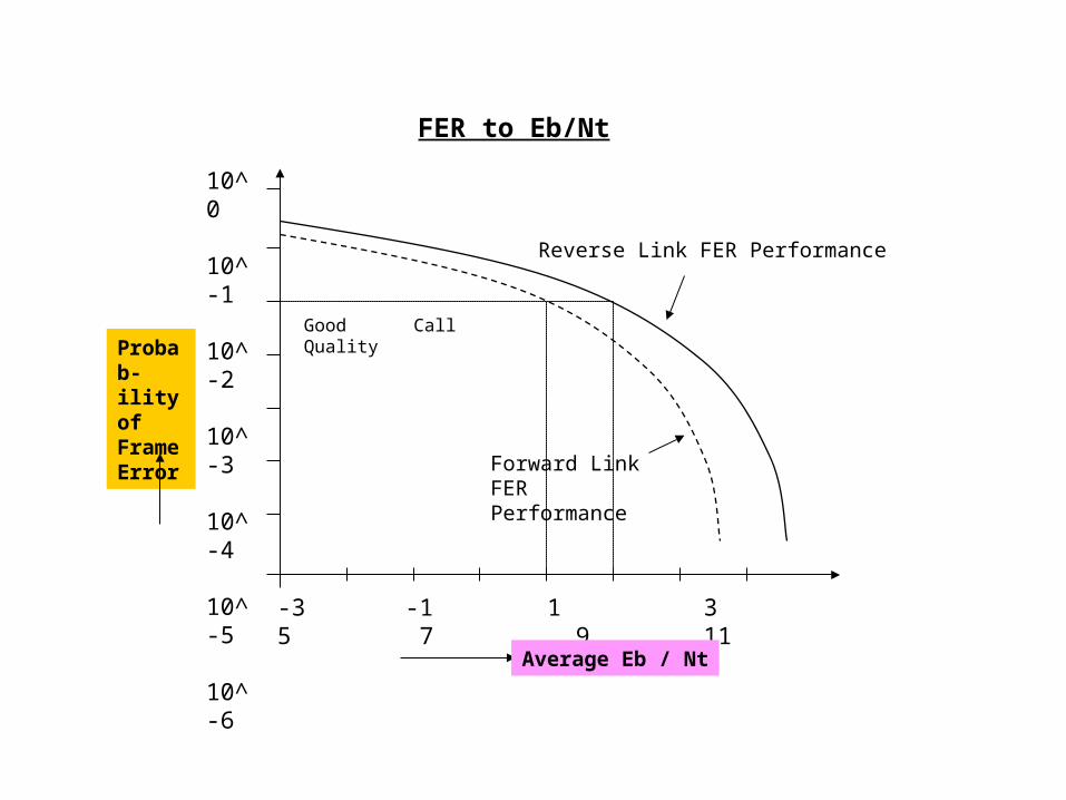
Good Call Quality
10^0
10^-1
10^-2
10^-3
10^-4
10^-5
10^-6
-3 -1 1 3 5 7 9 11
Probab-ility of Frame Error
Average Eb / Nt
Forward Link FER Performance
Reverse Link FER Performance
FER to Eb/Nt
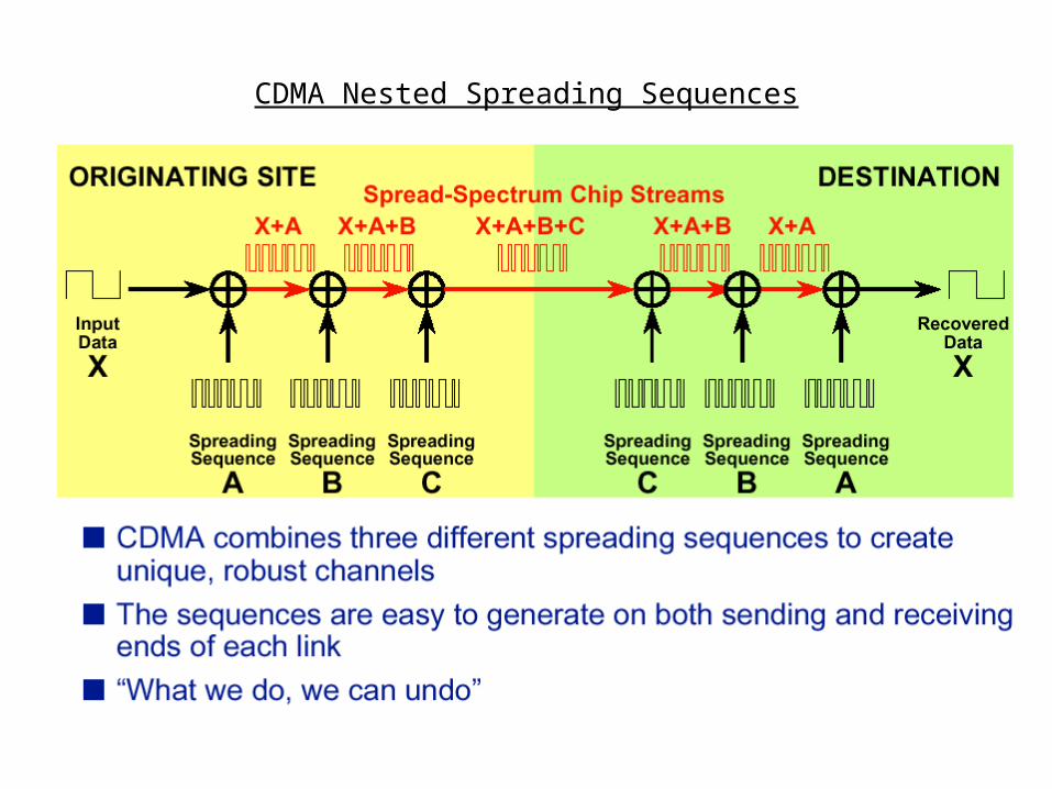
CDMA Nested Spreading Sequences

Summary of Codes
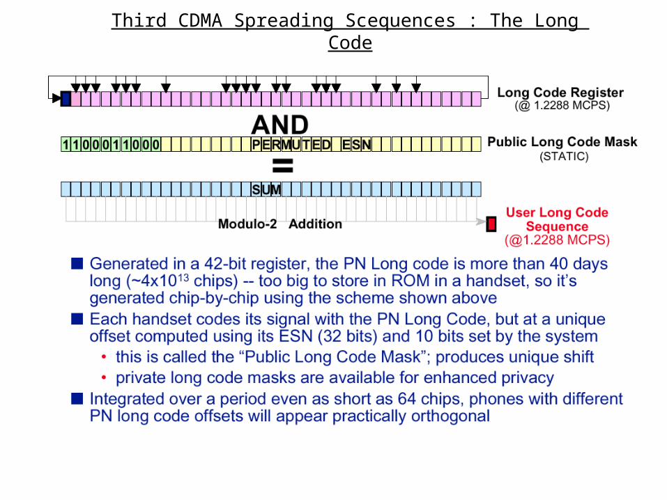
The Long Code is a PN sequence that is 2^42 1 bits (chips) long. It is generated at a rate of 1.2288 Mbps (or Mcps) giving it a period (time before the sequence repeats) of approximately 41.4 days. The long code is used to encrypt user information. Both the base station and the mobile unit have knowledge of this sequence at any given instant in time based on a specified private ``long code mask'' that is exchanged.
PN Long Code
The Short Code is a PN sequence that is 2 ^ 15 bits (chips) in length. This code is generated at 1.2288 Mbps (or Mcps) giving a period of 26.67 ms. This code is used for final spreading of the signal and is transmitted as a reference known as the ``Pilot Sequence'' by the base station. All base stations use the same short code. Base stations are differentiated from one another by transmitting the PN short code at different ``offsets'' in absolute.
PN Short Code
CDMA defines a group of 64 orthogonal sequences, each 64 bits long, known as Walsh Codes. These sequences are also referred to as Wash Functions. These codes are generated at 1.2288 Mbps (Mcps) with a period of approximately 52 µs. These are used to identify users on the forward link. For this reason they are also referred to as either Walsh Channels or TCH. All base stations and mobile users have knowledge of all Walsh codes.
Walsh Codes
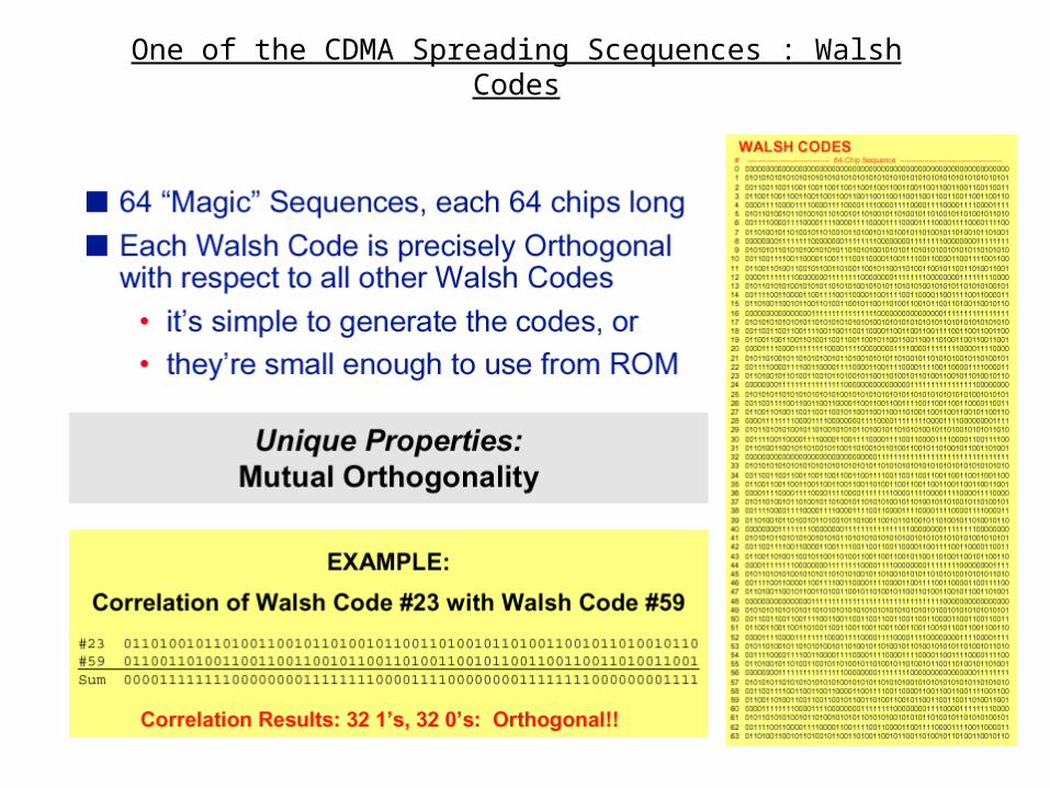
One of the CDMA Spreading Scequences : Walsh Codes
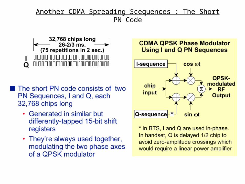
Another CDMA Spreading Scequences : The Short PN Code
Third CDMA Spreading Scequences : The Long Code
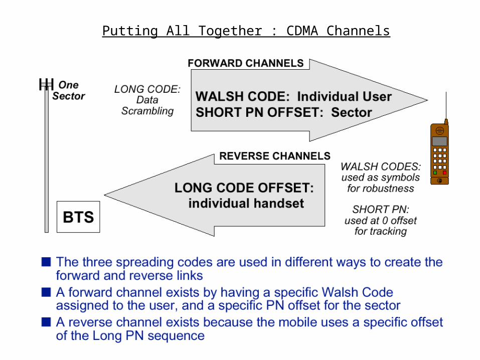
Putting All Together : CDMA Channels
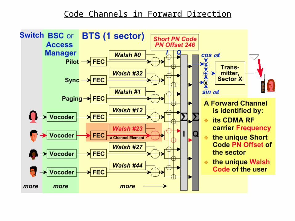
Code Channels in Forward Direction
Functions of CDMA Forward Channels
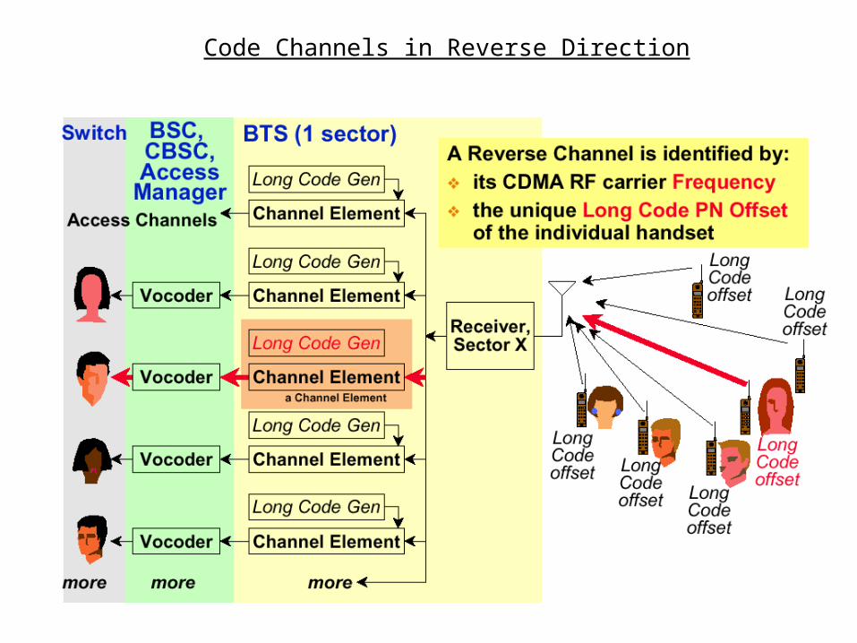
Code Channels in Reverse Direction
Functions of CDMA Reverse Channels
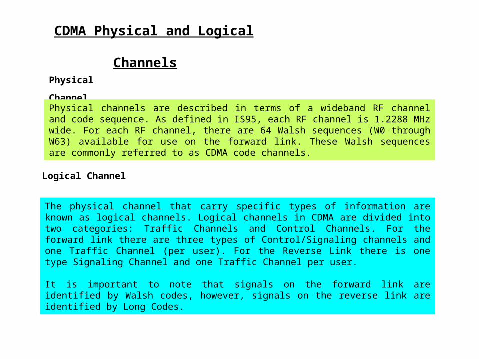
CDMA Physical and Logical Channels Physical Channel Physical channels are described in terms of a wideband RF channel and code sequence. As defined in IS 95, each RF channel is 1.2288 MHz wide. For each RF channel, there are 64 Walsh sequences (W0 through W63) available for use on the forward link. These Walsh sequences are commonly referred to as CDMA code channels.
Logical Channel
The physical channel that carry specific types of information are known as logical channels. Logical channels in CDMA are divided into two categories: Traffic Channels and Control Channels. For the forward link there are three types of Control/Signaling channels and one Traffic Channel (per user). For the Reverse Link there is one type Signaling Channel and one Traffic Channel per user. It is important to note that signals on the forward link are identified by Walsh codes, however, signals on the reverse link are identified by Long Codes.
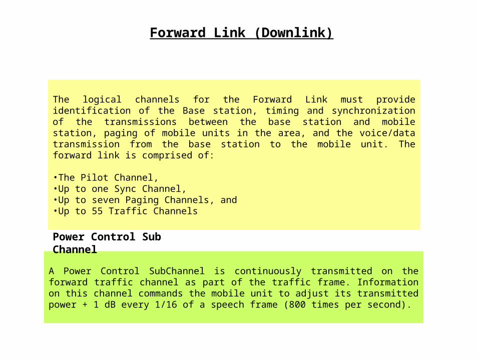
Forward Link (Downlink)
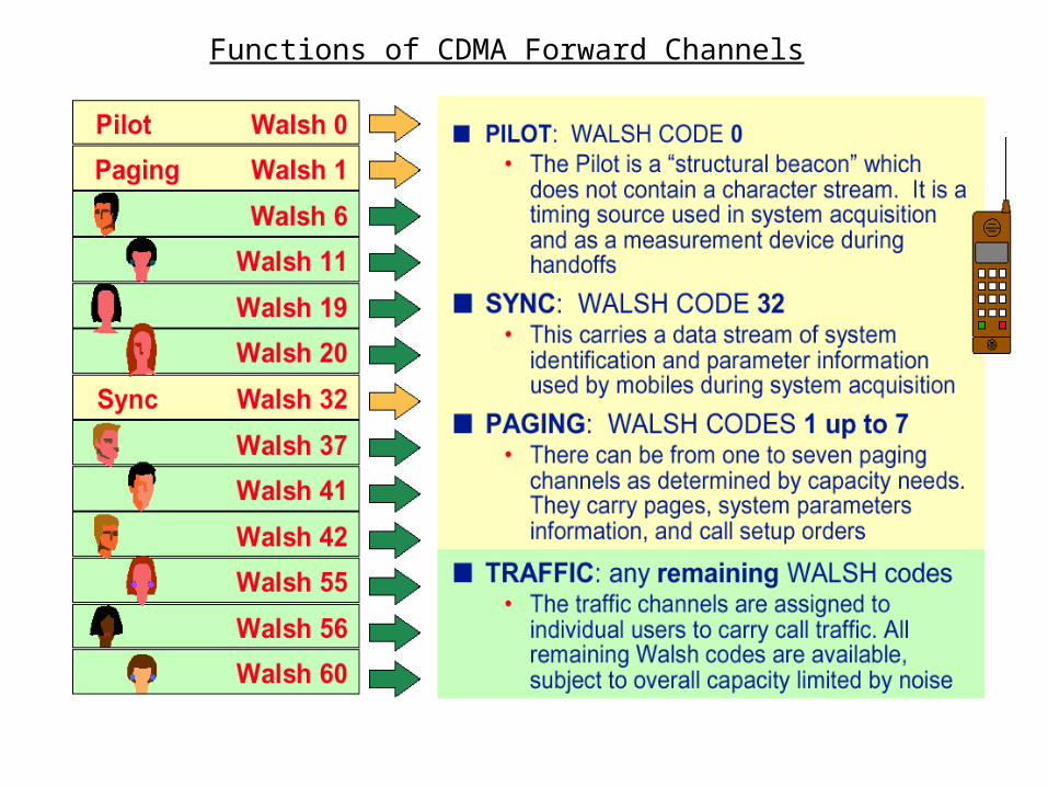
The logical channels for the Forward Link must provide identification of the Base station, timing and synchronization of the transmissions between the base station and mobile station, paging of mobile units in the area, and the voice/data transmission from the base station to the mobile unit. The forward link is comprised of:
•The Pilot Channel, •Up to one Sync Channel, •Up to seven Paging Channels, and •Up to 55 Traffic Channels
A Power Control Sub Channel is continuously transmitted on the forward traffic channel as part of the traffic frame. Information on this channel commands the mobile unit to adjust its transmitted power + 1 dB every 1/16 of a speech frame (800 times per second).
Power Control Sub Channel
The Pilot Channel allows a mobile station to acquire the timing of the Forward Traffic Channel user information. It provides a phase reference for coherent demodulation and provides a means for signal strength comparisons between base stations, which is used to determine when to handoff. It consists of the un-modulated spreading sequences (PN short codes). The Pilot signal is transmitted continuously on Walsh 0 by each CDMA base station at the transmitter (cell/sector) level.
Pilot Channel
Pilot and Sync and Paging Channels
Sync Channel The Synchronization Channel is an encoded, interleaved and modulated spread spectrum signal that is used with the Pilot Channel to acquire initial system time and synchronization. The sync channel is always transmitted on Walsh 32.
The Paging Channel is used for transmission of control information to the mobile. When a mobile is to receive a call it will receive a ``page'' from the base station. Up to seven (7) channels may be configured for paging depending on the expected demand. Page channel messaging to each user takes place in an 80 ms ``slot''. The 80 ms slots are grouped into cycles of 2048 slots (cycle duration 163.84 s) referred to as maximum slot cycles. The base station can limit the maximum slot cycle used by the mobile.
Paging Channel
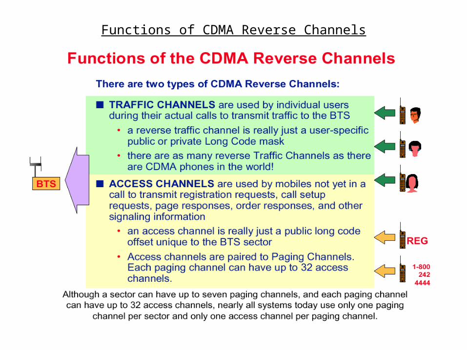
Reverse Link (Uplink)
The logical channel requirements of the reverse link must provide for the identification and access request by the mobile unit to the base stations in the area and the voice/data transmission from the mobile unit to the base station. The reverse link is composed of: •Access Channels and •Traffic Channels. These channels share the same CDMA center frequency on the reverse link (a different frequency is used for forward link transmissions). The total number of channels( max 55) is determined by base station activity. .. The reverse link capability of a given base station is limited by the number of traffic channels assigned (up to 55) and up to seven (7) access channels (correlating to a maximum of 7 paging channels). Note that a mobile does not ``tie up'' an access channel, it only borrows it for a short amount of time.
Access and Traffic Channels
Access Channel The Access Channel is used for the transmission of control information to the base station. When a mobile is to place a call it uses the ``access'' channel to inform the base station. This channel is also used when responding to a ``page''. Each Access Channel is identified by a distinct ``Access Channel Long PN Code ''. An Access Channel is selected randomly by the mobile unit from the total number of access channels available from the serving cell/sector.
Traffic Channel
The Traffic Channel carries all the calls (voice or data signal) from a given base station to all the mobile units active in the coverage area or vice versa. Each user has a dedicated TCH, and corresponding Walsh code, on the down link.
The forward traffic channel message consists of user voice (or data), power control data, and error correction bits. The message is transmitted as a series of traffic frames. The traffic channel may also carry signaling information with or in place of user voice (or data). A Walsh code is assigned by the base station for each Traffic Channel in use.
The Traffic Channel for the reverse link is identical to the forward link Traffic Channel in function and structure. Each traffic channel is identified by a ``User Long PN Code'' which is unique to each CDMA user.
•The coverage provided by CDMA system is not static. As the loading on a given base station changes, the coverage provided by that base station changes inversely. Otherwise stated; just because you have great RF coverage doesn't guarantee good signal.
2. Holes in coverage may result when there is either insufficient or abundant levels of RF. System coverage is measured as the ratio of desired signal to all other signals and that the ratio can be unacceptable regardless of the absolute quantity.
3. CDMA systems allow for the non symmetrical simultaneous processing of a call by multiple base stations. The energy in the forward link is summed to a greater strength than the individual components. The reverse link employs the shotgun effect in that multiple base stations will receive the transmitted signal and the probability that the signal will be acceptable for at least one of them is greatly increased.
4. Traffic engineering in a CDMA system requires that in addition to all of the factors associated with engineering a FDMA or TDMA system, the element of time also be introduced. PN Offset Planning for a CDMA system requires the careful assignment of 512 available time offsets to the cells/sectors in a system
Concepts to be kept in mind for CDMA system Engineering
PN Offset Planning
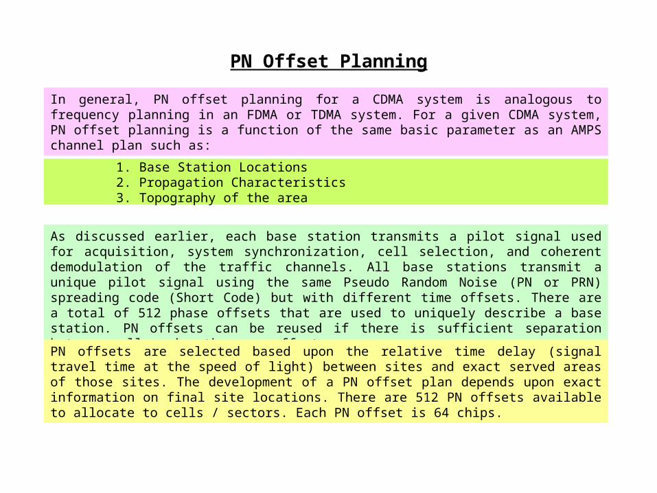
In general, PN offset planning for a CDMA system is analogous to frequency planning in an FDMA or TDMA system. For a given CDMA system, PN offset planning is a function of the same basic parameter as an AMPS channel plan such as:
1. Base Station Locations 2. Propagation Characteristics 3. Topography of the area
As discussed earlier, each base station transmits a pilot signal used for acquisition, system synchronization, cell selection, and coherent demodulation of the traffic channels. All base stations transmit a unique pilot signal using the same Pseudo Random Noise (PN or PRN) spreading code (Short Code) but with different time offsets. There are a total of 512 phase offsets that are used to uniquely describe a base station. PN offsets can be reused if there is sufficient separation between cells using the same offset.
PN offsets are selected based upon the relative time delay (signal travel time at the speed of light) between sites and exact served areas of those sites. The development of a PN offset plan depends upon exact information on final site locations. There are 512 PN offsets available to allocate to cells / sectors. Each PN offset is 64 chips.
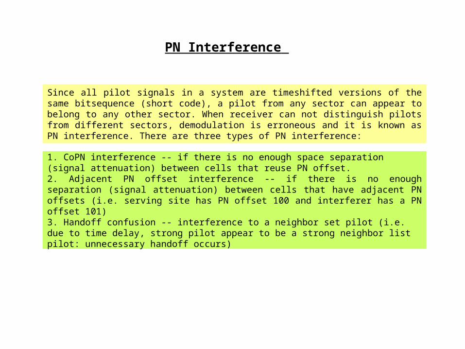
Since all pilot signals in a system are time shifted versions of the same bit sequence (short code), a pilot from any sector can appear to belong to any other sector. When receiver can not distinguish pilots from different sectors, demodulation is erroneous and it is known as PN interference. There are three types of PN interference:
1. Co PN interference -- if there is no enough space separation (signal attenuation) between cells that reuse PN offset. 2. Adjacent PN offset interference -- if there is no enough separation (signal attenuation) between cells that have adjacent PN offsets (i.e. serving site has PN offset 100 and interferer has a PN offset 101) 3. Handoff confusion -- interference to a neighbor set pilot (i.e. due to time delay, strong pilot appear to be a strong neighbor list pilot: unnecessary handoff occurs)
PN Interference
The “Near-Far” Problem and Dynamic Power Control
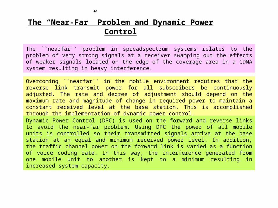
The ``near far'' problem in spread spectrum systems relates to the problem of very strong signals at a receiver swamping out the effects of weaker signals located on the edge of the coverage area in a CDMA system resulting in heavy interference.
Overcoming ``near far'' in the mobile environment requires that the reverse link transmit power for all subscribers be continuously adjusted. The rate and degree of adjustment should depend on the maximum rate and magnitude of change in required power to maintain a constant received level at the base station. This is accomplished through the implementation of dynamic power control.
Dynamic Power Control (DPC) is used on the forward and reverse links to avoid the near-far problem. Using DPC the power of all mobile units is controlled so their transmitted signals arrive at the base station at an equal and minimum received power level. In addition, the traffic channel power on the forward link is varied as a function of voice coding rate. In this way, the interference generated from one mobile unit to another is kept to a minimum resulting in increased system capacity.
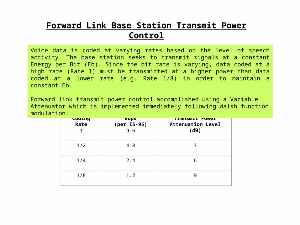
Voice Coding Rate
Data Rate (Rb) kbps(per IS-95)
Base Station Transmit Power Attenuation Level
(dB)1
9.6 0
1/2
4.8 3
1/4
2.4 6
1/8
1.2 9
Forward Link Base Station Transmit Power Control
Voice data is coded at varying rates based on the level of speech activity. The base station seeks to transmit signals at a constant Energy per Bit (Eb). Since the bit rate is varying, data coded at a high rate (Rate 1) must be transmitted at a higher power than data coded at a lower rate (e.g. Rate 1/8) in order to maintain a constant Eb. Forward link transmit power control accomplished using a Variable Attenuator which is implemented immediately following Walsh function modulation.
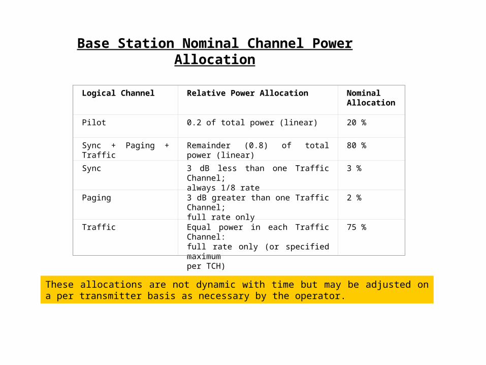
Base Station Nominal Channel Power Allocation
Logical Channel Relative Power Allocation Nominal Allocation
Pilot 0.2 of total power (linear) 20 %
Sync + Paging + Traffic Remainder (0.8) of total power (linear) 80 %
Sync
3 dB less than one Traffic Channel; always 1/8 rate
3 %
Paging
3 dB greater than one Traffic Channel; full rate only
2 %
Traffic
Equal power in each Traffic Channel: full rate only (or specified maximum per TCH)
75 %
These allocations are not dynamic with time but may be adjusted on a per transmitter basis as necessary by the operator.
CDMA Capacity
CDMA technology offers a significant capacity advantage over other multiple access systems. The capacity of FDMA and TDMA systems is limited by the finite amount of spectrum allocated. CDMA is different in that many users operate on a single wideband RF carrier. This carrier frequency may be reused by the adjacent cell (N=1 reuse). CDMA capacity is only interference limited, therefore any reduction in interference converts directly and linearly into an increase in capacity
Interference is introduced from several sources including: Same cell mobile users, Adjacent cell mobile users, Adjacent cell base stations, as well as Thermal and spurious noise.
CDMA employs several techniques to reduce these interference sources including: •Suppressing or squelching transmissions during quiet periods of each speaker. •Using sectored base station antennas. •Dynamic power control to keep transmit levels to the minimum required to close the link.
Coverage and Capacity Relationship
There is an inverse relationship between the coverage area of a given cell and the loading on that cell due to a rising of the noise floor induced by the users on that site. This phenomena results in a ``breathing'' and a ``self regulating'' communication system. The average required capacity of a given base station has to be estimated at the time of design so as to predict both the coverage it will provide and the interference it will introduce at a given average loading.
On the system level, the design of a network that will provide seamless coverage at 70% theoretical loading will require a greater number of cells spaced closer together than a network designed to operate at 50% theoretical loading.
A sensitivity analysis will provide the design engineer with an idea of the extent system performance will change for increases and decreases in instantaneous traffic loading. This analysis is essentially an overlay of the coverage provided at the maximum anticipated operating level placed atop the coverage provided at an average anticipated operating levels. By performing several iterations at various levels, an engineer will be able to determine the maximum average loading the system can sustain and still meet the design coverage objectives.
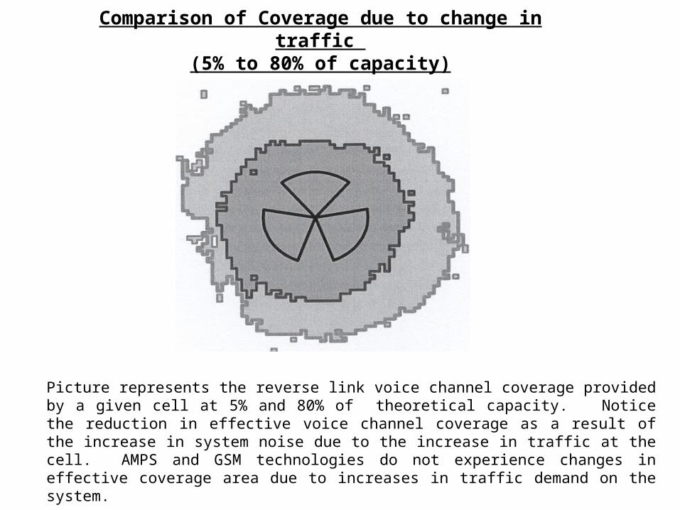
Comparison of Coverage due to change in traffic (5% to 80% of capacity)
Picture represents the reverse link voice channel coverage provided by a given cell at 5% and 80% of theoretical capacity. Notice the reduction in effective voice channel coverage as a result of the increase in system noise due to the increase in traffic at the cell. AMPS and GSM technologies do not experience changes in effective coverage area due to increases in traffic demand on the system.
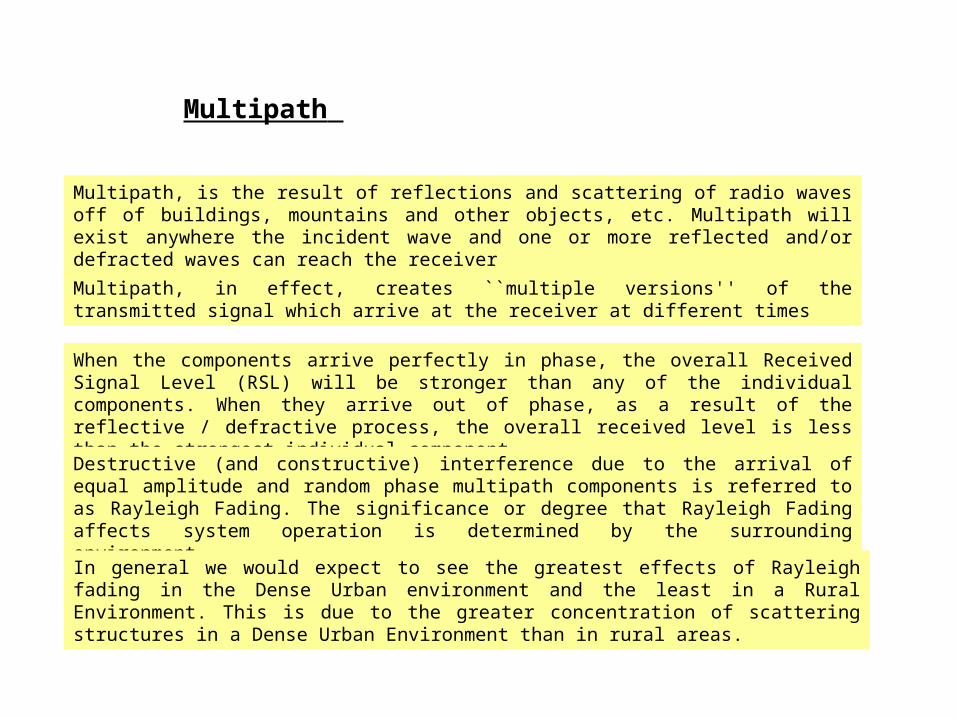
Multipath, is the result of reflections and scattering of radio waves off of buildings, mountains and other objects, etc. Multipath will exist anywhere the incident wave and one or more reflected and/or defracted waves can reach the receiver
Multipath, in effect, creates ``multiple versions'' of the transmitted signal which arrive at the receiver at different times
When the components arrive perfectly in phase, the overall Received Signal Level (RSL) will be stronger than any of the individual components. When they arrive out of phase, as a result of the reflective / defractive process, the overall received level is less than the strongest individual component.
Destructive (and constructive) interference due to the arrival of equal amplitude and random phase multipath components is referred to as Rayleigh Fading. The significance or degree that Rayleigh Fading affects system operation is determined by the surrounding environment.
In general we would expect to see the greatest effects of Rayleigh fading in the Dense Urban environment and the least in a Rural Environment. This is due to the greater concentration of scattering structures in a Dense Urban Environment than in rural areas.
Multipath

Destructive Interference due to Multipath
Relative Amplitude
Time
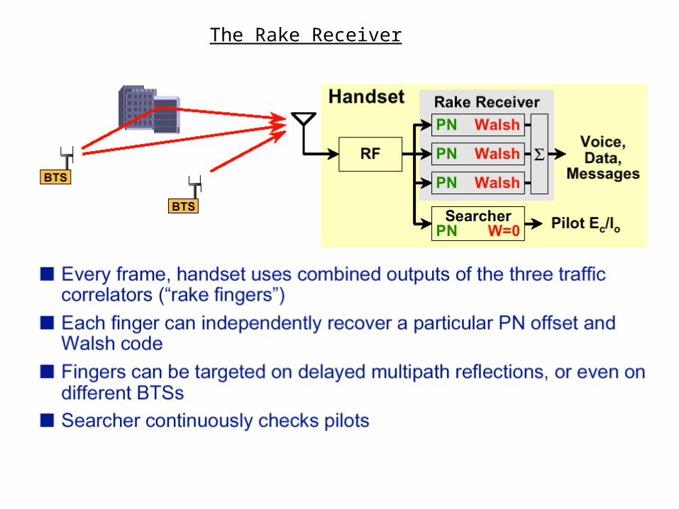
The Rake Receiver
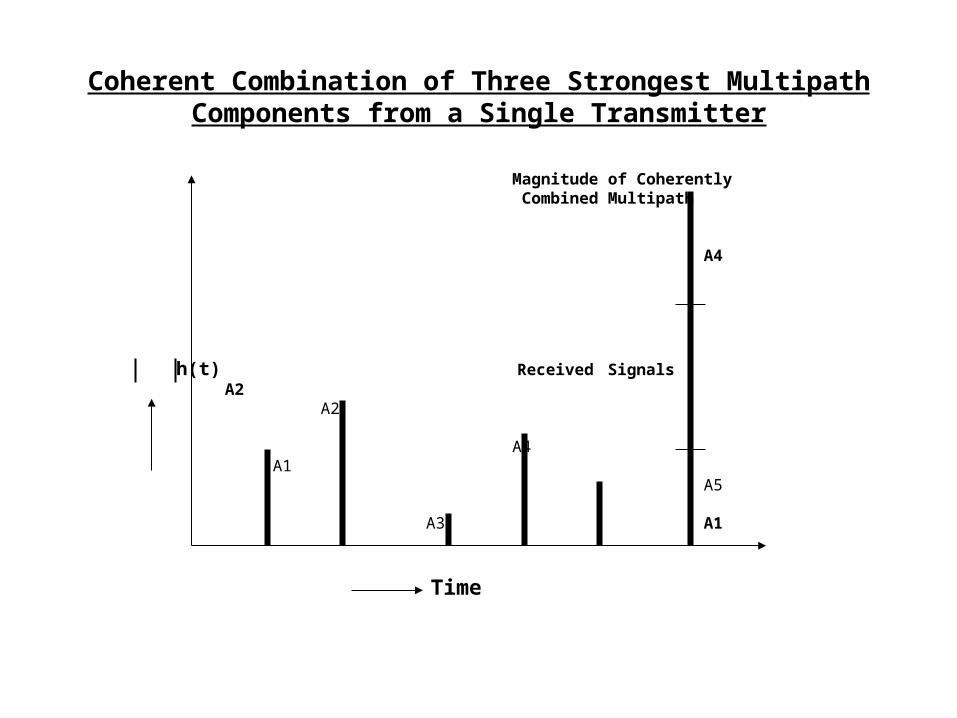
Magnitude of Coherently Combined Multipath
A4
h(t) Received Signals A2A2
A4
A1 A5
A3 A1
Coherent Combination of Three Strongest Multipath Components from a Single Transmitter
Time
Effects of Multipath on FDMA, TDMA, and CDMA
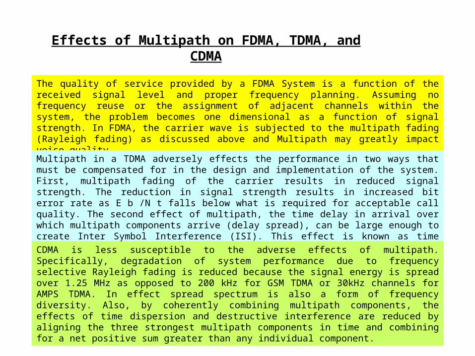
The quality of service provided by a FDMA System is a function of the received signal level and proper frequency planning. Assuming no frequency reuse or the assignment of adjacent channels within the system, the problem becomes one dimensional as a function of signal strength. In FDMA, the carrier wave is subjected to the multipath fading (Rayleigh fading) as discussed above and Multipath may greatly impact voice quality.
Multipath in a TDMA adversely effects the performance in two ways that must be compensated for in the design and implementation of the system. First, multipath fading of the carrier results in reduced signal strength. The reduction in signal strength results in increased bit error rate as E b /N t falls below what is required for acceptable call quality. The second effect of multipath, the time delay in arrival over which multipath components arrive (delay spread), can be large enough to create Inter Symbol Interference (ISI). This effect is known as time dispersion. ISI may result in false 1's when a zero is sent or visa versa.
CDMA is less susceptible to the adverse effects of multipath. Specifically, degradation of system performance due to frequency selective Rayleigh fading is reduced because the signal energy is spread over 1.25 MHz as opposed to 200 kHz for GSM TDMA or 30kHz channels for AMPS TDMA. In effect spread spectrum is also a form of frequency diversity. Also, by coherently combining multipath components, the effects of time dispersion and destructive interference are reduced by aligning the three strongest multipath components in time and combining for a net positive sum greater than any individual component.
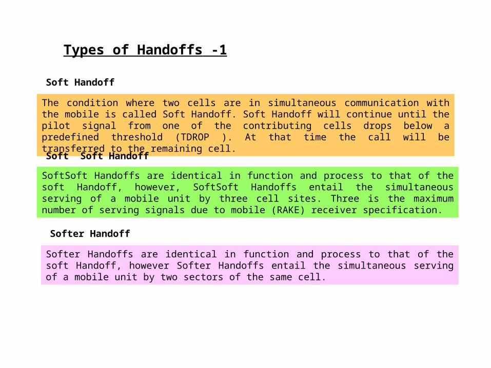
Types of Handoffs -1
The condition where two cells are in simultaneous communication with the mobile is called Soft Handoff. Soft Handoff will continue until the pilot signal from one of the contributing cells drops below a predefined threshold (TDROP ). At that time the call will be transferred to the remaining cell.
Soft Handoff
Soft Soft Handoffs are identical in function and process to that of the soft Handoff, however, Soft Soft Handoffs entail the simultaneous serving of a mobile unit by three cell sites. Three is the maximum number of serving signals due to mobile (RAKE) receiver specification.
Soft Soft Handoff
Softer Handoff
Softer Handoffs are identical in function and process to that of the soft Handoff, however Softer Handoffs entail the simultaneous serving of a mobile unit by two sectors of the same cell.

Types of Handoffs -2
Soft Softer Handoff
Soft Softer Handoffs are identical in function and process to that of the Soft Handoff, however, Soft Softer Handoffs are the simultaneous serving of a mobile station by the original sector, an adjacent sector, and an adjacent or neighboring cell.
Hard Handoff
A hard Handoff occurs when a CDMA call is transferred from one base station to another base station transmitting on a different carrier frequency. Hard Handoff is analogous to the Handoff procedure that takes place in standard AMPS Cellular.
CDMA to Analog Handoff
If there are no CDMA channels to Handoff to, then the call would be handed off to an available analog channel at the serving base station and switched to the analog mode of processing. From that point on, the call will be handled as any other analog call at that base station.
The mobile unit will initially seek to perform a soft Handoff. If the cellular network cannot perform a soft Handoff, a hard Handoff is necessary
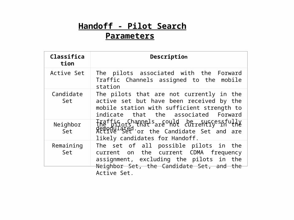
Classification Description
Active Set The pilots associated with the Forward Traffic Channels assigned to the mobile station
Candidate Set The pilots that are not currently in the active set but have been received by the mobile station with sufficient strength to indicate that the associated Forward Traffic Channels could be successfully demodulated.
Neighbor Set The pilots that are not currently in the Active Set or the Candidate Set and are likely candidates for Handoff.
Remaining Set The set of all possible pilots in the current on the current CDMA frequency assignment, excluding the pilots in the Neighbor Set, the Candidate Set, and the Active Set.
Handoff - Pilot Search Parameters
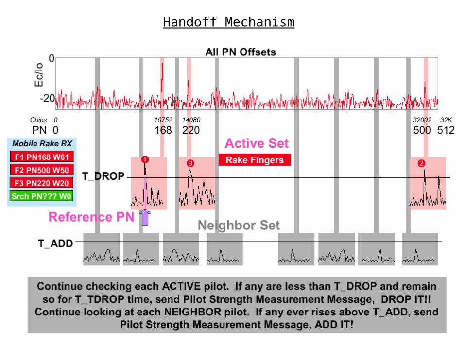
Handoff Mechanism
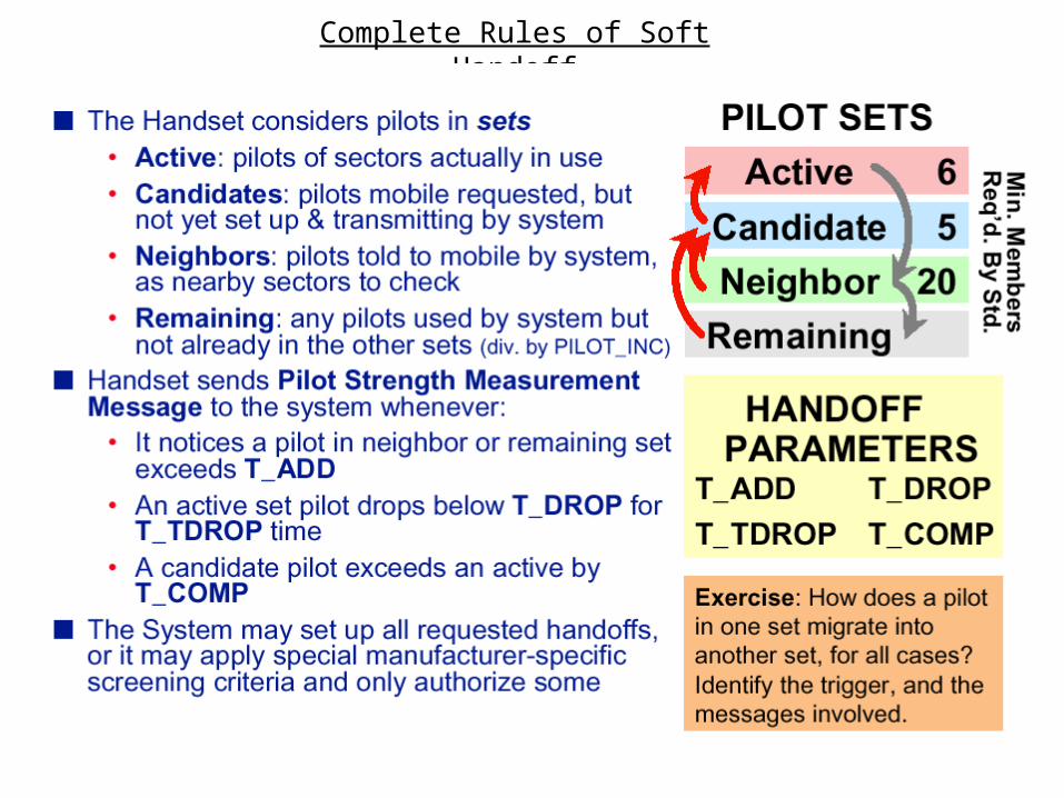
Complete Rules of Soft Handoff
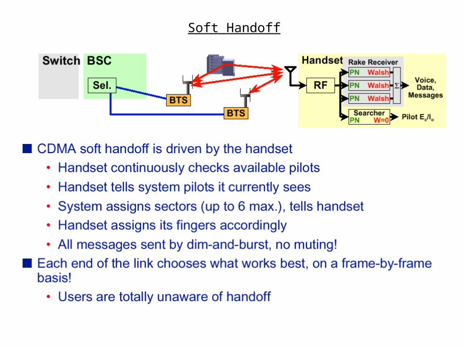
Soft Handoff
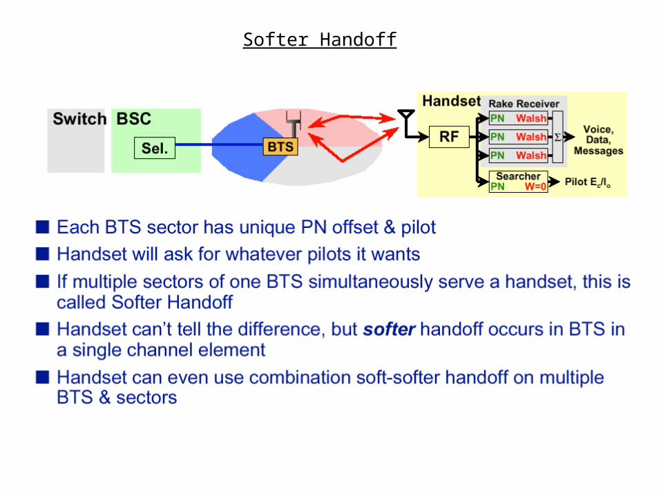
Softer Handoff
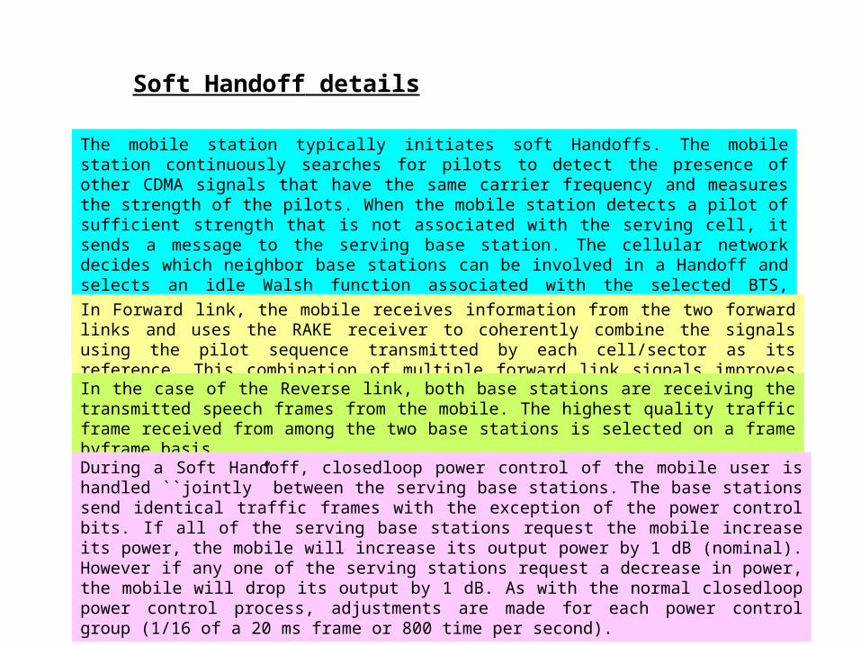
Soft Handoff details
The mobile station typically initiates soft Handoffs. The mobile station continuously searches for pilots to detect the presence of other CDMA signals that have the same carrier frequency and measures the strength of the pilots. When the mobile station detects a pilot of sufficient strength that is not associated with the serving cell, it sends a message to the serving base station. The cellular network decides which neighbor base stations can be involved in a Handoff and selects an idle Walsh function associated with the selected BTS, effectively selecting a traffic channel. The selected BTS is given the mobile's long code mask. The serving base station is directed to send the mobile a message to initiate Soft Handoff.
In Forward link, the mobile receives information from the two forward links and uses the RAKE receiver to coherently combine the signals using the pilot sequence transmitted by each cell/sector as its reference. This combination of multiple forward link signals improves overall link performance.
In the case of the Reverse link, both base stations are receiving the transmitted speech frames from the mobile. The highest quality traffic frame received from among the two base stations is selected on a frame by frame basis.
During a Soft Handoff, closed loop power control of the mobile user is handled ``jointly” between the serving base stations. The base stations send identical traffic frames with the exception of the power control bits. If all of the serving base stations request the mobile increase its power, the mobile will increase its output power by 1 dB (nominal). However if any one of the serving stations request a decrease in power, the mobile will drop its output by 1 dB. As with the normal closed loop power control process, adjustments are made for each power control group (1/16 of a 20 ms frame or 800 time per second).
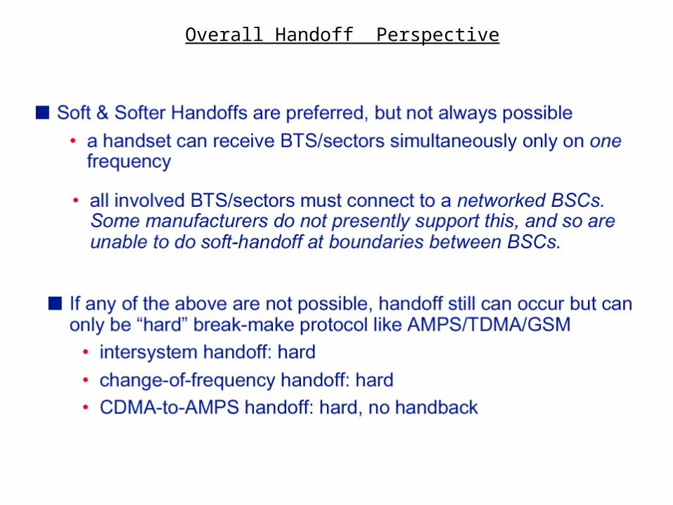
Overall Handoff Perspective
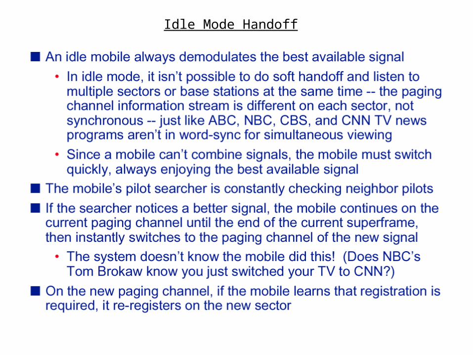
Idle Mode Handoff
CDMA Call Processing
The following is an example of a cellular call: set-up, progress and termination in a CDMA system. The example describes:
•Initial system access •Call initiation and setup, •Soft Handoff, and Call termination.
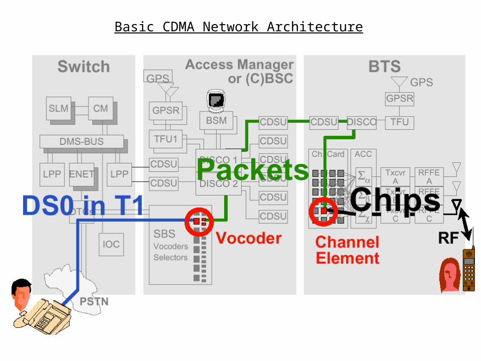
Basic CDMA Network Architecture
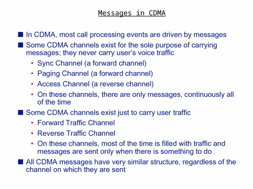
Messages in CDMA
Initial System Access
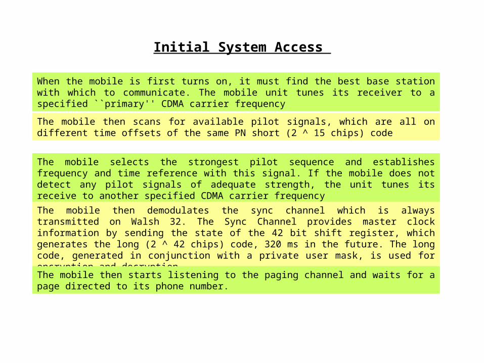
When the mobile is first turns on, it must find the best base station with which to communicate. The mobile unit tunes its receiver to a specified ``primary'' CDMA carrier frequency
The mobile then scans for available pilot signals, which are all on different time offsets of the same PN short (2 ^ 15 chips) code
The mobile selects the strongest pilot sequence and establishes frequency and time reference with this signal. If the mobile does not detect any pilot signals of adequate strength, the unit tunes its receive to another specified CDMA carrier frequency
The mobile then demodulates the sync channel which is always transmitted on Walsh 32. The Sync Channel provides master clock information by sending the state of the 42 bit shift register, which generates the long (2 ^ 42 chips) code, 320 ms in the future. The long code, generated in conjunction with a private user mask, is used for encryption and decryption
The mobile then starts listening to the paging channel and waits for a page directed to its phone number.
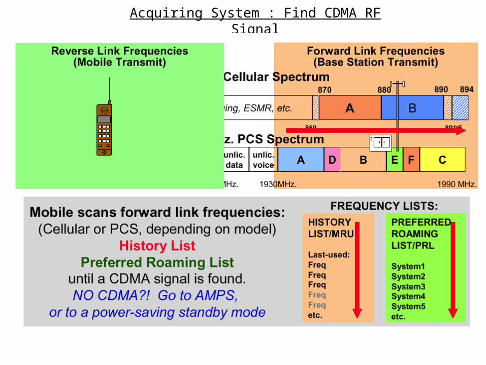
Acquiring System : Find CDMA RF Signal
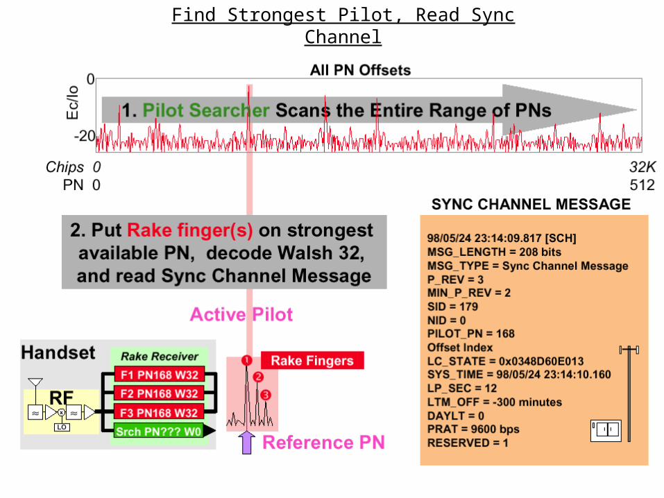
Find Strongest Pilot, Read Sync Channel
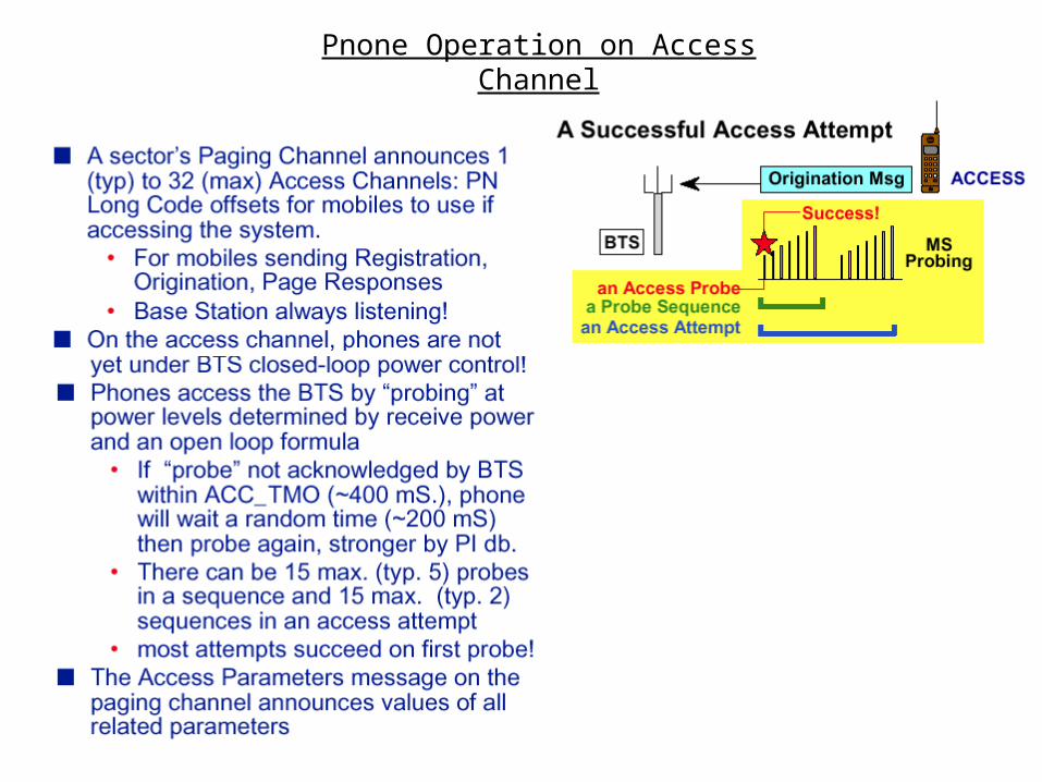
Pnone Operation on Access Channel
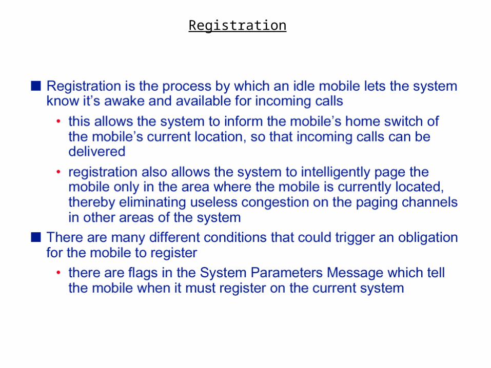
Registration
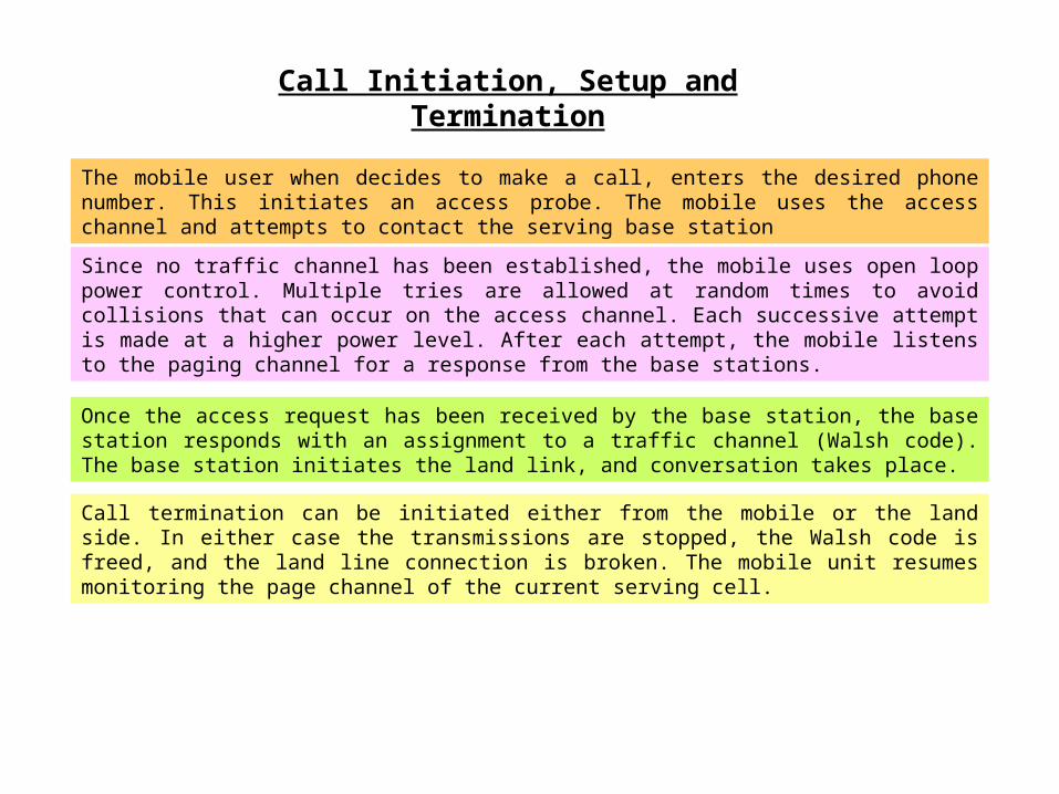
Call Initiation, Setup and Termination
The mobile user when decides to make a call, enters the desired phone number. This initiates an access probe. The mobile uses the access channel and attempts to contact the serving base station
Since no traffic channel has been established, the mobile uses open loop power control. Multiple tries are allowed at random times to avoid collisions that can occur on the access channel. Each successive attempt is made at a higher power level. After each attempt, the mobile listens to the paging channel for a response from the base stations.
Once the access request has been received by the base station, the base station responds with an assignment to a traffic channel (Walsh code). The base station initiates the land link, and conversation takes place.
Call termination can be initiated either from the mobile or the land side. In either case the transmissions are stopped, the Walsh code is freed, and the land line connection is broken. The mobile unit resumes monitoring the page channel of the current serving cell.
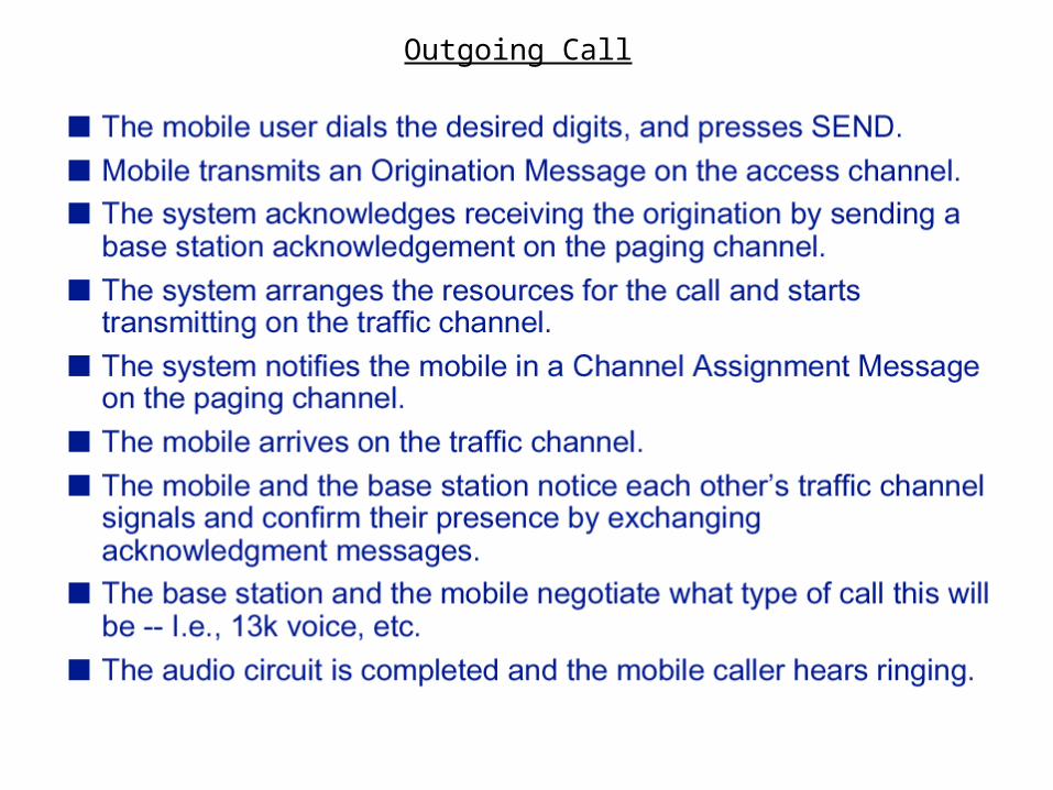
Outgoing Call
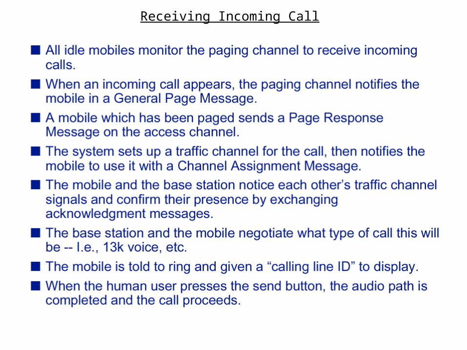
Receiving Incoming Call
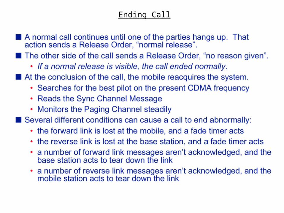
Ending Call


