COMBINED CYCLE JOURNAL, Third Quarter 2008 89 COMBUSTION DYNAMICS MONITORING SPECIAL ISSUE: OUTAGE HANDBOOK M ost gas-turbine (GT) users familiar with dry low-emissions (DLE) com- bustion systems have heard the acronym CDMS, short for combustion dynamics monitor- ing system. This certainly sounds important, and it is. But the term “combus- tion dynamics” and what it means to GT owner/opera- tors often is not well under- stood at the plant level. Dr Timothy Lieuwen, PE, associate professor, School of Aerospace Engi- neering, Georgia Institute of Technology, knows this and devotes much of his time help- ing users understand in simple terms what combustion dynamics is, why it happens, how to recognize it, how to deal with it, etc. Lieuwen is a beacon in a graying industry, a bright engineer, not yet 40, who is as comfortable in a powerplant as he is in a classroom or laboratory. Think of Tim, the name he prefers, as the electric-power generation sector’s “Indiana Jones.” CD is difficult to under- stand by just speaking to industry colleagues because you get snippets of knowl- edge that are hard to con- nect not knowing what the finished puzzle looks like. The editors have had access to, and have been helped by, several of the industry’s subject-matter experts—in- cluding EPRI’s Len Angello, PSM’s Jesse Sewell, PPL’s Mike Magnan, GTE’s Mar- cus Turner, and Siemens Energy’s Phil Karwowski— but the fog didn’t clear until they attended Lieuwen’s “short course.” “Combustion Instabili- ties in Gas-Turbine-Based Power Plants,” was a one- day workshop that pre- ceded the 2008 Gas Turbine Users Symposium sponsored by ASME’s International Gas Turbine Institute’s (IGTI), which co-locates with the annual Turbomachinery Symposium in Houston. That Lieuwen is dedi- cated to making the subject matter understandable is evident in the course title, where he substituted “insta- bilities,” a term virtually everyone understands, for “dynamics.” He uses the terms “oscillations” and “pulsations” as well—two words more descriptive to most people than “dynam- ics.” Perhaps even more descriptive synonyms are “humming,” “rumble,” and “screech”—the sounds you hear when combustion approaches insta- bility. There was just enough combus- tion physics and math in the course to allow an understanding of the science and how engineers apply it to prevent the damaging effects of dynamics on hardware. Those who wanted more were referred to a ref- erence work on the subject edited by Lieuwen and Vigor Yang (Sidebar 1). Most disappointing about the workshop was that only two of the 22 participants represented the electric power industry; 14 were from com- panies in the oil, gas, and chemical sectors. Even turbine OEMs and third-party parts suppliers outnum- bered the power producers two to one. Certainly an opportunity lost for electric-power generators. Course outline. Lieuwen divided the workshop material into six segments; a break after each segment enabled group discussion and allowed time to answer specific questions. The course outline follows: n Key factors influencing GT com- bustor performance. n Combustion instabilities: What they are; historical experience. n Conditions conducive to instabili- ties and the influence of fuel com- position. n Strategies for eliminating insta- bilities. n How to monitor instabili- ties. n Additional uses for data gathered while monitoring the combustion process. In his introductory remarks, Lieuwen empha- sized that dynamics are not unique to DLE combustion systems, or even to GTs. They occur in many combus- tion processes—including boilers, furnaces, etc. He would later show in the historical-experience seg- ment of the course how ram- jet, afterburner, and rocket components were routinely destroyed by CD until engi- neers were able to run thou- sands of full-scale tests to understand what was hap- pening and how to mitigate the damage. CDMS helps prevent forced outages, tune engine after overhaul Learned at IGTI’s Workshop “Combustion Dynamics in Gas Turbine Powerplants” Next meeting: Sept 14-17, 2009 George R Brown Convention Center, Houston ASME International Gas Turbine Institute http://igti.asme.org ASME International Gas Turbine Institute http://igti.asme.org Lieuwen
Most gas- turbine (GT) users familiar with dry low-emissions (DLE) com-bustion systems have
heard the acronym CDMS, short for combustion dynamics monitor-ing system. This certainly sounds important, and it is. But the term “combus-tion dynamics” and what it means to GT owner/opera-tors often is not well under-stood at the plant level.
Dr Timothy Lieuwen, PE, associate professor, School of Aerospace Engi-neering, Georgia Institute of Technology, knows this and devotes much of his time help-ing users understand in simple terms what combustion dynamics is, why it happens, how to recognize it, how to deal with it, etc. Lieuwen is a beacon in a graying industry, a bright engineer, not yet 40, who is as comfortable in a powerplant as he is in a classroom or laboratory. Think of Tim, the name he prefers, as the electric-power generation sector’s “Indiana Jones.”
CD is difficult to under-stand by just speaking to industry colleagues because you get snippets of knowl-edge that are hard to con-nect not knowing what the finished puzzle looks like. The editors have had access to, and have been helped by, several of the industry’s subject-matter experts—in-cluding EPRI’s Len Angello, PSM’s Jesse Sewell, PPL’s Mike Magnan, GTE’s Mar-cus Turner, and Siemens Energy’s Phil Karwowski—but the fog didn’t clear until they attended Lieuwen’s “short course.”
“Combustion Instabili-ties in Gas-Turbine-Based Power Plants,” was a one-day workshop that pre-
ceded the 2008 Gas Turbine Users Symposium sponsored by ASME’s International Gas Turbine Institute’s (IGTI), which co-locates with the annual Turbomachinery Symposium in Houston.
That Lieuwen is dedi-cated to making the subject matter understandable is evident in the course title, where he substituted “insta-bilities,” a term virtually everyone understands, for “dynamics.” He uses the terms “oscillations” and “pulsations” as well—two words more descriptive to most people than “dynam-
ics.” Perhaps even more descriptive synonyms are “humming,” “rumble,” and “screech”—the sounds you hear when combustion approaches insta-bility.
There was just enough combus-tion physics and math in the course to allow an understanding of the science and how engineers apply it to prevent the damaging effects of
dynamics on hardware. Those who wanted more were referred to a ref-erence work on the subject edited by Lieuwen and Vigor Yang (Sidebar 1).
Most disappointing about the workshop was that only two of the 22 participants represented the electric power industry; 14 were from com-panies in the oil, gas, and chemical sectors. Even turbine OEMs and third-party parts suppliers outnum-bered the power producers two to one. Certainly an opportunity lost for electric-power generators.
Course outline. Lieuwen divided the workshop material into six segments; a break after each segment enabled group discussion and allowed time to answer specific questions. The course outline follows:n Key factors influencing GT com-
bustor performance.n Combustion instabilities: What
they are; historical experience.n Conditions conducive to instabili-
ties and the influence of fuel com-position.
n Strategies for eliminating insta-bilities.n How to monitor instabili-ties.n Additional uses for data gathered while monitoring the combustion process.
I n h i s i n t r o d u c t o r y remarks, Lieuwen empha-sized that dynamics are not unique to DLE combustion systems, or even to GTs. They occur in many combus-tion processes—including boilers, furnaces, etc. He would later show in the historical-experience seg-ment of the course how ram-jet, afterburner, and rocket components were routinely destroyed by CD until engi-neers were able to run thou-sands of full-scale tests to understand what was hap-pening and how to mitigate the damage.
CDMS helps prevent forced outages, tune engine after overhaul
Learned at IGTI’s Workshop“Combustion Dynamics in Gas Turbine Powerplants”
Next meeting: Sept 14-17, 2009George R Brown Convention Center, Houston
ASME International Gas Turbine Institutehttp://igti.asme.org
ASME International Gas Turbine Institutehttp://igti.asme.org
Lieuwen
90 COMBINED CYCLE JOURNAL, Third Quarter 2008
SPECIAL ISSUE: OUTAGE HANDBOOKCOMBUSTION DYNAMICS MONITORING
Lieuwen applied technology devel-oped in support of the space program and the lessons learned to land-based GTs. His thesis was based on an investigation of self-excited, combus-tion-driven oscillations in low-NOx gas turbines.
GT backgrounderThe first half hour of the workshop was spent reviewing GT combustion fundamentals to be sure everyone was “on the same page.” A few words on the Brayton cycle’s key compo-nents—compressor, combustor, and turbine—were followed by a review of cycle efficiency and its impacts.
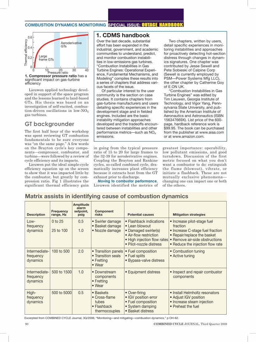
Lieuwen put the ideal simple-cycle efficiency equation up on the screen to show that it was impacted little by the combustor, but greatly by com-pression ratio. Fig 1 illustrates the significant thermal efficiency gain
in going from the typical pressure ratio of 15 to 20 for large frames to the 32-39 for aeroderivative engines. Coupling the Brayton and Rankine cycles, so-called combined cycle, dra-matically increases plant efficiency because it extracts heat from the GT exhaust prior to discharge.
Moving to combustor performance, Lieuwen identified the metrics of
greatest importance: operability, low pollutant emissions, and good turndown. Discussion of the first metric focused on what you don’t want a combustor to do: extinguish the flame (blowout), vibrate, or initiate a flashback. These are not mutually exclusive phenomena—changing one can impact one or both of the others.
1. CDMS handbookOver the last decade, substantial effort has been expended in the industrial, government, and academic communities to understand, predict, and monitor combustion instabili-ties in low-emissions gas turbines. “Combustion Instabilities in Gas Turbine Engines: Operational Experi-ence, Fundamental Mechanisms, and Modeling” compiles these results into a series of chapters that address vari-ous facets of the issue.
Of particular interest to the user community is the section on case studies. It contains chapters from gas-turbine manufacturers and users detailing specific experiences in the development stage and in fielded engines. Included are the basic instability mitigation approaches developed and the tradeoffs encoun-tered between instabilities and other performance metrics—such as NOx emissions.
Two chapters, written by users, detail specific experiences in moni-toring instabilities and approaches for proactively detecting hot-section distress through changes in dynam-ics signatures. One chapter was contributed by Jesse Sewell and Pete Sobieski of Calpine Corp (Sewell is currently employed by PSM—Power Systems Mfg LLC), the other chapter by Catherine Goy of E.ON UK.
“Combustion Instabilities in Gas Turbine Engines” was edited by Tim Lieuwen, Georgia Institute of Technology, and Vigor Yang, Penn-sylvania State University, and pub-lished by the American Institute of Aeronautics and Astronautics (ISBN 156347669X). List price of the 600-page, hardback reference work is $99.95. The book can be purchased from the publisher at www.aiaa.com or at www.amazon.com.
Excerpted from COMBINED CYCLE Journal, 3Q/2006, “Monitoring—and mitigating—combustion dynamics,” p OH-62.
1. Compressor pressure ratio has a significant impact on gas-turbine efficiency
Matrix assists in identifying cause of combustion dynamics
92 COMBINED CYCLE JOURNAL, Third Quarter 2008
DLE systems have particularly sensitive combustors and decisions on tradeoffs are common. One is the optimum mixing time to limit NOx emissions versus the time it takes for autoignition to occur. The more time the better the mixing, but autoigni-tion is the risk and the higher the carbon content, the faster it will hap-pen.
Bullet-point refresher: n Blowout is caused by a low fuel/
air ratio. One way this happens is that load is reduced too quickly: The change in fuel flow is instan-taneous but the inertia of the GT rotor keeps air flowing at a high rate.
Fuel composition influences the blowout limit; addition of hydro-gen, for example, significantly extends the range of operation. Temperature and humidity also impact blowout limit, but general-ly to a lesser degree than a change in fuel composition.
n Flashbacks occur in premix sys-tems when flame speed is higher than the speed at which the fuel and air mixture travels to the combustor. A hydrogen/air mix-ture has the highest flame speed; methane/air is much slower. This is why there are well-defined lim-its on the percentage of hydrogen in GT fuels for premix combustion systems. If you have a great deal of hydrogen to burn, a non-premix combustor is necessary.
n Autoignition refers to an ignition site upstream of the combustor in premix systems. Fuel injected into hot air will autoignite, but the time it takes that to happen is what’s important. You want the fuel and air mixture to move into the com-bustor before ignition occurs. Methane (CH4) has a significantly
higher autoignition temperature than higher hydrocarbons—such as ethane (C2H6), propane (C3H8),
butane (C4H10), etc. This is impor-tant to remember if your fuel source is changing to include LNG—and especially so if your GTs are high-pressure-ratio aeros.
Flame temperature, important because it directly impacts emis-sions, depends primarily on fuel/air ratio and compressor discharge temperature. Fig 2 shows that peak flame temperature occurs at an equivalence ratio of 1.0 (stoichiom-etry) because there is no leftover fuel or air to heat up. To the right of stoichiometry, combustion is fuel rich—that is, there is extra fuel in the mixture that can’t burn because there’s not enough air to support its combustion.
Equivalence ratios of less than unity are fuel lean, meaning there’s oxygen left over after combustion. DLE systems operate in this regime to hold down flame temperature.
Types of flames—diffusion and premixed—was the next topic. The defining characteristic of diffusion or non-premixed flames, is that fuel and air are introduced into the combustor separately and the mixture burns at an equivalence ratio of 1.0. As men-tioned above, this produces the hot-test flame possible along with high levels of NOx and some soot. Diffu-sion flames are robust and offer wide
turndown; also, autoignition and flashback are of little concern.
In the premixed combustion pro-cess used for DLE-equipped turbines, air and fuel are mixed upstream of the combustion chamber, allowing tight control of mixture stoichiometry and, therefore, flame temperature. A few things to keep in mind: n For GTs burning liquid fuels, the
oil or kerosene must be vaporized before the premix step.
n Operability windows of DLE units contract because to avoid extin-guishing the flame.
n Almost all air goes through the front end of the combustor in lean-fuel operation; little is available for cooling.
n Multiple fuel nozzles are required for turndown (one combustor design for large frames relies on five identical fuel nozzles around the combustor can, another on five identical outer burners and one smaller center nozzle). Emissions from natural-gas-fired
land-based engines of greatest importance are NOx (oxides of nitro-gen) and CO (carbon monoxide). Unburned hydrocarbons may be of concern when combustion is not properly tuned and incomplete; SOx emissions occur when fuel contains sulfur; particulates may be notice-able under certain operating condi-tions with specific fuels.
Three mechanisms are associ-ated with NOx formation. So-called “thermal NOx,” that related directly to flame temperature, is the domi-nant mechanism in most GT com-bustors. The other two are “prompt NOx” and the reaction that converts nitrous oxide (N2O) to nitric oxide (NO). Thermal NOx production is controlled by limiting flame tempera-ture by use of premix combustion or by water or steam injection directly into combustion chambers with diffu-sion flames.
High CO levels are a characteris-tic of fuel-rich flames (equivalence ratio greater than 1.0) because there is insufficient oxygen to react fuel to CO2. CO also is found in lean flames because they are relatively cool and the conversion of CO to CO2 depends on temperature—the higher the flame temperature, the faster the conversion. CO ultimately limits engine turndown; the low combus-tion temperatures associated with low-power operation cause a rapid increase in CO level.
In sum, operation at high power is limited by NOx production, at low power by CO production.
SOx emissions, most often associ-ated with liquid fuels—black oil in
Are You Experiencing EHC Varnishing Issues?
Avoid downtime. Learn how to troubleshoot EHC problems from a certified professional who designs systems
for a major power generation OEM.
Contact: Steve Golya, Power Generation General ManagerDees Fluid Power1809 Fashion CourtJoppa, MD [email protected]
Visit booth 116 WTUI 2008
2. Peak flame temperature occurs at an equivalence ratio of 1.0 because there is no leftover fuel or air to heat up
0.5 0.7 0.9 1.1 1.3 1.5 1.7 1.9Equivalence ratio
Ad
iab
atic
flam
e te
mp
erat
ure,
F 2300
2100
1900
1700
1500
StoichiometryFuel lean Fuel rich
COMBINED CYCLE JOURNAL, Third Quarter 2008 93
particular—cannot be reduced dur-ing the combustion process. Fuel-bound sulfur must be removed before combustion. Particulates, or soot, are found most often in fuel-rich diffu-sion flames. Possible health impacts aside, the major problem with par-ticulates is that they radiate heat to the combustor wall.
Combustion instabilitiesCombustion dynamics are pressure waves of defined amplitudes and fre-quencies that are an inherent result of the combustion process. They are caused by large-amplitude acoustic oscillations driven by heat-release oscillations as depicted in Fig 3.
In the typical can-annular combus-tor of a large frame GT, combustion
dynamics can range in frequency from less than 50 Hz to up to about 5000 Hz. In terms of their impact on turbine components, dynamics of these frequencies can range from benign to highly destructive.
Trouble occurs only when the vibrations have large amplitudes or when they occur at frequencies cor-responding to natural resonances in that particular system. Such trouble can culminate with fatigue failure of combustor components, which when released into the flow stream can cause serious damage to other hot-gas-path components.
Reasons why DLE combustion systems are susceptible to severe dynamics problems include the fol-lowing:n They operate near the lean blow-
out limit. Thus such systems are marginally stable to begin with and small perturbations can have very significant impacts.
n A minimal amount of combustor cooling air is used to minimize CO production. This substantially reduces the acoustic damping capability of the combustor. In effect, sound waves resonate in the combustion liner because dilu-tion holes have been eliminated.
n A high-velocity premix section is used to protect against flashback and this maximizes pressure at the flame front.
n Compact reaction zone to limit
CO production concentrates heat release where combustor pressure is at its maximum.
Characteristics of instabilities During instabilities, the combustion process generally excites one or more of the natural acoustic modes of the com-bustor, which is similar to an organ in that it has several natural frequencies. Recall that the natural frequency, or pitch, of each individual organ pipe depends on its length and inner diam-eter. Short pipes with small diameters produce high notes; larger, longer pipes produce the bass tones.
The resonant modes for a combus-tor are known as Helmholtz, longi-tudinal, and transverse. Picture an empty beer bottle. Blowing across the top produces a rumbling sound which is representative of the Helmholtz mode characterized by frequencies often in the range of 10 to 40 Hz. Experience shows that as you make the flame colder (approach blowout), this mode dominates, apparently caused by partial flame extinction.
Longitudinal modes are in the intermediate-frequency range, nomi-nally from 100 to 1500 Hz, and produce a humming sound (Fig 4). Transverse oscillations, either radial or azimuthal, are in the high-frequency range from about 500 to 5000 Hz and particularly destructive.
3. Combustion dynamics are pressure waves of defined amplitudes and frequencies that are an inherent result of the combustion process. They are caused by large-amplitude acoustic oscillations driven by heat-release oscillations as shown above
Heat release Acoustics
94 COMBINED CYCLE JOURNAL, Third Quarter 2008
SPECIAL ISSUE: OUTAGE HANDBOOKCOMBUSTION DYNAMICS MONITORING
They are characterized by screech-ing, which is attributed to the mini-mal film cooling of DLE combustors.
Why instabilities occur. Lieuwen said two important mechanisms in DLE combustors that cause instabilities are these: (1) Equivalence ratio of the reactive mixture oscillates and disturbs the flame, and (2) vortices in the combustor distort the flame. The first is impacted by premixer veloc-ity, fuel injection location, fuel sup-ply line characteristics (length, fuel temperature, etc), and flame location (standoff distance, length, etc).
The key effect of fuel and/or operat-ing conditions on dynamics is through alteration of flame shape and/or loca-tion. In some cases dynamics is made worse, in others better. Changing the fuel does not change the susceptibil-
ity to dynamics (either for better or for worse); rather it moves islands of instability around as shown in Fig 5. Lieuwen noted that some condi-tion exists where every combustor is unstable.
Mitigation strategies The turbine designer has several options to minimize the impact of combustion dynamics. These include varying the combustor geometries, changing fuel-supply system acous-tic response characteristics, install-ing resonators, and beefing up the components known to be vulnerable. However, the design and fabrication
2. CDMS hardware and how it works
A portion of Tim Lieuwen’s course notes concerning the hardware aspects of combus-
tion dynamics monitoring systems, as well as some case histories illus-trating the value of CDM in identify-ing the root causes of com-bustion instabilities, were based in part on materials provided by Marcus Turner and John Brooks of Control Center, the Gas Turbine Efficiency (GTE) company focusing on this business sector.
To dig deeper, the edi-tors met with Turner at the fall 2008 meeting of the CTOTF—Combustion Turbine Operations Task Force. By way of background, Orlan-do-based Control Center provides integrated process control solutions for electric power generation sector, among others. It was established in 1963 and became part of GTE in 2007. To date it has designed and installed more than 100 CDMSs for gas turbines. Reflecting,Turnersaidthatwhen
dry, low-emissions (DLE) combustion systems were first introduced, the gas-turbine OEMs recognized that there was an issue with combustion dynamics and offered a “seasonal tuning” service. Typically, special-
ists would visit a plant in the spring and fall and tune the engine for best balance between NOx and dynamics based on site conditions.
Tuning complete, the technicians packed up their diagnostic equipment and data and left. Users were not equipped to monitor dynam-ics or to make additional
tuning changes and they were blind to any component distress that might be occurring in their engines.
CDMSs were developed to respond to this market need, Turner continued. Briefly, they provide both the ability to tune for emissions com-pliance as necessary and to warn of damage to combustion hardware, or of impending damage.
There are two types of systems that allow operators to run their tur-
bines at optimum settings: portable and permanent. The latter includes systems designed for monitoring only and others that tie into the con-trol system for active control of the engine.
Portable tuning systems, Turner said while pointing to the photo on his computer screen (Fig A here), allow owners to take advantage of CDMS benefits without investing in hardware for each engine. These might make most economic sense in low-hours peaking facilities. He explained how this equipment is arranged and works:
Sensors are connected to some, or all, combustors to monitor pres-sure fluctuations. Data are fed to a PC analyzer that breaks down the information into amplitude versus frequency. The frequency range typically is subdivided into narrow bands, each with their own amplitude limit. Goal of the technician doing the tuning is to minimize dynamics amplitudes while maintaining emis-sions below permit limits.
Permanent monitoring systems
A B
Turner
4. Longitudinal modes produce a humming sound; transverse oscilla-tions, either radial or azimuthal, are characterized by screeching
axial length of the combustor and area within the chamber.
n Cooling and coating requirements that must be balanced with the overall air flow.
n Thermal expansion consider-ations. Consider that the metal temperatures experienced by an F-class transition piece range from ambient temperature while the unit is on turning gear to approximately 1500F when the unit is at full-fire.For resistance to intermediate-
frequency dynamics, the likely design
solution is to make affected com-ponents more robust, in order to withstand low-cycle fatigue mecha-nisms. To combat higher frequency dynamics, the likely design solution requires keeping the amplitudes of the dynamics low enough to avoid high-cycle fatigue.
Remember, it’s not just large amplitudes that the designer must evaluate, but also resonant frequen-cies. Each pilot-nozzle assembly, for example, may have a different natu-ral frequency because of slight dif-ferences in diameter, wall thickness, and length.
Complicating the designer’s chal-lenge is the fact that any one com-bustion component may have several natural frequencies. For example, the panels of a transition piece may exhibit relatively low natural frequen-cies (100 to 200 Hz), while the end-rail assemblies of that transition piece may have higher natural frequencies (typically greater than 500 Hz).
Passive control approaches used when dynamics problems are identi-fied, Lieuwen said, include the fol-lowing:n Increase pilot fuel. Usually, more
pilot fuel helps mitigate dynam-ics. Essentially pilot fuel is used as a “knob” to make a flame more stable by making it hotter. Howev-er, NOx emissions increase along with flame stability.
n Resonators. Effective control of combustor dynamics also has been achieved with the installation of Helmholtz resonators; they atten-uate specific frequencies in the combustion system (Fig 6). The resonators are tuned for specific frequencies where dynamics are known to occur.
n Decouple fuel-line acoustics by choking/detuning.
n Symmetry breaking. Use of mul-tiple fuel systems to vary the fuel/air profile among the burners. For example, in a large frame engine with five burners per combustor, one fuel system might supply two burners; another, the remaining three burners. The goal is to make the acoustic response of each set of injectors different. There may be a small NOx penalty using this approach.
n Vary the convective time lag for the equivalence-ratio oscillation mechanism.
Eliminating instabilitiesCase history #1. Dynamics in the inter-mediate-frequency range (defined here as 100 to 1500 Hz) are what damaged the lower panel of a transi-
2. CDMS hardware and how it works operate continuously, Marcus added, alerting operators when limits are exceeded and logging all alarms. They permit tuning as-needed, such as when significant changes to fuel quality, ambient air, or combus-tion hardware (nozzle obstruction, cracked transition piece, etc) occur. He said permanent systems have pressure sensors and a PC/analyzer justliketheportablesystems.Reflectingagain,Turnernoted
that most of the permanent systems Control Center has installed over the years have low-temperature sensors mounted outside the turbine enclo-sure for GE Energy engines and on the inside for Siemens machines. They are connected through sens-ing lines to each combustor. A drawback with this arrangement is condensation; any buildup of mois-ture has to be purged, requiring additional equipment and mainte-nance. However, up until recently, low-temperature sensors were much less expensive and far more reli-able than those available for the high-temperature service within the enclosure; and, they were much easier to service—especially outside the enclosure on GT turbines.
Today, a few manufacturers offer sensors capable of service at tem-peratures above 1000F and they can be mounted directly on combustors. These sensors have been deployed on many turbines and results thus farhavebeenfavorable.Themajorbenefit of high-temperature sensors, which cost more than the low-tem-perature ones, is that their use elimi-nates the need for sensing lines and the related purging equipment.
There is an expectation that the new sensors may provide more infor-mation than those specified previ-ously because they directly measure dynamics. But this has not yet been
confirmed.Thejuryalsoisstilloutonthe life expectancy of the new sen-sors.
Intermediate-temperature (IT) sensors (rated up to 700F) also are another option. They offer the advantages of high-temperature sen-sors but require a special mounting system that moves the sensor to a cooler location (Fig B). Turner thinks the IT system is a good compromise between cost and maintenance while still maintaining desired performance.
Active control. Turner changed subjectsandlookedahead.Thepromise of controlling the GT based on input from the CDMS—so-called active control—is the direction indus-try leaders are headed, confirming what Lieuwen said in the workshop. But as the professor stressed, this requires a database of engine behav-iors to guide “decision-making” by the CDMS. The gathering of informa-tion for that database is on-going and GTE/Control Center is participating in the process.
Active control, for those unfamiliar with the term, means that the CDMS is linked to the turbine DCS and com-bustion dynamics are displaced on the DCS screen along with other sys-tem variables. Turner says this allows for continuous tuning as the fuel/air ratiovaries,therebyadjustingauto-matically for changes in fuel quality and ambient conditions. The benefits: Optimal balance between emissions and dynamics, and longer parts life.WiththeCDMSspeakingdirectly
to the DCS, a stepped run-back—among other changes—would be initiated if dynamics exceed a preset threshold, thereby giving you a better chance of avoiding engine damage. This action is virtually instantaneous, saving the valuable seconds it would take a top operator to respond to a high-dynamics alarm condition.
5. Changing the fuel does not change the susceptibility to dynamics (either for better or for worse); rather it moves islands of instability
Operating line
Firin
g te
mp
erat
ure
Shifted dynamics islands
“Baseline” dynamics islands
96 COMBINED CYCLE JOURNAL, Third Quarter 2008
SPECIAL ISSUE: OUTAGE HANDBOOKCOMBUSTION DYNAMICS MONITORING
tion piece in one gas turbine (Fig 7). Investigation revealed that the root cause was an incorrect valve posi-tion on the combustor bypass system. The incorrect valve position substan-tially increased the amplitudes of intermediate-frequency combustor dynamics, leading to fatigue failure and crack propagation. Potential design solutions included elimination of the combustor-bypass system, and a more robust design of the transi-tion piece.
Case history #2. Dynamics in the high-frequency range (above 1500 Hz) caused damage to combustor bas-kets at three different powerplants (Fig 8). In these cases, equipment changes apparently had reduced the damping in the system as originally designed. Potential solutions here included equipping the baskets with resonators, adjusting the inlet-guide-vane position schedule, and increas-ing the amount of steam injection (on the turbines that use steam for power augmentation). Full-scale tests using various combinations of combustor baskets and transition pieces iden-tified configurations with improved damping capabilities.
The accompanying table is helpful for identifying the potential causes of combustion instabilities in the can-annular systems common to frame engines.
Monitoring dynamicsWhile GT manufacturers are work-ing continually to improve combus-tor designs, users can take steps at
the plant level to monitor and detect dynamics before they cause exten-sive damage. As detailed in the pre-vious sections of this article, a GT’s flame-stability margin is, to a large extent, a function of site-specific, dynamic parameters—including fuel composition, the amount of wear on combustion-liner seals, and ambient conditions.
These parameters vary over time and a “best practice” to consider is tuning each DLN combustor during plant commissioning to get baseline data and periodically thereafter. Many plants follow a regimen of semi-annual tuning as the seasons change, typically bringing in special-ly trained engineers to perform the sensitive adjustments using portable pressure-monitoring equipment (Sidebar 2).
An increasingly popular alterna-tive is to install a permanent online monitoring system to continuously measure dynamic pressure pulsa-tions and provide early warning when the combustor is out-of-tune.
Robust software and skilled ana-lysts can interpret the data collected by the CDMS. The latest versions of these systems even provide protec-tion logic to automatically unload and protect the GTs during excur-sions of combustion dynamics. So-called “active systems” are said to provide the best level of protection against damaging amplitudes and frequencies.
Value propositionThe CDMS offers considerable value beyond preventing a unit trip because of combustion instability. Think of it as a GT health monitoring tool that alerts plant staff to a possible hardware problem that should be addressed at the next scheduled out-age to correct a condition that could cause a forced outage and the need for expensive repairs.
Lieuwen suggested that if you observe combustion instabilities in most cans, you probably have a tun-ing issue, but if the instability is confined to one can, or a few adjacent cans, you may have a part failure to deal with. The CDMS is a “first alert” to problems such as pilot-nozzle weld cracking, transition-piece cracking, flow obstructions, etc.
Two case studies were presented, one on a flow obstruction in the premixer and the other on combus-tion liner cracking; both were taken from the book referenced in Sidebar 1. The first was identified by occa-sional spikes of low-frequency mode above the alarm threshold in one can. Coincident alarms came from spikes in the flashback thermocouple below the threshold that would initiate a unit trip. Investigators found a piece of wire across the swirler.
The second case presented was particularly instructive. The user reported, “During the week prior to the failure, combustion dynamics levels doubled. It is believed that the [combustion liner] crack had been propagating during the week, and then opened up around midnight, marked by a sudden step change in dynamics levels.”
Lieuwen urged all users to notify
8. High-frequency dynamics were the culprit at three powerplants where combustor baskets were damaged
7. Intermediate-frequency dynamics damaged lower panel of this transition piece
Thick TBC on baskets reduces cooling flow
Resonators to reduce dynamics
6. Installation of tuned resonators is one way to dampen high-frequency dynamics. Use of thick thermal-barrier coatings on combustor baskets also reduces the potential for HFD
COMBINED CYCLE JOURNAL, Third Quarter 2008 97
him of combustion instabilities that point to hardware issues. He is working with EPRI to build a database containing “normal” and “anomalous” behavior from which failure precursors can be extracted and back-tested against (for more detail, access www.combinedcy-clejournal.com/archives.html, click 2Q/2008, click “501F Users Group” on issue cover, scroll to “Using advanced CDM analysis to improve reliability” on p 22).
Consistency in data sets across different machines is important for guiding “decision-making” by an active CDMS. No owner/opera-tor wants to give the active CDMS control of its units until the user is sure there is a very low probability of spurious trips.
Another area under investigation is detection and control of lean blow-out (LBO). Impending blowout can be identified by monitoring of flame acoustics.
Work by Lieuwen and others shows that blowout often is preceded by a low-frequency rumble and by sporadic “bursts” in signal that are not at a specific frequency. This information can be used to develop an algorithm that can be incorporat-ed into existing software to prevent lean blowout from occurring.
Much work is ongoing in the field
of active control. Example: An idea implemented by one gas-turbine OEM that Lieuwen discussed had to do with using a pressure signal from the CDMS as input to the control system. That signal is used to pulse fuel to the combustor with a second-ary injector that is out of phase to the oscillations.
Looking toward the future, Lieuwen next talked about the promise of real-time determination of combustor sta-bility margin. Today, he said, CDMSs are only used to tell you how big the dynamics is. It doesn’t provide infor-mation on stability margin when the turbine is “quiet.”
Knowing the stability margin would allow you to forecast when dynamics will appear as average seasonal temperatures change and understand how changing fuel com-position (for example, when LNG is added to the pipeline) impacts dynamics.
Lieuwen suggested a method of doing this in an ASME paper, “Online Combustor Stability Margin Assessment Using Dynamic Pressure Data” (GT2004-53149). He briefly explained the mathematics involved and said that Alta Solutions Inc, San Diego, experts in machinery diag-nostics, had already programmed a software module to calculate stability margin and was looking for demon-
stration sites. Compressor surge/stall detection
is another “farther out” potential use of CDMS. Lieuwen said that all noise sources upstream of the combustor can be “heard” in the combustion chamber. He reasoned that CDM could be used to achieve the following:n Optimize compressor pressure
ratio by monitoring surge/stall precursors.
n Detect anomalous blade vibra-tions to identify failure precursors and prevent engine damage. ccj