260
REFERENCE MANUAL Access Control Software Version 4.2 CENTAUR
REFERENCE MANUAL
Access Control SoftwareVersion 4.2
CENTAUR
ii Manufacturing Access Control Since 1985
CENTAUR 4.2
REFERENCE MANUAL
Copyright (C) 2006-2008 CDVI Americas LTD. All rights reserved. Centaur access control system software is protected by copyright law and international treaties. Unauthorized reproduction or distribution of this program, or any portion of it, may result in severe civil and criminal penalties, and will be prosecuted to the maximum extent possible under law.
All other brand and product names are trademarks or registered trademarks of their respective companies.
The information contained in this publication is subject to change without notice.
xxx____Access Control Software____xxx

Table Of Contents
CENTAUR 4.2Access Control Software
REFERENCE MANUAL
iiiManufacturing Access Control Since 1985
INSTALLING AND USING CENTAUR ................................................................................................................................................ 1Centaur Editions ........................................................................................................................................................................... 2Installation Overview .................................................................................................................................................................... 3Centaur Server ............................................................................................................................................................................. 3Centaur Administration Console (Workstation) ............................................................................................................................. 7Setting Centaur as a Service Under Windows .............................................................................................................................. 9Plugging the Hardlock Key ......................................................................................................................................................... 10Starting the Centaur Server and Software .................................................................................................................................. 11Software Modules ....................................................................................................................................................................... 13
UNDERSTANDING THE CENTAUR USER INTERFACE ................................................................................................................ 15User Interface Overview ............................................................................................................................................................. 16Typing Names and Notes ........................................................................................................................................................... 22
SITES ................................................................................................................................................................................................ 23Adding a Site .............................................................................................................................................................................. 24Modifying a Site .......................................................................................................................................................................... 27Deleting a Site ............................................................................................................................................................................ 38Communicating with a Site ......................................................................................................................................................... 38
HOLIDAYS ........................................................................................................................................................................................ 39Adding a Holiday ........................................................................................................................................................................ 40Modifying a Holiday .................................................................................................................................................................... 40Deleting a Holiday ...................................................................................................................................................................... 41
SCHEDULES ..................................................................................................................................................................................... 43Adding a Schedule ..................................................................................................................................................................... 44Modifying a Schedule ................................................................................................................................................................. 44Deleting a Schedule ................................................................................................................................................................... 47
CONTROLLERS ................................................................................................................................................................................ 49Adding Controllers ...................................................................................................................................................................... 50Modifying a Controller ................................................................................................................................................................. 52Deleting a Controller ................................................................................................................................................................... 62Online Controller Firmware Upgrades ........................................................................................................................................ 63Download .................................................................................................................................................................................... 64Other Controller Management Options ....................................................................................................................................... 65
DOORS .............................................................................................................................................................................................. 67Adding Doors .............................................................................................................................................................................. 68Modifying a Door ........................................................................................................................................................................ 69Deleting a Door ........................................................................................................................................................................... 80Display Door Status .................................................................................................................................................................... 81
ACCESS LEVELS ............................................................................................................................................................................. 83Adding an Access Level ............................................................................................................................................................. 84Modifying an Access Level ......................................................................................................................................................... 84Deleting an Access Level ........................................................................................................................................................... 86
iv Manufacturing Access Control Since 1985
CENTAUR 4.2Table of Contents
REFERENCE MANUAL
CARDS ..............................................................................................................................................................................................87Adding Cards ..............................................................................................................................................................................89Modifying a Card .........................................................................................................................................................................91Deleting a Card ...........................................................................................................................................................................95Centaur Card Management Feature ...........................................................................................................................................96Centaur Card Import/Export Feature ........................................................................................................................................102
ELEVATOR CONTROL ...................................................................................................................................................................105Overview of Elevator Control ....................................................................................................................................................106
RELAYS ...........................................................................................................................................................................................109Adding Relays ...........................................................................................................................................................................110Modifying a Relay .....................................................................................................................................................................110Deleting a Relay .......................................................................................................................................................................113Display Relay Status and Manual Controls ...............................................................................................................................113
INPUTS ............................................................................................................................................................................................115Connecting Inputs .....................................................................................................................................................................116Adding Inputs ............................................................................................................................................................................119Modifying an Input ....................................................................................................................................................................119Deleting an Input .......................................................................................................................................................................124
OUTPUTS ........................................................................................................................................................................................125Overview of Output Programming .............................................................................................................................................126Adding Outputs .........................................................................................................................................................................127Modifying an Output ..................................................................................................................................................................127Deleting an Output ....................................................................................................................................................................131Display Output Status and Manual Controls .............................................................................................................................131
EVENTS ...........................................................................................................................................................................................133Event Definition Overview .........................................................................................................................................................134Event Schedules and Device Activation ...................................................................................................................................135Alarm Acknowledgement ..........................................................................................................................................................137Event-Activated CCTV Control .................................................................................................................................................140
GROUPS ..........................................................................................................................................................................................141What Are Groups? ....................................................................................................................................................................142Adding a Group .........................................................................................................................................................................142Modifying a Group ....................................................................................................................................................................143Deleting a Group .......................................................................................................................................................................144Manual Control of Door and Relay Groups ...............................................................................................................................145
OPERATORS ..................................................................................................................................................................................147Overview of Operators ..............................................................................................................................................................148Adding a Security Level, Permission, or Operator ....................................................................................................................148Modifying a Security Level, Permission, or Operator ................................................................................................................149Deleting a Security Level, Permission, or Operator ..................................................................................................................154
CCTV COMMANDS .........................................................................................................................................................................155Adding a CCTV Command .......................................................................................................................................................156Modifying a CCTV Command ...................................................................................................................................................156Deleting a CCTV Command .....................................................................................................................................................157

vManufacturing Access Control Since 1985
CENTAUR 4.2Access Control Software
REFERENCE MANUAL
OPTIONS ......................................................................................................................................................................................... 159General Centaur Options .......................................................................................................................................................... 160Event Colour Definitions ........................................................................................................................................................... 161Operator Timeout ..................................................................................................................................................................... 162Log File ..................................................................................................................................................................................... 162
MANUAL CONTROLS .................................................................................................................................................................... 163Event Display ............................................................................................................................................................................ 164Manual Controls ....................................................................................................................................................................... 165
DATABASE MANAGEMENT .......................................................................................................................................................... 171What are the Centaur Databases? ........................................................................................................................................... 172Database Management Module ............................................................................................................................................... 172Database Backup Scheduler .................................................................................................................................................... 178
CENTAUR WAVE PLAYER ............................................................................................................................................................ 181Centaur Wave Player ............................................................................................................................................................... 182
DCOM CONFIGURATION ............................................................................................................................................................... 183DCOM Configuration for Windows XP ...................................................................................................................................... 184DCOM Configuration for Windows 2003 Server ....................................................................................................................... 206DCOM Configuration for Windows 2000 Pro and Server ......................................................................................................... 235
WARRANTY .................................................................................................................................................................................... 243

vi Manufacturing Access Control Since 1985
CENTAUR 4.2Table of Contents
REFERENCE MANUAL
1
CENTAUR 4.2Access Control Software
Manufacturing Access Control Since 1985
REFERENCE MANUAL
Chapter 1: Installing and Using Centaur
What Will I Find?Centaur Editions . . . . . . . . . . . . . . . . . . . . . . . . . . . . . . . . . . . . . . . . . . . . . . . . . . . . . . . . . . . . . . . . . . . . . . . . . . . . . . . . . . . . . . . . . 2Installation Overview . . . . . . . . . . . . . . . . . . . . . . . . . . . . . . . . . . . . . . . . . . . . . . . . . . . . . . . . . . . . . . . . . . . . . . . . . . . . . . . . . . . . . . 3Centaur Server. . . . . . . . . . . . . . . . . . . . . . . . . . . . . . . . . . . . . . . . . . . . . . . . . . . . . . . . . . . . . . . . . . . . . . . . . . . . . . . . . . . . . . . . . . . 3Centaur Administration Console (Workstation) . . . . . . . . . . . . . . . . . . . . . . . . . . . . . . . . . . . . . . . . . . . . . . . . . . . . . . . . . . . . . . . . . . 7Setting Centaur as a Service Under Windows. . . . . . . . . . . . . . . . . . . . . . . . . . . . . . . . . . . . . . . . . . . . . . . . . . . . . . . . . . . . . . . . . . . 9Plugging the Hardlock Key. . . . . . . . . . . . . . . . . . . . . . . . . . . . . . . . . . . . . . . . . . . . . . . . . . . . . . . . . . . . . . . . . . . . . . . . . . . . . . . . . 10Starting the Centaur Server and Software . . . . . . . . . . . . . . . . . . . . . . . . . . . . . . . . . . . . . . . . . . . . . . . . . . . . . . . . . . . . . . . . . . . . . 11Software Modules . . . . . . . . . . . . . . . . . . . . . . . . . . . . . . . . . . . . . . . . . . . . . . . . . . . . . . . . . . . . . . . . . . . . . . . . . . . . . . . . . . . . . . . 13
Centaur is an advanced and powerful access control management software. The following chapter contains important information concerning the installation and use of this software.
2 Manufacturing Access Control Since 1985
CENTAUR 4.2Installing and Using Centaur
REFERENCE MANUAL
Centaur Edit ionsCentaur software is available in four editions.
Lite EditionWith the lite edition you can:
• Create 1 site• Connect through serial port RS-232• Create up to 512 cards• Create 2 controllers • Create up to 16 doors
Standard EditionWith the standard edition you can:
• Create 64 sites• Connect to your site via TCP/IP, direct, or dial-up• Create up to 2048 cards per site• Create 16 controllers per site• Create up to 128 doors per site• Control up to 32 elevator carts• Provide access to 64 floors per elevator cart• Create 128 floor groups
Professional EditionThis edition includes all features of the Standard Edition, in addition you can:
• Connect to your site via TCP/IP, direct, or dial-up• Create up to 8196 cards per site• Create up to 64 controllers per site• Create up to 512 doors per site• Create up to128 elevator carts per site
Enterprise EditionThis edition includes all features of the Professional Edition, in addition you can:
• Create up to 16 384 cards per site• Create up to 256 controllers per site• Create up to 2048 doors per site• Create up to 512 Elevator carts per site
Demo ModeAll editions will run in Demo Mode when a hardlock key is not detected. Communication is disabled when in Demo Mode.

3Manufacturing Access Control Since 1985
CENTAUR 4.2Installing and Using Centaur
REFERENCE MANUAL
Instal lat ion OverviewThis section details how to install the Centaur software including the Centaur Server and Administration Console (Workstation) available on the Centaur 4.1 CD.
Each edition of the Centaur software (Lite, Standard, Professional, and Enterprise) has two different applications - the Server and the Administration Console (Workstation). Please note that the terms Administration Console and Workstation both refer to the same software User Interface, and are used interchangeably.
Centaur ServerThe Centaur Server manages the controllers and maintains the access control system’s databases. The Centaur 4.1 CD includes the Centaur Server, the Administration Console, several software features, and the reference manuals for these software features, which are all automatically installed together. The reference manuals for Centaur hardware components are also available on the Centaur 4.1 CD.
Computer Requirements (Centaur Server)The Centaur software is designed to operate with IBM or IBM compatible computers running a suitable Windows operating system as detailed in the “Operating System Requirements (Centaur Server)”.
• Pentium 4• 512MB RAM (1GB for superior performance)• 1GB recommended; 4GB for larger installations• RS-232 serial port (depending on the installation, more than one may be required)• For dial-up sites, the Centaur Server and each dial-up site requires a US Robotics Sportster 56k baud modem (external/
internal). Other modems can be used, but we recommend the above-mentioned modem. WinModems are not supported. • Super VGA Monitor
Operating System Requirements (Centaur Server)The Centaur Server has been tested on the following operating systems:
• Windows XP Home or Professional Edition (English and French) Service Pack 2• Windows 2003 Server Edition (English and French)• Windows 2000 Professional Edition (English, French, and Spanish) • Windows 2000 Server Edition (English, French, and Dutch)
Other software requirements (available on the CD):• DCOM• MDAC 2.8• Microsoft Database Engine (MSDE 2000)• Microsoft Internet Explorer (version 6.0 or higher)• Acrobat Reader 6.0 or higher• XML 3.0 Parser

4 Manufacturing Access Control Since 1985
CENTAUR 4.2Installing and Using Centaur
REFERENCE MANUAL
Controller Requirements• CT-V900-A Rev. 200/210/220/230/260 require firmware R2-C3-65 or higher. • CT-V900-A Rev. 100/110 require firmware R1-01-79 or higher.
For more information on how to update the controllers, refer to “Online Controller Firmware Upgrades” on page 63 or Online Help.
Technical SupportFor technical support in Canada or the U.S., call 1-866-610-0102, Monday to Friday from 8:00 a.m. to 8:00 p.m. EST. For technical support outside Canada and the U.S., call 00-1-450-682-7945, Monday to Friday from 8:00 a.m. to 8:00 p.m. EST. Please feel free to visit our website at www.cdvi.ca.

5Manufacturing Access Control Since 1985
CENTAUR 4.2Installing and Using Centaur
REFERENCE MANUAL
Installing/Updating the Centaur ServerThis section describes how to install or update the Centaur Server.
The Centaur Server software must be installed on the computer where all controllers are or will be connected.
1. Insert the Centaur 4.1 CD into the computer’s CD-ROM drive.
2. If the auto run feature is enabled, go to the step 3. Otherwise, click Run from the Start menu, type the appropriate drive indicator (x:\) followed by setup.exe or click Browse to search for the setup.exe file. Click OK.
3. The Centaur 4.1 Setup window will appear. If this is a new installation of the Centaur software, click Next and go to the next step. To update previously installed Centaur software, select Update, click Next, follow the on-screen instructions, and click Finish.
4. The License Agreement window will appear. To install the Centaur software, select I accept the terms of the license agreement, and click Next.
5. The Type of installation window will appear. To install the Centaur Server, select System management and communication with control panels (Server and Workstation). If you wish to select a different folder destination for the Centaur or MSDE software, click the appropriate Browse button, choose the folder destination, and click OK. Click Next.
6. The Selecting Languages window will appear. The Centaur Server supports three languages. English is automatically supported by default. Select two other languages and click Next.
7. The Centaur Pre-Requisites window will appear. Setup automatically detects and lists which prerequisites have and have not been installed on your computer. To install the required software components, click Next and follow the on-screen instructions. If all prerequisites are already installed, the setup will skip this step (go to the next step).
8. When Setup has completed the installation of the Centaur software, the InstallShield Wizard Complete window will appear. Select if you wish to restart your computer now or later. Click Finish.
For new installations of the Centaur software or when upgrading to the Centaur 4.1 software from a previous version, you need to upgrade the controller firmware version to R2-C3-65 or higher.
To install the Centaur 4.1 software on Windows 2000/2003/XP operating systems, you must be logged on as Administrator.
The Administration Console is installed with the Centaur Server by default. The Centaur software is installed by default to C:\Program Files\CDV Americas\Centaur. The MSDE software is installed by default to C:\Program Files\Microsoft SQL Server.

6 Manufacturing Access Control Since 1985
CENTAUR 4.2Installing and Using Centaur
REFERENCE MANUAL
In installations where remote workstations will access the Server through a network, DCOM must be configured on the Centaur Server computer (refer to “DCOM Configuration” on page 183).
Before you can use the Centaur software, you must restart your computer.
An icon for the Administration Console is automatically added to your computer desktop.
The Centaur software manuals are automatically installed on your computer. To locate a software manual, click Start Programs CDV Americas Centaur Administration Console Manuals.
The Centaur hardware manuals must be manually installed on your computer. To locate the hardware manuals on the CD, open Windows Explorer. Click on the appropriate drive indicator (x:\) from which the Centaur CD is inserted. Double-click the Manuals folder. Double-click the Hardware Manuals folder. Copy and paste the manual(s) to the computer drive and folder of your choice.
7Manufacturing Access Control Since 1985
CENTAUR 4.2Installing and Using Centaur
REFERENCE MANUAL
Centaur Administration Console (Workstation)This section describes how to install a Centaur Administration Console on a networked workstation.
The Centaur Administration Console is installed on a networked workstation computer using the Centaur 4.1 CD. The Centaur Administration Console allows operators to monitor and manage the access control system remotely by accessing the Centaur Server’s databases and its controllers through a network.
Computer Requirements (Workstation)The Centaur software is designed to operate with IBM or IBM compatible computers running a suitable Microsoft Windows operating system as detailed in the Operating System Requirements below.
• Pentium 4• 512MB RAM (1GB for superior performance)• 300MB free disk space • Super VGA Monitor
Operating System Requirements (Workstation)The Centaur Administration Console has been tested on the following operating systems:
• Windows XP Home or Professional Edition (English and French) Service Pack 2• Windows 2003 Server Edition (English and French) • Windows 2000 Professional Edition (English, French, and Spanish)• Windows 2000 Server Edition (English, French, and Dutch)
Other software requirements (available on the CD):• DCOM• MDAC 2.8• Microsoft Internet Explorer (version 6.0 or higher)• Acrobat Reader 6.0 or higher• XML 3.0 Parser
In order for a remote workstation to access the Server, DCOM must be configured on the Centaur Server computer (refer to “DCOM Configuration” on page 183).
8 Manufacturing Access Control Since 1985
CENTAUR 4.2Installing and Using Centaur
REFERENCE MANUAL
Installing/Updating the Administration Console (Workstation)This section describes how to install or update the Centaur Administration Console (Workstation).
1. Insert the Centaur 4.1 CD into the computer’s CD-ROM drive.
2. If the auto run feature is enabled, go to the next step. Otherwise, click Run from the Start menu, type the appropriate drive indicator (x:\) followed by setup.exe or click Browse to search for the setup.exe file. Click OK.
3. The Centaur Setup window will appear. If this is a new installation of the Centaur software, click Next and go to the step 4. To update previously installed Centaur software, select Update, click Next, follow the on-screen instructions, and click Finish.
4. The License Agreement window will appear. To install the Centaur software, select I accept the terms of the license agreement and click Next.
5. The Type of installation window will appear. To install the Administration Console (Workstation), select System management only, will not communicate with control panels (Workstation only). If you wish to select a different folder destination for the Centaur software, click the appropriate Browse button, choose the folder destination, and click OK. Click Next.
6. The Centaur Pre-Requisites window will appear. Setup automatically detects and lists which prerequisites have and have not been installed on your computer. To install the required software components, click Next and follow the on-screen instructions. If you already have all prerequisites, Setup will skip this step (continu with next step).
7. When Setup has completed the installation of the Centaur software, the InstallShield Wizard Complete window will appear. Select if you wish to restart your computer now or later. Click Finish.
The Centaur software is installed by default to C:\Program Files\CDV Americas\Centaur.
Before you can use the Centaur software, you must restart your computer.
An icon for the Administration Console (Workstation) is automatically added to your computer desktop.
The Centaur software manuals are automatically installed on your computer. To locate a software manual, click Start, Programs, CDV Americas, Centaur Administration Console, and Manuals.
The Centaur hardware manuals must be manually installed on your computer. To locate the hardware manuals on the CD, open Windows Explorer. Click on the appropriate drive indicator (x:\) from which the Centaur CD is running. Double-click the Manuals folder. Double-click the Hardware Manuals folder. Copy and paste the manual(s) to the computer drive and folder of your choice.

9Manufacturing Access Control Since 1985
CENTAUR 4.2Installing and Using Centaur
REFERENCE MANUAL
Setting Centaur as a Service Under WindowsThese instructions pertain to Windows 2000/2003/XP operating systems, and will enable the Auto-start service when OS starts feature in the Centaur Service Manager. This feature will automatically start the Centaur Server when you start the computer. You will only need to start the Centaur Administration Console.
1. If the Centaur Service Manager is already stopped and has been exited, proceed to step 5. Otherwise, click Start Programs CDV Americas Centaur Centaur Service Manager. The Centaur Service Manager window will
appear.
2. Click Stop. The Operator Logon window will appear.
3. Enter your Centaur Logon ID and Password and click OK. The default Logon ID is Admin and the default Password is Admin.
4. From the icon tray, right-click the Centaur Service Manager icon and click Exit.
5. To manually set Centaur as a service under Command Prompt, go directly to step 6. Otherwise, open Windows Explorer and locate drive (C:). Double-click Program Files, double-click CDV Americas, double-click Centaur, double-click Centaur Server, and double-click Service.bat. Proceed to step 7.
6. To manually set Centaur as a service under Command Prompt, click Start Programs Accessories Command Prompt.
a) The Command Prompt window will appear. Type cd\program files\cdv americas\centaur\centaur server and press Enter.
b) Type spxsvr.exe /service and press Enter. Close the Command Prompt window.
The Operator Rights Validation window will not appear if Centaur is set as a service under Windows.
Ensure that there is a space between spxsvr.exe and the front slash (/).
Centaur Service Manager icon
10 Manufacturing Access Control Since 1985
CENTAUR 4.2Installing and Using Centaur
REFERENCE MANUAL
7. Click Start Programs CDV Americas Centaur Centaur Service Manager.
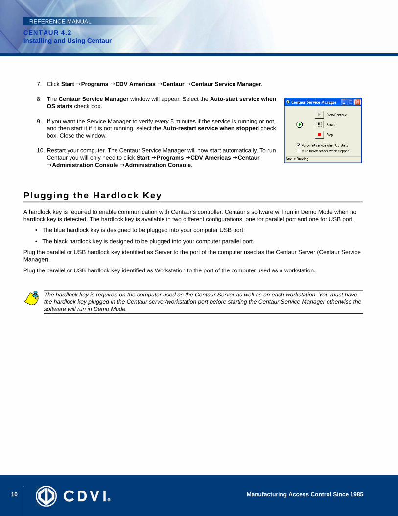
8. The Centaur Service Manager window will appear. Select the Auto-start service when OS starts check box.
9. If you want the Service Manager to verify every 5 minutes if the service is running or not, and then start it if it is not running, select the Auto-restart service when stopped check box. Close the window.
10. Restart your computer. The Centaur Service Manager will now start automatically. To run Centaur you will only need to click Start Programs CDV Americas Centaur
Administration Console Administration Console.
Plugging the Hardlock KeyA hardlock key is required to enable communication with Centaur‘s controller. Centaur‘s software will run in Demo Mode when no hardlock key is detected. The hardlock key is available in two different configurations, one for parallel port and one for USB port.
• The blue hardlock key is designed to be plugged into your computer USB port.
• The black hardlock key is designed to be plugged into your computer parallel port.
Plug the parallel or USB hardlock key identified as Server to the port of the computer used as the Centaur Server (Centaur Service Manager).
Plug the parallel or USB hardlock key identified as Workstation to the port of the computer used as a workstation.
The hardlock key is required on the computer used as the Centaur Server as well as on each workstation. You must have the hardlock key plugged in the Centaur server/workstation port before starting the Centaur Service Manager otherwise the software will run in Demo Mode.
11Manufacturing Access Control Since 1985
CENTAUR 4.2Installing and Using Centaur
REFERENCE MANUAL
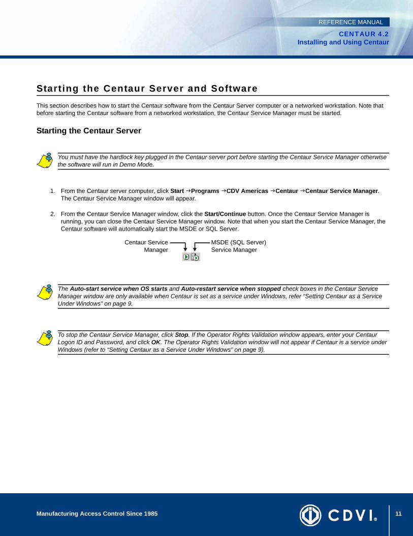
Starting the Centaur Server and SoftwareThis section describes how to start the Centaur software from the Centaur Server computer or a networked workstation. Note that before starting the Centaur software from a networked workstation, the Centaur Service Manager must be started.
Starting the Centaur Server
1. From the Centaur server computer, click Start Programs CDV Americas Centaur Centaur Service Manager. The Centaur Service Manager window will appear.
2. From the Centaur Service Manager window, click the Start/Continue button. Once the Centaur Service Manager is running, you can close the Centaur Service Manager window. Note that when you start the Centaur Service Manager, the Centaur software will automatically start the MSDE or SQL Server.
You must have the hardlock key plugged in the Centaur server port before starting the Centaur Service Manager otherwise the software will run in Demo Mode.
The Auto-start service when OS starts and Auto-restart service when stopped check boxes in the Centaur Service Manager window are only available when Centaur is set as a service under Windows, refer “Setting Centaur as a Service Under Windows” on page 9.
To stop the Centaur Service Manager, click Stop. If the Operator Rights Validation window appears, enter your Centaur Logon ID and Password, and click OK. The Operator Rights Validation window will not appear if Centaur is a service under Windows (refer to “Setting Centaur as a Service Under Windows” on page 9).
Centaur ServiceManager
MSDE (SQL Server)Service Manager

12 Manufacturing Access Control Since 1985
CENTAUR 4.2Installing and Using Centaur
REFERENCE MANUAL
Starting the Centaur Software
1. From the Centaur server computer or from a networked workstation, click Start Programs CDV Americas Centaur Administration Console Administration Console. The Centaur Logon window will appear.
2. From the Centaur Logon window, type the appropriate Logon ID and Password. The default Logon ID is Admin and the default Password is Admin. If you are trying to log on to a Centaur Server that is on a network, type the Server computer’s network name or IP address in the Computer text box. From the Language drop-down list, select the desired language. Click OK.
If you are starting a software module, click Start Programs CDV Americas Centaur Administration Console the appropriate software.
To allow access from remote workstations, DCOM must be configured on the Centaur Server computer (refer to “DCOM Configuration” on page 183).
When starting Centaur for the first time, a dialogue box appears asking if you would like to use the site configuration wizard. Refer “Adding a Site” on page 24 for more information.
13Manufacturing Access Control Since 1985
CENTAUR 4.2Installing and Using Centaur
REFERENCE MANUAL
Software ModulesAll software modules listed below unless otherwise specified, are automatically installed with the Centaur Server or Workstation software.
• FrontCard: This module provides an easy to use interface to program card properties and includes an advanced search engine. For more information, refer to “Centaur Card Management Feature” on page 96.
• Card Import/Export (Server only): This feature enables you to export Centaur card data to a .csv file or import a .csv file containing card data into Centaur’s card database. For more information, refer to “Centaur Card Import/Export Feature” on page 102.
• Database Management (Server only): This feature allows you to control and manage the large and complex database files of the Centaur software. You can back up and restore database files, purge events from selected sites during specific periods, limit the size of database files and delete entire database files. For more information, refer to “Database Management” on page 171.
• Database Backup Scheduler (Server only): Centaur’s database backup scheduler enables you to schedule regular backups of the Centaur databases. You can back up the Main database and the Event database separately, specify the location of the backup files and select how often (daily, weekly, or monthly) the backup will occur. For more information, refer to “Database Backup Scheduler” on page 178.
• FrontGuard: This module uses events generated in Centaur to retrieve a picture and/or video feed to help you identify card holders or to view the location where an event has occurred. For more information, refer to “Centaur’s FrontGuard” manual.
• Locator: Designed to function with the Global Anti-Passback, this allows you to monitor when card holders enter and exit designated doors in real-time, retrieve card holder information and print customizable card holder access reports. For more information, refer to “Centaur’s Locator” online help.
• WavePlayer: This Centaur feature is designed to enable a .wav file to be played on the computer when an event that requires acknowledgement occurs. The sound can replay at programmed intervals until the alarm is acknowledged. For more information, refer to “Centaur Wave Player” on page 181.
• Pro-Report: This module features a user-friendly wizard for generating system reports. Generate quick (one-time), pre-defined and scheduled reports for up to 10 different report types. You can also search, group and sort your reports. For more information, refer to “Centaur’s ProReport” online help.
• FrontView: The real-time graphic interface gives you point-and-click control over doors, relays, inputs, outputs, and controllers through a graphical floor plan. For more information, refer to “Centaur’s FrontView” manual.
• Diagnostic Tool: The Diagnostic Tool allows you to view your system information to ensure all of the components required to run the Centaur software have been installed. Within the Diagnostic Tool’s menu, you may save or copy your system information to a specific folder on your computer or send it directly to our technical support team in the event that you require assistance. This tool is also helpful in assessing which prerequisites your computer may require when upgrading to the latest version of the Centaur software.

14 Manufacturing Access Control Since 1985
CENTAUR 4.2Installing and Using Centaur
REFERENCE MANUAL
15
CENTAUR 4.2Access Control Software
Manufacturing Access Control Since 1985
REFERENCE MANUAL
Chapter 2: Understanding the Centaur User Interface
What Will I Find?User Interface Overview . . . . . . . . . . . . . . . . . . . . . . . . . . . . . . . . . . . . . . . . . . . . . . . . . . . . . . . . . . . . . . . . . . . . . . . . . . . . . . . . . . 16Menu . . . . . . . . . . . . . . . . . . . . . . . . . . . . . . . . . . . . . . . . . . . . . . . . . . . . . . . . . . . . . . . . . . . . . . . . . . . . . . . . . . . . . . . . . . . . . . . . . 17Toolbar . . . . . . . . . . . . . . . . . . . . . . . . . . . . . . . . . . . . . . . . . . . . . . . . . . . . . . . . . . . . . . . . . . . . . . . . . . . . . . . . . . . . . . . . . . . . . . . . 19Database Tree View Window. . . . . . . . . . . . . . . . . . . . . . . . . . . . . . . . . . . . . . . . . . . . . . . . . . . . . . . . . . . . . . . . . . . . . . . . . . . . . . . 21Real-Time Events/Status Window . . . . . . . . . . . . . . . . . . . . . . . . . . . . . . . . . . . . . . . . . . . . . . . . . . . . . . . . . . . . . . . . . . . . . . . . . . . 21Alarms Window . . . . . . . . . . . . . . . . . . . . . . . . . . . . . . . . . . . . . . . . . . . . . . . . . . . . . . . . . . . . . . . . . . . . . . . . . . . . . . . . . . . . . . . . . 21Status Bar . . . . . . . . . . . . . . . . . . . . . . . . . . . . . . . . . . . . . . . . . . . . . . . . . . . . . . . . . . . . . . . . . . . . . . . . . . . . . . . . . . . . . . . . . . . . . 22Typing Names and Notes. . . . . . . . . . . . . . . . . . . . . . . . . . . . . . . . . . . . . . . . . . . . . . . . . . . . . . . . . . . . . . . . . . . . . . . . . . . . . . . . . . 22Languages . . . . . . . . . . . . . . . . . . . . . . . . . . . . . . . . . . . . . . . . . . . . . . . . . . . . . . . . . . . . . . . . . . . . . . . . . . . . . . . . . . . . . . . . . . . . . 22
The following chapter presents the structure of the Administration Console main window including the different windows, menus, and buttons.
16 Manufacturing Access Control Since 1985
CENTAUR 4.2Understanding the Centaur User Interface
REFERENCE MANUAL
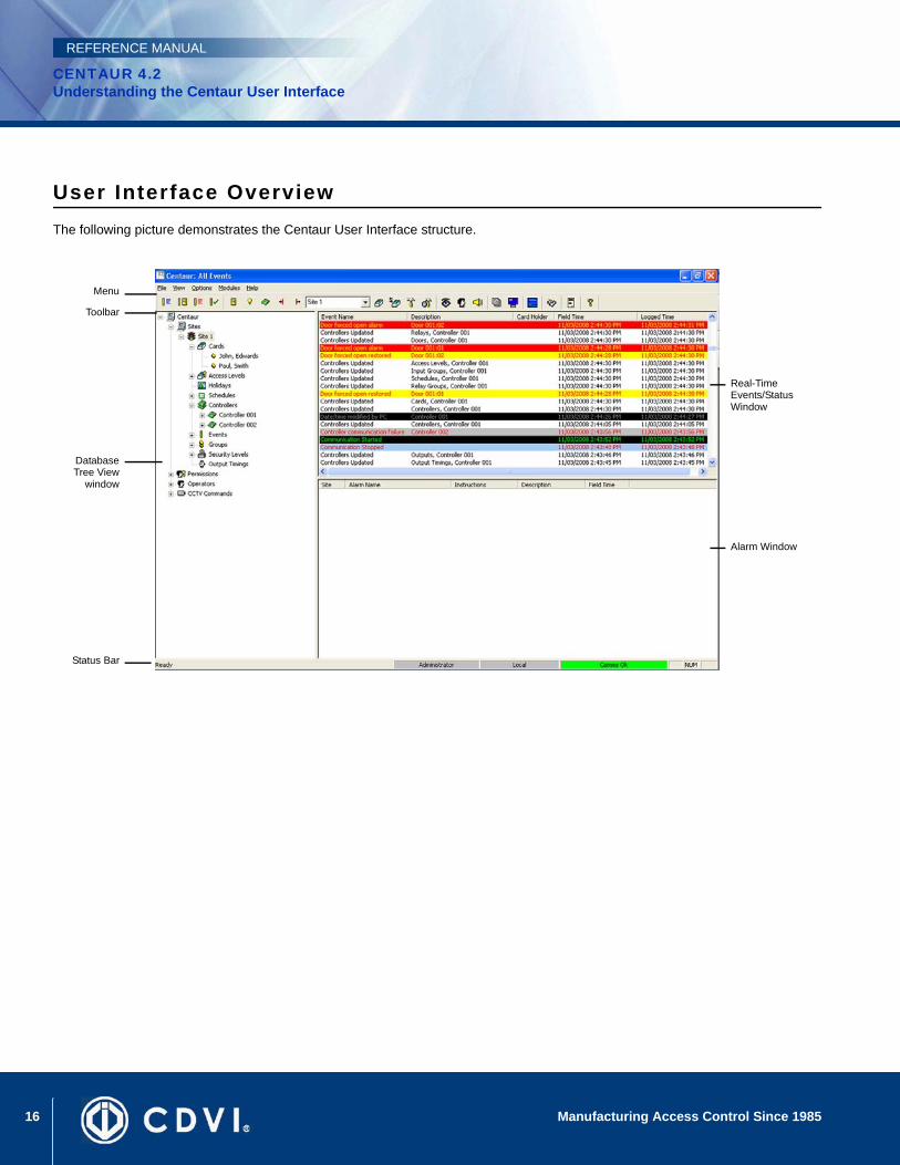
User Interface OverviewThe following picture demonstrates the Centaur User Interface structure.
DatabaseTree View
window
Alarm Window
Status Bar
Real-Time Events/Status Window
Toolbar
Menu
17Manufacturing Access Control Since 1985
CENTAUR 4.2Understanding the Centaur User Interface
REFERENCE MANUAL
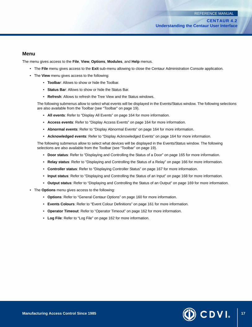
MenuThe menu gives access to the File, View, Options, Modules, and Help menus.
• The File menu gives access to the Exit sub-menu allowing to close the Centaur Administration Console application.
• The View menu gives access to the following:
• Toolbar: Allows to show or hide the Toolbar.
• Status Bar: Allows to show or hide the Status Bar.
• Refresh: Allows to refresh the Tree View and the Status windows.
The following submenus allow to select what events will be displayed in the Events/Status window. The following selections are also available from the Toolbar (see “Toolbar” on page 19).
• All events: Refer to “Display All Events” on page 164 for more information.
• Access events: Refer to “Display Access Events” on page 164 for more information.
• Abnormal events: Refer to “Display Abnormal Events” on page 164 for more information.
• Acknowledged events: Refer to “Display Acknowledged Events” on page 164 for more information.
The following submenus allow to select what devices will be displayed in the Events/Status window. The following selections are also available from the Toolbar (see “Toolbar” on page 19).
• Door status: Refer to “Displaying and Controlling the Status of a Door” on page 165 for more information.
• Relay status: Refer to “Displaying and Controlling the Status of a Relay” on page 166 for more information.
• Controller status: Refer to “Displaying Controller Status” on page 167 for more information.
• Input status: Refer to “Displaying and Controlling the Status of an Input” on page 168 for more information.
• Output status: Refer to “Displaying and Controlling the Status of an Output” on page 169 for more information.
• The Options menu gives access to the following:
• Options: Refer to “General Centaur Options” on page 160 for more information.
• Events Colours: Refer to “Event Colour Definitions” on page 161 for more information.
• Operator Timeout: Refer to “Operator Timeout” on page 162 for more information.
• Log File: Refer to “Log File” on page 162 for more information.

18 Manufacturing Access Control Since 1985
CENTAUR 4.2Understanding the Centaur User Interface
REFERENCE MANUAL
• The Modules menu gives access to the following:
• FontCard: Refer to “Centaur Card Management Feature” on page 96 for more information.
• Card Import/Export: Refer to “Centaur Card Import/Export Feature” on page 102 for more information.
• Database Management: Refer to “Database Management Module” on page 172 for more information.
• Database Backup Scheduler: Refer to “Database Backup Scheduler” on page 178 for more information.
• FrontGuard
• Locator
• WavePlayer: Refer to “Centaur Wave Player” on page 181 for more information.
• Pro-Report
• FrontView
• Diagnostic Tool
• Headcount
• The Help menu gives access to either the Centaur help file or the about Centaur page.
19Manufacturing Access Control Since 1985
CENTAUR 4.2Understanding the Centaur User Interface
REFERENCE MANUAL
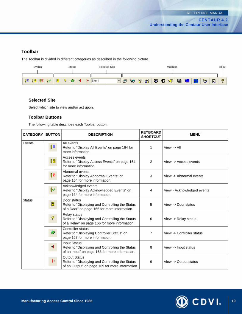
ToolbarThe Toolbar is divided in different categories as described in the following picture.
Selected SiteSelect which site to view and/or act upon.
Toolbar ButtonsThe following table describes each Toolbar button.
CATEGORY BUTTON DESCRIPTION KEYBOARDSHORTCUT MENU
Events All eventsRefer to “Display All Events” on page 164 for more information.
1 View -> All
Access eventsRefer to “Display Access Events” on page 164 for more information.
2 View -> Access events
Abnormal eventsRefer to “Display Abnormal Events” on page 164 for more information.
3 View -> Abnormal events
Acknowledged eventsRefer to “Display Acknowledged Events” on page 164 for more information.
4 View - Acknowledged events
Status Door statusRefer to “Displaying and Controlling the Status of a Door” on page 165 for more information.
5 View -> Door status
Relay statusRefer to “Displaying and Controlling the Status of a Relay” on page 166 for more information.
6 View -> Relay status
Controller statusRefer to “Displaying Controller Status” on page 167 for more information.
7 View -> Controller status
Input StatusRefer to “Displaying and Controlling the Status of an Input” on page 168 for more information.
8 View -> Input status
Output StatusRefer to “Displaying and Controlling the Status of an Output” on page 169 for more information.
9 View -> Output status
Events Status Selected Site AboutModules

20 Manufacturing Access Control Since 1985
CENTAUR 4.2Understanding the Centaur User Interface
REFERENCE MANUAL
Modules Open FontCardRefer to “Centaur Card Management Feature” on page 96 for more information.
Ctrl-F1 Module -> FrontCard
Open Card Import/ExportRefer to “Centaur Card Import/Export Feature” on page 102 for more information.
Ctrl-F2 Module -> Card import/Export
Open Database Management ModuleRefer to “Database Management Module” on page 172 for more information.
Ctrl-F3 Module -> Database Management
Open Database Backup SchedulerRefer to “Database Backup Scheduler” on page 178 for more information.
Ctrl-F4 Module -> Database Backup Scheduler
Open FrontGuardCtrl-F5 Module -> Front Guard
Open LocatorCtrl-F6 Module -> Locator
Open WavePlayerRefer to “Centaur Wave Player” on page 181 for more information.
Ctrl-F7 Module -> WavePlayer
Open Pro-ReportCtrl-F8 Module -> Pro-Report
Open FrontViewCtrl-F9 Module -> FrontView
Open Diagnostic ToolCtrl-F10 Module -> Diagnostic Tool
Open HeadcountCtrl-F11 Module -> Headcount
Open CMPPAllows loading or adding a card using a CMPP card enrolment station.
Ctrl-F12 Module -> CMPP
About AboutGives information about the Centaur Administration software, and CDVI Americas contact information.
CATEGORY BUTTON DESCRIPTION KEYBOARDSHORTCUT MENU
21Manufacturing Access Control Since 1985
CENTAUR 4.2Understanding the Centaur User Interface
REFERENCE MANUAL
Database Tree View WindowThe Database Tree View window located in the left-hand portion of your screen allows to create and configure a site including all its objects. From the Database Tree View window you can create and/or modify:
• “Sites” on page 23
• “Holidays” on page 39
• “Schedules” on page 43
• “Controllers” on page 49
• “Doors” on page 67
• “Access Levels” on page 83
• “Cards” on page 87
• “Elevator Control” on page 105
• “Relays” on page 109
• “Inputs” on page 115
• “Outputs” on page 125
• “Events” on page 133
• “Groups” on page 141
• “Security Levels” on page 150
• “Permissions” on page 151
• “Operators” on page 152
• “CCTV Commands” on page 155
Real-Time Events/Status WindowThe Real-Time Events/Status window lists all the events or device status for the selected site (see “Selected Site” on page 19). Use the View (See the View menu on page “Menu” on page 17) menu or the Toolbar button (See “Toolbar” on page 19) to select what you want to view in the Real-Time Events/Status window.
When All events, Access events, Abnormal events, or Acknowledged is selected, the Real-Time Events/Status window displays the following: Event Name, Description, Card holder, Field Time (date and time), and Logged Time.
When Door/Relay/Input/Output status is selected, the Real-Time Events/Status window displays the following: Door/Relay/Input/Output Name, Address, and Status.
When Controller status is selected, the Real-Time Events/Status window displays the following: Controller Name, Address, Status, Number of Cards, and Number of Errors.
Alarms WindowThe Alarms window lists all the alarms related to all sites. The Alarms window displays the following: Site, Alarm Name, Instructions, Description, and Field Time (date and time).
22 Manufacturing Access Control Since 1985
CENTAUR 4.2Understanding the Centaur User Interface
REFERENCE MANUAL
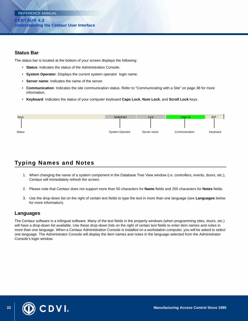
Status BarThe status bar is located at the bottom of your screen displays the following:
• Status: Indicates the status of the Administration Console.
• System Operator: Displays the current system operator login name.
• Server name: Indicates the name of the server.
• Communication: Indicates the site communication status. Refer to “Communicating with a Site” on page 38 for more information.
• Keyboard: Indicates the status of your computer keyboard Caps Lock, Num Lock, and Scroll Lock keys.
Typing Names and Notes
1. When changing the name of a system component in the Database Tree View window (i.e. controllers, events, doors, etc.), Centaur will immediately refresh the screen.
2. Please note that Centaur does not support more than 50 characters for Name fields and 255 characters for Notes fields.
3. Use the drop-down list on the right of certain text fields to type the text in more than one language (see Languages below for more information).
LanguagesThe Centaur software is a trilingual software. Many of the text fields in the property windows (when programming sites, doors, etc.) will have a drop-down list available. Use these drop-down lists on the right of certain text fields to enter item names and notes in more than one language. When a Centaur Administration Console is installed on a workstation computer, you will be asked to select one language. The Administrator Console will display the item names and notes in the language selected from the Administrator Console’s login window.
Status System Operator Server name Communication Keyboard
23
CENTAUR 4.2Access Control Software
Manufacturing Access Control Since 1985
REFERENCE MANUAL
Chapter 3: Sites
What Will I Find?Adding a Site . . . . . . . . . . . . . . . . . . . . . . . . . . . . . . . . . . . . . . . . . . . . . . . . . . . . . . . . . . . . . . . . . . . . . . . . . . . . . . . . . . . . . . . . . . . 24Modifying a Site . . . . . . . . . . . . . . . . . . . . . . . . . . . . . . . . . . . . . . . . . . . . . . . . . . . . . . . . . . . . . . . . . . . . . . . . . . . . . . . . . . . . . . . . . 27Deleting a Site . . . . . . . . . . . . . . . . . . . . . . . . . . . . . . . . . . . . . . . . . . . . . . . . . . . . . . . . . . . . . . . . . . . . . . . . . . . . . . . . . . . . . . . . . . 38Communicating with a Site . . . . . . . . . . . . . . . . . . . . . . . . . . . . . . . . . . . . . . . . . . . . . . . . . . . . . . . . . . . . . . . . . . . . . . . . . . . . . . . . 38
Each site can monitor and operate a specific number of cards, controllers, inputs, relays, and multi-function outputs, depending on the Centaur software edition being used.
The first step in setting up your system is creating and defining your sites. Once your sites have been defined you can begin programming the remaining items such as controllers, cards, schedules, and doors. In the Sites branch, local sites will be represented by a traffic light icon, remote (dial-up) sites will be represented by a telephone icon, and TCP/IP sites will be represented by a network icon depicting five computers.
24 Manufacturing Access Control Since 1985
CENTAUR 4.2Sites
REFERENCE MANUAL
Adding a SitePerform the following to add a site:
1. From the Database Tree View window (left-hand portion of your screen), right-click the Sites branch and click Add Site. You can also click the Sites branch and press the keyboard Insert key.
2. A dialogue box appears requesting if you would like to use the site configuration wizard. The site configuration wizard guides you through the minimum required settings to get the site communicating with its controllers. If you want to use the site configuration wizard, click Yes and follow the steps detailed in “Using the Site Configuration Wizard (Recommended)” on page 24. If you do not want to use the site configuration wizard, click No and go to step 3. If you do not want to add a site, click Cancel.
3. In the New Site window, type the desired site name. We recommend using a name that is representative of the site such as “Manufacturing Plant (Montreal)”.
4. Click OK.
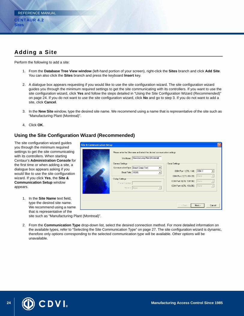
Using the Site Configuration Wizard (Recommended)The site configuration wizard guides you through the minimum required settings to get the site communicating with its controllers. When starting Centaur’s Administration Console for the first time or when adding a site, a dialogue box appears asking if you would like to use the site configuration wizard. If you click Yes, the Site & Communication Setup window appears.
1. In the Site Name text field, type the desired site name. We recommend using a name that is representative of the site such as “Manufacturing Plant (Montreal)”.
2. From the Communication Type drop-down list, select the desired connection method. For more detailed information on the available types, refer to “Selecting the Site Communication Type” on page 27. The site configuration wizard is dynamic, therefore only options corresponding to the selected communication type will be available. Other options will be unavailable.
25Manufacturing Access Control Since 1985
CENTAUR 4.2Sites
REFERENCE MANUAL
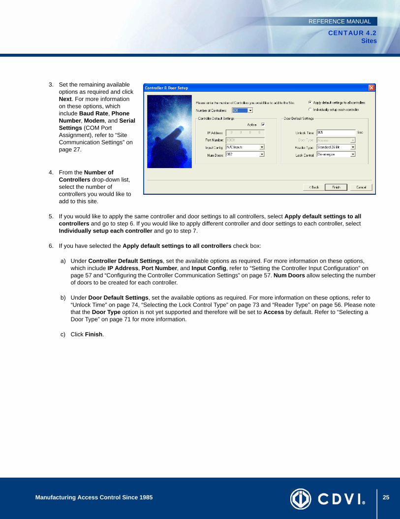
3. Set the remaining available options as required and click Next. For more information on these options, which include Baud Rate, Phone Number, Modem, and Serial Settings (COM Port Assignment), refer to “Site Communication Settings” on page 27.
4. From the Number of Controllers drop-down list, select the number of controllers you would like to add to this site.
5. If you would like to apply the same controller and door settings to all controllers, select Apply default settings to all controllers and go to step 6. If you would like to apply different controller and door settings to each controller, select Individually setup each controller and go to step 7.
6. If you have selected the Apply default settings to all controllers check box:
a) Under Controller Default Settings, set the available options as required. For more information on these options, which include IP Address, Port Number, and Input Config, refer to “Setting the Controller Input Configuration” on page 57 and “Configuring the Controller Communication Settings” on page 57. Num Doors allow selecting the number of doors to be created for each controller.
b) Under Door Default Settings, set the available options as required. For more information on these options, refer to “Unlock Time” on page 74, “Selecting the Lock Control Type” on page 73 and “Reader Type” on page 56. Please note that the Door Type option is not yet supported and therefore will be set to Access by default. Refer to “Selecting a Door Type” on page 71 for more information.
c) Click Finish.

26 Manufacturing Access Control Since 1985
CENTAUR 4.2Sites
REFERENCE MANUAL
7. If you have selected the Individually setup each controller check box:
a) Click Next.
b) Set the available options as required for each controller and click Next. For more information on these options, refer to “Controller Configuration” on page 55. To change the name of a controller, double click on the name of the controller that you want to edit and type the new name. Num Doors fields allow selecting the number of doors to be created for each controller.
c) Set the available options, which includes Door name, Reader Protocol, Lock Ctrl, and Unlock Time, as required for each door. For more information on these options, refer to “Door Settings” on page 71. To change the name of a door, double click on the name of the door that you want to edit and type the new name. To change the Unlock Time, double click on the value that need to be changed, and enter the new value in seconds. To change the Reader Protocol and/or the Lock Ctrl, click on the desired controller and select the new settings from the drop lists.
27Manufacturing Access Control Since 1985
CENTAUR 4.2Sites
REFERENCE MANUAL
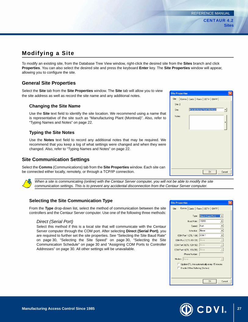
Modifying a SiteTo modify an existing site, from the Database Tree View window, right-click the desired site from the Sites branch and click Properties. You can also select the desired site and press the keyboard Enter key. The Site Properties window will appear, allowing you to configure the site.
General Site PropertiesSelect the Site tab from the Site Properties window. The Site tab will allow you to view the site address as well as record the site name and any additional notes.
Changing the Site NameUse the Site text field to identify the site location. We recommend using a name thatis representative of the site such as “Manufacturing Plant (Montreal)”. Also, refer to“Typing Names and Notes” on page 22.
Typing the Site NotesUse the Notes text field to record any additional notes that may be required. Werecommend that you keep a log of what settings were changed and when they werechanged. Also, refer to “Typing Names and Notes” on page 22.
Site Communication SettingsSelect the Comms (Communications) tab from the Site Properties window. Each site can be connected either locally, remotely, or through a TCP/IP connection.
Selecting the Site Communication TypeFrom the Type drop-down list, select the method of communication between the sitecontrollers and the Centaur Server computer. Use one of the following three methods:
Direct (Serial Port)Select this method if this is a local site that will communicate with the CentaurServer computer through the COM port. After selecting Direct (Serial Port), youare required to further set the site properties. See “Selecting the Site Baud Rate”on page 30, “Selecting the Site Speed” on page 30, “Selecting the SiteCommunication Schedule” on page 30 and “Assigning COM Ports to ControllerAddresses” on page 30. All other settings will be unavailable.
When a site is communicating (online) with the Centaur Server computer, you will not be able to modify the site communication settings. This is to prevent any accidental disconnection from the Centaur Server computer.
28 Manufacturing Access Control Since 1985
CENTAUR 4.2Sites
REFERENCE MANUAL
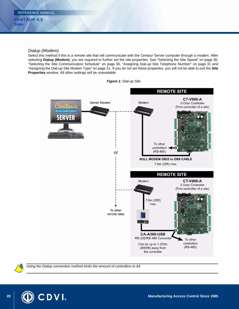
Dialup (Modem)Select this method if this is a remote site that will communicate with the Centaur Server computer through a modem. Afterselecting Dialup (Modem), you are required to further set the site properties. See “Selecting the Site Speed” on page 30,“Selecting the Site Communication Schedule” on page 30, “Assigning Dial-up Site Telephone Number” on page 31 and“Assigning the Dial-up Site Modem Type” on page 31. If you do not set these properties, you will not be able to exit the SiteProperties window. All other settings will be unavailable.
Figure 1: Dial-up Site
Using the Dialup connection method limits the amount of controllers to 64.
29Manufacturing Access Control Since 1985
CENTAUR 4.2Sites
REFERENCE MANUAL
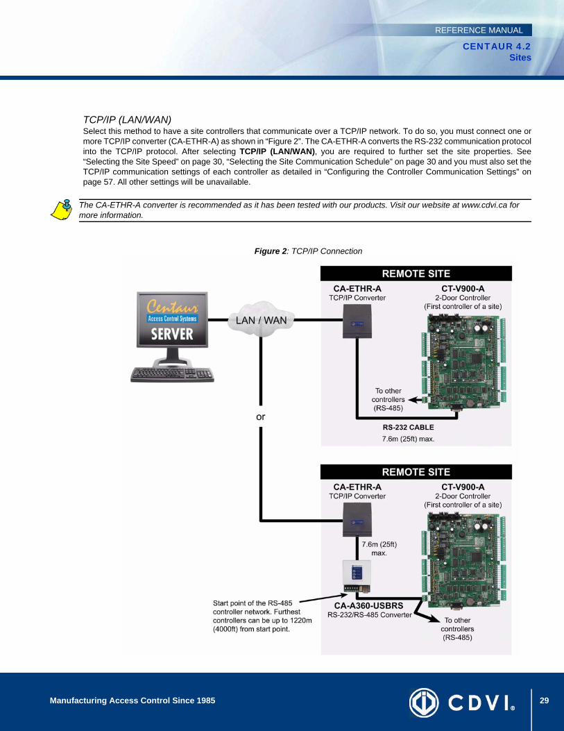
TCP/IP (LAN/WAN)Select this method to have a site controllers that communicate over a TCP/IP network. To do so, you must connect one ormore TCP/IP converter (CA-ETHR-A) as shown in “Figure 2”. The CA-ETHR-A converts the RS-232 communication protocolinto the TCP/IP protocol. After selecting TCP/IP (LAN/WAN), you are required to further set the site properties. See“Selecting the Site Speed” on page 30, “Selecting the Site Communication Schedule” on page 30 and you must also set theTCP/IP communication settings of each controller as detailed in “Configuring the Controller Communication Settings” onpage 57. All other settings will be unavailable.
Figure 2: TCP/IP Connection
The CA-ETHR-A converter is recommended as it has been tested with our products. Visit our website at www.cdvi.ca for more information.

30 Manufacturing Access Control Since 1985
CENTAUR 4.2Sites
REFERENCE MANUAL
Selecting the Site Baud RateIt is important that the baud rate be set to the same value that is defined by the dip switch settings of the controllers (thecontroller default setting is 19200 baud) in the site. Click the Baud Rate drop-down list, and then select the appropriate baudrate from the list. This setting will only be available if the selected communication type is Direct (Serial Port).
Selecting the Site SpeedClick the Speed drop-down list, then select the appropriate speed from the list. This setting defines the speed of data transferbetween the Centaur Server computer and the site controllers. During normal operation, the speed should be set to Fast.
Selecting the Site Communication ScheduleA site can be programmed to automatically communicate with the controllers (go online) according to a schedule. When theschedule becomes valid, the Centaur Server computer will automatically connect with the site until the schedule expires. Clickthe Schedule drop-down list and select the desired schedule from the list. For more information, refer to “Schedule Periods” onpage 45.
Assigning COM Ports to Controller AddressesEach site can support up to 256 controllers. The 256 controllers are divided into four controller loops of up to 64 controllerseach. Each of these loops must be assigned to a specific COM port.
• From the COM Port 1 (CTL 1-64) list, select a COM port. Controllers connected to the selected COM port will be assigned addresses 1 to 64 (controller’s DIP switch setting).
• From the COM Port 2 (CTL 65-128) list, select a COM port. Controllers connected to the selected COM port will be assigned addresses 65 to 128 (controller’s DIP switch setting + 64).
• From the COM Port 3 (CTL 129-192) list, select a COM port. Controllers connected to the selected COM port will be assigned addresses 129 to 192 (controller’s DIP switch setting + 128).
• From the COM Port 4 (CTL 193-256) list, select a COM port. Controllers connected to the selected COM port will be assigned addresses 193 to 256 (controller’s DIP switch setting + 192).
By limiting the number of controllers on the COM port, the speed of communication is increased. Also, refer to “Viewing theController Address” on page 52 for additional information on controller DIP switches and addresses. This setting will only beavailable if the selected communication type is Direct (Serial Port).
31Manufacturing Access Control Since 1985
CENTAUR 4.2Sites
REFERENCE MANUAL
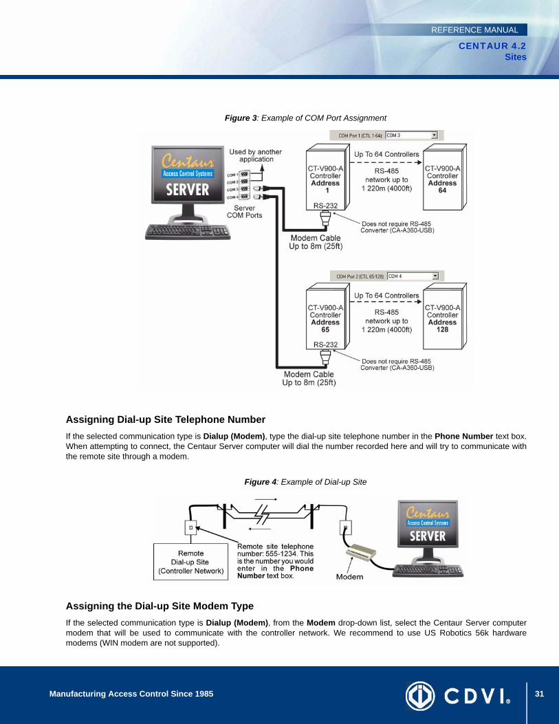
Figure 3: Example of COM Port Assignment
Assigning Dial-up Site Telephone NumberIf the selected communication type is Dialup (Modem), type the dial-up site telephone number in the Phone Number text box.When attempting to connect, the Centaur Server computer will dial the number recorded here and will try to communicate withthe remote site through a modem.
Figure 4: Example of Dial-up Site
Assigning the Dial-up Site Modem TypeIf the selected communication type is Dialup (Modem), from the Modem drop-down list, select the Centaur Server computermodem that will be used to communicate with the controller network. We recommend to use US Robotics 56k hardwaremodems (WIN modem are not supported).
32 Manufacturing Access Control Since 1985
CENTAUR 4.2Sites
REFERENCE MANUAL
Updating the Controller Time AutomaticallySelect the Update CTL time automatically every 15 minutes check box to download the date and time from the PC to allcontrollers in the site every 15 minutes. Clear the check box if you wish to disable automatic date and time update.
Enabling Offline Buffering (Outbox)Select the Enable Offline Buffering (Outbox) check box if you want Centaur to automatically store any system modificationsperformed while disconnected from the site (controllers offline) to an outbox table. Stored modifications are downloaded to thecontroller(s) next time communication is established with the site (controllers online). This check box is selected by default.
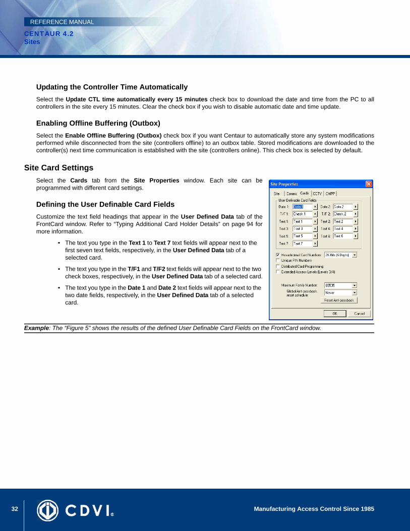
Site Card Settings Select the Cards tab from the Site Properties window. Each site can beprogrammed with different card settings.
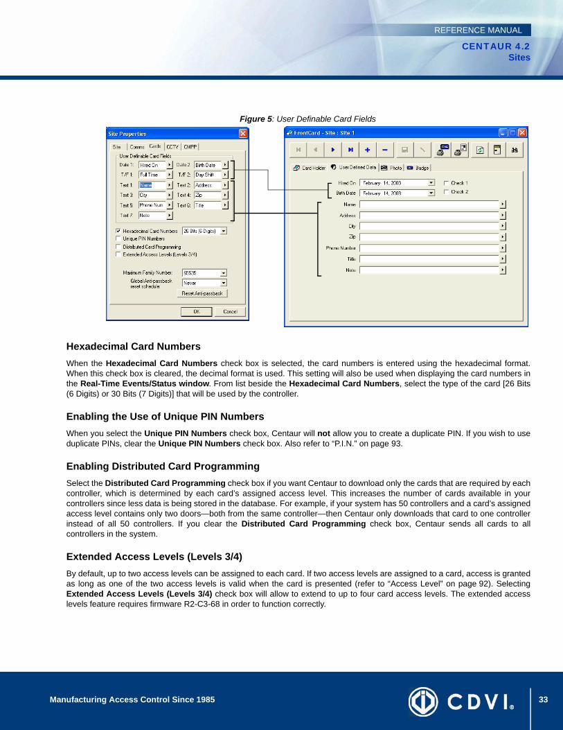
Defining the User Definable Card FieldsCustomize the text field headings that appear in the User Defined Data tab of theFrontCard window. Refer to “Typing Additional Card Holder Details” on page 94 formore information.
• The text you type in the Text 1 to Text 7 text fields will appear next to the first seven text fields, respectively, in the User Defined Data tab of a selected card.
• The text you type in the T/F1 and T/F2 text fields will appear next to the two check boxes, respectively, in the User Defined Data tab of a selected card.
• The text you type in the Date 1 and Date 2 text fields will appear next to the two date fields, respectively, in the User Defined Data tab of a selected card.
Example: The “Figure 5” shows the results of the defined User Definable Card Fields on the FrontCard window.
33Manufacturing Access Control Since 1985
CENTAUR 4.2Sites
REFERENCE MANUAL
Figure 5: User Definable Card Fields
Hexadecimal Card NumbersWhen the Hexadecimal Card Numbers check box is selected, the card numbers is entered using the hexadecimal format.When this check box is cleared, the decimal format is used. This setting will also be used when displaying the card numbers inthe Real-Time Events/Status window. From list beside the Hexadecimal Card Numbers, select the type of the card [26 Bits(6 Digits) or 30 Bits (7 Digits)] that will be used by the controller.
Enabling the Use of Unique PIN NumbersWhen you select the Unique PIN Numbers check box, Centaur will not allow you to create a duplicate PIN. If you wish to useduplicate PINs, clear the Unique PIN Numbers check box. Also refer to “P.I.N.” on page 93.
Enabling Distributed Card ProgrammingSelect the Distributed Card Programming check box if you want Centaur to download only the cards that are required by eachcontroller, which is determined by each card’s assigned access level. This increases the number of cards available in yourcontrollers since less data is being stored in the database. For example, if your system has 50 controllers and a card’s assignedaccess level contains only two doors—both from the same controller—then Centaur only downloads that card to one controllerinstead of all 50 controllers. If you clear the Distributed Card Programming check box, Centaur sends all cards to allcontrollers in the system.
Extended Access Levels (Levels 3/4)By default, up to two access levels can be assigned to each card. If two access levels are assigned to a card, access is grantedas long as one of the two access levels is valid when the card is presented (refer to “Access Level” on page 92). SelectingExtended Access Levels (Levels 3/4) check box will allow to extend to up to four card access levels. The extended accesslevels feature requires firmware R2-C3-68 in order to function correctly.
34 Manufacturing Access Control Since 1985
CENTAUR 4.2Sites
REFERENCE MANUAL
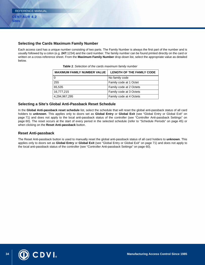
Selecting the Cards Maximum Family NumberEach access card has a unique number consisting of two parts. The Family Number is always the first part of the number and isusually followed by a colon (e.g. 247:1234) and the card number. The family number can be found printed directly on the card orwritten on a cross-reference sheet. From the Maximum Family Number drop-down list, select the appropriate value as detailedbelow.
Table 1: Selection of the cards maximum family number
Selecting a Site’s Global Anti-Passback Reset ScheduleIn the Global Anti-passback reset schedule list, select the schedule that will reset the global anti-passback status of all cardholders to unknown. This applies only to doors set as Global Entry or Global Exit (see “Global Entry or Global Exit” onpage 71) and does not apply to the local anti-passback status of the controller (see “Controller Anti-passback Settings” onpage 60). The reset occurs at the start of every period in the selected schedule (refer to “Schedule Periods” on page 45) orwhen clicking on the Reset Anti-passback button.
Reset Anti-passbackThe Reset Anti-passback button is used to manually reset the global anti-passback status of all card holders to unknown. Thisapplies only to doors set as Global Entry or Global Exit (see “Global Entry or Global Exit” on page 71) and does not apply tothe local anti-passback status of the controller (see “Controller Anti-passback Settings” on page 60).
MAXIMUM FAMILY NUMBER VALUE LENGTH OF THE FAMILY CODE
0 No family code255 Family code at 1 Octet65,535 Family code at 2 Octets16,777,215 Family code at 3 Octets4,294,967,295 Family code at 4 Octets
35Manufacturing Access Control Since 1985
CENTAUR 4.2Sites
REFERENCE MANUAL
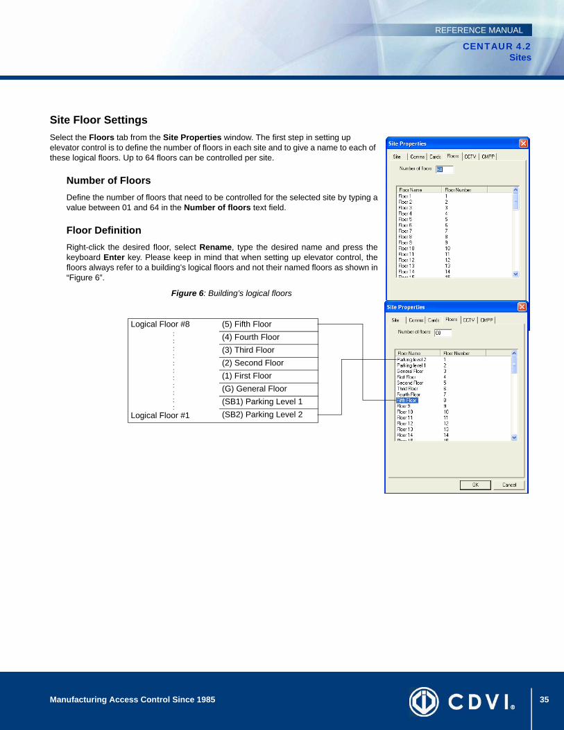
Site Floor SettingsSelect the Floors tab from the Site Properties window. The first step in setting up elevator control is to define the number of floors in each site and to give a name to each of these logical floors. Up to 64 floors can be controlled per site.
Number of FloorsDefine the number of floors that need to be controlled for the selected site by typing avalue between 01 and 64 in the Number of floors text field.
Floor DefinitionRight-click the desired floor, select Rename, type the desired name and press thekeyboard Enter key. Please keep in mind that when setting up elevator control, thefloors always refer to a building’s logical floors and not their named floors as shown in“Figure 6”.
Figure 6: Building’s logical floors
Logical Floor #8:::::::::::
Logical Floor #1
(5) Fifth Floor(4) Fourth Floor(3) Third Floor(2) Second Floor(1) First Floor(G) General Floor(SB1) Parking Level 1(SB2) Parking Level 2
36 Manufacturing Access Control Since 1985
CENTAUR 4.2Sites
REFERENCE MANUAL
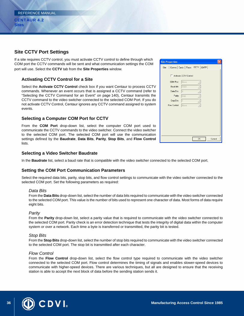
Site CCTV Port SettingsIf a site requires CCTV control, you must activate CCTV control to define through which COM port the CCTV commands will be sent and what communication settings the COM port will use. Select the CCTV tab from the Site Properties window.
Activating CCTV Control for a SiteSelect the Activate CCTV Control check box if you want Centaur to process CCTVcommands. Whenever an event occurs that is assigned a CCTV command (refer to“Selecting the CCTV Command for an Event” on page 140), Centaur transmits theCCTV command to the video switcher connected to the selected COM Port. If you donot activate CCTV Control, Centaur ignores any CCTV command assigned to systemevents.
Selecting a Computer COM Port for CCTVFrom the COM Port drop-down list, select the computer COM port used tocommunicate the CCTV commands to the video switcher. Connect the video switcherto the selected COM port. The selected COM port will use the communicationsettings defined by the Baudrate, Data Bits, Parity, Stop Bits, and Flow Controllists.
Selecting a Video Switcher BaudrateIn the Baudrate list, select a baud rate that is compatible with the video switcher connected to the selected COM port.
Setting the COM Port Communication ParametersSelect the required data bits, parity, stop bits, and flow control settings to communicate with the video switcher connected to theselected COM port. Set the following parameters as required:
Data BitsFrom the Data Bits drop-down list, select the number of data bits required to communicate with the video switcher connectedto the selected COM port. This value is the number of bits used to represent one character of data. Most forms of data requireeight bits.
ParityFrom the Parity drop-down list, select a parity value that is required to communicate with the video switcher connected tothe selected COM port. Parity check is an error detection technique that tests the integrity of digital data within the computersystem or over a network. Each time a byte is transferred or transmitted, the parity bit is tested.
Stop BitsFrom the Stop Bits drop-down list, select the number of stop bits required to communicate with the video switcher connectedto the selected COM port. The stop bit is transmitted after each character.
Flow ControlFrom the Flow Control drop-down list, select the flow control type required to communicate with the video switcherconnected to the selected COM port. Flow control determines the timing of signals and enables slower-speed devices tocommunicate with higher-speed devices. There are various techniques, but all are designed to ensure that the receivingstation is able to accept the next block of data before the sending station sends it.
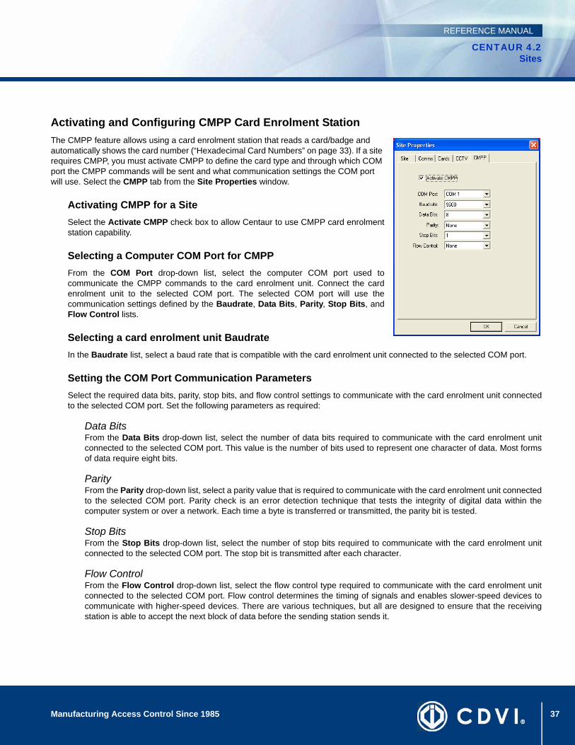
37Manufacturing Access Control Since 1985
CENTAUR 4.2Sites
REFERENCE MANUAL
Activating and Configuring CMPP Card Enrolment StationThe CMPP feature allows using a card enrolment station that reads a card/badge and automatically shows the card number (“Hexadecimal Card Numbers” on page 33). If a site requires CMPP, you must activate CMPP to define the card type and through which COM port the CMPP commands will be sent and what communication settings the COM port will use. Select the CMPP tab from the Site Properties window.
Activating CMPP for a SiteSelect the Activate CMPP check box to allow Centaur to use CMPP card enrolmentstation capability.
Selecting a Computer COM Port for CMPPFrom the COM Port drop-down list, select the computer COM port used tocommunicate the CMPP commands to the card enrolment unit. Connect the cardenrolment unit to the selected COM port. The selected COM port will use thecommunication settings defined by the Baudrate, Data Bits, Parity, Stop Bits, andFlow Control lists.
Selecting a card enrolment unit BaudrateIn the Baudrate list, select a baud rate that is compatible with the card enrolment unit connected to the selected COM port.
Setting the COM Port Communication ParametersSelect the required data bits, parity, stop bits, and flow control settings to communicate with the card enrolment unit connectedto the selected COM port. Set the following parameters as required:
Data BitsFrom the Data Bits drop-down list, select the number of data bits required to communicate with the card enrolment unitconnected to the selected COM port. This value is the number of bits used to represent one character of data. Most formsof data require eight bits.
ParityFrom the Parity drop-down list, select a parity value that is required to communicate with the card enrolment unit connectedto the selected COM port. Parity check is an error detection technique that tests the integrity of digital data within thecomputer system or over a network. Each time a byte is transferred or transmitted, the parity bit is tested.
Stop BitsFrom the Stop Bits drop-down list, select the number of stop bits required to communicate with the card enrolment unitconnected to the selected COM port. The stop bit is transmitted after each character.
Flow ControlFrom the Flow Control drop-down list, select the flow control type required to communicate with the card enrolment unitconnected to the selected COM port. Flow control determines the timing of signals and enables slower-speed devices tocommunicate with higher-speed devices. There are various techniques, but all are designed to ensure that the receivingstation is able to accept the next block of data before the sending station sends it.

38 Manufacturing Access Control Since 1985
CENTAUR 4.2Sites
REFERENCE MANUAL
Deleting a SiteTo delete an existing site, from the Database Tree View window, right-click the desired site from the Sites branch, and select Delete. You can also select the desired site and press the keyboard Delete key.
Communicating with a SiteIn order to communicate with a site, you must first successfully connect to the site (go online). To do so successfully, the appropriate connections between the controllers and the Centaur Server computer must be completed. Also, the site’s communication settings must be programmed appropriately as described in “Site Communication Settings” on page 27. The communication settings of each controller in the site must also be programmed appropriately as detailed in “Configuring the Controller Communication Settings” on page 57.
Connecting to a Site or Disconnecting from a SitePerform the following to connect (go online) to a site or disconnect (go offline) from a site:
1. From the Database Tree View window, right-click the desired site from the Sites branch, and click Connect or Disconnect.
2. Observe the communication status as demonstrated by the colour of the site Direct, Dial-Up, or TCP/IP icon in the Database Tree View window and the colour of the message in the status bar..
If you wish to connect to a site for continuous communication, select the Always schedule in the Comms tab of the Site Properties window. Refer to “Selecting the Site Communication Schedule” on page 30.
39
CENTAUR 4.2Access Control Software
Manufacturing Access Control Since 1985
REFERENCE MANUAL
Chapter 4: Holidays
What Will I Find?Adding a Holiday . . . . . . . . . . . . . . . . . . . . . . . . . . . . . . . . . . . . . . . . . . . . . . . . . . . . . . . . . . . . . . . . . . . . . . . . . . . . . . . . . . . . . . . . 40Modifying a Holiday . . . . . . . . . . . . . . . . . . . . . . . . . . . . . . . . . . . . . . . . . . . . . . . . . . . . . . . . . . . . . . . . . . . . . . . . . . . . . . . . . . . . . . 40Deleting a Holiday . . . . . . . . . . . . . . . . . . . . . . . . . . . . . . . . . . . . . . . . . . . . . . . . . . . . . . . . . . . . . . . . . . . . . . . . . . . . . . . . . . . . . . . 41
Use holidays to define which days in a specific schedule or period are valid or invalid. Once created, you can assign the holiday to one or more holiday groups.

40 Manufacturing Access Control Since 1985
CENTAUR 4.2Holidays
REFERENCE MANUAL
Adding a HolidayRight-click Holidays in the desired Site branch and click New Holiday. You can also click Holidays and press the keyboard Insert key to add a new holiday. After adding a holiday, the Holiday Properties window will appear, allowing you to configure the holiday (see “Holiday Settings” on page 40). Up to 128 holidays can be created in the system.
Modifying a HolidayFrom the desired Site branch in the Database Tree View window, right-click on the holiday you wish to modify, and click Properties. You can also click the desired holiday and press the keyboard Enter key. The Holiday Properties window will appear, allowing you to configure the holiday.
General Holiday PropertiesFrom the Holiday Properties window, select the Holiday tab. This allows you to view some of the system’s component addresses as well as record the holiday’s name and any additional notes.
Typing the Holiday NameUse the Name text field in the Holiday tab to identify the holiday. Werecommend using a name that is representative of the holiday such as NewYear’s Day. Also, refer to “Typing Names and Notes” on page 22.
Typing the Holiday NotesUse the Notes text field in the Holiday tab to record any additional notes thatmay be required. We recommend that you keep a log of which schedules havethis holiday selected. Also, refer to “Typing Names and Notes” on page 22.
Holiday SettingsYou can define which days in a year are holidays and then the holidays can be assigned to a holiday group. If you assign the holiday to one or more holiday groups, schedules are valid or invalid depending on how the holiday group is assigned to a schedule’s period (see “Schedule Periods” on page 45). If you do not assign a holiday to a holiday group, schedules are invalid (access denied) on that day.
Holiday group allows to group several holidays in one type.
Example: Christmas, New Year’s Day, and Labour Day are all days where the site is closed and card holders are denied access all day. These can be grouped as Holiday Group 1. Half-days such as Christmas Eve, and New Year’s Eve would be grouped as Holiday Group 2. Religious days would be grouped as Holiday Group 3.
41Manufacturing Access Control Since 1985
CENTAUR 4.2Holidays
REFERENCE MANUAL
Creating a Holiday and Assigning it to a Holiday GroupPerform the following to define the day, month, and year of the desired holiday.
1. From the Holiday Properties window, select the Details tab.
2. From the Day drop-down list, select a day from 1 to 31.
3. From the Month drop-down list, select a month from January to December.
4. From the Year drop-down list, select the desired year. If it is a holiday that occurs on the same month and day every year (e.g. New Year’s Day), select the Every Year option from the drop-down list.
5. If required, assign the holiday to the desired holiday group(s) by selecting the appropriate check box(es).
6. Click OK.
Deleting a HolidayTo delete an existing holiday, right-click the holiday from the appropriate Site branch in the Database Tree View window, and click Delete. You can also select the desired holiday and press the keyboard Delete key. A dialogue box will appear requesting confirmation.

42 Manufacturing Access Control Since 1985
CENTAUR 4.2Holidays
REFERENCE MANUAL
43
CENTAUR 4.2Access Control Software
Manufacturing Access Control Since 1985
REFERENCE MANUAL
Chapter 5: Schedules
What Will I Find?Adding a Schedule. . . . . . . . . . . . . . . . . . . . . . . . . . . . . . . . . . . . . . . . . . . . . . . . . . . . . . . . . . . . . . . . . . . . . . . . . . . . . . . . . . . . . . . 44 Modifying a Schedule . . . . . . . . . . . . . . . . . . . . . . . . . . . . . . . . . . . . . . . . . . . . . . . . . . . . . . . . . . . . . . . . . . . . . . . . . . . . . . . . . . . . 44Deleting a Schedule. . . . . . . . . . . . . . . . . . . . . . . . . . . . . . . . . . . . . . . . . . . . . . . . . . . . . . . . . . . . . . . . . . . . . . . . . . . . . . . . . . . . . . 47
A schedule can be used to schedule tasks, automate operations and to control access to doors, elevator floors, and much more. Schedules play an important role in the operation of many Centaur functions and are widely used throughout the software (see “Table 2” on page 44). A schedule is made up of up to eight time periods which determine when that schedule will be valid. Each period in a schedule specifies the days and times the schedule will be valid. For example, when programming doors, a schedule can be assigned to a specific door and the schedule will dictate when the door can be accessed without the use of a card.
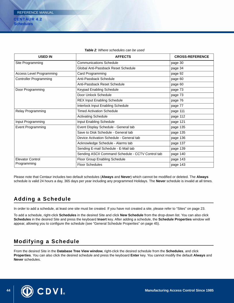
44 Manufacturing Access Control Since 1985
CENTAUR 4.2Schedules
REFERENCE MANUAL
Please note that Centaur includes two default schedules (Always and Never) which cannot be modified or deleted. The Always schedule is valid 24 hours a day, 365 days per year including any programmed Holidays. The Never schedule is invalid at all times.
Adding a ScheduleIn order to add a schedule, at least one site must be created. If you have not created a site, please refer to “Sites” on page 23.
To add a schedule, right-click Schedules in the desired Site and click New Schedule from the drop-down list. You can also click Schedules in the desired Site and press the keyboard Insert key. After adding a schedule, the Schedule Properties window will appear, allowing you to configure the schedule (see “General Schedule Properties” on page 45).
Modifying a ScheduleFrom the desired Site in the Database Tree View window, right-click the desired schedule from the Schedules, and click Properties. You can also click the desired schedule and press the keyboard Enter key. You cannot modify the default Always and Never schedules.
Table 2: Where schedules can be used
USED IN AFFECTS CROSS-REFERENCE
Site Programming Communications Schedule page 30Global Anti-Passback Reset Schedule page 34
Access Level Programming Card Programming page 92Controller Programming Anti-Passback Schedule page 60
Anti-Passback Reset Schedule page 60Door Programming Keypad Enabling Schedule page 73
Door Unlock Schedule page 73REX Input Enabling Schedule page 76Interlock Input Enabling Schedule page 77
Relay Programming Timed Activation Schedule page 111Activating Schedule page 112
Input Programming Input Enabling Schedule page 121Event Programming Event Display Schedule - General tab page 135
Save to Disk Schedule - General tab page 135Device Activation Schedule - General tab page 136Acknowledge Schedule - Alarms tab page 137Sending E-mail Schedule - E-Mail tab page 139Sending ASCII Command Schedule - CCTV Control tab page 140
Elevator Control Programming
Floor Group Enabling Schedule page 143Floor Schedules page 143
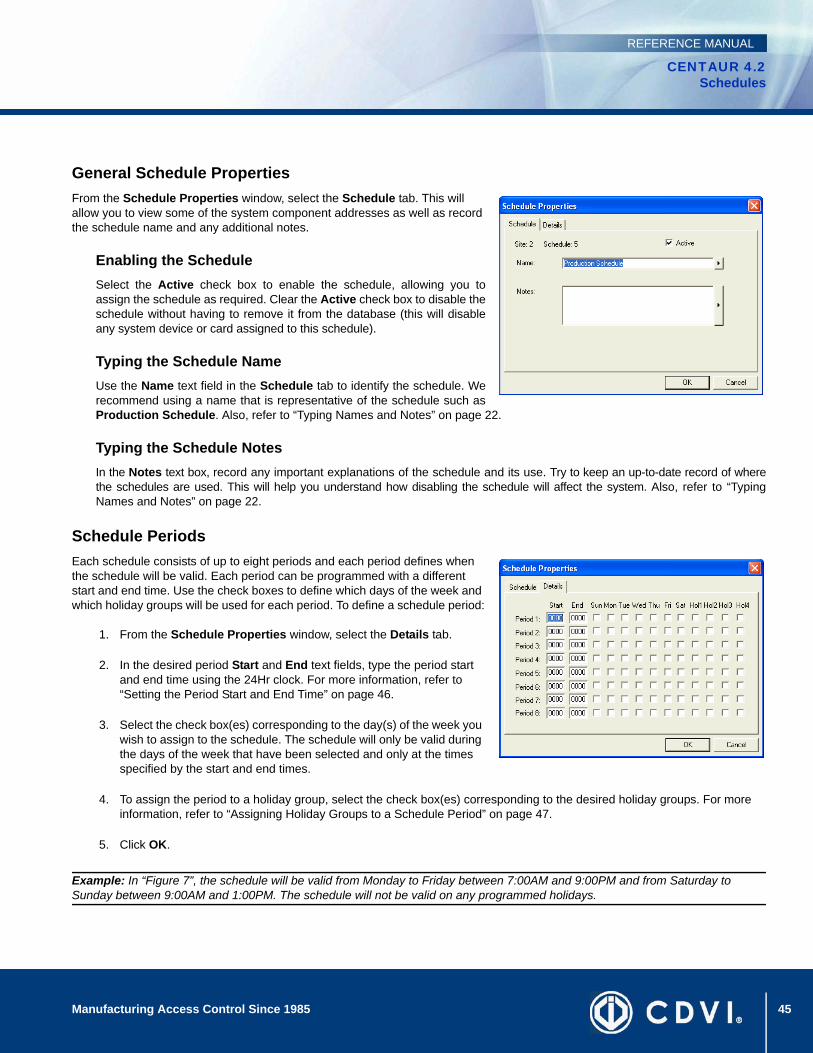
45Manufacturing Access Control Since 1985
CENTAUR 4.2Schedules
REFERENCE MANUAL
General Schedule PropertiesFrom the Schedule Properties window, select the Schedule tab. This will allow you to view some of the system component addresses as well as record the schedule name and any additional notes.
Enabling the ScheduleSelect the Active check box to enable the schedule, allowing you toassign the schedule as required. Clear the Active check box to disable theschedule without having to remove it from the database (this will disableany system device or card assigned to this schedule).
Typing the Schedule NameUse the Name text field in the Schedule tab to identify the schedule. Werecommend using a name that is representative of the schedule such asProduction Schedule. Also, refer to “Typing Names and Notes” on page 22.
Typing the Schedule NotesIn the Notes text box, record any important explanations of the schedule and its use. Try to keep an up-to-date record of wherethe schedules are used. This will help you understand how disabling the schedule will affect the system. Also, refer to “TypingNames and Notes” on page 22.
Schedule PeriodsEach schedule consists of up to eight periods and each period defines when the schedule will be valid. Each period can be programmed with a different start and end time. Use the check boxes to define which days of the week and which holiday groups will be used for each period. To define a schedule period:
1. From the Schedule Properties window, select the Details tab.
2. In the desired period Start and End text fields, type the period start and end time using the 24Hr clock. For more information, refer to “Setting the Period Start and End Time” on page 46.
3. Select the check box(es) corresponding to the day(s) of the week you wish to assign to the schedule. The schedule will only be valid during the days of the week that have been selected and only at the times specified by the start and end times.
4. To assign the period to a holiday group, select the check box(es) corresponding to the desired holiday groups. For more information, refer to “Assigning Holiday Groups to a Schedule Period” on page 47.
5. Click OK.
Example: In “Figure 7”, the schedule will be valid from Monday to Friday between 7:00AM and 9:00PM and from Saturday to Sunday between 9:00AM and 1:00PM. The schedule will not be valid on any programmed holidays.
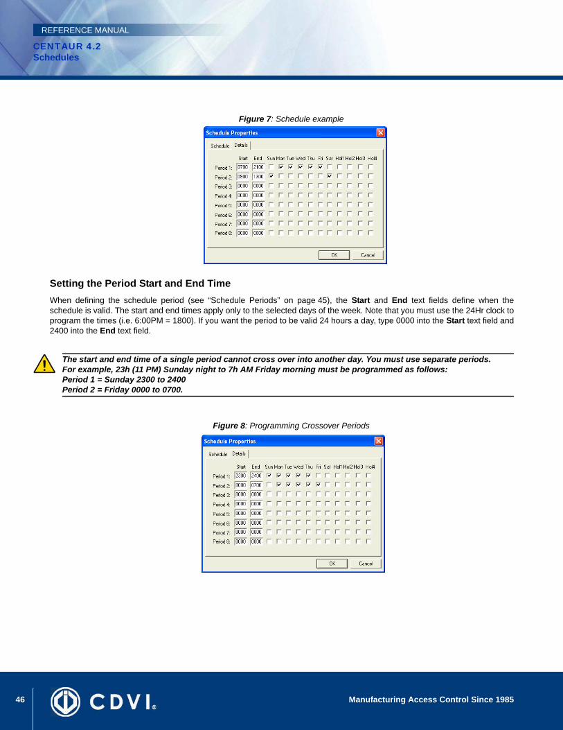
46 Manufacturing Access Control Since 1985
CENTAUR 4.2Schedules
REFERENCE MANUAL
Figure 7: Schedule example
Setting the Period Start and End Time When defining the schedule period (see “Schedule Periods” on page 45), the Start and End text fields define when theschedule is valid. The start and end times apply only to the selected days of the week. Note that you must use the 24Hr clock toprogram the times (i.e. 6:00PM = 1800). If you want the period to be valid 24 hours a day, type 0000 into the Start text field and2400 into the End text field.
Figure 8: Programming Crossover Periods
The start and end time of a single period cannot cross over into another day. You must use separate periods. For example, 23h (11 PM) Sunday night to 7h AM Friday morning must be programmed as follows:Period 1 = Sunday 2300 to 2400 Period 2 = Friday 0000 to 0700.
47Manufacturing Access Control Since 1985
CENTAUR 4.2Schedules
REFERENCE MANUAL
Assigning Holiday Groups to a Schedule PeriodWhen defining the schedule’s periods (see “Schedule Periods” on page 45), select the Hol1, Hol2, Hol3, and Hol4 check boxesto assign any of the site holiday groups to one or more periods within the schedule. For more information on holidays, refer to“Creating a Holiday and Assigning it to a Holiday Group” on page 41. Holiday groups function as follows:
• When you clear a holiday group check box, the schedule’s period is invalid during holidays assigned to that holiday group.
• When you select a holiday group check box, the schedule’s period is valid between its start and end time on any holidays assigned to that holiday group, even if the holiday falls on a day that is not enabled in the schedule’s period.
• To create a different start and end time period for holidays only (a holiday schedule), assign the holiday group to a separate (new) period. Set the start and end time, but do not select any of the “day” check boxes (Sun to Sat).
Deleting a ScheduleTo delete an existing schedule, right-click the schedule from the Schedules and click Delete. You can also click the desired schedule from the Schedules and press the keyboard Delete key. A dialogue box will appear requesting confirmation. You cannot delete the default Always and Never schedules. You cannot delete a schedule assigned/used in other parts of the system such as access levels, door schedules, etc.

48 Manufacturing Access Control Since 1985
CENTAUR 4.2Schedules
REFERENCE MANUAL
49
CENTAUR 4.2Access Control Software
Manufacturing Access Control Since 1985
REFERENCE MANUAL
Chapter 6: Controllers
What Will I Find?Adding Controllers . . . . . . . . . . . . . . . . . . . . . . . . . . . . . . . . . . . . . . . . . . . . . . . . . . . . . . . . . . . . . . . . . . . . . . . . . . . . . . . . . . . . . . . 50 Modifying a Controller . . . . . . . . . . . . . . . . . . . . . . . . . . . . . . . . . . . . . . . . . . . . . . . . . . . . . . . . . . . . . . . . . . . . . . . . . . . . . . . . . . . . 52Deleting a Controller . . . . . . . . . . . . . . . . . . . . . . . . . . . . . . . . . . . . . . . . . . . . . . . . . . . . . . . . . . . . . . . . . . . . . . . . . . . . . . . . . . . . . 62Online Controller Firmware Upgrades . . . . . . . . . . . . . . . . . . . . . . . . . . . . . . . . . . . . . . . . . . . . . . . . . . . . . . . . . . . . . . . . . . . . . . . . 63Download. . . . . . . . . . . . . . . . . . . . . . . . . . . . . . . . . . . . . . . . . . . . . . . . . . . . . . . . . . . . . . . . . . . . . . . . . . . . . . . . . . . . . . . . . . . . . . 64Other Controller Management Options . . . . . . . . . . . . . . . . . . . . . . . . . . . . . . . . . . . . . . . . . . . . . . . . . . . . . . . . . . . . . . . . . . . . . . . 65
Controllers are the heart of the Centaur access control system. The database is distributed to all controllers allowing them to make decisions in a fraction of a second, whether or not the managing computer is online. These controllers also feature online upgradable firmware and a real-time clock.
Program each controller individually by defining its door input and output configuration as well as setting its anti-passback options. For additional communication settings, refer to “Sites” on page 23. Each site can support up to 256 controllers.
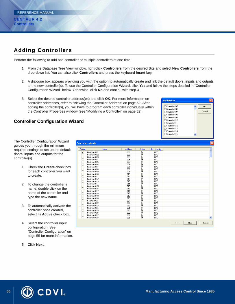
50 Manufacturing Access Control Since 1985
CENTAUR 4.2Controllers
REFERENCE MANUAL
Adding ControllersPerform the following to add one controller or multiple controllers at one time:
1. From the Database Tree View window, right-click Controllers from the desired Site and select New Controllers from the drop-down list. You can also click Controllers and press the keyboard Insert key.
2. A dialogue box appears providing you with the option to automatically create and link the default doors, inputs and outputs to the new controller(s). To use the Controller Configuration Wizard, click Yes and follow the steps detailed in “Controller Configuration Wizard” below. Otherwise, click No and continu with step 3.
3. Select the desired controller address(es) and click OK. For more information on controller addresses, refer to “Viewing the Controller Address” on page 52. After adding the controller(s), you will have to program each controller individually within the Controller Properties window (see “Modifying a Controller” on page 52).
Controller Configuration Wizard
The Controller Configuration Wizard guides you through the minimum required settings to set up the default doors, inputs and outputs for the controller(s).
1. Check the Create check box for each controller you want to create.
2. To change the controller’s name, double click on the name of the controller and type the new name.
3. To automatically activate the controller once created, select its Active check box.
4. Select the controller input configuration. See “Controller Configuration” on page 55 for more information.
5. Click Next.
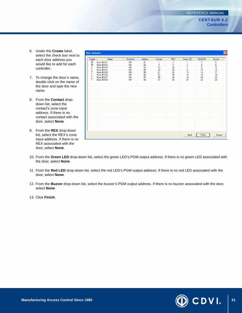
51Manufacturing Access Control Since 1985
CENTAUR 4.2Controllers
REFERENCE MANUAL
6. Under the Create label, select the check box next to each door address you would like to add for each controller.
7. To change the door’s name, double click on the name of the door and type the new name.
8. From the Contact drop-down list, select the contact’s zone input address. If there is no contact associated with the door, select None.
9. From the REX drop-down list, select the REX’s zone input address. If there is no REX associated with the door, select None.
10. From the Green LED drop-down list, select the green LED’s PGM output address. If there is no green LED associated with the door, select None.
11. From the Red LED drop-down list, select the red LED’s PGM output address. If there is no red LED associated with the door, select None.
12. From the Buzzer drop-down list, select the buzzer’s PGM output address. If there is no buzzer associated with the door, select None.
13. Click Finish.
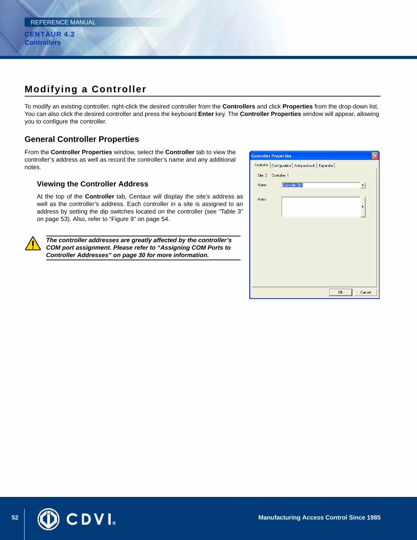
52 Manufacturing Access Control Since 1985
CENTAUR 4.2Controllers
REFERENCE MANUAL
Modifying a ControllerTo modify an existing controller, right-click the desired controller from the Controllers and click Properties from the drop-down list. You can also click the desired controller and press the keyboard Enter key. The Controller Properties window will appear, allowing you to configure the controller.
General Controller PropertiesFrom the Controller Properties window, select the Controller tab to view the controller’s address as well as record the controller’s name and any additional notes.
Viewing the Controller AddressAt the top of the Controller tab, Centaur will display the site’s address aswell as the controller’s address. Each controller in a site is assigned to anaddress by setting the dip switches located on the controller (see “Table 3”on page 53). Also, refer to “Figure 9” on page 54.
The controller addresses are greatly affected by the controller’s COM port assignment. Please refer to “Assigning COM Ports to Controller Addresses” on page 30 for more information.
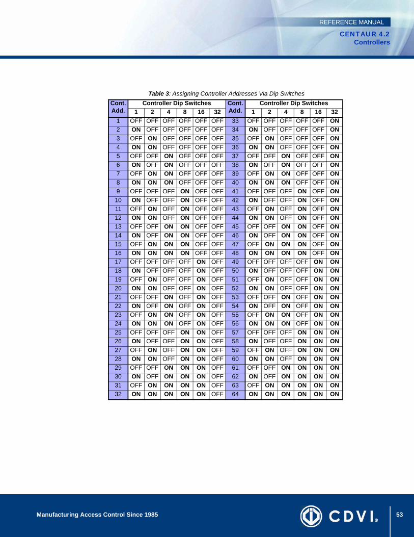
53Manufacturing Access Control Since 1985
CENTAUR 4.2Controllers
REFERENCE MANUAL
Table 3: Assigning Controller Addresses Via Dip Switches
Cont.Add.
Controller Dip Switches Cont.Add.
Controller Dip Switches1 2 4 8 16 32 1 2 4 8 16 32
1 OFF OFF OFF OFF OFF OFF 33 OFF OFF OFF OFF OFF ON2 ON OFF OFF OFF OFF OFF 34 ON OFF OFF OFF OFF ON3 OFF ON OFF OFF OFF OFF 35 OFF ON OFF OFF OFF ON4 ON ON OFF OFF OFF OFF 36 ON ON OFF OFF OFF ON5 OFF OFF ON OFF OFF OFF 37 OFF OFF ON OFF OFF ON6 ON OFF ON OFF OFF OFF 38 ON OFF ON OFF OFF ON7 OFF ON ON OFF OFF OFF 39 OFF ON ON OFF OFF ON8 ON ON ON OFF OFF OFF 40 ON ON ON OFF OFF ON9 OFF OFF OFF ON OFF OFF 41 OFF OFF OFF ON OFF ON
10 ON OFF OFF ON OFF OFF 42 ON OFF OFF ON OFF ON11 OFF ON OFF ON OFF OFF 43 OFF ON OFF ON OFF ON12 ON ON OFF ON OFF OFF 44 ON ON OFF ON OFF ON13 OFF OFF ON ON OFF OFF 45 OFF OFF ON ON OFF ON14 ON OFF ON ON OFF OFF 46 ON OFF ON ON OFF ON15 OFF ON ON ON OFF OFF 47 OFF ON ON ON OFF ON16 ON ON ON ON OFF OFF 48 ON ON ON ON OFF ON17 OFF OFF OFF OFF ON OFF 49 OFF OFF OFF OFF ON ON18 ON OFF OFF OFF ON OFF 50 ON OFF OFF OFF ON ON19 OFF ON OFF OFF ON OFF 51 OFF ON OFF OFF ON ON20 ON ON OFF OFF ON OFF 52 ON ON OFF OFF ON ON21 OFF OFF ON OFF ON OFF 53 OFF OFF ON OFF ON ON22 ON OFF ON OFF ON OFF 54 ON OFF ON OFF ON ON23 OFF ON ON OFF ON OFF 55 OFF ON ON OFF ON ON24 ON ON ON OFF ON OFF 56 ON ON ON OFF ON ON25 OFF OFF OFF ON ON OFF 57 OFF OFF OFF ON ON ON26 ON OFF OFF ON ON OFF 58 ON OFF OFF ON ON ON27 OFF ON OFF ON ON OFF 59 OFF ON OFF ON ON ON28 ON ON OFF ON ON OFF 60 ON ON OFF ON ON ON29 OFF OFF ON ON ON OFF 61 OFF OFF ON ON ON ON30 ON OFF ON ON ON OFF 62 ON OFF ON ON ON ON31 OFF ON ON ON ON OFF 63 OFF ON ON ON ON ON32 ON ON ON ON ON OFF 64 ON ON ON ON ON ON
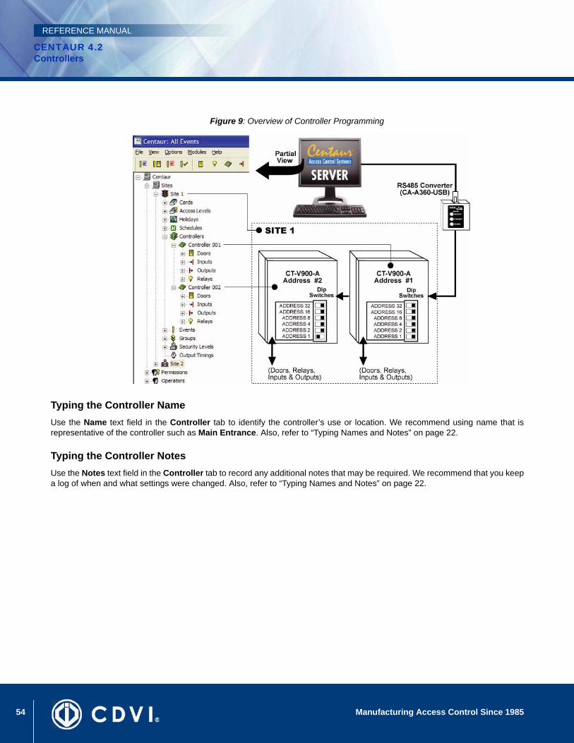
54 Manufacturing Access Control Since 1985
CENTAUR 4.2Controllers
REFERENCE MANUAL
Figure 9: Overview of Controller Programming
Typing the Controller NameUse the Name text field in the Controller tab to identify the controller’s use or location. We recommend using name that isrepresentative of the controller such as Main Entrance. Also, refer to “Typing Names and Notes” on page 22.
Typing the Controller NotesUse the Notes text field in the Controller tab to record any additional notes that may be required. We recommend that you keepa log of when and what settings were changed. Also, refer to “Typing Names and Notes” on page 22.
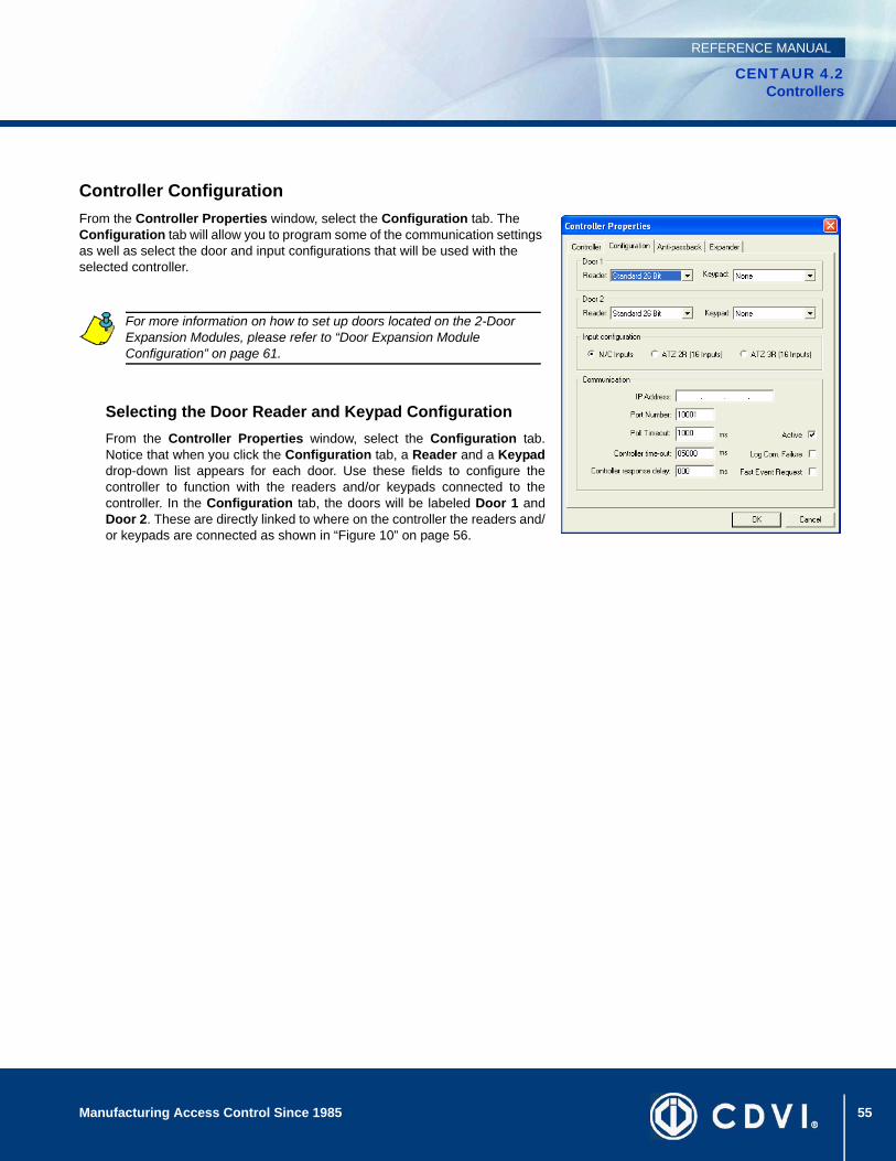
55Manufacturing Access Control Since 1985
CENTAUR 4.2Controllers
REFERENCE MANUAL
Controller ConfigurationFrom the Controller Properties window, select the Configuration tab. The Configuration tab will allow you to program some of the communication settings as well as select the door and input configurations that will be used with the selected controller.
Selecting the Door Reader and Keypad ConfigurationFrom the Controller Properties window, select the Configuration tab.Notice that when you click the Configuration tab, a Reader and a Keypaddrop-down list appears for each door. Use these fields to configure thecontroller to function with the readers and/or keypads connected to thecontroller. In the Configuration tab, the doors will be labeled Door 1 andDoor 2. These are directly linked to where on the controller the readers and/or keypads are connected as shown in “Figure 10” on page 56.
For more information on how to set up doors located on the 2-Door Expansion Modules, please refer to “Door Expansion Module Configuration” on page 61.

56 Manufacturing Access Control Since 1985
CENTAUR 4.2Controllers
REFERENCE MANUAL
Figure 10: Controller’s Door Configuration
Reader TypeFrom the Reader drop-down list, select the type of reader used. If no reader is being used on the selected door, select None.
Keypad TypeFrom the Keypad drop-down list, select the type of keypad used. If the controller’s door is not using a keypad, select None.When both a reader and a keypad are used, only card holders with the Use Keypad option enabled (see “Use Keypad” onpage 93) have to use both to gain access.
57Manufacturing Access Control Since 1985
CENTAUR 4.2Controllers
REFERENCE MANUAL
Setting the Controller Input ConfigurationEach controller has eight inputs that can be doubled to 16 and each 2-Door Expansion Module (CA-A470-A) has four inputs.This means that the controller can monitor the state of up to 28 input devices. These inputs can be used to monitor devices suchas magnetic contacts, motion detectors, and temperature sensors. Under Input Configuration, select one of the three followinginput configuration radio buttons. The selected input configuration applies to the controller’s inputs and the inputs located on thecontroller’s 2-Door Expansion Modules.
NC InputsThis setup will not support tamper and wire fault (short circuit) recognition, but will generate an alarm condition when thestate of the input is breached. All inputs on the selected controller and its 2-Door Expansion Modules must be connectedusing the NC Input Connection Method described in “NC Input Connection” on page 116.
ATZ 2R (16 Inputs)This setup will not support wire fault (short circuit) recognition, but will generate an alarm condition when the state of theinput is breached. This method also requires the connection of two devices to each controller’s input for a total of 16 inputs.The 2-Door Expansion Modules do not support input doubling. All inputs on the selected controller and its 2-Door ExpansionModules must be connected using the ATZ 2R Input Connection Methods described in “ATZ 2R Connection” on page 117.
ATZ 3R (16 Inputs)This setup generates an alarm condition when the state of the input is breached. An alarm condition is also generated whena wire fault (short circuit) occurs. This method requires the connection of two devices to each controller’s input for a total of16 inputs. The 2-Door Expansion Modules do not support input doubling. All inputs on the selected controller and its 2-DoorExpansion Modules must be connected as described in “ATZ 3R Connection Method” on page 118.
Configuring the Controller Communication SettingsUnder Communication, configure the controller’s communication settings.
IP Address and Port NumberThe IP Address and Port Number text fields are available only if the selected communication type is TCP/IP (LAN/WAN)as described in “Selecting the Site Communication Type” on page 27. Before entering this data, you need a “static” IPaddress and port number for each CA-ETHR-A, which should be provided by your Network Administrator. You will then needto program each CA-ETHR-A with an IP address and a port number. In the IP Address and Port Number text fields, typethe IP address and port number programmed into the CA-ETHR-A device that is connected to the controller. If there areseveral controllers wired to one CA-ETHR-A device, then each controller on that loop must be programmed with the sameIP address as detailed in the example below.
The first time you program a CA-ETHR-A, it will be done via a serial port using a null modem cable. To initiate acommunication with the CA-ETHR-A, press the reset button and type postech with in 5 seconds, if you pass this delay youwon’t be able to log in. Once programmed, you will be able to access the configurations easily by using a web browser andsimply typing in the IP address. To program the Port #, the range is from 1 - 65535, however do not use 21, 25, 8, or 110 asthey are reserved. For further details please consult the CA-ETHR-A Installation Guide.

58 Manufacturing Access Control Since 1985
CENTAUR 4.2Controllers
REFERENCE MANUAL
Example: In “Figure 11”, the IP Address for controller #1 and #2 would be 10.10.10.2 and the IP Address for controller #3and #4 would be 10.10.10.3. The port number for controller #1 and #2 would be 10001 and the port number for controller#3 and #4 would be 10001.
Figure 11: Example of TCP/IP Controller Settings
59Manufacturing Access Control Since 1985
CENTAUR 4.2Controllers
REFERENCE MANUAL
Poll TimeoutThe Poll Timeout text field appears only if the selected communication type is TCP/IP (LAN/WAN) as described in“Selecting the Site Communication Type” on page 27. Depending on network traffic, you may need to increase this value toimprove communication speed between the Centaur Server and the controllers. In the Poll Timeout text field, type a valuebetween 500 and 5000 milliseconds.
ActiveWhen the Active check box is selected, communication between the Centaur Server and the controller is possible. Clearthe Active check box to cancel any communication between the controller and the Centaur Server.
Controller TimeoutEnter the length of time the controller will wait for a response from the Centaur Server before generating a CommunicationFailure locally at the controller.
Log Com. FailureWhen the Log Com. Failure check box is selected, Communication Failures between the controller and the Centaur Serverare logged.
Controller Response DelayIn the Controller response delay text field, type the amount of time (1 to 255 milliseconds) that the controller will wait beforeresponding to a command from the Centaur Server.
Fast Event RequestWhen the Fast Event Request check box is selected, the event upload rate is increased in order to prevent lost of events.
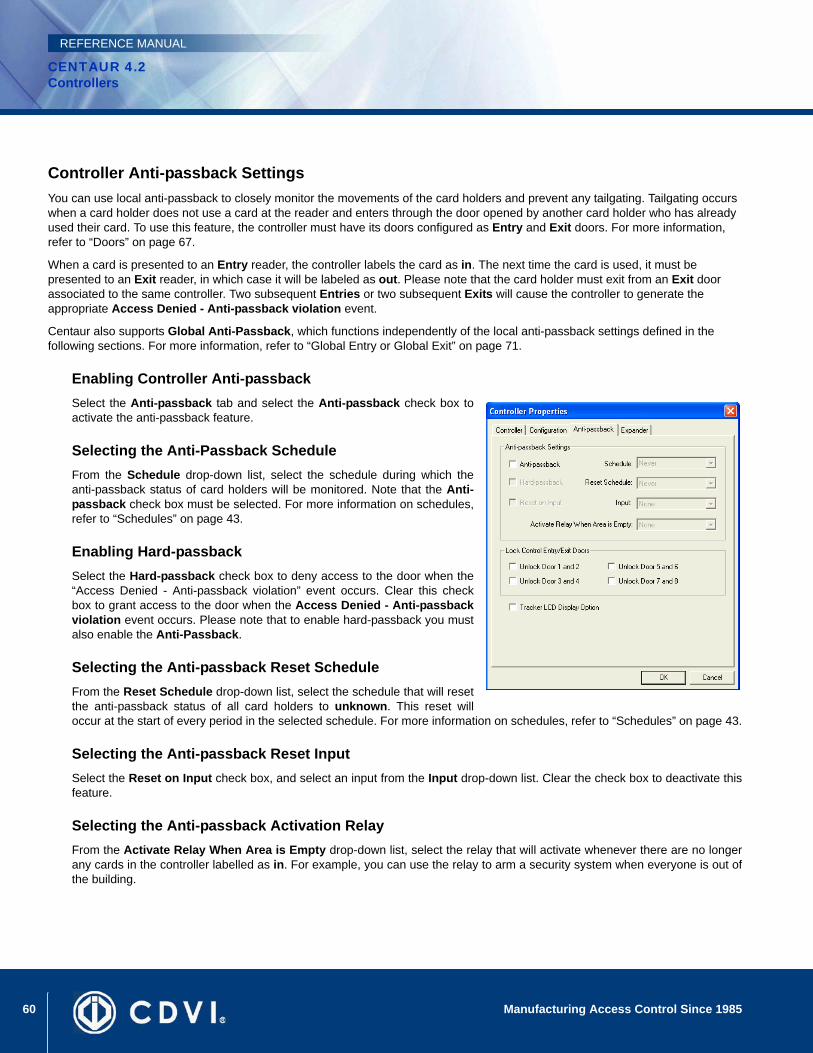
60 Manufacturing Access Control Since 1985
CENTAUR 4.2Controllers
REFERENCE MANUAL
Controller Anti-passback SettingsYou can use local anti-passback to closely monitor the movements of the card holders and prevent any tailgating. Tailgating occurs when a card holder does not use a card at the reader and enters through the door opened by another card holder who has already used their card. To use this feature, the controller must have its doors configured as Entry and Exit doors. For more information, refer to “Doors” on page 67.
When a card is presented to an Entry reader, the controller labels the card as in. The next time the card is used, it must be presented to an Exit reader, in which case it will be labeled as out. Please note that the card holder must exit from an Exit door associated to the same controller. Two subsequent Entries or two subsequent Exits will cause the controller to generate the appropriate Access Denied - Anti-passback violation event.
Centaur also supports Global Anti-Passback, which functions independently of the local anti-passback settings defined in the following sections. For more information, refer to “Global Entry or Global Exit” on page 71.
Enabling Controller Anti-passbackSelect the Anti-passback tab and select the Anti-passback check box toactivate the anti-passback feature.
Selecting the Anti-Passback ScheduleFrom the Schedule drop-down list, select the schedule during which theanti-passback status of card holders will be monitored. Note that the Anti-passback check box must be selected. For more information on schedules,refer to “Schedules” on page 43.
Enabling Hard-passbackSelect the Hard-passback check box to deny access to the door when the“Access Denied - Anti-passback violation” event occurs. Clear this checkbox to grant access to the door when the Access Denied - Anti-passbackviolation event occurs. Please note that to enable hard-passback you mustalso enable the Anti-Passback.
Selecting the Anti-passback Reset ScheduleFrom the Reset Schedule drop-down list, select the schedule that will resetthe anti-passback status of all card holders to unknown. This reset willoccur at the start of every period in the selected schedule. For more information on schedules, refer to “Schedules” on page 43.
Selecting the Anti-passback Reset InputSelect the Reset on Input check box, and select an input from the Input drop-down list. Clear the check box to deactivate thisfeature.
Selecting the Anti-passback Activation RelayFrom the Activate Relay When Area is Empty drop-down list, select the relay that will activate whenever there are no longerany cards in the controller labelled as in. For example, you can use the relay to arm a security system when everyone is out ofthe building.
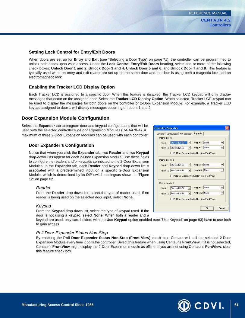
61Manufacturing Access Control Since 1985
CENTAUR 4.2Controllers
REFERENCE MANUAL
Setting Lock Control for Entry/Exit DoorsWhen doors are set up for Entry and Exit (see “Selecting a Door Type” on page 71), the controller can be programmed tounlock both doors upon valid access. Under the Lock Control Entry/Exit Doors heading, select one or more of the followingcheck boxes: Unlock Door 1 and 2, Unlock Door 3 and 4, Unlock Door 5 and 6, and Unlock Door 7 and 8. This feature istypically used when an entry and exit reader are set up on the same door and the door is using both a magnetic lock and anelectromagnetic lock.
Enabling the Tracker LCD Display OptionEach Tracker LCD is assigned to a specific door. When this feature is disabled, the Tracker LCD keypad will only displaymessages that occur on the assigned door. Select the Tracker LCD Display Option. When selected, Tracker LCD keypad canbe used to display the messages for both doors on the controller or 2-Door Expansion Module. For example, a Tracker LCDkeypad assigned to door 1 will display messages occurring on doors 1 and 2.
Door Expansion Module ConfigurationSelect the Expander tab to program door and keypad configurations that will be used with the selected controller’s 2-Door Expansion Modules (CA-A470-A). A maximum of three 2-Door Expansion Modules can be used with each controller.
Door Expander’s ConfigurationNotice that when you click the Expander tab, two Reader and two Keypaddrop-down lists appear for each 2-Door Expansion Module. Use these fieldsto configure the readers and/or keypads connected to the 2-Door ExpansionModules. In the Expander tab, each Reader and Keypad drop-down list isassociated with a predetermined input on a specific 2-Door ExpansionModule, which is determined by its DIP switch settingsas shown in “Figure12” on page 62.
ReaderFrom the Reader drop-down list, select the type of reader used. If noreader is being used on the selected door input, select None.
KeypadFrom the Keypad drop-down list, select the type of keypad used. If thedoor is not using a keypad, select None. When both a reader and akeypad are used, only card holders with the Use Keypad option enabled (see “Use Keypad” on page 93) have to use bothto gain access.
Poll Door Expander Status Non-StopBy enabling the Poll Door Expander Status Non-Stop (Front View) check box, Centaur will poll the selected 2-DoorExpansion Module every time it polls the controller. Select this feature when using Centaur’s FrontView. If it is not selected,Centaur’s FrontView might display the 2-Door Expansion module as offline. If you are not using Centaur’s FontView, clearthis feature check box.
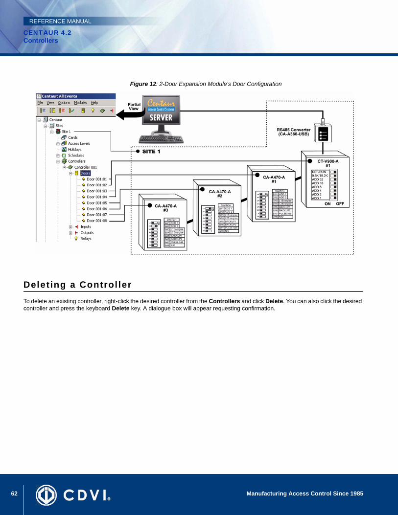
62 Manufacturing Access Control Since 1985
CENTAUR 4.2Controllers
REFERENCE MANUAL
Figure 12: 2-Door Expansion Module’s Door Configuration
Deleting a ControllerTo delete an existing controller, right-click the desired controller from the Controllers and click Delete. You can also click the desired controller and press the keyboard Delete key. A dialogue box will appear requesting confirmation.
63Manufacturing Access Control Since 1985
CENTAUR 4.2Controllers
REFERENCE MANUAL
Online Controller Firmware UpgradesWith the Centaur software there’s no need to change the microchips of each controller. Centaur can download the new firmware to some or all of the controllers in your installation in just a few easy steps.
The latest version of the controller firmware can be downloaded from our website at www.cdvi.ca. Please note that the controller firmware consists of two files, one with a HXL extension and the other with a HXH extension. Also, the file name will indicate the version and release number of the firmware. Use the View Controller Status command (see page 65) to verify the application version currently used by the controller.
Updating Controller FirmwareOnce the firmware files have been downloaded from our website, the controller(s) can be updated within Centaur. Perform the following to update the controller’s firmware:
1. Ensure that you are connected (communicating) with the controllers in Centaur. The Centaur software must be running.
2. Within Centaur, expand the desired Site in the Database Tree View window and expand the Controllers folder.
3. From the expanded Controllers folder, right-click on a controller whose firmware you would like to update and click Update Firmware.
4. Under the Firmware Files heading, browse and select the required HXH file.
5. Click Update.
When updating the controllers, the controllers cannot control access or perform any other monitoring functions. Therefore, we recommend that firmware updates are performed when traffic is at a minimum and advise users of any interruptions that may occur.
Each site must be updated separately. We recommend one controller at a time.

64 Manufacturing Access Control Since 1985
CENTAUR 4.2Controllers
REFERENCE MANUAL
DownloadThe Centaur software can download the following system characteristics to one or all controllers in a site: access levels, cards, controllers, doors, holidays, inputs, input groups, outputs, output timings, relays, relay groups, and schedules. If any system characteristics are set when a controller is online, Centaur will automatically download the information to all controllers in the site.
When to Use the Download Function• When you update the controller firmware (see “Online Controller Firmware Upgrades” on page 63), the controller memory will
be erased. You must download the Centaur database to the controllers.
• If you wish to program any items without connecting to the site, you must download the system characteristics to the controllers the next time you connect.
• If you wish to download a particular characteristic to a specific controller in a site, program the desired characteristic without connecting, then connect and download to the desired controller.
Downloading to One Controllers
1. To download to one controller in a site, from the desired Site, right-click a controller from the Controllers.
2. From the drop-down list, select Download.
3. Click All or only the specific programming item you wish to download (i.e. doors). Please note that download time depends on the size of the database. Downloading 20 cards will take less time than 3,500 cards.

65Manufacturing Access Control Since 1985
CENTAUR 4.2Controllers
REFERENCE MANUAL
Other Controller Management OptionsThe following controller management options are also available when you right-click a controller within the Controllers of a desired site.
Updating the Controller TimeThe Centaur software can update the date and time of one controller or all controllers in a site. To do so, right-click a controller from the Controllers of the desired site, and click Update Time. In the Date/Time window, type the required date and time. If you wish to update all controllers in the selected site, select the Update all controllers on this site check box. Click OK. Also, refer to “Updating the Controller Time Automatically” on page 32.
Viewing Controller StatusThe View Controller Status command allows you to view the complete details of each controller. The Centaur software will display the selected controller’s site, address, status, firmware version, number of cards and errors that may have occurred and the controller’s voltage status. To view the controller status, right-click the desired controller from the Controllers and click View Controller Status.
Resetting the ControllerTo perform a controller reset, right-click a controller from the desired site’s Controllers and click Reset Controller. This will not affect any items you may have already programmed, such as cards, doors, inputs, etc.
Activating/Deactivating the ControllerTo activate a controller, right-click a controller from the desired site’s Controllers and click Activate Controller. To deactivate a controller, right-click a controller from the desired site’s Controllers and click Deactivate Controller.
If the DIP switch on the controller is set to “default”, performing a controller reset will reset all programming such as cards, doors, and inputs to default.

66 Manufacturing Access Control Since 1985
CENTAUR 4.2Controllers
REFERENCE MANUAL
67
CENTAUR 4.2Access Control Software
Manufacturing Access Control Since 1985
REFERENCE MANUAL
Chapter 7: Doors
What Will I Find?Adding Doors . . . . . . . . . . . . . . . . . . . . . . . . . . . . . . . . . . . . . . . . . . . . . . . . . . . . . . . . . . . . . . . . . . . . . . . . . . . . . . . . . . . . . . . . . . . 68 Modifying a Door . . . . . . . . . . . . . . . . . . . . . . . . . . . . . . . . . . . . . . . . . . . . . . . . . . . . . . . . . . . . . . . . . . . . . . . . . . . . . . . . . . . . . . . . 69 Deleting a Door . . . . . . . . . . . . . . . . . . . . . . . . . . . . . . . . . . . . . . . . . . . . . . . . . . . . . . . . . . . . . . . . . . . . . . . . . . . . . . . . . . . . . . . . . 80 Display Door Status . . . . . . . . . . . . . . . . . . . . . . . . . . . . . . . . . . . . . . . . . . . . . . . . . . . . . . . . . . . . . . . . . . . . . . . . . . . . . . . . . . . . . . 81
Each controller includes 2 reader and 2 keypad inputs, which can monitor the state of up to 2 doors. Each controller also supports up to three 2-Door Expansion Modules (CA-A470-A), which provide an additional 2 reader and 2 keypad inputs each. Therefore, each controller can monitor the state of up to 8 doors.
The term door refers to any access point controlled by a reader and/or keypad such as a door, turnstile, gate, cabinet, etc. To control entry and exit to an access point, a reader and/or keypad can be used on both sides of the door. This also provides the ability to set up Interlock (“mantrap”) or Anti-passback applications.
The use of door contacts on all controlled doors is highly recommended since it greatly enhances the level of security provided by an access control system. Many of the door’s programmable options can only be used if a door contact is installed.
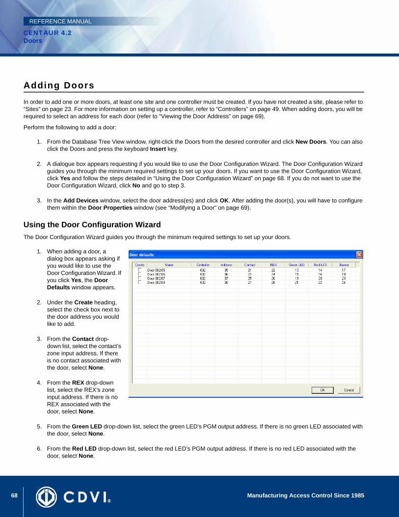
68 Manufacturing Access Control Since 1985
CENTAUR 4.2Doors
REFERENCE MANUAL
Adding DoorsIn order to add one or more doors, at least one site and one controller must be created. If you have not created a site, please refer to “Sites” on page 23. For more information on setting up a controller, refer to “Controllers” on page 49. When adding doors, you will be required to select an address for each door (refer to “Viewing the Door Address” on page 69).
Perform the following to add a door:
1. From the Database Tree View window, right-click the Doors from the desired controller and click New Doors. You can also click the Doors and press the keyboard Insert key.
2. A dialogue box appears requesting if you would like to use the Door Configuration Wizard. The Door Configuration Wizard guides you through the minimum required settings to set up your doors. If you want to use the Door Configuration Wizard, click Yes and follow the steps detailed in “Using the Door Configuration Wizard” on page 68. If you do not want to use the Door Configuration Wizard, click No and go to step 3.
3. In the Add Devices window, select the door address(es) and click OK. After adding the door(s), you will have to configure them within the Door Properties window (see “Modifying a Door” on page 69).
Using the Door Configuration WizardThe Door Configuration Wizard guides you through the minimum required settings to set up your doors.
1. When adding a door, a dialog box appears asking if you would like to use the Door Configuration Wizard. If you click Yes, the Door Defaults window appears.
2. Under the Create heading, select the check box next to the door address you would like to add.
3. From the Contact drop-down list, select the contact’s zone input address. If there is no contact associated with the door, select None.
4. From the REX drop-down list, select the REX’s zone input address. If there is no REX associated with the door, select None.
5. From the Green LED drop-down list, select the green LED’s PGM output address. If there is no green LED associated with the door, select None.
6. From the Red LED drop-down list, select the red LED’s PGM output address. If there is no red LED associated with the door, select None.
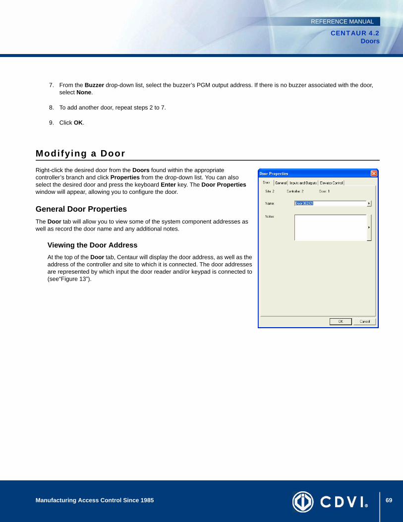
69Manufacturing Access Control Since 1985
CENTAUR 4.2Doors
REFERENCE MANUAL
7. From the Buzzer drop-down list, select the buzzer’s PGM output address. If there is no buzzer associated with the door, select None.
8. To add another door, repeat steps 2 to 7.
9. Click OK.
Modifying a DoorRight-click the desired door from the Doors found within the appropriate controller’s branch and click Properties from the drop-down list. You can also select the desired door and press the keyboard Enter key. The Door Properties window will appear, allowing you to configure the door.
General Door PropertiesThe Door tab will allow you to view some of the system component addresses as well as record the door name and any additional notes.
Viewing the Door AddressAt the top of the Door tab, Centaur will display the door address, as well as theaddress of the controller and site to which it is connected. The door addressesare represented by which input the door reader and/or keypad is connected to(see“Figure 13”).
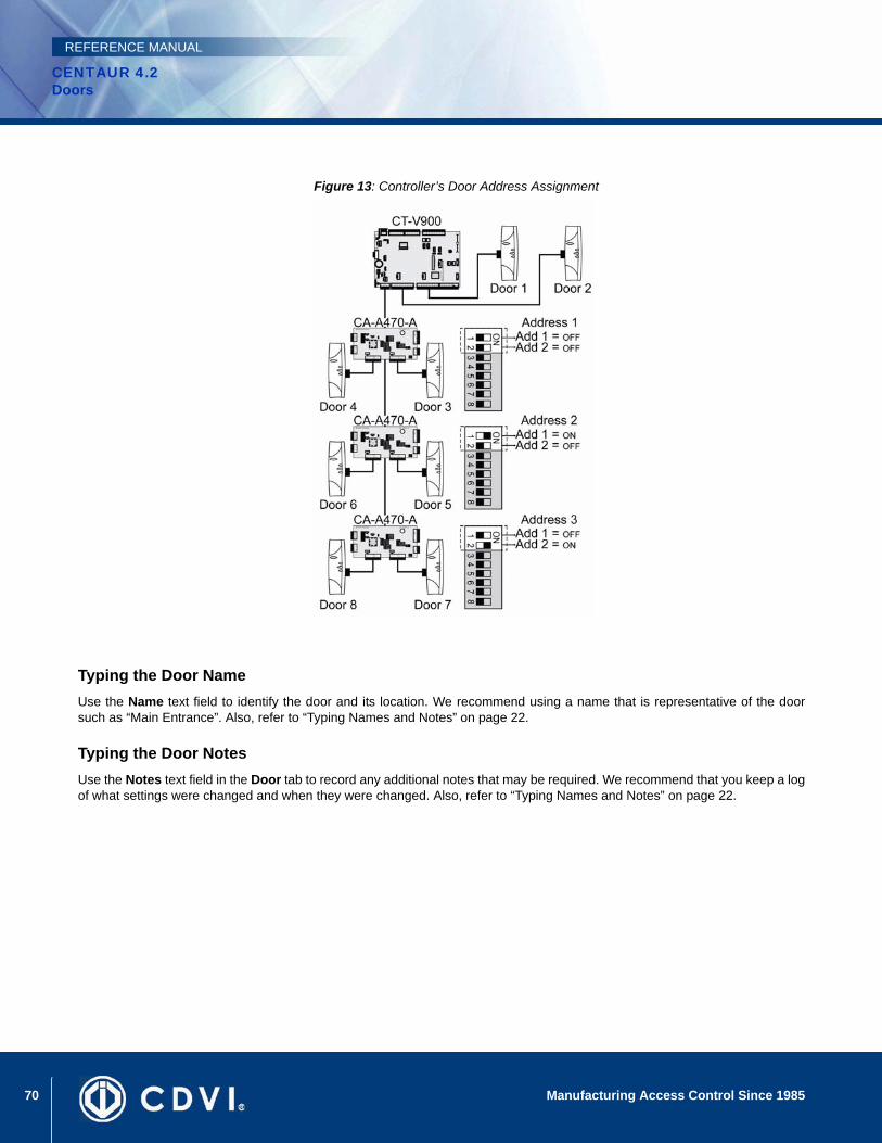
70 Manufacturing Access Control Since 1985
CENTAUR 4.2Doors
REFERENCE MANUAL
Figure 13: Controller’s Door Address Assignment
Typing the Door NameUse the Name text field to identify the door and its location. We recommend using a name that is representative of the doorsuch as “Main Entrance”. Also, refer to “Typing Names and Notes” on page 22.
Typing the Door NotesUse the Notes text field in the Door tab to record any additional notes that may be required. We recommend that you keep a logof what settings were changed and when they were changed. Also, refer to “Typing Names and Notes” on page 22.

71Manufacturing Access Control Since 1985
CENTAUR 4.2Doors
REFERENCE MANUAL
Door SettingsEach controller includes 2 reader and 2 keypad inputs, which can monitor the state of up to 2 doors. Each controller also supports up to three 2-Door Expansion Modules (CA-A470-A), which provide an additional 2 reader and 2 keypad inputs each. Therefore, each controller can monitor the state of up to 8 doors.
The term “door” refers to any access point controlled by a reader and/or keypad such as a door, turnstile, gate, cabinet, etc. To control entry and exit to an access point a reader and/or keypad can be used on both sides of the door. This also provides the ability to set up Interlock (“mantrap”) or Anti-passback applications. Centaur enables you to define a specific configuration for each door as well as set the door’s various timers.
Selecting a Door TypeDepending on the hardware configuration being used for the selected door,you must select the appropriate door type for the selected door. From theDoor Properties window, select the General tab. From the Door Type drop-down list, select the required door type:
AccessSelect the Access door type if you plan to use the controlled entry (one reader access) configuration. This means the reader will be located on one side of a door with no reader on the other side.
ElevatorWhen using CA-A480 Elevator Controllers (refer to “Elevator Control” on page 105), a reader can be installed inside an elevator. When you select Elevator from the Door Type drop-down list, Centaur tells the controller that the selected door reader will be installed inside an elevator cart for elevator control. The door cannot be used for any other purpose. Also note that options and features located in the Elevator Control tab can only be set when the Door Type is set to Elevator (see “Floor Public Access Schedule” on page 79). Each controller door can control up to 64 floors for one elevator cart. Please note that the number of floors is defined per site and not per door (see “Site Floor Settings” on page 35). For example, if you define a site with 20 floors and set up four doors from the same site for elevator control, each door will represent a different elevator cart for the same 20 floors.
Entry or ExitSelect the Entry door type for the reader located on the entry side of the door and select the Exit door type for the exit readerlocated on the other side of the door. This configuration must be used to implement the local Anti-passback feature (see“Enabling Controller Anti-passback” on page 60).
Global Entry or Global ExitThese door types allow you to use global anti-passback, which functions independently and provides more versatility thanthe local anti-passback feature (see “Enabling Controller Anti-passback” on page 60).
When using Entry and Exit door types (see above), card holders must enter and exit through a door on the same controller.
The Elevator door type cannot be selected for doors located on a 2-Door Expansion Module (doors 3 to 8). Only the controller doors can be set with the Elevator door type.

72 Manufacturing Access Control Since 1985
CENTAUR 4.2Doors
REFERENCE MANUAL
When using the Global Entry and Global Exit door types, a card holder can enter through a door defined as global entry, andthen the card holder can exit through any door defined as global exit.
You can also reset the global anti-passback status of all card holders. For more information, refer to “Selecting a Site’sGlobal Anti-Passback Reset Schedule” on page 34.
Example: As demonstrated in “Figure 14”, if a card holder were to enter through door 1 (Global Entry), the card holder would be able to exit through either door 1 (Global Exit) or door 2 (Global Exit), but not through door 3 since it is not defined as a Global Exit (meaning that the card holder would still be considered as in).
Figure 14: Global Entry/Exit
Two Card RuleSelect the Two Card Rule door type when two card holder credentials are mandatory to access the door. This means thatthe two card holders will have to present their cards one after the other within the defined delay as defined in the “Two cardrule delay” on page 75.
Selecting the Reading DevicesFrom the Reading device drop-down list, select the device that will be used to obtain access to the door, either a keypad, or areader.
ReaderIf you are connecting a reader, or a reader and a keypad, select Reader from the drop-down list. The controller will recognizethe use of a keypad if a keypad has been set up in the controller door configuration (see “Selecting the Door Reader andKeypad Configuration” on page 55).
KeypadIf you are connecting only a keypad (no reader) to the door input, select Keypad from the drop-down list.
Global Entry and Exit will only function when the Centaur Server is online (connected). Please note that when using Global Entry and Exit, the Centaur system will also generate a “Waiting for Host” event with every “Access Granted” event generated from a door defined with Global Entry or Exit.
73Manufacturing Access Control Since 1985
CENTAUR 4.2Doors
REFERENCE MANUAL
Selecting the Lock Control TypeFrom the Lock Control drop-down list, select the activation (locking) method that will be used by the door when an “AccessGranted” or “Unlock” event occurs.
De-energizeTo operate in fail-secure mode (apply power to unlock a door), select De-energize from the Lock Control drop-down list.This means the selected lock output on the controller will remain de-activated. When an Access Granted or Door Unlockedevent occurs, the controller will apply power to the lock output. If an electric door strike is used, this mode will keep the doorlocked during a total power loss.
EnergizeTo operate in fail-safe mode (remove power to unlock a door), select Energize from the Lock Control drop-down list. Thismeans the lock output on the controller will remain activated. When an Access Granted or Door Unlocked event occurs,the controller will remove power from the lock output. If an electric door strike or an electromagnetic lock is used, this modewill unlock the door during a total power loss.
Selecting a Keypad ScheduleFrom the Keypad Schedule drop-down list, select the schedule that will determine when both a reader and a keypad must beused in order to gain access. When the selected schedule is valid, the card holder must present a valid card to the reader, andthen a valid P.I.N. must be entered on the keypad before access is granted. Only cards with the Use Keypad option enabledmust enter a valid keypad P.I.N. (see “Use Keypad” on page 93). For more information on schedules, refer to “Schedules” onpage 43.
Selecting the Door Unlock Schedule From the Unlock Schedule drop-down list, select the schedule during which a controlled door will automatically unlock. Forexample, you may want a door to remain open (unlocked) from 9 a.m. to 5 p.m. Monday to Friday. To do so, create theappropriate schedule and select it from the Unlock Schedule drop-down list. For more information on schedules, refer to“Schedules” on page 43. Also, refer to “Unlock on Late Open” on page 73.
Setting the Reading Type OptionsUnder the Reading Type heading, select one or more of the following check boxes. These check boxes determine how andwhen a controller will read (log) the presentation of a card to the door’s reader.
OpenedWhen the Opened check box is selected, the controller will continue to read cards presented to the door reader when thedoor is already opened. This option is commonly used in conjunction with the “Controller Anti-passback Settings” (seepage 60) in high-traffic areas. This prevents Anti-passback errors from occurring due to users forgetting to wait until the dooris closed before presenting their card.
UnlockedWhen the Unlocked check box is selected, the controller will continue to read cards presented to the door’s reader whenthe door is already unlocked. This option is commonly used in conjunction with the “Controller Anti-passback Settings” (seepage 60) when the door may be unlocked by a schedule. This prevents Anti-passback errors from occurring due to a userpresenting a card to a reader of a door that has already been unlocked by a schedule.
Unlock on Late OpenWhen “Selecting the Door Unlock Schedule” (see page 73), select Unlock on Late Open to prevent the door from unlockingautomatically until the first person with valid access presents their card at the door.

74 Manufacturing Access Control Since 1985
CENTAUR 4.2Doors
REFERENCE MANUAL
Example: The feature is enabled and the front door of an establishment has been programmed to unlock (via schedule)between 8AM and 5PM. If by 8:15 no one has presented their card to the front door’s reader, it will not unlock. When the firstperson arrives at 8:30AM and presents a valid card, the door will remain unlocked until 5PM.
Time and AttendanceWhen the Time and Attendance check box is selected, the time and attendance from the punch device become availablefor the ProReport module.
Setting the Door TimersUnder the Timings heading, you can set four different door timers as detailed below.
Unlock Time In the Unlock time text field enter a value between 001 and 999 seconds (Default: 5 seconds). This value represents theamount of time the door will remain unlocked when an “Access Granted” or “Unlock” event is generated from the door. Thedoor will only remain unlocked for the entire Unlock Time if the Door Input Relock schedule and REX Input Relock scheduleare disabled or if no door input has been programmed. For more information, refer to “Door Inputs and Outputs” on page 76.
Pre-alarm TimeBefore generating an Open Too Long event (see “Open Too Long” on page 74), the controller can be programmed togenerate a pre-alarm as a warning of the upcoming alarm. In the Pre-alarm time text field, type a value between 001 and999 seconds (Default: 45 seconds). This value represents the amount of time a door can remain open after an AccessGranted or Door Unlock event before generating a Door Left Open event. The Pre-alarm time should always be less thanthe Open too long time (see “Figure 15”). The controller can also be programmed to activate an output when a Door LeftOpen event is generated (see “Outputs” on page 125).
Open Too LongIn the Open too long text field, enter a value between 1 and 999 seconds (Default: 60 seconds). This value represents theamount of time a door can remain open after an Access Granted or Door Unlock event before generating a Door OpenToo Long event (see“Figure 15”). The controller can also be programmed to activate an output when a Door Open TooLong event is generated (see “Outputs” on page 125). Also, refer to “Pre-alarm Time” on page 74.
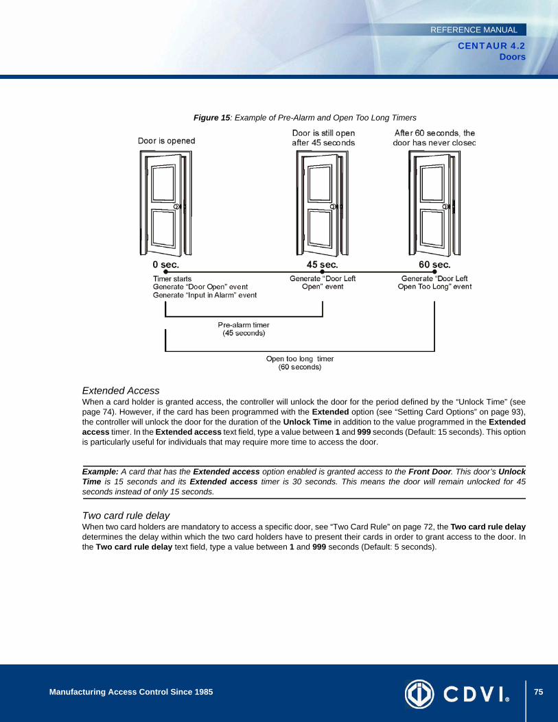
75Manufacturing Access Control Since 1985
CENTAUR 4.2Doors
REFERENCE MANUAL
Figure 15: Example of Pre-Alarm and Open Too Long Timers
Extended AccessWhen a card holder is granted access, the controller will unlock the door for the period defined by the “Unlock Time” (seepage 74). However, if the card has been programmed with the Extended option (see “Setting Card Options” on page 93),the controller will unlock the door for the duration of the Unlock Time in addition to the value programmed in the Extendedaccess timer. In the Extended access text field, type a value between 1 and 999 seconds (Default: 15 seconds). This optionis particularly useful for individuals that may require more time to access the door.
Example: A card that has the Extended access option enabled is granted access to the Front Door. This door’s UnlockTime is 15 seconds and its Extended access timer is 30 seconds. This means the door will remain unlocked for 45seconds instead of only 15 seconds.
Two card rule delayWhen two card holders are mandatory to access a specific door, see “Two Card Rule” on page 72, the Two card rule delaydetermines the delay within which the two card holders have to present their cards in order to grant access to the door. Inthe Two card rule delay text field, type a value between 1 and 999 seconds (Default: 5 seconds).

76 Manufacturing Access Control Since 1985
CENTAUR 4.2Doors
REFERENCE MANUAL
Door Inputs and OutputsThe Inputs and Outputs tab will allow you to specify the configuration for the door input, REX input and its interlock (mantrap) input as well as select which output(s) can be activated for the selected door.
Assigning a Door InputAfter installing a door contact, use the Door Input settings to enable thecontroller to supervise the status of a door (open/closed). A door input is used:
• To generate Door Open and Door Forced events
• To generate Open Too Long and Door Left Open events (see “Setting the Door Timers” on page 74)
• To effectively use the Anti-passback feature (see “Controller Anti-passback Settings” on page 60)
• For Interlock (“mantrap”) applications (see “Assigning an Interlock Input” on page 77)
Perform the following to set up a door input:
1. A door contact must be installed above the door and it must be connected to an input on the controller (see the appropriate controller’s Installation Manual).
2. The input must be programmed as detailed in “Inputs” on page 115.
3. Under the Door Input heading, select the desired input from the Input drop-down list.
4. Select a relock option from the Relock drop-down list under the Door Input heading. After a valid access through the use of a card, the control panel can relock the door as soon as it opens (Door opening), when the door closes (Door closing), or if you select Disabled, it will relock when the Unlock Time has elapsed (see “Unlock Time” on page 74). Also, refer to “Selecting the Lock Control Type” on page 73.
Assigning a REX Input (Request for Exit) A request for exit (REX) input is required if you have selected the Access (controlled entry) configuration (see “Selecting a DoorType” on page 71). If you do not use a REX input, the controller will not be able to distinguish between a valid exit and a forcedexit. The controller will always generate a “Door Forced” event. Perform the following to set up a REX input:
1. A vertical motion detector must be installed above the door and it must be connected to an input on the controller (refer to the appropriate controller’s Installation Manual).
2. The input must be programmed as detailed in “Inputs” on page 115.
3. Under the REX Input heading, select the desired input from the Input drop-down list.
4. From the Schedule drop-down list under the REX Input heading, select the schedule which will define when the REX can be used.
77Manufacturing Access Control Since 1985
CENTAUR 4.2Doors
REFERENCE MANUAL
5. Select a relock option from the Relock drop-down list under the REX Input heading. After a valid Request for Exit access, the control panel can relock the door as soon as it opens (Door opening), when the door closes (Door closing), or if you select Disabled, it will relock when the Unlock Time has elapsed (see “Unlock Time” on page 74). Also, refer to “Selecting the Lock Control Type” on page 73.
6. Select the Unlock on REX (Normal) check box if you wish the controller to unlock the door when the controller receives a valid Request for Exit (the door must be closed and locked). To unlock the door regardless of its current status (i.e. Door forced, Door open too long, etc.), select the Unlock on Rex (Regardless of Door Status) check box.
Assigning an Interlock InputThis feature allows you to set up the doors for use with Interlock (Mantrap) applications. A “mantrap” consists of two doors,each controlled by a card reader and/or keypad. When one of the two doors is open or unlock, it is impossible to open the otherdoor until both doors are closed. Please note that the selected doors must be from the same controller.
An interlock input is required if the door will be used in a “mantrap” configuration or to generate Access Denied - InterlockActive and Interlock Enabled/Disabled by Schedule events
Perform these steps for each of the two doors being used in the mantrap configuration.
1. Make sure the door inputs have been programmed (see “Assigning a Door Input” on page 76).
2. From the Input drop-down list under the Interlock Input heading, select the same input that is assigned to the door input of the other door in the mantrap configuration.
3. From the Schedule drop-down list under the Interlock Input heading, select the schedule which will define when the Interlock (mantrap) configuration can be used.
The Interlock Inputs feature cannot be used with doors located on a 2-Door Expansion Module (doors 3 to 8). Only the controller’s doors can use Interlock Inputs.
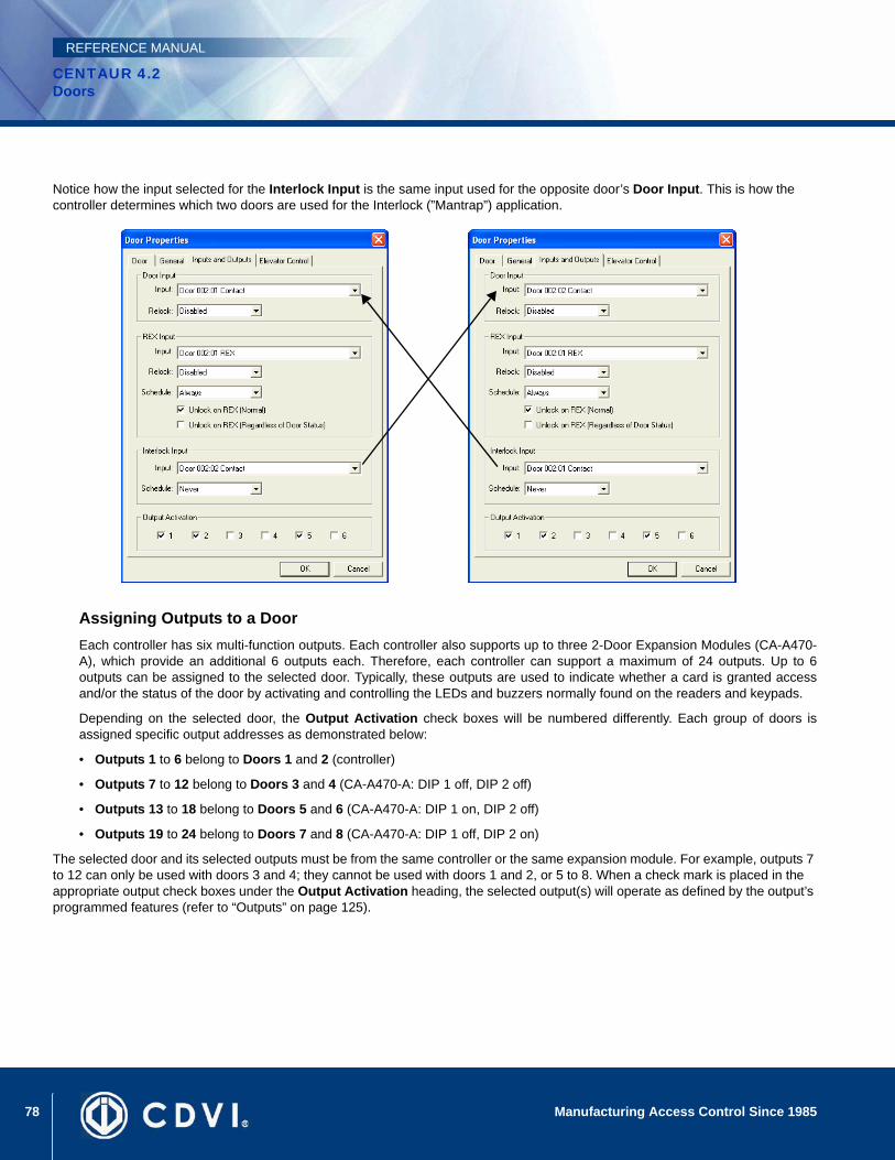
78 Manufacturing Access Control Since 1985
CENTAUR 4.2Doors
REFERENCE MANUAL
Notice how the input selected for the Interlock Input is the same input used for the opposite door’s Door Input. This is how the controller determines which two doors are used for the Interlock (”Mantrap”) application.
Assigning Outputs to a DoorEach controller has six multi-function outputs. Each controller also supports up to three 2-Door Expansion Modules (CA-A470-A), which provide an additional 6 outputs each. Therefore, each controller can support a maximum of 24 outputs. Up to 6outputs can be assigned to the selected door. Typically, these outputs are used to indicate whether a card is granted accessand/or the status of the door by activating and controlling the LEDs and buzzers normally found on the readers and keypads.
Depending on the selected door, the Output Activation check boxes will be numbered differently. Each group of doors isassigned specific output addresses as demonstrated below:
• Outputs 1 to 6 belong to Doors 1 and 2 (controller)
• Outputs 7 to 12 belong to Doors 3 and 4 (CA-A470-A: DIP 1 off, DIP 2 off)
• Outputs 13 to 18 belong to Doors 5 and 6 (CA-A470-A: DIP 1 on, DIP 2 off)
• Outputs 19 to 24 belong to Doors 7 and 8 (CA-A470-A: DIP 1 off, DIP 2 on)
The selected door and its selected outputs must be from the same controller or the same expansion module. For example, outputs 7 to 12 can only be used with doors 3 and 4; they cannot be used with doors 1 and 2, or 5 to 8. When a check mark is placed in the appropriate output check boxes under the Output Activation heading, the selected output(s) will operate as defined by the output’s programmed features (refer to “Outputs” on page 125).

79Manufacturing Access Control Since 1985
CENTAUR 4.2Doors
REFERENCE MANUAL
Floor Public Access Schedule When using CA-A480 Elevator Controllers (refer to “Elevator Control” on page 105), a reader can be installed inside an elevator. Each controller’s door (elevator cart) can be programmed with a general/public access schedule by assigning a schedule to each of the door’s assigned floors. This defines, for the selected door, which floors are accessible to the general public (no access card required) and during which time period. Please note that to program these schedules, the door type must be set to Elevator (see “Door Settings” on page 71).
Setting Up a Door Public Access SchedulePerform the following to assign one or more floors to a door and to assign aschedule to each floor:
1. To assign a floor to the door, select the check box associated with the desired floor. The Schedule drop-down list will become active.
2. From the Schedule drop-down list, select the schedule you would like to assign to the selected floor. Although there is only one Schedule drop-down list, you can assign a different schedule to each selected floor. The selected schedule will be assigned to the highlighted floor whose check box is selected.
3. Return to step 2 to assign another floor and schedule, or click OK to save and exit.
The Elevator Floor Schedule cannot be used with doors located on a 2-Door Expansion Module (doors 3 to 8). Only the controller’s doors can be set for elevator control.
Example: In “Figure 16”, the “Parking Level 2” floor is enabled and has been assigned the “Weekly (General)” schedule. This means that access to that floor is unrestricted when the “Weekly (General)” schedule is valid. Any user, even those without access cards, can access the “Parking Level 2” floor.
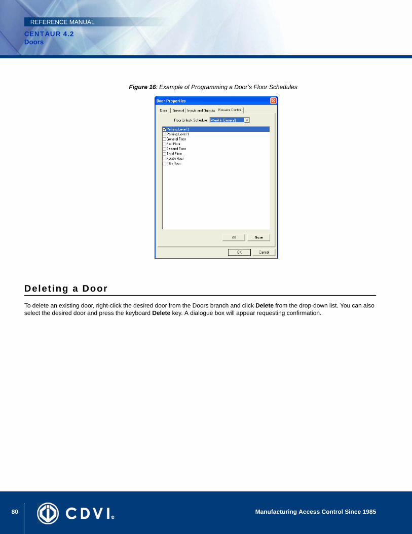
80 Manufacturing Access Control Since 1985
CENTAUR 4.2Doors
REFERENCE MANUAL
Figure 16: Example of Programming a Door’s Floor Schedules
Deleting a DoorTo delete an existing door, right-click the desired door from the Doors branch and click Delete from the drop-down list. You can also select the desired door and press the keyboard Delete key. A dialogue box will appear requesting confirmation.
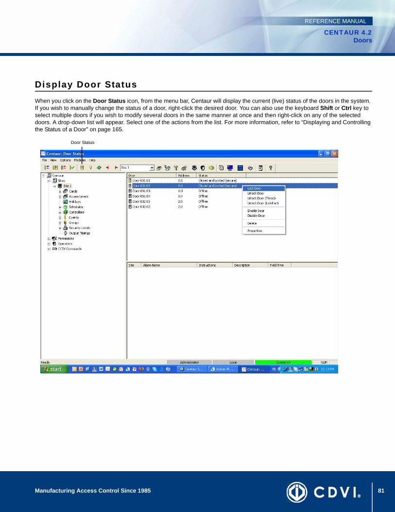
81Manufacturing Access Control Since 1985
CENTAUR 4.2Doors
REFERENCE MANUAL
Display Door StatusWhen you click on the Door Status icon, from the menu bar, Centaur will display the current (live) status of the doors in the system. If you wish to manually change the status of a door, right-click the desired door. You can also use the keyboard Shift or Ctrl key to select multiple doors if you wish to modify several doors in the same manner at once and then right-click on any of the selected doors. A drop-down list will appear. Select one of the actions from the list. For more information, refer to “Displaying and Controlling the Status of a Door” on page 165.
Door Status

82 Manufacturing Access Control Since 1985
CENTAUR 4.2Doors
REFERENCE MANUAL
83
CENTAUR 4.2Access Control Software
Manufacturing Access Control Since 1985
REFERENCE MANUAL
Chapter 8: Access Levels
What Will I Find?Adding an Access Level . . . . . . . . . . . . . . . . . . . . . . . . . . . . . . . . . . . . . . . . . . . . . . . . . . . . . . . . . . . . . . . . . . . . . . . . . . . . . . . . . . 84 Modifying an Access Level . . . . . . . . . . . . . . . . . . . . . . . . . . . . . . . . . . . . . . . . . . . . . . . . . . . . . . . . . . . . . . . . . . . . . . . . . . . . . . . . 84Deleting an Access Level. . . . . . . . . . . . . . . . . . . . . . . . . . . . . . . . . . . . . . . . . . . . . . . . . . . . . . . . . . . . . . . . . . . . . . . . . . . . . . . . . . 86
Access levels determine which doors in the system a card holder will have access to and during which periods. This is done by enabling the desired doors in an access level, then assigning a schedule to each selected door and assigning the access level to the desired cards. Please note that the 256 access levels include two default access levels (All and None) which cannot be modified or deleted. The All access level provides access to any door that exists in the site, 24 hours a day including any programmed holidays. The None access level will deny all access at all times. For information on how the access levels are used, refer to “Cards” on page 87.
In order to program the access levels, you must first program the “Sites” on page 23, the “Doors” on page 67 and “Schedules” on page 43.
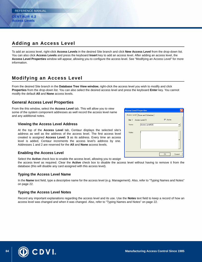
84 Manufacturing Access Control Since 1985
CENTAUR 4.2Access Levels
REFERENCE MANUAL
Adding an Access LevelTo add an access level, right-click Access Levels in the desired Site branch and click New Access Level from the drop-down list. You can also click Access Levels and press the keyboard Insert key to add an access level. After adding an access level, the Access Level Properties window will appear, allowing you to configure the access level. See “Modifying an Access Level” for more information.
Modifying an Access LevelFrom the desired Site branch in the Database Tree View window, right-click the access level you wish to modify and click Properties from the drop-down list. You can also select the desired access level and press the keyboard Enter key. You cannot modify the default All and None access levels.
General Access Level PropertiesFrom the this window, select the Access Level tab. This will allow you to view some of the system component addresses as well record the access level name and any additional notes.
Viewing the Access Level AddressAt the top of the Access Level tab, Centaur displays the selected site’saddress as well as the address of the access level. The first access levelcreated is assigned Access Level: 3 as its address. Every time an accesslevel is added, Centaur increments the access level’s address by one.Addresses 1 and 2 are reserved for the All and None access levels.
Enabling the Access LevelSelect the Active check box to enable the access level, allowing you to assignthe access level as required. Clear the Active check box to disable the access level without having to remove it from thedatabase (this will disable any card assigned with this access level).
Typing the Access Level NameIn the Name text field, type a descriptive name for the access level (e.g. Management). Also, refer to “Typing Names and Notes”on page 22.
Typing the Access Level NotesRecord any important explanations regarding the access level and its use. Use the Notes text field to keep a record of how anaccess level was changed and when it was changed. Also, refer to “Typing Names and Notes” on page 22.
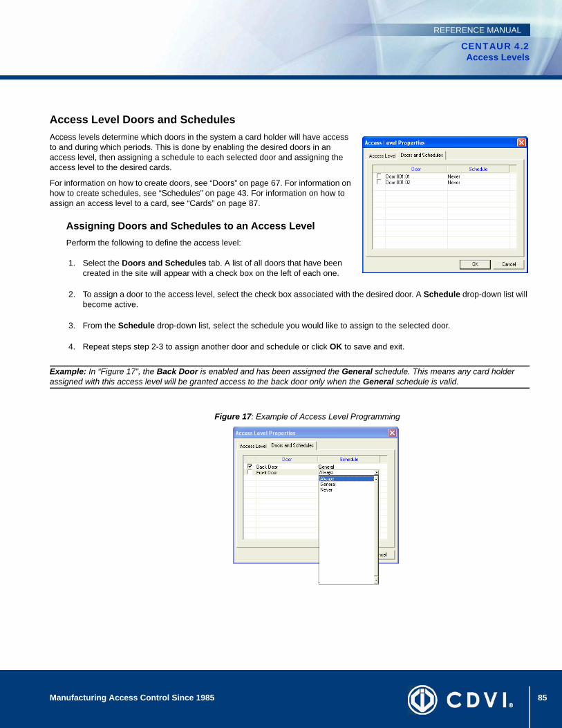
85Manufacturing Access Control Since 1985
CENTAUR 4.2Access Levels
REFERENCE MANUAL
Access Level Doors and SchedulesAccess levels determine which doors in the system a card holder will have access to and during which periods. This is done by enabling the desired doors in an access level, then assigning a schedule to each selected door and assigning the access level to the desired cards.
For information on how to create doors, see “Doors” on page 67. For information on how to create schedules, see “Schedules” on page 43. For information on how to assign an access level to a card, see “Cards” on page 87.
Assigning Doors and Schedules to an Access LevelPerform the following to define the access level:
1. Select the Doors and Schedules tab. A list of all doors that have been created in the site will appear with a check box on the left of each one.
2. To assign a door to the access level, select the check box associated with the desired door. A Schedule drop-down list will become active.
3. From the Schedule drop-down list, select the schedule you would like to assign to the selected door.
4. Repeat steps step 2-3 to assign another door and schedule or click OK to save and exit.
Example: In “Figure 17”, the Back Door is enabled and has been assigned the General schedule. This means any card holder assigned with this access level will be granted access to the back door only when the General schedule is valid.
Figure 17: Example of Access Level Programming
86 Manufacturing Access Control Since 1985
CENTAUR 4.2Access Levels
REFERENCE MANUAL
Deleting an Access LevelIn the Database Tree View window (left-hand portion of your screen), right-click the desired access level and click Delete from the drop-down list. You can also select the desired access level and press the keyboard Delete key. A dialogue box will appear requesting confirmation. You cannot delete the default All and None access levels.
87
CENTAUR 4.2Access Control Software
Manufacturing Access Control Since 1985
REFERENCE MANUAL
Chapter 9: Cards
What Will I Find?Adding Cards . . . . . . . . . . . . . . . . . . . . . . . . . . . . . . . . . . . . . . . . . . . . . . . . . . . . . . . . . . . . . . . . . . . . . . . . . . . . . . . . . . . . . . . . . . . 89 Modifying a Card . . . . . . . . . . . . . . . . . . . . . . . . . . . . . . . . . . . . . . . . . . . . . . . . . . . . . . . . . . . . . . . . . . . . . . . . . . . . . . . . . . . . . . . . 91Deleting a Card . . . . . . . . . . . . . . . . . . . . . . . . . . . . . . . . . . . . . . . . . . . . . . . . . . . . . . . . . . . . . . . . . . . . . . . . . . . . . . . . . . . . . . . . . 95Centaur Card Management Feature . . . . . . . . . . . . . . . . . . . . . . . . . . . . . . . . . . . . . . . . . . . . . . . . . . . . . . . . . . . . . . . . . . . . . . . . . 96Centaur Card Import/Export Feature . . . . . . . . . . . . . . . . . . . . . . . . . . . . . . . . . . . . . . . . . . . . . . . . . . . . . . . . . . . . . . . . . . . . . . . . 102
Programming a card allows you to define the card’s specific privileges and any details concerning the card holder. When setting up the card holders in the system, you must define WHO has access to WHERE, and WHEN they have access. In order to program the cards, you must first program the site (see “Sites” on page 23), doors (see “Doors” on page 67), holidays (see “Holidays” on page 39), schedules (see “Schedules” on page 43), and access levels (see “Access Levels” on page 83). Please note that the number of cards your system can support is also limited by your Centaur edition (refer to “Centaur Editions” on page 2).
Example: In “Figure 18”, John Doe will have access to the “Production Entrance” from 8:00AM to 5:00PM, Monday to Friday including New Year’s Day, and 9:00AM to 13:00PM Sunday and Sathurday.
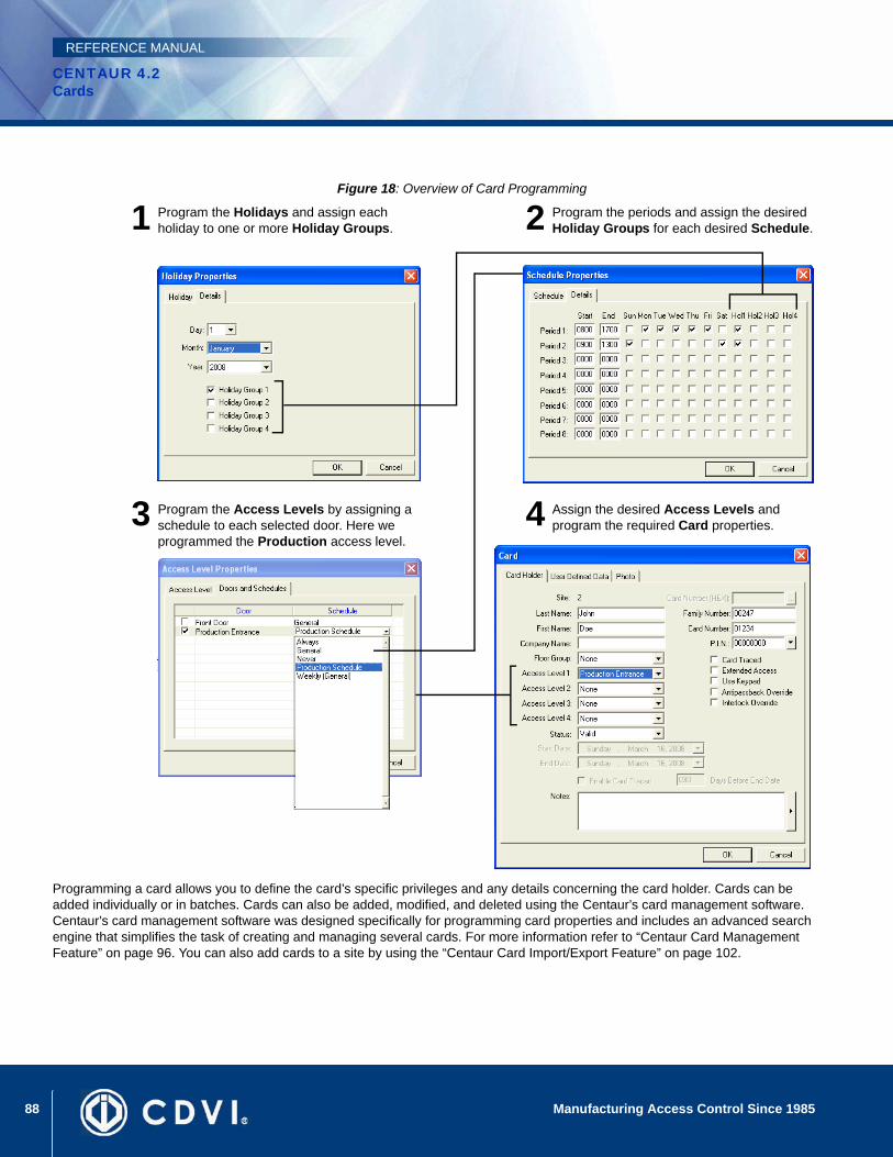
88 Manufacturing Access Control Since 1985
CENTAUR 4.2Cards
REFERENCE MANUAL
Figure 18: Overview of Card Programming
Programming a card allows you to define the card’s specific privileges and any details concerning the card holder. Cards can be added individually or in batches. Cards can also be added, modified, and deleted using the Centaur’s card management software. Centaur’s card management software was designed specifically for programming card properties and includes an advanced search engine that simplifies the task of creating and managing several cards. For more information refer to “Centaur Card Management Feature” on page 96. You can also add cards to a site by using the “Centaur Card Import/Export Feature” on page 102.
Program the Holidays and assign each holiday to one or more Holiday Groups.
Program the periods and assign the desired Holiday Groups for each desired Schedule.
Program the Access Levels by assigning a schedule to each selected door. Here we programmed the Production access level.
Assign the desired Access Levels and program the required Card properties.
1 2
3 4
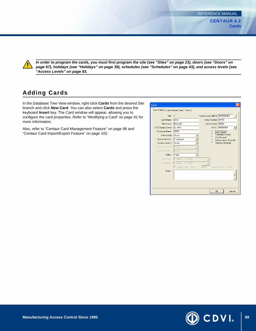
89Manufacturing Access Control Since 1985
CENTAUR 4.2Cards
REFERENCE MANUAL
Adding CardsIn the Database Tree View window, right-click Cards from the desired Site branch and click New Card. You can also select Cards and press the keyboard Insert key. The Card window will appear, allowing you to configure the card properties. Refer to “Modifying a Card” on page 91 for more information.
Also, refer to “Centaur Card Management Feature” on page 96 and “Centaur Card Import/Export Feature” on page 102.
In order to program the cards, you must first program the site (see “Sites” on page 23), doors (see “Doors” on page 67), holidays (see “Holidays” on page 39), schedules (see “Schedules” on page 43), and access levels (see “Access Levels” on page 83.
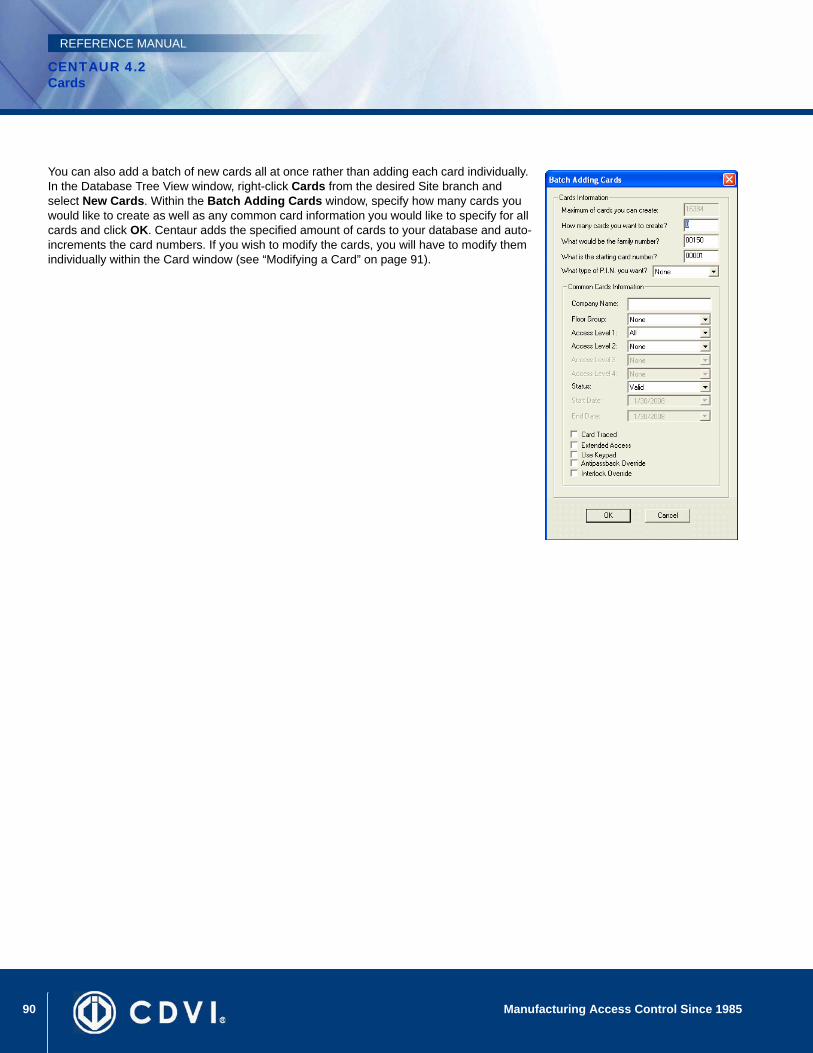
90 Manufacturing Access Control Since 1985
CENTAUR 4.2Cards
REFERENCE MANUAL
You can also add a batch of new cards all at once rather than adding each card individually. In the Database Tree View window, right-click Cards from the desired Site branch and select New Cards. Within the Batch Adding Cards window, specify how many cards you would like to create as well as any common card information you would like to specify for all cards and click OK. Centaur adds the specified amount of cards to your database and auto-increments the card numbers. If you wish to modify the cards, you will have to modify them individually within the Card window (see “Modifying a Card” on page 91).
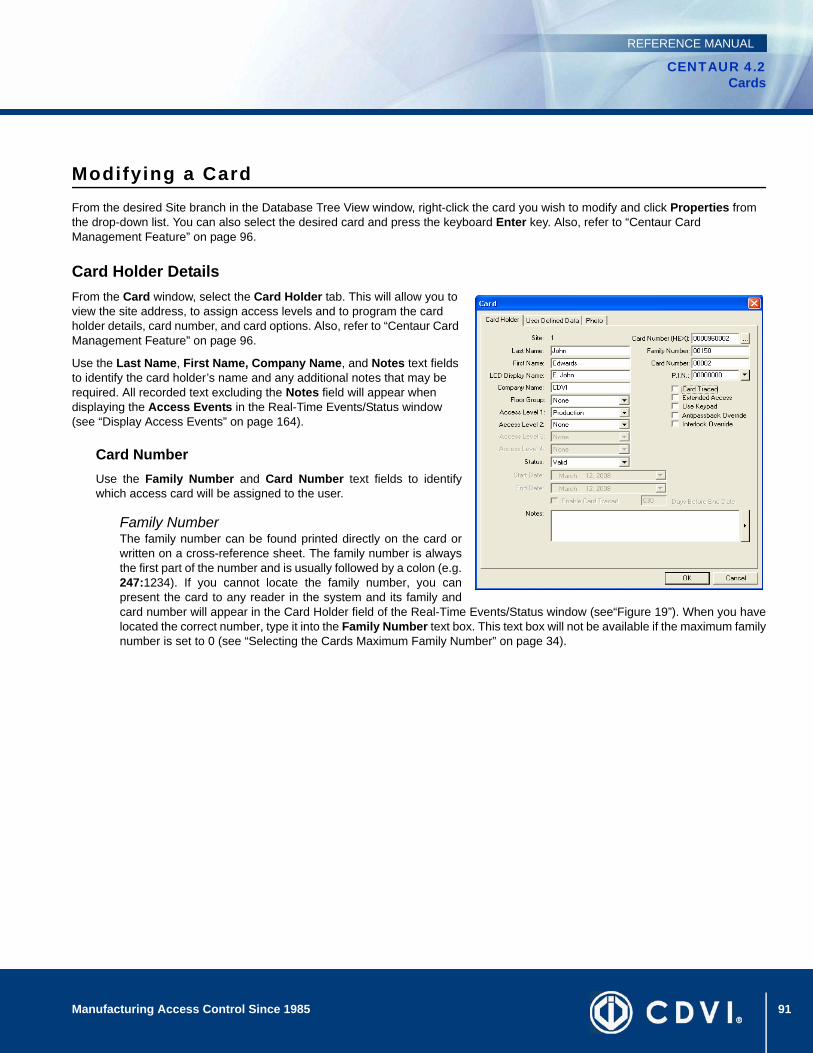
91Manufacturing Access Control Since 1985
CENTAUR 4.2Cards
REFERENCE MANUAL
Modifying a CardFrom the desired Site branch in the Database Tree View window, right-click the card you wish to modify and click Properties from the drop-down list. You can also select the desired card and press the keyboard Enter key. Also, refer to “Centaur Card Management Feature” on page 96.
Card Holder DetailsFrom the Card window, select the Card Holder tab. This will allow you to view the site address, to assign access levels and to program the card holder details, card number, and card options. Also, refer to “Centaur Card Management Feature” on page 96.
Use the Last Name, First Name, Company Name, and Notes text fields to identify the card holder’s name and any additional notes that may be required. All recorded text excluding the Notes field will appear when displaying the Access Events in the Real-Time Events/Status window (see “Display Access Events” on page 164).
Card NumberUse the Family Number and Card Number text fields to identifywhich access card will be assigned to the user.
Family NumberThe family number can be found printed directly on the card orwritten on a cross-reference sheet. The family number is alwaysthe first part of the number and is usually followed by a colon (e.g.247:1234). If you cannot locate the family number, you canpresent the card to any reader in the system and its family andcard number will appear in the Card Holder field of the Real-Time Events/Status window (see“Figure 19”). When you havelocated the correct number, type it into the Family Number text box. This text box will not be available if the maximum familynumber is set to 0 (see “Selecting the Cards Maximum Family Number” on page 34).
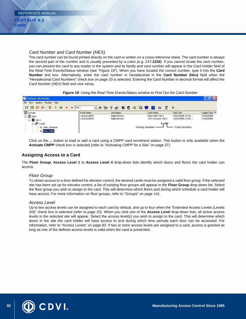
92 Manufacturing Access Control Since 1985
CENTAUR 4.2Cards
REFERENCE MANUAL
Card Number and Card Number (HEX)The card number can be found printed directly on the card or written on a cross-reference sheet. The card number is alwaysthe second part of the number and is usually preceded by a colon (e.g. 247:1234). If you cannot locate the card number,you can present the card to any reader in the system and its family and card number will appear in the Card Holder field ofthe Real-Time Events/Status window (see “Figure 19”). When you have located the correct number, type it into the CardNumber text box. Alternatively, enter the card number in hexadecimal in the Card Number (Hex) field when the“Hexadecimal Card Numbers” check box on page 33 is selected. Entering the Card Number in decimal format will affect theCard Number (HEX) field and vice versa.
Figure 19: Using the Real-Time Events/Status window to Find Out the Card Number
Click on the ... button to load or add a card using a CMPP card enrolment station. This button is only available when theActivate CMPP check box is selected (refer to “Activating CMPP for a Site” on page 37).
Assigning Access to a CardThe Floor Group, Access Level 1 to Access Level 4 drop-down lists identify which doors and floors the card holder canaccess.
Floor GroupTo obtain access to a door defined for elevator control, the desired cards must be assigned a valid floor group. If the selectedsite has been set up for elevator control, a list of existing floor groups will appear in the Floor Group drop-down list. Selectthe floor group you wish to assign to the card. This will determine which floors and during which schedule a card holder willhave access. For more information on floor groups, refer to “Groups” on page 141.
Access LevelUp to two access levels can be assigned to each card by default, and up to four when the “Extended Access Levels (Levels3/4)” check box is selected (refer to page 33). When you click one of the Access Level drop-down lists, all active accesslevels in the selected site will appear. Select the access level(s) you wish to assign to the card. This will determine whichdoors in the site the card holder will have access to and during which time periods each door can be accessed. Forinformation, refer to “Access Levels” on page 83. If two or more access levels are assigned to a card, access is granted aslong as one of the defined access levels is valid when the card is presented.
Family Number Card Number

93Manufacturing Access Control Since 1985
CENTAUR 4.2Cards
REFERENCE MANUAL
Setting Card OptionsThe following check boxes can be used to enable or disable the corresponding options or features.
P.I.N.If the Use Keypad check box has been selected (see Use Keypad on page 93), the card holder will have to type the P.I.N.(Personal Identification Number) recorded in the P.I.N. text box on the system keypad. The P.I.N. can be from four to eightdigits in length and each digit can be any numerical value from zero to nine. The P.I.N. length is also a function of the keypadhardware being used. If desired, Centaur can automatically generate a unique P.I.N. for you. To do so, click the drop-downarrow to the right of the P.I.N. text field and select the desired P.I.N. length.
Card TracedTrack a card holder’s movements by generating a Card Traced event in addition to the Access Granted or Access Deniedevent every time the card is used. To enable this feature, select the Card Traced check box. You can use Centaur’s reportgeneration feature to generate a report of all the Card Traced events. The Card Traced event can also be used to activatea device such as a relay. The relay can be connected to a signalling device, warning the operator that a card with the CardTraced feature enabled has been presented to a reader. For more information, refer to “Events” on page 133.
Extended AccessWhen a card holder is granted access to a door, the door will remain unlocked for the period defined by the door’s “UnlockTime” (see page 74). When the Extended Access check box is selected, the door will remain unlocked for the duration ofthe door’s “Extended Access” (see page 75) in addition to its Unlock Time. This option is particularly useful for individualsthat may require more time to access the door.
Example: A card holder is granted access to the front door with an Unlock Time of 15 seconds and an Extended Accesstime of 30 seconds. If the option is enabled, the door will remain unlocked for 45 seconds instead of only 15 seconds.
Use KeypadThis option is used when a card holder presents their card to a reader that is accompanied by a keypad on the same sideof the door. If the Use Keypad check box is selected, the card holder will have to enter a “P.I.N.” (see page 93) on the keypadafter presenting their card to the reader before being granted access.
Anti-passback OverrideWhen the Anti-passback Override check box is selected, all the controllers in the site will ignore the anti-passback statusof the card (see “Enabling Controller Anti-passback” on page 60).
Interlock OverrideAn interlock installation consists of two doors each controlled by a reader. Access will not be granted to a door in thisconfiguration if the other door is already open or unlock. With the Interlock Override feature enabled, the card holder doesnot have to wait for both doors to be closed in order to access a door using the interlock feature. When using this option andaccess is granted, the controller will generate an Access Granted - Interlock Override event. Also refer to “Assigning anInterlock Input” on page 77.

94 Manufacturing Access Control Since 1985
CENTAUR 4.2Cards
REFERENCE MANUAL
Selecting Card StatusEach card can be tagged with one of five status levels. These status levels will determine when a card holder’s access card isvalid. Click the Status drop-down list to select one of the following status levels.
ValidAs soon as you click OK, the card’s programmed access privileges are valid and the card holder can begin using their carduntil the status is changed.
Stolen, Invalid, or LostThese status levels allow you to indefinitely revoke a card’s privileges without having to remove it from the database. Assoon as you click OK, the card can no longer be used until the status is changed.
PendingYou can use this status level to create a card prior to the date the card becomes valid or for personnel on contract whichwould require a card to be active for a specific period of time. When you select Pending from the Status drop-down list, theStart Date, End Date, Enable Card Traced, and Days Before End Date options become available. Use the Start Date andEnd Date drop-down lists to select the day, month, and year the card becomes valid and the day, month, and year the cardexpires. The card becomes active at 00:00 of the selected Start Date and expires at 24:00 of the selected End Date. Whenthe Enable Card Traced check box is selected, a card traced event will be generated when the card is presented within thedefined number of days (Days Before End Date) before the End Date.
Typing Additional Card Holder Details From the Card window, select the User Defined Data tab and use these fields to record any additional information about the card holder. For information on how to customize the titles of these fields, refer to “Defining the User Definable Card Fields” on page 32.
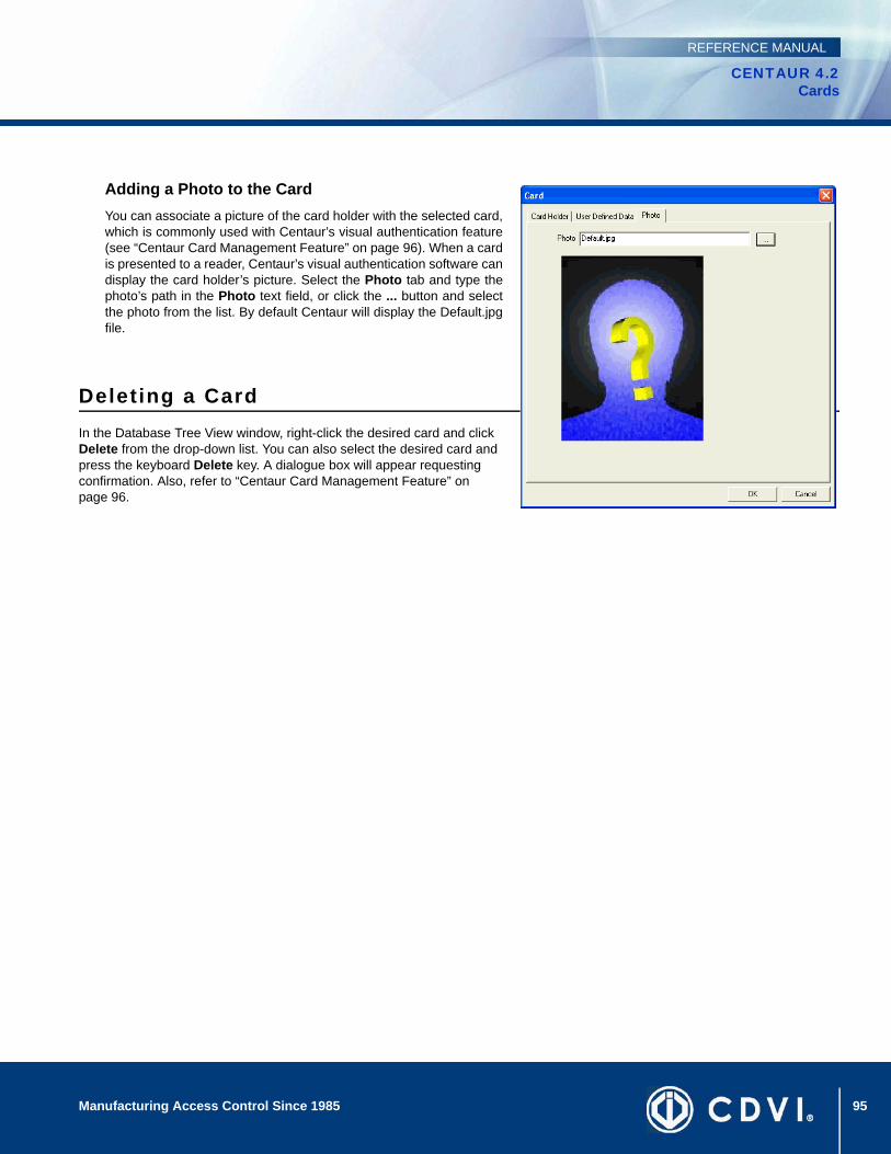
95Manufacturing Access Control Since 1985
CENTAUR 4.2Cards
REFERENCE MANUAL
Adding a Photo to the CardYou can associate a picture of the card holder with the selected card,which is commonly used with Centaur’s visual authentication feature(see “Centaur Card Management Feature” on page 96). When a cardis presented to a reader, Centaur’s visual authentication software candisplay the card holder’s picture. Select the Photo tab and type thephoto’s path in the Photo text field, or click the ... button and selectthe photo from the list. By default Centaur will display the Default.jpgfile.
Deleting a CardIn the Database Tree View window, right-click the desired card and click Delete from the drop-down list. You can also select the desired card and press the keyboard Delete key. A dialogue box will appear requesting confirmation. Also, refer to “Centaur Card Management Feature” on page 96.

96 Manufacturing Access Control Since 1985
CENTAUR 4.2Cards
REFERENCE MANUAL
Centaur Card Management FeatureCentaur Card Management feature is an application that is automatically installed with the Centaur software. It provides an easy to use interface to program the card properties (see “Card Holder Details” on page 91) without having to deal with long card lists in the Database Tree View window and includes an advanced search engine. You can run Centaur Card Management feature without having to run Centaur.
Starting Centaur Card Management FeatureCentaur Card Management feature can be started using one of two methods. To start Centaur Card Management feature from within Centaur, click the Open FrontCard icon from the toolbar (refer to “Toolbar” on page 19), or click the Modules menu and click FrontCard. You can also simultaneously press the Ctrl and F1 keys. The FrontCard Site Selection window appears. In the Site list, select the site whose cards you want to view or modify and click OK.
To start Centaur Card Management feature without Centaur running:
1. From Windows, click Start, Programs, CDV Americas, Centaur, Administration Console, and click FrontCard.
2. From the Logon window, type the appropriate Logon ID and Password. Centaur Card Management feature uses the same logon IDs and passwords as Centaur. If you are logging on from a networked workstation, type the Centaur Server computer’s network name or IP address in the Computer text field. Select the desired language from the Language list.
3. The FrontCard Site Selection window appears. In the Site list, select the site whose cards you want to view or modify and click OK.
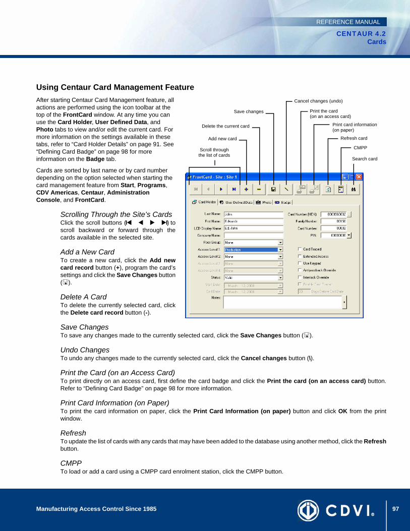
97Manufacturing Access Control Since 1985
CENTAUR 4.2Cards
REFERENCE MANUAL
Using Centaur Card Management FeatureAfter starting Centaur Card Management feature, all actions are performed using the icon toolbar at the top of the FrontCard window. At any time you can use the Card Holder, User Defined Data, and Photo tabs to view and/or edit the current card. For more information on the settings available in these tabs, refer to “Card Holder Details” on page 91. See “Defining Card Badge” on page 98 for more information on the Badge tab.
Cards are sorted by last name or by card number depending on the option selected when starting the card management feature from Start, Programs, CDV Americas, Centaur, Administration Console, and FrontCard.
Scrolling Through the Site’s CardsClick the scroll buttons (I I) toscroll backward or forward through thecards available in the selected site.
Add a New CardTo create a new card, click the Add newcard record button (+), program the card’ssettings and click the Save Changes button( ).
Delete A CardTo delete the currently selected card, clickthe Delete card record button (-).
Save ChangesTo save any changes made to the currently selected card, click the Save Changes button ( ).
Undo ChangesTo undo any changes made to the currently selected card, click the Cancel changes button (\).
Print the Card (on an Access Card)To print directly on an access card, first define the card badge and click the Print the card (on an access card) button.Refer to “Defining Card Badge” on page 98 for more information.
Print Card Information (on Paper)To print the card information on paper, click the Print Card Information (on paper) button and click OK from the printwindow.
RefreshTo update the list of cards with any cards that may have been added to the database using another method, click the Refreshbutton.
CMPPTo load or add a card using a CMPP card enrolment station, click the CMPP button.
Scroll through the list of cards
Add new card
Delete the current card
Search card
Refresh card
Save changes
Cancel changes (undo)
Print card information (on paper)
Print the card(on an access card)
CMPP

98 Manufacturing Access Control Since 1985
CENTAUR 4.2Cards
REFERENCE MANUAL
SearchTo search for a card using specific criteria:Click the Find Card Record icon (binoculars). The Find Card windowappears.From the Field drop-down list, select the desired criteria. The criteria that canbe selected are as follows: Family Number, Card Number, PIN Number,First Name, Last Name, Company, Card Number (Hex), or any of the textfields found in the User Defined Data tab. In the Find text field, type the text that Centaur card management software willsearch for. The text should be representative of the criteria selected in step 2.If you want the search to match exactly what is typed in the Find field, selectthe Exact match check box. Click the Find button.From the Results list, highlight the desired card and click the Go to button toedit the card.
Defining Card BadgeThe card badge is used to define what will be printed directly on the front and back sides of an access card.
1. From the FrontCard window, select the Badge tab.
2. Select a Template from the list or use the Launch Editor button to create a new template (see “Launching the Centaur Badge Editor” on page 99).
3. Select the language to be used from the Language of user defined text drop list.
4. From the Preview’s Front Side and Back Side radio buttons, select the front or back side preview to be displayed.
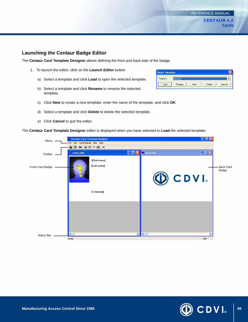
99Manufacturing Access Control Since 1985
CENTAUR 4.2Cards
REFERENCE MANUAL
Launching the Centaur Badge EditorThe Centaur Card Template Designer allows defining the front and back side of the badge.
1. To launch the editor, click on the Launch Editor button.
a) Select a template and click Load to open the selected template.
b) Select a template and click Rename to rename the selected template.
c) Click New to create a new template, enter the name of the template, and click OK.
d) Select a template and click Delete to delete the selected template.
e) Click Cancel to quit the editor.
The Centaur Card Template Designer editor is displayed when you have selected to Load the selected template.
Menu
Toolbar
Front Card Badge Back Card Badge
Status Bar
100 Manufacturing Access Control Since 1985
CENTAUR 4.2Cards
REFERENCE MANUAL
MenuThe menu gives access to the File, Edit, Card Settings, View, and Help menus.
• The File menu gives access to the Template selection, Save, Print, and Exit.
• The Edit menu gives access to the following to add items to the template. For each item selected, click on the screen where the field needs to be located. Click and drag the inserted field to change its location on the badge.
• Add Photo: Allows to add the photo to the badge template.
• Add Card Info: Allows to add predefined card fields from the “Card Holder Details” on page 91 and “Typing Additional Card Holder Details” on page 94. Select a field from the Card Data drop list, and click OK.
• Add Static Text: Allows to add static text to the badge template.
• Add Barcode: Allows to add a barcode.
• The Card Settings menu gives access to the following:
• Background Images: Allows to add a background image to the badge template. Select the background image for the Front and/or the Back of the badge, and click OK.
• Default Font: Allows the selection of the font that will be used for the card fields inserted after the font selection. The Default Font does not affect the fields that are already inserted to the badge template.
• Flip (Portrait / Landscape): Allows to switch the editor layout from portrait to landscape or vice versa.
• The View menu gives access to the following:
• Toolbar: Allows to show or hide the Toolbar.
• Status Bar: Allows to show or hide the Status Bar.
• Show / Hide Front Side: Allows to show or hide the card badge front side.
• Show / Hide Back Side: Allows to show or hide the card badge back side.
• Tile Horizontally: Allows to display the front side of the card badge on top of the back side.
• Tile Vertically: Allows to display the front side of the card badge beside the back side.
• 1 Front Side and 2 Back Side: Allows the selection of either the front side or the back for edition.
• The Help menu gives access to About Centaur Badge Editor window.
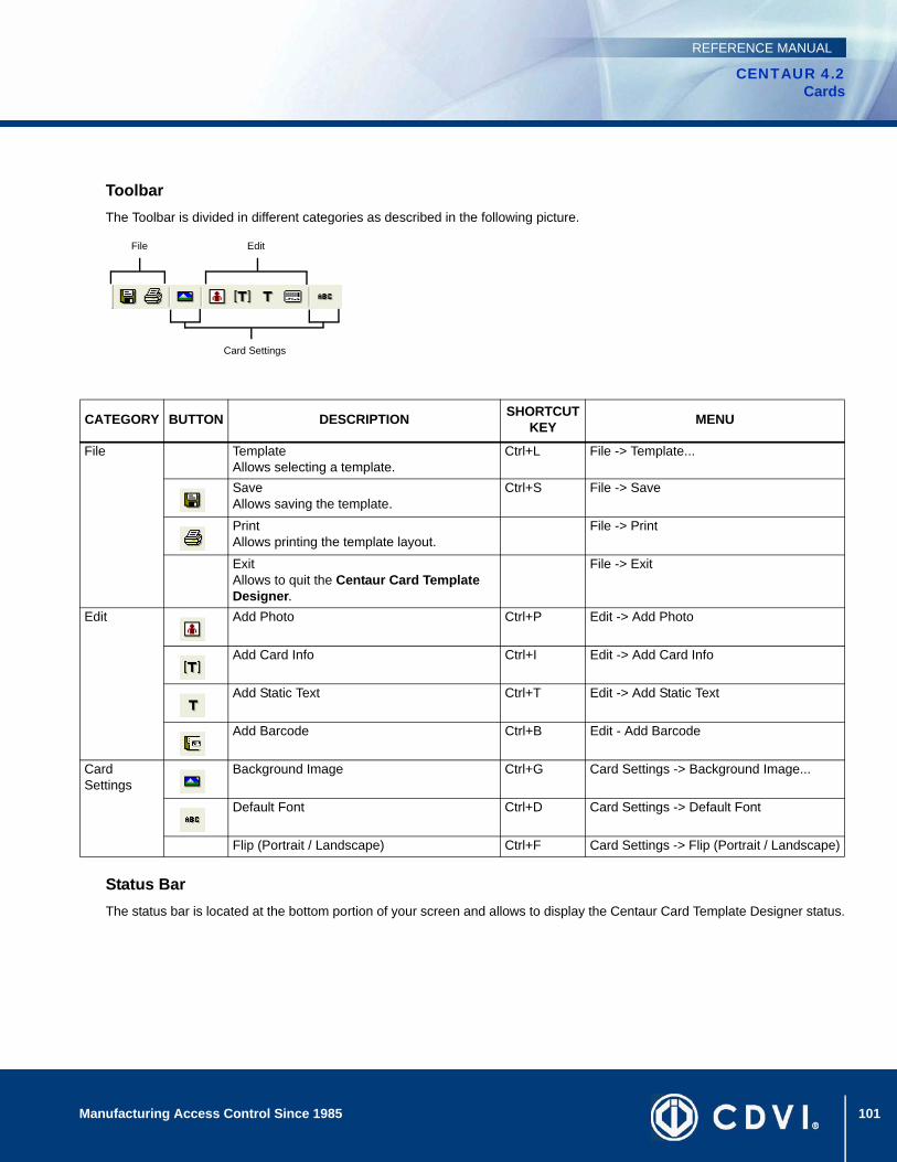
101Manufacturing Access Control Since 1985
CENTAUR 4.2Cards
REFERENCE MANUAL
ToolbarThe Toolbar is divided in different categories as described in the following picture.
Status BarThe status bar is located at the bottom portion of your screen and allows to display the Centaur Card Template Designer status.
CATEGORY BUTTON DESCRIPTION SHORTCUT KEY MENU
File TemplateAllows selecting a template.
Ctrl+L File -> Template...
SaveAllows saving the template.
Ctrl+S File -> Save
PrintAllows printing the template layout.
File -> Print
ExitAllows to quit the Centaur Card Template Designer.
File -> Exit
Edit Add Photo Ctrl+P Edit -> Add Photo
Add Card Info Ctrl+I Edit -> Add Card Info
Add Static Text Ctrl+T Edit -> Add Static Text
Add Barcode Ctrl+B Edit - Add Barcode
Card Settings
Background Image Ctrl+G Card Settings -> Background Image...
Default Font Ctrl+D Card Settings -> Default Font
Flip (Portrait / Landscape) Ctrl+F Card Settings -> Flip (Portrait / Landscape)
File Edit
Card Settings
102 Manufacturing Access Control Since 1985
CENTAUR 4.2Cards
REFERENCE MANUAL
Centaur Card Import/Export FeatureCentaur includes a card import and export feature which enables you to export Centaur card data to a .csv file or import a .csv file containing card data into Centaur’s card database. This application can be useful, for example, if you require several card holders to have access to more than one site. After creating all the cards in one site, export the cards into a .csv file from the site containing the desired cards. Then import the .csv file you created into the desired sites.
Starting the Centaur Card Import/Export FeatureCentaur’s Card Import/Export feature can be started using one of four methods. To start this feature from within Centaur, click the Open Card Import/Export icon from the toolbar, or click Modules and click Card Import/Export. You can also simultaneously press the Ctrl and F2 keys.
To start Centaur Card Import/Export feature without Centaur running:
1. Click Start, Programs, CDV Americas, Centaur, Administration Console, and click Card Import-Export.
2. From the Logon window, type the appropriate Logon ID and Password. Centaur Card Import/Export feature uses the same logon IDs and passwords as Centaur.
3. Click OK.
Exporting Cards
4. After starting Centaur Card Import/Export feature, click Next.
5. Select Export Cards, click Next, and click Next again.
6. Select the site that contains the card data that you want to export and click Next.
7. Type the name of the .csv file that you want to create or click the ... button to select a file name and location. Click Next. The default export file location is My Documents.
8. Select a delimiter that will separate the card data fields. If you want the name of each field to appear in the first row (i.e. last name, card number, etc.), select the First row contains field names check box. Click Next.
9. Items in the bottom list box represent data fields that will be exported into the .csv file. Highlight the desired data fields from either list box and click the Add and Remove buttons until the desired data fields appear in the bottom list box. Click Next.
10. Click Finish. A message appears indicating that the information has been successfully exported. Click OK.
103Manufacturing Access Control Since 1985
CENTAUR 4.2Cards
REFERENCE MANUAL
Importing Cards
1. After starting Centaur Card Import/Export feature, click Next.
2. Select Import Cards, click Next, and click Next again.
3. Select the site that you want to import the card data into and click Next.
4. Type the name of the .csv file that you want to import or click the ... button to select a file name and location. Click Next.
5. Select a delimiter that separates the card data fields in the selected .csv file. If the .csv file contains a colon delimiter between the family and card number, select the Use: delimiter for Family/Card number check box. If the .csv file contains field names in the first row, select the First row contains field names check box. If the .csv file contains hexadecimal family numbers, select the Hex Family number check box. Click Next.
6. Select the default access levels and floor group you wish to assign to all the imported cards and click Next. These can be changed afterwards.
7. Items in the bottom list box represent data fields that will be imported into the selected site. Highlight the desired data fields from either list box and click the Add and Remove buttons until the desired data fields appear in the bottom list box. Click Next.
8. You can click Preview to review the data fields that will be imported into the selected site. Click Finish when you are done. A message appears indicating that the information has been successfully imported. Click OK.
If the site you are importing the cards into already contains cards that are also in the .csv file, errors may occur.
You must close and restart the Centaur administration console for all changes to take effect.

104 Manufacturing Access Control Since 1985
CENTAUR 4.2Cards
REFERENCE MANUAL
105
CENTAUR 4.2Access Control Software
Manufacturing Access Control Since 1985
REFERENCE MANUAL
Chapter 10: Elevator Control
What Will I Find?Overview of Elevator Control . . . . . . . . . . . . . . . . . . . . . . . . . . . . . . . . . . . . . . . . . . . . . . . . . . . . . . . . . . . . . . . . . . . . . . . . . . . . . . 106
Using the Centaur software, you can control the access of up to 64 floors per site. Each of the CA-A480 Elevator Controllers can control up to 16 floors and up to eight elevator controllers can be supported by each controller. You can interface the elevator cart’s floor buttons with the elevator controllers’ relays and program them to follow a public access schedule (no card required) or to limit access to individuals with a valid card. Only the floors that have been assigned to the elevator cart’s public access schedule or to a floor group assigned to a card will be active.
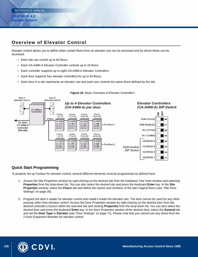
106 Manufacturing Access Control Since 1985
CENTAUR 4.2Elevator Control
REFERENCE MANUAL
Overview of Elevator ControlElevator control allows you to define when certain floors from an elevator cart can be accessed and by whom these can be accessed.
• Each site can control up to 64 floors.
• Each CA-A480-A Elevator Controller controls up to 16 floors.
• Each controller supports up to eight CA-A480-A Elevator Controllers.
• Each door supports four elevator controllers for up to 64 floors.
• Each door in a site represents an elevator cart and each one controls the same floors defined by the site.
Figure 20: Basic Overview of Elevator Controllers
Quick Start ProgrammingTo properly set up Centaur for elevator control, several different elements must be programmed as defined here:
1. Access the Site Properties window by right-clicking on the desired site from the Database Tree View window and selecting Properties from the drop-down list. You can also select the desired site and press the keyboard Enter key. In the Site Properties window, select the Floors tab and define the names and numbers of the site’s logical floors (see “Site Floor Settings” on page 35).
2. Program the door’s reader for elevator control and install it inside the elevator cart. The door cannot be used for any other purpose other than elevator control. Access the Door Properties window by right-clicking on the desired door from the desired controller’s branch within the selected site and clicking Properties from the drop-down list. You can also select the desired door and press the keyboard Enter key. In the Door Properties window of the desired door, select the General tab and set the Door Type to Elevator (see “Door Settings” on page 71). Please note that you cannot use any doors from the 2-Door Expansion Modules for elevator control.
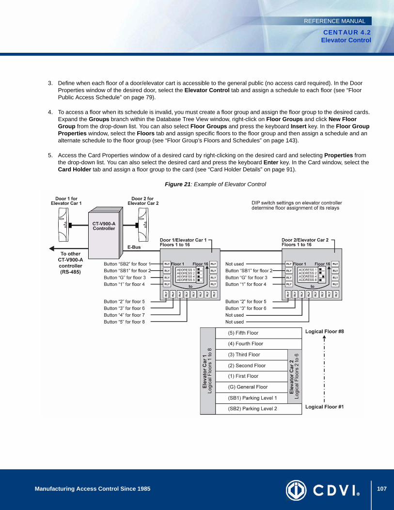
107Manufacturing Access Control Since 1985
CENTAUR 4.2Elevator Control
REFERENCE MANUAL
3. Define when each floor of a door/elevator cart is accessible to the general public (no access card required). In the Door Properties window of the desired door, select the Elevator Control tab and assign a schedule to each floor (see “Floor Public Access Schedule” on page 79).
4. To access a floor when its schedule is invalid, you must create a floor group and assign the floor group to the desired cards. Expand the Groups branch within the Database Tree View window, right-click on Floor Groups and click New Floor Group from the drop-down list. You can also select Floor Groups and press the keyboard Insert key. In the Floor Group Properties window, select the Floors tab and assign specific floors to the floor group and then assign a schedule and an alternate schedule to the floor group (see “Floor Group’s Floors and Schedules” on page 143).
5. Access the Card Properties window of a desired card by right-clicking on the desired card and selecting Properties from the drop-down list. You can also select the desired card and press the keyboard Enter key. In the Card window, select the Card Holder tab and assign a floor group to the card (see “Card Holder Details” on page 91).
Figure 21: Example of Elevator Control

108 Manufacturing Access Control Since 1985
CENTAUR 4.2Elevator Control
REFERENCE MANUAL
109
CENTAUR 4.2Access Control Software
Manufacturing Access Control Since 1985
REFERENCE MANUAL
Chapter 11: Relays
What Will I Find?Adding Relays . . . . . . . . . . . . . . . . . . . . . . . . . . . . . . . . . . . . . . . . . . . . . . . . . . . . . . . . . . . . . . . . . . . . . . . . . . . . . . . . . . . . . . . . . 110 Modifying a Relay . . . . . . . . . . . . . . . . . . . . . . . . . . . . . . . . . . . . . . . . . . . . . . . . . . . . . . . . . . . . . . . . . . . . . . . . . . . . . . . . . . . . . . 110Deleting a Relay . . . . . . . . . . . . . . . . . . . . . . . . . . . . . . . . . . . . . . . . . . . . . . . . . . . . . . . . . . . . . . . . . . . . . . . . . . . . . . . . . . . . . . . 113Display Relay Status and Manual Controls . . . . . . . . . . . . . . . . . . . . . . . . . . . . . . . . . . . . . . . . . . . . . . . . . . . . . . . . . . . . . . . . . . . 113
The CA-A460-P Relay Expansion Module adds seven additional relays to the CT-V900-A controller. Up to two relay expansion modules can be added to each controller for a total of 16 relays per controller.
Typically, the relays are used to activate alarm sounders or other devices such as lighting control units and air conditioners. The relays can be programmed to follow a schedule or to activate upon the validity of a schedule and disable after a programmed timer has elapsed.
In order to add or create one or more relays, at least one site and one controller must be created. If you have not created a site, please refer to “Sites” on page 23. For more information on setting up a controller, refer to “Controllers” on page 49. When adding relays using the methods described in the following sections, you will be required to select an address for each relay. These addresses represent a specific relay on the selected controller or on a Relay Expansion Module connected to the controller (see “Figure 22” on page 111).
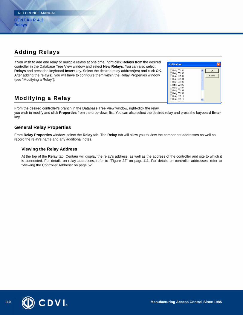
110 Manufacturing Access Control Since 1985
CENTAUR 4.2Relays
REFERENCE MANUAL
Adding RelaysIf you wish to add one relay or multiple relays at one time, right-click Relays from the desired controller in the Database Tree View window and select New Relays. You can also select Relays and press the keyboard Insert key. Select the desired relay address(es) and click OK. After adding the relay(s), you will have to configure them within the Relay Properties window (see “Modifying a Relay”).
Modifying a RelayFrom the desired controller’s branch in the Database Tree View window, right-click the relay you wish to modify and click Properties from the drop-down list. You can also select the desired relay and press the keyboard Enter key.
General Relay PropertiesFrom Relay Properties window, select the Relay tab. The Relay tab will allow you to view the component addresses as well as record the relay’s name and any additional notes.
Viewing the Relay AddressAt the top of the Relay tab, Centaur will display the relay’s address, as well as the address of the controller and site to which itis connected. For details on relay addresses, refer to “Figure 22” on page 111. For details on controller addresses, refer to“Viewing the Controller Address” on page 52.
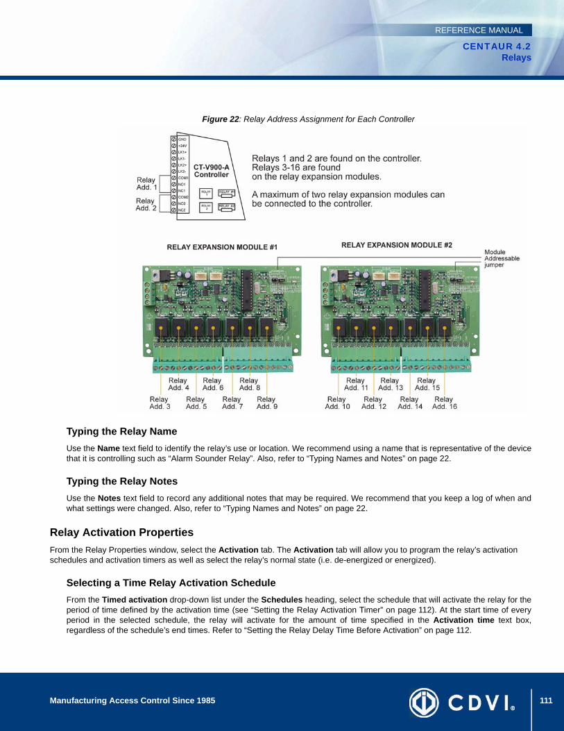
111Manufacturing Access Control Since 1985
CENTAUR 4.2Relays
REFERENCE MANUAL
Figure 22: Relay Address Assignment for Each Controller
Typing the Relay NameUse the Name text field to identify the relay’s use or location. We recommend using a name that is representative of the devicethat it is controlling such as “Alarm Sounder Relay”. Also, refer to “Typing Names and Notes” on page 22.
Typing the Relay NotesUse the Notes text field to record any additional notes that may be required. We recommend that you keep a log of when andwhat settings were changed. Also, refer to “Typing Names and Notes” on page 22.
Relay Activation PropertiesFrom the Relay Properties window, select the Activation tab. The Activation tab will allow you to program the relay’s activation schedules and activation timers as well as select the relay’s normal state (i.e. de-energized or energized).
Selecting a Time Relay Activation ScheduleFrom the Timed activation drop-down list under the Schedules heading, select the schedule that will activate the relay for theperiod of time defined by the activation time (see “Setting the Relay Activation Timer” on page 112). At the start time of everyperiod in the selected schedule, the relay will activate for the amount of time specified in the Activation time text box,regardless of the schedule’s end times. Refer to “Setting the Relay Delay Time Before Activation” on page 112.
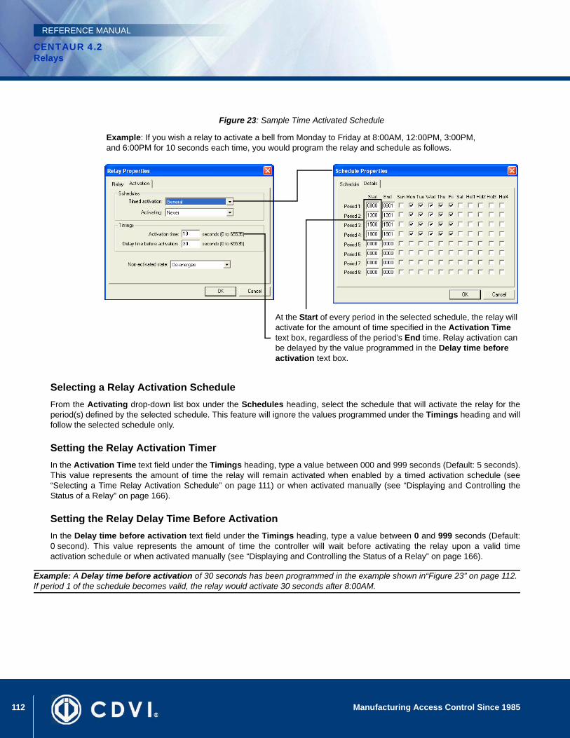
112 Manufacturing Access Control Since 1985
CENTAUR 4.2Relays
REFERENCE MANUAL
Figure 23: Sample Time Activated Schedule
Selecting a Relay Activation ScheduleFrom the Activating drop-down list box under the Schedules heading, select the schedule that will activate the relay for theperiod(s) defined by the selected schedule. This feature will ignore the values programmed under the Timings heading and willfollow the selected schedule only.
Setting the Relay Activation TimerIn the Activation Time text field under the Timings heading, type a value between 000 and 999 seconds (Default: 5 seconds).This value represents the amount of time the relay will remain activated when enabled by a timed activation schedule (see“Selecting a Time Relay Activation Schedule” on page 111) or when activated manually (see “Displaying and Controlling theStatus of a Relay” on page 166).
Setting the Relay Delay Time Before Activation In the Delay time before activation text field under the Timings heading, type a value between 0 and 999 seconds (Default:0 second). This value represents the amount of time the controller will wait before activating the relay upon a valid timeactivation schedule or when activated manually (see “Displaying and Controlling the Status of a Relay” on page 166).
Example: A Delay time before activation of 30 seconds has been programmed in the example shown in“Figure 23” on page 112. If period 1 of the schedule becomes valid, the relay would activate 30 seconds after 8:00AM.
Example: If you wish a relay to activate a bell from Monday to Friday at 8:00AM, 12:00PM, 3:00PM, and 6:00PM for 10 seconds each time, you would program the relay and schedule as follows.
At the Start of every period in the selected schedule, the relay will activate for the amount of time specified in the Activation Time text box, regardless of the period’s End time. Relay activation can be delayed by the value programmed in the Delay time before activation text box.

113Manufacturing Access Control Since 1985
CENTAUR 4.2Relays
REFERENCE MANUAL
Setting the Relay’s Non-Activated StateFrom the Non-activated state drop-down list, select the appropriate normal state.
De-energizedThe relay output is energized when activated. This means the selected relay output on the controller will remain de-energizeduntil activated by a schedule or manually (see “Displaying and Controlling the Status of a Relay” on page 166). Whenactivated, the controller will change the state from off to on.
EnergizedThe relay output is de-energized when activated. This means the selected relay output on the controller will remain energizeduntil activated by a schedule or manually (see “Displaying and Controlling the Status of a Relay” on page 166). Whenactivated, the controller will change the state from on to off.
Deleting a RelayTo delete an existing relay, right-click the relay from the appropriate controller’s branch in the Database Tree View window, and click Delete from the list. You can also select the desired relay and press the keyboard Delete key. A dialogue box will appear requesting confirmation.
Display Relay Status and Manual ControlsWhen you click on the Relay Status icon from the tool bar, Centaur will display the current (live) status of the relays in the system. If you wish to manually change the status of a relay, right-click the desired relay. You can also use the Shift or Ctrl keys to select multiple relays if you wish to modify several relays in the same manner at once and then right-click on any of the selected relays. A drop-down list will appear. Select one of the actions from the list. For more information, refer to “Displaying and Controlling the Status of a Relay” on page 166.

114 Manufacturing Access Control Since 1985
CENTAUR 4.2Relays
REFERENCE MANUAL
115
CENTAUR 4.2Access Control Software
Manufacturing Access Control Since 1985
REFERENCE MANUAL
Chapter 12: Inputs
What Will I Find?Connecting Inputs . . . . . . . . . . . . . . . . . . . . . . . . . . . . . . . . . . . . . . . . . . . . . . . . . . . . . . . . . . . . . . . . . . . . . . . . . . . . . . . . . . . . . . 116Adding Inputs . . . . . . . . . . . . . . . . . . . . . . . . . . . . . . . . . . . . . . . . . . . . . . . . . . . . . . . . . . . . . . . . . . . . . . . . . . . . . . . . . . . . . . . . . . 119Modifying an Input . . . . . . . . . . . . . . . . . . . . . . . . . . . . . . . . . . . . . . . . . . . . . . . . . . . . . . . . . . . . . . . . . . . . . . . . . . . . . . . . . . . . . . 119Deleting an Input . . . . . . . . . . . . . . . . . . . . . . . . . . . . . . . . . . . . . . . . . . . . . . . . . . . . . . . . . . . . . . . . . . . . . . . . . . . . . . . . . . . . . . . 124
Each controller includes eight inputs which can be connected using ATZ Zone Doubling to monitor up to 16 input devices. Each controller also supports up to three 2-Door Expansion Modules (CA-A470-A), which provide an additional 4 inputs each. Therefore, each controller can monitor the state of up to 28 inputs.
Typically, the inputs are used to monitor and control the status of door contacts and request for exit devices installed on the controlled door. The inputs can be programmed to follow a schedule, or to activate relays and/or bypass other inputs when triggered. For additional information on how inputs can be used, refer to “Door Inputs and Outputs” on page 76.

116 Manufacturing Access Control Since 1985
CENTAUR 4.2Inputs
REFERENCE MANUAL
Connecting InputsEach controller and its assigned 2-Door Expansion Modules can monitor the state of up to 28 inputs such as magnetic contacts, motion detectors, temperature sensors or other devices. Inputs can be installed to a maximum distance of 1000m (3300ft.) from the controller when using AWG #22 wire. The controller and its assigned 2-Door Expansion Modules can only use one of the following input connection methods.
NC Input ConnectionWhen this option is selected (see Setting the Controller Input Configuration on page 57), the controller will generate an alarm condition when the state of an input is toggled (opened). This set up will not support tamper or wire fault (short circuit) recognition. Connect one device to each input. For address assignment of the 2-Door Expansion Module’s inputs, refer to “Viewing the Input Address” on page 119.
Figure 24: N.C. Input Connection Methods
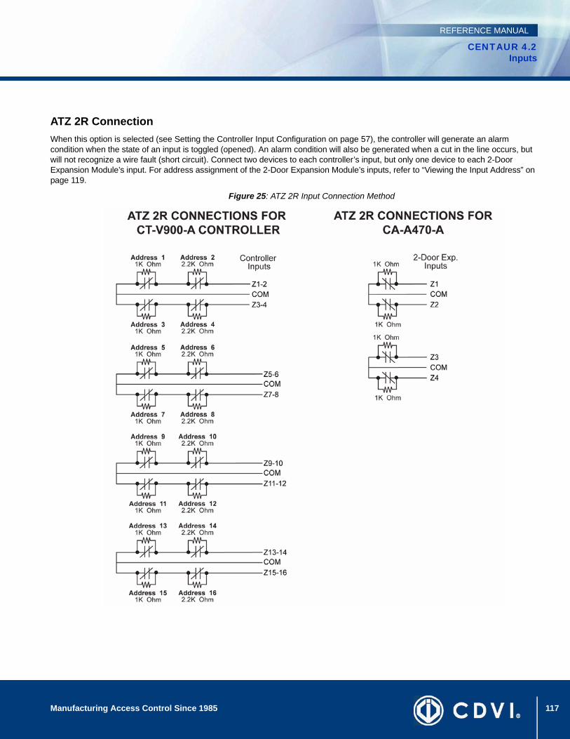
117Manufacturing Access Control Since 1985
CENTAUR 4.2Inputs
REFERENCE MANUAL
ATZ 2R ConnectionWhen this option is selected (see Setting the Controller Input Configuration on page 57), the controller will generate an alarm condition when the state of an input is toggled (opened). An alarm condition will also be generated when a cut in the line occurs, but will not recognize a wire fault (short circuit). Connect two devices to each controller’s input, but only one device to each 2-Door Expansion Module’s input. For address assignment of the 2-Door Expansion Module’s inputs, refer to “Viewing the Input Address” on page 119.
Figure 25: ATZ 2R Input Connection Method

118 Manufacturing Access Control Since 1985
CENTAUR 4.2Inputs
REFERENCE MANUAL
ATZ 3R Connection MethodWhen this option is selected (see Setting the Controller Input Configuration on page 57), the controller will generate an alarm condition when the state of an input is toggled (opened). An alarm condition will also be generated when a wire fault (short circuit) or a cut in the line occurs. Connect two devices to each controller’s input, but only one device to each 2-Door Expansion Module’s input. For address assignment of the 2-Door Expansion Module’s inputs, refer to “Viewing the Input Address” on page 119.
Figure 26: ATZ 3R Input Connection Method

119Manufacturing Access Control Since 1985
CENTAUR 4.2Inputs
REFERENCE MANUAL
Adding InputsIn order to add one or more inputs, at least one site and one controller must be created. If you have not created a site, please refer to “Sites” on page 23. For more information on setting up a controller, refer to “Controllers” on page 49. When adding inputs using the methods described in the following sections, you will be required to select an address for each input. These addresses represent a specific input on the selected controller as described in “Connecting Inputs” on page 116.
To add one input or multiple inputs at one time, right-click Inputs from the desired controller in the Database Tree View window and select New Inputs from the drop-down list. You can also select Inputs and press the keyboard Insert key. Select the desired input address(es) and click OK. After adding the input(s), you will have to configure them within the Input Properties window (see “Modifying an Input” on page 119).
Modifying an InputFrom the desired controller’s branch in the Database Tree View window, right-click the input you wish to modify, and click Properties from the drop-down list. You can also select the desired input and press the keyboard Enter key.
General Input PropertiesFrom the Input Properties window, select the Input tab. The Input tab will allow you to view the component addresses as well as record the input name and any additional notes.
Viewing the Input AddressAt the top of the Input tab, Centaur will display the input address, as well as theaddress of the input controller and site. Please note that the DIP switch settingson each CA-A470-A (2-Door Expansion Module) determines the addressassignment of its input terminals as demonstrated in “Figure 27” on page 120.
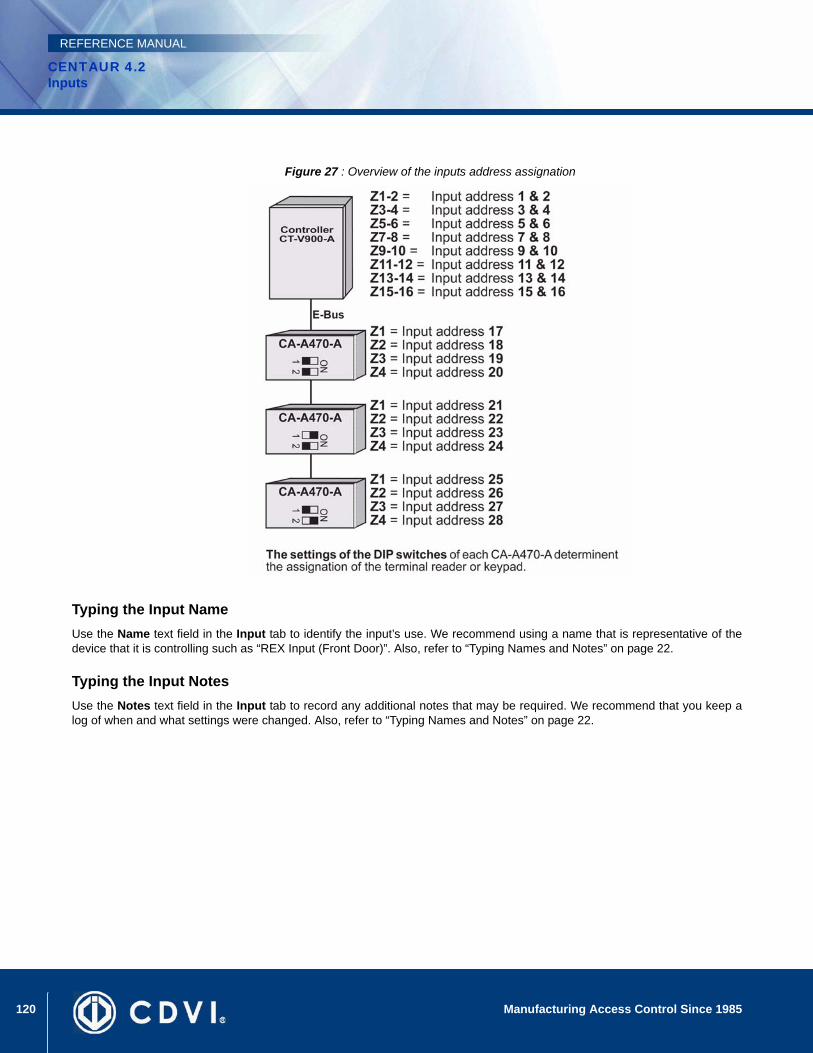
120 Manufacturing Access Control Since 1985
CENTAUR 4.2Inputs
REFERENCE MANUAL
Figure 27 : Overview of the inputs address assignation
Typing the Input NameUse the Name text field in the Input tab to identify the input’s use. We recommend using a name that is representative of thedevice that it is controlling such as “REX Input (Front Door)”. Also, refer to “Typing Names and Notes” on page 22.
Typing the Input NotesUse the Notes text field in the Input tab to record any additional notes that may be required. We recommend that you keep alog of when and what settings were changed. Also, refer to “Typing Names and Notes” on page 22.
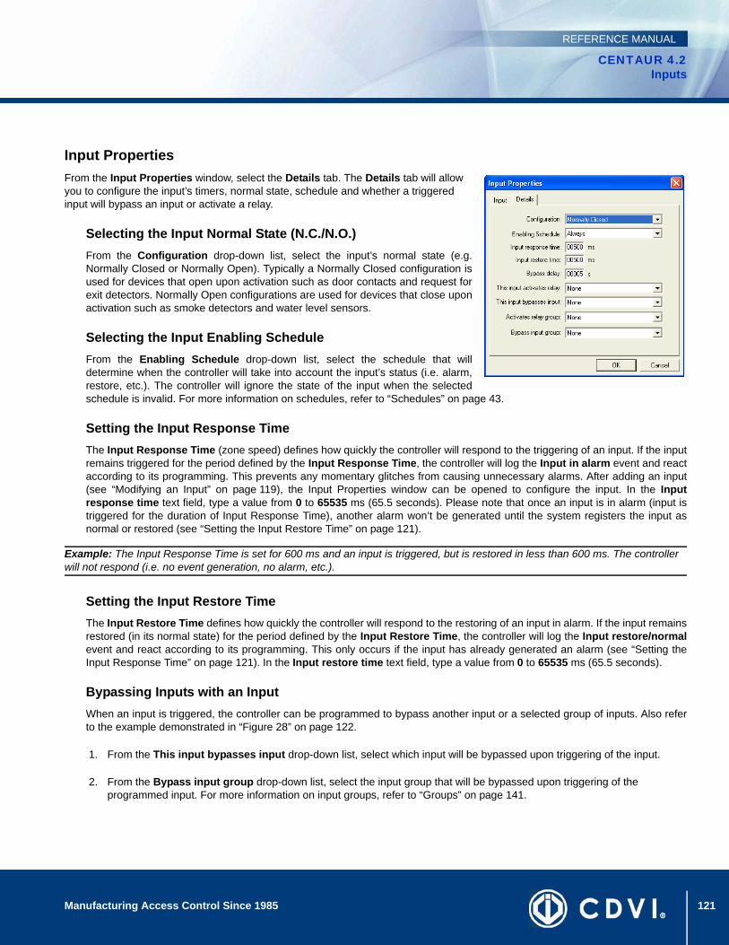
121Manufacturing Access Control Since 1985
CENTAUR 4.2Inputs
REFERENCE MANUAL
Input PropertiesFrom the Input Properties window, select the Details tab. The Details tab will allow you to configure the input’s timers, normal state, schedule and whether a triggered input will bypass an input or activate a relay.
Selecting the Input Normal State (N.C./N.O.)From the Configuration drop-down list, select the input’s normal state (e.g.Normally Closed or Normally Open). Typically a Normally Closed configuration isused for devices that open upon activation such as door contacts and request forexit detectors. Normally Open configurations are used for devices that close uponactivation such as smoke detectors and water level sensors.
Selecting the Input Enabling ScheduleFrom the Enabling Schedule drop-down list, select the schedule that willdetermine when the controller will take into account the input’s status (i.e. alarm,restore, etc.). The controller will ignore the state of the input when the selectedschedule is invalid. For more information on schedules, refer to “Schedules” on page 43.
Setting the Input Response TimeThe Input Response Time (zone speed) defines how quickly the controller will respond to the triggering of an input. If the inputremains triggered for the period defined by the Input Response Time, the controller will log the Input in alarm event and reactaccording to its programming. This prevents any momentary glitches from causing unnecessary alarms. After adding an input(see “Modifying an Input” on page 119), the Input Properties window can be opened to configure the input. In the Inputresponse time text field, type a value from 0 to 65535 ms (65.5 seconds). Please note that once an input is in alarm (input istriggered for the duration of Input Response Time), another alarm won’t be generated until the system registers the input asnormal or restored (see “Setting the Input Restore Time” on page 121).
Example: The Input Response Time is set for 600 ms and an input is triggered, but is restored in less than 600 ms. The controller will not respond (i.e. no event generation, no alarm, etc.).
Setting the Input Restore TimeThe Input Restore Time defines how quickly the controller will respond to the restoring of an input in alarm. If the input remainsrestored (in its normal state) for the period defined by the Input Restore Time, the controller will log the Input restore/normalevent and react according to its programming. This only occurs if the input has already generated an alarm (see “Setting theInput Response Time” on page 121). In the Input restore time text field, type a value from 0 to 65535 ms (65.5 seconds).
Bypassing Inputs with an Input When an input is triggered, the controller can be programmed to bypass another input or a selected group of inputs. Also referto the example demonstrated in “Figure 28” on page 122.
1. From the This input bypasses input drop-down list, select which input will be bypassed upon triggering of the input.
2. From the Bypass input group drop-down list, select the input group that will be bypassed upon triggering of the programmed input. For more information on input groups, refer to “Groups” on page 141.
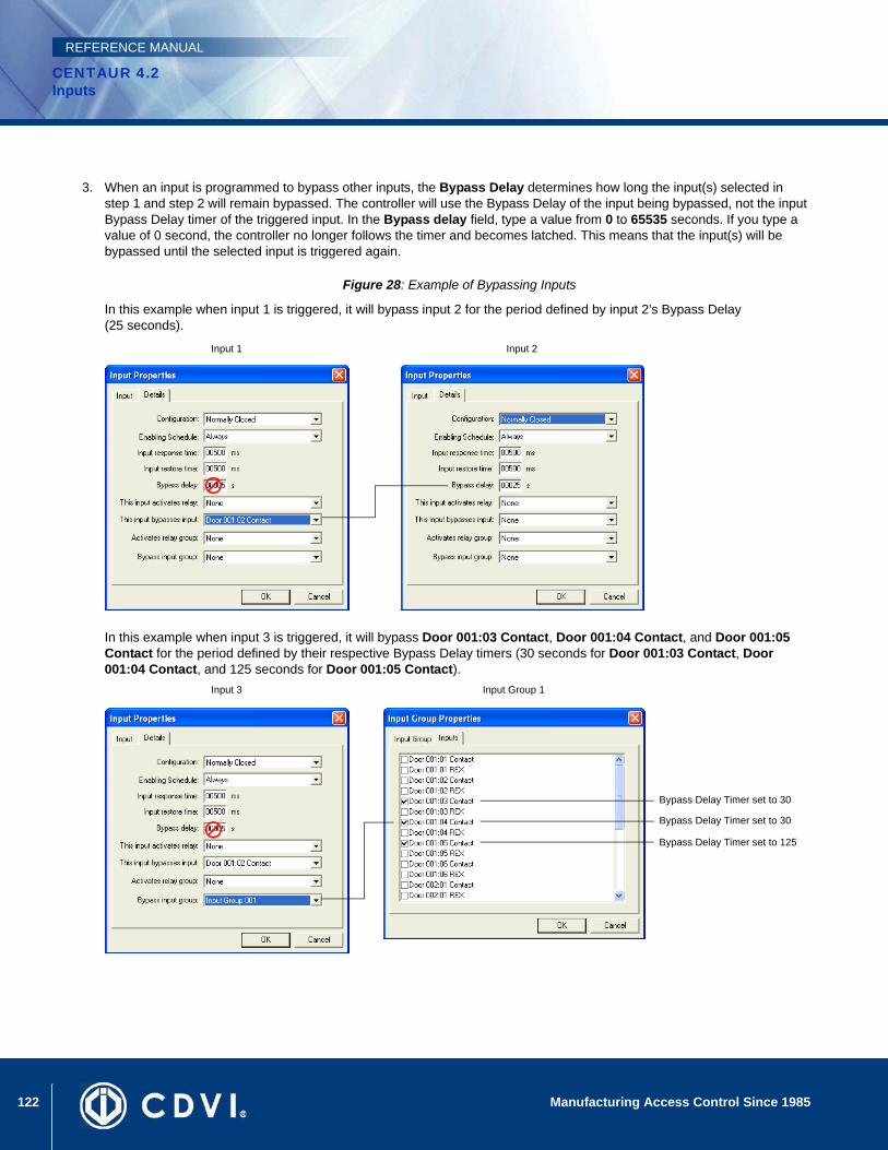
122 Manufacturing Access Control Since 1985
CENTAUR 4.2Inputs
REFERENCE MANUAL
3. When an input is programmed to bypass other inputs, the Bypass Delay determines how long the input(s) selected in step 1 and step 2 will remain bypassed. The controller will use the Bypass Delay of the input being bypassed, not the input Bypass Delay timer of the triggered input. In the Bypass delay field, type a value from 0 to 65535 seconds. If you type a value of 0 second, the controller no longer follows the timer and becomes latched. This means that the input(s) will be bypassed until the selected input is triggered again.
Figure 28: Example of Bypassing Inputs
Input 1 Input 2
Input 3 Input Group 1
In this example when input 3 is triggered, it will bypass Door 001:03 Contact, Door 001:04 Contact, and Door 001:05 Contact for the period defined by their respective Bypass Delay timers (30 seconds for Door 001:03 Contact, Door 001:04 Contact, and 125 seconds for Door 001:05 Contact).
In this example when input 1 is triggered, it will bypass input 2 for the period defined by input 2’s Bypass Delay (25 seconds).
Bypass Delay Timer set to 30
Bypass Delay Timer set to 30
Bypass Delay Timer set to 125
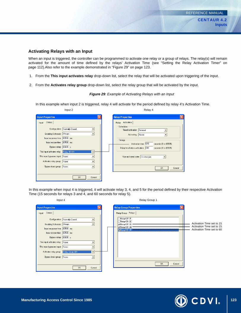
123Manufacturing Access Control Since 1985
CENTAUR 4.2Inputs
REFERENCE MANUAL
Activating Relays with an Input When an input is triggered, the controller can be programmed to activate one relay or a group of relays. The relay(s) will remainactivated for the amount of time defined by the relays’ Activation Time (see “Setting the Relay Activation Timer” onpage 112).Also refer to the example demonstrated in “Figure 29” on page 123.
1. From the This input activates relay drop-down list, select the relay that will be activated upon triggering of the input.
2. From the Activates relay group drop-down list, select the relay group that will be activated by the input.
Figure 29: Example of Activating Relays with an Input
Input 2 Relay 4
Input 4 Relay Group 1
In this example when input 4 is triggered, it will activate relay 3, 4, and 5 for the period defined by their respective Activation Time (15 seconds for relays 3 and 4, and 60 seconds for relay 5).
In this example when input 2 is triggered, relay 4 will activate for the period defined by relay 4‘s Activation Time.
Activation Time set to 15Activation Time set to 15Activation Time set to 60
124 Manufacturing Access Control Since 1985
CENTAUR 4.2Inputs
REFERENCE MANUAL
Deleting an InputTo delete an existing input, right-click the input from the appropriate controller’s branch in the Database Tree View window (left-hand portion of your screen), and click Delete from the list. You can also select the desired input and press the keyboard Delete key. A dialogue box will appear requesting confirmation.

125
CENTAUR 4.2Access Control Software
Manufacturing Access Control Since 1985
REFERENCE MANUAL
Chapter 13: Outputs
What Will I Find?Overview of Output Programming . . . . . . . . . . . . . . . . . . . . . . . . . . . . . . . . . . . . . . . . . . . . . . . . . . . . . . . . . . 126Adding Outputs 127Modifying an Output. . . . . . . . . . . . . . . . . . . . . . . . . . . . . . . . . . . . . . . . . . . . . . . . . . . . . . . . . . . . . . . . . . . . . . . . . . . . . . . . . . . . . 127Deleting an Output . . . . . . . . . . . . . . . . . . . . . . . . . . . . . . . . . . . . . . . . . . . . . . . . . . . . . . . . . . . . . . . . . . . . . . . . . . . . . . . . . . . . . . 131Display Output Status and Manual Controls . . . . . . . . . . . . . . . . . . . . . . . . . . . . . . . . . . . . . . . . . . . . . . . . . . . . . . . . . . . . . . . . . . 131
Each controller includes six multi-function outputs. Each controller also supports up to three 2-Door Expansion Modules (CA-A470-A), which provide an additional 6 outputs each. Therefore, each controller can monitor the state of up to 24 outputs. Typically, the controller’s outputs are used to control the built-in LEDs and buzzers of the card readers and keypads in the system. For example, a red/green indicator on the reader will inform the card holder that access has been granted (changes from red to green), or the reader buzzer will inform the card user that the door has been left open or the door has been forced open. You can individually program each output to follow a specific event as well as determine whether the output will be timed, pulsed, or latched.
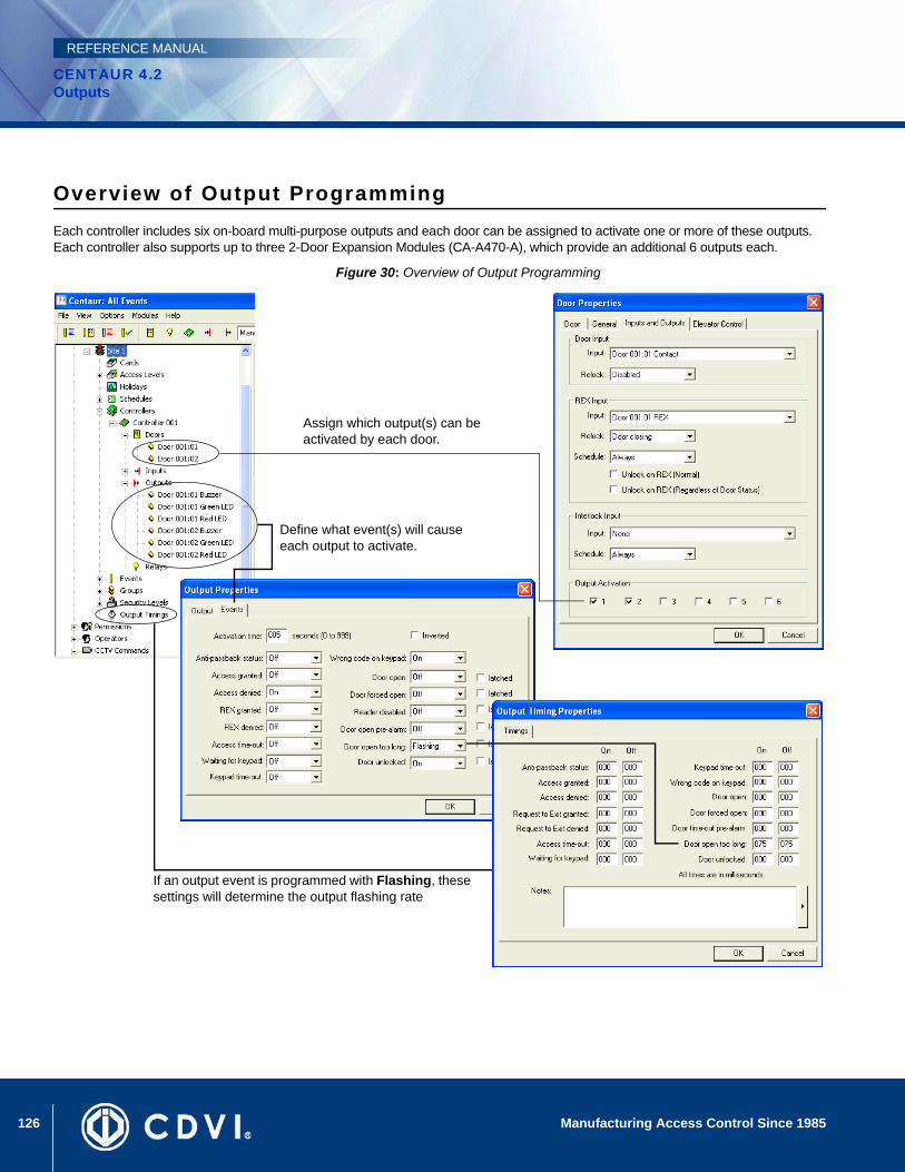
126 Manufacturing Access Control Since 1985
CENTAUR 4.2Outputs
REFERENCE MANUAL
Overview of Output ProgrammingEach controller includes six on-board multi-purpose outputs and each door can be assigned to activate one or more of these outputs. Each controller also supports up to three 2-Door Expansion Modules (CA-A470-A), which provide an additional 6 outputs each.
Figure 30: Overview of Output Programming
Assign which output(s) can be activated by each door.
Define what event(s) will cause each output to activate.
If an output event is programmed with Flashing, these settings will determine the output flashing rate
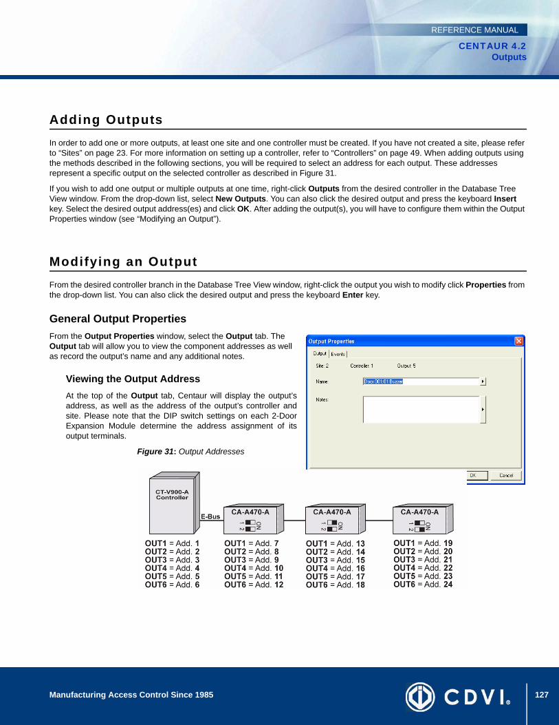
127Manufacturing Access Control Since 1985
CENTAUR 4.2Outputs
REFERENCE MANUAL
Adding OutputsIn order to add one or more outputs, at least one site and one controller must be created. If you have not created a site, please refer to “Sites” on page 23. For more information on setting up a controller, refer to “Controllers” on page 49. When adding outputs using the methods described in the following sections, you will be required to select an address for each output. These addresses represent a specific output on the selected controller as described in Figure 31.
If you wish to add one output or multiple outputs at one time, right-click Outputs from the desired controller in the Database Tree View window. From the drop-down list, select New Outputs. You can also click the desired output and press the keyboard Insert key. Select the desired output address(es) and click OK. After adding the output(s), you will have to configure them within the Output Properties window (see “Modifying an Output”).
Modifying an OutputFrom the desired controller branch in the Database Tree View window, right-click the output you wish to modify click Properties from the drop-down list. You can also click the desired output and press the keyboard Enter key.
General Output PropertiesFrom the Output Properties window, select the Output tab. The Output tab will allow you to view the component addresses as well as record the output’s name and any additional notes.
Viewing the Output AddressAt the top of the Output tab, Centaur will display the output’saddress, as well as the address of the output’s controller andsite. Please note that the DIP switch settings on each 2-DoorExpansion Module determine the address assignment of itsoutput terminals.
Figure 31: Output Addresses
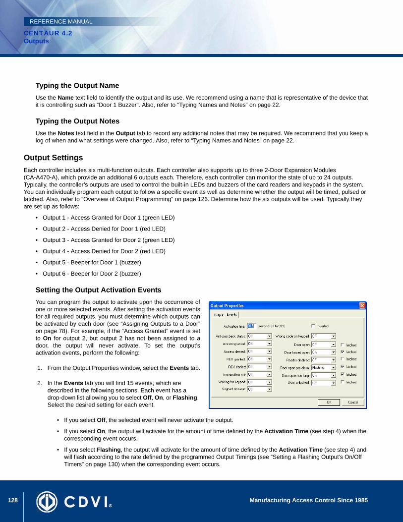
128 Manufacturing Access Control Since 1985
CENTAUR 4.2Outputs
REFERENCE MANUAL
Typing the Output NameUse the Name text field to identify the output and its use. We recommend using a name that is representative of the device thatit is controlling such as “Door 1 Buzzer”. Also, refer to “Typing Names and Notes” on page 22.
Typing the Output NotesUse the Notes text field in the Output tab to record any additional notes that may be required. We recommend that you keep alog of when and what settings were changed. Also, refer to “Typing Names and Notes” on page 22.
Output SettingsEach controller includes six multi-function outputs. Each controller also supports up to three 2-Door Expansion Modules(CA-A470-A), which provide an additional 6 outputs each. Therefore, each controller can monitor the state of up to 24 outputs. Typically, the controller’s outputs are used to control the built-in LEDs and buzzers of the card readers and keypads in the system. You can individually program each output to follow a specific event as well as determine whether the output will be timed, pulsed or latched. Also, refer to “Overview of Output Programming” on page 126. Determine how the six outputs will be used. Typically they are set up as follows:
• Output 1 - Access Granted for Door 1 (green LED)
• Output 2 - Access Denied for Door 1 (red LED)
• Output 3 - Access Granted for Door 2 (green LED)
• Output 4 - Access Denied for Door 2 (red LED)
• Output 5 - Beeper for Door 1 (buzzer)
• Output 6 - Beeper for Door 2 (buzzer)
Setting the Output Activation EventsYou can program the output to activate upon the occurrence ofone or more selected events. After setting the activation eventsfor all required outputs, you must determine which outputs canbe activated by each door (see “Assigning Outputs to a Door”on page 78). For example, if the “Access Granted” event is setto On for output 2, but output 2 has not been assigned to adoor, the output will never activate. To set the output’sactivation events, perform the following:
1. From the Output Properties window, select the Events tab.
2. In the Events tab you will find 15 events, which are described in the following sections. Each event has a drop-down list allowing you to select Off, On, or Flashing. Select the desired setting for each event.
• If you select Off, the selected event will never activate the output.
• If you select On, the output will activate for the amount of time defined by the Activation Time (see step 4) when the corresponding event occurs.
• If you select Flashing, the output will activate for the amount of time defined by the Activation Time (see step 4) and will flash according to the rate defined by the programmed Output Timings (see “Setting a Flashing Output’s On/Off Timers” on page 130) when the corresponding event occurs.
129Manufacturing Access Control Since 1985
CENTAUR 4.2Outputs
REFERENCE MANUAL
3. Six of these events also have a latched check box. If the latched check box is selected, the output will ignore the Activation Time and instead will follow the event that activated it. This means the output will deactivate when the event is restored.
4. In the Activation time text field, type a value from 0 to 999 seconds. If an event is set to On or Flashing (see step 2) and the event occurs, the output will activate for the amount of time defined here unless the latched check box is selected.
5. Selecting the Inverted check box will reverse the output’s normal condition to ON. Therefore, when activated, the output will turn OFF and when the output is deactivated, the output will turn ON.
6. Click OK.
Anti-passback statusIf the Anti-passback feature is enabled (see “Controller Anti-passback Settings” on page 60) and a controller registers twosubsequent Entries or two subsequent Exits, the appropriate “Access Denied - Anti-passback violation” event will begenerated and the output will be activated.
Access grantedThe output can activate when access has been granted to the door following the presentation of a valid card or keypad code.
Access deniedThe output can be activated when access has been denied to the door following the presentation of an invalid card or keypadcode.
REX grantedThe output can activate when a request for exit device (vertical detector) assigned to a door’s REX input (see “Assigning aREX Input (Request for Exit)” on page 76) has been triggered.
REX deniedThe output can be activated when a “REX denied” event occurs other than the “REX Denied - Schedule Invalid” event (i.e.interlock enabled).
Access time-outThe output can be activated when access has been granted, but the door was never opened during the unlock period (see“Unlock Time” on page 74 and “Extended Access” on page 75).
Waiting for keypadWhen both a reader and a keypad are required for access (see “Use Keypad” on page 93), the output can be activated assoon as the reader has granted access.
Keypad time-outWhen both a reader and a keypad are required for access (see “Use Keypad” on page 93), the output can be activated whenthe reader grants access, but no P.I.N. is entered on the keypad within 30 seconds.
Wrong code on keypadThe output can be activated when an incorrect code is entered on a keypad after a valid access card is presented (see “UseKeypad” on page 93).
Door openThe output can be activated whenever an access control door is opened (see “Assigning a Door Input” on page 76). Also,when using this event, the output can be latched.
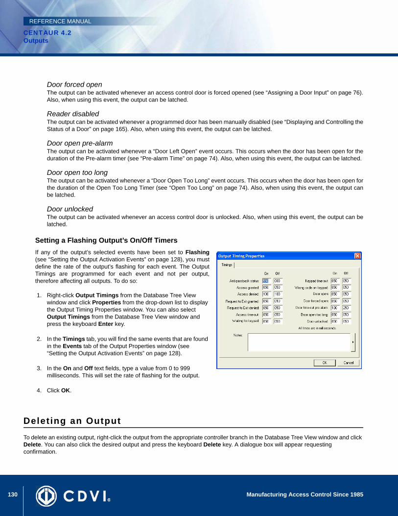
130 Manufacturing Access Control Since 1985
CENTAUR 4.2Outputs
REFERENCE MANUAL
Door forced openThe output can be activated whenever an access control door is forced opened (see “Assigning a Door Input” on page 76).Also, when using this event, the output can be latched.
Reader disabledThe output can be activated whenever a programmed door has been manually disabled (see “Displaying and Controlling theStatus of a Door” on page 165). Also, when using this event, the output can be latched.
Door open pre-alarmThe output can be activated whenever a “Door Left Open” event occurs. This occurs when the door has been open for theduration of the Pre-alarm timer (see “Pre-alarm Time” on page 74). Also, when using this event, the output can be latched.
Door open too longThe output can be activated whenever a “Door Open Too Long” event occurs. This occurs when the door has been open forthe duration of the Open Too Long Timer (see “Open Too Long” on page 74). Also, when using this event, the output canbe latched.
Door unlockedThe output can be activated whenever an access control door is unlocked. Also, when using this event, the output can belatched.
Setting a Flashing Output’s On/Off Timers If any of the output’s selected events have been set to Flashing(see “Setting the Output Activation Events” on page 128), you mustdefine the rate of the output’s flashing for each event. The OutputTimings are programmed for each event and not per output,therefore affecting all outputs. To do so:
1. Right-click Output Timings from the Database Tree View window and click Properties from the drop-down list to display the Output Timing Properties window. You can also select Output Timings from the Database Tree View window and press the keyboard Enter key.
2. In the Timings tab, you will find the same events that are found in the Events tab of the Output Properties window (see “Setting the Output Activation Events” on page 128).
3. In the On and Off text fields, type a value from 0 to 999 milliseconds. This will set the rate of flashing for the output.
4. Click OK.
Deleting an OutputTo delete an existing output, right-click the output from the appropriate controller branch in the Database Tree View window and click Delete. You can also click the desired output and press the keyboard Delete key. A dialogue box will appear requesting confirmation.
131Manufacturing Access Control Since 1985
CENTAUR 4.2Outputs
REFERENCE MANUAL
Display Output Status and Manual ControlsWhen you click on the Output Status icon from the toolbar, Centaur will display the current (live) status of the outputs in the system. If you wish to manually change the status of an output, right-click the desired output. You can also use the Shift or Ctrl keys to select multiple outputs if you wish to modify several outputs in the same manner at once and then right-click on any of the selected outputs. A drop-down list will appear. Select one of the actions from the list. For more information, refer to “Displaying and Controlling the Status of an Output” on page 169.

132 Manufacturing Access Control Since 1985
CENTAUR 4.2Outputs
REFERENCE MANUAL

133
CENTAUR 4.2Access Control Software
Manufacturing Access Control Since 1985
REFERENCE MANUAL
Chapter 14: Events
What Will I Find?Event Definition Overview . . . . . . . . . . . . . . . . . . . . . . . . . . . . . . . . . . . . . . . . . . . . . . . . . . . . . . . . . . . . . . . . . . . . . . . . . . . . . . . . 134Event Schedules and Device Activation . . . . . . . . . . . . . . . . . . . . . . . . . . . . . . . . . . . . . . . . . . . . . . . . . . . . . . . . . . . . . . . . . . . . . 135Alarm Acknowledgement . . . . . . . . . . . . . . . . . . . . . . . . . . . . . . . . . . . . . . . . . . . . . . . . . . . . . . . . . . . . . . . . . . . . . . . . . . . . . . . . . 137E-Mail Activation . . . . . . . . . . . . . . . . . . . . . . . . . . . . . . . . . . . . . . . . . . . . . . . . . . . . . . . . . . . . . . . . . . . . . . . . . . . . . . . . . . . . . . . 139Event-Activated CCTV Control . . . . . . . . . . . . . . . . . . . . . . . . . . . . . . . . . . . . . . . . . . . . . . . . . . . . . . . . . . . . . . . . . . . . . . . . . . . . 140
Every event that occurs in the system can be programmed to perform a series of actions. Schedules can be assigned to each event defining when the event will be displayed on the screen and when it will be saved in the database. Select which device (i.e. relay) can be activated, when it can be activated and the length of activation. A schedule defines when an event will require operator acknowledgement while providing the operator with detailed instructions.
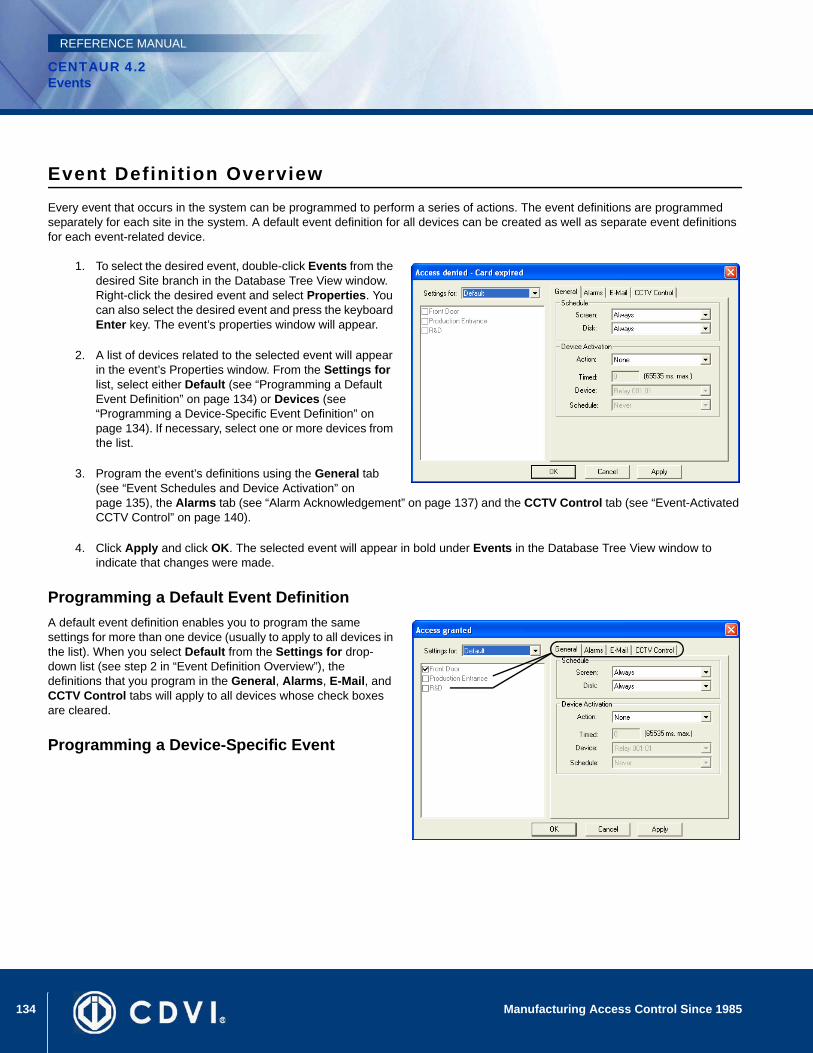
134 Manufacturing Access Control Since 1985
CENTAUR 4.2Events
REFERENCE MANUAL
Event Definit ion OverviewEvery event that occurs in the system can be programmed to perform a series of actions. The event definitions are programmed separately for each site in the system. A default event definition for all devices can be created as well as separate event definitions for each event-related device.
1. To select the desired event, double-click Events from the desired Site branch in the Database Tree View window. Right-click the desired event and select Properties. You can also select the desired event and press the keyboard Enter key. The event’s properties window will appear.
2. A list of devices related to the selected event will appear in the event’s Properties window. From the Settings for list, select either Default (see “Programming a Default Event Definition” on page 134) or Devices (see “Programming a Device-Specific Event Definition” on page 134). If necessary, select one or more devices from the list.
3. Program the event’s definitions using the General tab (see “Event Schedules and Device Activation” on page 135), the Alarms tab (see “Alarm Acknowledgement” on page 137) and the CCTV Control tab (see “Event-Activated CCTV Control” on page 140).
4. Click Apply and click OK. The selected event will appear in bold under Events in the Database Tree View window to indicate that changes were made.
Programming a Default Event DefinitionA default event definition enables you to program the same settings for more than one device (usually to apply to all devices in the list). When you select Default from the Settings for drop-down list (see step 2 in “Event Definition Overview”), the definitions that you program in the General, Alarms, E-Mail, and CCTV Control tabs will apply to all devices whose check boxes are cleared.
Programming a Device-Specific Event
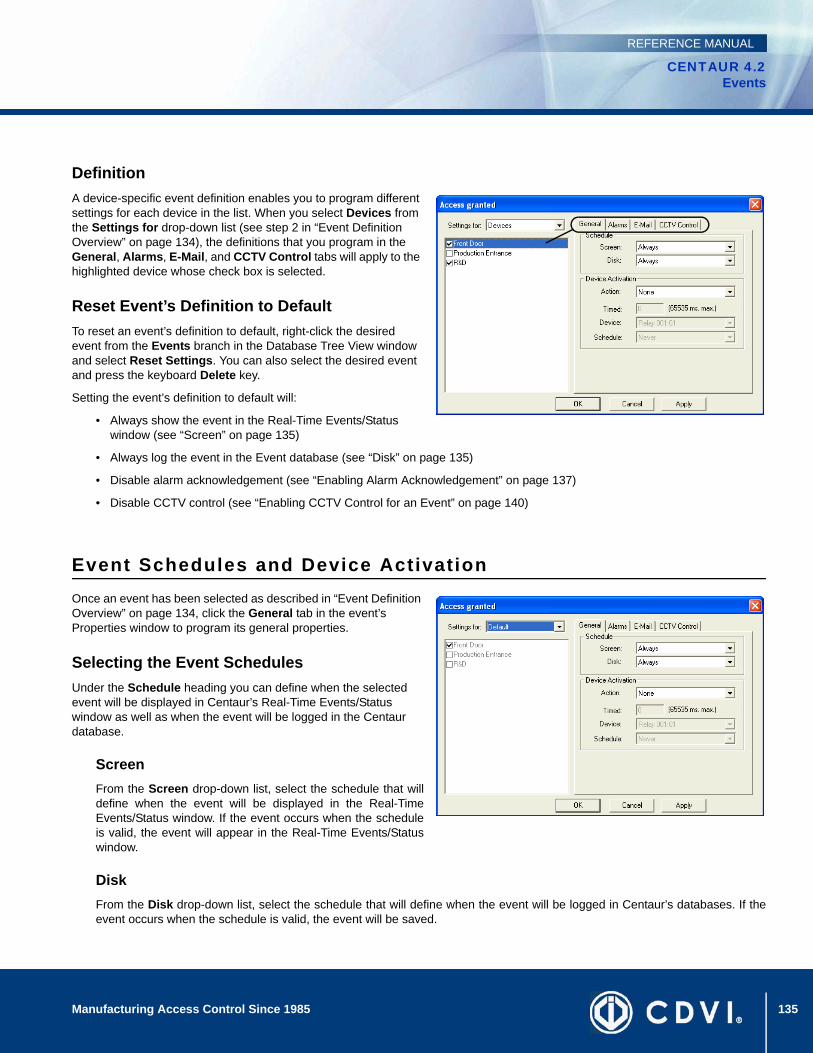
135Manufacturing Access Control Since 1985
CENTAUR 4.2Events
REFERENCE MANUAL
DefinitionA device-specific event definition enables you to program different settings for each device in the list. When you select Devices from the Settings for drop-down list (see step 2 in “Event Definition Overview” on page 134), the definitions that you program in the General, Alarms, E-Mail, and CCTV Control tabs will apply to the highlighted device whose check box is selected.
Reset Event’s Definition to DefaultTo reset an event’s definition to default, right-click the desired event from the Events branch in the Database Tree View window and select Reset Settings. You can also select the desired event and press the keyboard Delete key.
Setting the event’s definition to default will:
• Always show the event in the Real-Time Events/Status window (see “Screen” on page 135)
• Always log the event in the Event database (see “Disk” on page 135)
• Disable alarm acknowledgement (see “Enabling Alarm Acknowledgement” on page 137)
• Disable CCTV control (see “Enabling CCTV Control for an Event” on page 140)
Event Schedules and Device ActivationOnce an event has been selected as described in “Event Definition Overview” on page 134, click the General tab in the event’s Properties window to program its general properties.
Selecting the Event SchedulesUnder the Schedule heading you can define when the selected event will be displayed in Centaur’s Real-Time Events/Status window as well as when the event will be logged in the Centaur database.
ScreenFrom the Screen drop-down list, select the schedule that willdefine when the event will be displayed in the Real-TimeEvents/Status window. If the event occurs when the scheduleis valid, the event will appear in the Real-Time Events/Statuswindow.
DiskFrom the Disk drop-down list, select the schedule that will define when the event will be logged in Centaur’s databases. If theevent occurs when the schedule is valid, the event will be saved.
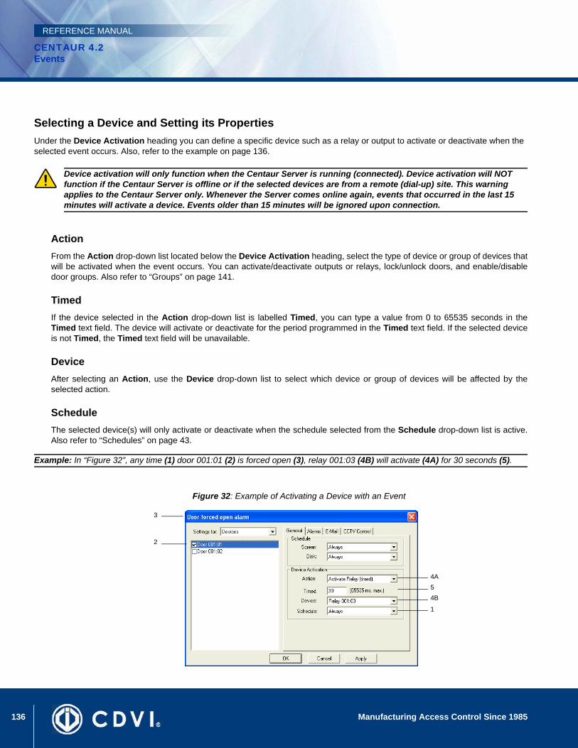
136 Manufacturing Access Control Since 1985
CENTAUR 4.2Events
REFERENCE MANUAL
Selecting a Device and Setting its PropertiesUnder the Device Activation heading you can define a specific device such as a relay or output to activate or deactivate when the selected event occurs. Also, refer to the example on page 136.
ActionFrom the Action drop-down list located below the Device Activation heading, select the type of device or group of devices thatwill be activated when the event occurs. You can activate/deactivate outputs or relays, lock/unlock doors, and enable/disabledoor groups. Also refer to “Groups” on page 141.
TimedIf the device selected in the Action drop-down list is labelled Timed, you can type a value from 0 to 65535 seconds in theTimed text field. The device will activate or deactivate for the period programmed in the Timed text field. If the selected deviceis not Timed, the Timed text field will be unavailable.
DeviceAfter selecting an Action, use the Device drop-down list to select which device or group of devices will be affected by theselected action.
ScheduleThe selected device(s) will only activate or deactivate when the schedule selected from the Schedule drop-down list is active.Also refer to “Schedules” on page 43.
Example: In “Figure 32”, any time (1) door 001:01 (2) is forced open (3), relay 001:03 (4B) will activate (4A) for 30 seconds (5).
Figure 32: Example of Activating a Device with an Event
Device activation will only function when the Centaur Server is running (connected). Device activation will NOT function if the Centaur Server is offline or if the selected devices are from a remote (dial-up) site. This warning applies to the Centaur Server only. Whenever the Server comes online again, events that occurred in the last 15 minutes will activate a device. Events older than 15 minutes will be ignored upon connection.
4A54B
1
3
2
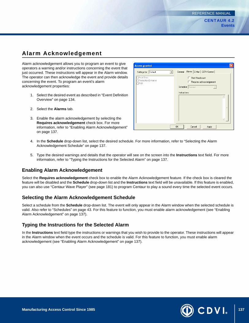
137Manufacturing Access Control Since 1985
CENTAUR 4.2Events
REFERENCE MANUAL
Alarm AcknowledgementAlarm acknowledgement allows you to program an event to give operators a warning and/or instructions concerning the event that just occurred. These instructions will appear in the Alarm window. The operator can then acknowledge the event and provide details concerning the event. To program an event’s alarm acknowledgement properties:
1. Select the desired event as described in “Event Definition Overview” on page 134.
2. Select the Alarms tab.
3. Enable the alarm acknowledgement by selecting the Requires acknowledgement check box. For more information, refer to “Enabling Alarm Acknowledgement” on page 137.
4. In the Schedule drop-down list, select the desired schedule. For more information, refer to “Selecting the Alarm Acknowledgement Schedule” on page 137.
5. Type the desired warnings and details that the operator will see on the screen into the Instructions text field. For more information, refer to “Typing the Instructions for the Selected Alarm” on page 137.
Enabling Alarm AcknowledgementSelect the Requires acknowledgement check box to enable the Alarm Acknowledgement feature. If the check box is cleared the feature will be disabled and the Schedule drop-down list and the Instructions text field will be unavailable. If this feature is enabled, you can also use “Centaur Wave Player” (see page 181) to program Centaur to play a sound every time the selected event occurs.
Selecting the Alarm Acknowledgement ScheduleSelect a schedule from the Schedule drop-down list. The event will only appear in the Alarm window when the selected schedule is valid. Also refer to “Schedules” on page 43. For this feature to function, you must enable alarm acknowledgement (see “Enabling Alarm Acknowledgement” on page 137).
Typing the Instructions for the Selected AlarmIn the Instructions text field type the instructions or warnings that you wish to provide to the operator. These instructions will appear in the Alarm window when the event occurs and the schedule is valid. For this feature to function, you must enable alarm acknowledgement (see “Enabling Alarm Acknowledgement” on page 137).
138 Manufacturing Access Control Since 1985
CENTAUR 4.2Events
REFERENCE MANUAL
Acknowledging Alarms The following details how an operator can acknowledge an alarm.
1. If the event meets the programmed criteria (see “Alarm Acknowledgement” on page 137), the event and its programmed instructions appear in the Alarms window. To play a sound file every time the event occurs, refer to “Centaur Wave Player” on page 181.
2. The operator can acknowledge one event and type any comments, or the operator can acknowledge all events without providing any comments. To acknowledge one event, right-click the event in the Alarm window and select Acknowledge from the list. Go to step 3. To acknowledge all events, right-click any event in the Alarm window and select Acknowledge all from the list. Go to step 4.
3. The Acknowledge Alarm window appears. Type any comments in the Comments text field and click Acknowledge.
4. The “Operator Acknowledge” event appears in the Real-Time Events/Status window. View all acknowledged events by clicking the Acknowledged Events icon from the tool bar. To view any recorded comments, click the Acknowledged Events icon, right-click the desired event in the Real-Time Events/Status window, and click View Comments.
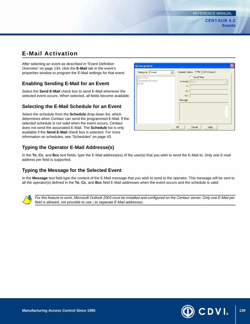
139Manufacturing Access Control Since 1985
CENTAUR 4.2Events
REFERENCE MANUAL
E-Mail ActivationAfter selecting an event as described in “Event Definition Overview” on page 134, click the E-Mail tab in the event’s properties window to program the E-Mail settings for that event.
Enabling Sending E-Mail for an EventSelect the Send E-Mail check box to send E-Mail whenever the selected event occurs. When selected, all fields become available.
Selecting the E-Mail Schedule for an EventSelect the schedule from the Schedule drop-down list, which determines when Centaur can send the programmed E-Mail. If the selected schedule is not valid when the event occurs, Centaur does not send the associated E-Mail. The Schedule list is only available if the Send E-Mail check box is selected. For more information on schedules, see “Schedules” on page 43.
Typing the Operator E-Mail Addresse(s)In the To, Cc, and Bcc text fields, type the E-Mail address(es) of the user(s) that you wish to send the E-Mail to. Only one E-mail address per field is supported.
Typing the Message for the Selected EventIn the Message text field type the content of the E-Mail message that you wish to send to the operator. This message will be sent to all the operator(s) defined in the To, Cc, and Bcc field E-Mail addresses when the event occurs and the schedule is valid.
For this feature to work, Microsoft Outlook 2003 must be installed and configured on the Centaur server. Only one E-Mail per field is allowed, not possible to use ; to separate E-Mail addresses.
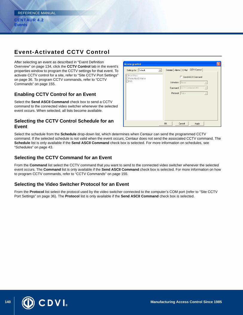
140 Manufacturing Access Control Since 1985
CENTAUR 4.2Events
REFERENCE MANUAL
Event-Activated CCTV ControlAfter selecting an event as described in “Event Definition Overview” on page 134, click the CCTV Control tab in the event’s properties window to program the CCTV settings for that event. To activate CCTV control for a site, refer to “Site CCTV Port Settings” on page 36. To program CCTV commands, refer to “CCTV Commands” on page 155.
Enabling CCTV Control for an EventSelect the Send ASCII Command check box to send a CCTV command to the connected video switcher whenever the selected event occurs. When selected, all lists become available.
Selecting the CCTV Control Schedule for an EventSelect the schedule from the Schedule drop-down list, which determines when Centaur can send the programmed CCTV command. If the selected schedule is not valid when the event occurs, Centaur does not send the associated CCTV command. The Schedule list is only available if the Send ASCII Command check box is selected. For more information on schedules, see “Schedules” on page 43.
Selecting the CCTV Command for an EventFrom the Command list select the CCTV command that you want to send to the connected video switcher whenever the selected event occurs. The Command list is only available if the Send ASCII Command check box is selected. For more information on how to program CCTV commands, refer to “CCTV Commands” on page 155.
Selecting the Video Switcher Protocol for an EventFrom the Protocol list select the protocol used by the video switcher connected to the computer’s COM port (refer to “Site CCTV Port Settings” on page 36). The Protocol list is only available if the Send ASCII Command check box is selected.

141
CENTAUR 4.2Access Control Software
Manufacturing Access Control Since 1985
REFERENCE MANUAL
Chapter 15: Groups
What Will I Find?What Are Groups? . . . . . . . . . . . . . . . . . . . . . . . . . . . . . . . . . . . . . . . . . . . . . . . . . . . . . . . . . . . . . . . . . . . . . . . . . . . . . . . . . . . . . . 142Adding a Group . . . . . . . . . . . . . . . . . . . . . . . . . . . . . . . . . . . . . . . . . . . . . . . . . . . . . . . . . . . . . . . . . . . . . . . . . . . . . . . . . . . . . . . . 142Modifying a Group . . . . . . . . . . . . . . . . . . . . . . . . . . . . . . . . . . . . . . . . . . . . . . . . . . . . . . . . . . . . . . . . . . . . . . . . . . . . . . . . . . . . . . 143Manual Control of Door and Relay Groups . . . . . . . . . . . . . . . . . . . . . . . . . . . . . . . . . . . . . . . . . . . . . . . . . . . . . . . . . . . . . . . . . . . 145. . . . . . . . . . . . . . . . . . . . . . . . . . . . . . . . . . . . . . . . . . . . . . . . . . . . . . . . . . . . . . . . . . . . . . . . . . . . . . . . . . . . . . . . . . . . . . . . . . . . . 145
In the Centaur Access Control System you are often required to select one specific device (i.e. door or relay). Centaur provides you with the added option of creating a group. A group consists of more than one device. Therefore, instead of just selecting one device, you can select a group, which would represent, for example, relays 3, 4, and 5. There are four types of groups: Floor Groups, Door Groups, Input Groups, and Relay Groups.
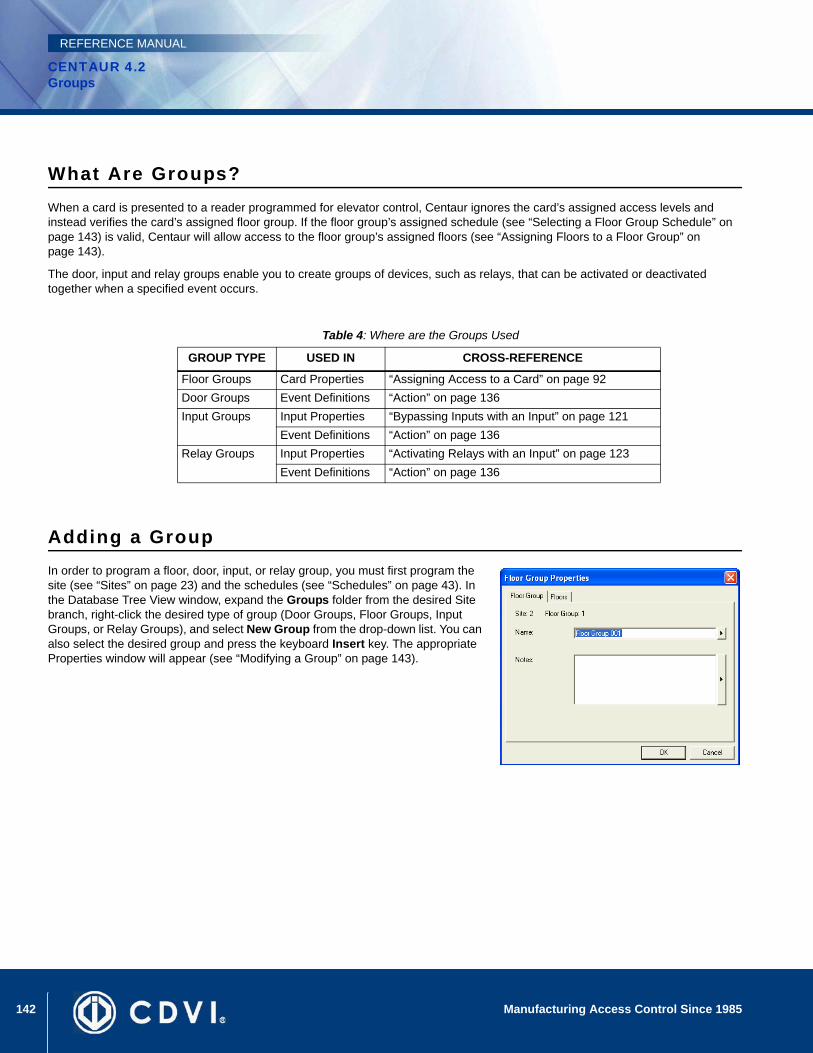
142 Manufacturing Access Control Since 1985
CENTAUR 4.2Groups
REFERENCE MANUAL
What Are Groups?When a card is presented to a reader programmed for elevator control, Centaur ignores the card’s assigned access levels and instead verifies the card’s assigned floor group. If the floor group’s assigned schedule (see “Selecting a Floor Group Schedule” on page 143) is valid, Centaur will allow access to the floor group’s assigned floors (see “Assigning Floors to a Floor Group” on page 143).
The door, input and relay groups enable you to create groups of devices, such as relays, that can be activated or deactivated together when a specified event occurs.
Adding a GroupIn order to program a floor, door, input, or relay group, you must first program the site (see “Sites” on page 23) and the schedules (see “Schedules” on page 43). In the Database Tree View window, expand the Groups folder from the desired Site branch, right-click the desired type of group (Door Groups, Floor Groups, Input Groups, or Relay Groups), and select New Group from the drop-down list. You can also select the desired group and press the keyboard Insert key. The appropriate Properties window will appear (see “Modifying a Group” on page 143).
Table 4: Where are the Groups Used
GROUP TYPE USED IN CROSS-REFERENCE
Floor Groups Card Properties “Assigning Access to a Card” on page 92Door Groups Event Definitions “Action” on page 136Input Groups Input Properties “Bypassing Inputs with an Input” on page 121
Event Definitions “Action” on page 136Relay Groups Input Properties “Activating Relays with an Input” on page 123
Event Definitions “Action” on page 136
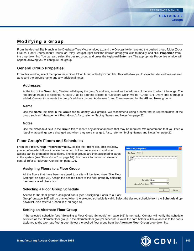
143Manufacturing Access Control Since 1985
CENTAUR 4.2Groups
REFERENCE MANUAL
Modifying a GroupFrom the desired Site branch in the Database Tree View window, expand the Groups folder, expand the desired group folder (Door Groups, Floor Groups, Input Groups, or Relay Groups), right-click the desired group you wish to modify, and click Properties from the drop-down list. You can also select the desired group and press the keyboard Enter key. The appropriate Properties window will appear, allowing you to configure the group.
General Group PropertiesFrom this window, select the appropriate Door, Floor, Input, or Relay Group tab. This will allow you to view the site’s address as well as record the group’s name and any additional notes.
AddressesAt the top of the Group tab, Centaur will display the group’s address, as well as the address of the site to which it belongs. Thefirst group created is assigned “Group: 3” as its address (except for Elevators which will be ‘‘Group: 1‘‘). Every time a group isadded, Centaur increments the group’s address by one. Addresses 1 and 2 are reserved for the All and None groups.
NameUse the Name text field in the Group tab to identify your groups. We recommend using a name that is representative of thegroup such as “Management Floor Group”. Also, refer to “Typing Names and Notes” on page 22.
NotesUse the Notes text field in the Group tab to record any additional notes that may be required. We recommend that you keep alog of what settings were changed and when they were changed. Also, refer to “Typing Names and Notes” on page 22.
Floor Group’s Floors and SchedulesFrom the Floor Group Properties window, select the Floors tab. This will allow you to define which floors in a site that a card holder has access to and when access can be granted to these floors. The floor groups are then assigned to cards in the system (see “Floor Group” on page 92). For more information on elevator control, refer to “Elevator Control” on page 105.
Assigning Floors to a Floor GroupAll the floors that have been assigned to a site will be listed (see “Site FloorSettings” on page 35). Assign the desired floors to the floor group by selectingtheir associated check box.
Selecting a Floor Group ScheduleAccess to the floor group’s assigned floors (see “Assigning Floors to a FloorGroup” on page 143) will be granted when the selected schedule is valid. Select the desired schedule from the Schedule drop-down list. Also refer to “Schedules” on page 43.
Setting an Alternate Floor GroupIf the selected schedule (see “Selecting a Floor Group Schedule” on page 143) is not valid, Centaur will verify the scheduleselected as the alternate floor group. If the alternate floor group’s schedule is valid, the card holder will have access to the floorsassigned to the alternate floor group. Select the desired floor group from the Alternate Floor Group drop-down list.

144 Manufacturing Access Control Since 1985
CENTAUR 4.2Groups
REFERENCE MANUAL
Assigning Devices to a Door, Input, or Relay GroupFrom the Door/Input/Relay Group Properties window, select the Doors, Inputs, or Relays tab. All the devices that have been programmed in the current site will be listed. Assign the desired devices to the group by selecting their associated check box.
Example: In the example below, the selected relay group has been assigned relays 3, 4, and 5 from controller 1.
Figure 33: Example of Programming a Group of Devices
Deleting a GroupFrom the desired Site branch in the Database Tree View window, expand the Groups folder, expand the desired group folder (Door Groups, Floor Groups, Input Groups, or Relay Groups), right-click the desired group you wish to delete, and click Delete from the drop-down list. You can also select the desired group and press the keyboard Delete key. A dialogue box will appear requesting confirmation.
145Manufacturing Access Control Since 1985
CENTAUR 4.2Groups
REFERENCE MANUAL
Manual Control of Door and Relay GroupsThe following describe how you can remotely control a group of doors or relays.
Lock or Unlock a Door GroupTo lock or unlock all doors in a door group, expand the Door Groups folder within the Database Tree View window, right-click the desired door group and select the desired Lock Door Group or Unlock Door Group command from the drop-down list. For more information on the available commands, refer to “Displaying and Controlling the Status of a Door” on page 165.
Enable or Disable a Door GroupTo enable or disable a door group, expand the Door Groups folder within the Database Tree View window, right-click the desired door group, and select the desired Enable Door Group or Disable Door Group command from the drop-down list. When enabled, the door group functions normally. When disabled, the door group will be deactivated and will not be recognized by the system.
Activate or Deactivate a Relay GroupTo activate or deactivate all relays in a relay group, expand the Relay Groups folder within the Database Tree View window, right-click the desired relay group and select the desired Activate Relay Group or Deactivate Relay Group command from the drop-down list. When activated, each relay in the selected relay group will activate for the period specified by the relay’s activation timer (see “Setting the Relay Activation Timer” on page 112).

146 Manufacturing Access Control Since 1985
CENTAUR 4.2Groups
REFERENCE MANUAL
147
CENTAUR 4.2Access Control Software
Manufacturing Access Control Since 1985
REFERENCE MANUAL
Chapter 16: Operators
What Will I Find?Overview of Operators . . . . . . . . . . . . . . . . . . . . . . . . . . . . . . . . . . . . . . . . . . . . . . . . . . . . . . . . . . . . . . . . . . . . . . . . . . . . . . . . . . . 148Adding a Security Level, Permission, or Operator . . . . . . . . . . . . . . . . . . . . . . . . . . . . . . . . . . . . . . . . . . . . . . . . . . . . . . . . . . . . . . 148Modifying a Security Level, Permission, or Operator. . . . . . . . . . . . . . . . . . . . . . . . . . . . . . . . . . . . . . . . . . . . . . . . . . . . . . . . . . . . 149Deleting a Security Level, Permission, or Operator . . . . . . . . . . . . . . . . . . . . . . . . . . . . . . . . . . . . . . . . . . . . . . . . . . . . . . . . . . . . . 154
Operators are personnel authorized to program and/or monitor the Centaur Access Control System through the Centaur software. Each operator authorized to access the Centaur system can be defined with different permissions and security levels. Security levels determine whether an operator can view, modify, and/or delete system characteristics. The system characteristics consist of all the elements found in the Database Tree View window such as controllers, doors, and events. After creating a security level, the security level is assigned to a permission, and the permission is assigned to an operator.
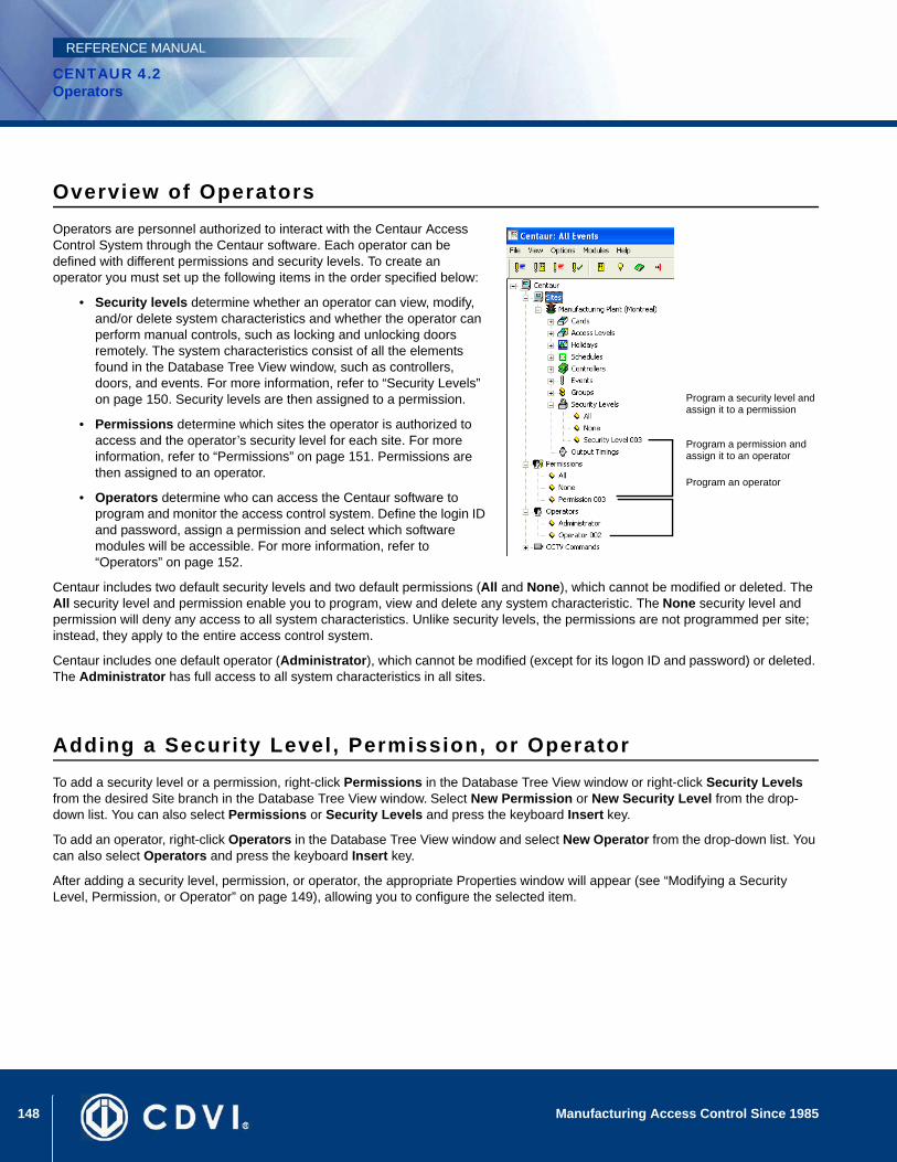
148 Manufacturing Access Control Since 1985
CENTAUR 4.2Operators
REFERENCE MANUAL
Overview of OperatorsOperators are personnel authorized to interact with the Centaur Access Control System through the Centaur software. Each operator can be defined with different permissions and security levels. To create an operator you must set up the following items in the order specified below:
• Security levels determine whether an operator can view, modify, and/or delete system characteristics and whether the operator can perform manual controls, such as locking and unlocking doors remotely. The system characteristics consist of all the elements found in the Database Tree View window, such as controllers, doors, and events. For more information, refer to “Security Levels” on page 150. Security levels are then assigned to a permission.
• Permissions determine which sites the operator is authorized to access and the operator’s security level for each site. For more information, refer to “Permissions” on page 151. Permissions are then assigned to an operator.
• Operators determine who can access the Centaur software to program and monitor the access control system. Define the login ID and password, assign a permission and select which software modules will be accessible. For more information, refer to “Operators” on page 152.
Centaur includes two default security levels and two default permissions (All and None), which cannot be modified or deleted. The All security level and permission enable you to program, view and delete any system characteristic. The None security level and permission will deny any access to all system characteristics. Unlike security levels, the permissions are not programmed per site; instead, they apply to the entire access control system.
Centaur includes one default operator (Administrator), which cannot be modified (except for its logon ID and password) or deleted. The Administrator has full access to all system characteristics in all sites.
Adding a Security Level, Permission, or OperatorTo add a security level or a permission, right-click Permissions in the Database Tree View window or right-click Security Levels from the desired Site branch in the Database Tree View window. Select New Permission or New Security Level from the drop-down list. You can also select Permissions or Security Levels and press the keyboard Insert key.
To add an operator, right-click Operators in the Database Tree View window and select New Operator from the drop-down list. You can also select Operators and press the keyboard Insert key.
After adding a security level, permission, or operator, the appropriate Properties window will appear (see “Modifying a Security Level, Permission, or Operator” on page 149), allowing you to configure the selected item.
Program a security level and assign it to a permission
Program a permission and assign it to an operator
Program an operator
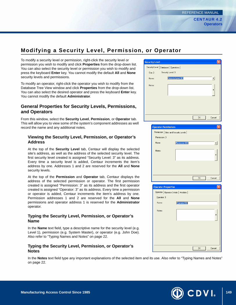
149Manufacturing Access Control Since 1985
CENTAUR 4.2Operators
REFERENCE MANUAL
Modifying a Security Level, Permission, or OperatorTo modify a security level or permission, right-click the security level or permission you wish to modify and click Properties from the drop-down list. You can also select the security level or permission you wish to modify and press the keyboard Enter key. You cannot modify the default All and None security levels and permissions.
To modify an operator, right-click the operator you wish to modify from the Database Tree View window and click Properties from the drop-down list. You can also select the desired operator and press the keyboard Enter key. You cannot modify the default Administrator.
General Properties for Security Levels, Permissions, and OperatorsFrom this window, select the Security Level, Permission, or Operator tab. This will allow you to view some of the system’s component addresses as well record the name and any additional notes.
Viewing the Security Level, Permission, or Operator’s AddressAt the top of the Security Level tab, Centaur will display the selectedsite’s address, as well as the address of the selected security level. Thefirst security level created is assigned “Security Level: 3” as its address.Every time a security level is added, Centaur increments the item’saddress by one. Addresses 1 and 2 are reserved for the All and Nonesecurity levels.
At the top of the Permission and Operator tab, Centaur displays theaddress of the selected permission or operator. The first permissioncreated is assigned “Permission: 3” as its address and the first operatorcreated is assigned “Operator: 3” as its address. Every time a permissionor operator is added, Centaur increments the item’s address by one.Permission addresses 1 and 2 are reserved for the All and Nonepermissions and operator address 1 is reserved for the Administratoroperator.
Typing the Security Level, Permission, or Operator’s NameIn the Name text field, type a descriptive name for the security level (e.g.Level 1), permission (e.g. System Master), or operator (e.g. John Doe).Also refer to “Typing Names and Notes” on page 22.
Typing the Security Level, Permission, or Operator’s NotesIn the Notes text field type any important explanations of the selected item and its use. Also refer to “Typing Names and Notes”on page 22.
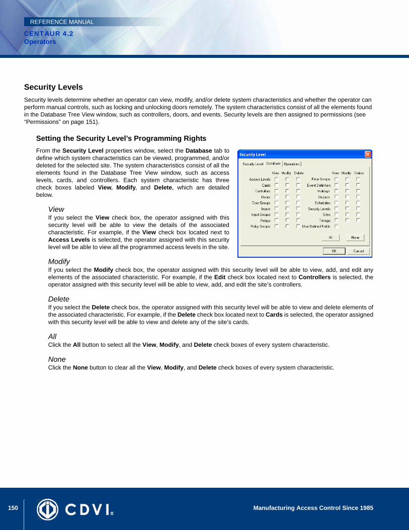
150 Manufacturing Access Control Since 1985
CENTAUR 4.2Operators
REFERENCE MANUAL
Security LevelsSecurity levels determine whether an operator can view, modify, and/or delete system characteristics and whether the operator can perform manual controls, such as locking and unlocking doors remotely. The system characteristics consist of all the elements found in the Database Tree View window, such as controllers, doors, and events. Security levels are then assigned to permissions (see “Permissions” on page 151).
Setting the Security Level’s Programming RightsFrom the Security Level properties window, select the Database tab todefine which system characteristics can be viewed, programmed, and/ordeleted for the selected site. The system characteristics consist of all theelements found in the Database Tree View window, such as accesslevels, cards, and controllers. Each system characteristic has threecheck boxes labeled View, Modify, and Delete, which are detailedbelow.
ViewIf you select the View check box, the operator assigned with thissecurity level will be able to view the details of the associatedcharacteristic. For example, if the View check box located next toAccess Levels is selected, the operator assigned with this securitylevel will be able to view all the programmed access levels in the site.
ModifyIf you select the Modify check box, the operator assigned with this security level will be able to view, add, and edit anyelements of the associated characteristic. For example, if the Edit check box located next to Controllers is selected, theoperator assigned with this security level will be able to view, add, and edit the site’s controllers.
DeleteIf you select the Delete check box, the operator assigned with this security level will be able to view and delete elements ofthe associated characteristic. For example, if the Delete check box located next to Cards is selected, the operator assignedwith this security level will be able to view and delete any of the site’s cards.
AllClick the All button to select all the View, Modify, and Delete check boxes of every system characteristic.
NoneClick the None button to clear all the View, Modify, and Delete check boxes of every system characteristic.
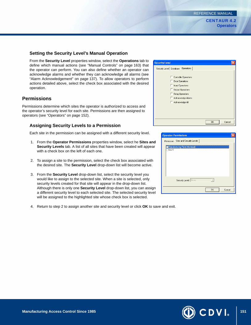
151Manufacturing Access Control Since 1985
CENTAUR 4.2Operators
REFERENCE MANUAL
Setting the Security Level’s Manual OperationFrom the Security Level properties window, select the Operations tab todefine which manual actions (see “Manual Controls” on page 163) thatthe operator can perform. You can also define whether an operator canacknowledge alarms and whether they can acknowledge all alarms (see“Alarm Acknowledgement” on page 137). To allow operators to performactions detailed above, select the check box associated with the desiredoperation.
PermissionsPermissions determine which sites the operator is authorized to access and the operator’s security level for each site. Permissions are then assigned to operators (see “Operators” on page 152).
Assigning Security Levels to a PermissionEach site in the permission can be assigned with a different security level.
1. From the Operator Permissions properties window, select he Sites and Security Levels tab. A list of all sites that have been created will appear with a check box on the left of each one.
2. To assign a site to the permission, select the check box associated with the desired site. The Security Level drop-down list will become active.
3. From the Security Level drop-down list, select the security level you would like to assign to the selected site. When a site is selected, only security levels created for that site will appear in the drop-down list. Although there is only one Security Level drop-down list, you can assign a different security level to each selected site. The selected security level will be assigned to the highlighted site whose check box is selected.
4. Return to step 2 to assign another site and security level or click OK to save and exit.
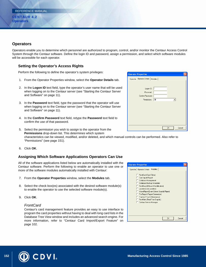
152 Manufacturing Access Control Since 1985
CENTAUR 4.2Operators
REFERENCE MANUAL
OperatorsOperators enable you to determine which personnel are authorized to program, control, and/or monitor the Centaur Access Control System through the Centaur software. Define the login ID and password, assign a permission, and select which software modules will be accessible for each operator.
Setting the Operator’s Access RightsPerform the following to define the operator’s system privileges:
1. From the Operator Properties window, select the Operator Details tab.
2. In the Logon ID text field, type the operator’s user name that will be used when logging on to the Centaur server (see “Starting the Centaur Server and Software” on page 11).
3. In the Password text field, type the password that the operator will use when logging on to the Centaur server (see “Starting the Centaur Server and Software” on page 11).
4. In the Confirm Password text field, retype the Password text field to confirm the use of that password.
5. Select the permission you wish to assign to the operator from the Permissions drop-down list. This determines which system characteristics can be viewed, modified, and/or deleted, and which manual controls can be performed. Also refer to “Permissions” (see page 151).
6. Click OK.
Assigning Which Software Applications Operators Can UseAll of the software applications listed below are automatically installed with theCentaur software. Perform the following to enable an operator to use one ormore of the software modules automatically installed with Centaur:
7. From the Operator Properties window, select the Modules tab.
8. Select the check box(es) associated with the desired software module(s) to enable the operator to use the selected software module(s).
9. Click OK.
FrontCardCentaur’s card management feature provides an easy to use interface toprogram the card properties without having to deal with long card lists in theDatabase Tree View window and includes an advanced search engine. Formore information, refer to “Centaur Card Import/Export Feature” onpage 102.

153Manufacturing Access Control Since 1985
CENTAUR 4.2Operators
REFERENCE MANUAL
Card Import/ExportCentaur’s card import/export feature (server only) enables you to export Centaur card data to a .csv file or import a .csv filecontaining card data into Centaur’s card database. For more information, refer to “Centaur Card Import/Export Feature” onpage 102.
Database ManagementCentaur’s database file management feature (server only) allows you to control and manage the often large and complexdatabase files of the Centaur software. You can back up and restore database files, purge events from selected sites duringspecific periods, limit the size of database files and delete entire database files. For more information, refer to “DatabaseManagement” on page 171.
Database Backup SchedulerCentaur’s database backup scheduler (server only) enables you to schedule regular backups of the Centaur databases. Youcan back up the Main database and the Event database separately, specify the location of the backup files and select howoften (daily, weekly, or monthly) the backup will occur. For more information, refer to “Database Backup Scheduler” onpage 178.
Front Guard (Visual Authentication)Centaur’s visual authentication feature uses events generated in Centaur to retrieve a picture and/or video feed to help youidentify card holders or to view the location where an event has occurred. For more information, refer to Centaur’s VisualAuthentication Software Operator’s Manual.
Locator (User Location)Designed to function with the system’s Global Anti-Passback feature, Centaur’s Anti-Passback Monitoring feature allows youto monitor when card holders enter and exit designated doors in real-time, retrieve card holder information and printcustomizable card holder access reports. For more information, refer to Centaur’s Anti-Passback Monitoring Software OnlineHelp.
WavePlayer (Event Driven Sounds Player)This utility was designed to enable a .wav file to be played on the computer when an event that requires acknowledgementoccurs. The sound can replay at programmed intervals until the alarm is acknowledged. For more information, refer to“Centaur Wave Player” on page 181.
Pro-Report (Report Generation)Centaur’s Report Generation feature provides a user-friendly wizard for generating system and Time and Attendancereports. Generate quick (one-time), pre-defined and scheduled reports for up to 8 different report types. You can also search,group, and sort your reports. For more information, refer to Centaur’s Report Generation Software Operator’s Manual.
FrontView (Real Time Graphic)Centaur’s real-time graphic interface gives you point-and-click control over doors, relays, inputs, outputs, and controllersthrough a graphical floor plan. For more information, refer to Centaur’s Real-Time Graphic Interface Online Help.
Centaur Service ManagerThe Centaur Service Manager allows operators to start and access the Centaur Access Control System. A valid operatorlogin ID and password are required to start Centaur. For more information on how to use the Centaur Service Manager, referto “Starting the Centaur Server and Software” on page 11.
154 Manufacturing Access Control Since 1985
CENTAUR 4.2Operators
REFERENCE MANUAL
Diagnostic ToolCentaur’s new Diagnostic Tool allows you to view your system information to ensure all of the components required to runthe Centaur software have been installed. Within the Diagnostic Tool’s menu, you may save or copy your system informationto a specific folder on your computer or send it directly to our technical support team in the event that you require assistance.This tool is also helpful in assessing which prerequisites your computer may require when upgrading to the latest version ofthe Centaur software.
Deleting a Security Level, Permission, or OperatorTo delete a security level or permission, right-click the security level or permission you wish to delete and click Delete from the drop-down list. You can also select the desired security level or permission and press the keyboard Delete key. A dialogue box appears requesting confirmation. You cannot delete the default All and None security levels and permissions.
To delete an operator, right-click the desired operator from the Database Tree View window and click Delete from the drop-down list. You can also select the desired operator and press the keyboard Delete key. A dialogue box appears requesting confirmation. You cannot delete the default Administrator.

155
CENTAUR 4.2Access Control Software
Manufacturing Access Control Since 1985
REFERENCE MANUAL
Chapter 17: CCTV Commands
What Will I Find?Adding a CCTV Command . . . . . . . . . . . . . . . . . . . . . . . . . . . . . . . . . . . . . . . . . . . . . . . . . . . . . . . . . . . . . . . . . . . . . . . . . . . . . . . 156Modifying a CCTV Command . . . . . . . . . . . . . . . . . . . . . . . . . . . . . . . . . . . . . . . . . . . . . . . . . . . . . . . . . . . . . . . . . . . . . . . . . . . . . 156Deleting a CCTV Command . . . . . . . . . . . . . . . . . . . . . . . . . . . . . . . . . . . . . . . . . . . . . . . . . . . . . . . . . . . . . . . . . . . . . . . . . . . . . . 157
When you activate CCTV control, Centaur can send a detailed CCTV command to a video switcher whenever an event assigned with that command occurs. The CCTV command will tell the video switcher to switch to a specific camera and monitor. You can even set the cameras to tilt, pan, and/or zoom.
Prior to assigning CCTV Commands to an event (refer to “Event-Activated CCTV Control” on page 140), you must program the CCTV commands, which will define how the video switcher will react when selected system events occur.

156 Manufacturing Access Control Since 1985
CENTAUR 4.2CCTV Commands
REFERENCE MANUAL
Adding a CCTV CommandRight-click the CCTV Commands branch in the Database Tree View window and select New CCTV Command from the drop-down list. You can also select CCTV Commands and press the keyboard Insert key. The CCTV Command Properties window will appear (see “Modifying a CCTV Command”), allowing you to configure the CCTV Command.
Modifying a CCTV CommandRight-click the desired CCTV Command from the CCTV Commands branch in the Database Tree View window and select Properties from the drop-down list. You can also select the desired CCTV Command from the CCTV Commands branch in the Database Tree View window and press the keyboard Enter key. The CCTV Command Properties window will appear, allowing you to configure the CCTV Command.
General CCTV Command PropertiesFrom the CCTV Command Properties window, select the General tab to record the CCTV Command’s name and any additional notes.
Typing a CCTV Command’s NameUse the Name text field in the General tab to identify the CCTV Command. Werecommend using a name that is representative of the CCTV Command such as“Cam1 Vid3”. Also, refer to “Typing Names and Notes” on page 22.
Typing a CCTV Command’s NotesUse the Notes text field in the General tab to record any additional notes that may be required. We recommend that you keep alog of what settings were changed and when they were changed. Also, refer to “Typing Names and Notes” on page 22.
CCTV Command SettingsA CCTV Command and its programmed settings are assigned to one or more system event (refer to “Selecting the CCTV Command for an Event” on page 140) and when that event occurs within its assigned schedule (refer to “Selecting the CCTV Control Schedule for an Event” on page 140), Centaur sends the assigned command to the video switcher connected to the COM port selected in the site properties (refer to “Selecting a Computer COM Port for CCTV” on page 36).
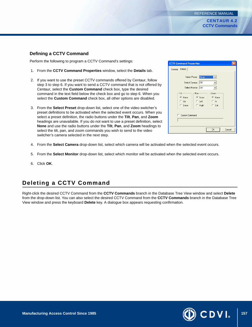
157Manufacturing Access Control Since 1985
CENTAUR 4.2CCTV Commands
REFERENCE MANUAL
Defining a CCTV CommandPerform the following to program a CCTV Command’s settings:
1. From the CCTV Command Properties window, select the Details tab.
2. If you want to use the preset CCTV commands offered by Centaur, follow step 3 to step 6. If you want to send a CCTV command that is not offered by Centaur, select the Custom Command check box, type the desired command in the text field below the check box and go to step 6. When you select the Custom Command check box, all other options are disabled.
3. From the Select Preset drop-down list, select one of the video switcher’s preset definitions to be activated when the selected event occurs. When you select a preset definition, the radio buttons under the Tilt, Pan, and Zoom headings are unavailable. If you do not want to use a preset definition, select None and use the radio buttons under the Tilt, Pan, and Zoom headings to select the tilt, pan, and zoom commands you wish to send to the video switcher’s camera selected in the next step.
4. From the Select Camera drop-down list, select which camera will be activated when the selected event occurs.
5. From the Select Monitor drop-down list, select which monitor will be activated when the selected event occurs.
6. Click OK.
Deleting a CCTV CommandRight-click the desired CCTV Command from the CCTV Commands branch in the Database Tree View window and select Delete from the drop-down list. You can also select the desired CCTV Command from the CCTV Commands branch in the Database Tree View window and press the keyboard Delete key. A dialogue box appears requesting confirmation.

158 Manufacturing Access Control Since 1985
CENTAUR 4.2CCTV Commands
REFERENCE MANUAL
159
CENTAUR 4.2Access Control Software
Manufacturing Access Control Since 1985
REFERENCE MANUAL
Chapter 18: Options
What Will I Find?General Centaur Options . . . . . . . . . . . . . . . . . . . . . . . . . . . . . . . . . . . . . . . . . . . . . . . . . . . . . . . . . . . . . . . . . . . . . . . . . . . . . . . . . 160Event Colour Definitions . . . . . . . . . . . . . . . . . . . . . . . . . . . . . . . . . . . . . . . . . . . . . . . . . . . . . . . . . . . . . . . . . . . . . . . . . . . . . . . . . 161Operator Timeout. . . . . . . . . . . . . . . . . . . . . . . . . . . . . . . . . . . . . . . . . . . . . . . . . . . . . . . . . . . . . . . . . . . . . . . . . . . . . . . . . . . . . . . 162Log File . . . . . . . . . . . . . . . . . . . . . . . . . . . . . . . . . . . . . . . . . . . . . . . . . . . . . . . . . . . . . . . . . . . . . . . . . . . . . . . . . . . . . . . . . . . . . . 162
The Centaur software can be programmed to provide visual and/or auditory feedback when specific events or alarms occur in the system. You can also determine at what frequency (in seconds) that Centaur will update the Real-Time Events/Status window. The colours of each event that appear in the Real-Time Events/Status window can be customized to your needs. You can also set the Centaur administration consoles to automatically log off if no action has occurred after a specified amount of time.
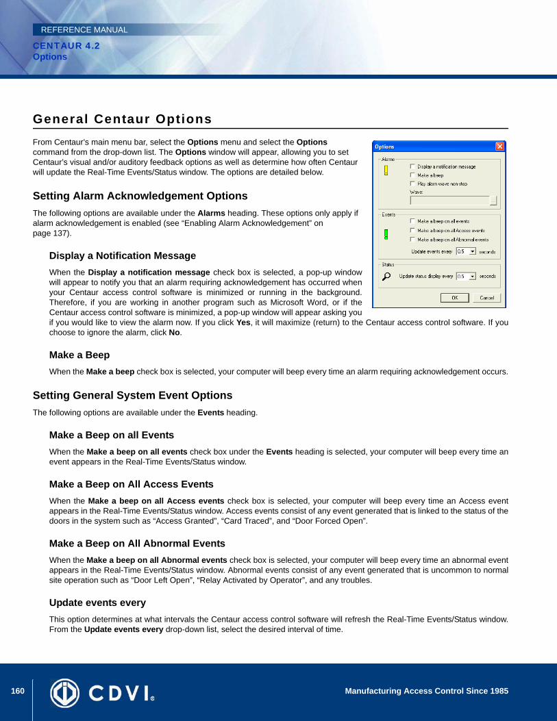
160 Manufacturing Access Control Since 1985
CENTAUR 4.2Options
REFERENCE MANUAL
General Centaur OptionsFrom Centaur’s main menu bar, select the Options menu and select the Options command from the drop-down list. The Options window will appear, allowing you to set Centaur’s visual and/or auditory feedback options as well as determine how often Centaur will update the Real-Time Events/Status window. The options are detailed below.
Setting Alarm Acknowledgement OptionsThe following options are available under the Alarms heading. These options only apply if alarm acknowledgement is enabled (see “Enabling Alarm Acknowledgement” on page 137).
Display a Notification MessageWhen the Display a notification message check box is selected, a pop-up windowwill appear to notify you that an alarm requiring acknowledgement has occurred whenyour Centaur access control software is minimized or running in the background.Therefore, if you are working in another program such as Microsoft Word, or if theCentaur access control software is minimized, a pop-up window will appear asking youif you would like to view the alarm now. If you click Yes, it will maximize (return) to the Centaur access control software. If youchoose to ignore the alarm, click No.
Make a BeepWhen the Make a beep check box is selected, your computer will beep every time an alarm requiring acknowledgement occurs.
Setting General System Event OptionsThe following options are available under the Events heading.
Make a Beep on all Events When the Make a beep on all events check box under the Events heading is selected, your computer will beep every time anevent appears in the Real-Time Events/Status window.
Make a Beep on All Access Events When the Make a beep on all Access events check box is selected, your computer will beep every time an Access eventappears in the Real-Time Events/Status window. Access events consist of any event generated that is linked to the status of thedoors in the system such as “Access Granted”, “Card Traced”, and “Door Forced Open”.
Make a Beep on All Abnormal Events When the Make a beep on all Abnormal events check box is selected, your computer will beep every time an abnormal eventappears in the Real-Time Events/Status window. Abnormal events consist of any event generated that is uncommon to normalsite operation such as “Door Left Open”, “Relay Activated by Operator”, and any troubles.
Update events every This option determines at what intervals the Centaur access control software will refresh the Real-Time Events/Status window.From the Update events every drop-down list, select the desired interval of time.
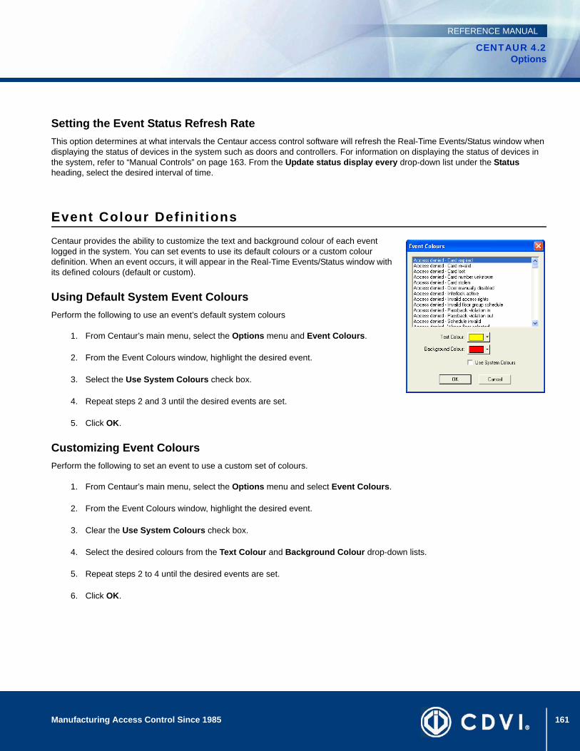
161Manufacturing Access Control Since 1985
CENTAUR 4.2Options
REFERENCE MANUAL
Setting the Event Status Refresh Rate This option determines at what intervals the Centaur access control software will refresh the Real-Time Events/Status window when displaying the status of devices in the system such as doors and controllers. For information on displaying the status of devices in the system, refer to “Manual Controls” on page 163. From the Update status display every drop-down list under the Status heading, select the desired interval of time.
Event Colour Definit ionsCentaur provides the ability to customize the text and background colour of each event logged in the system. You can set events to use its default colours or a custom colour definition. When an event occurs, it will appear in the Real-Time Events/Status window with its defined colours (default or custom).
Using Default System Event ColoursPerform the following to use an event’s default system colours
1. From Centaur’s main menu, select the Options menu and Event Colours.
2. From the Event Colours window, highlight the desired event.
3. Select the Use System Colours check box.
4. Repeat steps 2 and 3 until the desired events are set.
5. Click OK.
Customizing Event ColoursPerform the following to set an event to use a custom set of colours.
1. From Centaur’s main menu, select the Options menu and select Event Colours.
2. From the Event Colours window, highlight the desired event.
3. Clear the Use System Colours check box.
4. Select the desired colours from the Text Colour and Background Colour drop-down lists.
5. Repeat steps 2 to 4 until the desired events are set.
6. Click OK.

162 Manufacturing Access Control Since 1985
CENTAUR 4.2Options
REFERENCE MANUAL
Figure 34: Customizing Event Colours
Operator TimeoutThe Centaur administration consoles can be programmed to log off automatically when no action has occurred within the software (i.e. programming, viewing system status, etc.) for a specified amount of time.
1. From Centaur’s main menu, select the Options menu and select Operator Timeout.
2. The Operator Timeout window will appear. In the Timeout text field, type a value in minutes from 0 to 65536. To disable this feature, type 00000.
3. Click OK.
Log FileCentaur can automatically save a .xml log file of events to your hard drive. This is convenient in the event that you require assistance from our technical support team and a log of recent events is required.
1. From Centaur’s main menu, select the Options menu and select Log File.
2. The Log file options window will appear. Select the Enable Log check box. This feature is disabled when the check box is cleared.
3. In the Log file limit text field, type a value in amount of entries from 10 to 1000.
4. Click OK.
163
CENTAUR 4.2Access Control Software
Manufacturing Access Control Since 1985
REFERENCE MANUAL
Chapter 19: Manual Controls
What Will I Find?Event Display. . . . . . . . . . . . . . . . . . . . . . . . . . . . . . . . . . . . . . . . . . . . . . . . . . . . . . . . . . . . . . . . . . . . . . . . . . . . . . . . . . . . . . . . . . 164Manual Controls. . . . . . . . . . . . . . . . . . . . . . . . . . . . . . . . . . . . . . . . . . . . . . . . . . . . . . . . . . . . . . . . . . . . . . . . . . . . . . . . . . . . . . . . 165
Centaur includes an intuitive toolbar that you can use to display the status of specific output and input devices as well as control the activation and deactivation of those devices. In each site, you can view and control the status of the controllers, doors, inputs, outputs, and relays.
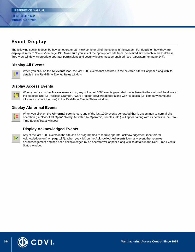
164 Manufacturing Access Control Since 1985
CENTAUR 4.2Manual Controls
REFERENCE MANUAL
Event DisplayThe following sections describe how an operator can view some or all of the events in the system. For details on how they are displayed, refer to “Events” on page 133. Make sure you select the appropriate site from the desired site branch in the Database Tree View window. Appropriate operator permissions and security levels must be enabled (see “Operators” on page 147).
Display All EventsWhen you click on the All events icon, the last 1000 events that occurred in the selected site will appear along with its details in the Real-Time Events/Status window.
Display Access EventsWhen you click on the Access events icon, any of the last 1000 events generated that is linked to the status of the doors in the selected site (i.e. “Access Granted”, “Card Traced”, etc.) will appear along with its details (i.e. company name and information about the user) in the Real-Time Events/Status window.
Display Abnormal EventsWhen you click on the Abnormal events icon, any of the last 1000 events generated that is uncommon to normal site operation (i.e. “Door Left Open”, “Relay Activated by Operator”, troubles, etc.) will appear along with its details in the Real-Time Events/Status window.
Display Acknowledged EventsAny of the last 1000 events in the site can be programmed to require operator acknowledgement (see “Alarm Acknowledgement” on page 137). When you click on the Acknowledged events icon, any event that requires acknowledgement and has been acknowledged by an operator will appear along with its details in the Real-Time Events/Status window.
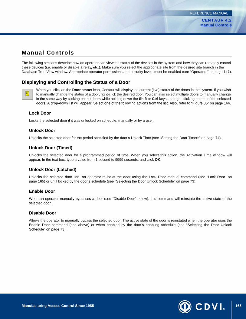
165Manufacturing Access Control Since 1985
CENTAUR 4.2Manual Controls
REFERENCE MANUAL
Manual ControlsThe following sections describe how an operator can view the status of the devices in the system and how they can remotely control these devices (i.e. enable or disable a relay, etc.). Make sure you select the appropriate site from the desired site branch in the Database Tree View window. Appropriate operator permissions and security levels must be enabled (see “Operators” on page 147).
Displaying and Controlling the Status of a DoorWhen you click on the Door status icon, Centaur will display the current (live) status of the doors in the system. If you wish to manually change the status of a door, right-click the desired door. You can also select multiple doors to manually change in the same way by clicking on the doors while holding down the Shift or Ctrl keys and right-clicking on one of the selected doors. A drop-down list will appear. Select one of the following actions from the list. Also, refer to “Figure 35” on page 166.
Lock DoorLocks the selected door if it was unlocked on schedule, manually or by a user.
Unlock DoorUnlocks the selected door for the period specified by the door’s Unlock Time (see “Setting the Door Timers” on page 74).
Unlock Door (Timed)Unlocks the selected door for a programmed period of time. When you select this action, the Activation Time window willappear. In the text box, type a value from 1 second to 9999 seconds, and click OK.
Unlock Door (Latched)Unlocks the selected door until an operator re-locks the door using the Lock Door manual command (see “Lock Door” onpage 165) or until locked by the door’s schedule (see “Selecting the Door Unlock Schedule” on page 73).
Enable DoorWhen an operator manually bypasses a door (see “Disable Door” below), this command will reinstate the active state of theselected door.
Disable DoorAllows the operator to manually bypass the selected door. The active state of the door is reinstated when the operator uses theEnable Door command (see above) or when enabled by the door’s enabling schedule (see “Selecting the Door UnlockSchedule” on page 73).
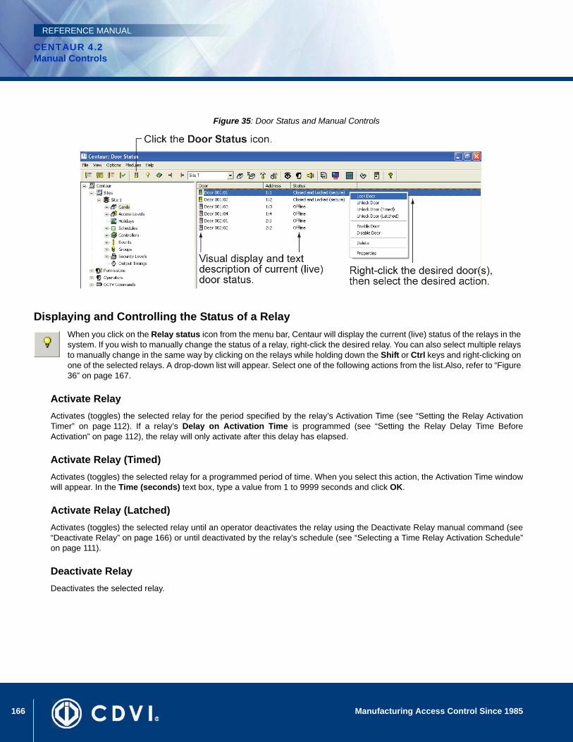
166 Manufacturing Access Control Since 1985
CENTAUR 4.2Manual Controls
REFERENCE MANUAL
Figure 35: Door Status and Manual Controls
Displaying and Controlling the Status of a RelayWhen you click on the Relay status icon from the menu bar, Centaur will display the current (live) status of the relays in the system. If you wish to manually change the status of a relay, right-click the desired relay. You can also select multiple relays to manually change in the same way by clicking on the relays while holding down the Shift or Ctrl keys and right-clicking on one of the selected relays. A drop-down list will appear. Select one of the following actions from the list.Also, refer to “Figure 36” on page 167.
Activate RelayActivates (toggles) the selected relay for the period specified by the relay’s Activation Time (see “Setting the Relay ActivationTimer” on page 112). If a relay’s Delay on Activation Time is programmed (see “Setting the Relay Delay Time BeforeActivation” on page 112), the relay will only activate after this delay has elapsed.
Activate Relay (Timed)Activates (toggles) the selected relay for a programmed period of time. When you select this action, the Activation Time windowwill appear. In the Time (seconds) text box, type a value from 1 to 9999 seconds and click OK.
Activate Relay (Latched)Activates (toggles) the selected relay until an operator deactivates the relay using the Deactivate Relay manual command (see“Deactivate Relay” on page 166) or until deactivated by the relay’s schedule (see “Selecting a Time Relay Activation Schedule”on page 111).
Deactivate RelayDeactivates the selected relay.
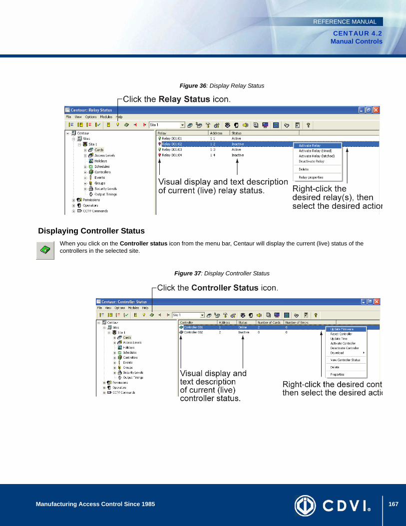
167Manufacturing Access Control Since 1985
CENTAUR 4.2Manual Controls
REFERENCE MANUAL
Figure 36: Display Relay Status
Displaying Controller StatusWhen you click on the Controller status icon from the menu bar, Centaur will display the current (live) status of the controllers in the selected site.
Figure 37: Display Controller Status
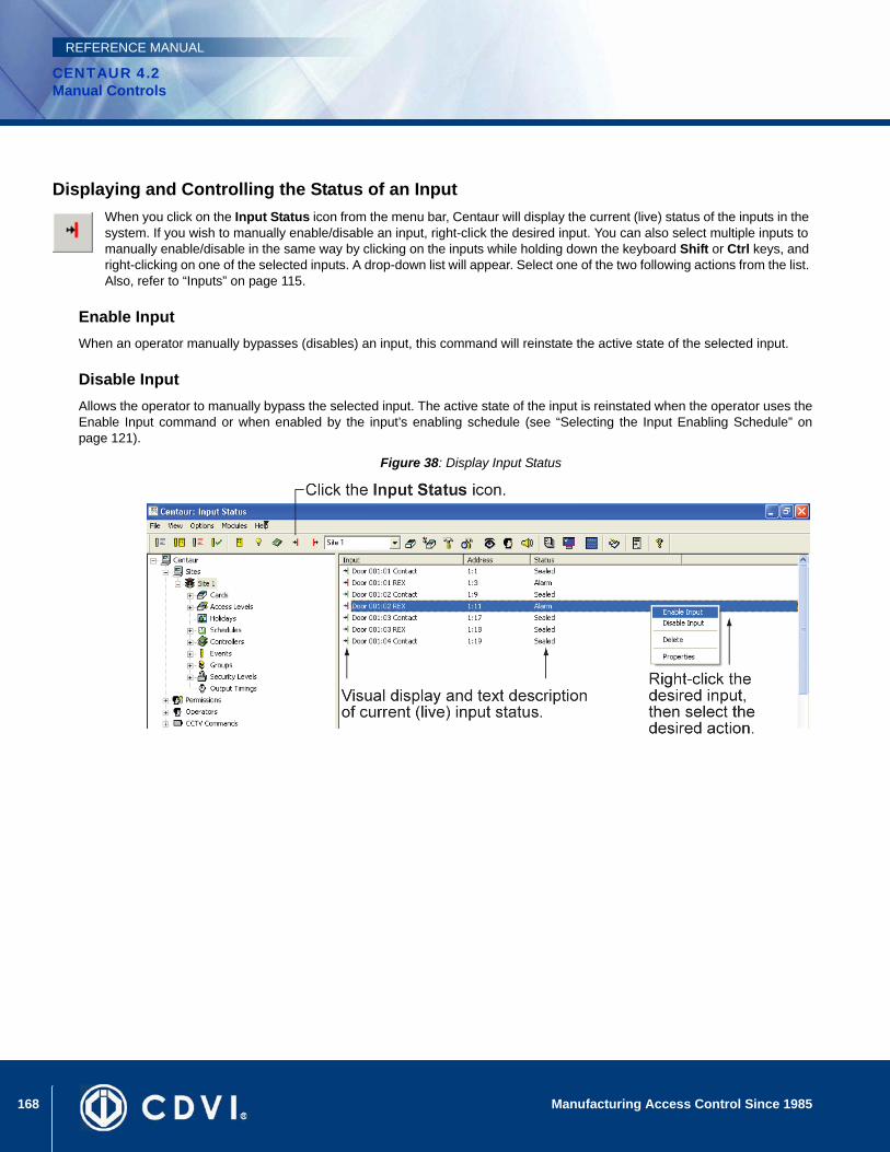
168 Manufacturing Access Control Since 1985
CENTAUR 4.2Manual Controls
REFERENCE MANUAL
Displaying and Controlling the Status of an Input When you click on the Input Status icon from the menu bar, Centaur will display the current (live) status of the inputs in the system. If you wish to manually enable/disable an input, right-click the desired input. You can also select multiple inputs to manually enable/disable in the same way by clicking on the inputs while holding down the keyboard Shift or Ctrl keys, and right-clicking on one of the selected inputs. A drop-down list will appear. Select one of the two following actions from the list. Also, refer to “Inputs” on page 115.
Enable InputWhen an operator manually bypasses (disables) an input, this command will reinstate the active state of the selected input.
Disable InputAllows the operator to manually bypass the selected input. The active state of the input is reinstated when the operator uses theEnable Input command or when enabled by the input’s enabling schedule (see “Selecting the Input Enabling Schedule” onpage 121).
Figure 38: Display Input Status
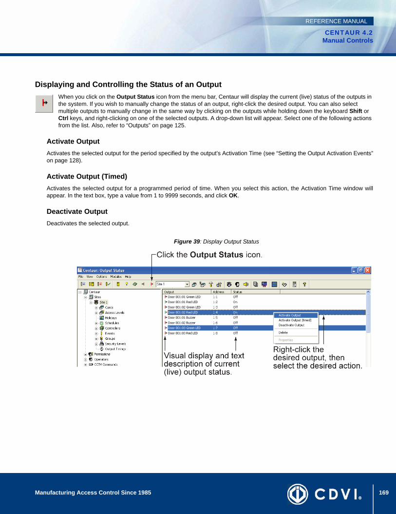
169Manufacturing Access Control Since 1985
CENTAUR 4.2Manual Controls
REFERENCE MANUAL
Displaying and Controlling the Status of an Output When you click on the Output Status icon from the menu bar, Centaur will display the current (live) status of the outputs in the system. If you wish to manually change the status of an output, right-click the desired output. You can also select multiple outputs to manually change in the same way by clicking on the outputs while holding down the keyboard Shift or Ctrl keys, and right-clicking on one of the selected outputs. A drop-down list will appear. Select one of the following actions from the list. Also, refer to “Outputs” on page 125.
Activate OutputActivates the selected output for the period specified by the output’s Activation Time (see “Setting the Output Activation Events”on page 128).
Activate Output (Timed)Activates the selected output for a programmed period of time. When you select this action, the Activation Time window willappear. In the text box, type a value from 1 to 9999 seconds, and click OK.
Deactivate OutputDeactivates the selected output.
Figure 39: Display Output Status

170 Manufacturing Access Control Since 1985
CENTAUR 4.2Manual Controls
REFERENCE MANUAL
171
CENTAUR 4.2Access Control Software
Manufacturing Access Control Since 1985
REFERENCE MANUAL
Chapter 20: Database Management
What Will I Find?What are the Centaur Databases? . . . . . . . . . . . . . . . . . . . . . . . . . . . . . . . . . . . . . . . . . . . . . . . . . . . . . . . . . . . . . . . . . . . . . . . . . 172Database Management Module. . . . . . . . . . . . . . . . . . . . . . . . . . . . . . . . . . . . . . . . . . . . . . . . . . . . . . . . . . . . . . . . . . . . . . . . . . . . 172Database Backup Scheduler . . . . . . . . . . . . . . . . . . . . . . . . . . . . . . . . . . . . . . . . . . . . . . . . . . . . . . . . . . . . . . . . . . . . . . . . . . . . . . 178
Centaur’s database file management feature is automatically installed with Centaur Server. This database utility was designed to control and manage the often large and complex database files of the Centaur software. You can back up and restore database files, purge events from selected sites during specific periods, limit the size of database files and delete entire database files.
172 Manufacturing Access Control Since 1985
CENTAUR 4.2Database Management
REFERENCE MANUAL
What are the Centaur Databases?Before starting, you need to understand how the Centaur databases are used and what information is saved in them. These databases are attached to the SQL Server application used by Centaur. Whenever something is programmed or an event occurs in the system, the information is downloaded to the SQL Server and saved in the Main and/or Event databases. These files are saved on your hard drive in the following default path C:\Program Files\CDV Americas\Centaur\Centaur Server\Data. Only databases currently used by SQL and Centaur will be saved in the above-mentioned directory path. The backup files can be saved wherever you wish.
Main DatabaseThe Main database (CentaurMain) contains all the system characteristics of the Centaur software (i.e. sites, controllers, schedules, cards, etc.). The more sites, cards and controllers you have programmed, the bigger this file will be.
Event DatabaseThe Event database (CentaurEvents) contains all events that have occurred in the system (i.e. “Access Granted”, “Door Forced”, alarms, etc.). For more information on how you can manage the size of the Event database, please refer to “Limiting the Event Database’s Size” on page 174. Also, refer to “Disk” on page 135.
Database Management ModuleThe Centaur Database Management Module is automatically installed with Centaur and can only be run on the Server. This database utility was designed to control and manage the often large and complex database files of the Centaur software. You can back up and restore database files, purge events from selected sites during specific periods, limit the size of database files and delete entire database files.
Starting the Database Management ModuleThe Database Management Module can be started using one of two methods. To start the module from within Centaur, click the Open Database Management Module icon from the main menu bar. If you open the Database Management Module from within Centaur, the Restore, Attach, Detach, and Remove database options will not be available. To access all database options, run the Database Management Module as described below.
1. Make sure the SQL Server is running and that the Centaur Administration Console isn’t running and the Centaur Service Manager is stopped and exit (refer to “Starting the Centaur Server and Software” on page 11).
2. Click Start, point to Programs, CDV Americas, Centaur, and click Centaur Database Manager.
3. From the SPXDBase Logon window, type the appropriate Logon ID and Password. Centaur’s database file management utility uses the same Logon ID and Password as Centaur.
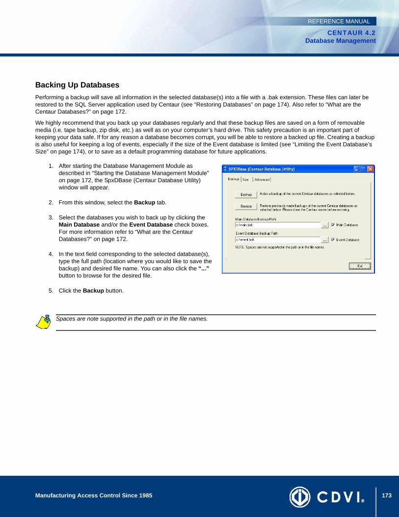
173Manufacturing Access Control Since 1985
CENTAUR 4.2Database Management
REFERENCE MANUAL
Backing Up DatabasesPerforming a backup will save all information in the selected database(s) into a file with a .bak extension. These files can later be restored to the SQL Server application used by Centaur (see “Restoring Databases” on page 174). Also refer to “What are the Centaur Databases?” on page 172.
We highly recommend that you back up your databases regularly and that these backup files are saved on a form of removable media (i.e. tape backup, zip disk, etc.) as well as on your computer’s hard drive. This safety precaution is an important part of keeping your data safe. If for any reason a database becomes corrupt, you will be able to restore a backed up file. Creating a backup is also useful for keeping a log of events, especially if the size of the Event database is limited (see “Limiting the Event Database’s Size” on page 174), or to save as a default programming database for future applications.
1. After starting the Database Management Module as described in “Starting the Database Management Module” on page 172, the SpxDBase (Centaur Database Utility) window will appear.
2. From this window, select the Backup tab.
3. Select the databases you wish to back up by clicking the Main Database and/or the Event Database check boxes. For more information refer to “What are the Centaur Databases?” on page 172.
4. In the text field corresponding to the selected database(s), type the full path (location where you would like to save the backup) and desired file name. You can also click the “...” button to browse for the desired file.
5. Click the Backup button.
Spaces are note supported in the path or in the file names.

174 Manufacturing Access Control Since 1985
CENTAUR 4.2Database Management
REFERENCE MANUAL
Restoring Databases Restoring databases will bring back all information saved in a backed up database file (.bak) so it can be used with the Centaur software. Performing a restoration will attach the back up files to the SQL Server application and save them in C:\Program Files\CDV Americas\Centaur\Centaur Server\Data. This will overwrite any databases currently attached.
If you are having problems with a database, or if you have experienced a loss of data, or if your database is corrupted due to a computer hardware failure, you can restore any database that you have backed up. Please note that you will have to add any programming changes that were done since the last backup was created. If events are also restored, all events that have occurred since the last backup will be lost.
1. After starting the Database Management Module as described in “Starting the Database Management Module” on page 172, the SpxDBase (Centaur Database Utility) window will appear.
2. From this window, select the Backup tab.
3. Select the databases you wish to restore by clicking the Main Database and/or the Event Database check boxes. For more information refer to “What are the Centaur Databases?” on page 172.
4. In the text field corresponding to the selected database(s), type the full path and the name of the file from which you want to restore the database. You can also click the “...” button to browse for the desired file.
5. Click the Restore button.
Limiting the Event Database’s SizeWith this feature, you can define the maximum size of the Event database. This feature will not affect the Main database, only the Event database (see “What are the Centaur Databases?” on page 172). When the Event database has reached its maximum size, each subsequent event will be followed by a “Failed to Process Event” event, which will appear in the Real-Time Events/Status window. At this point, events will not be saved because the database has exceeded its maximum size. You should perform a backup of the Event database (see “Backing Up Databases” on page 173), and then truncate (see “Truncating Events” on page 175) the database to reduce its size. Perform the following to define the size of the Event database:
1. After starting the Database Management Module as described in “Starting the Database Management Module” on page 172, the SpxDBase (Centaur Database Utility) window will appear.
2. From this window, select the Size tab and click the Size button.
3. In the Restrict growth of Event database to text field, type the maximum size of the Event database in MB, or select the Unlimited Growth check box. If using MSDE, growth is limited to 2GB.
4. Click OK.
Do not select the Unlimited Growth check box unless the full version of SQL server is installed. Do not enter more than 1800MB when using MSDE.
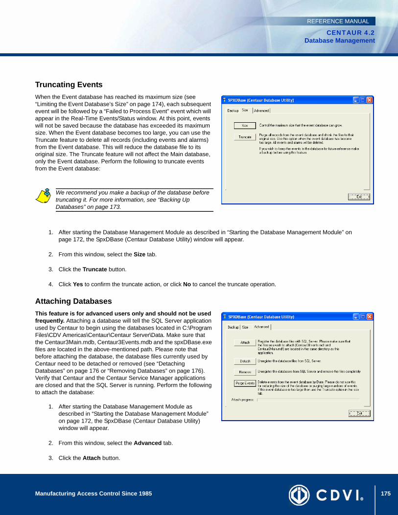
175Manufacturing Access Control Since 1985
CENTAUR 4.2Database Management
REFERENCE MANUAL
Truncating EventsWhen the Event database has reached its maximum size (see “Limiting the Event Database’s Size” on page 174), each subsequent event will be followed by a “Failed to Process Event” event which will appear in the Real-Time Events/Status window. At this point, events will not be saved because the database has exceeded its maximum size. When the Event database becomes too large, you can use the Truncate feature to delete all records (including events and alarms) from the Event database. This will reduce the database file to its original size. The Truncate feature will not affect the Main database, only the Event database. Perform the following to truncate events from the Event database:
1. After starting the Database Management Module as described in “Starting the Database Management Module” on page 172, the SpxDBase (Centaur Database Utility) window will appear.
2. From this window, select the Size tab.
3. Click the Truncate button.
4. Click Yes to confirm the truncate action, or click No to cancel the truncate operation.
Attaching DatabasesThis feature is for advanced users only and should not be used frequently. Attaching a database will tell the SQL Server application used by Centaur to begin using the databases located in C:\Program Files\CDV Americas\Centaur\Centaur Server\Data. Make sure that the Centaur3Main.mdb, Centaur3Events.mdb and the spxDBase.exe files are located in the above-mentioned path. Please note that before attaching the database, the database files currently used by Centaur need to be detached or removed (see “Detaching Databases” on page 176 or “Removing Databases” on page 176). Verify that Centaur and the Centaur Service Manager applications are closed and that the SQL Server is running. Perform the following to attach the database:
1. After starting the Database Management Module as described in “Starting the Database Management Module” on page 172, the SpxDBase (Centaur Database Utility) window will appear.
2. From this window, select the Advanced tab.
3. Click the Attach button.
We recommend you make a backup of the database before truncating it. For more information, see “Backing Up Databases” on page 173.
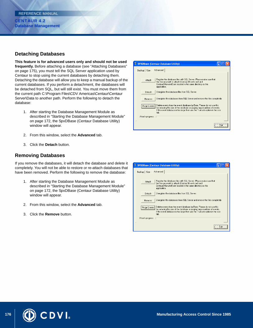
176 Manufacturing Access Control Since 1985
CENTAUR 4.2Database Management
REFERENCE MANUAL
Detaching DatabasesThis feature is for advanced users only and should not be used frequently. Before attaching a database (see “Attaching Databases” on page 175), you must tell the SQL Server application used by Centaur to stop using the current databases by detaching them. Detaching the database will allow you to keep a manual backup of the current databases. If you perform a detachment, the databases will be detached from SQL, but will still exist. You must move them from the current path C:\Program Files\CDV Americas\Centaur\Centaur Server\Data to another path. Perform the following to detach the database:
1. After starting the Database Management Module as described in “Starting the Database Management Module” on page 172, the SpxDBase (Centaur Database Utility) window will appear.
2. From this window, select the Advanced tab.
3. Click the Detach button.
Removing DatabasesIf you remove the databases, it will detach the database and delete it completely. You will not be able to restore or re-attach databases that have been removed. Perform the following to remove the database:
1. After starting the Database Management Module as described in “Starting the Database Management Module” on page 172, the SpxDBase (Centaur Database Utility) window will appear.
2. From this window, select the Advanced tab.
3. Click the Remove button.
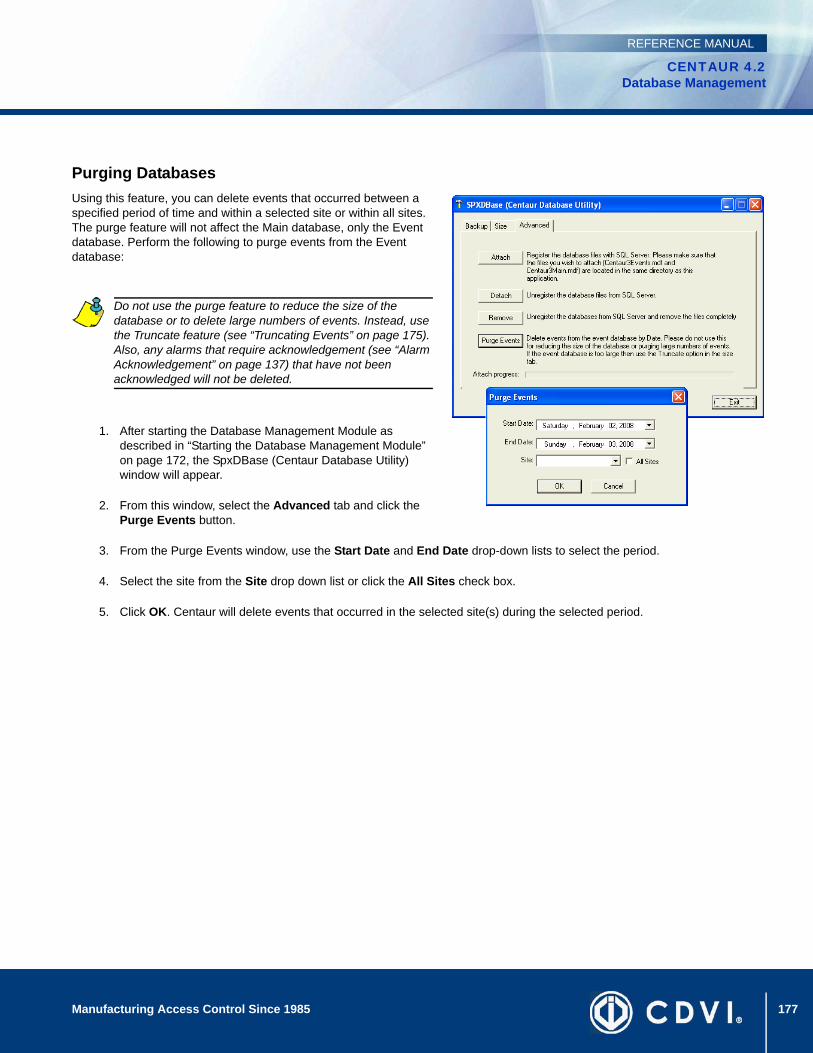
177Manufacturing Access Control Since 1985
CENTAUR 4.2Database Management
REFERENCE MANUAL
Purging DatabasesUsing this feature, you can delete events that occurred between a specified period of time and within a selected site or within all sites. The purge feature will not affect the Main database, only the Event database. Perform the following to purge events from the Event database:
1. After starting the Database Management Module as described in “Starting the Database Management Module” on page 172, the SpxDBase (Centaur Database Utility) window will appear.
2. From this window, select the Advanced tab and click the Purge Events button.
3. From the Purge Events window, use the Start Date and End Date drop-down lists to select the period.
4. Select the site from the Site drop down list or click the All Sites check box.
5. Click OK. Centaur will delete events that occurred in the selected site(s) during the selected period.
Do not use the purge feature to reduce the size of the database or to delete large numbers of events. Instead, use the Truncate feature (see “Truncating Events” on page 175). Also, any alarms that require acknowledgement (see “Alarm Acknowledgement” on page 137) that have not been acknowledged will not be deleted.
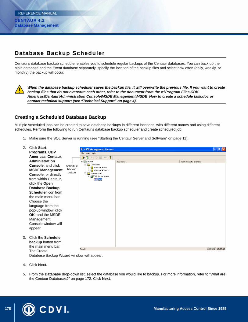
178 Manufacturing Access Control Since 1985
CENTAUR 4.2Database Management
REFERENCE MANUAL
Database Backup SchedulerCentaur’s database backup scheduler enables you to schedule regular backups of the Centaur databases. You can back up the Main database and the Event database separately, specify the location of the backup files and select how often (daily, weekly, or monthly) the backup will occur.
Creating a Scheduled Database BackupMultiple scheduled jobs can be created to save database backups in different locations, with different names and using different schedules. Perform the following to run Centaur’s database backup scheduler and create scheduled job:
1. Make sure the SQL Server is running (see “Starting the Centaur Server and Software” on page 11).
2. Click Start, Programs, CDV Americas, Centaur, Administration Console, and click MSDE Management Console, or directly from within Centaur, click the Open Database Backup Scheduler icon from the main menu bar. Choose the language from the pop-up window, click OK, and the MSDE Management Console window will appear.
3. Click the Schedule backup button from the main menu bar. The Create Database Backup Wizard window will appear.
4. Click Next.
5. From the Database drop-down list, select the database you would like to backup. For more information, refer to “What are the Centaur Databases?” on page 172. Click Next.
When the database backup scheduler saves the backup file, it will overwrite the previous file. If you want to create backup files that do not overwrite each other, refer to the document from the c:\Program Files\CDV Americas\Centaur\Administration Console\MSDE Management\MSDE_How to create a schedule task.doc or contact technical support (see “Technical Support” on page 4).
Schedule backup button
179Manufacturing Access Control Since 1985
CENTAUR 4.2Database Management
REFERENCE MANUAL
6. In the Name text box, type the job name of the scheduled backup. In the Description text box, type the description of the backup. Click Next.
7. In the Select backup file text field, type the full path (location where you would like to save the backup) and the desired file name. You can also click the “...” button to browse for the desired path and/or file. Click Next.
8. Select Create a scheduled job to be performed periodically. A text field will appear indicating the current schedule. Click the Change button to change the schedule and click OK. After changing the schedule, and click Next.
9. Click Finish.
Editing a Scheduled Database BackupYou cannot edit a scheduled job. If you need to change the scheduled job’s settings, you must delete the existing job (see “Deleting a Scheduled Database Backup” on page 179) and then re-create a new one (see “Creating a Scheduled Database Backup” on page 178).
Deleting a Scheduled Database BackupPerform the following to delete a scheduled job:
1. Make sure the SQL Server is running (see “Starting the Centaur Server and Software” on page 11).
2. Click Start, Programs, CDV Americas, Centaur, and click MSDE Management Console, or directly from within Centaur, click the Open Database Backup Scheduler icon from the main menu bar. The MSDE Management Console window will appear.
3. From the Database Tree View window (left-hand portion of your screen), double-click the Jobs branch.
4. From the Details window (right-hand portion of your screen), right-click the desired job and click Delete job. A dialogue box will appear requesting confirmation.

180 Manufacturing Access Control Since 1985
CENTAUR 4.2Database Management
REFERENCE MANUAL

181
CENTAUR 4.2Access Control Software
Manufacturing Access Control Since 1985
REFERENCE MANUAL
Chapter 21: Centaur Wave Player
What Will I Find?Starting Centaur Wave Player . . . . . . . . . . . . . . . . . . . . . . . . . . . . . . . . . . . . . . . . . . . . . . . . . . . . . . . . . . . . . . . . . . . . . . . . . . . . . 182Assigning a WAV File. . . . . . . . . . . . . . . . . . . . . . . . . . . . . . . . . . . . . . . . . . . . . . . . . . . . . . . . . . . . . . . . . . . . . . . . . . . . . . . . . . . . 182
This utility was designed to enable a .wav file to be played on the computer when an event that requires acknowledgement occurs. The sound can replay at programmed intervals until the alarm is acknowledged.
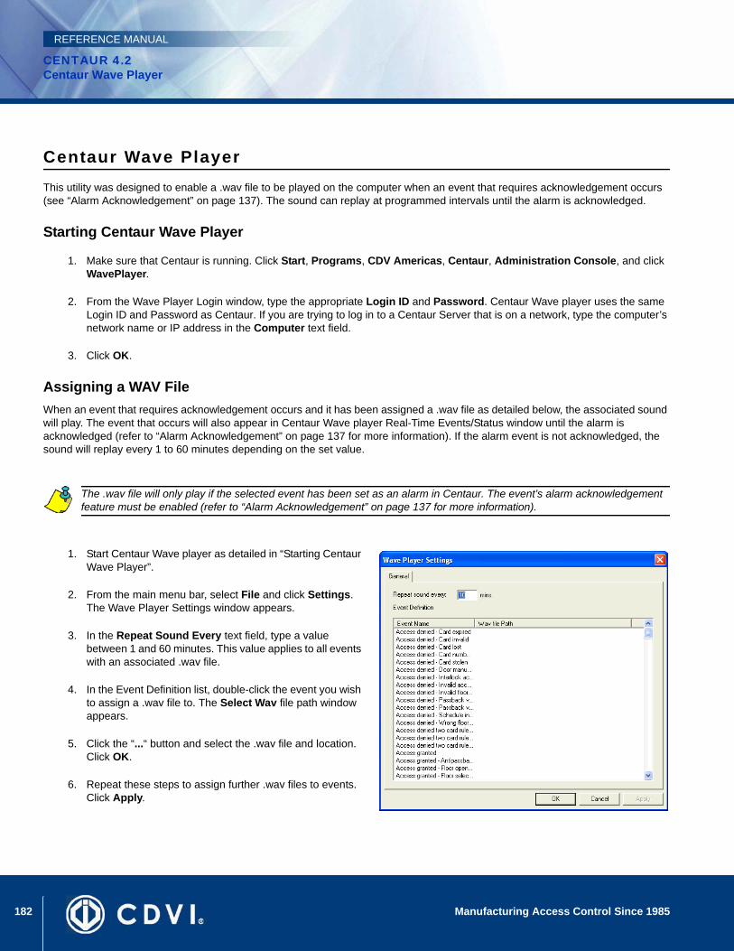
182 Manufacturing Access Control Since 1985
CENTAUR 4.2Centaur Wave Player
REFERENCE MANUAL
Centaur Wave PlayerThis utility was designed to enable a .wav file to be played on the computer when an event that requires acknowledgement occurs (see “Alarm Acknowledgement” on page 137). The sound can replay at programmed intervals until the alarm is acknowledged.
Starting Centaur Wave Player
1. Make sure that Centaur is running. Click Start, Programs, CDV Americas, Centaur, Administration Console, and click WavePlayer.
2. From the Wave Player Login window, type the appropriate Login ID and Password. Centaur Wave player uses the same Login ID and Password as Centaur. If you are trying to log in to a Centaur Server that is on a network, type the computer’s network name or IP address in the Computer text field.
3. Click OK.
Assigning a WAV File When an event that requires acknowledgement occurs and it has been assigned a .wav file as detailed below, the associated sound will play. The event that occurs will also appear in Centaur Wave player Real-Time Events/Status window until the alarm is acknowledged (refer to “Alarm Acknowledgement” on page 137 for more information). If the alarm event is not acknowledged, the sound will replay every 1 to 60 minutes depending on the set value.
1. Start Centaur Wave player as detailed in “Starting Centaur Wave Player”.
2. From the main menu bar, select File and click Settings. The Wave Player Settings window appears.
3. In the Repeat Sound Every text field, type a value between 1 and 60 minutes. This value applies to all events with an associated .wav file.
4. In the Event Definition list, double-click the event you wish to assign a .wav file to. The Select Wav file path window appears.
5. Click the “...“ button and select the .wav file and location. Click OK.
6. Repeat these steps to assign further .wav files to events. Click Apply.
The .wav file will only play if the selected event has been set as an alarm in Centaur. The event’s alarm acknowledgement feature must be enabled (refer to “Alarm Acknowledgement” on page 137 for more information).

183
CENTAUR 4.2Access Control Software
Manufacturing Access Control Since 1985
REFERENCE MANUAL
Appendix A: DCOM Configuration
What Will I Find?DCOM Configuration for Windows XP. . . . . . . . . . . . . . . . . . . . . . . . . . . . . . . . . . . . . . . . . . . . . . . . . . . . . . . . . . . . . . . . . . . . . . . 184DCOM Configuration for Windows 2003 Server . . . . . . . . . . . . . . . . . . . . . . . . . . . . . . . . . . . . . . . . . . . . . . . . . . . . . . . . . . . . . . . 206DCOM Configuration for Windows 2000 Pro and Server. . . . . . . . . . . . . . . . . . . . . . . . . . . . . . . . . . . . . . . . . . . . . . . . . . . . . . . . . 235
Centaur uses Distributed Component Object Model (DCOM) to communicate between its software components. DCOM is a protocol that enables software components to communicate directly across multiple network transports, including Internet protocols such as HTTP, in a reliable, secure, and efficient manner.
It is necessary to configure the DCOM only when operators need to access the Centaur Server computer from remote computers. DCOM configuration is performed on the Centaur Server computer only and sets Windows to allow access from remote workstations creating Windows user accounts.
Before configuring the DCOM, the Centaur Server must be installed (refer to “Installation Overview” on page 3) and the users that will access the Centaur Server must be programmed in the server. The DCOM Configuration Utility is automatically installed with Windows 2000/2003/XP operating systems. We recommend this settings to be done by a network administrator.
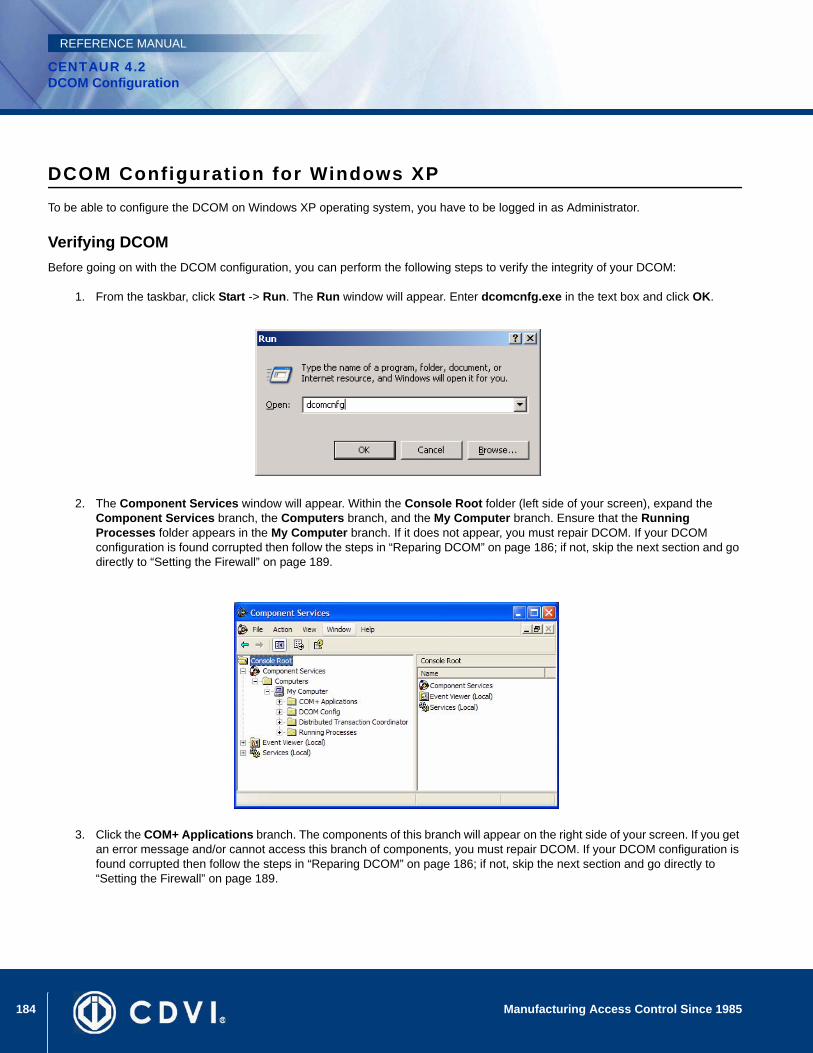
184 Manufacturing Access Control Since 1985
CENTAUR 4.2DCOM Configuration
REFERENCE MANUAL
DCOM Configuration for Windows XPTo be able to configure the DCOM on Windows XP operating system, you have to be logged in as Administrator.
Verifying DCOMBefore going on with the DCOM configuration, you can perform the following steps to verify the integrity of your DCOM:
1. From the taskbar, click Start -> Run. The Run window will appear. Enter dcomcnfg.exe in the text box and click OK.
2. The Component Services window will appear. Within the Console Root folder (left side of your screen), expand the Component Services branch, the Computers branch, and the My Computer branch. Ensure that the Running Processes folder appears in the My Computer branch. If it does not appear, you must repair DCOM. If your DCOM configuration is found corrupted then follow the steps in “Reparing DCOM” on page 186; if not, skip the next section and go directly to “Setting the Firewall” on page 189.
3. Click the COM+ Applications branch. The components of this branch will appear on the right side of your screen. If you get an error message and/or cannot access this branch of components, you must repair DCOM. If your DCOM configuration is found corrupted then follow the steps in “Reparing DCOM” on page 186; if not, skip the next section and go directly to “Setting the Firewall” on page 189.
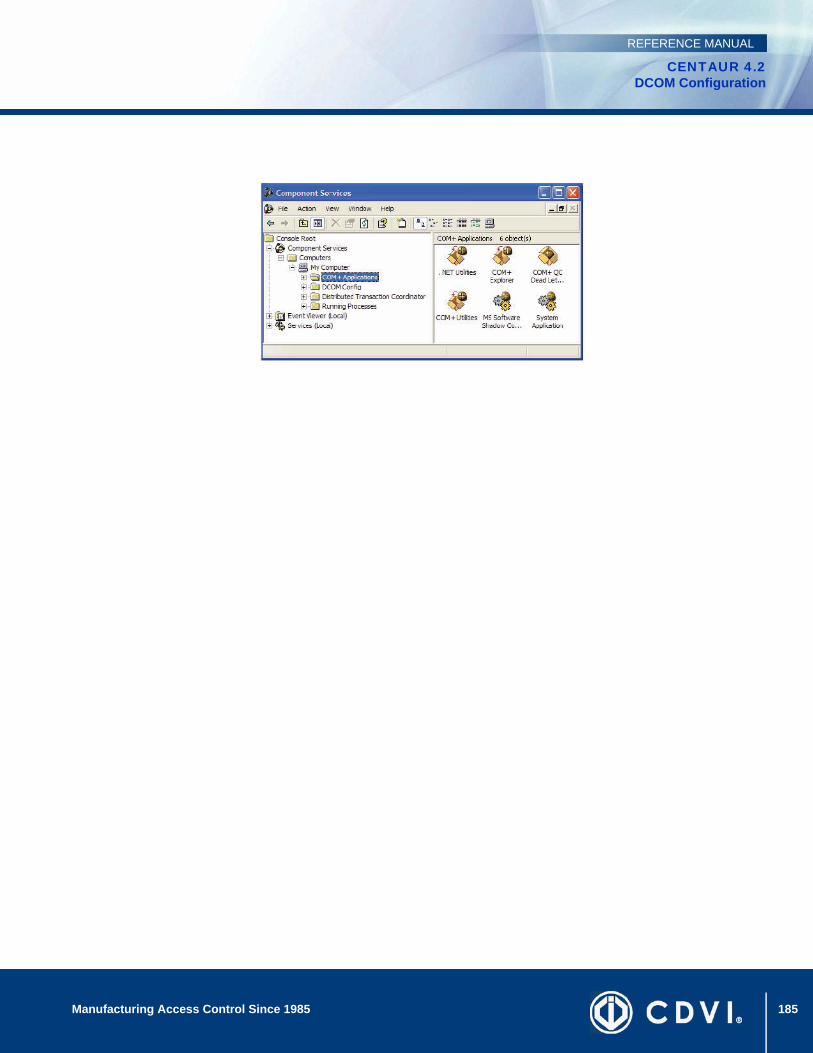
185Manufacturing Access Control Since 1985
CENTAUR 4.2DCOM Configuration
REFERENCE MANUAL
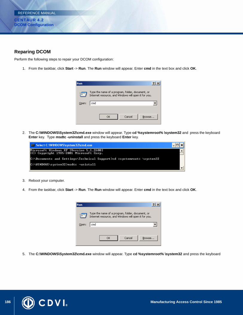
186 Manufacturing Access Control Since 1985
CENTAUR 4.2DCOM Configuration
REFERENCE MANUAL
Reparing DCOMPerform the following steps to repair your DCOM configuration:
1. From the taskbar, click Start -> Run. The Run window will appear. Enter cmd in the text box and click OK.
2. The C:\WINDOWS\System32\cmd.exe window will appear. Type cd %systemroot% \system32 and press the keyboard Enter key. Type msdtc -uninstall and press the keyboard Enter key.
3. Reboot your computer.
4. From the taskbar, click Start -> Run. The Run window will appear. Enter cmd in the text box and click OK.
5. The C:\WINDOWS\System32\cmd.exe window will appear. Type cd %systemroot% \system32 and press the keyboard
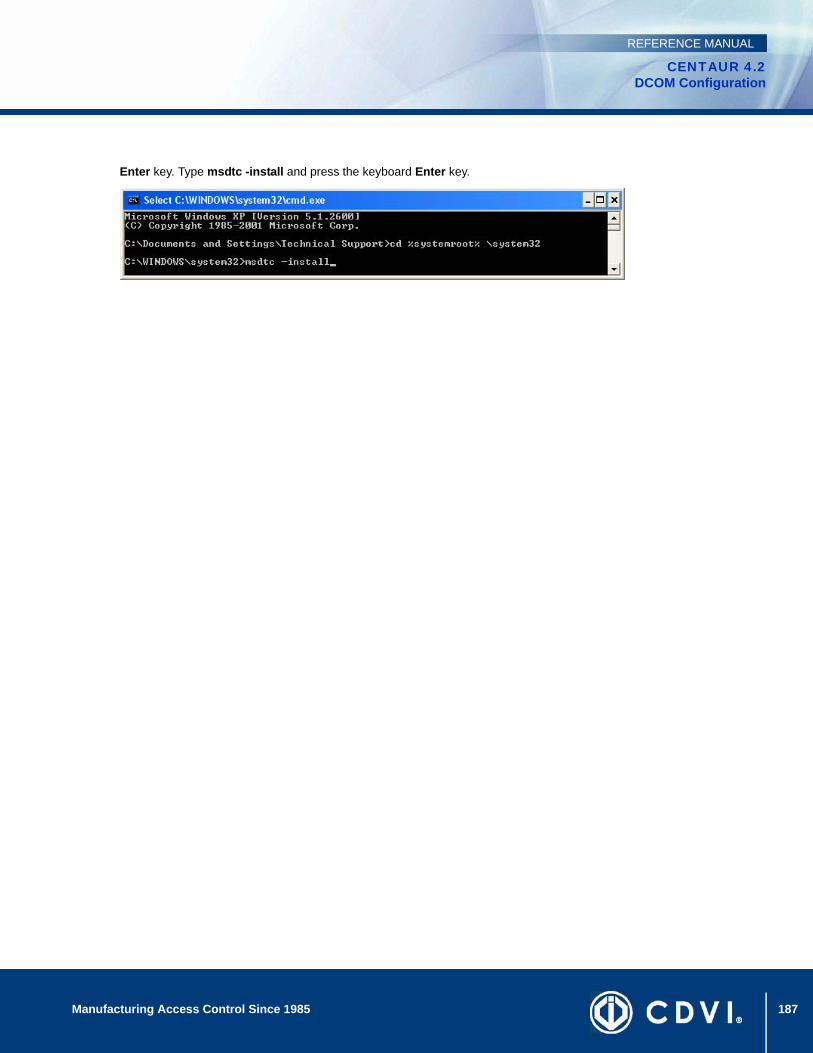
187Manufacturing Access Control Since 1985
CENTAUR 4.2DCOM Configuration
REFERENCE MANUAL
Enter key. Type msdtc -install and press the keyboard Enter key.

188 Manufacturing Access Control Since 1985
CENTAUR 4.2DCOM Configuration
REFERENCE MANUAL
Verifying if the DCOM has been repairedPerform the following steps to verify that DCOM has been repaired:
1. From the taskbar, click Start -> Run. The Run window will appear. Enter dcomcnfg.exe in the text box and click OK.
The Component Services window will appear. In the Console Root folder (left side of your screen), expand the Component Services branch, the Computers branch, and the My Computer branch. If there is a red arrow next to any of the components of this folder, DCOM has not been successfully repaired and you must repeat the repairing process.
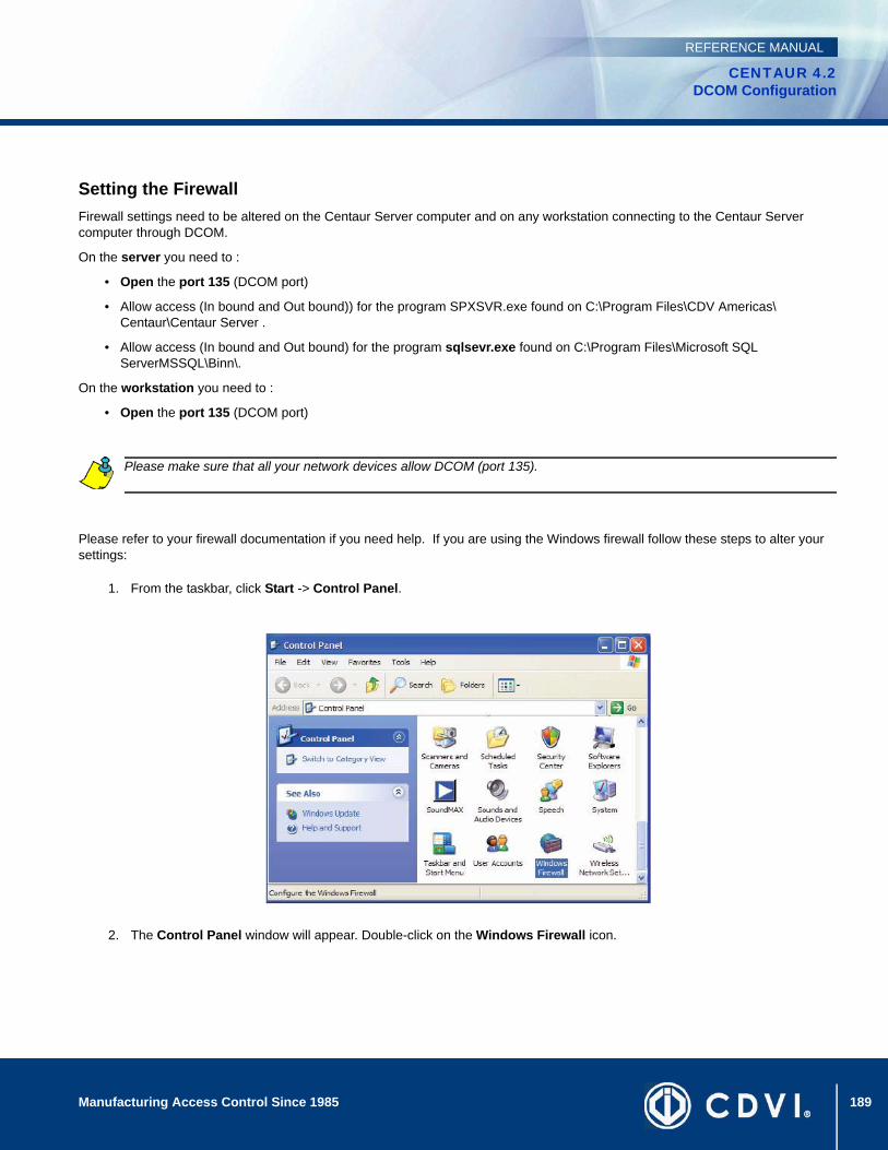
189Manufacturing Access Control Since 1985
CENTAUR 4.2DCOM Configuration
REFERENCE MANUAL
Setting the FirewallFirewall settings need to be altered on the Centaur Server computer and on any workstation connecting to the Centaur Server computer through DCOM.
On the server you need to :
• Open the port 135 (DCOM port)
• Allow access (In bound and Out bound)) for the program SPXSVR.exe found on C:\Program Files\CDV Americas\ Centaur\Centaur Server .
• Allow access (In bound and Out bound) for the program sqlsevr.exe found on C:\Program Files\Microsoft SQL ServerMSSQL\Binn\.
On the workstation you need to :
• Open the port 135 (DCOM port)
Please refer to your firewall documentation if you need help. If you are using the Windows firewall follow these steps to alter your settings:
1. From the taskbar, click Start -> Control Panel.
2. The Control Panel window will appear. Double-click on the Windows Firewall icon.
Please make sure that all your network devices allow DCOM (port 135).

190 Manufacturing Access Control Since 1985
CENTAUR 4.2DCOM Configuration
REFERENCE MANUAL
The Windows Firewall window will appear. From the Exceptions tab, click Add Port.
The Add a Port window will appear. In the Name field, enter DCOM. In the Port number field, enter 135. Select TCP as your communication type and click OK.
3. The Windows Firewall window will re-appear. From the Exceptions tab, make sure that the DCOM check box below the Programs and Services heading is selected.
If you are configuring the firewall settings on a workstation connected to the Centaur Server computer, click OK and your done with this computer.
If you are configuring your firewall settings on the Centaur Server computer, go to the next step.

191Manufacturing Access Control Since 1985
CENTAUR 4.2DCOM Configuration
REFERENCE MANUAL
4. From the Exceptions tab, click Add Program.
5. The Add a Program window will appear. Click Browse... and select the spxsvr.exe file (located by default in C:\Program Files\CDV Americas\Centaur\Centaur Server) and click OK.
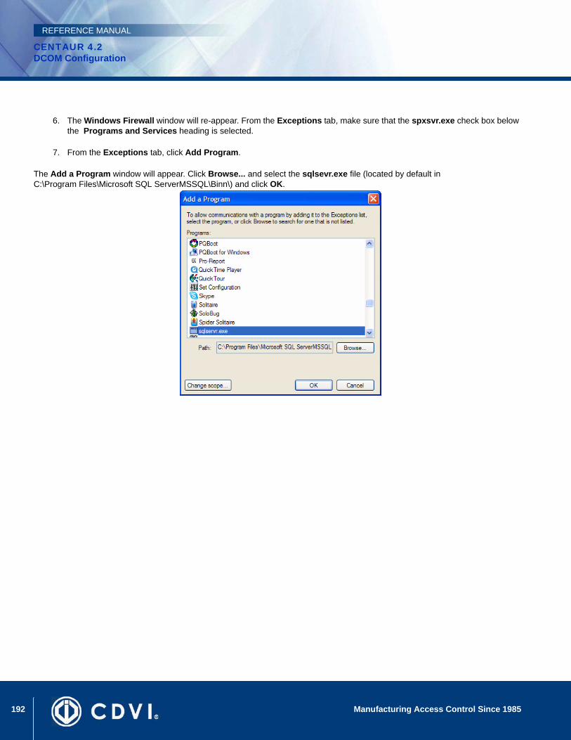
192 Manufacturing Access Control Since 1985
CENTAUR 4.2DCOM Configuration
REFERENCE MANUAL
6. The Windows Firewall window will re-appear. From the Exceptions tab, make sure that the spxsvr.exe check box below the Programs and Services heading is selected.
7. From the Exceptions tab, click Add Program.
The Add a Program window will appear. Click Browse... and select the sqlsevr.exe file (located by default in C:\Program Files\Microsoft SQL ServerMSSQL\Binn\) and click OK.
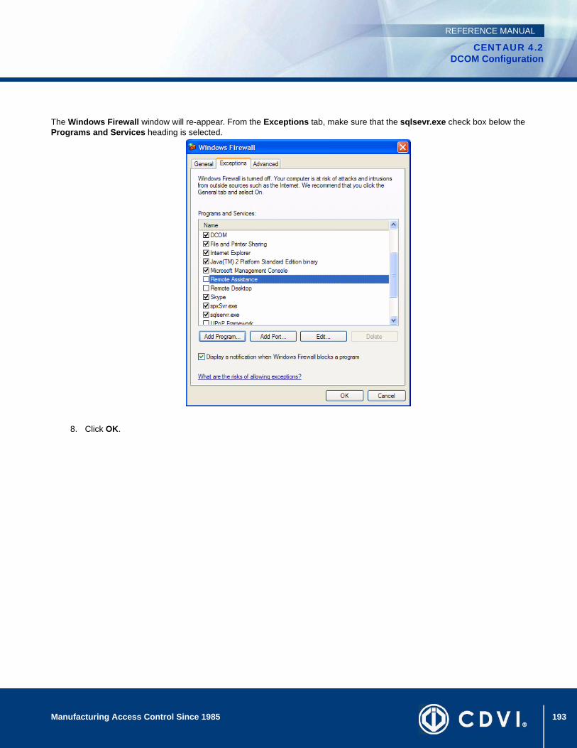
193Manufacturing Access Control Since 1985
CENTAUR 4.2DCOM Configuration
REFERENCE MANUAL
The Windows Firewall window will re-appear. From the Exceptions tab, make sure that the sqlsevr.exe check box below the Programs and Services heading is selected.
8. Click OK.
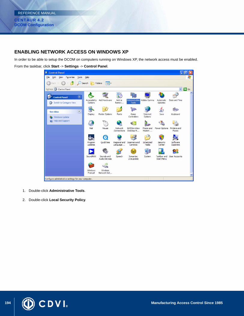
194 Manufacturing Access Control Since 1985
CENTAUR 4.2DCOM Configuration
REFERENCE MANUAL
ENABLING NETWORK ACCESS ON WINDOWS XPIn order to be able to setup the DCOM on computers running on Windows XP, the network access must be enabled.
From the taskbar, click Start -> Settings -> Control Panel.
1. Double-click Administrative Tools.
2. Double-click Local Security Policy.
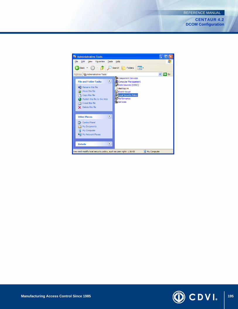
195Manufacturing Access Control Since 1985
CENTAUR 4.2DCOM Configuration
REFERENCE MANUAL
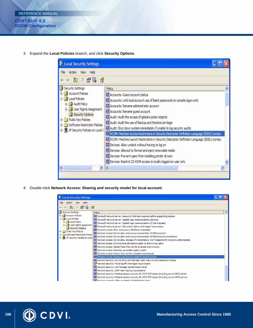
196 Manufacturing Access Control Since 1985
CENTAUR 4.2DCOM Configuration
REFERENCE MANUAL
3. Expand the Local Policies branch, and click Security Options.
4. Double-click Network Access: Sharing and security model for local account.
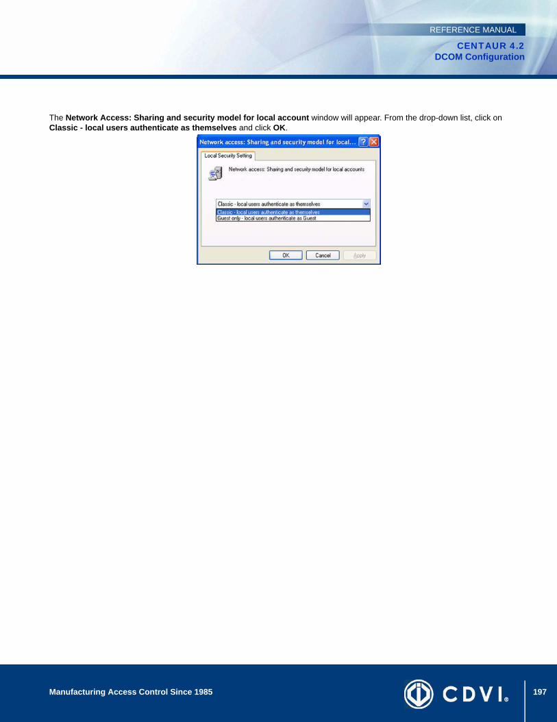
197Manufacturing Access Control Since 1985
CENTAUR 4.2DCOM Configuration
REFERENCE MANUAL
The Network Access: Sharing and security model for local account window will appear. From the drop-down list, click on Classic - local users authenticate as themselves and click OK.
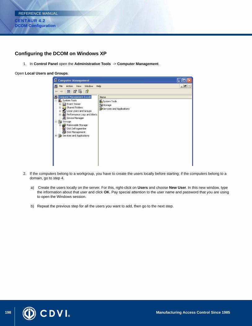
198 Manufacturing Access Control Since 1985
CENTAUR 4.2DCOM Configuration
REFERENCE MANUAL
Configuring the DCOM on Windows XP
1. In Control Panel open the Administrative Tools -> Computer Management.
Open Local Users and Groups.
2. If the computers belong to a workgroup, you have to create the users locally before starting; if the computers belong to a domain, go to step 4.
a) Create the users locally on the server. For this, right-click on Users and choose New User. In this new window, type the information about that user and click OK. Pay special attention to the user name and password that you are using to open the Windows session.
b) Repeat the previous step for all the users you want to add, then go to the next step.

199Manufacturing Access Control Since 1985
CENTAUR 4.2DCOM Configuration
REFERENCE MANUAL
To create the group to be used for DCOM you have to click on the Groups and select New Group.
3. In the field Name type Centaur Group. Click on the Add… button to add the users that you want to have access to the Centaur Server.
4. The window Select Users, Computers or Groups pops-up. Click on the Advanced … button and check if the Object Types … and Locations … are properly set and click on the Find Now button. Select from the list the users you want to access the Server. For a multiple selection, keep pressed the keyboard Ctrl key while selecting the names from the list. Click OK.
5. The selected users will appear in the Select Users, Computers or Groups, and the Enter the object names to select (examples) field. Click OK.
6. Click Close.
7. From the taskbar, click Start -> Run.
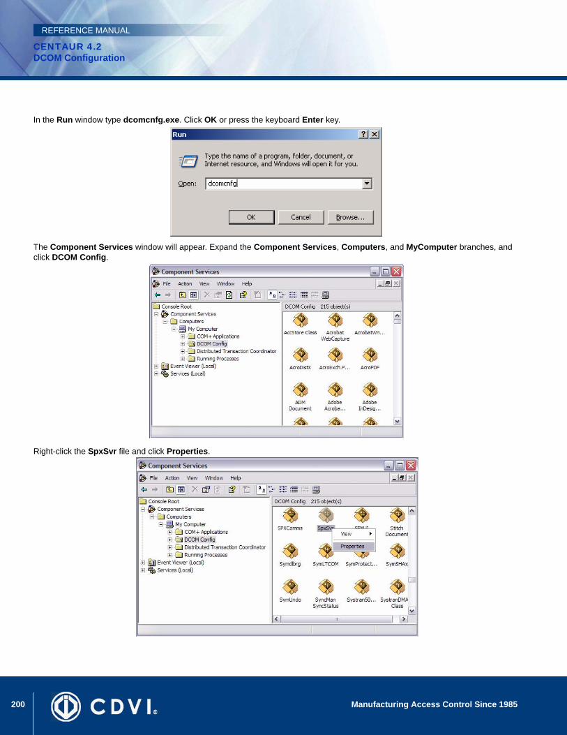
200 Manufacturing Access Control Since 1985
CENTAUR 4.2DCOM Configuration
REFERENCE MANUAL
In the Run window type dcomcnfg.exe. Click OK or press the keyboard Enter key.
The Component Services window will appear. Expand the Component Services, Computers, and MyComputer branches, and click DCOM Config.
Right-click the SpxSvr file and click Properties.
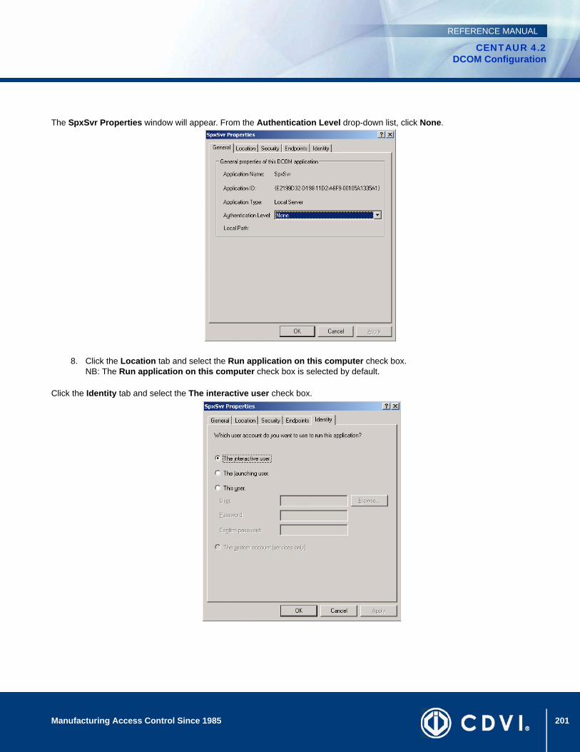
201Manufacturing Access Control Since 1985
CENTAUR 4.2DCOM Configuration
REFERENCE MANUAL
The SpxSvr Properties window will appear. From the Authentication Level drop-down list, click None.
8. Click the Location tab and select the Run application on this computer check box.NB: The Run application on this computer check box is selected by default.
Click the Identity tab and select the The interactive user check box.

202 Manufacturing Access Control Since 1985
CENTAUR 4.2DCOM Configuration
REFERENCE MANUAL
Click the Security tab to configure the user(s) that have(s) the right to access the Centaur Server computer.
a) Under Launch Permissions, click Customize.
b) Under Access Permissions, click Customize.
c) Under Configuration Permissions, click Use Default.
9. Under Launch Permissions, click the Edit button.
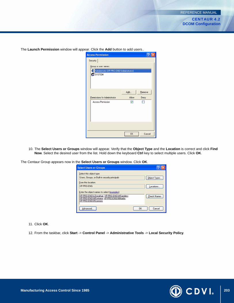
203Manufacturing Access Control Since 1985
CENTAUR 4.2DCOM Configuration
REFERENCE MANUAL
The Launch Permission window will appear. Click the Add button to add users..
10. The Select Users or Groups window will appear. Verify that the Object Type and the Location is correct and click Find Now. Select the desired user from the list. Hold down the keyboard Ctrl key to select multiple users. Click OK.
The Centaur Group appears now in the Select Users or Groups window. Click OK.
11. Click OK.
12. From the taskbar, click Start -> Control Panel -> Administrative Tools -> Local Security Policy.
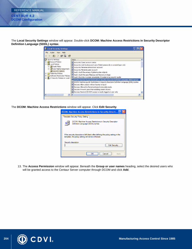
204 Manufacturing Access Control Since 1985
CENTAUR 4.2DCOM Configuration
REFERENCE MANUAL
The Local Security Settings window will appear. Double-click DCOM: Machine Access Restrictions in Security Descriptor Definition Language (SDDL) syntax.
The DCOM: Machine Access Restrictions window will appear. Click Edit Security.
13. The Access Permission window will appear. Beneath the Group or user names heading, select the desired users who will be granted access to the Centaur Server computer through DCOM and click Add.
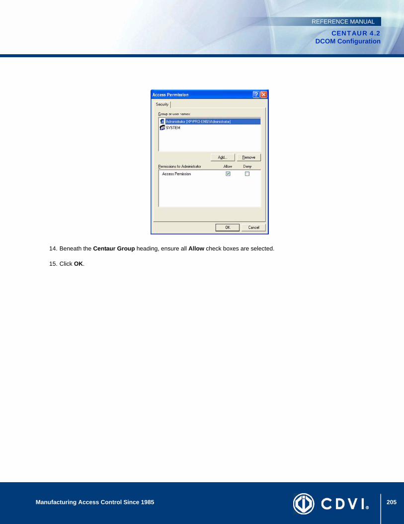
205Manufacturing Access Control Since 1985
CENTAUR 4.2DCOM Configuration
REFERENCE MANUAL
14. Beneath the Centaur Group heading, ensure all Allow check boxes are selected.
15. Click OK.
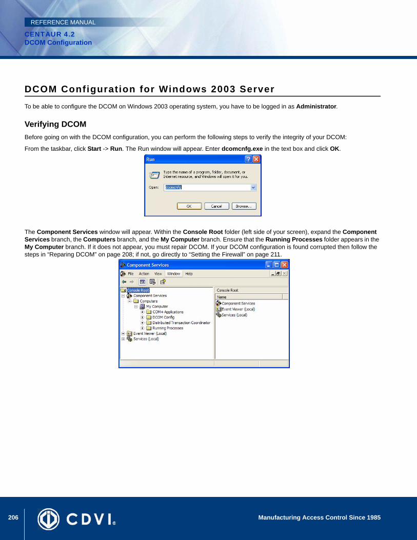
206 Manufacturing Access Control Since 1985
CENTAUR 4.2DCOM Configuration
REFERENCE MANUAL
DCOM Configuration for Windows 2003 ServerTo be able to configure the DCOM on Windows 2003 operating system, you have to be logged in as Administrator.
Verifying DCOMBefore going on with the DCOM configuration, you can perform the following steps to verify the integrity of your DCOM:
From the taskbar, click Start -> Run. The Run window will appear. Enter dcomcnfg.exe in the text box and click OK.
The Component Services window will appear. Within the Console Root folder (left side of your screen), expand the Component Services branch, the Computers branch, and the My Computer branch. Ensure that the Running Processes folder appears in the My Computer branch. If it does not appear, you must repair DCOM. If your DCOM configuration is found corrupted then follow the steps in “Reparing DCOM” on page 208; if not, go directly to “Setting the Firewall” on page 211.

207Manufacturing Access Control Since 1985
CENTAUR 4.2DCOM Configuration
REFERENCE MANUAL
Click the COM+ Applications branch. The components of this branch will appear on the right of your screen. If you get an error message and/or cannot access this branch of components, you must repair DCOM. If your DCOM configuration is found corrupted then follow the steps in “Reparing DCOM” on page 208; if not, go directly to “Setting the Firewall” on page 211.
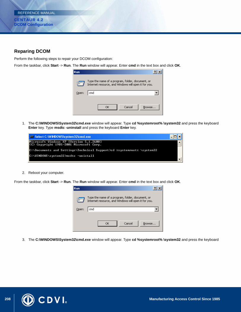
208 Manufacturing Access Control Since 1985
CENTAUR 4.2DCOM Configuration
REFERENCE MANUAL
Reparing DCOMPerform the following steps to repair your DCOM configuration:
From the taskbar, click Start -> Run. The Run window will appear. Enter cmd in the text box and click OK.
1. The C:\WINDOWS\System32\cmd.exe window will appear. Type cd %systemroot% \system32 and press the keyboard Enter key. Type msdtc -uninstall and press the keyboard Enter key.
2. Reboot your computer.
From the taskbar, click Start -> Run. The Run window will appear. Enter cmd in the text box and click OK.
3. The C:\WINDOWS\System32\cmd.exe window will appear. Type cd %systemroot% \system32 and press the keyboard

209Manufacturing Access Control Since 1985
CENTAUR 4.2DCOM Configuration
REFERENCE MANUAL
Enter key. Type msdtc -install and press the keyboard Enter key.

210 Manufacturing Access Control Since 1985
CENTAUR 4.2DCOM Configuration
REFERENCE MANUAL
Verifying if the DCOM has been repairedPerform the following steps to verify that DCOM has been repaired:
From the taskbar, click Start -> Run. The Run window will appear. Enter dcomcnfg.exe in the text box and click OK.
The Component Services window will appear. In the Console Root folder (left side of your screen), expand the Component Services branch, the Computers branch, and the My Computer branch. If there is a red arrow next to any of the components of this folder, DCOM has not been successfully repaired and you must repeat the repairing process.
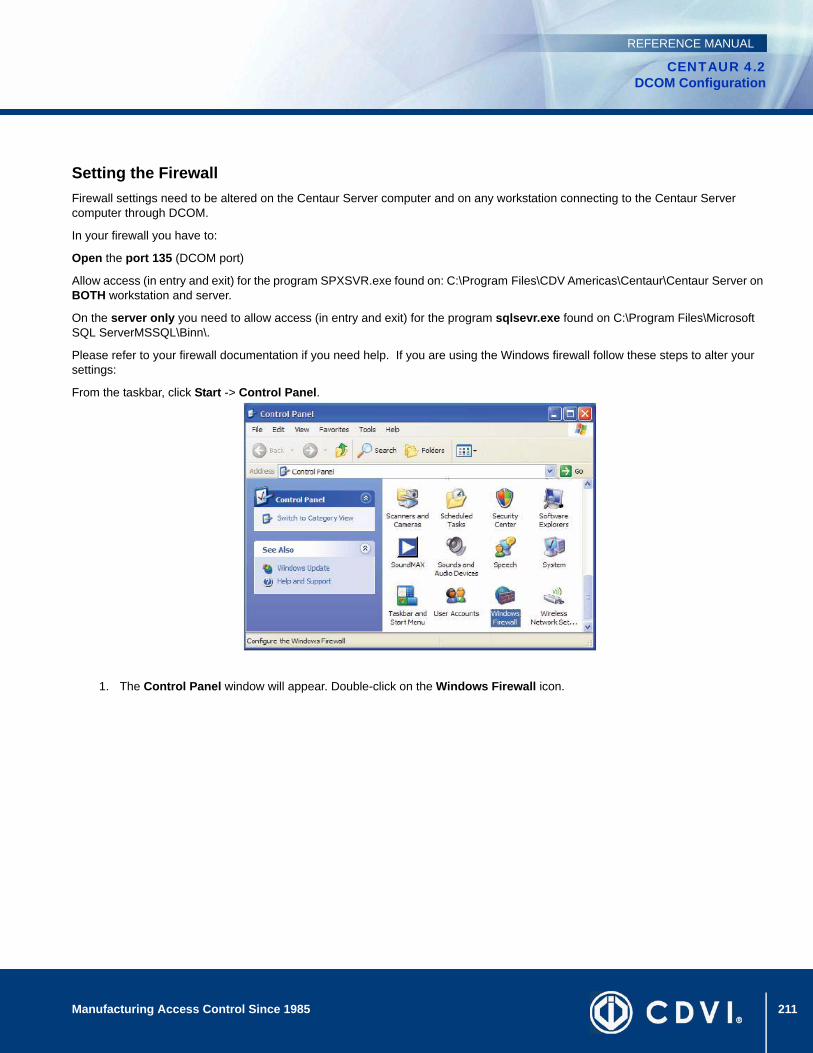
211Manufacturing Access Control Since 1985
CENTAUR 4.2DCOM Configuration
REFERENCE MANUAL
Setting the FirewallFirewall settings need to be altered on the Centaur Server computer and on any workstation connecting to the Centaur Server computer through DCOM.
In your firewall you have to:
Open the port 135 (DCOM port)
Allow access (in entry and exit) for the program SPXSVR.exe found on: C:\Program Files\CDV Americas\Centaur\Centaur Server on BOTH workstation and server.
On the server only you need to allow access (in entry and exit) for the program sqlsevr.exe found on C:\Program Files\Microsoft SQL ServerMSSQL\Binn\.
Please refer to your firewall documentation if you need help. If you are using the Windows firewall follow these steps to alter your settings:
From the taskbar, click Start -> Control Panel.
1. The Control Panel window will appear. Double-click on the Windows Firewall icon.
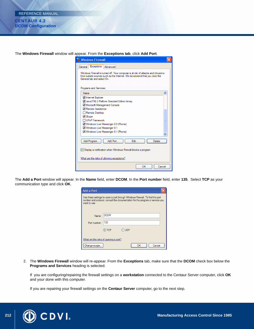
212 Manufacturing Access Control Since 1985
CENTAUR 4.2DCOM Configuration
REFERENCE MANUAL
The Windows Firewall window will appear. From the Exceptions tab, click Add Port.
The Add a Port window will appear. In the Name field, enter DCOM. In the Port number field, enter 135. Select TCP as your communication type and click OK.
2. The Windows Firewall window will re-appear. From the Exceptions tab, make sure that the DCOM check box below the Programs and Services heading is selected.
If you are configuring/repairing the firewall settings on a workstation connected to the Centaur Server computer, click OK and your done with this computer.
If you are repairing your firewall settings on the Centaur Server computer, go to the next step.
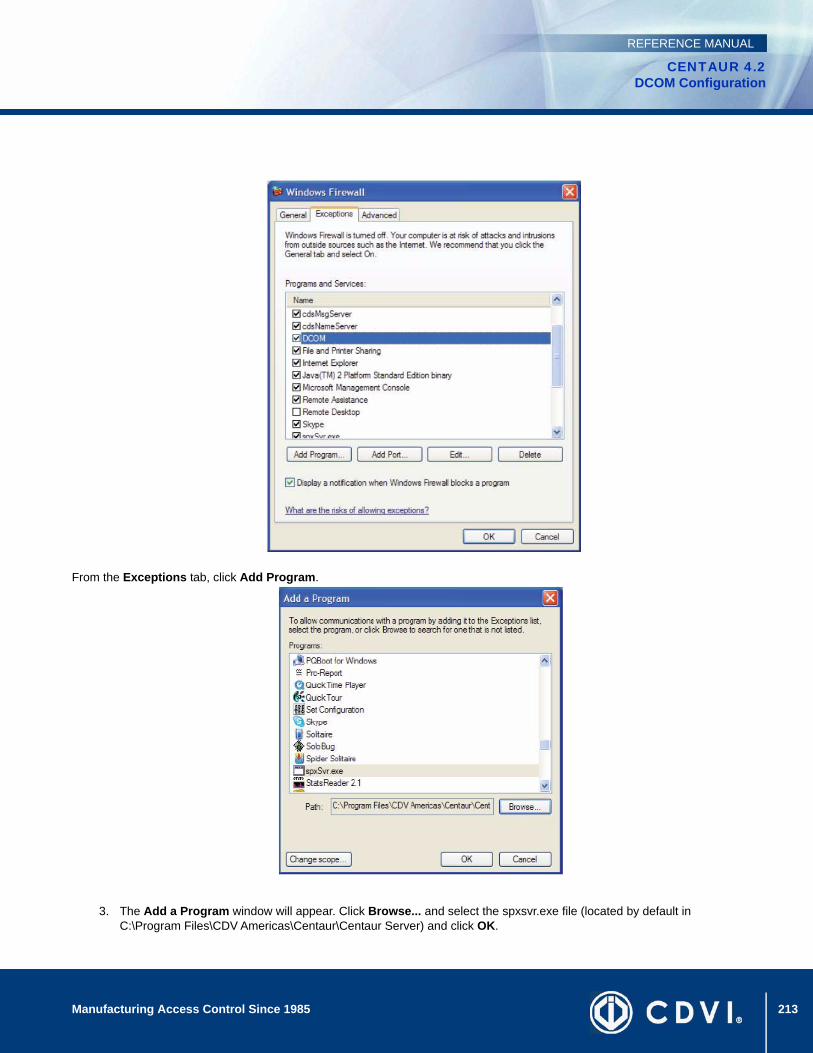
213Manufacturing Access Control Since 1985
CENTAUR 4.2DCOM Configuration
REFERENCE MANUAL
From the Exceptions tab, click Add Program.
3. The Add a Program window will appear. Click Browse... and select the spxsvr.exe file (located by default in C:\Program Files\CDV Americas\Centaur\Centaur Server) and click OK.
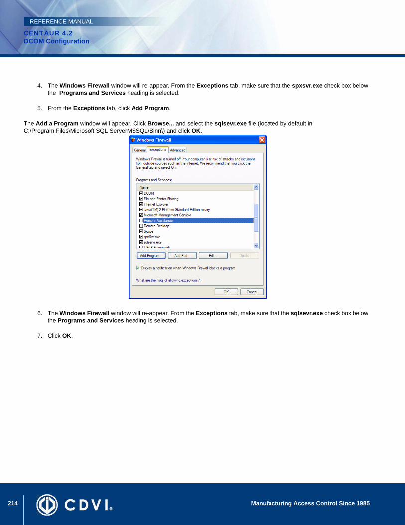
214 Manufacturing Access Control Since 1985
CENTAUR 4.2DCOM Configuration
REFERENCE MANUAL
4. The Windows Firewall window will re-appear. From the Exceptions tab, make sure that the spxsvr.exe check box below the Programs and Services heading is selected.
5. From the Exceptions tab, click Add Program.
The Add a Program window will appear. Click Browse... and select the sqlsevr.exe file (located by default in C:\Program Files\Microsoft SQL ServerMSSQL\Binn\) and click OK.
6. The Windows Firewall window will re-appear. From the Exceptions tab, make sure that the sqlsevr.exe check box below the Programs and Services heading is selected.
7. Click OK.
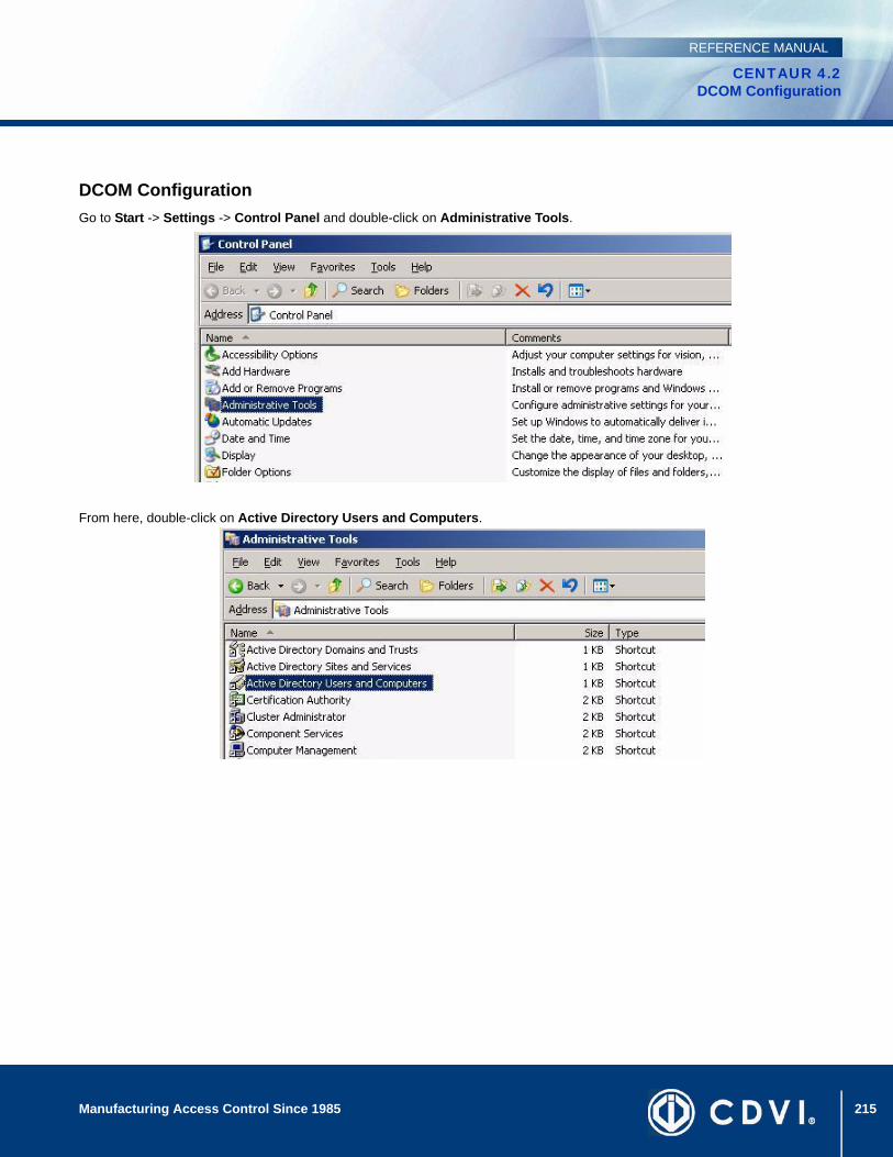
215Manufacturing Access Control Since 1985
CENTAUR 4.2DCOM Configuration
REFERENCE MANUAL
DCOM ConfigurationGo to Start -> Settings -> Control Panel and double-click on Administrative Tools.
From here, double-click on Active Directory Users and Computers.
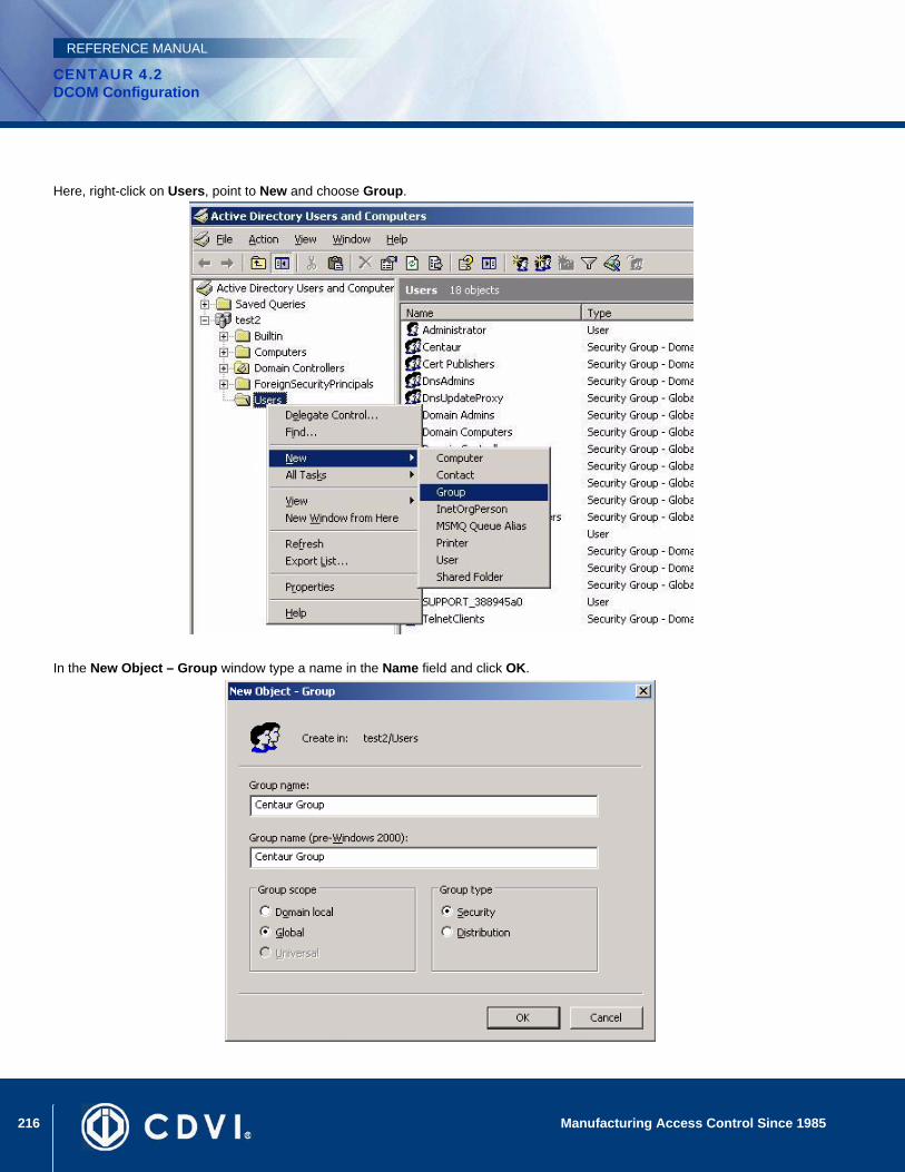
216 Manufacturing Access Control Since 1985
CENTAUR 4.2DCOM Configuration
REFERENCE MANUAL
Here, right-click on Users, point to New and choose Group.
In the New Object – Group window type a name in the Name field and click OK.
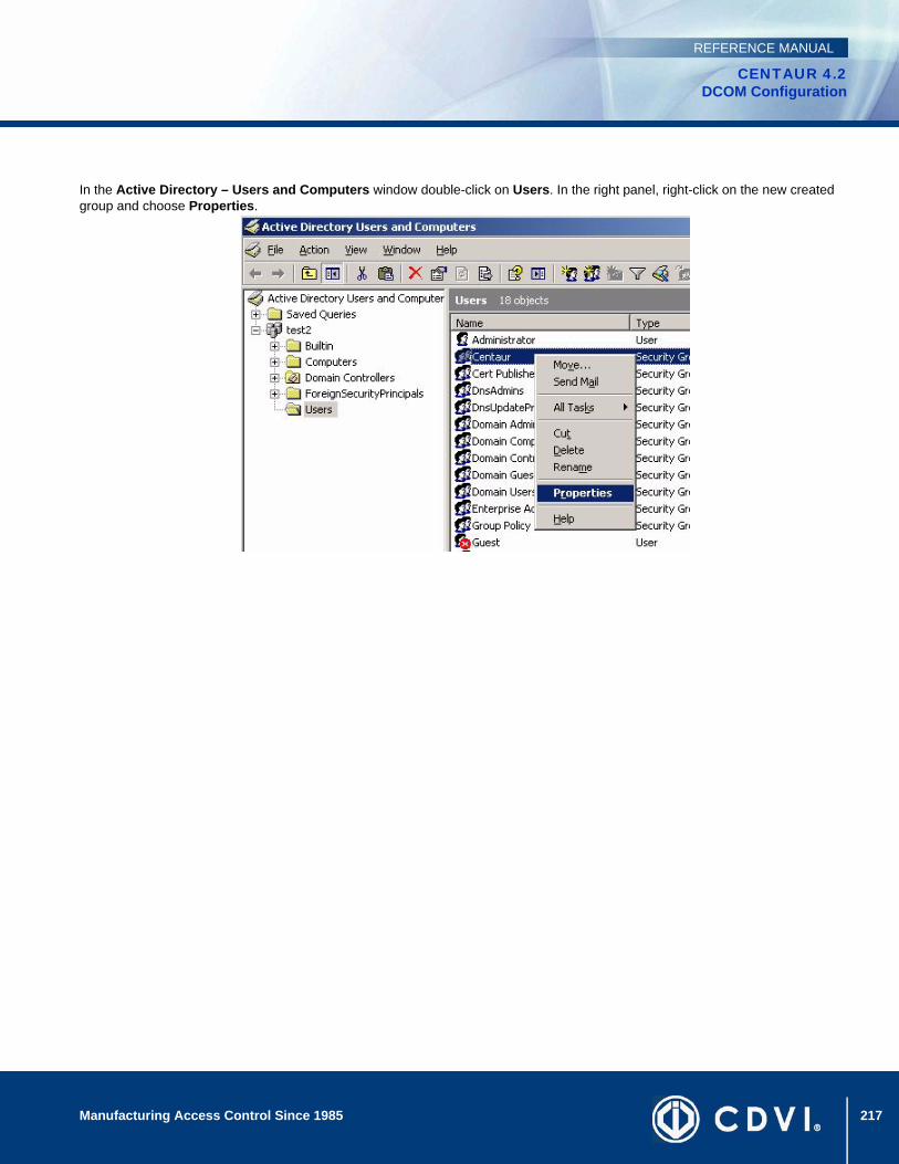
217Manufacturing Access Control Since 1985
CENTAUR 4.2DCOM Configuration
REFERENCE MANUAL
In the Active Directory – Users and Computers window double-click on Users. In the right panel, right-click on the new created group and choose Properties.
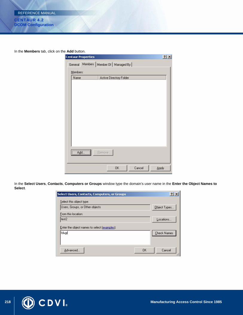
218 Manufacturing Access Control Since 1985
CENTAUR 4.2DCOM Configuration
REFERENCE MANUAL
In the Members tab, click on the Add button.
In the Select Users, Contacts, Computers or Groups window type the domain’s user name in the Enter the Object Names to Select.
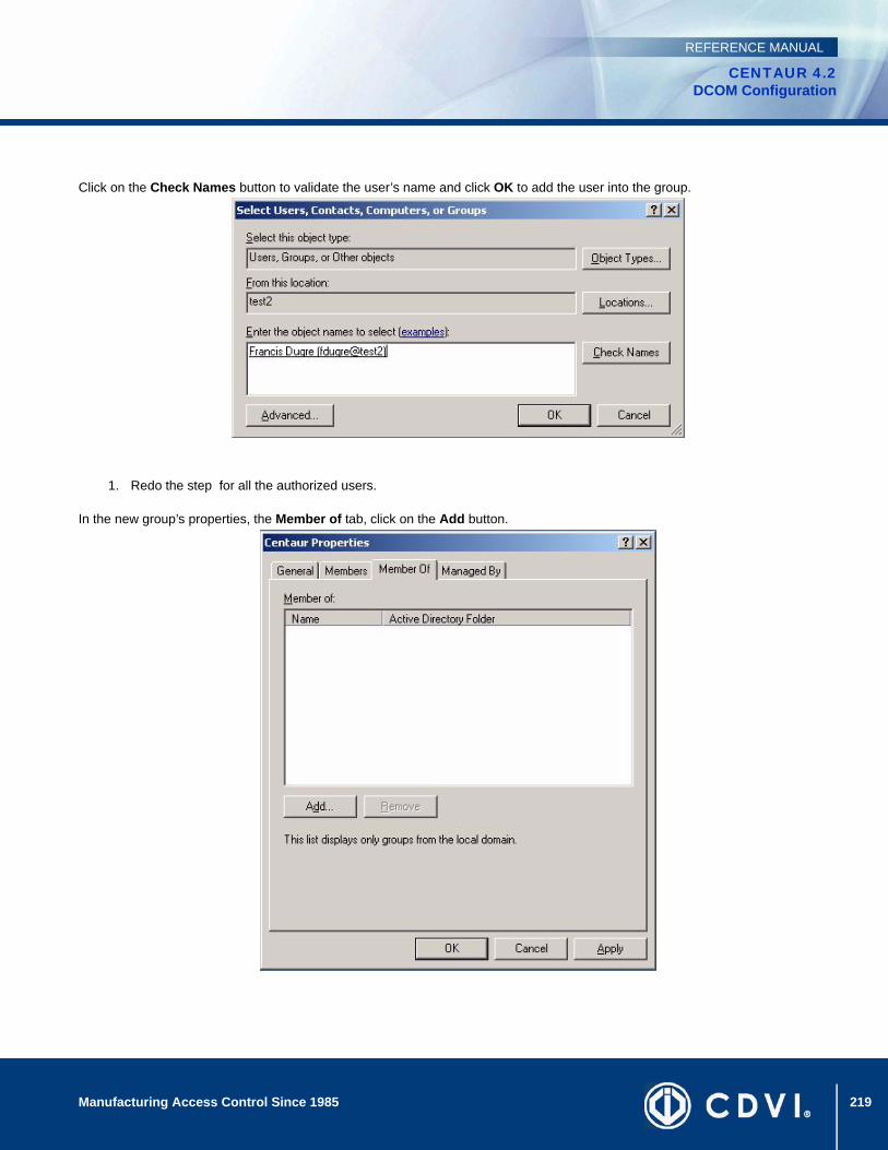
219Manufacturing Access Control Since 1985
CENTAUR 4.2DCOM Configuration
REFERENCE MANUAL
Click on the Check Names button to validate the user’s name and click OK to add the user into the group.
1. Redo the step for all the authorized users.
In the new group’s properties, the Member of tab, click on the Add button.

220 Manufacturing Access Control Since 1985
CENTAUR 4.2DCOM Configuration
REFERENCE MANUAL
In the Select Groups window, type the model’s users in the Enter the Object Names to Select.
Click on the Check Names button to validate the group’s name and click OK.
Click on Start in Windows, type dcomcnfg and click OK.

221Manufacturing Access Control Since 1985
CENTAUR 4.2DCOM Configuration
REFERENCE MANUAL
2. From Console Root expand the Component Services, Computers, and My Computer.
3. In the Default Protocols tab, check if the Connection-oriented TCP/IP exists in the DCOM Protocols window; if not, add
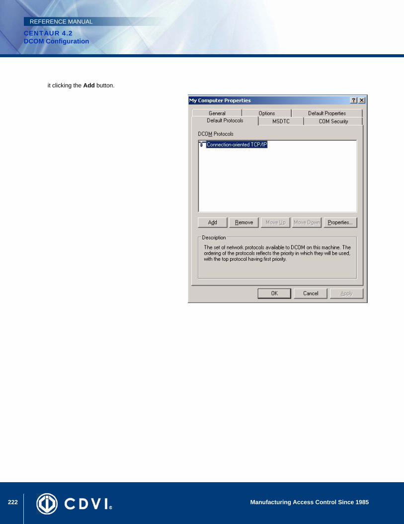
222 Manufacturing Access Control Since 1985
CENTAUR 4.2DCOM Configuration
REFERENCE MANUAL
it clicking the Add button.

223Manufacturing Access Control Since 1985
CENTAUR 4.2DCOM Configuration
REFERENCE MANUAL
4. In the MSDTC tab, check if the Service Control Status for MSDTC is running.

224 Manufacturing Access Control Since 1985
CENTAUR 4.2DCOM Configuration
REFERENCE MANUAL
5. In the Default Properties tab, check if the Enable Distributed COM on this computer check box is selected.
Click on Start in Windows, type dcomcnfg, and click OK.

225Manufacturing Access Control Since 1985
CENTAUR 4.2DCOM Configuration
REFERENCE MANUAL
The Component Services window will appear. Expand the Component Services, Computers, and My Computer branches, and click DCOM Config.
Right-click the SpxSvr file and click Properties.
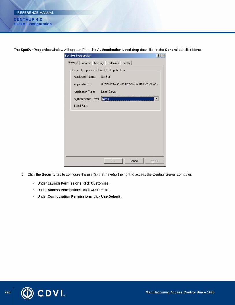
226 Manufacturing Access Control Since 1985
CENTAUR 4.2DCOM Configuration
REFERENCE MANUAL
The SpxSvr Properties window will appear. From the Authentication Level drop-down list, in the General tab click None.
6. Click the Security tab to configure the user(s) that have(s) the right to access the Centaur Server computer.
• Under Launch Permissions, click Customize.
• Under Access Permissions, click Customize.
• Under Configuration Permissions, click Use Default.
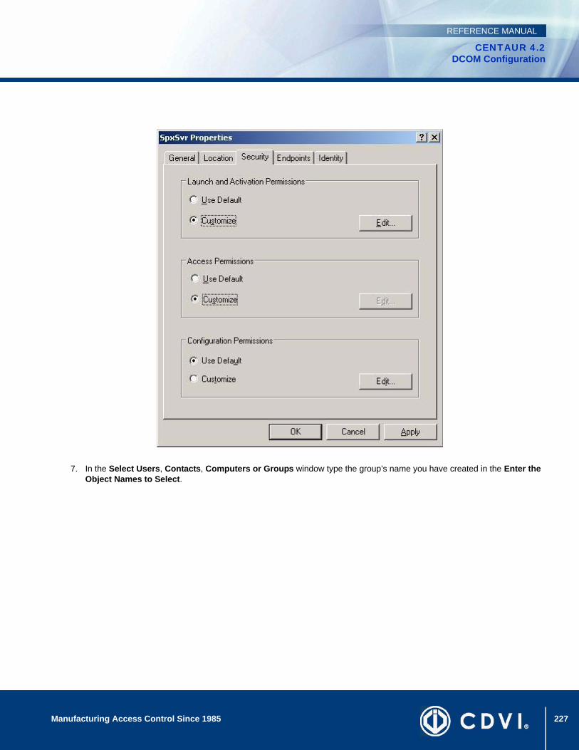
227Manufacturing Access Control Since 1985
CENTAUR 4.2DCOM Configuration
REFERENCE MANUAL
7. In the Select Users, Contacts, Computers or Groups window type the group’s name you have created in the Enter the Object Names to Select.
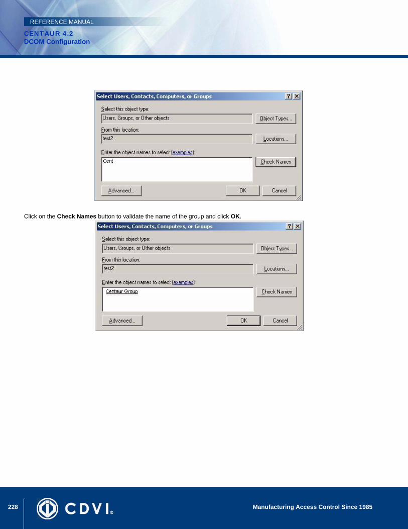
228 Manufacturing Access Control Since 1985
CENTAUR 4.2DCOM Configuration
REFERENCE MANUAL
Click on the Check Names button to validate the name of the group and click OK.

229Manufacturing Access Control Since 1985
CENTAUR 4.2DCOM Configuration
REFERENCE MANUAL
Select the four check boxes in the Permisions for Centaur window and click OK.

230 Manufacturing Access Control Since 1985
CENTAUR 4.2DCOM Configuration
REFERENCE MANUAL
In the Security tab click on the Modify button to change the Access Permisions section.
In the Select Users, Contacts, Computers or Groups window type the group’s name you have created in the Enter the Object Names to Select.
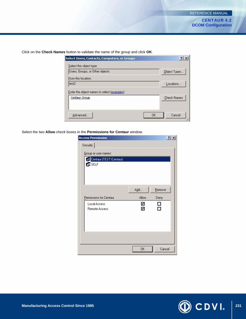
231Manufacturing Access Control Since 1985
CENTAUR 4.2DCOM Configuration
REFERENCE MANUAL
Click on the Check Names button to validate the name of the group and click OK.
Select the two Allow check boxes in the Permissions for Centaur window.
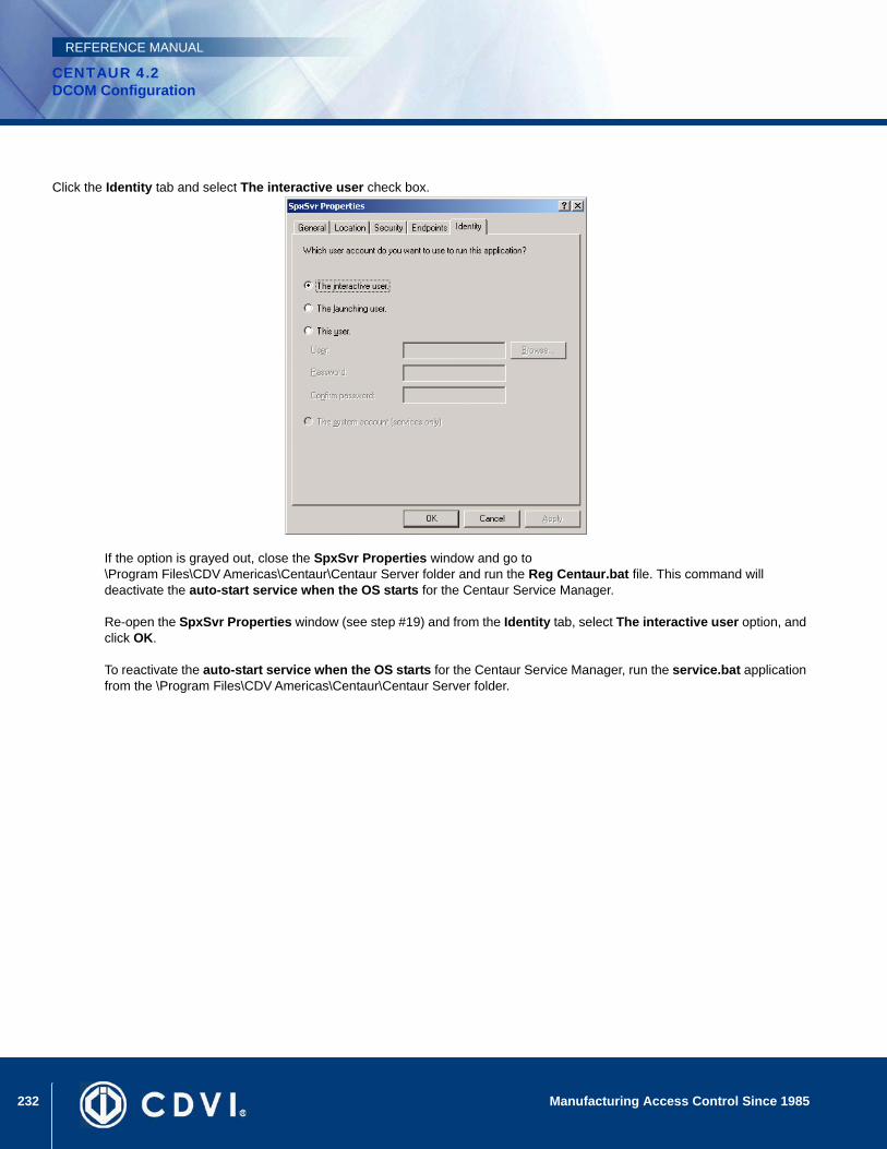
232 Manufacturing Access Control Since 1985
CENTAUR 4.2DCOM Configuration
REFERENCE MANUAL
Click the Identity tab and select The interactive user check box.
If the option is grayed out, close the SpxSvr Properties window and go to \Program Files\CDV Americas\Centaur\Centaur Server folder and run the Reg Centaur.bat file. This command will deactivate the auto-start service when the OS starts for the Centaur Service Manager.
Re-open the SpxSvr Properties window (see step #19) and from the Identity tab, select The interactive user option, and click OK.
To reactivate the auto-start service when the OS starts for the Centaur Service Manager, run the service.bat application from the \Program Files\CDV Americas\Centaur\Centaur Server folder.
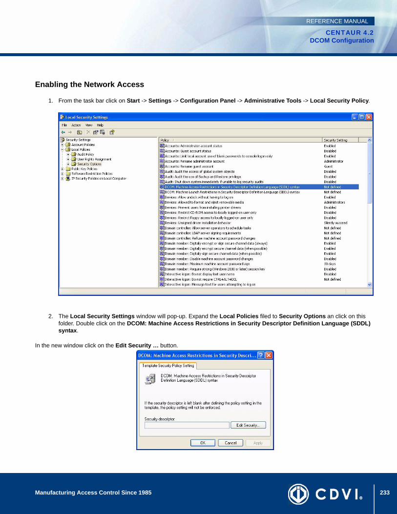
233Manufacturing Access Control Since 1985
CENTAUR 4.2DCOM Configuration
REFERENCE MANUAL
Enabling the Network Access
1. From the task bar click on Start -> Settings -> Configuration Panel -> Administrative Tools -> Local Security Policy.
2. The Local Security Settings window will pop-up. Expand the Local Policies filed to Security Options an click on this folder. Double click on the DCOM: Machine Access Restrictions in Security Descriptor Definition Language (SDDL) syntax.
In the new window click on the Edit Security … button.
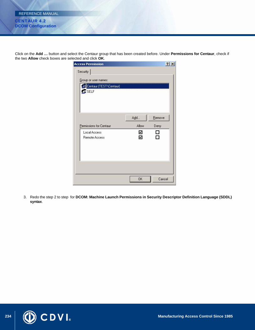
234 Manufacturing Access Control Since 1985
CENTAUR 4.2DCOM Configuration
REFERENCE MANUAL
Click on the Add … button and select the Centaur group that has been created before. Under Permissions for Centaur, check if the two Allow check boxes are selected and click OK.
3. Redo the step 2 to step for DCOM: Machine Launch Permissions in Security Descriptor Definition Language (SDDL) syntax.
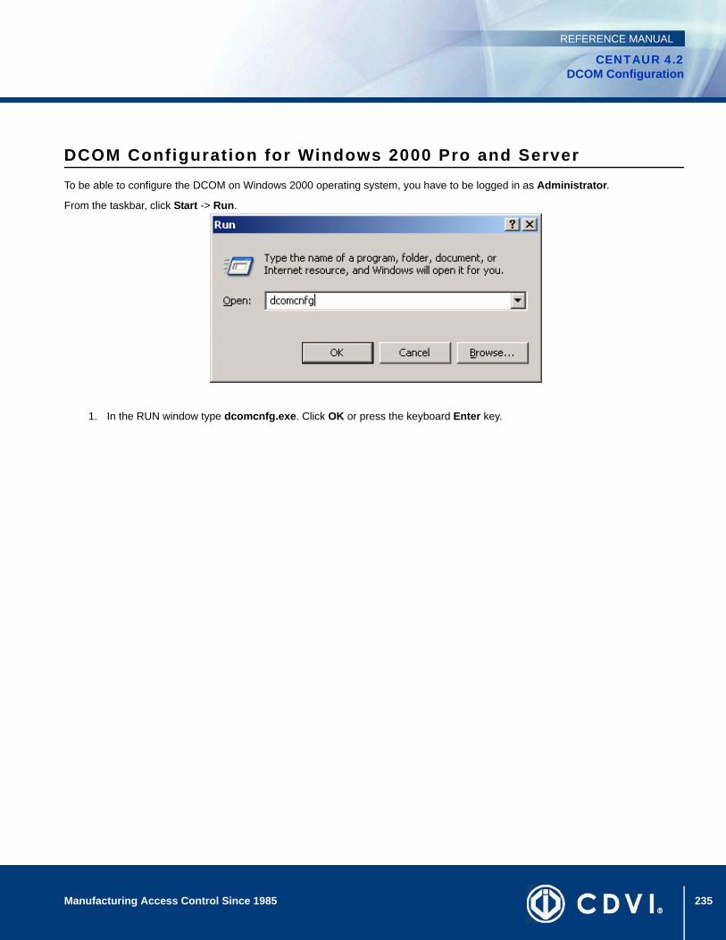
235Manufacturing Access Control Since 1985
CENTAUR 4.2DCOM Configuration
REFERENCE MANUAL
DCOM Configuration for Windows 2000 Pro and ServerTo be able to configure the DCOM on Windows 2000 operating system, you have to be logged in as Administrator.
From the taskbar, click Start -> Run.
1. In the RUN window type dcomcnfg.exe. Click OK or press the keyboard Enter key.

236 Manufacturing Access Control Since 1985
CENTAUR 4.2DCOM Configuration
REFERENCE MANUAL
The Distributed COM Configuration Properties window pops up. Highlight SpxSvr from the list and click on Properties.
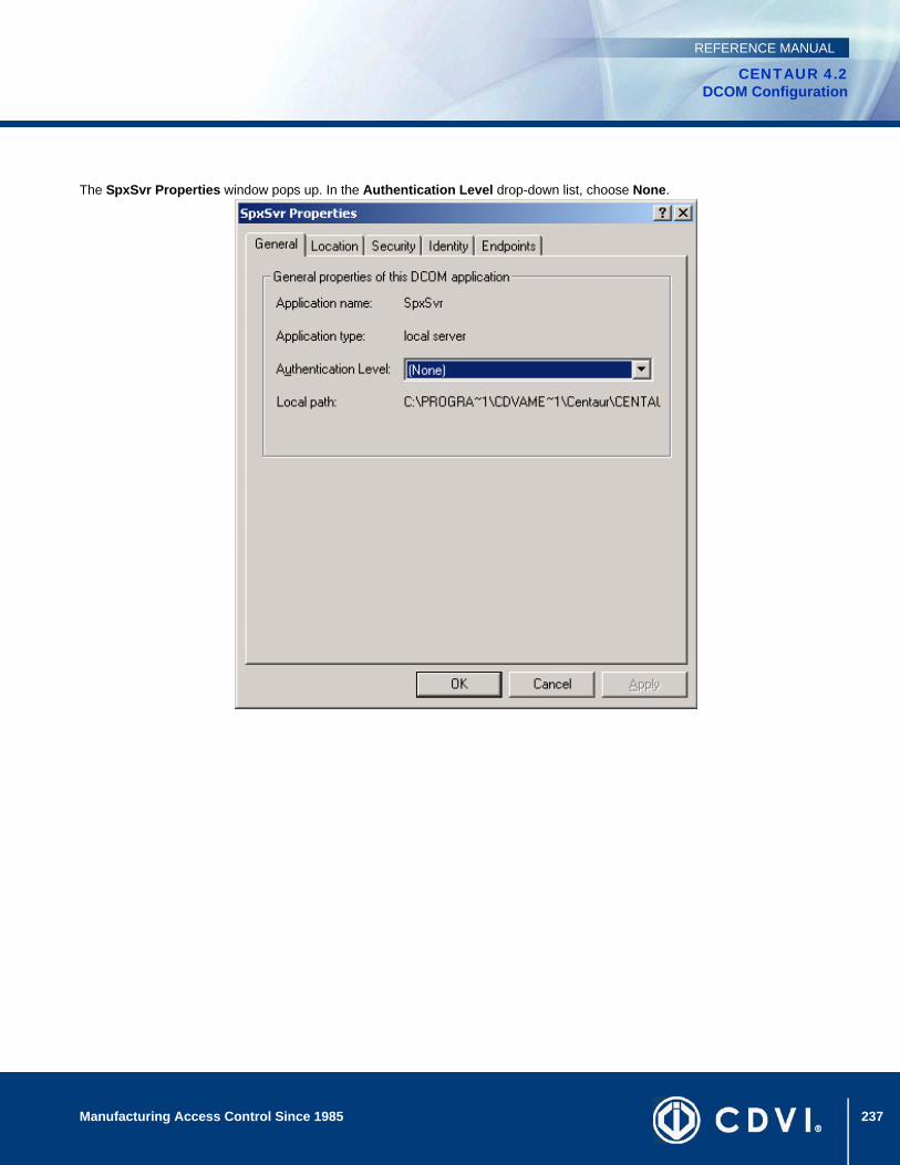
237Manufacturing Access Control Since 1985
CENTAUR 4.2DCOM Configuration
REFERENCE MANUAL
The SpxSvr Properties window pops up. In the Authentication Level drop-down list, choose None.

238 Manufacturing Access Control Since 1985
CENTAUR 4.2DCOM Configuration
REFERENCE MANUAL
Click on the Location tab and select the Run application on this computer check box.NB: The Run application on this computer check box is selected by default.
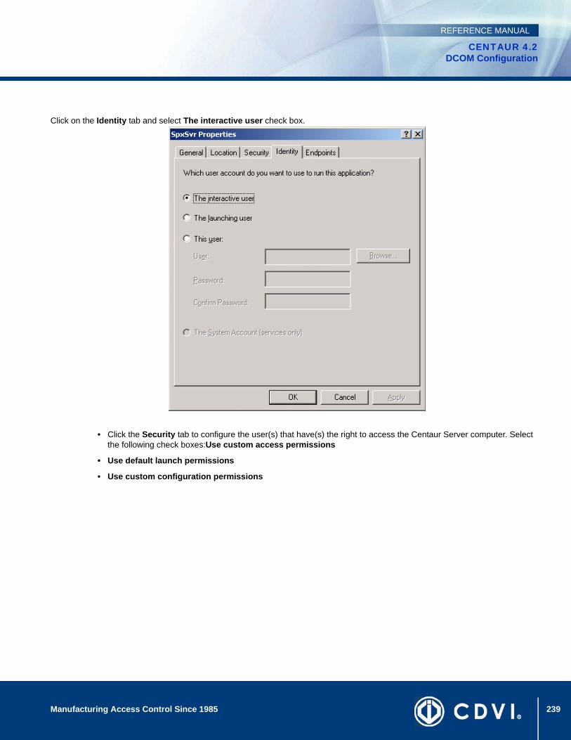
239Manufacturing Access Control Since 1985
CENTAUR 4.2DCOM Configuration
REFERENCE MANUAL
Click on the Identity tab and select The interactive user check box.
• Click the Security tab to configure the user(s) that have(s) the right to access the Centaur Server computer. Select the following check boxes:Use custom access permissions
• Use default launch permissions
• Use custom configuration permissions
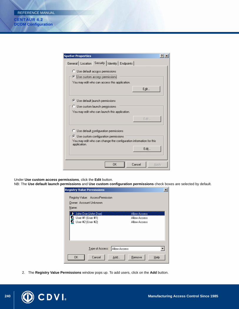
240 Manufacturing Access Control Since 1985
CENTAUR 4.2DCOM Configuration
REFERENCE MANUAL
Under Use custom access permissions, click the Edit button.NB: The Use default launch permissions and Use custom configuration permissions check boxes are selected by default.
2. The Registry Value Permissions window pops up. To add users, click on the Add button.

241Manufacturing Access Control Since 1985
CENTAUR 4.2DCOM Configuration
REFERENCE MANUAL
The Use default launch permissions and Use custom configuration permissions check boxes are selected by default.
The Registry Value Permissions window may be empty, depending on the previous DCOM configurations.
The Add Users and Groups window pops up. From the List Names From drop down list, select the computer or domain. To view the list of users, either click Show Users or if the user is part of a user group, select the group and click Members. Select the desired user from the list. Hold down the keyboard Ctrl key while left clicking to select multiple users. Click Add and OK.
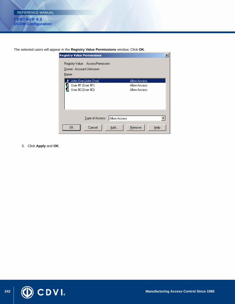
242 Manufacturing Access Control Since 1985
CENTAUR 4.2DCOM Configuration
REFERENCE MANUAL
The selected users will appear in the Registry Value Permissions window. Click OK.
3. Click Apply and OK.

243
CENTAUR 4.2Access Control Software
Manufacturing Access Control Since 1985
REFERENCE MANUAL
Appendix B: Warranty
CDVI Americas Ltd. (“Seller”) warrants its products to be free from defects in materials and workmanship under normal use for the period of one year. Except as specifically stated herein, all express or implied warranties whatsoever, statutory or otherwise, including without limitation, any implied warranty of merchantability and fitness for a particular purpose, are expressly excluded. Because Seller does not install or connect the products and because the products may be used in conjunction with products not manufactured by Seller, Seller cannot guarantee the performance of the security system and shall not be responsible for circumstances resulting from the product’s inability to operate. Seller obligation and liability under this warranty is expressly limited to repairing or replacing, at Seller’s option, any product not meeting the specifications. Returns must include proof of purchase and be within the warranty period. In no event shall the Seller be liable to the buyer or any other person for any loss or damages whether direct or indirect or consequential or incidental, including without limitation, any damages for lost profits, stolen goods or claims by any other party, caused by defective goods or otherwise arising from the improper, incorrect or otherwise faulty installation or use of the merchandise sold.
Notwithstanding the preceding paragraph, the Seller’s maximum liability will be strictly limited to the purchase price of the defective product. Your use of this product signifies your acceptance of this warranty.
BEWARE: Dealers, installers and/or others selling the product are not authorized to modify this warranty or make additional warranties that are binding on the Seller.
For technical support in Canada or the U.S., call 1-866-610-0102, Monday to Friday from 8:00 a.m. to 8:00 p.m. EST. For technical support outside Canada and the U.S., call 00-1-450-682-7945 , Monday to Friday from 8:00 a.m. to 8:00 p.m. EST. Please feel free to visit our website at www.cdvi.ca.
©2006-2008 CDVI Americas Ltd. All rights reserved. Specifications may change without prior notice. One or more of the following US patents may apply: 6215399, 6111256, 5751803, 5721542, 5287111, 5119069, 5077549, 5920259, 5886632. Canadian and international patents may also apply.Centaur is a trademark or registered trademark of CDVI Americas Ltd. or its affiliates in Canada, the United States and/or other countries.

244 Manufacturing Access Control Since 1985
CENTAUR 4.2Warranty
REFERENCE MANUAL
245
CENTAUR 4.2Access Control Software
Manufacturing Access Control Since 1985
REFERENCE MANUAL
INDEX
Symbols.wav Player 153, 181
Numerics2R Connection 1173R Connection 118
AAbnormal Events 164Abnormal events 17Access Denied, Output Activation Events 129Access Events 164Access events 17Access Granted, Output Activation Events 129Access Level Active 84Access Level Assignment, Cards 92Access Level Programming 83Access Level Properties
Access Level Tab 84, 150Doors & Schedules Tab 85
Access Rights, Operator 152Access Time-out, Output Activation Events 129Access, Door Type 71Acknowledged Events 137, 164Acknowledged events 17Acknowledging Alarms 138Action 136Activate a Relay Group 145Activate Output 169Activate Output (Timed) 169Activate Relay, Anti-passback 60
ActivatingDevices via Events 136Outputs Manually 131, 169Relay Groups 123Relays Manually 166
Activating Outputs, Door Programming 78Activating Schedule
Relays 112Timed Relays 111
Activation Tab, Relays 111Activation Time, Outputs 128Activation Timer for Relays 112Active
Access Level 84Controller Communications 59Schedules 45
Add a New Card, Centaur’s Card Management feature 97Adding
Batch of Cards 89Card(s) 89CCTV Commands 156Controllers 50Doors 68Groups 142Inputs 119Outputs 127Relays 110Security Levels, Permissions and Operators 148
Adding a holiday 40Address
Access Level 84Controller 52
246 Manufacturing Access Control Since 1985
CENTAUR 4.2
REFERENCE MANUAL
Doors 69Groups 143Inputs 119Operator 149Outputs 127Relays 110Security Level 149
Alarm Acknowledgement 137Alarm Acknowledgement Options 160Alarm Acknowledgment
Enabling 137Schedule 137
Alarms Window 21All events 17All Events, Displaying 164All, Security Levels 150Alternate Floor Group 143Anti-passback Override 93Anti-passback Reset Input 60Anti-passback Reset Schedule 60Anti-passback Schedule 60Anti-passback Status, Output Activation Events 129Anti-passback Tab 60ASCII Command 140Assigning a .wav File to an Event 182Assigning Access Levels, Cards 92Assigning Controller Addresses 53Assigning Floor Groups, Cards 92Attaching Databases 175ATZ 2R 57ATZ 2R Connection 117ATZ 3R 57ATZ 3R Connection 118
BBacking up Databases 173Backup Scheduler 178Badge editor 99Baud Rate 30Beep
On Alarms 160On All Abnormal Events 160On All Access Events 160On All Events 160
bling 84Buffering, Offline 32Bypass input group 121Bypassing Inputs 121
CCamera, CCTV Command 157Card Fields 32Card Import/Export 13, 18, 153
Card Number 91Card Number and Card Number (HEX) 92Card Options 93Card Settings 91Card Status 94Card Traced 93Card, Distributed Programming 33Cardholder Details 94Cards 87
Photo 95CCTV Command Properties
General Tab 156CCTV Control
Enabling for an Event 140Protocol 140Schedule for an Event 140
CCTV port settings 36Centaur Card Import/Export Feature 102Centaur Database Management Tools 171Centaur Databases 172Centaur Editions 2Centaur Service Manager 153Centaur’s Anti-Passback Monitoring Software 153Centaur’s Card Management feature 96Centaur’s Real-Time Graphic Interface Feature 153Centaur’s Report Generation feature 153Centaur’s Visual Authentication Software 153CMPP card enrolment station 37CMPP Module, Centaur’s Card Management feature 97Colour Definitions, Events 161COM Port Assignment 30Command, CCTV 140Communication 22
Baud Rate Setting 30COM Port Assignment 30Controller Options 57Dialup 28Direct (serial port) 27Phone Number 31Speed 30TCP/IP 29Update CTL Every 15 Minutes 32
Communication Type 24Computer requirements 7Configuration Tab, Controllers 55Configuring Doors 55, 61Configuring Inputs 57, 121Connecting and Disconnecting 35Connecting Inputs 116Control Input Status 168Control Output Status 131, 169Control Type, Lock 73Controller Addresses, Dip Switches 53
247Manufacturing Access Control Since 1985
CENTAUR 4.2
REFERENCE MANUAL
Controller Configuration Wizard 50Controller Properties
Anti-passback Tab 60Configuration Tab 55, 61Controller Tab 52
Controller Reset 65Controller Response Delay 59Controller Status 65, 167Controller status 17Controller Time-Out 59Controllers 49Controlling Database Sizes 174Crossover Periods 46Custom CCTV Command 157Custom Reader Format 63Customizing Event Colours 161
DDatabase Backup Scheduler 13, 18, 153, 178Database File Management 153Database Management 13, 18, 171Database Management Module 172Database Size 174Database Tab, Security Levels 150Database Tree View Window 21Databases, description 172Days Before End Date 94DCOM Configuration for Windows 2000 Pro and Server 235DCOM Configuration for Windows 2003 Server 206DCOM Configuration for Windows XP 184Deactivate a Relay Group 145Deactivate Output 169Deactivate Relays Manually 166De-energized, Lock Control 73De-energized, Relay State 113Default Event Definition 134Default Logon ID and Password 11Default System Event Colours 161Definable Card Fields 32Defining Card Badge 98Defining Holidays 41Delay Controller Response 59Delete A Card, Centaur’s Card Management feature 97Delete, Security Levels 150Deleting
Access Levels 86Cards 95CCTV Commands 157Controllers 62Doors 80Groups 145Holidays 41Inputs 124
Outputs 131Relays 113Schedules 47Security Levels, Permissions or Operators 154Sites 38
Deleting Databases 175, 176Deleting Databases. See also Purging Databases and Remov-ing DatabasesDetaching Databases 176Details Tab, Holiday Programming 40Details Tab, Schedule Programming 45Device 136Device Activation, Events 136Device-Specific Event Definition 134Diagnostic Tool 13, 18, 154Dial-up Number 31Dialup Site 28Dip Switches, Controllers 53Direct (Serial Port) Connection 27Disable a Door Group 145Disable Door Manually 165Disable Input Manually 168Disconnecting 38Disk, Event Definitions 135Display
Abnormal Events 164Access Events 164Acknowledged Events 164All Events 164Controller Status 167Door Status 81Input Status 168Output Status 169Relay Status 113, 166
Display Door Status 81Display Notification Message 160Displaying Events 164Distributed Card Programming 33Door Configuration 55Door Expander’s Configuration 61Door Forced Open, Output Activation Events 130Door Groups
also see Groups 144Assigning Doors to a Door Group 144Enable or Disable 145Lock or Unlock 145
Door Input 76Door Open Pre-alarm, Output Activation Events 130Door Open Too Long, Output Activation Events 130Door Open, Output Activation Events 130Door Properties
Door Tab 69Elevator Control 79
248 Manufacturing Access Control Since 1985
CENTAUR 4.2
REFERENCE MANUAL
General Tab 71Inputs and Outputs 76
Door status 17Door Tab 69Door Timers 74Door Type 71Door Unlock Schedule 73Door Unlocked, Output Activation Events 130Doors 67Doors & Schedules, Access Levels 85Download 64
EEditing a Scheduled Database Backup 179Elevator Control 79, 105Elevator, Door Type 71E-Mail Activation 139Enable a Door Group 145Enable Card Traced 94Enable Door Manually 165Enable Input 168Enabling a Schedule 45Enabling Schedule for Inputs 121Enabling the Access Level 84End Date 94End Time 46Energized, Lock Control 73Energized, Relay State 113Entry, Door Type 71Entry, Global 71Entry/Exit, Unlock Both 61Event Colour Definitions 161Event Database 172Event Database Size 174Event Definition 133
Alarms Tab 137CCTV Control tab 140Command 140General Tab 135Instructions 137Requires Acknowledgement 137Schedule 135, 136, 137, 139, 140Selecting Events 134Video Switcher Protocol 140
Event Display 164Event Options 160Event Request 59Events
Display Abnormal 164Display Access 164Display Acknowledged 164Display All 164WAV file assignment 182
Events Colours 17Events, Output Activation 128Exit, Door Type 71Exit, Global 71Exporting Cards 102Extended Access 93Extended Access Levels (Levels 3/4) 33Extended Access Time 75
FFamily Number 91Family Number, Maximum 34Fast Event Request 59File 17Firmware Update 63Floor Group Properties
Floors 143Floor Group, Alternate 143Floor Groups
Assigning Floors 143Selecting a Schedule 143Setting an Alternate Floor Group 143
Floors 143Definition 35Number of 35Schedules for each 79
FontCard 18FrontCard 13, 152FrontGuard 13, 18FrontView 13, 18
GGeneral Centaur Options 160General Controller Properties 52General Door Properties 69General Holiday Properties 40General Properties
Schedules 45General Properties for Security Levels, Permissions and Opera-tors 149General Tab, Door Programming 71Generate Unique PIN 33Global Entry/Exit 71Groups 141, 142
Floors 92Groups, Are Used Where 142Groups, Holiday 41
HHardlock key 10Hard-passback 60Headcount 18

249Manufacturing Access Control Since 1985
CENTAUR 4.2
REFERENCE MANUAL
Help 18Hexadecimal Card Numbers 33Holiday Groups in Schedules 47Holiday Properties
Details Tab 40Holiday Tab 40
Holiday Tab 40Holidays 39Holidays and Holiday Groups 41
IImporting Cards 103Input Configuration 57Input Configuration for
Anti-passback Reset 60Doors 76Interlock 77Mantrap 77REX 76
Input Connections 116Input Groups
also see Groups 144Assigning Inputs to an Input Group 144
Input PropertiesBypassing Inputs 121Details Tab 121Input Configuration 121Input Enabling Schedule 121Input Response Time 121Input Tab 119
Input Speed 121Input status 17Input Status Display 168Input Tab 119Inputs 115Inputs and Outputs Tab 76Installation & Use 1Installation, Centaur Administration Console (Workstation) 7Installing/updating the Administration Console 8Installing/Updating the Centaur Software 5Instructions 137Interlock Inputs 77Interlock Override 93Invalid, Cards 94Inverted, Output 128IP Address 57
KKeyboard 22Keypad Schedule 73Keypad Time-out, Output Activation Events 129Keypad Type 56
Keypad Type, Door Expansion Module 61Keypad, Controllers 55
LLAN 29Languages 22Latched Relay Activation (Manually) 166Late to Open, Unlock On 73Launching Centaur 11Limiting the Event Database’s Size 174Locator 13, 18Lock a Door Group 145Lock Control 73Lock Control Entry/Exit Doors 61Lock Door 165Log Com. Failure 59Log File 17Logon ID, Setting the Operator’s Access Rights 152Lost Cards 94
MMain Database 172Make a Beep on All Abnormal Events 160Make a Beep on All Access Events 160Make a Beep on all Events 160Mantrap Inputs 77Manual Control of Door and Relay Groups 145Manual Controls 163, 165Manual Controls, Security Levels 151Maximum Family Number 34Menu 17Modem 31Modify, Security Levels 150Modifying
Access Levels 84Cards 91CCTV Commands 156Controllers 52Doors 69Groups 143Holidays 40Inputs 119Outputs 127Relays 110Schedules 44Security Levels, Permissions or Operators 149
Modifying a Site 27Modules 18Modules Tab, see Software Modules 152Monitor, CCTV Command 157MSDE Management. See also Database Backup Scheduler
250 Manufacturing Access Control Since 1985
CENTAUR 4.2
REFERENCE MANUAL
NName
Access Level 84Controllers 54Doors 70Holidays 40Outputs 128Relays 111Schedules 45Security Level, Permission or Operator 149
NC Input Connection 116NC Inputs 57Non-activated Status, Relays 113None, Security Levels 150Normal State (NO/NC), Inputs 121Notes
Access Level 84Controller 54Doors 70Holidays 40Outputs 128Relays 111Schedules 45Security Level, Permission or Operator 149
OOffline Buffering 32Open Too Long Time 74Opened, Reading Type 73Operating system requirements 7Operations Tab, Security Levels 151Operator Timeout 17Operators 147, 152Options 17, 159
Alarm Acknowledgement 160Events 160Status Display 161
Options, Cards 93Outbox 32Output Activation 78Output Programming 126Output Properties
Activation Time 128Events Tab 128Inverted 128Output Tab 127
Output Status 131, 169Output status 17Output Timing Properties
Timings 130Outputs 125Override Anti-passback 93Override Interlock 93
Overview of Output Programming 126
PP.I.N. 93
Generate Unique 33Password, Setting the Operator’s Access Rights 152Pending Cards 94Periods 45Photo 95Poll Door Expander Status Non-Stop 61Poll Timeout 59Port Number 57Pre-alarm Time 74Preset, CCTV Command 157Print Card Information, Centaur’s Card Management feature 97Print the card, Centaur’s Card Management feature 97Programming Rights, Security Levels 150Pro-Report 13, 18Protocol, CCTV 140Purging Databases 177
RReader 72Reader Disabled, Output Activation Events 130Reader Format Custumization 63Reader Type 56Reader Type, Door Expansion Module 61Reader, Controllers 55Reading Device 72Reading Type Options 73Real-Time Events/Status Window 21Refresh 17Refresh, Centaur’s Card Management feature 97Relay Activation Time 112Relay Groups
Activate or Deactivate 145also see Groups 144Assigning Relays to a Relay Group 144
Relay PropertiesActivation Tab 111Relay Tab 110
Relay State 113Relay status 17Relay Tab 110Relay, Activate with Anti-Passback 60Relays 109Repeat Sound Every 182Requires Acknowledgment 137Reset Anti-passback 34Reset Anti-passback Status 60Reset Anti-Passback, Scheduled 60Reset Controller 65Reset Event’s Definition to Default 135
251Manufacturing Access Control Since 1985
CENTAUR 4.2
REFERENCE MANUAL
Response Delay, Controller 59Response Time, Inputs 121Restore Time 121Restoring Databases 174REX Denied, Output Activation Events 129REX Granted, Output Activation Events 129REX Input 76Running the .wav Player 182Running the Database Management Module 172
SSave Changes, Centaur’s Card Management feature 97Saving Events to Disk 135Schedule
Activating Relays 112Alarm Acknowledgement 137Anti-Passback 60Anti-passback Reset 60CCTV Control 140Communications 30Event Definitions 135, 136Floor Groups 143Floors 79Inputs 121Keypad 73Timed Activation, Relays 111Unlock 73
Schedule Active 45Schedule Database Backups 178Schedule Properties
Details 45Schedule Tab 45
Schedule Tab 45Schedules 43Schedules and Doors, Access Levels 85Schedules Can Be Used, Where 44Screen 135Scrolling Through the Site’s Cards 97Search for a Card in Centaur’s Card Management feature 98Security Level Properties
Operations Tab 151Security Level Tab 149
Security Levels 150Selecting Events 134Send ASCII Command 140Serial Port Connection 27Server name 22Setting Centaur as a service under Windows 9Site Configuration Wizard 24Site Name 24Site Programming 23Site Properties
Cards Tab 32
Communications Tab 27Site Tab 27
Size of Event Database 174Software Modules 13, 152Speed 30SpxDBase, see Database Management Module 172Start Date 94Start Time 46Starting Centaur’s .wav Player 182Starting Centaur’s Card Management feature 96Starting the Centaur Software 11Starting the Database Managment Module 172State, Relays 113Status 22Status Bar 17, 22Status Options 161Status, Cards 94Status, Controllers 167Status, Inputs 168Status, Output 131, 169Stolen Cards 94System Operator 22
TTCP/IP 29Telephone Number 31This input activates relay 123This input bypasses input 121Time and Attendance 74Time Out, Poll 59Time, Update Controller 65Timed
Event Definition 136Timed Activation Schedule 111Timed Relay Activation (Manually) 166Timeout 162Time-Out, Controller 59Timers
Delay Before Relay Activation 112Extended Access 75Open Too Long 74Pre-alarm 74Relay Activation 112Unlock 74
Toolbar 17, 19Trace Cards 93Tracker LCD Display Option 61Truncating Events 175Two Card Rule 72Type 27Type, Door 71Typing Names and Notes 22
252 Manufacturing Access Control Since 1985
CENTAUR 4.2
REFERENCE MANUAL
UUnderstanding the Centaur User Interface 15Undo Changes, Centaur’s Card Management feature 97Unique PIN Numbers 33Unlock a Door Group 145Unlock Both Doors 61Unlock Door 165Unlock Door (Latched) 165Unlock Door (Timed) 165Unlock on Late to Open, Reading Type 73Unlock Schedule 73Unlock Time 74Unlocked, Reading Type 73Update Controller Every Fifteen Minutes 32Update events 160Update Firmware 63Update Time 65Use Keypad 93Use System Colours 161User Definable Card Fields 32User Defined Data 94User Interface Overview 16Using Centaur 1Using Centaur’s Card Management feature 97
VValid Cards 94Video Switcher Protocol for an Event 140View 17View Controller Status 65View, Security Levels 150Viewing Events on Screen 135
WWaiting for Keypad, Output Activation Events 129WAV File Assignment 182WavePlayer 13, 18What Are Groups 142What are the Centaur Databases? 172Where Are the Groups Used 142Where Schedules Can Be Used 44Wizard
Controller Configuration 50Door Configuration 68Site Configuration 24
Wrong Code on Keypad, Output Activation Events 129
ZZone Speed 121Zones
Input Speed 121

253Manufacturing Access Control Since 1985
CENTAUR 4.2
REFERENCE MANUAL

www.cdvgroup.com
CDVI®
M a n u f a c t u r i n g A c c e s s C o n t r o l s i n c e 1 9 8 5
CDVI (Headquarters/Siège social)
FRANCEPhone: +33 (0)1 48 91 01 02Fax: +33 (0)1 48 91 21 21
CDV AMERICASCANADAPhone: +1 (450) 682 7945Fax: +1 (450) 682 9590
CDV BENELUXBELGIUMPhone: +32 (0)5 662 02 50Fax: +32 (0)5 662 02 55
CDV CHSWITZERLANDPhone: +41 (0)21 882 18 41Fax : +41 (0)21 882 18 42
CDV CHINACHINAPhone: +86 (0)10 87664065Fax: +86 (0)10 87664165
CDV IBÉRICASPAINPhone: +34 936 916 551Fax: +34 935 801 278
CDV ITALIAITALIAPhone: +39 0331 97 38 08Fax: +39 0331 97 39 70
CDV MAROCMOROCCOPhone : +212 (0)22 48 09 40Fax : +212 (0)22 48 34 69
CDV SWEDENSWEDENPhone: +46 (0)33 20 55 50Fax: +46 (0)33 20 55 51
CDV UK LtdUNITED KINGDOMPhone: +44 (0)1628 531300Fax : +44 (0)1628 531003
DIGITFRANCEPhone : +33 (0)1 41 71 06 85Fax : +33 (0)1 41 71 06 86
LA GACHE ELECTRIQUEFRANCEPhone: +33 (0)3 88 77 32 82Fax: +33 (0)3 88 77 85 02
PROCOFIFRANCEPhone: +33 (0)1 41 83 04 90Fax: +33 (0)1 41 83 04 91
TECHNO EMFRANCEPhone: +33 (0)4 42 96 58 73Fax: +33 (0)4 42 96 45 77


