25
CE 221: MECHANICS OF SOLIDS I CHAPTER 9: DEFLECTIONS OF BEAMS By Dr. Krisada Chaiyasarn Department of Civil Engineering, Faculty of Engineering Thammasat university
| Date post: | 16-May-2018 |
| Category: |
Documents |
| Upload: | trinhtuyen |
| View: | 218 times |
| Download: | 3 times |

CE 221: MECHANICS OF SOLIDS I CHAPTER 9: DEFLECTIONS OF BEAMS By Dr. Krisada Chaiyasarn Department of Civil Engineering, Faculty of Engineering Thammasat university

Outline • The elastic curve • Slope and displacement by integration
©2005 Pearson Education South Asia Pte Ltd

The Elastic Curve • The deflection of a beam or shaft must be limited to provide integrity and stability
and prevent cracking in brittle materials. • Members must not vibrate or deflect severely to safely support intending loading • Hence deflections at specific point in a beam must be found, especially in
statically indeterminate structures • The deflection curve of the longitudinal axis passing through the centroid is called
the • In general, supports that resist a force restrict displacement and fixed support
restrict rotation.
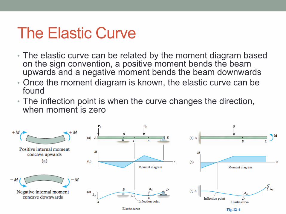
The Elastic Curve • The elastic curve can be related by the moment diagram based
on the sign convention, a positive moment bends the beam upwards and a negative moment bends the beam downwards
• Once the moment diagram is known, the elastic curve can be found
• The inflection point is when the curve changes the direction, when moment is zero

Moment-curvature relationship • The relationship between the internal moment and the radius of
curvature ρ • The analysis is limited to a initially straight beam and elastically
deformed by loads applied perpendicular to the beam. • The deformation is caused by both the internal shear force and
bending moment

Moment-curvature relationship • The internal moment M deforms the element and cause the
angle dθ • EI is called the flexural rigidity

Moment-curvature relationship • The internal moment M deforms the element and cause the
angle dθ • EI is called the flexural rigidity

Slope and Displacement by Integration • The elastic curve can be expressed as v = f(x) • For most engineering applications and design codes, the
square of dv/dx is very small, hence the denominator can be ignored.

Slope and Displacement by Integration • For each integration, it requires a constant of integration • If the distributed w is used, require 4 constants • Generally, we start with the internal moment M and only two constants are
required • If there are discontinuity in the moment, several equations are required for each
region of discontinuity

Sign conventions and coordinates

Boundary and Continuity Conditions • We determine the functions for shear, moment,
slope and displacement at the the place where the value of the function is known, this is called the boundary conditions.
• If the elastic curve cannot be expressed using a single coordinate, the continuity conditions must be used


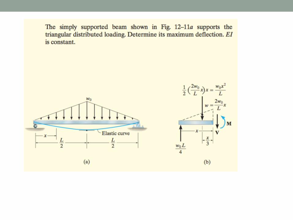
Example