CE 6501 STRUCTURAL ANALYSIS I UNIT V 1. Define stiffness and carry over factor in moment distribution method. [M/J-15] Carry over factor: A moment applied at the hinged end B “carries over” to the fixed end A, a moment equal to half the amount of applied moment and of the same rotational sense. C.O =0.5 Absolute stiffness Absolute stiffness is represented in terms of E, I and L, such as 4EI / L. Relative stiffness Relative stiffness is represented in terms of I and L, omitting the constant E. Relative stiffness is the ratio of stiffness to two or more members at a joint. 2. What is meant by the terms. (a) Moment distribution (b) Distribution factor. [M/J-15] A moment applied at the hinged end B “carries over” to the fixed end A, a moment equal to half the amount of applied moment and of the same rotational sense. C.O =0.5 3. What do you understand by the term distribution factors? [A/M-14,M/J-16] When several members meet at a joint and a moment is applied at the joint to produce rotation without translation of the members, the moment is distributed among all the members
Transcript
CE 6501 STRUCTURAL ANALYSIS I
UNIT V
1. Define stiffness and carry over factor in moment distribution method. [M/J-15]
Carry over factor:
A moment applied at the hinged end B “carries over” to the fixed end A, a moment equal to half
the amount of applied moment and of the same rotational sense.
C.O =0.5
Absolute stiffness
Absolute stiffness is represented in terms of E, I and L, such as 4EI / L.
Relative stiffness
Relative stiffness is represented in terms of I and L, omitting the constant E. Relative
stiffness is the ratio of stiffness to two or more members at a joint.
2. What is meant by the terms.
(a) Moment distribution (b) Distribution factor. [M/J-15]
A moment applied at the hinged end B “carries over” to the fixed end A, a moment equal to half
the amount of applied moment and of the same rotational sense.
C.O =0.5
3. What do you understand by the term distribution factors? [A/M-14,M/J-16]
When several members meet at a joint and a moment is applied at the joint to produce
rotation without translation of the members, the moment is distributed among all the members
meeting at that joint proportionate to their stiffness.
4. What are the conditions in which a frame is subjected to sway? [A/M-12,M J-16]
Eccentric or unsymmetric loading
Unsymmetrical geometry
Different end conditions of the columns
Non-uniform section of the members
Unsymmetrical settlement of supports
A combination of the above
5. A continuous beam ABC of length 2L (with uniform flexural rigidity EI) is simply supported at the ends A and C and continuous over the support B at mid-length. Using moment distribution method, determine the moment at the support B, if it subjected to a uniformly distributed load ‘w’ throughout the length. [N/D-16]
For the above figure the final moments are
MAB; MBA = - MBC; MCB;
6. What is meant by distribution factors. [N/D-16]
When several members meet at a joint and a moment is applied at the joint to produce
rotation without translation of the members, the moment is distributed among all the members
meeting at that joint proportionate to their stiffness.
5. Differentiate between distribution factors and carry over factor. [A/M – 12] Distribution factor:
When several members meet at a joint and a moment is applied at the joint to produce rotation
without translation of the members, the moment is distributed among all the members meeting at
that joint proportionate to their stiffness.
Distribution factor = Relative stiffness / Sum of relative stiffness at the joint
Carry over factor:
A moment applied at the hinged end B “carries over” to the fixed end A, a moment equal to half
the amount of applied moment and of the same rotational sense. C.O =0.5
8. Define point of contra flexure with an example. [A/M - 12, N/D – 13]
In a bending moment diagram, where the sign changes from positive to negative or negative to
positive that place is called point of contra flexure.
9. What is sway correction? Explain. [A/M-12] Sway correction is defined as the removal of lateral movement in the beams or frames by
correction factor is multiplied by corresponding sway moment.
Correction factor =
Nonswayforce
swayforce
10. What is the difference between absolute and relative
stiffness? Absolute stiffness [N/D- 13]
Absolute stiffness is represented in terms of E, I and L, such as 4EI / L.
Relative stiffness
Relative stiffness is represented in terms of I and L, omitting the constant E. Relative
stiffness is the ratio of stiffness to two or more members at a joint.
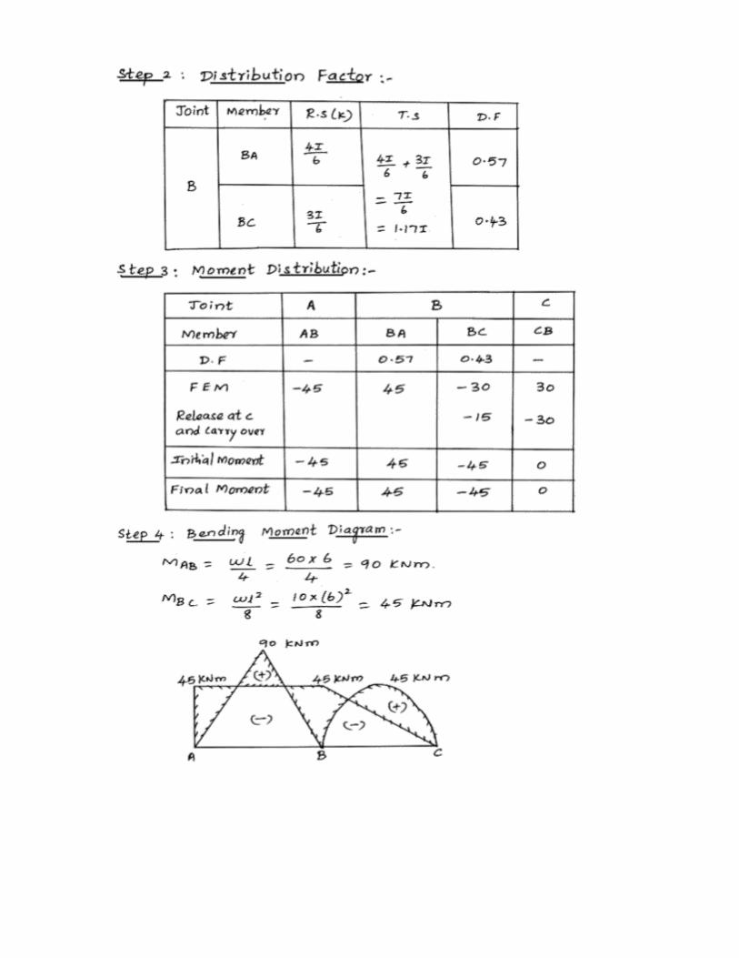
1. (a)(a) Analyze the portal frame shown in Fig. Q. No. 15(a) using moment distribution method.
[M/J-15]
2. (b)Analyze the Continuous beam shown in Fig. Q. No. 15(b) using moment Distribution Method.
[M/J-15,N/D14,A/M-13]
3.(a)A continuous beam ABCDE 18 m long is simply supported at A and also at B. C and D at 74 m, 10 m and 16 m respectively from the left end A and the portion DE being overhanging over 2 m. The span AB carries a point load of 40 kN at its mid-span, the span BC is subjected to a uniformly distributed load of 12 kN/m, the span CD carries a point load of 60 kN at 2 m from C and the free end carries a point load of 10 kN. Analyze the beam by moment distribution method and draw the shearing force and bending moment diagrams. Consider the flexural rigidity for the portions AB, BC and CD, DE as EI, 3EI and 2EI, 2EI respectively. [M/J-16,N/D-14]
4. (b)Analyze the portal frame shown in fig Q.15(b) by moment distribution method and draw the bending moment diagram. Assume flexural rigidity is constant for all the members. [M/J-16]
5. (a)(a) A continuous beam ABC 24 m long is fixed at A, simply supported at B and C. The intermediate support B is at 12 m from A and sinks by 30 mm. The span AB carries a uniformly distributed load,of 3 kN/m and the span BC is subjected to a point load of 24 kN at 8 m from C. Analyze the beam by moment distribution method and draw the shearing force and bending moment diagrams. Take the flexural rigidity EI as 40,000 kNm2 and is constant throughout.[N/D-16,A/M-12,N/D-13]
6. (b)Analyze the frame shown in Fig. Q.15 (b) by moment distribution method uding Naylor’s simplification and draw the bending moment diagram. [N/D-10,A/M-13,N/D-16]


![Hungary [2l]](https://static.documents.pub/doc/80x56/5583e360d8b42aaa5a8b4cf4/hungary-2l.jpg)


