(This is a sample cover image for this issue. The actual cover is not yet available at this time.) This article appeared in a journal published by Elsevier. The attached copy is furnished to the author for internal non-commercial research and education use, including for instruction at the authors institution and sharing with colleagues. Other uses, including reproduction and distribution, or selling or licensing copies, or posting to personal, institutional or third party websites are prohibited. In most cases authors are permitted to post their version of the article (e.g. in Word or Tex form) to their personal website or institutional repository. Authors requiring further information regarding Elsevier’s archiving and manuscript policies are encouraged to visit: http://www.elsevier.com/copyright
Transcript
(This is a sample cover image for this issue. The actual cover is not yet available at this time.)
This article appeared in a journal published by Elsevier. The attachedcopy is furnished to the author for internal non-commercial researchand education use, including for instruction at the authors institution
and sharing with colleagues.
Other uses, including reproduction and distribution, or selling orlicensing copies, or posting to personal, institutional or third party
websites are prohibited.
In most cases authors are permitted to post their version of thearticle (e.g. in Word or Tex form) to their personal website orinstitutional repository. Authors requiring further information
regarding Elsevier’s archiving and manuscript policies areencouraged to visit:
Geological and geomechanical models of the pre-landslide volcanic edifice of Güímarand La Orotava mega-landslides (Tenerife)
J. Seisdedos a,d, M. Ferrer b, L.I. González de Vallejo a,c,d,⁎a Prospección y Geotecnia S.L., Madrid, Spainb Área de Investigación en Peligrosidad y Riesgos Geológicos, Instituto Geológico y Minero de España (IGME), Madrid, Spainc Departamento de Geodinámica, Universidad Complutense de Madrid (UCM), Madrid, Spaind Instituto Volcanológico de Canarias (INVOLCAN), Puerto de la Cruz, Tenerife, Canary Islands, Spain
a b s t r a c ta r t i c l e i n f o
Article history:Received 1 August 2011Accepted 8 June 2012Available online 17 June 2012
Keywords:Volcanic landslidesGeomechanical modelsGüímar and La Orotava mega-landslidesTenerifeCanary Islands
The geological and geomechanical characterizations of the volcanic rock mass succession affected by theGüímar and La Orotava mega-landslides (Tenerife, Canary Island) are presented here for the first time. Theestimated subaerial volume of rocks mobilized by each of these landslides is in the range of 30–50 km3,one of the largest known in the world. Field data, gallery surveys and borehole drilling have allowed themain types of materials and their structural arrangement to be identified. Based on these information a geo-logical model of the pre-landslide volcanic edifice is proposed. A palaeo-morphological reconstruction hasbeen produced and possible slope angles and heights of the pre-landslide volcanic edifice are presented.Five main lithological units have been identified in the emerged part of the edifice, three of them formingthe flanks and two forming the structural axis of the island. On the flanks, lava flows predominate with dif-ferent degrees of alteration and proportion of dikes increasing near the structural axis. The predominant ma-terials on the structural axis are pyroclastic deposits, lava flows and dikes. In the submarine edifice four mainlithological units have been distinguished, formed by hyaloclastites, pillow-lavas, dikes and gravitational de-posits (slope and basin facies). The geomechanical characterization of these materials has been obtained fromfield data, boreholes, laboratory tests and literature review. The geological and geomechanical modelsobtained provide the fundamental basis for the explanation of the instability processes that generated theGüímar and La Orotava mega-landslides.
Many of the world's volcanoes have suffered large gravitationallandslides on their flanks during their geological history. These insta-bility processes are related to the rapid growth of the volcanic edificesand are part of their natural evolution. The occurrence of these pro-cesses on volcanic island flanks has been investigated in the HawaiianRidge (Moore, 1964; Duffield et al., 1982; Lipman et al., 1988; Mooreet al., 1989, 1994; Morgan et al., 2003), La Réunion (Chevallier andBachelery, 1981; Duffield et al., 1982; Lénat et al. 1989; Labazuy,1996; Ollier et al., 1998; Bret et al., 2003; Merle and Lénat, 2003;Oehler et al., 2004, 2005), Lesser Antilles (Roobol et al., 1983;Boudon et al., 1984; Semet and Boudon, 1994; Mattioli et al., 1995;Deplus et al., 2001), Ritter Island and Bismarck Ridge (Johnson,1987), Tristan da Cunha (Holcomb and Searle, 1991), the CanaryIslands (Holcomb and Searle, 1991; Watts and Masson, 1995; TeideGroup, 1997; Urgeles et al., 1997, 1998; Krastel et al., 2001; Masson
et al., 2002; Acosta et al., 2003), Stromboli (Pasquaré et al., 1993;Kokelaar and Romagnoli, 1995; Tibaldi, 1996, 2001; Apuani et al.,2005a, 2005b), French Polynesia (Wolfe et al., 1994; Clément et al.,2002; Clouard and Bonneville, 2004), Cape Verde (Elsworth andDay, 1999; Masson et al., 2008), Ischia (Chiocci and Alteriis, 2006)or Vulcano island (Tommasi et al., 2007). The flanks of volcanic edi-fices may fail and slide in the last phases of their growth when theyreach critical dimensions or when specific triggering factors occur,e.g. large explosive eruptions with associated seismicity (Voight andElsworth, 1997; Tibaldi, 2001). When the materials from the mega-landslides fall into the sea, extensive debris avalanches are depositedon the seabed.
In the Canaries at least ten large palaeo-landslides have occurredover the last 1.5 million years (Krastel et al., 2001; Masson et al.,2002; Acosta et al., 2003; Fig. 1). The landslides which caused theGüímar and La Orotava valleys, on the NE side of the island of Tenerife,are two exceptional cases. The valleys are both “U”-shaped depressions,10 km wide, bounded by impressive vertical scarps (500–600 m high)(Fig. 2). The landslides that generated these valleys, during the Pleisto-cene, mobilized a subaerial volume of rocks in the range of 30–50 km3.However, although these landslides are among the largest in the world
Journal of Volcanology and Geothermal Research 239–240 (2012) 92–110
⁎ Corresponding author at: Universidad Complutense de Madrid (UCM), AntonioNovais 2, 28040 Madrid, Spain. Tel.: +34 913502007; fax: +34 913503876.
Contents lists available at SciVerse ScienceDirect
Journal of Volcanology and Geothermal Research
j ourna l homepage: www.e lsev ie r .com/ locate / jvo lgeores
Author's personal copy
by volume, their causes and failure mechanisms are still not fullyunderstood.
In the last years, engineering geological and rock mechanicalmethods have been applied to the study of instability processes onthe flanks of volcanic edifices with considerable success (Paul et al.,1987; Elsworth and Voight, 1995; Iverson, 1995; Hürlimann, 1999;Reid et al., 2001; Concha-Dimas, 2004; Zimbelman et al., 2004;Apuani et al., 2005a, 2005b; Moon et al., 2005; Schiffman et al.,2006; Van Berlo, 2006, 2007; Thompson et al., 2008). The methodsand software for stability analysis (limit equilibrium or stress–strainmethods), traditionally used in slope stability analysis, provide rele-vant information on the influence of the factors involved in the insta-bility processes (conditioning and triggering factors) and thecharacteristics of the failure mechanisms. For this type of analysis,geological and geomechanical models representative for the pre-landslide volcanic edifices are needed. These models have to considerthe distribution, characteristics and geomechanical properties of thelithological units of the volcano affected by the landslide, as well asits original geometry and hydrogeological conditions. Therefore theresults of the subsequent stability analysis depend largely on the va-lidity and reliability of these models.
The first models for the analysis of instability processes of volcanoflanks were very simple (Paul et al., 1987; Elsworth and Voight, 1995;Iverson, 1995; Hürlimann, 1999). They only distinguished a singlelithological unit and their geomechanical properties were taken
from generic theoretical data. Later, attention was focused on theanalysis of the condition of the materials forming the flanks (Reid etal., 2001) and on the study of the physical and mechanical propertiesof the volcanic materials using rock mechanic methods (Watters etal., 2000; Concha-Dimas, 2004; Zimbelman et al., 2004). More recentinvestigations have pointed out the importance of differentiating andcharacterizing specific lithological units, and establishing the struc-tural distribution of the geological model (Okubo, 2004; Apuaniet al., 2005a, 2005b; Moon et al., 2005; Schiffman et al., 2006; VanBerlo, 2006; Del Potro and Hürlimann, 2008; Thompson et al.,2008). Table 1 shows a summary of the different geological modelsproposed by different authors and their most relevant characteristics.
This paper presents the results of the geological and geo-mechanical investigations carried out on the volcanic rock mass suc-cession involved in the paleo-landslides of Güímar and La Orotavaand the representative models obtained. These models are funda-mental for the stability analysis of the flanks of the volcanic edificesand to determine the causes and failure mechanisms of these mega-landslides.
2. Geological setting
Tenerife is the largest island of the Canaries (2034 km2) and alsowhere the maximum height is reached (3817 m, Teide volcano). Itsvolcanic activity began in the late Miocene, around 12 Ma ago. The
Fig. 1. Large landslide deposits on the submarine flanks of the Canary Islands. Debris avalanches in El Hierro (Hi): El Golfo (1), El Julán (2), Las Playas I, II (3, 4); La Palma (LP): SantaCruz (5), Playa de la Veta complex (6), Cumbre Nueva (7); Tenerife (TF): Icod (8), Roques de García (9), La Orotava (10), Güímar (11), Bandas del Sur (12), Anaga (13), Teno (14);Gran Canaria (GC): Roque Nublo (15), Horgazares (16), North west coast (17), North coast (18); Fuerteventura (Fu): East Canary Ridge (19), Jandia (20). Data from Krastel et al.(2001), Masson et al. (2002) and Acosta et al. (2003). The rectangle indicates the study area where the Güímar and La Orotava valleys are. (UTM 28N/WGS84/Meters).
Fig. 2. View from the NE of the La Orotava valley in Tenerife. This “U”-shaped valley, 10 km wide, that was generated by a large paleo-landslide occurred in the Pleistocene. Thedashed line indicates the boundary of the valley marked by impressive scarps (500–600 m high). In the background is the Teide volcano (3718 m high).
93J. Seisdedos et al. / Journal of Volcanology and Geothermal Research 239–240 (2012) 92–110
Author's personal copy
Table 1Geological and geomechanical models of volcanic edifices in relation to the stability of their flanks including Tenerife geological model proposed in this paper.
Location Geological model Geomechanical properties Referencesb
Several lithological units Sub-aerialstructuralunits
Submarine structural units
Sub-aerial Sub-marine
Differentiatedby the degreeof alteration
Differentiatedby thecomposition
Differentiatedby the degreeof alteration
Differentiatedby thecomposition
Structuralaxis
Flanks Hyaloclastitesandgravitationaldeposits
Pillowlavas
Plutoniccomplex
Watertable
SH X X X 1H X X X X 2H,R (IV) X X X X 3IV X X X X X 4T X X X X 5MR, MH X X X X X X X 6MR X X X X X 7SH, B,O X X X 8C X X X X X X X X 9C X X X X X X X X X 10H X X X X X X X X X X X 11S X X X X X X X X X X 12IV X X X X X X X X X 13P X X X X X X X X X X 14H X X X X X X X X X X 15H X X X X X X X X X X X X 16T X X X X X X X X X X X X X X X 17
a Name of the volcano or island: SH) Mount St. Helens, H) Hawaii, R) Reunion, IV) Idealized volcano, T) Tenerife, MR) Mount Rainer, MH) Mount Hood, B) Bandai, O) Ontake, C) Citlaltepetl, S) Stromboli, P) La Palma.b References: 1). Paul et al., 1987, 2) Iverson, 1995, 3) Elsworth and Voight, 1995, 4) Voight and Elsworth, 1997, 5) Hürlimann, 1999, 6) Watters et al., 2000, 7) Reid et al., 2001, 8) Reid, 2004, 9) Concha-Dimas, 2004, 10) Zimbelman
et al., 2004, 11) Okubo, 2004, 12) Apuani et al., 2005a, 2005b, 13) Oehler et al., 2005, 14) Van Berlo, 2006, 15) Schiffman et al., 2006, 16) Thompson et al., 2008, 17) present research.
94J.Seisdedos
etal./
JournalofVolcanology
andGeotherm
alResearch239
–240(2012)
92–110
Author's personal copy
stratigraphy and chronological relations of the island have been ex-tensively investigated by Fúster et al. (1968), Coello (1973), Abdel-Monem et al. (1972), Ancochea et al. (1990, 1995, 1999) and Martíet al. (1994). The oldest emerged materials appear in the edifices ofRoque del Conde (11.6–6.4 Ma), Anaga (8.0–3.2 Ma) and Teno (7.4–4.5 Ma). They are formed mainly by basalts with some trachytesand phonolites. The subsequent volcanic activity was focused mainlyon two large edifices, Cañadas and Dorsal edifices. The large Cañadasedifice, made up of trachybasalts, phonolites, trachytes and basalts,was built between 3.5 Ma and 0.15 Ma. The Cañadas caldera had sev-eral collapse phases, associated with large ignimbrite emissions. Thisedifice was also affected by large landslides (Tigaiga>2.3 Ma, Roquesde Garcia 0.6–0.7Ma and Icod>0.15 Ma; Cantagrel et al., 1999). Thevolcanic activity in the Dorsal edifice, situated in the eastern part ofthis central caldera, began more than 1 Ma. The Güímar and LaOrotava landslides mainly affected this edifice originating two largedepressions (valleys). The Cañadas caldera depression was later filledby the Teide volcano, which is still active. At the same time a series ofsmall volcanoes erupted at scattered locations throughout the island(Fig. 3).
3. Güímar and La Orotava landslides
The Güímar and La Orotava valleys are both trough-shaped with aflat floor, around 10–11 km wide and long, open seawards and withtheir bisector trending ESE and NNW respectively (Fig. 3). Theheadwalls of these two valleys coincide in correspondence of the NEDorsal, the main volcanic rift zone of the island, also called structuralaxis. In this area the maximum heights of the valleys are reached, in-creasing to the SW between 1700 m and 2400 m. The impressive lat-eral scarps of both valleys, with a mean height of 500 m, reaching600 m at some points, are composed of pre-landslide rocks. Theyare noticeably symmetrical with steep gradients (higher than 30°),which contrast significantly with the gentle slopes of the valley floors,formed by the post-landslide lava flows which filled the depressions.The Güímar and La Orotava valleys affected the Dorsal edifice and, toa lesser extent, the Cañadas edifice (just to the west of La Orotavavalley, Fig. 3). The Dorsal edifice presents a basaltic composition, in
contrast to the mainly acid type volcanism of the Cañadas edifice(Ancochea et al., 1990, 1999).
According to Cantagrel et al. (1999), the estimated age of theGüímar landslide is less than 0.84 Ma, and 0.54–0.69 Ma for LaOrotava landslide. These ages were established using K/Ar techniques(Ibarrola et al., 1993; Ancochea et al., 1995, 1999). Alternatively, new40Ar/39Ar dating results for lava flows lying over the Güímar landslidedeposits, give an age of 1–1.1 Ma (Ferrer et al., 2008; Seisdedos,2008). So that the Güímar landslide occurred more than 1–1.1 Maago, it is earlier than what was stated in previous studies.
Associated to the Güímar and La Orotava landslides there are thedebris avalanche deposits found in the interior of the galleries exca-vated in the valleys (first described by Bravo, 1962). The origin ofthese breccias, made up of a sandy-clay matrix which includes rockblocks of very different composition, size and shape, has been attrib-uted to the Güímar and La Orotava landslides (Navarro and Coello,1989). Fig. 4 shows a geological cross section along the Güímar valley.The location of the landslide deposits that separate pre-landslide andpost-landslide materials can be seen.
A possible sketch of the geological evolution of the area where theGüímar and La Orotava valleys were originated is shown in Fig. 5. Inthe first stage (1) the Dorsal edifice is formed. This early stage ofthe Dorsal edifice is called “Arafo edifice” (Navarro, 2005). In the sec-ond stage (2) the landslide that originated the Güímar valley tookplace, affecting the “Arafo edifice”. (3) A subsequent phase of intensevolcanism of the Dorsal edifice filled the valley depression. The so-called “Cho-Marcial edifice” is formed in this stage (Navarro, 2005).(4) A new instability process took place later generating La Orotavavalley with the landslide that affected the Dorsal and the Cañadas ed-ifices. Finally the depression of La Orotava was filled by materialsfrom new eruptions.
The presence of large masses of landslide (debris avalanche) de-posits lying on the sea bed surrounding the island of Tenerife hasbeen considered as an unquestionable evidence of these large land-slides (Holcomb and Searle, 1991; Watts and Masson, 1995; TeideGroup, 1997; Krastel et al., 2001; Masson et al., 2002; Acosta et al.,2003). According to Acosta et al. (2003) La Orotava submarine debrisavalanche deposits cover an area of approximately 2200 km2, reaching
Fig. 3. Schematic geological map of Tenerife (modified from Ancochea et al., 2004). The rectangle indicates the study area. PS: Pleistocene, PO: Pliocene, MI: Miocene. P: Profilereferred in Fig. 4. D: Outcrop of submarine materials, near the locality of Igueste de San Andrés, where three boreholes were carried out. (UTM 28N/WGS84/Meters).
95J. Seisdedos et al. / Journal of Volcanology and Geothermal Research 239–240 (2012) 92–110
Author's personal copy
as far as 75 km away from the coast, and the submarine deposits fromthe Güímar landslide occupy an area of 2600 km2 reaching a distanceof 85 km from the coast. The volume of these debris avalanches on theocean floor has been estimated to be around 120 km3 in the case ofthe Güímar landslide and less than 500 km3 in the La Orotava landslide(Krastel et al., 2001; Masson et al., 2002). In contrast, the volume ofthese landslides estimated from the valley sizes is much lower, in therange of 30–50 km3. Acosta et al. (2003) propose that the distinctdifference in volume between the inshore and the offshore data isa reflection of the manner in which failures take place along theflanks of volcanoes. They infer that failures in the Canary Islandstook the form described by Jacobs (1995) for the Nuuanu Debris Av-alanche in Oahu, Hawaii. Here failure was in two synchronous ornear synchronous avalanches, one onshore and another offshore.Acosta et al. (2003) further propose that the location of the surfaceseparating these two slip surfaces was controlled by the geology ofthe flank of the volcanoes. They infer that the transition from subaer-ial lavas above to the submarine facies below, a transition marked byvolcaniclastic rocks and glassy lavas (DePaolo et al., 2001), defines
the separation between the slip-planes of the subaerial and subma-rine avalanches.
4. Geological and geomechanical characterizations of the volcanicrock succession
The geological and geomechanical characterizations of the volca-nic rock succession involved in the Güímar and La Orotava landslideshave been carried out from field data obtained in outcrops and galler-ies. These data have been compared and completed with a compre-hensive literature review (Seisdedos, 2008).
4.1. Outcrop characterization
Rock masses forming the lateral and head scarps of the Güímarand La Orotava landslides have been characterized in areas wherepre-landslide volcanic rocks crop out. Because of the difficulty to ac-cess most of these reliefs, field work has been carried out in represen-tative accessible areas (Fig. 6). In situ geomechanical data collection
Fig. 4. Schematic geological cross-section along the Güímar valley corresponding to the P profile (see Fig. 3). G: Cueva de las Colmenas gallery (see Section 4.2).
Fig. 5. Geological evolution approach of Güímar and La Orotava valleys (modified from Navarro, 2004). 1: Early stage of the Dorsal edifice (“Arafo edifice”). 2: Güímar landslide.3: Güímar landslide infill (“Cho-Marcial” edifice). 4: La Orotava landslide.
96 J. Seisdedos et al. / Journal of Volcanology and Geothermal Research 239–240 (2012) 92–110
Author's personal copy
and observation points (marked with an asterisk) can be grouped asfollows:
1 Southern scarp of Güímar (points 1 to 8 and 1*).2 Northern scarp of Güímar (point 2*).3 Eastern scarp of La Orotava (points 9 and 17 to 21).4 Western scarp of La Orotava (points 22 to 26 and 3*).5 Head scarps of Güímar and La Orotava (points 10 to 16).
Table 2 summarizes the lithologies at each point.
In summary, from the field observations the following consider-ations can be established: the more recent or superficial materials for-ming the flanks are mainly massive lava flows and lava flows withscoria layers (Fig. 7A). The presence of pyroclastic deposits anddikes increases towards the inner parts of the flanks and in the struc-tural axis of the island (Fig. 7B). In these areas lava flows have higherdegree of alteration (Fig. 7C, D).
In order to carry out the geomechanical characterization of therock masses, the geomechanical RMR classification (Bieniawski,1989) has been applied in a first approximation. This classification
Fig. 6. Geological map of the study area with geomechanical data collection and observation points.
Table 2Lithologies present in the study outcrops and observation points (marked with an asterisk) (see Fig. 6).
Point Lavaflows
Lava flows withscoria layers
Pyroclasticdeposits
Dikes Point Lavaflows
Lava flows withscoria layers
Pyroclasticdeposits
Dikes Point Lavaflows
Lava flows withscoria layers
Piyoclasticdeposits
Dikes
1 X X X 2* X 19 X2 X X 10 X X 20 X3 X 11 X 21 X4 X 12 X 22 X5 X X 13 X 23 X6 X X X 14 X 24 X7 X X 15 X X X 25 X8 X 16 X 26 X9 X 17 X 3* X1* X 18 X
X Predominant lithologies.* Observation points.
97J. Seisdedos et al. / Journal of Volcanology and Geothermal Research 239–240 (2012) 92–110
Author's personal copy
Fig. 7. Representative views of the volcanic materials observed in some of the outcrops (Fig. 6). A: Lava flows with scoria layers in the exterior parts of the flanks (point 22).B: Pyroclastic deposit succession in the upper part of the structural axis (point 15). C: Highly altered and fractured lava flows in the structural axis (point 16). D: Altered and fracturedlava flows with dikes intrusion in the inner part of the flank (point 5).
Table 3Relative weights of observational and laboratory-determined parameters used to calculate RMR (Bieniawski, 1989).
1. Intact rock strength Point-load Index (MPa) >10 10–4 4–2 2–1Uniaxial compressivestrength, UCS (MPa)
Rating values for each of the five parameters are summed to obtain cumulative RMR value.
98 J. Seisdedos et al. / Journal of Volcanology and Geothermal Research 239–240 (2012) 92–110
Author's personal copy
takes the following geomechanical parameters into account to obtainthe RMR (Rock Mass Rating) quality index: uniaxial compressivestrength of intact rock, degree of fracturing, spacing and conditionsof discontinuities and groundwater conditions (Table 3). The resultsobtained by applying this classification to the lava flows of the geo-mechanical data points are included in Table 4. This classification isnot applicable to pyroclastic deposits and scoria layers. The Geological
Strength Index (GSI) has been also calculated from correspondingchart assigned taking into account the structure and the discontinuitysurface conditions (Hoek et al., 1998) (Section 4.4) and from the RMRvalues by empirical correlation (Hoek and Brown, 1997).
From the obtained data, representative RMR values for relativelyfresh lava flows (F) and altered lava flows (A) have been established.In the case of the fresh ones, it ranges from 56 to 90 (68 mean value)
Table 4Rock Mass Rating (RMR) parameters measured in lava flows at the geomechanical data points (Fig. 6) and derived GSI.
Bold entries: Representative values for relatively fresh lava flows (F) and altered lava flows (A).a The intact rock strength has been determined by field indexes and from Schmidt hammer rebound.b RQD values obtained from correlations with Jv parameter (number of discontinuities per cubic meter) according to the expression RQD=115−3,3Jv.c GSI (Geological Strength Index) calculated from the RMR values by empirical correlation (Hoek and Brown, 1997): GSI=RMR−5 (considering a value of 15 to thewater conditions).
Fig. 8. Galleries excavated in the Güímar and La Orotava valleys. The visited ones are (bold lines): (b) Bolaños, (pm) Pasada de Montelongo, (ps) Pino Soler, (c) Chimoche, (mb)Montaña Blanca, (a) El Aderno, (ba) Barranco de Amance, (d) El Drago, (cc) Cueva de las Colmenas and (sj) San José. 200 m contour intervals. Dashed line: water tablecorresponding to 1985 (previous to the water extractions), with 200 m contour intervals (bold contours every 1000 m) (Consejo Insular de Aguas de Tenerife). (UTM 28N/WGS84/Meters).
99J. Seisdedos et al. / Journal of Volcanology and Geothermal Research 239–240 (2012) 92–110
Author's personal copy
and in the altered lavas from 30 to 66 (47 mean value). GSI values cal-culated from RMR for fresh lava flows range 59–85 (63 mean value)and for altered lava flows 36–61 (50 mean value).
4.2. Galleries
The geological and geomechanical characterizations of the volcanicrocks succession have also been carried out inside several galleries ex-cavated in both valleys. A total of 1051 galleries have been excavatedfor over 170 years in search of groundwater on the island of Tenerife(Balcells, 2007). The galleries are tunnels with a small section(1.8 m2 — the oldest— and around 4 m2 the modern), with rising gra-dients toward the interior of the volcanic edifice (between 5‰ and7‰) and variable length (tens of meters to more than 6 km the lon-gest). Ten are the galleries visited and information of many othershas been consulted. The visited ones are: Cueva de las Colmenas, ElAderno, El Drago, Barranco de Amance and San José in the Güímarvalley; Montaña Blanca, Pasada de Montelongo, Pino Soler, Bolañosand Chimoche in the La Orotava Valley (Fig. 8). The observations
inside the galleries were focused on the aspects of major interest:identification of predominant lithologies, degree of alteration andfracturing, number of dikes intruding the materials, presence ofwater and general geomechanical conditions. Fig. 9 shows the geolog-ical schemes of the volcanic rock successions crossed by these galler-ies. The increase of the degree of alteration and the intrusion ofdykes with depth is shown in this figure.
In summary, from the observations inside the galleries the follow-ing considerations can be advanced. Closer to the gallery pithead re-cent lava flows with scoria layers predominate with low degree ofalteration and compaction. In the scoria layers large cavities areoften developed (Fig. 10A). With depth compaction and alteration in-crease, and scoria layers are no longer identified. Pyroclastic depositscan be also observed (Fig. 10B). The debris avalanche deposits attrib-uted to the landslides are found in many galleries (Fig. 10C, D). Thesedeposits separate post-landslide and pre-landslide materials. Rockslocated deeper are intensely compacted, altered and fractured(Fig. 10E, F). Galleries had to be reinforced in the weaker sections, fre-quently associated with water flow (Fig. 10G). In these areas the pres-ence of dikes is very important (Fig. 10H). Depending on the numberof dikes, three levels of intrusion intensity have been identified: low,with less than 4 dikes per 100 m of gallery length; intense, 4–10 dikesper 100 m; and very intense, with more than 10 dikes per 100 m.
4.3. Hydrogeological conditions
The groundwater galleries excavated in Tenerife provide relevantinformation about the hydrogeological characteristics of the edificesforming the island. The Water Council of Tenerife (Consejo Insular deAguas de Tenerife, CIAT) is the responsible of the water planning andin charge of the hydrogeological data of the galleries of the island. ThisCouncil has also carried out relevant hydrogeological investigations tounderstand the hydrogeological regime of the island (Navarro andFarrujia, 1989). According to the observations carried out in this studyinside the galleries and the data provided by the CIAT, the followingconsiderations can be established. Lithological anisotropies characteris-tic of volcanic materials are directly reflected in the hydrogeologicalbehavior and the groundwater regime. In Tenerife, these anisotropiesare more evident at small scale. For example, along the same gallery,completely dry sections alternate with zones with an important waterflow. These changes in thewater regime are due to the different perme-ability of the materials crossed in the galleries. In general, the more re-cent the rocks, the higher the permeability differences shown, becausethe oldest rocks present a higher degree of compaction. At the scale ofthe whole island, a simplified model can be established with layerscharacterized by permeability decreasing with depth (Fig. 11A), takinginto account the non homogeneity of these layers as mentioned above.This setting is not present in the structural axis or dorsal rift, character-ized by the concentration of volcanic cones at the surface and a densenetwork of dikes associated to an intense fracturing. Both intrusion ofdikes and fracturing change the original characteristics of the rocksand their hydrogeological behavior. Permeability increases due to thepresence of large open fractures and jointed dike networks which oper-ate like effective vertical drainage ways (Figs. 10F, 12). These factorscontribute to establish a vertical intercommunication in the core ofthe structural axis. However, more recent dikes, not affected by fractur-ing, behave as elements of low permeability, making difficult the trans-versal groundwater flow. This creates an anisotropic medium in whichlongitudinal flow (direction of the dorsal rift) is enhanced rather thantransverse flow. As a result the water table is raised and the thick-ness of the saturated zone increases (Fig. 11B).
4.4. Submarine materials
The importance of the submarinematerials in the instability processesof volcanic island flanks was evidenced by DePaolo et al. (2001),
Fig. 9. Geological schemes of the volcanic rocks successions crossed by the galleries inthe La Orotava valley: (c) Chimoche, (b) Bolaños, (ps) Pino Soler, (pm) Pasada deMontelongo, (mb) Montaña Blanca; and the Güímar valley: (sj) San José, (ba) Barrancode Amance, (d) El Drago, (a) El Aderno, (cc) Cueva de las Colmenas. Dike intrusion rate(number of dikes per 100 m of gallery length): low≤4 dikes; intense=4–10 dikes;very intense≥10 dikes. (See location map in Fig. 8).
100 J. Seisdedos et al. / Journal of Volcanology and Geothermal Research 239–240 (2012) 92–110
Author's personal copy
Fig. 10. Representative views of the volcanic materials observed inside the galleries (name of the gallery, distance to the pithead). A: Large cavity formed in a scoria layer (San José,600 m). B: Alternation of pyroclastic deposits (Montaña Blanca, 3400 m). C and D: Landslide deposits (El Drago, 2565 m, and Pasada de Montelongo, 2700 m, respectively). E: Largeopen fracture with water flow (Barranco de Amance, 3125 m). F: Highly altered rocks (Cueva de las Colmenas, 2390 m). G: Reinforcement in jointed and weak sections associatedwith water flow. H: Overlapping dikes (El Drago, 2180 m). (See location map in Fig. 8).
101J. Seisdedos et al. / Journal of Volcanology and Geothermal Research 239–240 (2012) 92–110
Author's personal copy
Schiffman et al. (2006) and Thompson et al. (2008), in the light ofthe Hawaiian Scientific Drilling Project's 3-km-deep drill core. Core sam-ples recovered in such drilling revealed that the upper 1 km of the sub-marine flank of Mauna Kea was composed mainly by hyaloclastites.Strength measurements on this rocks indicated that they were veryweak materials, with mean values for unconfined compressive strengthof 2.5 MPa, 4.6 MPa and 10.0 MPa. The strength of the hyaloclastites in-creased with depth and grade of alteration (the alteration ofhyaloclastites appears to strengthened as opposed to weaken the flanksof the edifice).
In 2006 anoutcrop of submarinematerialswas identified in Tenerife,near the locality Igueste de San Andrés, in the Anaga edifice (Fig. 3),where hyaloclastites with pillow lavas and basaltic dikes crop out(Fig. 13A). In the site three boreholeswere drilled, one of them reaching200m depth. The main lithological units of this borehole are shown inFig. 14. Hyaloclastites are composed of clastic particles of irregularshape and size ranging from 0.5 to 3 cm, forming green, gray or browncolored breccias; many clasts show alteration halos (Fig. 13C). This ma-terial is poorly consolidated and weakly cemented, especially in theshallower parts. Voids and vacuoles are occasionally present withsizes from 0.5 to 3 cm, and secondary minerals are observed insidethem. Fracture zones and slickenside surfaces have been identified(Fig. 13D).
Laboratory tests and in situ pressuremeter tests inside the boreholeswere carried out (e.g., Fig. 13B). The hyaloclastite rocks have lowstrength and high deformability. Uniaxial strength results range from5 MPa to 60MPa, with a mean value of 16 MPa, and pressuremetermoduli range from 5 MPa to 3200 MPa, with a mean representativevalue of 560 MPa (Ferrer et al., 2011a, 2011b).
4.5. Geomechanical properties
Heterogeneity and anisotropy, characteristic of volcanic rocks, arereflected in the variability of their physical and mechanical proper-ties. The collection of geotechnical data in volcanic environments isparticularly difficult because of the geological complexity and the lo-gistical difficulties that often limit the feasibility and reliability ofsampling and carrying out in-situ surveys. For these reasons, inorder to characterize the geomechanical properties of the rockmasses and obtain representative ranges, the data collected fromfield survey and in situ observation were complemented with infor-mation from a comprehensive literature review and subsequent anal-ysis. The analysis is focused on the properties needed for theapplication of Hoek and Brown criterion (Hoek et al., 2002, and refer-ences therein): unit weight (γ), uniaxial compressive strength (σci)and Geological Strength Index (GSI). (Hoek–Brown criterion is ap-plied in Section 5 in order to obtain the strength properties of therock masses.)
Fig. 11. Schematic hydrogeological cross section of Tenerife (modified from Navarroand Farrujia, 1989). Dashed line: water table (WT), solid line: sea level (SL). A: Theo-retical hydrogeological model with lava layers associated to a decreasing permeabilitywith depth. B: Layer model across a structural axis where the water table is raised be-cause of the dikes influence. In the structural axis core, large open fractures, jointeddikes and generalized fracturing contribute to increase the permeability and to estab-lish vertical communication.
Fig. 12. Detail of the geological and hydrogeological data obtained from Cueva de las Colmenas gallery. It can be observed that the water is especially associated with fractures anddikes (see location map in Fig. 8 and cross-section in Fig. 4).
Fig. 13. A: Outcrop of submarine materials located in Tenerife, near Igueste de SanAndrés (see Fig. 3). Pillow lavas and hyaloclastites can be distinguished. B: Uniaxialcompression test on a hyaloclastites core sample. These rocks have low strength withminimum values of 5 MPa. C: Hyaloclastite core samples composed of clastic particlesforming breccias. D: Slickenside surface in a hyaloclastite core sample.
102 J. Seisdedos et al. / Journal of Volcanology and Geothermal Research 239–240 (2012) 92–110
Author's personal copy
In the case of the unit weight and the uniaxial compressivestrength a statistical analysis has been performed taking into accountpublished data. The results are represented in Figs. 15 and 16. Thegraphs include extreme and mean values of the examined literature(references bellow as further detailed), and the mean and most rep-resentative values selected in this study. In the case of the GeologicalStrength Index (GSI), field observations are considered the most rep-resentative data (Fig. 17), but it has been also represented along withother bibliographic results for comparison (Fig. 18).
4.5.1. Unit weightFig. 15 shows the characteristic unit weight values of the volcanic
materials here considered. The data correspond to massive lava flows(Okubo, 2004; Apuani et al., 2005a, 2005b; González de Vallejo et al.,2006, 2008; Hernández et al., 2006; Van Berlo, 2006; Del Potro andHürlimann, 2007, 2008), scoria layers (Apuani et al., 2005a, 2005b;Van Berlo, 2006; Del Potro and Hürlimann, 2007, 2008), altered lavaflows (Reid et al., 2000, 2001; Zimbelman et al., 2003, 2004;Concha-Dimas, 2004; Van Berlo, 2006; Del Potro and Hürlimann,2007, 2008), pyroclastic deposits (IGME, 1974; Peiró, 1997; Serranoand Olalla, 1998; Alvarado, 2003; Sigarán, 2003; Concha-Dimas,2004; Apuani et al., 2005a, 2005b; González de Vallejo et al., 2006,2008; Lomoschitz et al., 2006; Serrano et al., 2007), dikes (Moore,2001; Yokose and Lipman, 2004; Van Berlo, 2006), hyaloclastites(Moore, 2001; Yokose and Lipman, 2004) and pillow lavas (Moore,2001). The most representative values selected have been obtainedconsidering the lower, upper and mean values. Representative unitweight ranges and means (in brackets) are: 19–27 (24) kN/m3 formassive lava flows, 13–16 (15) kN/m3 for scoria layers, 15–19 (17)kN/m3 for altered lava flows, 10–14 (12) kN/m3 for pyroclasticdeposits, 27–30 (28) kN/m3 for dikes, 22–26 (24) kN/m3 forhyaloclastites and 27–29 (28) kN/m3 for pillow lavas (in the case ofdikes, hyaloclastites and pillow lavas, the unit weight is saturated).
values of the volcanic materials. The data correspond to massivelava flows (Thomas et al., 2004; Apuani et al., 2005a, 2005b;González de Vallejo et al., 2006, 2008; Hernández et al., 2006; VanBerlo, 2006; Del Potro and Hürlimann, 2007, 2008), scoria layers(Apuani et al., 2005a, 2005b; Del Potro and Hürlimann, 2007, 2008;Rodríguez-Losada et al., 2007), altered lava flows (Zimbelman et al.,2003, 2004; Concha-Dimas, 2004; Del Potro and Hürlimann, 2007,2008), pyroclastic deposits (IGME, 1974; Serrano and Olalla, 1998;González de Vallejo et al., 2006, 2008; Lomoschitz et al., 2006;Serrano et al., 2007), dikes (Van Berlo, 2006), hyaloclastites(Schiffman et al., 2006) and pillow lavas (Schiffman et al., 2006).The most representative values selected in this study, obtained bythe means of the lower, upper and mean values of the literaturevalues, are (mean in brackets): 69–196 (99) MPa for massive lavaflows, 18–122 (33) MPa for scoria layers, 18–56 (34) MPa for alteredlava flows, 1–4 (2) MPa for pyroclastic deposits, 100–250 (175) MPafor dikes, 1–20 (6) MPa for hyaloclastites and 95–270 (144) MPa forpillow lavas.
Fig. 14. Major lithologic units as described from the 200-m deep borehole.Hyaloclastites are predominant with a global fraction of 70% versus massive basalts.
Fig. 15. Unit weight of volcanic materials. 1: Massive lava flows; 2: Scoria layers; 3: Al-tered lava flows; 4: Pyroclastic deposits; 5: Dikes; 6: Hyaloclastites; 7: Pillow lavas(saturated unit weight in the case of 5, 6 and 7). The fine lines and the gray points rep-resent the extreme and the mean values from the reviewed literature (references inthe text). The thick lines and the large black points represent the representative rangesand means selected in this study.
Fig. 16. Uniaxial compressive strength of volcanic materials (logarithmic scale).1: Massive lava flows; 2: Scoria layers; 3: Altered lava flows; 4: Pyroclastic deposits;5: Dikes; 6: Hyaloclastites; 7: Pillow lavas. The fine lines and the gray points representthe extreme and the mean values of the reviewed literature (references in the text).The thick lines and the large black points represent the representative ranges andmeans selected in this study.
103J. Seisdedos et al. / Journal of Volcanology and Geothermal Research 239–240 (2012) 92–110
Author's personal copy
4.5.3. Geological Strength Index (GSI)Fig. 17 shows the results of applying Geological Strength Index
classification (Hoek et al., 1998) to the volcanic materials involvedin Güímar and La Orotava landslides observed in the outcrops andgalleries. The GSI values obtained from RMR values (Table 1) havebeen also considered. GSI for submarine materials has been obtainedfrom the Igueste de San Andrés outcrop, in the case of hyalocastites;for the pillow lavas the GSI has been estimated and extrapolatedfrom similar outcrops in La Palma island. Obtained GSI ranges andmeans are: 53–71 (63) for massive lava flows, 20–30 (25) for scorialayers, 40–55 (50) for altered lava flows, 15–25 (20) for pyroclasticdeposits, 57–73 (65) for dikes, 17–32 (21) for hyaloclastites and50–70 (63) for pillow lavas. In Fig. 18 these results are compared tothose obtained by other authors for each material: massive lavaflows (Concha-Dimas, 2004; Apuani et al., 2005a, 2005b; Van Berlo,2006; Del Potro and Hürlimann, 2007, 2008; Thompson et al.,
2008), scoria layers (Serrano and Olalla, 1998; Apuani et al., 2005a,2005b; Del Potro and Hürlimann, 2008), altered lava flows (Concha-Dimas, 2004; Del Potro and Hürlimann, 2007, 2008), pyroclastic de-posits (Serrano and Olalla, 1998; Apuani et al., 2005a, 2005b), dikes(Van Berlo, 2006), hyaloclastites (Schiffman et al., 2006; Thompsonet al., 2008) and pillow lavas (Thompson et al., 2008).
Table 5 summarized the most representative geomechanical prop-erties obtained for the different volcanic rock types.
5. Geological model of the pre-landslide volcanic edifice
A morphological reconstruction of the pre-landslide edifice wascarried out from current geomorphological data from the valleyslopes not affected by landslides and from the Dorsal edifice. An esti-mated height of 3500 m a.s.l. was considered, with slopes rangingfrom 12° to 20° in the emerged part of the edifice, while in the
Fig. 17. Geological Strength Index (GSI) of the rock masses grouped into lithological units. Classification table from Hoek et al. (1998). 1: Massive lava flows; 2: Scoria layers;3: Altered lava flows; 4: Pyroclastic deposits; 5: Dikes; 6: Hyaloclastites; 7: Pillow lavas.
104 J. Seisdedos et al. / Journal of Volcanology and Geothermal Research 239–240 (2012) 92–110
Author's personal copy
submarine edifice the slopes range from 3° to 19°, with a maximum esti-mated depth of 2500 m, according to the present seabed depth. The lith-ological units forming the emerged edifice have been defined fromoutcrop data and observations inside the galleries, while the lithologicalunits of the submarine edifice were assessed from boreholes and pub-lished data. The hydrogeological conditions of the pre-landslide edifice
were assumed to be similar to those existing in the island before intensiveexploitation of the aquifers (Fig. 8). According to the available data of theInsular Water Council of Tenerife, the depth of the water table has beenestimated at 600–700 m below the surface, except in areas nearest thecoast. In the central part of the edifice (structural axis) the water table ishigher due to the presence of a large number of dikes (see Section 4.3).
In the following sections we describe the characteristics of thegeological model, including both the emerged and submarine volca-nic materials (Fig. 19).
5.1. Emerged edifice volcanic materials
Thematerials on the flanks of the emerged edifice are different fromthose forming the structural axis. The flanks are formed by deposits out-poured from the eruptive centers of the structural axis, mainly lavaflows with scoria layers whose degree of alteration and compaction in-creases with depth. In the inner part of the flanks, as approaching to thestructural axis, dike intrusion is more intense while it decreases withthe distance from the axis. The structural axis is 3–6 kilometer wideand is characterized by a dense network of dikes, associated with in-tense fracturing and alteration. There is a significant presence of pyro-clastic deposits and lava flows with scoria layers and dikes. Thenumber of dikes and the intrusion density observed in the gallerieshave been considered to characterize the different units, according tothe classification previously established (very intense intrusion, morethan 10 dikes per 100 m of gallery length; intense, 4–10 dikes per100 m; low, less than 4 dikes per 100 m). Some strength propertiesand alteration characteristics of the rock masses have been influenced
Fig. 18. Geological Strength Index (GSI) of volcanic materials. 1: Massive lava flows;2: Scoria layers; 3: Altered lava flows; 4: Pyroclastic deposits; 5: Dikes; 6: Hyaloclastites;7: Pillow lavas. The fine lines and the gray points represent the extreme and meanvalues of the reviewed literature (references in the text). The thick lines and thelarge black points represent the representative ranges and mean values selected inthis study from field observations and data (Fig. 17).
Table 5Geomechanical indexes and properties of volcanic rocks (means in brackets).
Fig. 19. Geological model representing the pre-landslide volcanic edifice across the Dorsal edifice of Tenerife (Fig. 3). WT = water table. SL = sea level. SA = structural axis.
Table 6Rocks materials forming the lithological units in the emerged edifice of Tenerife(Fig. 19).
105J. Seisdedos et al. / Journal of Volcanology and Geothermal Research 239–240 (2012) 92–110
Author's personal copy
by hydrological processes, therefore the water table depth has beentaken into account to assess different degrees of alteration,making pos-sible the distinction of different lithological units. Table 6 shows the ap-proximate percentages, by volume, of the different rockmasses formingthe lithological units of the emerged pre-landslide edifice, flanks andstructural axis (Fig. 19). These units are described below.
• Unit 1: Recent lava flows with scoria layers, showing a low degreeof alteration and layers of loose scoria and cavities.
• Unit 2: Slightly altered lava flows with scoria layers, with a lowerpresence of cavities than Unit 1.
• Unit 3: Altered lava flows and highly compacted pyroclastic de-posits with intense dike intrusion. Depending on the dike intrusiondensity two sub-units have been differentiated (3a and 3b), withUnit 3b showing higher density of dike intrusion.
• Unit 4: Pyroclastic deposits and lava flows with scoria, and intensedike intrusion. This unit presents lower alteration, compaction anddike intrusion density than Unit 5.
• Unit 5: Pyroclastic deposits and altered lavaflows, showing very intensedike intrusion. These materials are highly compacted and fractured.
5.2. Submarine edifice volcanic materials
Most of the information about submarine materials has beenobtained from boreholes drilled in the area and a review of the rele-vant literature (Staudigel and Schmincke, 1984; Nielson and Stinger,1996; Schmincke and Sumita, 1998, 2010; DePaolo et al., 2001;García and Davis, 2001). Table 7 shows the percentages of the differ-ent types of materials forming the submarine lithological units(Fig. 19) which are described below.
• Unit 6: Hyaloclastite rocks, originated from subaerial flows whichformed ‘lava deltas’ entering the sea, as well as originated from sub-marine eruptions. This unit is also composed of pillow lavas. Thethickness of this unit has been estimated in 800 m (Staudigel andSchmincke, 1984; DePaolo et al., 2001; García and Davis, 2001).Two subunits have been differentiated depending on the dike intru-sion and the distribution of these materials in the volcanic edifice.
• Unit 7: Pillow-lavas formed by submarine eruptions, representingthe main submarine growth phase of the island. In the same waythan Unit 6, two subunits have been differentiated.
• Unit 8: Gravitational deposits formed by gravitational and sedimen-tary processes on the submarine flanks. This unit includes slope fa-cies, formed by the slides occurred throughout the growth of theisland, and basin facies, composed of interbedded distal turbidites,fallout tephra layers and hemipelagic sediments.
• Unit 9:Dikes and plutonic complex. These volcanic complexes, knownas the Basal Complexes, crop out in other Canaries (La Palma, LaGomera and Fuerteventura) are composed of a set of submarine andplutonic rocks intensely transversed by a dyke swarm, representingthe submarine growing stage of the island and the roots (plutonsand dikes) of the successive subaerial growing episodes.
6. Geomechanical model of the pre-landslide volcanic edifice
Representative geomechanical parameters of the lithological unitsof the geological model are necessary to carry out any stability
analysis and geomechanical modeling. Strength properties, such ascohesion (c′) and friction (Φ′), are necessary since most geotechnicalsoftware is developed in terms of the Mohr–Coulomb failure criteri-on. However c′ and Φ′ for rock masses cannot be directly measuredor determined in-situ, and “equivalent” parameters must be derivedfrom intact rock properties (e.g. σci) and rock mass quality indexes(e.g. GSI). In this sense, the application of Hoek–Brown criterion(Hoek et al., 2002, and references therein) has been widely used todetermine c′ and Φ′ values of volcanic rock masses (Watters et al.,2000; Concha-Dimas, 2004; Okubo, 2004; Thomas et al., 2004; Apuaniet al., 2005a, 2005b; Moon et al., 2005; Thompson et al., 2008).
Here, the Hoek–Brown criterion (Hoek et al., 2002) has been appliedto estimate the strength parameters of the rockmasses of the geologicalmodel, using the RocLab software (www.rockscience.com). Equivalentcohesion (c′) and friction angle (Φ′) were calculated from the input pa-rameters: uniaxial compressive strength of intact rock constituting therock mass (σci), the Geological Strength Index (GSI), the material con-stant mi depending on the textural and petrographical characteristicsof the intact rock, and the assumed confining pressure (σ3max). The gen-eralized Hoek–Brown criterion is expressed as:
σ ′1 ¼ σ ′
3 þ σ ci mbσ ′
3
σ ′ci
þ s
!a
where σ′1 and σ′3 are the major and minor effective principalstress at failureσci is the uniaxial compressive strength of the intact rock materialmb is a reduced value of the material constant mi and is given by:
mb ¼ mi expGSI−10028−14D
� �
s and a are constants for the rock mass given by the following rela-tionships:
s ¼ expGSI−1009−3D
� �
a ¼ 12þ 16
e−GSI=15−e−20=3� �
:
D is a factor which depends upon the degree of disturbance towhich rock mass has been subjected. In this case the lithologicalunits of the model were regarded as undisturbed (D=0).
The state of stress at failure is then plotted on a σ′1–σ′3 stress di-agram and the equivalent Mohr–Coulomb strength parameters, fric-tion angle Φ′ and cohesive strength c′, calculated for each rock massand confining stress range. This is done by fitting an average linear re-lationship to the curve generated by solving the generalized Hoek–Brown equation for a range of minor principal stress values definedby σtbσ′3bσ′3max. The value of σ′3max, the upper limit of the confiningstress over which the relationship between the Hoek–Brown and theMorh–Coulomb criteria is considered, has to be determined for eachindividual case. In this study, it has been considered an elastic stateof stress in which σ3=0,33σ1. So σ′3max was obtained consideringthe maximum vertical stress due to the overlying material loadingfor each lithological unit: σ1=γh, where γ is the unit weight and hthe depth or thickness of the materials (González de Vallejo andFerrer, 2011).
The input data for each lithological unit were determined based onthe proportions of the different types of materials (Tables 6 and 7)and their properties (Table 5). To estimate a representative value ofσ′ci for each lithological unit, taking into account their different
Table 7Rock materials forming the lithological units in the submarine edifice of Tenerife(Fig. 19).
Lithological units Hyaloclastites Pillow-lavas Dikes
6a 70% 30% –
6b 65% 25% 10%7a 10% 90% –
7b 5% 85% 10%9 – 5% 95%
106 J. Seisdedos et al. / Journal of Volcanology and Geothermal Research 239–240 (2012) 92–110
Author's personal copy
lithological proportions, Laubscher's (1984) criterion was applied. Thiscriterion states σ′ci according to an average of % of the strong rock σci,given by the % of weak rock and the ratio of weak rock σci and strongrock σci.
Table 8 presents the input parameters and the representative rockmass strength values, c′ and Φ′, obtained for the geomechanicalmodel applying the Hoek–Brown criterion.
For the island flanks, where lava flows predominate and both thedegree of alteration and the dike intrusion intensity increase withdepth, the characteristic range of the strength values obtained forthe lithological units is: c′=0.9–2.9 MPa and Φ′=24–51°. For thestructural axis, with a significant presence of pyroclastic depositsand very heavy alteration and intrusion below the water table, thecharacteristic strength values are c′=0.9–2.6 MPa and Φ′=21–32°.For the hyaloclastite rocks in the outermost of the submerged flankthe strength values are: c′=0.5–1.7 MPa and Φ′=14–33° (meanvalues: c′=1.0 MPa and Φ′=23°), and for those in the interior ofthe volcanic edifice: c′=1.3–4.4 MPa and Φ′=11–24° (mean values:c′=2.5 MPa andΦ′=17°). For the units that form the core of the vol-canic edifice, constituted by pillow-lavas and dikes: c′>4.5 MPa andΦ′>25°. In the particular case of Unit 8, formed by gravitational de-posits containing hyaloclastite breccias and sediments, the strengthparameters obtained are: c=0.5–1 MPa,Φ=20° and γsat≈20 kN/m3.
7. Discussion
Several limitations and uncertainties are associated with theelaboration of representative geological and geomechanical modelsof volcanic edifices that have been affected by instability processes.It should be taken into account that such research is based on the re-construction of the volcanic edifices starting from the recognition ofwhat remains of them after suffering these processes. In most cases,the analyzed instability processes have taken place a long time ago(several hundreds of thousands of years in the case of the Güímarand La Orotava landslides); however it can be assumed that it is pos-sible to extrapolate data from current conditions. First, it is necessaryto reconstruct the geometry of the pre-landslide edifice, and in somecases, this requires important assumptions. Moreover, for the geo-logical reconstruction, it is necessary to group volcanic materialsinto general lithological units making simplifications and assump-tions, mainly according to their geomechanical properties and be-havior. It is important to know that the contacts between theselithological units are not net lines; they are lithological gradual tran-sitions (hardly representable at the scale of investigation). On theother hand, the definition of the hydrogeological conditions is notsimple; groundwater distribution in oceanic and continental volca-noes is very poorly understood. The geomechanical characterizationis also subject to many uncertainties. As well as those related above
(the fact that the present rock mass properties might represent thepre-landslide properties), the reliability of the geomechanical in-situ surveys is often limited by the geological complexity and the lo-gistical difficulties. In addition to that, the application of empiricalcriteria of rock mechanics (e.g. Hoek–Brown criterion) to obtain geo-mechanical parameters, which cannot be obtained otherwise, in-volves uncertainties and constitutes a limitation. Moreover, whenthe models include the submarine flanks of volcanic edifices the un-certainties are even more. Research on these materials is very limit-ed and little is known about their distribution in depth and theirphysical and mechanical properties.
However, despite these uncertainties and limitations, the geologi-cal and geomechanical models of Tenerife presented in this study arethe most complete and detailed presented up to now. Many geologi-cal, hydrogeological and geomechanical data from outcrops, bore-holes and galleries have been taken into account. These galleries,not existing in most of the world's volcanoes, constitute a uniquesource of observation and data. Moreover we described data alsobased on an extensive and comprehensive literature review. In partic-ular, the properties of volcanic materials presented here (and partic-ularly the most representative values) can be useful for otherresearchers studying volcano flank collapses.
The proposed models have been elaborated with geomechanicalmodeling purposes in order to evaluate the influence of the factors in-volved in the instability processes and understand the causes and fail-ure mechanisms of the landslides that generated the Güímar and LaOrotava valleys, in the same way that it has been done in other volca-noes around the world (Okubo, 2004; Apuani et al., 2005b; Moonet al., 2005; Thompson et al., 2008). Based on the established models,the influence of the triggering factors such as eruptions or earthquakescould be evaluated, considering different scenarios in the stability anal-ysis. In this case, as in Hawaiian landslides (DePaolo et al., 2001;Schiffman et al., 2006; Thompson et al., 2008), hyaloclastites seem tobe a key factor in favoring instability processes because of their charac-teristics and low strength properties (Seisdedos, 2008; Ferrer et al.,2010, 2011a). We infer that a failure mechanism characterized by theoccurrence of successive landslides (whichmay have started in the sub-marine flank, conditioned by the presence of weak and poorly consoli-dated hyaloclastites) could have taken place in the generation of theGüímar and La Orotava valleys (Seisdedos, 2008).
8. Conclusions
This paper presents a geological model representing the islandvolcanic edifice before the pre-historic Güímar and La Orotava land-slides took place. The model has been defined from the analysis of ex-tensive field data particularly those obtained inside the galleries thatrun through the interior of the island.
Table 8Input data for the application of Hoek–Brown criterion and strength equivalent properties obtained for each lithotechnical unit (Fig. 19) with geomechanical modeling purposes(means in brackets).
107J. Seisdedos et al. / Journal of Volcanology and Geothermal Research 239–240 (2012) 92–110
Author's personal copy
To define the possible geometry of the model, the analysis of mor-phological, topographical and bathymetric data was carried out inzones that predate the landslides, to estimate the slope gradientsand maximum heights of the previously existing volcanic edifice.The hydrogeological conditions were also considered, examining thepossible water table depths.
The lithological units which form the geological model were de-fined for both the emerged and the submerged volcanic edifice. Thegeomechanical properties of these units were obtained from boreholedata, site investigations, laboratory tests and the application of empir-ical rock mechanical criteria, and complemented with literature data,to estimate the representative strength parameters for each litholog-ical unit.
Taking into account the large dimensions of the volcanic edificeanalyzed, in the order of 24.5 km in diameter and with an altitudeof 3.5 km (6 km from the ocean bottom), the models are necessarilyschematic, but they represent the geological, hydrogeological andmorphological conditions of the edifice before the Güímar and LaOrotava landslides took place. In spite of simplifications and uncer-tainties, particularly with reference to the submerged edifice, thedata obtained are relevant and representative for the analysis of thestability conditions in which the Güímar and La Orotava mega-landslides occurred. They therefore provide fundamental data andcriteria for the study of the causes and mechanisms of the islandflank failures.
Acknowledgments
This research has been supported by the Spanish Science Ministry,through the National Research Plan I+D, and the Geological Surveyof Spain (IGME) by means of the research project “GRANDETEN”(CGL2004-00899). The authors are very grateful to the participantsof this project who helped and contributed to this research. The con-tributions of J.M. Navarro Latorre and J.J. Coello Bravo are very muchappreciated. Thanks specially to A. Tibaldi for his constructive com-ments on earlier version of the manuscript and another anonymousreviewer, for their contributions to improve this paper.
References
Abdel-Monem, A., Watkins, N.D., Gast, P.W., 1972. Potassium–argon ages, volcanic stra-tigraphy, and geomagnetic polarity history of Canary Islands: Tenerife, La Palma,and Hierro. American Journal of Science 272, 805–825.
Acosta, J., Uchupi, E., Muñoz, A., Herranz, P., Palomo, C., Ballesteros, M., ZEE WorkingGroup, 2003. Geologic evolution of the Canarian Islands of Lanzarote, Fuerteventura,Gran Canaria and La Gomera and comparison of landslides at these island withthose at Tenerife, La Palma and El Hierro. Marine Geophysical Research 24, 1–40.
Alvarado, G.E., 2003. Diagnóstico de la estabilidad del cono y comportamiento de lafundación debido al crecimiento del edificio volcánico del Arenal (Costa Rica).PhD Thesis, Univ. Costa Rica.
Ancochea, E., Fúster, J.M., Ibarrola, E., Cendrero, A., Hernán, F., Cantagrel, J.M.,Jamond, C., 1990. Volcanic evolution of the island of Tenerife (Canary Island) inthe light of new K-Ar data. Journal of Volcanology and Geothermal Research44, 231–249.
Ancochea, E., Huertas, M.J., Fúster, J.M., Cantagrel, J.M., Coello, J., Ibarrola, 1995.Geocronología de la Pared de la Caldera de las Cañadas (Tenerife, Islas Canarias).Boletín de la Real Sociedad Española de Historia Natural 90 (1–4), 107–124.
Ancochea, E., Huertas, M.J., Cantagrel, J.M., Coello, J., Fúster, J.M., Arnaud, N., Ibarrola, E.,1999. Evolution of the Cañadas edifice and its implications for the origin of theCañadas Caldera (Tenerife, Canary Islands). Journal of Volcanology and GeothermalResearch 88, 177–199.
Ancochea, E., Hernán, F., Bellido, F., Muñoz, M., Sagredo, J., Brändle, J.L., Huertas, M.J.,Barrera, J.L., Cubas, C.R., Herrera, R., De laNuez, J., Coello, J., Gómez, J.A., 2004. Canarias.In: Vera, J.A. (Ed.), Geología de España, SGE-IGME, pp. 637–671.
Apuani, T., Corazzato, C., Cancelli, A., Tibaldi, A., 2005a. Physical and mechanical prop-erties of rock masses at Stromboli: a dataset for volcano instability evaluation. Bul-letin of Engineering Geology and the Environment 64, 419–431.
Apuani, T., Corazzato, C., Cancelli, A., Tibaldi, A., 2005b. Stability of a collapsing volcano(Stromboli, Italy): limit equilibrium analysis and numerical modelling. Journal ofVolcanology and Geothermal Research 144, 191–210.
Balcells, R., 2007. Las galerías de agua en Tenerife. Tierra y Tecnología 31, 19–26.Bieniawski, Z.T., 1989. Engineering Rock Mass Classification. Wiley, New York.
Boudon, G., Semet, M.P., Vincent, P.M., 1984. Flank failure-directed blast eruption atSoufrière, Guadeloupe, French West Indies: A 3000-yr-old Mt. St. Helens? Geology12, 350–353.
Bravo, T., 1962. El circo de Las Cañadas y sus dependencias. Boletín de la Real SociedadEspañola de Historia Natural 40, 93–108.
Bret, L., Fevre, Y., Join, J.-L., Robineau, B., Bachelery, P., 2003. Deposits related to degra-dation processes on Piton des Neiges Volcano (Reunion Island): overview and geo-logical hazard. Journal of Volcanology and Geothermal Research 123, 25–41.
Cantagrel, J.M., Arnaud, N.O., Ancochea, E., Fuster, J.M., Huertas, M.J., 1999. Repeateddebris avalanches on Tenerife and genesis of las Cañadas caldera wall (CanaryIslands). Geology 27 (8), 739–742.
Chevallier, L., Bachelery, P., 1981. Evolution structurale du volcan actif du Piton de laFournaise, Ile de la Réunion – Océan indien occidental. Bulletin Volcanologique44–4, 723–741.
Chiocci, F.L., Alteriis, G., 2006. The Ischia debris avalanche: first clear submarine evi-dence in the Mediterranean of a volcanic island prehistorical collapse. Terra Nova18, 202–209.
Clément, J.-P., Legendre, C., Caroff, M., Guillou, H., Cotten, J., Bollinger, C., Guille, G.,2002. Epiclastic deposit and “horse-shaped” calderas in Tahiti (Society islands)and Ua Huka (Marquesas Archipelago), French Polinesia. Journal of Volcanologyand Geothermal Research 120, 87–101.
Clouard, V., Bonneville, A., 2004. Submarine landslides in French Polynesia. In:Hekinian, R., Stoffers, P., Cheminèe, J.L. (Eds.), Oceanic Hotspots. Springer-Verlag,Berlin, pp. 209–238.
Coello, J., 1973. Las series volcánicas en subsuelos de Tenerife. Estudios GeológicosXXVII, 491–512.
Concha-Dimas, A., 2004. Numerical modeling in understanding catastrophic collapse atPico de Orizaba, México. Ph.D. Thesis, Univ. Nevada.
Del Potro, R., Hürlimann, M., 2007. Strength of volcanic rock masses in edifice instabil-ity: insights from Teide, Tenerife. In: Malheiro, A.M., Nunes, J.C. (Eds.), VolcanicRocks. Taylor & Francis Group, London, pp. 175–183.
Del Potro, R., Hürlimann, M., 2008. Geotechnical classification and characterization ofmaterials for stability analyses of large volcanic slopes. Engineering Geology 98,1–17.
DePaolo, D.J., Stolper, E., Thomas, D.M., 2001. Deep drilling into a Hawaiian volcano. Eos82 (13), 149 (154–155).
Deplus, C., Le Friant, A., Boudon, G., Komorowski, J.-C., Villemant, B., Harford, C.,Ségoufin, J., Cheminée, J.-L., 2001. Submarine evidence for large scale debris ava-lanches in the Lesser Antilles Arc. Journal of Volcanology and Geothermal Research192, 145–157.
Duffield, W.A., Stieltjes, L., Varet, J., 1982. Huge landslides blocks in the growth of Pitonde la Fournaise, La Réunion, and Kilauea volcano, Hawaii. Journal of Volcanologyand Geothermal Research 12, 147–160.
Elsworth, D., Day, S.J., 1999. Flank collapse triggered by intrusion: the Canarian andCape Verde Archipielagoes. Journal of Geophysical Research 94, 323–340.
Elsworth, D., Voight, B., 1995. Dike intrusion as trigger for large earthquakes and thefailure of volcano flanks. Journal of Geophysical Research 100, 6005–6024.
Ferrer, M. (coord.), González de Vallejo, L.I., Seisdedos, J., García López-Davalillo, J.C.,Coello Bravo, J.J., Casillas, R., Martín, C. (2008). Peligrosidad de los grandesdeslizamientos en masa de la isla de Tenerife. Análisis geológico y modelizacióngeomecánica de los mecanismos de inestabilidad (“GRANDETEN”), IGME-CICYTCGL2004-00899 project, internal report (unpublished).
Ferrer, M., Seisdedos, J., González de Vallejo, L.I., 2010. The role of hyaloclastite rocks inthe stability of the volcanic island flank of Tenerife. In: Olalla, C., Hernández, L.E.,Rodríguez-Losada, J.A., Perucho, A., González-Gallego, J. (Eds.), Volcanic Rock Me-chanics. Taylor and Francis Group, London, pp. 167–170.
Ferrer, M., González de Vallejo, L.I., Seisdedos, J., Coello, J.J., García López-Davalillo, J.C.,Hernández, L.E., Casillas, R., Martín, C., Rodríguez, J.A., Madeira, J., Andrade, C.,Freitas, M.C., Lomoschitz, A., Yepes, J., Meco, J., Betancort, J.F., 2011a. Güímar andLa Orotava mega-landslides (Tenerife) and tsunami deposits in Canary Islands.Proceedings of the 2nd World Landslide Forum, Rome. 6 pp.
Ferrer, M. (coord.), González de Vallejo, L.I., Seisdedos, J., García López-Davalillo, J.C.,Coello, J.J., Hernández, L.E., Casillas, R., Martín, C., Rodríguez, J.A., Madeira, J.,Andrade, C., Freitas, M.C., Lomoschitz, A., Yepes, J., Meco, J., Betancort, J.F.,(2011b). Estabilidad de los edificios volcánicos en Canarias: Analisis de los fac-tores geologicos, geomecanicos y paleoclimaticos. Aplicacion a los flancos N y Sde la isla de Tenerife. IGME-CICYT CGL2008-01423 project, internal report(unpublished).
Fúster, J.M., Araña, V., Brandle, M., Navarro, M., Alonso, U., Aparicio, A., 1968. Geologyand Volcanology of the Canary Islands. Tenerife. Instituto Lucas Mallada, CSIC,Spain. 218 pp.
García, M.O., Davis, M.G., 2001. Submarine growth and internal structure of ocean is-land volcanoes based on submarine observations of Mauna Loa volcano, Hawaii.Geology 29 (2), 163–166.
González de Vallejo, L.I., Ferrer, M., 2011. Geological Engineering. CRC Press/Balkema,The Netherlands. 978 pp.
González de Vallejo, L.I., Hijazo, T., Ferrer, M., Seisdedos, J., 2006. Caracterizacióngeomecánica de los materiales volcánicos de Tenerife. IGME, Madrid, Spain. 148 pp.
González de Vallejo, L.I., Hijazo, T., Ferrer, M., 2008. Engineering geological propertiesof the volcanic rocks and soils of the Canary Island. Soils and Rocks 31, 3–13.
Hernández, L.E., Rodríguez, J.A., Olalla, C., Perucho, A., Serrano, A., 2006. Estudio decaracterización geotécnica de las rocas volcánicas de las Islas Canarias, AT-SGT-01. Regional Ministry of Public Works. Government of the Canary Islands(unpublished).
Hoek, E., Brown, E.T., 1997. Practical estimates of rock mass strength. InternationalJournal of Rock Mechanics and Mining Sciences 34 (8), 1165–1189.
108 J. Seisdedos et al. / Journal of Volcanology and Geothermal Research 239–240 (2012) 92–110
Author's personal copy
Hoek, E., Marinos, P., Benissi, M., 1998. Applicability of the geological strength index(GSI) classification for very weak and sheared rock masses. The case of the AthensSchist Formation. Bulletin of Engineering Geology and the Environment 57,151–160.
Hoek, E., Carranza-Torres, C.T., Corkum, B., 2002. Hoek–Brown Failure Criterion,2002 edition. Proc. North American Rock Mechanics Society, Toronto, Canada,pp. 267–273.
Holcomb, R.T., Searle, R.C., 1991. Large landslides from oceanic volcanoes. MarineGeotechnology 10, 19–32.
Hürlimann, M., 1999. Geothecnical analysis of large volcanic landslides: The La Orotavaevents on Tenerife, Canary Islands. Ph.D. Thesis, Univ. Técnica de Cataluña.
Ibarrola, E., Ancochea, E., Fúster, J.M., Cantagrel, J.M., Coello, J., Snelling, N.J., Huertas,M.J., 1993. Chronostratigraphy of the Tigaiga massif: Evolution of a sector of theCañadas edifice (Tenerife, Canary Islands). Boletín de la Real Sociedad Españolade Historia Natural 88, 57–72.
IGME, 1974. Mapa geotécnico general, 1:200.000. Hoja 10/10-11/91, Santa Cruz deTenerife.
Iverson, R.M., 1995. Can magma-injection and groundwater forces causse massivelandslides on Hawaiian volcanoes? Journal of Volcanology and Geothermal Re-search 66, 295–308.
Jacobs, C.L., 1995. Mass wasting along the Hawaiian Ridge: giant debris avalanches. In:Pickering, K.T., Hiscott, R.N., Kenyon, N.H., Ricci, R., Smith, R.D.A. (Eds.), Atlas ofDeep Water Environments. : Architectural Style in Turbidite systems. Chapman &Hall, London, pp. 26–28.
Johnson, R.W., 1987. Large-scale volcanic cone collapse: the 1888 slope failure of Rittervolcano, and other examples from Papua New Guinea. Bulletin of Volcanology 49,669–679.
Kokelaar, P., Romagnoli, C., 1995. Sector collapse, sedimentation and clast populationevolution at active island-arc volcano: Stromboli, Italy. Bulletin of Volcanology57, 240–262.
Krastel, S., Schmincke, H.U., Jacobs, C.L., Rihm, R., Le Bas, T.P., Alibés, B., 2001. Subma-rine landslides around the Canary Islands. Journal of Geophysical Research 106,3977–3997.
Labazuy, P., 1996. Recurrent landsliding events on the submarine flank on Piton de laFournaise volcano (Réunion Island). In: McGuire, W.J., Jones, A.P., Neuberg, J.(Eds.), Volcano Instability on the Earth and others Planets: Geological Society ofLondon, 110, pp. 293–306.
Laubscher, D.H., 1984. Design aspects and effectiveness of support systems in differentmining conditions. Transactions of The Institution of Mining and Metallurgy Sec-tion A 93, A70–A81.
Lénat, J.-F., Vicent, P., Bachèlery, P., 1989. The off-shore continuation of an active basal-tic volcano: Piton de la Fournaise (Reunion island, Indian ocean); structural andgeomorphological interpretation from sea beam mapping. Journal of Volcanologyand Geothermal Research 36, 1–36.
Lipman, P.W., Normark, W.R., Moore, J.G., Wilson, J.B., Gutmacher, E., 1988. The giantsubmarine Alika debris slide, Mauna Loa, Hawaii. Journal of Geophysical Research93 (B5), 4279–4299.
Lomoschitz, A., Jiménez, J.R., Yepes, J., Pérez-Luzardo, J.M., Macías-Machín, A., Socorro,M., Hernández, L.E., Rodríguez, J.A., Olalla, C., 2006. Basaltic lapilli used for con-struction purposes in the Canary Islands, Spain. Environmental and EngineeringGeoscience XII (4), 327–336.
Masson, D.G., Watts, A.B., Gee, M.J.R., Urgeles, R., Mitchell, N.C., Le Bas, T.P., Canals, M.,2002. Slope failures on the flanks of the western Canary Islands. Earth-Science Re-views 57, 1–35.
Masson, D.G., Le Bas, T.P., Grevemeyer, L., Weinrebe, W., 2008. Flank collapse and large-scale landsliding in the Cape Verde Islands, off West Africa. Geochemistry, Geo-physics, Geosystems 9, Q07015. http://dx.doi.org/10.1029/2008GC001983.
Mattioli, G.S., Jansma, P.E., Jaramillo, L., Smith, A.L., 1995. Sector collapse in island arcvolcanoes: a digital topographic bathymetric investigation of the Qualibou depres-sion, St. Lucia, Lesser Antilles. Caribbean Journal of Science 31 (3–4), 163–173.
Merle, O., Lénat, J.-F., 2003. Hybrid collapse mechanism at Piton de la Fournaise volca-no, Reunion Island, Indian Ocean. Journal of Geophysical Research 108 (B3). http://dx.doi.org/10.1029/2002JB002014.
Moon, V., Bradshaw, J., Smith, R., de Lange, W., 2005. Geotechnical characterisation ofstratocone crater wall sequences, White Island Volcano, New Zealand. EngineeringGeology 81, 146–178.
Moore, J.G., 1964. Giant submarine landslides on the Hawaiian ridge. USGS Prof. Paper,501-D, pp. D95–D98.
Moore, J.G., 2001. Density of basalt core from Hilo drill hole, Hawaii. Journal of Volca-nology and Geothermal Research 112, 211–230.
Moore, J.G., Clague, D.A., Holcomb, R.T., Lipman, P.W., Normark, W.R., Torresas, M.E.,1989. Prodigious submarine landslides on the Hawaiian ridge. Journal of Geophys-ical Research 94 (B12), 17465–17484.
Morgan, J.K., Moore, G.F., Clague, D.A., 2003. Slope failure and volcanic spreading alongthe submarine south flank of Kilauea volcano, Hawaii. Journal of Geophysical Re-search 108 (B9), 2415.
Navarro, J.M., 2004. Geología de Tenerife. In: García Canseco, V. (Ed.), Parque Nacionaldel Teide. Esfagnos, Spain, pp. 19–72.
Navarro, J.M., March, 2005. Personal communication.Navarro, J.M., Coello, J., 1989. Depressions originated by landslide proceses in Tenerife.
European Science Foundation Meeting on Canarian Volcanism, Lanzarote, Spain,pp. 150–152.
Navarro, J.M., Farrujia, I., 1989. Bases para el planeamiento hidrogeológico insular.Zonificación hidrogeológica. Aspectos geológicos e hidrogeológicos. Cabildo Insularde Tenerife. 145 pp.
Nielson, D.L., Stinger, S.G., 1996. Drilling and evaluation of the Ascencion island, southAtlantic Ocean. Geothermics 25 (4/5), 543–560.
Oehler, J.F., Labazuy, P., Lènat, J.F., 2004. Recurrence of major flank landslides duringthe last 2-Ma-history of Reunion Island. Bulletin of Volcanology 66, 585–598.
Oehler, J.F., van Wyk de Vries, B., Labazuy, P., 2005. Landslides and spreading of oceanichot-spot and arc shield volcanoes on Low Strength Layers (LSLs): an analoguemodelling approach. Journal of Volcanology and Geothermal Research 144,169–189.
Okubo, C.H., 2004. Rock mass strength and slope stability of the Hilina slump, Kilaueavolcano, Hawaii. Journal of Volcanology and Geothermal Research 138, 43–76.
Ollier, G., Cochonat, P., Lénat, J.F., Labazuy, P., 1998. Deep-sea volcaniclastic sedimenta-ry systems : an example from La Fournaise volcano, Réunion island, Indian ocean.Sedimentology 45, 293–330.
Pasquaré, G., Francalanci, L., Garduño, V.H., Tibaldi, A., 1993. Structure and geologicalevolution of the Stromboli volcano, Aeolian islands, Italy. Acta Vulcanologica 3,79–89.
Paul, A., Gratier, J.P., Boudon, J., 1987. A numerical model for simulating deformation oMount St. Helens volcano. Journal of Geophysical Research 92 (B10), 10299–10312.
Peiró, R., 1997. Caracterización geotécnica de los materiales volcánicos del ArchipiélagoCanario. Tierra y Tecnología 16 (17), 45–49.
Reid, M.E., 2004. Massive collapse of volcano edifices triggered by hydrothermal pres-surization. Geology 32 (5), 373–376.
Reid, M.E., Chrisn, S.B., Brien, D.L., 2000. Gravitational stabilitiaty of tree-dimensionalstratovolcano. Journal of Geophysical Research 105 (B3), 6043–6056.
Reid, M.E., Sisson, T.W., Brien, D.L., 2001. Volcano collapse promoted by hydrother-mal alteration and edifice shape, Mount Rainer, Washington. Geology 29 (9),779–782.
Rodríguez-Losada, J.A., Hernández-Gutiérrez, L.E., Olalla, C., Perucho, A., Serrano, A., delPotro, R., 2007. The volcanic rocks of the Canary Islands. Geotechnical properties.In: Malheiro, A.M., Nunes, J.C. (Eds.), Volcanic Rocks. Taylor & Francis Group, London,pp. 53–57.
Roobol, M.J., Wright, J.V., Smith, A.L., 1983. Calderas or gravity-slide structures in theLesser Antilles island arc? Journal of Volcanology and Geothermal Research 19,121–134.
Schiffman, P., Watters, R.J., Thompson, N., Walton, A.W., 2006. Hyaloclastites and theslope stability of Hawaiian volcanoes: Insights from the Hawaiian Scientific Dril-ling Project's 3-km drill core. Journal of Volcanology and Geothermal Research151, 217–228.
Schmincke, H.-U., Sumita, M., 1998. Volcanic evolution of Gran Canaria reconstructedfrom apron sediments: synthesis of VICAP project drilling. In: Weaver, P.P.E.,Schmincke, H.-U., Firth, J.V., Duffield, W. (Eds.), Proc. ODP Sci. Results, 157,pp. 267–292.
Schmincke, H.-U., Sumita, M., 2010. Geological Evolution of the Canary Islands. Görres-Druckerei und Verlag GmbH, Koblenz. 188 pp.
Seisdedos, J., 2008. Los grandes paleo-deslizamientos de Güímar y La Orotava (Tenerife):Análisis geológico, mecanismos de inestabilidad y modelización geomecánica. PhDThesis, Univ. Complutense de Madrid. E-prints Complutense (eprints.ucm.es/8293/).
Semet, M.P., Boudon, G., 1994. Large scale collapse structure at Piton du Carbet, Marti-nique: geological and petrological constraints. Proceedings of International Confer-ence on Volcano Instability on the Earth & Other Planets. Geol. Soc., London.
Serrano, A., Olalla, C., 1998. Propiedades geotécnicas de materiales canarios yproblemas de cimentaciones y estabilidad de ladera en obras varias. III EncuentroNacional de la Carretera, Islas Canarias, pp. 175–212.
Serrano, A., Olalla, C., Perucho, A., Hernández-Gutiérrez, L.E., 2007. Stregth anddeformability of low density pyroclast. In: Malheiro, A.M., Nunes, J.C. (Eds.), Volca-nic Rocks. Taylor & Francis Group, London, pp. 35–43.
Sigarán, C., 2003. Numerical assessment of the influence of earthquakes on irregular to-pographies – Analysis of Colombia, 1999 and El Salvador, 2001 earthquakes. PhDThesis. Delft University.
Staudigel, H., Schmincke, H.-U., 1984. The Pliocene seamount series of La Palma, CanaryIslands. Journal of Geophysical Research 89 (B13), 11195–11215.
Teide Group, 1997. Morphometric interpretation of the northwest and southeastslopes of Tenerife, Canary Islands. Journal of Geophysical Research 102 (B9),20325–20342.
Thomas, M.E., Petford, N., Bromhead, E.D., 2004. Volcanic rock-mass properties fromSnowdonia and Tenerife: implications for volcano edifice strength. Journal of theGeological Society (London, United Kingdom) 161, 1–8.
Thompson, N., Watters, R.J., Schiffman, P., 2008. Stability analysis of Hawaiian Islandflanks using insight gained from strength testing of the HSDP core. Journal of Vol-canology and Geothermal Research 171, 163–177.
Tibaldi, A., 1996. Mutual influence of diking and collapses at Stromboli volcano, AeolianArc, Italy. Geological Society Special Publication, London 110, 55–63.
Tibaldi, A., 2001. Multiple sector collapses at Stromboli volcano, Italy: how they work.Bulletin of Volcanology 63, 112–125.
Tommasi, P., Graziani, A., Rotonda, T., Bevino, C., 2007. Preliminary analysis of instabil-ity phenomena at Vulcano island, Italy. In: Malheiro, A.M., Nunes, J.C. (Eds.), Volca-nic Rocks. Taylor & Francis Group, London, pp. 147–154.
Urgeles, R., Canals, M., Baraza, J., Alonso, B., Masson, D.G., 1997. The most recentmegalandslides of the Canary Islands: El Golfo debris avalanche and Canary debrisflow, west El Hierro Island. Journal of Geophysical Research 102, 20305–20323.
Urgeles, R., Canals, M., Baraza, J., Alonso, B., 1998. Seismostratigraphy of the westernflanks of El Hierro and La Palma (Canary Islands): a record of Canary Islands volca-nism. Marine Geology 146, 225–241.
109J. Seisdedos et al. / Journal of Volcanology and Geothermal Research 239–240 (2012) 92–110
Author's personal copy
Van Berlo, J.M.C., 2006. Massive flank collapse at La Palma. Numerical slope stabilitymodels of the Cumbre vieja volcano. PhD Thesis. Delft University of Technology.
Van Berlo, J., 2007. Simulation of a volcano in Plaxis. Plaxis Bulletin 21, 5–8.Voight, B., Elsworth, D., 1997. Failure of volcano slopes. Geotechnique 47, 1–31.Watters, R.J., Zimbelman, D.R., Bowman, S.D., Crowley, J.K., 2000. Rock mass strength
assessment and significance to edifice stability, Mount Rainer and Mount Hood,Cascade Range volcanoes. Pure and Applied Geophysics 157, 957–976.
Watts, A.B., Masson, D.G., 1995. A giant landslide on the north flank of Tenerife, CanaryIslands. Journal of Geophysical Research 100, 24487–244498.
Wolfe, C.J., McNutt, M.K., Detrick, R.S., 1994. The Marquesas archipelagic apron: seismicstratigraphy and implications for volcano growth, mass wasting, and crustalunderplating. Journal of Geophysical Research 99, 13591–13608.
Yokose, H., Lipman, P.W., 2004. Emplacement mechanisms of the South Kona slidecomplex, Hawaii island: sampling and observations by remotely operated vehicleKaiko. Bulletin of Volcanology 22, 569–584.
Zimbelman, D.R., Watters, R.J., Bowman, S., Firth, I.R., 2003. Quantifying hazards andrisk assessments at active volcanoes. Eos 84 (23), 213–224.
Zimbelman, D.R., Watters, R.J., Firth, I.R., Breit, G.N., Carrasco-Nunez, G., 2004. Strato-volcano stability assessment methods and results from Citlaltépetl, Mexico. Bulle-tin of Volcanology 66, 66–79.
110 J. Seisdedos et al. / Journal of Volcanology and Geothermal Research 239–240 (2012) 92–110


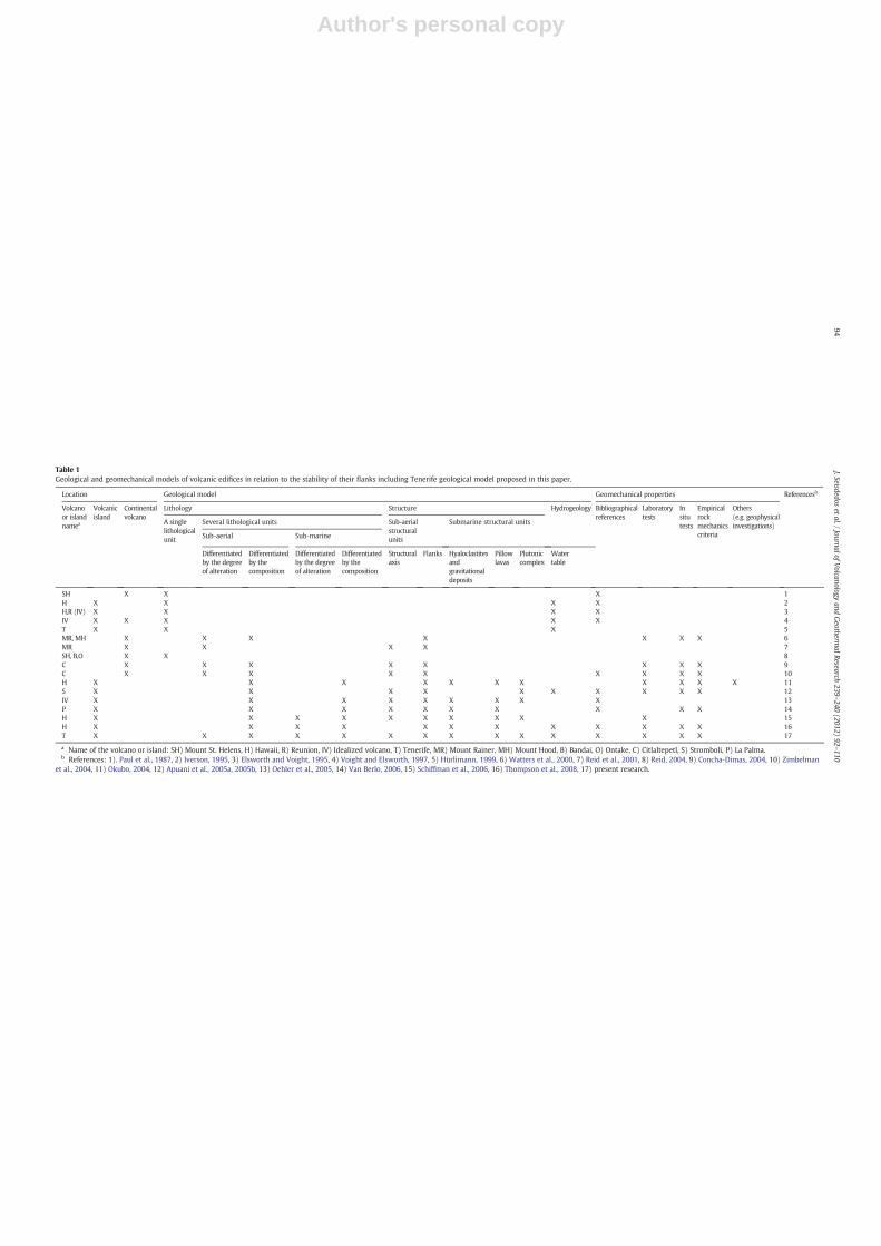

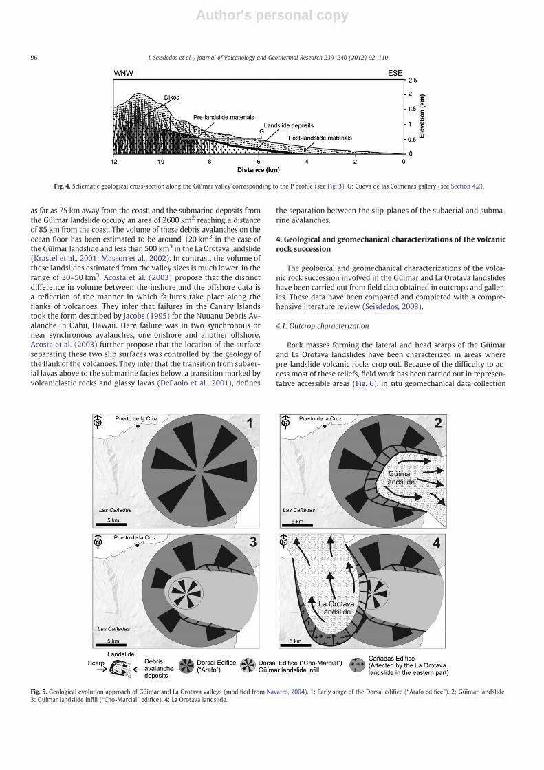


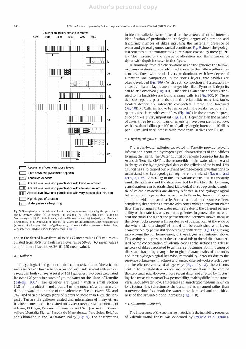

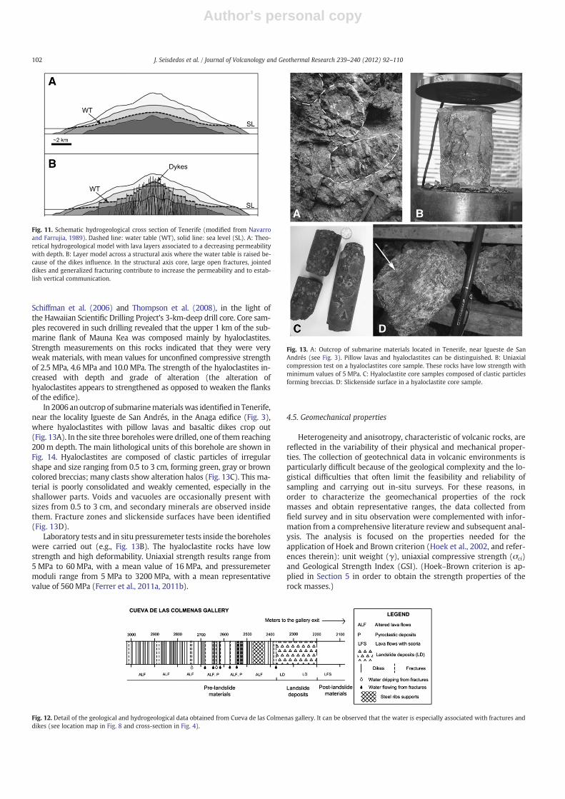


![[XLS] · Web viewV33S-CE V42R-CE V42RE-CE V50-CE V50R-CE V50SR-CE V60R-CE V60RE-CE V84R-CE W-121 W-121-24V W-138PK SAA 3400 540 SAE AS160 AS165 17803 18003 18149 18207 18258 18262](https://static.documents.pub/doc/80x56/5afca39c7f8b9aa34d8c5e86/xls-viewv33s-ce-v42r-ce-v42re-ce-v50-ce-v50r-ce-v50sr-ce-v60r-ce-v60re-ce-v84r-ce.jpg)

