12
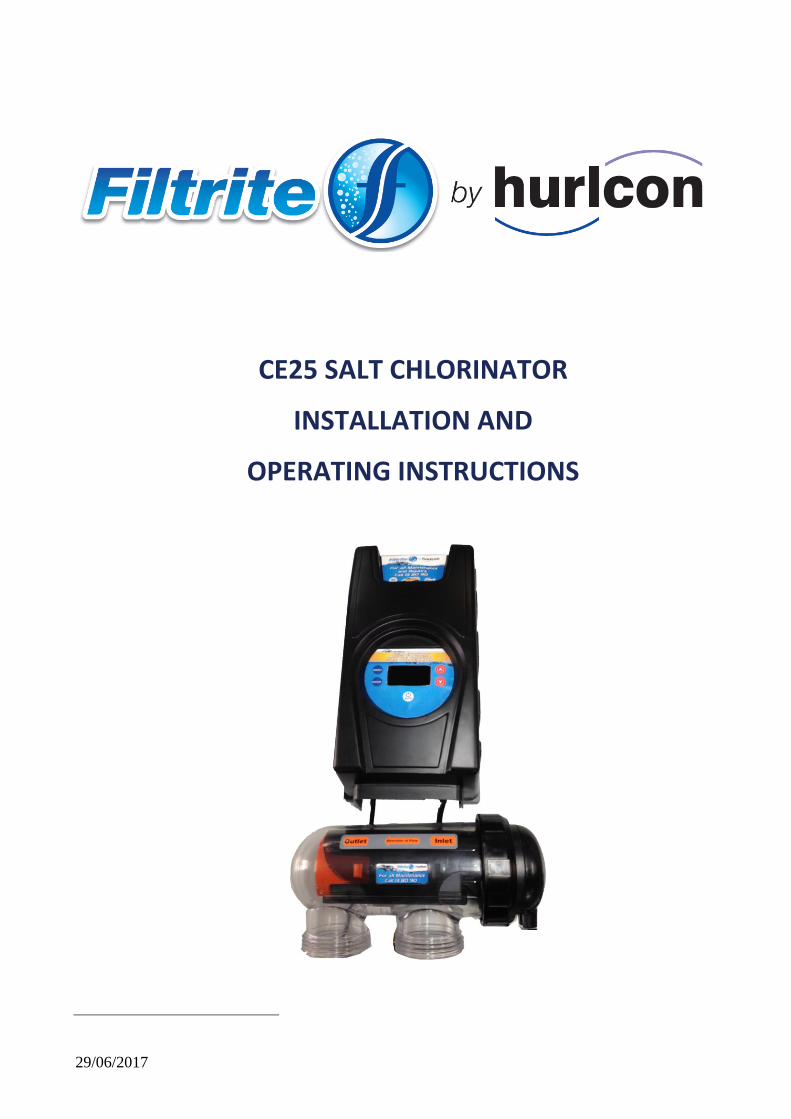
29/06/2017 CE25 SALT CHLORINATOR INSTALLATION AND OPERATING INSTRUCTIONS
29/06/2017
CE25 SALT CHLORINATOR
INSTALLATION AND
OPERATING INSTRUCTIONS
Inst.335 CE25 Chlorinator V07.17 2
INDEX
General Overview ...................................................................................................... 3
Control Box Installation .............................................................................................. 3
Cell Installation ......................................................................................................... 4
Pool Preparation ....................................................................................................... 5
Programming ........................................................................................................... 5
Chlorine Output ........................................................................................................ 6
User Mode .............................................................................................................. 6
Chlorine output level .................................................................................................. 7
General Operation/Pool Chemistry ............................................................................... 7
Setting the right Chlorine Output and Filtration Time. ..................................................... 7
Chlorinator Maintenance and Troubleshooting ............................................................... 8
Troubleshooting ...................................................................................................... 10
Warranty….. ........................................................................................................... 11

Inst.335 CE25 Chlorinator V07.17 3
GENERAL OVERVIEW
Congratulations! You have purchased an Filtrite by Hurlcon CE25 Salt Chlorinator. Please read the instructions carefully and your purchase will provide you with years of trouble free use. Your Filtrite by Hurlcon chlorinator works by converting some of the salt (sodium chloride) in your pool into chlorine which starts to destroy algae and bacteria and sanitises your pool. As part of the process, the chlorine is converted back into salt and hence salt is not consumed. Your chlorinator control has many features which ensure simple operation of your chlorinator and filtration system. The CE25 chlorinator has an internal electronic time clock designed to operate the filtration pump up to 2 separate time periods each day. The control has a non replaceable backup power source which is designed to maintain timer setting memory in the event of an infrequent and short power interruption. WARNING: This appliance is not intended for use by persons including young children or infirm persons with reduced physical, sensory or mental capabilities, or lack of experience or knowledge, unless they have been given supervision or instruction concerning use of the appliance by a person responsible for their safety. Please ensure that young children are supervised to ensure that they do not play with the pump or chlorinator. To avoid a safety hazard, the supply cord if damaged, must only be replaced by a suitably qualified person.
CHLORINATOR CONTROL INSTALLATION
The CE25 Chlorinator control has a Rating of IPX3 enabling it to be installed outdoors. Regulations require that the control is not allowed to be located within 3.5 metres of the pool water. The control should be installed in a well ventilated position ideally away from direct sunlight. Ensure that the unit is not located near pool chemicals as fumes may damage the control. When installing the control on a post, first attach a flat waterproof panel at least 300mm wide by 500mm long. Make sure the control is located centrally on the panel and sits flat. Plug the 3 pin plug into a suitable weatherproof outlet and then plug the pump into the 3 pin socket in the Chlorinator control. Note: The pump current rating must not exceed 8 amps.

Inst.335 CE25 Chlorinator V07.17 4
CELL INSTALLATION
The chlorinator cell must be located last in the pipe work just prior to the return to the pool. If valves are installed between the Chlorinator and the pool outlet, it is essential that they cannot deadhead the pump. If the pressure in the cell exceeds 250kPa and/or the water temperature exceeds 40 degrees C, the cell may fail.
WARNING: Never install the cell before the pump or heater
The cell MUST be installed with the barrel unions underneath (water connections pointing downwards) and the cell should be horizontal. Both 40mm and 50mm fittings have been provided. Use 40mm (1.5”) high pressure PVC pipe and glue into the 40MM barrel union tails or use 50mm (2”) high pressure PVC pipe and glue into the 50mm barrel union tails. Make sure that the o’rings are correctly fitted and the unions are tightened firmly. Direction of flow through the cell is critical – unit must be plumbed with the water entering the cell at the end closest to the terminal connections (as indicated by flow direction label mounted on cell)
WARNING: It is essential that pipe work and equipment do not allow gases generated from the cell to
collect and build up.
WARNING: Cell must be installed vertically with water connections pointing downwards – this
creates a safety gas trap. Installation in any other way may cause explosion, injury or
death.
WARNING: Cell must be installed in the return pipework to the pool. Always install after filter, gas
heater, solar heater or heat pump connections.
WARNING: DO NOT install isolation valves on inlet or outlet of cell.

Inst.335 CE25 Chlorinator V07.17 5
Once the cell is located, connect the black multi-core cable to the cell. The blue wire must be connected to the blue terminal. The cable is designed to come from below the cell. Make sure wing nuts are correctly tightened to ensure good contact.
POOL PREPARATION
The recommended salt level for the CE25 salt chlorinator is 6,000ppm. The chlorinator requires between 5,000ppm and 6,000 ppm of salt dissolved into the pool water. The level of salt will depend on water temperature, but if a level of 6,000 ppm dissolved salt is allowed for, your chlorinator will always be able to produce the maximum level of chlorine. We recommend you add 6 kg’s of salt for every 1,000 litres of water (a typical pool of around 50,000 litres requires 300kg of salt). Salt should always be added at the shallow end of the pool and allowed to dissolve. Running the pump will mix the water and speed the dissolving process. You should also use your pool brush to move the salt around – DO NOT ALLOW SALT TO SIT ON THE BOTTOM OF THE POOL. WARNING: Never add salt to the skimmer box!! NOTE: Plug the pump directly into a power outlet (bypass the Chlorinator) and run for 8-10 hours to ensure the salt is dissolved prior to running the chlorinator. When the salt is dissolved, connect the pump to the chlorinator and run it on maximum chlorine output. Check that low salt is not indicated on the screen. If it is, check again in 24 hours. If the low salt indicator still persists, have the salt level checked by your local pool shops and ensure it is increased to 6,000 ppm.
PROGRAMMING
Setting Current Time/Day Select Off
(a) Press the MENU button and screen should display CLK. Press ENTER (b) Press ENTER and the hour digit will flash. Use up and down arrows to adjust. (c) Press ENTER to change to minutes and set. (d) Press ENTER and select AM or PM (e) Press MENU to save
Setting Timers Your Chlorinator has 2 timers enabling you to set different periods in which your chlorinator/pump will operate. Timers are set by entering a start time and an off To set timers, do the following:
(a) Press the MENU button twice and screen should display TMR. Press ENTER (b) Use up and down arrows to adjust start time for TIMER1. Press ENTER (c) Use up and down arrows to adjust the off time for TIMER 1. Press ENTER. (d) Repeat for TIMER 2
Programming Recommendations It isl recommend that you use two timers, one for the morning and one for the evening and typically for periods of 2-5 hours for each. Your chlorinator is most effective if running in the early morning or evening when it is cooler (strong sunlight consumes more chlorine). As a factory default, the control is set to come on at 08:00am and 04:00pm both for periods of 4 hours.

Inst.335 CE25 Chlorinator V07.17 6
CHLORINE OUTPUT
To adjust the chlorine output:
(a) Use Increase/Decrease arrows for setting the chlorine output level of the chlorinator. The chlorinator output can be set from levels 1 through to 8.
(b) Chlorine Output display shows the level set
USER OPERATION
The user mode buttons enable you to select Pool or Spa mode and to manually control the Chlorinator/Pump. Functions are as follows:
(a) POOL MODE:
Auto - Running The Chlorinator/Pump will run according to how you have set the timers
Manual -Running The Chlorinator/Pump will run continuously.
Manual - Stopped The Chlorinator/Pump will stay off continuously.
Maximum efficiency will be achieved from you chlorinator at the following levels: Water temperature 25 Degrees – Salt level required is 6,000 ppm
FAULT CODES
The user display can indicate the following fault codes;
NO F – No flow indication
LO S – Low salt indication
Refer to troubleshooting table at the end of this manual for actions to correct these errors.

Inst.335 CE25 Chlorinator V07.17 7
SETTING THE RIGHT CHLORINE OUTPUT AND FILTRATION TIME
Your CE25 Chlorinator must be run every day to ensure that your pool is correctly sanitised. As the sun dissipates chlorine, running times are higher in the summer compared to the winter. It is recommend that you initially run you chlorinator at maximum output
Summer You should set your Chlorinator to operate for 8 to 10 hours per day. Ideally, run it for 4-5 hours in the morning (say 8-12pm) and 4-5 hours in the evening (say 6.00-11pm). In extremely hot weather it may be necessary to extend the running time if you find that the free chlorine level is too low. To prevent consumption of chlorine by sunlight, try adding Cyanuric Acid as recommended by your local pool professional. Additional benefit will be gained by operating your chlorinator and pump into the evening when the strong sunlight has abated. Chlorine is most effective when the pH of your pool water is 7.4. The electro-chemical process of the chlorinator, (change salt into chlorine) will automatically raise the pH of your pool water, so it is very important to check your pH weekly and adjust as necessary.
Winter You should set your Chlorinator to operate for 6 to 8 hours per day. Again, running it in the morning and evening is preferable.
Checking Chlorine Level Ideally, check you Chlorine level after the morning operating period. The free chlorine residual level should be somewhere between 1 and 3 part per million. Increase or decrease the output of the Chlorinator to get the right residual chlorine level. It may also be necessary to adjust the operating period if you are running at minimum or maximum output.
STABILISER
As previously mentioned, sunlight rapidly dissipates the amount of free chlorine in your pool. Chlorine stabiliser greatly reduces this effect.Without stabiliser, you may need to run your Chlorinator and filtration system up to 16 hours per day longer!!!
Keep the Stabiliser reading between 30 and 60ppm.
pH Level You should keep you pH level between 7.2 and 7.4 for fibreglass pools and 7.2 to 7.6 for other pools.
Total Alkalinity The ideal range is between 80 and 120 ppm.
Salt Level Although salt is not consumed by the Chlorinator, salt is lost during backwashing, and when your pool overflows due to rain or splashing. The correct salt level is important to cell life and the effective operation of your chlorinator. Salt level should be maintained around 6,000ppm but should never be allowed to fall below 4,000ppm.

Inst.335 CE25 Chlorinator V07.17 8
A typical pool of around 50,000 litres requires 300kg of salt to initially set-up the pool to 6,000ppm.
A low salt level warning is indicated on your CE25 Chlorinator if the salt level drops. If Low Salt is indicated, check again in 24 hours and then if it is still indicated, add two 25kg bags of salt to the shallow end of your pool. Run the filtration system for approx. 6 hours to help mix the salt in the pool. It can take up to a day for the salt to fully dissolve. If the low salt light is still on, then you should get your pool water tested. If the Salinity is above 6,000ppm then you may need to have your Chlorinator checked. Warning: Never add salt directly to the skimmer box. This practice should be avoided as it allows very high concentrations of salt to be passed through your filtration and other pool equipment.
CHLORINATOR MAINTENANCE AND TROUBLESHOOTING
If the supply cord is damaged, it must be replaced by a service agent or a similarly qualified person in order to avoid a hazard. Warning: Operating the Chlorinator with less than 4,000 ppm of dissolved salt in the water may cause damage to the cell and will void the warranty. Never start chlorinator until the correct quantity of salt has been added and dissolved in your pool water.
Cell Maintenance
Your CE25 Chlorinator has an automatic cleaning feature that under normal conditions, will keep the cell plates clear of deposits of salt and calcium. CE25 Series cells have a negative charge sensor that monitors the flow and salt levels of the water. This sensor is designed to be fail safe. As it is negative charges deposits of calcium or other debris may be deposited on it and cause it to indicate a low salt or no flow condition. Should a low salt condition be indicated, have your salt level checked at your local pool shop. If the low salt condition persists, or a no flow condition is indicated when the supply pump is operating, you may need to manually clean your chlorinator cell.
Cell Cleaning Instructions:
- close applicable valves
- disconnect the Chlorinator from the mains by removing the 3 pin plug
- disconnect the cell wires - undo the barrel nuts connecting the cell to your filtration system. - turn the cell upside down (inlet and outlet on top) and fill the cell with an approved cell cleaning solution
available through Clark Rubber Pool Shops – DO NOT USE HYDROCHLORIC ACID AS THIS CAN DAMAGE THE CELL AND VOID WARRANTY
- repeat if necessary and then rinse well in clean water - re-install the cell ensuring o-rings are correctly located and barrel nuts are tightened to prevent leaks - re-connect cell wires with wing nuts supplied making sure the blue wire is connected to the blue terminal.
Incorrect connection may damage your chlorinator control. Tighten wing-nuts to ensure the electrical connection is sound.
- Return all valves to their normal positions, re connect power to the Chlorinator and turn on at power point. WARNING: Follow safety instructions provided with the Hydrochloric acid or cleaning solution. When handling Hydrochloric Acid, the use of eye protection, mask and gloves are highly recommended. Extreme caution should be taken whenever handling Hydrochloric Acid or Cell Cleaning Solution.

Inst.335 CE25 Chlorinator V07.17 9
Maintenance of your Chlorinator Maintenance Schedule: You new product incorporates moving parts and withstands high velocity water with chemicals in it. Some of these parts will wear in the normal course of use and require regular checks and maintenance. Performing these checks and maintenance will identify parts that have worn and require repair/replacement before further serious damage is sustained. A small amount of regular care and attention to your pool equipment will help ensure long life and trouble free performance. Timing Maintenance Check Service action (if required) Fortnightly Check cell for calcium build up
Check water chemistry Check cable connections to cell
Soak electrode in a cell cleaning soloution. Use a soft brush only if required Balance pH in pool and adjust output of unit to ensure satisfactory production of chlorine. Ensure no water contact is occurring with pins
Three Monthly Check cell connections for leaks Isolate Pump, turn power off, clean and grease O rings or replace if necessary
Six Monthly Check chlorine levels and pump operating hours Prevent insect ingress to controller
Adjust timer and output depending on demand for current season. Turn controller off, use a insect spray and spray onto walls around controller. Do not spay directly into unit.
Important note: Regular maintenance is important to ensure long life and trouble free performance of your pool equipment. If unable to perform the maintenance yourself, contact your local AstralPool office who will arrange a trained service technician to perform the maintenance for you.
Record your Equipment details here for quick reference: Model No.: ____________________________ Serial No.: ____________________________
Inst.335 CE25 Chlorinator V07.17 10
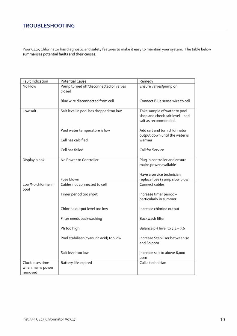
TROUBLESHOOTING
Your CE25 Chlorinator has diagnostic and safety features to make it easy to maintain your system. The table below summarises potential faults and their causes.
Fault Indication Potential Cause Remedy
No Flow Pump turned off/disconnected or valves closed Blue wire disconnected from cell
Ensure valves/pump on Connect Blue sense wire to cell
Low salt Salt level in pool has dropped too low Pool water temperature is low Cell has calcified Cell has failed
Take sample of water to pool shop and check salt level – add salt as recommended. Add salt and turn chlorinator output down until the water is warmer Call for Service
Display blank No Power to Controller Fuse blown
Plug in controller and ensure mains power available Have a service technician replace fuse (3 amp slow blow)
Low/No chlorine in pool
Cables not connected to cell Timer period too short Chlorine output level too low Filter needs backwashing Ph too high Pool stabiliser (cyanuric acid) too low Salt level too low
Connect cables Increase timer period – particularly in summer Increase chlorine output Backwash filter Balance pH level to 7.4 – 7.6 Increase Stabiliser between 30 and 60 ppm Increase salt to above 6,000 ppm
Clock loses time when mains power removed
Battery life expired Call a technician

Inst.335 CE25 Chlorinator V07.17 11
WARRANTY
AstralPool Australia Pty Ltd (ABN 97 007 284 504) ("AstralPool") provides the following warranty in relation to the Filtrite by Hurlcon CE25 Series Salt Chlorinator ("Product"). The benefits of this warranty are in addition to any rights and remedies imposed by Australian State and Federal legislation that cannot be excluded. Nothing in this warranty is to be interpreted as excluding, restricting or modifying any State or Federal legislation applicable to the supply of goods and services which cannot be excluded, restricted or modified. WARRANTY AstralPool warrants that, subject to the exclusions and limitations below, the Product will be free from defects in materials and workmanship during the warranty period. The warranty periods are set out below and commence 30 days after the date of purchase (to allow for installation). The warranty period may vary for different parts of the Product.
Parts Warranty Period
Electrical Control 24 Months
Electrode 24 Months
If a defect appears in the Product before the end of the warranty period and AstralPool finds the Product to be defective in materials or workmanship, AstralPool will, in its sole discretion, either: (a) replace or repair the Product or the defective part of the Product free of charge; or (b) Cause the Product or the defective part of the Product to be replaced or repaired by an Authorised AstralPool Service Agent free of charge. AstralPool reserves the right to replace defective parts of the Product with parts and components of similar quality, grade and composition where an identical part or component is not available. Goods presented for repair may be replaced by refurbished goods of the same type rather than being repaired. Refurbished parts may be used to repair the goods. WARRANTY CLAIMS 1. If a fault covered by warranty occurs, the customer must first contact AstralPool at the contact address listed below, or an Authorised AstralPool Service Agent. 2. Any warranty claim must be accompanied by: (a) proof of purchase; (b) full details of the alleged defect; and (c) appropriate documentation (such as historical and maintenance records). 3. The customer must make the Product available to AstralPool or its Authorised AstralPool Service Agent for inspection and testing. AstralPool or its Authorised AstralPool Service Agent will attend the premises where the Product is installed for inspection and testing. If the Product is installed: (a) outside a capital city metropolitan area; and (b) is not within a 20 km radius of an Authorised AstralPool Service Agent; then the customer may have to pay a travel fee. 4. If such inspection and testing finds no defect in the Product, the customer must pay AstralPool's usual costs of service work and testing. If such inspection and testing finds a defect that is not covered by this warranty, the customer must pay AstralPool's usual costs of service work plus any parts and labour required to repair the Product, unless recoverable from AstralPool on the failure of any statutory guarantee under the ACL.

Inst.335 CE25 Chlorinator V07.17 12
Exclusions The warranty will not apply where: (a) the customer is in breach of the Terms and Conditions of Sale; (b) the Product was used for a purpose other than one it was intended for; (c) the Product was repaired, modified or altered by any person other than AstralPool; (d) the Product has not been installed, maintained and/or operated in complete compliance with the installation and
operating instructions and any instructions by AstralPool; (e) the Product has been subject to accident, negligence, alteration, abuse or misuse. The warranty does not extend to: a) normal wear and tear; b) weather and other environmental conditions including but not limited to storm, flood, and/or heat wave damage;
or c) service and maintenance items. Examples of exclusions include but are not limited to:
Use of sharp tools for cleaning electrodes
Incorrect installation Commercial Installations On commercial installations, such as health clubs, motels/hotels and hydrotherapy facilities, the warranty is limited to parts and in field labour (within capital city metropolitan areas or 20 km radius of Authorised AstralPool Service Agents) for a period of 12 months from the date of purchase plus 30 days to allow for installation. LIMITATIONS AstralPool makes no express warranties or representations other than set out in this warranty. The repair or replacement of the Product or part of the Product is the absolute limit of AstralPool's liability under this express warranty. Our goods come with guarantees that cannot be excluded under the Australian Consumer Law. You are entitled to a replacement or refund for a major failure and for compensation for any other reasonably foreseeable loss or damage. You are also entitled to have the goods repaired or replaced if the goods fail to be of acceptable quality and the failure does not amount to a major failure
Clark Rubber Franchising Pty Ltd. ACN. 065 708 723
www.clarkrubber.com.au email:
Information and specifications subject to change without notice.


