SCAD ENGINEERING COLLEGE II – YEAR NOTES DEPARTMENT OF CIVIL ENGINEERING CE6401 CONSTRUCTION MATERIALS L T P C 3 0 0 3 OBJECTIVES: To introduce students to various materials commonly used in civil engineering construction and their properties. UNIT I STONES – BRICKS – CONCRETE BLOCKS 9 Stone as building material – Criteria for selection – Tests on stones – Deterioration and Preservation of stone work – Bricks – Classification – Manufacturing of clay bricks – Tests on bricks – Compressive Strength – Water Absorption – Efflorescence – Bricks for special use – Refractory bricks – Cement, Concrete blocks – Light weight concrete blocks. UNIT II LIME – CEMENT – AGGREGATES – MORTAR 9 Lime – Preparation of lime mortar – Cement – Ingredients – Manufacturing process – Types and Grades – Properties of cement and Cement mortar – Hydration – Compressive strength – Tensile strength – Fineness– Soundness and consistency – Setting time – Industrial byproducts – Fly ash – Aggregates – Natural stone aggregates – Crushing strength – Impact strength – Flakiness Index – Elongation Index – Abrasion Resistance – Grading – Sand Bulking. UNIT III CONCRETE 9 Concrete – Ingredients – Manufacturing Process – Batching plants – RMC – Properties of fresh concrete – Slump – Flow and compaction Factor – Properties of hardened concrete – Compressive, Tensile and shear strength – Modulus of rupture – Tests – Mix specification – Mix proportioning – BIS method – High Strength Concrete and HPC – Self compacting Concrete – Other types of Concrete – Durability of Concrete. UNIT IV TIMBER AND OTHER MATERIALS 9 Timber – Market forms – Industrial timber– Plywood – Veneer – Thermacole – Panels of laminates – Steel – Aluminum and Other Metallic Materials – Composition – Aluminium composite panel – Uses – Market forms – Mechanical treatment – Paints – Varnishes – Distempers – Bitumens. UNIT V MODERN MATERIALS 9 Glass – Ceramics – Sealants for joints – Fibre glass reinforced plastic – Clay products – Refractories – Composite materials – Types – Applications of laminar composites – Fibre textiles – Geomembranes and Geotextiles for earth reinforcement. TOTAL: 45 PERIODS 1
Transcript
SCAD ENGINEERING COLLEGE II – YEAR NOTES DEPARTMENT OF CIVIL ENGINEERING
CE6401 CONSTRUCTION MATERIALS L T P C 3 0 0 3 OBJECTIVES:
To introduce students to various materials commonly used in civil engineering construction and their properties.
UNIT I STONES – BRICKS – CONCRETE BLOCKS 9
Stone as building material – Criteria for selection – Tests on stones – Deterioration and
Preservation of stone work – Bricks – Classification – Manufacturing of clay bricks – Tests
on bricks – Compressive Strength – Water Absorption – Efflorescence – Bricks for special
textiles – Geomembranes and Geotextiles for earth reinforcement. TOTAL: 45 PERIODS
1
SCAD ENGINEERING COLLEGE II – YEAR NOTES DEPARTMENT OF CIVIL ENGINEERING
PART - A
UNIT I STONES – BRICKS – CONCRETE BLOCKS
1. What are the uses of stone in construction? Masonry
Pavements
Flooring
Facing work in buildings
Concrete aggregates
2. List the characteristics to be considered in selection of stones. Crushing strength
Appearance
Density
Durability
Easiness of dressing
Fire resistance
Fracture
Impact resistance
Hardness
Resistance to wear
3. List some causes for deterioration of stones. Alternate wetting and drying.
Alternate freezing and thawing.
Deleterious substances present in the atmosphere near the seashores and industrial areas.
Movement of chemicals between materials.
Nature of mortar..
Wind.
4. List some methods of conservation of granite. Consolidation using consolidates
Injection using injection materials and
Filling using filling materials.
5. What are the field tests to be conducted on stones? Absorption test
Smith's test
Toughness test
Moh's scale of hardness test
Acid test
Crystallization test
6. Name the laboratory tests to be conducted on stones. Attrition test
Crushing test
Freezing and thawing test
Hardness test
2
SCAD ENGINEERING COLLEGE II – YEAR NOTES DEPARTMENT OF CIVIL ENGINEERING
Impact test
Microscopic test
7. Classify minerals based on abrasion. Talc
Gypsum
Calcite
Fluorspar
Apatite
Orthoclase feldspar
Quartz
Topaz
Corundum (Saphire)
Diamond
8. Write notes on Acid test on stone.
This is to test the presence of poorly weathering calcium carbonates in sandstones.
The test consists of placing a cube of the stone weighing about 50 to 100 gm in one per cent
hydrochloric acid for 7 days. A good building stone should be free from powder formation on
the surface of the cube and the sharp edges should not be broken up after the above
immersion. 9. Write notes on Crystallization test.
This test consists of immersing a sample of stone (cubes of say 40 mm) in 14 %
sodium sulphate solution for two hours and then drying it in an oven at 100°C. This
procedure is repeated for at least five times. The loss of weight and the presence of cracking
are noted. There should not be any visible defect formed, and the loss in weight should be
minimal. 10. Classify bricks according to their use.
Common bricks
Engineering bricks (special bricks for carrying heavy loads)
Facing bricks
Fire bricks
Specials (special shapes)
11. List the tests made on bricks. Compressive strength
Water absorption
Efflorescence
Dimensional tolerance
Hardness
Soundness.
Structure
3
SCAD ENGINEERING COLLEGE II – YEAR NOTES DEPARTMENT OF CIVIL ENGINEERING
UNIT - II
LIME – CEMENT – AGGREGATES – MORTAR
1. What is curing? State its importance.
It is absolutely essential that moisture should be present in the initial stages for the
development of strength of cement. This process of supplying moisture environment is
known as curing. Thus, curing of the products of cement is very important in all the works
connected with cement like construction of masonry. Plastering, concreting. etc. 2. What is White cement and where is it used?
White cement is made from chalk or limestone or shelllime free from impurities and
white clays like china clay free from oxides of iron, manganese, etc. White cement is very
much used for making of mosaic tiles, coloured cements, etc. 3. What are the types of cement produced in India?
Ordinary portland cement (OPC)
Portland pozzolana cement (PPC)
4. What are the IS specifications of Cement? Ordinary portland cement (OPC) in 3 grades
Grade 33 IS 269-1989 designated as C-33
Grade 43 — IS 8112-1989 designated as C-43
Grade 53 — IS 12269-1987 designated as C-53
Portland pozzolana cement (PPC) (a mixture of OPC and Pozzolanas)
IS 1489 (Pan 0-1991 (flyash-based)
IS 1489 (Part II) -1991 (calcined clay -based)
Sulphate -resisting cement—IS 12330-1988
Portland slag cement—IS 455-1989 (PSC)
Low -heat cement—IS 12600-1989
Rapid -hardening cement—IS 8041-1990
5. List the physical tests on Cement. Fineness test
Consistency test
Soundness test
Setting time test
6. What is hydration of cement?
Hydration of cement is a chemical reaction that happens when cement is introduced to
water and it produces heat. In very massive construction, this effect can raise the temperature
of concrete as much as 50°C. In such cases, we should use low—heat cements or adopt
cooling methods. 7. List the tests conducted on aggregates.
Particle Size,(grading) shape and flakiness (3tests)
Organic impurities
Moisture content
percent fines value
Water absorption and specific gravity
Aggregate crushing value
Aggregate impact value
4
SCAD ENGINEERING COLLEGE II – YEAR NOTES DEPARTMENT OF CIVIL ENGINEERING
Aggregate abrasion value
Bulk density and void ratio
8. Classify aggregates based on their shape. Rounded
Irregular or partly -rounded
Angular
Flaky
9. Define flakiness index.
The flakiness or elongation index of an a aggregate is defined as the percentage
weight of particles in the given aggregate which has its length greater than 1.8 times and its
least dimension (thickness) is less than 3/5 (or 0.6) times its mean dimension. 10. What is Impact test?
This test is for aggregates in concrete that undergoes impact as in runways in airports.
Materials passing through 12.5 mm and retained as 10 mm are tilled in the standard cylinder
in three layers, each layer tamped with 25 strokes of an iron rod. A hammer weighing 14 kg
is dropped from a height of 380 mm 15 times and the resulting material is sieved through a
2.36 mm I.S. sieve. The percentage fine is the aggregate impact test value. 11. Write notes on Abrasion test.
This test is for the stones used in road construction. We use the Deval's abrasion
testing machine or the Los Angeles abrasion machine for this purpose. It should not be more
than 16 per cent for a good aggregate. 12. Write the procedure of Los Angles Abrasion test.
A sample of specified grading which varies with the maximum size of aggregate to be
tested is placed in the machine with steel or cast iron spheres of 48 mm diameter and 390 to
445 gm weight. The machine is rotated for specified revolutions depending on the grading
(500 to 1000 revolutions). The resulting material is sieved through 1.7 mm sieve. The
percentage of wear is called the Los Angeles aggregate abrasion value. 13. Why gypsum is used in cement?
Gypsum is used for retarding the setting time of cement. 14. What are the two methods of manufacture of cement?
Wet process
Dry process
5
SCAD ENGINEERING COLLEGE II – YEAR NOTES DEPARTMENT OF CIVIL ENGINEERING
UNIT III
CONCRETE 1. List the various operations requires in the production of concrete.
2. What are the stages of concrete? Fresh concrete
Hardened concrete
3. What is Fresh concrete?
The fresh concrete or plastic concrete is the initial stage of concrete period and it is
counted from the mixing stage till it is transported, placed, compacted and finished in the
position. 4. Define workability.
It is defined as the property of freshly mixed concrete or mortar which determines the
case and homogeneity with which it can be mixed, placed, compacted and finished. The
degree of ease in working with concrete is called workability. 5. List some tests to measure workability.
Slump test
Compacting Factor test
Flow test
Vee-Bee test
Kelly Ball test
6. What are the limitations of slump test? It is not suitable for concrete made with aggregate size more than 40 mm
Not suitable for harsh mixes
7. Write the formula for flow percent.
The average diameter of the spread concrete is measured and flow of concrete is obtained in percentage.
Flow percent = −25
x 100
25
6
SCAD ENGINEERING COLLEGE II – YEAR NOTES DEPARTMENT OF CIVIL ENGINEERING
The value may be between 0 to 150.
8. List the factors affecting workability Water content
Mix proportion
Size of aggregate
Shape of aggregate
Surface texture of aggregate
Grading of aggregate
Use of admixtures
9. What is a good concrete?
A good concrete is one in which the ingredients are properly distributed to make a homogenous mixture and it should not show any sign of segregation or bleeding. 10. Define segregation.
Segregation can be defined as the separation of coarse aggregate from the main mass
of concrete in the plastic stage and it occurs in case of dry mix of insufficient and non -
uniform mixing. 11. Define bleeding.
Bleeding is a form of segregation in which some of water in the mix tends to rise the
surface of freshly placed concrete. This is because of the inability of the solid constituents of
the mix to hold all the mixing water in the place when they settle downwards. 12. List the factors affecting compressive strength of concrete.
The characteristics of cement.
The characteristics and properties of aggregates.
The degree of compaction
The efficiency of curing
Age at the time of testing.
Conditions of testing.
13. What is Water-Cement ratio?
The water -cement ratio, defined as the ratio of the mass of free water (i.e. excluding
that absorbed by the aggregate) to that of cement in a mix, is the most important factor that
controls the strength and many other properties of concrete. In practice, this ratio lies
generally in the range of 0.35 to 0.65, although the purely chemical requirement (for the
purpose of complete hydration of cement) is only about 0.25.
UNIT IV TIMBER AND OTHER MATERIALS
1. Define Plywood. Plywood is a laminate made of thin layers of wood.
2. Write about Veneer.
In woodworking, veneer refers to thin slices of wood, usually thinner than 3 mm, that
typically are glued onto core panels (typically, wood, particle board or medium-density
fiberboard) to produce flat panels such as doors, tops and panels for cabinets, parquet floors
and parts of furniture.
7
SCAD ENGINEERING COLLEGE II – YEAR NOTES DEPARTMENT OF CIVIL ENGINEERING
3. What are the types of Veneer?
Raw veneer
Paper backed veneer
Phenolic backed veneer
Laid up veneer
Reconstituted veneer
Wood on Wood or 2-ply veneer
4. What are the Advantages of using veneer?
Furniture made with wood veneer uses less wood than the same piece of furniture
made with solid wood. Some projects built using wood veneer would not be possible to
construct using solid lumber, owing to expansion and contraction caused by fluctuation of
temperature and humidity. 5. List the applications of Thermocole.
Its high thermal insulation makes it an excellent material to use in the construction
of walls and ceilings and its high sound absorption makes it the ideal choice for sound-proofing.
Another recent application of Thermocol (EPS) is as ―Geofoam‖ in landfills. This application is made possible because of Thermocol’s (EPS’s) light weight, water resistance, dimensional stability and inert nature.
6. List the application of Aluminium composites.
A popular application for aluminium composite is folded structures. From sign trays
to fascia panels and column cladding aluminium composite is easy to form and light enough
to install easily. Using the correct type of tooling aluminium composite can be scored and
then folded. 7. Write notes on Paint.
Paint is any liquid, liquefiable, or mastic composition that, after application to a
substrate in a thin layer, converts to a solid film. It is most commonly used to protect, color,
or provide texture to objects. 8. What is a binder?
The binder is the film-forming component of paint. It is the only component that must
be present. The binder imparts adhesion and strongly influences properties such as gloss,
durability, flexibility, and toughness. 9. What is the purpose of a diluent?
The main purposes of the diluents are to dissolve the polymer and adjust the viscosity
of the paint. It is volatile and does not become part of the paint film. It also controls flow and
application properties, and in some cases can affect the stability of the paint while in liquid
state. Its main function is as the carrier for the non volatile components. 10. What are pigments? How are they classified?
Pigments are granular solids incorporated in the paint to contribute color.
Pigments can be classified as either natural or synthetic. Natural pigments include various
clays, calcium carbonate, mica, silicas, and talcs. Synthetics would include engineered
A laminar composite is a composite material that consists of two or more layers of
different materials that are bonded together. They are also called laminated composites or
laminates. A laminate usually consists of two or more layers of planar composites in which
each layer (also called lamina or ply) may be of the same or different materials. 9. Define Refractories.
Refractories are defined as non-metallic materials having those chemical and physical
properties that make them applicable for structures, or as components of systems, that are
exposed to environments above 1,000 °F. A refractory material is one that retains its strength
at high temperatures. 10. What is a sealant?
Sealants are typically lower strength, yet flexible, bonding agents used between
substrates of differing physical properties to form a seal between the materials. A sealant may
be viscous material that has little or no flow characteristics and which stay where they are
applied. 11. What is a ceramic?
A ceramic is an inorganic, nonmetallic solid prepared by the action of heat and
subsequent cooling. Ceramic materials may have a crystalline or partly crystalline structure,
or may be amorphous (e.g., a glass).
PART - B UNIT I
STONES – BRICKS – CONCRETE BLOCKS
1. Write the Criteria for Selection of Stones Criteria for selection of stones:
Stone should be selected according to their use. In any case, it should be durable and free from defects.
1. Stone for masonry. Any type of stone can be used for rough work like random rubble.
However, for ornamental works and dressing the stones to different finishes (as for ashlar
work ) we have to use stones suitable for these purposes. Soft stones like limestones and
sandstones can be dressed more easily than granite. For ornamental works in temples or
heavy engineering works like facing work in docks and harbours or bridge piers, we will
prefer well- dressed granite.
2. Stone for pavements. Generally, hardstones of any type can be used for paving walkways, driveways, etc.
3. Stone for flooring. Stones are used for heavy duty flooring in many situations. Nowadays, with the help of machines, we can produce large slabs for flooring even from hard rocks like
10
SCAD ENGINEERING COLLEGE II – YEAR NOTES DEPARTMENT OF CIVIL ENGINEERING
granite. In some locations like bathrooms, marble floorings are preferred. Materials like
marble, kotastones can take polish and are prefered in many places. They can also be
obtained in pleasing colours. Cuddapa slabs are popular for using in kitchen platforms,
shelves, etc.
4. Stones for facing work in buildings. The facing stones should have attractive colours. It
should be durable. Both impervious stones like granites, marbles and pervious stones like
limestones are used. The impervious varieties are preferred as they do not get change in
colour with time, especially in an industrial atmosphere.
5. Stones for concrete aggregates. Hard igneous rocks like granite are always preferred for
high strength concrete as needed in prestressed concrete. Aggregates of moderate strength
like limestones are also useful for making concrete of moderate strength.
2. Enumerate the characteristics to be considered in selection of stones. Characteristics to be considered in selection of stones:
The desirable qualities depend on the use of the stone. Hard stones are used for heavy
engineering works like building quay walls. Many types of stones are used as aggregates for
concrete. Stones like marbles are used for appearance. Now, we will deal with the important
general properties to took for.
1. Crushing strength. The following are the ultimate strengths of some of the common types
of stones as compared to 15 to 20 N/mm 2 for ordinary concrete. (a) Igneous rocks
Granite 80 to 150 N/mm 2
Basalt 150 to 200 N/mm 2
Trap 300 to 350 N/mm 2 (b) Metamorphic rocks
Gneiss 200 to 350 N/mm 2 Slate 75 to 200 N/mm 2
(c) Sedimentary rocks
Limestone 50 to 60 N/mm 2
Sandstone 50 to 70 N/mm 2
Shale 1 to 10 N/mm 2 (d) Other types
Laterite 2 to 3 N/mm 2
Most of the stones have more than the required compressive strength for masonry, compared to hand -made bricks available in India with a strength of only 2 to 10 N/mm2. clip
2. Appearance. Appearance is very important for stones used for decorative Works and the
facing work of buildings. 3. Density. It should be dense. Its specific gravity should he greater than 2.7 4. Durability. This property is very important, especially when used in exposed conditions,
5. Easiness of dressing. This property depends on its usage. Stones used for tacitly, work should have easiness to get dressed to the required texture.
6. Fire resistance. Argillaceous stones like limestones resist fire better than the stones
containing quartz which explodes on heating. Thus, limestone resists fire up to
800°C.whereas granites with quartz minerals can stand only up to 600°C.
11
SCAD ENGINEERING COLLEGE II – YEAR NOTES DEPARTMENT OF CIVIL ENGINEERING
7. Fracture. The grains should be well cemented and sharp if we examine a fractured surface.
8. Impact resistance. It is a measure of toughness of the stone. An impact test value of 19 is
good and a value below 13 shows bad quality of stone 9. Hardness. This test gives resistance against wear as in road works. Hardness greater than 17 is good and less than 14 is considered as poor
10. Resistance to wear. Resistance to wear is indicated by attrition test. It is also an
important quality for use as coarse aggregate in concrete. For a good facing stone, its value
can be as low as 3. However, for use as coarse aggregate a much higher value is needed.
11. Seasoning. Many type of stones fresh from the quarry contain moisture (quarry sap).
They can be dressed easily at freshly quarried stage. Such stones should be dressed and kept
apart for some time for the moisture to evaporate before they are used. (For example, laterite
is a special stone which require good seasoning. When quarried, it is soft, and it hardens only
when exposed to the atmosphere. The iron compounds get oxidized and gives it the necessary
strength. Hence, laterite should always be dressed as soon as it is quarried and stored away
from rain for some time before it is used on the works.) 12. Texture. It should have a pleasing texture and should be free from cracks and cavities.
13. Water absorption. For durability the percentage of absorption should be less than 0.6 per
cent. Otherwise, in exposed situations, water can seep into the stone and leach out the salts.
14. Weathering. It should weather well as shown by its use in similar types of old buildings in which they have weathered well.
3. Write short notes on deterioration of stones work and preservation of stones Deterioration of stones The following are the main causes for deterioration of stones:
1. Alternate wetting and drying. 2. Alternate freezing and thawing.
3. Deleterious substances present in the air such as in the atmosphere near the seashores
and industrial areas.
4. Living organisms, growth of vegetation (like seedlings of banyan trees that grow from
droppings of birds) and living worms or bacteria that live in the stone can cause
decay.
5. Movement of chemicals between materials. This occurs when limestones and
sandstones are used together. The granular limestone can absorb magnisium sulphate
present in other rocks if they are used adjacent to the other. 6. Nature of mortar. If the mortar has chemicals, they can affect the stonework.
7. Temperature variation. Large variations of temperature and alternate heating and
cooling can cause expansion and contraction which cause cracking of stone.
8. Waterfalls and rainfalls. Falling of water from great heights or falling of water
containing chemicals (like rainwater absorbing gases from the atmosphere) can cause
deterioration of stones.
9. Wind. Winds blowing for a long time can over deserts contain sand and dust, which passing over the stones for a long lime can cause their deterioration.
12
SCAD ENGINEERING COLLEGE II – YEAR NOTES DEPARTMENT OF CIVIL ENGINEERING
Preservation of stones
There are two aspects to be considered under this heading. Firstly, the precautions to
be taken before and during the construction of stonework and secondly, the steps to be taken
after the stonework has been completed. 1. Precautions during Construction
The precautions to be taken during the construction are the following:
The type and size of stones selected should be good. Only compact and durable stones
should be selected for construction. The size of these stones should be as large as possible to
minimize the number of joints. The stones should be well seasoned and washed clean before
they are used. The construction should be up to the required specifications. The stones should
be placed on their natural beds and the joints completely filled with mortar so that there is no
cavity. External renderings like pointing is preferred for exposed stones. Otherwise, it should
be plastered with high -quality plaster. 2. Methods of Preservation of Completed Stonework
Stonework after construction also needs careful attention if they are to be preserved in
their natural condition. The art of preserving ancient stone statues in museums consists of
special techniques and is a specialised subject. For preserving stonework in buildings which
tend to deteriorate with time, we usually resort to coating the stone with one of the following
preservatives.
a) Linseed oil. Raw linseed oil is light in colour while boiled linseed oil is dark and hence discolour the stone.
b) Solution of alum and soap. Alum and soap in 40 to 60 proportions respectively
dissolved in water can be applied on the stone to act as a protective coating. c) Solution of barium hydroxide (Baryta). If the decay is due to CaSO 4 , then this
treatment is effective. The reaction is as follows
d) Ba(OH)2 + CaSO4 = BaSO4 + Ca(OH)2
a. The barium sulphate is insoluble and the Ca(OH) 2 absorbs carbon dioxide and gives strength to the stonework.
e) Paraffin. It is used alone or dissolved in naphtha as a paint medium. However it may
changes the colour of the stone.
f) Paint. Painting preserves the stone but changes the colour of the stone. If applied
under pressure, it can till the pores in the stone. The paint should be neutral and
should not react with the stone. Modern colourless paints are also available.
g) coal tar. Even though it is listed as a preservative, it is a highly objectionable material
to be used as it completely changes the colour of the stone. The chemicals in coal tar
may not also suit some types of stones. 3. Conservation of Granite
As there are a large number of art works and monuments made of granite in this world, a
large amount of research has gone into methods of conservation of granite. In general the
following three methods are commonly used depending on the state of existence of the
granite work to be made good: Consolidation using consolidates Injection using injection materials and
13
SCAD ENGINEERING COLLEGE II – YEAR NOTES DEPARTMENT OF CIVIL ENGINEERING
Filling using filling materials.
The binding medium used are ethylsilicate, acrylic resin, epoxy resins and others.
Filler materials like suitably coloured sands from 0.1 mm to 2 mm are also added if needed.
This art of conservation of stones and especially granite is extensiverly practiced in the
laborations attached to museums.
4. Explain physical tests on stones Physical tests on stones: Building stones are to be tested for the following tests:
1. Absorption test 2. Smith's test 3. Toughness test 4. Moh's scale of hardness test 5. Acid test 6. Crystallization test 7. Attrition test (see also Chapter 8 on coarse aggregates) 8. Crushing test 9. Freezing and thawing test (for cold countries) 10. Hardness test (see Chapter 8 on coarse aggregates) 11. Impact test (see Chapter 8 on coarse aggregates) 12. Microscopic test
Tests 1 to 6 are simple tests that can be carried out in the field and are usually made
on building stones. Tests 7 to 12 are carried out in a laboratory and are often performed to find suitability of coarse aggregate for concrete. These tests are briefly described below: SIMPLE FIELD TESTS:
i. Absorption test This is a simple test that should be done on all stones. It consists of
keeping a sample of rock of about 50 gm in distilled water and finding the water
absorbed in 24 hours. It should not exceed 0.6 per cent.
ii. Smith's test This test is to determine the deterioration of stones when immersed in
water. A sample of the stone is placed in distilled water in a glass vessel and
vigorously stirred. It is kept in water for at least 24 hours. If the water turns muddy,
then the stone contains earthy substances. Some very consolidated sands which look
like sandstones simply slump under water in this test. We should ensure that all stones
we use pass this test.
iii. Toughness test. Hit the stone with a hammer and find how tough it is to break it with the hammer.
iv. Moh's scale of hardness test. One simple way of describing strength of stones is in
terms of hardness of the surface. We scratch the stone with a penknife and classify
hardness by Moh's scale of hardness. It is based on the relative abrasiveness of
minerals (the softest being talc and the hardest diamond), the scale being divided into
(Note: Schmidt rebound hammer tests are increasingly being used for finding the strength of in situ rocks than Mohr's hardness test.)
v. Acid test This is to test the presence of poorly weathering calcium carbonates in
sandstones. The test consists of placing a cube of the stone weighing about 50 to 100
gm in one per cent hydrochloric acid for 7 days. A good building stone should be free
from powder formation on the surface of the cube and the sharp edges should not be
broken up after the above immersion. vi. Crystallization test This test consists in immersing a sample of stone (cubes of say 40
mm) in 14 per cent sodium sulphate solution for two hours and then drying it in an
oven at 100°C. This procedure is repeated for at least five times. The loss of weight
and the presence of cracking are noted. There should not be any visible defect formed,
and the loss in weight should be minimal. LABORATORY TESTS:
i. Attrition test (as described under coarse aggregates). This is carried out in a Deval
testing machine (see Chapter 8, Section 8.5.8).
ii. Crushing test This test consists of finding the compressive strength of a stone cube 40
mm in size in a compression -testing machine. The rate of loading used is 140 kg per
cm- per minute.
iii. Freezing and thawing test. This test is applicable to the regions where the temperature
can go below the freezing point. It consists of keeping a specimen of the stone in
water for 24 hours and then freezing it at —12°C for 24 hours. It is then thawed. This
is repeated at least seven times after which the specimens are carefully examined for
any damage.
iv. Hardness test This test is different from the attrition test. Here, we use the Dorry's
testing machine. A cylinder of 25 mm of the rock is rubbed against a steel disc
sprinkled with coarse sand. The specimen is given a pressure of 1.25 kg. After 1000 revolutions, the loss in weight is determined.
20 loss of weight in gm Coefficient of hardness =
3 v. Impact test (as described under coarse aggregates in Section 8.5.7).
vi. Microscopic test In this test, thin sections of the stone are taken and placed under the
microscope to study its grain size, mineral constituents and presence of harmful
materials.
5. What are the 3types of classification of bricks? CLASSIFICATION OF BRICKS
15
SCAD ENGINEERING COLLEGE II – YEAR NOTES DEPARTMENT OF CIVIL ENGINEERING
Bricks can be classified in three ways namely according to their use, or its general
physical requirements and strength or as in IS classification. The classification of bricks on
the basis of these criteria is as follows:
a) According to use. Bricks are, sometimes, broadly classified according to their uses as:
i. Common bricks ii. Engineering bricks (special bricks for carrying heavy loads)
iii. Facing bricks iv. Fire bricks v. Specials (special shapes)
b) According to general physical requirements. In some specifications, clay bricks are
classified as Class I, Class II and Class III according to their general physical
properties indicated in Table 2.2. As can be seen, the bricks of different classes differ
in their water absorption property. No good brick should disintegrate when immersed
in water even for a long period. Such disintegration shows lack of good burning.
c) I.S. Classification of bricks. Indian Standards I.S. 3102-1971 "Classification of burnt clay solid bricks" classifies bricks according to their strengths as given in Table 2.3.
16
SCAD ENGINEERING COLLEGE II – YEAR NOTES DEPARTMENT OF CIVIL ENGINEERING
Note: Generally, factory -made (wire -cut) bricks in India give a strength of the order of 17
N/mrn2 when dry and 12 N/mm2 when wet. Common hand -made bricks, generally, give the
strength of the order of only 3 to 5 N/mm 2 when dry.
6. Describle the Testing of Bricks
SAMPLING FOR TESTING OF BRICKS
Indian Standards I.S. 3495-1992 "Method of test for burnt claybricks parts I to 4" gives details of the tests. The sampling and testing of bricks is carried out as shown in Table 2.4.
TESTS FOR BRICKS The tests to be made on bricks, as already given in Table 2.4 are as follows:
1. Compressive strength. Five bricks are taken at random and their dimensions are
measured to 1 mm accuracy. They are, then, immersed in water of 25°C to 29°C for 24 hours.
The surplus moisture is allowed to drain and the frog. if any. is filled with mortar 1:3 (1
cement, 3 clean coarse sand 3 mm and down). It is kept under a jute bag for another 24 hours
after which it is immersed in clean water for three days. At the time of testing, these bricks
are removed from water, wiped dry of any trace of moisture and placed with the flat surface
horizontal and mortar- filled face up between three plywood sheets each of 3 mm thickness
(plaster of Paris may also be used to ensure uniform surface).
The load is applied at the rate of 140 kg/cm 2 per minute till the failure of the
specimen takes place as indicated by the needle of the testing machine turning back. Average
of the five test values is reported. While finding the average, any single value obtained as
compressive strength which is higher than the upper value of the class of the bricks tested,
should be taken only as the upper limit of the class. Values less than 20% below the average
value should be discarded. The average value should not be less than the specified value.
2. Water absorption. Five bricks are taken for test. They are allowed to dry in an oven at 110' to 115° C till they attain a constant weight which usually takes place in 48 hours. They
17
SCAD ENGINEERING COLLEGE II – YEAR NOTES DEPARTMENT OF CIVIL ENGINEERING
are then allowed to cool at room temperature, which generally takes 4 to 6 hours without a
fan and 2 to 3 hours with a fan blowing on it and weight W1 is measured.
They are then kept in clear water at 27 + 2°C for 24 hours and then wiped dry with a
damp cloth and weight W) is measured. The average percentage of water absorbed as
percentage of dry weight is reported. Average of the five tests is reported. This value should
not be more than the values specified in Table 2.2. Percentage absorption = W2−W1 x 100
1 3. Efflorescence. This test should he conducted in a well -ventilated room at 18-30°C.
Average value on five samples taken at random is to he reported. The brick is placed
vertically in a dish 30 cm x 20 cm approximately in size with 2.5 cm immersed in distilled
water. The whole water is allowed to be absorbed by the brick and evaporated through it.
After the bricks appear dry, a similar quantity of water is placed in the dish, and the water is
allowed to evaporate as before. The brick is to be examined after the second evaporation and
reported as follows: a) Nil. When there is no perceptible deposit of salt. b) Slight. When not more than 10 per cent of the area of brick is covered with salt.
c) Moderate. When there is heavy deposit covering up to 50% of the area of the brick
but unaccompanied by powdering or flaking of the surface.
d) Heavy. When there is heavy deposit covering more than 50% of the area of the brick accompanied by powdering or flaking of the surface.
e) Serious. When there is a heavy deposit of salts accompanied by powdering and/or
flaking of the surface and this deposition tends to increase in the repeated wetting of the specimen.
Bricks for general construction should not have more than slight -to –moderate efflorescence.
4. Dimensional tolerance. Twenty whole bricks are selected at random to check
measurement of length, width, height, etc. These dimensions are to be measured in one or
two lots of ten each as shown in Fig. 2.2. Variations in dimensions are allowed only within
narrow limits, ±3 % for class one and ±8% for other classes.
5. Hardness. A scratch is made on the surface of the brick with the finger nail. In a good
brick, no impression will be left on the surface.
18
SCAD ENGINEERING COLLEGE II – YEAR NOTES DEPARTMENT OF CIVIL ENGINEERING
UNIT II
LIME – CEMENT – AGGREGATES – MORTAR
1. List the composition of Portland cement. COMPOSITION OF PORTLAND CEMENT
The cementing properties of cement develop due to chemical reaction of the above—
mentioned compounds. Depending on the raw materials, type of firing, etc., the proportion of
these various constituents can be made to differ and the resulting product will also give
differing properties. Of all the main constituents of cement, C 3 S and CA control the setting
and early strengths and heat of hydration. The compound GIS is responsible for strength at
longer ages. C3A also generates higher heat than other compounds. Increase in C 3 S results
in higher long-term strength and high heat of hydration. If C3 A and C 4 AF are kept low,
then the resistance to chemicals such as sulphates is increased. Portland cement itself is
produced in different types by varying the proportions of the constituents of cement as shown
in Table .1
Notes:
1. We should note the difference between setting of lime (given in Chapter 4) and
setting of cement. Cement after its final set can set strong under water. Whereas the
cementing property of lime depends on its exposure to air, the cementing property of Portland
cement is due to the chemical reaction between its various constituents in the presence of
moisture It is absolutely essential that moisture should be present in the initial stages for the
development of strength of cement. This process of supplying this kind of environment is
known as curing. Thus, curing of the products of cement is very important in all the works
connected with cement. like construction of masonry. Plastering, concreting. Etc
2. The total percentage of C 2 S and C A S in all types of Portland cements is around
70 percent, so that even though the strength development of two cements at early stages may
be different, the final strength obtained after long periods of time may not be different.
However, removal of formwork, prestressing of concrete depends to a large extent on the
early strength of concrete.
3. When producing low -heat Portland cement the percentage of C 2 S is increased
and that of C A S and C 3 A is decreased. This type of cement is of particular use in
construction of dams, massive foundation, etc. to reduce the production of heat.
4. Reducing C 3 A increases. Sulphate resistance but the 7 day and 28 day strengths
also get lowered as compared to the ordinary Portland cement. Sulphate -resisting Portland
cement has less than 5% C 3 A. This type of cement is recommended for sewer works.
5. Rapid hardening cements compared to ordinary cements have more or less the
same composition except that the latter is more finely ground and may sometimes contain
higher percentage of C 3 S. The increased fineness increases the 7 day strength.
19
SCAD ENGINEERING COLLEGE II – YEAR NOTES DEPARTMENT OF CIVIL ENGINEERING
WHITE CEMENT
White cement is very much used for making of mosaic tiles, coloured cements, etc.
White cement is made from chalk or limestone or shelllime free from impurities and white
clays like china clay (kaoline clay) free from oxides of iron, manganese, etc. Shelllime is on
ideal raw material. In some factories, oil is used instead of coal as fuel. Grinding is also done
in a special mill to avoid iron oxide. White cement is the base for all coloured cements.
However, all concretes made from coloured cement tend to fade with time due to deposition
of lime salts on the surface. Hence. the best coloured concretes are those in which naturally
coloured aggregates are relied upon for the colour effect and the colour of the cement should
play only a secondary role.
2. Explain types of cement produced in India.
TYPES OF CEMENT PRODUCED IN INDIA
Ordinary portland cement (OPC) and Portland pozzolana cement (PPC), (the latter
being a mixture of Portland cement and 15 to 35% pozzolanas,) are the types of cements
prescribed in India. Even though formerly it was mandatory in India to indicate on the
cement bags the nature of its contents (OPC or PPC) nowadays this is not legally necessary.
Only the grade of the cement is marked on the bag. Most cements sold in India is portland
cement mixed with various proportions of pozzolanes like flyash. Cement is specified by its
grade, i.e. the mortar cube strength in 1N/mm2 in 28 days. (We use compression strength of
1:3 cement mortar as cubes of 50 cm 2 area (7.06 cm) in 28 days for defining strength.) Thus.
Grade -33 cement (C-33) means cement with standard mortar cube strength of 33 Islimm 2 in
28 days. In India, cement is available in the market in bags of 50 kg. The tolerance allowed is
-±2.5% in weight per hag and an in overall tolerance of ±0.5% per wagon load of 20 to 25
tonnes. In case of massive works like dams, it is to be supplied in bulk and is stored in large
bins at the site. The following ale the IS specifications.
I. Ordinary portland cement (OPC) in 3 grades (a) Grade 33 IS 269-1989 designated as C-33 (b) Grade 43 — IS 8112-1989 designated as C-43 (c) Grade 53 — IS 12269-1987 designated as C-53
2. Portland pozzolana cement (PPC) (a mixture of OPC and Pozzolanas) (a) IS 1489 (Pan 0-1991 (flyash-based) (b) IS 1489 (Part II) -1991 (calcined clay -based)
SCAD ENGINEERING COLLEGE II – YEAR NOTES DEPARTMENT OF CIVIL ENGINEERING
14. Expansive cement 15. Quick -setting cement. The more important types of cement are the following:
1. Ordinary Portland cement (OPC). About 70% of cement produced in India was of this
category and in 3 grades, viz. Grade 33, 43 and 53 as already stated above. However pure
portland cement is generally not marketed nowadays in bags.
2. Portland pozzolana cement (PPC). This type of cement is the most common type
available now in the market and is made by blending 10 to 25% reactive pozzolana like
flyash or calcined clay with OPC. Addition of pozzolana makes cement sensitive to curing
and PPC requires longer curing than OPC. This type (PPC) is also available in three grades.
3. Sulphate -resisting Portland cement (SRPC or SRC). This kind of cement is produced
in small quantities in India. It is special OPC with less than 5% C3A and are superior in
resistance against sulphates. Cements called Birla Coastal comes in this category. They
should not be confused with supersulphated cements (SSC) made from blast furnace slag,
calcium sulphate and small quantities of OPC. (SSC is not recommended for use in places
with temperatures above 40°C as in India.) IS 456-2000 recommends that where chlorides is
encountered along with sulphate in foundation soil or ground water, OPC with C 3A content
5 to 8 per cent is desirable to be used instead of supersulphate-resisting cement. Alternately,
Portland slag cement having more than 50% slag or a blend of OPC and slag cement (which
has been found to be of good performance) is recommended.
4. Portland blact furnace slag cement or Portland slag cement (BFSC or PSC). This type
of cement constitutes about 10% of cement produced in India. The slag forms 25 to 60`1 of
the cement. Every ton of cast iron produces about 0.3 tons of blast furnace slag which can be
used in the cement industry. During its setting, the Ca(OH)2 liberated by OPC hydration acts
as an activator for the slag. They are also less costly than OPC. Even though it is equated
with OPC, it behaves more like PPC and has lower heat of hydration and better sulphate
resistance At present, the BFSC cement produced in India is only Grade -33 and there arc
proposals to make Grade -43 cements with 45 -70% slag content. Blast furnace slag cement
with more than 50% slag has good sulphate resistance too.
5. Hydrophobic cement. In places of high rainfall and humidity, normal cement tends to set
when stored due to moisture present in the atmosphere By grinding the cement clinker with a
water-repellent film forming substance like oleic acid, a water-repellent film is formed
around cement particles during the manufacturing itself. This prevents setting of cement
during storage. During mixing with aggregates, this film is broken and cement behaves as
ordinary cement.
6. Blended cement For economy, a mixture of Portland cement, blast furnace slag and flyash
is allowed to be used in some countries. It is known as blended cement. This type of cement
is not marketed in India.
3. Explain grades of cements available in India and Tests on Cement. GRADES OF CEMENTS AVAILABLE IN INDIA
In the U.S.A. and U.K., cement is covered by one specification, whereas in Germany,
it is available in 3 grades. The German practice has also been accepted in India and it came
about as follows: Till around 1973, only Grade -33 cement was available in India. However,
21
SCAD ENGINEERING COLLEGE II – YEAR NOTES DEPARTMENT OF CIVIL ENGINEERING
between 1973-75 the Indian Railways adopted the use of prestressed concrete sleepers in a
big way for running the high speed trains. It was soon apparent that the common Grade -33
cement available in the market was inadequate to develop the needed minimum characteristic
concrete strength of about 50 N/mm - required for the purpose. Hence, the railways
developed their own specification for "sleeper cements" with a minimum cement strength of
52.5 N/mm2 in 28 days. Some of the factories in India came forward to make these type of
cements for the railways, which made them available only to the sleeper manufacturers. Very
soon, with the advancement of cement technology, more and more factories found it easy to
manufacture higher grade cements with their modernized cement plants. Thus, we have the
following types of cement in India: 1. Grade -33 as per IS 269 (1989)—C 33 2. Grade -43 as per IS 8112 (1989)—C 43 3. Grade -53 as per IS 12269 (1987)—C 53
4. Sleeper cements as per IRS -T40-85 (this will be between C 43 and C 53) supplied
only to the railways.
The easily available cement today is of Grade -43. It should be noted that the testing
procedures used in India are different from those in U.S.A., where cylinders are used so that
the 53 -Grade cement produced in India would give approximately 25 to 30% less strength as
per ASTM standards. The compressive strength developed by the cements with time is shown in Table 2.
Table 2 Compressive Strengths of Mortar Cubes of Different Grades of Cement in N/mm2
4. Description of physical tests on Cement.
DESCRIPTION OF PHYSICAL TESTS (IS 4031: PARTS 1 TO 11)
The physical tests are specified in Parts Ito 11 of IS 4031.
We shall briefly deal with some of the main laboratory physical
tests in the following sections. The concerned Indian Standards
should be consulted for details of these tests. In engineering
college laboratories, only physical tests are carried out. Chemical
tests are carried out in cement factory laboratories and they are
shown in the test certificates for each batch manufactured and
supplied by the manufacturer to their field agents.
22
SCAD ENGINEERING COLLEGE II – YEAR NOTES DEPARTMENT OF CIVIL ENGINEERING
Test for Fineness
The first requirement is that 90% of cement should pass IS 90 microns. Indian
Standards also specifies fineness test by Blaine's Air -permeability method as described in IS
4031-1968. The principle is based on the relation between the rate of flow of air through a
cement bed and the surface area of the particles comprising the cement bed of a given
porosity. The finer the cement the more the surface area and less the porosity in the
permeability test. The Blane's apparatus is shown in Fig. As shown in Table .3 it should be at
least 225 m2/kg. Test for Normal or Standard Consistency
Many tests for cements like soundness, setting time are to be carried out with cement
to which water required to produce what is called the "normal consistency". Normal
consistency is determined by the apparatus called Vicars needle. It is the consistency at which
the Vicat plunger G of 10 mm diameter and 50 mm length will penetrate 33-35 mm within 3
to 5 minutes of mixing. The test procedure is to carry out at least three trial experiments by
mixing the cement with distilled water varying from about 24 to 27 per cent of the weight of
cement. Test for Soundness
The soundness test is an indication of excess of lime caused by inadequate burning of
cement or excess of magnesia or sulphates. Excess of these substances is harmful and thus.
not allowed in cements. The following two types of tests are used for testing for soundness (a) Le Chatelier's test (using Le Chatelier's apparatus) (b) Autoclave test
Le Catelier's test: Le Chatelier's test shows unsoundness due to lime only. Unaerated
cement paste at normal consistency is first tested for expansion. If the test results does not
satisfy
Fig.2 Vicat apparatus with various plungers (a) 10 mm dia needle for normal consistency (b)
q mm square needle for initial set (c) 5 mm dia needle for final set. requirement of 10 mm
expansion, another test shall be made after aeration of the cement by spreading of the sample
23
SCAD ENGINEERING COLLEGE II – YEAR NOTES DEPARTMENT OF CIVIL ENGINEERING
to a depth of 75 mm at a relative humidity of 50 to 80% for 7 days. The expansion in this aerated cement test should not be more than 5 mm.
The apparatus used is shown in Fig. 5.3. Cement pastes with normal consistency is
filled into the mould. After covering both sides with glass, it is first placed in water of
temperature 24 to 35°C for 24 hours. It is taken out and the distance between pointers is
measured. The mould is then placed in water and the water is heated to the boiling point in 30
minutes. The boiling of water is continued for one hour. The mould is then removed and after
cooling, the distance between the points is again measured.
Fig.3 Le Chatelier's apparatus
Autoclave test. Autoclave test is another test used sensitive for soundness ot cement. It is to
both lime and magnesia. All the cement having magnesia content more than 3 per cent is to
be tested for soundness by this test with unaerated cement. The test consists of heating bars
made of cement paste with water of normal consistency and measuring its expansion. Effect
of unsoundness of cement does not appear in the field for a considerable period of time.
hence, these accelerated tests are needed to determine them. In autoclave test, we use higher
pressure and temperature to accelerate the reactions. The autoclave expansion of unaerated
cement should not be more than 0.8 per cent and that of aerated cement not more than 0.6
percent. Test for Setting Time
The setting time is also determined by the Vicat's needle on cement paste of normal
consistency. For this test, we use a 1 mm square needle (needle C). For this needle, the time
to penetrate 33-35 mm is taken as initial setting time.
For final setting time, we use special needle F (which has a diameter of 5 mm) and the time at which this needle will not penetrate more than 0.5 mm is taken as the final set.
False set happens when the ratio of the penetration of the Vicat's C needle after 300
seconds to the penetration in 20 seconds is less than 1/2. In such cases the test has to be
repeated. The temperature of water and test room should be 27 ± 2°C. Compressive Strength
Compressive strength of cement is a very important test. Compressive strength of
cement is determined from cubes of face 50 cm 2 in area (7.06 cm cubes) made of cement
mortar with one part of cement and three parts of standard sand (conforming to IS 650-1966)
by weight and water corresponding to 25% normal consistency plus three per cent of the
24
SCAD ENGINEERING COLLEGE II – YEAR NOTES DEPARTMENT OF CIVIL ENGINEERING
combined weight of the cement and sand (P/4 + 3.0 per cent weight of cement and sand). The
average cube strength of three samples is taken as the test value. Strengths in 3, 7 and 28 days
are to be reported. Usually 555 gm of sand and 185 gm of cement are used for the test. The
procedure can be described as follows:
1. 555 gm of standard sand and 185 gm of the given cement enough to make three
standard cubes are mixed with water equal to 0.25 normal consistency plus three per
cent of the combined weight of the cement and sand to a uniform mix (1:3 mortar
with a water cement ratio of 0.4 is also specified for this test).
2. The mortar is placed in the standard 7.05 cm size cubes and compacted in a vibrating
machine for 2 minutes (The former method of ramming has now been standardized by
the vibrating machine).
3. The moulds, with the mortar, is placed under a damp gunny bag or cabin for 24 hours for the cement mortar to set.
4. The cubes are removed after 24 hours and submerged in clean water for curing for 3.
7 or 28 days.
5. The cubes are tested in sets of three after 3 days and 7 days and 28 days afterzdrying
the specimen with a cloth. The strengths should conform to the specified. strength of
Table .2. Heat of Hydration (IS 4031-1968)
Hydration of cement is a chemical reaction and it produces heat. In very massive
construction this effect can raise the temperature of concrete as much as 50°C. In such cases,
we should u se low—heat cements or adopt cooling methods. This test is, hence, required
only as a check fo r low_ heat cements. It is made by the principle of determining heat gain
as in physics experiments; the test is carried out by a Calorimeter. Low heat cements should
satisfy the following criteria. a) In 7 days, heat generated should not be more than 65 calories per gram of cem ent. b) In 28 days, heat generated should not be more than 75 calories per gram of cement,
Chemical Composition Tests (Test for LSF)
The Lime Saturation Factor or LSF is the most important factor. It is determined by applying the following formula to the various constituents of the given cement.
Tests for Tensile Strength
This test was once used as a routine test for cement
but has been discontinued as test for cement, but is used for
testing mortars (see Chapter 10). For this test, briquettes as
shown in Fig. 5.4 are made from 1:3 cement mortar using
standard sand and water of 8 per cent the weight of cement
and sand. They are cured and the 3 -day and 7 -day tensile
strengths are reported. It is generally specified that the 3 -
day tensile strength should not be less than 2 N/mm- and
the 7 -day strength not less than 2.5 N/mm 2 . The
25
SCAD ENGINEERING COLLEGE II – YEAR NOTES DEPARTMENT OF CIVIL ENGINEERING
briquettes are tested in a special briquette –testing machine. (The shape of briquettes for
cement mortar test is shown in Fig. It has an area of 25.4 x 25 mm or 1 x 1 inch, compared to
38 x 38 mm for test on lime mortar).
5. Explain sampling and testing of aggregates. SAMPLING AND TESTING OF AGGEGATES
The routine and other tests usually prescribed on coarse aggregates are as follows: 1. Routine tests
a) Particle Size,(grading) shape and flakiness (3tests) b) Organic impurities c) Moisture content d) percent fines value e) Water absorption and specific gravity
2. Other special tests a) Aggregate crushing value b) Aggregate impact value c) Aggregate abrasion value d) Bulk density and void ratio
DESCRIPTION OF ROUTINE TESTS
Of the above tests, only the first five tests are specified as mandatory and important in many specifications like CPWD specification 77. These are briefly described below: Particle Size, Shape and Flakiness (IS 2386-1963: Part I)
1. Test for particle size. This is carried out in the field by sieve analysis. The results are
plotted as a grading curve as already shown for sand in Fig. 7.1. 2. Tests for shape. Aggregates are classified according to their shape as follows:
The shape of aggregates becomes important in case of high strength (high
performance) concrete where very low water -cement ratios are to be used. In such cases,
cubical –shaped aggregates are preferred for better workability. Improved makes of crushers
such as Hydrocone crushers, Barma rock or Rock VSI crushers, give better products than
ordinary jaw crushers. The laboratory test for shape is known as test for flakiness or
elongation index. The apparating used is shown in Fig. 8.1.
Fig. 8.1 Apparatus to test flakiness of coarse aggregates.
26
SCAD ENGINEERING COLLEGE II – YEAR NOTES DEPARTMENT OF CIVIL ENGINEERING
3. Test for elongation index (flakiness). The flakiness or elongation index of an a
ggregate is defined as the percentage weight of particles in the given aggregate which
has its length greater than 1.8 times and its least dimension (thickness) is less than 3/5
(or 0.6) times its mean dimension. A length gauge with holes of various sizes as
specified is available as a standard piece of laboratory equipment as shown in Fig. 8.1. This test is not used for aggregate sizes smaller than 6.3 mm.
For the test, sufficient quantity of sample should be taken so that the minimum
number of 200 pieces of any standard size fraction is to be tested. The following is the
procedure of the test.
1) Take sufficient quantity of the aggregate and sieve it through the different
standard sizes of sieve shown in Table 8.3 into fractions. Each fraction should
be tested for flakiness.
2) Each fraction is gauged in turns through the hole of dimension of thickness 0.6
times and of length 1.8 times the mean size of the aggregate as shown in Table
8.3.
3) The total amount passing through the various gauges is weighed to an accuracy of 0.1% of the weight of the sample.
4) Flakiness index is the total weight of the material passing through the gauges
of various thickness expressed as a percentage of the total weight of the sample taken.
British specifications limit this index to 50 for natural aggregate and 40 for crushed
coarse aggregate. For wearing surfaces like roadwork, we may adopt a lower value. Table 8.3 Mean Sieve Sizes and Size of Gauges
(I.S. 2386, Part 1-1963)
Test for Organic Impurities, Clay Content and Percentage Fines
The same test as described for fine aggregate (sand) can be used for coarse aggregate
also. The clay content and percentage fines can be found by immersing the aggregate in water
and examining the suspended particles in the water.
27
SCAD ENGINEERING COLLEGE II – YEAR NOTES DEPARTMENT OF CIVIL ENGINEERING
Test for Moisture Content
The easy test is the drying method in an oven or heating in an open pan in the field. It
can also be carried out by pouring an inflammable liquid like methylated spirit and igniting it
to evaporate the water.
Test for Load for 10% Fineness Value or Crushing Value
(Sample preparations for this test and also for
the test called aggregate crushing test described
later are similar). About 6.5 kg material
consisting of material passing 12.5 mm and
retained on 10 mm sieve is taken and compacted
in the standard cylinder used for this test in th
ree layers—each layer being compacted 25
times with a tamping rod. The top layer is
levelled off . The weight of the sample is
recorded. The same weight should be taken for
subsequent te sts also. The apparatus used is
shown in Fig.
On the cylinder with the base plate, the plunger is placed and the unit is set up in a
compression testing machine. The load is applied gradually at a uniform rate so that the
plunger penetration is as given below in 10 minutes: About 15 mm for rounded or partially -
rounded aggregate like natural gravel samples: 20 mm for normal crushed stones and 24.0
mm for honeycombed aggregates like shale and slag_ After reaching the necessary
penetration the load is released and the material is sieved through 2.36 mm I.S. sieve. The
percentage of the fines passing the above sieve is expressed as a percentage of the weight of
the test sample. This should be on the range of 7.5 to 12.6% (i.e. about 10%). Repeat the test
till we find the load for the above result. Then load for 10% fines is calculated as follows.
where x = load in tonnes for causing 7.5 to 12.6% fines y = mean of the percentage of tines from two tests at x tonnes load
The value is reported in the nearest 0.5 tonnes and the recommended values are as
follows: (a) For normal concrete, not less than 5 tonnes (b) For wearing surface for road pavements, not less than 10 tonnes (c) For ganolithic concrete in buildings, not less than 15 tonnes
Aggregate Crushing Value
In this test, we find the percentage of fines at a specified load of 40 tonnes. The
preparation for this test is the same as that for 10 per cent fines. In this test, after the
specimen is set in the compression machine, the plunger is loaded to 40 tonnes in 10 minutes.
The load is released and the material is sieved through 2.36 mm sieve (same sieve as used in
10% fine test) to obtain the aggregate crushing value or the percentage fines. It is usually
28
SCAD ENGINEERING COLLEGE II – YEAR NOTES DEPARTMENT OF CIVIL ENGINEERING
recommended as 45 per cent for aggregates used for concrete other than that used for wearing
surfaces. For concrete for wearing purposes, it should not exceed 30 per cent. Generally, it
ranges from 18 to 27% for Indian aggregates. Test for Water Absorption and Specific Gravity (IS 2386-1963: Part III)
A sample of aggregates not less than 2 kg is washed and immersed in water for 24
hours and its immersed weight in water is found (A). It is taken out of the water and the
saturated surface dry sample is weighed in air (B). It is then over -dried and weighed (C). Specific gravity == B
B−−
AC and Percent water absorption = = B−
CC x 100
Aggregate Impact Test
This test is for aggregates in concrete that undergoes impact as in runways in airports.
Materials passing through 12.5 mm and retained as 10 mm are tilled in the standard cylinder
in three layers, each layer tamped with 25 strokes of an iron rod. A hammer weighing 14 kg
is dropped from a height of 380 mm 15 times and the resulting material is sieved through a
2.36 mm I.S. sieve. The percentage tine is the aggregate impact test value. It should not be
more than 45% for aggregates for concrete for ordinary use and not more than 30% for
aggregates for concrete for runways and pavements. For Indian aggregates, it ranges from 15
to 30%. Aggregate Abrasion Value (Attrition Test)
This test is for the stones used in road construction. We use the Deval's abrasion
testing machine or preferably the Los Angeles abrasion machine for this purpose. hi the latter
test, a sample of specified grading which varies with the maximum size of aggregate to be
tested is placed in the machine with steel or cast iron spheres of 48 mm diameter and 390 to
445 gm weight. The machine is rotated for specified revolutions depending on the grading
(500 to 1000 revolutions). The resulting material is sieved through 1.7 mm sieve The
percentage of wear is called the Los Angeles aggregate abrasion value. It should not be more
than 16 per cent for a good aggregate. Bulk Density and Void Ratio
Bulk density is determined by packing the aggregate into a specified container of
known volume and determining the weight of the aggregates packed.
Aggregate Crushing Strength
This test is performed on a core or cube obtained from the original rock. It gives a measure of the strength of the parent rock (see Section 1.5.1). MEASURE OF STRENGTH OF AGGREGATES
As discussed earlier, the three tests that deal with the strength of aggregates are (a) Ten percent fineness value (b) Aggregate crushing value (c) Aggregate crushing strength
29
SCAD ENGINEERING COLLEGE II – YEAR NOTES DEPARTMENT OF CIVIL ENGINEERING
Of these, the ten per cent fineness value is considered a good test for weak aggregates
while the crushing value is considered good for general aggregates. As already stated,
crushing strength gives only the strength of the parent rock. ALKALI AGGREGATE REACTION
It was as late as in 1940 that it was discovered by the American Bureau of
Reclamation that some of the natural aggregates that contain reactive silica (like traps,
andesites, rhyolite, some types of limestones, sandstones and natural gravels) react with the
alkali of the cement and produce compounds that cause expansion and deterioration of
concrete. Such concrete can become unserviceable even in one year's time. Aggregates from
such sources should be tested for reactive silica by special tests for its suitability for making
concrete.
6. List the raw materials for cement production and Explain
RAW MATERIALS FOR CEMENT PRODUCTION The raw materials used in the cement production are listed as follows;
A. Calcareous Materials The calcareous material is the first major principal material for the cement production.
The cal-careous portion of the raw materials is mainly limestone. Other lime bearing
materials like chalk, sea -shells, calcareous sea sand, coral and by-product calcium carbonate
from other industries are also sometimes used. Since the chemical quality of limestone varies
widely, there can be varieties of limestone. However, limestone of specified chemical
composition alone can give the rigid stan- dards in the quality of cement.
Basically, limestone suitable for making cement should have the following chemical composition;
a minimum content of 80 percent calcium carbonate (CaCO 3) maximum contents of 12 percent each of magnesium carbonate (MgCO 3) and Silicon
dioxide (Si02) a minimum percentage of aluminium oxide (A12O3) and iron -oxide (Fe2O3 ) such
that ratio of SiO 2 A12O3 plus Fe 2O3 is around 2:5. And
a total alkali content (potassium oxide, sodium oxide etc.) of preferably less than 0.5 percent.
B. Argillaceous Materials
The second principal raw material is argillaceous materials which are clay, laterite,
sandstone bauxite and iron ore. These corrective materials are used in appropriate quantities
to bring the chemical composition of raw mix to the desired limits. C. Gypsum
Gypsum used for retarding the setting time is also a raw material. Natural gypsum and marine gypsum (a by—product from the salt industry) are both used.
D. Coal/Furnace Oil/Natural Gas for Burning For burning the raw material, coal, furnace oil or natural gas can be used. Natural gas
is scarce in India and is not used for the manufacture of cement. Furnace oil also is very
costly and it is not generally used except for the manufacture of white cement. Coal is,
therefore, the fuel used for manufacture of cement. The Government does not allow the use
30
SCAD ENGINEERING COLLEGE II – YEAR NOTES DEPARTMENT OF CIVIL ENGINEERING
of selected grade coals for the manufacture of cement; only grade I coal having 22 to 25 percent ash is allotted for the purpose.
7. Explain manufacture of Portland cement.
MANUFACTURE OF PORTLAND CEMENT
The specifications laid down by Bureau of Indian Standard (BIS)— IS : 269-4989 the manufacture of Portland cement are as follows;
"Portland cement shall be manufactured by intimately mixing together calcare- ous and
argillaceous and/or other silica, alumina or iron oxide bearing materials, burning them at a
clinkering temperature (1450 to 1500°C) and grinding the resultant clinker so as to produce
a cement capable of complying with this specification. No material shall be added after
burning other than gypsum and not more than one percent of air -entraining agents or
detergents such as vinsol resin and derex which have proved not to be harmful."
The above mentioned specification of the process of Portland cement manufacture passes through several distinct stages which are enumerated as follows,
i. Selection of site where raw materials are available. Nearly 1.5 tonnes of limestone are
required to produce one tonne of cement. Naturally, it is cheaper to transport cement
to consuming centres than to build factories at consuming centres and transport the
raw materials there. Usually, therefore, cement factories are located closest to the
limestone deposits with the clay or shale deposits located nearby. Cement is
consumed more in urban and industrial areas and facilities to transport cement from
factories to these areas become an important factor in the location of cement plants.
Equally important are facilities to transport the heavy machinery needed for the plant.
Generally, however, the occurrance of limestone deposits is the main factor, the hest
site of cement plant will be at the source of good limestone deposites close to the
existing railway lines.
ii. Preparation of raw materials. The rocky terrain of calcareous materials and
argillaceous materials are cleared of overburden. In order to remove the rock mass
from its existing position, it is loosened first. For this, the area under consideration is
drilled of suitable dimensions in appropriate pattern with suitable drilling equipments.
The holes are filled –up with explosives and explosives are discharged. A tremendous
energy is produced and the resultant gases try to escape into the air by path of least
resistance causing fragmentation of the rock mass. Using power shovel, dragline or
other suitable excavating equipments, fragmented rocks are easily removed and
carried to the crushing mill at cement plant where the rocks are crushed to the extent
to be ready for mixing operation.
iii. Grinding & Mixing of Raw Materials. The grinding and mixing of the raw material
(Calcareous materials in the form of limestone or chalk and argillaceous materials in
the form of clay or shale) can be done either in water or in a dry condition, hence the
names WET or DRY process, respectively. The choice of method depends also upon
hardness of the raw materials used and on their moisture content. WET PROCESS
In the wet process limestone brought from the querries is crushed to smaller
fragments passing through various crushers. Finally the broken rock particles of
31
SCAD ENGINEERING COLLEGE II – YEAR NOTES DEPARTMENT OF CIVIL ENGINEERING
required size dispersed in water in a wash mill. The wash mill is a circular pit with revolving radial arms carrying rakes which break up the lumps of solid matter.
The clay is also broken up and mixed with water, usually in a similar wash mill.
These two mixtures from the respective storage basin are now pumped into wet
grinding mills to make SLURRY. The slurry is a liquid of creamy consistency with
the water content between 35 to 50 percent.
The slurry is pumped into slurry tanks or basins where it is kept in an agitated
conditions by means of rotating arms or blowing compressed air from the bottom to
prevent settling of limestone and clay particles.
The slurry is tested by the experienced cement chemists to achieve the required
chemical composition and final adjustments can be made by blending slurries from
different storage tanks, sometimes using an elaborate system of blending tanks.
Finally the corrected slurry is stored in the final storage tank and kept in homogeneous conditions by the agitation of slurry.
DRY PROCESS
In the dry process, the raw materials are crushed dry and fed in the correct proportions
into a grinding mill, where they are dried and reduced in size to a fine powder. The dry
powder, called RAW MEAL, is then pumped to a blending silo and corrected for its right
chemical composition and mixed by means of compressed air. The aerated materials
(powder) tends to behave almost like liquid and in about one hour of aeration, a uniform
mixture is obtained. SEMI -DRY PROCESS
In the semi -dry process, the blended meal of dry process is further sieved and fed into
a rotating disc called GRANULATOR. A quantity of water weighing about 12% of the meal
is added to make the blended meal into PELLETS. This is done to permit air flow for
exchange of heat for further chemical reactions of formation of cement clinkers. WET PROCESS VS DRY PROCESS
32
SCAD ENGINEERING COLLEGE II – YEAR NOTES DEPARTMENT OF CIVIL ENGINEERING
BURNING
Raw mix, in the form of either slurry with 36% moisture or in the form of dry raw
mix or in the terms of nodules with 10 to 12% moisture, is now ready to be fed to the burning
equipment called KILN. Kiln used in India is mostly of rotary type not in shaft type.
A Rotary kiln is a long slender horizontal steel cylinder lined with fire bricks and rotating at a speed of about 1 rpm (revolution per minute).
The thickness of iron plate of rotary kiln as about 18 to 20 mm.
The kiln is aligned with a slope of about 4 percent, so that due to the rotation of the
kiln, the material fed at the upper end of the kiln is transported to the lower end
because of gravity.
The diameter and length of the kiln depend upon the quantity of production and the
process. (one typical rotary kiln may be 3 to 3.5 m in diameter and 90 to 120 m in
length). The long rotary kiln is supported at 15 m aparts.
In the wet process, the long rotary kiln is equipped with integral or external heat
recuperating systems at the feed end, while in the dry process, it may be either a long
rotary kiln fitted with integral heat recuperating system at the feed end or short rotary
kiln with external suspension pre -heaters (cyclone type) at the feed end. In the semi -
dry process. however, it is a short rotary kiln with a travelling grate heat exchanger at
the feed end. The rotary kiln for the wet process is shown in the Fig. 1.1
The slurry in fed in at the upper end of the kiln while the pulverised coal is blown at
the lower end of the kiln, where the temperature reaches about 1500 to 1650°C. The
coal selected for the purpose must not have too high ash content. In India only glade I
coal (22 to 25 percent ash content) is used. Better grade coal has to be used for better
quality reasons. In addition to coal, natural gas or furnace oil can also be used for
burning purpose. But, natural gas is scarce in India and is not used for the
manufacture of the cement. Furnace oil also is very costly and it is not generally used
except if the manufacture of white cement.
The slurry, in its movement down the kiln because of the gravity, encounters a progr higher temperature. In the evaporating zone (up to 250°) water from the slurry is
33
SCAD ENGINEERING COLLEGE II – YEAR NOTES DEPARTMENT OF CIVIL ENGINEERING
driven off. Next it reaches the calcination zone (700 — 1200°C), G0 2 is liberated,
further on, the dry material undergoes a series of chemical reactions until finally, in
the clinkering zone (up to1500 to 1650°C) some 20 to 30 percent of the material
becomes liquid and the lime, silica and alumina recombine. The mass then fuses into
balls of 3 to 25 mm in diameter called CLINKERS. COOLING
The clinkers are dropped into another rotary kiln where they are cooled under
controlled conditions. It is important to note that the rate of cooling the clinkers greatly
influences the properties of the cement. The experimental results reported by Enkegaard are
shown in the table 1.1. Table 1.1 Influence of Rate of Cooling On compressive Strength
The experimental results indicate that the MODERATE RATE OF COOLING OF
CLINKERS is the best option to get the quality cement. By moderate rate of cooling it is
implied that from
about clinkering temperature is brought to about 500°C in about 15 minutes and from 500°C to the normal atmospheric temperature in about 10 mts.
The rate of cooling influences the degree of crystallisation, the size of the crystals and
the amount of amorphous materials present in the clinkers which determine the quality of the
cement. GRINDING
The final step in the production of cement is to
grind the clinkers to a very fine powder in BALL
MILLS and TUBE MILLS. Measured quantity of
GYPSUM (CaSO 4) nearly 3 percent is also added
during grinding of clinkers in order to prevent flash -
setting of the cement. Clinker are ground in Ball mill as
shown in the Fig. 1.2 first which consists of a steel
cylinder, containing from halls 5 to 10 cm in diameter.
Cylinder is kept in horizontal position and is rotated at
the rate of 60 to 80 revolutions per minute. Outer casing
Curved steel Fig. 1.2 Cross Section of a Ball Mill
34
SCAD ENGINEERING COLLEGE II – YEAR NOTES DEPARTMENT OF CIVIL ENGINEERING
Grounded material obtained from Ball mill is further grounded in Tube mill as shown
in the fig. 1.3 to a very fine powder. Tube mill consists of a horizontal rotating cylinder 2 to
2.5 m in diameter and 8 to 10m in length, containing smaller steel balls 2 to 3 cm in diameter.
Fig. 1.3 Longitudinal section of a tube mill
The particles crushed to the required fineness are separated by currents of air and
taken to storage silos. This finished product is known as PORTLAND CEMENT and is taken
to the storage silos. The manufacturing process of Portland cement by wet process and dry
process are self explanatory by their respective flow Diagrams (Fig. 1.4A and 1.4B). CEMENT PACKAGING
Traditionally cement used to be packed exclusively in jute bags, resulting in a lot of
seepage and wastage from the bag, apart from creating a dust nuisance. However, now -a -
days, jute packaging is being replaced by woven HDPE (High Density Polyethylene) or multi
wall paper bags. In these type of packing, seepage is almost eliminated, particularly in the
case of multi wall paper bags and as a result, dust nuisance is greatly reduced. CEMENT BAG SPECIFICATION
Each bag of cement weighs 50 kg.
Each bag can be assumed to contain 0.035 cubic meter or 35 liters or 1.25 eft of cement in volume.
One cubic meter cement constitutes 30 bags in numbers or 1440 kg in weight. One tonne of cement shall comprise of 20 bags.
Volume/space occupied by one cement bag = 0.054 n 3
Floor area occupied by one cement bag = 0.3 m 2 Height covered by one cement bag = 180 mm.
The gauging of cement in works shall be in terms of number of bags on the
assumption that one bag cement weighs 50 kg.
35
SCAD ENGINEERING COLLEGE II – YEAR NOTES DEPARTMENT OF CIVIL ENGINEERING
36
SCAD ENGINEERING COLLEGE II – YEAR NOTES DEPARTMENT OF CIVIL ENGINEERING
Fig, 1.4-B Flow Program of Cement Manufacture (Wet Process)
UNIT III CONCRETE
1. Write the short note on Production of Concrete/Concrete Operations PRODUCTION OF CONCRETE/CONCRETE OPERATIONS
The concrete operations i.e. the various operations required in production of concrete
for a concrete construction project are listed down as follows; (i) Storing
(a) Storing of cement (b) Storing of aggregates (c) Storing of water
(ii) Batching (a) Batching of cement (b) Hatching of aggregates (c) Batching of water
(iii) Mixing
37
SCAD ENGINEERING COLLEGE II – YEAR NOTES DEPARTMENT OF CIVIL ENGINEERING
The operations listed above have been illustrated in the flow -diagram of Fig. 5.1.
1
2. What are the stages of Concrete Period? And Explain Properties of Fresh Concrete. STAGES OF CONCRETE PERIOD
There are two distinct stages of the concrete period. Each stage has its qwn
requirements for its ideal properties. These stages are: (A) Fresh concrete (B) Hardened concrete
PROPERTIES OF FRESH CONCRETE
The fresh concrete or plastic concrete is the initial stage of concrete period and it is
counted from the mixing stage till it is transported, placed, compacted and finished in the
position. The fresh concrete must satisfy the following requirements. Ideal Requirements of Fresh Concrete
i. Mixability
The mix should be able to produce a homogeneous and uniform fresh concrete from the constituent materials of each batch under the action of mixing forces.
ii. Stability
The mix should be stable meaning thereby it should not segregate during transporting and placing and also the tendency of the bleeding should be minimum.
iii. Mobility/Flowability
38
SCAD ENGINEERING COLLEGE II – YEAR NOTES DEPARTMENT OF CIVIL ENGINEERING
The mix should be mobile enough to surround all reinforcement without
leaving any voids behind as well as to completely fill the formwork. iv. Compactability
The mix should be amenable to proper and thorough minpaction into a dense
compact concrete under the existing facilities of compaction at site. v. Finishability
It should be able to obtain a uniform and satisfying surface finish. Workability
All the diverse and various requirements of fresh concrete viz mixability, stability
mobility, compactability and finishability are unified in a single term WORKABILITY. It is
difficult to define workability precisely in a single definition.
IS: 6461 (part VII) -1973 defines 'workability that property of freshly mixed concrete or
mortar which determines the case and homogeneity with which it can be mixed, placed, corn-
pacted and finished.
Here, it should bear in mind that the optimum workability of concrete varies from
situation to situation. Concrete which is workable for pouring into large sections with
minimum reinforcement may not be equally workable for pouring the same in thin sections
with heavy conjestion of reinforcement. A concrete may not be workable when compacting
by hand but may be satisfactory when mechanical vibrator is used. Measurement of Workability
There are a number of different empirical tests available for measuring the workability of
fresh concrete but there is no acceptable test which can measure directly the workability as
defined by IS: 6461 (part VID-1973. Each test measures only a particular aspect of it and
there is really no unique method which can measure the workability in its totality. The widely
used empirical tests are as follows, i. Slump test
ii. Compacting Factor test iii. Flow test iv. Vee-Bee test v. Kelly Ball test
39
SCAD ENGINEERING COLLEGE II – YEAR NOTES DEPARTMENT OF CIVIL ENGINEERING
Slump Test
The slump test is used extensively in the site work all over the world because of the
simplicity of the apparatus required and test procedure.
The slump tea indicates the behaviour of a compacted concrete cone under the action of gravitational forces
The slump test is very useful on the site as a check on batch -to -batch or hour -to –
hour variation in the materials being fed into the mixer.
Too high or too low slump gives immediate warning and enables the mixer operator to remedy the situations.
The slump test is suitable only for concrete of medium to high workabilities (slump
25 mm to 125 mm)
The mould for slump test is essentially a frustum of cone with no top and bottom as shown in fig. 5.11.
Specifications of slump -test -mould as per IS: 1169-1959. Bottom diameter =20 cm Top diameter = 10 cm Height = 30 cm. Thickness of metallic sheet of mould = 1.6 cm. Two handles from top = 10 cm. Tamping rod = 16 mm in dia, 60 cm long rounded at one end.
The slump cone is placed on horizontal and non-absorbent surface and filled in three
equal layers of fresh concrete, each layer being tamped 25 times with a standard
tamping rod. The top layer is struck off level and the mould is lifted vertically without
disturbing the concrete cone and the unsupported concrete will now slump -hence the
name of t he test. Three types of slump may pattern as shown in Fig. 5.12.
40
SCAD ENGINEERING COLLEGE II – YEAR NOTES DEPARTMENT OF CIVIL ENGINEERING
Fig. 5.12 Types of Slump. (i) True slump— Slumping evenly all round measuring up to 150 mm from top (ii) Shear slump— One half of the cone sliding down (iii) Collapse slump— When slump measuring more than 150 mm from top.
True slump is desirable but shear slump indicates the concrete is non -cohesive and
showing the sign of segregation. Collapse slump indicates the excess of water content.
Shear slump and collapse slump are undesirable and remedial measures must be
applied to the concrete mix. Limitations of slump test
- Not suitable for concrete made with aggregate size more than 40 mm - Not suitable for harsh mixes.
The only advantage of the slump test is that the water content of successive batches
of concrete of the same identical mix can be easily detected. Compacting Factor Test
The compacting factor test indicates the behaviour
of fresh concrete under the action of external
forces. It measures the COMPACTABILITY of
concrete which is an important aspect of
workability, by measuring the amount of
compaction achieved for a given amount of work.
This test is more sensitive and precise when
compared to slump test and is generally
recommended for concrete mixes of low to
medium workability, that is, when concrete is to be
compacted by vibration.
For concrete of very low workability of the order
of 0.70 or below, this test is not suitable. Because
compaction of such concrete is obtained under
heavy pressure such as pavement concrete.
The compacting factor apparatus consists
essentially of two hoppers, each in the shape of
frustum of a cone, and one cylinder, the three
41
SCAD ENGINEERING COLLEGE II – YEAR NOTES DEPARTMENT OF CIVIL ENGINEERING
being above one another The hoppers have hinged doors at the bottom, as shown in Fig. 5.13. All surfaces are polished to reduce friction.
The dimensions of the apparatus as factor apparatus. per IS: 1119-1950 are tabulated as shown in the table 5.3
Table 5.3 Dimensions of Compacting Factor Apparatus
The upper hopper is filled with concrete so gently that no work is done on concrete to
produce compaction. The bottom door of the upper hopper is opened and the concrete
falls into the lower hopper. Then the trap door of the lower hopper is opened and the
concrete falls into the cylinder. The weight of the concrete in the cylinder is found out
and this weight is known as "weight of partially compacted concrete", The ratio of the
weights of concrete filling the cylinder by this fall (i.e. weight of partially compressed
concrete) to the weight of concrete that can be filled in the cylinder by vibration is
known as compacting factor;
The compacting factor =
It can be realised that the compacting factor test measures the inherent characteristics
of the concrete which relates very close to the workability requirements of concrete in
the field.
The test has been more popular in laboratory conditions and more accurate than slump test specially concrete for low and medium workability.
Vee-Bee Consistency Test
The name Vee-Bee (Vebe) is derived from the initials of V. Bahrner of Sweden who invented this test.
This test is recommended for stiff concrete mixes having low and very low
workability.
The veebee test also has the additional advantage that the treatment of concrete during the test is comparatively closely related to the method of placing in practice.
42
SCAD ENGINEERING COLLEGE II – YEAR NOTES DEPARTMENT OF CIVIL ENGINEERING
Veebee is a good laboratory test and this
is in contrast to the compacting factor
test where error may be introduced by
tendency of some dry mixes getting stuck
in the hopper
This test consists in moulding a fresh
concrete cone in a cylindrical container
mounted on a vibrating table as shown in
Fig. 5.14. The concrete cone when
subjected to vibration start; to occupy the
cylindrical container by way of getting
remoulded. By visual inspection. When
the concrete surface becomes horizontal,
the remoulded is considered complete
and it expressed in vee-bee seconds.
This test is not suitable for high
workable (slump excess of 125 mm)
concrete because tin remoulding is so
quick, it is difficult to measure vee bee
time. Flow Test
The flow test developed in Germany in 1933 is a good indication of quality of
concrete with regards to consistency. Cohesiveness and proneness to segregation.
Fig. 5.15 Flow Table Apparatus
43
SCAD ENGINEERING COLLEGE II – YEAR NOTES DEPARTMENT OF CIVIL ENGINEERING
Fig. 5.15 shows the details of the Flow table consisting a mould made from metal
casting in the shape of a frustum of cone with internal dimensions 25 cm in bottom,
17 cm in top and 12 cm in height. The mould is filled with concrete in two layers and
is lifted vertically upward. The table is raised and dropped 12.5 mm, 15 times in about
15 seconds. The average diameter of the spread concrete is measured and flow of
concrete is obtained in percentage.
Flow, percent = −25 x 100
25
The value may be between 0 to 150. Kelly Ball Test
This is a simple field test similar to
slump test and it is recommended for
routine checking of consistency for
control purposes.
The apparatus as shown in Fig 5.16
consists of 15 cm diameter metal
hemisphere weighing 13.6 kg which is
placed on fresh concrete. The ball is
lowered gradually and depth of
penetration is measured on the stem. It is
performed in about 15 seconds. Fig. 5.16 Kelly Ball
It was devised by J.W. Kelly and hence known as Kelly Ball Test. This test has been
covered by Indian Standard specification also. Comparison of Tests
It is difficult to compare the various tests because each test measures the behaviour of
concrete under different conditions. However the test method for different workability, is
listed in the table 5.4. Table 5.4 Test Method for Different Workabilities
Table 5.5 gives the range of expected value of workabilities measured by different test methods for comparable concrete.
44
SCAD ENGINEERING COLLEGE II – YEAR NOTES DEPARTMENT OF CIVIL ENGINEERING
Table 5.5 Suggested Values of Workability for Different Placing Condition
Factors Affecting Workability
The factors helping concrete to have lubricating effect (workability) to reduce internal friction, for helping easy compaction are listed below;
(a) Water content (b) Mix proportion (c) Size of aggregate (d) Shape of aggregate (e) Surface texture of aggregate (f) Grading of aggregate (g) Use of admixtures.
(a) Water Content
The basic factor affecting the workability is water content which is expressed in litres
of water per cubic meter of concrete. The higher the water content, higher will be the fluidity
of concrete but subject to limitation of water -cement ratio. More water can be added,
provided a correspondingly higher quantity of cement is also added to keep the w/c ratio
same so that the strength of concrete remains unchanged. (b) Mix Proportion
Aggregate/cement ratio is the inversely proportion to the workability. With lower
aggregate/cement ratio (rich concrete), more paste is available to make the mix cohesive and
fatty to give better workability. On the other hand, the higher aggregate/cement ratio (leaner
concrete), less quantity of paste is available to provide lubrication and thereby lowers
workability. (c) Size of Aggregate
For the given quantity of water and paste, bigger size of aggregate will give higher
workability because of reduction of total specific surface area and inter -particle frictional
resistance. (d) Shape of Aggregate
The shape of aggregates influences the workability greatly. Angular/elongated/flaky
aggregate makes the concrete very harsh whereas rounded aggregate enhances the
workability in good measure because of reduction in total specific surface area and inter -
particle frictional resistance for a given volume or weight. This explains the reason why river
45
SCAD ENGINEERING COLLEGE II – YEAR NOTES DEPARTMENT OF CIVIL ENGINEERING
sand and gravel provide greater workability to concrete than crushed sand (crushed aggregate). (e) Surface Texture of Aggregate
Rough textured aggregate will exhibit poor workability whereas smooth or glossy textured
aggregate will impart better workability because of reduction of inter -particle frictional
resistance offered by smooth surface thereby contributing higher workability. (f) Grading of Aggregate
A well graded aggregate has lesser amount of voids in a given volume. Other factors
being constant, if the total voids are less, excess paste is available to give better lubricating
effect. The mixture becomes cohesive and fatty preventing segregation of particles.
Therefore, better is grading, less is the void content and higher is the workability. (g) Properties of Cement
The workability is also affected by the physical and chemical properties of cement,
but to a much lesser extent. Rapid -hardening cement will have reduced workability as
compared to ordinary portland cement because of higher specific surfaces. (h) Use of Admixtures
The presence and nature of admixtures affect the workability considerably. The use of
the plasticizers and super plasticizers improve the workability manifolds. Use of air -
entraining agents which are normally surface-active, reduces the internal friction between the
particles. The air –entraining agents like resin, soap or chemicals introduce a large number of
very minute air bubbles which act as rollers and increase workability. They decrease bleeding
and segregation also. Sign of a Good Concrete
A good concrete is one in which all the ingredients are properly distributed to make a
homogeneous mixture and it should not shown any sign of (a) Segregation (b) Bleeding
(a) Segregation
Segregation can be defined as the separation of coarse aggregate from the main mass
of concrete in the plastic stage and it occurs in case of dry mix of insufficient and non -
uniform mixing. Basic reasons for segregation can be stated as follows, if
There are considerable difference in the sizes and specific gravities of mix
constituents used. The aggregates used are not well graded. In the concrete, sufficient matrix is not available to bind the aggregates. The mix is too dry or too wet.
The mix handling is very improper like dropping concrete from a considerable height,
transporting and travelling concrete over a longer length, passing concrete along a
chute, particularly with changes of direction and discharging against a obstacle. The vibrator is used to spread a heap of concrete over a larger area. The vibration is allowed to continue too long.
The remedial measures to eliminate segregation can be summarised as follows;
46
SCAD ENGINEERING COLLEGE II – YEAR NOTES DEPARTMENT OF CIVIL ENGINEERING
Reducing the height of drop of concrete. Not using vibration as a means of spreading a heap of concrete over a large area. Reducing the continued vibration over a longer time. By correctly proportioning the mix. By proper handling, transporting, placing, compacting and finishing.
By taking into consideration of various parameters such as grading, size, shape and
surface texture of aggregate with optimum quantity of water to make a cohesive mix. (b) Bleeding
Bleeding, known as WATER GAIN, is a form of segregation in which some of water
in the Mix tends to rise the surface of freshly placed concrete. This is because of the inability
of the solid contitutents of the mix to hold all the mixing water in the place when they settle
downwards. water having the lowest specific gravity of all mix constituents.
Bleeding is predominant in a highly wet mix, badly proportioned and insufficiently mixed concrete.
Bleeding causes the formation of a porous, weak and non -durable concrete layer at
the top of placed concrete.
In case of lean mixes, bleeding may create capillary channels increasing the permeability of concrete.
The formation of cement paste at the surface is known as LAITAN C E. The laitance
formed in pavement concrete does not have good wearing quality, produces dust in
summer and mud in rainy season. It also develops higher shrinkage crack. Remedial measures to minimise bleeding
It can be reduced by proper proportioning and uniform and complete mixing. Reduction in bleeding is obtained by addition of pozzolanas viz flyash or silica fume.
Air entrainment effectively reduces bleeding so that finishing can follow casting
without delay.
The presence of an adequate proportion of very fine aggregate particles (finer than 150 micron) significantly reduces bleeding.
The use of crushed fine aggregate than rounded natural sand can reduce bleeding
effectively.
Bleeding is decreased by increasing the fineness of cement possibly because finer particles hydrate earlier and also because their rate of sedimentation is lower.
The cement containing high alkali content and a high C3A content produces very le&,
bleeding.
3. Explain Properties of Fresh Concrete. PROPERTIES OF HARDENED CONCRETE
The concrete is a basic prime building material because of various properties being
possessed during its hardened state which starts from the day it attains the full designed
strength to the end of its life. For hardened concrete, the various properties which need
consideration are as follows. (A) STRENGTH
(a) Compressive strength
47
SCAD ENGINEERING COLLEGE II – YEAR NOTES DEPARTMENT OF CIVIL ENGINEERING
The strength of concrete is the most important property as far as structural designs are
concerned. Indirectly, it gives the idea of other properties (Impermeability, durability, wear
resistance etc) also. A strong concrete is more dense, compact, impermeable and resistant to
weathering and chemical attacks. Meaning thereby, the strength of concrete gives an overall
idea of its quality. Strength of concrete is defined as the ability to resist force and for
structural purposes, it is taken as the unit force required to cause rupture which may be
caused by compressive stress, tensile stress, flexural stress, shear stress, bond stress etc. Compressive Strength of Concrete
The compressive strength of concrete is considered the basic character of the
concrete. Consequently, it is known as the CHARACTERISTIC COMPRESSIVE
STRENGTH OF CONCRETE (fck) which is defined as that value below which not more
than five percent of test results are expected to fall based on IS: 456-2000. In this definition
the test results are based on 150 mm cube cured in water under temp. of 27 ± 2°C for 28 days
and tested in the most saturated condition under direct compression. Other strength viz, direct
tensile stress, flexural stress, shear stress and bond stress also are directly proportional to the
compressive stress. Higher is the compressive stress, higher is other stresses also. Not only
stresses, other properties for example modulus of elasticity, abrasion and impact resistances,
durability are also taken to be related to the compressive strength, hence, the compressive
strength is an index of overall quality of concrete. Factors Affecting Compressive Strength
Among the materials and mix variables, WATER -CEMENT RATIO is the most
important parameter governing the compressive strength. Besides W/C ratio, following
factors also affect the compressive strength. • The characteristics of cement. • The characteristics and properties of aggregates. • The degree of compaction • The efficiency of curing • Age at the time of testing. • Conditions of testing.
48
SCAD ENGINEERING COLLEGE II – YEAR NOTES DEPARTMENT OF CIVIL ENGINEERING
Water -Cement Ratio
The water -cement ratio, defined as the ratio of the mass of free water (i.e. excluding
that absorbed by the aggregate) to that of cement in a mix, is the most important factor that
controls the strength and many other properties of concrete. In practice, this ratio lies
generally in the range of 0.35 to 0.65, although the purely chemical requirement (for the
purpose of complete hydration of cement) is only about 0.25.
The compressive strength of concrete at a given age and under normal temperature, depends primarily on w/c ratio; lower the w/c ratio, greater is the compressive strength and
1 vice versa. This was first enunciated by Abrams as S = where S is the compressive
2^( )
strength, w/c is water -cement ratio of a fully compacted concrete mix, K1 and K2 are
empirical constants. In day- to-day practice, the constants K 1 and K2 are not evaluated,
instead the relationship between cornpressive strength and w/c ratio are adopted which are
supposed to be valid for a wide range of conditions. This relationship is expressed in the
following figure 5.17.
Fig. 5.17 Effect of water -cement ratio on compressive strength at different ages.
A simple chart, in which strength is non-dimensionalised, developed for the desig - n purposes is shown in Fig. 5.18.
Fig. 5.18 Relation between water -cement ratio and compressive strength
49
SCAD ENGINEERING COLLEGE II – YEAR NOTES DEPARTMENT OF CIVIL ENGINEERING
A reduction in the water cement ratio generally results in an increased quality of
concrete in terms of strength, density, impermeability, reduced shrinkage and creep etc.
The probable reason, why lower w/c ratio gives higher strength of concrete may be
found by considering the cement forms a paste with water and it is this paste that binds the
different particles of aggregates. So thicker is the consistency of the paste, greater is its
binding property. Another reason is that the quantity of water required for chemical combi-
nation is very small (about 25% of the weight of cement) compared with that required for
workability and the excess water ultimately on evaporation leaves pores. The greater is the
excess of water, greater is loss of strength and water -tightness.
The tensile strength and bond strength with steel do not decrease with increase in w/c
ratio to the same extent as compressive strength does. Say with increase in w/c ratio from 0.5
to 0.6, the decrease in tensile strength and bond strength is 10% but decrease in compressive
strength is about 25%. Characteristics and Properties of Cement
The type of cement and fineness of cement affect the strength of concrete. With
respect to Ordinary Portlord cement (OPC), Rapid Hardening Portland Cement (RHPC) and
Low Heal Portland Cement (141-1PC) give higher and lower strength respectively. The rate
of gain of strength depends entirely upon fineness of the cement. Finer cement increases the
rate of hydration And hydrolysis which results in early development of strength though the
ultimate strength is not affected. Characteristics and Properties of Aggregates
The strength of concrete is governed by - strength of aggregate - strength of mortar - bond strength between mortar and aggregate
The strength of aggregate is normally greater than the strength of mortar and bond
between mortar and aggregate. The strength of mortar depends upon w/c ratio whereas bond
between mortar and aggregate depends upon the strength of mortar and the size, shape,
texture and grading of aggregate.
Larger maximum size of coarse aggregate gives lower compressive strength of concrete. The reasons behind may be stated as follows.
• The larger maximum size aggregate gives lower surface area for development of gel
bond which is responsible for lower strength. Aggregates of smaller size, angular aggregate
and aggregate of rough surface texture provides more surface area and more consumption of
cement and hence more bond strength.
• Bigger aggregate size causes a more heterogeneity in the concrete and this prevents uniform distribution of load when stressed.
• For larger size aggregate the transition zone becomes much weaker due to
development of micro cracks which result in lower compressive strength. The Degree of Compaction
Higher is the compaction of freshly mixed concrete, more is the reduction of the voids
and consequently greater is the compressive strength of concrete.
50
SCAD ENGINEERING COLLEGE II – YEAR NOTES DEPARTMENT OF CIVIL ENGINEERING
The Efficiency of Curing
Curing is the name given to procedures used for promoting the hydration of cement,
and consist of a control of temperature and of the moisture movement from and into the
concrete. Hydration of cement takes place in capillaries filled with water. By keeping
concrete saturated, loss of water by evaporation from the capillaries is prevented and loss of
water by self desiccation (due to the chemical reactions of hydration of cement) from outside.
Cuing should be continued until the originally water filled space in the fresh cement paste has
been filled by product of hydration to the desired extent. Curing temperature should be from
23° to 30°C (27°C average).
The curing must be adequate at favourable temperature for sufficient period which helps in attaining the maximum strength and other desirable properties. Age of Concrete
The strength of concrete increases with age as the hydration of cement prolongs for a
considerable time. Relative strength of concrete w.r.t 28 days at different age are given in the
table 5.6.
Conditions of Testing
After adequate curing, the concrete mould is tested in the moist saturated condition
with surface wiped out under direct compression. The strength of concrete is influenced by
moisture content at the time of testing, because moisture content in concrete provides
lubrication effect and reduces the strength when compared with dry sample. Strength in dry sample = 1.10 to 1.20 times the strength of the saturated sample. Strength of Prism Vs 150 mm Strength
The characteristic strength of concrete (fck) is based on 150 mm cube but if it is
tested on the prism mould, the strength of prism specimen decreases with increase in height
to the side ratio and stabilizes when this ratio is 5 and above as shown in Table 5.7.
Variation in Strength with Size of Cubes
The characteristic strength of concrete is based on 150 mm cube but the strength of
concrete determined through the cube specimen varies with the size of cubes. The strength of
specimen increases with decrease in size and vise -versa as indicated in the table 5.8.
51
SCAD ENGINEERING COLLEGE II – YEAR NOTES DEPARTMENT OF CIVIL ENGINEERING
Cube (150 mm) Strength Vs Cylinder (150 mm dia, 300 mm ht) Strength
If the concrete is tested on cylinder having 150 mm diameter and height 300 mm instead of 150 mm cube, the cube strength can be estimated as
• Tensile strength of concrete under direct tension is very small and generally
neglected in normal design practice. Although the value ranges from 8 to 12% of its
compressive strength. An average value 10% is the proper choice.
• The direct tension method suffers the problem like holding the specimen properly in the testing machine and the application of uniaxial tensile load not being free of eccentricity.
• The tensile strength can be calculated indirectly by loading a concrete cylinder to the
compressive force along the two opposite ends (with its axis horizontal) as shown in the Fig.
5.19.
• Due to uniform tensile stress acting horizontally along the length of cylinder, the
cylinder splits into two halves. The magnitude of this tensile stress (acting in a direction
perpendicular to the line of action of applied compression) is given by S = 2 where; S = Tensile stress in kg/cm
2 P = load causing rupture in kg
D = Dia in cm (15 cm) L = Length in cm (30 cm)
• The indirect tensile stress is known as SPLITTING TENSILE STRENGTH. Flexural Strength
The maximum tensile stress resisted by the plain concrete in flexure (bending) is called FLEXURAL STRENGTH (or MODULUS OF RUPTURE) expressed in N/mm 2or kg/m
2.
• The most common plain concrete subjected to flexure is a highway/runway
pavement. The strength of pavement concrete is evaluated by means of bending test on beam
specimen.
52
SCAD ENGINEERING COLLEGE II – YEAR NOTES DEPARTMENT OF CIVIL ENGINEERING
Fig. Loading arrangement for split strength determination
• The flexural strength (modulus of rupture) is determined by testing standard test
specimens of 150 mm x 150 mm x 700 mm over a span of 600 mm or 100 mm x 100 mm x
500 mm over a span of 400 min. under symmentrical two point loading as shown in Fig.
5.20A.
53
SCAD ENGINEERING COLLEGE II – YEAR NOTES DEPARTMENT OF CIVIL ENGINEERING
• using = =
where fcr = modulus of rapture P = load applied
a = distance between crack and nearest support d = depth of specimen b = width of specimen
For 15 cm x 15 cm specimen (a) a > zu cm, icr =
^2 (b) a between 17 and 20 cm, fcr 3 ^2 =
(c) a < 17 cm, discard the result For 10 cm x 10 cm specimen (a) a> 13.3 cm, fcr =
^2 (b) a between 11 and 13.3 cm, fcr = (c) a < 11 cm, discard the result
3 ̂2
54
SCAD ENGINEERING COLLEGE II – YEAR NOTES DEPARTMENT OF CIVIL ENGINEERING
Reasons for testing specimen under Symmetrical two point loading
• Two point loading system, the maximum bending moment extends over central L/3
distance accompanied by zero shear force (a case of pure bending as shown in Fig 5.20B.
Over the central length L/3 wherever will be the weakest section, the concrete will fail at that
section. Variability of the result is very less.
• In all the cases, central loading (i.e. single point loading) gives higher value than the
two point loading, irrespective of the size of the sample. As per relationship established by
central Road Research laboration,
X1 = X 2 + 0 .72 where x1 = flexural strength (N/mm
2 ) of concrete under central point loading
x2 = flexural strength (N/mm 2 ) of concrete under two point loading.
The higher strength obtained in the case of central loading may be attributed to the
fact that the beam is being subjected to the maximum stress at a pre -determined location not
necessarily the weakest. Relationship between compressive strength and flexural strength
The Indian Standard IS: 456-2000 gives the following relationship between the
compressive strength and flextural strength as
fcr = 0.7
where fcr = flexural strength in N/rnm 2
fck = characteristic compressive strength in N/m m 2
Shear Strength
• Shear strength is the capacity of
concrete to resist the sliding of the
section over the adjacent section. A good
amount of shear strength capacity is
possessed by concrete depending upon
the grade of concrete and percentage of
tensile reinforcement in the section.
• It is difficult to obtain shear
strength of concrete but I.S. code
suggests the value for different grade of
concrete. Bond Strength
• Bond strength is the shear stress at the interface of reinforcement bar and
surrounding concrete developed to resist any force that tries slippage of the reinforcement to
its surrounding concrete. It is determined by PULL OUT TEST as shown in the Fig. 5.21.
The av. bond strength is 10% of compressive strength of concrete The bond strength depends upon grade of concrete, higher the grade, higher is the value of bond strength.
55
SCAD ENGINEERING COLLEGE II – YEAR NOTES DEPARTMENT OF CIVIL ENGINEERING
UNIT IV
TIMBER AND OTHER MATERIALS 1. Explain in detail the application of timber in construction.
In comparison with other construction materials, using timber is energy saving. The
manifold material values can also be expanded with the material selection. The selection
between different materials like round wood, squared wood, sawn wood or glued laminated
timber which has been improved through industrial methods, or different sorts of plywood,
provides different resistance qualities with economical and competitive construction
possibilities. Wood sections are a further quality to take into account beside resistance criteria
when using round- or sawn wood. The treatment preceding the drying and the considering of
the extension of the year rings in different forms of sections, as well as the profiles of the
wood sections are most important for an economical formation of detail in the constructive
use of timber. Techniques and Means of Assembling
New highly efficient means of assembling, i.e. connections with lower section
weakening and needs of steal, have to be developed for a highest possible degree of pre-
fabrication in the workshop and in order to reduce the working time on the site as much as
possible.
The use of new connecting systems like nailed tinplates, screws, lag bolts as well as
connectors with wood contact allow a much higher quality of more filigree supporting
systems when linked with deterministic non-destructive testing methods in order to avoid
sporadic problems, which arise in highly stressed construction elements. Connectors
combining fiberglass and mechanical fasteners allow also a noticeable increase in the load
capacity, as shown in a recent study on fiberglass reinforced timber joints.
In order to give timber a new chance as a construction material, the different research
development and marketing programs should not aim at the quantity of material used, but at
the manifold quality of material steadiness, section variability, material diversity as well as
facilitated construction control and quick usage of the new techniques in timber engineering
construction.
Timber as load-bearing material has only a chance if the conception of the
construction can show a quality which is not only functional, technical or architectural, but
which can also justify its economy. This presupposes, how-ever, a more important planning
and a better cooperation between architect and engineer, in order to make the most of the
diversity of forms, structures and techniques applicable to timber.
It is essential to define clearly the quality criteria of a timber construction and to aim
at reading easily the force and load fluctuations, and reducing the material through load- and
detail planning with an optimally functional adaptation to technique and construction. New Techniques in Timber Construction
The increasing use of timber in the construction depends on engineering
developments of timber as a load-bearing material, in order to raise the modest portion of the
total construction volume from about 1 per cent to perhaps 2 or 3 per cent.
The criteria of development are: better evaluation of the timber quality, increase of the
diversity and better treatment of material varieties, development of new time-sparing
assembling techniques which allow the highest possible degree of pre-fabrication.
56
SCAD ENGINEERING COLLEGE II – YEAR NOTES DEPARTMENT OF CIVIL ENGINEERING
Quantity related techniques for floors, walls and roofs of the dense housing and public
buildings linked with other massive construction materials, as well as quality related high-
tech systems, which play a significant role in the modern architecture of roof, hall and bridge
construction, should correct the image of timber and offer a competitive alternative to other
materials used in construction.
The material selection is no proof for "good architecture". It is, however, an important
contribution to the environmental conservation, even if it needs more concentration on the
planning phase.
2. Write short notes on Plywood, Veneer and Thermacole. Plywood
Plywood is a laminate made of thin layers of wood. Veneer
In woodworking, veneer refers to thin slices of wood, usually thinner than 3 mm (1/8
inch), that typically are glued onto core panels (typically, wood, particle board or medium-density
fiberboard) to produce flat panels such as doors, tops and panels for cabinets, parquet floors and
parts of furniture. Plywood consists of three or more layers of veneer, each glued with its grain
at right angles to adjacent layers for strength. Veneer beading is a thin layer of decorative edging
placed around objects, such as jewelry boxes. Veneer is also used to replace decorative papers in
Wood Veneer HPL. Veneer is also a type of manufactured board.
Veneer is obtained either by "peeling" the trunk of a tree or by slicing large
rectangular blocks of wood known as flitches. The appearance of the grain and figure in
wood comes from slicing through the growth rings of a tree and depends upon the angle at
which the wood is sliced. There are three main types of veneer-making equipment used
commercially:
A rotary lathe in which the wood is turned against a very sharp blade and peeled off
in one continuous or semi-continuous roll. Rotary-cut veneer is mainly used for
plywood, as the appearance is not desirable because the veneer is cut concentric to the
growth rings.
A slicing machine in which the flitch or piece of log is raised and lowered against the
blade and slices of the log are made. This yields veneer that looks like sawn pieces of
wood, cut across the growth rings; such veneer is referred to as "crown cut".
A half-round lathe in which the log or piece of log can be turned and moved in such a way as to expose the most interesting parts of the grain.
Each slicing processes gives a very distinctive type of grain, depending upon the tree
species. In any of the veneer-slicing methods, when the veneer is sliced, a distortion of the
grain occurs. As it hits the wood, the knife blade creates a "loose" side where the cells have
been opened up by the blade, and a "tight" side. Types:
Raw veneer has no backing on it and can be used with either side facing up. It is
important to note that the two sides will appear different when a finish has been applied, due to the cell structure of the wood.
Paper backed veneer is, as the name suggests, veneers that are backed with paper. The advantage to this is it is available in large sizes, or sheets, as smaller pieces are joined
SCAD ENGINEERING COLLEGE II – YEAR NOTES DEPARTMENT OF CIVIL ENGINEERING
together prior to adding the backing. This is helpful for users that do not wish to join
smaller pieces of raw veneers together. This is also helpful when veneering curves and
columns as the veneer is less likely to crack. Phenolic backed veneer is less common and is used for composite, or manmade wood
veneers. Due to concern for the natural resource, this is becoming more popular. It too has the advantage of being available in sheets, and is also less likely to crack when being used on curves.
Laid up veneer is raw veneer that has been joined together to make larger pieces. The process is time-consuming and requires great care, but is not difficult and requires no expensive tools or machinery. Veneers can be ordered through some companies already laid up to any size, shape or design.
Reconstituted veneer is made from fast-growing tropical species. Raw veneer is cut from a log, and dyed if necessary. Once dyed, the sheets are laminated together to form a block. The block is then sliced so that the edges of the laminated veneer become the
―grain‖ of the reconstituted veneer.
Wood on Wood Also called 2-ply is a decorative wood veneer face with a utility grade wood backer applied at an opposing direction to the face veneer
Advantages:
Furniture made with wood veneer uses less wood than the same piece of furniture
made with solid wood. Some projects built using wood veneer would not be possible to
construct using solid lumber, owing to expansion and contraction caused by fluctuation of
temperature and humidity. Thermacole:
Its high thermal insulation makes it an excellent material to use in the construction of
walls and ceilings and its high sound absorption makes it the ideal choice for sound-proofing.
Another recent application of Thermocol (EPS) is as ―Geofoam‖ in landfills. This
application is made possible because of Thermocol’s (EPS’s) light weight, water resistance,
dimensional stability and inert nature. Construction with EPS
By using EPS rigid foam, architects and construction engineers today are also at the
same time making use of the opportunity presented by system solutions and incorporate them
in their plans appropriately for the functions concerned. The trend is clearly toward specific
insulation systems, such as external wall and roof insulation systems, under floor heating
systems etc. Such systems give the owner of a building under construction not only
considerable cost/benefit advantages but also reduce the risk of technical errors in the
planning and execution of work. Even today, 4 decades after its invention, EPS has lost
nothing of its attractiveness and is more a part of today’s construction industry than ever.
Roof constructions with EPS: From the viewpoint of construction physics, the roof, no
matter of what design, is the most highly stressed party of a building. Heat and Cold, dryness
and wetness, storms and snow act from the outside, internal relative humidity acts from
inside, either alternately or both at the same time. Roof designs and materials have to be
adapted to these conditions if the roof is to fulfill its protective function. Plastics play a
significant part in this connection as insulation layers, waterproofing membranes, vapor
barriers, underlays, gutters, downpipes and many other functional elements. Whether a flat
58
SCAD ENGINEERING COLLEGE II – YEAR NOTES DEPARTMENT OF CIVIL ENGINEERING
roof or a pitched roof, whither someone’s home or an office building, or factories, workshops
or warehouses, whether a roof garden or an underground garage; EPS sheets are always
involved because they have outstanding insulation and offer economical answers as
insulation systems.
Flat roofs: Flat roof insulation is an important field of application for EPS
(Thermocol)sheets. Depending on the roof design, the insulation material is laid loosely,
fixed by hot or cold adhesive or mechanically fastened to the underlying surface. The
insulation of a non ventilated flat roof is performed simply and economically by means of
insulation units of EPS which have been precoated with roofing felt. The lamination with
roofing felt protects the insulating layers when the hot bitumen is applied to fix the roof seal.
In the case of rollable insulating sheets, the lamination already counts as the first roof sealing
layer. Unlaminated rigid foam boards are used on what are known as tarpaulin roofs. In this
case, the insulating boards and the plastic tarpaulin sealing are loosely laid and provided with
a ballast (e.g. gravel) or are fixed with special dowels.
Pitched roofs: In many countries, use of the roof space for living purposes is already a
consideration during the planning of a building. Even on existing buildings, roof space is
increasingly being developed as additional living areas for guest rooms, play rooms or hobby
rooms. Adequate thermal insulation of the roof surface – as the area bounding indoors from
outdoors – must be provided. Making the insulating layer adequately thick is also worthwhile
with regard to the effect of sunlight in the summer. Suitable for use as insulation in pitched
roofs are EPS sheets in the form of filler insulating boards between the rafters, laid on the
rafters or in the form of thermally insulating structural composite units. Such insulation
systems make economical construction work possible and offer lasting thermal protection.
One example of this offers advantages in particular in the case of subsequently installed roof
insulation: foam moulded boards with underlying vapour barrier are laid on the existing roof
battens. The tiles are then re-laid on the profiled insulating units.
Wall constructions with EPS: A wall is both a load-bearing and a protective building unit.
It protects the surrounded space against the effects of temperature and weather and against
noise. Nowadays, the thermal insulation function is assumed by modern insulating materials,
such as EPS sheets. In what is the optimum type of external insulation from a construction
physics viewpoint, the EPS insulating layer is applied on the outside of the load-bearing
masonry and weather-protected either by a reinforced special plaster or by a ventilated facing
layer. Another effective type of external insulation is an insulating plaster with foamed EPS
particles as lightweight aggregate, applied as a continuous layer. But composite
EPS/plasterboard units are also used to achieve thermal insulation to today’s requirements by
insulation external walls from the inside, for examples by subsequent interior insulation on
existing buildings. A method widely used in Europe is that of external insulation with EPS
boards and fabric-reinforced plaster coating. In this method, the insulating boards are fixed to
the masonry by bonding mortar and subsequently covered with a fabric-reinforced dispersion
plaster. The reinforcement of the plaster layer with alkali resistant glass fiber sheets is
necessary to absorb the material and temperature – dependent stresses in the plaster layer
occurring on the insulated façade as the result of temperature fluctuations. The production of
lightweight large panel wall units with a plaster coated external insulation is particularly
widespread in the USA. The supporting board is mounted on the sectional steel frame and
59
SCAD ENGINEERING COLLEGE II – YEAR NOTES DEPARTMENT OF CIVIL ENGINEERING
provided with the insulation and fabric-reinforced plaster coating. The easy-to assemble
compound units give the impression of a solid external wall. Another system of thermal
insulation which is likewise widespread – is the use of mouldings from EPS for the external
walls of buildings. The mouldings are placed dry and then filled with concrete. Walls and
floors are produced ―in one‖ when EPS formwork elements are used for the production of
reinforced concrete ribbed floors. The formwork elements are easy to lay and produce an
even, thermally insulated ceiling which can subsequently be plastered or lined. There is an
extremely wide variety of variations of wall moulding systems: large wall units, produced on
continuous moulding machines and, for example, mouldings of EPS with stainless steel
connecting elements already provided with a pre-coating for plaster bonding. In the case of a
cavity wall, the insulating layer is provided between load-bearing wall and weather-resistant
facing masonry. The closed-cell boards, rebated all around, make it possible to dispense with
the otherwise customary air gap between insulation and facing masonry. The cavity between
the two wall skins can be fully utilized for insulation. For the insulation of an already existing
cavity wall, there is likewise an economical method; foamed particles are blown into the
cavity between the two masonry skins. For this purpose holes are drilled into the skin a closed
again after the filling operation. Foamed beads are delivered in special silo vehicles. A
method of construction which is as simple as it is economical is the use of special masonry
blocks in which the EPS insulation has already been introduced into the cross-section of the
block. This may be performed by the insulating boards being pushed manually into
corresponding block cavities or already molded-in during block production. Another method
is to fill the block cavities with pre expanded beads and then foam them with steam. This
economical production method makes possible an integrated insulation and thus a
substantially improved thermal insulation capacity of the hollow blocks. To reduce heat loss
through the mortared joints, a light masonary mortar is generally used.
Insulating plaster A further possibility of improving the thermal insulation of external walls
is to coat them with a thermally insulating lightweight plaster. In this case, small, foamed
EPS particles are added to the plastering mortar mix, substantially reducing the apparent
density of the plaster and thus increasing its thermal insulation. The dry mix is delivered to
the construction site in sacks or containers and is prepared ready-for-use just by adding water.
Such lightweight EPS plasters can be mechanically processed and sprayed on up to a
thickness of 6 cm in a single operation.3 to 5 days after applying the layer of insulating
plaster, a mineral plaster is added for surface protection. Depending on the plaster thickness,
profiling and surface coating, unconventional façade designs are also possible.
Lightweight concrete Foamed EPS beads are not only suitable for lightweight plasters, but
also for the production of lightweight concrete and porous bricks. The possible applications
of EPS concrete as a thermally insulating, light-weight construction material have already
been investigated and formulations for various apparent density ranges with different
concrete properties developed. From the point of view of structural thermal insulation and
economical processing, EPS concretes of particular interest in the low, very light apparent
density range; for example as a special prefabricated system in which the tabular cavities in
the light-weight EPS concrete wall units are later filled with normal concrete, which
undertakes load bearing and reinforcing functions. Recesses or opening can be cut out simply
60
SCAD ENGINEERING COLLEGE II – YEAR NOTES DEPARTMENT OF CIVIL ENGINEERING
by using a saw. Or for the production of domed houses, using a blown-up shell on which the EPS concrete is mechanically sprayed.
Prefabricated Systems The use of EPS sheets as thermal insulation in large format façade
units of normal concrete (sandwich construction) has long since proven successful. The high
mechanical load-bearing capacity and dimensional stability of EPS sheets also make possible
a trouble-free production of large panel lightweight units which can be covered with various
materials depending on the intended application. Such as sheeting with wood or chipboards
as load-bearing wall or roof unit in prefabricated home construction; an economical dry
insulation technique which is used particularly in North America, where it has been
recognized that houses made from prefabricated EPS units make possible far more cost-
effective construction and energy-saving living than conventional building methods. Such as
sandwich units covered with fibrated concrete slabs, as infill thermal-insulating façade units.
Such as large-format wall and roof units with metal coating as systems for industrial
constructions and cold stores. Such structural systems are preferred in particular in states
where there is a high demand for cold rooms or cold storage houses, such as Uttar Pradesh,
Uttaranchal and Maharashtra. In this application, as in the insulation of refrigeration lines, the
good thermal insulation and dimensional stability of EPS foamed plastics prove effective
even at low temperatures. The lightweight, prefabricated composite units can be transported
cost effectively over large distances. They are therefore also used as a structural system in the
construction of houses and housing estates, in particular in locations where living quarters
have to be created under difficult climatic and constructional conditions. Whether in the cold
of the Antarctic or in the heat of dry desert regions: EPS composite units make economical
construction possible and offer pleasant living conditions.
Floor constructions with EPS Footfall sound insulation In some countries, structural sound
insulation is even today only of secondary importance, nevertheless, in the meantime noise
pollution has become so great everywhere, especially in large conurbations, that adequate
sound insulation is becoming ever more important. As well as limiting sound transmission
through external compound units, impact sound insulation is of great importance. To achieve
effective impact sound insulation, the sound which is made by walking on a floor must be
prevented from being transmitted to other compounds units. For instance, a thick carpet may
be laid on a concrete floor. However, this is only a temporary solution, as the carpet wears
out or may be taken up. Another possibility is to increase the weight of the floor and thus
reduce the sound transmission. However, this is only possible to a limited extent for financial
and technical reasons. All of these considerations finally led to the development of what is
known as the ―floating floor system‖, a flooring structure common in particular in Germany
and a number of other European countries. A floating floor is flooring (for example cement
screed) which is laid on a flexible insulating layer and can freely oscillate, thus acting as a
spring-mass system. This substantially prevents the penetration of structure-borne sound into
the floor structure. Special EPS sheets, which are elasticized by special subsequent treatment,
have proven their value for impact sound insulation. Such boards have a low dynamic rigidity
(comparable with an air cushion) and are nevertheless sufficiently compression-resistant to
bear the load of the floor permanently.
61
SCAD ENGINEERING COLLEGE II – YEAR NOTES DEPARTMENT OF CIVIL ENGINEERING
3. Write notes on Aluminium Composite. Aluminium Composite material:
In the recent technological innovations there is a growing awareness to synthesize Al
– alloy composites with an aim to achieve a combination of properties which are not
normally available in any one of the constituent phases. Composite materials can be selected
to give combination of properties such as stiffness, strength, high temperature performance,
corrosion resistance, hardness, conductivity etc. Aluminum matrix composites are finding
wide range of applications in automobile, aerospace, defense and general engineering sectors,
because of their higher specific strength and stiffness, good wear and seizure resistance and
improved high temperature properties as compared to the base alloy. The strength and wear
resistance of AMCs were found to be comparable to cast irons. AMCs are lighter than cast
iron or steels and the former one have better specific strength and wear resistance as
compared to the later one. Thus, considerable efforts are being made to replace these
components with AMCs. It will not only improve the life of components but also reduce the
weight and improve the fuel efficiency Aluminium composite is a lightweight panel material
which is designed for interior and exterior applications. Aluminium Composite sheet has a
polyethylene core. This make up 90% of the structure of each sheet. Depending on which
brand of Aluminium Composite you use this core will be either a Clear/ Grey or Black
colour. The polyethylene core of your Aluminium Composite sheet is faced with two thin
sheets of aluminium. This aluminium is bonded onto the core during the manufacturing
process and it is virtually impossible to separate the layers of material once they have been
bonded. The applications for aluminium composite are wide and varied. Versatile lightweight
and durable material aluminium composite performs well for internal and external
applications.
Addition of second phase particles to aluminium based alloys has emerged as a
potential technique for the development of (aluminium - alloy) composite materials
especially suitable for structural and elevated temperature applications. In this case, usually
one set of properties is improved at the cost of the other and hence a compromise has to be
made in the case of composite materials in this regard. Much lighter than other metal and
plastic sheet aluminium composite allows the creation of lightweight yet strong structures.
Manufactured from plastic and aluminium this material is easy to handle and simple to
machine.
A popular application for aluminium composite is folded structures. From sign trays
to fascia panels and column cladding aluminium composite is easy to form and light enough
to install easily. Using the correct type of tooling aluminium composite can be scored and
then folded.
4. Write notes on Paints, Varnishes and Distempers. Paint is any liquid, liquefiable, or mastic composition that, after application to a substrate
in a thin layer, converts to a solid film. It is most commonly used to protect, color, or provide
texture to objects. Paint can be made or purchased in many colors—and in many different
types, such as watercolour, artificial, etc. Paint is typically stored, sold, and applied as a
SCAD ENGINEERING COLLEGE II – YEAR NOTES DEPARTMENT OF CIVIL ENGINEERING
Applications:
Paint can be applied as a solid, a gaseous suspension (aerosol) or a liquid. Techniques
vary depending on the practical or artistic results desired. As a solid (usually used in
industrial and automotive applications), the paint is applied as a very fine powder, and then
baked at high temperature. This melts the powder and causes it to adhere to the surface. The
reasons for doing this involve the chemistries of the paint, the surface itself, and perhaps even
the chemistry of the substrate (the object being painted). This is called "powder coating" an
object. As a gas or as a gaseous suspension, the paint is suspended in solid or liquid form in a
gas that is sprayed on an object. The paint sticks to the object. This is called "spray painting"
an object. The reasons for doing this include: The application mechanism is air and thus no solid object touches the object being painted
The distribution of the paint is uniform, so there are no sharp lines
It is possible to deliver very small amounts of paint
A chemical (typically a solvent) can be sprayed along with the paint to dissolve together both the delivered paint and the chemicals on the surface of the object being painted
Some chemical reactions in paint involve the orientation of the paint molecules.
In the liquid application, paint can be applied by direct application using brushes, paint
rollers, blades, other instruments, or body parts such as fingers and thumbs.
Rollers generally have a handle that allows for different lengths of poles to be attached,
allowing painting at different heights. Generally, roller application requires two coats for
even color. A roller with a thicker nap is used to apply paint on uneven surfaces. Edges are
often finished with an angled brush. Varnishes:
Varnish is a transparent, hard, protective finish or film primarily used in wood finishing
but also for other materials. Varnish is traditionally a combination of a drying oil, a resin,
and a thinner or solvent. Varnish finishes are usually glossy but may be designed to produce
satin or semi-gloss sheens by the addition of "flatting" agents. Varnish has little or no color,
is transparent, and has no added pigment, as opposed to paints or wood stains, which
contain pigment and generally range from opaque to translucent. Varnishes are also applied
over wood stains as a final step to achieve a film for gloss and protection. Some products are
marketed as a combined stain and varnish.
After being applied, the film-forming substances in varnishes either harden directly, as soon
as the solvent has fully evaporated, or harden after evaporation of the solvent through certain
curing processes, primarily chemical reaction between oils and oxygen from the air
(autoxidation) and chemical reactions between components of the varnish. Resin varnishes "dry"
by evaporation of the solvent and harden almost immediately upon drying. Acrylic and
waterborne varnishes "dry" upon evaporation of the water but experience an extended curing
period. Oil, polyurethane, and epoxy varnishes remain liquid even after evaporation of the solvent
but quickly begin to cure, undergoing successive stages from liquid or syrupy, to tacky or sticky,
to dry gummy, to "dry to the touch", to hard. Environmental factors such as heat and humidity
play a very large role in the drying and curing times of varnishes. In classic varnish the cure rate
depends on the type of oil used and, to some extent, on the ratio of oil to resin. The drying and
curing time of all varnishes may be sped up by exposure to an energy
SCAD ENGINEERING COLLEGE II – YEAR NOTES DEPARTMENT OF CIVIL ENGINEERING
geotechnical engineering. The fabric may be woven, knitted or punched. They are used for the following functions: 1. Drainage paths for water for soil consolidation 2. Separation of different types of soil materials 3. Soil reinforcement in reinforced earth construction 4. Filtration of water from soil.
Geosynthesis are ideal for use in soil as they do not deteriorate by corrosion in the
presence of chemicals. They last for a long time when not exposed to direct sunlight and are
also not affected by water. They are extensively used for Mechanically Stabilized Earth
(MSE) / Reinforced Earth Construction. Uses
1. As drainage paths to assist consolidation. Geotextiles are used as drainage wicks to assist
f=drainage and consolidation of clayey deposits. The modern readymade ―plastic
geotextile drain‖ consists of a plastic drain core and a geotextile jacket covering the
plastic core pipe. They are efficient for soil drainage to assist in preloading of
foundations.
2. As a separation medium. It is used as under railway track, to separate the ballast from sub grade, thus decreasing penetration of ballast into the weak sub grade.
3. As soil reinforcement. These reinforcements are used in the reinforced earth techniques
for the following purposes i) For retaining walls and stability of slopes ii) For improving the bearing capacity of foundations.
4. As a filtration medium for drainage. In many situations, when used for drainage and
separation, it also acts as a filter. Classification
1. Geotextiles: These materials consist of either woven or non-woven fabrics and are
generally used for separation, drainage, filtration and reinforcement. From strength
considerations, the strongest of these are woven fabrics, then the resin bonded, melt
bonded and finally the needle punched fabrics.
2. Geogrids: They have large openings and are made of materials with high tensile strength,
low elongation and dimensional stability. They are made from plain polymer sheets by
punching holes in it followed by 2 stretching operations so that a grid is formed. They can
be designed to have different strength or same strength in two directions. They are mainly
used for soil reinforcement or for separation of materials or for improving bearing
capacity of soil.
3. Geomembranes: These materials are available in wide range of permeability. Continuous
geomembrane barriers of sufficiently low permeability can be used to control fluid
migration in geotechnical engineering while those of high permeability are used for
drainage.
4. Linear strips for soil reinforcement: Polymer fibres are made into strips which can be
used for reinforced earth in retaining walls. Glass- reinforced plastics are also considered
as suitable for soil reinforcement.
66
SCAD ENGINEERING COLLEGE II – YEAR NOTES DEPARTMENT OF CIVIL ENGINEERING
Use in Embankments
As the embankments for flyovers in cities should occupy as little width as possible, the use of
geotextiles as soil reinforcement for these embankments comes in very handy. Much steeper
slopes than normally admissible with earth only can be provided by using soil reinforcement
in the embankment. Similarly, consolidation of foundations of many new railway
embankments for Indian Railways has been carried out by using plastic geotextile drains
instead of old fashioned sand or wick drains.
2. Write notes on types of Glass and its properties.
Silica is the main constituent of glass. But it is to be added with sodium potassium
carbonate to bring down melting point. To make it durable lime or lead oxide is also added.
Manganese oxide is added to nullify the adverse effects of unwanted iron present in the
impure silica. The raw materials are ground and sieved. They are mixed in specific proportion
and melted in furnace. Then glass items are manufactured by blowing, flat drawing, rolling
and pressing. Important Properties of Glass: 1. It absorbs, refracts or transmits light. It can be made transparent or translucent. 2. It can take excellent polish. 3. It is an excellent electrical insulator. 4. It is strong and brittle. 5. It can be blown, drawn or pressed. 6. It is not affected by atmosphere. 7. It has excellent resistance to chemicals. 8. It is available in various beautiful colours.
9. With the advancement in technology, it is possible to make glass lighter than cork or stronger than steel. 10. Glass panes can be cleaned easily.
Types of Glass The glass may be broadly classified as:
1. Soda Lime Glass: It is mainly a mixture of sodium silicate and calcium silicate. It is
fusible at low temperature. In the fusion condition it can be blown or welded easily. It is
colourless. It is used as window panes and for the laboratory tubes and apparatus.
2. Potash Lime Glass: It is mainly a mixture of potassium silicate and calcium silicate. It is
also known as hard glass. It fuses at high temperature. It is used in the manufacture of glass
articles which have to with stand high temperatures.
3. Potash Lead Glass: It is mainly a mixture of potassium silicate and lead silicate. It
possesses bright lustre and great refractive power. It is used in the manufacture of artificial
gems, electric bulbs, lenses, prisms etc.
4. Common Glass: It is mainly a mixture of sodium silicate, calcium silicate and iron
silicate. It is brown, green or yellow in colour. It is mainly used in the manufacture of
medicine bottles.
5. Special Glasses: Properties of glasses can be suitably altered by changing basic ingradients and adding few more ingradients. It has now emerged as versatile material to
67
SCAD ENGINEERING COLLEGE II – YEAR NOTES DEPARTMENT OF CIVIL ENGINEERING
meet many special requirement in engineering. The following is the list of some of the special glasses:


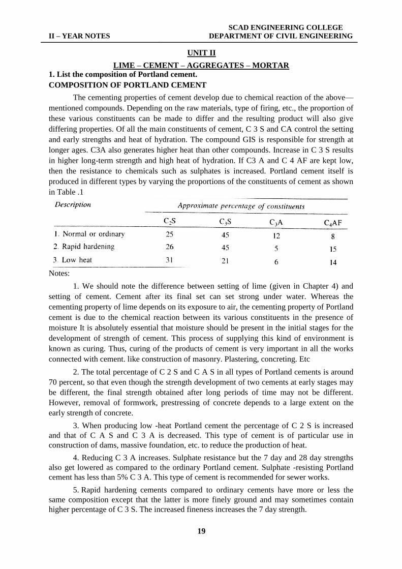


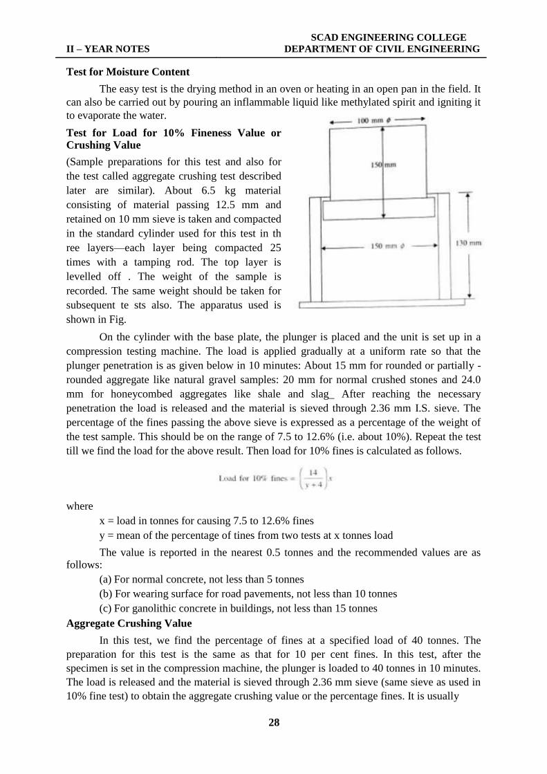


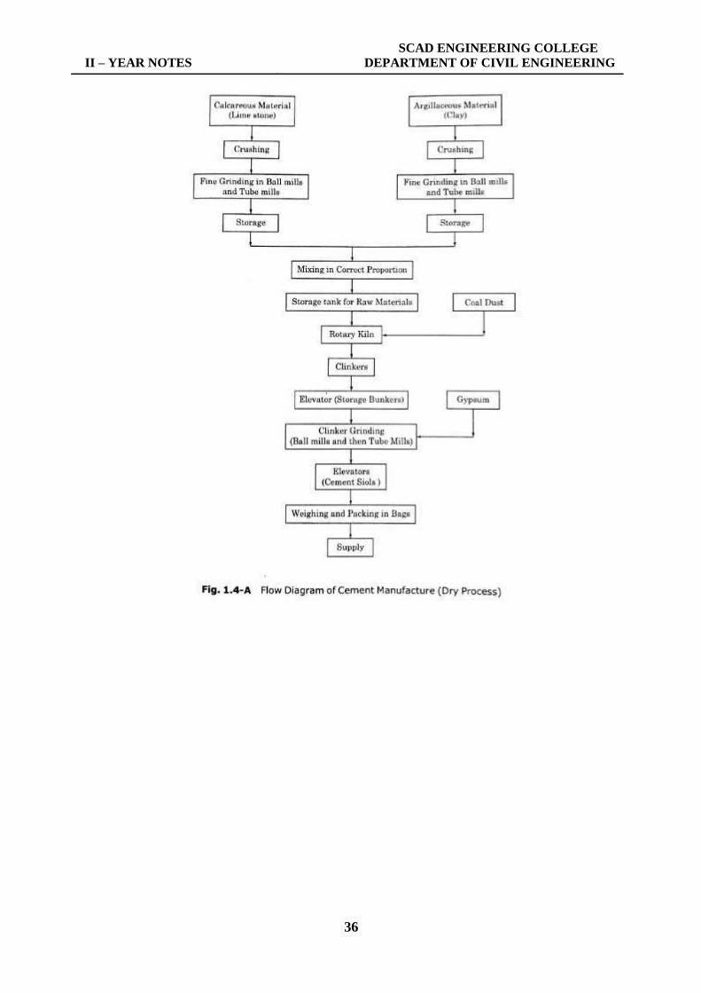


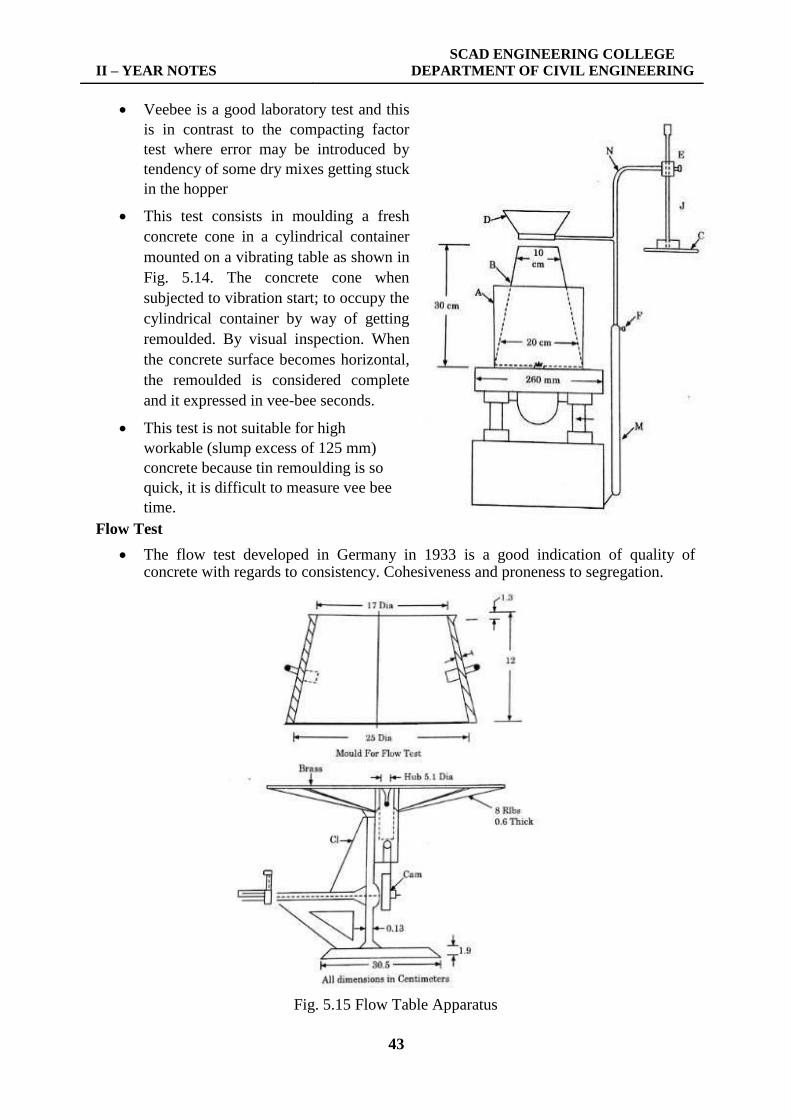


![INDEX [] · 2019-04-15 · INDEX ... index](https://static.documents.pub/doc/80x56/5e5bc6adf543e8499e5ad9a4/index-2019-04-15-index-index.jpg)


![index [] · index ... index](https://static.documents.pub/doc/80x56/5e33c50d475fc05b6d5265f9/index-index-index.jpg)


