48
2008 Developers Conference Taipei, Taiwan
| Date post: | 22-Oct-2015 |
| Category: |
Documents |
| Upload: | krishnendhu-prakasan |
| View: | 70 times |
| Download: | 5 times |

2008
Developers ConferenceTaipei, Taiwan

An Introduction to Consumer Electronics Control (CEC)
Quantum Data, Inc.

What is CEC? – Quick Facts
CEC stands for Consumer Electronics Control. It’s a one-wire bus (pin 13) that “snakes”
through an HDMI system - allowing products to pass messages to one another.
CEC runs at approx. 400Hz, so including flow control bits and idle timing requirements on the line, it can send approximately 30 bytes each second.
Commands need to be very efficient.
CEC: A Bit of History
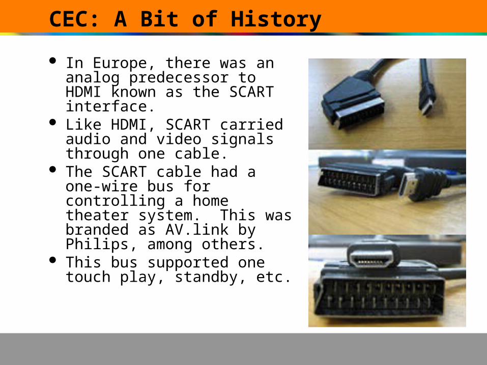
In Europe, there was an analog predecessor to HDMI known as the SCART interface.
Like HDMI, SCART carried audio and video signals through one cable.
The SCART cable had a one-wire bus for controlling a home theater system. This was branded as AV.link by Philips, among others.
This bus supported one touch play, standby, etc.
How To Find CEC Devices
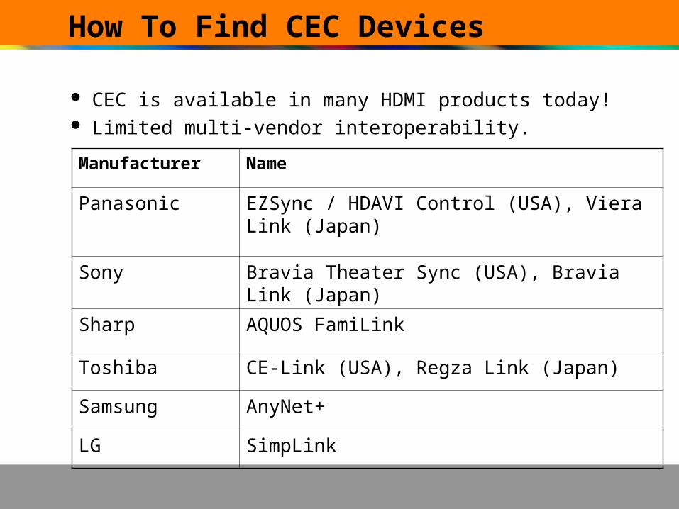
CEC is available in many HDMI products today! Limited multi-vendor interoperability.
Manufacturer Name
Panasonic EZSync / HDAVI Control (USA), Viera Link (Japan)
Sony Bravia Theater Sync (USA), Bravia Link (Japan)
Sharp AQUOS FamiLink
Toshiba CE-Link (USA), Regza Link (Japan)
Samsung AnyNet+
LG SimpLink

What is the benefit of CEC?
Today’s HDMI systems are comprised of separate components (digital set top boxes, audio receivers/amps, a DVD player, etc.), which are not always easy to configure & operate.
The general public has difficulty with the how/when/why to set up these devices in order to use them. The more devices, the more complex is the setup.
CEC is a solution to this problem! CEC uses signal routing to allow devices to be
configured across a system - rather than just point-to-point. Examples are one touch play and one touch record which greatly simplify the user experience.

CEC Messaging

CEC Messaging – Quick Facts
CEC messages generally consist of two functional categories:– Request – asking another device(s) to take action or to give
information (e.g. asking a device to play, go into standby, switch sources, or request a device’s physical address).
– Informative – status messages and messages describing where a devices is in a network (e.g. report physical address, report vendor ID).
CEC messages can also be grouped in terms of the intended target device:
– Directed Message - sent to a single CEC device.– Broadcast - sent to all devices in the CEC network.
CEC messages can be up to 16 blocks total (including the header and opcode blocks). If they were longer, they would impede access to the CEC bus due to the speed of the bus. (Sending 16 blocks successfully takes about 0.4s).
The shortest message that can be sent is the polling message, which is simply a start bit followed by a header block.
Devices must respond to a message in 1 second or less, but the desired response time is 200 msec.
CEC Messaging – Blocks and Frames
CEC Data BlockCEC Data Block
Information Bits End ofMessage
Acknowledgment
CEC Header BlockCEC Header Block
Logical Address ofInitiator
Logical Address of
Destination
End ofMessage
Acknowledgment
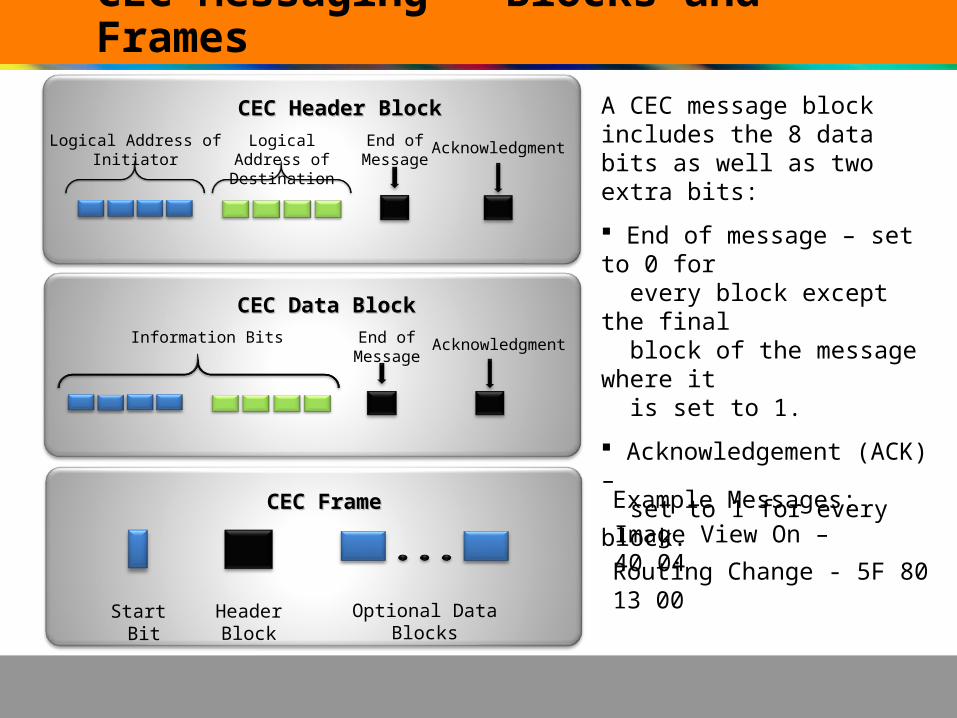
A CEC message block includes the 8 data bits as well as two extra bits:
End of message – set to 0 for every block except the final block of the message where it
is set to 1.
Acknowledgement (ACK) – set to 1 for every block.
CEC FrameCEC Frame
Start Bit
HeaderBlock
Optional DataBlocks
Image View On – 40 04
Routing Change - 5F 80 13 00
Example Messages:

CEC at Work

CEC at Work – One Touch Play
Image View On (40 04)
DVD DTV
DTV
AVR
DVD Game System STB-DVR
01 00:00:11.01 00:00:00.00 PLAYER1->TV CEC CEC IMAGE VIEW ON01 00:00:11.01 00:00:00.00 PLAYER1->TV CEC CEC IMAGE VIEW ON
02 00:00:11.07 00:00:00.60 PLAYER1->ALL CEC CEC ACTIVE SOURCE02 00:00:11.07 00:00:00.60 PLAYER1->ALL CEC CEC ACTIVE SOURCE
03 00:00:12.21 00:00:01.60 AUDIO->ALL CEC CEC REQUEST ACTIVE SRC03 00:00:12.21 00:00:01.60 AUDIO->ALL CEC CEC REQUEST ACTIVE SRC
04 00:00:18.41 00:00:06.20 PLAYER1->ALL CEC CEC ACTIVE SOURCE04 00:00:18.41 00:00:06.20 PLAYER1->ALL CEC CEC ACTIVE SOURCEActive Source (4F 82 11 00)
DVD ALL
Request Active Source(5F 85)
Request Active Source (5F 85)
DVD DTVAVR
Active Source (4F 82 11 00)
DVD ALL
Request Active Source (0F 85)
ALLDTV
Active Source (4F 82 11 00)
DVD ALL
05 00:00:12.21 00:00:01.60 TV->ALL CEC CEC REQUEST ACTIVE SRC05 00:00:12.21 00:00:01.60 TV->ALL CEC CEC REQUEST ACTIVE SRC
06 00:00:18.41 00:00:06.20 PLAYER1->ALL CEC CEC ACTIVE SOURCE06 00:00:18.41 00:00:06.20 PLAYER1->ALL CEC CEC ACTIVE SOURCE
Device functions, actions, message simulation only, 3 ports AVR

CEC at Work – One Touch Play
DTV
AVR
DVD Game System STB-DVR
01 00:00:11.01 00:00:00.00 TUNER->TV CEC CEC IMAGE VIEW ON01 00:00:11.01 00:00:00.00 TUNER->TV CEC CEC IMAGE VIEW ON
02 00:00:11.07 00:00:00.60 TV->TUNER CEC CEC SET STREAM PATH02 00:00:11.07 00:00:00.60 TV->TUNER CEC CEC SET STREAM PATH
03 00:00:12.21 00:00:01.60 TUNER->ALL CEC CEC ACTIVE SOURCE03 00:00:12.21 00:00:01.60 TUNER->ALL CEC CEC ACTIVE SOURCE
Image View On (30 04)
Active Source (3F 82 13 00)
STB-DVR DTV
STB-DVR ALL
Set Stream Path (03 86 13 00)
Ch. 2Ch. 3Ch. 4
DTV Remote
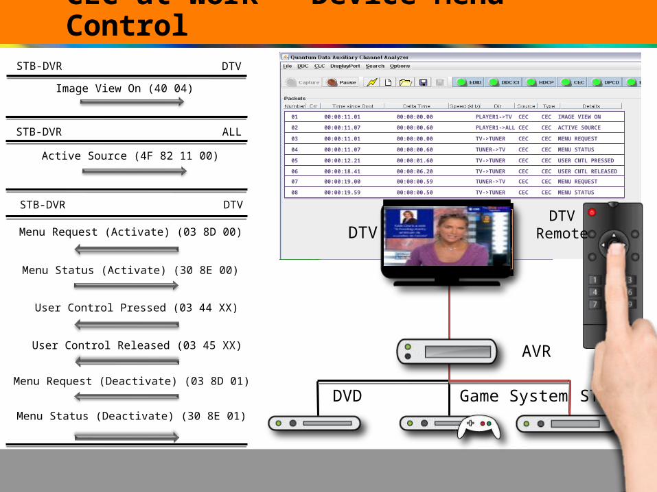
CEC at Work – Device Menu Control
DTV
AVR
DVD Game System STB-DVR
Menu Status (Activate) (30 8E 00)
User Control Released (03 45 XX)
User Control Pressed (03 44 XX)
STB-DVR DTV
Menu Request (Activate) (03 8D 00)
Menu Request (Deactivate) (03 8D 01)
Menu Status (Deactivate) (30 8E 01)
Ch. 2Ch. 3Ch. 4
Image View On (40 04)
STB-DVR DTV
Active Source (4F 82 11 00)
STB-DVR ALL
01 00:00:11.01 00:00:00.00 PLAYER1->TV CEC CEC IMAGE VIEW ON01 00:00:11.01 00:00:00.00 PLAYER1->TV CEC CEC IMAGE VIEW ON
02 00:00:11.07 00:00:00.60 PLAYER1->ALL CEC CEC ACTIVE SOURCE02 00:00:11.07 00:00:00.60 PLAYER1->ALL CEC CEC ACTIVE SOURCE
DTVRemote
03 00:00:11.01 00:00:00.00 TV->TUNER CEC CEC MENU REQUEST03 00:00:11.01 00:00:00.00 TV->TUNER CEC CEC MENU REQUEST
04 00:00:11.07 00:00:00.60 TUNER->TV CEC CEC MENU STATUS04 00:00:11.07 00:00:00.60 TUNER->TV CEC CEC MENU STATUS
05 00:00:12.21 00:00:01.60 TV->TUNER CEC CEC USER CNTL PRESSED05 00:00:12.21 00:00:01.60 TV->TUNER CEC CEC USER CNTL PRESSED
06 00:00:18.41 00:00:06.20 TV->TUNER CEC CEC USER CNTL RELEASED06 00:00:18.41 00:00:06.20 TV->TUNER CEC CEC USER CNTL RELEASED
07 00:00:19.00 00:00:00.59 TUNER->TV CEC CEC MENU REQUEST07 00:00:19.00 00:00:00.59 TUNER->TV CEC CEC MENU REQUEST
08 00:00:19.59 00:00:00.50 TV->TUNER CEC CEC MENU STATUS08 00:00:19.59 00:00:00.50 TV->TUNER CEC CEC MENU STATUS

CEC at Work: One Touch Record
AVR
DVD Game System STB-DVR
DTV STB-DVR
Record TV Screen (10 0F)
Record Status [Recording Digital Service] (10 0A 02)
Record ON [Digital Service ID] (01 09 02)
01 00:00:18.41 00:00:00.00 RECORDER->TV CEC CEC RECORD TV SCREEN01 00:00:18.41 00:00:00.00 RECORDER->TV CEC CEC RECORD TV SCREEN
02 00:00:69.51 00:00:51.10 TV->RECORDER CEC CEC RECORD ON02 00:00:69.51 00:00:51.10 TV->RECORDER CEC CEC RECORD ON
03 00:00:69.71 00:00:00.20 RECORDER->TV CEC CEC RECORD STATUS03 00:00:69.71 00:00:00.20 RECORDER->TV CEC CEC RECORD STATUS
DTV
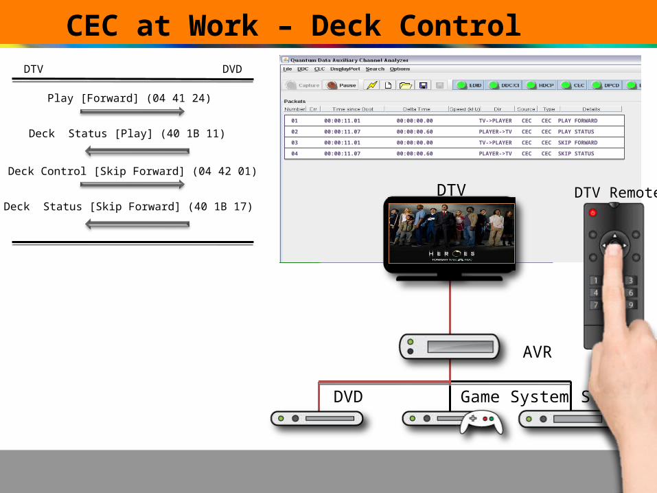
CEC at Work – Deck Control
DTV
AVR
DVD Game System STB-DVR
01 00:00:11.01 00:00:00.00 TV->PLAYER CEC CEC PLAY FORWARD01 00:00:11.01 00:00:00.00 TV->PLAYER CEC CEC PLAY FORWARD
02 00:00:11.07 00:00:00.60 PLAYER->TV CEC CEC PLAY STATUS02 00:00:11.07 00:00:00.60 PLAYER->TV CEC CEC PLAY STATUS
Play [Forward] (04 41 24)
DTV DVD
Deck Status [Play] (40 1B 11)
DTV Remote
Deck Control [Skip Forward] (04 42 01)
Deck Status [Skip Forward] (40 1B 17)
03 00:00:11.01 00:00:00.00 TV->PLAYER CEC CEC SKIP FORWARD03 00:00:11.01 00:00:00.00 TV->PLAYER CEC CEC SKIP FORWARD
04 00:00:11.07 00:00:00.60 PLAYER->TV CEC CEC SKIP STATUS04 00:00:11.07 00:00:00.60 PLAYER->TV CEC CEC SKIP STATUS
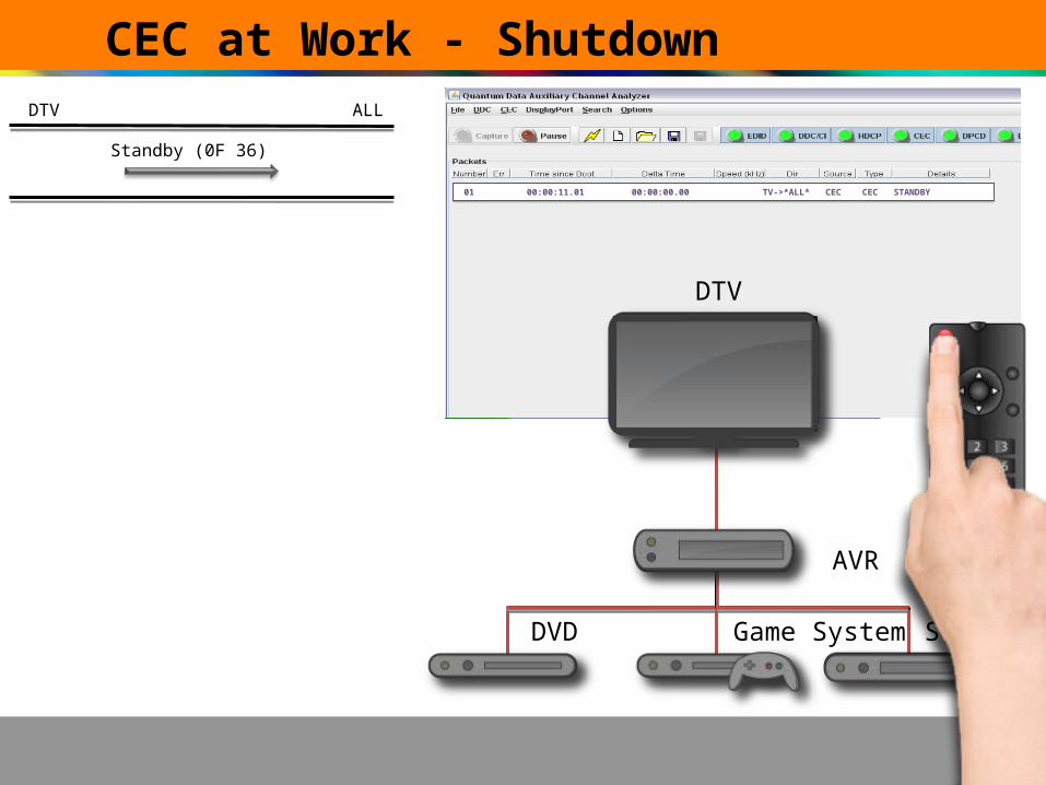
CEC at Work - Shutdown
DTV
AVR
DVD Game System STB-DVR
01 00:00:11.01 00:00:00.00 TV->*ALL* CEC CEC STANDBY01 00:00:11.01 00:00:00.00 TV->*ALL* CEC CEC STANDBY
Standby (0F 36)
DTV ALL

CEC Addressing

CEC Addressing
CEC assumes that all AV source products in a system are directly or indirectly connected to a “root” display (DTV).
HDMI connections form an upside-down tree, with a display as the “root”, switches as “branches”, and various source products as “leaf” nodes.
There are two types of addressing:– Logical– Physical

Logical Addressing
Logical addressing is what CEC uses to identify a specific instance of a specific device type. When messages are sent over CEC, the logical address identifies both the sender (“Initiator”) and intended receiver (“Follower”) of the message.
Logical addressing is done with nybbles (4-bit numbers, allowing for addresses from 0-15). Because of this, the header blocks are simply in “to, from” format – the first four bits sent are the address of the initiator (or sender), while the latter four bits are the follower’s (receiver’s) address.
CEC Header BlockCEC Header BlockLogical Address of
InitiatorLogical Address of
FollowerEnd of
MessageAcknowledgment

Logical Addressing (continued)
Logical addresses are split among device types:– 0 is a TV– 1,2 & 9 are recorders (HDD, DVD, BD, etc.)– 3,6,7 & 10 are tuner devices (i.e. set-top boxes)– 4,8 & 11 are players (DVD, VCR, Blu-Ray, etc.)– 5 is an audio system– 12 & 13 are reserved– 14 is a wild-card– 15 means “Unregistered” if it’s the initiator address,
“Broadcast” if it’s the follower address.

Physical Addressing
Physical addressing describes the topology, i.e. what devices are between the CEC device and the TV, and through what inputs it is connected.
Physical addressing is a required feature for ALL HDMI devices (regardless of whether or not they support CEC), and is essential for routing control, among other things.

Physical Addressing Description
A TV (that does not have HDMI outputs) will use physical address [0.0.0.0]. Any device with an HDMI output will have an address that contains at least one non-zero number, which is grabbed from the HDMI vendor specific data block (VSDB) of the sink device’s EDID.
Devices with both a source and a sink must read the physical address from the EDID of the sink device that it is attached to, and configure its own EDIDs on its sink ports so that they contain the proper physical addresses.
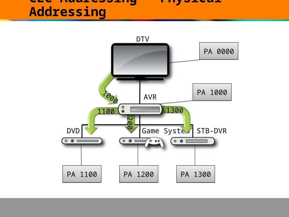
CEC Addressing – Physical Addressing
DTV
AVR
DVD Game System STB-DVR
PA 1100PA 1100 PA 1200PA 1200 PA 1300PA 1300
PA 1000PA 1000
PA 0000PA 0000
1100 1200
1000
1300

Physical Addressing – VSDB of EDID
1100
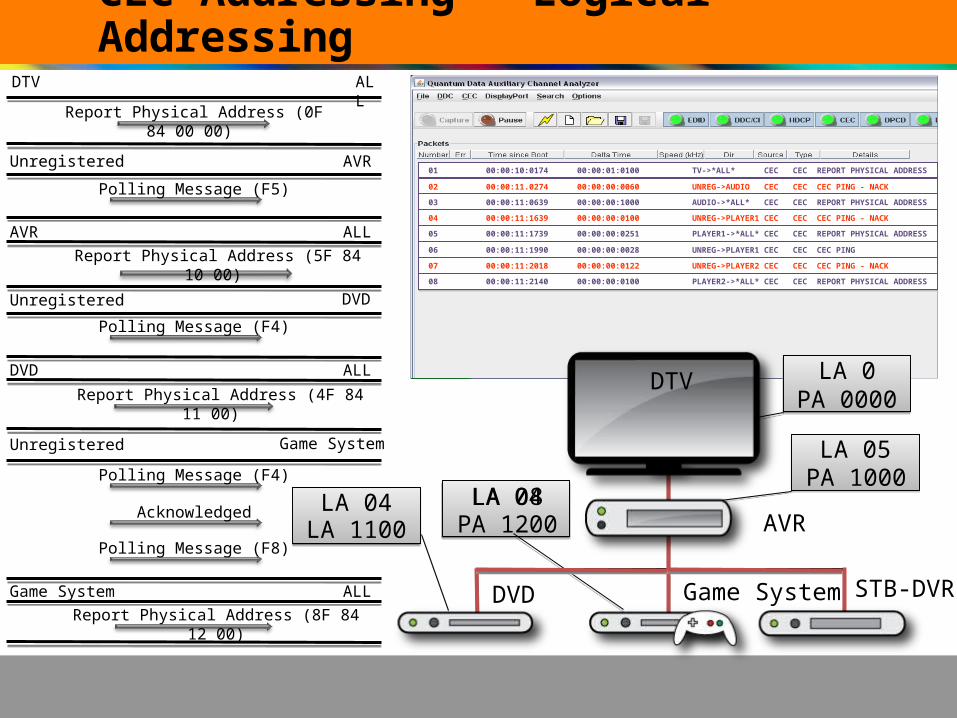
CEC Addressing – Logical Addressing
DVD Game System STB-DVR
LA 04LA 04
LA 05LA 05
LA 0PA 0000
LA 0PA 0000
LA 1100LA 04LA 08
PA 1000
Polling Message (F5)
Unregistered AVR
Report Physical Address (0F 84 00 00)
Report Physical Address (5F 84 10 00)
Polling Message (F4)
Unregistered DVD
Report Physical Address (4F 84 11 00)
Polling Message (F8)
Unregistered Game System
Report Physical Address (8F 84 12 00)
01 00:00:10:0174 00:00:01:0100 TV->*ALL* CEC CEC REPORT PHYSICAL ADDRESS01 00:00:10:0174 00:00:01:0100 TV->*ALL* CEC CEC REPORT PHYSICAL ADDRESS
02 00:00:11.0274 00:00:00:0060 UNREG->AUDIO CEC CEC CEC PING - NACK02 00:00:11.0274 00:00:00:0060 UNREG->AUDIO CEC CEC CEC PING - NACK
03 00:00:11:0639 00:00:00:1000 AUDIO->*ALL* CEC CEC REPORT PHYSICAL ADDRESS03 00:00:11:0639 00:00:00:1000 AUDIO->*ALL* CEC CEC REPORT PHYSICAL ADDRESS
04 00:00:11:1639 00:00:00:0100 UNREG->PLAYER1 CEC CEC CEC PING - NACK04 00:00:11:1639 00:00:00:0100 UNREG->PLAYER1 CEC CEC CEC PING - NACK
05 00:00:11:1739 00:00:00:0251 PLAYER1->*ALL* CEC CEC REPORT PHYSICAL ADDRESS05 00:00:11:1739 00:00:00:0251 PLAYER1->*ALL* CEC CEC REPORT PHYSICAL ADDRESS
06 00:00:11:1990 00:00:00:0028 UNREG->PLAYER1 CEC CEC CEC PING06 00:00:11:1990 00:00:00:0028 UNREG->PLAYER1 CEC CEC CEC PING
AVR
Polling Message (F4)
AcknowledgedPA 1200
07 00:00:11:2018 00:00:00:0122 UNREG->PLAYER2 CEC CEC CEC PING - NACK07 00:00:11:2018 00:00:00:0122 UNREG->PLAYER2 CEC CEC CEC PING - NACK
08 00:00:11:2140 00:00:00:0100 PLAYER2->*ALL* CEC CEC REPORT PHYSICAL ADDRESS08 00:00:11:2140 00:00:00:0100 PLAYER2->*ALL* CEC CEC REPORT PHYSICAL ADDRESS
AVR ALL
DVD ALL
Game System ALL
DTV ALL
DTV

01 00:00:10:0174 00:00:01:0100 TV->ALL CEC CEC REPORT PHYSICAL ADDRESS01 00:00:10:0174 00:00:01:0100 TV->ALL CEC CEC REPORT PHYSICAL ADDRESS
02 00:00:11.0274 00:00:00:0060 UNREG->AUDIO CEC CEC CEC PING - NACK02 00:00:11.0274 00:00:00:0060 UNREG->AUDIO CEC CEC CEC PING - NACK
03 00:00:11:0639 00:00:00:1000 AUDIO->ALL CEC CEC REPORT PHYSICAL ADDRESS03 00:00:11:0639 00:00:00:1000 AUDIO->ALL CEC CEC REPORT PHYSICAL ADDRESS
04 00:00:11:1639 00:00:00:0100 UNREG->PLAYER1 CEC CEC CEC PING - NACK04 00:00:11:1639 00:00:00:0100 UNREG->PLAYER1 CEC CEC CEC PING - NACK
05 00:00:11:1739 00:00:00:0251 PLAYER1->ALL CEC CEC REPORT PHYSICAL ADDRESS05 00:00:11:1739 00:00:00:0251 PLAYER1->ALL CEC CEC REPORT PHYSICAL ADDRESS
06 00:00:11:1990 00:00:00:0028 UNREG->PLAYER1 CEC CEC CEC PING06 00:00:11:1990 00:00:00:0028 UNREG->PLAYER1 CEC CEC CEC PING
07 00:00:11:2018 00:00:00:0112 UNREG->PLAYER2 CEC CEC CEC PING - NACK07 00:00:11:2018 00:00:00:0112 UNREG->PLAYER2 CEC CEC CEC PING - NACK
Polling Message (F3)
Report Physical Address (3F 84 13 00)
Polling Message (F1)
Report Physical Address (1F 84 13 00)
LA 03LA 01
DVD Game System STB-DVR
DTV
AVR
Unregistered STB-DVR
Unregistered STB-DVR
LA 04LA 04
LA 05LA 05
LA 0PA 0000
LA 0PA 0000
LA 1100
LA 08PA 1000
PA 1200PA 1300
DTV
CEC Addressing – Logical Addressing
08 00:00:11:2140 00:00:00:0100 PLAYER2->ALL CEC CEC REPORT PHYSICAL ADDRESS08 00:00:11:2140 00:00:00:0100 PLAYER2->ALL CEC CEC REPORT PHYSICAL ADDRESS
09 00:00:11:2230 00:00:00:0600 UNREG->TUNER CEC CEC CEC PING - NACK09 00:00:11:2230 00:00:00:0600 UNREG->TUNER CEC CEC CEC PING - NACK
10 00:00:11:2830 00:00:00:0164 TUNER->ALL CEC CEC REPORT PHYSICAL ADDRESS10 00:00:11:2830 00:00:00:0164 TUNER->ALL CEC CEC REPORT PHYSICAL ADDRESS
11 00:00:11:2994 00:00:00:0600 UNREG->RECORD CEC CEC CEC PING - NACK11 00:00:11:2994 00:00:00:0600 UNREG->RECORD CEC CEC CEC PING - NACK
12 00:00:11:3594 00:00:00:0000 RECORD->ALL CEC CEC REPORT PHYSICAL ADDRESS12 00:00:11:3594 00:00:00:0000 RECORD->ALL CEC CEC REPORT PHYSICAL ADDRESS
STB-DVR ALL
STB-DVR ALL
DTV: PA 000 LA 0
AVR: PA 1000 LA 05
DVD: PA 1100 LA 04
Game System: PA 12 00 LA 08
STB-DVR: PA 1300 LA 03/LA 01

CEC Addressing – Sample Network

CEC Physical Layer

Physical Information
CEC is pin 13 on the HDMI cable. It shares a common ground with DDC.
CEC idles in a high-impedance state (the line shows a voltage between +2.5 and +3.63V).
During a message, the line will be pulled down to between 0 and +0.6V (“low-impedance”).

Physical Information (continued)
CEC supports nine devices on the bus simultaneously (potentially more if good cabling is used). The limitation is due to a network limit on capacitance of 7200pF (allowing for 100pF per device and 700pF per cable).
However, there are only 15 valid CEC logical addresses, so having a limitation of nine devices would rarely be a problem in real-world applications.
The CEC line is in use when there is a device pulling the line low. All timing is derived from the high to low transitions.

Physical Information – Bit Timing
Start Bits
Logical “0” and “1”
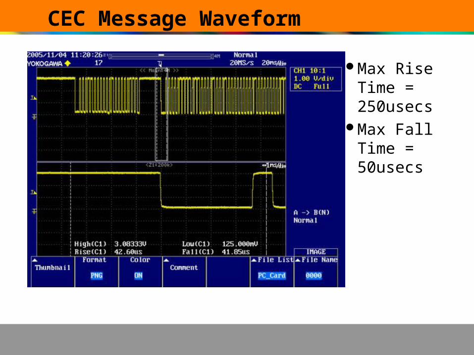
CEC Message Waveform
Max Rise Time = 250usecs
Max Fall Time = 50usecs

CEC Bus Control

CEC Bus Control - Retransmission
Retransmission can occur for many reasons:– A device could be holding the CEC bus low when
the initiator expects it high, causing a bus error.– A device sends a message and does not receive
the expected acknowledgement.– A device loses arbitration (retry).
Retransmission should not occur if there is sufficient indication that the follower does not support the message being sent.

CEC Bus Control - Acknowledgement
Directed messages– Intended for a single device– ACK is set as a “logical 1”– Set to “logical 0” by the follower to acknowledge
Broadcast messages– Intended for all devices– ACK is set as a “logical 1”– Must be kept as a “logical 1” by all devices– A “logical 0” is a NACK
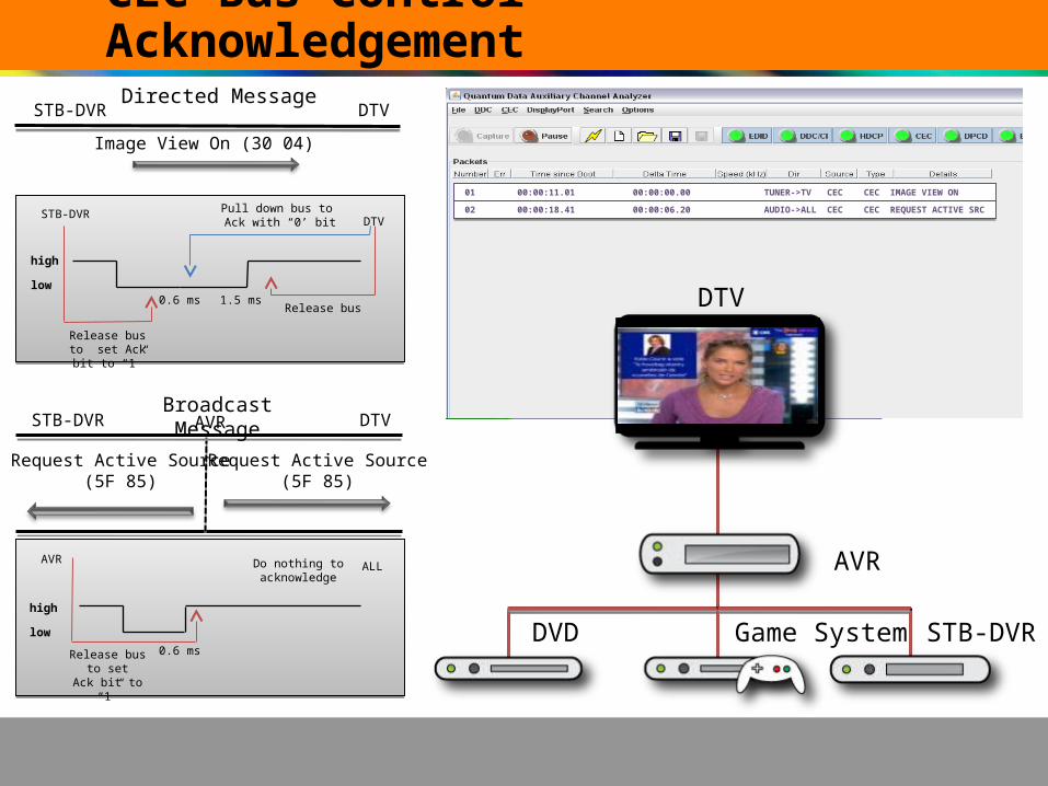
CEC Bus Control - Acknowledgement
DTV
AVR
DVD Game System STB-DVR
01 00:00:11.01 00:00:00.00 TUNER->TV CEC CEC IMAGE VIEW ON01 00:00:11.01 00:00:00.00 TUNER->TV CEC CEC IMAGE VIEW ON
02 00:00:18.41 00:00:06.20 AUDIO->ALL CEC CEC REQUEST ACTIVE SRC02 00:00:18.41 00:00:06.20 AUDIO->ALL CEC CEC REQUEST ACTIVE SRC
Image View On (30 04)
Request Active Source(5F 85)
Request Active Source(5F 85)
STB-DVR DTV
DTVAVR
high
low0.6 ms 1.5 ms
Release bus to set Ack bit to “1”
Pull down bus to Ack with “0’ bit
STB-DVRDTV
0.6 msRelease bus to set
Ack bit to “1”
AVRALL
Release bus
Do nothing toacknowledge
Directed Message
Broadcast Message
high
low
STB-DVR

CEC Bus Control – No Acknowledgement
DTV
AVR
DVD Game System STB-DVR
01 00:00:11.01 00:00:00.00 TUNER->TV CEC CEC UNACKNOWLEDGED01 00:00:11.01 00:00:00.00 TUNER->TV CEC CEC UNACKNOWLEDGED
02 00:00:18.41 00:00:06.20 AUDIO->ALL CEC CEC UNACKNOWLEDGED02 00:00:18.41 00:00:06.20 AUDIO->ALL CEC CEC UNACKNOWLEDGED
Image View On (30 04)
Request Active Source(5F 85)
Request Active Source(5F 85)
STB-DVR DTV
DTVAVR
high
low0.6 ms 1.5 ms
Pull down to 0 toNack
STB-DVRDTV
Release bus
high
low0.6 msRelease bus to
set Ack bit to “1”
AVRDTV
Do nothing to Nack
Release bus to set Ack bit to “1”
Broadcast Message
Directed Message
STB-DVR

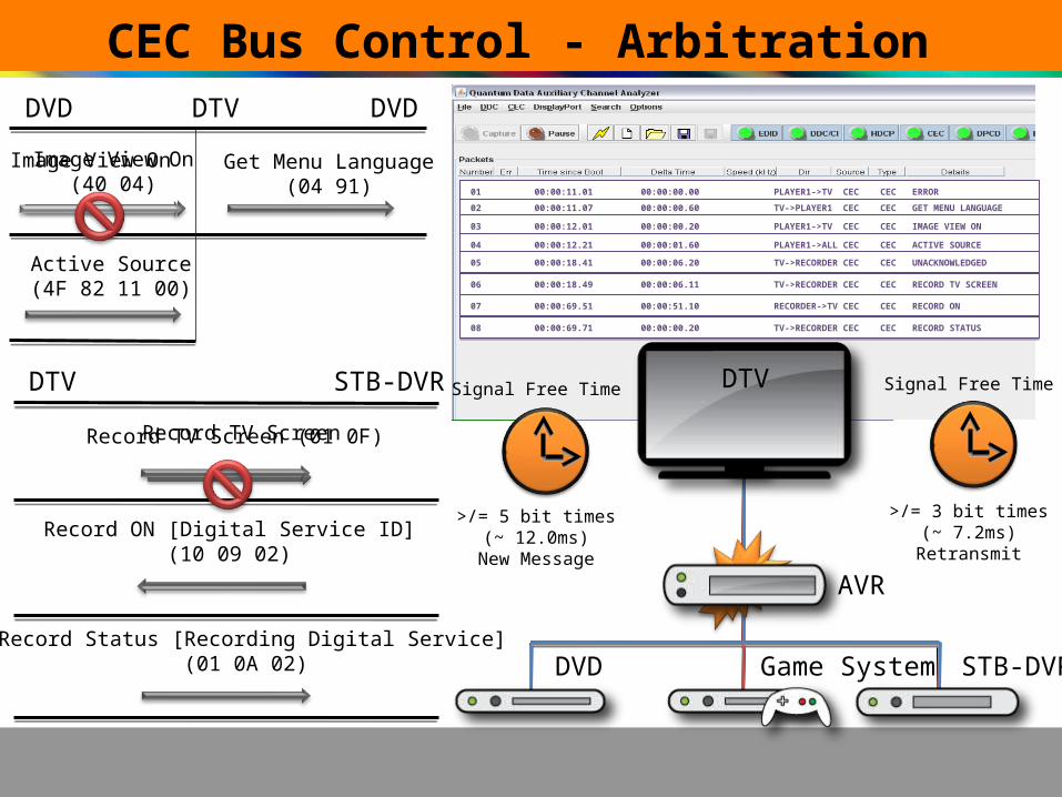
CEC Bus Control - Arbitration
Since CEC is a single wire for all devices, it is sometimes the case that two devices want to use the CEC line at the same time.
Arbitration check begins with leading edge of start bit and continues to end of initiator address.
Priority given to the device with the lowest logical address. The TV (logical address 0) has priority over all other devices.
If a device is already using the CEC line, the devices that would like to use it must wait until “signal free time” has been met (the device has stopped using the line for a defined length of time).
– At least 3 bit periods (7.2ms) in the case of a device trying to resend a message.
– At least 5 bit periods (12.0ms) for a new device wishing to send a message
– At least 7 bit periods (16.8ms) for the same device wishing to send a new message.
Signal free time is defined from the START of the final bit being sent (the high to low transition).
CEC Bus Control - Arbitration
Image View On(40 04)
DVD DTV
AVR
DVD Game System STB-DVR
Active Source(4F 82 11 00)
DVD
Get Menu Language(04 91)
DTV STB-DVR
Record Status [Recording Digital Service](01 0A 02)
Record ON [Digital Service ID] (10 09 02)
01 00:00:11.01 00:00:00.00 PLAYER1->TV CEC CEC ERROR01 00:00:11.01 00:00:00.00 PLAYER1->TV CEC CEC ERROR
02 00:00:11.07 00:00:00.60 TV->PLAYER1 CEC CEC GET MENU LANGUAGE02 00:00:11.07 00:00:00.60 TV->PLAYER1 CEC CEC GET MENU LANGUAGE
03 00:00:12.01 00:00:00.20 PLAYER1->TV CEC CEC IMAGE VIEW ON03 00:00:12.01 00:00:00.20 PLAYER1->TV CEC CEC IMAGE VIEW ON
04 00:00:12.21 00:00:01.60 PLAYER1->ALL CEC CEC ACTIVE SOURCE04 00:00:12.21 00:00:01.60 PLAYER1->ALL CEC CEC ACTIVE SOURCE
Record TV ScreenRecord TV Screen (01 0F)
Image View On
05 00:00:18.41 00:00:06.20 TV->RECORDER CEC CEC UNACKNOWLEDGED05 00:00:18.41 00:00:06.20 TV->RECORDER CEC CEC UNACKNOWLEDGED
06 00:00:18.49 00:00:06.11 TV->RECORDER CEC CEC RECORD TV SCREEN06 00:00:18.49 00:00:06.11 TV->RECORDER CEC CEC RECORD TV SCREEN
07 00:00:69.51 00:00:51.10 RECORDER->TV CEC CEC RECORD ON07 00:00:69.51 00:00:51.10 RECORDER->TV CEC CEC RECORD ON
08 00:00:69.71 00:00:00.20 TV->RECORDER CEC CEC RECORD STATUS08 00:00:69.71 00:00:00.20 TV->RECORDER CEC CEC RECORD STATUS
Signal Free Time
>/= 3 bit times(~ 7.2ms)
Retransmit
Signal Free Time
>/= 5 bit times(~ 12.0ms)
New Message
DTV

Verifying CEC Implementation

Verifying the CEC Implementation
Compliance testing– In-house using compliance test tools– Plugfests (CEA and ETSI)– HDMI Authorized Test Centers
Interoperability testing (multi-vendor)– In-house – Plugfests

Verifying the CEC Implementation
Tools you will need– CEC debug tools used during development– CEC bus monitor– CEC compliance test application (Quantum Data
Test Management Environment is the recommended test tool in the HDMI CTS)
– Test fixtures
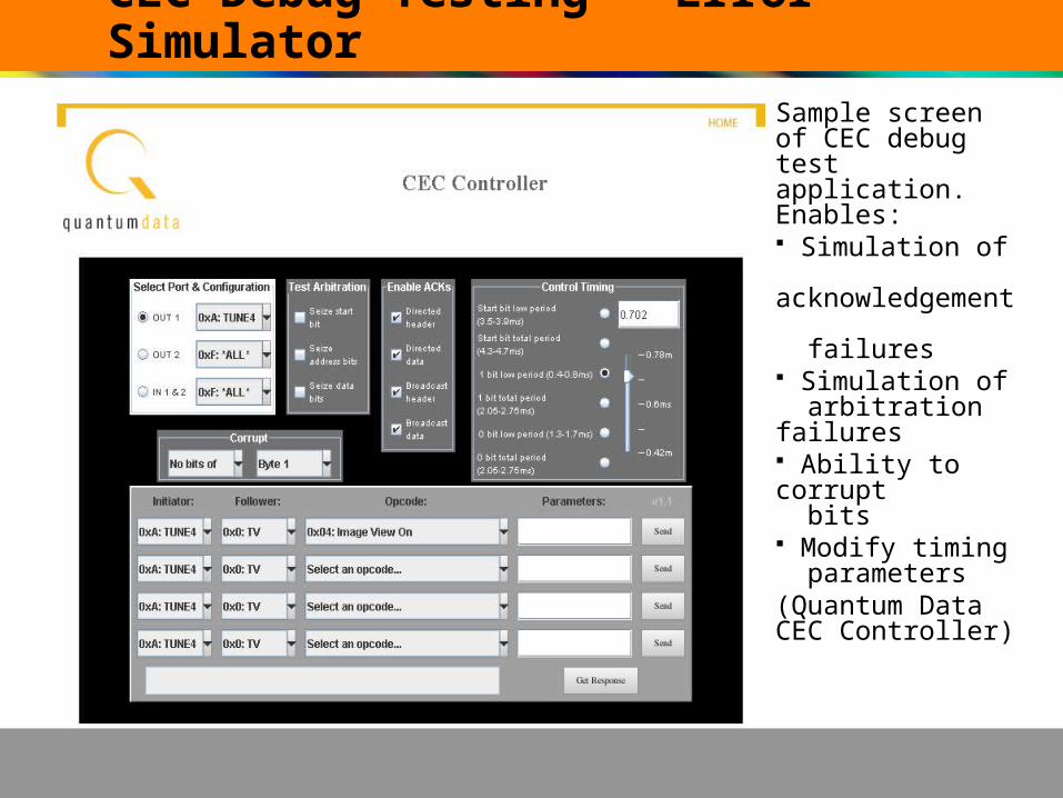
CEC Debug Testing – Error SimulatorSample screen of CEC debug test application. Enables: Simulation of acknowledgement failures Simulation of arbitration failures Ability to corrupt bits Modify timing parameters(Quantum Data CEC Controller)

CEC Debug Testing – Message LoggerSample screen of CEC Transaction logger: Logs CEC trans- actions during compliance test Logs CEC trans- actions during debug testing Shows detailed timing Shows acknow- ledgement and other errors(Quantum Data Auxiliary Channel Analyzer)

CEC Compliance Testing – CDF EntrySample of a CEC compliance test application showing CDF definition: Enables importing CDF from comma separated value file for fast CDF definition Enables definition of CDF parameters for new devices through GUI Supports saving CDFs for later use(Quantum Data CEC Compliance Application)
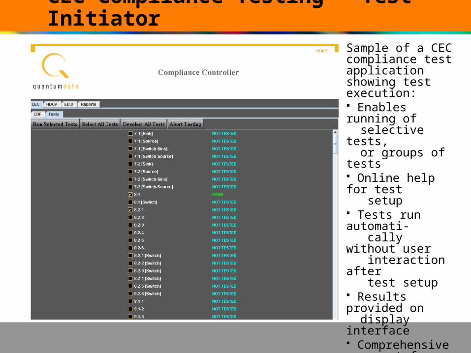
CEC Compliance Testing - Test InitiatorSample of a CEC compliance test application showing test execution: Enables running of selective tests, or groups of tests Online help for test setup Tests run automati- cally without user interaction after test setup Results provided on display interface Comprehensive report for all tests that can printed or emailed.(Quantum Data CEC Compliance Application)

For more information…
Quantum Data has prepared an educational whitepaper and a video on CEC that provides some further examples: http://www.quantumdata.com/

Thank You…
Presenter: Neal KendallTechnical consultant: Jeff Stenhouse
Animation & Graphics: Robert Watson


