Up to 5m Up to 7m Up to 5m Up to 7m Up to 5m Up to 5m In open plan areas For best coverage the PIRs should be spaced every 5m in either direction PIR Strong detection zone Secondary detection zone Strong detection zone e.g. person moving arm Secondary detection zone e.g. person walking (less sensitive when walking straight towards PIR switch) For optimum coverage recommended mounting height between 2.4 and 5m. PIR Quad detector gives 124 detection areas within the zone. Plan view of detection zone Several PIR occupancy switches Perspective view of detection zone Detection diagrams This range of energy saving products is designed for the automatic switching of a wide variety of load types. These products include a person detector and an adjustable photocell override. Designed for mounting on solid ceilings. They are hard wired and can be mounted on a square pattress box. Product options include: ● PIR presence detector switches ● PIR absence detector switches ● PIR switches with step down illuminance ● Low voltage variants. CEILING SURFACE PIR OCCUPANCY SWITCHES 24 www.danlers.co.uk A - Dimensions in mm plan side 22 86 86 B - Dimensions in mm plan side 53 86 86 C - Dimensions in mm plan side 22 86 86 SPECIFICATION Detection zone: 360° Max. detection area: 7m diameter at 2.4m mounting height Max. mounting height: 5m Photocell range: 30-1000 lux and inactive Time lag range: 10 seconds to 40 minutes in 9 steps Dimensions: See diagrams below LOADING 6 amps (1500W) Resistive 6 amps (1500W) Fluorescent 3 amps (750W) Electronic or wire wound transformer 2 amps (500W) LED Drivers and LED lamps and fittings 2 amps (500W) CFL or 2D lamps 1 amp (250W) Fans Minimum Load: 2W resistive. 5 YEAR WARRANTY - MADE IN THE U.K.
Transcript
Up to 5m
Up to 7m
Up to 5m
Up to 7m Up to 5m
Up to5m
In open plan areasFor best coverage the PIRs should be spaced every 5m in either directionPIR
Strong detection zone
Secondary detection zone
Strong detection zone e.g. person moving arm
Secondary detection zone e.g. person walking (less sensitive when walking straight towards PIR switch)
For optimum coverage recommended mounting height between 2.4 and 5m.
PIR Quad detector gives 124 detection areas within the zone.
Plan view of detection zone Several PIR occupancy switchesPerspective view of detection zone
Detection diagrams
This range of energy saving products is designed for the automatic switching of a wide variety of load types.
These products include a person detector and an adjustable photocell override. Designed for mounting on solid ceilings. They are hard wired and can be mounted on a square pattress box.
Product options include:
● PIR presence detector switches
● PIR absence detector switches
● PIR switches with step down illuminance
● Low voltage variants.
CEILING SURFACE PIR OCCUPANCY SWITCHES
24 www.danlers.co.uk
A - Dimensions in mm
plan
side
22
86
86
plan
side
53
86
86
B - Dimensions in mm
plan
side
22
86
86
plan
side
53
86
86
C - Dimensions in mm
plan
side
22
86
86
plan
side
53
86
86
SPECIFICATION
Detection zone: 360°
Max. detection area: 7m diameter at 2.4m mounting height
Max. mounting height: 5m
Photocell range: 30-1000 lux and inactive
Time lag range: 10 seconds to 40 minutes in 9 steps
Dimensions: See diagrams below
LOADING
6 amps (1500W) Resistive6 amps (1500W) Fluorescent 3 amps (750W) Electronic or wire wound transformer2 amps (500W) LED Drivers and LED lamps and fi ttings2 amps (500W) CFL or 2D lamps1 amp (250W) FansMinimum Load: 2W resistive. 5 YEAR WARRANTY - MADE IN THE U.K.
N
L
load
Presence PIR
optional manual wall switch for overriding off
Single control
230 VAC
alternative position for optional wall switch (see “Start-up Mode” page 6)SL
N
L
load
optional manual wall switch for overriding off
A few Presence PIRs
230 VAC
A few controls wired in parallel
alternative position for optional wall switch (see “Start-up Mode” page 6)
SL SL SL
25.1. Wiring diagrams Presence PIR
L
N
load
Single control
230 VAC
L
L
Nload
230 VAC
A few controls wired in parallel
Mains rated retractive wall switch or rocker wall switch (toggled)
L
L
AB SLN
Mains rated retractive wall switch or rocker wall switch (toggled)
25.2. Wiring diagrams Absence PIR and Short Visit PIR
25.3. Wiring diagram Step Down Illuminance PIR
CEILING SURFACE PIR OCCUPANCY SWITCHES
Telephone: +44(0)1249 443377 25
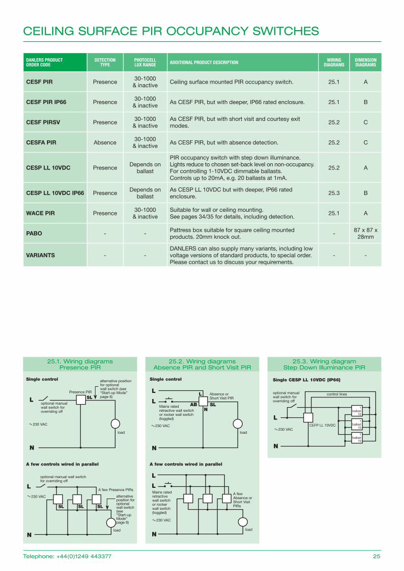
DANLERS PRODUCT ORDER CODE
DETECTION TYPE
PHOTOCELL LUX RANGE ADDITIONAL PRODUCT DESCRIPTION WIRING
DIAGRAMSDIMENSION DIAGRAMS
CESF PIR Presence30-1000
& inactiveCeiling surface mounted PIR occupancy switch. 25.1 A
CESF PIR IP66 Presence30-1000
& inactiveAs CESF PIR, but with deeper, IP66 rated enclosure. 25.1 B
CESF PIRSV Presence30-1000
& inactiveAs CESF PIR, but with short visit and courtesy exit modes.
25.2 C
CESFA PIR Absence30-1000
& inactiveAs CESF PIR, but with absence detection. 25.2 C
CESP LL 10VDC PresenceDepends on
ballast
PIR occupancy switch with step down illuminance. Lights reduce to chosen set-back level on non-occupancy. For controlling 1-10VDC dimmable ballasts.Controls up to 20mA, e.g. 20 ballasts at 1mA.
25.2 A
CESP LL 10VDC IP66 PresenceDepends on
ballastAs CESP LL 10VDC but with deeper, IP66 rated enclosure.
25.3 B
WACE PIR Presence30-1000
& inactiveSuitable for wall or ceiling mounting. See pages 34/35 for details, including detection.
VARIANTS - -DANLERS can also supply many variants, including low voltage versions of standard products, to special order. Please contact us to discuss your requirements.
- -
Single CESP LL 10VDC (IP66)
L
N
1ballast
10
1ballast
10
1ballast
10
230 VACCEFP LL 10VDC
control linesoptional manual wall switch for overriding off
A few Absence or Short Visit PIRs
Absence or Short Visit PIR
Up to 5m
Up to 7m
Up to 5m
Up to 7m Up to 5m
Up to5m
In open plan areasFor best coverage the PIRs should be spaced every 5m in either directionPIR
Strong detection zone
Secondary detection zone
Strong detection zone e.g. person moving arm
Secondary detection zone e.g. person walking (less sensitive when walking straight towards PIR switch)
For optimum coverage recommended mounting height between 2.4 and 5m.
PIR Quad detector gives 124 detection areas within the zone.
Plan view of detection zone Several PIR occupancy switchesPerspective view of detection zone
Detection diagrams
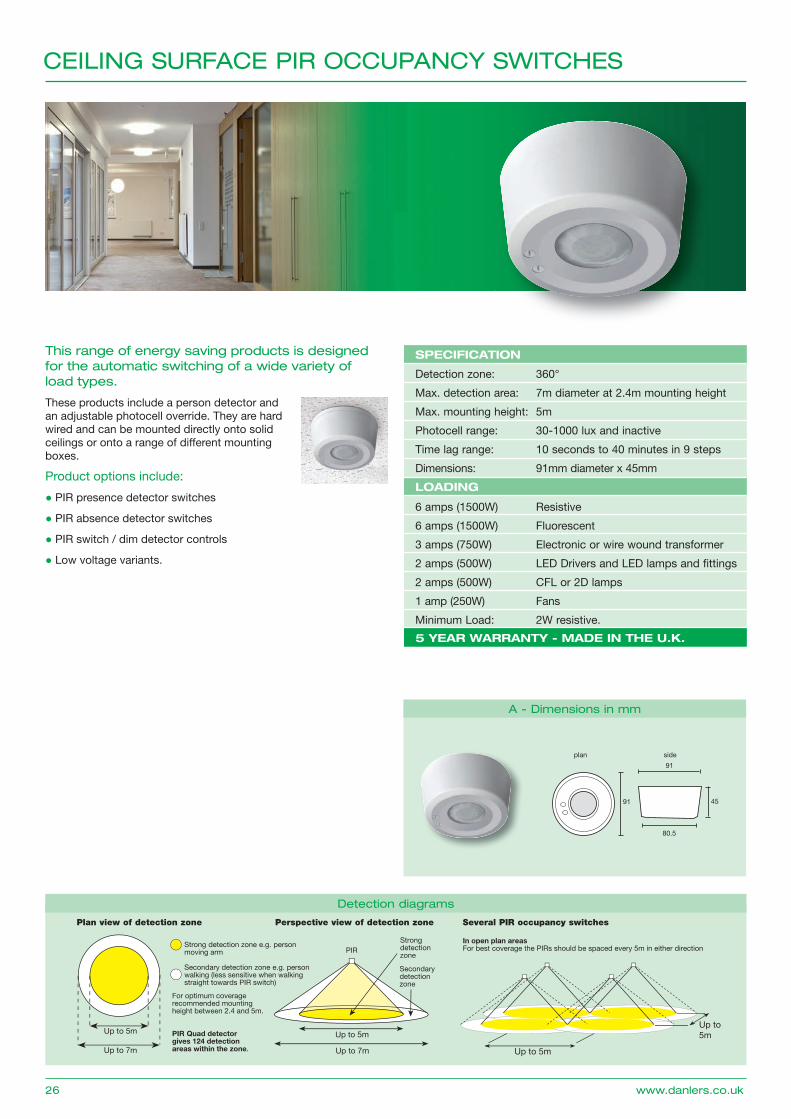
This range of energy saving products is designed for the automatic switching of a wide variety of load types.
These products include a person detector and an adjustable photocell override. They are hard wired and can be mounted directly onto solid ceilings or onto a range of different mounting boxes.
Product options include:
● PIR presence detector switches
● PIR absence detector switches
● PIR switch / dim detector controls
● Low voltage variants.
CEILING SURFACE PIR OCCUPANCY SWITCHES
26 www.danlers.co.uk
A - Dimensions in mm
plan side
45
91
91
80.5
SPECIFICATION
Detection zone: 360°
Max. detection area: 7m diameter at 2.4m mounting height
Max. mounting height: 5m
Photocell range: 30-1000 lux and inactive
Time lag range: 10 seconds to 40 minutes in 9 steps
Dimensions: 91mm diameter x 45mm
LOADING
6 amps (1500W) Resistive6 amps (1500W) Fluorescent 3 amps (750W) Electronic or wire wound transformer2 amps (500W) LED Drivers and LED lamps and fi ttings2 amps (500W) CFL or 2D lamps1 amp (250W) FansMinimum Load: 2W resistive. 5 YEAR WARRANTY - MADE IN THE U.K.
N
L
load
Presence PIR
optional manual wall switch for overriding off
Single control
230 VAC
alternative position for optional wall switch (see “Start-up Mode” page 6)SL
N
L
load
optional manual wall switch for overriding off
A few Presence PIRs 230 VAC
A few controls wired in parallel
alternative position for optional wall switch (see “Start-up Mode” page 6)
SL SL SL
27.1. Wiring diagrams Presence PIR
L
N
load
Single control
230 VAC
L
L
Nload
230 VAC
A few controls wired in parallel
Mains rated retractive wall switch or rocker wall switch (toggled)
L
L
AB SLN
Mains rated retractive wall switch or rocker wall switch (toggled)
27.2. Wiring diagrams Absence PIR and Short Visit PIR
CEILING SURFACE PIR OCCUPANCY SWITCHES
Telephone: +44(0)1249 443377 27
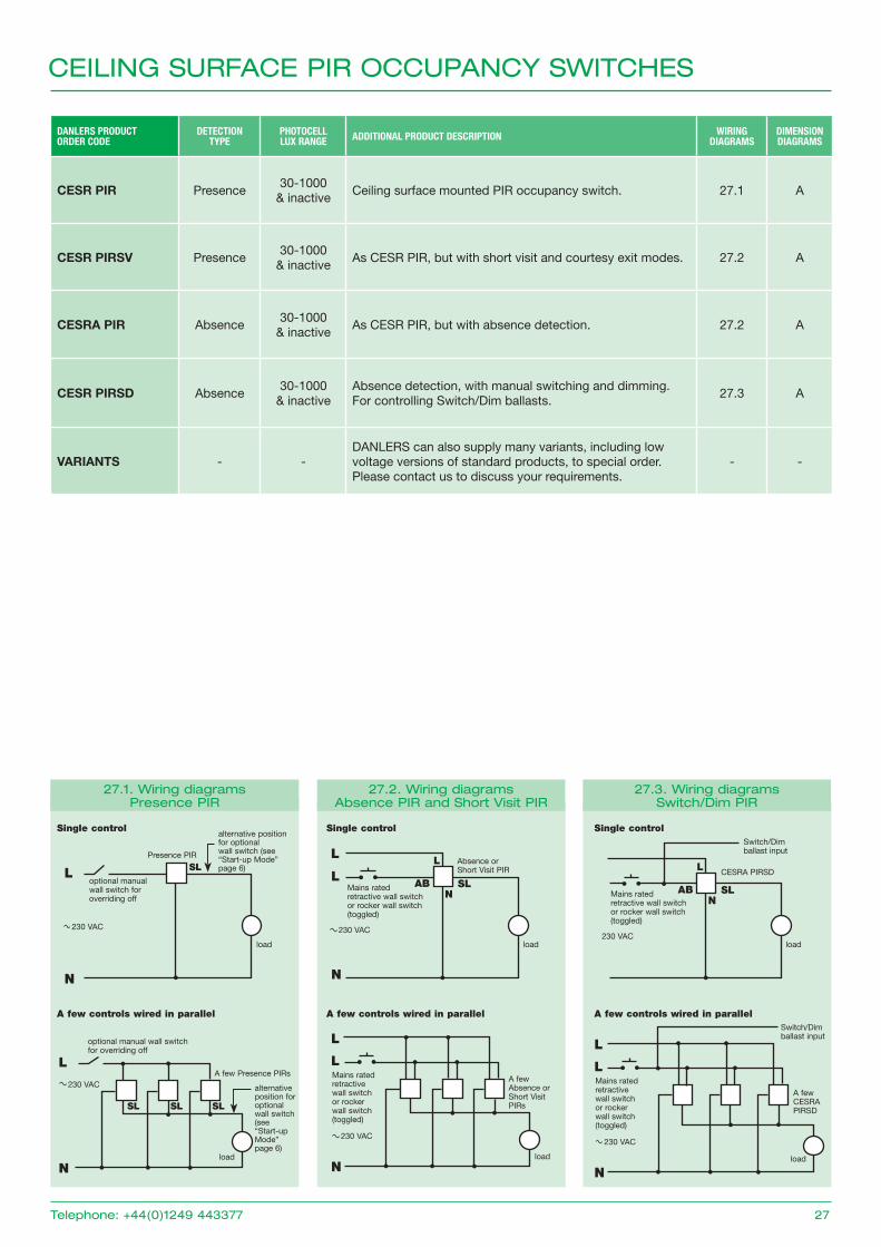
DANLERS PRODUCT ORDER CODE
DETECTION TYPE
PHOTOCELL LUX RANGE ADDITIONAL PRODUCT DESCRIPTION WIRING
DIAGRAMSDIMENSION DIAGRAMS
CESR PIR Presence30-1000
& inactiveCeiling surface mounted PIR occupancy switch. 27.1 A
CESR PIRSV Presence30-1000
& inactiveAs CESR PIR, but with short visit and courtesy exit modes. 27.2 A
CESRA PIR Absence30-1000
& inactiveAs CESR PIR, but with absence detection. 27.2 A
CESR PIRSD Absence30-1000
& inactiveAbsence detection, with manual switching and dimming. For controlling Switch/Dim ballasts.
27.3 A
VARIANTS - -DANLERS can also supply many variants, including low voltage versions of standard products, to special order. Please contact us to discuss your requirements.
- -
27.3. Wiring diagrams Switch/Dim PIR
Single control
load
CESRA PIRSD
230 VAC
L
AB SLN
Mains rated retractive wall switch or rocker wall switch (toggled)
Switch/Dim ballast input
L
Nload
A few CESRA PIRSD
230 VAC
A few controls wired in parallel
Mains rated retractive wall switch or rocker wall switch (toggled)
LSwitch/Dim ballast input
A few Absence or Short Visit PIRs
Absence or Short Visit PIR
CEILING SURFACE PIR OCCUPANCY SWITCHES WITH DIMMING
28 www.danlers.co.uk
Up to 5m
Up to 7m
Up to 5m
Up to 7m Up to 5m
Up to5m
In open plan areasFor best coverage the PIRs should be spaced every 5m in either directionPIR
Strong detection zone
Secondary detection zone
Strong detection zone e.g. person moving arm
Secondary detection zone e.g. person walking (less sensitive when walking straight towards PIR switch)
For optimum coverage recommended mounting height between 2.4 and 5m.
PIR Quad detector gives 124 detection areas within the zone.
Plan view of detection zone Several PIR occupancy switchesPerspective view of detection zone
Detection diagrams
A - Dimensions in mm
plan side
45
91
91
80.5
This range of energy saving products is designed for controlling DALI, DSI and 1-10V dimmable ballasts for lighting loads.
These products are hard wired and can be mounted directly onto solid ceilings or onto a range of different mounting boxes. They can switch on when area is occupied and maintain a chosen lux level in the area by dimming the lights in response to changes in the ambient daylight level. There is also an adjustable “Run-on” timer, which allows the light to be returned to a minimum background level following a period of occupancy. This can either be for a chosen time period, or as a permanent background light.
Product options include:
● Presence or absence detection versions for DALI ballasts
● Presence or absence detection versions for 1-10VDC ballasts
● Presence or absence detection versions for DSI ballasts.
SPECIFICATION
Detection zone: 360°
Max. detection area: 7m diameter at 2.4m mounting height
Max. mounting height: 5m
Photocell range: 30-1000 lux and inactive
Time lag range: 10 seconds to 40 minutes in 9 steps
Run-on time: 0, 1, 2, 5, 10, 15, 20, 30 mins and infinite (always ON at minimum)
Dimensions: 91mm diameter x 45mm
LOADING - DIMMING
‘DALIP’ range: INTERNAL DALI POWER SUPPLY: Suitable for up to 12 ballasts* at 2mA
‘DALI’ range: EXTERNAL DALI POWER SUPPLY: Suitable for up to 20 ballasts* at 2mA
1-10V range: Suitable for up to 20 ballasts* at 2mA
‘DSIP’ range: INTERNAL DALI POWER SUPPLY: Suitable for up to 12 ballasts* at 2mA
‘DSI’ range: EXTERNAL DALI POWER SUPPLY: Suitable for up to 20 ballasts* at 2mA
LOADING - SWITCHING
All products listed opposite have a relay capable of switching the following loads: 6 amps (1500W) of fl uorescent load. 2 amps (500W) of CFL, LED Drivers and LED lamps and fi ttings.
5 YEAR WARRANTY - MADE IN THE U.K.
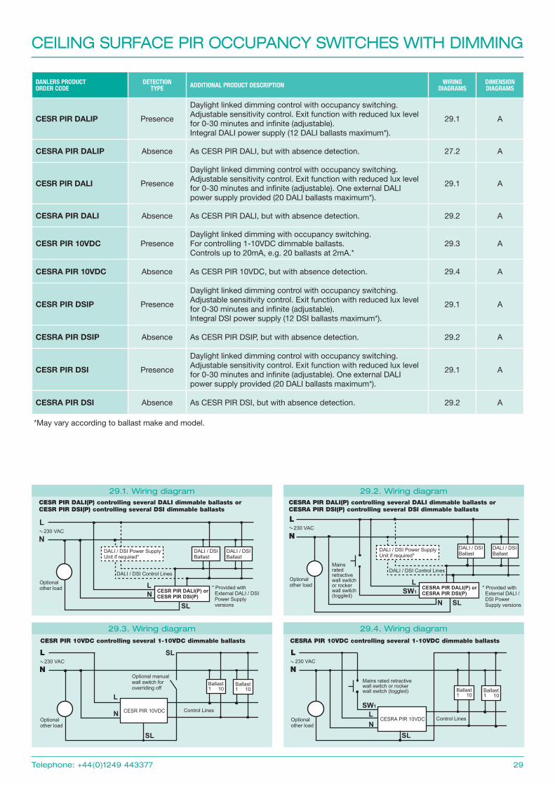
DANLERS PRODUCT ORDER CODE
DETECTION TYPE ADDITIONAL PRODUCT DESCRIPTION WIRING
DIAGRAMSDIMENSION DIAGRAMS
CESR PIR DALIP Presence
Daylight linked dimming control with occupancy switching. Adjustable sensitivity control. Exit function with reduced lux level for 0-30 minutes and infinite (adjustable). Integral DALI power supply (12 DALI ballasts maximum*).
29.1 A
CESRA PIR DALIP Absence As CESR PIR DALI, but with absence detection. 27.2 A
CESR PIR DALI Presence
Daylight linked dimming control with occupancy switching. Adjustable sensitivity control. Exit function with reduced lux level for 0-30 minutes and infinite (adjustable). One external DALI power supply provided (20 DALI ballasts maximum*).
29.1 A
CESRA PIR DALI Absence As CESR PIR DALI, but with absence detection. 29.2 A
CESR PIR 10VDC PresenceDaylight linked dimming with occupancy switching. For controlling 1-10VDC dimmable ballasts.Controls up to 20mA, e.g. 20 ballasts at 2mA.*
29.3 A
CESRA PIR 10VDC Absence As CESR PIR 10VDC, but with absence detection. 29.4 A
CESR PIR DSIP Presence
Daylight linked dimming control with occupancy switching. Adjustable sensitivity control. Exit function with reduced lux level for 0-30 minutes and infinite (adjustable). Integral DSI power supply (12 DSI ballasts maximum*).
29.1 A
CESRA PIR DSIP Absence As CESR PIR DSIP, but with absence detection. 29.2 A
CESR PIR DSI Presence
Daylight linked dimming control with occupancy switching. Adjustable sensitivity control. Exit function with reduced lux level for 0-30 minutes and infinite (adjustable). One external DALI power supply provided (20 DALI ballasts maximum*).
29.1 A
CESRA PIR DSI Absence As CESR PIR DSI, but with absence detection. 29.2 A
CEILING SURFACE PIR OCCUPANCY SWITCHES WITH DIMMING
Telephone: +44(0)1249 443377 29
29.1. Wiring diagramCESR PIR DALI(P) controlling several DALI dimmable ballasts or CESR PIR DSI(P) controlling several DSI dimmable ballasts
L
NDALI / DSI Power Supply Unit if required*
DALI / DSIBallast
CESR PIR DALI(P) orCESR PIR DSI(P)
DALI / DSI Control Lines
DALI / DSIBallast
* Provided with External DALI / DSI Power Supply versions
Optional other load
230 VAC
SL
LN
29.2. Wiring diagramCESRA PIR DALI(P) controlling several DALI dimmable ballasts or CESRA PIR DSI(P) controlling several DSI dimmable ballasts
L
NDALI / DSIBallast
CESRA PIR DALI(P) orCESRA PIR DSI(P)
DALI / DSI Control Lines
DALI / DSIBallast
Optional other load
230 VAC
SL
L
N
Mains ratedretractive wall switch or rocker wall switch (toggled)
SW1
DALI / DSI Power Supply Unit if required*
* Provided with External DALI / DSI Power Supply versions
CESR PIR 10VDC controlling several 1-10VDC dimmable ballasts
29.3. Wiring diagramCESRA PIR 10VDC controlling several 1-10VDC dimmable ballasts
29.4. Wiring diagram
L
N
Ballast1 10
CESR PIR 10VDC Control Lines
Optional other load
230 VAC
SL
L
N
Ballast1 10
SL
Optional manual wall switch for overriding off
L
N
Ballast1 10
CESRA PIR 10VDC Control LinesOptional other load
230 VAC
SL
LN
Ballast1 10
Mains rated retractive wall switch or rocker wall switch (toggled)
SW1
*May vary according to ballast make and model.
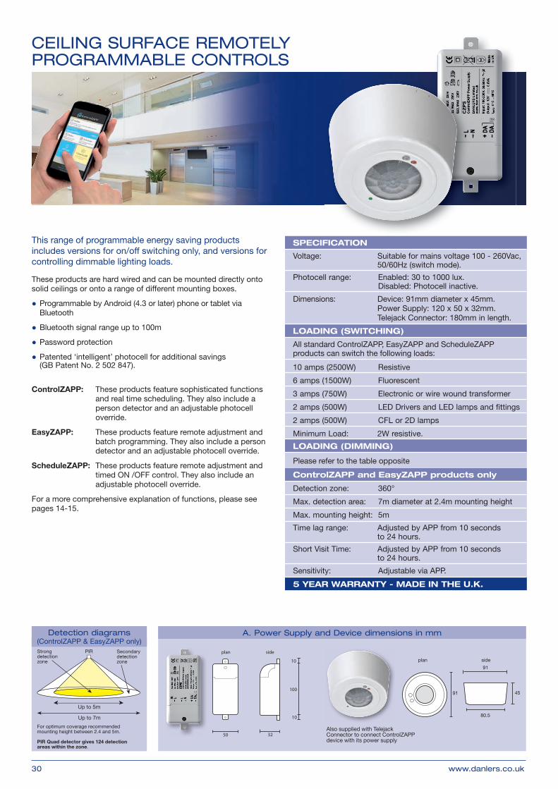
Up to 5m
Up to 7m
PIRStrong detection zone
Secondary detection zone
Strong detection zone i.e. person moving arm
Secondary detection zone i.e. person walking (less sensitive when walking straight towards PIR switch)
For optimum coverage recommended mounting height between 2.4 and 5m.
PIR Quad detector gives 124 detection areas within the zone.
Detection diagrams (ControlZAPP & EasyZAPP only)
CEILING SURFACE REMOTELY PROGRAMMABLE CONTROLS
30 www.danlers.co.uk
A. Power Supply and Device dimensions in mm
plan side
100
10
10
50 32Also supplied with Telejack Connector to connect ControlZAPP device with its power supply
This range of programmable energy saving products includes versions for on/off switching only, and versions for controlling dimmable lighting loads.
These products are hard wired and can be mounted directly onto solid ceilings or onto a range of different mounting boxes.
● Programmable by Android (4.3 or later) phone or tablet via Bluetooth
ControlZAPP: These products feature sophisticated functions and real time scheduling. They also include a person detector and an adjustable photocell override.
EasyZAPP: These products feature remote adjustment and batch programming. They also include a person detector and an adjustable photocell override.
ScheduleZAPP: These products feature remote adjustment and timed ON /OFF control. They also include an adjustable photocell override.
For a more comprehensive explanation of functions, please see pages 14-15.
plan side
45
91
91
80.5
SPECIFICATION
Voltage: Suitable for mains voltage 100 - 260Vac, 50/60Hz (switch mode).
Photocell range: Enabled: 30 to 1000 lux. Disabled: Photocell inactive.
Dimensions: Device: 91mm diameter x 45mm. Power Supply: 120 x 50 x 32mm. Telejack Connector: 180mm in length.
LOADING (SWITCHING)
All standard ControlZAPP, EasyZAPP and ScheduleZAPP products can switch the following loads:
10 amps (2500W) Resistive6 amps (1500W) Fluorescent 3 amps (750W) Electronic or wire wound transformer2 amps (500W) LED Drivers and LED lamps and fi ttings2 amps (500W) CFL or 2D lampsMinimum Load: 2W resistive.LOADING (DIMMING)
Please refer to the table opposite
ControlZAPP and EasyZAPP products only
Detection zone: 360°
Max. detection area: 7m diameter at 2.4m mounting height
Max. mounting height: 5m
Time lag range: Adjusted by APP from 10 seconds to 24 hours.
Short Visit Time: Adjusted by APP from 10 seconds to 24 hours.
Sensitivity: Adjustable via APP.
5 YEAR WARRANTY - MADE IN THE U.K.
DANLERS PRODUCT ORDER CODE LOADING INFORMATION AND ADDITIONAL PRODUCT DESCRIPTION SCHEDULING WIRING
CZCESR DALI Suitable for switching and dimming DALI ballasts (broadcast only). Can control up to 40mA, eg. 20 ballasts at 2mA (varies according to ballast type). ✓ 31.2 A
CZCESR 10VDCTotal load of ballast, lamps plus other load not more than 6 amps, including fluorescent. Can control up to 20mA, eg. 20 ballasts at 1mA. (varies according to ballast type).
EZCESR DALI Suitable for switching and dimming DALI ballasts (broadcast only). Can control up to 40mA, eg. 20 ballasts at 2mA (varies according to ballast type). ✗ 31.2 A
EZCESR 10VDCTotal load of ballast, lamps plus other load not more than 6 amps including fluorescent. Can control up to 20mA, eg. 20 ballasts at 1mA (varies according to ballast type).
✗ 31.3 A
SZCESRSwitching photocell - no person detection. 10 amp (2500W) Resistive. 6 amp (1500W) Fluorescent. 3 amp (750W) Transformer. 2 amp (500W) CFL, 2D, LED drivers & LED lamps.
✓ 31.1 A
VOLT FREE VARIANTS
Versions of the above ControlZAPP, EasyZAPP and ScheduleZAPP products are available with a volt free output, for switching a secondary signal rather than the supply voltage.
ControlZAPP and
ScheduleZAPP variants only
Not illustrated
A
ANCILLARY ITEMS
DBPSU DALI / DSI power supply unit for use with DANLERS DALI / DSI controls and third party DALI / DSI control solutions. Rated at 40mA.
Not applicable
31.2A
(Power supply)
WAOSW Wall override switch with AUTOMATIC / OFF control option and a temporary timed override ON switch (adjustable 1-120 minutes). For 230VAC supply only.