48
Cellular Design Concept & Fundamentals
| Date post: | 06-Apr-2018 |
| Category: |
Documents |
| Upload: | hazem-tarek-mahmoud |
| View: | 223 times |
| Download: | 0 times |
8/3/2019 Cellular Design Fundamentals
http://slidepdf.com/reader/full/cellular-design-fundamentals 1/48
Cellular Design
Concept & Fundamentals
8/3/2019 Cellular Design Fundamentals
http://slidepdf.com/reader/full/cellular-design-fundamentals 2/48
Design Objectives Large Coverage Area
Tall antenna/ high power
High Capacity
Frequency reuse
Old Systems: A single antenna had a capacity of
only 12 users in an area of 1000 sq. mi.!Design Goals: High capacity/large coverage
area at optimal radio spectrum efficiency
8/3/2019 Cellular Design Fundamentals
http://slidepdf.com/reader/full/cellular-design-fundamentals 3/48
Cellular Solution In the 1970s, Bell Labs developed a solution
(AMPS): Instead of using one large powerful
transmitter, lets use many small less powerfultransmitters
Advantages:
Very high capacity
Limited spectrum usage
Mobile sets can be manufactured with same setsof frequencies
8/3/2019 Cellular Design Fundamentals
http://slidepdf.com/reader/full/cellular-design-fundamentals 4/48
The Cellular Concept Divide coverage area into smaller
regions(cells of radius 2-50km) with one base
station at the center Divide spectrum into groups of non-
contiguous RF channels
Allocate one frequency group to each BS;nearby cells use a different group
If demand increases, increase no. of cells
8/3/2019 Cellular Design Fundamentals
http://slidepdf.com/reader/full/cellular-design-fundamentals 5/48
Some Design Parameters Cell size
Cell location RF channel allocation

8/3/2019 Cellular Design Fundamentals
http://slidepdf.com/reader/full/cellular-design-fundamentals 6/48
Why Hexagonal Cells? Radio coverage of a BS is modeled as a
hexagon because:
It permits easy analysis
It resembles a circle (no overlaps & gaps)
It requires the fewest cells to cover an
area (compared to other shapes) It approximates a circular radiation pattern
for an omni-directional antenna
8/3/2019 Cellular Design Fundamentals
http://slidepdf.com/reader/full/cellular-design-fundamentals 7/48
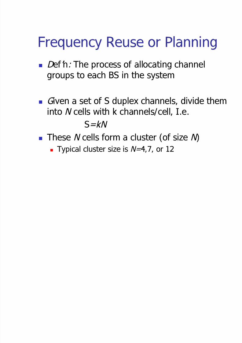
Frequency Reuse or Planning Defn: The process of allocating channel
groups to each BS in the system
Given a set of S duplex channels, divide theminto N cells with k channels/cell, I.e.
S=k N These N cells form a cluster (of size N)
Typical cluster size is N =4,7, or 12
8/3/2019 Cellular Design Fundamentals
http://slidepdf.com/reader/full/cellular-design-fundamentals 8/48
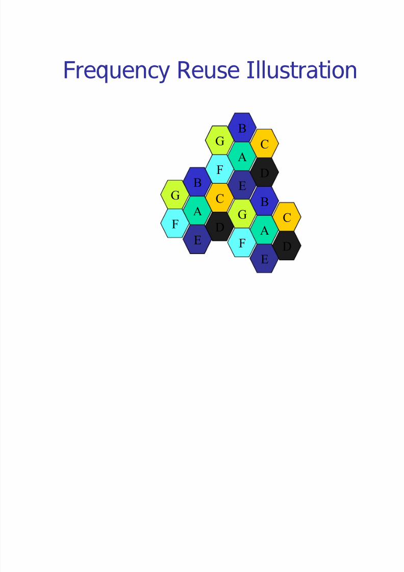
Frequency Reuse Illustration
A
C
D
B
G
F
E
A
C
D
B
G
F
E
A
C
D
B
G
F
E
8/3/2019 Cellular Design Fundamentals
http://slidepdf.com/reader/full/cellular-design-fundamentals 9/48
Cluster Size Tradeoff If a cluster is replicated M times, capacity is:
C=Mk N =MS If the cluster size (N) is reduced (while cell
size remains constant), more clusters will berequired; hence, capacity will increase; but
interference will also increase We want to minimize N such that a certainSIR ratio can be maintained
8/3/2019 Cellular Design Fundamentals
http://slidepdf.com/reader/full/cellular-design-fundamentals 10/48
Frequency Reuse Factor The Frequency Reuse factor of a
cellular system is defined as:
1/N
because each cell uses only 1/N th of the available channels

8/3/2019 Cellular Design Fundamentals
http://slidepdf.com/reader/full/cellular-design-fundamentals 11/48
Channel Assignment Fixed Assignment
Predetermined fixed set of channels are assignedto each cell
If all channels are busy,calls are blocked
Borrowing Strategy
Borrows a channel fromneighboring cells
MSC supervises theprocess
Dynamic Assignment MSC assigns a
channel to the BS asper some algorithm
Advantages: Increases capacity
Increases channel
utilization Disadvantages:
Increasedcomputational load
8/3/2019 Cellular Design Fundamentals
http://slidepdf.com/reader/full/cellular-design-fundamentals 12/48
Handoff Defn: The transfer of a call from one BS to
another while a MU moves in the area
It involves: Identification of a new BS
New voice and control channel assignment
It must be performed: successfully, infrequently and imperceptibly to the
user
8/3/2019 Cellular Design Fundamentals
http://slidepdf.com/reader/full/cellular-design-fundamentals 13/48
Handoff Threshold D efn: Optimal signal level at which to
initiate a handoff
Handoff Threshold (Pht )is usually set at avalue slightly higher than the minimumusable power level(Pmin) received at the BS
The margin, ( = Pht Pmin, is a system
parameter, which has to be set carefully If ( is too high, unnecessary handoffs occur
If ( is too low, the call will be lost becausethere will be insufficient time to complete
handoff
8/3/2019 Cellular Design Fundamentals
http://slidepdf.com/reader/full/cellular-design-fundamentals 14/48
Handoff deception Fading can result in the signal level
dropping below Pht
Running average signal level (over atime period) must be used to counterthis deception
Speed of MU alters running average Speed can be computed at BS from
signal statistics
8/3/2019 Cellular Design Fundamentals
http://slidepdf.com/reader/full/cellular-design-fundamentals 15/48
Dwell Time Defn: The time over which a call may be
maintained within a cell without handoff
Dwell time is determined by: Propagation
Interference
Distance
Time-varying effects (speed?) Dwell time statistics are needed to design
handoff algorithms
8/3/2019 Cellular Design Fundamentals
http://slidepdf.com/reader/full/cellular-design-fundamentals 16/48
1G Handoff Strategy RSSI( Received Signal Strength Indicator) of
all MUs is measured by the BS
A locator receiver (in each BS) is used tomeasure RSSI of MUs in neighboring cells
Based on this information, the MSC decides if
handoff is necessary or not Typical Handoff time is about 10 sec,
requiring ( to be about 6-12 dB
8/3/2019 Cellular Design Fundamentals
http://slidepdf.com/reader/full/cellular-design-fundamentals 17/48
2G Handoff Strategy MAHO (Mobile Assisted Handoff) used
Each MU measures the received power from
surrounding BS and continually reports theresults to BS
Handoff is initiated when Power receivedfrom neighboring BS is higher for a certain
period of time MAHO is much faster (about 1-2 sec); suited
for micro-cellular environments
8/3/2019 Cellular Design Fundamentals
http://slidepdf.com/reader/full/cellular-design-fundamentals 18/48
Soft Handoff Defn: The ability to select between
RSSI from various BS
In IS-95, CDMA spread spectrumsystems, MUs share the same channelin each cell. Hence, handoff does not
require new channel assignment MSC decides which version of the signal
to send to the PSTN
8/3/2019 Cellular Design Fundamentals
http://slidepdf.com/reader/full/cellular-design-fundamentals 19/48
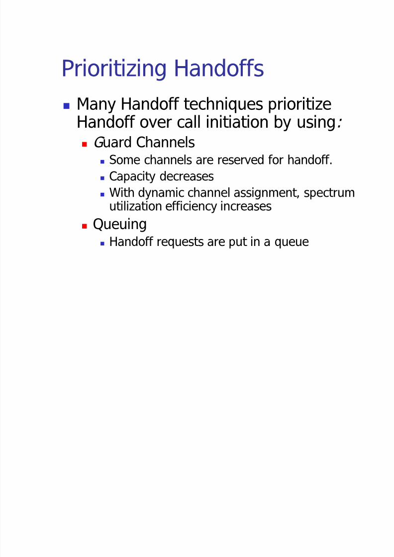
Prioritizing Handoffs Many Handoff techniques prioritize
Handoff over call initiation by using: Guard Channels
Some channels are reserved for handoff.
Capacity decreases
With dynamic channel assignment, spectrum
utilization efficiency increases Queuing
Handoff requests are put in a queue
8/3/2019 Cellular Design Fundamentals
http://slidepdf.com/reader/full/cellular-design-fundamentals 20/48
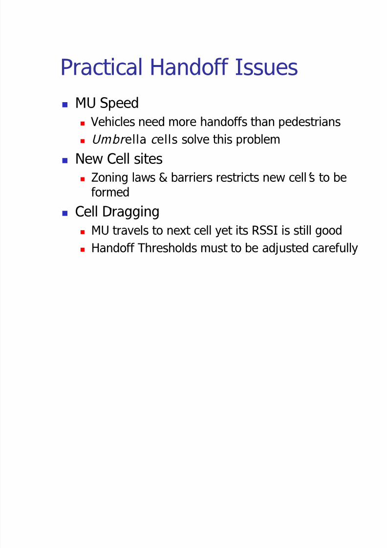
Practical Handoff Issues MU Speed
Vehicles need more handoffs than pedestrians
Umbr ella cells solve this problem
New Cell sites Zoning laws & barriers restricts new cells to be
formed
Cell Dragging
MU travels to next cell yet its RSSI is still good
Handoff Thresholds must to be adjusted carefully
8/3/2019 Cellular Design Fundamentals
http://slidepdf.com/reader/full/cellular-design-fundamentals 21/48
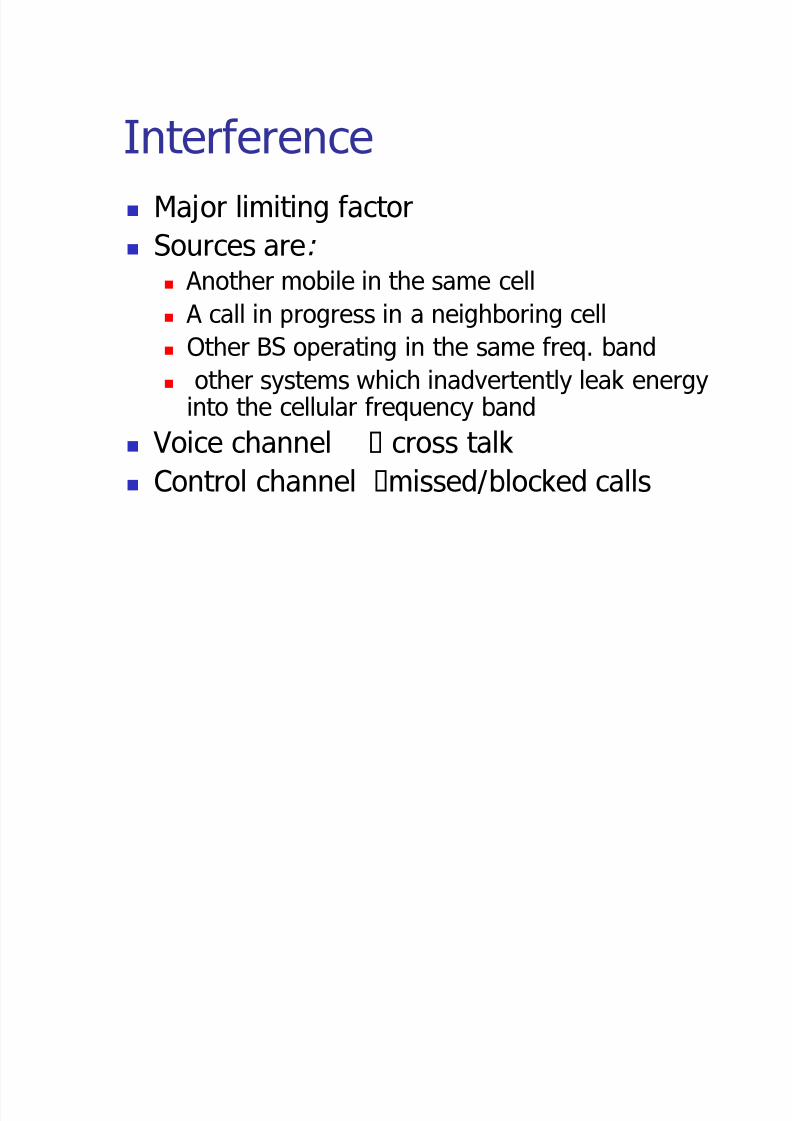
Interference Major limiting factor
Sources are: Another mobile in the same cell A call in progress in a neighboring cell
Other BS operating in the same freq. band
other systems which inadvertently leak energy
into the cellular frequency band Voice channel cross talk
Control channel missed/blocked calls
8/3/2019 Cellular Design Fundamentals
http://slidepdf.com/reader/full/cellular-design-fundamentals 22/48
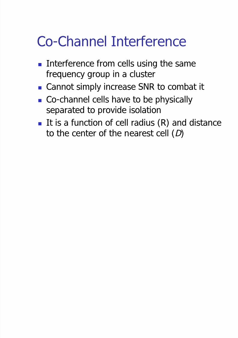
Co-Channel Interference Interference from cells using the same
frequency group in a cluster
Cannot simply increase SNR to combat it
Co-channel cells have to be physicallyseparated to provide isolation
It is a function of cell radius (R) and distanceto the center of the nearest cell (D)

8/3/2019 Cellular Design Fundamentals
http://slidepdf.com/reader/full/cellular-design-fundamentals 23/48
Co-Channel Reuse Ratio The Co-channel Reuse Ratio, Q, is defined as:
Increasing Q increases the spatial separationbetween co-channel cells; however, it alsoincrease N thereby decreasing capacity
Tradeoff must be made between Q and N
N R
DQ 3!!
8/3/2019 Cellular Design Fundamentals
http://slidepdf.com/reader/full/cellular-design-fundamentals 24/48
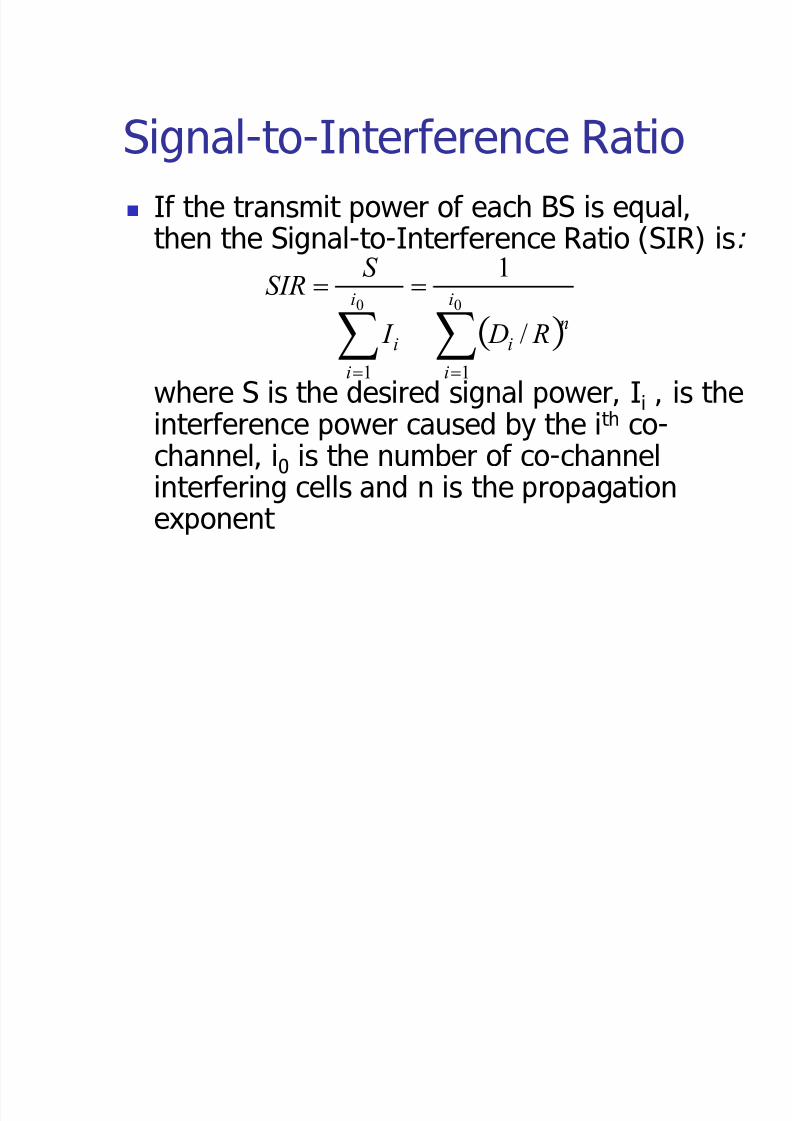
Signal-to-Interference Ratio If the transmit power of each BS is equal,
then the Signal-to-Interference Ratio (SIR) is:
where S is the desired signal power, Ii , is the
interference power caused by the ith co-channel, i0 is the number of co-channelinterfering cells and n is the propagationexponent
§§!!
!!00
11
/
1
i
i
n
i
i
i
iR D I
S SIR

8/3/2019 Cellular Design Fundamentals
http://slidepdf.com/reader/full/cellular-design-fundamentals 25/48
SIR Approximation If we consider only the first layer of
interfering cells, then the SIR will be:
Note that SIR E N!
For AMPS, Given SIR=18dB, then N =7
00
3/
i
N
i
R DSIR
nn
!!
8/3/2019 Cellular Design Fundamentals
http://slidepdf.com/reader/full/cellular-design-fundamentals 26/48
Adjacent Channel Interference Interference from signals adjacent in
frequency
It is caused by: Imperfect receiver filters
Near-far effect
High & low power transmitted in contiguouschannels
It can be minimized by careful filtering, use of guard bands and channel assignment
8/3/2019 Cellular Design Fundamentals
http://slidepdf.com/reader/full/cellular-design-fundamentals 27/48
Power Control Power level transmitted by MUs are
constantly controlled by BS s
PC ensures that each MU transmits at thesmallest power level necessary
This process reduces SIR, increases capacityand increases battery life
It is especially important in CDMA where allusers in the cell share one channel

8/3/2019 Cellular Design Fundamentals
http://slidepdf.com/reader/full/cellular-design-fundamentals 28/48
AMPS Channel Allocation 832(666+166) channels allocated by FCC
The forward channel (870.030MHz) and
reverse channel (825.030MHz) is numberedChannel 1
FCC licensed out the channels to twocompetitors and divided the channels into
Block A & Block B Out of the 416 channels, 395 are voice
channels and 21 are control

8/3/2019 Cellular Design Fundamentals
http://slidepdf.com/reader/full/cellular-design-fundamentals 29/48
AMPS (example 2.3) The 395 channels are divided into 21
groups of about 19 channels each
For N=7, each cell uses 3 groups orabout 57 channels (channels are at least 7 channels away from each other)
For example, one group will containchannels 1,8,15,22,29,309,670,1017(see table 2.2)
8/3/2019 Cellular Design Fundamentals
http://slidepdf.com/reader/full/cellular-design-fundamentals 30/48
Trunking Theory It allows a large number of users to
share the limited number of channels ina cell according to statistics
How many channels do I need toaccommodate x numbers of users?
Tradeoff b/w number of channels, C,and Outage percentage
8/3/2019 Cellular Design Fundamentals
http://slidepdf.com/reader/full/cellular-design-fundamentals 31/48
Grade of Service GOS is a measure of congestion in system,
I.e. it is the ability of a user to access a
trunked system during its busiest hour It is a benchmark
Design Issue: Given a GOS, estimate amaximum capacity level for a set of channelsin the wireless network
In AMPS, GOS is 2% blocking
8/3/2019 Cellular Design Fundamentals
http://slidepdf.com/reader/full/cellular-design-fundamentals 32/48
Traffic Intensity It is a measure of channel utilization time, or
the average channel occupancy
One Erlang represents the amount of TrafficIntensity carried by a channel that iscompletely occupied
The Traffic Intensity per user is:
Au=µH where µ is the average number of callrequests per unit time and H is the averagecall duration
8/3/2019 Cellular Design Fundamentals
http://slidepdf.com/reader/full/cellular-design-fundamentals 33/48
Total Offered Traffic Intensity If the system has U users, then the
total offered traffic Intensity is:
A= UAu
If the total Traffic is distributed evenlyamongst C Channels, then the totalTraffic Intensity per channel is:
A= Uau /C
8/3/2019 Cellular Design Fundamentals
http://slidepdf.com/reader/full/cellular-design-fundamentals 34/48
Blocked Calls Cleared This trunked system offers no queuing for call
requests
User is given access to a channel on demandand blocked if no channel is available
Assumptions are: Poisson call arrivals/exponential channel
occupation
Infinite number of users/finite number of channels

8/3/2019 Cellular Design Fundamentals
http://slidepdf.com/reader/full/cellular-design-fundamentals 35/48
Erlang B Formula Blocked Calls Cleared truncked system aka
M/M/m queue and leads to the Erlang B
formula It determines blocking probability and is a
measure of the GOS
It provides a conservative estimate of GOS
because in actual life there are finite numberof users
See Fig. 2.6 page 49 of text
8/3/2019 Cellular Design Fundamentals
http://slidepdf.com/reader/full/cellular-design-fundamentals 36/48
Capacity At any given time, capacity of a system
is limited to the number of channels, C.
Using Trunking/Queuing theory,Capacity can be increased
Capacity increases with C and with GOS
(outage percentage)
8/3/2019 Cellular Design Fundamentals
http://slidepdf.com/reader/full/cellular-design-fundamentals 37/48
Blocked Calls Delayed This trunked system provides a queue
to hold calls which are blocked
Call requests are delayed until achannel is available
GOS is the Probability that a call is
blocked after waiting t sec in a queue
8/3/2019 Cellular Design Fundamentals
http://slidepdf.com/reader/full/cellular-design-fundamentals 38/48
Erlang C Formula It is the probability that a call is initially
denied access? I.e. Pr[delay>0].
It is a function of the Traffic Intensity, A, and the number of channels, C.
See Fig. 2.7 on page 50.
8/3/2019 Cellular Design Fundamentals
http://slidepdf.com/reader/full/cellular-design-fundamentals 39/48
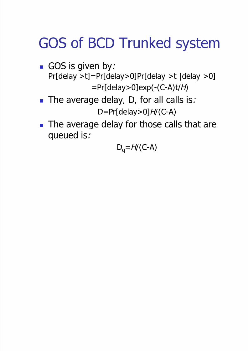
GOS of BCD Trunked system GOS is given by:
Pr[delay >t]=Pr[delay>0]Pr[delay >t |delay >0]
=Pr[delay>0]exp(-(C-A)t/H ) The average delay, D, for all calls is:
D=Pr[delay>0]H /(C-A)
The average delay for those calls that arequeued is:
Dq=H /(C-A)

8/3/2019 Cellular Design Fundamentals
http://slidepdf.com/reader/full/cellular-design-fundamentals 40/48
Trunking Efficiency It is a measure of the number of users which
can be offered a particular GOS using fixed
number of channels 10 channel trunked system has higher
Trunking efficiency than two 5 channeltrunked systems because it can support 60%
more traffic [See table 2.4 on pg. 47]
Be careful when you allocate channels!
8/3/2019 Cellular Design Fundamentals
http://slidepdf.com/reader/full/cellular-design-fundamentals 41/48
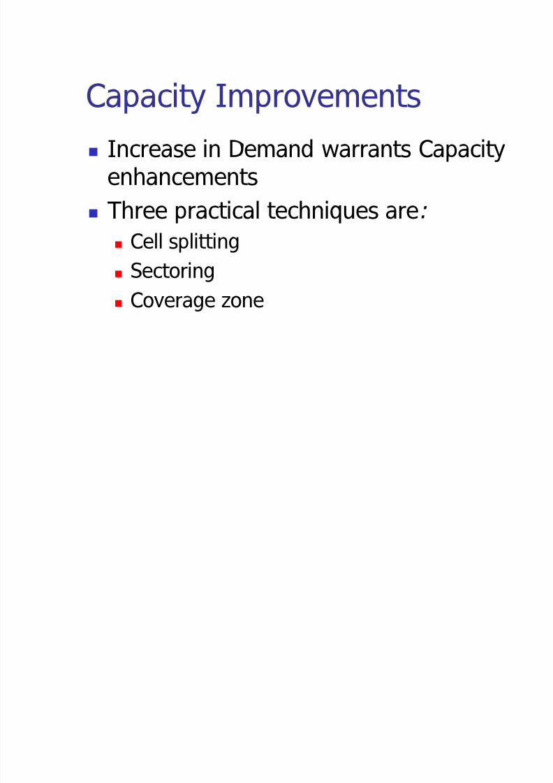
Capacity Improvements Increase in Demand warrants Capacity
enhancements
Three practical techniques are:
Cell splitting
Sectoring
Coverage zone

8/3/2019 Cellular Design Fundamentals
http://slidepdf.com/reader/full/cellular-design-fundamentals 42/48
Cell Splitting It is the process of subdividing a congested
cell into smaller cells
Capacity increased because freq. re-useincreased. I.e. no. of channels increased
Channel allocation scheme remains intact
Antenna Power and height are subsequently
reduced If microcells have half the radius, and with
n=4, trasmit power must be reduced by 1/16or 12 dB for the same SIR

8/3/2019 Cellular Design Fundamentals
http://slidepdf.com/reader/full/cellular-design-fundamentals 43/48
Cell Splitting 2 In practice, not all cells are split at the
same time. I.e. different cell sizes exist
simultaneously In such cases, channels in the old cell
must be broken into two channelgroups
Antenna downtilting is used to limit thecoverage of microcells
8/3/2019 Cellular Design Fundamentals
http://slidepdf.com/reader/full/cellular-design-fundamentals 44/48
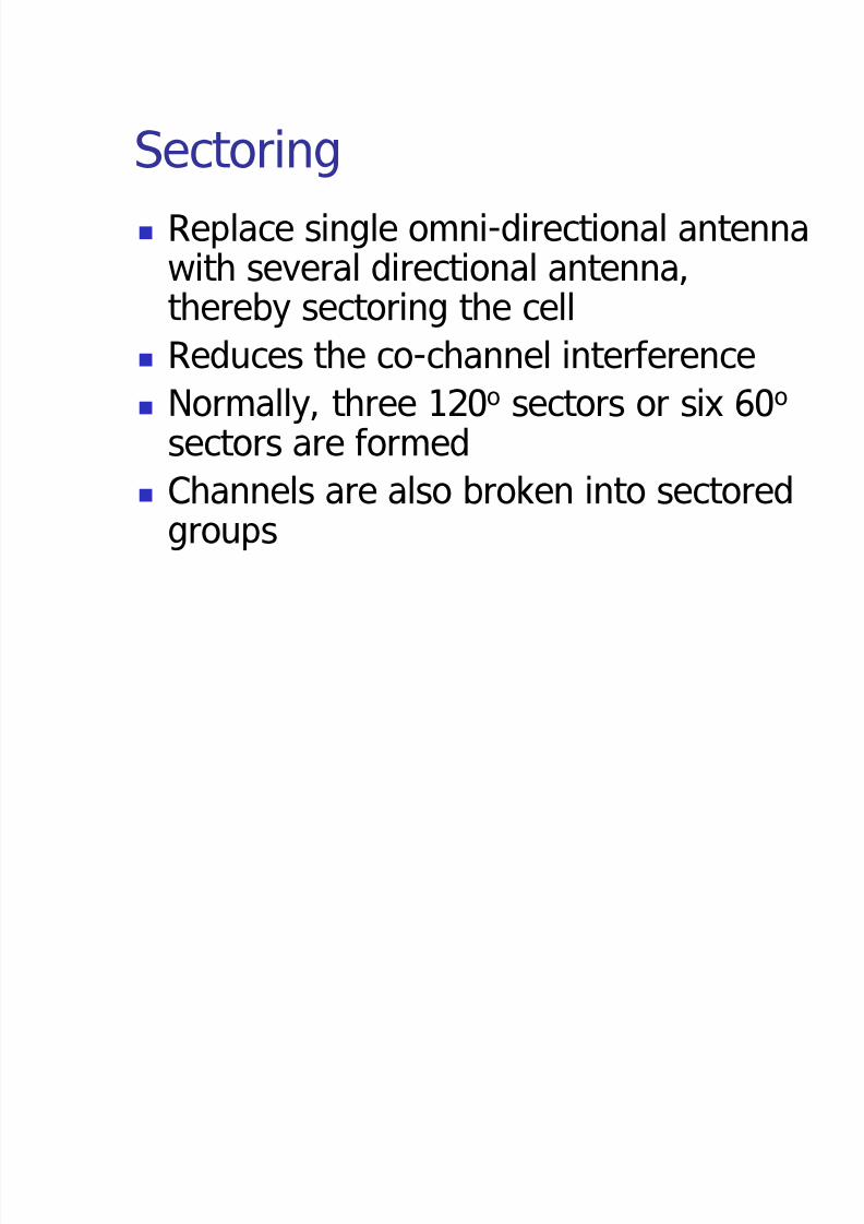
Sectoring Replace single omni-directional antenna
with several directional antenna,
thereby sectoring the cell Reduces the co-channel interference
Normally, three 120o sectors or six 60o
sectors are formed Channels are also broken into sectored
groups
8/3/2019 Cellular Design Fundamentals
http://slidepdf.com/reader/full/cellular-design-fundamentals 45/48
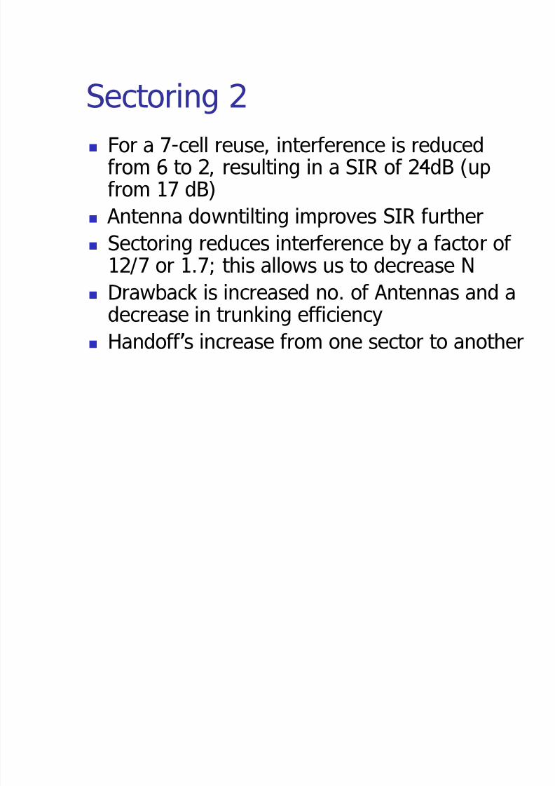
Sectoring 2 For a 7-cell reuse, interference is reduced
from 6 to 2, resulting in a SIR of 24dB (up
from 17 dB) Antenna downtilting improves SIR further
Sectoring reduces interference by a factor of 12/7 or 1.7; this allows us to decrease N
Drawback is increased no. of Antennas and adecrease in trunking efficiency
Handoff s increase from one sector to another
8/3/2019 Cellular Design Fundamentals
http://slidepdf.com/reader/full/cellular-design-fundamentals 46/48
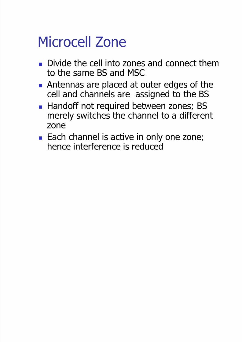
Microcell Zone Divide the cell into zones and connect them
to the same BS and MSC
Antennas are placed at outer edges of thecell and channels are assigned to the BS
Handoff not required between zones; BS merely switches the channel to a different
zone Each channel is active in only one zone;
hence interference is reduced

8/3/2019 Cellular Design Fundamentals
http://slidepdf.com/reader/full/cellular-design-fundamentals 47/48
Microcell Zone 2 Especially useful along highways
Co-channel interference is reduced Capacity is increased yet trunking
efficiency is not degraded
Capacity is increased by a factor of 7/3or 2.33 over a conventional 7-cell omnisystem
8/3/2019 Cellular Design Fundamentals
http://slidepdf.com/reader/full/cellular-design-fundamentals 48/48
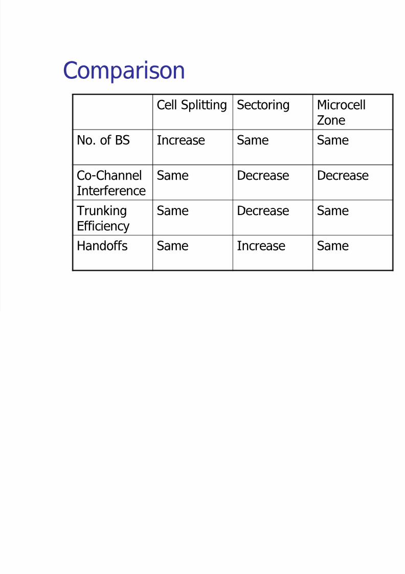
ComparisonCell Splitting Sectoring Microcell
Zone
No. of BS Increase Same Same
Co-ChannelInterference
Same Decrease Decrease
TrunkingEfficiency Same Decrease Same
Handoffs Same Increase Same


