© 2018 Perspecta Labs
Cellular Range Telemetry Network: Field Test Results Overview
Eric Beck, Shobha Erramilli, William Johnson, Achilles Kogiantis, Jenny Maung, Kiran Rege, Anthony Triolo and Jeff YoungMay 15, 2019
[DISTRIBUTION STATEMENT A. Approved for public release; Distribution is unlimited 412TW-PA-19249]
Addressing high Doppler shifts in Aeronautical Mobile Telemetry (AMT)– the Perspecta Labs solution
2
The LTE UE-appliquécombination has been tested extensively in the lab.
LTE UE Augmented with Appliqué
The field test setup – ground test
3
eNB 1 eNB 2
Drive Test Area
Car with an appliqué-LTE terminal combination and a separate GPS device
(UE Augmented with Appliqué)
4
CeRTN 4G LTE base station site installationeNB1 eNB1 eNB2
Parameter Value
Operating Frequency
Lower C4.4-5.0GHz
Bandwidth 20MHz
Duplexing Mode
TDD
eNB Antennas 4Rx, 2Tx
Patch Antennas
Broad Beam-width
Test Article Antennas
2Rx, 1Tx
Applique Doppler shift tracking
5
• Tracking during Handover events• Computed Doppler generated from GPS readings of the TA• Measured Doppler estimated and applied at the applique
-300
-250
-200
-150
-100
12:28:48 12:43:12 12:57:36 13:12:00 13:26:24 13:40:48 13:55:12 14:09:36 14:24:00
-1100
-600
-100
400
900
1400
1900
RS
RP
(d
b)
Do
pp
ler
(Hz)
Day 3 Track1 - Measured and Computed Doppler
Measured Doppler eNB1 Computed Doppler eNB2 Computed Doppler eNb1 RSRP eNB2 RSRP
Measured and Computed Doppler
Measured DopplereNB1 Computed DopplereNB2 Computed Doppler
Laboratory flight path emulation
8
• Reproduce an accurate emulation of an actual flight plan in the lab: • Two eNBs, one TA: Doppler, Gain, and Distance from eNB calculated from flight plan and
played back in real time
• Straight Flight East to WestFlight plan emulation in lab: ICNC output
eNB 1eNB 2
EPC ICNCIperf
Flight Path
Conclusion
10
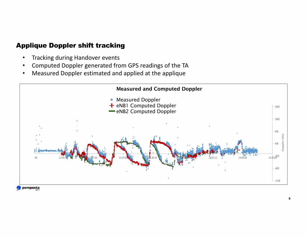
• Throughout the field test (as well as the lab tests), the appliqué was able to accurately estimate and compensate for the Doppler shift associated with the serving eNB and helped maintain the LTE link.
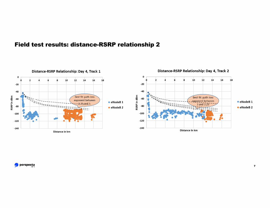
• Propagation analysis complicated by several factors: • Presence of shadowing• lack of a large number of independent measurements.
• Some conclusions can still be drawn from the available data:• Fitting a power-law curve to the highest observed RSRP levels in the distance-RSRP graphs yielded
values of path-loss exponent that vary between 2.00 and 3.25.• These measurements lead us to believe that for an airborne TA, the path-loss exponent is likely to
be close to its free-space value of 2. (Higher received power levels at similar distances.)• Often, (per-UE) throughput levels between 25 and 30 Mbps were reached even at a distance of
16 km. Using this observation in conjunction with the previous one, one can reasonably expect an airborne TA to attain similar throughputs at significantly larger distances.