24
Surgical Technique *smith&nephew SLR-PLUS™ Cementless Revision Stem
Surgical Technique *smith&nephewSLR-PLUS™ Cementless Revision Stem


SLR-PLUS™
Table of Contents
Comments from the Author’s Clinic ...................................... 3Indications ............................................................................ 4Contraindications .................................................................. 5Preoperative Planning ........................................................... 5Surgical Technique ................................................................ 6Postoperative Treatment .......................................................11Explantation of the SLR-PLUS Revision Stem ........................ 12Implants ............................................................................... 14Instruments .......................................................................... 16Sterilization ......................................................................... 20
Nota Bene
The technique description herein is made available to the healthcare professional to illustrate the authors’ suggested treatment for the uncomplicated procedure. In the fi nal analysis, the preferred treatment is that which addresses the needs of the patient.
1

2
Orthopaedic Hospital Gersthof, Wielemansgasse 28, 1180 Vienna, Austria
Cementless systems have been successfully used for many decades for primary hip re-placement. This preference is also evident in the use of cementless implants in revision surgery to replace loosened implants, although in the past negative trade-offs often had to be accepted. The cementless revision devic-es previously available were suitable only for very straightforward or for very complex cas-es. Now, however, there is a system to suit the middle range of hip revision arthroplasty, and thus for the vast majority of cases: the SLR-PLUS™ Revision Stem can be used to manage up to 80% of all revision cases according our experience.
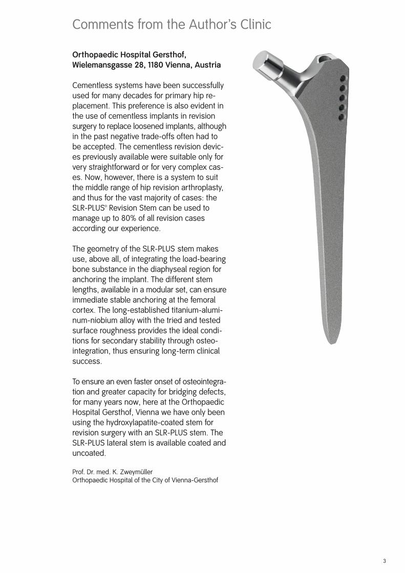
The geometry of the SLR-PLUS stem makes use, above all, of integrating the load-bearing bone substance in the diaphyseal region for anchoring the implant. The different stem lengths, available in a modular set, can ensure immediate stable anchoring at the femoral cortex. The long-established titanium-alumi-num-niobium alloy with the tried and tested surface roughness provides the ideal condi-tions for secondary stability through osteo-integration, thus ensuring long-term clinical success.
To ensure an even faster onset of osteointegra-tion and greater capacity for bridging defects, for many years now, here at the Orthopaedic Hospital Gersthof, Vienna we have only been using the hydroxylapatite-coated stem for revision surgery with an SLR-PLUS stem. The SLR-PLUS lateral stem is available coated and uncoated.
Prof. Dr. med. K. ZweymüllerOrthopaedic Hospital of the City of Vienna-Gersthof
Comments from the Author’s Clinic
3
4
The SLR-PLUS™ revision stem is designed for prosthetic arthroplasty in revision surgery.
The main indication for this stem is revision of a loose cemented implant. In this condition, the femur will frequently be found to be damaged all along the cement mantle, and the re-maining cortex will be very thin. In such cases, the aim should be to obtain distal implant fi xation, and to preserve the thinned proximal bone stock.
In the past decade, experience with non-cemented revision arthroplasty suggests that, wherever possible, a non-cemented device should be used: non-cemented replacement obviates the problems of methyl methacrylate toxicity and of foreign body granuloma forma-tion. The implant will be fi rmly seated, allowing the host bone to recover and regenerate rapidly, to augment the periprosthetic bone stock.
A second indication for this stem is revision of loose cementless implants of whatever pattern and conditions following infections where a temporary girdlestone situation has arisen. Posttraumatic conditions with or without bone defects can also be treated with the SLR-PLUS stem.
Thus, the following main indications are:
loosened cemented hip endoprosthesesloosened cementless hip endoprosthesesre-implantation following infectionposttraumatic conditions
Indications for the SLR-PLUS lateral stem
The SLR-PLUS lateral stem has been designed to optimise the lateralisation of the femur (offset) in revision surgery. Lateralisation also increases soft tissue tension, which has the advantage of preventing luxation of the head out of the cup. Sometimes the use of a SLR-PLUS lateral stem may require the use of a shorter neck than would be used with the standard stem. This helps to avoid an undesirable lengthening of the leg.
The use of the SLR-PLUS lateral stem is thus indicated in the following situations:
to prevent an undesirable medialisation of the femoral stemin the case of insuffi cient soft tissue tensionto reduce the risk of postoperative luxationto compensate for differences in leg length
Indications for the SLR-PLUS™ standard stem
• • ••
• • • •

5
Contraindications for the SLR-PLUS™ standard and SLR-PLUS lateral stem
The main indication for the SLR-PLUS revision stem only excludes severe revision cases, where the implant cannot be stabilized as a result of extensive bone rarefaction far into the diaphyseal region. These cases can be treated with the MODULAR-PLUS™ revision stem system, which is also anchored in the distal half of the femur.
The use of the SLR-PLUS stem is contraindicated in the following situations:
extensive bone defects extending far distal to the lesser trochanter and thereby reducing the stable anchoring of the SLR-PLUS revision stem to less than halfbone defects following tumour resections
Preoperative Planning
The planning of the correct prosthesis size and of the appropriate offset, as well as the neck length are preoperatively established using ap and axial x-ray templates. Preoperative plan-ning should always be carried out for orientation. X-ray templates for the SLR-PLUS standard and the SLR-PLUS lateral revision stem are available with a 15% magnifi cation.
It should be noted, however, that X-Ray templates are not as reliable for determining implant sizing in revision cases as they are in planning for primary implantations and can therefore only provide an approximate estimate of the actual stem size required.
•
•
6
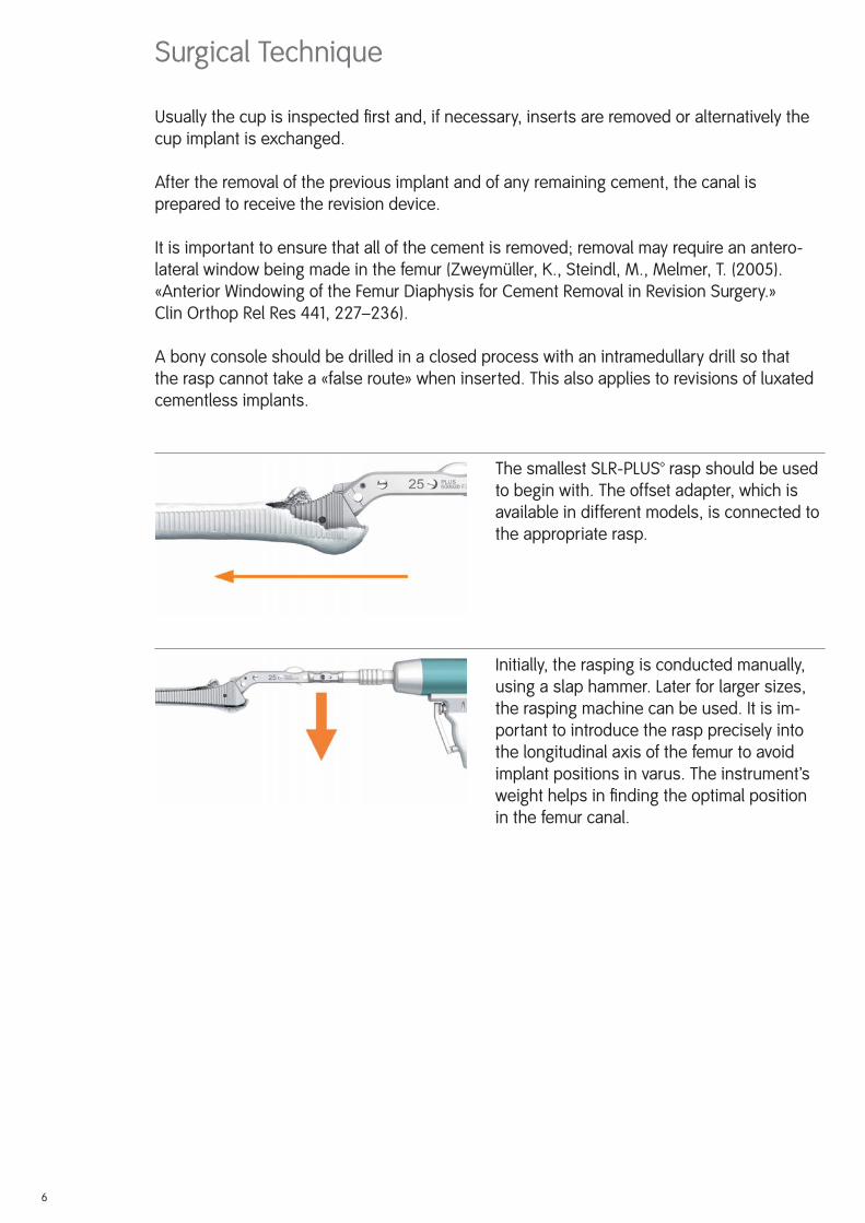
The smallest SLR-PLUS™ rasp should be used to begin with. The offset adapter, which is available in different models, is connected to the appropriate rasp.
Initially, the rasping is conducted manually, using a slap hammer. Later for larger sizes, the rasping machine can be used. It is im-portant to introduce the rasp precisely into the longitudinal axis of the femur to avoid implant positions in varus. The instrument’s weight helps in fi nding the optimal position in the femur canal.
Surgical Technique
Usually the cup is inspected fi rst and, if necessary, inserts are removed or alternatively the cup implant is exchanged.
After the removal of the previous implant and of any remaining cement, the canal is prepared to receive the revision device.
It is important to ensure that all of the cement is removed; removal may require an antero-lateral window being made in the femur (Zweymüller, K., Steindl, M., Melmer, T. (2005). «Anterior Windowing of the Femur Diaphysis for Cement Removal in Revision Surgery.» Clin Orthop Rel Res 441, 227–236).
A bony console should be drilled in a closed process with an intramedullary drill so that the rasp cannot take a «false route» when inserted. This also applies to revisions of luxated cementless implants.
Montage des Fräsers
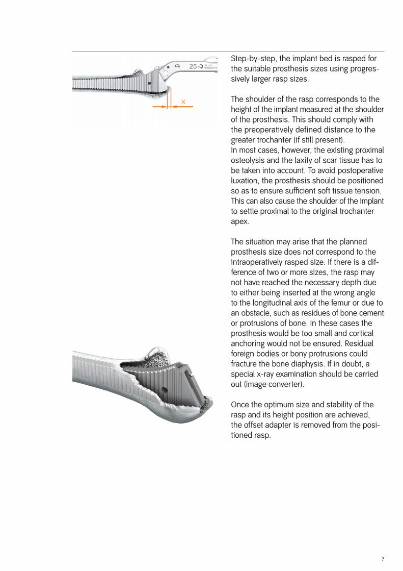
Step-by-step, the implant bed is rasped for the suitable prosthesis sizes using progres-sively larger rasp sizes.
The shoulder of the rasp corresponds to the height of the implant measured at the shoulder of the prosthesis. This should comply with the preoperatively defined distance to the greater trochanter (if still present).In most cases, however, the existing proximal osteolysis and the laxity of scar tissue has to be taken into account. To avoid postoperative luxation, the prosthesis should be positioned so as to ensure suffi cient soft tissue tension. This can also cause the shoulder of the implant to settle proximal to the original trochanter apex.
The situation may arise that the planned prosthesis size does not correspond to the intraoperatively rasped size. If there is a dif-ference of two or more sizes, the rasp may not have reached the necessary depth due to either being inserted at the wrong angle to the longitudinal axis of the femur or due to an obstacle, such as residues of bone cement or protrusions of bone. In these cases the prosthesis would be too small and cortical anchoring would not be ensured. Residual foreign bodies or bony protrusions could fracture the bone diaphysis. If in doubt, a special x-ray examination should be carried out (image converter).
Once the optimum size and stability of the rasp and its height position are achieved, the offset adapter is removed from the posi-tioned rasp.
7
x
8
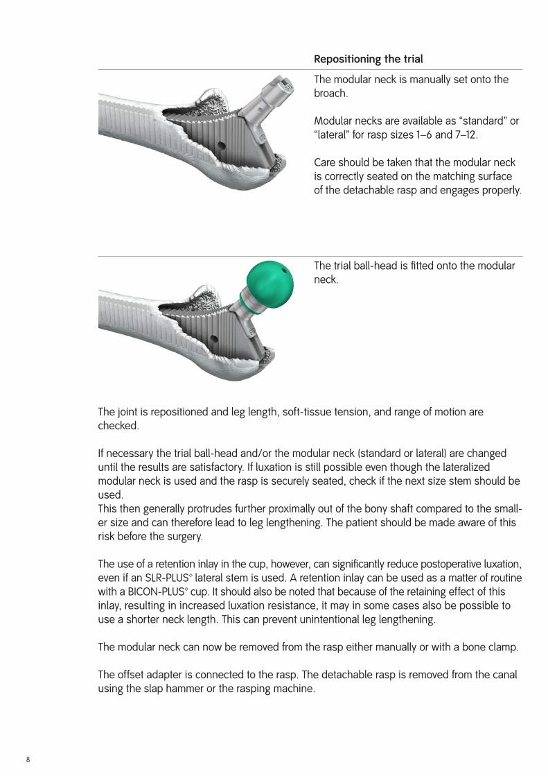
Repositioning the trial
The modular neck is manually set onto the broach.
Modular necks are available as “standard” or “lateral” for rasp sizes 1–6 and 7–12.
Care should be taken that the modular neck is correctly seated on the matching surface of the detachable rasp and engages properly.
The trial ball-head is fi tted onto the modular neck.
The joint is repositioned and leg length, soft-tissue tension, and range of motion are checked.
If necessary the trial ball-head and/or the modular neck (standard or lateral) are changed until the results are satisfactory. If luxation is still possible even though the lateralized modular neck is used and the rasp is securely seated, check if the next size stem should be used.This then generally protrudes further proximally out of the bony shaft compared to the small-er size and can therefore lead to leg lengthening. The patient should be made aware of this risk before the surgery.
The use of a retention inlay in the cup, however, can signifi cantly reduce postoperative luxation, even if an SLR-PLUS™ lateral stem is used. A retention inlay can be used as a matter of routine with a BICON-PLUS™ cup. It should also be noted that because of the retaining effect of this inlay, resulting in increased luxation resistance, it may in some cases also be possible to use a shorter neck length. This can prevent unintentional leg lengthening.
The modular neck can now be removed from the rasp either manually or with a bone clamp.
The offset adapter is connected to the rasp. The detachable rasp is removed from the canal using the slap hammer or the rasping machine.
9
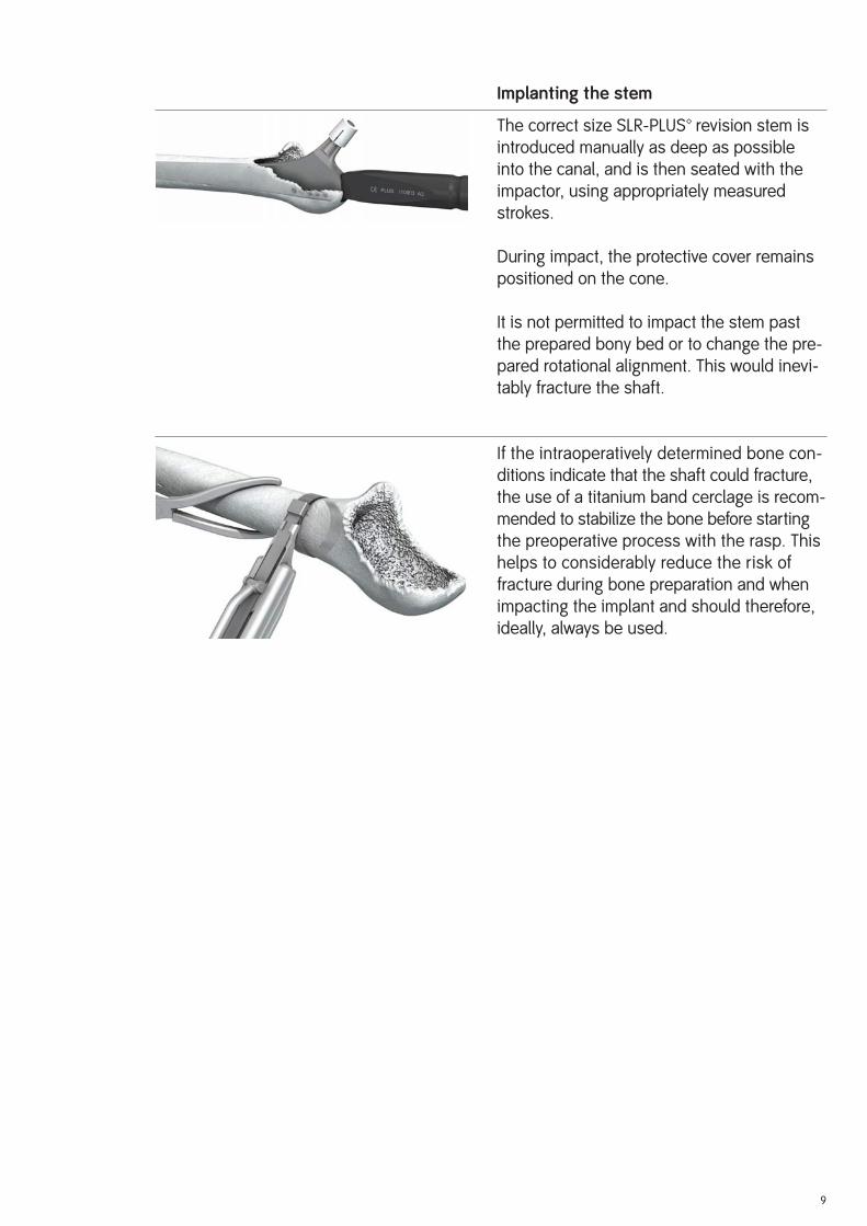
Implanting the stem
The correct size SLR-PLUS™ revision stem is introduced manually as deep as possible into the canal, and is then seated with the impactor, using appropriately measured strokes.
During impact, the protective cover remains positioned on the cone.
It is not permitted to impact the stem past the prepared bony bed or to change the pre-pared rotational alignment. This would inevi-tably fracture the shaft.
If the intraoperatively determined bone con-ditions indicate that the shaft could fracture, the use of a titanium band cerclage is recom-mended to stabilize the bone before starting the preoperative process with the rasp. This helps to considerably reduce the risk of fracture during bone preparation and when impacting the implant and should therefore, ideally, always be used.
10
The trial ball-head is then fi tted to the cone and a trial reposition is carried out. It is rec-ommended that the trial inlay be left for trial repositioning in the cup, because it cannot be determined until this stage if the standard in-lay can be used or if another inlay, such as a retention inlay, has to be used. If conditions are stable, especially when checking the movement of the hip, the defi nitive inlay is fi tted into the cup shell. Only then is the de-fi nitive ball-head fi tted.
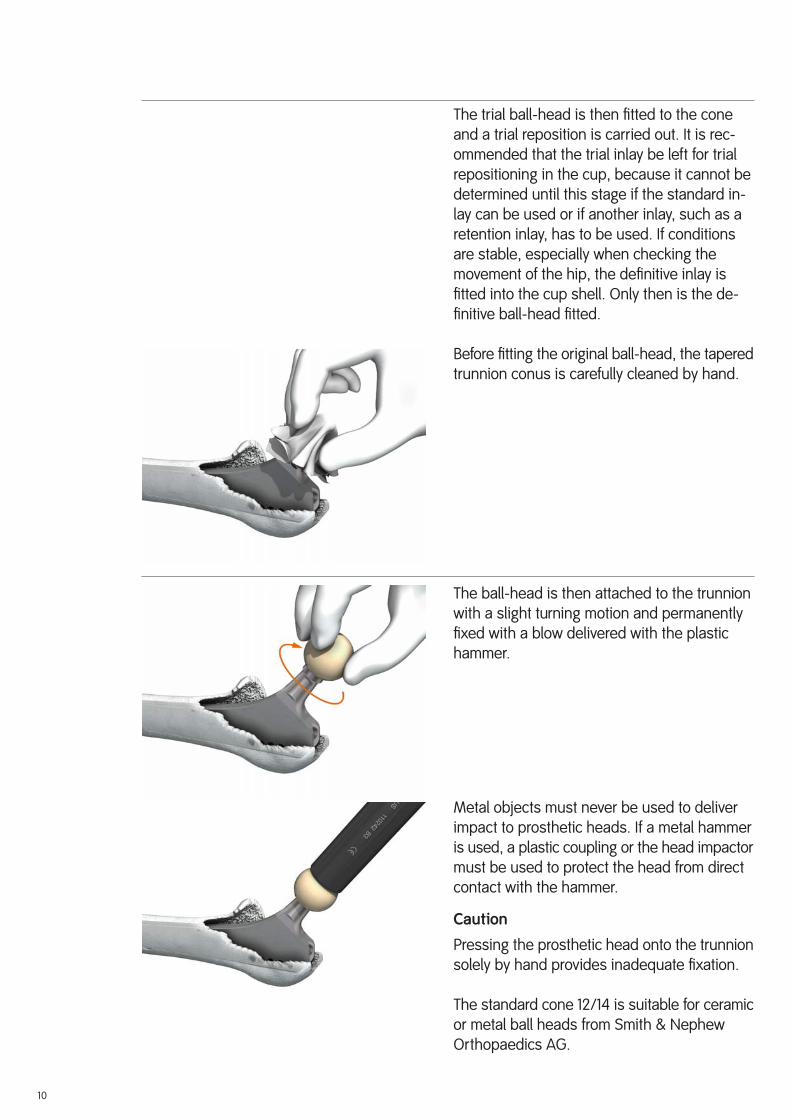
Before fi tting the original ball-head, the tapered trunnion conus is carefully cleaned by hand.
The ball-head is then attached to the trunnion with a slight turning motion and permanently fi xed with a blow delivered with the plastic hammer.
Metal objects must never be used to deliver impact to prosthetic heads. If a metal hammer is used, a plastic coupling or the head impactor must be used to protect the head from direct contact with the hammer.
Caution
Pressing the prosthetic head onto the trunnion solely by hand provides inadequate fi xation.
The standard cone 12/14 is suitable for ceramic or metal ball heads from Smith & Nephew Orthopaedics AG.

11
Reposition and wound suture
The defi nitive repositioning of the head in the cup then follows. If a retention inlay is used, the repositioning process of the ball should be followed as described in the surgical technique of the BICON-PLUS™ cup
Postoperative Treatment
Postoperative treatment should be provided according to the standards in the particular clinic. It should, however, be noted that revision surgery requires individual postoperative treatment, depending on the degree of preoperative bone destruction and the intraopera-tively achieved stability of the implant. In some cases the operated hip can be mobilized immediately and be partially load bearing, although mobilization without full load bearing is indicated for some time. During physiotherapy there is also the risk of postoperative luxation of the head out of the cup to be considered, as the stability can be considerably affected by soft tissue defects due to previous surgery.
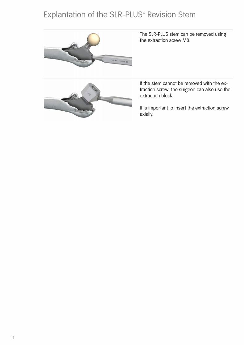
Explantation of the SLR-PLUS™ Revision Stem
The SLR-PLUS stem can be removed using the extraction screw M8.
If the stem cannot be removed with the ex-traction screw, the surgeon can also use the extraction block.
It is important to insert the extraction screw axially.
12

13
L
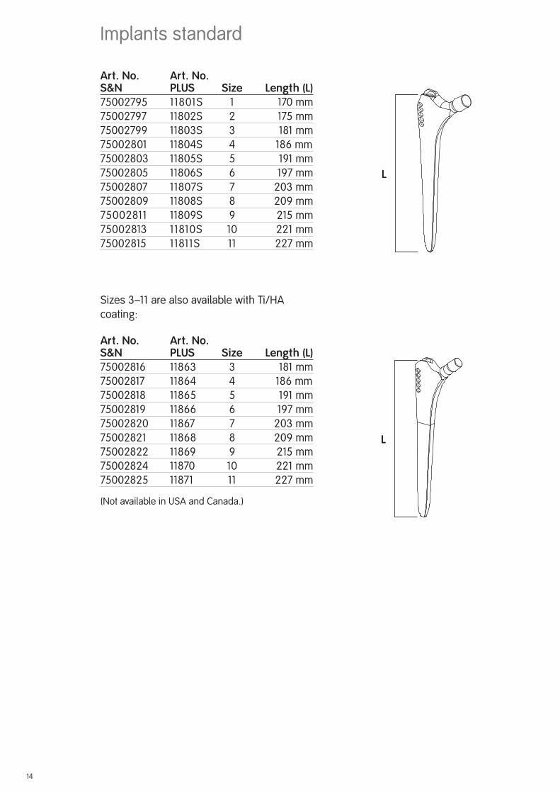
Art. No. Art. No.S&N PLUS Size ...... Length (L)75002795 11801S 1 ..............170 mm75002797 11802S 2 ............. 175 mm75002799 11803S 3 .............. 181 mm75002801 11804S 4 186 mm75002803 11805S 5 .............. 191 mm75002805 11806S 6 ............. 197 mm75002807 11807S 7 ............ 203 mm75002809 11808S 8 ............ 209 mm75002811 11809S 9 ............. 215 mm75002813 11810S 10 ............221 mm75002815 11811S 11 .............227 mm
Sizes 3–11 are also available with Ti/HA coating:
Art. No. Art. No.S&N PLUS Size ...... Length (L)75002816 11863 3 .............. 181 mm75002817 11864 4 186 mm75002818 11865 5 .............. 191 mm75002819 11866 6 ............. 197 mm75002820 11867 7 ............ 203 mm75002821 11868 8 ............ 209 mm75002822 11869 9 ............. 215 mm75002824 11870 10 ............221 mm75002825 11871 11 .............227 mm
(Not available in USA and Canada.)
Implants standard
L
14
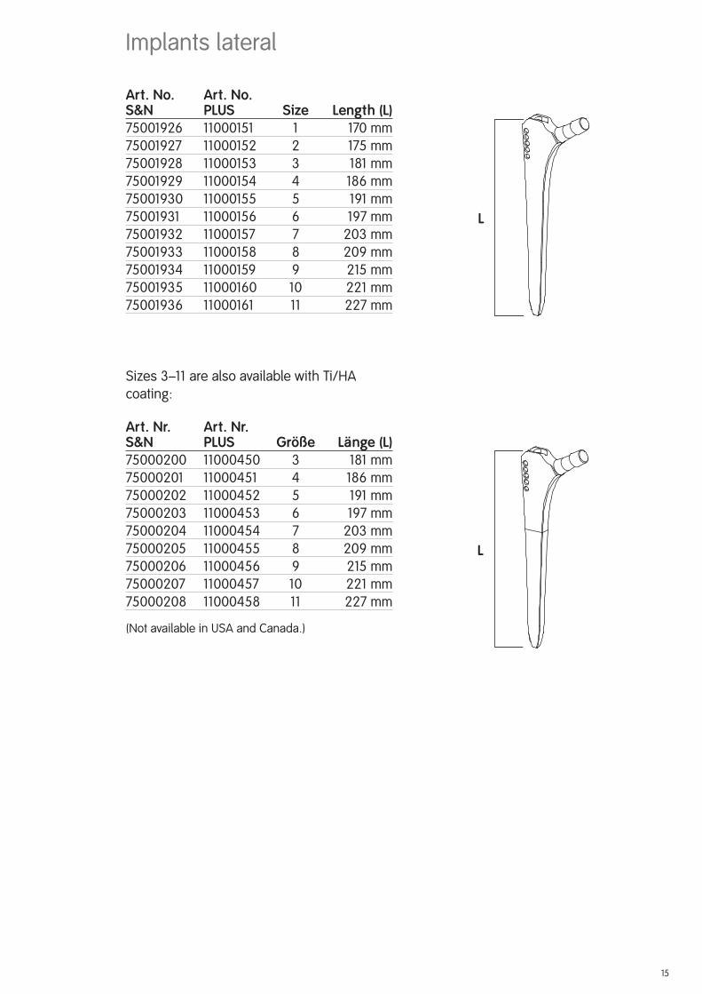
Art. No. Art. No.S&N PLUS Size ..... Length (L)75001926 11000151 1 .............170 mm75001927 11000152 2 ............ 175 mm75001928 11000153 3 ............. 181 mm75001929 11000154 4 ............ 186 mm75001930 11000155 5 ............. 191 mm75001931 11000156 6 ............ 197 mm75001932 11000157 7 ........... 203 mm75001933 11000158 8 ........... 209 mm75001934 11000159 9 ............ 215 mm75001935 11000160 10 ...........221 mm75001936 11000161 11 ...........227 mm
Sizes 3–11 are also available with Ti/HA coating:
Art. Nr. Art. Nr.S&N PLUS Größe .....Länge (L)75000200 11000450 3 ............. 181 mm75000201 11000451 4 ............ 186 mm75000202 11000452 5 ............. 191 mm75000203 11000453 6 ............ 197 mm75000204 11000454 7 ........... 203 mm75000205 11000455 8 ........... 209 mm75000206 11000456 9 ............ 215 mm75000207 11000457 10 ...........221 mm75000208 11000458 11 ...........227 mm
(Not available in USA and Canada.)
Implants lateral
L
L
15
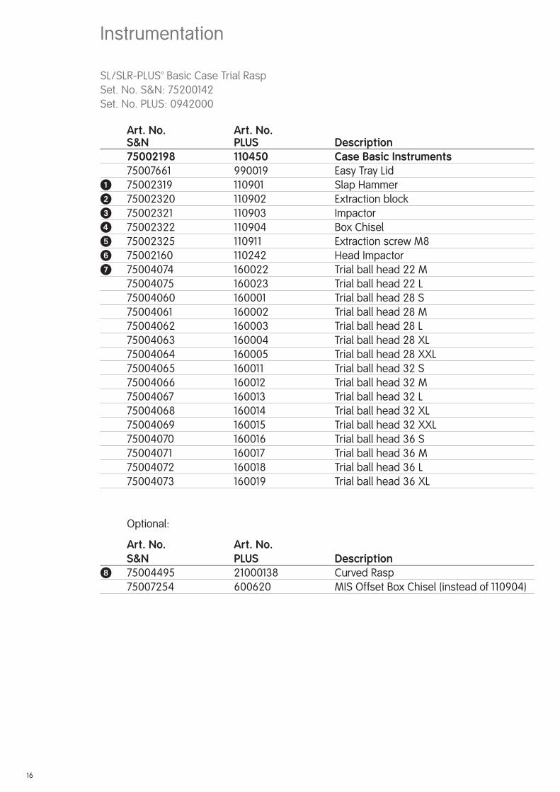
Instrumentation
SL/SLR-PLUS™ Basic Case Trial RaspSet. No. S&N: 75200142Set. No. PLUS: 0942000
Art. No. Art. No. S&N PLUS Description 75002198 110450 Case Basic Instruments 75007661 990019 Easy Tray Lid� 75002319 110901 Slap Hammer� 75002320 110902 Extraction block� 75002321 110903 Impactor� 75002322 110904 Box Chisel� 75002325 110911 Extraction screw M8� 75002160 110242 Head Impactor� 75004074 160022 Trial ball head 22 M 75004075 160023 Trial ball head 22 L 75004060 160001 Trial ball head 28 S 75004061 160002 Trial ball head 28 M 75004062 160003 Trial ball head 28 L 75004063 160004 Trial ball head 28 XL 75004064 160005 Trial ball head 28 XXL 75004065 160011 Trial ball head 32 S 75004066 160012 Trial ball head 32 M 75004067 160013 Trial ball head 32 L 75004068 160014 Trial ball head 32 XL 75004069 160015 Trial ball head 32 XXL 75004070 160016 Trial ball head 36 S 75004071 160017 Trial ball head 36 M 75004072 160018 Trial ball head 36 L 75004073 160019 Trial ball head 36 XL
Optional:
Art. No. Art. No. S&N PLUS Description 75004495 21000138 Curved Rasp 75007254 600620 MIS Offset Box Chisel (instead of 110904)
16

�
�
�
��
�
�
OPTIONAL
17
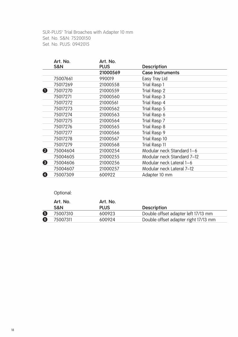
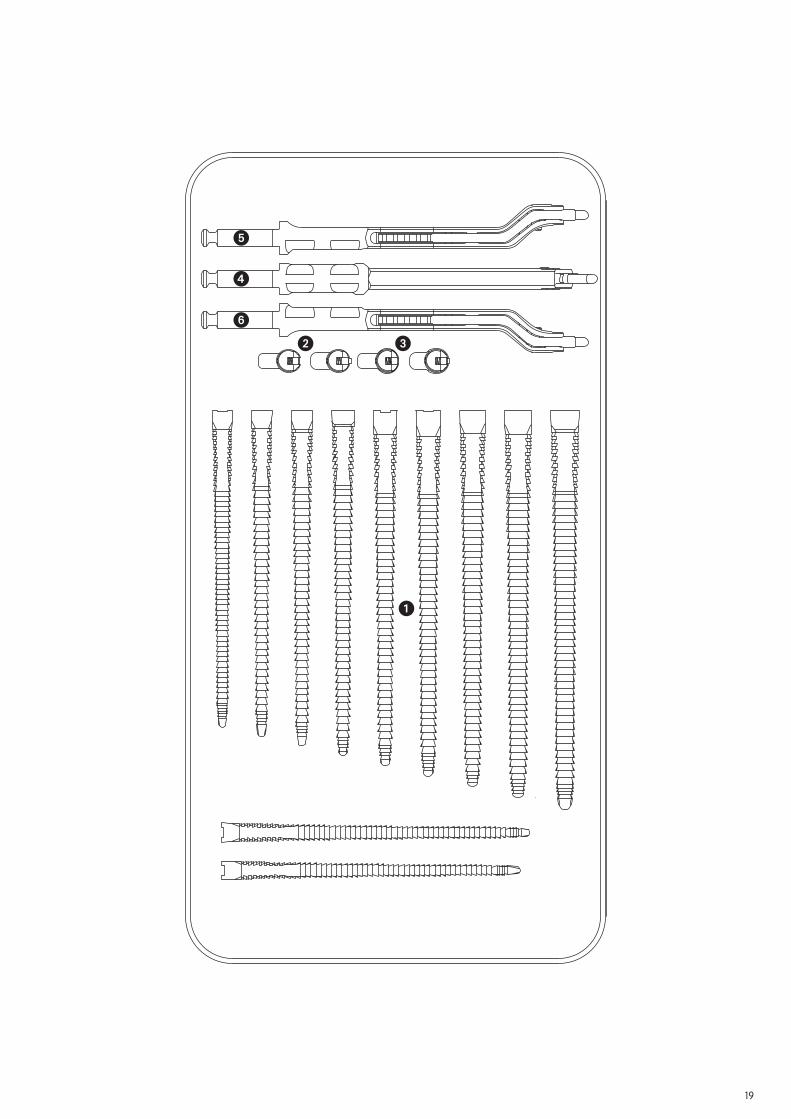
SLR-PLUS™ Trial Broaches with Adapter 10 mmSet. No. S&N: 75200150Set. No. PLUS: 0942015
Art. No. Art. No. S&N PLUS Description 2100056975002198 Case Instruments 75007661 990019 Easy Tray Lid 75017269 21000558 Trial Rasp 1� 75017270 21000559 Trial Rasp 2 75017271 21000560 Trial Rasp 3 75017272 21000561 Trial Rasp 4 75017273 21000562 Trial Rasp 5 75017274 21000563 Trial Rasp 6 75017275 21000564 Trial Rasp 7 75017276 21000565 Trial Rasp 8 75017277 21000566 Trial Rasp 9 75017278 21000567 Trial Rasp 10 75017279 21000568 Trial Rasp 11� 75004604 21000254 Modular neck Standard 1–6 75004605 21000255 Modular neck Standard 7–12� 75004606 21000256 Modular neck Lateral 1–6 75004607 21000257 Modular neck Lateral 7–12� 75007309 600922 Adapter 10 mm
Optional:
Art. No. Art. No. S&N PLUS Description� 75007310 600923 Double offset adapter left 17/13 mm� 75007311 600924 Double offset adapter right 17/13 mm
18
�
�
�
� �
�
19
Sterilization
20
Implants
All the implants described in this surgical technique are supplied by the manufacturer in a sterile condition. Resterilization is not allowed.
Instruments
The system instruments are non-sterile when delivered. Before use, they must be cleaned by the usual methods in accordance with hospital regulations and sterilized in an autoclave in accordance with the national legal regulations and recommendations. (For detailed infor-mation please refer to the leafl et Lit. No. 1363.)
For correct settings, refer to the user instructions issued by the autoclave manufacturer. Instru ment manufacturers and dealers do not accept any responsibility for the sterilization of products by the customer.


ManufacturerSmith & Nephew Orthopaedics AG For further information please contactErlenstrasse 4a our local sales offi ce.6343 Rotkreuz www.smith-nephew.com Switzerland
™Trademark of Smith & Nephew Lit. No. 1751-e Europa Ed. 03/08 300 Ex. 11/07 0 1 2 3


![A cementless, proximally fixed anatomic femoral stem ...bone interfaces inhibited bone ingrowth when the micro-motion exceeded 150 mm [10,11]. We hypothesized that a cementless, anatomic](https://static.documents.pub/doc/80x56/5e63476c137d81362d557525/a-cementless-proximally-fixed-anatomic-femoral-stem-bone-interfaces-inhibited.jpg)


