Note: The original, authoritative version of this manual is the English version produced by CTB, Inc. or any of its subsidiaries or divisions, (hereafter collectively referred to as "CTB"). Subsequent changes to any manual made by any third party have not been reviewed nor authenticated by CTB. Such changes may include, but are not limited to, translation into languages other than English, and additions to or deletions from the original content. CTB disclaims responsibility for any and all damages, injuries, warranty claims and/or any other claims of any nature associated with such changes, inasmuch as such changes result in content that is different from the authoritative CTB-published English version of the manual. For current product installation and operation information, please contact the customer service and/or technical service departments of the appropriate CTB subsidiary or division. Should you observe any questionable content in any manual, please notify CTB immediately in writing directed to: CTB Legal Department, P.O. Box 2000, Milford, IN 46542-2000 USA. INSTALLATION AND OPERATION MANUAL Made to Work. Built to Last. SM P.O. Box 2000 State Road 15 North Milford, IN. 46542-2000 U.S.A. 574-658-4101 Fax 877-730-8825 www.ctbinc.com CN2169 CENTER BELT COLLECTION TABLE
Transcript
Note: The original, authoritative version of this manual is the English version produced by CTB, Inc. or any of its subsidiaries or
divisions, (hereafter collectively referred to as "CTB"). Subsequent changes to any manual made by any third party have not
been reviewed nor authenticated by CTB. Such changes may include, but are not limited to, translation into languages other
than English, and additions to or deletions from the original content. CTB disclaims responsibility for any and all damages,
injuries, warranty claims and/or any other claims of any nature associated with such changes, inasmuch as such changes result
in content that is different from the authoritative CTB-published English version of the manual. For current product installation
and operation information, please contact the customer service and/or technical service departments of the appropriate CTB
subsidiary or division. Should you observe any questionable content in any manual, please notify CTB immediately in writing
directed to: CTB Legal Department, P.O. Box 2000, Milford, IN 46542-2000 USA.
INSTALLATION AND OPERATION MANUAL
Made to Work. Built to Last. SM
P.O. Box 2000 State Road 15 North
Milford, IN. 46542-2000 U.S.A.
574-658-4101 Fax 877-730-8825
www.ctbinc.com
CN2169
CENTER BELT COLLECTION TABLE
pg. 2CTB Center Belt Table Manual
Manufacturer warrants each new product manufactured by it to be free from defects in material or workmanship
for one (1) year from and after the date of initial installation by or for the original purchaser. If such a defect is
found by Manufacturer to exist within the one-year period, the Manufacturer will, at its option, (a) repair or
replace such product free of charge, F.O.B. the factory of manufacture, or (b) refund to the original purchaser the
original purchase price, in lieu of such repair or replacement. Labor costs associated with the replacement or
repair of the product are not covered by the Manufacturer.
Conditions and Limitations1. The product must be installed by and operated in accordance with the instructions published
by the Manufacturer or Warranty will be void.
2. Warranty is void if all components of the system are not original equipment supplied by the
Manufacturer.
3. This product must be purchased from and installed by an authorized distributor or installer or a
certified representative thereof or the Warranty will be void.
4. Malfunctions or failure resulting from misuse, abuse, negligence, alteration, accident, or lack
of proper maintenance, or from lightning strikes, electrical power surges or interruption of
electricity, shall not be considered defects under the Warranty.
5. This Warranty applies only to systems for the care of poultry and livestock. Other applications
in industry, commerce, or residential applications are not covered by this Warranty and are
strictly prohibited. Any such use will void the Warranty.
Manufacturer shall not be liable for any Consequential or Special Damage which any purchaser may suffer or
claim to suffer as a result of any defect in the product. "Consequential" or "Special Damages" as used hereininclude, but are not limited to, lost or damaged products or goods, costs of transportation, lost sales, lost orders,lost income, increased overhead, labor and incidental costs and operational inefficiencies.
THIS WARRANTY CONSTITUTES THE MANUFACTURER'S ENTIRE AND SOLE WARRANTY AND
THIS MANUFACTURER EXPRESSLY DISCLAIMS ANY AND ALL OTHER WARRANTIES, INCLUDING,
BUT NOT LIMITED TO, EXPRESS AND IMPLIED WARRANTIES AS TO MERCHANTABILITY, FITNESS
FOR PARTICULAR PURPOSES SOLD AND DESCRIPTION OR QUALITY OF THE PRODUCT
FURNISHED HEREUNDER.
Distributors are not authorized to modify or extend the terms and conditions of this Warranty in any manner or to
offer or grant any other warranties for the products in addition to those terms expressly stated above. An officer
of the Manufacturer must authorize any exceptions to this Warranty in writing. Manufacturer reserves the right to
change models and specifications at any time without notice or obligation to improve previous models.
Effective 01/07
WARRANTY
CENTER BELT COLLECTION TABLE AND V SPEED CONTROLINSTALLATION AND OPERATION MANUAL
pg. 3 CTB Center Belt Table Manual
WARNING: Improper installation, adjustment, alteration, service or maintenance can cause property damage, injury or death. Readthe installation, operating and maintenance instructions thoroughly before installing or servicing this equipment.
L'installation déplacée, l'ajustement, le changement, le service ou l'entretien peuvent causer les dommages de propriété, la blessure ou lamort. Lire l'installation, fonctionnant et les instructions d'entretien à fond avant d'installer ou entretenir cet équipement.
La instalación impropia, ajuste, modificación, servicio o mantenimiento puede causar dañado propiedad, herida o muerte.Lea la instalación, trabajar y mantenimiento instrucciones completamente antes de instalar o poner en funcionamiento equipo.
PARTS LIST AND ASSEMBLY INSTRUCTIONS FOR CENTER BELT COLLECTION TABLE
This guide will address the assembly of and parts identification for the revised center belt collection
table. Maintence and repair of the unit is also covered in this manual.
DANGER !Shock hazard exists! Disconnect all power before opening enclosure for servicing. Allow 5 minutes poweroff for capacitor to discharge on circuit board. Control must be grounded.
Danger de choc existe! Débrancher tout pouvoir électrique avant d'ouvrir le couvercle. Permettre cinq minutes pour le condensateur pour décharger. Contrôle électronique doit avoir fil de terre.
Calambre peligro existe! Desconecte todo energía eléctrica de controlar antes de abrir la tapa. Permitacinco minutos para condensador de descargar antes de abrir. El control se debe moler.
DANGER !Beware of pinch point between the small roll (Pinch Roll) and the large roll (Drive Roll) in belt conveyor
drive unit.
Avoir conscience de pincer endroit entre le troisième petit rouleau et le quatrième grand rouleau danstransporteuse corroie contrôle.
Tener cuidado de el pellizco punto en medio el tercera pequeño rollo y el cuarta grande rollo en el trans-portador del cinturón unidad.
DANGER !Take necessary precautions when working with sheet metal, edges may be SHARP!Faites attention quand travaillant avec feuillet, les bords peuvent être AIGUISÉ !
¡Tome las precauciones necesarias al trabajar con metal laminado, las orillas pueden ser AGUDAS!
CTB Center Belt Table Manual pg. 4
24
26 27
28
29
25
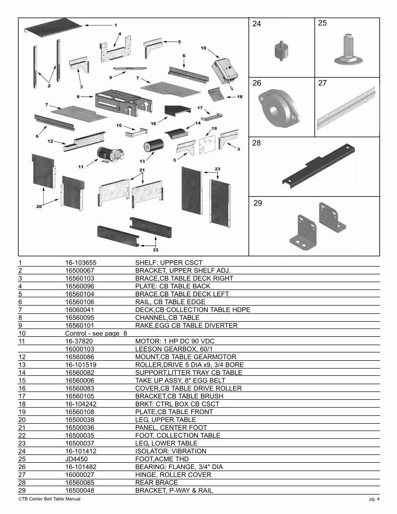
1 16-103655 SHELF: UPPER CSCT
2 16500067 BRACKET, UPPER SHELF ADJ.
3 16560103 BRACE,CB TABLE DECK RIGHT
4 16560096 PLATE: CB TABLE BACK
5 16560104 BRACE,CB TABLE DECK LEFT
6 16560106 RAIL, CB TABLE EDGE
7 16060041 DECK,CB COLLECTION TABLE HDPE
8 16560095 CHANNEL,CB TABLE
9 16560101 RAKE,EGG CB TABLE DIVERTER
10 Control - see page 8
11 16-37820 MOTOR: 1 HP DC 90 VDC
16000103 LEESON GEARBOX, 60/1
12 16560086 MOUNT,CB TABLE GEARMOTOR
13 16-101519 ROLLER,DRIVE 5 DIA x9, 3/4 BORE
14 16560082 SUPPORT,LITTER TRAY CB TABLE
15 16560006 TAKE UP ASSY, 8" EGG BELT
16 16560083 COVER,CB TABLE DRIVE ROLLER
17 16560105 BRACKET,CB TABLE BRUSH
18 16-104242 BRKT: CTRL BOX CB CSCT
19 16560108 PLATE,CB TABLE FRONT
20 16500038 LEG, UPPER TABLE
21 16500036 PANEL, CENTER FOOT
22 16500035 FOOT, COLLECTION TABLE
23 16500037 LEG, LOWER TABLE
24 16-101412 ISOLATOR: VIBRATION
25 JD4450 FOOT,ACME THD
26 16-101482 BEARING: FLANGE, 3/4" DIA
27 16000027 HINGE, ROLLER COVER
28 16560085 REAR BRACE
29 16500048 BRACKET, P-WAY & RAIL
pg. 5 CTB Center Belt Table Manual
IDLER BELT ASSEMBLY
16560080
1 16560079 DUST COVER,CB IDLER ROLLER ASM
2 16560078 BRACKET,BRUSH CB IDLER ROLLER
3 16-35572 BRUSH: TAMPICO WHT 5" x 1-1/2"
4 16-104224 SHAFT: PINCH ROLL CB CSCT
5 16-101566 ROLLER,PLASTIC 1.5ODx.66IDx11
6 16560063 MOUNT BRKT(L),SB IDLER ROLLER
7 16560062 MOUNT BRKT(R),SB IDLER ROLLER
8 16560081 FRAME, CB REAR RETURN MOUNT
9 16-8904 CLAMP: HINGE SS 3/8 WIDE
10 16000006 BOLT,CARR SHORT NECK 5/16x3/4
11 16-35631 NUT: HEX FLG LCK 5/16-18 PLTD
12 16-33139 RIVET:POP 3/16" ALUM -LONG-
9
10
11
12
pg. 6CTB Center Belt Table Manual
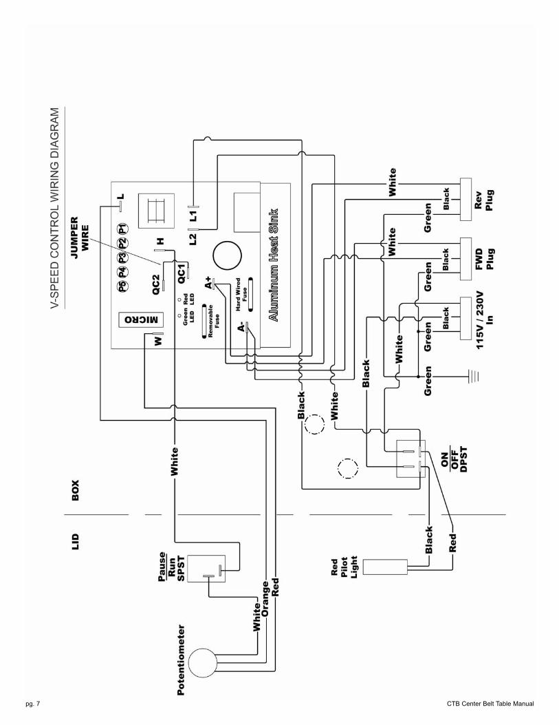
Adjustment Procedure for the Gemini DC Variable Speed Control Board
Model 12M04-00222 w/5M12-46 Chip (120V) or w/5M12-41 Chip (240V)
ALL ADJUSTMENT MUST BE DONE WITH A FULL BELT SYSTEM OR SIMULATED LOAD ON THEMOTOR
1. With the main power off, turn the Speed Control on the front of the control box counterclockwise
until it stops. This will be the minimum speed setting. Open the control box. Attach probes to
read Voltage between A+ and A- terminals as labeled on the board. Turn the main power switch
ON. Adjust the MIN SPEED potentiometer (P1) on the circuit board so that the voltage is
between 0 and 5 VDC.
2. Turn the main power OFF. Turn the speed control located on the front of the control box
clockwise until it stops. This will be the maximum speed setting. Open the control box and
attach the probe to read voltage between A+ and A- terminals. Turn the main power switch ON.
Adjust the MAX SPEED potentiometer (P2) on the circuit board so that the voltage is between
112 and 116 VDC.
3. Adjust the I.R. COMP potentiometer (P3) on the circuit board to 1/4 travel from full counterclock
wise. Turn the P3 Potentiometer slowly clockwise until you can hear the motor RPM oscillate,
and then back off slightly from that point. If the belt stalls during normal operation, increase the
P3 set point gradually by turning the P3 potentiometer clockwise. When properly adjusted, the
motor will be able to hold speed with sudden increases in the loading without P3 set at full
clockwise.
4. The ACCEL potentiometer (P4) an adjustment for belt starting acceleration. When set fully
counterclockwise, it will operate with instant motor drive acceleration (rapid). With P4 turned fully
clockwise, the motor accelerate the slowest. This can be set to the operator's preference, but ¼
turn from full counterclockwise is recommended..
5. Set the CURRENT LIMIT (P5) to fully clockwise and then back off slightly. The control current
limit is set at 11 amps DC instantaneous when set at maximum and is predetermined by the
components installed on the board.
6. The removable fuse is an 8 amp slow-blow type such as an MDA-8
7. The Green LED on the circuit board indicates Power ON.
8. The Red LED on the circuit board indicates CURRENT LIMIT is activated.
Revised 2/16/06
pg. 7 CTB Center Belt Table Manual
pg. 8CTB Center Belt Table Manual
1 16000047 BOOT, TOGGLE SWITCH
2 13005282 SWITCH TOGGLE SING PO
3 15100589 PILOT LIGHT 250 VOLT
4 16500088 LID, V-SPEED CONTROL
5 16-101540 POTENTIOMETER: & KNOB
6 16000126 FUSE: 8 AMP SLOW BLOW
(MDA-8)
7 16500065 BOARD,CRCT PRPROG
120VAC/90VDC
16500064 BOARD,CRCT PRPROG
240VAC/90VDC
8 16500087 BOX: V-SPEED CONTROL
9 30863 PIVOT,CNTL BOX LATCH
10 30862 LATCH,CNTL BOX
11 16500084 BASE PLATE W/WELD STUDS
12 16-101524 DISCONNECT: QUICK, FEM
13 13008107 WIRE STRAIN RELIEF
14 16060017 PLUG, ELEC 230V NEMA 6-15P
15 16-10062 CORD: SJT-O W/PLUG 14/3
16 13005283 SWITCH TOGGLE DOUBLE
COMPLETE ASSEMBLIES:
16500061 CONTROL, V-SPD 240VAC/90VDC
16500062 CONTROL, V-SPD 120VAC/90VDC
COMPONENT PARTS
TABLE CONTROL - Variable Speed DC
STEP 4. Attach Upper Deck to Back of Table.
Using Carriage bolts, flange nuts provided.
pg. 9 CTB Center Belt Table Manual
STEP 1. Install Plastic Feet (as shown).
STEP 2. LEG ADJUSTMENT.
TABLE SET-UP AND ASSEMBLY
STEP 3. BASE ADJUSTMENT (if needed).
STEP 5.Attach Control Box to Mounting
Bracket using the two 1/4 -14 by 3/4” screws provided.
Position Control and
Bracket as shown.
Alternate mounting
position on the
Upper Shelf Bracket.
Attach the End Roller Assembly to the nest Center Plate using Pop
Rivets via the three holes shown in the illustration left. Dust cover
removed for clarity.
Return Roller Assembly
Step 6.Install Rear Return Roll Assembly to last nest.
Nest Center Plate
3 Holes
CTB Center Belt Table Manual pg. 10
BELT INSTALLATION
NEST SYSTEMLift nest system if winch is used, to facilitate threading of belt. If winch is not used, follow the same pro-
cedure with system sitting on slats.
Thread conveyor belt from the drive end. Insert pipe or rod through roll of belt. Pull belt off roll through
top of conveyor tray to return end at back of house. Thread belt around idler roll and thread belt over
belt guides in nest on return run to table.
See detail “A” on
next page
NOTE: Safety guards must be in place when in
table is in operation.
CTB Center Belt Table Manualpg. 11
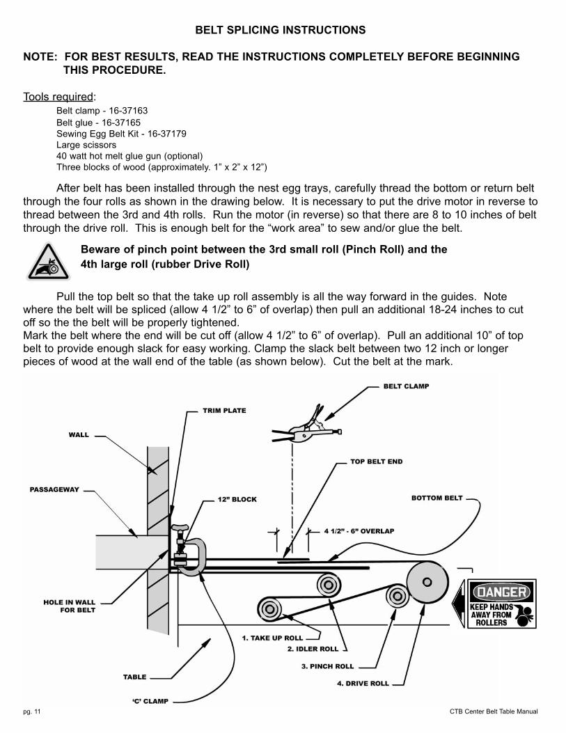
BELT SPLICING INSTRUCTIONS
NOTE: FOR BEST RESULTS, READ THE INSTRUCTIONS COMPLETELY BEFORE BEGINNING THIS PROCEDURE.
Tools required:
Belt clamp - 16-37163
Belt glue - 16-37165
Sewing Egg Belt Kit - 16-37179
Large scissors
40 watt hot melt glue gun (optional)
Three blocks of wood (approximately. 1” x 2” x 12”)
After belt has been installed through the nest egg trays, carefully thread the bottom or return belt
through the four rolls as shown in the drawing below. It is necessary to put the drive motor in reverse to
thread between the 3rd and 4th rolls. Run the motor (in reverse) so that there are 8 to 10 inches of belt
through the drive roll. This is enough belt for the “work area” to sew and/or glue the belt.
Beware of pinch point between the 3rd small roll (Pinch Roll) and the 4th large roll (rubber Drive Roll)
Pull the top belt so that the take up roll assembly is all the way forward in the guides. Notewhere the belt will be spliced (allow 4 1/2” to 6” of overlap) then pull an additional 18-24 inches to cutoff so the the belt will be properly tightened. Mark the belt where the end will be cut off (allow 4 1/2” to 6” of overlap). Pull an additional 10” of topbelt to provide enough slack for easy working. Clamp the slack belt between two 12 inch or longerpieces of wood at the wall end of the table (as shown below). Cut the belt at the mark.
CTB Center Belt Table Manual pg. 12
An over tightened belt causes decreased belt life, poor performance and excessive wear on the
drive system. The belt may become cupped and allow eggs to go underneath it. The belt may
become permanently creased. The belt should be pulled snug and slightly stretched, using the
method described here.
Be sure to leave enough slack in the belt at the splice area for the following cutting/sewing operations.
Cut the belt as shown, with tapered ends.
Use a cigarette lighter or match to singe the cut edges of the belt to deter unravelling of the
fibers. A minor singe is adequate.
NOTE: Be sure not to over singe the edges (identified by extreme indentations into the belt).
Overlap the belt ends approximately 4” to 6” so that when the
belt is pulled toward the table, the end that is pulling is on
the bottom. (This will keep the belt edge from catching or
snagging on the joints in the passageway.)
Apply a 1/4” bead of glue across the middle splice area on
bottom belt (as shown in drawing).
Note sewing pattern in drawing. Avoid glue in sewing pattern
as it is difficult to sew through glued belt.
NOTE: The splice MUST be made within 15 seconds from the time
application of glue is started.
Work fast, align edges and press together. Immediately apply belt clamp over splice. Clamp
and lock for 60 seconds.
Take the needle and waxed thread out of the Belt Sewing Kit (part 16-37179 or equivalent
substitute). Cut approximately six feet of the waxed thread and thread it through the needle.
Use a 1/4” running stich on the sides and a whip stich with 1/4” minimum between the singed
edge and the interior of the belt. Knot thread, leaving end to tie off and sew the belt together up
the right edge, along the top of the belt splice and down the left edge.
Without cutting the thread, turn the belt over and sew along the bottom belt splice. Tie off the
start and end threads.
To protect the splice, hot glue over whip sewn ends only. Gluing over the sides will create a stiff, board-like splice that will not flow well over rolls.
Use belt clamp to flatten glued ends.
Switch on drive motor and watch for constant sag in belt beneath table. If sag occurs, either
the belt is catching or it is too long.
If belt is catching, find the point of restriction and release belt.
To reduce the length of the belt, cut out excess at an existing splice and re-splice the belt.
Check for proper belt clearance and repeat until belt moves freely through tray.
The belt may stretch some over time. When belt stretches beyond the action of the pinch roll
adjuster, cut the belt at an existing splice, remove excess and re-splice.
Do not splice belt using glue only!You may sew only, but using glue AND sewing is recommended.
CAUTION! When using hot glue, do not let it come in contact
with skin!
NOTE: DO NOT OVER TIGHTEN THE BELT
CTB Center Belt Table Manualpg. 13
When placing the nest system on slats, whether wooden or plastic, Agile Mfg. requires that the nest line
be level along the entire length of the line. This can be accomplished by placing 1” x 4” strips over the
slats and underneath the nests as a base to shim the nests.
minimum
strip
length
CTB Center Belt Table Manual pg. 14
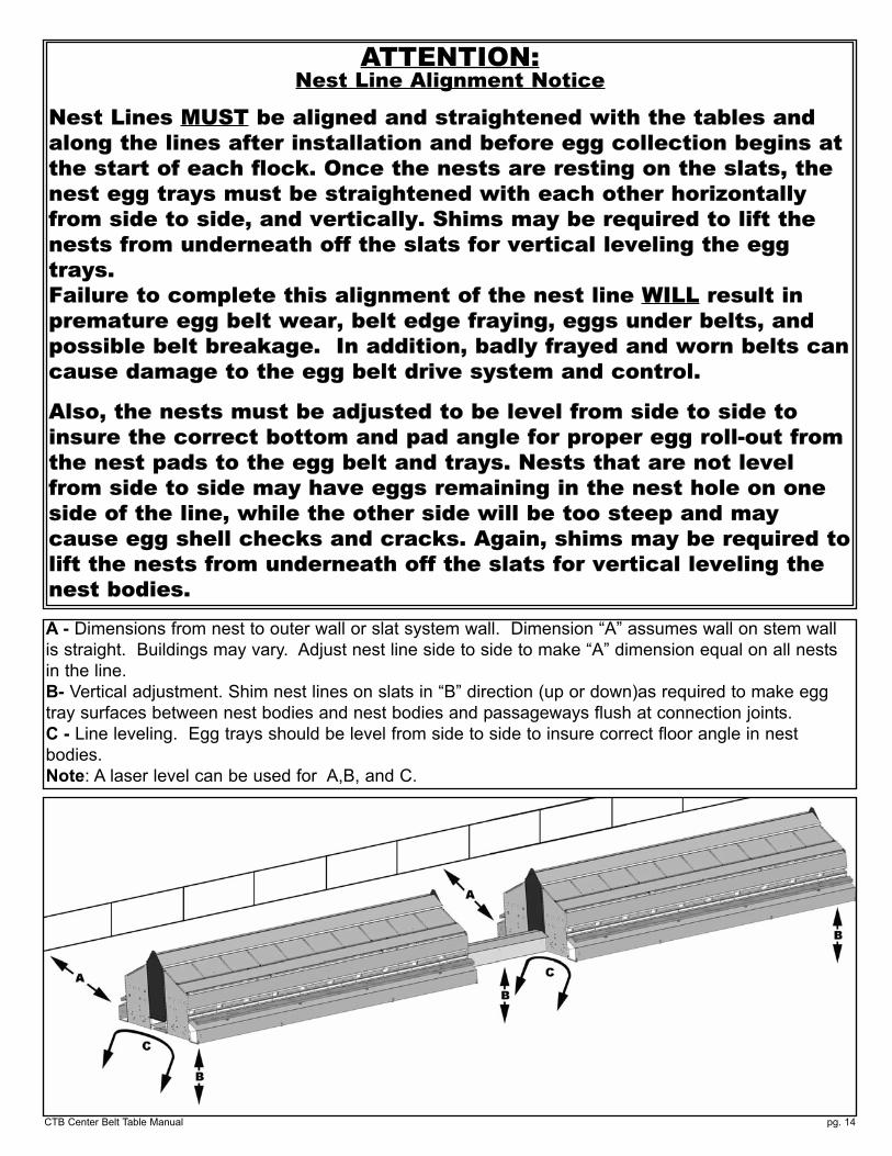
ATTENTION:Nest Line Alignment Notice
Nest Lines MUST be aligned and straightened with the tables andalong the lines after installation and before egg collection begins atthe start of each flock. Once the nests are resting on the slats, thenest egg trays must be straightened with each other horizontallyfrom side to side, and vertically. Shims may be required to lift thenests from underneath off the slats for vertical leveling the eggtrays. Failure to complete this alignment of the nest line WILL result inpremature egg belt wear, belt edge fraying, eggs under belts, andpossible belt breakage. In addition, badly frayed and worn belts cancause damage to the egg belt drive system and control.
Also, the nests must be adjusted to be level from side to side toinsure the correct bottom and pad angle for proper egg roll-out fromthe nest pads to the egg belt and trays. Nests that are not levelfrom side to side may have eggs remaining in the nest hole on oneside of the line, while the other side will be too steep and maycause egg shell checks and cracks. Again, shims may be required tolift the nests from underneath off the slats for vertical leveling thenest bodies.
A - Dimensions from nest to outer wall or slat system wall. Dimension “A” assumes wall on stem wall
is straight. Buildings may vary. Adjust nest line side to side to make “A” dimension equal on all nests
in the line.
B- Vertical adjustment. Shim nest lines on slats in “B” direction (up or down)as required to make egg
tray surfaces between nest bodies and nest bodies and passageways flush at connection joints.
C - Line leveling. Egg trays should be level from side to side to insure correct floor angle in nest
bodies.
Note: A laser level can be used for A,B, and C.
CTB Center Belt Table Manualpg. 15
PINCH ROLL ADJUSTMENTThere is a spring and pressure rod assembly on both sides of each belt line and drive roller/pinch roller assembly.
To increase pinch roller pressure, loosen the jam nuts on each pressure rod and tighten the pressure adjust-ment nuts as needed to prevent belt slippage. The springs are pre-set at the factory, compressed to 2 1/8”.Adjust as required.
16560071 PASSAGEWAY,8" X 18" SS CBN KIT16-104169 COVER: P-WAY SS 18" SCB16-104163 TRAY: PASSAGEWAY 18" SC
16560072 PASSAGEWAY,8" X 24" SS CBN KIT16-104170 COVER: P-WAY SS 24" SCB16-104164 TRAY: PASSAGEWAY 24" SC
16560073 PASSAGEWAY,8x28-3/4 SS CBN KIT16-104171 COVER: P-WAY SS 28-3/4"16-104165 TRAY:PASSAGEWAY 28-3/4"
16560074 PASSAGEWAY,8" X 36" SS CBN KIT16-104172 COVER: P-WAY SS 36" SCB16-104166 TRAY: PASSAGEWAY 36" SC
16560075 PASSAGEWAY,8" X 48" SS CBN KIT16-104173 COVER: P-WAY SS 48" SCB16-104167 TRAY: PASSAGEWAY 48" SC
16560068 ANGLE,C.BELT P-WAY SPPT UNIV.16-33139 RIVET: POP 3/16" AL AD64ABS LG
16-34096 RIVET: POP 3/16" AL AD62ABS SH
PASSAGEWAY COMPONENTS
Each KIT contains Cover, Tray, Rivets and Support Angle.
Stainless Steel Cover
Galvanized Tray
1/6” Difference
pg. 16CTB Center Belt Table Manual
OPERATIONAL MAINTENANCE
- The Gearmotor assembly and drive shaft Bearings installed on the table are sealed and
permanently lubricated. There are no ports or zerks on the bearings to apply additional
lubrication. Replacement oil for the Gearbox and Reducer use MOBILE SHC634 available from
WW Grainger.
If a problem develops with the Gearmotor or Bearings, the drive system is overloaded due to
issues with the belt runs. Check the system for the following possible problems:
a. Belts snags and or restrictions in the return side (underside) of the egg trays and
nests,
b. Over-tightened or jammed cleaning brushes,
c. Mis-aligned egg trays and/or passageways,
d. Rollers in the table and or return assemblies that do not rotate freely,
e. Belt has been installed in the table incorrectly,
f. Belt splices are oversized (wider than belt width) or splice is poor & unraveling
causing it to hang up,
g. Belt tension is too great,
h. Belt slack adjustment assembly is jammed and cannot slide,
i. Belt tracking is out of adjustment at the front and back of conveyor.
j. Belt is rolled over or creased,
k. Table not aligned with nest line.
- Lubricate the plastic rollers in the table and return roller assemblies with a silicon or graphite
base spray lubricant.
DO NOT USE WD-40 OR OTHER TYPES OF PETROLEUM BASED SPRAY LUBRICANTS.
The rollers will absorb petroleum based lubricants, causing the rollers to swell and become more
restricted.
- Check the belt tension periodically If the belt stretch exceeds the slack take-up action in the
table, cut out a section of belt at an existing field splice and re-splice to shorten the overall
length.
- Check the belt splices periodically. This can be done while collecting eggs. If the splice is
ragged, frayed, or worn, trim and re-fasten.
- Check the belt brushes and adjust as required. With the sweeping action properly adjusted, the
wear on the brush should be minor. See Brush Position on page 9 .
- Check the table drive rollers for wear and buildup. Clean as required. Keep all safety guards in
place during operation to avoid accidents and injury.
- Clean the plastic egg gathering deck regularly with soap and water to keep the incoming eggs
free of contamination from broken eggs and manure.
- Clean the egg belts regularly per the guidelines specified by your Poultry Company.
- Clean the cooling fan on the gearmotor and throughout the inside of the table with compressed
air or a blower. DO NOT clean with liquids of any type.
pg. 17 CTB Center Belt Table Manual
EGG BELT CARE
The following are recommendations for the care and maintenance of the egg collection belt.
The belt is warranted against manufacturing defects.
Inspect belt during installation and after final adjustments have been made.
Install belt as per provided instruction:
- Shim nests so that they are level and the belt is traveling on a level plane.
- Assemble equipment properly so that there are no sharp edges or rivet ends in or
obstructing the path of the belt.
- Align system (including the table) so that the belt is in a straight line from the table drive
rollers to the return rollers at the back.
- Make sure that the belt splices are not wider than the belt itself and that all joints are
straight and true.
Keep the belt clean. (Follow instructions of your integrator as to what may be used to clean
the belt).
- Clean up any broken eggs or debris and sanitize (remove all residue as applicable)
If picking, snags, tears, or any other evidence of trouble occurs in or on the belt, immediately
investigate and correct the problem.
- Check for rodents in the house. Rodent damage to belts will cause snags, jams and
possible table damage.
- Check tracking of the belt. (It should be traveling down the center of the tray, not against
the edges)
- Check for proper installation of the equipment. (sharp edges or rivet ends in or
obstructing the path of the belt)
pg. 18CTB Center Belt Table Manual
MANAGEMENT GUIDE
PRE LAY PERIOD1. As hens are put in house, place on slats (if winched, nest can be raised initially to encourage
traffic to feed and water).
2. Nest should remain closed in order to train the birds not to roost in the nest. Once birds are near lay or first egg has been found, the nest should be opened.
INITIAL START OF LAY3. When the first egg is found, a diligent program must be initiated.
A. Search for floor and slat eggs at least four times in the morning and two times
during the afternoon.
NOTE: DO NOT disturb birds inside the nest to assure them that the nest is a secure
place to lay.
B. Place the eggs either on the conveyor belt or in baskets as per instructions of the
contracting company.
C. DO NOT allow eggs to accumulate in any specific location. This will deter other hens
from laying in the same spot and encourage them to use the nest.
D. Care should be taken not to disrupt hens in the nest.
4. During start up, floor and slat eggs will be at a higher percentage than what will be achieved
later in the flock but will reach a very satisfactory level when this guide is followed.
5. Close nest after last collection and re-open after lights go off.
Note: This will train the birds not to sit in nest at night or perch on the stringer.
PRODUCTION PERIOD6. Collect eggs at least four times per day or as per instructions of the contracting company.
7. Do not allow eggs to build up on the tables during collection. This can cause cracks and
cross-contamination of eggs.
8. Continue to monitor floor and slat eggs at least four times per day for the remainder of the
flock.
9. Clean belt debris early each morning by running belt one complete revolution.
10. Any wet manure or broken eggs should be removed from the belts or nests immediately.
11. Check brushes at rear of house periodically during each flock to ensure proper cleaning.