100
CENTER ONE Single-Channel Vacuum Gauge Controller Operating Manual GA 09.033/6.02 Part numbers 230 002 235 002
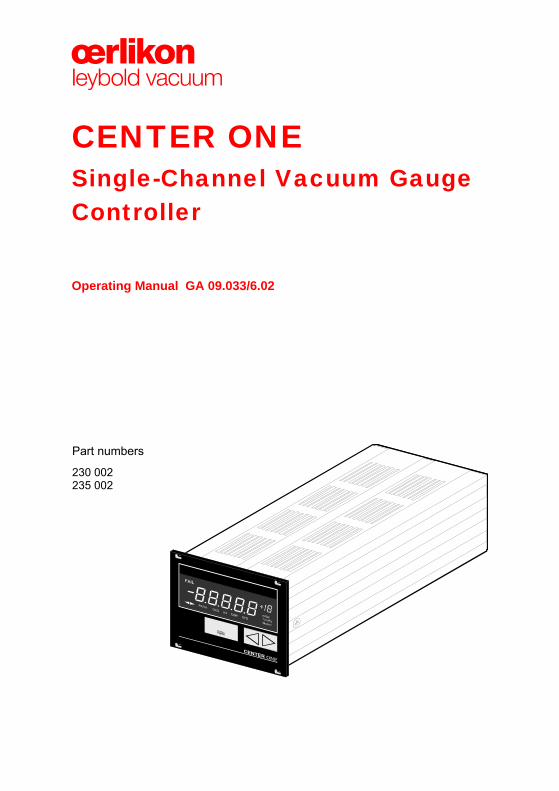
CENTER ONE Single-Channel Vacuum Gauge Controller
Operating Manual GA 09.033/6.02
Part numbers
230 002 235 002
General Information
2 GA 09.033/6.02 – (2011-07) – © Oerlikon Leybold Vacuum
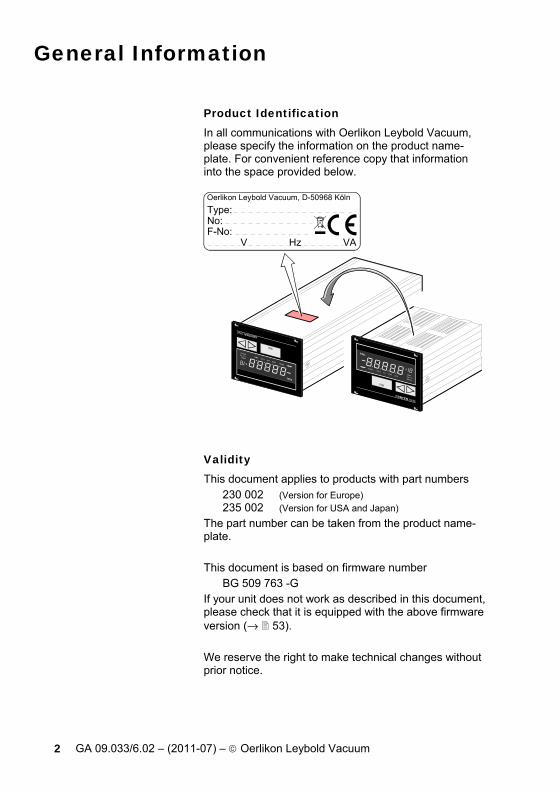
Product Identification In all communications with Oerlikon Leybold Vacuum, please specify the information on the product name-plate. For convenient reference copy that information into the space provided below.
Oerlikon Leybold Vacuum, D-50968 KölnType:No: F-No: V Hz VA
Validity This document applies to products with part numbers
230 002 (Version for Europe) 235 002 (Version for USA and Japan)
The part number can be taken from the product name-plate. This document is based on firmware number
BG 509 763 -G If your unit does not work as described in this document, please check that it is equipped with the above firmware version (→ 53). We reserve the right to make technical changes without prior notice.
General Information
GA 09.033/6.02 – (2011-07) – © Oerlikon Leybold Vacuum 3
Intended Use CENTER ONE is used together with Leybold Vakuum Transmitters (in this document referred to as gauges) for total pressure measurement. All products must be operated in accordance with the relevant operating instructions.
Trademarks
THERMOVAC®, PENNINGVAC®
CERAVAC®, IONIVAC® ⎫⎬⎭
Oerlikon Leybold Vacuum

Contents
4 GA 09.033/6.02 – (2011-07) – © Oerlikon Leybold Vacuum
Product Identification 2 Validity 2 Intended Use 3 Trademarks 3 1 Safety 6 1.1 Symbols Used 6 1.2 Personnel Qualifications 6 1.3 General Safety Instructions 6 1.4 Liability and Warranty 8 2 Technical Data 9 3 Installation 14 3.1 Personal 14 3.2 Installation, Setup 14 3.2.1 Rack Installation 14 3.2.2 Installation in a Control Panel 20 3.2.3 Use as Desk-Top Unit 21 3.3 Mains Power Connector 22 3.4 SENSOR Connector 23 3.5 Interface Connector RS232 25 3.6 CONTROL Connector 26 4 Operation 27 4.1 Front Panel 27 4.2 Turning CENTER ONE On and Off 29 4.3 Operating Modes 30 4.4 Measurement Mode 30 4.4.1 Operation 31 4.4.2 Turning the Gauge On/Off 32 4.4.3 Gauge Identification 33 4.5 Parameter Mode 34 4.5.1 Operation 35 4.5.2 Parameters 37 4.6 Test Mode 51 4.6.1 Operation 52 4.6.2 Parameters 53 4.6.3 Test Programs 55 5 Communication (Serial Interface) 61 5.1 RS232C Interface 61 5.1.1 Data Transmission 61 5.1.2 Communication Protocol 63 5.2 Mnemonics 65 5.2.1 Measurement Mode 66 5.2.2 Parameter Mode 70 5.2.3 Test Mode 77 5.2.4 Example 82
Contents
GA 09.033/6.02 – (2011-07) – © Oerlikon Leybold Vacuum 5
6 Maintenance 83 7 Troubleshooting 84 8 Accessories 86 9 Storage 86 10 Disposal 87 Appendix 88 A: Conversion Tables 88 B: Default Parameters 89 C: Firmware Update 90 D: Literature 93 E: Index 96 EC Declaration of Conformity 96 For cross-references within this document, the symbol (→ XY) is used, for cross-references to other docu-ments, the symbol (→ [Z]).

Safety
6 GA 09.033/6.02 – (2011-07) – © Oerlikon Leybold Vacuum
1 Safety
1.1 Symbols Used
DANGER
Information on preventing any kind of physical injury.
WARNING
Information on preventing extensive equipment and environmental damage.
Caution
Information on correct handling or use. Disregard can lead to malfunctions or minor equipment damage.
1.2 Personnel Qualifications
Skilled personnel
All work described in this document may only be car-ried out by persons who have suitable technical train-ing and the necessary experience or who have been instructed by the end-user of the product.
1.3 General Safety Instructions
• Adhere to the applicable regulations and take the necessary precautions for all work you are going to do and consider the safety instructions in this docu-ment.
Communicate the safety instructions to all other users.
Safety
GA 09.033/6.02 – (2011-07) – © Oerlikon Leybold Vacuum 7
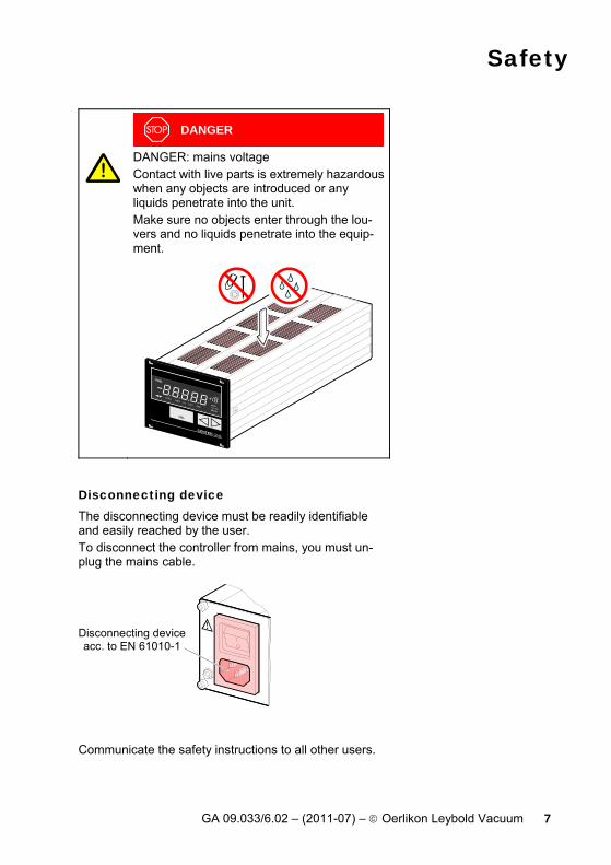
DANGER
DANGER: mains voltage Contact with live parts is extremely hazardous when any objects are introduced or any liquids penetrate into the unit. Make sure no objects enter through the lou-vers and no liquids penetrate into the equip-ment.
Disconnecting device The disconnecting device must be readily identifiable and easily reached by the user. To disconnect the controller from mains, you must un-plug the mains cable.
Disconnecting deviceacc. to EN 61010-1
Communicate the safety instructions to all other users.

Safety
8 GA 09.033/6.02 – (2011-07) – © Oerlikon Leybold Vacuum
1.4 Liability and Warranty Oerlikon Leybold Vacuum assumes no liability and the warranty becomes null and void if the end-user or third parties • disregard the information in this document • use the product in a non-conforming manner • make any kind of interventions (modifications, altera-
tions etc.) on the product • use the product with accessories not listed in the cor-
responding documentation.
Technical Data
GA 09.033/6.02 – (2011-07) – © Oerlikon Leybold Vacuum 9
2 Technical Data
Mains specifications Voltage 85 … 264 V∼ Frequency 50 … 60 Hz Power consumption ≤30 W Overvoltage category II Protection class 1 Connection European appliance connec-
tor IEC 320 C14
Ambiance Temperature
storage operation
–20 … +60 °C + 5 … +50 °C
Relative humidity ≤80% up to +31 °C, decreasing to 50% at +40 °C
Use indoors only max. altitude 2000 m NN
Pollution degree II Protection type IP30
Compatible gauges Number 1 Compatible types
Pirani Pirani/Capacitive Cold cathode Cold cathode/Pirani Capacitive Ionization Ionization/Pirani
TTR 90, TTR 211S, TTR 91, TTR 91 S, TTR 96 S TTR 100, TTR 100 S2, TTR 101, TTR 101 S2 PTR 225 PTR 90 CTR 90, CTR 91, CTR 100, CTR 101, DI 200, DI 201, DI 2000, DI 2001, DI 2001 relITR 90 ITR 100, ITR 200
Technical Data
10 GA 09.033/6.02 – (2011-07) – © Oerlikon Leybold Vacuum
Gauge connection Number 2 (parallel)
Caution
Do not connect more than one gauge at the same time.
Connector 15-pin D-Sub, female, RJ45 (FCC68) (pin assignment → 24)
Operation Manual HOST
via 3 keys via RS232C interface
Measurement values Measurement ranges depending on gauge
(→ [1] … [16]) Measurement error
gain error offset error
≤0.02% FSr ≤0.05% FSr
Measurement rate analog digital
100 / s 50 / s (CTR 100, CTR 101, ITR 90, ITR 200) 10 / s (ITR 100)
Display rate 10 / s Filter time constant
slow normal (nor) fast
750 ms (fg = 0.2 Hz) 150 ms (fg = 1 Hz) 20 ms (fg = 8 Hz)
Measurement units mbar, Pa, Torr, Micron Zero adjust for linear gauges Correction factor for logarithmic gauges
0.10…10.00 A/D converter resolution >0.001% FSr
(The measurement values of ITR, CTR 100 and CTR 101 are transmitted digitally.)

Technical Data
GA 09.033/6.02 – (2011-07) – © Oerlikon Leybold Vacuum 11
Gauge supply Voltage +24 V= ±5% Current 750 mA Fuse protection 900 mA with PTC element,
self-resetting after turning CENTER ONE off or discon-necting the gauge
Switching function Number 1 Reaction delay ≤10 ms if switching threshold
close to measurement value (for larger differences con-sider filter time constant)
Adjustment range depending on gauge (→ [1] … [16])
Hysteresis ≥1% FSr for linear gauges ≥10% of measurement value for logarithmic gauges
Switching function relay Contact type floating changeover contact Load max. 125 V∼, 60 W (ohmic)
110 V=, 2 A, 60 W (ohmic)
DANGER
For benchtop use, max. 30 V~ or 60 V= may be connected.
Service life mechanic electric
108 105 (at maximum load)
Connector 9-pin D-Sub, male (pin assignment → 26)
Contact positions
234
Vacuum pressure lower than switching threshold
234
Vacuum pressure higher than switch-ing threshold or no mains power

Technical Data
12 GA 09.033/6.02 – (2011-07) – © Oerlikon Leybold Vacuum
Error signal (Error) Number 1 Reaction time ≤20 ms
Error signal relay Contact type floating normally open contact Load max. 125 V∼, 60 W (ohmic)
110 V=, 2 A, 60 W (ohmic)
DANGER
For benchtop use, max. 30 V~ or 60 V= may be connected.
Service life mechanic electric
108 105 (at maximum load)
Connector 9-pin D-Sub, male (pin assignment → 26)
Contact positions 98
no error
98
error or no mains power
Analog output Number 1, recorder output Voltage range 0 … +10 V Deviation from displayed value
±50 mV
Internal resistance 660 Ω Relationship measurement signal- pressure
depending on gauge (→ [1] … [16])
Connector 9-pin D-Sub, male (pin assignment → 26)

Technical Data
GA 09.033/6.02 – (2011-07) – © Oerlikon Leybold Vacuum 13
HOST interface Standard RS232C Protocol ACK/NAK, ASCII with
3-character mnemonics, bi-directional data flow
RS232C only TXD and RXD used Transmission rate 9600, 19200, 38400 baud Connector 9-pin D-Sub, female
(pin assignment → 25)
Dimensions [mm]
91.2 ø3.5
106.2
78 84
204.5 2.5285
A
67.3
103.6
View A
Use For incorporation into a rack or control panel or for use as desk-top unit.
Weight 0.85 kg
Installation
14 GA 09.033/6.02 – (2011-07) – © Oerlikon Leybold Vacuum
3 Installation
3.1 Personal
Skilled personnel
The unit may only be installed by persons who have suitable technical training and the necessary experience.
3.2 Installation, Setup CENTER ONE is suited for incorporation into a 19" rack or a control panel or for use as desk-top unit.
DANGER
DANGER: damaged product Putting a damaged product into operation can be extremely hazardous. In case of visible damage make sure the product is not put into operation.
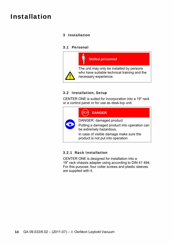
3.2.1 Rack Installation CENTER ONE is designed for installation into a 19" rack chassis adapter using according to DIN 41 494. For this purpose, four collar screws and plastic sleeves are supplied with it.

Installation
GA 09.033/6.02 – (2011-07) – © Oerlikon Leybold Vacuum 15
DANGER
DANGER: protection class of the rack If the product is installed in a rack, it is likely to lower the protection class of the rack (pro-tection against foreign bodies and water) e.g. the EN 60204-1 regulations for switch cabinets. Take appropriate measures for the rack to meet the specifications of the protection class.
Guide rail In order to reduce the mechanical strain on the front panel of CENTER ONE, preferably equip the rack chas-sis adapter with a guide rail.

Installation
16 GA 09.033/6.02 – (2011-07) – © Oerlikon Leybold Vacuum
Slide rails For safe and easy installation of heavy rack chassis adapters, preferably equip the rack frame with slide rails.
Installation
GA 09.033/6.02 – (2011-07) – © Oerlikon Leybold Vacuum 17
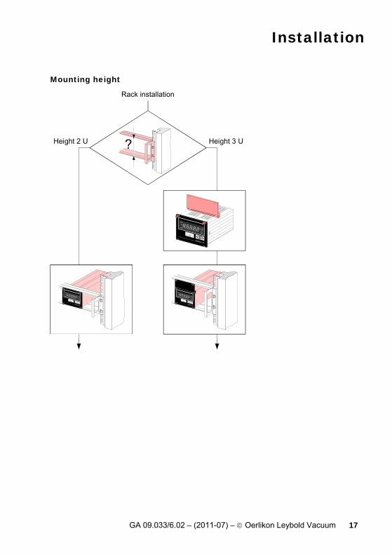
Mounting height
Height 3 UHeight 2 U
Rack installation

Installation
18 GA 09.033/6.02 – (2011-07) – © Oerlikon Leybold Vacuum
Height 2 U rack chassis adapter
Secure the rack chassis adapter in the rack frame.
Slide CENTER ONE into the adapter.
Height 2 U
Fasten CENTER ONE to the rack chassis adapter using the screws supplied with it.
The temperature inside the switching cabinet must not exceed the admissible maximum am-bient temperature (→ 9).
Height 3 U rack chassis adapter For incorporation into a 19" rack chassis adapter, heigth 3, an adapter panel (incl. two collar screws and plastic sleeves) is available (→ 86).
Secure the rack adapter in the rack frame.
Installation
GA 09.033/6.02 – (2011-07) – © Oerlikon Leybold Vacuum 19
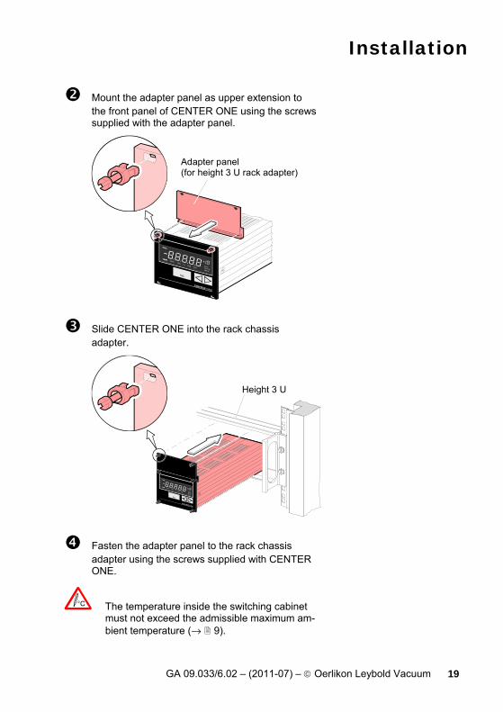
Mount the adapter panel as upper extension to the front panel of CENTER ONE using the screws supplied with the adapter panel.
Adapter panel(for height 3 U rack adapter)
Slide CENTER ONE into the rack chassis adapter.
Height 3 U
Fasten the adapter panel to the rack chassis adapter using the screws supplied with CENTER ONE.
The temperature inside the switching cabinet must not exceed the admissible maximum am-bient temperature (→ 9).

Installation
20 GA 09.033/6.02 – (2011-07) – © Oerlikon Leybold Vacuum
3.2.2 Installation in a Control Panel For mounting CENTER ONE into a control panel, the following cut-out is required:
M3 or ø 3.5
10591.2
78 69
For reducing the mechanical strain on the front panel, preferably support the unit.
Slide CENTER ONE into the cut-out of the control panel.
Secure it with four M3 screws.
Make sure the admissible maximum ambient temperature (→ 9) is not exceeded.
Installation
GA 09.033/6.02 – (2011-07) – © Oerlikon Leybold Vacuum 21
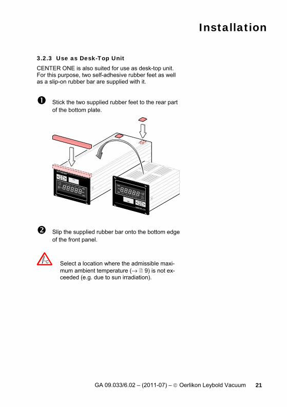
3.2.3 Use as Desk-Top Unit CENTER ONE is also suited for use as desk-top unit. For this purpose, two self-adhesive rubber feet as well as a slip-on rubber bar are supplied with it.
Stick the two supplied rubber feet to the rear part of the bottom plate.
Slip the supplied rubber bar onto the bottom edge of the front panel.
Select a location where the admissible maxi-mum ambient temperature (→ 9) is not ex-ceeded (e.g. due to sun irradiation).
Installation
22 GA 09.033/6.02 – (2011-07) – © Oerlikon Leybold Vacuum
3.3 Mains Power Connector
DANGER
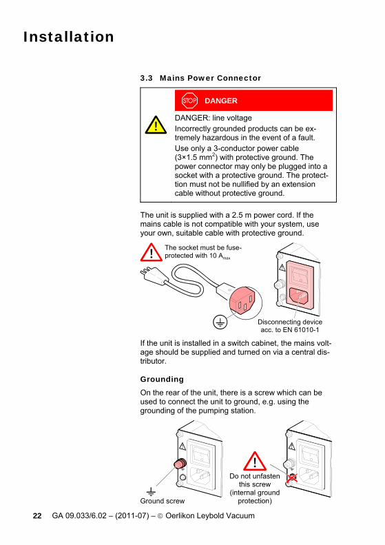
DANGER: line voltage Incorrectly grounded products can be ex-tremely hazardous in the event of a fault. Use only a 3-conductor power cable (3×1.5 mm2) with protective ground. The power connector may only be plugged into a socket with a protective ground. The protect-tion must not be nullified by an extension cable without protective ground.
The unit is supplied with a 2.5 m power cord. If the mains cable is not compatible with your system, use your own, suitable cable with protective ground.
The socket must be fuse-protected with 10 Amax
Disconnecting deviceacc. to EN 61010-1
If the unit is installed in a switch cabinet, the mains volt-age should be supplied and turned on via a central dis-tributor.
Grounding On the rear of the unit, there is a screw which can be used to connect the unit to ground, e.g. using the grounding of the pumping station.
Do not unfastenthis screw
(internal groundprotection)Ground screw

Installation
GA 09.033/6.02 – (2011-07) – © Oerlikon Leybold Vacuum 23
3.4 SENSOR Connector CENTER ONE is equipped with two different gauge connectors.
Caution
Caution: one channel measurement unit Connecting more than one gauge at the same time may lead to gauge destruction.
1 only at once Make sure that there is never more than one gauge connected to CENTER ONE at the same time.
Connect the gauge to one of the two SENSOR connec-tors on the rear of the unit. Use a screened 1:1 cable (electromagnetic compatibility). Make sure the gauge is compatible (→ 9).
DANGER
DANGER: protective low voltage According to EN 61010, voltages exceeding 30 VAC or 60 VDC are hazardous. If you are using the CENTER ONE as desk-top unit, you may only connect a protective low voltage (SELV).

Installation
24 GA 09.033/6.02 – (2011-07) – © Oerlikon Leybold Vacuum
The transmission rate of the ITR 100 ionization vacuum gauge must be set to 9600 baud (→ [11]).
Pin assignment Pin assignment of the 8-pin RJ45 appliance connector:
Socket Signal
1 2 3 4 5 6 7 8
+24 V= PGND Signal Ident Signal GND Status HV_L HV_H
Pin assignment of the 15-pin D-Sub appliance connector:
Socket Signal 1 2 3 4 5 6 7 8 9 10 11 12 13 14 15
Emi status Signal Status HV_H PGND Not used Degas Supply_ITR Not used Ident Supply_CTR Signal-GND RXD TXD Chassis
Installation
GA 09.033/6.02 – (2011-07) – © Oerlikon Leybold Vacuum 25
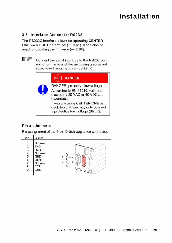
3.5 Interface Connector RS232 The RS232C interface allows for operating CENTER ONE via a HOST or terminal (→ 61). It can also be used for updating the firmware (→ 90).
Connect the serial interface to the RS232 con-nector on the rear of the unit using a screened cable (electromagnetic compatibility).
DANGER
DANGER: protective low voltage According to EN 61010, voltages exceeding 30 VAC or 60 VDC are hazardous. If you are using CENTER ONE as desk-top unit you may only connect a protective low voltage (SELV).
Pin assignment Pin assignment of the 9-pin D-Sub appliance connector:
Pin Signal 1 2 3 4 5 6 7 8 9
Not used TXD RXD Not used GND DSR Not used CTS GND

Installation
26 GA 09.033/6.02 – (2011-07) – © Oerlikon Leybold Vacuum
3.6 CONTROL Connector This connector allows to read the measurement signal, to evaluate state of the floating switching function and error contacts, and to activate/deactivate the high vac-uum measurement circuit (only for PTR 225 cold cath-ode gauge and ITR 100 ionization vacuum gauge).
Operation via the CONTROL connector (input HV_H, → 26) has priority over key operation.
DANGER
DANGER: protective low voltage According to EN 61010, voltages exceeding 30 VAC or 60 VDC are hazardous. If you are using CENTER ONE as desk-top unit you may only connect a protective low voltage (SELV).
Connect the peripheral components to the CONTROL connector on the rear of the unit. Use a screened cable (electromagnetic com-patibility).
Pin assignment Pin assignment of the 9-pin D-Sub appliance connector:
Pin Signal 1 2
3
4
5
6 7 8 9
Analog output Switching function off (n.c. contact) Switching function (common) Switching function off (n.o. contact) Control input HV_H On = +24 V Off = 0 V +24 V Chassis Error (n.o. contact) Error (common)
The analog output (pin 1) differ from the displayed value by no more than ±50 mV.
Operation
GA 09.033/6.02 – (2011-07) – © Oerlikon Leybold Vacuum 27
4 Operation
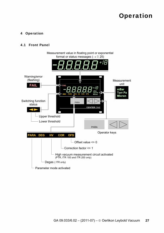
4.1 Front Panel
Operator keys
Measurementunit
Switching functionstatus
Upper threshold
Lower threshold
Measurement value in floating point or exponentialformat or status messages (→ 25)
Warning/error(flashing)
Offset value <> 0
Correction factor <> 1
High vacuum measurement circuit activated(PTR, ITR 100 and ITR 200 only)
Degas ( ITR only)
Parameter mode activated

Operation
28 GA 09.033/6.02 – (2011-07) – © Oerlikon Leybold Vacuum
Status messages If there are any status messages pending, they are dis-played instead of the measurement vale.
Gauge cannot be identified or e.g. line break (sensor error). The
lamp flashes.
The measurement value is above the upper measurement range limit of the connected gauge. The
lamp flashes.
The measurement value is below the lower measurement range limit of the connected gauge. The
lamp flashes.
Parameter setup lock activated (→ 54).
Error messages ITR 90 and ITR 100
Meaning → [10], [11]
ITR 90: 0…9 ITR 100: 1…6
0 = no communication to the transmitter 1…9 = High-Byte of Error-Byte
Error messages ITR 200
x x
Meaning → [13] xx = Error-Byte (HEX)

Operation
GA 09.033/6.02 – (2011-07) – © Oerlikon Leybold Vacuum 29
4.2 Turning CENTER ONE On and Off Make sure CENTER ONE is correctly installed and the specifications in the Technical Data are met.
Turning CENTER ONE on The power switch is on the rear of the unit. Turn CENTER ONE on with the power switch (or centrally, via a switched power distributor, if the unit is incorporated in a rack).
After power ON, CENTER ONE … • automatically performs a self-test • identifies the connected gauge • activates the parameters that were in effect before
the last power OFF • switches to the Measurement mode • adapts the parameters if required (if another gauge
was previously connected).
Turning CENTER ONE off Turn CENTER ONE off with the power switch (or cen-trally, via a switched power distributor, if the unit is in-corporated in a rack).
Wait at least 10 s before turning CENTER ONE on again in order for it to correctly initialize it-self.

Operation
30 GA 09.033/6.02 – (2011-07) – © Oerlikon Leybold Vacuum
4.3 Operating Modes CENTER ONE works in the following operating modes: • Measurement mode
for displaying measurement values or statuses (→ 30)
• Parameter mode for entering or displaying parameters (→ 34)
• Test mode for running internal test programs (→ 51)
• Program transfer mode for updating the firmware (→ 90)
4.4 Measurement Mode The Measurement mode is the standard operating mode of CENTER ONE. Measurement values and statuses as well as the gauge identification are displayed in this mode. To get to the Measurement mode, … • turn CENTER ONE on • do not press any key for at least 10 s while you are in
the Parameter mode • press the "PARA" key after Parameter X ("bAud"),
while you are in the Parameter mode • press all three keys simultaneously for at least 5 s
while you are in the Test mode.
To quit the Measurement mode, … • turn CENTER ONE off • press the "PARA" key (to get to the Parameter mode) • press all three keys simultaneously for at least 5 s (to
get to the Test mode).
Operation
GA 09.033/6.02 – (2011-07) – © Oerlikon Leybold Vacuum 31
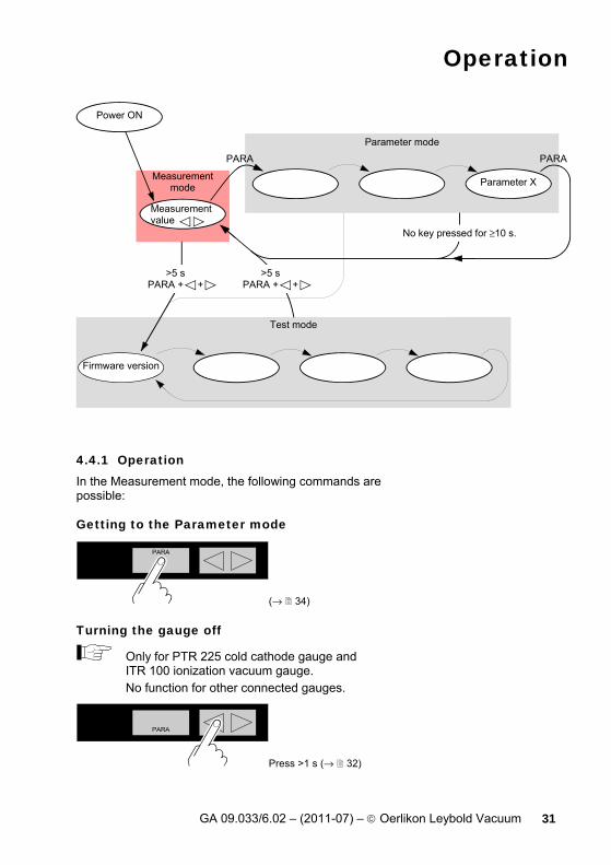
Parameter mode
Measurementmode
Test mode
Firmware version
No key pressed for ≥10 s.
PARAPARA
Measurementvalue
Parameter X
Power ON
>5 sPARA + +
>5 sPARA + +
4.4.1 Operation In the Measurement mode, the following commands are possible:
Getting to the Parameter mode
(→ 34)
Turning the gauge off
Only for PTR 225 cold cathode gauge and ITR 100 ionization vacuum gauge. No function for other connected gauges.
Press >1 s (→ 32)
Operation
32 GA 09.033/6.02 – (2011-07) – © Oerlikon Leybold Vacuum
Turning the gauge on
Only for PTR 225 cold cathode gauge and ITR 100 ionization vacuum gauge. No function for other connected gauges.
Press >1 s (→ 32)
Displaying the gauge identification
Press >0.5 s (→ 33)
Getting to the Test mode
Press >5 s (→ 51)
4.4.2 Turning the Gauge On/Off Only for PTR 225 cold cathode gauge and ITR 100
ionization vacuum gauge. The high vacuum measurement circuit of these gauges can be activated in both, the Measurement and the Pa-rameter mode (→ 48).
The current setting is displayed:
High vacuum measurement circuit activated
High vacuum measurement circuit deactivated
Operation
GA 09.033/6.02 – (2011-07) – © Oerlikon Leybold Vacuum 33
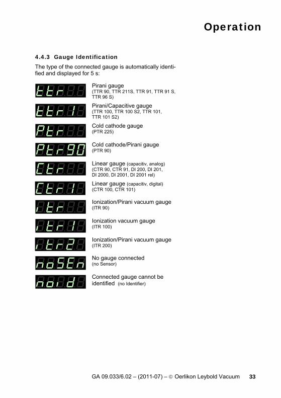
4.4.3 Gauge Identification The type of the connected gauge is automatically identi-fied and displayed for 5 s:
Pirani gauge (TTR 90, TTR 211S, TTR 91, TTR 91 S, TTR 96 S)
Pirani/Capacitive gauge (TTR 100, TTR 100 S2, TTR 101, TTR 101 S2)
Cold cathode gauge (PTR 225)
Cold cathode/Pirani gauge (PTR 90)
Linear gauge (capacitiv, analog) (CTR 90, CTR 91, DI 200, DI 201, DI 2000, DI 2001, DI 2001 rel)
Linear gauge (capacitiv, digital) (CTR 100, CTR 101)
Ionization/Pirani vacuum gauge (ITR 90)
Ionization vacuum gauge (ITR 100)
Ionization/Pirani vacuum gauge (ITR 200)
No gauge connected (no Sensor)
Connected gauge cannot be identified (no Identifier)

Operation
34 GA 09.033/6.02 – (2011-07) – © Oerlikon Leybold Vacuum
4.5 Parameter Mode The Parameter mode is used for displaying, modifying and entering parameter values. To get to the Parameter mode, … • press the "PARA" key while you are in the Measure-
ment mode.
To quit the Parameter mode, … • turn CENTER ONE off • do not press any key for at least 10 s • press the "PARA" key after Parameter X ("bAud"), (to
get to the Measurement mode) • press all three keys simultaneously for at least 5 s (to
get to the Test mode).
Parameter
Parameter 2 Parameter X
Measurementmode
Parameter 1
PARA PARA PARAPARA
Measurementvalue
Wait ≥10 s without pressing any key.
Power ON

Operation
GA 09.033/6.02 – (2011-07) – © Oerlikon Leybold Vacuum 35
4.5.1 Operation In the Parameter mode, the following commands are possible:
Selecting a parameter
The name of the parameter is displayed as long as the key is pressed or at least for 2 s.
Degas function (→ 38) Lower switching threshold (→ 38) Upper switching threshold (→ 38) Measurement range of linear gauges (→ 42) Offset correction / zero adjust of linear gauges (→ 43) Measurement unit (→ 45) Correction factor (→ 45) Filter time constant (→ 46) High vacuum measurement circuit (→ 48) Transmission rate of the interface (→ 49) Emission (→ 49) Filament (→ 49)
Modifying a parameter
│ Press <1 s >1 s
The value is de-creased in small increments
The value is de-creased in large increments
The parameter value is modified by 1 increment.
Operation
36 GA 09.033/6.02 – (2011-07) – © Oerlikon Leybold Vacuum
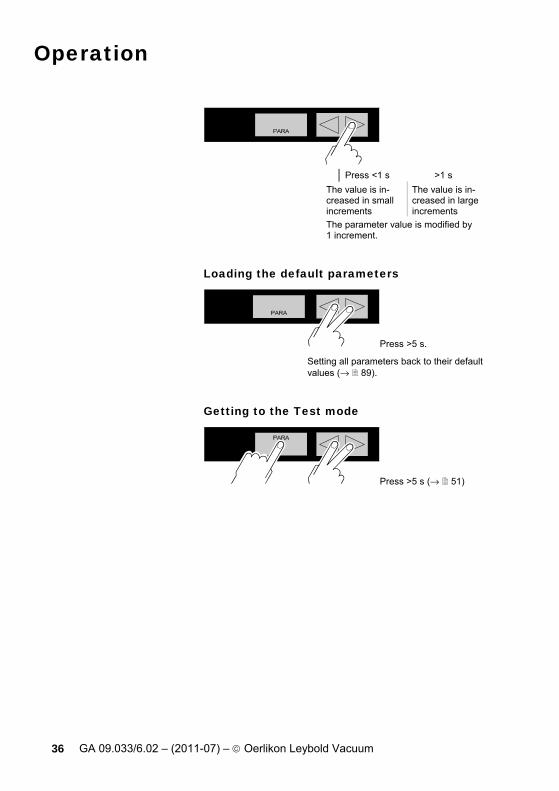
│ Press <1 s >1 s
The value is in-creased in small increments
The value is in-creased in large increments
The parameter value is modified by 1 increment.
Loading the default parameters
Press >5 s. Setting all parameters back to their default values (→ 89).
Getting to the Test mode
Press >5 s (→ 51)

Operation
GA 09.033/6.02 – (2011-07) – © Oerlikon Leybold Vacuum 37
4.5.2 Parameters Some parameters are not available for all gauge types. They are only displayed if available. The following table shows which parameters are available for which gauges.
Operation
38 GA 09.033/6.02 – (2011-07) – © Oerlikon Leybold Vacuum
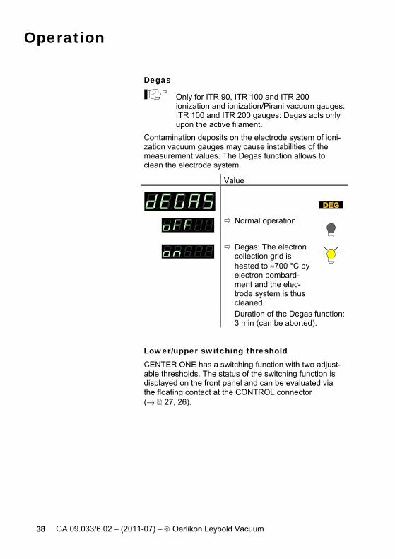
Degas
Only for ITR 90, ITR 100 and ITR 200 ionization and ionization/Pirani vacuum gauges. ITR 100 and ITR 200 gauges: Degas acts only upon the active filament.
Contamination deposits on the electrode system of ioni-zation vacuum gauges may cause instabilities of the measurement values. The Degas function allows to clean the electrode system.
Value
Normal operation.
Degas: The electron collection grid is heated to ≈700 °C by electron bombard-ment and the elec-trode system is thus cleaned.
Duration of the Degas function: 3 min (can be aborted).
Lower/upper switching threshold CENTER ONE has a switching function with two adjust-able thresholds. The status of the switching function is displayed on the front panel and can be evaluated via the floating contact at the CONTROL connector (→ 27, 26).
Operation
GA 09.033/6.02 – (2011-07) – © Oerlikon Leybold Vacuum 39
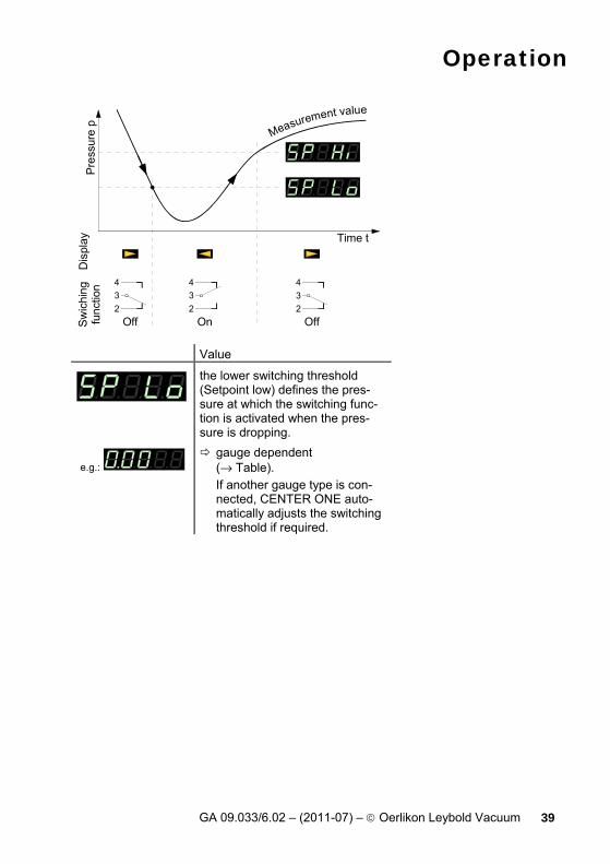
Pres
sure
pSw
ichi
ngfu
nctio
n
On Off
Time t
Off234
234
234
Dis
play
Measurement value
Value
the lower switching threshold (Setpoint low) defines the pres-sure at which the switching func-tion is activated when the pres-sure is dropping.
e.g.: gauge dependent (→ Table). If another gauge type is con-nected, CENTER ONE auto-matically adjusts the switching threshold if required.

Operation
40 GA 09.033/6.02 – (2011-07) – © Oerlikon Leybold Vacuum
FSrFSr / 1000
1×1031×10-8
FSr / 1000
5×10²
1×10⁻²
2×10⁻³ *)
1×10⁻⁹
1×10⁻¹⁰ 1×10⁻¹
1×1031×10-8
1.5×1032×10-3 *)
5×10⁻⁹ 1×10³
FSrlo
wer
thre
shol
dlim
it
uppe
rth
resh
old
limit
all values in mbar *) 2×10⁻⁴ mbar if PrE is activated (→ 50)
The minimum hysteresis between the upper and lower switching threshold is at least 10% of the lower threshold or 1% of the set full scale value. If the value of the minimum hysteresis drops below these values, the upper threshold is automatically adjusted. This prevents unsta-ble states.

Operation
GA 09.033/6.02 – (2011-07) – © Oerlikon Leybold Vacuum 41
Value
the upper switching threshold (Setpoint high) defines the pres-sure at which the switching func-tion is deactivated when the pres-sure is rising.
e.g.: gauge dependent (→ Table). If another gauge type is con-nected, CENTER ONE auto-matically adjusts the threshold if required.
unte
rer S
chw
ellw
ert
5×10²
1×10⁻²
FSr
1×10³
1×10⁻¹
1.5E3
1×10⁻³
FSr
1×10³
low
erth
resh
old
limit
uppe
rth
resh
old
limit
+10% lower threshold
+10% lower threshold
+10% lower threshold
+10% lower threshold
+1% measurement range(FSr)
+10% lower threshold
+10% lower threshold
+10% lower threshold
+1% measurement range(FSr)
The minimum hysteresis between the upper and lower switching threshold is at least 10% of the lower threshold or 1% of the set full scale value. This prevents unstable states.

Operation
42 GA 09.033/6.02 – (2011-07) – © Oerlikon Leybold Vacuum
Measurement range (F.S.) of capacitive gauges
Only for CTR 90, CTR 91 CTR 100, CTR 101, DI 200, DI 201, DI 2000, DI 2001 and DI 2001 rel linear gauges.
The full scale value of the measurement range (Full Scale) of the linear gauges has to be defined by the user; the full scale value of logarithmic gauges is auto-matically recognized.
Value
e.g.: 0.01 mbar
0.01 Torr, 0.02 Torr, 0.05 Torr
0.10 mbar, 0.25 mbar, 0.50 mbar 0.10 Torr, 0.25 Torr, 0.50 Torr
1 mbar, 2 mbar, 5 mbar 1 Torr, 2 Torr, 5 Torr
10 mbar, 20 mbar, 50 mbar 10 Torr, 20 Torr, 50 Torr
100 mbar, 200 mbar, 500 mbar 100 Torr, 200 Torr, 500 Torr
1000 mbar, 1100 mbar 1000 Torr
2 bar, 5 bar, 10 bar, 50 bar
DI-Messköpfe: di200 200 mbar di2 2 bar dir2 2 bar relativ
Conversion table → Appendix 88.
Operation
GA 09.033/6.02 – (2011-07) – © Oerlikon Leybold Vacuum 43
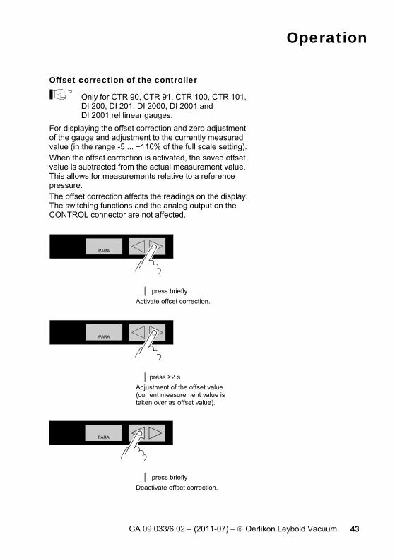
Offset correction of the controller
Only for CTR 90, CTR 91, CTR 100, CTR 101, DI 200, DI 201, DI 2000, DI 2001 and DI 2001 rel linear gauges.
For displaying the offset correction and zero adjustment of the gauge and adjustment to the currently measured value (in the range -5 ... +110% of the full scale setting). When the offset correction is activated, the saved offset value is subtracted from the actual measurement value. This allows for measurements relative to a reference pressure. The offset correction affects the readings on the display. The switching functions and the analog output on the CONTROL connector are not affected.
│ press briefly Activate offset correction.
│ press >2 s Adjustment of the offset value (current measurement value is taken over as offset value).
│ press briefly Deactivate offset correction.

Operation
44 GA 09.033/6.02 – (2011-07) – © Oerlikon Leybold Vacuum
Value
Offset correction deactivated
e.g.: Offset correction activated
Zero adjustment of the gauge
Only for CTR 100 and CTR 101 linear gauges with Type C connection cable.
First adjust the gauge and then the controller.
Deactivate the offset correction before adjusting the zero of the gauge you are using (→ 43).
│ press >2 s Zero adjustment only for CTR 100 and CTR 101.
Value
e.g.: Zero adjustment activated
Lit solid after >2 s andas long as key remains pressed
After adjusting the zero point, a zero value is displayed. Due to the measuring resolution of the CTR 100 and CTR 101 (noise, drift), a zero with plus/minus several digits are displayed.

Operation
GA 09.033/6.02 – (2011-07) – © Oerlikon Leybold Vacuum 45
Measurement unit Measurement unit of the measurement value, switching threshold value, etc. → Appendix 88 for Conversion table.
This parameter setting is also effective for ITR 90 and ITR 200 gauges.
Value
mbar/bar
Torr (only available if Torr lock disabled → 54)
Pascal
Micron (=mTorr)
When selecting Micron, above 99000 Micron the readout automatically changes over to Torr. When the pressure drops below 90 Torr the instrument automatically switches back to Micron.
Correction factor
Not for CTR 90, CTR 91, CTR 100, CTR 101, DI 200, DI 201, DI 2000, DI 2001 and DI 2001 rel linear gauges. For ITR 90 and ITR 200 Ionization/Pirani vacuum gauges only for pressures <1×10⁻² mbar. For Pirani/Capacitive gauges TTR 100, TTR 100 S2, TTR 101 and TTR 101 S2 only for pressures <10 mbar.
The correction factor allows to convert the measurement value for other gases than N2 (→ Characteristic curves in [1], [2], [3], [5], [10], [13]).

Operation
46 GA 09.033/6.02 – (2011-07) – © Oerlikon Leybold Vacuum
Value
e.g.: no correction
e.g.: Measurement value corrected by a factor of 0.10 … 10.00
Measurement value filter The measurement value filter permits a better evaluation of unstable or disturbed measurement signals.
The measurement value filter affects neither the analog output (→ 26) nor the digitally transmitted measurement value of the ITR 90, ITR 100 and ITR 200 Ionization and Ionization/ Pirani vacuum gauges.
Value
fast: CENTER ONE responds quickly to fluctuations of the measurement value. As a con-sequence, it will also respond faster to interferences in measured values.

Operation
GA 09.033/6.02 – (2011-07) – © Oerlikon Leybold Vacuum 47
normal: Good relationship between re-sponse and sensitivity of the display and the switching func-tions to changes in the meas-ured values.
slow: CENTER ONE does not re-spond to small changes in measured values. As a conse-quence, it will also respond more slowly to changes in the measured values.
For CTR gauges only. The response of the CENTER ONE to signal changes depends on the measuring range. The dis-play is especially stable in the low measuring range.
Measuring range Filter FS … 0.1 FS nor (normal) 0.1 FS … 0.04 FS SLo (slow) 0.04 FS … 0.01 FS ≈2.5 × SLo 0.01 FS … 0 ≈5 × SLo

Operation
48 GA 09.033/6.02 – (2011-07) – © Oerlikon Leybold Vacuum
Turning the gauge on/off
Only for PTR 225 cold cathode gauge and ITR 100 ionization vacuum gauge.
Activating/deactivating the high vacuum measurement circuit (→ also 32).
Value
High vacuum meas-urement circuit acti-vated
High vacuum meas-urement circuit de-activated
Display resolution (digits) Display resolution of measured values.
Value
Display • rounded to one
decimal digit • or two integrals
Display • rounded to two
decimal digits • or three inte-
grals
When the PrE (→ 50) is ON and the pressure is in the range p<1.0E-4 mbar the display resolution of the TTR transmitters is reduced by one decimal digit.
Operation
GA 09.033/6.02 – (2011-07) – © Oerlikon Leybold Vacuum 49
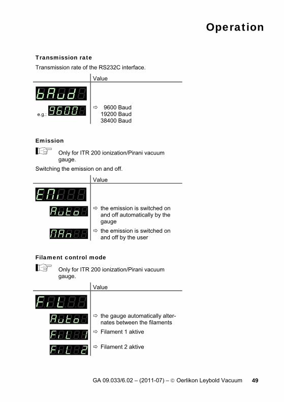
Transmission rate Transmission rate of the RS232C interface.
Value
e.g.: 9600 Baud 19200 Baud 38400 Baud
Emission
Only for ITR 200 ionization/Pirani vacuum gauge.
Switching the emission on and off.
Value
the emission is switched on and off automatically by the gauge
the emission is switched on and off by the user
Filament control mode
Only for ITR 200 ionization/Pirani vacuum gauge.
Value
the gauge automatically alter-nates between the filaments
Filament 1 aktive
Filament 2 aktive
Operation
50 GA 09.033/6.02 – (2011-07) – © Oerlikon Leybold Vacuum
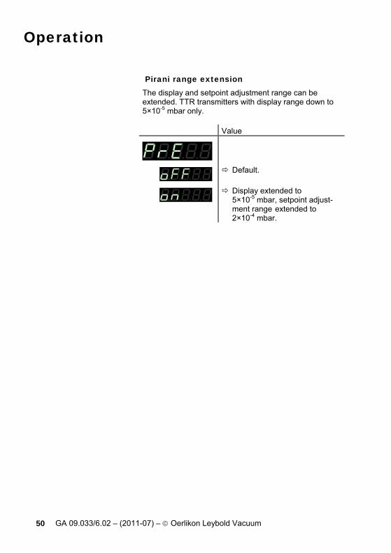
Pirani range extension The display and setpoint adjustment range can be extended. TTR transmitters with display range down to 5×10⁻⁵ mbar only. Value
Default.
Display extended to 5×10⁻⁵ mbar, setpoint adjust-ment range extended to 2×10⁻⁴ mbar.
Operation
GA 09.033/6.02 – (2011-07) – © Oerlikon Leybold Vacuum 51
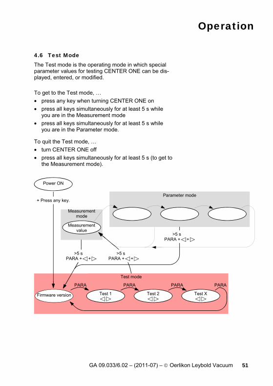
4.6 Test Mode The Test mode is the operating mode in which special parameter values for testing CENTER ONE can be dis-played, entered, or modified. To get to the Test mode, … • press any key when turning CENTER ONE on • press all keys simultaneously for at least 5 s while
you are in the Measurement mode • press all keys simultaneously for at least 5 s while
you are in the Parameter mode.
To quit the Test mode, … • turn CENTER ONE off • press all keys simultaneously for at least 5 s (to get to
the Measurement mode).
Parameter mode
Measurementmode
Measurementvalue
Power ON
Test mode
Test 2 Test XTest 1
PARA PARA
Firmware version
PARA
+ Press any key.
>5 sPARA + +
PARA
>5 sPARA + +
>5 sPARA + +
Operation
52 GA 09.033/6.02 – (2011-07) – © Oerlikon Leybold Vacuum
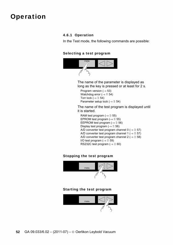
4.6.1 Operation In the Test mode, the following commands are possible:
Selecting a test program
The name of the parameter is displayed as long as the key is pressed or at least for 2 s.
Program version (→ 53) Watchdog error (→ 54) Torr lock (→ 54) Parameter setup lock (→ 54)
The name of the test program is displayed until it is started.
RAM test program (→ 55) EPROM test program (→ 55) EEPROM test program (→ 56) Display test program (→ 56) A/D converter test program channel 0 (→ 57) A/D converter test program channel 1 (→ 57) A/D converter test program channel 2 (→ 58) I/O test program (→ 59) RS232C test program (→ 60)
Stopping the test program
Starting the test program

Operation
GA 09.033/6.02 – (2011-07) – © Oerlikon Leybold Vacuum 53
Changing to the measurement mode
Press >5 s (→ 30)
4.6.2 Parameters
Firmware version The firmware version (program version) is displayed.
Version
The two parts of the firmware number are displayed alter-nately.
│ The last character indicates the modifi-cation index (-, A … Z). Please mention this index when contacting Oerlikon Leybold Vacuum in the event of a fault.

Operation
54 GA 09.033/6.02 – (2011-07) – © Oerlikon Leybold Vacuum
Watchdog error Behavior of the system control (watchdog) in the event of an error.
Setting
The system automatically ac-knowledges error messages of the watchdog after 2 s.
Error messages of the watch-dog have to be acknowledged by the operator.
Torr lock The measurement unit "Torr" can be suppressed in the corresponding parameter setting ("unit", → 45).
Setting
Lock disabled; measurement unit "Torr" available.
Lock enabled, measurement unit "Torr" not available.
Parameter setup lock This parameter affects the parameter mode. When the lock is activated, the user can inspect but not modify pa-rameter values.
Setting
Parameters can be inspected and modified.
Parameters can be inspected only.

Operation
GA 09.033/6.02 – (2011-07) – © Oerlikon Leybold Vacuum 55
4.6.3 Test Programs
RAM test Test of the main memory.
Test sequence
The test runs automatically one time:
Test in process (very briefly).
Test finished, no error found.
Test finished, error(s) found. The lamp flashes.
EPROM test Test of the program memory.
Test sequence
The test runs automatically one time:
Test in process
Test finished, no error found. After the test, a four-digit checksum (hexadecimal for-mat) is displayed.
Test finished, error(s) found. After the test, a four-digit checksum (hexadecimal for-mat) is displayed. The lamp flashes.
Operation
56 GA 09.033/6.02 – (2011-07) – © Oerlikon Leybold Vacuum
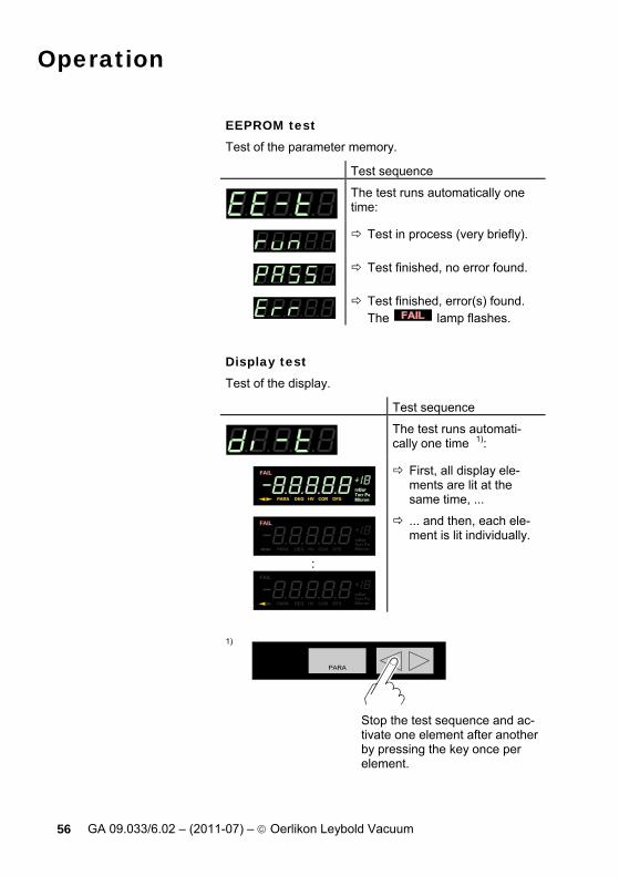
EEPROM test Test of the parameter memory.
Test sequence
The test runs automatically one time:
Test in process (very briefly).
Test finished, no error found.
Test finished, error(s) found. The lamp flashes.
Display test Test of the display.
Test sequence
The test runs automati-cally one time 1):
First, all display ele-ments are lit at the same time, ...
HV COR
:
HV COR
... and then, each ele-ment is lit individually.
1)
Stop the test sequence and ac-tivate one element after another by pressing the key once per element.

Operation
GA 09.033/6.02 – (2011-07) – © Oerlikon Leybold Vacuum 57
A/D converter test 0 Test of channel 0 of the analog/digital converter (with a reference voltage at the signal input of the SENSOR connector (→ 24)).
The measurement value filter affects the ap-plied voltage. If the signal input is open, CENTER ONE displays a default value that may easily fluctuate because of the high sensi-tivity of the open measurement circuit.
Test sequence
z.B.: Positive portion of the meas-urement signal in Volt.
A/D converter test 1 Test of channel 1 of the analog/digital converter (with a reference voltage at the signal input of the SENSOR connector (→ 24)).
The measurement value filter affects the ap-plied voltage. If the signal input is open, CENTER ONE displays a default value that may easily fluctuate because of the high sensi-tivity of the open measurement circuit.
Test sequence
z.B.: Negative portion of the meas-urement signal in Volt.
Operation
58 GA 09.033/6.02 – (2011-07) – © Oerlikon Leybold Vacuum
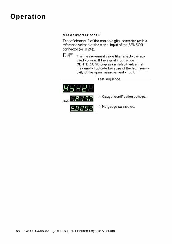
A/D converter test 2 Test of channel 2 of the analog/digital converter (with a reference voltage at the signal input of the SENSOR connector (→ 24)).
The measurement value filter affects the ap-plied voltage. If the signal input is open, CENTER ONE displays a default value that may easily fluctuate because of the high sensi-tivity of the open measurement circuit.
Test sequence
z.B.: Gauge identification voltage.
No gauge connected.

Operation
GA 09.033/6.02 – (2011-07) – © Oerlikon Leybold Vacuum 59
I/O test Test of the two relays of CENTER ONE. The program tests their switching function.
Caution
Caution: The relays switch irrespective of the pressure Starting a test program may cause unwanted effects in connected control systems. Disconnect all gauge and control system lines to ensure that no control commands or mes-sages are triggered by mistake.
The relays switch on and off cyclically. The switching operations are indicated optically and can be heard. The contacts are connected to the CONTROL connector on the rear of the housing (→ 26). Check the switching function with an ohmmeter. Test sequence
The test runs automatically one time:
both relays deactivated
switching function relay
switching function relay
error relay
error relay

Operation
60 GA 09.033/6.02 – (2011-07) – © Oerlikon Leybold Vacuum
RS232C test Test of the RS232C interface. CENTER ONE repeats each sign transmitted by the communicating HOST.
The data transferred from/to CENTER ONE can be displayed by the computer only (→ section 5).
Test sequence
The test runs automatically.
Operation
GA 09.033/6.02 – (2011-07) – © Oerlikon Leybold Vacuum 61
5 Communication (Serial Interface)
5.1 RS232C Interface The serial interface is used for communication between the CENTER ONE and a computer. A terminal can be connected for test purposes. When the CENTER ONE is put into operation, it starts transmitting measured values in intervals of 1 s. As soon as the first character is transferred to the CENTER ONE, the automatic transmission of measured values stops. After the necessary inquiries or parameter modifications have been made, the transmission of measured values can be started again with the COM command (→ 67).
Connection diagram, connection cable Pin assignment of the 9-pin D-Sub connector and RS232 cable → 25.
5.1.1 Data Transmission The data transmission is bi-directional, i.e. data and control commands can be transmitted in either direction.
Data format 1 start bit 8 data bits No parity bit 1 stop bit No hardware handshake
Operation
62 GA 09.033/6.02 – (2011-07) – © Oerlikon Leybold Vacuum
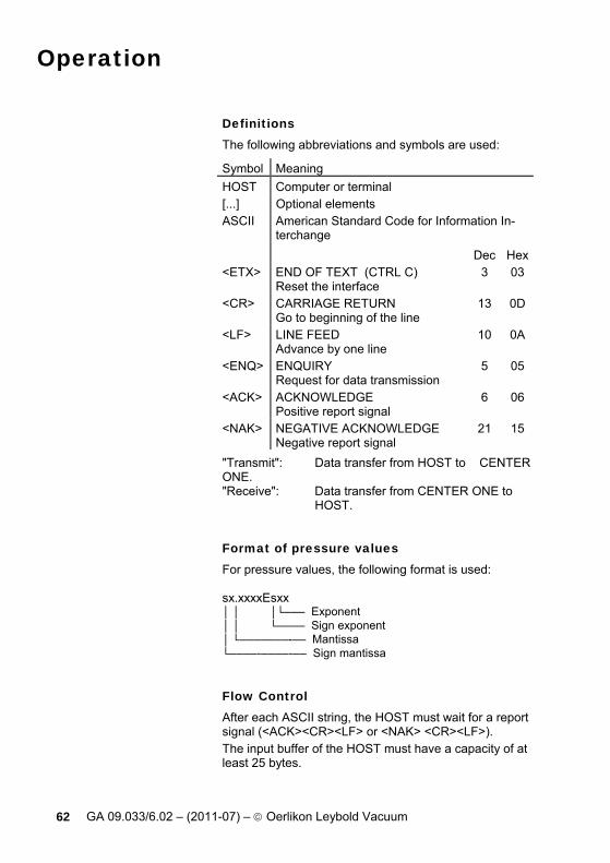
Definitions The following abbreviations and symbols are used:
Symbol Meaning HOST Computer or terminal [...] Optional elements ASCII American Standard Code for Information In-
terchange Dec Hex<ETX> END OF TEXT (CTRL C)
Reset the interface 3 03
<CR> CARRIAGE RETURN Go to beginning of the line
13 0D
<LF> LINE FEED Advance by one line
10 0A
<ENQ> ENQUIRY Request for data transmission
5 05
<ACK> ACKNOWLEDGE Positive report signal
6 06
<NAK> NEGATIVE ACKNOWLEDGE Negative report signal
21 15
"Transmit": Data transfer from HOST to CENTER ONE. "Receive": Data transfer from CENTER ONE to HOST.
Format of pressure values For pressure values, the following format is used: sx.xxxxEsxx │ │ │└─── Exponent │ │ └──── Sign exponent │ └───────-── Mantissa └────-────-── Sign mantissa
Flow Control After each ASCII string, the HOST must wait for a report signal (<ACK><CR><LF> or <NAK> <CR><LF>). The input buffer of the HOST must have a capacity of at least 25 bytes.
Operation
GA 09.033/6.02 – (2011-07) – © Oerlikon Leybold Vacuum 63
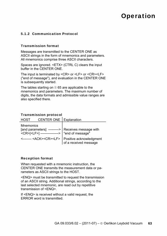
5.1.2 Communication Protocol
Transmission format Messages are transmitted to the CENTER ONE as ASCII strings in the form of mnemonics and parameters. All mnemonics comprise three ASCII characters. Spaces are ignored. <ETX> (CTRL C) clears the input buffer in the CENTER ONE. The input is terminated by <CR> or <LF> or <CR><LF> ("end of message"), and evaluation in the CENTER ONE is subsequently started. The tables starting on 65 are applicable to the mnemonics and parameters. The maximum number of digits, the data formats and admissible value ranges are also specified there.
Transmission protocol HOST CENTER ONE Explanation
Mnemonics [and parameters] ––-–––><CR>[<LF>] –––––––-––>
Receives message with "end of message"
<–-––– <ACK><CR><LF> Positive acknowledgment of a received message
Reception format When requested with a mnemonic instruction, the CENTER ONE transmits the measurement data or pa-rameters as ASCII strings to the HOST. <ENQ> must be transmitted to request the transmission of an ASCII string. Additional strings, according to the last selected mnemonic, are read out by repetitive transmission of <ENQ>. If <ENQ> is received without a valid request, the ERROR word is transmitted.

Operation
64 GA 09.033/6.02 – (2011-07) – © Oerlikon Leybold Vacuum
Reception protocol HOST CENTER ONE Explanation Mnemonics [and parameters] ––––––><CR>[<LF>] –––––––––->
Receives message with "end of message"
<––––- <ACK><CR><LF> Positive acknowledgment of a received message
<ENQ> -–––––––––––––> Requests to transmit <––––––--– Measurement values or parameters <–––––––––– <CR><LF>
Transmits data with "end of message
: : <ENQ>.–––––––––––––> Requests to transmit <––––––--– Measurement values or parameters <–––––––––– <CR><LF>
Transmits data with "end of message"
Error processing All strings received are verified in the CENTER ONE. If an error is detected, a negative acknowledgment <NAK> is output. The appropriate flag is set in the ERROR word. Errors can be decoded when the ERROR word is read.
Error recognition protocol HOST CENTER ONE Explanation Mnemonics [and parameters] ––––-–><CR>[<LF>] -–––––––––>
Receives message with "end of message"
***** Transmission or programming error ***** <–––– <NAK><CR><LF> Negative acknowledgment
of a received message Mnemonics [and parameters] –––––-><CR>[<LF>] –––––-––––>
Receives message with "end of message"
<––––- <ACK><CR><LF> Positive acknowledgment of a received message

Operation
GA 09.033/6.02 – (2011-07) – © Oerlikon Leybold Vacuum 65
5.2 Mnemonics
→ BAU Baud rate 75 COM Continuous mode 67 COR Correction factor 74 DCD Display control digits 75 DGS Degas ITR on/off 70 ERR Error status 69 EUM Emission user mode 75 FIL Filter time constant 74 FSR CTR, DI full scale range 72 FUM Filament user mode 76 HVC HV, EMI on/off 67 ITR ITR / CTR 100, CTR 101 data output 68 LOC Parameter setup lock 78 OFS Offset correction 73 PNR Program number 77 PRE Pirani range extension 76 PR1 Pressure measurement 66 RES Reset 69 SAV Save parameters to EEPROM 76 SP1 Setpoint 70 SPS Setpoint status 71 TAD A/D converter test 80 TDI Display test 80 TEE EEPROM test 79 TEP EPROM test 79 TID Sensor identification 68 TIO I/O test 81 TKB Keyboard test 81 TLC Torr lock 78 TRA RAM test 79 TRS RS232 test 81 UNI Pressure unit 74 WDT Watchdog control 78

Operation
66 GA 09.033/6.02 – (2011-07) – © Oerlikon Leybold Vacuum
5.2.1 Measurement Mode
Measurement data
Transmit: PR1 <CR>[<LF>] Receive: <ACK><CR><LF> Transmit: <ENQ> Receive: x,sx.xxxxEsxx <CR><LF>
│ │ │ └─ Measurement value 1) │ [in current pressure unit] │ └─ Status, x = 0 –> Measurement data okay 1 –> Underrange 2 –> Overrange 3 –> Sensor error 4 –> Sensor off (ITR 100, PTR 225) 5 –> No sensor 6 –> Identification error 7 –> Error ITR
1) The 3rd and 4th decimal are always 0, except for the CTR gauge.

Operation
GA 09.033/6.02 – (2011-07) – © Oerlikon Leybold Vacuum 67
Continuous output of measured values (RS232)
Transmit: COM [,x] <CR>[<LF>] │ └─ Mode x = 0 –> 100 ms 1 –> 1 s (default) 2 –> 1 min.
Receive: <ACK><CR><LF> <ACK> is immediately followed by the con-tinuous output of the measured value in the desired interval.
Receive: x,sx.xxxxEsxx y <CR><LF> │ │ │ │ └───┴─ Measured value 1) │ with pressure unit │ └─ Status, x = 0 –> Measurement data okay 1 –> Underrange 2 –> Overrange 3 –> Sensor error 4 –> Sensor off (ITR 100, PTR 225) 5 –> No sensor 6 –> Identification error 7 –> Error ITR
1) The 3rd and 4th decimal are always 0, except for the CTR gauge.
Activating/deactivating the HV circuit and EMI
Transmit: HVC [,x] <CR>[<LF>] │ └─ Mode x = 0 –> off (default) 1 –> on
Receive: <ACK><CR><LF> Transmit: <ENQ> Receive: x <CR><LF>
│ └─ Mode

Operation
68 GA 09.033/6.02 – (2011-07) – © Oerlikon Leybold Vacuum
Data output ITR, CTR 100, CTR 101
Transmit: ITR <CR>[<LF>] Receive: <ACK><CR><LF> Transmit: <ENQ> Receive, ITR 100: xxx...xxx,y <CR><LF>
│ │ │ └─ Gauge status ERS y │ (→ ITR 100) │ └─ Transmission string (17 character) (→ ITR 100)
Receive, ITR 90 / 200: xx,xx,xx,xx,xx,xx,xx,xx <CR><LF> CTR 100 / 101 │
└─ Transmission string byte 0 … 7 in hex format (→ ITR 90, ITR 200, CTR 100, CTR 101)
Gauge identification
Transmit: TID <CR>[<LF>] Receive: <ACK><CR><LF> Transmit: <ENQ> Receive: x <CR><LF>
│ └─ Identification, x = TTR (Pirani, all versions) TTR100 (Pirani/Capacitive) PTR (Cold cathode) PTR90 (Cold cathode/Pirani) CTR (Capacitive) ITR (Hot cathode) ITR100 (Hot cathode) ITR200 (Hot cathode/Pirani) noSEn (no SEnsor) noid (no identification)

Operation
GA 09.033/6.02 – (2011-07) – © Oerlikon Leybold Vacuum 69
Error status
Transmit: ERR <CR>[<LF>] Receive: <ACK><CR><LF> Transmit: <ENQ> Receive: xxxx <CR><LF>
│ └─ x = 0000 –> No error 1000 –> Controller error (See display on front panel) 0100 –> NO, HWR No hardware 0010 –> PAR, Inadmissible parameter 0001 –> SYN, Syntax error
The ERROR word is cancelled when read out. If the error persists, it is immediately set again.
Reset
Transmit: RES [,x] <CR>[<LF>] │ └─ x = 1 –> Reset
Receive: <ACK><CR><LF> Transmit: <ENQ> Receive: [x]x,[x]x,... <CR><LF>
│ └─ List of all present error messages xx = 0 –> No error 1 –> Watchdog has responded 2 –> Task fail error 5 –> EPROM error 6 –> RAM error 7 –> EEPROM error 9 –> DISPLAY error 10 –> A/D converter error 11 –> Sensor error (e.g. filament rupture, no supply) 12 –> Sensor identification error

Operation
70 GA 09.033/6.02 – (2011-07) – © Oerlikon Leybold Vacuum
5.2.2 Parameter Mode
Degas
Transmit: DGS [,x] <CR>[<LF>] │ └─ x = 0 –> off (default) 1 –> on (3 min.)
Receive: <ACK><CR><LF> Transmit: <ENQ> Receive: x <CR><LF>
│ └─ Degas status
Threshold value setting, allocation
Transmit: SP1 [,x.xxEsx,x.xxEsx] <CR>[<LF>] │ │ │ └─ Upper threshold 1) │ [in current pressure │ unit] │ (default = depending │ on gauge) │ └─ Lower threshold 1) [in current pressure unit] (default = depending on gauge)
1) Values can be entered in any format. They are internally
converted into the floating point format. Receive: <ACK><CR><LF> Transmit: <ENQ> Receive: x.xxxxEsxx,x.xxxxEsxx <CR><LF>
│ │ │ └─ Upper threshold │ [in current pressure unit] │ └─ Lower threshold [in current pressure unit]
Operation
GA 09.033/6.02 – (2011-07) – © Oerlikon Leybold Vacuum 71
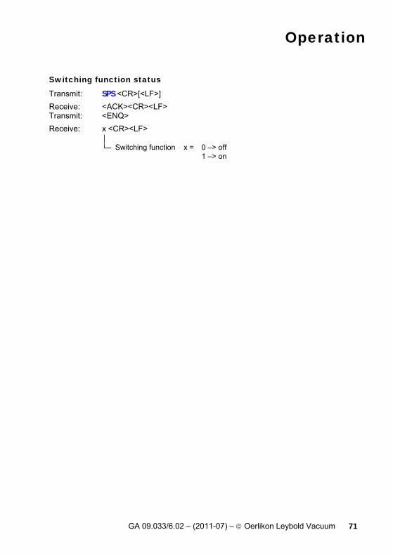
Switching function status
Transmit: SPS <CR>[<LF>] Receive: <ACK><CR><LF> Transmit: <ENQ> Receive: x <CR><LF>
│ └─ Switching function x = 0 –> off 1 –> on
Operation
72 GA 09.033/6.02 – (2011-07) – © Oerlikon Leybold Vacuum
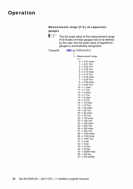
Measurement range (F.S.) of capacitive gauges
The full scale value of the measurement range (Full Scale) of linear gauges has to be defined by the user; the full scale value of logarithmic gauges is automatically recognized.
Transmit: FSR [,x] <CR>[<LF>] │ └─ Measurement range, x = 0 –> 0.01 mbar 1 –> 0.01 Torr 2 –> 0.02 Torr 3 –> 0.05 Torr 4 –> 0.10 mbar 5 –> 0.10 Torr 6 –> 0.25 mbar 7 –> 0.25 Torr 8 –> 0.50 mbar 9 –> 0.50 Torr 10 –> 1 mbar 11 –> 1 Torr 12 –> 2 mbar 13 –> 2 Torr 14 –> 5 mbar 15 –> 5 Torr 16 –> 10 mbar 17 –> 10 Torr 18 –> 20 mbar 19 –> 20 Torr 20 –> 50 mbar 21 –> 50 Torr 22 –> 100 mbar 23 –> 100 Torr 24 –> 200 mbar 25 –> 200 Torr 26 –> 500 mbar 27 –> 500 Torr 28 –> 1000 mbar 29 –> 1100 mbar 30 –> 1000 Torr 31 –> 2 bar 32 –> 5 bar 33 –> 10 bar 34 –> 50 bar 35 –> DI200 mbar 36 –> DI2 bar 37 –> DI2 barRel
Operation
GA 09.033/6.02 – (2011-07) – © Oerlikon Leybold Vacuum 73
Receive: <ACK><CR><LF> Transmit: <ENQ> Receive: x <CR><LF>
│ └─ Measurement range (F.S.)
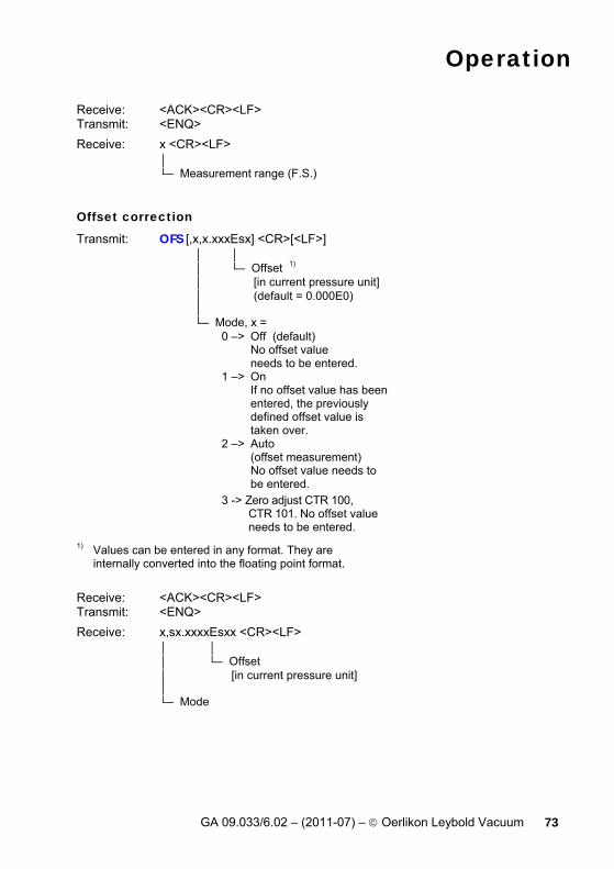
Offset correction
Transmit: OFS [,x,x.xxxEsx] <CR>[<LF>] │ │ │ └─ Offset 1)
│ [in current pressure unit] │ (default = 0.000E0) │ └─ Mode, x = 0 –> Off (default) No offset value needs to be entered. 1 –> On If no offset value has been entered, the previously defined offset value is taken over. 2 –> Auto (offset measurement) No offset value needs to be entered. 3 -> Zero adjust CTR 100, CTR 101. No offset value needs to be entered.
1) Values can be entered in any format. They are
internally converted into the floating point format. Receive: <ACK><CR><LF> Transmit: <ENQ> Receive: x,sx.xxxxEsxx <CR><LF>
│ │ │ └─ Offset │ [in current pressure unit] │ └─ Mode
Operation
74 GA 09.033/6.02 – (2011-07) – © Oerlikon Leybold Vacuum
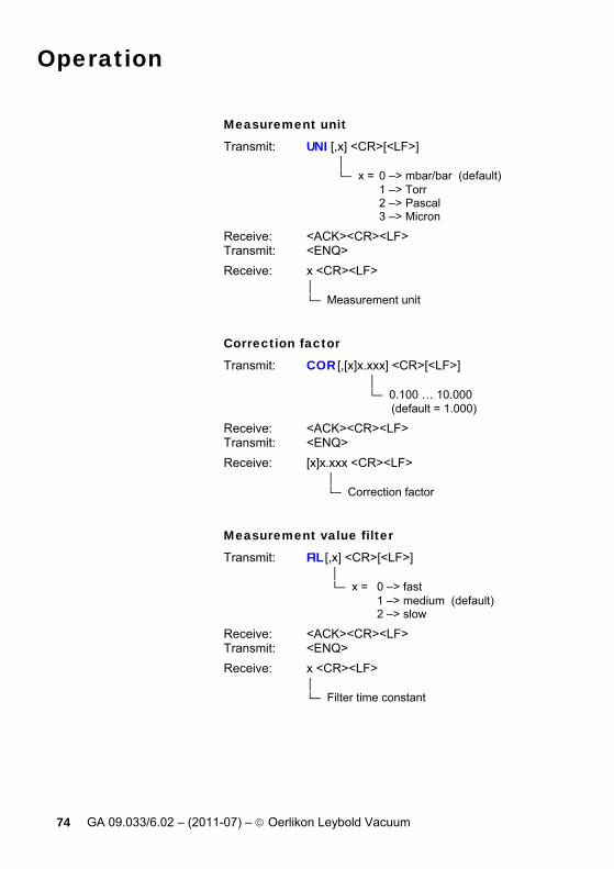
Measurement unit
Transmit: UNI [,x] <CR>[<LF>] │ └─ x = 0 –> mbar/bar (default) 1 –> Torr 2 –> Pascal 3 –> Micron
Receive: <ACK><CR><LF> Transmit: <ENQ> Receive: x <CR><LF>
│ └─ Measurement unit
Correction factor
Transmit: COR [,[x]x.xxx] <CR>[<LF>] │ └─ 0.100 … 10.000 (default = 1.000)
Receive: <ACK><CR><LF> Transmit: <ENQ> Receive: [x]x.xxx <CR><LF>
│ └─ Correction factor
Measurement value filter
Transmit: FIL [,x] <CR>[<LF>] │ └─ x = 0 –> fast 1 –> medium (default) 2 –> slow
Receive: <ACK><CR><LF> Transmit: <ENQ> Receive: x <CR><LF>
│ └─ Filter time constant
Operation
GA 09.033/6.02 – (2011-07) – © Oerlikon Leybold Vacuum 75
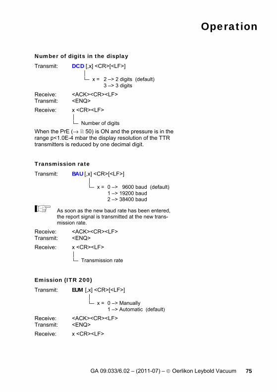
Number of digits in the display
Transmit: DCD [,x] <CR>[<LF>] │ └─ x = 2 –> 2 digits (default) 3 –> 3 digits
Receive: <ACK><CR><LF> Transmit: <ENQ> Receive: x <CR><LF>
│ └─ Number of digits
When the PrE (→ 50) is ON and the pressure is in the range p<1.0E-4 mbar the display resolution of the TTR transmitters is reduced by one decimal digit.
Transmission rate
Transmit: BAU [,x] <CR>[<LF>] │ └─ x = 0 –> 9600 baud (default) 1 –> 19200 baud 2 –> 38400 baud
As soon as the new baud rate has been entered, the report signal is transmitted at the new trans-mission rate.
Receive: <ACK><CR><LF> Transmit: <ENQ> Receive: x <CR><LF>
│ └─ Transmission rate
Emission (ITR 200)
Transmit: EUM [,x] <CR>[<LF>] │ └─ x = 0 –> Manually 1 –> Automatic (default)
Receive: <ACK><CR><LF> Transmit: <ENQ> Receive: x <CR><LF>

Operation
76 GA 09.033/6.02 – (2011-07) – © Oerlikon Leybold Vacuum
Filament (ITR 200)
Transmit: FUM [,x] <CR>[<LF>] │ └─ x = 0 –> Automatic (default) 1 –> Filament 1 2 –> Filament 2
Receive: <ACK><CR><LF> Transmit: <ENQ> Receive: x <CR><LF>
Save parameters to EEPROM
Transmit: SAV [,x] <CR>[<LF>] │ └─ x = 0 –> Save default parameters 1 –> Save user parameters
Receive: <ACK><CR><LF>
Pirani range extension
Transmit: PRE [,x] <CR>[<LF>] │ └─ x = 0 –> off (default) 1 –> on
Receive: <ACK><CR><LF> Transmit: <ENQ> Receive: x <CR><LF>
TTR transmitters only, measurement range down to 5×10⁻⁵ mbar.
Operation
GA 09.033/6.02 – (2011-07) – © Oerlikon Leybold Vacuum 77
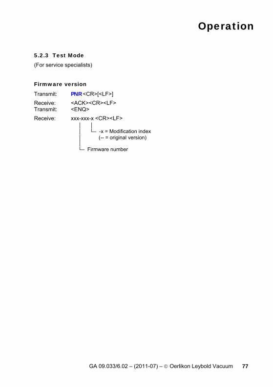
5.2.3 Test Mode (For service specialists)
Firmware version
Transmit: PNR <CR>[<LF>] Receive: <ACK><CR><LF> Transmit: <ENQ> Receive: xxx-xxx-x <CR><LF>
│ │ │ └─ -x = Modification index │ (-- = original version) │ └─ Firmware number
Operation
78 GA 09.033/6.02 – (2011-07) – © Oerlikon Leybold Vacuum
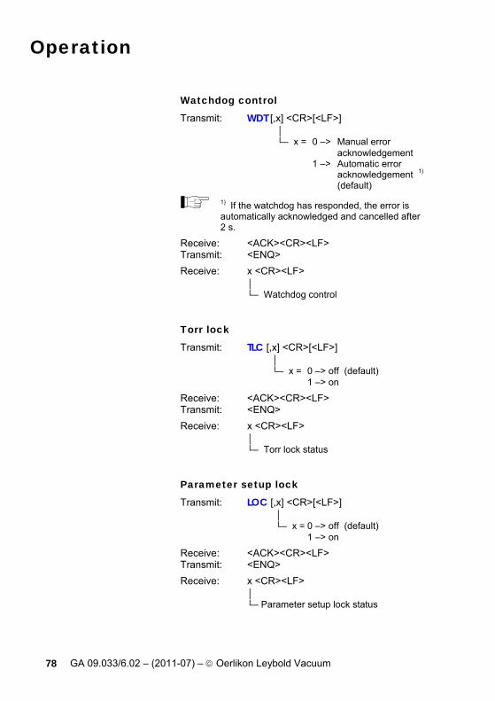
Watchdog control
Transmit: WDT [,x] <CR>[<LF>] │ └─ x = 0 –> Manual error acknowledgement 1 –> Automatic error acknowledgement 1) (default)
1) If the watchdog has responded, the error is automatically acknowledged and cancelled after 2 s.
Receive: <ACK><CR><LF> Transmit: <ENQ> Receive: x <CR><LF>
│ └─ Watchdog control
Torr lock
Transmit: TLC [,x] <CR>[<LF>] │ └─ x = 0 –> off (default) 1 –> on
Receive: <ACK><CR><LF> Transmit: <ENQ> Receive: x <CR><LF>
│ └─ Torr lock status
Parameter setup lock
Transmit: LOC [,x] <CR>[<LF>] │ └─ x = 0 –> off (default) 1 –> on
Receive: <ACK><CR><LF> Transmit: <ENQ> Receive: x <CR><LF>
│ └─ Parameter setup lock status
Operation
GA 09.033/6.02 – (2011-07) – © Oerlikon Leybold Vacuum 79
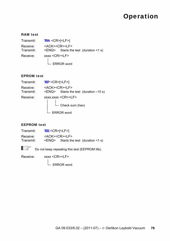
RAM test
Transmit: TRA <CR>[<LF>] Receive: <ACK><CR><LF> Transmit: <ENQ> Starts the test (duration <1 s) Receive: xxxx <CR><LF>
│ └─ ERROR word
EPROM test
Transmit: TEP <CR>[<LF>] Receive: <ACK><CR><LF> Transmit: <ENQ> Starts the test (duration ≈10 s) Receive: xxxx,xxxx <CR><LF>
│ │ │ └─ Check sum (hex) │ └─ ERROR word
EEPROM test
Transmit: TEE <CR>[<LF>] Receive: <ACK><CR><LF> Transmit: <ENQ> Starts the test (duration <1 s)
Do not keep repeating this test (EEPROM life).
Receive: xxxx <CR><LF> │ └─ ERROR word

Operation
80 GA 09.033/6.02 – (2011-07) – © Oerlikon Leybold Vacuum
Display test
Transmit: TDI [,x] <CR>[<LF>] │ └─ x = 0 –> Stops the test – display according to current operating mode (default) 1 –> Starts the test – all LEDs on
Receive: <ACK><CR><LF> Transmit: <ENQ> Receive: x <CR><LF>
│ └─ Display test status
ADC test
Transmit: TAD <CR>[<LF>] Receive: <ACK><CR><LF> Transmit: <ENQ> Receive: [x]x.xxxx, x.xxxx, x.xxxx <CR><LF>
│ │ │ │ │ └─ ADC channel 2 │ │ Gauge │ │ identification │ │ [0.0000 … │ │ 5.0000 V] │ │ │ └─ ADC channel 1 │ Measurement signal │ (negative portion) │ [0.0000 … 5.0000 V] │ └─ ADC channel 0 Measurement signal (positive portion) [0.0000 … 11.0000 V]

Operation
GA 09.033/6.02 – (2011-07) – © Oerlikon Leybold Vacuum 81
I/O test
Transmit: TIO [,x] <CR>[<LF>] │ └─ x = 0 –> Stops the test (default) 1 –> Setpoint relay off, error relay off 2 –> Setpoint relay on, error relay off 3 –> Setpoint relay off, error relay on 4 –> Setpoint relay on, error relay on
Receive: <ACK><CR><LF> Transmit: <ENQ> Receive: x <CR><LF>
│ └─ I/O test status
Operator key test
Transmit: TKB <CR>[<LF>] Receive: <ACK><CR><LF> Transmit: <ENQ> Receive: xxx <CR><LF>
│││ ││└─ Key 3 x = 0 –> Not pushed ││ 1 –> Pushed ││ │└── Key 2 │ └─── Key 1
RS232 test
Transmit: TRS <CR>[<LF>] Receive: <ACK><CR><LF> Transmit: <ENQ> Starts the test (repeats each character, test is interrupted with <CTRL> C).
Operation
82 GA 09.033/6.02 – (2011-07) – © Oerlikon Leybold Vacuum
5.2.4 Example
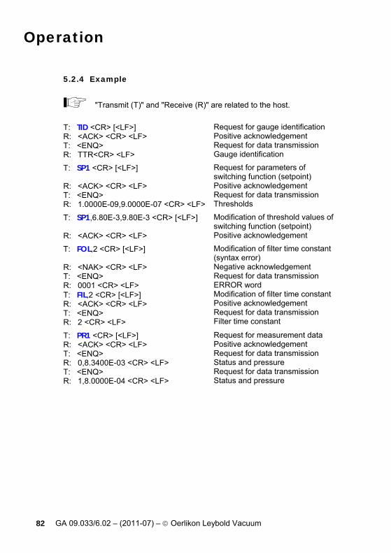
"Transmit (T)" and "Receive (R)" are related to the host.
T: TID <CR> [<LF>] R: <ACK> <CR> <LF> T: <ENQ> R: TTR<CR> <LF>
Request for gauge identification Positive acknowledgement Request for data transmission Gauge identification
T: SP1 <CR> [<LF>] R: <ACK> <CR> <LF> T: <ENQ> R: 1.0000E-09,9.0000E-07 <CR> <LF>
Request for parameters of switching function (setpoint) Positive acknowledgement Request for data transmission Thresholds
T: SP1,6.80E-3,9.80E-3 <CR> [<LF>] R: <ACK> <CR> <LF>
Modification of threshold values ofswitching function (setpoint) Positive acknowledgement
T: FOL,2 <CR> [<LF>] R: <NAK> <CR> <LF> T: <ENQ> R: 0001 <CR> <LF> T: FIL,2 <CR> [<LF>] R: <ACK> <CR> <LF> T: <ENQ> R: 2 <CR> <LF>
Modification of filter time constant (syntax error) Negative acknowledgement Request for data transmission ERROR word Modification of filter time constant Positive acknowledgement Request for data transmission Filter time constant
T: PR1 <CR> [<LF>] R: <ACK> <CR> <LF> T: <ENQ> R: 0,8.3400E-03 <CR> <LF> T: <ENQ> R: 1,8.0000E-04 <CR> <LF>
Request for measurement data Positive acknowledgement Request for data transmission Status and pressure Request for data transmission Status and pressure

Maintenance
GA 09.033/6.02 – (2011-07) – © Oerlikon Leybold Vacuum 83
6 Maintenance
The product requires no maintenance.
Cleaning CENTER ONE For cleaning the outside of CENTER ONE, a slightly moist cloth will usually do. Do not use any aggressive or scouring cleaning agents.
DANGER
DANGER: mains voltage Contact with live parts is extremely hazardous when liquids penetrate into the unit. Make sure no liquids penetrate into the equipment.

Troubleshooting
84 GA 09.033/6.02 – (2011-07) – © Oerlikon Leybold Vacuum
7 Troubleshooting
Signalization of errors
and the error relay opens (→ 26).
Error messages Possible cause and remedy/
acknowledgement
Interruption or instability in sensor line or connector (Sensor error).
Acknowledge with the "PARA" key. If the problem persists,
or is displayed.
Possible cause and remedy/
acknowledgement
CENTER ONE has been turned on too fast after power OFF.
Acknowledge with the "PARA" key. If the watchdog is set to "Auto", CENTER ONE acknowledges the message automatically after 2 s (→ 54).
The watchdog has tripped because of severe electric disturbance or an oper-ating system error.
Acknowledge with the "PARA" key. If the watchdog is set to "Auto", CENTER ONE acknowledges the message automatically after 2 s (→ 54).

Troubleshooting
GA 09.033/6.02 – (2011-07) – © Oerlikon Leybold Vacuum 85
Possible cause and remedy/ acknowledgement
Main memory (RAM) error.
Acknowledge with the "PARA" key. Possible cause and remedy/
acknowledgement
Program memory (EPROM) error.
Acknowledge with the "PARA" key. Possible cause and remedy/
acknowledgement
Parameter memory (EEPROM) error.
Acknowledge with the "PARA" key. Possible cause and remedy/
acknowledgement
Display driver error.
Acknowledge with the "PARA" key. Possible cause and remedy/
acknowledgement
A/D converter error.
Acknowledge with the "PARA" key. Possible cause and remedy/
acknowledgement
Operating system (Task Fail) error.
Acknowledge with the "PARA" key.
Technical support
If the problem persists after the message has been acknowledged for several times and/or the gauge has been exchanged, please contact you local Leybold Vakuum service center.
Accessories, Storage
86 GA 09.033/6.02 – (2011-07) – © Oerlikon Leybold Vacuum
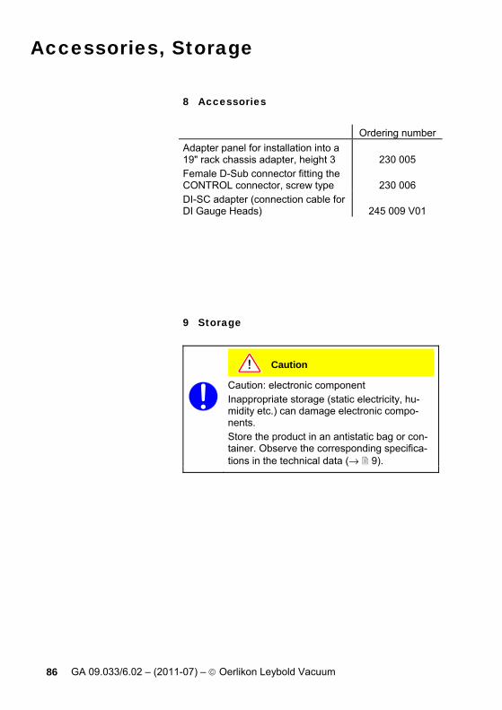
8 Accessories
Ordering number Adapter panel for installation into a 19" rack chassis adapter, height 3
230 005
Female D-Sub connector fitting the CONTROL connector, screw type
230 006
DI-SC adapter (connection cable for DI Gauge Heads)
245 009 V01
9 Storage
Caution
Caution: electronic component Inappropriate storage (static electricity, hu-midity etc.) can damage electronic compo-nents. Store the product in an antistatic bag or con-tainer. Observe the corresponding specifica-tions in the technical data (→ 9).

Disposal
GA 09.033/6.02 – (2011-07) – © Oerlikon Leybold Vacuum 87
10 Disposal
WARNING
WARNING: substances detrimental to the environment Products or parts thereof (mechanical and electric components, operating fluids etc.) can be detrimental to the environment. Dispose of such substances in accordance with the relevant local regulations.
Separating the components After disassembling the product, separate its compo-nents according to the following criteria:
Non-electronic components Such components must be separated according to their materials and recycled.
Electronic components Such components must be separated according to their materials and recycled.
Appendix
88 GA 09.033/6.02 – (2011-07) – © Oerlikon Leybold Vacuum
Appendix
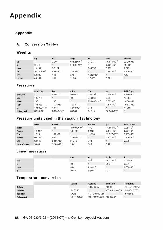
A: Conversion Tables
Weights
kg lb slug oz cwt sh cwt kg 1 2.205 68.522×10⁻³ 35.274 19.684×10⁻³ 22.046×10⁻³ lb 0.454 1 31.081×10⁻³ 16 8.929×10⁻³ 10×10-3 slug 14.594 32.174 1 514.785 0.287 0.322 oz 28.349×10⁻³ 62.5×10⁻³ 1.943×10⁻³ 1 0.588×10⁻³ 0.625×10⁻³ cwt 50.802 112 3.481 1.792×10³ 1 1.12 sh cwt 45.359 100 3.108 1.6·103 0.893 1
Pressures
N/m2, Pa bar mbar Torr at lbf/in2, psi N/m2, Pa 1 10×10-6 10×10-3 7.5×10⁻³ 9.869×10⁻⁶ 0.145×10⁻³
bar 100×103 1 103 750.062 0.987 14.504 mbar 100 10-3 1 750.062×10⁻³ 0.987×10⁻³ 14.504×10⁻³ Torr 133.322 1.333×10⁻³ 1.333 1 1.316×10⁻³ 19.337×10⁻³ at 101.325×10³ 1.013 1.013×10³ 760 1 14.696 lbf/in2, psi 6.895×10³ 68.948×10⁻³ 68.948 51.715 68.046×10⁻³ 1
Pressure units used in the vacuum technology
mbar Pascal Torr mmWs psi inch of merc. mbar 1 100 750.062×10⁻³ 10.2 14.504×10⁻³ 2.95×10⁻² Pascal 10×10-3 1 7.5×10⁻³ 0.102 0.145×10⁻³ 2.95×10⁻⁴ Torr 1.333 133.332 1 13.595 19.337×10⁻³ 3.937×10⁻² mmWs 9.81×10⁻² 9.81 7.356×10⁻² 1 1.422×10⁻³ 2.896×10⁻³ psi 68.948 6.895×10³ 51.715 703 1 2.036 inch of merc. 33.86 3.386×10³ 25.4 345 0.491 1
Linear measures
mm m inch ft mm 1 10-3 39.37×10⁻³ 3.281×10⁻³ m 103 1 39.37 3.281 inch 25.4 25.4×10⁻³ 1 8.333×10⁻² ft 304.8 0.305 12 1
Temperature conversion
Kelvin Celsius Rankine Fahrenheit Kelvin 1 °C+273.15 °R×5/9 (°F+459.67)×5/9 Celsius K-273.15 1 (°R-491.69)×5/9 5/9×°F-17.778 Rankine K×9/5 (°C×9/5)+491.69 1 °F+459.67 Fahrenheit 9/5×K-459.67 9/5×(°C+17.778) °R-459.67 1
Appendix
GA 09.033/6.02 – (2011-07) – © Oerlikon Leybold Vacuum 89
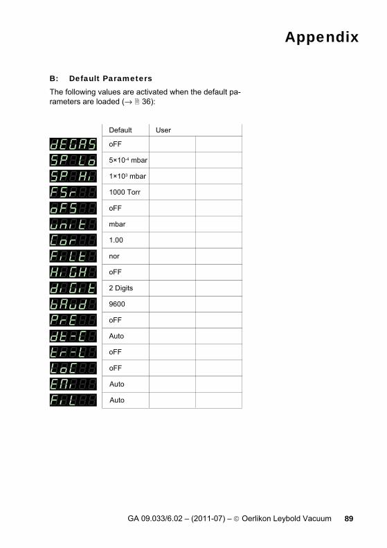
B: Default Parameters The following values are activated when the default pa-rameters are loaded (→ 36):
mbar
oFF
1000 Torr
1×10³ mbar
5×10⁻⁴ mbar
oFF
1.00
nor
oFF
9600
Auto
oFF
2 Digits
oFF
Auto
Auto
oFF
Default User

Appendix
90 GA 09.033/6.02 – (2011-07) – © Oerlikon Leybold Vacuum
C: Firmware Update
If your CENTER ONE firmware needs updating, e.g. for implementing a new gauge type, please contact your local Leybold Vakuum service center.
User parameters Most of the settings you may have defined in the Pa-rameter and Test mode will not be affected by a firm-ware update. To be sure, note your parameter settings before upgrading the firmware (→ 89).
Preparing CENTER ONE for a program transfer
• Turn CENTER ONE off
• Connect CENTER ONE with the serial COM1 (COM2) interface of your PC via a 9-pin D-Sub ex-tension cable (the firmware of CENTER ONE cannot be loaded from a Mac).
• With a pin (ø<2 mm) depress the switch behind the rear panel and turn CENTER ONE on.
After power ON, the display remains dark.

Appendix
GA 09.033/6.02 – (2011-07) – © Oerlikon Leybold Vacuum 91
Programmtransfer
Unpack the self extracting file *.exe or the packed*.zip file.
If you have not connected CENTER ONE to the COM1 interface: Open the batch file Update BG509763-A, …
… edit the interface, …
… and save the new setting.
Start batch file Update BG509763-A.

Appendix
92 GA 09.033/6.02 – (2011-07) – © Oerlikon Leybold Vacuum
The new firmware is transmitted to CENTER ONE.
Starting CENTER ONE with the updated firm-ware If the program transfer was successful, quit the Update mode by turning CENTER ONE off.
Wait at least 10 s before turning CENTER ONE on again in order for it to correctly initialize it-self.
CENTER ONE is now ready for operation. To be sure, check that the current parameter settings are identical with the previously defined settings (→ 89).

Appendix
GA 09.033/6.02 – (2011-07) – © Oerlikon Leybold Vacuum 93
D: Literature [1] www.oerlikon.com
Operating Manual THERMOVAC Transmitter TTR 90 GA 09.220/1.02 Oerlikon Leybold Vacuum GmbH, D–50968 Köln, Deutschland
[2] www.oerlikon.com Operating Manual THERMOVAC Transmitter TTR 91, TTR 91 S GA 09.222/1.02 Oerlikon Leybold Vacuum GmbH, D–50968 Köln, Deutschland
[3] www.oerlikon.com Operating Manual THERMOVAC Transmitter TTR 96 S GA 09.223/1.02 Oerlikon Leybold Vacuum GmbH, D–50968 Köln, Deutschland
[4] www.oerlikon.com Operating Manual THERMOVAC Transmitter TTR 211 S GA 09.216/1.02 Oerlikon Leybold Vacuum GmbH, D–50968 Köln, Deutschland
[5] www.oerlikon.com Operating Manual THERMOVAC Transmitter TTR 100, TTR 100 S2 GA 09.221/1.02 Oerlikon Leybold Vacuum GmbH, D–50968 Köln, Deutschland
[6] www.oerlikon.com Operating Manual THERMOVAC Transmitter TTR 101, TTR 101 S2 300344581_002_A0 Oerlikon Leybold Vacuum GmbH, D–50968 Köln, Deutschland
[7] www.oerlikon.com Operating Manual PENNING Transmitter PTR 225 GA 09.308/1.02 Oerlikon Leybold Vacuum GmbH, D–50968 Köln, Deutschland

Appendix
94 GA 09.033/6.02 – (2011-07) – © Oerlikon Leybold Vacuum
[8] www.oerlikon.com Operating Manual CERAVAC Transmitter CTR 90 GA 09.040/1.02 Oerlikon Leybold Vacuum GmbH, D–50968 Köln, Deutschland
[9] www.oerlikon.com Operating Manual CERAVAC Transmitter CTR 91 GA 09.040/1.02 Oerlikon Leybold Vacuum GmbH, D–50968 Köln, Deutschland
[10] www.oerlikon.com Operating Manual IONIVAC Transmitter ITR 90 GA 09.420/1.02 Oerlikon Leybold Vacuum GmbH, D–50968 Köln, Deutschland
[11] www.oerlikon.com Operating Manual IONIVAC Transmitter ITR 100 GA 09.414/1.02 Oerlikon Leybold Vacuum GmbH, D–50968 Köln, Deutschland
[12] www.oerlikon.com Operating Manual PENNINGVAC Transmitter PTR 90 GA 09.313/1.02 Oerlikon Leybold Vacuum GmbH, D–50968 Köln, Deutschland
[13] www.oerlikon.com Operating Manual IONIVAC Transmitter ITR 200 17200137_002_00 Oerlikon Leybold Vacuum GmbH, D–50968 Köln, Deutschland
[14] www.oerlikon.com Gebrauchsanleitung Messkopf DI 200, DI 201, DI 2000, DI 2001, DI 2001 rel GA09611_001_A1 Oerlikon Leybold Vacuum GmbH, D–50968 Köln, Deutschland
Appendix
GA 09.033/6.02 – (2011-07) – © Oerlikon Leybold Vacuum 95
[15] www.oerlikon.com Gebrauchsanleitung CERAVAC-Transmitter CTR 100 17200257_001_00 Oerlikon Leybold Vacuum GmbH, D–50968 Köln, Deutschland
[16] www.oerlikon.com Gebrauchsanleitung CERAVAC-Transmitter CTR 101 130002066_001_A0 Oerlikon Leybold Vacuum GmbH, D–50968 Köln, Deutschland
Index
96 GA 09.033/6.02 – (2011-07) – © Oerlikon Leybold Vacuum
E: Index A/D 57 Accessories 86 Baud 49 Cleaning 83 Communication
Example 82 Mnemonics 65 RS232C-Interface 61
Connectors CONTROL 26 Mains power 22 RS232 interface 25 SENSOR 23
CONTROL connector 26 Conversion 88 Correction 45 Default parameters 36, 89 Degas 38 Display 56
Resolution 48 Disposal 87 EEPROM 56 Emission 49 EPROM 55 Error messages 84 Filament 49 Firmware
Update 90 Version 2, 53
Full Scale → Measurement range Gauge 48 Gauge connector 23 Gauge identification 33 I/O 59 Interface connector 25 Literature 93 Mains power connector 22 Maintenance 83 Measurement 42, 45, 46 Measurement mode 31, 32, 33
Mnemonics → Communication Mode → Operating modes Offset 43, 44 Operating 51 Operating modes 30, 34, 90 Operation: 29 Parameter 38, 42, 43, 44, 45, 46, 48, 49, 50, 54 Parameter mode 35 Pirani 50 Power connector 22 Power OFF 29 Power ON 29 Program → Firmware
Update 90 Version 2
RAM 55 RS232 interface connector 25 RS232C 60 Safety 6 SENSOR connector 23 Status messages 28 Storage 86 Switching 38 Switching function 26 Test 52, 53, 54, 55, 56, 57, 59, 60 Thresholds 38 Torr 54 Transmission 49 Troubleshooting 84 Update 90 Warranty 8 Watchdog 54
EC Declaration of Conformity
GA 09.033/6.02 – (2011-07) – © Oerlikon Leybold Vacuum 97

Notes
98 GA 09.033/6.02 – (2011-07) – © Oerlikon Leybold Vacuum

Notes
GA 09.033/6.02 – (2011-07) – © Oerlikon Leybold Vacuum 99

Oerlikon Leybold Vacuum GmbH Bonner Strasse 498 D-50968 Köln Tel: +49-(0)221-347 1234 Fax: +49-(0)221-347 1245 [email protected]
w w w . o e r l i k o n . c o m
Original: German GA 09.033/6.01 (2011-07)
ga09. 033/ 6. 02


![[Presenticcon Pilot] Rang Mudo Nak Singkarak](https://static.documents.pub/doc/80x56/55b1d3a6bb61eb6a368b46cf/presenticcon-pilot-rang-mudo-nak-singkarak.jpg)
