Installation Instructions Original Instructions CENTERLINE 2100 Motor Control Center (MCC) Doors and Units with Vertical Operating Handles Bulletin Number 2100 About This Publication Use these instructions to install CENTERLINE® 2100 MCC units with vertical operating handles. Topic Page About This Publication 1 Important User Information 2 Before You Begin 3 Recommended Tools 4 Ground the Unit 4 Install the Unit Support Pan 4 Install Swing-out Latch Brackets 7 Install the Unit 7 Install the Door 10 Extend SecureConnect Unit Power Stabs 12 Additional Resources 13 ATTENTION: All covers and doors must be in place before you apply power to the MCC. If units are removed, they must be replaced with the appropriate items such as units, doors, and unit support pans. If the unit is not replaced, the arc resistant rating does not apply.
Transcript
Installation Instructions
Original Instructions
CENTERLINE 2100 Motor Control Center (MCC) Doors and Units with Vertical Operating HandlesBulletin Number 2100
About This PublicationUse these instructions to install CENTERLINE® 2100 MCC units with vertical operating handles.
Topic Page
About This Publication 1
Important User Information 2
Before You Begin 3
Recommended Tools 4
Ground the Unit 4
Install the Unit Support Pan 4
Install Swing-out Latch Brackets 7
Install the Unit 7
Install the Door 10
Extend SecureConnect Unit Power Stabs 12
Additional Resources 13
ATTENTION: All covers and doors must be in place before you apply power to the MCC. If units are removed, they must be replaced with the appropriate items such as units, doors, and unit support pans. If the unit is not replaced, the arc resistant rating does not apply.
CENTERLINE 2100 Motor Control Center (MCC) Doors and Units with Vertical Operating Handles
Important User InformationRead this document and the documents listed in the additional resources section about installation, configuration, and operation of this equipment before you install, configure, operate, or maintain this product. Users are required to familiarize themselves with installation and wiring instructions in addition to requirements of all applicable codes, laws, and standards.
Activities including installation, adjustments, putting into service, use, assembly, disassembly, and maintenance are required to be carried out by suitably trained personnel in accordance with applicable code of practice.
If this equipment is used in a manner not specified by the manufacturer, the protection provided by the equipment may be impaired.
In no event will Rockwell Automation, Inc. be responsible or liable for indirect or consequential damages resulting from the use or application of this equipment.
The examples and diagrams in this manual are included solely for illustrative purposes. Because of the many variables and requirements associated with any particular installation, Rockwell Automation, Inc. cannot assume responsibility or liability for actual use based on the examples and diagrams.
No patent liability is assumed by Rockwell Automation, Inc. with respect to use of information, circuits, equipment, or software described in this manual.
Reproduction of the contents of this manual, in whole or in part, without written permission of Rockwell Automation, Inc., is prohibited.
Throughout this manual, when necessary, we use notes to make you aware of safety considerations.
Labels may also be on or inside the equipment to provide specific precautions.
WARNING: Identifies information about practices or circumstances that can cause an explosion in a hazardous environment, which may lead to personal injury or death, property damage, or economic loss.
ATTENTION: Identifies information about practices or circumstances that can lead to personal injury or death, property damage, or economic loss. Attentions help you identify a hazard, avoid a hazard, and recognize the consequence.
IMPORTANT Identifies information that is critical for successful application and understanding of the product.
SHOCK HAZARD: Labels may be on or inside the equipment, for example, a drive or motor, to alert people that dangerous voltage may be present.
BURN HAZARD: Labels may be on or inside the equipment, for example, a drive or motor, to alert people that surfaces may reach dangerous temperatures.
ARC FLASH HAZARD: Labels may be on or inside the equipment, for example, a motor control center, to alert people to potential Arc Flash. Arc Flash will cause severe injury or death. Wear proper Personal Protective Equipment (PPE). Follow ALL Regulatory requirements for safe work practices and for Personal Protective Equipment (PPE).
2 Rockwell Automation Publication 2100-IN014H-EN-P - June 2018
CENTERLINE 2100 Motor Control Center (MCC) Doors and Units with Vertical Operating Handles
Before You BeginFollow this procedure before you begin installing your unit.
1. Remove all packaging material from the unit.
2. Read the unit installation instructions.
3. Familiarize yourself with the unit.
4. Inspect unit for any damage that is caused during shipment.
5. To verify proper operation, manually exercise all switches, control auxiliary switches, circuit breakers, their respective operators, unit interlocks, trip mechanisms (test by pushing the ‘Push to Trip’ button), and any other operating mechanisms.
6. For SecureConnect™ units, verify that power stabs fully extend and retract.
ATTENTION: When you install units for CENTERLINE 2100 motor control centers with ArcShield™ baffles, you must make sure that you are installing a unit that has the same arc resistance rating as the MCC in which it is being installed. Units that are not rated for 100 ms arc duration must not be installed in a section that is rated for 100 ms arc duration. If the incorrect unit is installed, the arc resistant rating does not apply.
ATTENTION: SecureConnect units must be installed in Series P or later CENTERLINE 2100 motor control centers. If you install a SecureConnect unit in a Series N or earlier MCC, you must have compatible bus covers installed. For more information, contact your local Allen-Bradley distributor or Rockwell Automation sales representative.
Unit
Unit Door
Unit Support Pan
Series N or Earlier Bus Cover Stab Openings
Series P or Later Bus Cover Stab Openings
Rockwell Automation Publication 2100-IN014H-EN-P - June 2018 3
CENTERLINE 2100 Motor Control Center (MCC) Doors and Units with Vertical Operating Handles
Recommended ToolsYou need the following tools:
• Screwdriver• 5/16 in. and a 3/8 in. socket wrench, for installing ArcShield units• 1/4 in. hex tool, for installing SecureConnect units• Multi-meter with fine-point probes
Ground the UnitFollow this procedure to ground the unit.
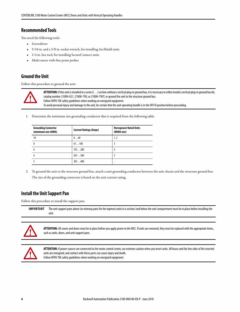
1. Determine the minimum size grounding-conductor that is required from the following table.
2. To ground the unit to the structure ground bus, attach a unit grounding conductor between the unit chassis and the structure ground bus.
The size of the grounding connector is based on the unit current rating.
Install the Unit Support PanFollow this procedure to install the support pan.
ATTENTION: If this unit is installed in a series E…J section without a vertical plug-in ground bus, it is necessary to either install a vertical plug-in ground bus kit, catalog number 2100H-GS1, 2100H-79U, or 2100H-79UT, or ground the unit to the structure ground bus.Follow NFPA 70E safety guidelines when working on energized equipment.To avoid personal injury and damage to the unit, be certain that the unit operating handle is in the OFF/O position before proceeding.
Grounding Connector (minimum size #AWG)
Current Ratings (Amps)Horsepower Rated Units(NEMA size)
10 0…60 1, 2
8 61…100 3
6 101…200 4
4 201…300 5
3 301…400 -
IMPORTANT The unit support pans above (or wireway pans for the topmost units in a section) and below the unit compartment must be in place before installing the unit.
ATTENTION: All covers and doors must be in place before you apply power to the MCC. If units are removed, they must be replaced with the appropriate items, such as units, doors, and unit support pans.
ATTENTION: If power sources are connected to the motor control center, use extreme caution when you insert units. All buses and the line sides of the inserted units are energized, and contact with these parts can cause injury and death.Follow NFPA 70E safety guidelines when working on energized equipment.
4 Rockwell Automation Publication 2100-IN014H-EN-P - June 2018
CENTERLINE 2100 Motor Control Center (MCC) Doors and Units with Vertical Operating Handles
1. For ArcShield sections with 100 ms arc duration rating, remove the vertical wireway baffle and set aside for installation later.
2. If present, remove the isolation barrier from the vertical-wireway wall cutout.
3. De-energize the unit in the space below where the unit support pan is to be installed.
4. Open the unit door above and below where the unit support pan is to be installed.
5. Place the unit support pan into the unit space, hold the right side of the support pan approximately 4 in. (100 mm) higher than the left side.
6. Place the left front corner of the support pan into the slot on the front of the left sidesheet flange.
7. Place the left rear corner of the support pan into the slot of the left sidesheet C-channel.
8. Lower the right edge of the unit support pan into the vertical-wireway wall cutout, and press down firmly.
Rockwell Automation Publication 2100-IN014H-EN-P - June 2018 5
CENTERLINE 2100 Motor Control Center (MCC) Doors and Units with Vertical Operating Handles
9. Secure the support pan.
See the table for more instructions.
Non ArcShield Unit Support Pan Installation
ArcShield Unit Support Pan Installation
10. Replace the isolation barrier if one was removed.
For Follow This Step
Non ArcShield units Insert the white plastic retaining-clip through the holes in the vertical wireway wall and pan, work from inside the vertical wireway as shown. See Non ArcShield Unit Support Pan Installation.
All ArcShield units Secure the unit support pan to the right unit support with the 1/4-20 self-tapping screw that is supplied with the bracket and tighten to 55 lb•in (6 N•m) with a 3/8 in. socket wrench. See ArcShield Unit Support Pan Installation.
ArcShield units with 100 ms arc duration rating Secure the left-rear corner of the unit support pan with a 10-32 self-tapping screw and tighten to 32 lb•in (3.6 N•m) by using a 5/16 in. socket wrench.
Plastic Retaining Clip
Unit Support Pan
Unit Support Pan Screw
Arc Resistant Latch Bracket
Arc Resistant Latch Bracket Screw
Unit Support Pan
Isolation Barrier
6 Rockwell Automation Publication 2100-IN014H-EN-P - June 2018
CENTERLINE 2100 Motor Control Center (MCC) Doors and Units with Vertical Operating Handles
Install Swing-out Latch BracketsSwing-out latch brackets are used on ArcShield units with 100 ms arc duration rating that have more than two latches (for example, in the middle latch position).
1. Work from the inside of the vertical wireway cutout, place the swing-out latch bracket on the back of the front flange of the right unit support.
2. Align the latch bracket with the slot in the right unit support so that the alignment tab of the bracket is resting on the bottom of the slot.
3. Work from the inside of the vertical wireway and tighten the two 10-32 self-tapping screws to 32 lb•in (3.6 N•m) to secure the swing-out latch bracket to the right unit support.
Install the UnitFollow this procedure to install the unit.
1. Remove the protective caps from the stab openings or open the manual shutters if present (automatic shutters open as the units are inserted).
ATTENTION: De-energize all units before installing or removing.
When you install or remove MCC units, when possible, de-energize, lockout, and tag-out all sources of power to the MCC. If the MCC units are installed or with power that is applied to the main power bus, follow established electrical safety work practices. See the NFPA 70E Standard for Electrical Safety in the Workplace publication.
Review your company safety lockout and tag-out procedure.
If power sources are connected to the motor control center, use extreme caution when you insert units. All buses and the line sides of the inserted units are energized, and contact with these parts can cause injury or death.
All covers and doors must be in place before you apply power to the MCC. If units are removed, they must be replaced with the appropriate items, such as units, doors, and unit support pans.
ATTENTION: Plug-in MCC units can be heavy or awkward to handle. Use an assistant or a platform lift device if necessary to help you handle the unit.
Vertical Wireway
Alignment Tab
Vertical Wireway Cutout
Swing-out Latch Bracket
Right Unit Support
Swing-out Latch
Screw
Screw
Vertical Wireway Side
Rockwell Automation Publication 2100-IN014H-EN-P - June 2018 7
CENTERLINE 2100 Motor Control Center (MCC) Doors and Units with Vertical Operating Handles
2. For SecureConnect units, make sure that the breaker handle is in the OFF position and that the power stabs are retracted.a. If the stabs are not retracted, insert the 1/4 in. hex tool into the shaft port.b. Rotate the wrench counter-clockwise to make sure that the stabs are retracted and the stab shutters are closed.
3. Reposition your hands as necessary to support the unit while you are installing the unit into the MCC.
4. For SecureConnect units, place the unit on the unit support pan and slide it into the section until it is flush with the front of the structure.
5. For all other units, follow these steps.a. Place the unit on the unit support pan.b. Slide the unit into the section until it is flush with the front of the structure.c. Connect the power stabs are connected to the vertical bus.
TIP For the CENTERLINE 2100 MCC units with swing-out door latches, it is necessary to rotate the movable portion of the latch bracket to a vertical orientation to avoid interference when installing the unit.
TIP For the CENTERLINE 2100 MCC units with arc-resistant door latches, you can tilt the top of the unit slightly to the rear to avoid interference with the top arc latch bracket. If you do not have enough clearance, loosen the latch bracket screw (approximately two turns) to install the unit.
Shaft Port
Arc Resistant Latch Bracket
8 Rockwell Automation Publication 2100-IN014H-EN-P - June 2018
CENTERLINE 2100 Motor Control Center (MCC) Doors and Units with Vertical Operating Handles
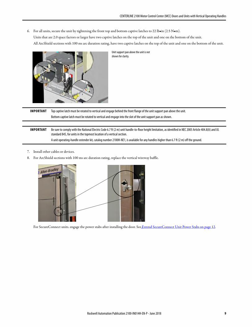
6. For all units, secure the unit by tightening the front top and bottom captive latches to 22 lb•in (2.5 N•m).
Units that are 2.0 space factors or larger have two captive latches on the top of the unit and one on the bottom of the unit.
All ArcShield sections with 100 ms arc duration rating, have two captive latches on the top of the unit and one on the bottom of the unit.
7. Install other cables or devices.
8. For ArcShield sections with 100 ms arc duration rating, replace the vertical wireway baffle.
For SecureConnect units. engage the power stabs after installing the door. See Extend SecureConnect Unit Power Stabs on page 12.
IMPORTANT Top captive latch must be rotated to vertical and engage behind the front flange of the unit support pan above the unit.
Bottom captive latch must be rotated to vertical and engage into the slot of the unit support pan as shown.
IMPORTANT Be sure to comply with the National Electric Code 6.7 ft (2 m) unit handle-to-floor height limitation, as identified in NEC 2005 Article 404.8(A) and UL standard 845, for units in the topmost location of a vertical section.
A unit operating-handle extender kit, catalog number 2100H-NE1, is available for any handles higher than 6.7 ft (2 m) off the ground.
Unit support pan above the unit is not shown for clarity.
Rockwell Automation Publication 2100-IN014H-EN-P - June 2018 9
CENTERLINE 2100 Motor Control Center (MCC) Doors and Units with Vertical Operating Handles
Install the DoorFollow this procedure to install the door.
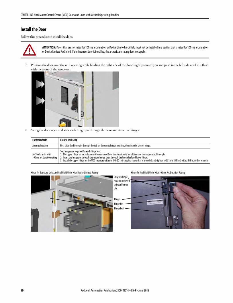
1. Position the door over the unit opening while holding the right side of the door slightly toward you and push in the left side until it is flush with the front of the structure.
2. Swing the door open and slide each hinge pin through the door and structure hinges.
ATTENTION: Doors that are not rated for 100 ms arc duration or Device Limited ArcShield must not be installed in a section that is rated for 100 ms arc duration or Device Limited ArcShield. If the incorrect door is installed, the arc resistant rating does not apply.
For Units With Follow This Step
A control station First slide the hinge pin through the tab on the control station wiring, then into the closest hinge.
ArcShield units with 100 ms arc duration rating
Two hinges are required for each hinge leaf. 1. The upper hinge on each door must be removed from the structure to install/remove the uppermost hinge pin.2. Insert the hinge pin through the upper hinge, then through the hinge leaf and lower hinge.3. Install the upper hinge on the MCC structure with the 1/4-20 self-tapping screw that is provided and tighten to 55 lb•in (6 N•m) with a 3/8 in. socket wrench.
Only top hinge must be removed to install hinge pin.
Hinge
Hinge Pin
Hinge Leaf
Hinge for Standard Units and ArcShield Units with Device Limited Rating Hinge for ArcShield Units with 100 ms Arc Duration Rating
10 Rockwell Automation Publication 2100-IN014H-EN-P - June 2018
CENTERLINE 2100 Motor Control Center (MCC) Doors and Units with Vertical Operating Handles
3. If a control station is present, place it through the door cutout and tighten the captive screws.
4. If swing-out latch brackets are present, rotate the movable portion of the swing-out latch bracket in the counter-clockwise direction unit it stops.
5. Close the door and secure the latch.
See MCC instructions, publication 2100-IN012, for more information on proper door latch orientations.
For Follow This Step
Non-arc resistant latches Turn each door latch 1/4 turn until the latch catches onto the unit support pan or structure and holds the door closed.
Units that are equipped with arc resistant door latches Orient the slot of the latch so that it is horizontal, then push in the latch and rotate 1/4 turn.
TIP Latches can require a screwdriver to open and close.
TIP When properly latched, the slots on the arc resistant latches are vertical and the latch springs are compressed. The spacing of the spring coils is decreased.
Latch
Arc Resistant Latch
Uncompressed Spring - Unlatched
Compressed Spring - Latched
Rockwell Automation Publication 2100-IN014H-EN-P - June 2018 11
CENTERLINE 2100 Motor Control Center (MCC) Doors and Units with Vertical Operating Handles
Extend SecureConnect Unit Power StabsFollow this procedure to extend the SecureConnect unit power stabs.
1. Verify that the disconnect handle is in the OFF/O position.
2. Insert 1/4 in. hex tool into shaft port and rotate tool clockwise.
The indicator next to the disconnect handle changes from green to red.
Indicator
Shaft Port
12 Rockwell Automation Publication 2100-IN014H-EN-P - June 2018
CENTERLINE 2100 Motor Control Center (MCC) Doors and Units with Vertical Operating Handles
Additional ResourcesThese documents contain more information about related products from Rockwell Automation.
You can view or download publications at http://www.rockwellautomation.com/literature/. To order paper copies of technical documentation, contact your local Allen-Bradley distributor or Rockwell Automation sales representative.
Resource Description
CENTERLINE 2100 Low Voltage Motor Control Centers Instruction Manual, publication 2100-IN012 Provides general instructions for MCC Units.
CENTERLINE 2100 Motor Control Center Units with Horizontal Operating Handles, publication 2100-IN060 Provides information on the installation of units with horizontal operating handles.
Safety Guidelines for the Application, Installation, and Maintenance of Solid-state Control Installation Instructions, publication SGI-1.1 Provides safety guidelines for the application, installation, and maintenance of solid-state control.
Industrial Automation Wiring and Grounding Guidelines, publication 1770-4.1 Provides general guidelines for installing a Rockwell Automation® industrial system.
Product Certifications website, http://www.rockwellautomation.com/products/certification Provides declarations of conformity, certificates, and other certification details.
Rockwell Automation Publication 2100-IN014H-EN-P - June 2018 13
Rockwell Automation SupportUse the following resources to access support information.
Documentation FeedbackYour comments will help us serve your documentation needs better. If you have any suggestions on how to improve this document, complete the How Are We Doing? form at http://literature.rockwellautomation.com/idc/groups/literature/documents/du/ra-du002_-en-e.pdf.
Technical Support Center Knowledgebase Articles, How-to Videos, FAQs, Chat, User Forums, and Product Notification Updates. https://rockwellautomation.custhelp.com/
Local Technical Support Phone Numbers Locate the phone number for your country. http://www.rockwellautomation.com/global/support/get-support-now.page
Direct Dial Codes Find the Direct Dial Code for your product. Use the code to route your call directly to a technical support engineer. http://www.rockwellautomation.com/global/support/direct-dial.page
Literature Library Installation Instructions, Manuals, Brochures, and Technical Data. http://www.rockwellautomation.com/global/literature-library/overview.page
Product Compatibility and Download Center (PCDC)
Get help determining how products interact, check features and capabilities, and find associated firmware. http://www.rockwellautomation.com/global/support/pcdc.page
Allen-Bradley, ArcShield, CENTERLINE, Rockwell Automation, Rockwell Software, and SecureConnect are trademarks of Rockwell Automation, Inc.
Trademarks not belonging to Rockwell Automation are property of their respective companies.
Rockwell Otomasyon Ticaret A.Ş., Kar Plaza İş Merkezi E Blok Kat:6 34752 İçerenköy, İstanbul, Tel: +90 (216) 5698400
Rockwell Automation maintains current product environmental information on its website athttp://www.rockwellautomation.com/rockwellautomation/about-us/sustainability-ethics/product-environmental-compliance.page.


![PROCUREMENT SPECIFICATION - Rockwell Automation · [PROJECT NUMBER] [PROJECT NAME] [DATE] [PROJECT LOCATION] CENTERLINE 2100 Motor Control Centers Rockwell Automation 2100-SR007K-EN-E](https://static.documents.pub/doc/80x56/5e15ff04c0b8380fd7152cb0/procurement-specification-rockwell-automation-project-number-project-name.jpg)


