38
CENTERLINE ® 2500 DeviceNet ™ Motor Control Centers Technical Data

CENTERLINE® 2500
DeviceNet™ Motor Control Centers
Technical Data

Important User Information Solid state equipment has operational characteristics differing from those of electromechanical equipment. Safety Guidelines for the Application, Installation and Maintenance of Solid State Controls (Publication SGI-1.1 available from your local Rockwell Automation sales office or online at http://www.ab.com/manuals/gi) describes some important differences between solid state equipment and hard-wired electromechanical devices. Because of this difference, and also because of the wide variety of uses for solid state equipment, all persons responsible for applying this equipment must satisfy themselves that each intended application of this equipment is acceptable.In no event will Rockwell Automation, Inc. be responsible or liable for indirect or consequential damages resulting from the use or application of this equipment.The examples and diagrams in this manual are included solely for illustrative purposes. Because of the many variables and requirements associated with any particular installation, Rockwell Automation, Inc. cannot assume responsibility or liability for actual use based on the examples and diagrams.No patent liability is assumed by Rockwell Automation, Inc. with respect to use of information, circuits, equipment, or software described in this manual.Reproduction of the contents of this manual, in whole or in part, without written permission of Rockwell Automation, Inc. is prohibited.
Throughout this manual, when necessary we use notes to make you aware of safety considerations.
WARNINGIdentifies information about practices or circumstances that can cause an explosion in a hazardous environment, which may lead to personal injury or death, property damage, or economic loss.
IMPORTANT Identifies information that is critical for successful application and understanding of the product.
ATTENTION Identifies information about practices or circumstances that can lead to personal injury or death, property damage, or economic loss. Attentions help you:• identify a hazard• avoid a hazard• recognize the consequence
SHOCK HAZARD Labels may be located on or inside the equipment (e.g. drive or motor) to alert people that dangerous voltage may be present.
BURN HAZARD Labels may be located on or inside the equipment (e.g. drive or motor) to alert people that surfaces may be dangerous temperatures.

i Publication 2500-TD002A-EN-P—May 2006
Table of Contents
Important User Information . . . . . . . . . . . . . . . . . . . Inside Front Cover
Overview. . . . . . . . . . . . . . . . . . . . . . . . . . . . . . . . . . . . . . . . . . . . . . . . . . 2DeviceNet. . . . . . . . . . . . . . . . . . . . . . . . . . . . . . . . . . . . . . . . . . . . . . . . . 2DeviceNet in MCCs . . . . . . . . . . . . . . . . . . . . . . . . . . . . . . . . . . . . . . . . . 2System Architecture . . . . . . . . . . . . . . . . . . . . . . . . . . . . . . . . . . . . . . . . . 2
Node Count . . . . . . . . . . . . . . . . . . . . . . . . . . . . . . . . . . . . . . . . . . . . 3Cable Length Limitations . . . . . . . . . . . . . . . . . . . . . . . . . . . . . . . . . 3Trunk Cable Routing . . . . . . . . . . . . . . . . . . . . . . . . . . . . . . . . . . . . . 4Terminating Resistors . . . . . . . . . . . . . . . . . . . . . . . . . . . . . . . . . . . . 8Installing Terminating Resistor Guidelines . . . . . . . . . . . . . . . . . . 11Installing Terminating Resistor Examples . . . . . . . . . . . . . . . . . . . 12
Splicing DeviceNet Communication Cables inMotor Control Centers . . . . . . . . . . . . . . . . . . . . . . . . . . . . . . . . . . . . 19
DeviceNet Power Supply. . . . . . . . . . . . . . . . . . . . . . . . . . . . . . . . . . . . 21Connecting Power Supplies—
Remote or in the MCC Line-Up. . . . . . . . . . . . . . . . . . . . . . . . . . 21Network Power Supply and the Protective Earth Circuit . . . . . . . 22Connecting Two Power Supplies . . . . . . . . . . . . . . . . . . . . . . . . . . 23
Start-Up and Training Aids . . . . . . . . . . . . . . . . . . . . . . . . . . . . . . . . . . 24IntelliCENTER MCC Design, Start-Up and Training Course . . . 24Field Support Kit for DeviceNet MCCs. . . . . . . . . . . . . . . . . . . . . 25Training Cases . . . . . . . . . . . . . . . . . . . . . . . . . . . . . . . . . . . . . . . . . 28
System Design Installation Checklist . . . . . . . . . . . . . . . . . . . . . . . . . . 29DeviceNet Software Installation Checklist . . . . . . . . . . . . . . . . . . . . . . 29How to Find Electronic Data Sheets (EDS). . . . . . . . . . . . . . . . . . . . . 31
Background . . . . . . . . . . . . . . . . . . . . . . . . . . . . . . . . . . . . . . . . . . . 31Definition of EDS Files. . . . . . . . . . . . . . . . . . . . . . . . . . . . . . . . . . 31Necessary EDS Files . . . . . . . . . . . . . . . . . . . . . . . . . . . . . . . . . . . . 31Installing EDS Files . . . . . . . . . . . . . . . . . . . . . . . . . . . . . . . . . . . . . 31Finding EDS Files for Other Devices . . . . . . . . . . . . . . . . . . . . . . 32Uploading EDS Files from the Device. . . . . . . . . . . . . . . . . . . . . . 32
Rockwell Automation Support . . . . . . . . . . . . . . . . . Inside Back CoverInstallation Assistance . . . . . . . . . . . . . . . . . . . . . Inside Back CoverNew Product Satisfaction Return . . . . . . . . . . . . Inside Back Cover

Publication 2500-TD002A-EN-P—May 2006
ii

1 Publication 2500-TD002A-EN-P—May 2006
DeviceNet™ Motor Control Centers
Table A Publications
Table B Websites
Table C Technical Support
Title Description Publication Number
CENTERLINE®
2500 Motor Control Centers Product Profile 2500-PP001x-EN-P*
IntelliCENTER®
Software Product Profile 2100-PP017x-EN-P*
IntelliCENTER Software User Guide User Manual 2100-UM002x-EN-P*
Integrated, Intelligent Motor Control Centers White Paper 2100-WP001x-EN-P*
Joining and Splicing Columns Instructions 2500-IN004x-EN-P
DeviceNet Product Overview System Overview DN-2.5
DeviceNet Selection Guide Selection Guide DNET-SG001x-EN-P*
DeviceNet Media Design Installation Guide User Manual DNET-UM072x-EN-P
KwikLink Radiated Immunity Testing White Paper 1485-WP001x-US-P*
KwikLink Connection System Brochure Brochure 1485-CG001x-EN-P
* x is a placeholder for the revision letter of the publication. When referencing publication via The Literature Library (www.rockwellautomation.com/literature) always use the latest revision available.
Topic Internet Web Address
IntelliCENTER http://www.ab.com/intellicenter
Motor Control Centers http://www.ab.com/mcc
Electronic Publications http://www.rockwellautomation.com/literature
Ordering Publications http://www.rockwellautomation.com/dox
DeviceNet (Allen-Bradley) http://www.ab.com/networks
Electronic Data Sheet (EDS) Files http://www.ab.com/networks/eds
Open DeviceNet Vendor Association (ODVA) http://www.odva.org
Type of support Access at
Telephone 440.646.5800
Fax 414.382.0505
E-mail [email protected]
Internet website http://www.ab.com/mcc

Publication 2500-TD002A-EN-P—May 2006
2 DeviceNet™ Motor Control Centers
Overview This document describes cable system construction and components associated with a DeviceNet network that is factory installed in CENTERLINE® 2500 and IntelliCENTER® motor control centers (MCCs).
DeviceNet DeviceNet is a low-cost communication link to connect industrial devices (such as limit switches, photoelectric sensors, motor starters, push buttons, variable frequency drives, and operator interfaces) to a network and eliminate time-consuming and costly hardwiring.
DeviceNet is a simple, open networking solution based on the producer/consumer model, the latest in network technology. This technology allows for real-time control, data exchange, configuration capabilities, and collection of data at regular intervals or on demand. The network specifications and protocol are open—managed by the Open DeviceNet Vendor Association (ODVA)—meaning that vendors are not required to purchase hardware, software, or licensing rights to connect devices to a system. This has resulted in over 300 vendors offering DeviceNet products and over a half million installed nodes worldwide.
DeviceNet in MCCs DeviceNet is ideally suited for MCC applications with respect to cost and performance. This document details the applications of DeviceNet in MCCs, including cable system construction and common DeviceNet components.
System Architecture When designing DeviceNet systems, it is necessary to consider the following factors:
• Node Count• Cable Type and Lengths• Terminating Resistors with Internal and External Devices
ATTENTION Before performing any service or maintenance activities on MCC columns, disconnect all power sources.
Follow local codes and guidelines in addition to the requirements of EN 50110.

Publication 2500-TD002A-EN-P—May 2006
DeviceNet™ Motor Control Centers 3
Node Count
DeviceNet can accommodate 64 nodes. Typically, three nodes are reserved for the scanner, PC and a new device.
Node count is also affected by performance needs and future expandability. To ensure this, use following the table to set node count guidelines.
Cable Length Limitations
Cable lengths are calculated for two types of types of cables: trunk and drop. Trunk cable consists of all cable located directly between terminating resistors. All other cable is drop cable.
Baud Rate DeviceNet MCC IntelliCENTER MCC
125 kbps 50 Not Supported
250 kbps 50 35
500 kbps(1)
(1)To achieve maximum performance of an IntelliCENTER MCC, 500 kbps should be used.
50 50
Baud Rate Maximum Trunk Cable Length Maximum Drop Cable Length(2)
(2)No single drop can exceed 6 m in length
125 kbps 420 m 156 m
250 kbps 200 m 78 m
500 kbps(1)
(1)To achieve maximum performance of an IntelliCENTER MCC, 500 kbps should be used.
75 m 39 m

Publication 2500-TD002A-EN-P—May 2006
4 DeviceNet™ Motor Control Centers
Trunk Cable Routing
Figure 1 Typical Single MCC Column
The DeviceNet trunk line is routed through the control and network wireway and top horizontal wireway of the MCC. Trunk lines are routed behind barriers that isolate the cable from the unit space and wireways to help prevent accidental damage during MCC installation. Up to 24 DeviceNet ports can be provided in the control and network wireway.
The trunk line terminates with a receptacle on the left side of the leftmost column and right side of the rightmost column in a shipping block. The receptacles are accessible by removing the top horizontal wireway covers. Connection is made to DeviceNet when a unit is in the Connected or Test position.
The DeviceNet drop line will connect each DeviceNet component in a MCC unit to a DeviceNet port located in the control and network wireway. The addition or removal of a unit from the DeviceNet system does not interrupt the operation of other units in the system.
Linking Receptacle
3-Phase Horizontal Power Bus
Trunk line in the control and network wireway.
DeviceNet ports are supplied for each required unit
Linking Receptacle

Publication 2500-TD002A-EN-P—May 2006
DeviceNet™ Motor Control Centers 5
Figure 2 Typical Two-Column Shipping Block
Determining Cable Lengths
To help determine cable lengths for your application, each MCC is shipped with documentation identifying the trunk and drop length used within the MCC. (See Figure 3)
Cable lengths can also be calculated. See the guidelines for Calculating Cable Lengths on Page -6.
Figure 3 DeviceNet Network Specifications
Top Horizontal Wireway
Linking Receptacles
3-Phase Horizontal Power Bus
DeviceNet NETWORK SPECIFICATIONS
NETWORK NUMBER: 01BAUD RATE: 500 kbpsTOTAL NUMBER OF NODES: 16
CURRENT DRAW: 2.115 AMPERESCUMULATIVE DROP LENGTH: 12.3 mCUMULATIVE TRUNK LENGTH: 28.5 m
NOTE – The cumulative length of the trunk and drop cables determine the maximumbaud rate of the DeviceNet system.
– 500 kbps if the cumulative trunk length is less than 75 m ANDthe cumulative drop length is less than 39 m.
– 250 kbps if the cumulative trunk length is less than 200 m ANDthe cumulative drop length is less than 78 m.
– 125 kbps if the cumulative trunk length is less than 420 m ANDthe cumulative drop length is less than 156 m.

Publication 2500-TD002A-EN-P—May 2006
6 DeviceNet™ Motor Control Centers
Calculating Cable Lengths
Calculate trunk and drop cable lengths based on the following guidelines.
Trunk Cable Length
• Measure trunk cable external to the MCC• Use Table D to estimate the length of trunk cable inside the MCC.
NOTE: Lengths include the jumper used to splice DeviceNet columns in a network.
Table D Trunk Cable Within the MCC
Drop Cable Length
• Measure drop cable external to the MCC• Measure each drop cable to individual units OR
– estimate 0.75 m for each withdrawable unit in the MCC lineup– estimate 1.5 m for each fixed unit in the MCC lineup
Column Width Trunk LengthColumns with
Withdrawable Units
Trunk LengthColumns with Fixed
(Frame-Mounted) Units
700 mm 5.0 m 0.7 m
800 mm 5.1 m 0.8 m
900 mm 5.2 m 0.9 m
1000 mm 5.3 m 1.0 m
Publication 2500-TD002A-EN-P—May 2006
DeviceNet™ Motor Control Centers 7
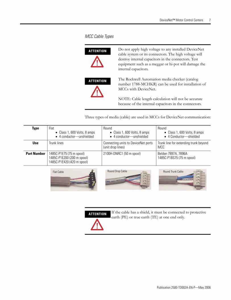
MCC Cable Types
Three types of media (cable) are used in MCCs for DeviceNet communication:
ATTENTION Do not apply high voltage to any installed DeviceNet cable system or its connectors. The high voltage will destroy internal capacitors in the connectors. Test equipment such as a meggar or hi-pot will damage the internal capacitors.
ATTENTION The Rockwell Automation media checker (catalog number 1788-MCHKR) can be used for installation of MCCs with DeviceNet.
NOTE: Cable length calculation will not be accurate because of the internal capacitors in the connectors.
Type Flat• Class 1, 600 Volts, 8 amps• 4 conductor—unshielded
Round• Class 1, 600 Volts, 8 amps• 4 conductor—unshielded
Round• Class 1, 600 Volts, 8 amps • 4 Conductor—shielded
Use Trunk lines Connecting units to DeviceNet ports (unit drop lines)
Trunk line for extending trunk beyond MCC
Part Number 1485C-P1E75 (75 m spool)1485C-P1E200 (200 m spool)1485C-P1E420 (420 m spool)
2100H-DNRC1 (50 m spool) Belden 7897A, 7896A1485C-P1BS75 (75 m spool)
Flat Cable Round Drop Cable Round Trunk Cable
ATTENTION If the cable has a shield, it must be connected to protective earth (PE) or true earth (TE) at one end only.
Publication 2500-TD002A-EN-P—May 2006
8 DeviceNet™ Motor Control Centers
Terminating Resistors
Terminating resistors are necessary at the ends of trunk lines to reduce reflections of the communication signals on the network. The DeviceNet network will operate correctly only when there are exactly two terminating resistors, one at each end of the trunk line. Terminating resistors must be equal to 121 ohms 1%, 1/4W, metal film (terminating resistor part number 1485A-C2).
MCC line-ups ship with a clear bag containing two 5-terminal plug connectors with terminating resistors installed and two DeviceNet splitter connectors (kit part number 2100H-DNTR1). The resistors are inserted in the second terminal from each end (connected to the white and blue conductors) of both plugs (See Figure 4). The DeviceNet splitter connector is used to plug two DeviceNet connectors into one port.
IMPORTANT It is not recommended to use both Class 1- and Class 2-rated cables within the same DeviceNet system. These two cable types are not compatible because the following properties are different:
• Insulation class• Overcurrent protection requirements• Network transmission
Using Class 1- and Class 2-rated cables within the same DeviceNet system can result in application, code, and communication problems.
ATTENTION Before performing any service or maintenance activities on MCC columns, disconnect all power sources.
Follow local codes and guidelines in addition to the requirements of EN 50110.

Publication 2500-TD002A-EN-P—May 2006
DeviceNet™ Motor Control Centers 9
Figure 4 Five-Terminal Plug Connector With Jack Screws (P/N 22112-215-01)
The bag is shipped in the top horizontal wireway (identified by a label on the horizontal wireway cover of this column). (See Figure 5).
Jack Screw Jack Screw
Terminating Resistor
Black
BlueWhite
Red
Shield wire, connect shield to PE at one end only

Publication 2500-TD002A-EN-P—May 2006
10 DeviceNet™ Motor Control Centers
Figure 5 DeviceNet Terminating Resistor Kit
Terminating Resistor KitPart # 2100H-DNTR1

Publication 2500-TD002A-EN-P—May 2006
DeviceNet™ Motor Control Centers 11
Guidelines for Installing Terminating Resistors
When installing terminating resistors, apply the following two rules:
1. Use only two terminating resistors in any network.
2. Install terminating resistors at the ends (communication and/or physical) of the trunk line.
Incorrect placement of terminating resistors and/or using more than two will cause improper network operation and result in communication losses.
1. Locate the terminating resistor kit. Terminating resistor kits are shipped in the top horizontal wireway. A white label indicates the location of the kit (See Figure 5).
2. Remove the top horizontal wireway cover from each column in the network.
3. Plug the first terminating resistor into the left port in the top horizontal wireway of the leftmost column in the network. Torque the connector screws to 0.55 N-m.
4. Plug the second terminating resistor into the right port in the top horizontal wireway of the rightmost column of the network. Torque the connector screws to 0.55 N-m.

Publication 2500-TD002A-EN-P—May 2006
12 DeviceNet™ Motor Control Centers
Installing Terminating Resistor Examples
When installing resistors, the type of DeviceNet Architecture must first be determined. There are two types of architecture.
• All devices internal to the MCC• Devices internal and external to the MCC
Installing Terminating Resistors with all Devices Internal to the MCC
This is the simplest form of DeviceNet architecture. Since all devices are internal to the MCC, special wiring is not needed.
Figure 6, Figure 7 and Figure 8 show typical designs and placements of terminating resistors.
Figure 6 shows a MCC with a DeviceNet scanner located in a fixed column. Wireway plugs are not present in this column.
Figure 6 DeviceNet Scanner Installed in a Fixed Unit (One Network)
DeviceNet Scanner

Publication 2500-TD002A-EN-P—May 2006
DeviceNet™ Motor Control Centers 13
Figure 7 shows a typical MCC with the DeviceNet scanner located in a plug-in unit.
Figure 7 DeviceNet Scanner Installed in a Plug-In Unit (One Network)
DeviceNet Scanner

Publication 2500-TD002A-EN-P—May 2006
14 DeviceNet™ Motor Control Centers
Figure 8 shows a MCC with two DeviceNet scanners and two different networks. When a MCC has two networks, four terminating resistors are needed.
Figure 8 DeviceNet Scanner Installed in a Plug-In Unit (Two Networks)
DeviceNet Scanners
Do not splice trunk lines between two separate DeviceNet networks
First DeviceNet Network Second DeviceNet Network

Publication 2500-TD002A-EN-P—May 2006
DeviceNet™ Motor Control Centers 15
Installing Termination Resistors with Devices Internal and External to the MCC
This architecture is more complex, because external devices must be wired to the internal network of the MCC. Careful attention must be given to the type of cable selected and the method of installation.
Figure 9, Figure 10, Figure 11 and Figure 12 show where to place the terminating resistors when external devices are used.
Figure 9 has a DeviceNet scanner remote from the MCC. In this example the cable from the scanner to the MCC top horizontal wireway port is an extension of the DeviceNet trunk line.
Figure 9 Remote DeviceNet Scanner (One Network)
DeviceNet Scanner

Publication 2500-TD002A-EN-P—May 2006
16 DeviceNet™ Motor Control Centers
Figure 10 shows a single MCC with two DeviceNet networks and two remote scanners. When a MCC has two networks, four terminating resistors are needed. In this example the cable from the scanner to the MCC top horizontal wireway port is an extension of the DeviceNet trunk.
Figure 10 Remote DeviceNet Scanner (Two Networks)
DeviceNet Scanners
Do not splice trunk lines between two separate DeviceNet networks
Second DeviceNet NetworkFirst DeviceNet Network
Publication 2500-TD002A-EN-P—May 2006
DeviceNet™ Motor Control Centers 17
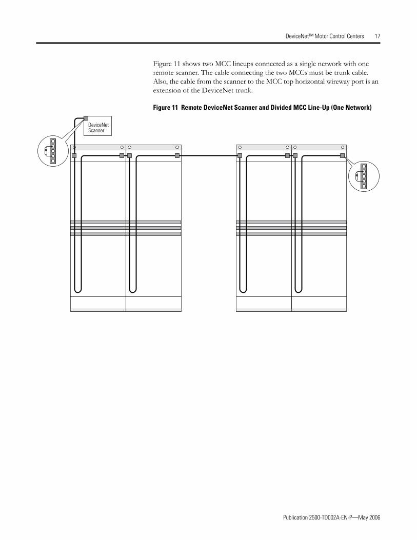
Figure 11 shows two MCC lineups connected as a single network with one remote scanner. The cable connecting the two MCCs must be trunk cable. Also, the cable from the scanner to the MCC top horizontal wireway port is an extension of the DeviceNet trunk.
Figure 11 Remote DeviceNet Scanner and Divided MCC Line-Up (One Network)
DeviceNet Scanner

Publication 2500-TD002A-EN-P—May 2006
18 DeviceNet™ Motor Control Centers
Figure 12 shows a remote scanner and a remote device. This is a single network. All cable external to the MCC must be trunk cable.
Figure 12 Remote DeviceNet Scanner with Remote Device (One Network)
DeviceNet Scanner
PowerFlex Drive

Publication 2500-TD002A-EN-P—May 2006
DeviceNet™ Motor Control Centers 19
NOTE: If the terminating resistor is being placed in a remote device, it will be necessary to remove the resistor from the supplied plug and install it in an open row of terminals on a ten-terminal plug.
Splicing DeviceNet Communication Cables in Motor Control Centers
General
This section describes the recommended procedure for splicing DeviceNet communication cables (trunk lines) in MCCs. It must be used in conjunction with publication 2500-IN004x-EN-P, Joining and Splicing Vertical Columns. Cable can be spliced to the leftmost or rightmost column of a MCC lineup.
Terminating Resistor
Ten-terminal plug connector with terminating resistor plugged into a DeviceNet module
Shield wire if used
Terminating resistor position in open row of terminals on a ten-terminal plug connector

Publication 2500-TD002A-EN-P—May 2006
20 DeviceNet™ Motor Control Centers
Procedure
1. After the terminating resistors have been installed, DeviceNet cables in each column of the network must be spliced together.
2. Locate the DeviceNet splicing cable in the top horizontal wireway. One end of the splicing cable will be plugged into the right DeviceNet port in the column to the left of the splice.
3. Route the cable through the top horizontal wireway into the column to the right of the splice.
4. Plug the free end of the DeviceNet splicing cable into the left port in the top horizontal wireway of the column to the right of the splice.
5. Torque connector screws on the splicing cable plugs to 0.55 N-m.
6. Ensure the horizontal wireway is free of tools and debris.
7. Replace horizontal wireway covers.
8. When new columns are added, complete the following design calculations:• Check the total number of nodes. See System Architecture beginning
on page 2. If the number of nodes exceeds the guidelines, add a new network.
• Recalculate the total power consumption. If it exceeds 8 A, add an additional power supply. A maximum of 7.2 A is preferred to allow for a 10% margin.
• Verify the cumulative trunk length. See System Architecture.• Verify the cumulative drop length. See System Architecture.

Publication 2500-TD002A-EN-P—May 2006
DeviceNet™ Motor Control Centers 21
DeviceNet Power Supply
A power supply unit that meets DeviceNet requirements can be supplied with the MCC. A cable connects the output of the power supply to a DeviceNet port in the control and network wireway. This cable is already connected when the power supply unit ships installed in the MCC. Redundant configurations are also available.
Remote power supplies should meet the following requirements, per ODVA:
• Rated 24 V DC (±1%)• Rise time of less than 250 milliseconds to within 5% of 24V DC at full
load of 8 A• Current limit protection of 8 amps continuous and 10 amps for the first
250 ms• Sized correctly to provide each device with its required power—each
device typically requires 90–165 mA • Derated for temperature using the manufacturer’s guidelines
Connecting Power Supplies—Remote or in the MCC Line-Up
Connecting power supplies according to these guidelines will minimize voltage drops in the DeviceNet system and ensure proper supply voltage to system devices. Refer to the Media Design Installation Guide, DNET-UM072x-EN-P, for detailed connecting instructions.
IMPORTANT The DeviceNet cable system requires a 24V DC power source to operate. The power supply must be DeviceNet compatible as specified in the ODVA requirements
IMPORTANT: Power supplies that do not satisfy both points listed above can result in damage to the DeviceNet signal and components, as well as failure to comply with local codes and inspection.

Publication 2500-TD002A-EN-P—May 2006
22 DeviceNet™ Motor Control Centers
Network Power Supply and the Protective Earth Circuit
The DeviceNet cable must be connected to the PE circuit at only one location. The ideal choice is at the power supply. Connect the power supply and 24 V DC common (black wire) to the PE circuit using #8 AWG wire.
Best PE Practice
• If the power supply comes installed in the MCC, the black 24 V DC common terminal is connected to the PE within the unit. To improve the connection, use #8 AWG green wire and ground the black 24V DC common terminal to a very stable PE external to the MCC (or to an optional true earth (TE) connection inside the MCC).
• If the power supply is external, the same recommendations apply.

Publication 2500-TD002A-EN-P—May 2006
DeviceNet™ Motor Control Centers 23
Connecting Two Power Supplies
An additional 24 V DC Class 1 power supply must be installed for MCC line-ups with more than 14 columns. When using two supplies, the red conductor between the power supplies must be broken. Locate a linking connector between columns and disconnect the red conductor (See Figure 13).
Connect only ONE of the two power supplies to the PE.
Figure 13 Connecting Two Power Supplies
Position each power supply to ensure that it feeds a maximum of seven columns to the left or right (refer to the sample line-up below).
MCC line-ups with more than 14 columns could exceed the 75 m trunk length limit to support 500 kbps communications. When the trunk length exceeds this limit, 250 kbps communications should be specified.
Power SupplyPower Supply
Red V+
White CAN_H
Blue CAN_L
Black V- (common)
BREAK
Power SupplyPower Supply
MCC Line-Up With More Than 14 Columns
Break Red Conductor

Publication 2500-TD002A-EN-P—May 2006
24 DeviceNet™ Motor Control Centers
Start-Up and Training Aids IntelliCENTER MCC Design, Start-Up and Training Course
Course Description
This course provides the concepts, knowledge and tools necessary to design, specify, install, troubleshoot and use an IntelliCENTER MCC or DeviceNet MCC.
Content
• Basics of communication and Rockwell Automation networks• Control and communication architecture overview with sample
architecture problems solved in class (selecting networks, network devices, network speeds, etc.)
• DeviceNet MCC structure, units, wiring and technical details for low voltage and medium voltage MCCs
• Demonstration of software associated with DeviceNet MCCs (RSLinx and RSNetworkx for DeviceNet)
• Necessary steps for a successful start-up including installing EDS files• Maintenance issues, such as adding MCC units to IntelliCENTER
MCCs, replacement of DeviceNet devices and reommended tools• Network configuration, mapping of scanners and PLC programming in
a DeviceNet MCC system, including hands-on exercises with a ControlLogix system
Who Should Attend
This course is intended for control engineers, electrical technicians and system integrators who will be involved in designing, installing and using IntelliCENTER/DeviceNet MCCs.
Prerequisite
• Familiarity with Windows and PLC programming
Publication 2500-TD002A-EN-P—May 2006
DeviceNet™ Motor Control Centers 25
Topical Outline
Course Dates and Prices
Refer to www.rockwellautomation.com/trainingSelect course CCI 105.
Field Support Kit for DeviceNet MCCs
The Allen-Bradley DeviceNet and IntelliCENTER MCCs provide users with a DeviceNet network that is wired, commissioned and tested, resulting in a true plug-and-play integrated solution. As with any control system, a successful installation requires the proper tools. This kit includes an assortment of DeviceNet-related components that will prove helpful for:
• Starting up a DeviceNet system• Commission DeviceNet nodes (setting baud rate and node number)• Testing DeviceNet devices• Training on DeviceNet
• Basics of DeviceNet• NetLinx overview• RSLinx and RSNetworkx • DeviceNet wiring• Receiving and installing
DeviceNet MCC columns• IntelliCENTER software
configuration• Installing and registering EDS
files• Adding MCC units to
IntelliCENTER MCCs
• Replacement of DeviceNet devices
• Hands-on IntelliCENTER lab• Support resources• Mapping scanners -
introduction, examples, hands-on
• Programming PLCs connected to DeviceNet - introduction, examples, hands-on with a ControlLogix system

Publication 2500-TD002A-EN-P—May 2006
26 DeviceNet™ Motor Control Centers
The kit includes a mini network, a DeviceNet configurator tool and assorted components.
Mini Network
• Trunk line with three DeviceNet ports and terminating resistors
• 3 meter patch cable• 0.5 meter patch cable• 24 V DC power supply
DeviceNet Configurator Tool
• DeviceView Handheld Configurator (193-PCT) with 1 meter cable
Assorted Components for DeviceNet
• (5) terminating resistors• (10) 5-terminal plug connectors• (5) 10-terminal plug connectors• (2) 5-terminal male connectors• 3 meter Round Class 1 DeviceNet
cable • Narrow-tip screwdriver for
DeviceNet connectors• DeviceNet Y-Header

Publication 2500-TD002A-EN-P—May 2006
DeviceNet™ Motor Control Centers 27
Applications
Mini-network wall plug (with male connector)
DeviceNet Configurator (or laptop computer) Configurator
cable
10-terminal plug with terminating resistor plugged into a port
0.5 meter or 3 meter patch cable (with connectors)
10-terminal plug with terminating resistor
Mini Network
Connecting to a DeviceNet MCC
3 meter patch cable (with connections)
Laptop computer with 1784-PCD DeviceNet card and cable (not included)
Mini-network wall plug power supply (with male connector)
E3 Electronic Overload Relay (not included)
Configurator cable
0.5 meter patch cable (with connectors)
DeviceNet ConfiguratorInternal terminator resistor programmed “IN”Y-Header (splitter)
Stand Alone Configurator Tool
DeviceNet Device (not included)

Publication 2500-TD002A-EN-P—May 2006
28 DeviceNet™ Motor Control Centers
The following items are suggested for IntelliCENTER and DeviceNet MCC installation and maintenance:
• Field Support kit for DeviceNet MCCs, 2100H-DFSK1• Hand tools—high-quality side-cutter, needle nose pliers, wire stripper• Short length of Class 1, 8 A round adapter cable with five-terminal
receptacle on each end• Three meter personal computer (PC) cable with five-terminal plug on
each end—part number 2100H-ICPC120• Digital multi-meter—Fluke 79 or equivalent• ODVA DeviceNet monitor — order form available at
http://www.ab.com/intellicenter/instructions or contact your local Rockwell Automation representative
• Laptop personal computer with the following software:– RS Networx for DeviceNet– RS Linx– ControlFlash update software– RS Logix 5 for PLC/5– RS Logix 500 for SLC and MicroLogix– RS Logix 5000 for ControlLogix– IntelliCENTER software
Training Cases
For the ultimate in-house training - two styles of IntelliCENTER training cases are available
2-Unit Training Case
• Starter with E3 electronic overload relay
• Starter with DeviceNet starter auxiliary
• Motor• Load
1-Unit Training Case
• Starter with E3 electronic overload relay
• Load for each phase

Publication 2500-TD002A-EN-P—May 2006
DeviceNet™ Motor Control Centers 29
System Design Installation Checklist
When installing a DeviceNet MCC, use the following checklist before applying power to the network:
• Number of nodes does not exceed 64, with three nodes typically reserved for scanner (node 00), PC (node 62), and new device (node 63)
• Individual drop lengths do not exceed 6 m• Cumulative drop length does not exceed the desired network baud rate
limit: 39 m at 500 kbps, 78 m at 250 kbps or 156 m at 125 kbps• Total trunk length does not exceed the maximum allowable per the
network baud rate: 75 m at 500 kbps, 200 m at 250 kbps, or 420 m at 125 kbps
NOTE: For IntelliCENTER, 500 kbps provides optimum performance (250 kbps may be used, but is not recommended).
• Verify that all devices are programmed to the same baud rate. Autobaud can be used for each device. This allows the scanner to set the baud rate for the entire system
• Verify that terminating resistors are in place at the trunk line terminations and measure for proper resistance (121 ohms, 1/4 W, 1%, metal film)
• Verify that the power supply for the system is 24 V DC• Verify that total power load and distribution points do not exceed 8 A
(maximum of 7.2 A is preferred)• Verify that the system has one, and only one, PE for the V-• Ensure that the PE is connected• Inspect connections for loose wires, opens and shorts
DeviceNet Software Installation Checklist
The following steps, along with references for more information, are provided to assist with the DeviceNet software installation process.
1. Install the communication card in your personal computer.
2. Load the Windows hardware drivers for the communication card.
3. Load RSNetworx™ for DeviceNet and RSLinx software.
4. Configure the RSLinx driver.
Within the RSWho function, make sure no unrecognized devices (i.e., “?” symbols) appear for any devices. If an unrecognized device appears, load the Electronic Data Sheet (EDS) file. Refer to How to Find Electronic Data Sheets (EDS) on page -31 for additional details.
Publication 2500-TD002A-EN-P—May 2006
30 DeviceNet™ Motor Control Centers
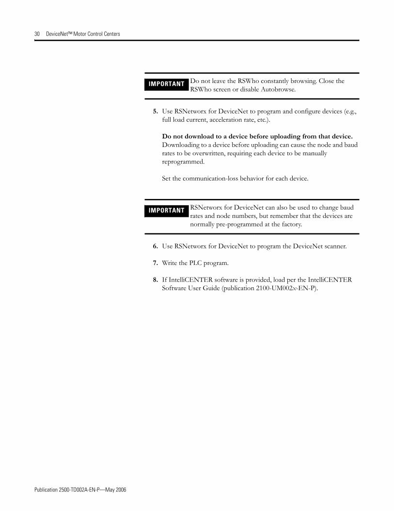
5. Use RSNetworx for DeviceNet to program and configure devices (e.g., full load current, acceleration rate, etc.).
Do not download to a device before uploading from that device. Downloading to a device before uploading can cause the node and baud rates to be overwritten, requiring each device to be manually reprogrammed.
Set the communication-loss behavior for each device.
6. Use RSNetworx for DeviceNet to program the DeviceNet scanner.
7. Write the PLC program.
8. If IntelliCENTER software is provided, load per the IntelliCENTER Software User Guide (publication 2100-UM002x-EN-P).
IMPORTANT Do not leave the RSWho constantly browsing. Close the RSWho screen or disable Autobrowse.
IMPORTANT RSNetworx for DeviceNet can also be used to change baud rates and node numbers, but remember that the devices are normally pre-programmed at the factory.

Publication 2500-TD002A-EN-P—May 2006
DeviceNet™ Motor Control Centers 31
How to Find Electronic Data Sheets (EDS)
Background
After installing IntelliCENTER software, an Electronic Data Sheet (EDS) file must be registered for each unique device in the MCC. This section describes the procedure to perform this task.
Definition of EDS Files
EDS files are simple text files used by network configuration tools—such as RSNetworx, and IntelliCENTER software—to help identify products and easily commission them on a network. EDS files describe a product’s device type, revision and configurable parameters on a DeviceNet network.
Necessary EDS Files
The IntelliCENTER data CD contains a directory (<cdrom>:\<order>\<item>\EDS) of EDS files necessary for the devices in your IntelliCENTER MCC. The EDS files will be automatically registered by the installation program.
For DeviceNet MCCs, a “EDS file” CD is provided. This CD contains EDS files for all DeviceNet products found in MCCs.
Installing EDS Files
EDS files are installed with a program from Rockwell Software called “RSHWare.exe.” This program is included on the IntelliCENTER data CD (in the same directory as the EDS files).
To install EDS files:
1. Run the program RSHWare.exe.
2. Click Add/Remove.
3. Select Register an EDS file. Click Next.
4. Select Register a directory of EDS files.
5. Browse to the EDS directory on the data CD.
6. Click Next.
7. The Installer will display the test results. Click Next to continue.
8. The Installer will allow you to change the graphic image for each device. Click Next to continue.
9. The Installer will display the final task summary. Click Next to continue.
10. Click Finish when completed.

Publication 2500-TD002A-EN-P—May 2006
32 DeviceNet™ Motor Control Centers
Finding EDS Files for Other Devices
EDS files can be obtained at http://www.ab.com/networks/eds.
Uploading EDS Files from the Device
RSNetworx for DeviceNet can be used to upload an EDS file directly from a device. If an EDS file cannot be found by other methods, refer to the RSNetworx help file for steps to upload an EDS file.
Rockwell Automation Support
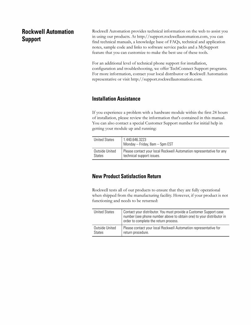
Rockwell Automation provides technical information on the web to assist you in using our products. At http://support.rockwellautomation.com, you can find technical manuals, a knowledge base of FAQs, technical and application notes, sample code and links to software service packs and a MySupport feature that you can customize to make the best use of these tools.
For an additional level of technical phone support for installation, configuration and troubleshooting, we offer TechConnect Support programs. For more information, contact your local distributor or Rockwell Automation representative or visit http://support.rockwellautomation.com.
Installation Assistance
If you experience a problem with a hardware module within the first 24 hours of installation, please review the information that's contained in this manual. You can also contact a special Customer Support number for initial help in getting your module up and running:
New Product Satisfaction Return
Rockwell tests all of our products to ensure that they are fully operational when shipped from the manufacturing facility. However, if your product is not functioning and needs to be returned:
United States 1.440.646.3223Monday – Friday, 8am – 5pm EST
Outside United States
Please contact your local Rockwell Automation representative for any technical support issues.
United States Contact your distributor. You must provide a Customer Support case number (see phone number above to obtain one) to your distributor in order to complete the return process.
Outside United States
Please contact your local Rockwell Automation representative for return procedure.

Publication 2500-TD002A-EN-P – May 2006 Copyright © 2006 Rockwell Automation, Inc. All rights reserved. Printed in the U.S.A.


