96
Engineering Department Last Updated: March 2017 Central Survey Group CAD Standard

Engineering Department
Last Updated: March 2017
Central Survey Group
CAD Standard
da
Engineering Department Manual
Central Survey Group CAD Standard
Last Updated: March 2017 Page ii
TABLE OF CONTENTS
8.0 Central Survey Group CAD Standard 4 8.1 Foreword 4 8.2 Purpose 4
8.2.1 About this Standard 4 8.3 Digital Submittal Requirements 4
8.3.1 CAD File Format 4 8.3.2 Civil 3D Project Format 5 8.3.3 Schedule 5 8.3.4 Media and Format 5 8.3.5 Identification 5 8.3.6 Project Websites 5
8.4 Accessing the CSG CAD Standard 6 8.4.1 Using The Standard Files 7 8.4.2 Distribution Files 7
8.5 Project Directory Structure 8 8.5.1 Project Directory Structure 8 8.5.2 CSG Service Request Number (SRN) 9
8.6 CAD Practices and Procedures 10 8.6.1 Layering Scheme Definition 10 8.6.2 Multi-Level Information 11 8.6.3 Entity and Layer Linetypes 11 8.6.4 Entity and Layer Colors 11 8.6.5 Symbology 11 8.6.6 Plotted Lineweights 12 8.6.7 Text Style and Heights 14 8.6.8 Drawing Units and Precision 15 8.6.9 Coordinate System 15 8.6.10 Coordinate Grids 15 8.6.11 Drawing Accuracy 15
8.7 Plan Set Creation 15 8.7.1 Using the Revision Block within the Contract Border 16
8.8 Data Collection Practices and Procedures 16 8.8.1 Description Keys 16 8.8.2 Sign Locations 16
8.9 File Naming Convention 16 8.9.1 Geometry Drawings 16
8.10 Aerial Mapping Requirements 17 8.10.1 Coordinate System 17 8.10.2 Sector Grid 17 8.10.3 Aerial Photographs 17 8.10.4 File Names 17
8.11 Appendix A – Layer Strategem 18 8.11.1 Alignments 18 8.11.2 Buildings 18 8.11.3 Control 18 8.11.4 Environmental 19 8.11.5 General 19 8.11.6 Hypsography 19 8.11.7 Legal 20 8.11.8 Markings 20 8.11.9 Pavement 21 8.11.10 Profiles 21 8.11.11 Railroad 22 8.11.12 Sections 22 8.11.13 Sign 22 8.11.14 Site Work 23
Engineering Department Manual
Central Survey Group CAD Standard
Last Updated: March 2017 Page iii
8.11.15 Utilities 23 8.11.16 Points 26
8.12 Appendix B - Field Description Code 28 8.13 Appendix C - Linetypes 43 8.14 Appendix D – Symbols by Feature Set 52
8.14.1 Feature Set: Out of Service 52 8.14.2 Feature Set: Building 52 8.14.3 Feature Set: Control 53 8.14.4 Feature Set: Environmental 53 8.14.5 Feature Set: General 54 8.14.6 Feature Set: Hypsography 55 8.14.7 Feature Set: Pavement Markings 55 8.14.8 Feature Set: Pavement, Road, and Parking 56 8.14.9 Feature Set: Railroad 57 8.14.10 Feature Set: Sign 58 8.14.11 Feature Set: Site Features 59 8.14.12 Feature Set: Utilities 63
8.15 Appendix E – Legends- Linetypes 87 8.16 Appendix F – Contract Borders 88
8.16.1 Contract Border 88 8.16.2 Contract Border - OS 89 8.16.3 Contract Border - AM 90
8.17 Appendix G - Civil 3D 91 8.17.1 Data Shortcuts (Civil 3D Object Sharing) 91 8.17.2 Sharing Data Shortcuts 91 8.17.3 Pipe Networks 93
8.18 Appendix H - Request To Change Standard 95 8.19 Appendix I - Changes to the Standards 96
Engineering Department Manual
Central Survey Group CAD Standard
Last Updated: March 2017 Page 4
8.0 CENTRAL SURVEY GROUP CAD STANDARD
8.1 FOREWORD
The Central Survey Group Computer Aided Drafting Standard outlined within this document was established to provide guidance for the preparation and maintenance of facility CAD drawings.
This document is intended for use by both in-house personnel as well as outside consultants involved in creating or updating PANYNJ facilities’ Computer Aided Drafting (CAD) data.
8.2 PURPOSE
This Standard establishes requirements and procedures for the preparation and submission of CAD based drawings throughout the project life cycle. Adherence to this standard ensures that the Central Survey Group of the PANYNJ will receive and produce data in a consistent format. This consistency will improve the compatibility of this data with the E/A Design Division and will allow the PANYNJ to maximize its investment in mapping by capturing and effectively using extended information.
The role of an individual assigned to the project determines the level of understanding required of the CSG CAD Standard. For CAD operators, surveyors, and functional supervisors a thorough knowledge of all CAD related elements associated with a project is crucial. The project manager however only requires a general knowledge of the CSG CAD Standard and the means by which it is employed to create a project. Both levels of knowledge will be possible using this manual.
The CAD system adopted by the PANYNJ is comprised of several Autodesk products. Throughout this manual, terminology and references will be made that are unique to Autodesk and primarily different AutoCAD based software applications.
8.2.1 ABOUT THIS STANDARD
The chapters within this standard describe how the Central Survey Group uses AutoCAD and how to configure AutoCAD to support the CSG CAD Standard, which it has adopted.
8.3 DIGITAL SUBMITTAL REQUIREMENTS
This Standard adopts AutoCAD Civil 3D as the “Standard CAD Software”. Even so, AutoCAD is in no way endorsed over any other product and there is no requirement that consultants use AutoCAD software to draft their design. Consultants may prepare their drawings using the CAD software of their choice but deliverables must be AutoCAD (.dwg) files that conform to the standards and procedures set forth by this document. Additionally, softcopy (CAD files) must include all information presented on the hardcopy (plots). This precludes the use of stick-back, graphic tapes, hand lettering and anything else which is placed on the drawing after it is plotted excepting any signatures and seals.
8.3.1 CAD FILE FORMAT
All digital CAD files shall be compatible with the release of AutoCAD currently used by the PANYNJ. When submitting files on electric media, the version of AutoCAD is to be noted. All project data used to create any drawing content is to accompany all CAD files submitted. If AutoCAD is not used to create the drawing content, all alignment, terrain model, profile, geometry point and pipe network data is to be supplied in LANDXML format. Geometry point data can also be supplied in the ascii (PNEZD) comma delimited file format.

Engineering Department Manual
Central Survey Group CAD Standard
Last Updated: March 2017 Page 5
8.3.2 CIVIL 3D PROJECT FORMAT
When using AutoCAD Civil 3D, data shortcuts are to be used for sharing C3D data between files. A data shortcuts folder is to do be set up within the Project Data folder and is to be named “C3D_Datashortcuts”. This folder is to be included with all deliverables.
For a more in-depth breakdown on how to use C3D within the PANYNJ reference the Civil 3D Section which is included within Section 8.17 titled Appendix G - Civil 3D.
8.3.3 SCHEDULE
Consultants are required to submit digital CAD files (softcopy) concurrent with each hardcopy submittal. Refer to individual contracts for specific submittal schedules. DWG and DWF / PDF files are required for each milestone submittal. If the project does not have a milestone submission, then DWG and DWF / PDF files are required no later than 1 week prior to the Final submittal.
8.3.4 MEDIA AND FORMAT
AutoCAD drawing files will be submitted on media CDs. All disks are to be delivered virus free. Final hardcopies of each sheet must use the PANYNJ Contract Border identified in this standard and must be submitted at full size, either 22x34 or 34x56. Submitted hardcopies must use archival paper with Permalife® plotter paper specifications. Engineering Department staff will verify that submissions contain the “Permalife 25% cotton content” watermark.
Please refer to 8.16 Appendix F – Contract Borders.
8.3.5 IDENTIFICATION
Prior to submission all digital submittal media CDs must be labeled with the following information:
Consultant’s name and Survey Request Number (SRN)
Contact name and phone number of consulting project manager
Discipline-Facility (e.g. Central Survey-JFK)
Submittal Date and Percent Complete
Data Format (e.g. AutoCAD Version .dwg)
File Name(s) on CD
As much information as possible should be printed on both the CD label and the CD case. If all the information will not fit on either the CD label or the CD case, the information can be listed in any orderly manner in a text file that will be copied to the CD in electronic format.
8.3.6 PROJECT WEBSITES
The PANYNJ is in the process of developing a “Project Extranet” to enhance collaboration between in-house surveyors and outside consultants, as well as with different departments and divisions throughout the agency. All Project Websites have a folder structure similar to that described in 8.4 Accessing the CSG CAD Standard in this standard.
Please refer to the project specifics to determine if a Project Website is available for use. If so, all transfer of digital information will be made via the website. Transfer of data via e-mail or CDs is not permitted if a project website is available.
If a Project Website is available for the project the Project Website link will be provided along with a Username and a Password.
Engineering Department Manual
Central Survey Group CAD Standard
Last Updated: March 2017 Page 6
8.4 ACCESSING THE CSG CAD STANDARD
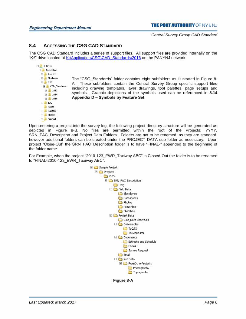
The CSG CAD Standard includes a series of support files. All support files are provided internally on the “K:\” drive located at K:\Application\CSG\CAD_Standards\2016 on the PANYNJ network.
The “CSG_Standards” folder contains eight subfolders as illustrated in Figure 8-A. These subfolders contain the Central Survey Group specific support files including drawing templates, layer drawings, tool palettes, page setups and symbols. Graphic depictions of the symbols used can be referenced in 8.14 Appendix D – Symbols by Feature Set.
Upon entering a project into the survey log, the following project directory structure will be generated as depicted in Figure 8-B. No files are permitted within the root of the Projects, YYYY, SRN_FAC_Description and Project Data Folders. Folders are not to be renamed, as they are standard, however additional folders can be created under the PROJECT DATA sub folder as necessary. Upon project “Close-Out” the SRN_FAC_Description folder is to have “FINAL-“ appended to the beginning of the folder name.
For Example, when the project “2010-123_EWR_Taxiway ABC” is Closed-Out the folder is to be renamed to “FINAL-2010-123_EWR_Taxiway ABC”.
Figure 8-A
Engineering Department Manual
Central Survey Group CAD Standard
Last Updated: March 2017 Page 7
8.4.1 USING THE STANDARD FILES
The CSG_Standards directory contains two primary types of files: files that do not require ongoing user interaction and those that do.
The first type refers to support files accessed automatically by AutoCAD once they have been copied to the proper support folders. All CSG workstations have already been configured to access these files. Outside consultants should copy these files to the appropriate directories or create an AutoCAD profile pointing to the files as necessary.
The second type refers to files such as title sheets, contract borders and stamps, which the user must configure within the project. For instructions on creating a title sheet or working with the contract borders, refer to 8.7 Plan Set Creation in this standard.
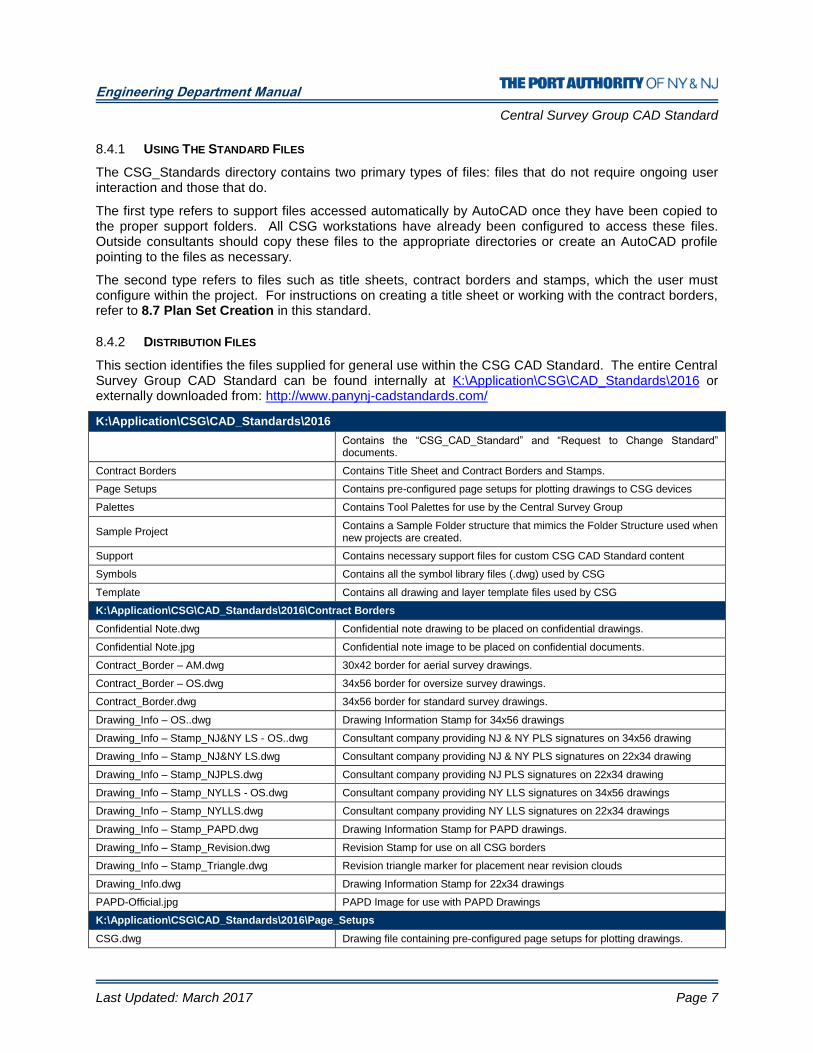
8.4.2 DISTRIBUTION FILES
This section identifies the files supplied for general use within the CSG CAD Standard. The entire Central Survey Group CAD Standard can be found internally at K:\Application\CSG\CAD_Standards\2016 or externally downloaded from: http://www.panynj-cadstandards.com/
K:\Application\CSG\CAD_Standards\2016
Contains the “CSG_CAD_Standard” and “Request to Change Standard” documents.
Contract Borders Contains Title Sheet and Contract Borders and Stamps.
Page Setups Contains pre-configured page setups for plotting drawings to CSG devices
Palettes Contains Tool Palettes for use by the Central Survey Group
Sample Project Contains a Sample Folder structure that mimics the Folder Structure used when new projects are created.
Support Contains necessary support files for custom CSG CAD Standard content
Symbols Contains all the symbol library files (.dwg) used by CSG
Template Contains all drawing and layer template files used by CSG
K:\Application\CSG\CAD_Standards\2016\Contract Borders
Confidential Note.dwg Confidential note drawing to be placed on confidential drawings.
Confidential Note.jpg Confidential note image to be placed on confidential documents.
Contract_Border – AM.dwg 30x42 border for aerial survey drawings.
Contract_Border – OS.dwg 34x56 border for oversize survey drawings.
Contract_Border.dwg 34x56 border for standard survey drawings.
Drawing_Info – OS..dwg Drawing Information Stamp for 34x56 drawings
Drawing_Info – Stamp_NJ&NY LS - OS..dwg Consultant company providing NJ & NY PLS signatures on 34x56 drawing
Drawing_Info – Stamp_NJ&NY LS.dwg Consultant company providing NJ & NY PLS signatures on 22x34 drawing
Drawing_Info – Stamp_NJPLS.dwg Consultant company providing NJ PLS signatures on 22x34 drawing
Drawing_Info – Stamp_NYLLS - OS.dwg Consultant company providing NY LLS signatures on 34x56 drawings
Drawing_Info – Stamp_NYLLS.dwg Consultant company providing NY LLS signatures on 22x34 drawings
Drawing_Info – Stamp_PAPD.dwg Drawing Information Stamp for PAPD drawings.
Drawing_Info – Stamp_Revision.dwg Revision Stamp for use on all CSG borders
Drawing_Info – Stamp_Triangle.dwg Revision triangle marker for placement near revision clouds
Drawing_Info.dwg Drawing Information Stamp for 22x34 drawings
PAPD-Official.jpg PAPD Image for use with PAPD Drawings
K:\Application\CSG\CAD_Standards\2016\Page_Setups
CSG.dwg Drawing file containing pre-configured page setups for plotting drawings.
Engineering Department Manual
Central Survey Group CAD Standard
Last Updated: March 2017 Page 8
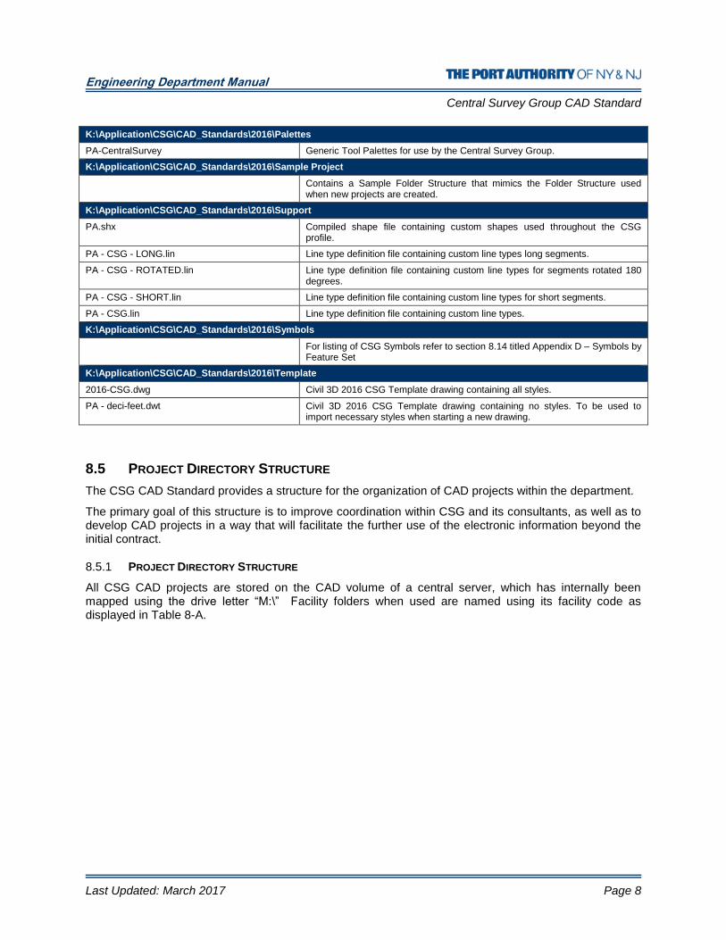
K:\Application\CSG\CAD_Standards\2016\Palettes
PA-CentralSurvey Generic Tool Palettes for use by the Central Survey Group.
K:\Application\CSG\CAD_Standards\2016\Sample Project
Contains a Sample Folder Structure that mimics the Folder Structure used when new projects are created.
K:\Application\CSG\CAD_Standards\2016\Support
PA.shx Compiled shape file containing custom shapes used throughout the CSG profile.
PA - CSG - LONG.lin Line type definition file containing custom line types long segments.
PA - CSG - ROTATED.lin Line type definition file containing custom line types for segments rotated 180 degrees.
PA - CSG - SHORT.lin Line type definition file containing custom line types for short segments.
PA - CSG.lin Line type definition file containing custom line types.
K:\Application\CSG\CAD_Standards\2016\Symbols
For listing of CSG Symbols refer to section 8.14 titled Appendix D – Symbols by Feature Set
K:\Application\CSG\CAD_Standards\2016\Template
2016-CSG.dwg Civil 3D 2016 CSG Template drawing containing all styles.
PA - deci-feet.dwt Civil 3D 2016 CSG Template drawing containing no styles. To be used to import necessary styles when starting a new drawing.
8.5 PROJECT DIRECTORY STRUCTURE
The CSG CAD Standard provides a structure for the organization of CAD projects within the department.
The primary goal of this structure is to improve coordination within CSG and its consultants, as well as to develop CAD projects in a way that will facilitate the further use of the electronic information beyond the initial contract.
8.5.1 PROJECT DIRECTORY STRUCTURE
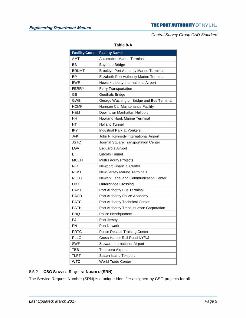
All CSG CAD projects are stored on the CAD volume of a central server, which has internally been mapped using the drive letter “M:\” Facility folders when used are named using its facility code as displayed in Table 8-A.
Engineering Department Manual
Central Survey Group CAD Standard
Last Updated: March 2017 Page 9
Table 8-A
Facility Code Facility Name
AMT Automobile Marine Terminal
BB Bayonne Bridge
BRKMT Brooklyn Port Authority Marine Terminal
EP Elizabeth Port Authority Marine Terminal
EWR Newark Liberty International Airport
FERRY Ferry Transportation
GB Goethals Bridge
GWB George Washington Bridge and Bus Terminal
HCMF Harrison Car Maintenance Facility
HELI Downtown Manhattan Heliport
HH Howland Hook Marine Terminal
HT Holland Tunnel
IPY Industrial Park at Yonkers
JFK John F. Kennedy International Airport
JSTC Journal Square Transportation Center
LGA Laguardia Airport
LT Lincoln Tunnel
MULTI Multi Facility Projects
NFC Newport Financial Center
NJMT New Jersey Marine Terminals
NLCC Newark Legal and Communication Center
OBX Outerbridge Crossing
PABT Port Authority Bus Terminal
PACD Port Authority Police Academy
PATC Port Authority Technical Center
PATH Port Authority Trans-Hudson Corporation
PHQ Police Headquarters
PJ Port Jersey
PN Port Newark
PRTC Police Rescue Training Center
RLLC Cross Harbor Rail Road NY/NJ
SWF Stewart International Airport
TEB Teterboro Airport
TLPT Staten Island Teleport
WTC World Trade Center
8.5.2 CSG SERVICE REQUEST NUMBER (SRN)
The Service Request Number (SRN) is a unique identifier assigned by CSG projects for all.
Engineering Department Manual
Central Survey Group CAD Standard
Last Updated: March 2017 Page 10
8.6 CAD PRACTICES AND PROCEDURES
CAD drawing files must be consistently formatted in order to provide an effective method of data dissemination and retrieval. To that end, this Standard will guide the user in the requirements of CADD file naming, layer naming, graphic symbology, lettering styles, drawing units and other features.
8.6.1 LAYERING SCHEME DEFINITION
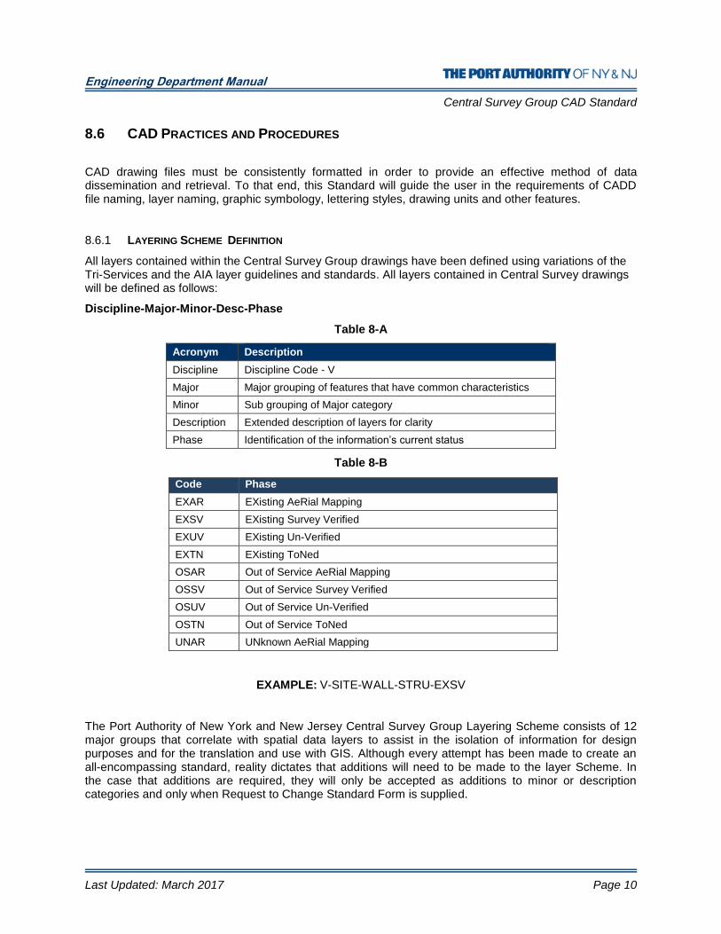
All layers contained within the Central Survey Group drawings have been defined using variations of the Tri-Services and the AIA layer guidelines and standards. All layers contained in Central Survey drawings will be defined as follows:
Discipline-Major-Minor-Desc-Phase
Table 8-A
Acronym Description
Discipline Discipline Code - V
Major Major grouping of features that have common characteristics
Minor Sub grouping of Major category
Description Extended description of layers for clarity
Phase Identification of the information’s current status
Table 8-B
EXAMPLE: V-SITE-WALL-STRU-EXSV
The Port Authority of New York and New Jersey Central Survey Group Layering Scheme consists of 12 major groups that correlate with spatial data layers to assist in the isolation of information for design purposes and for the translation and use with GIS. Although every attempt has been made to create an all-encompassing standard, reality dictates that additions will need to be made to the layer Scheme. In the case that additions are required, they will only be accepted as additions to minor or description categories and only when Request to Change Standard Form is supplied.
Code Phase
EXAR EXisting AeRial Mapping
EXSV EXisting Survey Verified
EXUV EXisting Un-Verified
EXTN EXisting ToNed
OSAR Out of Service AeRial Mapping
OSSV Out of Service Survey Verified
OSUV Out of Service Un-Verified
OSTN Out of Service ToNed
UNAR UNknown AeRial Mapping

Engineering Department Manual
Central Survey Group CAD Standard
Last Updated: March 2017 Page 11
8.6.2 MULTI-LEVEL INFORMATION
The layer Scheme has been defined to support the use of a numeral at the end of the descriptor field to identify multi-level information. This is to accommodate those areas where ramps, bridges and overpasses must be identified. For example, an airport terminal with a departure ramp that is over the arrival area. In this case, the layer naming convention for all information relating to departures shall be suffixed with the numeral “1” to denote the first level of information over ground level. An example of the layer names is as follows:
EXAMPLE: V-PAVE-ROAD-ASPH1-EXSV
The numeral “1” following the descriptor “ASPH1” denotes that this is the first level of pavement above ground level.
8.6.3 ENTITY AND LAYER LINETYPES
All entities must have their linetype assigned “bylayer” not “byentity” with the exception that entities within symbols may have linetype assigned “byblock”. For a complete list of linetypes provided refer 8.13 Appendix C - Linetypes
8.6.4 ENTITY AND LAYER COLORS
All entities will be drawn on the specified layers and must have color assigned “bylayer” not “byentity” with the exception that entities within “blocks” may have color assigned “byblock”. Layer color assignments are included in the layer definitions provided.
8.6.5 SYMBOLOGY
Symbols that consultants are to use in their AutoCAD drawings are available in this Standard. Each of the available symbols is illustrated in this publication. This symbology is based on current practices as well as symbology defined by the American National Standards Institute (ANSI) and other governing agencies.
The graphic representation of symbology in this Standard shows the relative proportion of the symbol. For a complete list of Symbols provided refer to 8.14 Appendix D – Symbols by Feature Set
8.6.5.1 SCALABLE SYMBOLS
Scalable symbols are created with the intent that they will appear the same size when plotted at different scales.
Symbols are created on Layer “0” and will automatically take on the characteristics of the layer they are inserted on. All symbols will be inserted on the layer identified within this standard.
For ease of use, the insertion scale factor of each scalable symbol will depend on the plot scale.

Engineering Department Manual
Central Survey Group CAD Standard
Last Updated: March 2017 Page 12
For Example: If the scale of the viewport is 1:30, then each symbol inserted in the drawing will be scaled up by a factor of 30.
8.6.5.2 NON-SCALABLE SYMBOLS
Non-Scalable symbols are created with the intent that they will appear at true size for all plot scales.
Symbols are created on Layer “0” and will automatically take on the characteristics of the layer they are inserted on. All symbols will be inserted on the layer identified within this standard.
The insertion scale factor for all Non-Scalable symbols will be “1”.
8.6.5.3 CREATING SYMBOLS
Symbols must be documented and supplied to the CAD committee in digital format as a single AutoCAD drawing file accompanied by a plot of the symbol and a Request to Chang Standard Form found in section 8.18.
Symbols will be created on Layer “0”. Other layers may be present in the drawing for supplemental information such as text within the symbol.
Symbols will be created using the current version of AutoCAD software in use by the E/A Design Division.
Colors and Linetypes will always be set to “bylayer”.
Text within the symbol will utilize one of the Text Styles provided within this standard so that it is legible upon plotting.
The symbol will be drawn so that the insertion point is located appropriately and is at 0,0,0.
The “base” of the drawing will be set to 0,0,0.
The symbol drawing will be purged of all unused blocks, layers, linetypes, text styles, etc.
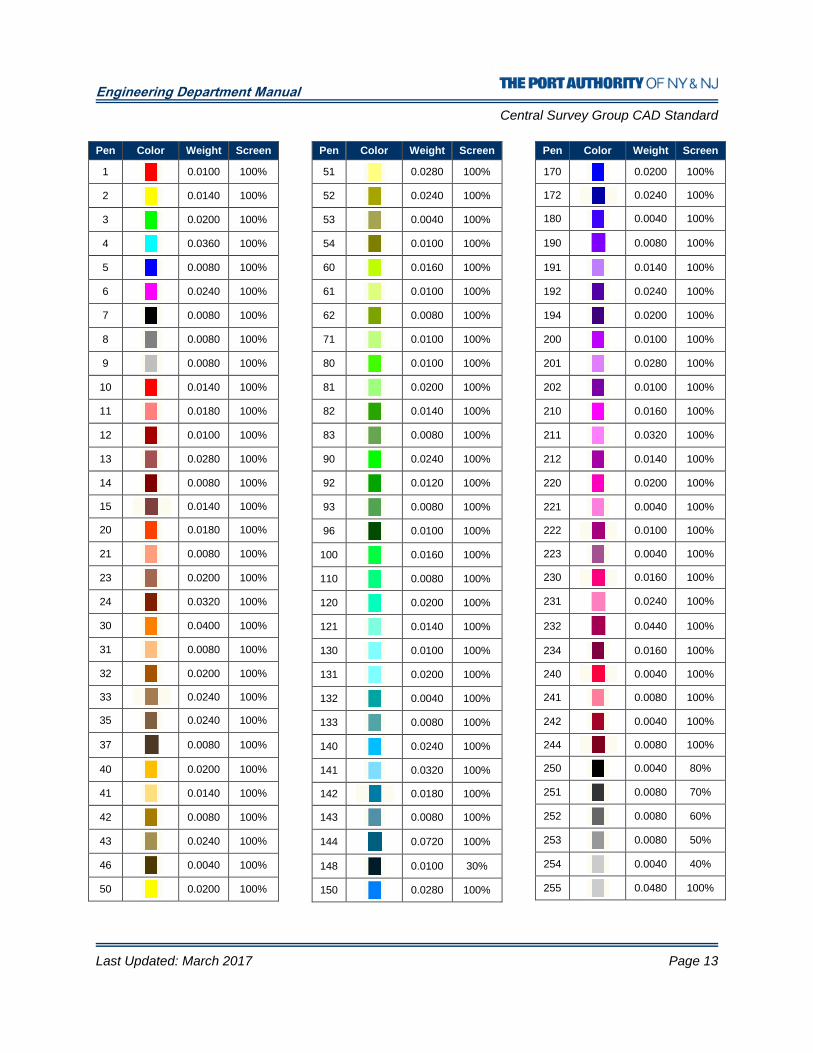
8.6.6 PLOTTED LINEWEIGHTS
The colors used in the layer definitions provided within this standard correspond to plotted pen weights. AutoCAD products make use of a CTB file to assign pen weights to object colors. All E/A Design Division Contract Drawings are to be plotted using the “PA-Master.ctb” file that is provided with this standard. Many variables within the CTB file remain constant throughout the pen assignments, these variables are defined in Table 8-C. The pen numbers, lineweights and percent screening assigned to the pens used in the “PA-MasterFull.ctb” file are displayed in Table 8-H.
Table 8-C
Variable Value
Color Black
Dither On
Virtual Pen Number Automatic
Linetype Use Object Linetype
Adaptive On
Line End Style Use Object End Style
Line Join Style Miter
Fill Style Use Object Fill Style
Engineering Department Manual
Central Survey Group CAD Standard
Last Updated: March 2017 Page 13
Pen Color Weight Screen
1
0.0100 100%
2
0.0140 100%
3
0.0200 100%
4
0.0360 100%
5
0.0080 100%
6
0.0240 100%
7
0.0080 100%
8
0.0080 100%
9
0.0080 100%
10
0.0140 100%
11
0.0180 100%
12
0.0100 100%
13
0.0280 100%
14
0.0080 100%
15 0.0140 100%
20
0.0180 100%
21
0.0080 100%
23
0.0200 100%
24
0.0320 100%
30
0.0400 100%
31
0.0080 100%
32
0.0200 100%
33 0.0240 100%
35
0.0240 100%
37
0.0080 100%
40
0.0200 100%
41
0.0140 100%
42
0.0080 100%
43
0.0240 100%
46
0.0040 100%
50
0.0200 100%
Pen Color Weight Screen
51
0.0280 100%
52
0.0240 100%
53
0.0040 100%
54
0.0100 100%
60
0.0160 100%
61
0.0100 100%
62
0.0080 100%
71
0.0100 100%
80
0.0100 100%
81
0.0200 100%
82
0.0140 100%
83
0.0080 100%
90
0.0240 100%
92
0.0120 100%
93
0.0080 100%
96
0.0100 100%
100
0.0160 100%
110
0.0080 100%
120
0.0200 100%
121
0.0140 100%
130
0.0100 100%
131
0.0200 100%
132
0.0040 100%
133
0.0080 100%
140
0.0240 100%
141
0.0320 100%
142 0.0180 100%
143
0.0080 100%
144
0.0720 100%
148
0.0100 30%
150
0.0280 100%
Pen Color Weight Screen
170
0.0200 100%
172 0.0240 100%
180
0.0040 100%
190
0.0080 100%
191
0.0140 100%
192
0.0240 100%
194
0.0200 100%
200
0.0100 100%
201
0.0280 100%
202
0.0100 100%
210
0.0160 100%
211
0.0320 100%
212
0.0140 100%
220
0.0200 100%
221
0.0040 100%
222 0.0100 100%
223
0.0040 100%
230 0.0160 100%
231
0.0240 100%
232
0.0440 100%
234
0.0160 100%
240 0.0040 100%
241
0.0080 100%
242
0.0040 100%
244 0.0080 100%
250
0.0040 80%
251
0.0080 70%
252
0.0080 60%
253
0.0080 50%
254
0.0040 40%
255
0.0480 100%

Engineering Department Manual
Central Survey Group CAD Standard
Last Updated: March 2017 Page 14
8.6.7 TEXT STYLE AND HEIGHTS
To promote consistency in Contract Drawings as well as prevent the use of “third-party” un-licensed AutoCAD font files, and to ensure a consistent plotted appearance of text, only ARIALN.TTF and ARIAL.TTF fonts are permitted for use on Central Survey Group Drawings.
Eight Text Styles have been provided as part of this standard. Three of the Text Styles provided (ARIAL, ARIALN, and Linefont) are used for Contract Border, Drawing Information or Linetype definitions and are not permitted for general use by the disciplines. The remaining five Text Styles provided, which are permitted for use by the disciplines are created as annotative styles. Annotative styles allow the AutoCAD product to scale the text heights appropriately based on the scale of the plotted drawing. The Text Styles provided are:
Text Style Plotted Height
Annotative Font Description of Usage Usable by
Disciplines
PA – 0.06 0.06” Yes Arial Point and Utility Text Yes
PA – 0.10 0.10” Yes Arial Normal Text Yes
PA – 0.15 0.15” Yes Arial Headings Yes
PA – 0.20 0.20” Yes Arial Titles Yes
PA – 0.25 0.25” Yes Arial Alternate Titles Yes
Linefont 0.10” No RomanS Linetype Definitions No
ARIALN Varies No Arial Narrow Contract Border and Drawing Info No
ARIAL Varies No Arial Contract Border and Drawing Info No
Recommended text heights are defined below:
Use Plotted Height
Major Titles 0.20”
Subtitles 0.15”
Notes, dimensions, etc. 0.10”
Point & Utility Labels 0.06”
Multi-Leader Style Arrow Head Content
PA-Arrow Closed Filled Arrow 0.10” Mtext
PA-Loop Open Loop 0.10” Mtext
PA-Circle Dot Blank 0.10” Mtext
PA-Dot Dot 0.10” Mtext
PA-Integral Integral 0.10” Mtext
PA-DOT-Keynote-Box Dot Box
PA-DOT-Keynote-Circle Dot Circle
PA-DOT-Keynote-Hex Dot Hexagon
Engineering Department Manual
Central Survey Group CAD Standard
Last Updated: March 2017 Page 15
8.6.8 DRAWING UNITS AND PRECISION
All drawings shall be provided in decimal units with one drawing unit equal to one foot. Civil 3D drawings, Field book files and Land XML files are to have the Survey Units set to US Survey Foot.
8.6.9 COORDINATE SYSTEM
All drawings must be positioned on the local x-y grid with north defined straight up the page.
Files that are “attached” using AutoCAD’s XREF command should always use the coordinate 0,0 for two-dimensional files or 0,0,0 for three-dimensional files as the insertion point and a zero rotation angle.
Drawings submitted to the Central Survey Group should not have the User Coordinate Systems (UCS) defined. They should not be twisted with the “Dview” command and should be on a fixed coordinate system as defined by the Central Survey Group.
8.6.10 COORDINATE GRIDS
All drawing files shall be submitted with a coordinate grid drawn and labeled with northings and eastings. The basis for this grid will be determined by the Central Survey Group at the time of project award.
8.6.11 DRAWING ACCURACY
All entities that illustrate elements of construction must be input using dimensional data. Scanning, and/or digitizing are not an acceptable method of entry unless approved in advance by the Central Survey Group. Digitizing is allowed for site-oriented, non-construction features such as topography.
8.7 PLAN SET CREATION
All digital submittals are to adhere to the following standards. All drawing files submitted should be named based on the file naming conventions provided under the topic File Naming Conventions later in this document.
Drawings provided are to follow the following format. For mapping that will be provided on a single sheet, a border shall be inserted into the mapping drawing’s Layout1 environment. A view-port shall be created in Layout1 and the plan is to be “zoomed” to the appropriate scale. The Layout1 environment is to be plotted at a scale of 1 drawing unit = 1 paper inch and the Layout is to be renamed to match the sheet number of the sheet.
For mapping that will be submitted on from 2 to 6 sheets, up to 6 Layout tabs are to be created. Borders shall be inserted into each Layout tab in the mapping drawing. A view-port shall be created for each border and each view-port shall be “zoomed” to the appropriate area and scale. Each Layout tab shall be renamed to match the sheet number of the sheet being plotted from that tab.
For mapping that will be submitted on more than 6 sheets, a series of plot drawings shall be created. Each drawing shall contain a maximum of 6 Layout tabs. The mapping drawing shall be externally referenced to each plot drawing. A view-port shall be created for each border and each view-port shall be “zoomed” to the appropriate area and scale. Each Layout tab shall be renamed to match the sheet number of the sheet being plotted from that tab.
The drawing file shall be saved with the first Layout displayed.

Engineering Department Manual
Central Survey Group CAD Standard
Last Updated: March 2017 Page 16
8.7.1 USING THE REVISION BLOCK WITHIN THE CONTRACT BORDER
A revision block named “Drawing_Info – Stamp_Revision.dwg” has been provided with the CSG CAD Standard. When revisions are made, this block is to be inserted using an endpoint snap to the upper left corner of the previous revision line. Figure 8-D displays where the revision stamp is to be inserted. The stamp is located on the network at:
K:\Application\CSG\CAD_Standards\2016\Contract Borders
Once inserted the revision block will prompt the user for information pertaining to the revision. Under no circumstances will the revision block be exploded or modified.
8.8 DATA COLLECTION PRACTICES AND PROCEDURES
8.8.1 DESCRIPTION KEYS
Field data collection codes formatted for Civil 3D are provided in this standard. The Data Collection codes are configured to support the symbols and Layers defined in this standard. For a complete list of Description Keys refer to 8.12 Appendix B - Field Description Code.
8.8.2 SIGN LOCATIONS
All signs located in the field shall correspond to a sign number on the sign inventory sheet located at the end of this document. The sign shall be attributed with the corresponding number from these sign inventory drawings. If a sign is located that is not represented on the sign inventory drawings, a digital photograph shall be taken of the sign and provided in JPG format. The image shall consist of facility abbreviation suffixed with the sector number of the sign location and a unique sequential number of the signs located during the project. For example, the first sign located on sector 10 of a job at Kennedy Airport will be named JFK-10-1.JPG. This same name shall be assigned as the survey located point description in the CAD drawing file. The JPG images of all signs shall be provided on CD with the drawings.
The location of all runway and taxiway signs must be rotated to the appropriate orientation. When locating Runway and Taxiway signs, all concrete and asphalt bases are to be located.
8.9 FILE NAMING CONVENTION
When submitting electronic documents to the Port Authority CSG each drawing shall be named in accordance with the following standard.
8.9.1 GEOMETRY DRAWINGS
A Geometry drawing is the actual mapping drawing and may contain from one to six plot sheets defined in paperspace / layout space.
[CSG HOLD NUM]_[ FACILITY CODE ]_[ FIELD WORK START DATE ]_[ COORDINATE SYSTEM CODE ] _[DESCRIPTION]
Figure 8-D
Engineering Department Manual
Central Survey Group CAD Standard
Last Updated: March 2017 Page 17
Geometry drawings shall be named starting with the CSG Hold Number, followed by the Facility Code, followed by the Coordinate System Code, followed by the Field Work Start Date in the format YYYYMMDD drawing for mapping at Port Newark on January 15, 2004 with a CSG Survey Request Number of 2004-125 would be named:
2004-125_PN_20040115_NJ83F_GroundFeatures.dwg
8.10 AERIAL MAPPING REQUIREMENTS
These requirements support the Port Authority’s continuing effort to organize, consolidate, and standardize the information generated and consumed by the all divisions within the agency. The objective of these requirements is to make the data files easier for users to identify and integrate in planning and design.
8.10.1 COORDINATE SYSTEM
All submissions should include a data set that is in the Port Authority standard coordinate system for that particular facility (State Plane, NAD 1983).
8.10.2 SECTOR GRID
The Central Survey Group prior to the mapping capture will supply a defined sector grid. Included in the deliverable should be the mapping as a whole and divided by the sector grid supplied.
8.10.3 AERIAL PHOTOGRAPHS
Georeferenced aerial photograph data sets should include georeferencing files ("world files") for each image file.
8.10.4 FILE NAMES
Files that are delivered in the form of a data set broken up into sectors should be named according to the following guidelines: The name of each file should include:
a) The CSG hold number b) The facility code c) The date the data was captured as an 8 digit code YYYYMMDD (January 28, 2003 would be represented as 20030128) d) The abbreviation for the coordinate system that the data is in using the AutoCAD MAP abbreviations. e) The sector name
Example: 2004-125_EWR_20030128-NJ83_106-126.dwg
Engineering Department Manual
Central Survey Group CAD Standard
Last Updated: March 2017 Page 18
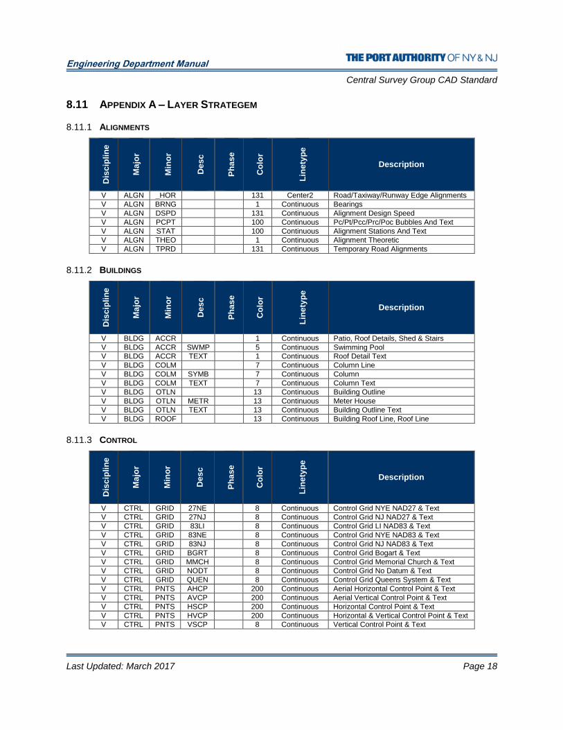
8.11 APPENDIX A – LAYER STRATEGEM
8.11.1 ALIGNMENTS
Dis
cip
lin
e
Ma
jor
Min
or
De
sc
Ph
as
e
Co
lor
Lin
ety
pe
Description
V ALGN _HOR 131 Center2 Road/Taxiway/Runway Edge Alignments
V ALGN BRNG 1 Continuous Bearings
V ALGN DSPD 131 Continuous Alignment Design Speed
V ALGN PCPT 100 Continuous Pc/Pt/Pcc/Prc/Poc Bubbles And Text
V ALGN STAT 100 Continuous Alignment Stations And Text
V ALGN THEO 1 Continuous Alignment Theoretic
V ALGN TPRD 131 Continuous Temporary Road Alignments
8.11.2 BUILDINGS
Dis
cip
lin
e
Ma
jor
Min
or
Des
c
Ph
as
e
Co
lor
Lin
ety
pe
Description
V BLDG ACCR 1 Continuous Patio, Roof Details, Shed & Stairs
V BLDG ACCR SWMP 5 Continuous Swimming Pool
V BLDG ACCR TEXT 1 Continuous Roof Detail Text
V BLDG COLM 7 Continuous Column Line
V BLDG COLM SYMB 7 Continuous Column
V BLDG COLM TEXT 7 Continuous Column Text
V BLDG OTLN 13 Continuous Building Outline
V BLDG OTLN METR 13 Continuous Meter House
V BLDG OTLN TEXT 13 Continuous Building Outline Text
V BLDG ROOF 13 Continuous Building Roof Line, Roof Line
8.11.3 CONTROL
Dis
cip
lin
e
Ma
jor
Min
or
Des
c
Ph
as
e
Co
lor
Lin
ety
pe
Description
V CTRL GRID 27NE 8 Continuous Control Grid NYE NAD27 & Text
V CTRL GRID 27NJ 8 Continuous Control Grid NJ NAD27 & Text
V CTRL GRID 83LI 8 Continuous Control Grid LI NAD83 & Text
V CTRL GRID 83NE 8 Continuous Control Grid NYE NAD83 & Text
V CTRL GRID 83NJ 8 Continuous Control Grid NJ NAD83 & Text
V CTRL GRID BGRT 8 Continuous Control Grid Bogart & Text
V CTRL GRID MMCH 8 Continuous Control Grid Memorial Church & Text
V CTRL GRID NODT 8 Continuous Control Grid No Datum & Text
V CTRL GRID QUEN 8 Continuous Control Grid Queens System & Text
V CTRL PNTS AHCP 200 Continuous Aerial Horizontal Control Point & Text
V CTRL PNTS AVCP 200 Continuous Aerial Vertical Control Point & Text
V CTRL PNTS HSCP 200 Continuous Horizontal Control Point & Text
V CTRL PNTS HVCP 200 Continuous Horizontal & Vertical Control Point & Text
V CTRL PNTS VSCP 8 Continuous Vertical Control Point & Text
Engineering Department Manual
Central Survey Group CAD Standard
Last Updated: March 2017 Page 19
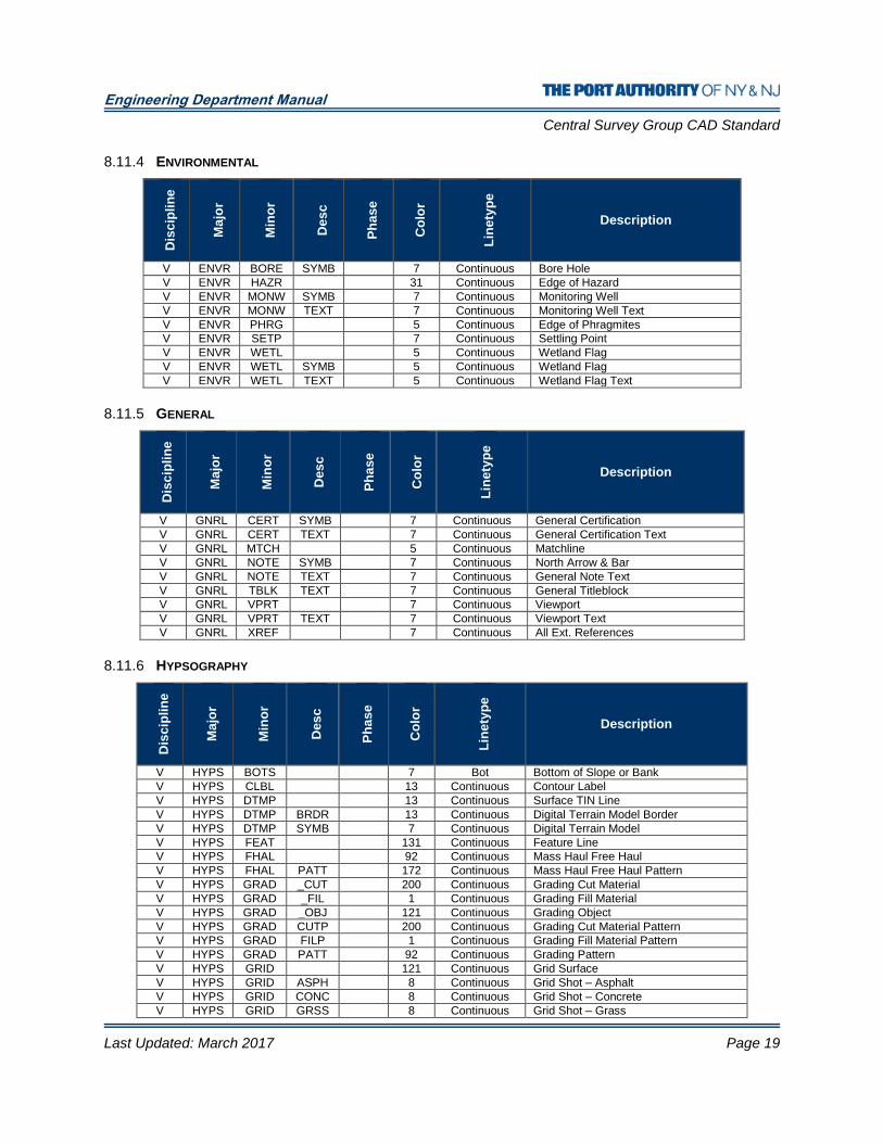
8.11.4 ENVIRONMENTAL D
isc
ipli
ne
Ma
jor
Min
or
De
sc
Ph
as
e
Co
lor
Lin
ety
pe
Description
V ENVR BORE SYMB 7 Continuous Bore Hole
V ENVR HAZR 31 Continuous Edge of Hazard
V ENVR MONW SYMB 7 Continuous Monitoring Well
V ENVR MONW TEXT 7 Continuous Monitoring Well Text
V ENVR PHRG 5 Continuous Edge of Phragmites
V ENVR SETP 7 Continuous Settling Point
V ENVR WETL 5 Continuous Wetland Flag
V ENVR WETL SYMB 5 Continuous Wetland Flag
V ENVR WETL TEXT 5 Continuous Wetland Flag Text
8.11.5 GENERAL
Dis
cip
lin
e
Ma
jor
Min
or
Des
c
Ph
as
e
Co
lor
Lin
ety
pe
Description
V GNRL CERT SYMB 7 Continuous General Certification
V GNRL CERT TEXT 7 Continuous General Certification Text
V GNRL MTCH 5 Continuous Matchline
V GNRL NOTE SYMB 7 Continuous North Arrow & Bar
V GNRL NOTE TEXT 7 Continuous General Note Text
V GNRL TBLK TEXT 7 Continuous General Titleblock
V GNRL VPRT 7 Continuous Viewport
V GNRL VPRT TEXT 7 Continuous Viewport Text
V GNRL XREF 7 Continuous All Ext. References
8.11.6 HYPSOGRAPHY
Dis
cip
lin
e
Ma
jor
Min
or
Des
c
Ph
as
e
Co
lor
Lin
ety
pe
Description
V HYPS BOTS 7 Bot Bottom of Slope or Bank
V HYPS CLBL 13 Continuous Contour Label
V HYPS DTMP 13 Continuous Surface TIN Line
V HYPS DTMP BRDR 13 Continuous Digital Terrain Model Border
V HYPS DTMP SYMB 7 Continuous Digital Terrain Model
V HYPS FEAT 131 Continuous Feature Line
V HYPS FHAL 92 Continuous Mass Haul Free Haul
V HYPS FHAL PATT 172 Continuous Mass Haul Free Haul Pattern
V HYPS GRAD _CUT 200 Continuous Grading Cut Material
V HYPS GRAD _FIL 1 Continuous Grading Fill Material
V HYPS GRAD _OBJ 121 Continuous Grading Object
V HYPS GRAD CUTP 200 Continuous Grading Cut Material Pattern
V HYPS GRAD FILP 1 Continuous Grading Fill Material Pattern
V HYPS GRAD PATT 92 Continuous Grading Pattern
V HYPS GRID 121 Continuous Grid Surface
V HYPS GRID ASPH 8 Continuous Grid Shot – Asphalt
V HYPS GRID CONC 8 Continuous Grid Shot – Concrete
V HYPS GRID GRSS 8 Continuous Grid Shot – Grass
Engineering Department Manual
Central Survey Group CAD Standard
Last Updated: March 2017 Page 20
V HYPS GRID GRVL 8 Continuous Grid Shot – Gravel
V HYPS MAJR 13 Continuous Major Contour
V HYPS MAJR TEXT 13 Continuous Major Contour Text
V HYPS MHAL 12 Continuous Mass Haul
V HYPS MHAL GRID 8 Continuous Mass Haul Grid Line
V HYPS MHAL TEXT 12 Continuous Mass Haul Text
V HYPS MINR 252 Continuous Minor Contour
V HYPS MINR TEXT 252 Continuous Minor Contour Text
V HYPS MJRD 13 Continuous Depression Major Contour
V HYPS MJRD TEXT 13 Continuous Depression Major Contour Text
V HYPS MNRD 252 Continuous Depression Minor Contour
V HYPS MNRD TEXT 252 Continuous Depression Minor Contour Text
V HYPS OHAL PATT 100 Continuous Mass Haul Over Haul Pattern
V HYPS SCTN 12 Continuous Grading Section
V HYPS SLOP 12 Continuous Surface Slope
V HYPS SPOT SYMB 7 Continuous Spot Shot
V HYPS TEXT 12 Continuous Miscellaneous Text
V HYPS TOPS 7 Top Top of Slope or Bank
V HYPS USER 12 Continuous Surface User Defined Contour
V HYPS WSHD 13 Continuous Surface Watershed
V HYPS WSHD TEXT 13 Continuous Surface Watershed Text
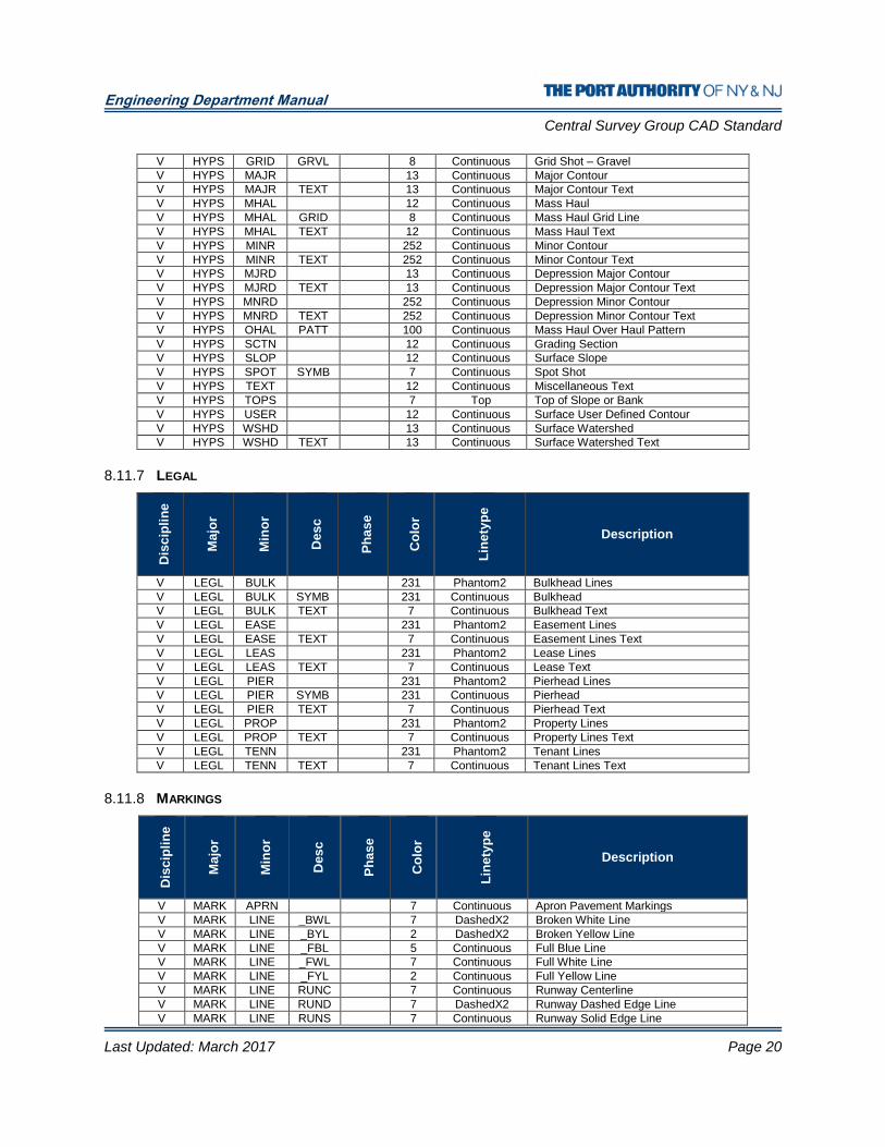
8.11.7 LEGAL
Dis
cip
lin
e
Ma
jor
Min
or
Des
c
Ph
as
e
Co
lor
Lin
ety
pe
Description
V LEGL BULK 231 Phantom2 Bulkhead Lines
V LEGL BULK SYMB 231 Continuous Bulkhead
V LEGL BULK TEXT 7 Continuous Bulkhead Text
V LEGL EASE 231 Phantom2 Easement Lines
V LEGL EASE TEXT 7 Continuous Easement Lines Text
V LEGL LEAS 231 Phantom2 Lease Lines
V LEGL LEAS TEXT 7 Continuous Lease Text
V LEGL PIER 231 Phantom2 Pierhead Lines
V LEGL PIER SYMB 231 Continuous Pierhead
V LEGL PIER TEXT 7 Continuous Pierhead Text
V LEGL PROP 231 Phantom2 Property Lines
V LEGL PROP TEXT 7 Continuous Property Lines Text
V LEGL TENN 231 Phantom2 Tenant Lines
V LEGL TENN TEXT 7 Continuous Tenant Lines Text
8.11.8 MARKINGS
Dis
cip
lin
e
Ma
jor
Min
or
Des
c
Ph
as
e
Co
lor
Lin
ety
pe
Description
V MARK APRN 7 Continuous Apron Pavement Markings
V MARK LINE _BWL 7 DashedX2 Broken White Line
V MARK LINE _BYL 2 DashedX2 Broken Yellow Line
V MARK LINE _FBL 5 Continuous Full Blue Line
V MARK LINE _FWL 7 Continuous Full White Line
V MARK LINE _FYL 2 Continuous Full Yellow Line
V MARK LINE RUNC 7 Continuous Runway Centerline
V MARK LINE RUND 7 DashedX2 Runway Dashed Edge Line
V MARK LINE RUNS 7 Continuous Runway Solid Edge Line

Engineering Department Manual
Central Survey Group CAD Standard
Last Updated: March 2017 Page 21
V MARK LINE STOP 7 Continuous Solid Stop Line
V MARK LINE TAXC 7 Continuous Taxiway Centerline
V MARK LINE TAXD 7 DashedX2 Taxiway Dashed Edge Line
V MARK LINE TAXS 7 Continuous Taxiway Solid Edge Line
V MARK SYMB ARWS 7 Continuous Directional Arrow Symbols
V MARK SYMB HAND 5 Continuous Handicapped Symbol
V MARK SYMB RUNW 7 Continuous Miscellaneous Runway Markings
V MARK SYMB TEXT 5 Continuous Painted Text (“ONLY”, “STOP”)
8.11.9 PAVEMENT
Dis
cip
lin
e
Ma
jor
Min
or
De
sc
Ph
as
e
Co
lor
Lin
ety
pe
Description
V PAVE APRN ASPH 200 Continuous Edge of Apron – Asphalt
V PAVE APRN CONC 7 Continuous Edge of Apron - Concrete
V PAVE ASPH 200 Continuous Edge of Pavement – Asphalt
V PAVE BRDG _STL 252 Continuous Bridge – Steel
V PAVE BRDG CONC 7 Continuous Bridge – Concrete
V PAVE CBAR 7 Continuous Jersey or Concrete Barrier
V PAVE CBMP SYMB 7 Continuous Concrete Bumper
V PAVE CONC 7 Continuous Edge of Pavement – Concrete
V PAVE CRBB 200 Continuous Bottom of Curb
V PAVE CRBT 7 Continuous Top of Curb
V PAVE CRCK 7 Continuous Pavement Cracks
V PAVE DCUB 7 Hidden Drop Curb
V PAVE DLIN SYMB 7 Continuous Delineator
V PAVE DUCT SYMB 7 Continuous Super Duct – Traffic Guide
V PAVE GRVL 200 Continuous Edge of Pavement – Gravel
V PAVE GUTR 7 Continuous Gutter
V PAVE HAND SYMB 5 Continuous Handicapped Ramp
V PAVE IMPA 13 Continuous Impact Attenuator
V PAVE JONT 80 Continuous Joints
V PAVE NAME 7 Continuous Road Name Annotation
V PAVE REFL SYMB 7 Continuous Reflector
V PAVE SBMP 251 Continuous Speed Bump
V PAVE TRAL 200 Dashed Centerline of Trail
V PAVE UNPV 200 Continuous Edge of Pavement – Unpaved
V PAVE WALK 7 Continuous Sidewalk
8.11.10 PROFILES
Dis
cip
lin
e
Ma
jor
Min
or
Des
c
Ph
as
e
Co
lor
Lin
ety
pe
Description
V PROF 131 Continuous Profile Features
V PROF _EGL 172 Continuous Energy Grade Line
V PROF _HGL 100 Dashed High Grade Line
V PROF GRID 250 Continuous Profile View Grid Line
V PROF GRID _CUT 1 Continuous Profile View Cut
V PROF GRID _FIL 130 Continuous Profile View Fill
V PROF OFST 92 Dashed Offset Profile
V PROF TEXT 100 Continuous Misc. Text & Callouts With Assoc. Leader Lines
V PROF THEO 1 Continuous Theoretic Profile Feature
Engineering Department Manual
Central Survey Group CAD Standard
Last Updated: March 2017 Page 22
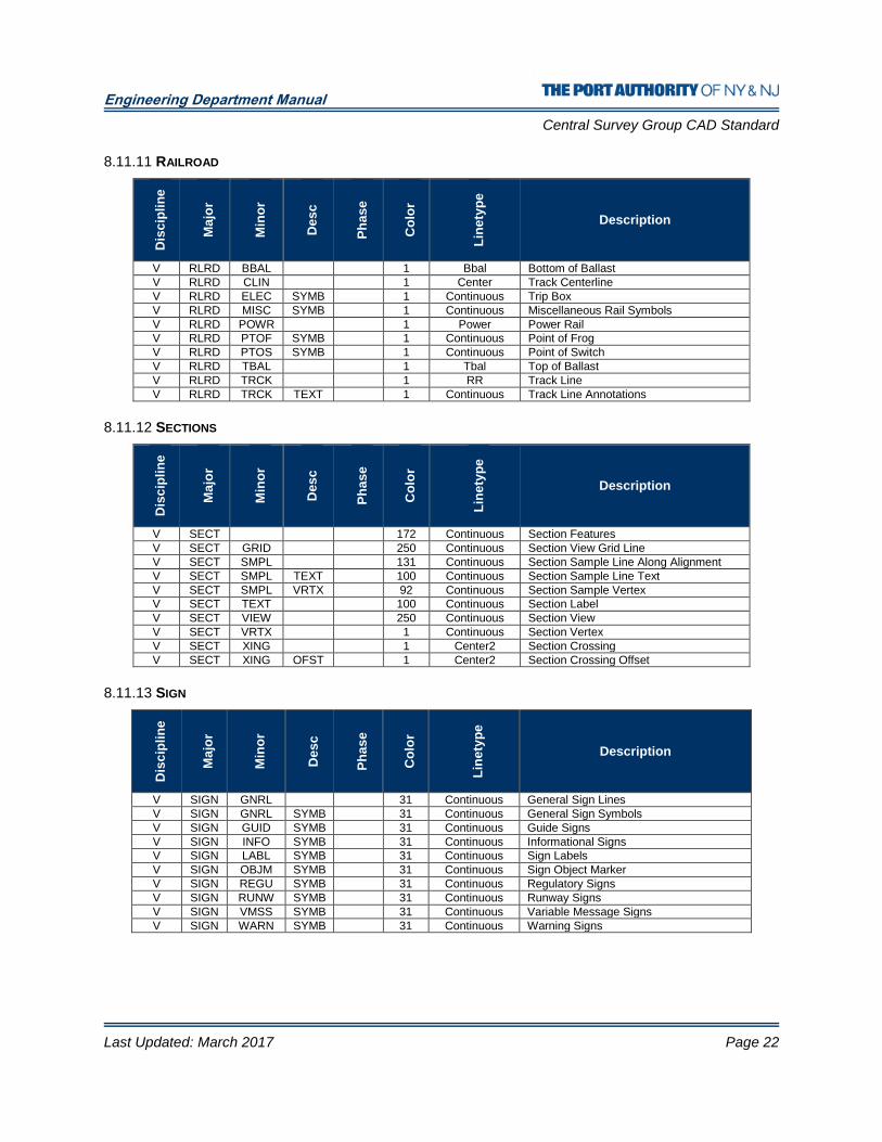
8.11.11 RAILROAD D
isc
ipli
ne
Ma
jor
Min
or
De
sc
Ph
as
e
Co
lor
Lin
ety
pe
Description
V RLRD BBAL 1 Bbal Bottom of Ballast
V RLRD CLIN 1 Center Track Centerline
V RLRD ELEC SYMB 1 Continuous Trip Box
V RLRD MISC SYMB 1 Continuous Miscellaneous Rail Symbols
V RLRD POWR 1 Power Power Rail
V RLRD PTOF SYMB 1 Continuous Point of Frog
V RLRD PTOS SYMB 1 Continuous Point of Switch
V RLRD TBAL 1 Tbal Top of Ballast
V RLRD TRCK 1 RR Track Line
V RLRD TRCK TEXT 1 Continuous Track Line Annotations
8.11.12 SECTIONS
Dis
cip
lin
e
Ma
jor
Min
or
Des
c
Ph
as
e
Co
lor
Lin
ety
pe
Description
V SECT 172 Continuous Section Features
V SECT GRID 250 Continuous Section View Grid Line
V SECT SMPL 131 Continuous Section Sample Line Along Alignment
V SECT SMPL TEXT 100 Continuous Section Sample Line Text
V SECT SMPL VRTX 92 Continuous Section Sample Vertex
V SECT TEXT 100 Continuous Section Label
V SECT VIEW 250 Continuous Section View
V SECT VRTX 1 Continuous Section Vertex
V SECT XING 1 Center2 Section Crossing
V SECT XING OFST 1 Center2 Section Crossing Offset
8.11.13 SIGN
Dis
cip
lin
e
Ma
jor
Min
or
Des
c
Ph
as
e
Co
lor
Lin
ety
pe
Description
V SIGN GNRL 31 Continuous General Sign Lines
V SIGN GNRL SYMB 31 Continuous General Sign Symbols
V SIGN GUID SYMB 31 Continuous Guide Signs
V SIGN INFO SYMB 31 Continuous Informational Signs
V SIGN LABL SYMB 31 Continuous Sign Labels
V SIGN OBJM SYMB 31 Continuous Sign Object Marker
V SIGN REGU SYMB 31 Continuous Regulatory Signs
V SIGN RUNW SYMB 31 Continuous Runway Signs
V SIGN VMSS SYMB 31 Continuous Variable Message Signs
V SIGN WARN SYMB 31 Continuous Warning Signs
Engineering Department Manual
Central Survey Group CAD Standard
Last Updated: March 2017 Page 23
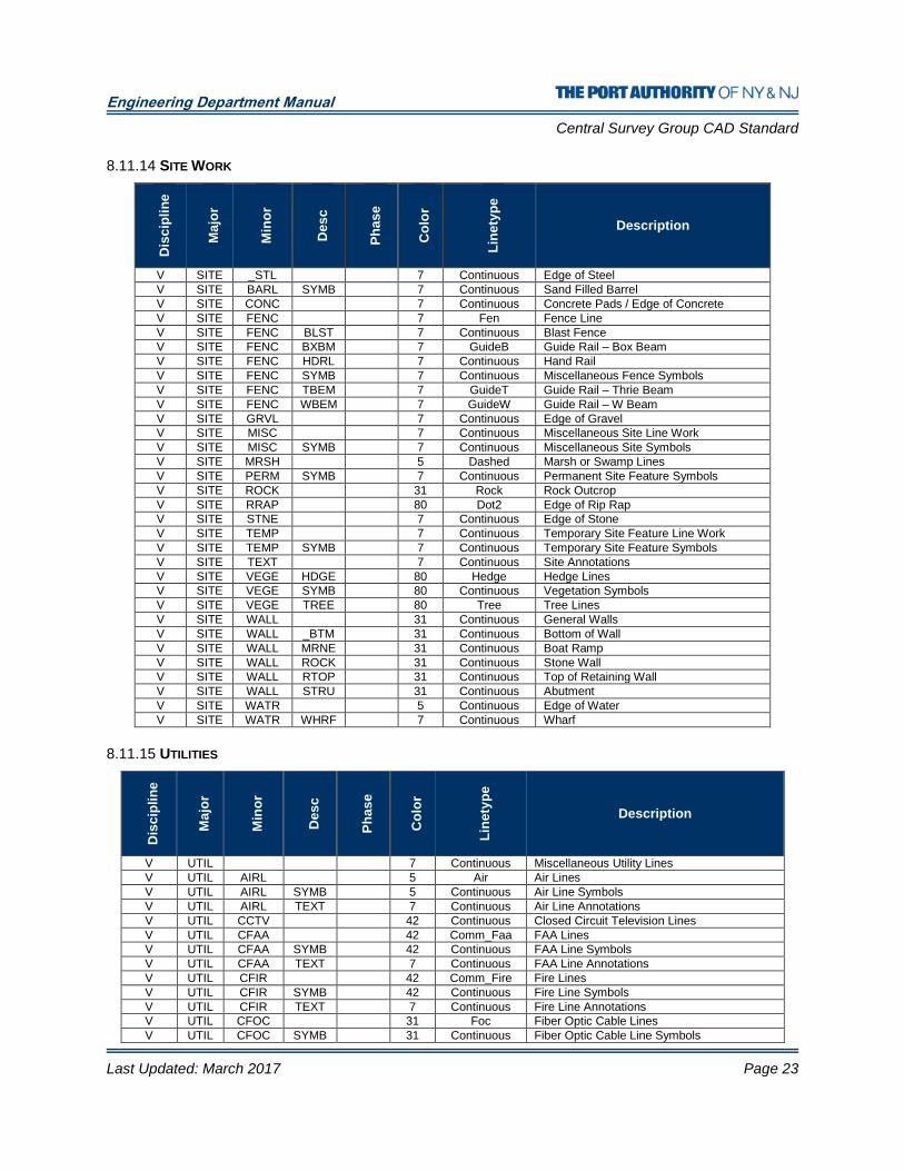
8.11.14 SITE WORK D
isc
ipli
ne
Ma
jor
Min
or
De
sc
Ph
as
e
Co
lor
Lin
ety
pe
Description
V SITE _STL 7 Continuous Edge of Steel
V SITE BARL SYMB 7 Continuous Sand Filled Barrel
V SITE CONC 7 Continuous Concrete Pads / Edge of Concrete
V SITE FENC 7 Fen Fence Line
V SITE FENC BLST 7 Continuous Blast Fence
V SITE FENC BXBM 7 GuideB Guide Rail – Box Beam
V SITE FENC HDRL 7 Continuous Hand Rail
V SITE FENC SYMB 7 Continuous Miscellaneous Fence Symbols
V SITE FENC TBEM 7 GuideT Guide Rail – Thrie Beam
V SITE FENC WBEM 7 GuideW Guide Rail – W Beam
V SITE GRVL 7 Continuous Edge of Gravel
V SITE MISC 7 Continuous Miscellaneous Site Line Work
V SITE MISC SYMB 7 Continuous Miscellaneous Site Symbols
V SITE MRSH 5 Dashed Marsh or Swamp Lines
V SITE PERM SYMB 7 Continuous Permanent Site Feature Symbols
V SITE ROCK 31 Rock Rock Outcrop
V SITE RRAP 80 Dot2 Edge of Rip Rap
V SITE STNE 7 Continuous Edge of Stone
V SITE TEMP 7 Continuous Temporary Site Feature Line Work
V SITE TEMP SYMB 7 Continuous Temporary Site Feature Symbols
V SITE TEXT 7 Continuous Site Annotations
V SITE VEGE HDGE 80 Hedge Hedge Lines
V SITE VEGE SYMB 80 Continuous Vegetation Symbols
V SITE VEGE TREE 80 Tree Tree Lines
V SITE WALL 31 Continuous General Walls
V SITE WALL _BTM 31 Continuous Bottom of Wall
V SITE WALL MRNE 31 Continuous Boat Ramp
V SITE WALL ROCK 31 Continuous Stone Wall
V SITE WALL RTOP 31 Continuous Top of Retaining Wall
V SITE WALL STRU 31 Continuous Abutment
V SITE WATR 5 Continuous Edge of Water
V SITE WATR WHRF 7 Continuous Wharf
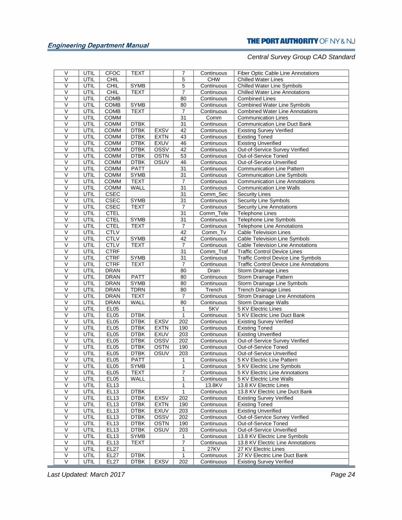
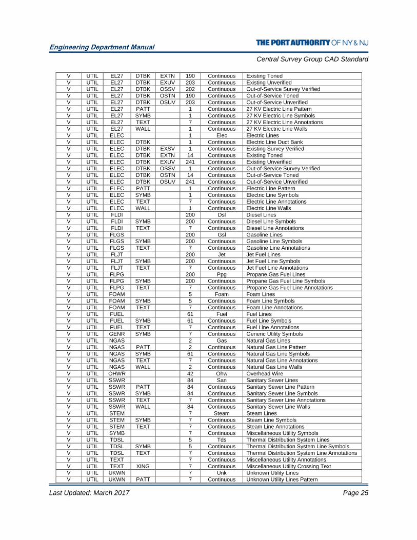
8.11.15 UTILITIES
Dis
cip
lin
e
Ma
jor
Min
or
Des
c
Ph
as
e
Co
lor
Lin
ety
pe
Description
V UTIL 7 Continuous Miscellaneous Utility Lines
V UTIL AIRL 5 Air Air Lines
V UTIL AIRL SYMB 5 Continuous Air Line Symbols
V UTIL AIRL TEXT 7 Continuous Air Line Annotations
V UTIL CCTV 42 Continuous Closed Circuit Television Lines
V UTIL CFAA 42 Comm_Faa FAA Lines
V UTIL CFAA SYMB 42 Continuous FAA Line Symbols
V UTIL CFAA TEXT 7 Continuous FAA Line Annotations
V UTIL CFIR 42 Comm_Fire Fire Lines
V UTIL CFIR SYMB 42 Continuous Fire Line Symbols
V UTIL CFIR TEXT 7 Continuous Fire Line Annotations
V UTIL CFOC 31 Foc Fiber Optic Cable Lines
V UTIL CFOC SYMB 31 Continuous Fiber Optic Cable Line Symbols
Engineering Department Manual
Central Survey Group CAD Standard
Last Updated: March 2017 Page 24
V UTIL CFOC TEXT 7 Continuous Fiber Optic Cable Line Annotations
V UTIL CHIL 5 CHW Chilled Water Lines
V UTIL CHIL SYMB 5 Continuous Chilled Water Line Symbols
V UTIL CHIL TEXT 7 Continuous Chilled Water Line Annotations
V UTIL COMB 80 Continuous Combined Lines
V UTIL COMB SYMB 80 Continuous Combined Water Line Symbols
V UTIL COMB TEXT 7 Continuous Combined Water Line Annotations
V UTIL COMM 31 Comm Communication Lines
V UTIL COMM DTBK 31 Continuous Communication Line Duct Bank
V UTIL COMM DTBK EXSV 42 Continuous Existing Survey Verified
V UTIL COMM DTBK EXTN 43 Continuous Existing Toned
V UTIL COMM DTBK EXUV 46 Continuous Existing Unverified
V UTIL COMM DTBK OSSV 42 Continuous Out-of-Service Survey Verified
V UTIL COMM DTBK OSTN 53 Continuous Out-of-Service Toned
V UTIL COMM DTBK OSUV 46 Continuous Out-of-Service Unverified
V UTIL COMM PATT 31 Continuous Communication Line Pattern
V UTIL COMM SYMB 31 Continuous Communication Line Symbols
V UTIL COMM TEXT 7 Continuous Communication Line Annotations
V UTIL COMM WALL 31 Continuous Communication Line Walls
V UTIL CSEC 31 Comm_Sec Security Lines
V UTIL CSEC SYMB 31 Continuous Security Line Symbols
V UTIL CSEC TEXT 7 Continuous Security Line Annotations
V UTIL CTEL 31 Comm_Tele Telephone Lines
V UTIL CTEL SYMB 31 Continuous Telephone Line Symbols
V UTIL CTEL TEXT 7 Continuous Telephone Line Annotations
V UTIL CTLV 42 Comm_Tv Cable Television Lines
V UTIL CTLV SYMB 42 Continuous Cable Television Line Symbols
V UTIL CTLV TEXT 7 Continuous Cable Television Line Annotations
V UTIL CTRF 31 Comm_Traf Traffic Control Device Lines
V UTIL CTRF SYMB 31 Continuous Traffic Control Device Line Symbols
V UTIL CTRF TEXT 7 Continuous Traffic Control Device Line Annotations
V UTIL DRAN 80 Drain Storm Drainage Lines
V UTIL DRAN PATT 80 Continuous Storm Drainage Pattern
V UTIL DRAN SYMB 80 Continuous Storm Drainage Line Symbols
V UTIL DRAN TDRN 80 Trench Trench Drainage Lines
V UTIL DRAN TEXT 7 Continuous Strom Drainage Line Annotations
V UTIL DRAN WALL 80 Continuous Storm Drainage Walls
V UTIL EL05 1 5KV 5 KV Electric Lines
V UTIL EL05 DTBK 1 Continuous 5 KV Electric Line Duct Bank
V UTIL EL05 DTBK EXSV 202 Continuous Existing Survey Verified
V UTIL EL05 DTBK EXTN 190 Continuous Existing Toned
V UTIL EL05 DTBK EXUV 203 Continuous Existing Unverified
V UTIL EL05 DTBK OSSV 202 Continuous Out-of-Service Survey Verified
V UTIL EL05 DTBK OSTN 190 Continuous Out-of-Service Toned
V UTIL EL05 DTBK OSUV 203 Continuous Out-of-Service Unverified
V UTIL EL05 PATT 1 Continuous 5 KV Electric Line Pattern
V UTIL EL05 SYMB 1 Continuous 5 KV Electric Line Symbols
V UTIL EL05 TEXT 7 Continuous 5 KV Electric Line Annotations
V UTIL EL05 WALL 1 Continuous 5 KV Electric Line Walls
V UTIL EL13 1 13.8KV 13.8 KV Electric Lines
V UTIL EL13 DTBK 1 Continuous 13.8 KV Electric Line Duct Bank
V UTIL EL13 DTBK EXSV 202 Continuous Existing Survey Verified
V UTIL EL13 DTBK EXTN 190 Continuous Existing Toned
V UTIL EL13 DTBK EXUV 203 Continuous Existing Unverified
V UTIL EL13 DTBK OSSV 202 Continuous Out-of-Service Survey Verified
V UTIL EL13 DTBK OSTN 190 Continuous Out-of-Service Toned
V UTIL EL13 DTBK OSUV 203 Continuous Out-of-Service Unverified
V UTIL EL13 SYMB 1 Continuous 13.8 KV Electric Line Symbols
V UTIL EL13 TEXT 7 Continuous 13.8 KV Electric Line Annotations
V UTIL EL27 1 27KV 27 KV Electric Lines
V UTIL EL27 DTBK 1 Continuous 27 KV Electric Line Duct Bank
V UTIL EL27 DTBK EXSV 202 Continuous Existing Survey Verified
Engineering Department Manual
Central Survey Group CAD Standard
Last Updated: March 2017 Page 25
V UTIL EL27 DTBK EXTN 190 Continuous Existing Toned
V UTIL EL27 DTBK EXUV 203 Continuous Existing Unverified
V UTIL EL27 DTBK OSSV 202 Continuous Out-of-Service Survey Verified
V UTIL EL27 DTBK OSTN 190 Continuous Out-of-Service Toned
V UTIL EL27 DTBK OSUV 203 Continuous Out-of-Service Unverified
V UTIL EL27 PATT 1 Continuous 27 KV Electric Line Pattern
V UTIL EL27 SYMB 1 Continuous 27 KV Electric Line Symbols
V UTIL EL27 TEXT 7 Continuous 27 KV Electric Line Annotations
V UTIL EL27 WALL 1 Continuous 27 KV Electric Line Walls
V UTIL ELEC 1 Elec Electric Lines
V UTIL ELEC DTBK 1 Continuous Electric Line Duct Bank
V UTIL ELEC DTBK EXSV 1 Continuous Existing Survey Verified
V UTIL ELEC DTBK EXTN 14 Continuous Existing Toned
V UTIL ELEC DTBK EXUV 241 Continuous Existing Unverified
V UTIL ELEC DTBK OSSV 1 Continuous Out-of-Service Survey Verified
V UTIL ELEC DTBK OSTN 14 Continuous Out-of-Service Toned
V UTIL ELEC DTBK OSUV 241 Continuous Out-of-Service Unverified
V UTIL ELEC PATT 1 Continuous Electric Line Pattern
V UTIL ELEC SYMB 1 Continuous Electric Line Symbols
V UTIL ELEC TEXT 7 Continuous Electric Line Annotations
V UTIL ELEC WALL 1 Continuous Electric Line Walls
V UTIL FLDI 200 Dsl Diesel Lines
V UTIL FLDI SYMB 200 Continuous Diesel Line Symbols
V UTIL FLDI TEXT 7 Continuous Diesel Line Annotations
V UTIL FLGS 200 Gsl Gasoline Lines
V UTIL FLGS SYMB 200 Continuous Gasoline Line Symbols
V UTIL FLGS TEXT 7 Continuous Gasoline Line Annotations
V UTIL FLJT 200 Jet Jet Fuel Lines
V UTIL FLJT SYMB 200 Continuous Jet Fuel Line Symbols
V UTIL FLJT TEXT 7 Continuous Jet Fuel Line Annotations
V UTIL FLPG 200 Ppg Propane Gas Fuel Lines
V UTIL FLPG SYMB 200 Continuous Propane Gas Fuel Line Symbols
V UTIL FLPG TEXT 7 Continuous Propane Gas Fuel Line Annotations
V UTIL FOAM 5 Foam Foam Lines
V UTIL FOAM SYMB 5 Continuous Foam Line Symbols
V UTIL FOAM TEXT 7 Continuous Foam Line Annotations
V UTIL FUEL 61 Fuel Fuel Lines
V UTIL FUEL SYMB 61 Continuous Fuel Line Symbols
V UTIL FUEL TEXT 7 Continuous Fuel Line Annotations
V UTIL GENR SYMB 7 Continuous Generic Utility Symbols
V UTIL NGAS 2 Gas Natural Gas Lines
V UTIL NGAS PATT 2 Continuous Natural Gas Line Pattern
V UTIL NGAS SYMB 61 Continuous Natural Gas Line Symbols
V UTIL NGAS TEXT 7 Continuous Natural Gas Line Annotations
V UTIL NGAS WALL 2 Continuous Natural Gas Line Walls
V UTIL OHWR 42 Ohw Overhead Wire
V UTIL SSWR 84 San Sanitary Sewer Lines
V UTIL SSWR PATT 84 Continuous Sanitary Sewer Line Pattern
V UTIL SSWR SYMB 84 Continuous Sanitary Sewer Line Symbols
V UTIL SSWR TEXT 7 Continuous Sanitary Sewer Line Annotations
V UTIL SSWR WALL 84 Continuous Sanitary Sewer Line Walls
V UTIL STEM 7 Steam Steam Lines
V UTIL STEM SYMB 7 Continuous Steam Line Symbols
V UTIL STEM TEXT 7 Continuous Steam Line Annotations
V UTIL SYMB 7 Continuous Miscellaneous Utility Symbols
V UTIL TDSL 5 Tds Thermal Distribution System Lines
V UTIL TDSL SYMB 5 Continuous Thermal Distribution System Line Symbols
V UTIL TDSL TEXT 7 Continuous Thermal Distribution System Line Annotations
V UTIL TEXT 7 Continuous Miscellaneous Utility Annotations
V UTIL TEXT XING 7 Continuous Miscellaneous Utility Crossing Text
V UTIL UKWN 7 Unk Unknown Utility Lines
V UTIL UKWN PATT 7 Continuous Unknown Utility Lines Pattern
Engineering Department Manual
Central Survey Group CAD Standard
Last Updated: March 2017 Page 26
V UTIL UKWN SYMB 7 Continuous Unknown Utility Line Symbols
V UTIL UKWN TEXT 7 Continuous Unknown Utility Line Annotations
V UTIL UKWN WALL 7 Continuous Unknown Utility Line Walls
V UTIL WAHP 5 Water High Pressure Water Lines
V UTIL WAHP SYMB 5 Continuous High Pressure Water Line Symbols V UTIL WAHP TEXT 7 Continuous High Pressure Water Line Annotations V UTIL WAIR 5 Water Irrigation Pressure Water Lines V UTIL WAIR SYMB 5 Continuous Irrigation Pressure Water Line Symbols V UTIL WAIR TEXT 7 Continuous Irrigation Pressure Water Line Annotations V UTIL WALP 5 Water Low Pressure Water Lines V UTIL WALP SYMB 5 Continuous Low Pressure Water Line Symbols V UTIL WALP TEXT 7 Continuous Low Pressure Water Line Annotations V UTIL WAMP 5 Water Medium Pressure Water Lines V UTIL WAMP SYMB 5 Continuous Medium Pressure Water Line Symbols V UTIL WAMP TEXT 7 Continuous Medium Pressure Water Line Annotations V UTIL WATR 5 Water Domestic Water Lines
V UTIL WATR PATT 5 Continuous Domestic Water Line Pattern
V UTIL WATR SYMB 5 Continuous Domestic Water Line Symbols
V UTIL WATR TEXT 7 Continuous Domestic Water Line Annotations
V UTIL WATR WALL 5 Continuous Domestic Water Line Walls
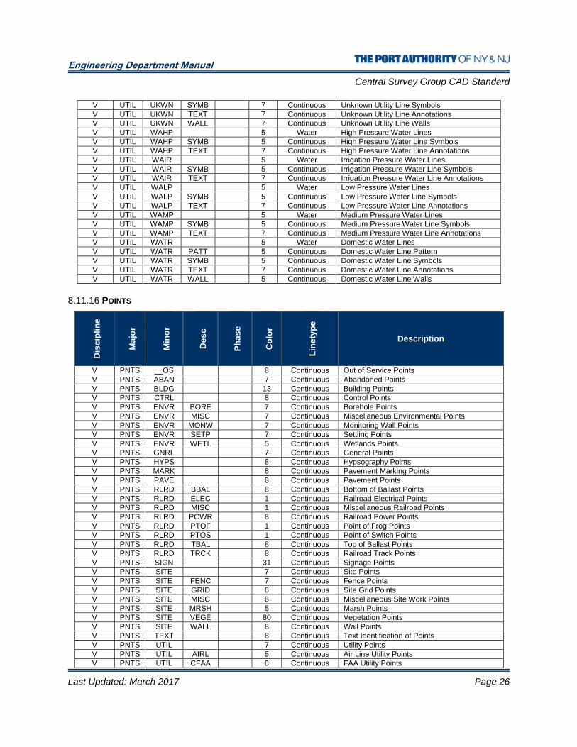
8.11.16 POINTS
Dis
cip
lin
e
Ma
jor
Min
or
Des
c
Ph
as
e
Co
lor
Lin
ety
pe
Description
V PNTS __OS 8 Continuous Out of Service Points
V PNTS ABAN 7 Continuous Abandoned Points
V PNTS BLDG 13 Continuous Building Points
V PNTS CTRL 8 Continuous Control Points
V PNTS ENVR BORE 7 Continuous Borehole Points
V PNTS ENVR MISC 7 Continuous Miscellaneous Environmental Points
V PNTS ENVR MONW 7 Continuous Monitoring Wall Points
V PNTS ENVR SETP 7 Continuous Settling Points
V PNTS ENVR WETL 5 Continuous Wetlands Points
V PNTS GNRL 7 Continuous General Points
V PNTS HYPS 8 Continuous Hypsography Points
V PNTS MARK 8 Continuous Pavement Marking Points
V PNTS PAVE 8 Continuous Pavement Points
V PNTS RLRD BBAL 8 Continuous Bottom of Ballast Points
V PNTS RLRD ELEC 1 Continuous Railroad Electrical Points
V PNTS RLRD MISC 1 Continuous Miscellaneous Railroad Points
V PNTS RLRD POWR 8 Continuous Railroad Power Points
V PNTS RLRD PTOF 1 Continuous Point of Frog Points
V PNTS RLRD PTOS 1 Continuous Point of Switch Points
V PNTS RLRD TBAL 8 Continuous Top of Ballast Points
V PNTS RLRD TRCK 8 Continuous Railroad Track Points
V PNTS SIGN 31 Continuous Signage Points
V PNTS SITE 7 Continuous Site Points
V PNTS SITE FENC 7 Continuous Fence Points
V PNTS SITE GRID 8 Continuous Site Grid Points
V PNTS SITE MISC 8 Continuous Miscellaneous Site Work Points
V PNTS SITE MRSH 5 Continuous Marsh Points
V PNTS SITE VEGE 80 Continuous Vegetation Points
V PNTS SITE WALL 8 Continuous Wall Points
V PNTS TEXT 8 Continuous Text Identification of Points
V PNTS UTIL 7 Continuous Utility Points
V PNTS UTIL AIRL 5 Continuous Air Line Utility Points
V PNTS UTIL CFAA 8 Continuous FAA Utility Points

Engineering Department Manual
Central Survey Group CAD Standard
Last Updated: March 2017 Page 27
V PNTS UTIL CFIR 8 Continuous Fire Utility Points
V PNTS UTIL CFOC 8 Continuous Fiber Optic Cable Utility Points
V PNTS UTIL CHIL 5 Continuous Chilled Water Utility Points
V PNTS UTIL COMB 80 Continuous Combined Utility Points
V PNTS UTIL COMM 31 Continuous Communication Utility Points
V PNTS UTIL CSEC 8 Continuous Security Utility Points
V PNTS UTIL CTEL 8 Continuous Telephone Utility Points
V PNTS UTIL CTLV 8 Continuous Closed Circuit Television Utility Points
V PNTS UTIL CTRF 8 Continuous Traffic Utility Points
V PNTS UTIL DRAN 80 Continuous Drainage Utility Points
V PNTS UTIL ELCP 8 Continuous Cathodic Protection Utility Points
V PNTS UTIL ELEC 1 Continuous Electric Utility Points
V PNTS UTIL FLDI 8 Continuous Diesel Utility Points
V PNTS UTIL FLGS 8 Continuous Gasoline Utility Points
V PNTS UTIL FLPG 8 Continuous Propane Gas Utility Points
V PNTS UTIL FOAM 5 Continuous Foam Utility Points
V PNTS UTIL FUEL 61 Continuous Fuel Utility Points
V PNTS UTIL NGAS 2 Continuous Natural Gas Utility Points
V PNTS UTIL POLE 7 Continuous Utility Pole Points
V PNTS UTIL SSWR 84 Continuous Sanitary Sewer Utility Points
V PNTS UTIL STEM 7 Continuous Steam Utility Points
V PNTS UTIL TDSL 5 Continuous Thermal Distribution System Utility Points
V PNTS UTIL UKWN 7 Continuous Unknown Utility Points
V PNTS UTIL WATR 5 Continuous Water Utility Points
Engineering Department Manual
Central Survey Group CAD Standard
Last Updated: March 2017 Page 28
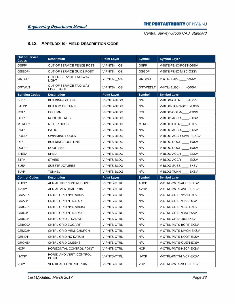
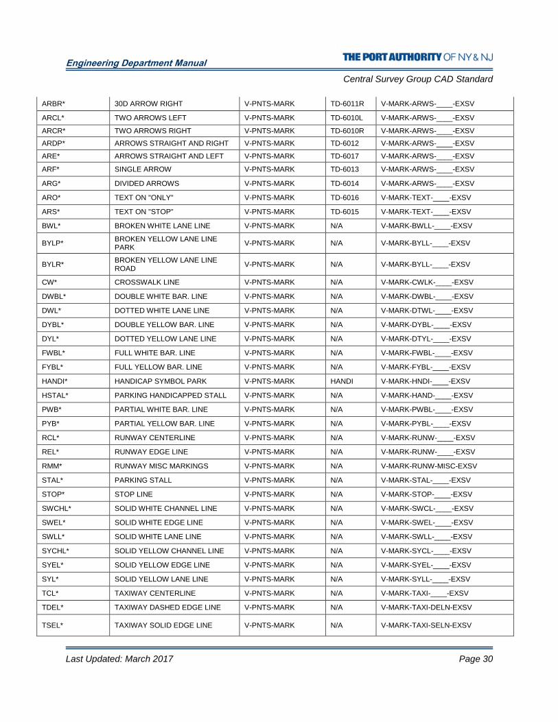
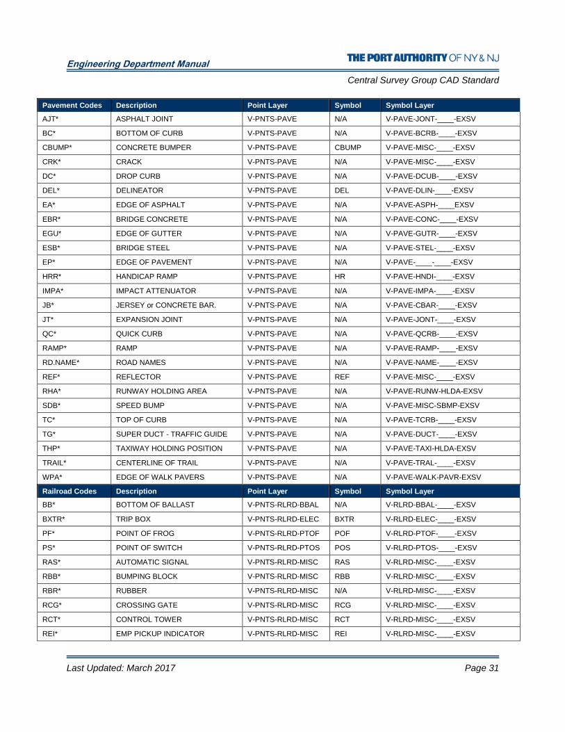
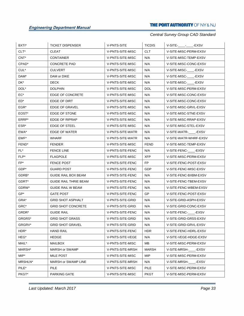
8.12 APPENDIX B - FIELD DESCRIPTION CODE
Out of Service Codes
Description Point Layer Symbol Symbol Layer
OSFP* OUT OF SERVICE FENCE POST V-PNTS-__OS OSFP V-SITE-FENC-POST-OSSV
OSGDP* OUT OF SERVICE GUIDE POST V-PNTS-__OS OSGDP V-SITE-FENC-MISC-OSSV
OSTLT* OUT OF SERVICE TAXI-WAY LIGHT
V-PNTS-__OS OSTWLT V-UTIL-ELEC-____-OSSV
OSTWLT* OUT OF SERVICE TAXI-WAY EDGE LIGHT
V-PNTS-__OS OSTWEDLT V-UTIL-ELEC-____-OSSV
Building Codes Description Point Layer Symbol Symbol Layer
BLD* BUILDING OUTLINE V-PNTS-BLDG N/A V-BLDG-OTLN-____-EXSV
BTUN* BOTTOM OF TUNNEL V-PNTS-BLDG N/A V-BLDG-TUNN-BOTT-EXSV
COL* COLUMN V-PNTS-BLDG COL V-BLDG-COLM-____-EXSV
DET* ROOF DETAILS V-PNTS-BLDG N/A V-BLDG-ACCR-____-EXSV
MTRHS* METER HOUSE V-PNTS-BLDG MTRHS V-BLDG-OTLN-____-EXSV
PAT* PATIO V-PNTS-BLDG N/A V-BLDG-ACCR-____-EXSV
POOL* SWIMMING POOLS V-PNTS-BLDG N/A V-BLDG-ACCR-SWMP-EXSV
RF* BUILDING ROOF LINE V-PNTS-BLDG N/A V-BLDG-ROOF-____-EXSV
ROOF* ROOF LINE V-PNTS-BLDG N/A V-BLDG-ROOF-____-EXSV
SHED* SHED V-PNTS-BLDG N/A V-BLDG-ACCR-____-EXSV
STR* STAIRS V-PNTS-BLDG N/A V-BLDG-ACCR-____-EXSV
SUB* SUBSTRUCTURES V-PNTS-BLDG N/A V-BLDG-SUBS-____-EXSV
TUN* TUNNEL V-PNTS-BLDG N/A V-BLDG-TUNN-____-EXSV
Control Codes Description Point Layer Symbol Symbol Layer
AHCP* AERIAL HORIZONTAL POINT V-PNTS-CTRL AHCP V-CTRL-PNTS-AHCP-EXSV
AVCP* AERIAL VERTICAL POINT V-PNTS-CTRL AVCP V-CTRL-PNTS-AVCP-EXSV
GR27E* CNTRL GRID NYE NAD27 V-PNTS-CTRL N/A V-CTRL-GRID-NY27-EXSV
GR27J* CNTRL GRID NJ NAD27 V-PNTS-CTRL N/A V-CTRL-GRID-NJ27-EXSV
GR83E* CNTRL GRID NYE NAD83 V-PNTS-CTRL N/A V-CTRL-GRID-NE83-EXSV
GR83J* CNTRL GRID NJ NAD83 V-PNTS-CTRL N/A V-CTRL-GRID-NJ83-EXSV
GR83LI* CNTRL GRID LI NAD83 V-PNTS-CTRL N/A V-CTRL-GRID-LI83-EXSV
GRBOG* CNTRL GRID BOGART V-PNTS-CTRL N/A V-CTRL-PNTS-BGRT-EXSV
GRMCH* CNTRL GRID MEM. CHURCH V-PNTS-CTRL N/A V-CTRL-PNTS-MMCH-EXSV
GRNDT* CNTRL GRID NO DATUM V-PNTS-CTRL N/A V-CTRL-PNTS-NODT-EXSV
GRQNS* CNTRL GRID QUEENS V-PNTS-CTRL N/A V-CTRL-PNTS-QUEN-EXSV
HCP* HORIZONTAL CONTROL POINT V-PNTS-CTRL HCP V-CTRL-PNTS-HSCP-EXSV
HVCP* HORIZ. AND VERT. CONTROL POINT
V-PNTS-CTRL HVCP V-CTRL-PNTS-HVCP-EXSV
VCP* VERTICAL CONTROL POINT V-PNTS-CTRL VCP V-CTRL-PNTS-VSCP-EXSV

Engineering Department Manual
Central Survey Group CAD Standard
Last Updated: March 2017 Page 29
Environmental Codes
Description Point Layer Symbol Symbol Layer
BH* BORE HOLE V-PNTS-ENVR-BORE BH V-ENVR-BORE-____-EXSV
EHZ* EDGE OF HAZARD V-PNTS-ENVR-HAZR N/A V-ENVR-HAZR-____-EXSV
EXW* EXTRACTION WELL V-PNTS-ENVR-MISC EXW V-ENVR-EXTW-____-EXSV
HDP* HYDROPUNCH V-PNTS-ENVR-MISC HDP V-ENVR-HYDP-____-EXSV
LCB* LEACHING BASIN V-PNTS-ENVR-MISC LCB V-ENVR-LEAB-____-EXSV
MWL* MONITORING WELL V-PNTS-ENVR-MONW MW V-ENVR-MONW-____-EXSV
PHR* EDGE OF PHRAGMITES V-PNTS-ENVR-PHRG N/A V-ENVR-PHRG-____-EXSV
SPT* SETTLING POINT V-PNTS-ENVR-SETP SPT V-ENVR-SETP-____-EXSV
WFL* WETLAND FLAG V-PNTS-ENVR-WETL WFL V-ENVR-WETL-____-EXSV
Hypsography Codes
Description Point Layer Symbol Symbol Layer
BS* BOTTOM OF SLOPE OR BANK V-PNTS-HYPS N/A V-HYPS-BOTT-____-EXSV
DEP-INDEX* DEPRESSION INDEX CONTOUR V-PNTS-HYPS N/A V-HYPS-INDX-DEPR-EXSV
DEP-INTER* DEPRESSION INTERMEDIATE CONTOUR
V-PNTS-HYPS N/A V-HYPS-INTR-DEPR-EXSV
D-O-INDEX* D-O INDEX CONTOUR V-PNTS-HYPS N/A V-HYPS-INDX-DOBS-EXSV
D-O-INTER* D-O INTERMEDIATE CONTOUR V-PNTS-HYPS N/A V-HYPS-INTR-DOBS-EXSV
DTM* DIGITAL TERRAIN MODEL V-PNTS-HYPS DTM V-HYPS-DTMP-____-EXSV
INDEX* INDEX CONTOUR V-PNTS-HYPS N/A V-HYPS-INDX-____-EXSV
INTER* INTERMEDIATE CONTOUR V-PNTS-HYPS N/A V-HYPS-INTR-____-EXSV
OBS-INDEX* OBS INDEX CONTOUR V-PNTS-HYPS N/A V-HYPS-INDX-DOBS-EXSV
OBS-INTER* OBS INTERMEDIATE CONTOUR V-PNTS-HYPS N/A V-HYPS-INTR-DOBS-EXSV
SSHT* SPOT SHOT V-PNTS-HYPS SSHT V-HYPS-SPOT-____-EXSV
TS* TOP OF SLOPE OR BANK V-PNTS-HYPS N/A V-HYPS-TOPS-____-EXSV
Legal Codes Description Point Layer Symbol Symbol Layer
EBH* BULKHEAD V-PNTS-LEGL N/A V-LEGL-BULK-____-EXSV
EPH* PIERHEAD V-PNTS-LEGL N/A V-LEGL-PIER-____-EXSV
LBLK* BULKHCSG LINE V-PNTS-LEGL N/A V-LEGL-BULK-____-EXSV
LEAS* EASMENT LINES V-PNTS-LEGL N/A V-LEGL-EASE-____-EXSV
LL* LEASE LINES V-PNTS-LEGL N/A V-LEGL-LEAS-____-EXSV
LPRH* PIERHEAD LINE V-PNTS-LEGL N/A V-LEGL-PIER-____-EXSV
PL* PROPERTY LINES V-PNTS-LEGL N/A V-LEGL-PROP-____-EXSV
TL* TENENT LINES V-PNTS-LEGL N/A V-LEGL-TENN-____-EXSV
Pavement Marking Codes
Description Point Layer Symbol Symbol Layer
APPM* APRON PAVEMENT MARKINGS V-PNTS-MARK N/A V-MARK-APRN-____-EXSV
ARAL* 90D ARROW LEFT V-PNTS-MARK TD-6009L V-MARK-ARWS-____-EXSV
ARAR* 90D ARROW RIGHT V-PNTS-MARK TD-6009R V-MARK-ARWS-____-EXSV
ARBL* 30D ARROW LEFT V-PNTS-MARK TD-6011L V-MARK-ARWS-____-EXSV
Engineering Department Manual
Central Survey Group CAD Standard
Last Updated: March 2017 Page 30
ARBR* 30D ARROW RIGHT V-PNTS-MARK TD-6011R V-MARK-ARWS-____-EXSV
ARCL* TWO ARROWS LEFT V-PNTS-MARK TD-6010L V-MARK-ARWS-____-EXSV
ARCR* TWO ARROWS RIGHT V-PNTS-MARK TD-6010R V-MARK-ARWS-____-EXSV
ARDP* ARROWS STRAIGHT AND RIGHT V-PNTS-MARK TD-6012 V-MARK-ARWS-____-EXSV
ARE* ARROWS STRAIGHT AND LEFT V-PNTS-MARK TD-6017 V-MARK-ARWS-____-EXSV
ARF* SINGLE ARROW V-PNTS-MARK TD-6013 V-MARK-ARWS-____-EXSV
ARG* DIVIDED ARROWS V-PNTS-MARK TD-6014 V-MARK-ARWS-____-EXSV
ARO* TEXT ON "ONLY" V-PNTS-MARK TD-6016 V-MARK-TEXT-____-EXSV
ARS* TEXT ON "STOP" V-PNTS-MARK TD-6015 V-MARK-TEXT-____-EXSV
BWL* BROKEN WHITE LANE LINE V-PNTS-MARK N/A V-MARK-BWLL-____-EXSV
BYLP* BROKEN YELLOW LANE LINE PARK
V-PNTS-MARK N/A V-MARK-BYLL-____-EXSV
BYLR* BROKEN YELLOW LANE LINE ROAD
V-PNTS-MARK N/A V-MARK-BYLL-____-EXSV
CW* CROSSWALK LINE V-PNTS-MARK N/A V-MARK-CWLK-____-EXSV
DWBL* DOUBLE WHITE BAR. LINE V-PNTS-MARK N/A V-MARK-DWBL-____-EXSV
DWL* DOTTED WHITE LANE LINE V-PNTS-MARK N/A V-MARK-DTWL-____-EXSV
DYBL* DOUBLE YELLOW BAR. LINE V-PNTS-MARK N/A V-MARK-DYBL-____-EXSV
DYL* DOTTED YELLOW LANE LINE V-PNTS-MARK N/A V-MARK-DTYL-____-EXSV
FWBL* FULL WHITE BAR. LINE V-PNTS-MARK N/A V-MARK-FWBL-____-EXSV
FYBL* FULL YELLOW BAR. LINE V-PNTS-MARK N/A V-MARK-FYBL-____-EXSV
HANDI* HANDICAP SYMBOL PARK V-PNTS-MARK HANDI V-MARK-HNDI-____-EXSV
HSTAL* PARKING HANDICAPPED STALL V-PNTS-MARK N/A V-MARK-HAND-____-EXSV
PWB* PARTIAL WHITE BAR. LINE V-PNTS-MARK N/A V-MARK-PWBL-____-EXSV
PYB* PARTIAL YELLOW BAR. LINE V-PNTS-MARK N/A V-MARK-PYBL-____-EXSV
RCL* RUNWAY CENTERLINE V-PNTS-MARK N/A V-MARK-RUNW-____-EXSV
REL* RUNWAY EDGE LINE V-PNTS-MARK N/A V-MARK-RUNW-____-EXSV
RMM* RUNWAY MISC MARKINGS V-PNTS-MARK N/A V-MARK-RUNW-MISC-EXSV
STAL* PARKING STALL V-PNTS-MARK N/A V-MARK-STAL-____-EXSV
STOP* STOP LINE V-PNTS-MARK N/A V-MARK-STOP-____-EXSV
SWCHL* SOLID WHITE CHANNEL LINE V-PNTS-MARK N/A V-MARK-SWCL-____-EXSV
SWEL* SOLID WHITE EDGE LINE V-PNTS-MARK N/A V-MARK-SWEL-____-EXSV
SWLL* SOLID WHITE LANE LINE V-PNTS-MARK N/A V-MARK-SWLL-____-EXSV
SYCHL* SOLID YELLOW CHANNEL LINE V-PNTS-MARK N/A V-MARK-SYCL-____-EXSV
SYEL* SOLID YELLOW EDGE LINE V-PNTS-MARK N/A V-MARK-SYEL-____-EXSV
SYL* SOLID YELLOW LANE LINE V-PNTS-MARK N/A V-MARK-SYLL-____-EXSV
TCL* TAXIWAY CENTERLINE V-PNTS-MARK N/A V-MARK-TAXI-____-EXSV
TDEL* TAXIWAY DASHED EDGE LINE V-PNTS-MARK N/A V-MARK-TAXI-DELN-EXSV
TSEL* TAXIWAY SOLID EDGE LINE V-PNTS-MARK N/A V-MARK-TAXI-SELN-EXSV
Engineering Department Manual
Central Survey Group CAD Standard
Last Updated: March 2017 Page 31
Pavement Codes Description Point Layer Symbol Symbol Layer
AJT* ASPHALT JOINT V-PNTS-PAVE N/A V-PAVE-JONT-____-EXSV
BC* BOTTOM OF CURB V-PNTS-PAVE N/A V-PAVE-BCRB-____-EXSV
CBUMP* CONCRETE BUMPER V-PNTS-PAVE CBUMP V-PAVE-MISC-____-EXSV
CRK* CRACK V-PNTS-PAVE N/A V-PAVE-MISC-____-EXSV
DC* DROP CURB V-PNTS-PAVE N/A V-PAVE-DCUB-____-EXSV
DEL* DELINEATOR V-PNTS-PAVE DEL V-PAVE-DLIN-____-EXSV
EA* EDGE OF ASPHALT V-PNTS-PAVE N/A V-PAVE-ASPH-____EXSV
EBR* BRIDGE CONCRETE V-PNTS-PAVE N/A V-PAVE-CONC-____-EXSV
EGU* EDGE OF GUTTER V-PNTS-PAVE N/A V-PAVE-GUTR-____-EXSV
ESB* BRIDGE STEEL V-PNTS-PAVE N/A V-PAVE-STEL-____-EXSV
EP* EDGE OF PAVEMENT V-PNTS-PAVE N/A V-PAVE-____-____-EXSV
HRR* HANDICAP RAMP V-PNTS-PAVE HR V-PAVE-HNDI-____-EXSV
IMPA* IMPACT ATTENUATOR V-PNTS-PAVE N/A V-PAVE-IMPA-____-EXSV
JB* JERSEY or CONCRETE BAR. V-PNTS-PAVE N/A V-PAVE-CBAR-____-EXSV
JT* EXPANSION JOINT V-PNTS-PAVE N/A V-PAVE-JONT-____-EXSV
QC* QUICK CURB V-PNTS-PAVE N/A V-PAVE-QCRB-____-EXSV
RAMP* RAMP V-PNTS-PAVE N/A V-PAVE-RAMP-____-EXSV
RD.NAME* ROAD NAMES V-PNTS-PAVE N/A V-PAVE-NAME-____-EXSV
REF* REFLECTOR V-PNTS-PAVE REF V-PAVE-MISC-____-EXSV
RHA* RUNWAY HOLDING AREA V-PNTS-PAVE N/A V-PAVE-RUNW-HLDA-EXSV
SDB* SPEED BUMP V-PNTS-PAVE N/A V-PAVE-MISC-SBMP-EXSV
TC* TOP OF CURB V-PNTS-PAVE N/A V-PAVE-TCRB-____-EXSV
TG* SUPER DUCT - TRAFFIC GUIDE V-PNTS-PAVE N/A V-PAVE-DUCT-____-EXSV
THP* TAXIWAY HOLDING POSITION V-PNTS-PAVE N/A V-PAVE-TAXI-HLDA-EXSV
TRAIL* CENTERLINE OF TRAIL V-PNTS-PAVE N/A V-PAVE-TRAL-____-EXSV
WPA* EDGE OF WALK PAVERS V-PNTS-PAVE N/A V-PAVE-WALK-PAVR-EXSV
Railroad Codes Description Point Layer Symbol Symbol Layer
BB* BOTTOM OF BALLAST V-PNTS-RLRD-BBAL N/A V-RLRD-BBAL-____-EXSV
BXTR* TRIP BOX V-PNTS-RLRD-ELEC BXTR V-RLRD-ELEC-____-EXSV
PF* POINT OF FROG V-PNTS-RLRD-PTOF POF V-RLRD-PTOF-____-EXSV
PS* POINT OF SWITCH V-PNTS-RLRD-PTOS POS V-RLRD-PTOS-____-EXSV
RAS* AUTOMATIC SIGNAL V-PNTS-RLRD-MISC RAS V-RLRD-MISC-____-EXSV
RBB* BUMPING BLOCK V-PNTS-RLRD-MISC RBB V-RLRD-MISC-____-EXSV
RBR* RUBBER V-PNTS-RLRD-MISC N/A V-RLRD-MISC-____-EXSV
RCG* CROSSING GATE V-PNTS-RLRD-MISC RCG V-RLRD-MISC-____-EXSV
RCT* CONTROL TOWER V-PNTS-RLRD-MISC RCT V-RLRD-MISC-____-EXSV
REI* EMP PICKUP INDICATOR V-PNTS-RLRD-MISC REI V-RLRD-MISC-____-EXSV

Engineering Department Manual
Central Survey Group CAD Standard
Last Updated: March 2017 Page 32
REP* EMP PICKUP PLAT V-PNTS-RLRD-MISC REP V-RLRD-MISC-____-EXSV
RIMP* IMPEDENCE BOND V-PNTS-RLRD-MISC RIMP V-RLRD-MISC-____-EXSV
RIS* INTERLOCKING SIGNAL V-PNTS-RLRD-MISC RIS V-RLRD-MISC-____-EXSV
RPR* RAILROAD POWER RAIL V-PNTS-RLRD-POWR N/A V-RLRD-POWR-____-EXSV
RPS* STOP POWER RAIL V-PNTS-RLRD-MISC RPS V-RLRD-MISC-____-EXSV
RQR* ROUTE REQUEST V-PNTS-RLRD-MISC RQR V-RLRD-MISC-____-EXSV
RR* TRACK CENTERLINE V-PNTS-RLRD-CLIN N/A V-RLRD-CLIN-____-EXSV
RSB* SMASHBOARD V-PNTS-RLRD-MISC RSB V-RLRD-MISC-____-EXSV
RST* STOP ON TRACK V-PNTS-RLRD-MISC N/A V-RLRD-MISC-____-EXSV
RTI* TRACK INDICATOR V-PNTS-RLRD-MISC RTI V-RLRD-MISC-____-EXSV
SB* SWITCH BOX V-PNTS-RLRD-MISC SB V-RLRD-MISC-____-EXSV
TB* TOP OF BALLAST V-PNTS-RLRD-TBAL N/A V-RLRD-TBAL-____-EXSV
TRACK* RAILROAD TRACK LINE V-PNTS-RLRD-TRCK N/A V-RLRD-TRCK-____-EXSV
Signage Codes Description Point Layer Symbol Symbol Layer
GDS* SIGN GUIDE V-PNTS-SIGN SN V-SIGN-GUID-____-EXSV
INF* SIGN INFO V-PNTS-SIGN SN V-SIGN-INFO-____-EXSV
OSSN* OUT OF SERVICE SIGN POST V-PNTS-SIGN SN V-SIGN-GNRL-____-OSSV
REG* SIGN REGULATORY V-PNTS-SIGN SN V-SIGN-REGU-____-EXSV
RWSN* SIGN RUNWAY V-PNTS-SIGN RWSN V-SIGN-RUNW-____-EXSV
SN* SIGN GENERAL V-PNTS-SIGN SN V-SIGN-GNRL-____-EXSV
SNOB* SIGN OBJECT MARKER V-PNTS-SIGN SN V-SIGN-OBJM-____-EXSV
SNP* SIGN POST V-PNTS-SIGN SNP V-SIGN-GNRL-____-EXSV
VMS* SIGN VMS V-PNTS-SIGN VMS V-SIGN-VMSS-____-EXSV
WAR* SIGN WARNING V-PNTS-SIGN SN V-SIGN-WARN-____-EXSV
Sitework Codes Description Point Layer Symbol Symbol Layer
ABT* ABUTMENT V-PNTS-SITE-WALL N/A V-SITE-WALL-STRU-EXSV
AF* ATHLETIC FIELD V-PNTS-SITE-MISC N/A V-SITE-MISC-____-EXSV
ANT* ANTENNA V-PNTS-SITE-MISC ANT V-SITE-MISC-PERM-EXSV
BF* BLAST FENCE V-PNTS-SITE-FENC N/A V-SITE-FENC-BLST-EXSV
BNCH* PARK BENCH V-PNTS-SITE-MISC BNCH V-SITE-MISC-PERM-EXSV
BOL* BOLLARD V-PNTS-SITE-MISC BOL V-SITE-MISC-PERM-EXSV
BRLS* SAND FILLED BARREL V-PNTS-SITE-MISC BRLS V-SITE-MISC-BARL-EXSV
BRMP* BOAT RAMP V-PNTS-SITE-WALL N/A V-SITE-WALL-MRNE-EXSV
BUC* CONIFEROUS BUSH V-PNTS-SITE-VEGE BUC V-SITE-VEGE-TREE-EXSV
BUD* DECIDUOS BUSH V-PNTS-SITE-VEGE BUD V-SITE-VEGE-TREE-EXSV
BUOY* BUOY V-PNTS-SITE-MISC BUOY V-SITE-MISC-PERM-EXSV
BUU* UNKNOWN BUSH V-PNTS-SITE-VEGE BUU V-SITE-VEGE-TREE-EXSV
BXS* STEEL BOX V-PNTS-SITE-MISC BXS V-SITE-MISC-PERM-EXSV
BXSC* BOX W/ STEEL COVER V-PNTS-SITE-MISC BXSC V-SITE-MISC-PERM-EXSV
Engineering Department Manual
Central Survey Group CAD Standard
Last Updated: March 2017 Page 33
BXTI* TICKET DISPENSER V-PNTS-SITE TICDIS V-SITE-____-____-EXSV
CLT* CLEAT V-PNTS-SITE-MISC CLT V-SITE-MISC-PERM-EXSV
CNT* CONTAINER V-PNTS-SITE-MISC N/A V-SITE-MISC-TEMP-EXSV
CPAD* CONCRETE PAD V-PNTS-SITE-MISC N/A V-SITE-MISC-CONC-EXSV
CUL* CULVERT V-PNTS-SITE-MISC N/A V-SITE-MISC-____-EXSV
DAM* DAM or DIKE V-PNTS-SITE-MISC N/A V-SITE-MISC-____-EXSV
DK* DECK V-PNTS-SITE-MISC N/A V-SITE-MISC-____-EXSV
DOL* DOLPHIN V-PNTS-SITE-MISC DOL V-SITE-MISC-PERM-EXSV
EC* EDGE OF CONCRETE V-PNTS-SITE-MISC N/A V-SITE-MISC-CONC-EXSV
ED* EDGE OF DIRT V-PNTS-SITE-MISC N/A V-SITE-MISC-CONC-EXSV
EGR* EDGE OF GRAVEL V-PNTS-SITE-MISC N/A V-SITE-MISC-GRVL-EXSV
EOST* EDGE OF STONE V-PNTS-SITE-MISC N/A V-SITE-MISC-STNE-EXSV
ERRP* EDGE OF RIPRAP V-PNTS-SITE-MISC N/A V-SITE-MISC-RRAP-EXSV
ESR* EDGE OF STEEL V-PNTS-SITE-MISC N/A V-SITE-MISC-STEL-EXSV
EWA* EDGE OF WATER V-PNTS-SITE-WATR N/A V-SITE-WATR-____-EXSV
EWF* WHARF V-PNTS-SITE-WATR N/A V-SITE-WATR-WHRF-EXSV
FEND* FENDER V-PNTS-SITE-MISC FEND V-SITE-MISC-TEMP-EXSV
FL* FENCE LINE V-PNTS-SITE-FENC N/A V-SITE-FENC-____-EXSV
FLP* FLAGPOLE V-PNTS-SITE-MISC XFP V-SITE-MISC-PERM-EXSV
FP* FENCE POST V-PNTS-SITE-FENC FP V-SITE-FENC-POST-EXSV
GDP* GUARD POST V-PNTS-SITE-FENC GDP V-SITE-FENC-MISC-EXSV
GDRB* GUIDE RAIL BOX BEAM V-PNTS-SITE-FENC N/A V-SITE-FENC-BXBM-EXSV
GDRT* GUIDE RAIL THRIE BEAM V-PNTS-SITE-FENC N/A V-SITE-FENC-TBEM-EXSV
GDRW* GUIDE RAIL W BEAM V-PNTS-SITE-FENC N/A V-SITE-FENC-WBEM-EXSV
GP* GATE POST V-PNTS-SITE-FENC GP V-SITE-FENC-POST-EXSV
GRA* GRID SHOT ASPHALT V-PNTS-SITE-GRID N/A V-SITE-GRID-ASPH-EXSV
GRC* GRID SHOT CONCRETE V-PNTS-SITE-GRID N/A V-SITE-GRID-CONC-EXSV
GRDR* GUIDE RAIL V-PNTS-SITE-FENC N/A V-SITE-FENC-____-EXSV
GRGRS* GRID SHOT GRASS V-PNTS-SITE-GRID N/A V-SITE-GRID-GRSS-EXSV
GRGRV* GRID SHOT GRAVEL V-PNTS-SITE-GRID N/A V-SITE-GRID-GRVL-EXSV
HDR* HAND RAIL V-PNTS-SITE-FENC HDR V-SITE-FENC-HDRL-EXSV
HEG* HEDGE V-PNTS-SITE-VEGE N/A V-SITE-VEGE-HDGE-EXSV
MAIL* MAILBOX V-PNTS-SITE-MISC MB V-SITE-MISC-PERM-EXSV
MARSH* MARSH or SWAMP V-PNTS-SITE-MRSH MARSH V-SITE-MRSH-____-EXSV
MIP* MILE POST V-PNTS-SITE-MISC MIP V-SITE-MISC-PERM-EXSV
MRSHLN* MARSH or SWAMP LINE V-PNTS-SITE-MRSH N/A V-SITE-MRSH-____-EXSV
PILE* PILE V-PNTS-SITE-MISC PILE V-SITE-MISC-PERM-EXSV
PKGT* PARKING GATE V-PNTS-SITE-MISC PKGT V-SITE-MISC-PERM-EXSV
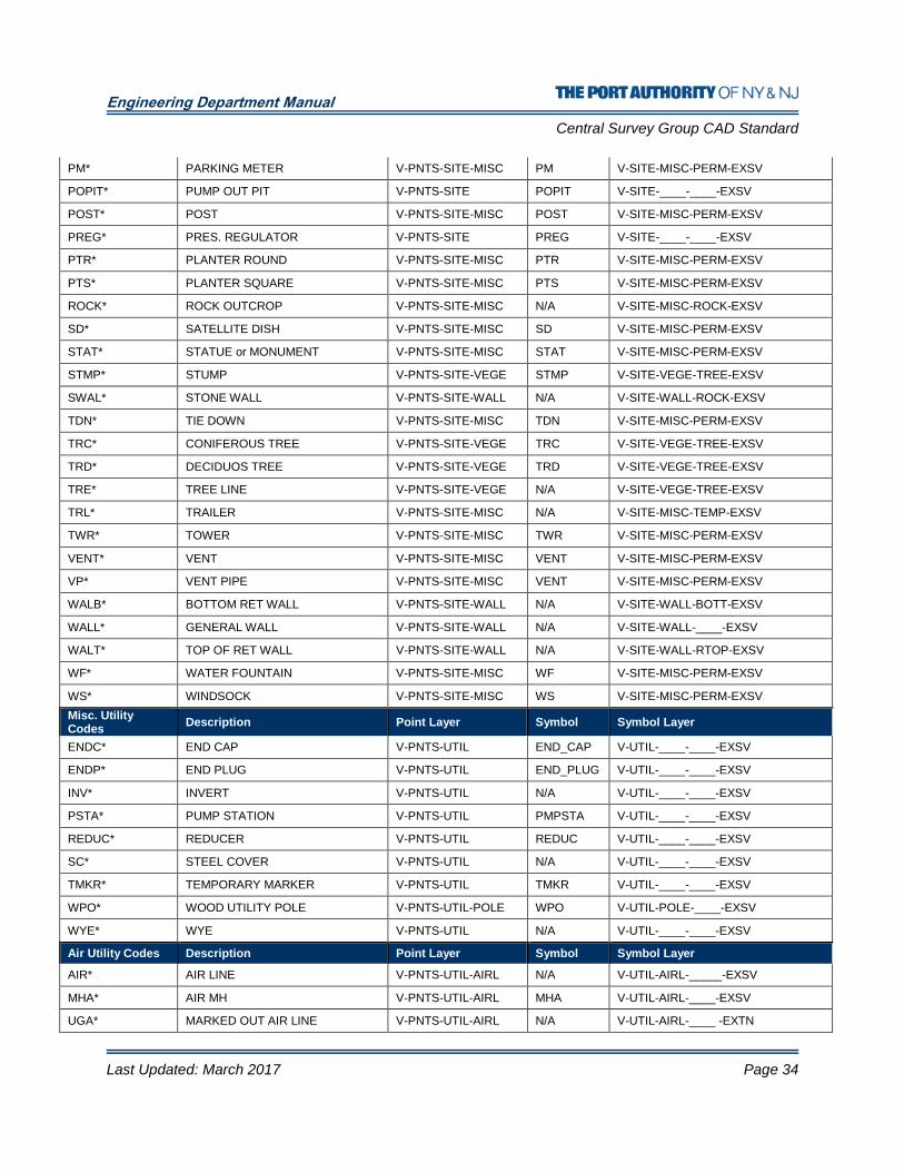
Engineering Department Manual
Central Survey Group CAD Standard
Last Updated: March 2017 Page 34
PM* PARKING METER V-PNTS-SITE-MISC PM V-SITE-MISC-PERM-EXSV
POPIT* PUMP OUT PIT V-PNTS-SITE POPIT V-SITE-____-____-EXSV
POST* POST V-PNTS-SITE-MISC POST V-SITE-MISC-PERM-EXSV
PREG* PRES. REGULATOR V-PNTS-SITE PREG V-SITE-____-____-EXSV
PTR* PLANTER ROUND V-PNTS-SITE-MISC PTR V-SITE-MISC-PERM-EXSV
PTS* PLANTER SQUARE V-PNTS-SITE-MISC PTS V-SITE-MISC-PERM-EXSV
ROCK* ROCK OUTCROP V-PNTS-SITE-MISC N/A V-SITE-MISC-ROCK-EXSV
SD* SATELLITE DISH V-PNTS-SITE-MISC SD V-SITE-MISC-PERM-EXSV
STAT* STATUE or MONUMENT V-PNTS-SITE-MISC STAT V-SITE-MISC-PERM-EXSV
STMP* STUMP V-PNTS-SITE-VEGE STMP V-SITE-VEGE-TREE-EXSV
SWAL* STONE WALL V-PNTS-SITE-WALL N/A V-SITE-WALL-ROCK-EXSV
TDN* TIE DOWN V-PNTS-SITE-MISC TDN V-SITE-MISC-PERM-EXSV
TRC* CONIFEROUS TREE V-PNTS-SITE-VEGE TRC V-SITE-VEGE-TREE-EXSV
TRD* DECIDUOS TREE V-PNTS-SITE-VEGE TRD V-SITE-VEGE-TREE-EXSV
TRE* TREE LINE V-PNTS-SITE-VEGE N/A V-SITE-VEGE-TREE-EXSV
TRL* TRAILER V-PNTS-SITE-MISC N/A V-SITE-MISC-TEMP-EXSV
TWR* TOWER V-PNTS-SITE-MISC TWR V-SITE-MISC-PERM-EXSV
VENT* VENT V-PNTS-SITE-MISC VENT V-SITE-MISC-PERM-EXSV
VP* VENT PIPE V-PNTS-SITE-MISC VENT V-SITE-MISC-PERM-EXSV
WALB* BOTTOM RET WALL V-PNTS-SITE-WALL N/A V-SITE-WALL-BOTT-EXSV
WALL* GENERAL WALL V-PNTS-SITE-WALL N/A V-SITE-WALL-____-EXSV
WALT* TOP OF RET WALL V-PNTS-SITE-WALL N/A V-SITE-WALL-RTOP-EXSV
WF* WATER FOUNTAIN V-PNTS-SITE-MISC WF V-SITE-MISC-PERM-EXSV
WS* WINDSOCK V-PNTS-SITE-MISC WS V-SITE-MISC-PERM-EXSV
Misc. Utility Codes
Description Point Layer Symbol Symbol Layer
ENDC* END CAP V-PNTS-UTIL END_CAP V-UTIL-____-____-EXSV
ENDP* END PLUG V-PNTS-UTIL END_PLUG V-UTIL-____-____-EXSV
INV* INVERT V-PNTS-UTIL N/A V-UTIL-____-____-EXSV
PSTA* PUMP STATION V-PNTS-UTIL PMPSTA V-UTIL-____-____-EXSV
REDUC* REDUCER V-PNTS-UTIL REDUC V-UTIL-____-____-EXSV
SC* STEEL COVER V-PNTS-UTIL N/A V-UTIL-____-____-EXSV
TMKR* TEMPORARY MARKER V-PNTS-UTIL TMKR V-UTIL-____-____-EXSV
WPO* WOOD UTILITY POLE V-PNTS-UTIL-POLE WPO V-UTIL-POLE-____-EXSV
WYE* WYE V-PNTS-UTIL N/A V-UTIL-____-____-EXSV
Air Utility Codes Description Point Layer Symbol Symbol Layer
AIR* AIR LINE V-PNTS-UTIL-AIRL N/A V-UTIL-AIRL-_____-EXSV
MHA* AIR MH V-PNTS-UTIL-AIRL MHA V-UTIL-AIRL-____-EXSV
UGA* MARKED OUT AIR LINE V-PNTS-UTIL-AIRL N/A V-UTIL-AIRL-____ -EXTN
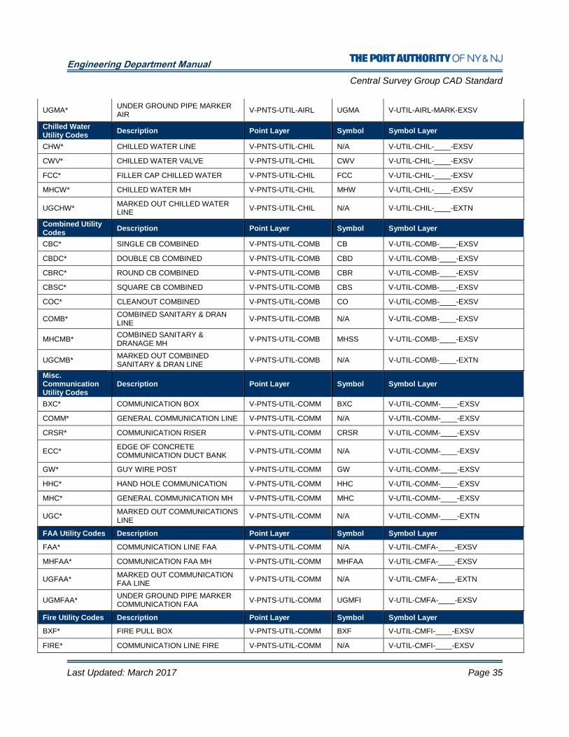
Engineering Department Manual
Central Survey Group CAD Standard
Last Updated: March 2017 Page 35
UGMA* UNDER GROUND PIPE MARKER AIR
V-PNTS-UTIL-AIRL UGMA V-UTIL-AIRL-MARK-EXSV
Chilled Water Utility Codes
Description Point Layer Symbol Symbol Layer
CHW* CHILLED WATER LINE V-PNTS-UTIL-CHIL N/A V-UTIL-CHIL-____-EXSV
CWV* CHILLED WATER VALVE V-PNTS-UTIL-CHIL CWV V-UTIL-CHIL-____-EXSV
FCC* FILLER CAP CHILLED WATER V-PNTS-UTIL-CHIL FCC V-UTIL-CHIL-____-EXSV
MHCW* CHILLED WATER MH V-PNTS-UTIL-CHIL MHW V-UTIL-CHIL-____-EXSV
UGCHW* MARKED OUT CHILLED WATER LINE
V-PNTS-UTIL-CHIL N/A V-UTIL-CHIL-____-EXTN
Combined Utility Codes
Description Point Layer Symbol Symbol Layer
CBC* SINGLE CB COMBINED V-PNTS-UTIL-COMB CB V-UTIL-COMB-____-EXSV
CBDC* DOUBLE CB COMBINED V-PNTS-UTIL-COMB CBD V-UTIL-COMB-____-EXSV
CBRC* ROUND CB COMBINED V-PNTS-UTIL-COMB CBR V-UTIL-COMB-____-EXSV
CBSC* SQUARE CB COMBINED V-PNTS-UTIL-COMB CBS V-UTIL-COMB-____-EXSV
COC* CLEANOUT COMBINED V-PNTS-UTIL-COMB CO V-UTIL-COMB-____-EXSV
COMB* COMBINED SANITARY & DRAN LINE
V-PNTS-UTIL-COMB N/A V-UTIL-COMB-____-EXSV
MHCMB* COMBINED SANITARY & DRANAGE MH
V-PNTS-UTIL-COMB MHSS V-UTIL-COMB-____-EXSV
UGCMB* MARKED OUT COMBINED SANITARY & DRAN LINE
V-PNTS-UTIL-COMB N/A V-UTIL-COMB-____-EXTN
Misc. Communication Utility Codes
Description Point Layer Symbol Symbol Layer
BXC* COMMUNICATION BOX V-PNTS-UTIL-COMM BXC V-UTIL-COMM-____-EXSV
COMM* GENERAL COMMUNICATION LINE V-PNTS-UTIL-COMM N/A V-UTIL-COMM-____-EXSV
CRSR* COMMUNICATION RISER V-PNTS-UTIL-COMM CRSR V-UTIL-COMM-____-EXSV
ECC* EDGE OF CONCRETE COMMUNICATION DUCT BANK
V-PNTS-UTIL-COMM N/A V-UTIL-COMM-____-EXSV
GW* GUY WIRE POST V-PNTS-UTIL-COMM GW V-UTIL-COMM-____-EXSV
HHC* HAND HOLE COMMUNICATION V-PNTS-UTIL-COMM HHC V-UTIL-COMM-____-EXSV
MHC* GENERAL COMMUNICATION MH V-PNTS-UTIL-COMM MHC V-UTIL-COMM-____-EXSV
UGC* MARKED OUT COMMUNICATIONS LINE
V-PNTS-UTIL-COMM N/A V-UTIL-COMM-____-EXTN
FAA Utility Codes Description Point Layer Symbol Symbol Layer
FAA* COMMUNICATION LINE FAA V-PNTS-UTIL-COMM N/A V-UTIL-CMFA-____-EXSV
MHFAA* COMMUNICATION FAA MH V-PNTS-UTIL-COMM MHFAA V-UTIL-CMFA-____-EXSV
UGFAA* MARKED OUT COMMUNICATION FAA LINE
V-PNTS-UTIL-COMM N/A V-UTIL-CMFA-____-EXTN
UGMFAA* UNDER GROUND PIPE MARKER COMMUNICATION FAA
V-PNTS-UTIL-COMM UGMFI V-UTIL-CMFA-____-EXSV
Fire Utility Codes Description Point Layer Symbol Symbol Layer
BXF* FIRE PULL BOX V-PNTS-UTIL-COMM BXF V-UTIL-CMFI-____-EXSV
FIRE* COMMUNICATION LINE FIRE V-PNTS-UTIL-COMM N/A V-UTIL-CMFI-____-EXSV

Engineering Department Manual
Central Survey Group CAD Standard
Last Updated: March 2017 Page 36
MHFIRE* COMMUNICATION FIRE MH V-PNTS-UTIL-COMM MHFI V-UTIL-CMFI-____-EXSV
UGFI* MARKED OUT COMMUNICATION FIRE LINE
V-PNTS-UTIL-COMM N/A V-UTIL-CMFI-____-EXTN
UGMFI* UNDER GROUND PIPE MARKER COMMUNICATION FIRE
V-PNTS-UTIL-COMM UGMFI V-UTIL-CMFI-____-EXSV
WPF* WOOD POLE W/ FIRE BOX V-PNTS-UTIL-COMM WPF V-UTIL-CMFI-____-EXSV
Fiber Optic Utility Codes
Description Point Layer Symbol Symbol Layer
FOC* FIBER OPTIC CABLE V-PNTS-UTIL-COMM N/A V-UTIL-CMFO-____-EXSV
UGFOC* MARKED OUT COMMUNICATION FIBER OPTIC LINE
V-PNTS-UTIL-COMM N/A V-UTIL-CMFO-____-EXTN
UGMFOC* UNDER GROUND PIPE MARKER COMMUNICATION FIBER OPTIC
V-PNTS-UTIL-COMM UGMFO V-UTIL-CMFO-____-EXSV
Security Utility Codes
Description Point Layer Symbol Symbol Layer
MHSEC* COMMUNICATION MH SECURITY V-PNTS-UTIL-COMM MHSC V-UTIL-CMSC-____-EXSV
SEC* COMMUNICATION LINE SECURITY
V-PNTS-UTIL-COMM N/A V-UTIL-CMSC-____-EXSV
UGMSC* UNDER GROUND PIPE MARKER COMMUNICATIONS SECURITY
V-PNTS-UTIL-COMM UGMC V-UTIL-CMSC-____ -EXSV
UGSE* MARKED OUT COMMUNICATION SECURITY LINE
V-PNTS-UTIL-COMM N/A V-UTIL-CMSC-____-EXTN
Telephone Utility Codes
Description Point Layer Symbol Symbol Layer
BXT* TELEPHONE BOX V-PNTS-UTIL-COMM BXT V-UTIL-CMTE-____-EXSV
MHT* COMMUNICATION MH TELEPHONE
V-PNTS-UTIL-COMM MHT V-UTIL-CMTE-____-EXSV
PB* PHONE BOOTH V-PNTS-UTIL-COMM PB V-UTIL-CMTE-____-EXSV
PP* PHONE POST V-PNTS-UTIL-COMM PP V-UTIL-CMTE-____-EXSV
TEL* COMMUNICATION LINE TELEPHONE
V-PNTS-UTIL-COMM N/A V-UTIL-CMTE-____-EXSV
UGMTE* UNDER GROUND PIPE MARKER TELEPHONE
V-PNTS-UTIL-COMM UGMTE V-UTIL-CMTE-____-EXSV
UGTE* MARKED OUT TELEPHONE LINE V-PNTS-UTIL-COMM N/A V-UTIL-CMTE-____-EXTN
Traffic Utility Codes
Description Point Layer Symbol Symbol Layer
BXTC* TRAFFIC SIGNAL BOX V-PNTS-UTIL-COMM BXTC V-UTIL-CMTR-____-EXSV
MHTC* COMMUNICATION MH TRAFFIC V-PNTS-UTIL-COMM MHTC V-UTIL-CMTR-____-EXSV
MTL* METAL TRAFFIC SIGNAL V-PNTS-UTIL-COMM MTL V-UTIL-CMTR-____-EXSV
SPLBX* SPLICE BOX V-PNTS-UTIL-COMM SPLBX V-UTIL-CMTR-____-EXSV
TOLB* TOLL BOOTH V-PNTS-UTIL-COMM N/A V-UTIL-CMTR-____-EXSV
TRAF* COMMUNICATION TRAFFIC LINE V-PNTS-UTIL-COMM N/A V-UTIL-CMTR-____-EXSV
TRFS* TRAFFIC SENSOR V-PNTS-UTIL-COMM TRFS V-UTIL-CMTR-____-EXSV
UGMTR* UNDER GROUND PIPE MARKER TRAFFIC
V-PNTS-UTIL-COMM UGMTR V-UTIL-CMTR-____-EXSV
UGTR* MARKED OUT TRAFFIC LINE V-PNTS-UTIL-COMM N/A V-UTIL-CMTR-____-EXTN
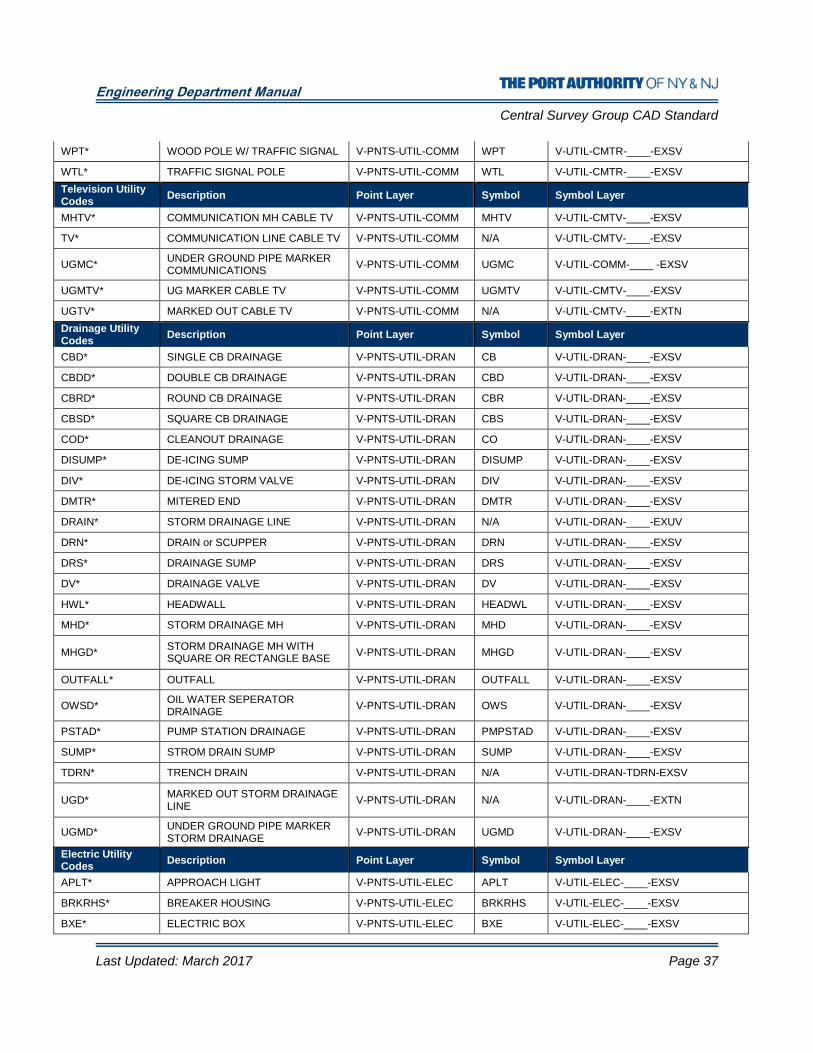
Engineering Department Manual
Central Survey Group CAD Standard
Last Updated: March 2017 Page 37
WPT* WOOD POLE W/ TRAFFIC SIGNAL V-PNTS-UTIL-COMM WPT V-UTIL-CMTR-____-EXSV
WTL* TRAFFIC SIGNAL POLE V-PNTS-UTIL-COMM WTL V-UTIL-CMTR-____-EXSV
Television Utility Codes
Description Point Layer Symbol Symbol Layer
MHTV* COMMUNICATION MH CABLE TV V-PNTS-UTIL-COMM MHTV V-UTIL-CMTV-____-EXSV
TV* COMMUNICATION LINE CABLE TV V-PNTS-UTIL-COMM N/A V-UTIL-CMTV-____-EXSV
UGMC* UNDER GROUND PIPE MARKER COMMUNICATIONS
V-PNTS-UTIL-COMM UGMC V-UTIL-COMM-____ -EXSV
UGMTV* UG MARKER CABLE TV V-PNTS-UTIL-COMM UGMTV V-UTIL-CMTV-____-EXSV
UGTV* MARKED OUT CABLE TV V-PNTS-UTIL-COMM N/A V-UTIL-CMTV-____-EXTN
Drainage Utility Codes
Description Point Layer Symbol Symbol Layer
CBD* SINGLE CB DRAINAGE V-PNTS-UTIL-DRAN CB V-UTIL-DRAN-____-EXSV
CBDD* DOUBLE CB DRAINAGE V-PNTS-UTIL-DRAN CBD V-UTIL-DRAN-____-EXSV
CBRD* ROUND CB DRAINAGE V-PNTS-UTIL-DRAN CBR V-UTIL-DRAN-____-EXSV
CBSD* SQUARE CB DRAINAGE V-PNTS-UTIL-DRAN CBS V-UTIL-DRAN-____-EXSV
COD* CLEANOUT DRAINAGE V-PNTS-UTIL-DRAN CO V-UTIL-DRAN-____-EXSV
DISUMP* DE-ICING SUMP V-PNTS-UTIL-DRAN DISUMP V-UTIL-DRAN-____-EXSV
DIV* DE-ICING STORM VALVE V-PNTS-UTIL-DRAN DIV V-UTIL-DRAN-____-EXSV
DMTR* MITERED END V-PNTS-UTIL-DRAN DMTR V-UTIL-DRAN-____-EXSV
DRAIN* STORM DRAINAGE LINE V-PNTS-UTIL-DRAN N/A V-UTIL-DRAN-____-EXUV
DRN* DRAIN or SCUPPER V-PNTS-UTIL-DRAN DRN V-UTIL-DRAN-____-EXSV
DRS* DRAINAGE SUMP V-PNTS-UTIL-DRAN DRS V-UTIL-DRAN-____-EXSV
DV* DRAINAGE VALVE V-PNTS-UTIL-DRAN DV V-UTIL-DRAN-____-EXSV
HWL* HEADWALL V-PNTS-UTIL-DRAN HEADWL V-UTIL-DRAN-____-EXSV
MHD* STORM DRAINAGE MH V-PNTS-UTIL-DRAN MHD V-UTIL-DRAN-____-EXSV
MHGD* STORM DRAINAGE MH WITH SQUARE OR RECTANGLE BASE
V-PNTS-UTIL-DRAN MHGD V-UTIL-DRAN-____-EXSV
OUTFALL* OUTFALL V-PNTS-UTIL-DRAN OUTFALL V-UTIL-DRAN-____-EXSV
OWSD* OIL WATER SEPERATOR DRAINAGE
V-PNTS-UTIL-DRAN OWS V-UTIL-DRAN-____-EXSV
PSTAD* PUMP STATION DRAINAGE V-PNTS-UTIL-DRAN PMPSTAD V-UTIL-DRAN-____-EXSV
SUMP* STROM DRAIN SUMP V-PNTS-UTIL-DRAN SUMP V-UTIL-DRAN-____-EXSV
TDRN* TRENCH DRAIN V-PNTS-UTIL-DRAN N/A V-UTIL-DRAN-TDRN-EXSV
UGD* MARKED OUT STORM DRAINAGE LINE
V-PNTS-UTIL-DRAN N/A V-UTIL-DRAN-____-EXTN
UGMD* UNDER GROUND PIPE MARKER STORM DRAINAGE
V-PNTS-UTIL-DRAN UGMD V-UTIL-DRAN-____-EXSV
Electric Utility Codes
Description Point Layer Symbol Symbol Layer
APLT* APPROACH LIGHT V-PNTS-UTIL-ELEC APLT V-UTIL-ELEC-____-EXSV
BRKRHS* BREAKER HOUSING V-PNTS-UTIL-ELEC BRKRHS V-UTIL-ELEC-____-EXSV
BXE* ELECTRIC BOX V-PNTS-UTIL-ELEC BXE V-UTIL-ELEC-____-EXSV

Engineering Department Manual
Central Survey Group CAD Standard
Last Updated: March 2017 Page 38
BXER* RECESSED ELECTRIC BOX V-PNTS-UTIL-ELEC BXER V-UTIL-ELEC-____-EXSV
BXP* ELECTRIC PULL BOX V-PNTS-UTIL-ELEC BXP V-UTIL-ELEC-____-EXSV
ECE* EDGE OF CONCRETE ELECTRIC DUCT BANK
V-PNTS-UTIL-ELEC N/A V-UTIL-ELEC-____EXSV
EGATE* ELECTRICAL GATE V-PNTS-UTIL-ELEC EGATE V-UTIL-ELEC-____-EXSV
ELEC* ELECTRIC LINE V-PNTS-UTIL-ELEC N/A V-UTIL-ELEC-____-EXSV
EM* ELECTRIC METER V-PNTS-UTIL-ELEC EM V-UTIL-ELEC-____-EXSV
EMP* ELECTRIC METER PIT V-PNTS-UTIL-ELEC EMP V-UTIL-ELEC-____-EXSV
EPNL* ELECTRIC PANEL V-PNTS-UTIL-ELEC N/A V-UTIL-ELEC-____-EXSV
ERSR* ELECTRIC RISER V-PNTS-UTIL-ELEC ERSR V-UTIL-ELEC-____-EXSV
GEN* GENERATOR V-PNTS-UTIL-ELEC GEN V-UTIL-ELEC-____-EXSV
HHE* HAND HOLE ELEC. V-PNTS-UTIL-ELEC HHE V-UTIL-ELEC-____-EXSV
LP* PRIVATE LAMP POST V-PNTS-UTIL-ELEC LP V-UTIL-ELEC-____-EXSV
LT* LIGHT V-PNTS-UTIL-ELEC LT V-UTIL-ELEC-____-EXSV
LTWR* LIGHT TOWER V-PNTS-UTIL-ELEC LTWR V-UTIL-ELEC-____-EXSV
MHE* ELECTRIC MH V-PNTS-UTIL-ELEC MHE V-UTIL-ELEC-____-EXSV
MLP* METAL SINGLE STREET LIGHT TOWER
V-PNTS-UTIL-ELEC MLP V-UTIL-ELEC-____-EXSV
MP10L* METAL 10 LIGHT TOWER V-PNTS-UTIL-ELEC MP10L V-UTIL-ELEC-____-EXSV
MP2L* METAL DOUBLE LIGHT TOWER V-PNTS-UTIL-ELEC MP2L V-UTIL-ELEC-____-EXSV
MP3L* METAL TRIPLE LIGHT TOWER V-PNTS-UTIL-ELEC MP3L V-UTIL-ELEC-____-EXSV
MP4L* METAL FOUR LIGHT TOWER V-PNTS-UTIL-ELEC MP4L V-UTIL-ELEC-____-EXSV
MPED* METAL W/ PED LIGHT V-PNTS-UTIL-ELEC MPED V-UTIL-ELEC-____-EXSV
RWCLT* RUNWAY CL LIGHT V-PNTS-UTIL-ELEC RWCLT V-UTIL-ELEC-____-EXSV
RWELT* RUNWAY EDGE LIGHT V-PNTS-UTIL-ELEC RWELT V-UTIL-ELEC-____-EXSV
RWHLT* RUNWAY HOLD LIGHT V-PNTS-UTIL-ELEC RWHLT V-UTIL-ELEC-____-EXSV
RWLT* RUNWAY LIGHT V-PNTS-UTIL-ELEC RWLT V-UTIL-ELEC-____-EXSV
SSCC* SURVEILANCE SYS. CNTRL CABINET
V-PNTS-UTIL-ELEC SSCC V-UTIL-ELEC-____-EXSV
STG* SUBSTA. TRNSFRMR. SWITCH GEAR
V-PNTS-UTIL-ELEC STG V-UTIL-ELEC-____-EXSV
TF* TRANSFORMER V-PNTS-UTIL-ELEC TF V-UTIL-ELEC-____-EXSV
THERMITE* THERMITE WELD WIRE ATTACHMENT
V-PNTS-UTIL-ELEC TRMT_WLD V-UTIL-ELEC-____-EXSV
THLT* TAXIWAY HOLD LIGHT V-PNTS-UTIL-ELEC THLT V-UTIL-ELEC-____-EXSV
TSCC* TRAFFIC SIGN CONTROL CABINET
V-PNTS-UTIL-ELEC TSCC V-UTIL-ELEC-____-EXSV
TWCLT* TAXIWAY CL LIGHT V-PNTS-UTIL-ELEC TWCLT V-UTIL-ELEC-____-EXSV
TWELT* TAXIWAY EDGE LIGHT V-PNTS-UTIL-ELEC TWELT V-UTIL-ELEC-____-EXSV
TWLT* TAXIWAY LIGHT V-PNTS-UTIL-ELEC TWLT V-UTIL-ELEC-____-EXSV
TWSN* TAXIWAY SIGN V-PNTS-UTIL-ELEC TWSN V-UTIL-ELEC-____-EXSV
UGE* MARKED OUT ELECTRIC LINE V-PNTS-UTIL-ELEC N/A V-UTIL-ELEC-____-EXTN
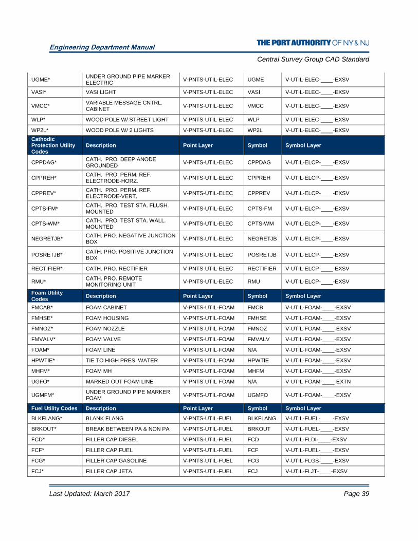
Engineering Department Manual
Central Survey Group CAD Standard
Last Updated: March 2017 Page 39
UGME* UNDER GROUND PIPE MARKER ELECTRIC
V-PNTS-UTIL-ELEC UGME V-UTIL-ELEC-____-EXSV
VASI* VASI LIGHT V-PNTS-UTIL-ELEC VASI V-UTIL-ELEC-____-EXSV
VMCC* VARIABLE MESSAGE CNTRL. CABINET
V-PNTS-UTIL-ELEC VMCC V-UTIL-ELEC-____-EXSV
WLP* WOOD POLE W/ STREET LIGHT V-PNTS-UTIL-ELEC WLP V-UTIL-ELEC-____-EXSV
WP2L* WOOD POLE W/ 2 LIGHTS V-PNTS-UTIL-ELEC WP2L V-UTIL-ELEC-____-EXSV
Cathodic Protection Utility Codes
Description Point Layer Symbol Symbol Layer
CPPDAG* CATH. PRO. DEEP ANODE GROUNDED
V-PNTS-UTIL-ELEC CPPDAG V-UTIL-ELCP-____-EXSV
CPPREH* CATH. PRO. PERM. REF. ELECTRODE-HORZ.
V-PNTS-UTIL-ELEC CPPREH V-UTIL-ELCP-____-EXSV
CPPREV* CATH. PRO. PERM. REF. ELECTRODE-VERT.
V-PNTS-UTIL-ELEC CPPREV V-UTIL-ELCP-____-EXSV
CPTS-FM* CATH. PRO. TEST STA. FLUSH. MOUNTED
V-PNTS-UTIL-ELEC CPTS-FM V-UTIL-ELCP-____-EXSV
CPTS-WM* CATH. PRO. TEST STA. WALL. MOUNTED
V-PNTS-UTIL-ELEC CPTS-WM V-UTIL-ELCP-____-EXSV
NEGRETJB* CATH. PRO. NEGATIVE JUNCTION BOX
V-PNTS-UTIL-ELEC NEGRETJB V-UTIL-ELCP-____-EXSV
POSRETJB* CATH. PRO. POSITIVE JUNCTION BOX
V-PNTS-UTIL-ELEC POSRETJB V-UTIL-ELCP-____-EXSV
RECTIFIER* CATH. PRO. RECTIFIER V-PNTS-UTIL-ELEC RECTIFIER V-UTIL-ELCP-____-EXSV
RMU* CATH. PRO. REMOTE MONITORING UNIT
V-PNTS-UTIL-ELEC RMU V-UTIL-ELCP-____-EXSV
Foam Utility Codes
Description Point Layer Symbol Symbol Layer
FMCAB* FOAM CABINET V-PNTS-UTIL-FOAM FMCB V-UTIL-FOAM-____-EXSV
FMHSE* FOAM HOUSING V-PNTS-UTIL-FOAM FMHSE V-UTIL-FOAM-____-EXSV
FMNOZ* FOAM NOZZLE V-PNTS-UTIL-FOAM FMNOZ V-UTIL-FOAM-____-EXSV
FMVALV* FOAM VALVE V-PNTS-UTIL-FOAM FMVALV V-UTIL-FOAM-____-EXSV
FOAM* FOAM LINE V-PNTS-UTIL-FOAM N/A V-UTIL-FOAM-____-EXSV
HPWTIE* TIE TO HIGH PRES. WATER V-PNTS-UTIL-FOAM HPWTIE V-UTIL-FOAM-____-EXSV
MHFM* FOAM MH V-PNTS-UTIL-FOAM MHFM V-UTIL-FOAM-____-EXSV
UGFO* MARKED OUT FOAM LINE V-PNTS-UTIL-FOAM N/A V-UTIL-FOAM-____-EXTN
UGMFM* UNDER GROUND PIPE MARKER FOAM
V-PNTS-UTIL-FOAM UGMFO V-UTIL-FOAM-____-EXSV
Fuel Utility Codes Description Point Layer Symbol Symbol Layer
BLKFLANG* BLANK FLANG V-PNTS-UTIL-FUEL BLKFLANG V-UTIL-FUEL-____-EXSV
BRKOUT* BREAK BETWEEN PA & NON PA V-PNTS-UTIL-FUEL BRKOUT V-UTIL-FUEL-____-EXSV
FCD* FILLER CAP DIESEL V-PNTS-UTIL-FUEL FCD V-UTIL-FLDI-____-EXSV
FCF* FILLER CAP FUEL V-PNTS-UTIL-FUEL FCF V-UTIL-FUEL-____-EXSV
FCG* FILLER CAP GASOLINE V-PNTS-UTIL-FUEL FCG V-UTIL-FLGS-____-EXSV
FCJ* FILLER CAP JETA V-PNTS-UTIL-FUEL FCJ V-UTIL-FLJT-____-EXSV

Engineering Department Manual
Central Survey Group CAD Standard
Last Updated: March 2017 Page 40
FCO* FILLER CAP OIL V-PNTS-UTIL-FUEL FCO V-UTIL-FUEL-OIL_-EXSV
FCP* FILLER CAP PROPANE V-PNTS-UTIL-FUEL FCP V-UTIL-FLPG-____-EXSV
FILTSTA* FUEL FILTRATION STATION V-PNTS-UTIL-FUEL FILTSTA V-UTIL-FUEL-____-EXSV
FIW* FUEL INSPECTION WELL V-PNTS-UTIL-FUEL FIW V-UTIL-FUEL-____-EXSV
FUEL* FUEL LINE V-PNTS-UTIL-FUEL N/A V-UTIL-FUEL-____-EXSV
FUI* FUEL ISOLATION V-PNTS-UTIL-FUEL FUI V-UTIL-FUEL-____-EXSV
FUP* FUEL PUMP V-PNTS-UTIL-FUEL FUP V-UTIL-FUEL-____-EXSV
FUPT* FUEL LISTENING POST V-PNTS-UTIL-FUEL FUELPOST V-UTIL-FUEL-____-EXSV
FUTK* FUEL TANK V-PNTS-UTIL-FUEL FUELTANK V-UTIL-FUEL-____-EXSV
FUVT* FUEL VENT V-PNTS-UTIL-FUEL FUVT V-UTIL-FUEL-____-EXSV
FV* FUEL VALVE V-PNTS-UTIL-FUEL FV V-UTIL-FUEL-____-EXSV
FVP* FUEL VALVEPIT V-PNTS-UTIL-FUEL FVP V-UTIL-FUEL-____-EXSV
GLV* GASOLINE VALVE V-PNTS-UTIL-FUEL GLV V-UTIL-FLGL-____-EXSV
HYDPIT* FUEL HYDRANT PIT V-PNTS-UTIL-FUEL HYDPIT V-UTIL-FUEL-____-EXSV
LRAKBOT* LOADING RACK BOTTOM V-PNTS-UTIL-FUEL LRAKBOT V-UTIL-FUEL-____-EXSV
LRAKTOP* LOADING RACK TOP V-PNTS-UTIL-FUEL LRAKTOP V-UTIL-FUEL-____-EXSV
MHFL* FUEL MH V-PNTS-UTIL-FUEL MHFL V-UTIL-FUEL-____-EXSV
PIG* PIG ACCESS V-PNTS-UTIL-FUEL PIG V-UTIL-FUEL-____-EXSV
PSTAF* PUMP STATION FUEL V-PNTS-UTIL-FUEL PMPSTAF V-UTIL-FUEL-____-EXSV
TESTSTA* TEST STATION FUEL V-PNTS-UTIL-FUEL TESTSTA V-UTIL-FUEL-____-EXSV
UGFL* MARKED OUT FUEL LINE V-PNTS-UTIL-FUEL N/A V-UTIL-FUEL-____-EXTN
UGMFL* UNDER GROUND PIPE MARKER FUEL
V-PNTS-UTIL-FUEL UGMFL V-UTIL-FUEL-____-EXSV
VNTP* VENT PIT V-PNTS-UTIL-FUEL VNTP V-UTIL-FUEL-____-EXSV
Natural Gas Utility Codes
Description Point Layer Symbol Symbol Layer
BXG* NATURAL GAS BOX V-PNTS-UTIL-NGAS BXG V-UTIL-NGAS-____-EXSV
CMST* COMPRESSOR STATION V-PNTS-UTIL-NGAS CMST V-UTIL-NGAS-____-EXSV
CROSSG* FOUR WAY NATURAL GAS TEE V-PNTS-UTIL-NGAS CROSS V-UTIL-NGAS-____-EXSV
GAS* NATURAL GAS LINE V-PNTS-UTIL-NGAS N/A V-UTIL-NGAS-____-EXUV
GM* NATURAL GAS METER V-PNTS-UTIL-NGAS GM V-UTIL-NGAS-____-EXSV
GRSR* GAS RISER V-PNTS-UTIL-NGAS GRSR V-UTIL-NGAS-____-EXSV
GT* NATURAL GAS TEST V-PNTS-UTIL-NGAS GT V-UTIL-NGAS-____-EXSV
GV* NATURAL GAS VALVE V-PNTS-UTIL-NGAS GV V-UTIL-NGAS-____-EXSV
MHG* NATURAL GAS MH V-PNTS-UTIL-NGAS MHG V-UTIL-NGAS-____-EXSV
TEEG* NATURAL GAS TEE V-PNTS-UTIL-NGAS TEE V-UTIL-NGAS-____-EXSV
UGG* MARKED OUT NATURAL GAS LINE
V-PNTS-UTIL-NGAS N/A V-UTIL-NGAS-____-EXTN
UGMG* UNDER GROUND PIPE MARKER NATURAL GAS
V-PNTS-UTIL-NGAS UGMG V-UTIL-NGAS-____-EXSV

Engineering Department Manual
Central Survey Group CAD Standard
Last Updated: March 2017 Page 41
Sanitary Utility Codes
Description Point Layer Symbol Symbol Layer
CO* CLEANOUT SANITARY V-PNTS-UTIL-SSWR CO V-UTIL-SANT-____-EXSV
MHS* SANITARY SEWER MH V-PNTS-UTIL-SSWR MHS V-UTIL-SANT-____-EXSV
OWSS* OIL WATER SEPERATOR SANITARY
V-PNTS-UTIL-SSWR OWSS V-UTIL-SANT-____-EXSV
PSTAS* PUMP STATION SANITARY V-PNTS-UTIL-SSWR PMPSTAS V-UTIL-SANT-____-EXSV
SAN* SANITARY SEWER LINE V-PNTS-UTIL-SSWR N/A V-UTIL-SANT-____-EXSV
STANK* SLUDGE TANK V-PNTS-UTIL-SSWR STANK V-UTIL-SANT-____-EXSV
SVG* SANITARY VALVE V-PNTS-UTIL-SSWR SV V-UTIL-SANT-____-EXSV
UGSA* MARKED OUT SANITARY SEWER LINE
V-PNTS-UTIL-SSWR N/A V-UTIL-SANT-____-EXTN
Steam Utility Codes
Description Point Layer Symbol Symbol Layer
CROSSST* FOUR WAY STEAM TEE V-PNTS-UTIL-STEM CROSS V-UTIL-STEM-____-EXSV
MHST* STEAM MH V-PNTS-UTIL-STEM MHST V-UTIL-STEM-____-EXSV
MHSTB* STEAM MH BURIED V-PNTS-UTIL-STEM MHSTB V-UTIL-STEM-____-EXTN
STEAM* STEAM LINE V-PNTS-UTIL-STEM N/A V-UTIL-STEM-____-EXSV
STEAMA* STEAM ANCHOR BLOCK V-PNTS-UTIL-STEM STEAMA V-UTIL-STEM-____-EXSV
STEAMCC* STEAM COOLING CHAMBER V-PNTS-UTIL-STEM STEAMCC V-UTIL-STEM-____-EXSV
STEAMEJ* STEAM EXPANSION JOINT V-PNTS-UTIL-STEM STEAMEJ V-UTIL-STEM-____-EXSV
STEAMMG* STEAM MOON GUIDE V-PNTS-UTIL-STEM STEAMMG V-UTIL-STEM-____-EXSV
STEAMSJ* STEAM SLIP JOINT V-PNTS-UTIL-STEM STEAMSJ V-UTIL-STEM-____-EXSV
STEAMV* STEAM VALVE V-PNTS-UTIL-STEM STEAMV V-UTIL-STEM-____-EXSV
TEEST* TEE STEAM V-PNTS-UTIL-STEM TEE V-UTIL-STEM-____-EXSV
UGMST* UNDER GROUND PIPE MARKER STEAM
V-PNTS-UTIL-STEM UGMST V-UTIL-STEM-____-EXSV
UGST* MARKED OUT STEAM LINE V-PNTS-UTIL-STEM N/A V-UTIL-STEM-____-EXTN
TDS Utility Codes Description Point Layer Symbol Symbol Layer
BXTDS* THERMAL DISTRIBUTION SYSTEM BOX
V-PNTS-UTIL-TDSL BXTDS V-UTIL-TDSL-____-EXSV
MHTW* TDS WATER MH V-PNTS-UTIL-TDSL MHTW V-UTIL-TDSL-____-EXSV
TDS* TDS WATER LINE V-PNTS-UTIL-TDSL N/A V-UTIL-TDSL-____-EXUV
TDSV* TDS VALVE W/ STRUCTURE V-PNTS-UTIL-TDSL TDSV V-UTIL-TDSL-____-EXSV
TDSVA* TDS VALVE W/ ACTIVATOR V-PNTS-UTIL-TDSL TDSVA V-UTIL-TDSL-____-EXSV
TDSVNS* TDS VALVE W/OUT STRUCTURE V-PNTS-UTIL-TDSL TDSVNS V-UTIL-TDSL-____-EXSV
UGMTD* UNDER GROUND PIPE MARKER TDS
V-PNTS-UTIL-TDSL UGMTD V-UTIL-TDSL-____-EXSV
UGTD* MARKED OUT TDS LINE V-PNTS-UTIL-TDSL N/A V-UTIL-TDSL-____-EXTN
VPTM* TDS VALVE PIT MANHOLE V-PNTS-UTIL-TDSL VPTM V-UTIL-TDSL-____-EXSV
Unknown Utility Codes
Description Point Layer Symbol Symbol Layer
BXU* UNKKOWN BOX V-PNTS-UTIL-UKWN BXU V-UTIL-UKWN-____-EXSV
CROSS* FOUR WAY TEE V-PNTS-UTIL-UKWN CROSS V-UTIL-UKWN-____-EXSV
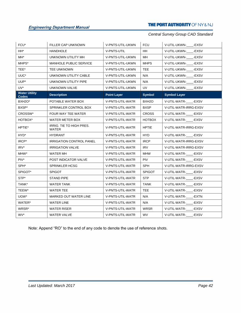
Engineering Department Manual
Central Survey Group CAD Standard
Last Updated: March 2017 Page 42
FCU* FILLER CAP UNKNOWN V-PNTS-UTIL-UKWN FCU V-UTIL-UKWN-____-EXSV
HH* HANDHOLE V-PNTS-UTIL HH V-UTIL-UKWN-____-EXSV
MH* UNKNOWN UTILITY MH V-PNTS-UTIL-UKWN MH V-UTIL-UKWN-____-EXSV
MHPS* MANHOLE PUBLIC SERVICE V-PNTS-UTIL-UKWN MHPS V-UTIL-UKWN-____-EXSV
TEE* TEE UNKNOWN V-PNTS-UTIL-UKWN TEE V-UTIL-UKWN-____-EXSV
UUC* UNKNOWN UTILITY CABLE V-PNTS-UTIL-UKWN N/A V-UTIL-UKWN-____-EXSV
UUP* UNKNOWN UTILITY PIPE V-PNTS-UTIL-UKWN N/A V-UTIL-UKWN-____-EXSV
UV* UNKNOWN VALVE V-PNTS-UTIL-UKWN UV V-UTIL-UKWN-____-EXSV
Water Utility Codes
Description Point Layer Symbol Symbol Layer
BXH2O* POTABLE WATER BOX V-PNTS-UTIL-WATR BXH2O V-UTIL-WATR-____-EXSV
BXSP* SPRINKLER CONTROL BOX V-PNTS-UTIL-WATR BXSP V-UTIL-WATR-IRRG-EXSV
CROSSW* FOUR WAY TEE WATER V-PNTS-UTIL-WATR CROSS V-UTIL-WATR-____-EXSV
HOTBOX* WATER METER BOX V-PNTS-UTIL-WATR HOTBOX V-UTIL-WATR-____-EXSV
HPTIE* IRRIG. TIE TO HIGH PRES. WATER
V-PNTS-UTIL-WATR HPTIE V-UTIL-WATR-IRRG-EXSV
HYD* HYDRANT V-PNTS-UTIL-WATR HYD V-UTIL-WATR-____-EXSV
IRCP* IRRIGATION CONTROL PANEL V-PNTS-UTIL-WATR IRCP V-UTIL-WATR-IRRG-EXSV
IRV* IRRIGATION VALVE V-PNTS-UTIL-WATR IRV V-UTIL-WATR-IRRG-EXSV
MHW* WATER MH V-PNTS-UTIL-WATR MHW V-UTIL-WATR-____-EXSV
PIV* POST INDICATOR VALVE V-PNTS-UTIL-WATR PIV V-UTIL-WATR-____-EXSV
SPH* SPRINKLER HCSG V-PNTS-UTIL-WATR SPH V-UTIL-WATR-IRRG-EXSV
SPIGOT* SPIGOT V-PNTS-UTIL-WATR SPIGOT V-UTIL-WATR-____-EXSV
STP* STAND PIPE V-PNTS-UTIL-WATR STP V-UTIL-WATR-____-EXSV
TANK* WATER TANK V-PNTS-UTIL-WATR TANK V-UTIL-WATR-____-EXSV
TEEW* WATER TEE V-PNTS-UTIL-WATR TEE V-UTIL-WATR-____-EXSV
UGW* MARKED OUT WATER LINE V-PNTS-UTIL-WATR N/A V-UTIL-WATR-____-EXTN
WATER* WATER LINE V-PNTS-UTIL-WATR N/A V-UTIL-WATR-____-EXSV
WRSR* WATER RISER V-PNTS-UTIL-WATR WRSR V-UTIL-WATR-____-EXSV
WV* WATER VALVE V-PNTS-UTIL-WATR WV V-UTIL-WATR-____-EXSV
Note: Append “RO” to the end of any code to denote the use of reference shots.
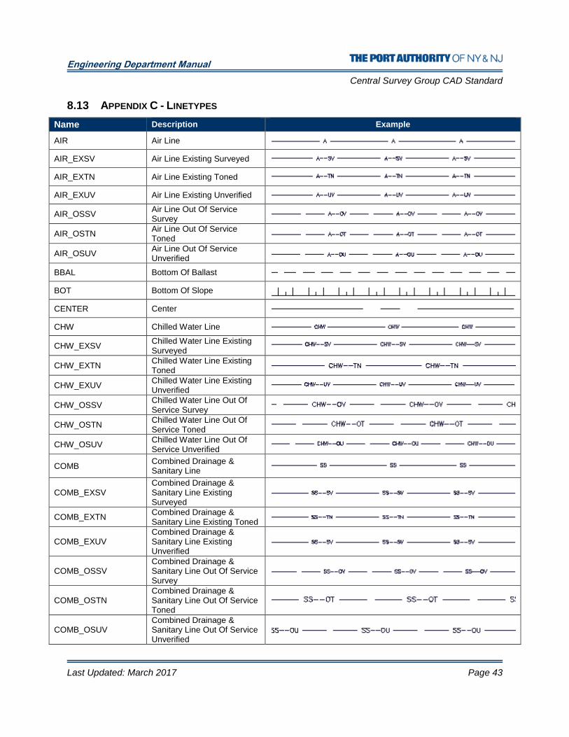
Engineering Department Manual
Central Survey Group CAD Standard
Last Updated: March 2017 Page 43
8.13 APPENDIX C - LINETYPES
Name Description Example
AIR Air Line
AIR_EXSV Air Line Existing Surveyed
AIR_EXTN Air Line Existing Toned
AIR_EXUV Air Line Existing Unverified
AIR_OSSV Air Line Out Of Service Survey
AIR_OSTN Air Line Out Of Service Toned
AIR_OSUV Air Line Out Of Service Unverified
BBAL Bottom Of Ballast
BOT Bottom Of Slope
CENTER Center
CHW Chilled Water Line
CHW_EXSV Chilled Water Line Existing Surveyed
CHW_EXTN Chilled Water Line Existing Toned
CHW_EXUV Chilled Water Line Existing Unverified
CHW_OSSV Chilled Water Line Out Of Service Survey
CHW_OSTN Chilled Water Line Out Of Service Toned
CHW_OSUV Chilled Water Line Out Of Service Unverified
COMB Combined Drainage & Sanitary Line
COMB_EXSV Combined Drainage & Sanitary Line Existing Surveyed
COMB_EXTN Combined Drainage & Sanitary Line Existing Toned
COMB_EXUV Combined Drainage & Sanitary Line Existing Unverified
COMB_OSSV Combined Drainage & Sanitary Line Out Of Service Survey
COMB_OSTN Combined Drainage & Sanitary Line Out Of Service Toned
COMB_OSUV Combined Drainage & Sanitary Line Out Of Service Unverified

Engineering Department Manual
Central Survey Group CAD Standard
Last Updated: March 2017 Page 44
Name Description Example
COMM Communications Line
COMM_EXSV Communications Line Existing Surveyed
COMM_EXTN Communications Line Existing Toned
COMM_EXUV Communications Line Existing Unverified
COMM_FAA FAA Communications Line
COMM_FAA_EXSV FAA Communications Line Existing Surveyed
COMM_FAA_EXTN FAA Communications Line Existing Toned
COMM_FAA_EXUV FAA Communications Line Existing Unverified
COMM_FAA_OSSV FAA Communications Line Out Of Service Survey
COMM_FAA_OSTN FAA Communications Line Out Of Service Toned
COMM_FAA_OSUV FAA Communications Line Out Of Service Unverified
COMM_FIRE Fire Communication Line
COMM_FIRE_EXSV Fire Communication Line Existing Surveyed
COMM_FIRE_EXTN Fire Communication Line Existing Toned
COMM_FIRE_EXUV Fire Communication Line Existing Unverified
COMM_FIRE_OSSV Fire Communication Line Out Of Service Survey
COMM_FIRE_OSTN Fire Communication Line Out Of Service Toned
COMM_FIRE_OSUV Fire Communication Line Out Of Service Unverified
COMM_OSSV Communications Line Out Of Service Survey
COMM_OSTN Communications Line Out Of Service Toned
COMM_OSUV Communications Line Out Of Service Unverified
COMM_SEC Security Communication Line
COMM_SEC_EXSV Security Communication Line Existing Surveyed
COMM_SEC_EXTN Security Communication Line Existing Toned
COMM_SEC_EXUV Security Communication Line Existing Unverified
COMM_SEC_OSSV Security Communication Line Out Of Service Survey
COMM_SEC_OSTN Security Communication Line Out Of Service Toned
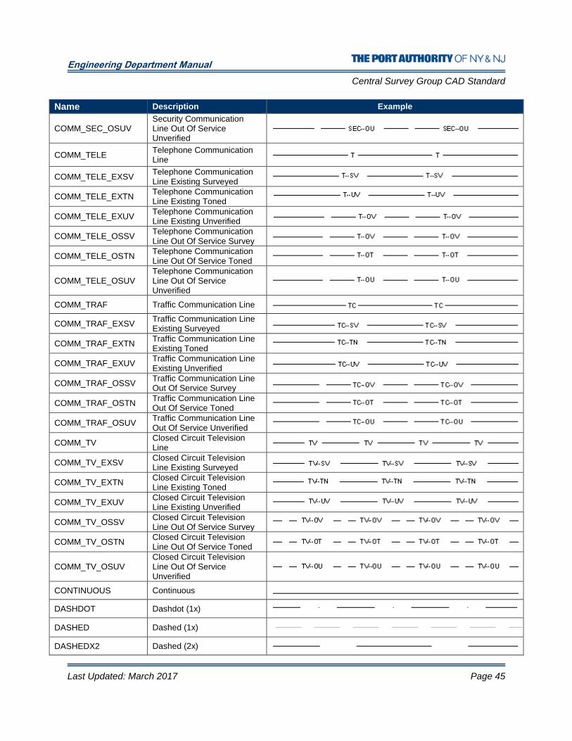
Engineering Department Manual
Central Survey Group CAD Standard
Last Updated: March 2017 Page 45
Name Description Example
COMM_SEC_OSUV Security Communication Line Out Of Service Unverified
COMM_TELE Telephone Communication Line
COMM_TELE_EXSV Telephone Communication Line Existing Surveyed
COMM_TELE_EXTN Telephone Communication Line Existing Toned
COMM_TELE_EXUV Telephone Communication Line Existing Unverified
COMM_TELE_OSSV Telephone Communication Line Out Of Service Survey
COMM_TELE_OSTN Telephone Communication Line Out Of Service Toned
COMM_TELE_OSUV Telephone Communication Line Out Of Service Unverified
COMM_TRAF Traffic Communication Line
COMM_TRAF_EXSV Traffic Communication Line Existing Surveyed
COMM_TRAF_EXTN Traffic Communication Line Existing Toned
COMM_TRAF_EXUV Traffic Communication Line Existing Unverified
COMM_TRAF_OSSV Traffic Communication Line Out Of Service Survey
COMM_TRAF_OSTN Traffic Communication Line Out Of Service Toned
COMM_TRAF_OSUV Traffic Communication Line Out Of Service Unverified
COMM_TV Closed Circuit Television Line
COMM_TV_EXSV Closed Circuit Television Line Existing Surveyed
COMM_TV_EXTN Closed Circuit Television Line Existing Toned
COMM_TV_EXUV Closed Circuit Television Line Existing Unverified
COMM_TV_OSSV Closed Circuit Television Line Out Of Service Survey
COMM_TV_OSTN Closed Circuit Television Line Out Of Service Toned
COMM_TV_OSUV Closed Circuit Television Line Out Of Service Unverified
CONTINUOUS Continuous
DASHDOT Dashdot (1x)
DASHED Dashed (1x)
DASHEDX2 Dashed (2x)

Engineering Department Manual
Central Survey Group CAD Standard
Last Updated: March 2017 Page 46
Name Description Example
DIVIDE Divide (1x)
DOT2 Dot (0.5x)
DRAIN Drainage Line
DRAIN_EXSV Drainage Line Existing Surveyed
DRAIN_EXTN Drainage Line Existing Toned
DRAIN_EXUV Drainage Line Existing Unverified
DRAIN_OSSV Drainage Line Out Of Service Survey
DRAIN_OSTN Drainage Line Out Of Service Toned
DRAIN_OSUV Drainage Line Out Of Service Unverified
DSL DSL Line
DSL_EXSV DSL Existing Surveyed
DSL_EXTN DSL Existing Toned
DSL_EXUV DSL Existing Unverified
DSL_OSSV DSL Out Of Service Survey
DSL_OSTN DSL Out Of Service Toned
DSL_OSUV DSL Out Of Service Unverified
ELEC Electric Line
ELEC_5KV 5kv Electric Line
ELEC-5KV_EXSV 5kv Electric Line Existing Surveyed
ELEC_5KV_EXTN 5kv Electric Line Existing Toned
ELEC_5KV_EXUV 5kv Electric Line Existing Unverified
ELEC_5KV_OSSV 5kv Electric Line Out Of Service Survey
ELEC_5KV_OSTN 5kv Electric Line Out Of Service Toned
ELEC_5KV_OSUV 5kv Electric Line Out Of Service Unverified
ELEC_13_8KV 13.8kv Electric Line
ELEC_13_8KV_EXSV 13.8kv Electric Line Existing Surveyed
ELEC_13_8KV_EXTN 13.8kv Electric Line Existing Toned
ELEC_13_8KV_EXUV 13.8kv Electric Line Existing Unverified
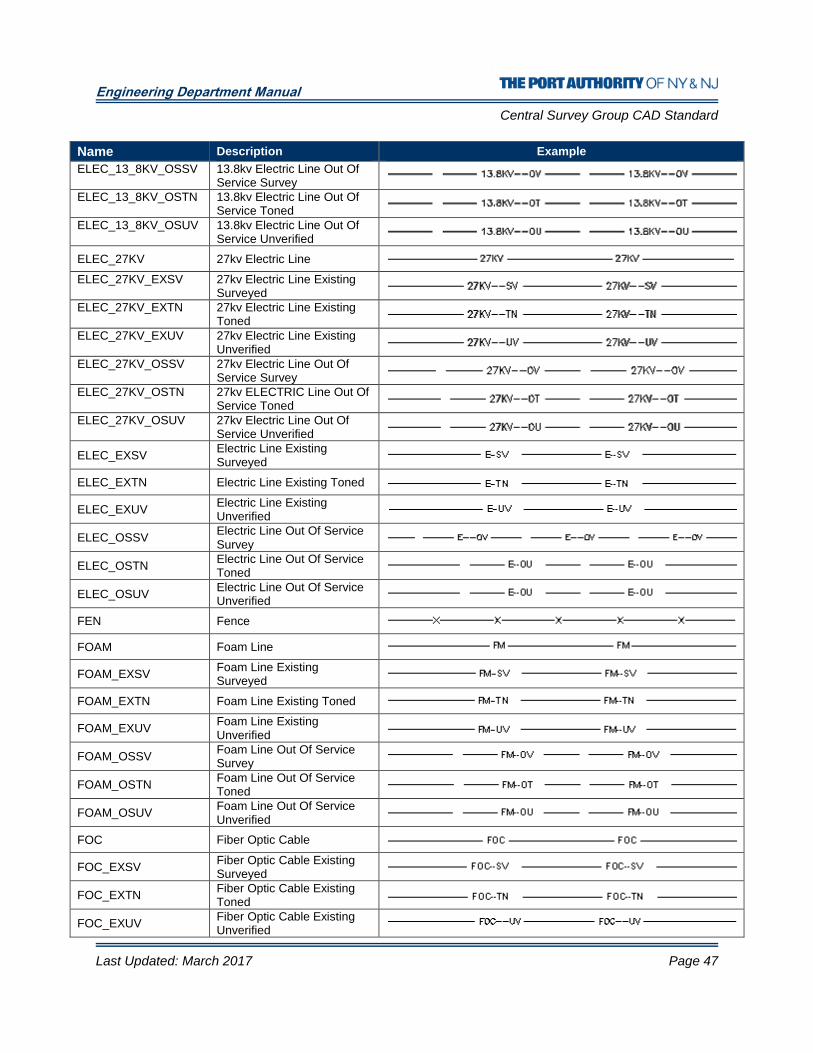
Engineering Department Manual
Central Survey Group CAD Standard
Last Updated: March 2017 Page 47
Name Description Example
ELEC_13_8KV_OSSV 13.8kv Electric Line Out Of Service Survey
ELEC_13_8KV_OSTN 13.8kv Electric Line Out Of Service Toned
ELEC_13_8KV_OSUV 13.8kv Electric Line Out Of Service Unverified
ELEC_27KV 27kv Electric Line
ELEC_27KV_EXSV 27kv Electric Line Existing Surveyed
ELEC_27KV_EXTN 27kv Electric Line Existing Toned
ELEC_27KV_EXUV 27kv Electric Line Existing Unverified
ELEC_27KV_OSSV 27kv Electric Line Out Of Service Survey
ELEC_27KV_OSTN 27kv ELECTRIC Line Out Of Service Toned
ELEC_27KV_OSUV 27kv Electric Line Out Of Service Unverified
ELEC_EXSV Electric Line Existing Surveyed
ELEC_EXTN Electric Line Existing Toned
ELEC_EXUV Electric Line Existing Unverified
ELEC_OSSV Electric Line Out Of Service Survey
ELEC_OSTN Electric Line Out Of Service Toned
ELEC_OSUV Electric Line Out Of Service Unverified
FEN Fence
FOAM Foam Line
FOAM_EXSV Foam Line Existing Surveyed
FOAM_EXTN Foam Line Existing Toned
FOAM_EXUV Foam Line Existing Unverified
FOAM_OSSV Foam Line Out Of Service Survey
FOAM_OSTN Foam Line Out Of Service Toned
FOAM_OSUV Foam Line Out Of Service Unverified
FOC Fiber Optic Cable
FOC_EXSV Fiber Optic Cable Existing Surveyed
FOC_EXTN Fiber Optic Cable Existing Toned
FOC_EXUV Fiber Optic Cable Existing Unverified
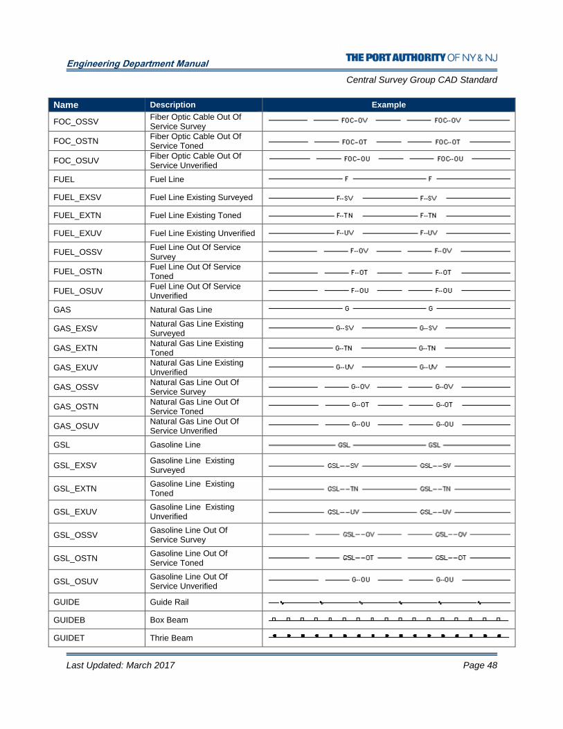
Engineering Department Manual
Central Survey Group CAD Standard
Last Updated: March 2017 Page 48
Name Description Example
FOC_OSSV Fiber Optic Cable Out Of Service Survey
FOC_OSTN Fiber Optic Cable Out Of Service Toned
FOC_OSUV Fiber Optic Cable Out Of Service Unverified
FUEL Fuel Line
FUEL_EXSV Fuel Line Existing Surveyed
FUEL_EXTN Fuel Line Existing Toned
FUEL_EXUV Fuel Line Existing Unverified
FUEL_OSSV Fuel Line Out Of Service Survey
FUEL_OSTN Fuel Line Out Of Service Toned
FUEL_OSUV Fuel Line Out Of Service Unverified
GAS Natural Gas Line
GAS_EXSV Natural Gas Line Existing Surveyed
GAS_EXTN Natural Gas Line Existing Toned
GAS_EXUV Natural Gas Line Existing Unverified
GAS_OSSV Natural Gas Line Out Of Service Survey
GAS_OSTN Natural Gas Line Out Of Service Toned
GAS_OSUV Natural Gas Line Out Of Service Unverified
GSL Gasoline Line
GSL_EXSV Gasoline Line Existing Surveyed
GSL_EXTN Gasoline Line Existing Toned
GSL_EXUV Gasoline Line Existing Unverified
GSL_OSSV Gasoline Line Out Of Service Survey
GSL_OSTN Gasoline Line Out Of Service Toned
GSL_OSUV Gasoline Line Out Of Service Unverified
GUIDE Guide Rail
GUIDEB Box Beam
GUIDET Thrie Beam

Engineering Department Manual
Central Survey Group CAD Standard
Last Updated: March 2017 Page 49
Name Description Example
GUIDEW W Beam
HANDRAIL Handrail
HEDGE Hedge
HIDDEN Hidden (1x)
HIDDENX2 Hidden (2x)
HPW High Pressure Water Line (1x)
HPW High Pressure Water Line
HPW_EXSV High Pressure Water Line Existing Surveyed
HPW_EXTN High Pressure Water Line Existing Toned
HPW_EXUV High Pressure Water Line Existing Unverified
HPW_OSSV High Pressure Water Line Out Of Service Survey
HPW_OSTN High Pressure Water Line Out Of Service Toned
HPW_OSUV High Pressure Water Line Out Of Service Unverified
JET Jet Fuel Line
JET_EXSV Jet Fuel Line Existing Surveyed
JET_EXTN Jet Fuel Line Existing Toned
JET_EXUV Jet Fuel Line Existing Unverified
JET_OSSV Jet Fuel Line Out Of Service Survey
JET_OSTN Jet Fuel Line Out Of Service Toned
JET_OSUV Jet Fuel Line Out Of Service Unverified
MPW Medium Pressure Water Line
MPW_EXSV Medium Pressure Water Line Existing Surveyed
MPW_EXTN Medium Pressure Water Line Existing Toned
MPW_EXUV Medium Pressure Water Line Existing Unverified
MPW_OSSV Medium Pressure Water Line Out Of Service Survey
MPW_OSTN Medium Pressure Water Line Out Of Service Toned
MPW_OSUV Medium Pressure Water Line Out Of Service Unverified

Engineering Department Manual
Central Survey Group CAD Standard
Last Updated: March 2017 Page 50
Name Description Example
PHANTOM Phantom (1x)
PHANTOM2 Phantom (0.5x)
POWER Power Line
PPG Propane Gas Line
PPG_EXSV Propane Gas Line Existing Surveyed
PPG_EXTN Propane Gas Line Existing Toned
PPG_EXUV Propane Gas Line Existing Unverified
PPG_OSSV Propane Gas Line Out Of Service Survey
PPG_OSTN Propane Gas Line Out Of Service Toned
PPG_OSUV Propane Gas Line Out Of Service Unverified
ROCK Rock Outcrop
RR Railroad
SAN Sanitary Sewer Line (1x)
SAN_EXSV Sanitary Sewer Existing Surveyed
SAN_EXTN Sanitary Sewer Existing Toned
SAN_EXUV Sanitary Sewer Existing Unverified
SAN_OSSV Sanitary Sewer Out Of Service Survey
SAN_OSTN Sanitary Sewer Out Of Service Toned
SAN_OSUV Sanitary Sewer Out Of Service Unverified
STEAM Steam Line
STEAM_EXSV Steam Line Existing Surveyed
STEAM_EXTN Steam Line Existing Toned
STEAM_EXUV Steam Line Existing Unverified
STEAM_OSSV Steam Line Out Of Service Survey
STEAM_OSTN Steam Line Out Of Service Toned
STEAM_OSUV Steam Line Out Of Service Unverified
STREAM Stream Line
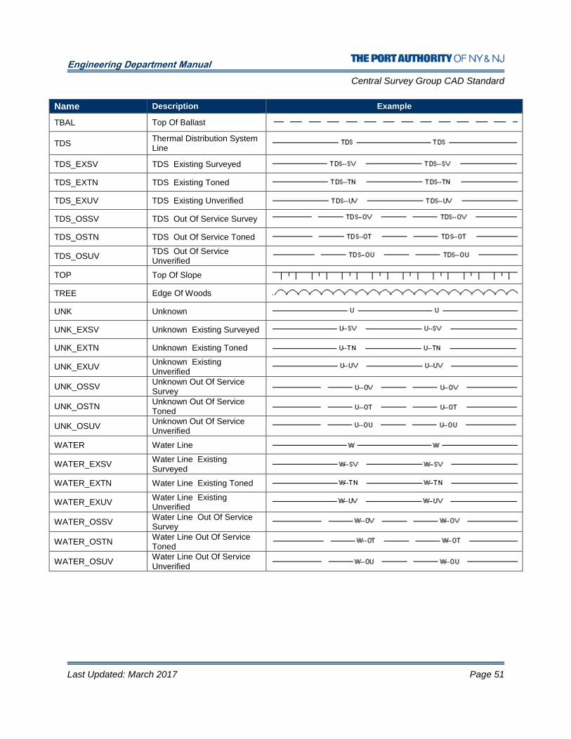
Engineering Department Manual
Central Survey Group CAD Standard
Last Updated: March 2017 Page 51
Name Description Example
TBAL Top Of Ballast
TDS Thermal Distribution System Line
TDS_EXSV TDS Existing Surveyed
TDS_EXTN TDS Existing Toned
TDS_EXUV TDS Existing Unverified
TDS_OSSV TDS Out Of Service Survey
TDS_OSTN TDS Out Of Service Toned
TDS_OSUV TDS Out Of Service Unverified
TOP Top Of Slope
TREE Edge Of Woods
UNK Unknown
UNK_EXSV Unknown Existing Surveyed
UNK_EXTN Unknown Existing Toned
UNK_EXUV Unknown Existing Unverified
UNK_OSSV Unknown Out Of Service Survey
UNK_OSTN Unknown Out Of Service Toned
UNK_OSUV Unknown Out Of Service Unverified
WATER Water Line
WATER_EXSV Water Line Existing Surveyed
WATER_EXTN Water Line Existing Toned
WATER_EXUV Water Line Existing Unverified
WATER_OSSV Water Line Out Of Service Survey
WATER_OSTN Water Line Out Of Service Toned
WATER_OSUV Water Line Out Of Service Unverified
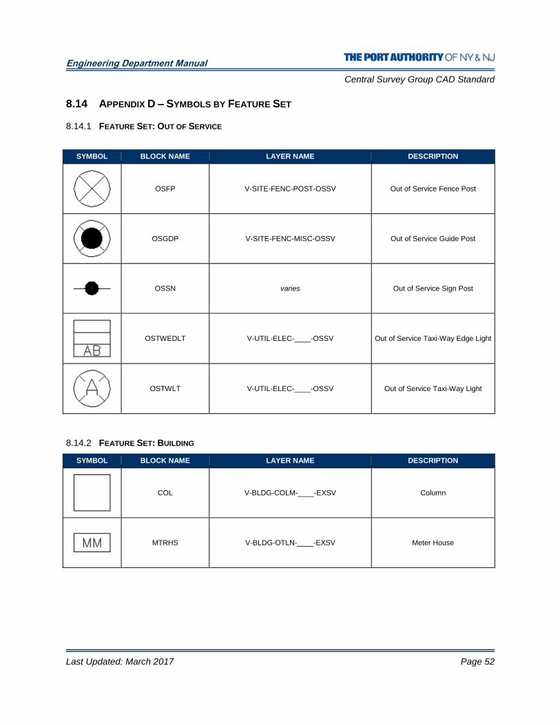
Engineering Department Manual
Central Survey Group CAD Standard
Last Updated: March 2017 Page 52
8.14 APPENDIX D – SYMBOLS BY FEATURE SET
8.14.1 FEATURE SET: OUT OF SERVICE
SYMBOL BLOCK NAME LAYER NAME DESCRIPTION
OSFP V-SITE-FENC-POST-OSSV Out of Service Fence Post
OSGDP V-SITE-FENC-MISC-OSSV Out of Service Guide Post
OSSN varies Out of Service Sign Post
OSTWEDLT V-UTIL-ELEC-____-OSSV Out of Service Taxi-Way Edge Light
OSTWLT V-UTIL-ELEC-____-OSSV Out of Service Taxi-Way Light
8.14.2 FEATURE SET: BUILDING
SYMBOL BLOCK NAME LAYER NAME DESCRIPTION
COL V-BLDG-COLM-____-EXSV Column
MTRHS V-BLDG-OTLN-____-EXSV Meter House
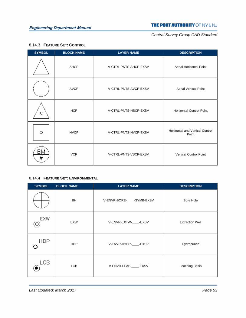
Engineering Department Manual
Central Survey Group CAD Standard
Last Updated: March 2017 Page 53
8.14.3 FEATURE SET: CONTROL
SYMBOL BLOCK NAME LAYER NAME DESCRIPTION
AHCP V-CTRL-PNTS-AHCP-EXSV Aerial Horizontal Point
AVCP V-CTRL-PNTS-AVCP-EXSV Aerial Vertical Point
HCP V-CTRL-PNTS-HSCP-EXSV Horizontal Control Point
HVCP V-CTRL-PNTS-HVCP-EXSV Horizontal and Vertical Control
Point
VCP V-CTRL-PNTS-VSCP-EXSV Vertical Control Point
8.14.4 FEATURE SET: ENVIRONMENTAL
SYMBOL BLOCK NAME LAYER NAME DESCRIPTION
BH V-ENVR-BORE-____-SYMB-EXSV Bore Hole
EXW V-ENVR-EXTW-____-EXSV Extraction Well
HDP V-ENVR-HYDP-____-EXSV Hydropunch
LCB V-ENVR-LEAB-____-EXSV Leaching Basin

Engineering Department Manual
Central Survey Group CAD Standard
Last Updated: March 2017 Page 54
MW V-ENVR-MONW-____-EXSV Monitoring Well
SPT V-ENVR-SETP-____-EXSV Settling Point
WFL V-ENVR-WETL-____-EXSV Wetland Flag
8.14.5 FEATURE SET: GENERAL
SYMBOL BLOCK NAME LAYER NAME DESCRIPTION
N_ARROW V-GNRL-NOTE-SYMB-EXSV North Arrow and Bar Scale
NODE (varies) Node
NO_END (varies) No End
POINT (varies) Point
REVISION V-GNRL-NOTE-____-EXSV Revision

Engineering Department Manual
Central Survey Group CAD Standard
Last Updated: March 2017 Page 55
8.14.6 FEATURE SET: HYPSOGRAPHY
SYMBOL BLOCK NAME LAYER NAME DESCRIPTION
DTM V-HYPS-DTMP-____-EXSV Digital Terrain Model
SSHT V-HYPS-SPOT-____-EXSV Spot Shot
8.14.7 FEATURE SET: PAVEMENT MARKINGS
SYMBOL BLOCK NAME LAYER NAME DESCRIPTION
HANDI V-MARK-HNDI-____-EXSV Handicap Symbol Park
TD-6009L V-MARK-ARWS-____-EXSV 90D Left Park
TD-6009R V-MARK-ARWS-____-EXSV 90D Right Park
TD-6010L V-MARK-ARWS-____-EXSV Two Arrows Left Park
TD-6010R V-MARK-ARWS-____-EXSV Two Arrows Right Park
TD-6011L V-MARK-ARWS-____-EXSV 30D Arrow Left Parking
TD-6011R V-MARK-ARWS-____-EXSV 30D Arrow Right Parking

Engineering Department Manual
Central Survey Group CAD Standard
Last Updated: March 2017 Page 56
TD-6012 V-MARK-ARWS-____-EXSV Arrows Straight and Right Park
TD-6013 V-MARK-ARWS-____-EXSV Single Arrow Parking
TD-6014 V-MARK-ARWS-____-EXSV Divided Arrows Parking
TD-6015 V-MARK-ARWS-____-EXSV Text on Parking “STOP”
TD-6016 V-MARK-ARWS-____-EXSV Text on Parking “ONLY”
TD-6017 V-MARK-ARWS-____-EXSV Arrows Straight and Left Park
8.14.8 FEATURE SET: PAVEMENT, ROAD, AND PARKING
SYMBOL BLOCK NAME LAYER NAME DESCRIPTION
CBUMP V-PAVE-CBAR-____-EXSV Concrete Bumper
DEL V-PAVE-DLIN-SYMB-EXSV DeLineator
HR V-PAVE-HAND-SYMB-EXSV Handicap Ramp
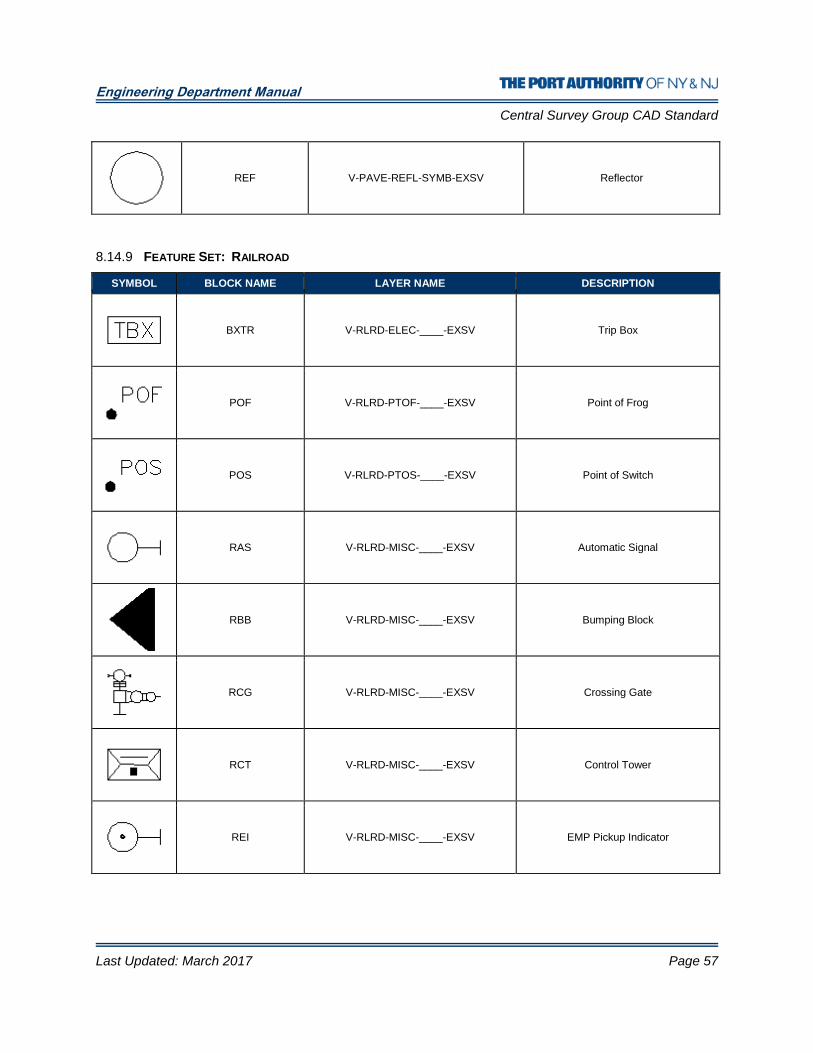
Engineering Department Manual
Central Survey Group CAD Standard
Last Updated: March 2017 Page 57
REF V-PAVE-REFL-SYMB-EXSV Reflector
8.14.9 FEATURE SET: RAILROAD
SYMBOL BLOCK NAME LAYER NAME DESCRIPTION
BXTR V-RLRD-ELEC-____-EXSV Trip Box
POF V-RLRD-PTOF-____-EXSV Point of Frog
POS V-RLRD-PTOS-____-EXSV Point of Switch
RAS V-RLRD-MISC-____-EXSV Automatic Signal
RBB V-RLRD-MISC-____-EXSV Bumping Block
RCG V-RLRD-MISC-____-EXSV Crossing Gate
RCT V-RLRD-MISC-____-EXSV Control Tower
REI V-RLRD-MISC-____-EXSV EMP Pickup Indicator

Engineering Department Manual
Central Survey Group CAD Standard
Last Updated: March 2017 Page 58
REP V-RLRD-MISC-____-EXSV REM Pickup Plat
RIMP V-RLRD-MISC-____-EXSV Impedance Bond
RIS V-RLRD-MISC-____-EXSV Interlocking Signal
RPS V-RLRD-MISC-____-EXSV Stop Power Rail
RQR V-RLRD-MISC-____-EXSV Route Request
RSB V-RLRD-MISC-____-EXSV Smashboard
RTI V-RLRD-MISC-____-EXSV Track Indicator
SB V-RLRD-MISC-____-EXSV Switch Box
8.14.10 FEATURE SET: SIGN
SYMBOL BLOCK NAME LAYER NAME DESCRIPTION
RWSN V-SIGN-RUNW-SYMB-EXSV Sign Runway

Engineering Department Manual
Central Survey Group CAD Standard
Last Updated: March 2017 Page 59
SN V-SIGN-GNRL-SYMB-EXSV Sign General
SNP V-SIGN-GNRL-____-EXSV Sign Post
VMS V-SIGN-VMSS-SYMB-EXSV Sign VMS
8.14.11 FEATURE SET: SITE FEATURES
SYMBOL BLOCK NAME LAYER NAME DESCRIPTION
ANT V-SITE-MISC-PERM-EXSV Antenna
BNCH V-SITE-MISC-PERM-EXSV Park Bench
BOL V-SITE-MISC-PERM-EXSV Bollard
BRLS V-SITE-BARL-SYMB-EXSV Sand-Filled
BUC V-SITE-VEGE-TREE-EXSV Coniferous Bush
BUD V-SITE-VEGE-TREE-EXSV Deciduous Bush
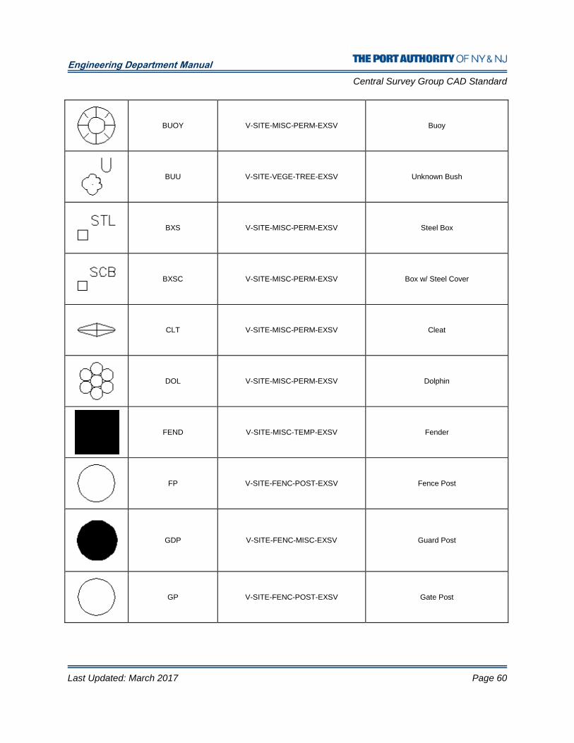
Engineering Department Manual
Central Survey Group CAD Standard
Last Updated: March 2017 Page 60
BUOY V-SITE-MISC-PERM-EXSV Buoy
BUU V-SITE-VEGE-TREE-EXSV Unknown Bush
BXS V-SITE-MISC-PERM-EXSV Steel Box
BXSC V-SITE-MISC-PERM-EXSV Box w/ Steel Cover
CLT V-SITE-MISC-PERM-EXSV Cleat
DOL V-SITE-MISC-PERM-EXSV Dolphin
FEND V-SITE-MISC-TEMP-EXSV Fender
FP V-SITE-FENC-POST-EXSV Fence Post
GDP V-SITE-FENC-MISC-EXSV Guard Post
GP V-SITE-FENC-POST-EXSV Gate Post
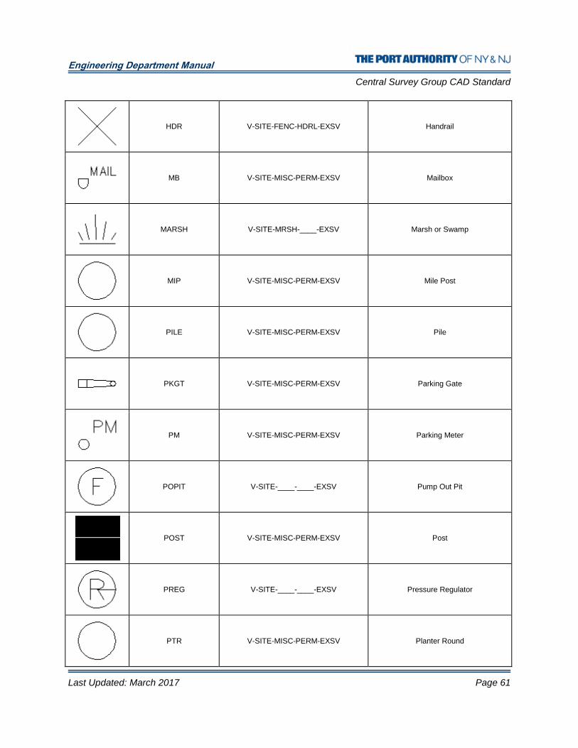
Engineering Department Manual
Central Survey Group CAD Standard
Last Updated: March 2017 Page 61
HDR V-SITE-FENC-HDRL-EXSV Handrail
MB V-SITE-MISC-PERM-EXSV Mailbox
MARSH V-SITE-MRSH-____-EXSV Marsh or Swamp
MIP V-SITE-MISC-PERM-EXSV Mile Post
PILE V-SITE-MISC-PERM-EXSV Pile
PKGT V-SITE-MISC-PERM-EXSV Parking Gate
PM V-SITE-MISC-PERM-EXSV Parking Meter
POPIT V-SITE-____-____-EXSV Pump Out Pit
POST V-SITE-MISC-PERM-EXSV Post
PREG V-SITE-____-____-EXSV Pressure Regulator
PTR V-SITE-MISC-PERM-EXSV Planter Round

Engineering Department Manual
Central Survey Group CAD Standard
Last Updated: March 2017 Page 62
PTS V-SITE-MISC-PERM-EXSV Planter Square
SD V-SITE-MISC-PERM-EXSV Satellite Dish
STAT V-SITE-MISC-PERM-EXSV Statue or Monument
STMP V-SITE-VEGE-TREE-EXSV Stump
TDN V-SITE-MISC-PERM-EXSV Tie Down
TICDIS V-SITE-____-____-EXSV Ticket Dispenser
TRC V-SITE-VEGE-TREE-EXSV Coniferous Tree
TRD V-SITE-VEGE-TREE-EXSV Deciduous Tree
TWR V-SITE-MISC-PERM-EXSV Tower
VENT V-SITE-MISC-PERM-EXSV Vent
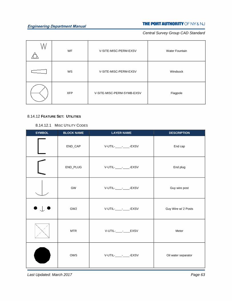
Engineering Department Manual
Central Survey Group CAD Standard
Last Updated: March 2017 Page 63
WF V-SITE-MISC-PERM-EXSV Water Fountain
WS V-SITE-MISC-PERM-EXSV Windsock
XFP V-SITE-MISC-PERM-SYMB-EXSV Flagpole
8.14.12 FEATURE SET: UTILITIES
8.14.12.1 MISC UTILITY CODES
SYMBOL BLOCK NAME LAYER NAME DESCRIPTION
END_CAP V-UTIL-____-____-EXSV End cap
END_PLUG V-UTIL-____-____-EXSV End plug
GW V-UTIL-____-____-EXSV Guy wire post
GW2 V-UTIL-____-____-EXSV Guy Wire w/ 2 Posts
MTR V-UTIL-____-____EXSV Meter
OWS V-UTIL-____-____-EXSV Oil water separator

Engineering Department Manual
Central Survey Group CAD Standard
Last Updated: March 2017 Page 64
PGOING V-UTIL-____-____-EXSV Ongoing pipe progression indicator
PMPSTA V-UTIL-____-____-EXSV Pump station
REDUC V-UTIL-____-____-EXSV Reducer
TEE V-UTIL-____-____-EXSV Tee
TH V-UTIL-____-____-EXSV Test Hole
TMKR V-UTIL-____-____-EXSV Temporary marker
WPO V-UTIL-____-____-EXSV Wood Utility Pole
WYE V-UTIL-____-____-EXSV Wye
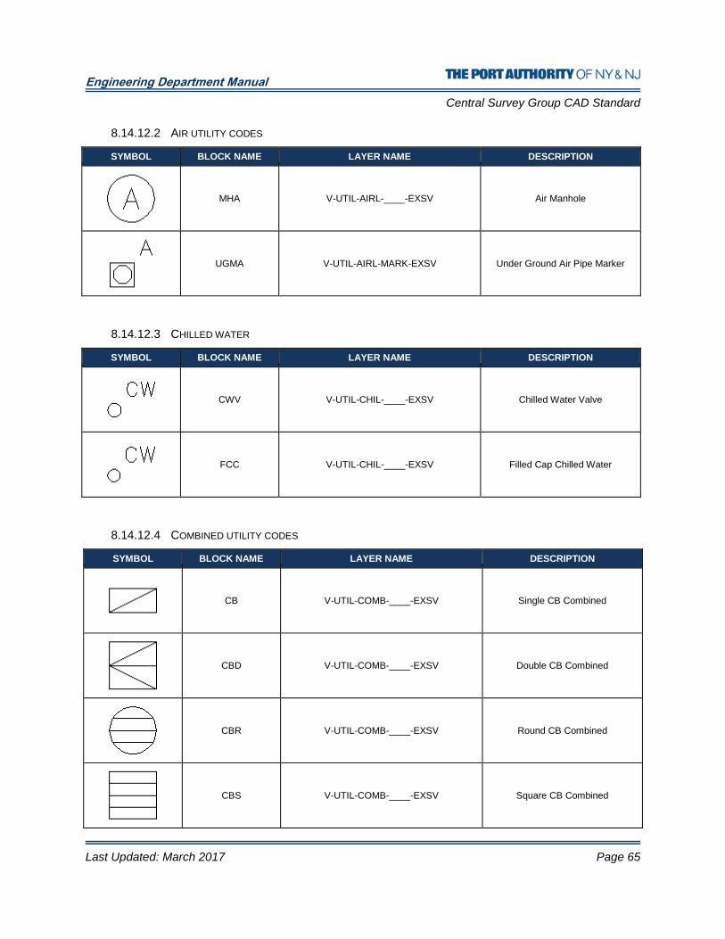
Engineering Department Manual
Central Survey Group CAD Standard
Last Updated: March 2017 Page 65
8.14.12.2 AIR UTILITY CODES
SYMBOL BLOCK NAME LAYER NAME DESCRIPTION
MHA V-UTIL-AIRL-____-EXSV Air Manhole
UGMA V-UTIL-AIRL-MARK-EXSV Under Ground Air Pipe Marker
8.14.12.3 CHILLED WATER
SYMBOL BLOCK NAME LAYER NAME DESCRIPTION
CWV V-UTIL-CHIL-____-EXSV Chilled Water Valve
FCC V-UTIL-CHIL-____-EXSV Filled Cap Chilled Water
8.14.12.4 COMBINED UTILITY CODES
SYMBOL BLOCK NAME LAYER NAME DESCRIPTION
CB V-UTIL-COMB-____-EXSV Single CB Combined
CBD V-UTIL-COMB-____-EXSV Double CB Combined
CBR V-UTIL-COMB-____-EXSV Round CB Combined
CBS V-UTIL-COMB-____-EXSV Square CB Combined
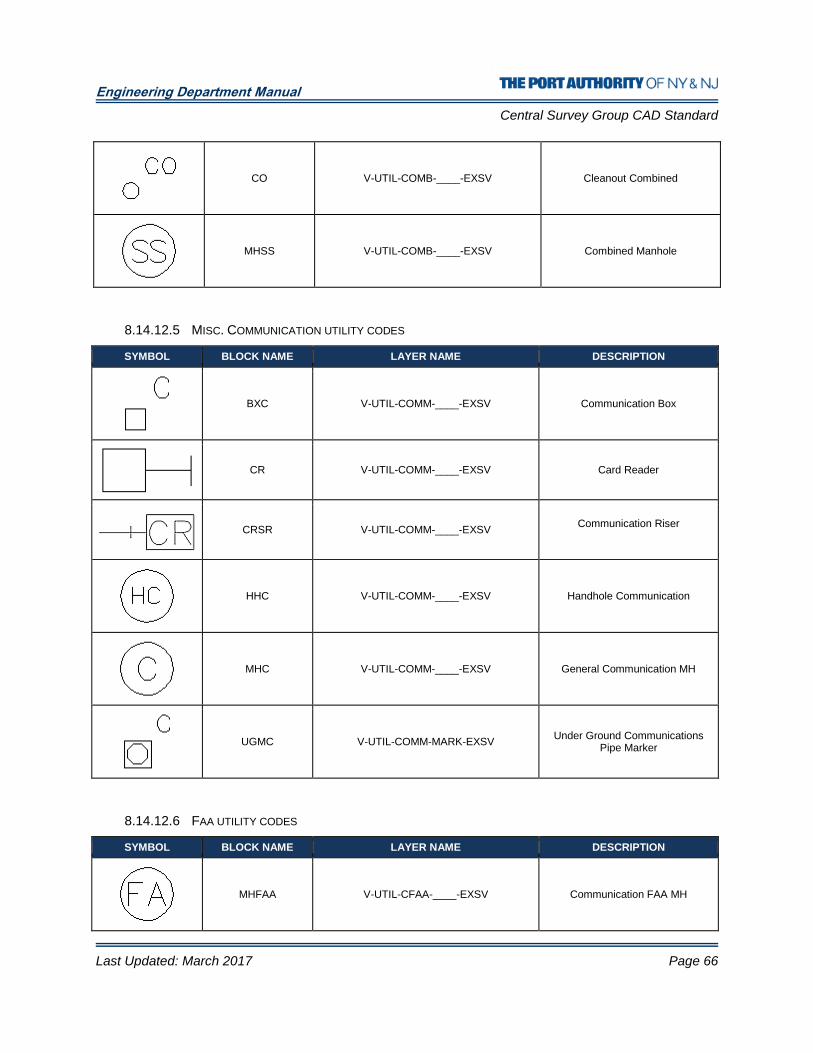
Engineering Department Manual
Central Survey Group CAD Standard
Last Updated: March 2017 Page 66
CO V-UTIL-COMB-____-EXSV Cleanout Combined
MHSS V-UTIL-COMB-____-EXSV Combined Manhole
8.14.12.5 MISC. COMMUNICATION UTILITY CODES
SYMBOL BLOCK NAME LAYER NAME DESCRIPTION
BXC V-UTIL-COMM-____-EXSV Communication Box
CR V-UTIL-COMM-____-EXSV Card Reader
CRSR V-UTIL-COMM-____-EXSV Communication Riser
HHC V-UTIL-COMM-____-EXSV Handhole Communication
MHC V-UTIL-COMM-____-EXSV General Communication MH
UGMC V-UTIL-COMM-MARK-EXSV Under Ground Communications
Pipe Marker
8.14.12.6 FAA UTILITY CODES
SYMBOL BLOCK NAME LAYER NAME DESCRIPTION
MHFAA V-UTIL-CFAA-____-EXSV Communication FAA MH

Engineering Department Manual
Central Survey Group CAD Standard
Last Updated: March 2017 Page 67
FAALOC V-UTIL-CFAA-____-EXSV FAA Localizer
8.14.12.7 FIRE UTILITY CODES
SYMBOL BLOCK NAME LAYER NAME DESCRIPTION
BXF V-UTIL-CFIR-____-EXSV Fire Pull Box
MHFI V-UTIL-CFIR-____-EXSV Communication Fire MH
WPF V-UTIL-CMFI-____-EXSV Wood Pole w/ Fire Box
UGMFI V-UTIL-CFIR-MARK-EXSV Under Ground Fire Pipe Marker
8.14.12.8 SECURITY UTILITY
SYMBOL BLOCK NAME LAYER NAME DESCRIPTION
MHSC V-UTIL-CSEC-____-EXSV Communication MH Security
8.14.12.9 TELEPHONE UTILITY
SYMBOL BLOCK NAME LAYER NAME DESCRIPTION
BXT V-UTIL-CTEL-____-EXSV Telephone Box
MHT V-UTIL-CTEL-____-EXSV Telephone MH
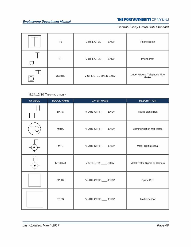
Engineering Department Manual
Central Survey Group CAD Standard
Last Updated: March 2017 Page 68
PB V-UTIL-CTEL-____-EXSV Phone Booth
PP V-UTIL-CTEL-____-EXSV Phone Post
UGMTE V-UTIL-CTEL-MARK-EXSV Under Ground Telephone Pipe
Marker
8.14.12.10 TRAFFIC UTILITY
SYMBOL BLOCK NAME LAYER NAME DESCRIPTION
BXTC V-UTIL-CTRF-____-EXSV Traffic Signal Box
MHTC V-UTIL-CTRF-____-EXSV Communication MH Traffic
MTL V-UTIL-CTRF-____-EXSV Metal Traffic Signal
MTLCAM V-UTIL-CTRF____-EXSV Metal Traffic Signal w/ Camera
SPLBX V-UTIL-CTRF-____-EXSV Splice Box
TRFS V-UTIL-CTRF-____-EXSV Traffic Sensor
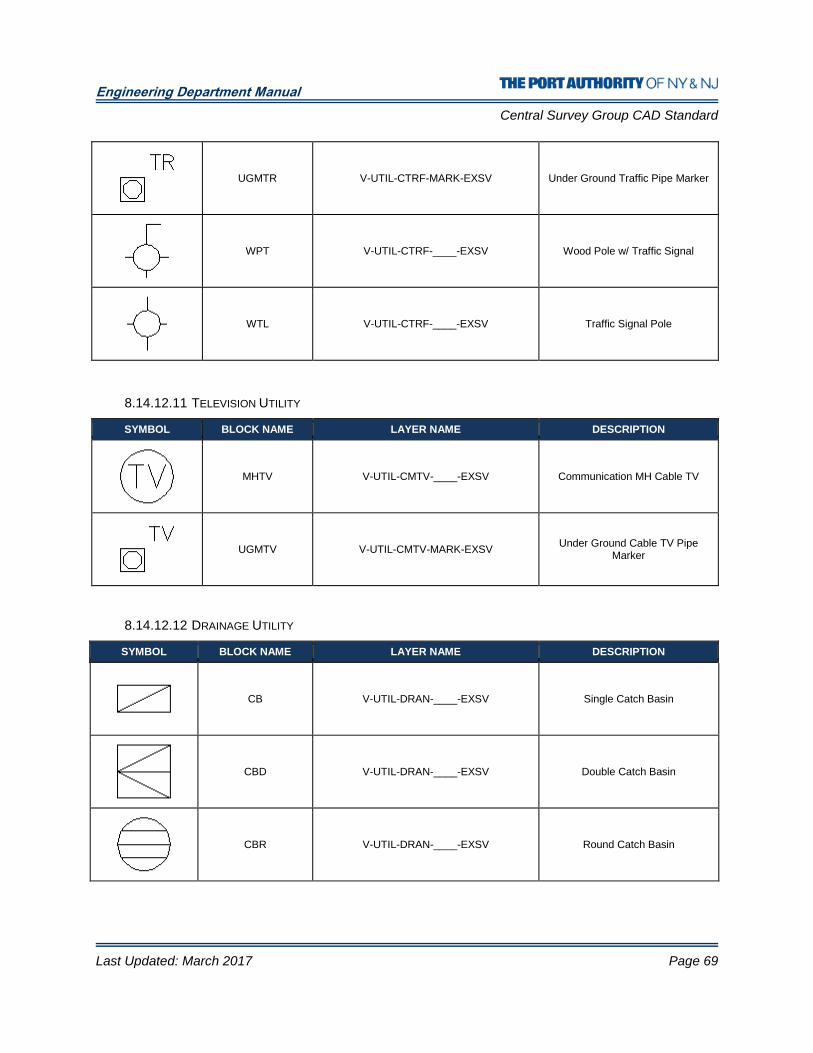
Engineering Department Manual
Central Survey Group CAD Standard
Last Updated: March 2017 Page 69
UGMTR V-UTIL-CTRF-MARK-EXSV Under Ground Traffic Pipe Marker
WPT V-UTIL-CTRF-____-EXSV Wood Pole w/ Traffic Signal
WTL V-UTIL-CTRF-____-EXSV Traffic Signal Pole
8.14.12.11 TELEVISION UTILITY
SYMBOL BLOCK NAME LAYER NAME DESCRIPTION
MHTV V-UTIL-CMTV-____-EXSV Communication MH Cable TV
UGMTV V-UTIL-CMTV-MARK-EXSV Under Ground Cable TV Pipe
Marker
8.14.12.12 DRAINAGE UTILITY
SYMBOL BLOCK NAME LAYER NAME DESCRIPTION
CB V-UTIL-DRAN-____-EXSV Single Catch Basin
CBD V-UTIL-DRAN-____-EXSV Double Catch Basin
CBR V-UTIL-DRAN-____-EXSV Round Catch Basin

Engineering Department Manual
Central Survey Group CAD Standard
Last Updated: March 2017 Page 70
CBS V-UTIL-DRAN-____-EXSV Square Catch Basin
DISUMP V-UTIL-DRAN-____-EXSV De-Icing Sump
DIV V-UTIL-DRAN-____-EXSV De-Icing Storm Valve`
DMTR V-UTIL-DRAN-____-EXSV Mitered End
DRN V-UTIL-DRAN-____-EXSV Drain or Scupper
DRS V-UTIL-DRAN-____-EXSV Drainage Sump
DV V-UTIL-DRAN-____-EXSV Drainage Valve
HEADWL V-UTIL-DRAN-____-EXSV Headwall
MHD V-UTIL-DRAN-____-EXSV Storm Drainage MH
MHGD V-UTIL-DRAN-____-EXSV Storm Drainage MH with Square or
Rectangle Base
OR V-UTIL-DRAN-____-EXSV Observation Riser
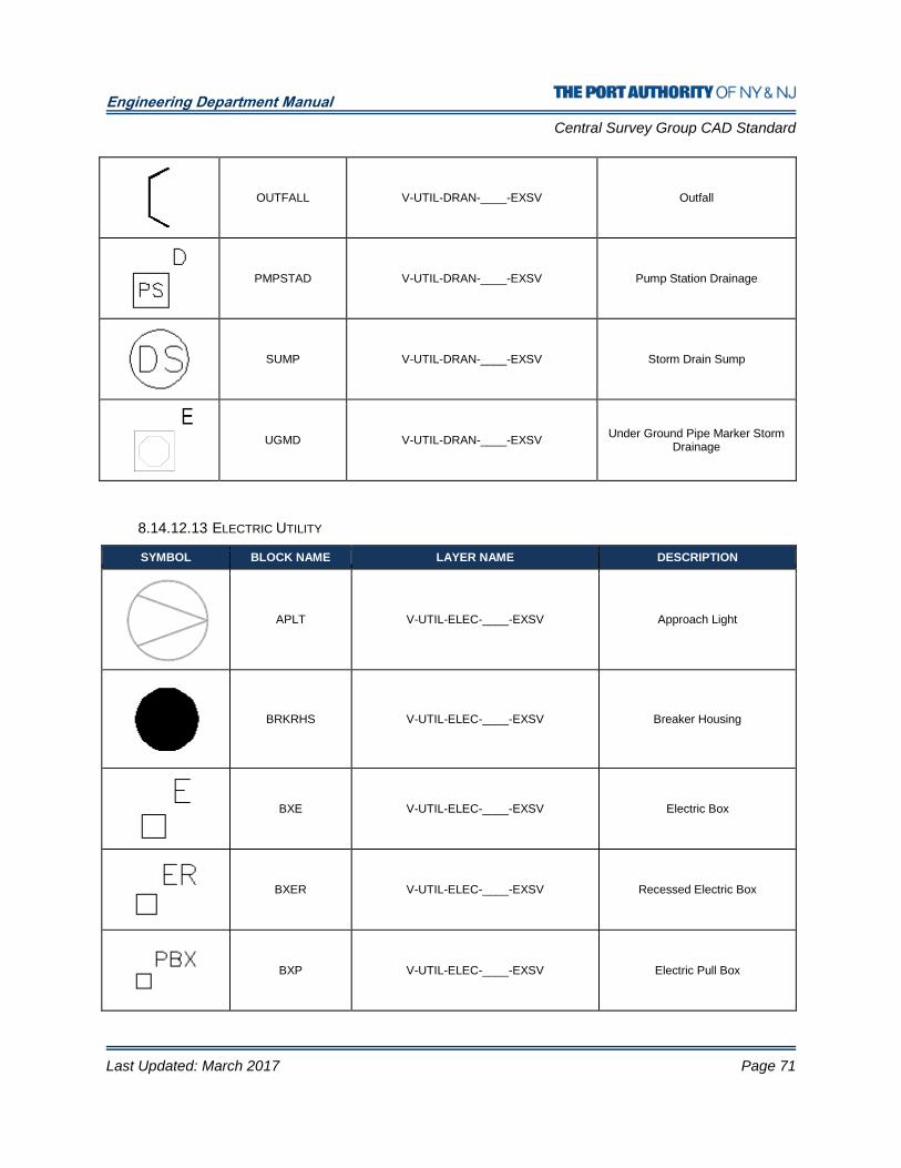
Engineering Department Manual
Central Survey Group CAD Standard
Last Updated: March 2017 Page 71
OUTFALL V-UTIL-DRAN-____-EXSV Outfall
PMPSTAD V-UTIL-DRAN-____-EXSV Pump Station Drainage
SUMP V-UTIL-DRAN-____-EXSV Storm Drain Sump
UGMD V-UTIL-DRAN-____-EXSV Under Ground Pipe Marker Storm
Drainage
8.14.12.13 ELECTRIC UTILITY
SYMBOL BLOCK NAME LAYER NAME DESCRIPTION
APLT V-UTIL-ELEC-____-EXSV Approach Light
BRKRHS V-UTIL-ELEC-____-EXSV Breaker Housing
BXE V-UTIL-ELEC-____-EXSV Electric Box
BXER V-UTIL-ELEC-____-EXSV Recessed Electric Box
BXP V-UTIL-ELEC-____-EXSV Electric Pull Box

Engineering Department Manual
Central Survey Group CAD Standard
Last Updated: March 2017 Page 72
EGATE V-UTIL-ELEC-____-EXSV Electrical Gate
EM V-UTIL-ELEC-____-EXSV Electric Meter
EMP V-UTIL-ELEC-____-EXSV Electric Meter Pit
ERSR V-UTIL-ELEC-____-EXSV Electrical Riser
GEN V-UTIL-ELEC-____-EXSV Generator
HHE V-UTIL-ELEC-____-EXSV Handhole Electrical
LP V-UTIL-ELEC-____-EXSV Private Lamp Post
LT V-UTIL-ELEC-____-EXSV Light
LTWR V-UTIL-ELEC-____-EXSV Low Press Water Line
MHE V-UTIL-ELEC-____-EXSV Electric MH

Engineering Department Manual
Central Survey Group CAD Standard
Last Updated: March 2017 Page 73
MLP V-UTIL-ELEC-____-EXSV Metal Single Street Light Tower
MP10L V-UTIL-ELEC-____-EXSV Metal 10 Light Tower
MP2L V-UTIL-ELEC-____-EXSV Metal Double Light Tower
MP3L V-UTIL-ELEC-____-EXSV Metal Triple Light Tower
MP4L V-UTIL-ELEC-____-EXSV Metal Four Light Tower
MPED V-UTIL-ELEC-____-EXSV Metal w/ PED Light
RWCLT V-UTIL-ELEC-____-EXSV Runway CL Light
RWELT V-UTIL-ELEC-____-EXSV Runway Edge Light
RWHLT V-UTIL-ELEC-____-EXSV Runway Hold Light
RWLT V-UTIL-ELEC-____-EXSV Runway Light
SSCC V-UTIL-ELEC-____-EXSV Surveillance Sys Control Cabinet
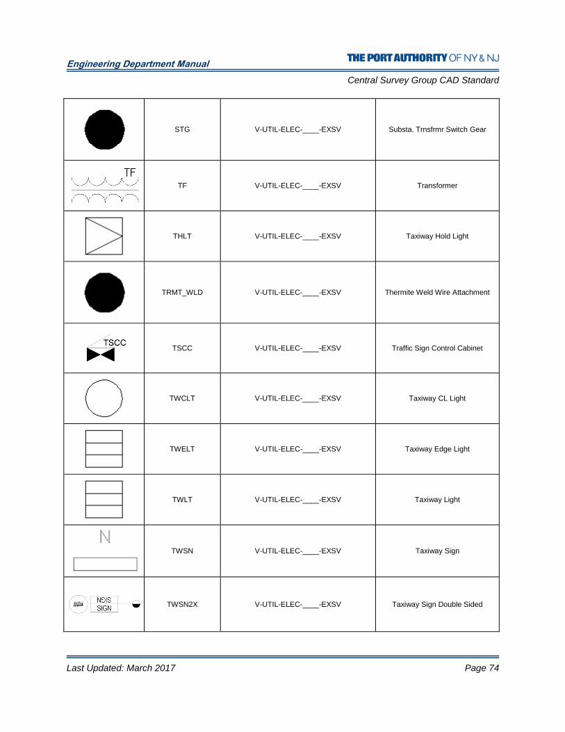
Engineering Department Manual
Central Survey Group CAD Standard
Last Updated: March 2017 Page 74
STG V-UTIL-ELEC-____-EXSV Substa. Trnsfrmr Switch Gear
TF V-UTIL-ELEC-____-EXSV Transformer
THLT V-UTIL-ELEC-____-EXSV Taxiway Hold Light
TRMT_WLD V-UTIL-ELEC-____-EXSV Thermite Weld Wire Attachment
TSCC V-UTIL-ELEC-____-EXSV Traffic Sign Control Cabinet
TWCLT V-UTIL-ELEC-____-EXSV Taxiway CL Light
TWELT V-UTIL-ELEC-____-EXSV Taxiway Edge Light
TWLT V-UTIL-ELEC-____-EXSV Taxiway Light
TWSN V-UTIL-ELEC-____-EXSV Taxiway Sign
TWSN2X V-UTIL-ELEC-____-EXSV Taxiway Sign Double Sided

Engineering Department Manual
Central Survey Group CAD Standard
Last Updated: March 2017 Page 75
UGME V-UTIL-ELEC-MARK-EXSV Under Ground Electrical Pipe
Marker
VASI V-UTIL-ELEC-____-EXSV Vasi Light
VMCC V-UTIL-ELEC-____-EXSV Variable Message Control Cabinet
WLP V-UTIL-ELEC-____-EXSV Wood Pole w/ Street Light
WP2L V-UTIL-ELEC-____-EXSV Wood Pole w/ 2 Lights
8.14.12.14 CATHODIC PROTECTION UTILITY
SYMBOL BLOCK NAME LAYER NAME DESCRIPTION
CPPDAG V-UTIL-ELCP-____-EXSV Cath Pro Deep Anode Grounded
CPPREH V-UTIL-ELCP-____-EXSV Cath Pro Perm Ref Electrode Horz
CPPREV V-UTIL-ELCP-____-EXSV Cath Pro Perm Ref Electrode Vert
CPTS-FM V-UTIL-ELCP-____-EXSV Cath Pro Test Sta Flush-Mounted
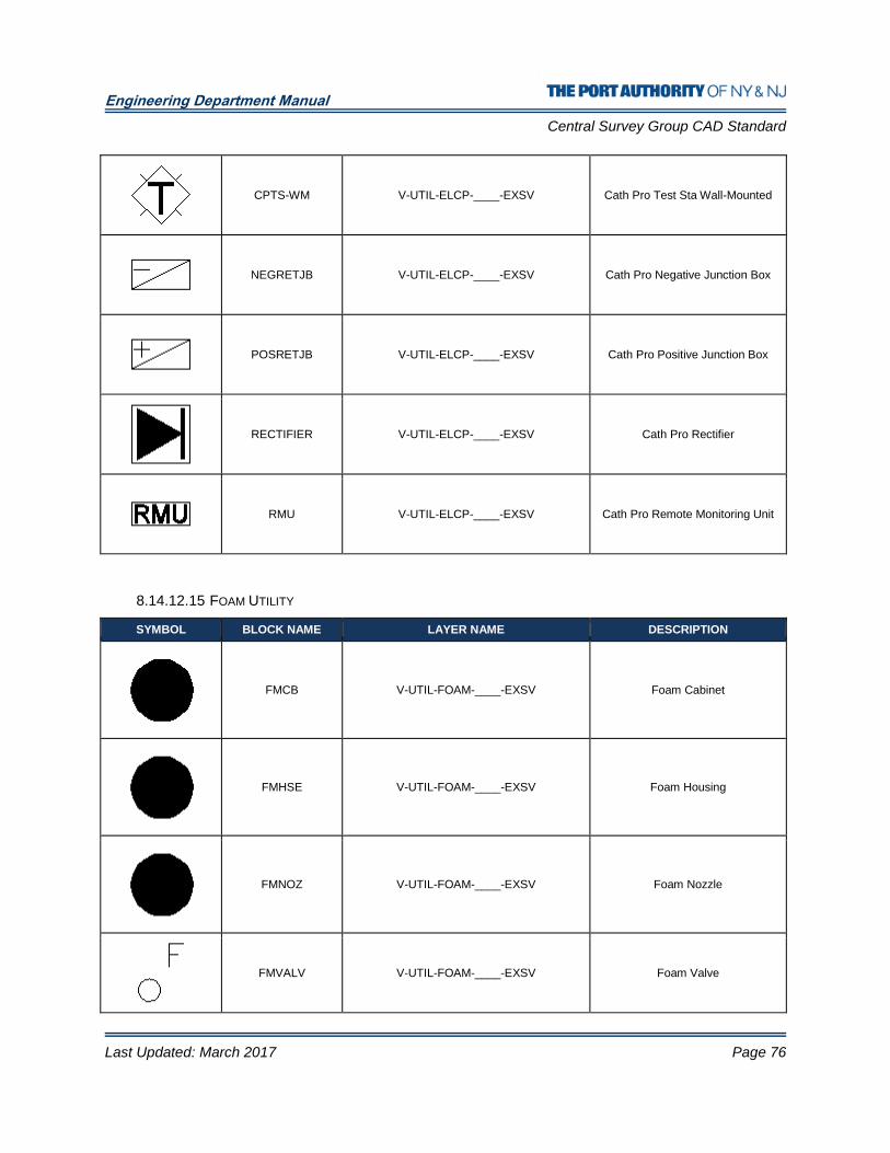
Engineering Department Manual
Central Survey Group CAD Standard
Last Updated: March 2017 Page 76
CPTS-WM V-UTIL-ELCP-____-EXSV Cath Pro Test Sta Wall-Mounted
NEGRETJB V-UTIL-ELCP-____-EXSV Cath Pro Negative Junction Box
POSRETJB V-UTIL-ELCP-____-EXSV Cath Pro Positive Junction Box
RECTIFIER V-UTIL-ELCP-____-EXSV Cath Pro Rectifier
RMU V-UTIL-ELCP-____-EXSV Cath Pro Remote Monitoring Unit
8.14.12.15 FOAM UTILITY
SYMBOL BLOCK NAME LAYER NAME DESCRIPTION
FMCB V-UTIL-FOAM-____-EXSV Foam Cabinet
FMHSE V-UTIL-FOAM-____-EXSV Foam Housing
FMNOZ V-UTIL-FOAM-____-EXSV Foam Nozzle
FMVALV V-UTIL-FOAM-____-EXSV Foam Valve
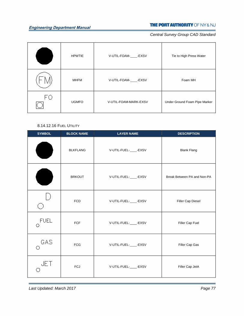
Engineering Department Manual
Central Survey Group CAD Standard
Last Updated: March 2017 Page 77
HPWTIE V-UTIL-FOAM-____-EXSV Tie to High Press Water
MHFM V-UTIL-FOAM-____-EXSV Foam MH
UGMFO V-UTIL-FOAM-MARK-EXSV Under Ground Foam Pipe Marker
8.14.12.16 FUEL UTILITY
SYMBOL BLOCK NAME LAYER NAME DESCRIPTION
BLKFLANG V-UTIL-FUEL-____-EXSV Blank Flang
BRKOUT V-UTIL-FUEL-____-EXSV Break Between PA and Non-PA
FCD V-UTIL-FUEL-____-EXSV Filler Cap Diesel
FCF V-UTIL-FUEL-____-EXSV Filler Cap Fuel
FCG V-UTIL-FUEL-____-EXSV Filler Cap Gas
FCJ V-UTIL-FUEL-____-EXSV Filler Cap JetA
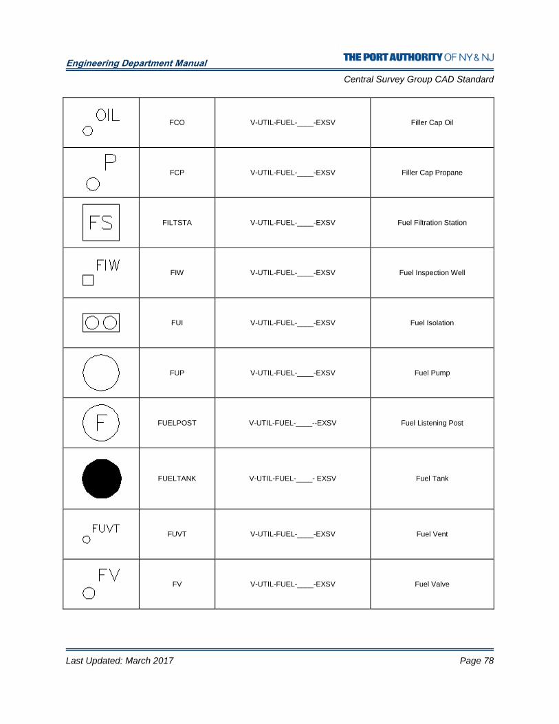
Engineering Department Manual
Central Survey Group CAD Standard
Last Updated: March 2017 Page 78
FCO V-UTIL-FUEL-____-EXSV Filler Cap Oil
FCP V-UTIL-FUEL-____-EXSV Filler Cap Propane
FILTSTA V-UTIL-FUEL-____-EXSV Fuel Filtration Station
FIW V-UTIL-FUEL-____-EXSV Fuel Inspection Well
FUI V-UTIL-FUEL-____-EXSV Fuel Isolation
FUP V-UTIL-FUEL-____-EXSV Fuel Pump
FUELPOST V-UTIL-FUEL-____--EXSV Fuel Listening Post
FUELTANK V-UTIL-FUEL-____- EXSV Fuel Tank
FUVT V-UTIL-FUEL-____-EXSV Fuel Vent
FV V-UTIL-FUEL-____-EXSV Fuel Valve
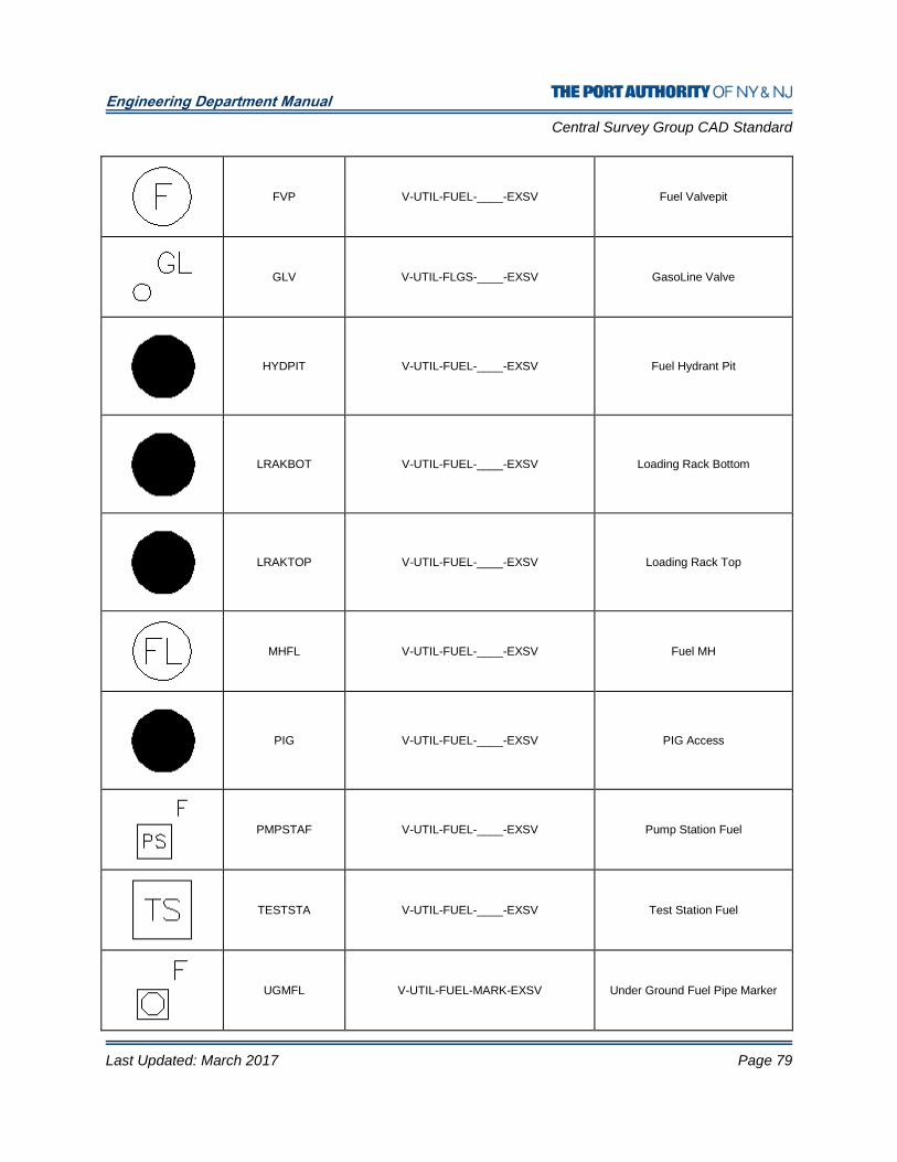
Engineering Department Manual
Central Survey Group CAD Standard
Last Updated: March 2017 Page 79
FVP V-UTIL-FUEL-____-EXSV Fuel Valvepit
GLV V-UTIL-FLGS-____-EXSV GasoLine Valve
HYDPIT V-UTIL-FUEL-____-EXSV Fuel Hydrant Pit
LRAKBOT V-UTIL-FUEL-____-EXSV Loading Rack Bottom
LRAKTOP V-UTIL-FUEL-____-EXSV Loading Rack Top
MHFL V-UTIL-FUEL-____-EXSV Fuel MH
PIG V-UTIL-FUEL-____-EXSV PIG Access
PMPSTAF V-UTIL-FUEL-____-EXSV Pump Station Fuel
TESTSTA V-UTIL-FUEL-____-EXSV Test Station Fuel
UGMFL V-UTIL-FUEL-MARK-EXSV Under Ground Fuel Pipe Marker
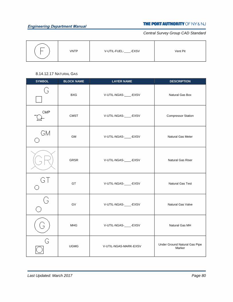
Engineering Department Manual
Central Survey Group CAD Standard
Last Updated: March 2017 Page 80
VNTP V-UTIL-FUEL-____-EXSV Vent Pit
8.14.12.17 NATURAL GAS
SYMBOL BLOCK NAME LAYER NAME DESCRIPTION
BXG V-UTIL-NGAS-____-EXSV Natural Gas Box
CMST V-UTIL-NGAS-____-EXSV Compressor Station
GM V-UTIL-NGAS-____-EXSV Natural Gas Meter
GRSR V-UTIL-NGAS-____-EXSV Natural Gas Riser
GT V-UTIL-NGAS-____-EXSV Natural Gas Test
GV V-UTIL-NGAS-____-EXSV Natural Gas Valve
MHG V-UTIL-NGAS-____-EXSV Natural Gas MH
UGMG V-UTIL-NGAS-MARK-EXSV Under Ground Natural Gas Pipe
Marker
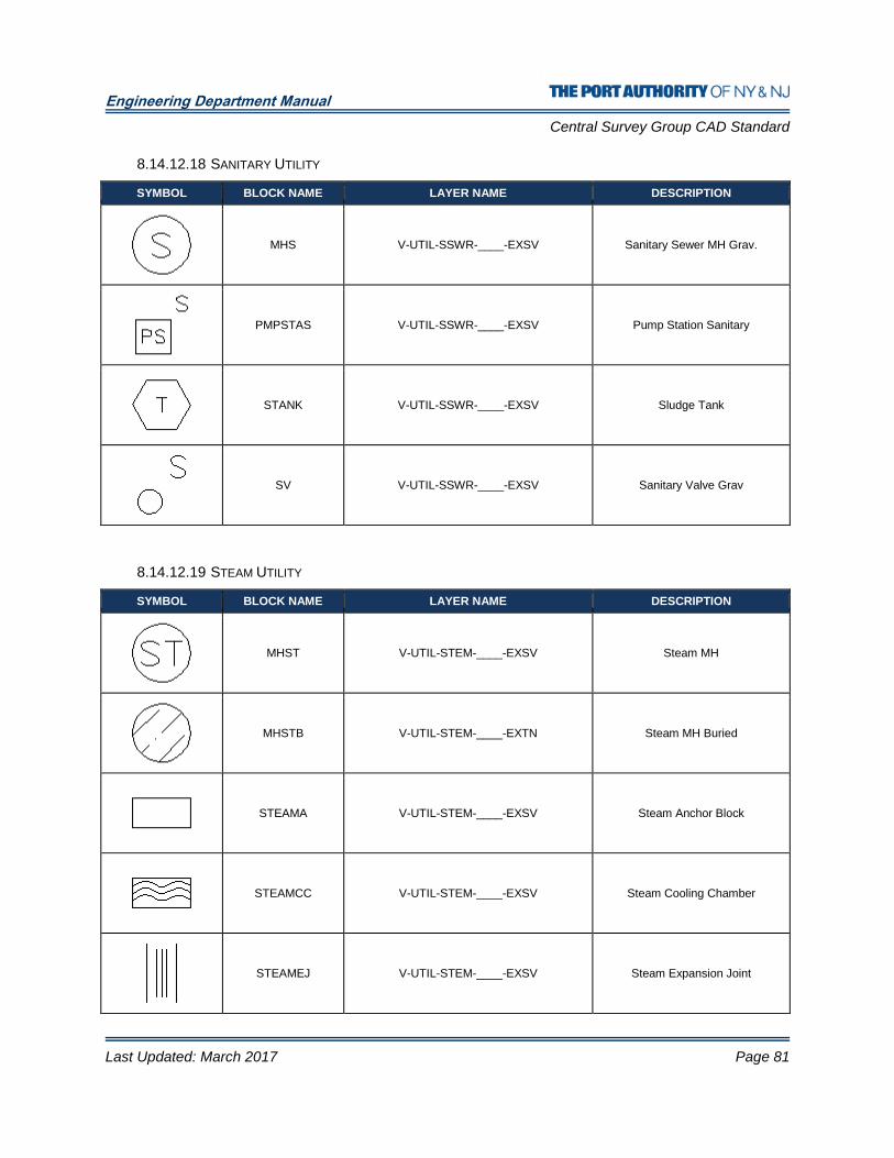
Engineering Department Manual
Central Survey Group CAD Standard
Last Updated: March 2017 Page 81
8.14.12.18 SANITARY UTILITY
SYMBOL BLOCK NAME LAYER NAME DESCRIPTION
MHS V-UTIL-SSWR-____-EXSV Sanitary Sewer MH Grav.
PMPSTAS V-UTIL-SSWR-____-EXSV Pump Station Sanitary
STANK V-UTIL-SSWR-____-EXSV Sludge Tank
SV V-UTIL-SSWR-____-EXSV Sanitary Valve Grav
8.14.12.19 STEAM UTILITY
SYMBOL BLOCK NAME LAYER NAME DESCRIPTION
MHST V-UTIL-STEM-____-EXSV Steam MH
MHSTB V-UTIL-STEM-____-EXTN Steam MH Buried
STEAMA V-UTIL-STEM-____-EXSV Steam Anchor Block
STEAMCC V-UTIL-STEM-____-EXSV Steam Cooling Chamber
STEAMEJ V-UTIL-STEM-____-EXSV Steam Expansion Joint
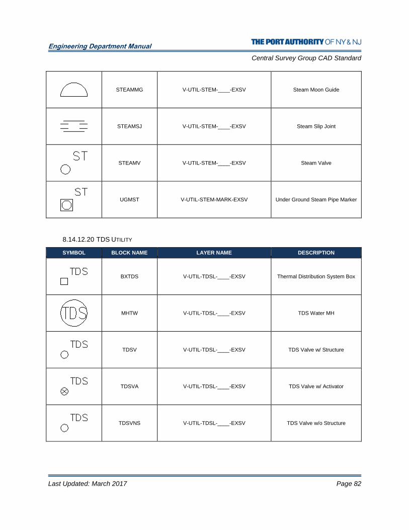
Engineering Department Manual
Central Survey Group CAD Standard
Last Updated: March 2017 Page 82
STEAMMG V-UTIL-STEM-____-EXSV Steam Moon Guide
STEAMSJ V-UTIL-STEM-____-EXSV Steam Slip Joint
STEAMV V-UTIL-STEM-____-EXSV Steam Valve
UGMST V-UTIL-STEM-MARK-EXSV Under Ground Steam Pipe Marker
8.14.12.20 TDS UTILITY
SYMBOL BLOCK NAME LAYER NAME DESCRIPTION
BXTDS V-UTIL-TDSL-____-EXSV Thermal Distribution System Box
MHTW V-UTIL-TDSL-____-EXSV TDS Water MH
TDSV V-UTIL-TDSL-____-EXSV TDS Valve w/ Structure
TDSVA V-UTIL-TDSL-____-EXSV TDS Valve w/ Activator
TDSVNS V-UTIL-TDSL-____-EXSV TDS Valve w/o Structure

Engineering Department Manual
Central Survey Group CAD Standard
Last Updated: March 2017 Page 83
UGMTD V-UTIL-TDSL-MARK-EXSV Under Ground TDS Pipe Marker
VPTM V-UTIL-TDSL-____-EXSV TDS Valve Pit Manhole
8.14.12.21 UNKNOWN UTILITY
SYMBOL BLOCK NAME LAYER NAME DESCRIPTION
BXU V-UTIL-UKWN-____-EXSV Unknown Box
CROSS V-UTIL-UKWN-____-EXSV Four Way Tee
FCU V-UTIL-UKWN-____-EXSV Filler Cap Unknown
HH V-UTIL-UKWN-____-EXSV Handhole
MH V-UTIL-UKWN-____-EXSV Manhole
MHPS V-UTIL-UKWN-____-EXSV Manhole Public Service
TEE V-UTIL-UKWN-____-EXSV Tee Unknown
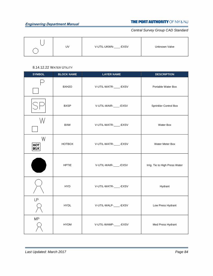
Engineering Department Manual
Central Survey Group CAD Standard
Last Updated: March 2017 Page 84
UV V-UTIL-UKWN-____-EXSV Unknown Valve
8.14.12.22 WATER UTILITY
SYMBOL BLOCK NAME LAYER NAME DESCRIPTION
BXH2O V-UTIL-WATR-____-EXSV Portable Water Box
BXSP V-UTIL-WAIR-____-EXSV Sprinkler Control Box
BXW V-UTIL-WATR-____-EXSV Water Box
HOTBOX V-UTIL-WATR-____-EXSV Water Meter Box
HPTIE V-UTIL-WAIR-____-EXSV Irrig. Tie to High Press Water
HYD V-UTIL-WATR-____-EXSV Hydrant
HYDL V-UTIL-WALP-____-EXSV Low Press Hydrant
HYDM V-UTIL-WAMP-____-EXSV Med Press Hydrant
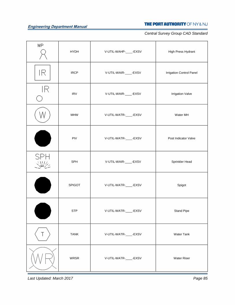
Engineering Department Manual
Central Survey Group CAD Standard
Last Updated: March 2017 Page 85
HYDH V-UTIL-WAHP-____-EXSV High Press Hydrant
IRCP V-UTIL-WAIR-____-EXSV Irrigation Control Panel
IRV V-UTIL-WAIR-____-EXSV Irrigation Valve
MHW V-UTIL-WATR-____-EXSV Water MH
PIV V-UTIL-WATR-____-EXSV Post Indicator Valve
SPH V-UTIL-WAIR-____-EXSV Sprinkler Head
SPIGOT V-UTIL-WATR-____-EXSV Spigot
STP V-UTIL-WATR-____-EXSV Stand Pipe
TANK V-UTIL-WATR-____-EXSV Water Tank
WRSR V-UTIL-WATR-____-EXSV Water Riser

Engineering Department Manual
Central Survey Group CAD Standard
Last Updated: March 2017 Page 86
WV V-UTIL-WATR-____-EXSV Water Valve
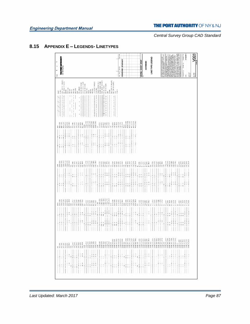
Engineering Department Manual
Central Survey Group CAD Standard
Last Updated: March 2017 Page 87
8.15 APPENDIX E – LEGENDS- LINETYPES
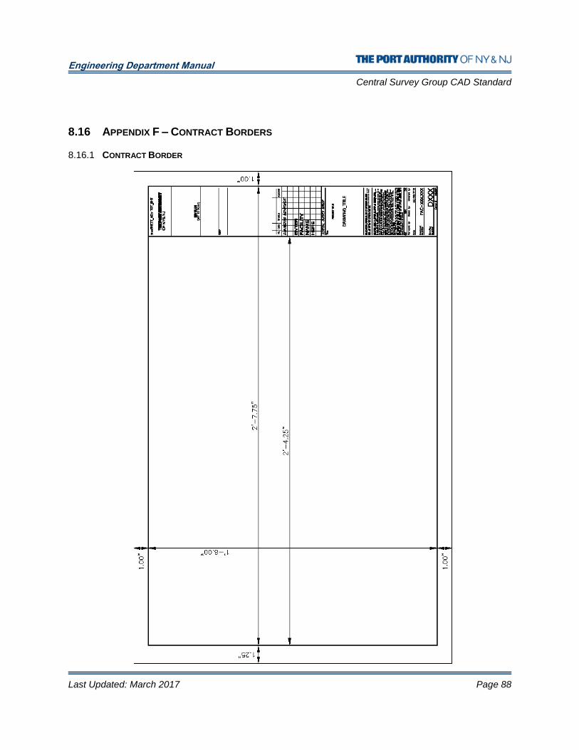
Engineering Department Manual
Central Survey Group CAD Standard
Last Updated: March 2017 Page 88
8.16 APPENDIX F – CONTRACT BORDERS
8.16.1 CONTRACT BORDER
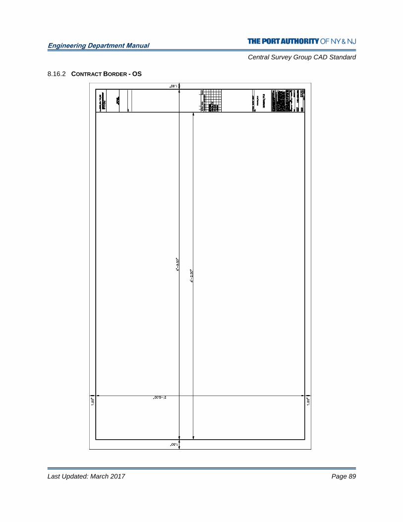
Engineering Department Manual
Central Survey Group CAD Standard
Last Updated: March 2017 Page 89
8.16.2 CONTRACT BORDER - OS
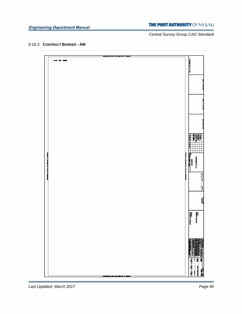
Engineering Department Manual
Central Survey Group CAD Standard
Last Updated: March 2017 Page 90
8.16.3 CONTRACT BORDER - AM
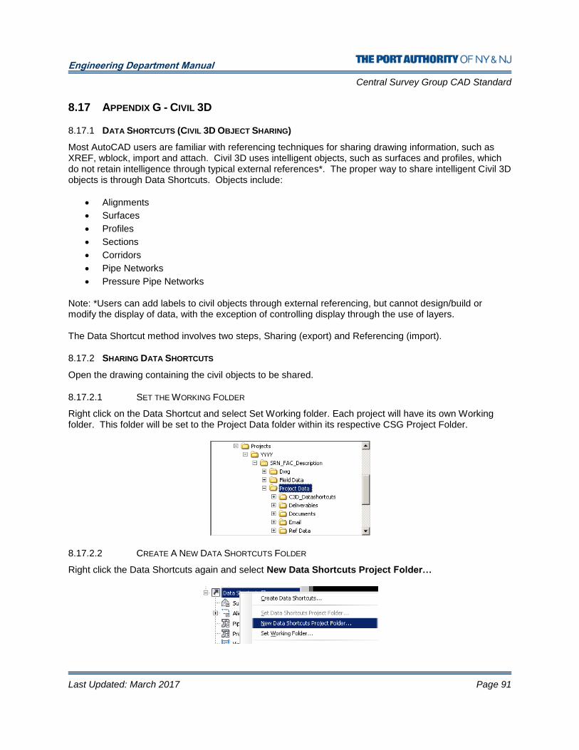
Engineering Department Manual
Central Survey Group CAD Standard
Last Updated: March 2017 Page 91
8.17 APPENDIX G - CIVIL 3D
8.17.1 DATA SHORTCUTS (CIVIL 3D OBJECT SHARING)
Most AutoCAD users are familiar with referencing techniques for sharing drawing information, such as XREF, wblock, import and attach. Civil 3D uses intelligent objects, such as surfaces and profiles, which do not retain intelligence through typical external references*. The proper way to share intelligent Civil 3D objects is through Data Shortcuts. Objects include:
Alignments
Surfaces
Profiles
Sections
Corridors
Pipe Networks
Pressure Pipe Networks
Note: *Users can add labels to civil objects through external referencing, but cannot design/build or modify the display of data, with the exception of controlling display through the use of layers. The Data Shortcut method involves two steps, Sharing (export) and Referencing (import).
8.17.2 SHARING DATA SHORTCUTS
Open the drawing containing the civil objects to be shared.
8.17.2.1 SET THE WORKING FOLDER
Right click on the Data Shortcut and select Set Working folder. Each project will have its own Working folder. This folder will be set to the Project Data folder within its respective CSG Project Folder.
8.17.2.2 CREATE A NEW DATA SHORTCUTS FOLDER
Right click the Data Shortcuts again and select New Data Shortcuts Project Folder…
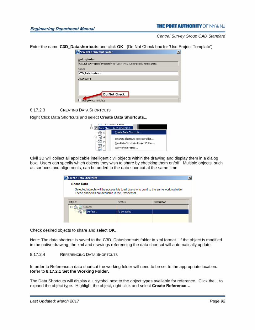
Engineering Department Manual
Central Survey Group CAD Standard
Last Updated: March 2017 Page 92
Enter the name C3D_Datashortcuts and click OK. (Do Not Check box for ‘Use Project Template’)
8.17.2.3 CREATING DATA SHORTCUTS
Right Click Data Shortcuts and select Create Data Shortcuts...
Civil 3D will collect all applicable intelligent civil objects within the drawing and display them in a dialog box. Users can specify which objects they wish to share by checking them on/off. Multiple objects, such as surfaces and alignments, can be added to the data shortcut at the same time.
Check desired objects to share and select OK. Note: The data shortcut is saved to the C3D_Datashortcuts folder in xml format. If the object is modified in the native drawing, the xml and drawings referencing the data shortcut will automatically update.
8.17.2.4 REFERENCING DATA SHORTCUTS
In order to Reference a data shortcut the working folder will need to be set to the appropriate location. Refer to 8.17.2.1 Set the Working Folder. The Data Shortcuts will display a + symbol next to the object types available for reference. Click the + to expand the object type. Highlight the object, right click and select Create Reference…
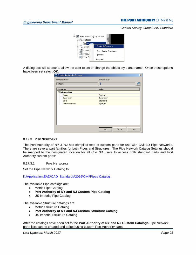
Engineering Department Manual
Central Survey Group CAD Standard
Last Updated: March 2017 Page 93
A dialog box will appear to allow the user to set or change the object style and name. Once these options have been set select OK.
8.17.3 PIPE NETWORKS
The Port Authority of NY & NJ has compiled sets of custom parts for use with Civil 3D Pipe Networks. There are several part families for both Pipes and Structures. The Pipe Network Catalog Settings should be mapped to the designated location for all Civil 3D users to access both standard parts and Port Authority custom parts:
8.17.3.1 PIPE NETWORKS
Set the Pipe Network Catalog to: K:\Application\EAD\CAD_Standards\2016\Civil\Pipes Catalog The available Pipe catalogs are:
Metric Pipe Catalog
Port Authority of NY and NJ Custom Pipe Catalog
US Imperial Pipe Catalog The available Structure catalogs are:
Metric Structure Catalog
Port Authority of NY and NJ Custom Structure Catalog
US Imperial Structure Catalog
After the catalogs have been set to the Port Authority of NY and NJ Custom Catalogs Pipe Network parts lists can be created and edited using custom Port Authority parts.
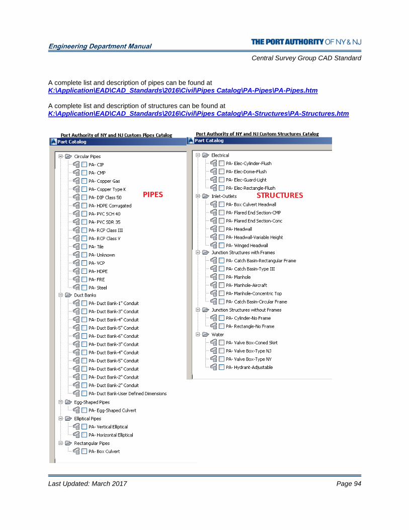
Engineering Department Manual
Central Survey Group CAD Standard
Last Updated: March 2017 Page 94
A complete list and description of pipes can be found at K:\Application\EAD\CAD_Standards\2016\Civil\Pipes Catalog\PA-Pipes\PA-Pipes.htm A complete list and description of structures can be found at K:\Application\EAD\CAD_Standards\2016\Civil\Pipes Catalog\PA-Structures\PA-Structures.htm
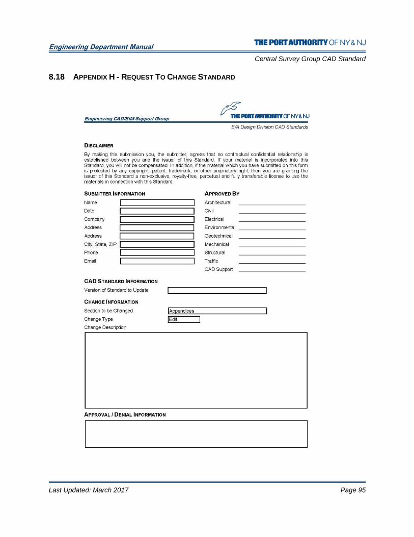
Engineering Department Manual
Central Survey Group CAD Standard
Last Updated: March 2017 Page 95
8.18 APPENDIX H - REQUEST TO CHANGE STANDARD
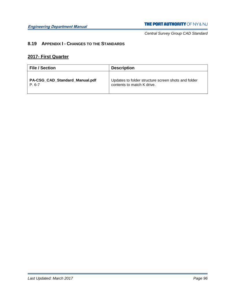
Engineering Department Manual
Central Survey Group CAD Standard
Last Updated: March 2017 Page 96
8.19 APPENDIX I - CHANGES TO THE STANDARDS
2017- First Quarter
File / Section Description
PA-CSG_CAD_Standard_Manual.pdf P. 6-7
Updates to folder structure screen shots and folder contents to match K drive.


