Centrifugal Pump with Volute Casing Original Operating Manual NIM / NAM series Version BA-2014.09 ID-No. 550 018 VM-No. 467.0001 GB ALLWEILER GmbH Postfach 1140 Allweilerstr. 1 78301 Radolfzell Germany Phone: +49 (0) 7732-86-0 Fax: +49 (0) 7732-86-436 Email: [email protected]Internet: http://www.allweiler.com We reserve the right to make technical changes. Read carefully before use. Save for future use.
Transcript
Centrifugal Pump withVolute CasingOriginal Operating Manual NIM / NAM series
Version BA-2014.09ID-No. 550 018VM-No. 467.0001 GB
4 NIM / NAM series BA-2014.09 467.0001 GB – 550 018
About this document
1 About this document
This manual
• Is part of the pump
• Applies to the afore-mentioned pump series
• Describes safe and appropriate operation during all oper-ating phases
1.1 Target groups
Target group Duty
Operating company Keep this manual available at the site of operation of the system,including for later use.
Ensure that personnel read and follow the instructions in thismanual and the other applicable documents, especially all safetyinstructions and warnings.
Observe any additional rules and regulations referring to thesystem.
Qualified personnel, fitter Read, observe and follow this manual and the other applicabledocuments, especially all safety instructions and warnings.
Tab. 1 Target groups and their duties
1.2 Other applicable documents
Document Purpose
Order data sheet Technical specifications, conditions of operation
Setup drawing Setup dimensions, connection dimensions etc.
Supplier documentation Technical documentation for parts supplied by subcontractors
Spare parts list Ordering spare parts
Declaration of conformity Conformity with standardsContents of the declaration of conformity (→ 9.5 Declaration ofconformity according to EC machine directives, Page 43).
Tab. 2 Other applicable documents and their purpose
467.0001 GB – 550 018 BA-2014.09 NIM / NAM series 5
CAUTIONPotentially hazardous situation Minor bodily harm
NOTEPotentially hazardous situation Material damage
Tab. 3 Warnings and consequences of disregarding them
Symbol Meaning
Safety warning sign
Take note of all information highlighted by the safety warning signand follow the instructions to avoid injury or death.
Instruction
1. , 2. , ... Multiple-step instructions
Precondition
→ Cross reference
Information, advice
Tab. 4 Symbols and their meaning
1.4 Technical terms
Term Meaning
Sealing medium Medium as seal barrier/buffer fluid or for quenching of shaft seals
Auxiliary systems Systems for operating the pump
Tab. 5 Technical terms and their meaning
6 NIM / NAM series BA-2014.09 467.0001 GB – 550 018
Safety
2 Safety
The manufacturer does not accept any liability for damageresulting from disregard of the entire documentation.
2.1 Intended use
• Only use the pump for pumping the agreed pumped media(→ order data sheet).
• Adhere to the operating limits and size-dependent mini-mum flow rate.
• Avoid dry running:Initial damage, such as destruction of the mechanical sealand plastic parts, will occur within only a few seconds.– Make sure the pump is only operated with, and never
without, a pumped medium.
• Avoid cavitation:– Fully open the suction-side armature and do not use it
to adjust the flow rate.– Do not open the pressure-side armature beyond the
agreed operating point.
• Avoid overheating:– Do not operate the pump while the pressure-side arma-
ture is closed.– Observe the minimum flow rate (→ order data sheet).
• Avoid damage to the motor:– Do not open the pressure-side armature beyond the
agreed operating point.– Note the maximum permissible number of times the
motor can be switched on per hour (→ manufacturer'sspecifications).
• Consult the manufacturer about any other use of the pump.
• When a pump is delivered without a motor, the pump unitmust be completed in accordance with the stipulations ofmachine directive 2006/42/EC.
Prevention of obvious misuse (examples)
• Note the operating limits of the pump concerning temper-ature, pressure, flow rate and motor speed (→ order datasheet).
• The power consumed by the pump will increase withincreasing density of the pumped medium. To avoidoverloading the pump, coupling or motor, stay within theagreed density (→ order data sheet).Lower densities are allowed. Adapt the auxiliary systemsaccordingly.
• When pumping liquids containing solids, ensure that thelimits for the proportion of solids and the grain size aremaintained (→ order data sheet, technical description).
• When using auxiliary systems, ensure that there is a con-tinuous supply of the appropriate medium.
• Pumps used with water as the pumped liquid must not beused for foodstuffs or drinking water. Use of the pump forfoodstuffs or drinking water must be specified in the orderdata sheet.
• Only select the setup type according to this operating man-ual. For example, the following are not allowed:– Hanging base plate pumps in the pipe– Overhead installation– Installation in the immediate vicinity of extreme heat or
cold sources– Installation too close to the wall
2.2 General safety instructions
Take note of the following regulations before carrying outany work.
2.2.1 Product safety
The pump has been constructed according to the latest tech-nology and recognized technical safety rules. Nevertheless,operation of the pump can involve risks to life and health of theuser or third parties and risk of damage to the pump and otherproperty.
• Only operate the pump if it is in perfect technical conditionand only use it as intended, staying aware of safety andrisks, and in adherence to the instructions in this manual.
• Keep this manual and all other applicable documents com-plete, legible and accessible to personnel at all times.
• Refrain from any procedures and actions that wouldexpose personnel or third parties to any risk.
• Should there be any safety-relevant fault, shut down thepump immediately and have the fault corrected by appro-priate personnel.
• In addition to the entire documentation for the product,always comply with statutory or other safety and accident-prevention regulations and with the applicable standardsand guidelines in the country where the pump is operated.
467.0001 GB – 550 018 BA-2014.09 NIM / NAM series 7
Safety
2.2.2 Obligations of the operating company
Safety-conscious operation
• Only operate the pump if it is in perfect technical conditionand only use it as intended, staying aware of safety andrisks, and in adherence to the instructions in this manual.
• Ensure that the following safety aspects are observed andmonitored:– Adherence to intended use– Statutory or other safety and accident-prevention reg-
ulations– Safety regulations governing the handling of haz-
ardous substances– Applicable standards and guidelines in the country
where the pump is operated
• Make protective equipment available.
Qualified personnel
• Make sure all personnel tasked with work on the pumphave read and understood this manual and all other appli-cable documents, especially the safety, maintenance andrepair information, before they start work.
• Organize responsibilities, who is in charge of any specificduty and how personnel is supervised.
• Ensure that all work is carried out by specialist techniciansonly:– Fitting, repair and maintenance work– Work on the electrical system
• Make sure trainee personnel is supervised by a specialisttechnician when working on the pump.
Safety equipment
• Provide the following safety equipment and verify theirfunctionality:– For hot, cold and moving parts: guard provided by the
customer to prevent contact with the pump– For possible build up of electrostatic charge: ensure
appropriate grounding
Warranty
• Obtain the manufacturer's approval prior to carrying outanymodifications, repairs or alterations during the warrantyperiod.
• Only use original parts or parts that have been approvedby the manufacturer.
2.2.3 Duties of the personnel
• All directions given on the pumpmust be followed (and keptlegible), e.g. the arrow indicating the direction of rotationand the markings for fluid connections.
• Pump, coupling guard and components:– Do not step on them or use as a climbing aid– Do not use them to support boards, ramps or beams– Do not use them as a fixing point for winches or sup-
ports– Do not use them for storing paper or similar materials– Do not use hot pump or motor components as a heating
point– Do not de-ice using gas burners or similar tools
• Do not remove the guards to prevent contact with hot, coldor moving parts during operation.
• Use protective equipment if necessary.
• Only carry out work on the pump while it is not running.
• Isolate the motor from its supply voltage and keep it lockedin that state when carrying out any fitting or maintenancework.
• Reinstall the safety equipment on the pump as required byregulations after any work on the pump.
2.3 Special hazards
2.3.1 Hazardous pumped media
• Follow the safety regulations for handling hazardous sub-stances when pumping hazardous media(e.g. hot, flammable, poisonous or potentially harmful).
• Use protective equipment when carrying out any work onthe pump.
8 NIM / NAM series BA-2014.09 467.0001 GB – 550 018
Layout and function
3 Layout and function
3.1 Labels
3.1.1 Type plate
NPSHkW1/min P mnm3/h H mQ
Nr Jahr
Typ
mm2/skg/dm 3
D - 78315 Radolfzell / Germany
Typ und Nr.
1
234
6
7
10
98
angebenBei Ersatzteilbestellung
5
Fig. 1 Type plate (example)
1 Pump type
2 Year of manufacture
3 Differential head
4 Pump NPSH value
5 Kinematic viscosity
6 Power consumption
7 Density
8 Motor speed
9 Flow rate
10 Serial number
3.1.2 Pump type code
12
34
NIM 80 – 200 / U3D –01 W1
5
6
/ 180
7
Fig. 2 Pump type code (example)
1 NIM or NAM series
2 Pressure flange DN [mm]
3 Nominal impeller diameter [mm]
4 Hydraulic no.
5 Actual impeller diameter [mm]
6 Shaft seal
7 Material key
467.0001 GB – 550 018 BA-2014.09 NIM / NAM series 9
Layout and function
3.2 Layout
3
4
5
6
1
7
8
2
9
9
Fig. 3 Layout of NIM (left) – NAM (right)
1 Motor
2 Coupling with extension piece
3 Bell housing
4 Shaft
5 Bearing bracket
6 Shaft seal
7 Impeller
8 Volute casing
9 Limit for heat insulation
3.3 Shaft seals
Only one of the following shaft seals can be used.
3.3.1 Mechanical seals
Mechanical seals have functional leaks.
• Single mechanical seal
• Single mechanical seal with quenching
3.3.2 Packing gland
The packing gland must always leak slightly to carry thefrictional heat away.
10 NIM / NAM series BA-2014.09 467.0001 GB – 550 018
Layout and function
3.4 Auxiliary systems
3.4.1 Automatic aspirator (if available)
Information on the material, functional description andelectrical connection (→ A25 automatic aspirator operatingmanual).
1
Fig. 4 Automatic aspirator – extension example
1 Automatic aspirator
The maintenance-free A25 automatic aspirator:
• Used for automatic bleeding of pumps and suction pipes
• Operates according to the ejector principle with pressure-dependent control
• Suitable for clean, chemically neutral water
467.0001 GB – 550 018 BA-2014.09 NIM / NAM series 11
Transport, storage and disposal
4 Transport, storage and disposal
4.1 Transport
For details of weight (→ documents for the particularorder).
4.1.1 Unpacking and inspection on delivery
1. Unpack the pump/aggregate on delivery and inspect it fordamage.
2. Report any damage to the manufacturer immediately.
3. Dispose of packaging material according to local regula-tions.
4.1.2 Lifting
DANGERDeath or crushing of limbs caused by falling or overturningloads!
Use lifting gear appropriate for the total weight to be trans-ported.
Fasten the lifting gear as shown in the following illustra-tions.
Never fasten the lifting gear onto the motor eyebolt (unlessused as a safety device against tipping over for units witha high center of gravity).
Do not stand under suspended loads.
Set the load down on a level surface.
Fig. 5 Fastening the lifting gear to the pump aggregate
Lift the pump/aggregate properly.
12 NIM / NAM series BA-2014.09 467.0001 GB – 550 018
Transport, storage and disposal
4.2 Preservation
Not necessary for non-rusting materials
NOTEMaterial damage due to inappropriate treatment for stor-age!
Treat the pump properly, inside and outside, for storage.
1. Choose a preservative appropriate for the type and dura-tion of storage (→ 9.2.2 Preservatives, Page 39).
2. Use the preservative specified by the manufacturer.
3. All bare metal parts should be treated, inside and outside.
4.3 Storage
NOTEMaterial damage due to inappropriate storage!
Treat and store the pump properly.
1. Seal all openings with blind flanges, blind plugs or plasticcovers.
2. Make sure the storage room meets the following condi-tions:– Dry– Frost-free– Vibration-free
3. Turn the shaft once a month.
4. Make sure the shaft and bearing change their rotationalposition in the process.
4.4 Removing the preservative
Only necessary for pumps treated with preservative
WARNINGRisk of poisoning from preservatives and cleaning agentsin the foodstuffs and drinking water sector!
Only use cleaning agents which are compatible with thepumped liquid (→ 9.2.5 Cleaning agents, Page 40).
Completely remove all preservative.
NOTEHigh water pressure or spray water can damage bearings!
Do not clean the bearing areas with a water or steam jet.
NOTEDamage to seals due to incorrect cleaning agent!
Ensure the cleaning agent does not corrode the seals.
1. Choose a suitable cleaning agent for the application.(→ 9.2.5 Cleaning agents, Page 40).
With Tectyl 506 EH: allow benzine to soak in for 10 minutes(recommended).
2. Dispose of preservatives according to local regulations.
3. For storage times in excess of 6 months:– Replace the elastomer parts made of EP rubber
(EPDM).– Check all elastomer parts (O-rings, shaft seals) for
proper elasticity and replace them if necessary.
467.0001 GB – 550 018 BA-2014.09 NIM / NAM series 13
Transport, storage and disposal
4.5 Disposal
Plastic parts can be contaminated by poisonous or radioac-tive pumped media to such an extent that cleaning is insuf-ficient.
WARNINGRisk of poisoning and environmental damage caused bypumped medium or oil!
Use protective equipment when carrying out any work onthe pump.
Prior to disposal of the pump:– Catch and dispose of any escaping pumped medium
or oil in accordance with local regulations.– Neutralize residues of pumped medium in the pump.– Remove any preservative (→ 4.4 Removing the
preservative , Page 13).
Remove and dispose of any plastic parts in accordancewith local regulations.
Dispose of the pump in accordance with local regulations.
14 NIM / NAM series BA-2014.09 467.0001 GB – 550 018
Setup and connection
5 Setup and connection
NOTEMaterial damage due to distortion or passage of electricalcurrent in the bearing!
Do not make any structural modifications to the pump unitor pump casing.
Do not carry out any welding work on the pump unit orpump casing.
NOTEMaterial damage caused by dirt!
Do not remove the transport seals until immediately beforesetting up the pump.
Do not remove any covers and transport and sealing cov-ers until immediately before connecting the piping to thepump.
5.1 Preparing the setup
5.1.1 Checking the ambient conditions
Make sure the required ambient conditions are fulfilled(→ 9.2.1 Ambient conditions, Page 39).
5.1.2 Preparing the installation site
Ensure the installation site meets the following conditions:– Pump is freely accessible from all sides– Sufficient space for installation/removal of the pipes
and for maintenance and repair work, especially for theremoval and installation of the pump and the motor
– Pump not exposed to external vibrations (damage tobearings)
– Frost protection
5.1.3 Removing the preservative
If the pump is to be put into operation immediately aftersetup and connection: remove the preservative prior tosetup (→ 4.4 Removing the preservative , Page 13).
5.1.4 Installing the heat insulation (optional)
Only necessary to maintain the temperature of the pumpedmedium
NOTEMaterial damage on the bearing or shaft seal due to over-heating!
Only install the heat insulation on the volute casing(→ Figure Layout of NIM (left) – NAM (right), Page 10).
Install the heat insulation properly.
5.1.5 Fastening the pump
Install and fasten the pump (→ installation drawing):– Base installation: screw the feet to the floor.– Wall attachment: screw the console onto the wall.
5.2 Installing the motor
Only necessary if the pump aggregate is assembled onsite.
NOTEMaterial damage caused by knocks and bumps!
Keep the coupling halves properly aligned when pushingon the motor.
Do not knock or hit any components of the pump.
1. Smear a very thin coat of molybdenum disulfide (e.g.Molykote) on the shaft ends of the pump and motor.
2. Insert shaft keys.
3. Without a mounting rig: remove the rubber buffers andwarm up both halves of the coupling to approx. 100 °C.
4. Slide on the pump-side and motor-side coupling halvesuntil the shaft ends are flush with the center of the coupling.When doing this, ensure the prescribed spacing betweenthe two halves of the coupling is maintained (→ assemblyinstructions for the coupling).
5. Tighten the grub screws on both halves of the coupling.
6. Screw in the motor bolts and tighten them.
467.0001 GB – 550 018 BA-2014.09 NIM / NAM series 15
Setup and connection
5.3 Planning the piping
5.3.1 Specifying supports and flange connections
NOTEMaterial damage due to excessive forces and torquesexerted by the piping on the pump!
Do not exceed permissible limits.
1. Calculate the pipe forces taking every possible operatingcondition into account:– Cold/warm– Empty/full– Unpressurized/pressurized– Shift in position of flanges
2. Ensure the pipe supports have permanent low-frictionproperties and do not seize up due to corrosion.
5.3.2 Specifying nominal diameters
Keep the flow resistance in the pipes as low as possible.
1. Where possible, make sure the nominal suction pipe diam-eter is ≥ as possible to the nominal suction flange diameter.– Recommended flow rate speed < 1 m/s
2. Make sure the nominal pressure pipe diameter is ≥ as pos-sible to the nominal pressure flange diameter.– Recommended flow rate speed < 3 m/s
5.3.3 Specifying pipe lengths
C
D
B
A
Fig. 6 Straight pipe lengths upstream and downstreamof the pump (recommended)
A > 5 x nominal suction pipe diameter
B Nominal suction pipe diameter
C Nominal pressure pipe diameter
D > 5 x nominal pressure pipe diameter
Maintain the recommended minimum values wheninstalling the pump.
Suction side: shorter pipes are possible but may restrictthe hydraulic performance.
Pressure side: shorter pipes are possible but can result inincreased operating noise.
5.3.4 Optimizing cross-section and directionchanges
1. Avoid radii of curvature of less than 1.5 times the nominalpipe diameter.
2. Avoid abrupt changes of cross-section along the pipingsystem.
5.3.5 Discharging leaks
WARNINGRisk of injury and poisoning due to hazardous pumpedliquids!
Safely collect any leaking pumped liquid, then dischargeand dispose of it in accordance with environmental regula-tions.
1. Provide equipment for collecting and discharging leakingliquids.
2. Ensure the free discharge of leaking liquids.
16 NIM / NAM series BA-2014.09 467.0001 GB – 550 018
Setup and connection
5.3.6 Providing safety and control devices(recommended)
Avoid impurities
1. Integrate a filter into the suction pipe.
2. To monitor impurities, install a differential pressure gaugewith a contact manometer.
Avoid reverse running
Install a non-return valve between the pressure flange andthe gate valve to ensure the medium does not flow backwhen the pump is switched off.
Make provisions for isolating and shutting off the pipes
For maintenance and repair work.
Provide shut-off devices in the suction and pressure pipes.
Allow the measurement of the operating conditions
1. Provide manometers for pressure measurements in suc-tion and pressure pipes.
2. Provide load monitors (overload and underload) on themotor side.
3. Provide for pump-side temperature measurements.
5.4 Connecting the pipes
5.4.1 Keeping the piping clean
NOTEMaterial damage due to impurities in the pump!
Make sure no impurities can get into the pump.
1. Clean all piping parts and armatures prior to assembly.
2. Ensure no flange seals protrude inwards.
3. Remove any blind flanges, plugs, protective foils and/orprotective paint from flanges.
5.4.2 Installing auxiliary pipes (if available)
Follow the manufacturers' specifications for any existingauxiliary systems.
1. Connect the auxiliary pipes to the auxiliary connections sothat they are stress-free and do not leak (→ setup drawing).
2. To avoid air pockets, run the pipes with a continuous slopeup to the pump.
5.4.3 Installing the suction pipe
1. Remove the transport and sealing covers from the pump.
2. To avoid air pockets, run the pipes with a continuous slopeup to the pump.
3. Ensure no seals protrude inwards.
4. For suction operation: install a foot valve in the suction pipeto prevent the pump and suction pipe from running emptyduring downtimes.
5.4.4 Installing the pressure pipe
1. Remove the transport and sealing covers from the pump.
2. Install the pressure pipe.
3. Ensure no seals protrude inwards.
5.4.5 Inspection for stress-free pipe connections
Piping installed and cooled down
NOTEMaterial damage due to distorted pump casing
Ensure that all pipes are stress relieved when connectedto the pump.
1. Separate the pipe connecting flanges from the pump.
2. Check whether the pipes can be moved freely in all direc-tions within the expected range of expansion:– Nominal diameter < 150 mm: by hand– Nominal diameter > 150 mm: with small lever
3. Make sure the flange surfaces are parallel.
4. Reconnect the pipe connecting flanges to the pump.
467.0001 GB – 550 018 BA-2014.09 NIM / NAM series 17
Setup and connection
5.5 Electrical connection
DANGERRisk of death due to electric shock!
Have all electrical work carried out by qualified electriciansonly.
DANGERRisk of death due to rotating parts!
Isolate the motor from its supply voltage and keep it lockedin that state when carrying out any fitting or maintenancework.
5.5.1 Connecting the motor
Follow the instructions of the motor manufacturer.
1. Connect the motor according to the connection diagram.
2. Make sure that no danger arises due to electrical energy.
3. Install an EMERGENCY STOP switch.
5.5.2 Checking the direction of rotation
DANGERRisk of death due to rotating parts!
Use protective equipment when carrying out any work onthe pump.
Secure the shaft key from being thrown out when checkingthe direction of rotation.
Keep an adequate distance to rotating parts.
NOTEMaterial damage caused by running dry or wrong directionof rotation!
Uncouple the motor from the pump.
1. Switch the motor on and immediately off again.
2. Check whether the direction of rotation of the motor corre-sponds to the rotational direction arrow on the pump.
3. If the direction of rotation is different: swap two phases.
4. Couple the motor to the pump again.
5.6 Checking the alignment of thecoupling
The motor and pump can be aligned precisely only at thefactory.
DANGERRisk of death due to rotating parts!
Isolate the motor from its supply voltage and keep it lockedin that state when carrying out any fitting or maintenancework.
NOTEMaterial damage due to incorrect alignment of the cou-pling!
If there is any lateral or angular displacement, align themotor exactly with the pump.
For detailed information and special couplings: (→ manu-facturer's specifications).
18 NIM / NAM series BA-2014.09 467.0001 GB – 550 018
Setup and connection
Checking the alignment of the coupling
Implements, tools and materials:– Dial gauge (for couplings with spacer piece)– Other suitable tools, e.g. laser alignment instrument
Fig. 7 Checking the lateral displacement
1. Check the lateral displacement with a dial gauge:– Carry out the measurement as illustrated.– Permissible radial deviation, measured at the coupling
circumference: < 0.2 mm
Fig. 8 Checking the angular displacement
2. Check the angular displacement with a dial gauge:– Carry out the measurement as illustrated.
3. Send the pump to the factory for inspection and alignmentin the event of impermissible lateral or angular displace-ment.
5.7 Installing the coupling guard
Flanged drive
1. If available ,install the coupling guard (two plates) on thebell housing.
467.0001 GB – 550 018 BA-2014.09 NIM / NAM series 19
Operation
6 Operation
6.1 Preparations for the initial start-up
6.1.1 Identifying the pump type
Identify the pump type (→ order data sheet).
Pump types vary e.g. with regard to bearing lubrication,bearing bracket size, type of shaft seal and auxiliary sys-tems.
6.1.2 Removing the preservative
Only necessary for pumps treated with preservative
(→ 4.4 Removing the preservative , Page 13).
6.1.3 Lubricating the bearings
Pumps with grease-lubricated roller bearings are ready foroperation upon delivery.
6.1.4 Preparing auxiliary systems (if available)
The manufacturer does not accept any liability for damagearising from the installation or use of a third-party or unap-proved auxiliary system.
6.1.5 Filling and bleeding
WARNINGRisk of injury and poisoning due to hazardous pumpedmedia!
Safely collect any leaking pumped medium and disposeof it in accordance with environmental rules and require-ments.
NOTEMaterial damage caused by dry running!
Make sure the pump is filled properly.
Without automatic aspirator (supply operation)
1. Fill the pump and the suction pipe with pumped medium.
2. Open the suction-side armature.
3. Open the pressure-side armature.
4. If available: open the auxiliary systems and check the flowrate.
5. Verify that no pipe connections are leaking.
With automatic aspirator (suction operation)
1. Fill the pump and the suction pipe with pumped medium.
2. Open the suction-side armature.
3. Close the pressure-side armature.
4. If available: open the auxiliary systems and check the flowrate.
20 NIM / NAM series BA-2014.09 467.0001 GB – 550 018
Operation
6.2 Start-up
6.2.1 Switching on
Pump set up and connected properly
Motor set up and connected properly
Motor exactly aligned with the pump
All connections stress-free and sealed
Any existing auxiliary systems are ready for operation
All safety equipment installed and tested for functionality
Pump prepared, filled and bled properly
DANGERRisk of injury due to running pump!
Do not touch the running pump.
Ensure that the coupling guard is attached.
Do not carry out any work on the running pump.
Allow the pump to cool down completely before starting anywork.
DANGERRisk of injury and poisoning caused by pumped mediumspraying out!
Use protective equipment when carrying out any work onthe pump.
NOTEMaterial damage caused by dry running!
Make sure the pump is filled properly.
NOTERisk of cavitation when throttling down the suction flowrate!
Fully open the suction-side armature and do not use it toadjust the flow rate.
Do not open the pressure-side armature beyond the oper-ating point.
NOTEMaterial damage caused by overheating!
Do not operate the pump for long periods with the pressure-side fitting closed.
Observe the minimum flow rate (→ order data sheet).
1. Open the suction-side armature.
2. Close the pressure-side armature.
3. Switch on the motor and check it for smooth running.
4. Once the motor has reached its nominal speed, slowlyopen the pressure-side armature until the operating pointis reached.
5. For pumps with hot pumped media, make sure any tem-perature changes do not exceed 5 K/min.
6. After the initial stress caused by pressure and operatingtemperature, check that the pump is not leaking.
7. If the pumped media is hot, briefly switch off the pumpat operating temperature and check the alignment of thecoupling (→ 5.6 Checking the alignment of the coupling,Page 18).
8. If present, set a slight leak on the packing gland.
6.2.2 Switching off
Pressure-side armature closed (recommended)
WARNINGRisk of injury due to hot pump parts!
Use protective equipment when carrying out any work onthe pump.
1. Switch off the motor.
2. Check all connecting bolts and tighten them if necessary.
6.3 Shutting down
WARNINGRisk of injury and poisoning due to hazardous pumpedmedia!
Safely collect any leaking pumped medium and disposeof it in accordance with environmental rules and require-ments.
467.0001 GB – 550 018 BA-2014.09 NIM / NAM series 21
Operation
Take the following measures whenever the pump is shutdown:
Pump is Measure
...shut downfor a prolongedperiod
Take measures according tothe pumped liquid (→ Table7 Measures depending onthe behavior of the pumpedmedium, Page 22).
...emptied Close the suction-side andpressure-side armatures.
...dismounted Isolate the motor from its powersupply and secure it againstunauthorized switch-on.
...put intostorage
Follow the storage instructions(→ 4.3 Storage, Page 13).
Tab. 6 Measures to be taken if the pump is shut down
Duration of shutdown (dependingon process)
Behaviorof pumpedmedium
Short Long
Solids sediment Flush thepump.
Flush thepump.
Solidifies/freezes,non-corrosive
Heat up orempty thepump andcontainers.
Empty thepump andcontainers.
Solidifies/freezes,corrosive
Heat up orempty thepump andcontainers.
Empty thepump andcontainers.
Treat thepump andcontainerswith preser-vative.
Remains liquid,non-corrosive
– –
Remains liquid,corrosive
– Empty thepump andcontainers.
Treat thepump andcontainerswith preser-vative.
Tab. 7 Measures depending on the behaviorof the pumped medium
6.4 Start-up following a shutdown period
1. If the pump is shut down for > 1 year, take the followingmeasures before starting it up again:
Shutdown period Measure
> 1 year For versions with rollerbearings without lifetimelubrication: relubricate
> 2 years Replace elastomer seals(O-rings, shaft sealing rings).
Replace antifriction bearings.
Tab. 8 Measures to be taken after prolongedshutdown periods
2. Carry out all steps as for the initial start-up (→ 6.2 Start-up,Page 21).
6.5 Operating the stand-by pump
Stand-by pump filled and bled
Operate the stand-by pump at least once a week.
1. Completely open the suction-side armature.
2. Open the pressure-side armature to an extent that thestand-by pump reaches its operating temperature and isheated through evenly (→ 6.2.1 Switching on, Page 21).
22 NIM / NAM series BA-2014.09 467.0001 GB – 550 018
Maintenance
7 Maintenance
For pumps in explosion hazard areas (→ ATEX additionalinstructions).
Trained service technicians are available for fitting andrepair jobs. Present a pumped medium certificate (DINsafety data sheet or safety certificate) when requestingservice.
7.1 Inspections
DANGERRisk of injury due to running pump!
Do not touch the running pump.
Do not carry out any work on the running pump.
WARNINGRisk of injury and poisoning due to hazardous pumpedmedia!
Use protective equipment when carrying out any work onthe pump.
1. Check at appropriate intervals:– Maintenance of minimum flow rate– Temperature of roller bearings < 120 °C– Normal operating conditions unchanged– Coupling alignment and condition of elastic parts
2. For trouble-free operation, always ensure the following:– No dry running– No leaks– No cavitation– Suction-side gate valves open– Unobstructed and clean filters– Sufficient supply pressure– No unusual running noises or vibrations– No excessive leakage at the shaft seal– Proper functioning of auxiliary systems– Put the installed stand-by pump into operation at least
once a week
7.2 Maintenance
Service life of the antifriction bearings for operation withinthe permissible operating range: > 2 years
Intermittent operation, high temperatures, low viscositiesand aggressive ambient and process conditions reduce theservice life of antifriction bearings.
Mechanical seals are subject to natural wear, whichstrongly depends on the actual operating conditions.Therefore, general statements regarding their service lifecannot be made.
DANGERRisk of injury due to running pump!
Do not touch the running pump.
Do not carry out any work on the running pump.
Isolate the motor from its supply voltage and keep it lockedin that state when carrying out any fitting or maintenancework.
DANGERRisk of death due to electric shock!
Have all electrical work carried out by qualified electriciansonly.
WARNINGRisk of injury and poisoning due to hazardous or hotpumped media!
Use protective equipment when carrying out any work onthe pump.
Allow the pump to cool down completely before commenc-ing any work.
Make sure the pump is unpressurized.
Empty the pump, safely collect the pumped medium anddispose of the medium in accordance with environmentalrules and requirements.
7.2.1 Antifriction bearings lubricated with grease
1. As a precaution, replace antifriction bearings with lifetimelubrication every 2 years (recommended).
2. Fill any open antifriction bearings without guard disks withgrease (→ 9.2.6 Lubricants, Page 40).
467.0001 GB – 550 018 BA-2014.09 NIM / NAM series 23
Maintenance
7.2.2 Mechanical seals
Due to their function, mechanical seals always leak a bit(→ manufacturer's specifications).
Single mechanical seals with quenching: any drastic risein the level of the quenching system indicates a major leakat the product-side mechanical seal.
In the event of a larger leak: replace the mechanical sealand its auxiliary seals and check the integrity of the auxiliarysystems.
7.2.3 Packing gland
The packing gland must always leak slightly to carry thefrictional heat away.
Larger leaks in the initial hours of operation lessen duringthe running-in period.
If there is increased leakage: gently tighten the hexagonnuts on the gland.
7.2.4 Cleaning the pump
NOTEHigh water pressure or spray water can damage bearings!
Do not clean bearing areas with a water or steam jet.
Clean large-scale grime from the pump.
7.3 Dismounting
DANGERRisk of injury due to running pump!
Do not touch the running pump.
Do not carry out any work on the running pump.
Isolate the motor from its supply voltage and keep it lockedin that state when carrying out any fitting or maintenancework.
DANGERRisk of death due to electric shock!
Have all electrical work carried out by qualified electriciansonly.
WARNINGRisk of injury and poisoning due to hazardous or hotpumped media!
Use protective equipment when carrying out any work onthe pump.
Allow the pump to cool down completely before commenc-ing any work.
Make sure the pump is unpressurized.
Empty the pump, safely collect the pumped medium anddispose of the medium in accordance with environmentalrules and requirements.
WARNINGRisk of injury due to heavy components!
Pay attention to the component weight. Lift and transportheavy components using suitable lifting gear.
Set down components safely and secure them againstoverturning or rolling away.
WARNINGRisk of injury during disassembly!
Secure the pressure-side gate valve against accidentalopening.
Depressurize the blocking pressure system, if available.
Wear protective gloves as components can become verysharp through wear or damage.
Remove spring-loaded components carefully (e.g.mechanical seal, tensioned bearing, valves etc.), as com-ponents can be ejected by the spring tension.
Observe the manufacturer's specifications (e.g. for themotor, coupling, mechanical seal, blocking pressure sys-tem, cardan shaft, drives, belt drive etc.).
24 NIM / NAM series BA-2014.09 467.0001 GB – 550 018
Maintenance
7.3.1 Returning the pump to the manufacturer
Pump unpressurized
Pump completely empty
Electrical connections isolated and motor secured againstswitch-on
Pump cooled down
Coupling guard dismounted
With couplings with a spacer piece: spacer piece removed
Auxiliary systems shut down, unpressurized and emptied
Manometer connections, manometer and fixtures dis-mounted
Always enclose a truthfully (fully) completed safety certifi-cate when returning pumps or individual parts to the man-ufacturer. Order a safety certificate from the manufacturerif necessary (→ 9.4 Safety certificate, Page 42).
Repair carried out Measure for return
...at the customer'spremises
Return the defectivecomponent to themanufacturer.
...at themanufacturer'spremises
Flush the pump anddecontaminate it if it wasused to pump hazardousmedia.
Return the complete pump(not disassembled) to themanufacturer.
Only if the pumped mediais hazardous: flush anddecontaminate the pump.
Return the complete pump(not disassembled) to themanufacturer.
Tab. 9 Measures for return
7.3.2 Preparations for dismounting
Pump unpressurized
Pump completely empty, flushed and decontaminated
Electrical connections isolated and motor secured againstswitch-on
Pump cooled down
Coupling guard dismounted
With couplings with a spacer piece: spacer piece removed
Auxiliary systems shut down, unpressurized and emptied
Manometer connections, manometer and fixtures dis-mounted
In production, the pumps are constructed to a standardprocess. The slide-in unit can be removed without remov-ing the volute casing and piping.
When dismounting, observe the following:– Precisely mark the assembly orientation and position
of all components before dismounting.– Dismantle components concentrically without canting.– Dismount the pump (→ sectional drawing).
7.4 Installing
Reinstall the components concentrically, without canting,following the markings made.
WARNINGRisk of injury due to heavy components!
Pay attention to the component weight. Lift and transportheavy components using suitable lifting gear.
Set down components safely and secure them againstoverturning or rolling away.
WARNINGRisk of injury during assembly!
Install spring-loaded components carefully (e.g. mechan-ical seal, tensioned bearing, valves etc.), as componentscan be ejected by the spring tension.
Observe the manufacturer's specifications (e.g. for themotor, coupling, mechanical seal, blocking pressure sys-tem, cardan shaft, drives, belt drive etc.).
NOTEMaterial damage due to unsuitable components!
Always replace lost or damaged screws with screws of thesame strength (→ 9.2.4 Tightening torques, Page 40).
Only replace seals with seals of the same material.
1. When installing, observe the following:– Replace worn parts with genuine spare parts.– Replace seals, inserting them so that they cannot
rotate.– Maintain the specified tightening torques
(→ 9.2.4 Tightening torques, Page 40).
2. Clean all parts (→ 9.2.5 Cleaning agents, Page 40). Donot remove the prepared markings.
3. Install the pump (→ sectional drawing).
4. Replace the antifriction bearings. Fill any open antifrictionbearings without guard disks with grease:– Make sure you use the correct type and mini-
mum amount of grease when filling the bearing(→ 9.2.6 Lubricants, Page 40).
– Fill the cavities between the rolling elements up to 40%with grease.
– Wipe off any excess grease with a soft object.
5. Install the pump in the system (→ 5 Setup and connection,Page 15).
467.0001 GB – 550 018 BA-2014.09 NIM / NAM series 25
Maintenance
7.5 Ordering spare parts
For trouble-free replacement in the event of any faults,we recommend keeping complete slide-in units or sparepumps available on site.
The application guidelines conforming to DIN 24296 rec-ommend provisioning for two years of continuous use(→ 9.3 Spare parts for two years of continuous operationaccording to DIN 24296, Page 41).
Have the following information ready to hand when order-ing spare parts (→ type plate):– Short designation of the pump– Pump number– Year of manufacture– Part number– Designation– Quantity
26 NIM / NAM series BA-2014.09 467.0001 GB – 550 018
Troubleshooting
8 Troubleshooting
For faults which are not specified in the following table or can-not be traced back to the specified causes, please consult themanufacturer.
Possible faults are identified by a fault number in the tablebelow. This number identifies the respective cause and rem-edy in the troubleshooting list.
Fault Number
Pump not pumping 1
Pumping rate insufficient 2
Pumping rate excessive 3
Pumping pressure insufficient 4
Pumping pressure excessive 5
Pump running roughly 6
Antifriction bearing temperatures too high 7
Pump leaking 8
Motor power uptake excessive 9
Tab. 10 Fault number assignment
Fault number
1 2 3 4 5 6 7 8 9
Cause Remedy
X – – – – – – – – Supply/suction pipe and/or pressure pipeclosed by armature
– X – X – – – – – Supply/suction pipe not fully opened Open the armature.
X X – X – X – – – Supply/suction pipe, pump or suctionscreen blocked or encrusted
Clean the supply/suction pipe, pumpor suction screen.
– X – X – X – – – Supply/suction pipe cross-section toonarrow
Increase the cross-section.
Remove any encrustations from thesuction pipe.
Open the armature completely.
X – – – – – – – – Transport and sealing cover still in place Remove the transport and sealingcover.
Dismount the pump and inspect it fordry-running damage.
– X – X – X – – – Differential head excessive: NPSHpumplarger than NPSHsystem
Increase the supply pressure.
Consult the manufacturer.
X – – – – X – – – Supply/suction pipe not bled properly ornot filled up completely
Fill up the pump and/or pipingcompletely and bleed them.
X – – – – X – – – Supply/suction pipe contains air pockets Install the armature for bleeding.
Correct the piping layout.
X X – X – X – – – Air is sucked in Seal the source of malfunction.
X X – X – X – – – Excessive amount of gas: pump iscavitating
Consult the manufacturer.
467.0001 GB – 550 018 BA-2014.09 NIM / NAM series 27
Troubleshooting
Fault number
1 2 3 4 5 6 7 8 9
Cause Remedy
– X – X – X – – – Pumped medium temperature too high:pump is cavitating
Increase the supply pressure.
Lower the temperature.
Consult the manufacturer.
– X – X – – – – X Viscosity or specific gravity of the pumpedmedium outside the range specified forthe pump
Consult the manufacturer.
– X – X – – – – – Geodetic differential head and/or pipe flowresistances too high
Remove sediments from the pumpand/or pressure pipe.
Install a larger impeller and consult themanufacturer.
– X – – X X – – – Pressure-side armature not openedsufficiently
Open the pressure-side armature.
X X – – X X – – – Pressure pipe blocked Clean the pressure pipe.
X X – X – X – – – Pump running in the wrong direction Swap any two phases on the motor.
X X – X – – – – – Motor speed insufficient Compare the required motor speedwith the specifications on the pumptype plate. Replace the motor ifnecessary.
Increase the motor speed if speedcontrol is available.
– X – X – X X – – Pump parts worn Replace the worn pump parts.
– – X X – X – – X Pressure-side armature opened too wide Throttle down at the pressure-sidearmature.
Machine the impeller down. Consultthe manufacturer and adjust theimpeller diameter.
– – X – – X – – X Geodetic differential head, pipe flowresistances and/or other resistances lowerthan specified
Throttle down the flow rate at thepressure-side armature. Observe theminimum flow rate.
Machine the impeller down. Consultthe manufacturer and adjust theimpeller diameter.
– – X – X – – – – Viscosity lower than expected Machine the impeller down. Consultthe manufacturer and adjust theimpeller diameter.
– – X – X X X – X Motor speed too high Compare the required motor speedwith the specifications on the pumptype plate. Replace the motor ifnecessary.
Reduce the motor speed if speedcontrol is available.
– – X – X X – – X Impeller diameter too large Throttle down the flow rate at thepressure-side armature. Observe theminimum flow rate.
Machine the impeller down. Consultthe manufacturer and adjust theimpeller diameter.
X X – X – X – – – Impeller out of balance or blocked Dismount the pump and inspect it fordry-running damage.
Clean the impeller.
28 NIM / NAM series BA-2014.09 467.0001 GB – 550 018
Troubleshooting
Fault number
1 2 3 4 5 6 7 8 9
Cause Remedy
– X – X – X – – – Hydraulic parts of the pump dirty, clottedor encrusted
Dismount the pump.
Clean the parts.
– – – – – X X – X Defective antifriction bearing in bearingbracket
Replace the antifriction bearing.
– – – – – – X – X Defective antifriction bearing in motor Replace the antifriction bearing(→ manufacturer's specifications).
– – – – – – X – – Lubricant: too much, not enough orunsuitable
Reduce, top up or replace the lubricant.
– – – – – – – X – Connecting bolts not tightened correctly Tighten the connecting bolts.
– – – – – – – X – Mechanical seal worn Replace the mechanical seal.
– – – – – – – X – Housing seal defective Replace the housing seal.
– – – – – – – X – Shaft sleeve is penetrated Replace the shaft sleeve and/or O-ring.
– – – – – X X X X Pump distorted Check the pipe connections and pumpfixings.
Check the coupling alignment.
Check the fixing of the support foot.
– – – – – X X – – Coupling not properly aligned Align the coupling.
– – – – – X – – – Coupling units worn Replace the coupling units and realignthem.
– X – X – X – – X Motor running on 2 phases Check the fuse and replace it ifnecessary.
Check the cable connections andinsulation.
Tab. 11 Troubleshooting list
467.0001 GB – 550 018 BA-2014.09 NIM / NAM series 29
Appendix
9 Appendix
9.1 Sectional drawings
9.1.1 Auxiliary connections
Abbreviation Connection
FD Pumped medium / emptying
FF Filling
LO Leak / egress
PM1/PM2 Pressure gauge
FV Bleeding
Tab. 12 Abbreviations of the connection designations
9.1.2 Part numbers and designations
Part no. Designation
102.01 Volute casing
106.01 Suction casing
161.01 Housing cover
161.05 Housing cover
182.01 Foot
210.01 Shaft
230.01 Impeller
321.01 Radial ball bearing
321.02 Radial ball bearing
321.03 Radial ball bearing
321.04 Radial ball bearing
322.01 Cylindrical roller bearing
330.01 Bearing bracket
346.01 Bell housing
360.01 Bearing cover
360.02 Bearing cover
400.01 Gasket
400.02 Gasket
411.01 Seal ring
411.02 Seal ring
411.03 Seal ring
411.04 Seal ring
411.05 Seal ring
411.06 Seal ring
411.37 Seal ring
412.01 O-ring
Part no. Designation
412.10 O-ring
412.11 O-ring
424.01 V-ring
424.02 V-ring
433.01 Mechanical seal
441.01 Shaft seal housing
452.01 Gland
458.01 Retaining ring
461.01 Gland packing
502.01 Wear ring stationary
502.02 Wear ring stationary
504.01 Spacer ring
507.01 Oil thrower
509.01 Intermediate ring
509.02 Intermediate ring
516.01 Nilos ring
516.02 Nilos ring
525.01 Spacer sleeve
551.01 Spacing washer
551.10 Spacing washer
551.12 Spacing washer
557.01 Balance disk
565.01 Rivet
571.01 Clamp
575.01 Strap
672.01 Vent
681.01 Coupling guard
710.01 Pipe
710.02 Pipe
731.02 Pipe fitting
801.01 Flanged motor
855.01 Coupling with spacer piece
894.01 Console
901.01 Hexagon head bolt
901.02 Hexagon head bolt
901.03 Hexagon head bolt
901.04 Hexagon head bolt
30 NIM / NAM series BA-2014.09 467.0001 GB – 550 018
Appendix
Part no. Designation
901.08 Hexagon head bolt
901.09 Hexagon head bolt
902.01 Stud bolt
902.03 Stud bolt
902.05 Stud bolt
902.06 Stud bolt
902.08 Stud bolt
902.10 Stud bolt
903.01 Screw plug
903.02 Screw plug
903.03 Screw plug
903.04 Screw plug
903.05 Screw plug
903.06 Screw plug
903.26 Screw plug
904.02 Grub screw
904.03 Grub screw
908.01 Jacking screw
908.02 Jacking screw
908.10 Jacking screw
914.01 Cheese head screw
914.04 Cheese head screw
914.05 Cheese head screw
914.10 Cheese head screw
920.03 Hexagon nut
920.04 Hexagon nut
920.05 Hexagon nut
920.06 Hexagon nut
920.08 Hexagon nut
920.10 Hexagon nut
922.01 Impeller nut
932.01 Circlip
932.04 Circlip
932.10 Circlip
934.01 Spring washer
936.01 Spring ring
940.01 Shaft key
Part no. Designation
940.02 Shaft key
951.01 Cup spring
971.01 Name plate
Tab. 13 Designations of components accordingto part numbers
467.0001 GB – 550 018 BA-2014.09 NIM / NAM series 31
Various1)Seals for pump housing (set)Other seals (set)
4 6 8 8 9 12 150 %
Tab. 21 Spare parts for two years of continuous operation
1) Delivered as a mechanical unit (BG) or sales unit (VG)
2) Depending on the size of the bearing bracket
467.0001 GB – 550 018 BA-2014.09 NIM / NAM series 41
Appendix
9.4 Safety certificate
Please copy this document and send it together with thepump.
The pump and accessories submitted for inspection / repairs together with the safety certificate by us, the signatory:
Type: Delivery date:
Part no.: Order no.:
Reason for inspection / repair:
Was not used with liquids that are hazardous to health or the environment.
Was used for the following application:
Came into contact with liquids that must be labeled for safety or are considered to be polluting.
Last pumped liquid:
The pump has been carefully emptied and cleaned on the outside and inside prior to delivery or provision.
Special safety precautions are not necessary for subsequent handling.
The following safety precautions regarding rinsing liquids, liquid residue and disposal are necessary:
If the pump was used with critical liquids, please make sure you enclose a safety data sheet in thepackage.
We hereby declare that the information given is correct and complete, and that the pump is being shipped in accordance withlegal requirements.
Company /address:
Phone:
Fax:
Customer no.: ____ ____ ____ ____ ____ ____ ____
Issuer name:(capital letters) Position:
Date: Company stamp / signature:
Tab. 22 Safety certificate
42 NIM / NAM series BA-2014.09 467.0001 GB – 550 018
Appendix
9.5 Declaration of conformity accordingto EC machine directives
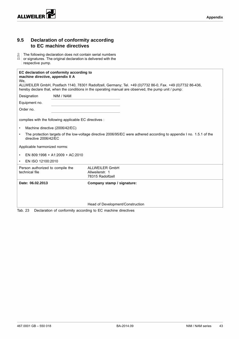
The following declaration does not contain serial numbersor signatures. The original declaration is delivered with therespective pump.
EC declaration of conformity according tomachine directive, appendix II AWe,ALLWEILER GmbH, Postfach 1140, 78301 Radolfzell, Germany; Tel. +49 (0)7732 86-0, Fax. +49 (0)7732 86-436,hereby declare that, when the conditions in the operating manual are observed, the pump unit / pump:
Designation NIM / NAM
Equipment no.
Order no.
complies with the following applicable EC directives :
• Machine directive (2006/42/EC)
• The protection targets of the low-voltage directive 2006/95/EC were adhered according to appendix I no. 1.5.1 of thedirective 2006/42/EC
Applicable harmonized norms:
• EN 809:1998 + A1:2009 + AC:2010
• EN ISO 12100:2010
Person authorized to compile thetechnical file
ALLWEILER GmbHAllweilerstr. 178315 Radolfzell
Date: 06.02.2013 Company stamp / signature:
Head of Development/Construction
Tab. 23 Declaration of conformity according to EC machine directives
467.0001 GB – 550 018 BA-2014.09 NIM / NAM series 43
Appendix
44 NIM / NAM series BA-2014.09 467.0001 GB – 550 018