USE ONLY HAYWARD GENUINE REPLACEMENT PARTS Page 2 Powerline Rev. A
WARNING – Disconnect the pump from the main power supply completely before servicing the pump or filter.
WARNING – All electrical connections must be done by a qualified electrician according to local electrical regulations and AS/NZS 3000 Wiring Rules .
WARNING – Be certain the pump is only plugged into a 230 V ± 10% outlet that is supplied through a Residual Current Device (RCD or Safety Switch) with a residual operating current not exceeding 30mA or supplied by an isolating transformer.
WARNING objects away from openings and moving parts.
WARNING – Use a motor bonding lug to connect motor with other bonded parts using the appropriate size conductor as required by electrical codes.
WARNING – This Product should be installed and serviced only by a qualified professional.
WARNING – Read and follow all instructions in this owner’s manual and on the equipment. Failure to follow instructions can cause serious injury or death. This document should be given to the owner of the swimming pool and must be kept by the owner in a safe place.
WARNING – The appliance is not intended for use by persons (including children) with reduced physical, sensory or mental capabilities, or lack of experience and knowledge, unless they have been given supervision or instruction concerning use of the appliance in a safe way and understand the hazards involved.
WARNING – Cleaning and user maintenance shall not be made by children without supervision.
WARNING – The pump is intended for continuous operation at Maximum Water temperature 35°C.
WARNING – Use Only Genuine Hayward Replacement Parts.
WARNING – If the supply cord is damaged it must be replaced by the manufacturer, service agent, or similarly qualified persons in order to avoid a hazard.
WARNING – Do not operate the swimming pool pump if the power cord or the housing of the motor connection box is damaged. This can cause an electric shock. A damaged power cord or motor connection box must be replaced by a service agent or a similarly qualified person immediately in order to avoid a hazard.
WARNING – This pool motor is NOT equipped with a Safety Vacuum Release System (SVRS). SVRS helps prevent drowning due to body entrapment on underwater drains. In some pool configuration, if a person’s body covers the drain, the person can be trapped by suction. Depending on your pool configuration, a SVRS may be required to meet local requirements.
WARNING: Electrical Hazard. Failure to followinstructions can result in serious injury or death.
FOR USE WITH SWIMMING POOLS
WARNING – This pump is equipped with Automatic Thermal Overload Protection. The motor will automatically shut- off under normal conditions, befor heat damage build-up, due to improper operating condition, can occur. The motor willautomatically restart when a safe heat level is reached.
USE ONLY HAYWARD GENUINE REPLACEMENT PARTS Page 3 Powerline Rev. A
GENERAL
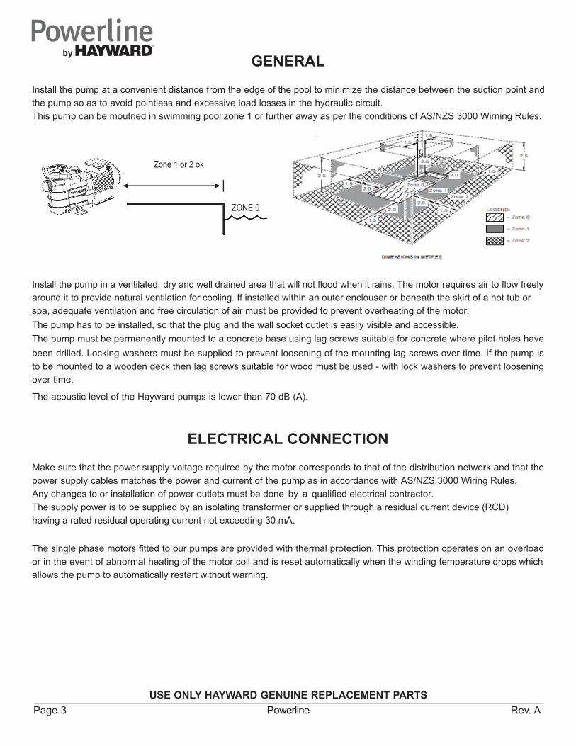
Install the pump at a convenient distance from the edge of the pool to minimize the distance between the suction point andthe pump so as to avoid pointless and excessive load losses in the hydraulic circuit.This pump can be moutned in swimming pool zone 1 or further away as per the conditions of AS/NZS 3000 Wirning Rules.
Zone 1 or 2 ok
ZONE 0
Install the pump in a ventilated, dry and well drained area that will not flood when it rains. The motor requires air to flow freely around it to provide natural ventilation for cooling. If installed within an outer enclouser or beneath the skirt of a hot tub orspa, adequate ventilation and free circulation of air must be provided to prevent overheating of the motor.The pump has to be installed, so that the plug and the wall socket outlet is easily visible and accessible.The pump must be permanently mounted to a concrete base using lag screws suitable for concrete where pilot holes have been drilled. Locking washers must be supplied to prevent loosening of the mounting lag screws over time. If the pump is to be mounted to a wooden deck then lag screws suitable for wood must be used - with lock washers to prevent loosening over time.
The acoustic level of the Hayward pumps is lower than 70 dB (A).
The single phase motors fitted to our pumps are provided with thermal protection. This protection operates on an overload or in the event of abnormal heating of the motor coil and is reset automatically when the winding temperature drops which allows the pump to automatically restart without warning.
ELECTRICAL CONNECTION
Make sure that the power supply voltage required by the motor corresponds to that of the distribution network and that the power supply cables matches the power and current of the pump as in accordance with AS/NZS 3000 Wiring Rules.Any changes to or installation of power outlets must be done by a qualified electrical contractor. The supply power is to be supplied by an isolating transformer or supplied through a residual current device (RCD)having a rated residual operating current not exceeding 30 mA.
USE ONLY HAYWARD GENUINE REPLACEMENT PARTS Page 4 Powerline Rev. A
STARTING AND PRIMING INSTRUCTIONSFill strainer housing with water to suction pipe level. Never operate the pump without water. Water acts as a coolant and lubricant for the mechanical shaft seal.Open all suction and discharge valves, as well as air bleed (if available) on filter. (The air that is to be displaced from the suction line must have someplace to go).Turn on power and allow a reasonable time for priming. Five minutes is not unreasonable. (Priming time depends on suction lift and horizontal length of suction piping). If pump will not start, or will not prime, see TROUBLE SHOOTING GUIDE.
MAINTENANCE1. Clean strainer basket regularly. Do not strike basket to clean. Inspect strainer cover gasket regularly and replace as
necessary.2. Hayward pumps have self-lubricating motor bearings and shaft seals. No lubrication is necessary 3. Keep motor clean. Insure air vents are free from obstruction.4. Occasionally, shaft seals become damaged or worn and must be replaced.5. Except for cleaning activities, any repairing, servicing and maintenance has to be performed by a Hayward authorized
service agent or a similarly qualified person.
STORAGE1. Drain pump by removing drain plug(s) and store in strainer basket.2. Disconnect electrical wires and pipe connections, and store pump in a dry, well-ventilated room. Or, as a minimum
precaution: Disconnect electrical wires. Remove four bolts holding bracket and motor assembly to Strainer/Housing and store assembly in a dry, well-ventilated room. Protect remaining Strainer/Housing assembly from the elements by covering.
NOTE: Before Re-Activating pump, thoroughly clean and remove scale, dirt, etc.
TROUBLE SHOOTING GUIDEA) Motor won’t start - Check for :1. Power cord is plugged into power outlet, open switches or relays, blown circuit breakers or fuses.2. Manually check rotation of motor shaft for free movement and lack of obstruction.
B) Motor cuts out - Check for : (Recommend contacting service agent or similarly qualified person)1. Damaged power cord, plug, or power outlet.2. Low voltage at motor (frequently caused by undersized wiring).3 Binding and overload. (Amperage reading.).NOTE Your pump motor is equipped with Automatic Thermal Overload Protection. The motor will automatically shut-off,
under conditions before heat damage build-up, due to an improper operating condition, can occur. The motor will auto-restart when safe heat level is reached.
C) Motor hums, but does not start - Check for :1. Open capacitor or debris jammed in the impeller (Contact service agent or similarly qualified person).
D) Pump won’t prime :1. Make sure pump strainer/housing is filled with water, and that cover gasket is clean and properly seated. Tighten hand
nuts.2. Make sure all suction and discharge valves are open and unobstructed, and that pool water level is above all suction
openings.
USE ONLY HAYWARD GENUINE REPLACEMENT PARTS Page 5 Powerline Rev. A
3. Block off suction as close to pump as possible and determine if pump will develop a vacuum. a) If pump does not develop vacuum, and pump has sufficient “priming water”: 1. Tighten all bolts and fittings on suction side. 2. Check voltage to make sure pump is up to speed. 3. Open pump and check for clogging or obstruction. 4. Remove and replace shaft seal. b) If pump develops a vacuum, check for blocked suction line or strainer, or air leak in suction piping.
E) Low flow - Generally, Check for :1. Clogged or restricted strainer or suction line; undersized pool piping.2. Plugged or restricted discharge line of filter (high discharge gauge reading).3. Air leak in suction (bubbles issuing from return fittings).4. Pump operating under speed (low voltage).5. Plugged or restricted impeller.
F) Noisy pump - Check for 1. Air leak in suction causing rumbling in pump. 2. Cavitation due to restricted or undersized suction line and unrestricted discharge lines. Correct suction condition or throttle discharge lines, if practical. 3. Vibration due to improper mounting, etc. 4. Foreign matter in pump housing. 5. Motor bearings made unserviceable by wear, rust, or continual overheating.
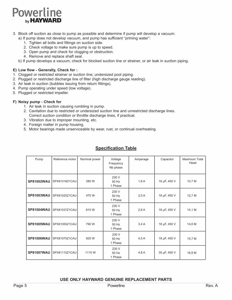
Pump Reference motor Nominal power VoltageFrequencyNb phase