Centro-Matic ® Automated Lubrication Systems Introduction 2 Air-Operated Actuated automatically by compressed air at various pre-determined intervals. An air-operated pump delivers lubricant to the injectors. When all injectors have cycled, the pump shuts off automatically and vents lubricant pressure. Available with automatic, manual or mechanical controls. Electric Used where compressed air is not available, or electrical operation is preferred. Totally enclosed motor supplies the power requirements of the pumping mechanism. Time control is adjustable to provide predetermined frequency of lubrication. Manual Designed for smaller, individual machines, manual systems provide a low-cost, efficient method of distribut- ing lubricant to the injectors. Cycling a complete bank of injectors takes only a few seconds. In manually- operated systems, the lubricant pump is hand- operated and the machine operator performs the lubrication intervals. Hydraulic A complete hydraulically- powered pumping unit for centralized lubrication of individual machines. Usually installed on machinery such as coal mining and earth moving equipment which utilize a hydraulic pressure system. The frequency of the lubrication cycle can be set manually or by mechani- cal or automatic controls. Lincoln Industrial Centro-Matic ® systems and components are made to match your application. Systems can service one machine, different zones on one machine, or even several separate machines. Regardless of the application, the principle of centralized lubrication remains the same: a central pump station automatically delivers lubricant through a single supply line to the injectors. Each injector serves only one lubrication point and may be accurately adjusted to deliver the precise amount of grease or oil required. Centro-Matic systems give you multiple advantages over other designs. Simplicity Systems are easy to understand, install and maintain. You realize savings right from the start because one lubricant supply line means lower installation costs. Powerful Pumping Unit Centro-Matic systems dispense either grease or oil in measured quantities, unaffected by normal temperature or viscosity changes. For large systems, Lincoln Industrial’s single-line design and powerful pumps mean injectors can be located long distances from original refinery containers or bulk lubricant tanks. External Adjustment Lubricant injectors are externally adjustable without special tools so each bearing can receive the correct amount of lubricant. No under- or over-lubrication at individual points. Visual Indicators Each injector incorporates an indicator pin that gives visual confirmation the injector is operating correctly. When necessary, troubleshooting is the simple process of checking indicator pins. Ease of Service When injectors finally need service, the job is quick and easy. No need to remove supply line connections or disturb adjacent injectors. Replacement can usually be done between lubrication cycles, so there’s almost no lubricant loss or downtime. Parts and Service You’re never far from a Lincoln Industrial authorized distributor. Qualified distributors offer design engineering, startup help, and training for your personnel in the use and maintenance of Centro-Matic systems. They’ll back you up with parts and service for years after the sale.
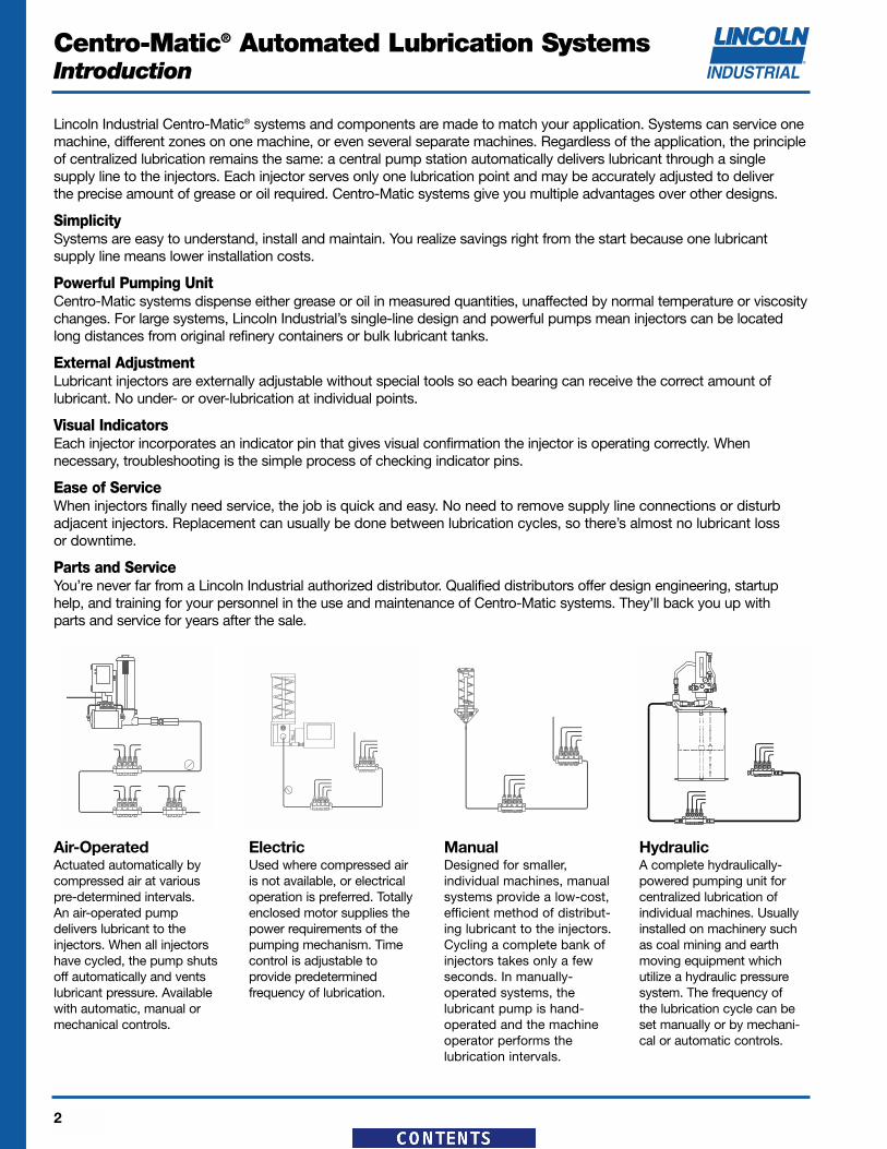
Air-OperatedActuated automatically bycompressed air at variouspre-determined intervals. An air-operated pump delivers lubricant to the injectors. When all injectorshave cycled, the pump shutsoff automatically and ventslubricant pressure. Availablewith automatic, manual ormechanical controls.
ElectricUsed where compressed airis not available, or electricaloperation is preferred. Totallyenclosed motor supplies thepower requirements of thepumping mechanism. Timecontrol is adjustable to provide predetermined frequency of lubrication.
ManualDesigned for smaller, individual machines, manual systems provide a low-cost,efficient method of distribut-ing lubricant to the injectors.Cycling a complete bank ofinjectors takes only a fewseconds. In manually-operated systems, the lubricant pump is hand-operated and the machineoperator performs the lubrication intervals.
HydraulicA complete hydraulically-powered pumping unit forcentralized lubrication of individual machines. Usuallyinstalled on machinery suchas coal mining and earthmoving equipment which utilize a hydraulic pressuresystem. The frequency of the lubrication cycle can beset manually or by mechani-cal or automatic controls.
Lincoln Industrial Centro-Matic® systems and components are made to match your application. Systems can service onemachine, different zones on one machine, or even several separate machines. Regardless of the application, the principleof centralized lubrication remains the same: a central pump station automatically delivers lubricant through a single supply line to the injectors. Each injector serves only one lubrication point and may be accurately adjusted to deliver the precise amount of grease or oil required. Centro-Matic systems give you multiple advantages over other designs.
SimplicitySystems are easy to understand, install and maintain. You realize savings right from the start because one lubricant supply line means lower installation costs.
Powerful Pumping UnitCentro-Matic systems dispense either grease or oil in measured quantities, unaffected by normal temperature or viscositychanges. For large systems, Lincoln Industrial’s single-line design and powerful pumps mean injectors can be locatedlong distances from original refinery containers or bulk lubricant tanks.
External AdjustmentLubricant injectors are externally adjustable without special tools so each bearing can receive the correct amount of lubricant. No under- or over-lubrication at individual points.
Visual IndicatorsEach injector incorporates an indicator pin that gives visual confirmation the injector is operating correctly. When necessary, troubleshooting is the simple process of checking indicator pins.
Ease of ServiceWhen injectors finally need service, the job is quick and easy. No need to remove supply line connections or disturbadjacent injectors. Replacement can usually be done between lubrication cycles, so there’s almost no lubricant loss or downtime.
Parts and ServiceYou’re never far from a Lincoln Industrial authorized distributor. Qualified distributors offer design engineering, startuphelp, and training for your personnel in the use and maintenance of Centro-Matic systems. They’ll back you up with parts and service for years after the sale.
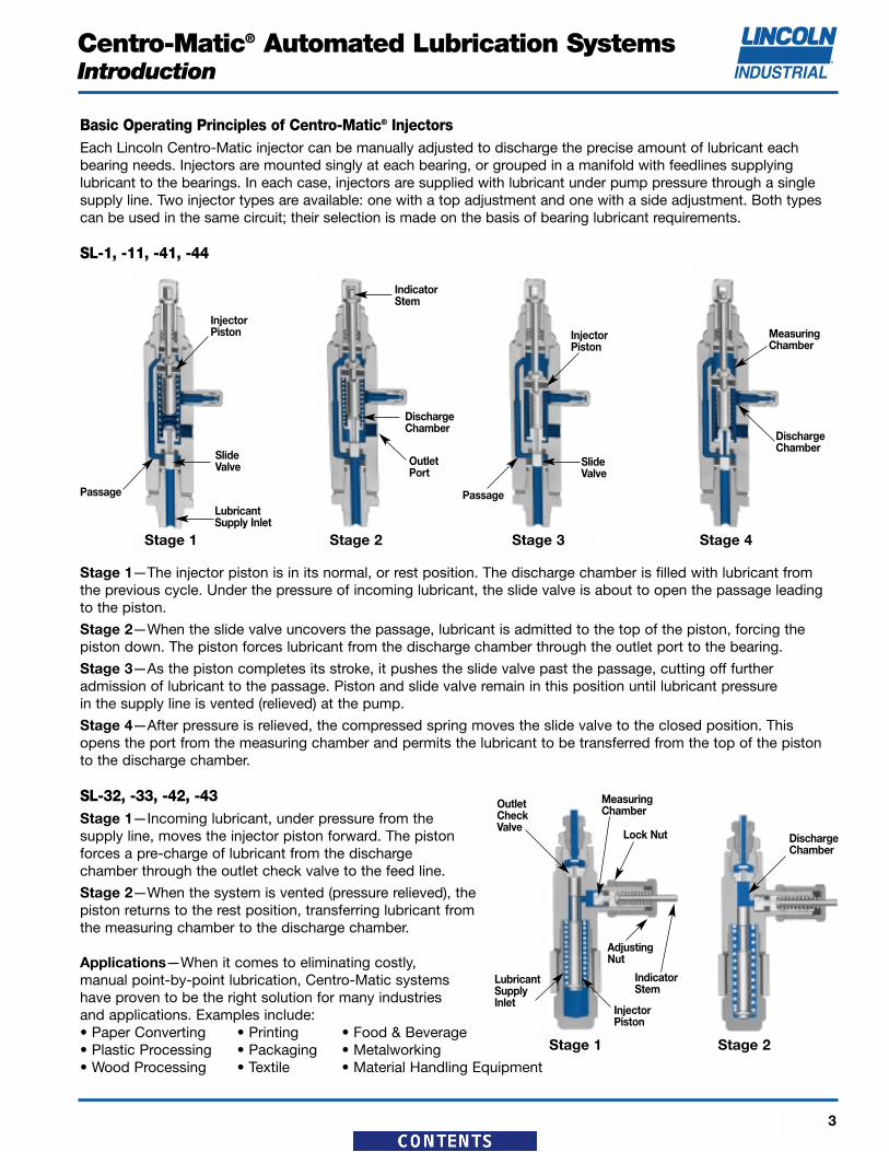
Basic Operating Principles of Centro-Matic® InjectorsEach Lincoln Centro-Matic injector can be manually adjusted to discharge the precise amount of lubricant eachbearing needs. Injectors are mounted singly at each bearing, or grouped in a manifold with feedlines supplying lubricant to the bearings. In each case, injectors are supplied with lubricant under pump pressure through a singlesupply line. Two injector types are available: one with a top adjustment and one with a side adjustment. Both typescan be used in the same circuit; their selection is made on the basis of bearing lubricant requirements.
SL-1, -11, -41, -44
Stage 1—The injector piston is in its normal, or rest position. The discharge chamber is filled with lubricant fromthe previous cycle. Under the pressure of incoming lubricant, the slide valve is about to open the passage leadingto the piston.
Stage 2—When the slide valve uncovers the passage, lubricant is admitted to the top of the piston, forcing the piston down. The piston forces lubricant from the discharge chamber through the outlet port to the bearing.
Stage 3—As the piston completes its stroke, it pushes the slide valve past the passage, cutting off further admission of lubricant to the passage. Piston and slide valve remain in this position until lubricant pressure in the supply line is vented (relieved) at the pump.
Stage 4—After pressure is relieved, the compressed spring moves the slide valve to the closed position. Thisopens the port from the measuring chamber and permits the lubricant to be transferred from the top of the pistonto the discharge chamber.
SL-32, -33, -42, -43Stage 1—Incoming lubricant, under pressure from the supply line, moves the injector piston forward. The pistonforces a pre-charge of lubricant from the discharge chamber through the outlet check valve to the feed line.
Stage 2—When the system is vented (pressure relieved), the piston returns to the rest position, transferring lubricant fromthe measuring chamber to the discharge chamber.
Applications—When it comes to eliminating costly, manual point-by-point lubrication, Centro-Matic systemshave proven to be the right solution for many industries and applications. Examples include:• Paper Converting • Printing • Food & Beverage• Plastic Processing • Packaging • Metalworking• Wood Processing • Textile • Material Handling Equipment
Notes:1. Injectors, except replacement injectors for manifold, include compression nut and ferrule for tubing — ¹⁄₈" O.D. as standard.
Other outlet connectors for feed line optional.2. Injectors with manifolds include two mounting clips and screws.3. Injectors have Nitrile packings (200°F max. / 93°C). Check packing compatibility with synthetic lubricants.
Specifications:
SeriesOutput Operating Pressure
Min Max Min Max Typical Vent
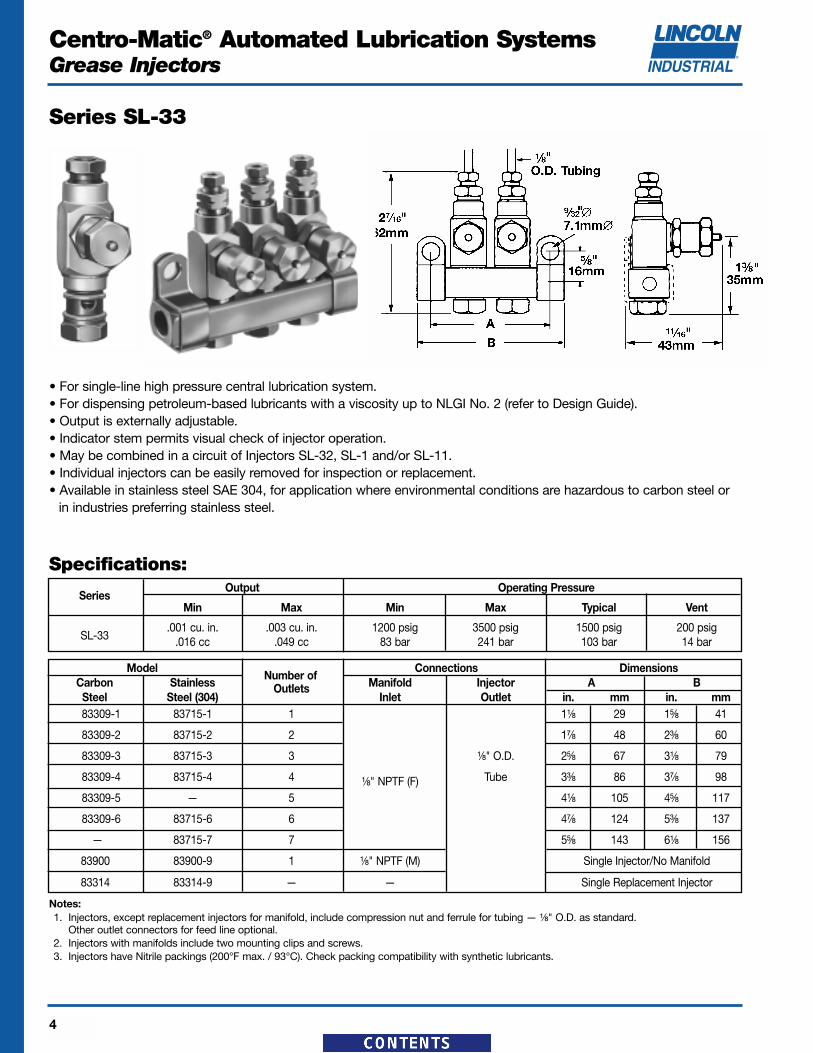
SL-33.001 cu. in. .003 cu. in. 1200 psig 3500 psig 1500 psig 200 psig
.016 cc .049 cc 83 bar 241 bar 103 bar 14 bar
ModelNumber of
Connections DimensionsCarbon Stainless Outlets Manifold Injector A BSteel Steel (304) Inlet Outlet in. mm in. mm83309-1 83715-1 1 1¹⁄₈ 29 1⁵⁄₈ 41
83900 83900-9 1 ¹⁄₈" NPTF (M) Single Injector/No Manifold
83314 83314-9 — — Single Replacement Injector
Series SL-33
• For single-line high pressure central lubrication system.• For dispensing petroleum-based lubricants with a viscosity up to NLGI No. 2 (refer to Design Guide).• Output is externally adjustable.• Indicator stem permits visual check of injector operation.• May be combined in a circuit of Injectors SL-32, SL-1 and/or SL-11.• Individual injectors can be easily removed for inspection or replacement.• Available in stainless steel SAE 304, for application where environmental conditions are hazardous to carbon steel or
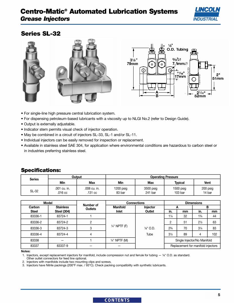
• For single-line high pressure central lubrication system.• For dispensing petroleum-based lubricants with a viscosity up to NLGI No.2 (refer to Design Guide).• Output is externally adjustable.• Indicator stem permits visual check of injector operation.• May be combined in a circuit of injectors SL-33, SL-1 and/or SL-11.• Individual injectors can be easily removed for inspection or replacement.• Available in stainless steel SAE 304, for application where environmental conditions are hazardous to carbon steel or
in industries preferring stainless steel.
Notes:1. Injectors, except replacement injectors for manifold, include compression nut and ferrule for tubing — ¹⁄₈" O.D. as standard.
Other outlet connectors for feed line optional.2. Injectors with manifolds include two mounting clips and screws.3. Injectors have Nitrile packings (200°F max. / 93°C). Check packing compatibility with synthetic lubricants.
Specifications:
SeriesOutput Operating Pressure
Min Max Min Max Typical Vent
SL-32.001 cu. in. .008 cu. in. 1200 psig 3500 psig 1500 psig 200 psig
.016 cc .131 cc 83 bar 241 bar 103 bar 14 bar
ModelNumber of
Connections DimensionsCarbon Stainless Outlets Manifold Injector A BSteel Steel (304) Inlet Outlet in. mm in. mm83336-1 83724-1 1 1¹⁄₄ 32 1³⁄₄ 44
83336-2 83724-2 2¹⁄₄" NPTF (F)
2 51 2¹⁄₂ 63
83336-3 83724-3 3 ¹⁄₈" O.D. 2³⁄₄ 70 3¹⁄₄ 83
83336-4 83724-4 4 Tube 3¹⁄₂ 89 4 102
83338 — 1 ¹⁄₄" NPTF (M) Single Injector/No Manifold
83337 83337-9 — — Replacement for manifold injectors
81713A 84776* Injector 85451 Replacement for manifolded injectors
* For complete assembly, you must order stainless steel manifold and corresponding quantity of Model #84776 Injectors separately.** For use with aggressive lubricants that attack Viton seals at high temperatures.
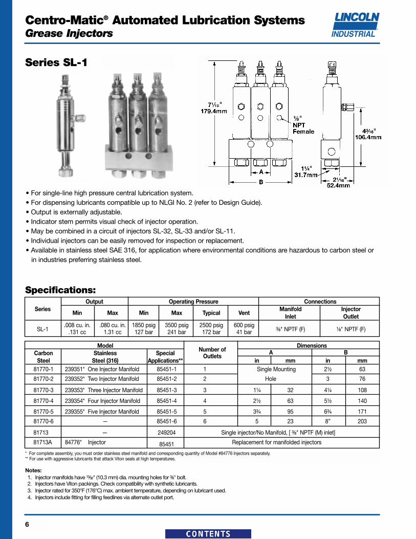
Series SL-1
• For single-line high pressure central lubrication system.• For dispensing lubricants compatible up to NLGI No. 2 (refer to Design Guide).• Output is externally adjustable.• Indicator stem permits visual check of injector operation.• May be combined in a circuit of injectors SL-32, SL-33 and/or SL-11.• Individual injectors can be easily removed for inspection or replacement.• Available in stainless steel SAE 316, for application where environmental conditions are hazardous to carbon steel or
in industries preferring stainless steel.
Specifications:
Notes:1. Injector manifolds have ¹³⁄₃₂" (10.3 mm) dia. mounting holes for ³⁄₈" bolt.2. Injectors have Viton packings. Check compatibility with synthetic lubricants.3. Injector rated for 350°F (176°C) max. ambient temperature, depending on lubricant used.4. Injectors include fitting for filling feedlines via alternate outlet port.
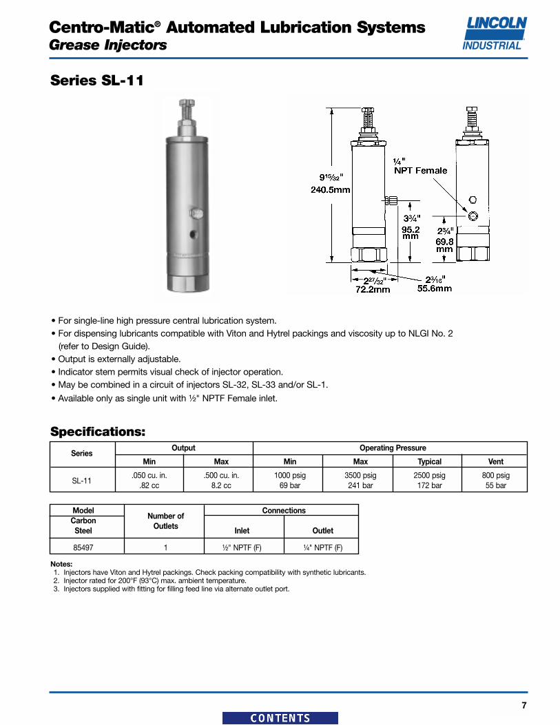
• For single-line high pressure central lubrication system.• For dispensing lubricants compatible with Viton and Hytrel packings and viscosity up to NLGI No. 2
(refer to Design Guide).• Output is externally adjustable.• Indicator stem permits visual check of injector operation.• May be combined in a circuit of injectors SL-32, SL-33 and/or SL-1.
• Available only as single unit with ¹⁄₂" NPTF Female inlet.
Specifications:
SeriesOutput Operating Pressure
Min Max Min Max Typical Vent
SL-11.050 cu. in. .500 cu. in. 1000 psig 3500 psig 2500 psig 800 psig
.82 cc 8.2 cc 69 bar 241 bar 172 bar 55 bar
ModelNumber of
ConnectionsCarbon
OutletsSteel Inlet Outlet
85497 1 ¹⁄₂" NPTF (F) ¹⁄₄" NPTF (F)
Notes:1. Injectors have Viton and Hytrel packings. Check packing compatibility with synthetic lubricants.2. Injector rated for 200°F (93°C) max. ambient temperature.3. Injectors supplied with fitting for filling feed line via alternate outlet port.
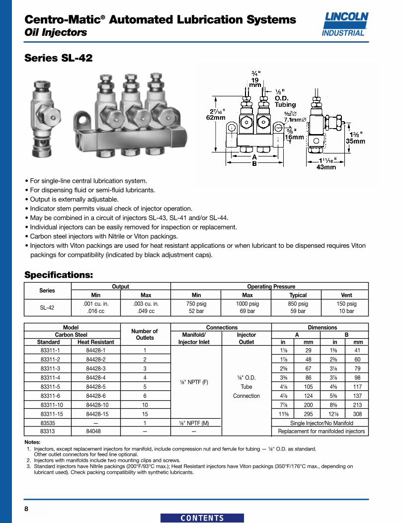
• For single-line central lubrication system.• For dispensing fluid or semi-fluid lubricants.• Output is externally adjustable.• Indicator stem permits visual check of injector operation.• May be combined in a circuit of injectors SL-43, SL-41 and/or SL-44.• Individual injectors can be easily removed for inspection or replacement.• Carbon steel injectors with Nitrile or Viton packings.• Injectors with Viton packings are used for heat resistant applications or when lubricant to be dispensed requires Viton
packings for compatibility (indicated by black adjustment caps).
Notes:1. Injectors, except replacement injectors for manifold, include compression nut and ferrule for tubing — ¹⁄₈" O.D. as standard.
Other outlet connectors for feed line optional.2. Injectors with manifolds include two mounting clips and screws.3. Standard injectors have Nitrile packings (200°F/93°C max.); Heat Resistant injectors have Viton packings (350°F/176°C max., depending on
lubricant used). Check packing compatibility with synthetic lubricants.
Specifications:
SeriesOutput Operating Pressure
Min Max Min Max Typical Vent
SL-42.001 cu. in. .003 cu. in. 750 psig 1000 psig 850 psig 150 psig
.016 cc .049 cc 52 bar 69 bar 59 bar 10 bar
ModelNumber of
Connections DimensionsCarbon Steel Outlets Manifold/ Injector A B
Standard Heat Resistant Injector Inlet Outlet in mm in mm83311-1 84428-1 1 1¹⁄₈ 29 1⁵⁄₈ 41
83311-2 84428-2 2 1⁷⁄₈ 48 2³⁄₈ 60
83311-3 84428-3 3 2⁵⁄₈ 67 3¹⁄₈ 79
83311-4 84428-4 4¹⁄₈" NPTF (F)
¹⁄₈" O.D. 3³⁄₈ 86 3⁷⁄₈ 98
83311-5 84428-5 5 Tube 4¹⁄₈ 105 4⁵⁄₈ 117
83311-6 84428-6 6 Connection 4⁷⁄₈ 124 5³⁄₈ 137
83311-10 84428-10 10 7⁷⁄₈ 200 8³⁄₈ 213
83311-15 84428-15 15 11⁵⁄₈ 295 12¹⁄₈ 308
83535 — 1 ¹⁄₈" NPTF (M) Single Injector/No Manifold83313 84048 — — Replacement for manifolded injectors
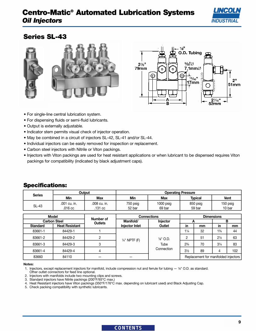
• For single-line central lubrication system.• For dispensing fluids or semi-fluid lubricants.• Output is externally adjustable.• Indicator stem permits visual check of injector operation.• May be combined in a circuit of injectors SL-42, SL-41 and/or SL-44.• Individual injectors can be easily removed for inspection or replacement.• Carbon steel injectors with Nitrile or Viton packings.• Injectors with Viton packings are used for heat resistant applications or when lubricant to be dispensed requires Viton
packings for compatibility (indicated by black adjustment caps).
Notes:1. Injectors, except replacement injectors for manifold, include compression nut and ferrule for tubing — ¹⁄₈" O.D. as standard.
Other outlet connectors for feed line optional.2. Injectors with manifolds include two mounting clips and screws.3. Standard injectors have Nitrile packings (200°F/93°C max.)4. Heat Resistant injectors have Viton packings (350°F/176°C max. depending on lubricant used) and Black Adjusting Cap.5. Check packing compatibility with synthetic lubricants.
Specifications:
SeriesOutput Operating Pressure
Min Max Min Max Typical Vent
SL-43.001 cu. in. .008 cu. in. 750 psig 1000 psig 850 psig 150 psig
.016 cc .131 cc 52 bar 69 bar 59 bar 10 bar
ModelNumber of
Connections DimensionsCarbon Steel Outlets Manifold/ Injector A B
Standard Heat Resistant Injector Inlet Outlet in mm in mm83661-1 84429-1 1 1¹⁄₄ 32 1³⁄₄ 44
Notes:1. Injector manifolds have ¹³⁄₃₂" mounting holes for ³⁄₈" bolt.2. Injectors have Viton packings. Check packing compatibility with synthetic lubricants.3. Injectors rated at 350°F (176°C) maximum ambient temperature, depending on lubricant used.
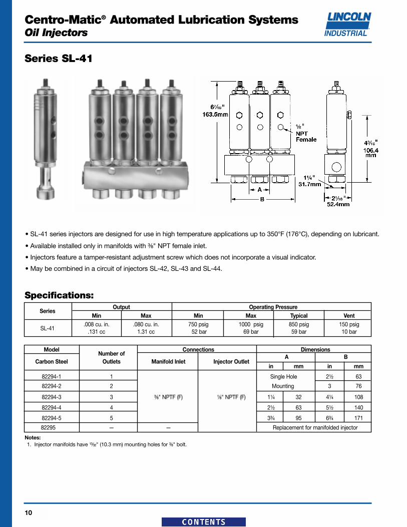
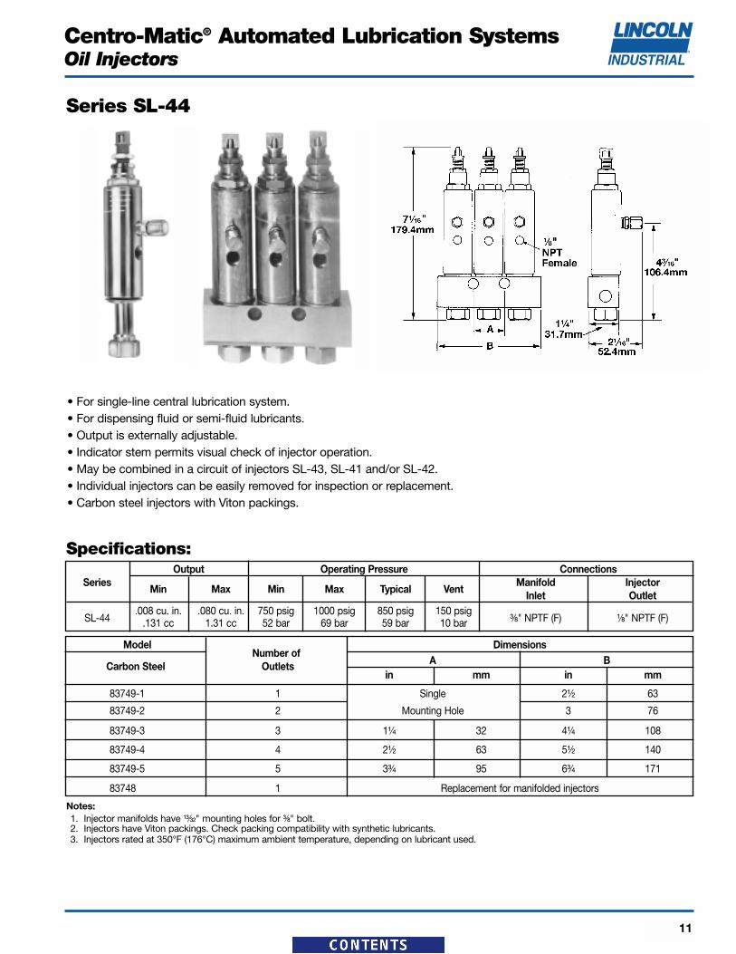
Series SL-44
• For single-line central lubrication system.• For dispensing fluid or semi-fluid lubricants.• Output is externally adjustable.• Indicator stem permits visual check of injector operation.• May be combined in a circuit of injectors SL-43, SL-41 and/or SL-42.• Individual injectors can be easily removed for inspection or replacement.• Carbon steel injectors with Viton packings.
Specifications:
ModelNumber of
Dimensions
Carbon Steel A BOutletsin mm in mm
83749-1 1 Single 2¹⁄₂ 63
83749-2 2 Mounting Hole 3 76
83749-3 3 1¹⁄₄ 32 4¹⁄₄ 108
83749-4 4 2¹⁄₂ 63 5¹⁄₂ 140
83749-5 5 3³⁄₄ 95 6³⁄₄ 171
83748 1 Replacement for manifolded injectors
Output Operating Pressure ConnectionsSeries
Min Max Min Max Typical VentManifold Injector
Inlet Outlet
SL-44.008 cu. in. .080 cu. in. 750 psig 1000 psig 850 psig 150 psig
³⁄₈" NPTF (F) ¹⁄₈" NPTF (F).131 cc 1.31 cc 52 bar 69 bar 59 bar 10 bar
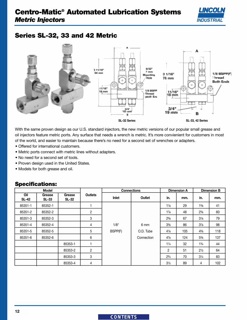
With the same proven design as our U.S. standard injectors, the new metric versions of our popular small grease andoil injectors feature metric ports. Any surface that needs a wrench is metric. It’s more convienient for customers in mostof the world, and easier to maintain because there’s no need for a second set of wrenches or adapters.• Offered for international customers.• Metric ports connect with metric lines without adapters.• No need for a second set of tools.• Proven design used in the United States.• Models for both grease and oil.
Specifications:Model Connections Dimension A Dimension B
Oil Grease Grease OutletsInlet Outlet in. mm. in. mm.SL-42 SL-33 SL-32
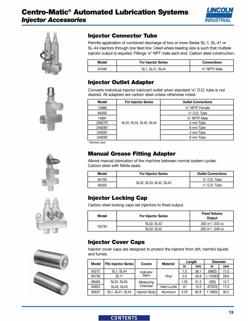
Injector Cover CapsInjector cover caps are designed to protect the injector from dirt, harmful liquidsand fumes.
Injector Connector TubePermits application of combined discharge of two or more Series SL-1, SL-41 or SL-44 injectors through one feed line. Used where bearing size is such that multipleinjector output is required. Fittings ¹⁄₈" NPT male each end. Carbon steel construction.
Model For Injector Series Connections
81646 SL1, SL41, SL44 ¹⁄₈" NPTF Male
Model For Injector Series Outlet Connections
14988 ¹⁄₈" NPTF Female84200 ¹⁄₄" O.D. Tube14991 ¹⁄₈" NPTF Male
249279* SL32, SL33, SL42, SL43 4 mm Tube249280* 6 mm Tube249281 4 mm Tube249282 6 mm Tube
Manual Grease Fitting AdapterAllows manual lubrication of the machine between normal system cycles. Carbon steel with Nitrile seals.
Model For Injector Series Outlet Connections
84195 ¹⁄₈" O.D. Tube
84203SL32, SL33, SL42, SL43
¹⁄₄" O.D. Tube
Injector Locking CapCarbon steel locking caps set injectors to fixed output.
Injector Outlet AdapterConverts individual injector lubricant outlet when standard ¹⁄₈" O.D. tube is notdesired. All adapters are carbon steel unless otherwise noted.
Lubricant flows through Supply Lines between the pump and injectors, then through Feed Lines between the injectorand the bearing. Tubing and/or pipe sizes are determined after considering both the length of the line and the specificlubricant intended for use in the system.
Your Lincoln Industrial representative can assist you in the proper selection of supply and feed line material to optimizeyour application.
Listed below is a simplified outline of the installation components offered. For a complete listing of products, pleaserefer to the Installation Components catalog.
TUBING
Hydraulic, Steel, Stainless Steeland Nylon
Single and Multiple TubeClamps
Heavy Duty, Standard Duty,Threaded Sleeve and Snap-OnCoupler Tube Fittings
Quicklinc® Tubing Adapter
Zerk-Lock™ Grease FittingAdapters
Non-Metallic
PIPING
Seamless
Continuous Welded
Forged Fittings
Malleable Iron Fittings
316 Stainless Steel Pipe and Fittings
Stainless Steel Fittings
Galvanized Pipe, Threaded Plugand Fittings
ACCESSORIES
Supply, Feed and Bulk Feed Line Hose
Air Hose
Kits for Hose Repair
Heavy-Duty Air Line QuickDisconnects
AIR CONTROL AND ACCESSORIES
Manual Shut-Off Valves
Pressure Gauges
Lubricant Filters and Strainers
AIRCARE™ AIR PREPARATION SYSTEMS
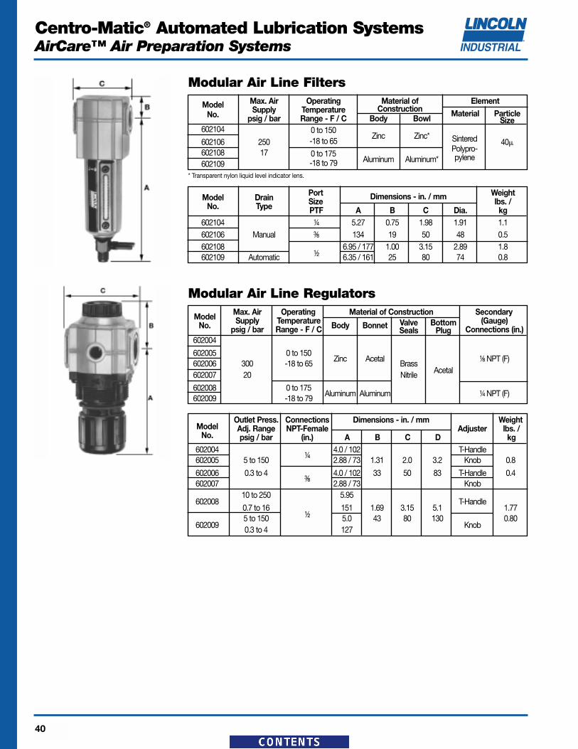
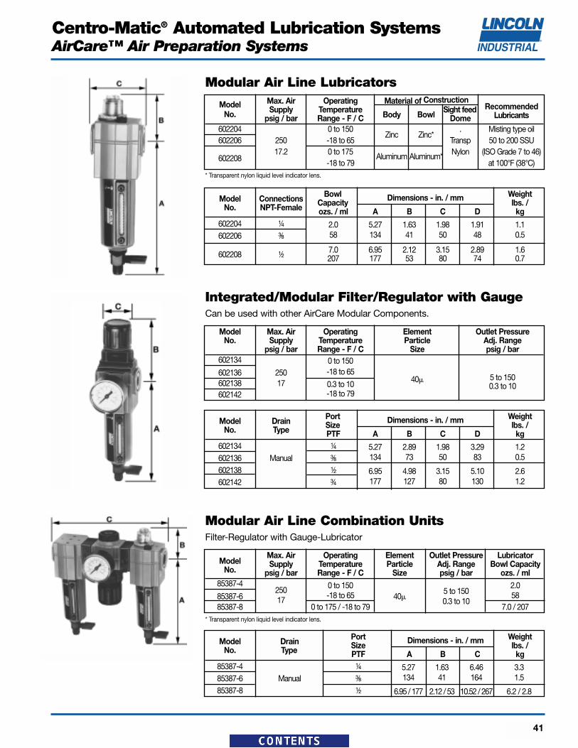
Modular Air Line Filters,Regulators and Lubricators
Integrated/ModularFilter/Regulator with Gauge
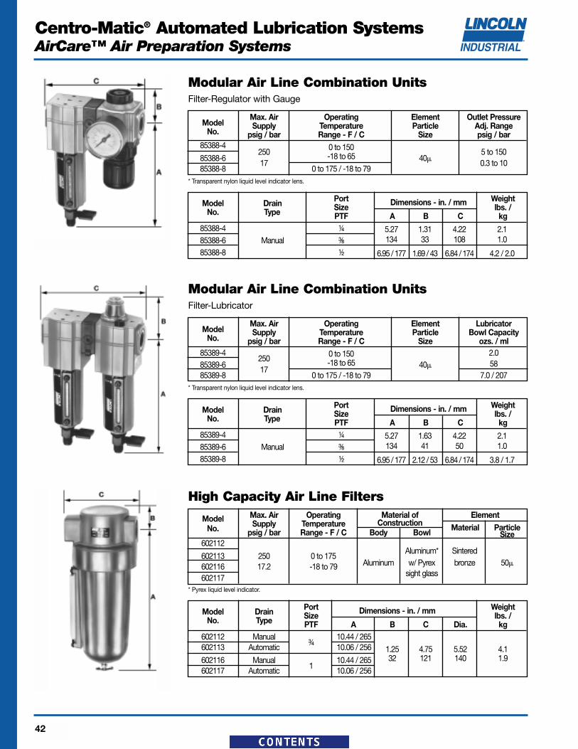
Modular Air Line Combination Units
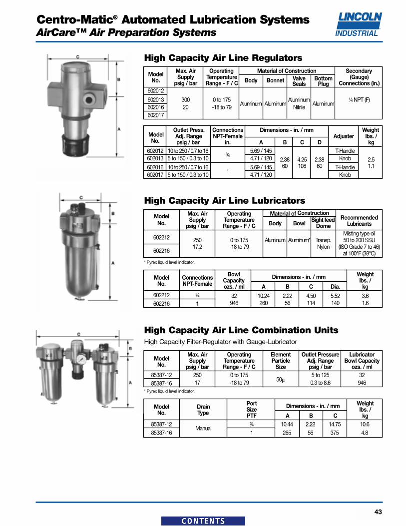
High Capacity Air Line Filters,Regulators and Lubricators
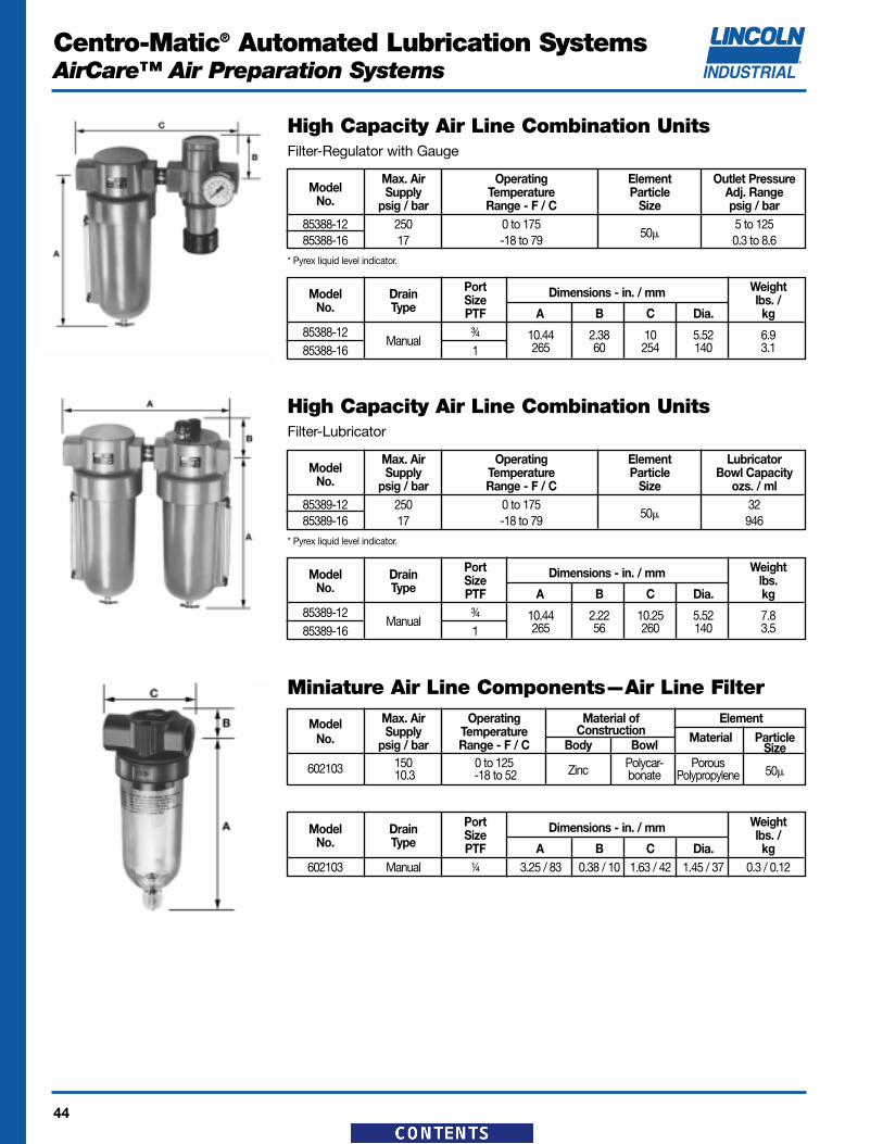
High Capacity Air LineCombination Units
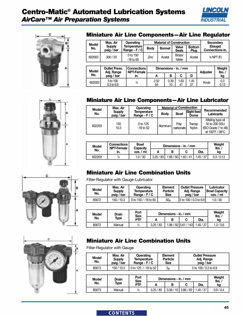
Miniature Air LineComponents—Air Line Filter,Regulator and Lubricator
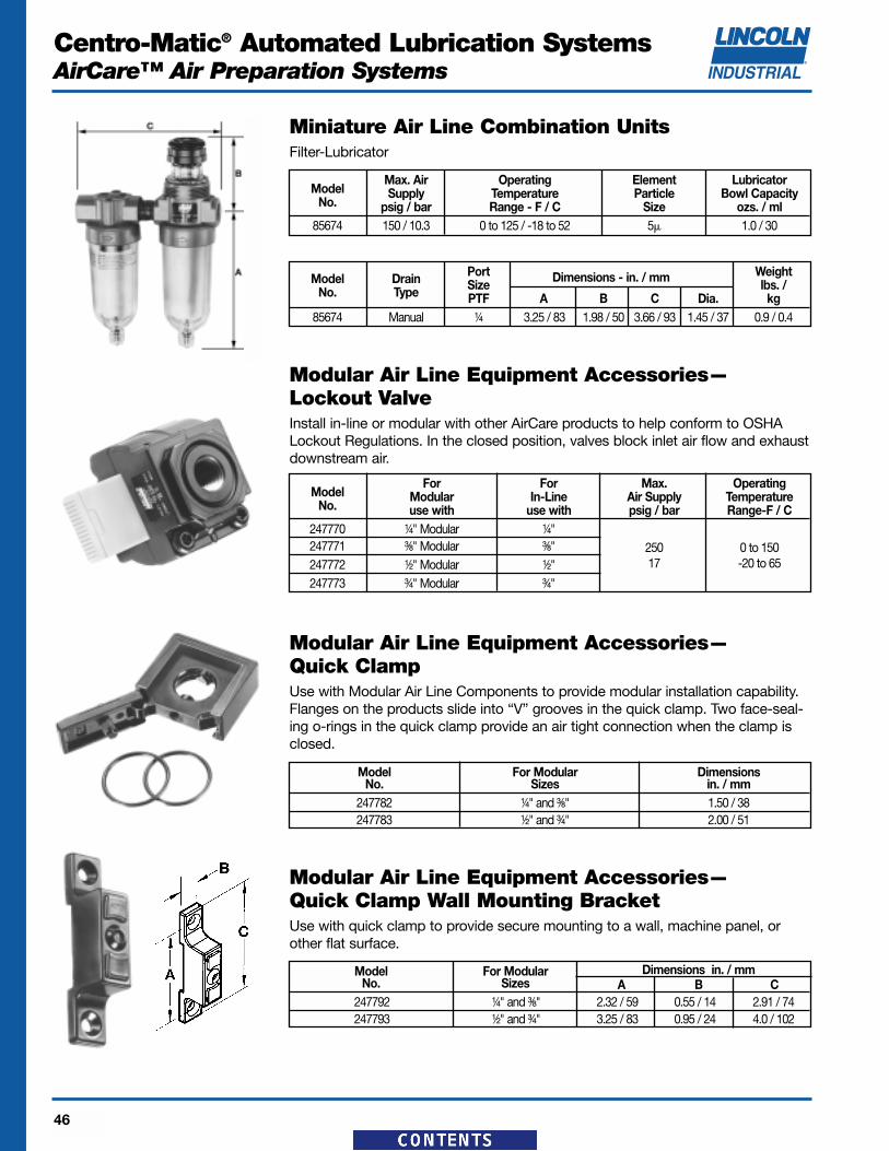
Miniature Air Line Combination Units
Modular Air Line EquipmentAccessories:Lockout Valve, Quick Clamp,Quick Clamp Wall MountingBracket, Porting Block, QuickMount Pipe Adapters, ManifoldBlock, Pressure Switch, PanelNut, Wall Mount Bracket,Tamper Resistant Cover & Seal Wire
Air Line EquipmentAccessories: Wall Mount Bracket, HighCapacity; Mounting Bracketand Nut, Miniature; PressureGauges
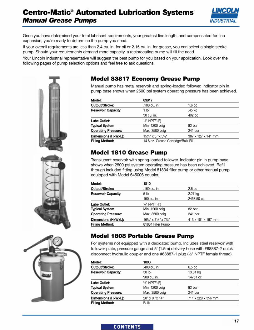
Model 83817 Economy Grease PumpManual pump has metal reservoir and spring-loaded follower. Indicator pin inpump base shows when 2500 psi system operating pressure has been achieved.
Model: 83817Output/Stroke: .100 cu. in. 1.6 ccReservoir Capacity: 1 lb. .45 kg
30 cu. in. 492 cc
Lube Outlet: ¹⁄₈" NPTF (F)Typical System Min. 1200 psig 82 barOperating Pressure: Max. 3500 psig 241 bar
Dimensions (HxWxL): 15¹⁄₄" x 5 "x 5⁵⁄₈" 387 x 127 x 141 mmFilling Method: 14.6 oz. Grease Cartridge/Bulk Fill
Model 1808 Portable Grease PumpFor systems not equipped with a dedicated pump. Includes steel reservoir withfollower plate, pressure gauge and 5' (1.5m) delivery hose with #68887-2 quickdisconnect hydraulic coupler and one #68887-1 plug (¹⁄₂" NPTF female thread).
Model: 1808Output/Stroke: .400 cu. in. 6.5 ccReservoir Capacity: 30 lb. 13.61 kg
900 cu. in. 14751 cc
Lube Outlet: ³⁄₈" NPTF (F)Typical System Min. 1200 psig 82 barOperating Pressure: Max. 3500 psig 241 bar
Dimensions (HxWxL): 28" x 9 "x 14" 711 x 229 x 356 mmFilling Method: Bulk
Model: 1810Output/Stroke: .160 cu. in. 2.6 ccReservoir Capacity: 5 lb. 2.27 kg
150 cu. in. 2458.50 cc
Lube Outlet: ¹⁄₄" NPTF (F)Typical System Min. 1200 psig 82 barOperating Pressure: Max. 3500 psig 241 bar
Dimensions (HxWxL): 16¹⁄₄" x 7¹⁄₈ "x 7³⁄₄" 413 x 181 x 197 mmFilling Method: 81834 Filler Pump
Model 1810 Grease PumpTranslucent reservoir with spring-loaded follower. Indicator pin in pump baseshows when 2500 psi system operating pressure has been achieved. Refillthrough included fitting using Model 81834 filler pump or other manual pumpequipped with Model 645006 coupler.
Once you have determined your total lubricant requirements, your greatest line length, and compensated for line expansion, you’re ready to determine the pump you need.
If your overall requirements are less than 2.4 cu. in. for oil or 2.15 cu. in. for grease, you can select a single strokepump. Should your requirements demand more capacity, a reciprocating pump will fill the need.
Your Lincoln Industrial representative will suggest the best pump for you based on your application. Look over the following pages of pump selection options and feel free to ask questions.
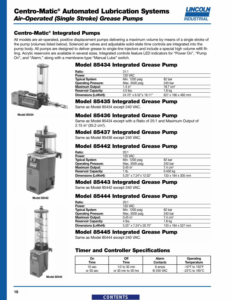
Model 85434 Integrated Grease PumpRatio: 31:1Power: 120 VACTypical System Min. 1200 psig 82 barOperating Pressure: Max. 3500 psig 240 barMaximum Output: 1.4 in3 18.7 cm3
Reservoir Capacity: 4.5 lbs. 1.8 kgDimensions (LxWxH): 24.70" x 6.52"x 18.11" 627 x 166 x 460 mm
Model 85435 Integrated Grease PumpSame as Model 85434 except 240 VAC.
Model 85436 Integrated Grease PumpSame as Model 85434 except with a Ratio of 25:1 and Maximum Output of 2.15 in3 (35.2 cm3).
Model 85437 Integrated Grease PumpSame as Model 85436 except 240 VAC.
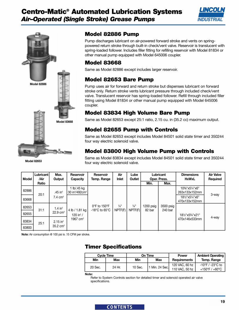
Model 85442 Integrated Grease PumpRatio: 20:1Power: 120 VACTypical System Min. 1200 psig 82 barOperating Pressure: Max. 3500 psig 240 barMaximum Output: 0.45 in3 7.4 cm3
Reservoir Capacity: 1 lb. 0.450 kgDimensions (LxWxH): 5.25" x 7.24"x 12.02" 133 x 184 x 305 mm
Model 85443 Integrated Grease PumpSame as Model 85442 except 240 VAC.
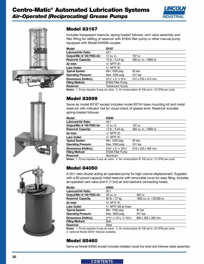
Model 85444 Integrated Grease PumpRatio: 20:1Power: 120 VACTypical System Min. 1200 psig 82 barOperating Pressure: Max. 3500 psig 240 barMaximum Output: 0.45 in3 7.4 cm3
Reservoir Capacity: 4 lbs. 1.8 kgDimensions (LxWxH): 5.25" x 7.24"x 20.75" 133 x 184 x 527 mm
Model 85445 Integrated Grease PumpSame as Model 85444 except 240 VAC.
Centro-Matic® Integrated PumpsAll models are air-operated, positive displacement pumps delivering a maximum volume by means of a single stroke ofthe pump (volumes listed below). Solenoid air valves and adjustable solid-state time controls are integrated into thepump body. All pumps are designed to deliver grease to single-line injectors and include a special high volume refill fit-ting. Acrylic reservoirs are available in several sizes. Integrated controls feature LED indicators for “Power On”, “PumpOn”, and “Alarm,” along with a membrane-type “Manual Lube” switch.
Timer and Controller SpecificationsOn Off Alarm Operating
Time Time Contacts Temperature10 sec 1/2 to 30 min 8 amps -10°F to 150°F
or 30 sec or 30 min to 30 hrs @ 250 VAC -23°C to 165°C
Note:Refer to System Controls section for detailed timer and solenoid operated air valve specifications.
Timer Specifications
Cycle Time On Time Power Ambient OperatingMin Max Min Max Requirements Temp. Range
20 Sec. 24 Hr. 10 Sec. 1 Min. 24 Sec.120 VAC, 60 hz -10°F / -23°C to110 VAC, 50 hz +150°F / +60°C
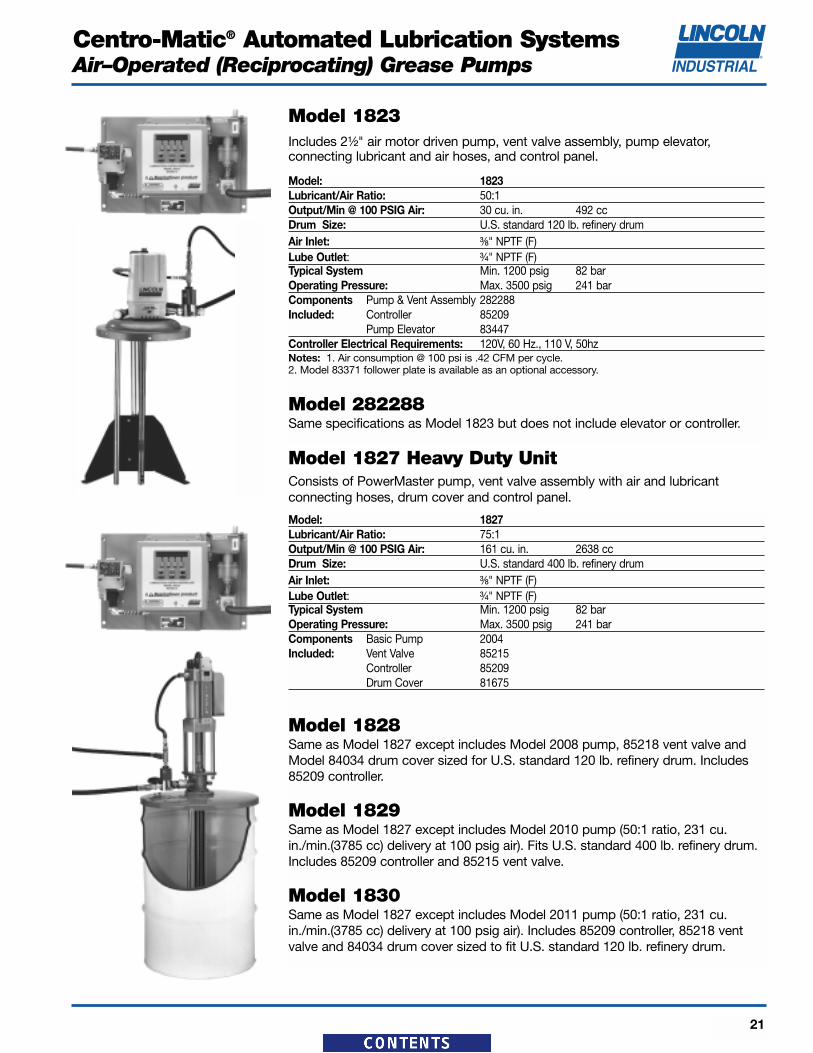
Model 82886 PumpPump discharges lubricant on air-powered forward stroke and vents on spring-powered return stroke through built-in check/vent valve. Reservoir is translucent withspring-loaded follower. Includes filler fitting for refilling reservoir with Model 81834 orother manual pump equipped with Model 645006 coupler.
Model 83668 Same as Model 82886 except includes larger reservoir.
Model 82653 Bare PumpPump uses air for forward and return stroke but dispenses lubricant on forwardstroke only. Return stroke vents lubricant pressure through included check/ventvalve. Translucent reservoir has spring-loaded follower. Refill through included fillerfitting using Model 81834 or other manual pump equipped with Model 645006coupler.
Model 83834 High Volume Bare PumpSame as Model 82653 except 25:1 ratio, 2.15 cu. in (35.2 cc) maximum output.
Model 82655 Pump with ControlsSame as Model 82653 except includes Model 84501 solid state timer and 350244four way electric solenoid valve.
Model 83800 High Volume Pump with ControlsSame as Model 83834 except includes Model 84501 solid state timer and 350244four way electric solenoid valve.
Note: Air consumption @ 100 psi is .15 CFM per stroke.
Lubricant Max. Reservoir Reservoir Air Lube Lubricant Dimensions Air ValveModel /Air Output Capacity Temp. Range Inlet Outlet Oper. Press. HxWxL Required
Model: 83167Lubricant/Air Ratio: 40:1Output/Min @ 100 PSIG Air: 12 cu. in. 197 ccReservoir Capacity: 12 lb. / 5.44 kg 360 cu. in. / 5900 ccAir Inlet: ¹⁄₈" NPTF (F)Lube Outlet: ³⁄₄" NPTF (F)Typical System Min. 1200 psig 82 barOperating Pressure: Max. 3500 psig 241 barDimensions (HxWxL): 22¹⁄₂" x 9 "x 16¹⁄₄" 572 x 229 x 413 mmFilling Method: 81834 Filler PumpReservoir: Translucent AcrylicNotes: 1. Pump requires 3-way air valve. 2. Air consumption @ 100 psi is .15 CFM per cycle
Model 83167Includes transparent reservoir, spring-loaded follower, vent valve assembly andfiller fitting for refilling of reservoir with 81834 filler pump or other manual pumpequipped with Model 645006 coupler.
Model: 83599Lubricant/Air Ratio: 40:1Output/Min @ 100 PSIG Air: 12 cu. in. 197 ccReservoir Capacity: 12 lb. / 5.44 kg 360 cu. in. / 5900 ccAir Inlet: ¹⁄₄" NPTF (F)Lube Outlet: ³⁄₄" NPTF (F)Typical System Min. 1200 psig 82 barOperating Pressure: Max. 3500 psig 241 barDimensions (HxWxL): 24³⁄₈" x 9 "x 18³⁄₁₆" 619 x 229 x 462 mmFilling Method: 81834 Filler PumpReservoir: AluminumNotes: 1. Pump requires 3-way air valve. 2. Air consumption @ 100 psi is .15 CFM per cycle
Model 83599Same as model 83167 except includes model 83744 base mounting kit and metalreservoir with indicator rod for visual check of grease level. Reservoir includesspring-loaded follower.
Model: 84050Lubricant/Air Ratio: 50:1Output/Min @ 100 PSIG Air: 30 cu. in. 492 ccReservoir Capacity: 60 lb. / 27 kg 1800 cu. in. / 29,500 ccAir Inlet: ³⁄₈" NPTF (F)Lube Outlet: ³⁄₄" NPTF (M) at HoseTypical System Min. 1200 psig 82 barOperating Pressure: Max. 3500 psig 241 barDimensions (HxWxL): 31³⁄₄" x 15⁷⁄₁₆ "x 15⁹⁄₁₆" 806 x 392 x 395 mmFilling Method: BulkReservoir: SteelNotes: 1. Pump requires 3-way air valve. 2. Air consumption @ 100 psi is .42 CFM per cycle 3. Optional Model 92597 follower available.
Model 84050A 50:1 ratio double acting air operated pump for high volume displacement. Suppliedwith a 60 pound capacity metal reservoir with removable cover for easy filling. Includesair-operated vent valve and 5' (1.5m) air and lubricant connecting hoses.
Model 85460Same as Model 84050 except includes installed visual low level and follower plate assembly.
Model: 1823Lubricant/Air Ratio: 50:1Output/Min @ 100 PSIG Air: 30 cu. in. 492 ccDrum Size: U.S. standard 120 lb. refinery drumAir Inlet: ³⁄₈" NPTF (F)Lube Outlet: ³⁄₄" NPTF (F)Typical System Min. 1200 psig 82 barOperating Pressure: Max. 3500 psig 241 barComponents Pump & Vent Assembly 282288Included: Controller 85209
Pump Elevator 83447Controller Electrical Requirements: 120V, 60 Hz., 110 V, 50hzNotes: 1. Air consumption @ 100 psi is .42 CFM per cycle.2. Model 83371 follower plate is available as an optional accessory.
Model 282288Same specifications as Model 1823 but does not include elevator or controller.
Model: 1827Lubricant/Air Ratio: 75:1Output/Min @ 100 PSIG Air: 161 cu. in. 2638 ccDrum Size: U.S. standard 400 lb. refinery drumAir Inlet: ³⁄₈" NPTF (F)Lube Outlet: ³⁄₄" NPTF (F)Typical System Min. 1200 psig 82 barOperating Pressure: Max. 3500 psig 241 barComponents Basic Pump 2004Included: Vent Valve 85215
Controller 85209Drum Cover 81675
Model 1828Same as Model 1827 except includes Model 2008 pump, 85218 vent valve andModel 84034 drum cover sized for U.S. standard 120 lb. refinery drum. Includes85209 controller.
Model 1829Same as Model 1827 except includes Model 2010 pump (50:1 ratio, 231 cu.in./min.(3785 cc) delivery at 100 psig air). Fits U.S. standard 400 lb. refinery drum.Includes 85209 controller and 85215 vent valve.
Model 1830Same as Model 1827 except includes Model 2011 pump (50:1 ratio, 231 cu.in./min.(3785 cc) delivery at 100 psig air). Includes 85209 controller, 85218 ventvalve and 84034 drum cover sized to fit U.S. standard 120 lb. refinery drum.
Model 1823Includes 2¹⁄₂" air motor driven pump, vent valve assembly, pump elevator, connecting lubricant and air hoses, and control panel.
Model 1827 Heavy Duty UnitConsists of PowerMaster pump, vent valve assembly with air and lubricant connecting hoses, drum cover and control panel.
Typical System Min. 1200 psig 82 barOperating Pressure: Max. 3500 psig 241 bar
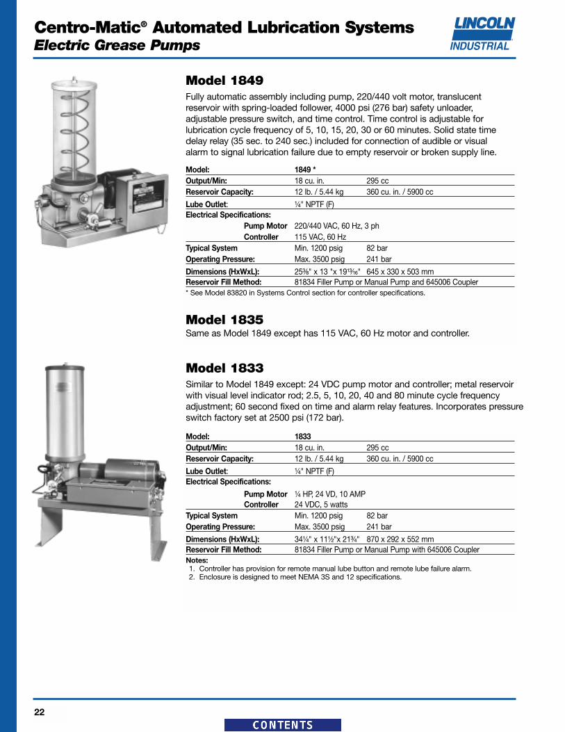
Dimensions (HxWxL): 25³⁄₈" x 13 "x 19¹³⁄₁₆" 645 x 330 x 503 mmReservoir Fill Method: 81834 Filler Pump or Manual Pump and 645006 Coupler* See Model 83820 in Systems Control section for controller specifications.
Model 1835Same as Model 1849 except has 115 VAC, 60 Hz motor and controller.
Model 1849Fully automatic assembly including pump, 220/440 volt motor, translucent reservoir with spring-loaded follower, 4000 psi (276 bar) safety unloader,adjustable pressure switch, and time control. Time control is adjustable for lubrication cycle frequency of 5, 10, 15, 20, 30 or 60 minutes. Solid state timedelay relay (35 sec. to 240 sec.) included for connection of audible or visual alarm to signal lubrication failure due to empty reservoir or broken supply line.
Model: 1833Output/Min: 18 cu. in. 295 ccReservoir Capacity: 12 lb. / 5.44 kg 360 cu. in. / 5900 cc
Typical System Min. 1200 psig 82 barOperating Pressure: Max. 3500 psig 241 bar
Dimensions (HxWxL): 34¹⁄₄" x 11¹⁄₂"x 21³⁄₄" 870 x 292 x 552 mmReservoir Fill Method: 81834 Filler Pump or Manual Pump with 645006 CouplerNotes:1. Controller has provision for remote manual lube button and remote lube failure alarm.2. Enclosure is designed to meet NEMA 3S and 12 specifications.
Model 1833Similar to Model 1849 except: 24 VDC pump motor and controller; metal reservoirwith visual level indicator rod; 2.5, 5, 10, 20, 40 and 80 minute cycle frequencyadjustment; 60 second fixed on time and alarm relay features. Incorporates pressureswitch factory set at 2500 psi (172 bar).
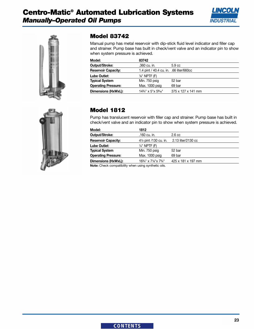
Reservoir Capacity: 4¹⁄₂ pint /130 cu. in. 2.13 liter/2130 ccLube Outlet: ¹⁄₄" NPTF (F)Typical System Min. 750 psig 52 barOperating Pressure: Max. 1000 psig 69 bar
Dimensions (HxWxL): 16³⁄₄" x 7¹⁄₈"x 7³⁄₄" 425 x 181 x 197 mmNote: Check compatibility when using synthetic oils.
Model 1812Pump has translucent reservoir with filler cap and strainer. Pump base has built incheck/vent valve and an indicator pin to show when system pressure is achieved.
Model: 83742Output/Stroke: .360 cu. in. 5.9 ccReservoir Capacity: 1.4 pint / 40.4 cu. in. .66 liter/660cc
Lube Outlet: ¹⁄₈" NPTF (F)Typical System Min. 750 psig 52 barOperating Pressure: Max. 1000 psig 69 bar
Dimensions (HxWxL): 14³⁄₄" x 5"x 5⁹⁄₁₆" 375 x 127 x 141 mm
Model 83742Manual pump has metal reservoir with dip-stick fluid level indicator and filler capand strainer. Pump base has built in check/vent valve and an indicator pin to showwhen system pressure is achieved.
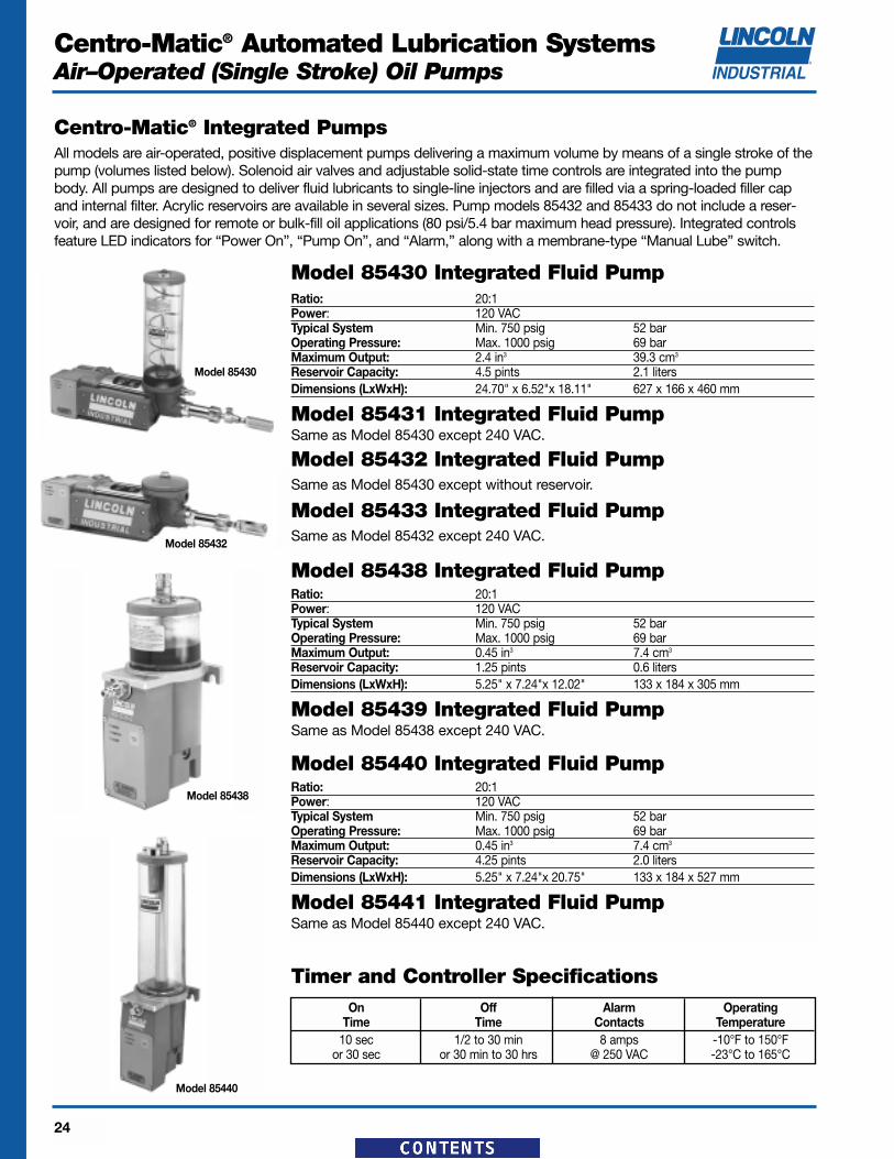
Model 85430 Integrated Fluid PumpRatio: 20:1Power: 120 VACTypical System Min. 750 psig 52 barOperating Pressure: Max. 1000 psig 69 barMaximum Output: 2.4 in3 39.3 cm3
Reservoir Capacity: 4.5 pints 2.1 litersDimensions (LxWxH): 24.70" x 6.52"x 18.11" 627 x 166 x 460 mm
Model 85431 Integrated Fluid PumpSame as Model 85430 except 240 VAC.
Model 85432 Integrated Fluid PumpSame as Model 85430 except without reservoir.
Model 85433 Integrated Fluid PumpSame as Model 85432 except 240 VAC.
Model 85438 Integrated Fluid PumpRatio: 20:1Power: 120 VACTypical System Min. 750 psig 52 barOperating Pressure: Max. 1000 psig 69 barMaximum Output: 0.45 in3 7.4 cm3
Reservoir Capacity: 1.25 pints 0.6 litersDimensions (LxWxH): 5.25" x 7.24"x 12.02" 133 x 184 x 305 mm
Model 85439 Integrated Fluid PumpSame as Model 85438 except 240 VAC.
Model 85440 Integrated Fluid PumpRatio: 20:1Power: 120 VACTypical System Min. 750 psig 52 barOperating Pressure: Max. 1000 psig 69 barMaximum Output: 0.45 in3 7.4 cm3
Reservoir Capacity: 4.25 pints 2.0 litersDimensions (LxWxH): 5.25" x 7.24"x 20.75" 133 x 184 x 527 mm
Model 85441 Integrated Fluid PumpSame as Model 85440 except 240 VAC.
Centro-Matic® Integrated PumpsAll models are air-operated, positive displacement pumps delivering a maximum volume by means of a single stroke of thepump (volumes listed below). Solenoid air valves and adjustable solid-state time controls are integrated into the pumpbody. All pumps are designed to deliver fluid lubricants to single-line injectors and are filled via a spring-loaded filler capand internal filter. Acrylic reservoirs are available in several sizes. Pump models 85432 and 85433 do not include a reser-voir, and are designed for remote or bulk-fill oil applications (80 psi/5.4 bar maximum head pressure). Integrated controlsfeature LED indicators for “Power On”, “Pump On”, and “Alarm,” along with a membrane-type “Manual Lube” switch.
Timer and Controller SpecificationsOn Off Alarm Operating
Time Time Contacts Temperature10 sec 1/2 to 30 min 8 amps -10°F to 150°F
or 30 sec or 30 min to 30 hrs @ 250 VAC -23°C to 165°C
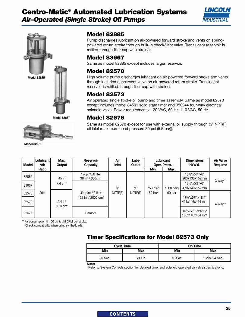
Model 82885Pump discharges lubricant on air-powered forward stroke and vents on spring-powered return stroke through built-in check/vent valve. Translucent reservoir isrefilled through filler cap with strainer.
Model 83667Same as model 82885 except includes larger reservoir.
Model 82570High volume pump discharges lubricant on air-powered forward stroke and ventsthrough included check/vent valve on air-powered return stroke. Translucent reservoir is refilled through filler cap with strainer.
Model 82573Air operated single stroke oil pump and timer assembly. Same as model 82570except includes model 84501 solid state timer and 350244 four-way electricalsolenoid valve. Power requirements: 120 VAC, 60 Hz; 110 VAC, 50 Hz.
Model 82676Same as model 82570 except for use with external oil supply through ¹⁄₂" NPT(F)oil inlet (maximum head pressure 80 psi (5.5 bar)).
** Air consumption @ 100 psi is .15 CFM per stroke. Check compatibility when using synthetic oils.
Lubricant Max. Reservoir Air Lube Lubricant Dimensions Air ValveModel /Air Output Capacity Inlet Outlet Oper. Press. HxWxL Required
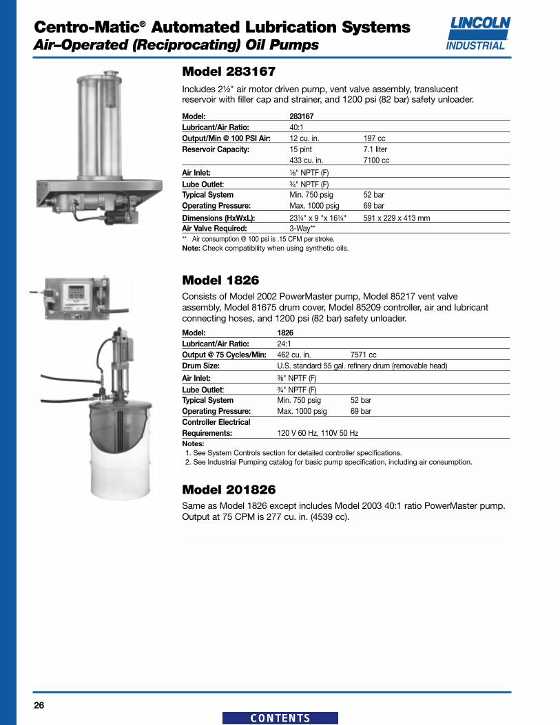
Air Inlet: ¹⁄₈" NPTF (F)Lube Outlet: ³⁄₄" NPTF (F)Typical System Min. 750 psig 52 barOperating Pressure: Max. 1000 psig 69 bar
Dimensions (HxWxL): 23¹⁄₄" x 9 "x 16¹⁄₄" 591 x 229 x 413 mmAir Valve Required: 3-Way**** Air consumption @ 100 psi is .15 CFM per stroke.Note: Check compatibility when using synthetic oils.
Model 283167Includes 2¹⁄₂" air motor driven pump, vent valve assembly, translucent reservoir with filler cap and strainer, and 1200 psi (82 bar) safety unloader.
Model: 1826Lubricant/Air Ratio: 24:1Output @ 75 Cycles/Min: 462 cu. in. 7571 ccDrum Size: U.S. standard 55 gal. refinery drum (removable head)
Air Inlet: ³⁄₈" NPTF (F)Lube Outlet: ³⁄₄" NPTF (F)Typical System Min. 750 psig 52 barOperating Pressure: Max. 1000 psig 69 barController Electrical Requirements: 120 V 60 Hz, 110V 50 HzNotes:1. See System Controls section for detailed controller specifications.2. See Industrial Pumping catalog for basic pump specification, including air consumption.
Model 201826Same as Model 1826 except includes Model 2003 40:1 ratio PowerMaster pump.Output at 75 CPM is 277 cu. in. (4539 cc).
Model 1826Consists of Model 2002 PowerMaster pump, Model 85217 vent valve assembly, Model 81675 drum cover, Model 85209 controller, air and lubricant connecting hoses, and 1200 psi (82 bar) safety unloader.
Typical System Min. 750 psig 52 barOperating Pressure: Max. 1000 psig 69 bar
Dimensions (HxWxL): 25³⁄₈" x 13 "x 19¹³⁄₁₆" 645 x 330 x 503 mmNote: See #83820, System Controls section for controller specifications.
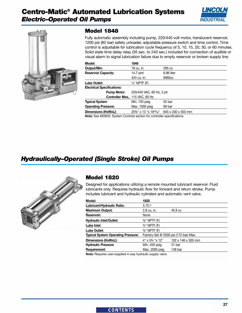
Model 1848Fully automatic assembly including pump, 220/440 volt motor, translucent reservoir,1200 psi (82 bar) safety unloader, adjustable pressure switch and time control. Timecontrol is adjustable for lubrication cycle frequency of 5, 10, 15, 20, 30, or 60 minutes.Solid state time delay relay (35 sec. to 240 sec.) included for connection of audible orvisual alarm to signal lubrication failure due to empty reservoir or broken supply line.
Dimensions (HxWxL): 4" x 5³⁄₄ "x 12" 102 x 146 x 305 mmHydraulic Pressure Min. 450 psig 31 barRequirement: Max. 2000 psig 138 barNote: Requires user-supplied 4-way hydraulic supply valve.
Model 1820Designed for applications utilizing a remote mounted lubricant reservoir. Fluidlubricants only. Requires hydraulic flow for forward and return stroke. Pumpincludes lubricant and hydraulic cylinders and automatic vent valve.
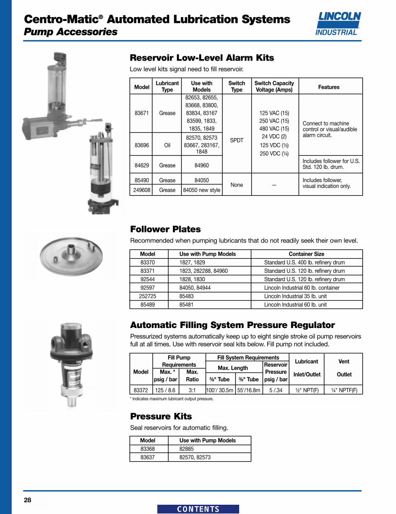
Follower PlatesRecommended when pumping lubricants that do not readily seek their own level.
Model Use with Pump Models Container Size83370 1827, 1829 Standard U.S. 400 lb. refinery drum83371 1823, 282288, 84960 Standard U.S. 120 lb. refinery drum92544 1828, 1830 Standard U.S. 120 lb. refinery drum92597 84050, 84944 Lincoln Industrial 60 lb. container252725 85483 Lincoln Industrial 35 lb. unit85489 85481 Lincoln Industrial 60 lb. unit
Pressure KitsSeal reservoirs for automatic filling.
Model Use with Pump Models83368 8288583637 82570, 82573
Automatic Filling System Pressure RegulatorPressurized systems automatically keep up to eight single stroke oil pump reservoirsfull at all times. Use with reservoir seal kits below. Fill pump not included.
Fill Pump Fill System RequirementsLubricant VentRequirements Reservoir
Model Max. * Max.Max. Length
Pressure Inlet/Outlet Outletpsig / bar Ratio ⁵⁄₈" Tube ³⁄₈" Tube psig / bar
Max 31 cc Coupler 26³⁄₄ 14 91 pint/ 30 pints 5' 80599 679 356 229
1254 Oil 7 strokes14.2 L 1.5 m
Non-Drip473 cc Nozzle
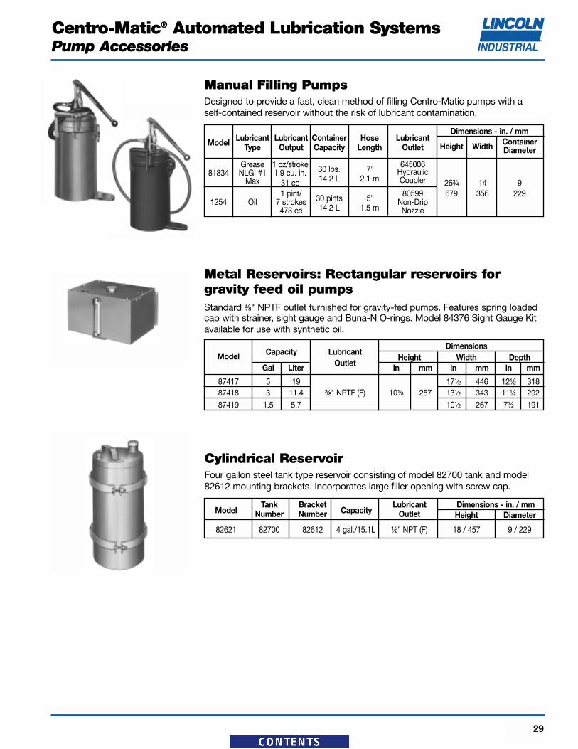
Manual Filling PumpsDesigned to provide a fast, clean method of filling Centro-Matic pumps with a self-contained reservoir without the risk of lubricant contamination.
Metal Reservoirs: Rectangular reservoirs for gravity feed oil pumpsStandard ³⁄₈" NPTF outlet furnished for gravity-fed pumps. Features spring loadedcap with strainer, sight gauge and Buna-N O-rings. Model 84376 Sight Gauge Kitavailable for use with synthetic oil.
Cylindrical ReservoirFour gallon steel tank type reservoir consisting of model 82700 tank and model82612 mounting brackets. Incorporates large filler opening with screw cap.
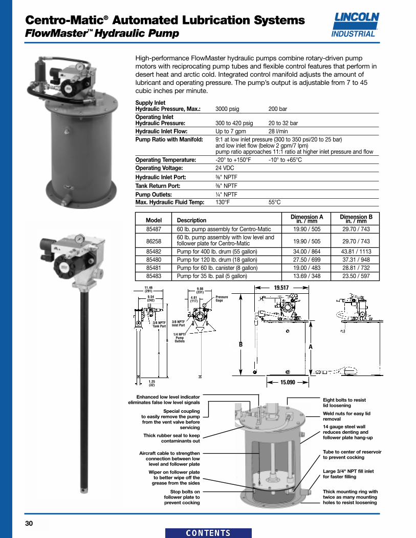
High-performance FlowMaster hydraulic pumps combine rotary-driven pumpmotors with reciprocating pump tubes and flexible control features that perform indesert heat and arctic cold. Integrated control manifold adjusts the amount oflubricant and operating pressure. The pump’s output is adjustable from 7 to 45cubic inches per minute.
Supply InletHydraulic Pressure, Max.: 3000 psig 200 barOperating InletHydraulic Pressure: 300 to 420 psig 20 to 32 barHydraulic Inlet Flow: Up to 7 gpm 28 l/minPump Ratio with Manifold: 9:1 at low inlet pressure (300 to 350 psi/20 to 25 bar)
and low inlet flow (below 2 gpm/7 lpm)pump ratio approaches 11:1 ratio at higher inlet pressure and flow
Operating Temperature: -20° to +150°F -10° to +65°COperating Voltage: 24 VDC
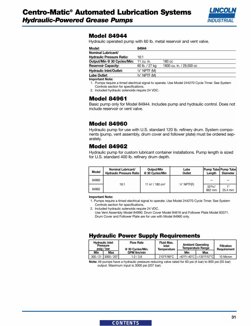
Model: 84944Nominal Lubricant/Hydraulic Pressure Ratio: 16:1Output/Min @ 30 Cycles/Min: 11 cu. in. 180 ccReservoir Capacity: 60 lb. / 27 kg 1800 cu. in. / 29,500 ccHydraulic Inlet/Outlet: ¹⁄₄" NPTF (M) Lube Outlet: ³⁄₄" NPTF (M)Important Note: 1. Pumps require a timed electrical signal to operate. Use Model 244270 Cycle Timer. See System
Controls section for specifications.2. Included hydraulic solenoids require 24 VDC.
Model 84961Basic pump only for Model 84944. Includes pump and hydraulic control. Does notinclude reservoir or vent valve.
Model 84960Hydraulic pump for use with U.S. standard 120 lb. refinery drum. System compo-nents (pump, vent assembly, drum cover and follower plate) must be ordered sep-arately.
Model 84962Hydraulic pump for custom lubricant container installations. Pump length is sizedfor U.S. standard 400 lb. refinery drum depth.
Model 84944Hydraulic operated pump with 60 lb. metal reservoir and vent valve.
Hydraulic Power Supply RequirementsHydraulic Inlet Flow Rate Fluid Max.
Ambient OperatingPressure InletTemperature Range
Filtration psig / bar @ 30 Cycles/Min. Temperature Requirement
Min Max GPM ltrs/min Min Max300 / 21 3000 / 207 1.0 / 3.8 210°F/99°C -40°F/-40°C +135°F/57°C 10 Micron
Note: All pumps have a hydraulic pressure reducing valve rated for 60 psi (4 bar) to 800 psi (55 bar) output. Maximum input is 3000 psi (207 bar).
Important Note: 1. Pumps require a timed electrical signal to operate. Use Model 244270 Cycle Timer. See System
Controls section for specifications. 2. Included hydraulic solenoids require 24 VDC.
Use Vent Assembly Model 84990; Drum Cover Model 84616 and Follower Plate Model 83371.Drum Cover and Follower Plate are for use with Model 84960 only.
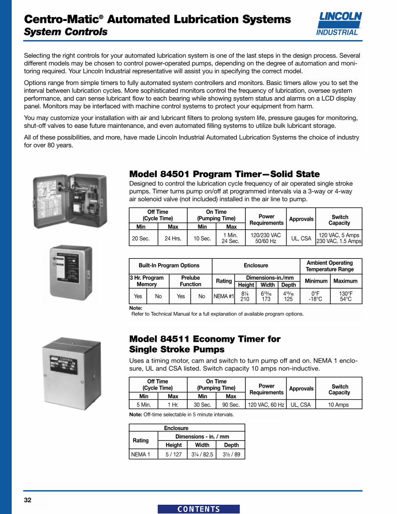
Model 84501 Program Timer—Solid StateDesigned to control the lubrication cycle frequency of air operated single strokepumps. Timer turns pump on/off at programmed intervals via a 3-way or 4-way air solenoid valve (not included) installed in the air line to pump.
Off Time On TimePower Approvals Switch(Cycle Time) (Pumping Time)
Requirements CapacityMin Max Min Max
20 Sec. 24 Hrs. 10 Sec. 1 Min. 120/230 VAC UL, CSA 120 VAC, 5 Amps24 Sec. 50/60 Hz 230 VAC, 1.5 Amps
Model 84511 Economy Timer for Single Stroke PumpsUses a timing motor, cam and switch to turn pump off and on. NEMA 1 enclo-sure, UL and CSA listed. Switch capacity 10 amps non-inductive.
Off Time On TimePower Approvals Switch(Cycle Time) (Pumping Time)
Requirements CapacityMin Max Min Max
5 Min. 1 Hr. 30 Sec. 90 Sec. 120 VAC, 60 Hz UL, CSA 10 Amps
Built-In Program Options Enclosure Ambient Operating Temperature Range
3 Hr. Program Prelube Rating Dimensions-in./mm Minimum MaximumMemory Function Height Width Depth
Yes No Yes No NEMA #1 8¹⁄₄ 6¹³⁄₁₆ 4¹⁵⁄₁₆ 0°F 130°F210 173 125 -18°C 54°C
Enclosure
RatingDimensions - in. / mm
Height Width Depth
NEMA 1 5 / 127 3¹⁄₄ / 82.5 3¹⁄₂ / 89
Note: Off-time selectable in 5 minute intervals.
Selecting the right controls for your automated lubrication system is one of the last steps in the design process. Severaldifferent models may be chosen to control power-operated pumps, depending on the degree of automation and moni-toring required. Your Lincoln Industrial representative will assist you in specifying the correct model.
Options range from simple timers to fully automated system controllers and monitors. Basic timers allow you to set theinterval between lubrication cycles. More sophisticated monitors control the frequency of lubrication, oversee systemperformance, and can sense lubricant flow to each bearing while showing system status and alarms on a LCD displaypanel. Monitors may be interfaced with machine control systems to protect your equipment from harm.
You may customize your installation with air and lubricant filters to prolong system life, pressure gauges for monitoring,shut-off valves to ease future maintenance, and even automated filling systems to utilize bulk lubricant storage.
All of these possibilities, and more, have made Lincoln Industrial Automated Lubrication Systems the choice of industryfor over 80 years.
Note:Refer to Technical Manual for a full explanation of available program options.
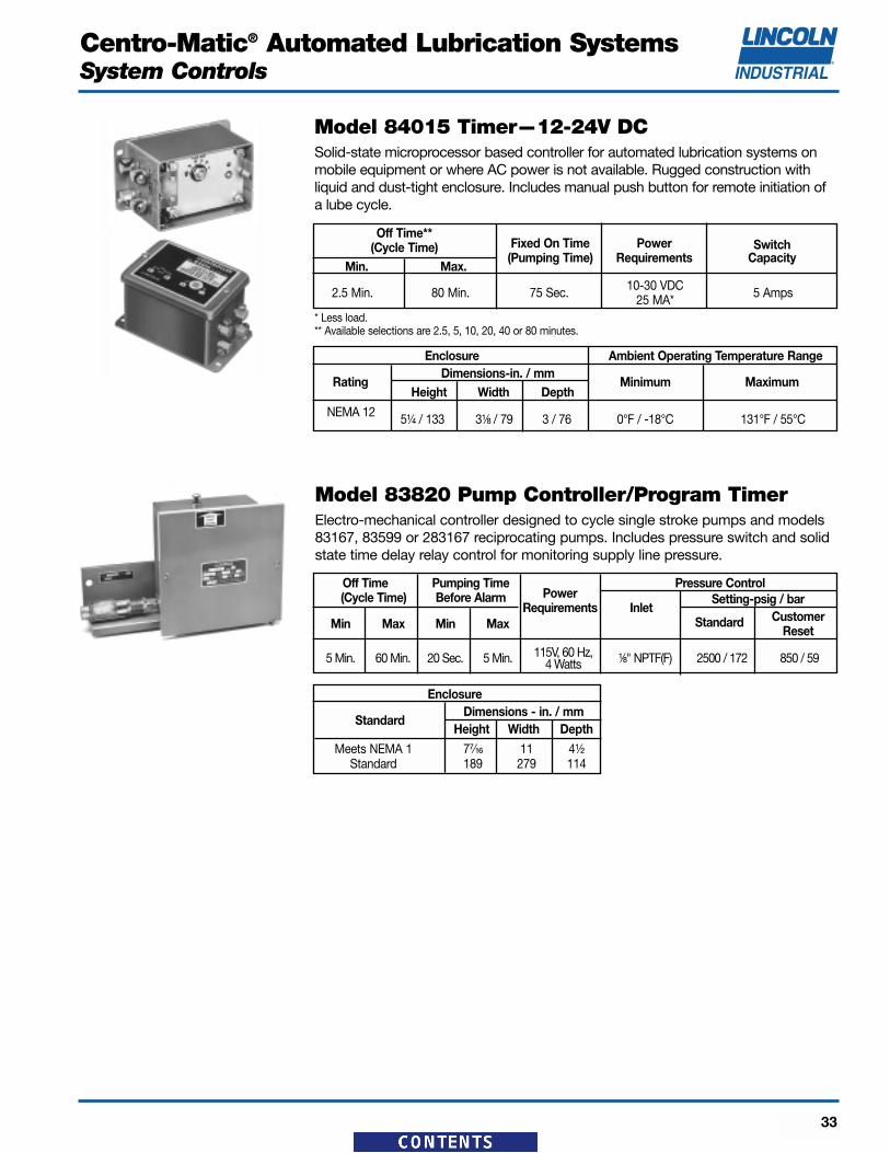
Model 84015 Timer—12-24V DCSolid-state microprocessor based controller for automated lubrication systems onmobile equipment or where AC power is not available. Rugged construction withliquid and dust-tight enclosure. Includes manual push button for remote initiation ofa lube cycle.
Model 83820 Pump Controller/Program TimerElectro-mechanical controller designed to cycle single stroke pumps and models83167, 83599 or 283167 reciprocating pumps. Includes pressure switch and solidstate time delay relay control for monitoring supply line pressure.
Off Time Pumping TimePower
Pressure Control(Cycle Time) Before Alarm
Requirements InletSetting-psig / bar
Min Max Min Max Standard Customer Reset
5 Min. 60 Min. 20 Sec. 5 Min. 115V, 60 Hz, ¹⁄₈" NPTF(F) 2500 / 172 850 / 594 Watts
Power Requirements External Ambient Panel Current Alarm Temperature Dimensions
Voltage (less load) Load Range in. / mmCapacity Height Width
120 VAC, 60 Hz47 VA 360 VA
32° to 122°F 12 18¹⁄₄110 VAC, 50 Hz 0° to +50°C 305 464
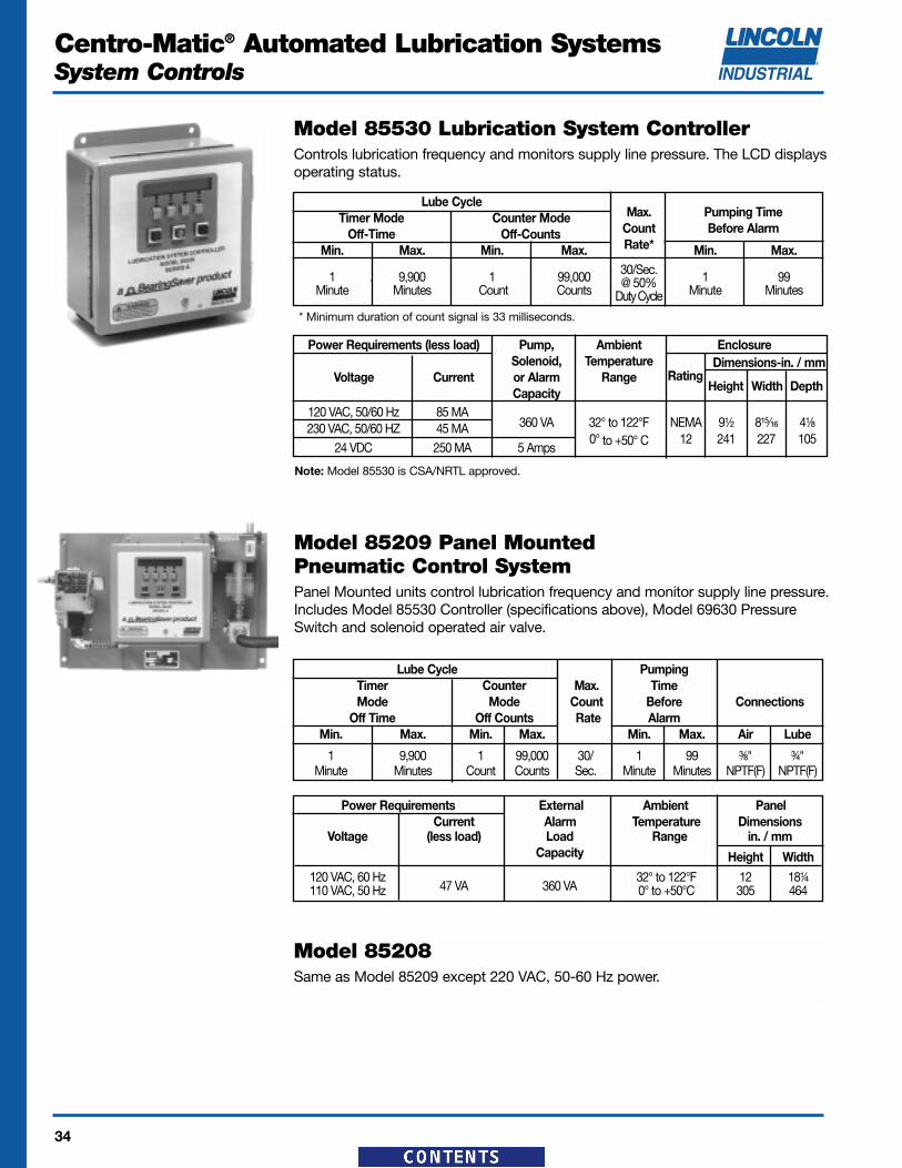
Model 85209 Panel Mounted Pneumatic Control System Panel Mounted units control lubrication frequency and monitor supply line pressure.Includes Model 85530 Controller (specifications above), Model 69630 PressureSwitch and solenoid operated air valve.
Lube Cycle PumpingTimer Counter Max. TimeMode Mode Count Before Connections
Off Time Off Counts Rate AlarmMin. Max. Min. Max. Min. Max. Air Lube
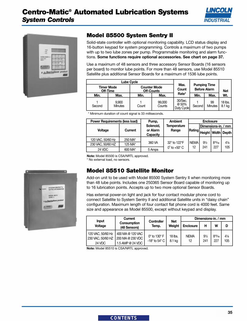
Model 85500 System Sentry IISolid-state controller with optional monitoring capability. LCD status display and16-button keypad for system programming. Controls a maximum of two pumpswith up to two lube zones per pump. Programmable monitoring and alarm func-tions. Some functions require optional accessories. See chart on page 37.
Use a maximum of 48 sensors and three accessory Sensor Boards (16 sensorsper board) to monitor lube points. For more than 48 sensors, use Model 85510Satellite plus additional Sensor Boards for a maximum of 1536 lube points.
Model 85510 Satellite MonitorAdd-on unit to be used with Model 85500 System Sentry II when monitoring morethan 48 lube points. Includes one 250365 Sensor Board capable of monitoring upto 16 lubrication points. Accepts up to two more optional Sensor Boards.
Has external power-on light and jack for four contact modular phone cord to connect Satellite to System Sentry II and additional Satellite units in “daisy chain”configuration. Maximum length of four contact flat phone cord is 4000 feet. Samesize and appearance as Model 85500, except without keypad and display.
Lube CycleMax. Pumping Time
Timer Mode Counter Mode Count Before AlarmOff-Time Off-Counts NetMin. Max. Min. Max. Rate* Min. Max. Wt.
Model 247333 Pressure TransducerPressure Transducer signals actual system pressure via LCD display of SystemSentry II. Comes with 72 inch (1.8m) shielded 24-gauge connecting wire.Maximum length of wire between transducer and monitor is 30 (9.1m) feet.
Range Accuracy Proof Pressure Ambient Voltage EnclosureConnection Temp. Input Output Offset
NEMA 4X0 to
±1%7500 psig ¹⁄₄" NPT -20° to 180° F 10 to 1-6 1 Rating
4000 psi 517 bar Male Thread -29° to 82° C 30 VDC VDC 300 Series276 bar VDC Stainless
Steel
Lubricant Min. Flow Inlet/ Min. IntervalModel Description Construction
Temp. Range Per EventBetween Lube
Outlet Flow Event
250400Straight Sensor
Assembly Brass Sensor
25049090° Sensor & Plated Steel
32° to 145° FAssemblyCheck Body
0° to 63° C1/8" 30 Seconds
250500Straight Sensor Sensor &
Assembly Check Body
25059090° Sensor 316 Assembly Stainless Steel
Model 250365 Sensor BoardPlug-in accessory board used with Model 85500 and Model 85510 that allows theattachment of up to 16 lube flow sensors. (Model 85500 comes without boardsinstalled and can hold up to a total of three. Model 85510 comes with one boardinstalled and can hold up to two more for a total of three.)
Sensor AssembliesSensor assemblies consist of a check body and lube sensor with attached 30'cable. Cables are epoxy potted into the sensors for a watertight seal. Sensorshave a ³⁄₈" pipe thread for conduit connection and a Viton o-ring seal. Check bodies terminate in a ¹⁄₈" NPTF male thread for attachment to a bearing or otherlubricant inlet. Maximum working pressure 6,000 psi (414 bar). Maximum wirerun from sensor to monitor is 500 feet (152m).
.004 cu.in./.066 cc@ 32°F / 0° C to
125°F / 52°C
.008 in3 / .131cc@ 126ºF / 53ºC to
145ºF / 63ºC
Model 243100 Sensor Wire100 foot (30.5 meters) coil of 2 conductor 22 gauge wire for connecting sensorsto monitor. Maximum length of wire between sensor and monitor is 500 feet
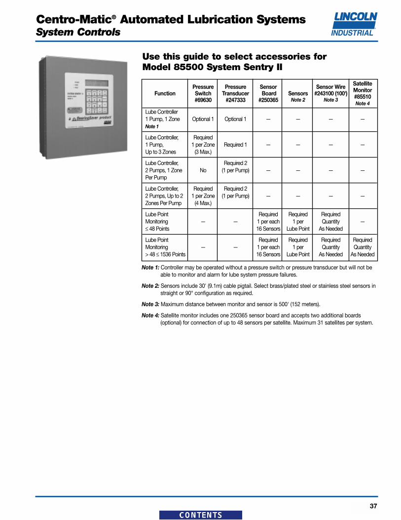
Lube Controller, Required1 Pump, 1 per Zone Required 1 — — — —Up to 3 Zones (3 Max.)
Lube Controller, Required 22 Pumps, 1 Zone No (1 per Pump) — — — —Per Pump
Lube Controller, Required Required 22 Pumps, Up to 2 1 per Zone (1 per Pump) — — — —Zones Per Pump (4 Max.)
Lube Point Required Required RequiredMonitoring — — 1 per each 1 per Quantity —≤ 48 Points 16 Sensors Lube Point As Needed
Lube Point Required Required Required RequiredMonitoring — — 1 per each 1 per Quantity Quantity> 48 ≤ 1536 Points 16 Sensors Lube Point As Needed As Needed
Note 1: Controller may be operated without a pressure switch or pressure transducer but will not beable to monitor and alarm for lube system pressure failures.
Note 2: Sensors include 30' (9.1m) cable pigtail. Select brass/plated steel or stainless steel sensors instraight or 90° configuration as required.
Note 3: Maximum distance between monitor and sensor is 500' (152 meters).
Note 4: Satellite monitor includes one 250365 sensor board and accepts two additional boards(optional) for connection of up to 48 sensors per satellite. Maximum 31 satellites per system.
Use this guide to select accessories for Model 85500 System Sentry II
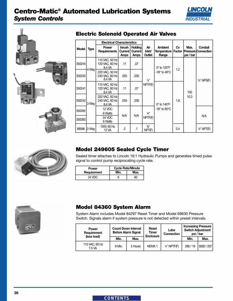
Model 249605 Sealed Cycle TimerSealed timer attaches to Lincoln 16:1 Hydraulic Pumps and generates timed pulsesignal to control pump reciprocating cycle rate.
Power Cycle Rate/MinuteRequirement Min. Max.
24 VDC 6 60
Electric Solenoid Operated Air Valves
Electrical CharacteristicsPower Inrush Holding Air Ambient Cv Max. ConduitModel Type
Requirements Current Current Inlet/ Temperature Factor Pressure ConnectionAmps Amps Outlet Range psi / bar
110 VAC, 50 Hz350244 120 VAC, 60 Hz .11 .07
4-Way 8.4 VA 0° to 120°F 1.2220 VAC, 50 Hz -18° to 49°C
Model 84360 System AlarmSystem Alarm includes Model 84297 Reset Timer and Model 69630 PressureSwitch. Signals alarm if system pressure is not detected within preset intervals.
Power Count Down Interval ResetIncreasing Pressure
Requirement Before Alarm Signal TimerLube Switch Adjustment
(less load) EnclosureConnection psi / bar
Min. Max. Min. Max.
115 VAC, 60 Hz 9 Min. 5 Hours NEMA 1 ¹⁄₄" NPTF(F) 280 / 19 3000 / 2077.5 VA
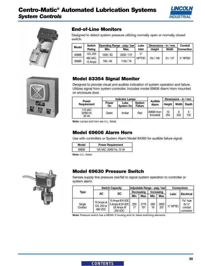
Model 83354 Signal MonitorDesigned to provide visual and audible indication of system operation and failure.Utilizes signal from system controller. Includes model 69606 Alarm Horn mountedon enclosure door.
Model 69606 Alarm HornUse with controllers or System Alarm Model 84360 for audible failure signal.
PowerIndicator Lamps
AudibleDimensions - in / mm
Requirement Power Lube System AlarmOn System On Failure Height Width Depth
115 VAC69606 Horn 10 8 650/60 Hz Green Amber Red(included) 254 203 15235 VA
Model Power Requirement
69606 120 VAC, 50/60 Hz, 15 VA
Model 69630 Pressure SwitchSenses supply line pressure rise/fall to signal system operation to controller or system alarm.
Switch Capacity Adjustable Range - psig / bar ConnectionsType Decreasing Increasing
Centro-Matic® Automated Lubrication SystemsAirCare™ Air Preparation Systems
46
Miniature Air Line Combination UnitsFilter-Lubricator
ModelMax. Air Operating Element Lubricator
No.Supply Temperature Particle Bowl Capacity
psig / bar Range - F / C Size ozs. / ml85674 150 / 10.3 0 to 125 / -18 to 52 5� 1.0 / 30
Modular Air Line Equipment Accessories—Lockout ValveInstall in-line or modular with other AirCare products to help conform to OSHALockout Regulations. In the closed position, valves block inlet air flow and exhaustdownstream air.
ModelFor For Max. Operating
No.Modular In-Line Air Supply Temperatureuse with use with psig / bar Range-F / C
247770 ¹⁄₄" Modular ¹⁄₄"247771 ³⁄₈" Modular ³⁄₈" 250 0 to 150247772 ¹⁄₂" Modular ¹⁄₂" 17 -20 to 65
247773 ³⁄₄" Modular ³⁄₄"
Modular Air Line Equipment Accessories—Quick ClampUse with Modular Air Line Components to provide modular installation capability.Flanges on the products slide into “V” grooves in the quick clamp. Two face-seal-ing o-rings in the quick clamp provide an air tight connection when the clamp isclosed.
Model For Modular DimensionsNo. Sizes in. / mm
247782 ¹⁄₄" and ³⁄₈" 1.50 / 38247783 ¹⁄₂" and ³⁄₄" 2.00 / 51
Modular Air Line Equipment Accessories—Quick Clamp Wall Mounting BracketUse with quick clamp to provide secure mounting to a wall, machine panel, orother flat surface.
Model For Modular Dimensions in. / mmNo. Sizes A B C
Centro-Matic® Automated Lubrication SystemsAirCare™ Air Preparation Systems
47
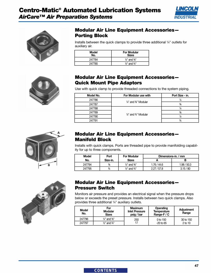
Modular Air Line Equipment Accessories—Porting BlockInstalls between the quick clamps to provide three additional ¹⁄₄" outlets for auxiliary air.
Model For ModularNo. Sizes
247784 ¹⁄₄" and ³⁄₈"247785 ¹⁄₂" and ³⁄₄"
Modular Air Line Equipment Accessories—Quick Mount Pipe AdaptorsUse with quick clamp to provide threaded connections to the system piping.
Model No. For Modular use with Port Size - in.247786
¹⁄₄" and ³⁄₈" Modular¹⁄₄
247787 ³⁄₈
247788 ¹⁄₄
247789¹⁄₂" and ³⁄₄" Modular
³⁄₈
247790 ¹⁄₂
247791 ³⁄₄
Modular Air Line Equipment Accessories—Manifold BlockInstalls with quick clamps. Ports are threaded pipe to provide manifolding capabil-ity for up to three components.
Model Port For Modular Dimensions-in. / mmNo. Size-in. Sizes A B
Modular Air Line Equipment Accessories—Pressure SwitchMonitors air pressure and provides an electrical signal when the pressure dropsbelow or exceeds the preset pressure. Installs between two quick clamps. Alsoprovides three additional ¹⁄₄" auxiliary outlets.
ModelFor Maximum Operating
No.Modular Inlet Pressure Temperature Adjustment
Sizes psig / bar Range-F / C Range
247796 ¹⁄₄" and ³⁄₈" 250 0 to 150 30 to 150247797 ¹⁄₂" and ³⁄₄" 17 -20 to 65 2 to 10
Centro-Matic® Automated Lubrication SystemsAirCare™ Air Preparation Systems
48
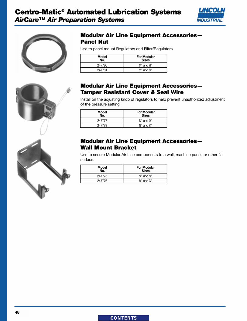
Modular Air Line Equipment Accessories—Panel NutUse to panel mount Regulators and Filter/Regulators.
Model For ModularNo. Sizes
247780 ¹⁄₄" and ³⁄₈"247781 ¹⁄₂" and ³⁄₄"
Modular Air Line Equipment Accessories—Wall Mount BracketUse to secure Modular Air Line components to a wall, machine panel, or other flatsurface.
Model For ModularNo. Sizes
247775 ¹⁄₄" and ³⁄₈"247776 ¹⁄₂" and ³⁄₄"
Modular Air Line Equipment Accessories—Tamper Resistant Cover & Seal WireInstall on the adjusting knob of regulators to help prevent unauthorized adjustmentof the pressure setting.
Centro-Matic® Automated Lubrication SystemsAirCare™ Air Preparation Systems
49
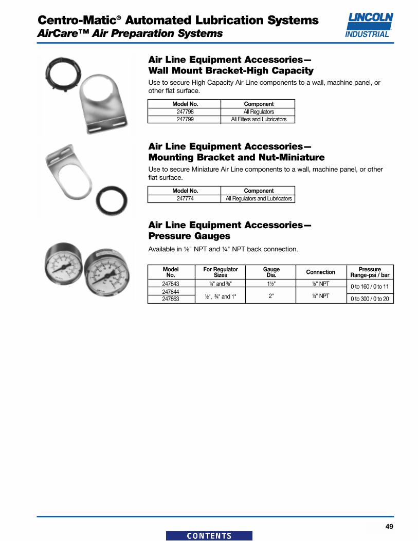
Air Line Equipment Accessories—Wall Mount Bracket-High CapacityUse to secure High Capacity Air Line components to a wall, machine panel, orother flat surface.
Model No. Component247798 All Regulators247799 All Filters and Lubricators
Air Line Equipment Accessories—Mounting Bracket and Nut-MiniatureUse to secure Miniature Air Line components to a wall, machine panel, or otherflat surface.
Model No. Component247774 All Regulators and Lubricators
Air Line Equipment Accessories—Pressure GaugesAvailable in ¹⁄₈" NPT and ¹⁄₄" NPT back connection.
Model For Regulator Gauge Connection PressureNo. Sizes Dia. Range-psi / bar
247843 ¹⁄₄" and ³⁄₈" 1¹⁄₂" ¹⁄₈" NPT 0 to 160 / 0 to 11247844
¹⁄₂", ³⁄₄" and 1" 2" ¹⁄₄" NPT247863 0 to 300 / 0 to 20
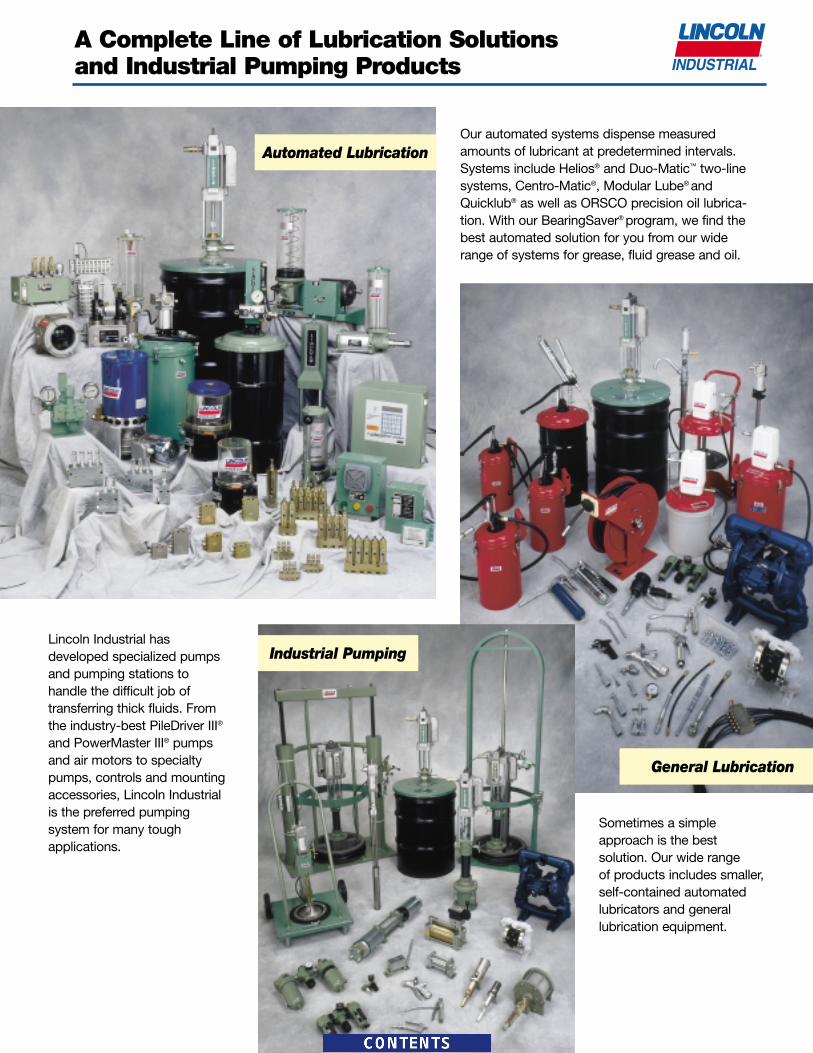
A Complete Line of Lubrication Solutionsand Industrial Pumping Products
Our automated systems dispense measuredamounts of lubricant at predetermined intervals.Systems include Helios® and Duo-Matic™ two-linesystems, Centro-Matic®, Modular Lube® andQuicklub® as well as ORSCO precision oil lubrica-tion. With our BearingSaver® program, we find the best automated solution for you from our wide range of systems for grease, fluid grease and oil.
Lincoln Industrial has developed specialized pumpsand pumping stations to handle the difficult job of transferring thick fluids. Fromthe industry-best PileDriver III®
and PowerMaster III® pumpsand air motors to specialtypumps, controls and mountingaccessories, Lincoln Industrialis the preferred pumping system for many tough applications.
Sometimes a simpleapproach is the best solution. Our wide range of products includes smaller,self-contained automatedlubricators and general lubrication equipment.
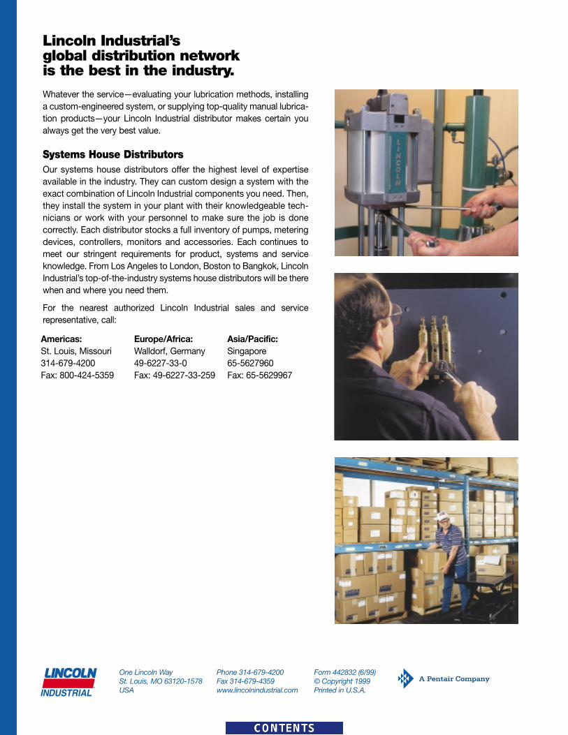
Lincoln Industrial’s global distribution network is the best in the industry.
Whatever the service—evaluating your lubrication methods, installinga custom-engineered system, or supplying top-quality manual lubrica-tion products—your Lincoln Industrial distributor makes certain youalways get the very best value.
Systems House DistributorsOur systems house distributors offer the highest level of expertiseavailable in the industry. They can custom design a system with theexact combination of Lincoln Industrial components you need. Then,they install the system in your plant with their knowledgeable tech-nicians or work with your personnel to make sure the job is donecorrectly. Each distributor stocks a full inventory of pumps, meteringdevices, controllers, monitors and accessories. Each continues tomeet our stringent requirements for product, systems and serviceknowledge. From Los Angeles to London, Boston to Bangkok, LincolnIndustrial’s top-of-the-industry systems house distributors will be therewhen and where you need them.
For the nearest authorized Lincoln Industrial sales and service representative, call: