. • -r CEOCOR CR2 "C.D." FINAL REPORT (december 1987) TITLE: Cathodic Disbonding of Steel Pipe Coatings Prepared by the CEOCOR-Subcommittee CR2 "C.D." The Subcommittee consisted of: Ir. P.D. Marijs Ing. G. Camitz Mr. D. Gray Mr. T. Huguency Ing. P. Pecheur Ir. D. Koster Dr. M. Schulze Dr.Ing. A. Siniscalchi Dr. F. Stalder Drs. J. van der Schaaf Key & Kramer B.V. (Chairman) Swedish Corrosion Institute British Gas Corporation Gaz de France Tubemeuse N.V. Nederlandse Gasunie Mannesmann Forschungs- Institut GmbH SNAM S.p.A. Korrosionskommission (CH.) Key & Kramer B.V.
Transcript
-------------------~--~---. • -r
CEOCOR CR2 "C.D."
FINAL REPORT
(december 1987)
TITLE: Cathodic Disbonding of Steel Pipe Coatings
Prepared by the CEOCOR-Subcommittee CR2 "C.D."
The Subcommittee consisted of:
Ir. P.D. Marijs Ing. G. Camitz Mr. D. Gray Mr. T. Huguency Ing. P. Pecheur Ir. D. Koster Dr. M. Schulze
Dr.Ing. A. Siniscalchi Dr. F. Stalder Drs. J. van der Schaaf
Key & Kramer B.V. (Chairman) Swedish Corrosion Institute British Gas Corporation Gaz de France Tubemeuse N.V. Nederlandse Gasunie Mannesmann ForschungsInstitut GmbH SNAM S.p.A. Korrosionskommission (CH.) Key & Kramer B.V.
These blisters contain neutral water which has permeated the coating.
This type of wate~ permeation is inevitable with all organic coatings
but its rate depends on coating type, thickness, temperature gradient,
etc.
2.3 Osmosis and Electro-Osmosis
The presence of water soluble material on the steel surface (due to
improper cleaning of the surface, or to the application of unsuitable
primers) can give rise to water permeation through a coating due to
osmosis. Osmosis occurs with every type of organic coating, but at
different rates, depending on the coating.
Ions can enter certain materials with polar molecular groups and
especially so if there are coherent phase boundaries within the
material. An electric field across the coating thickness encourages
migration. not only of ions, but also of water through the film. This
process is generally known as electro-osmosis. In most cases water
migrates to the cathode resulting in the formation of blisters and
sometimes the destruction of the coating. Where cathodic polarisation
of the steel occurs, the blisters contain an alkaline solution,
whereas anodic polarisation produces an acidic solution and pits in
the steel.
2.4 Cathodic Disbonding
All previous~y described types ef adhesion loss are due to permeat_ion
of substances :hrough intact coatings. In contrast to this, cathodic
- .'
disbonding starts from coating holidays and is chara:terised by
moisture creeping along the interface between the coating and the
steel, thus causing loss of coating adhesion. The resultant pH of the
interfacial liquid can be 13 or higher.
The alkalinity of the moisture is the result of cathodic polarisation
either due to the formation of a corrosion cell, or to stray-current
influence or to cathodic protection of the steel. Pipelines without
___ ca_t_hQdic_-pr.ot§J:Li9n-ID9Y~ ca thodicall" polari~e~~erj&_in local
spots, such as the cathodic surface in a (galvanic) corrosion cell,
and at the point of entrance of DC-stray currents. On cathodically
prote~ted pipelines the entire steel surface is cathodically
polarised.
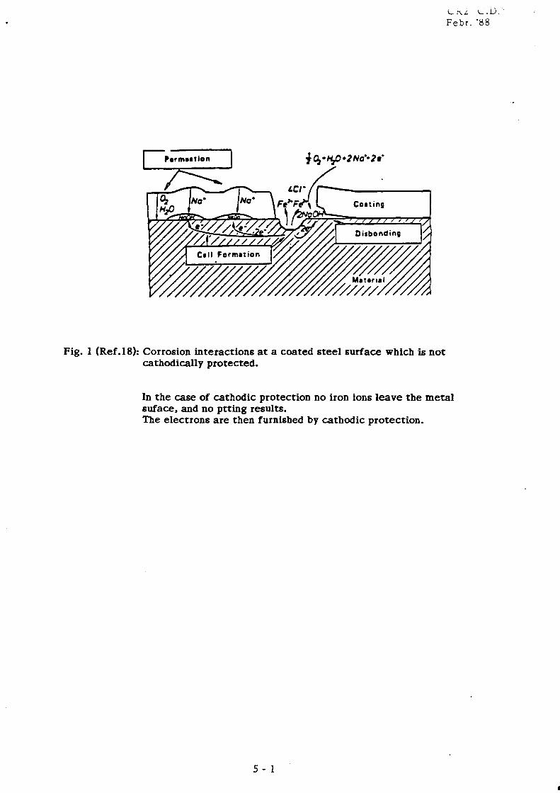
Figure 1 illustrates a corrosion cell at a coating holiday where the
following reactions occur:
At the anode, metal is consumed and iron ions are formed:
Fe ... Fe 2 + + 2e- (I)
At the cathode, hydroxide ions can be produced by the reduction of
oxygen
(II)
and normally to a negligible extent by the reduction of water
accompanied by hydrogen evaluation.
(Ill)
The hydroxide ions, produced at the cathode, are responsible for the
observed alkaline behaviour.
The electrons liberated in the anodic partial reaction I remain within
the bulk metal and migrate towards cathodic sites where electrons are
consumed by the cathodic partial reaction Ill.
c
COiling
Fig. 1 (Ref .18): Corrosion interactions at a coated steel surface which is not cathodically protected.
LI\.L L.U. Febr. '88
In the case of cathodic protection no iron ions leave the metal suface. and no ptting results. The electrons are then furnisbed by cathodic protection.
5 - 1
III
...
Reactio~s I a~d 11 depend on each other anc need to proceed in ba~ance
as fo11o .... s:
If the electrons released in reaction I are not consumed by reaction
11 the surface is polarised to a potential negative enough to stop
reaction I.
The anodic partial reaction I, ie "oxidation", and the cathodic
____ ---J:p-.,ti..?-.1 re?_cti..9.D.. U ... _j_e~liduC:j:~~u_~tain each otheLt-_Tbe_a5:c§.s.s_
of oxygen to a place where it may be reduced, controls the progress of
the actual corrosion reaction I.
It can be shown that in a corrosion cell developing on a steel surface I
exposed by coating damage, the edge of the holiday acts as the
cathode, whereas the anode is stabilised in the centre*). If the
coating is electrically conductive, and allows the migration of
ions and permeation of water/oxygen, the coated area near the holiday
can act as a cathode and as a consequence of ion migration and
eletrosmosis this area of the coating may develop blisters.
The destruction of adhesion due to alkaline moisture creeping under
the coating, starting from the edge of the holiday is symbolised in
the right hand section of figure 1 (most coatings do not bend up this
way, so disbonding may remain undetected).
*) This can be demonstrated as follows:
Dissolve ~ 1 g NeCl and ~ 30 mg K3 [Fe(CN),J in 20 ml water and add
two droplets 1% - phenolphthalein solution.
Remove about 1 cm 1 of coating from a coated steel surface without
loosening the edge of the remaining coating and fill the defect with
the above solution. After about 15 minutes xhe central parts of the
liquid turns blue, indicating the dissolution of iron (anode), ~~ils:
the edge of the droplet turns red, indicating the formation of 2~~~:i
(cathode).
With cathodic prctection, (C?), ie artificial negative polarisation of
the steel to UCu/CuSO. ~ -0.85 V* enough electrons are furnished
for the consumption of all the available oxyge~ in reaction 11 and
almost totally eliminating reaction I. Lowering the potential
promotes reaction Ill, which may become dominant. (At
UCu/CUSO. ~ -1.15 V hydrogen evolution can be observed.)
Experiments show that cathodic polarisation per se does not
form strong, soluble alkalis such as the alkali metals and barium must
be present. Apparently the cathodically produced strongly alkaline
reaction enables moisture to creep under the coatings. With ammonium
and calcium cations CD is markedly slower.
Cathodic polarisation in acid solutions does not usually lead to
disbonding.
It is observed that:
1. Alkali metal hydroxide solutions remove coatings from steel even
where cathodic polarisation is not applied.
2. Increased Alkalinity lowers the surface tension of water
appreciably.
3. In tests on PE coatings, lowering the surface tension of water by
a non-ionic surfactant may enable it to creep under the coating.
Although these observations lead to the supposition that CD is mainly
a matter of surface tension, chemical sensitivity of certain coating
materials to strong alkali may also be important. The widespread
assumption that cathodically formed H2 -gas lifts the coating and thus
*) the potential measured without IR drop, ~e 'off' potential in CP
measu:-ements
7
...
(
causes cathodic disbonding, no longer seems valid for two reasons,
viz.
1. CD occurs at negative potentia1s, even where hydrogen is not
discharged.
2. A negative potential which is sufficient to discharge H2 will not
extend into the liquid under a tightly fitting coating.
------------. -_ .. _- ------Thus, cathodic disbonding may be considered a type of alkaline
cleaning of the metal surface.
In all of these cases, including CD, adhesion loss is a consequence of I
the appearance of new phases below the coating; a previous lack of
adhesion, even at "points", is not a precondition for these to form or
migrate. The strength of adhesion and mechanical properties of the
coating itself may, however, influence the ease or velocity with which
these processes take place.
3. TEST METHODS FOR CATHODIC DISBONDING OF PIPE COATINGS
One of the first test methods for studying cathodic disbonding of pipe
coatings was the ASTM G8 method" published in 1968 as a tentative method,
and in 1972 as a standard test method.
The method standardises sample size, defect size, immersed area,
electrolyte, potential against a reference electrode, the duration of the
test-period, and procedures for measuring current demand and disbanded
area. The latest revision (1985) is more specific in temperature of
testing (23 ± 2°C instead of 20 to 30°C), and allows a sacrifical
magnesium anode, as an alternative to the use of an impressed current
system.
The repeatability quoted in G8-SS is lower than that in the previous
version, and is given as maximum 6 mm difference between duplicate results
of disbanding (Ar) on two specimens, taken from the same coated pipe from
commercial production.
e
The ASTM G8 method is meant as an accelerated procedure, for comparing one
coating with another. Paragraph 4 "Significance and Use" explains that
disbondment in this test is not necessarily an adverse indication of
performance. All pipeline coating now in common use will disbond to some
degree, but the same measured disbondment for two different coating systems
may not represent equivalent loss of corrosion protection.
A similar method, often used in Europe, is the British Gas CW/6 cathodic
__ disbondi.!!.S_met:.hod, on which the British .st~ndard BS 39 00 Fll (1985) _?:_, _ based.
It does not differ basically from the ASTH GB but; sample size and
electrolyte are different, and only an impressed current system is I
prescribed.
There are many variations of these two standards in existence which specify
particular requirements of individual end-users. The most important
differences concern the time of testing, temperature and potential.
Since the introduction of the ASTM G8 method, many investigations have been
made to evaluate the influence of the various test conditions and to study
the mechanism of cathodic disbonding.
3.1 Effect of Various Test Parameters
The effect of the various test-parameters on cathodic disbonding can
be summarised as follows:
3.1.1 Effect of Test Duration
In ref (6) various industrial pipe coating samples have been
tested using the ASTM G8 method with a potential .of -1.0 V for
periods up to 1 year.
This work showed that after about 6 months, the rate of
disbonding decreased and its extent levelled off to a constant
value after about 1 year.
-
The maximuTl, disbonding .. as about 40-50 mm for a PE coating and
about 60mm for bitumen coated samples. Other investigations
ho .. ever, sho .. disbonding of bitumen coatings at levels much less
than 60mm.
3.1.2 Effect of Potential
Cathodic disbonding tests at potentials bet .. een -0.85V and -1.2V
________ -=s:.:.;h,."o:...:;w-=e-=d:....-=that the disbondment increased wh€'O' the potential_ was __________ _
lowered from -0.85 to -1.2V (4).
Decreasing the potential from -1.5 V to -3.0 V does not result in
an increase of disbondment, although Hzgas evolution increases.
Apparently, at lower potentials more hydroxide ions are formed,
but below ca. -1.2V, due to hydrogen evolution, the increased
turbulence of the electrolyte prevents a further increase in
alkalinity. Within very small holidays gas bubbles can prevent
the flow of current, thus reducing electrochemical activity.
3.1.3 Effect of the Electrolyte
For cathodic disbondment to occur it is necessary that the
electrolyte is strongly alkaline at the steel surface. This can
only develop if alkali-ions are present for balancing the
hydroxyl ions formed at the steel surface. If no alkali-ions are
represent (eg if ZnC1 2 is used instead of NaCl) , virtually no
cathodic disbondment occurs (9).
3.1.4 Effect of Defect Size
Laboratory experiments by Heim et al (6) showed, that the rate of
disbonding is markedly influenced by the size of the defect when
thick coatings (PE Bitumen) are tested.
With a 100mm2 hole in the coating, the disbonding level (measured
in mm radius extension or "under creepage"), was 4 times greater
than with a 1 mm 2 hole.
10
Thinner coatings such as FBE-coating however. showed no
difference when the defect size was changed from 1 to 11 mm
diameter, with the disbonding rates being only very small «5mm
after 1 year).
3.1.5 Effect of Polarization Current
In the course of cathodic disbonding testing at 25 DC and at a ____ -=c..=onstant vol taE,!! the ele("'~rical current does not sj,gnHiq.nJ:J.Y _________ _
change (17) with time, provided the coating does not
disintegrate. With the presently known factory applied coatings,
signs of deterioration or blistering are unusual. In disbonded
areas the coating normally rests close to the steel surface with I
only a thin film of moisture in between and extended current
carrying capacity is low.
3.1.6 Effect of Temperature on Cathodic Disbonding
The temperature of testing has a strong effect on the rate of
cathodic disbonding. as it has on mechanical properties and on
other properties such as water absorption and electrical
conductivity.
Only a few systematic investigations have been carried out on the
maximum service temperature of coatings in relation to properties
such as electrical resistivity. blistering and cathodic
disbondment.
At the BHRA-conference 1981 (report hI) results of cathodic
disbonding tests and electrical resistivity tests were published.
Various coatings such as coal tar-epoxy., coal tar-polyurethane,
liquid and powder epoxy, polyethylene and polyamide were first
subjected in stage 1 to a blistering test (immersion of coated
pipe samples in an electrolyte at 70 D C, with no defects in the
coatings and with a cathodic protection potential of -1.5V).
In stage 2. after making an artificial holiday in the coat inK.
11
III
-
testing was continued for cathodic disbonding at 70 0 e on the same
piece of coated pipe.
The results of this work showed, that in stage 1, blistering
occurred on most coatings with a specific electrical resistivity
of < 10" ohm m2 •
After stage 2 (cathodic disbonding test at 70 0 e) all coatings
_________ we~~Q!DPletel_Y_cl,isJ2..o_ndeLanu_Qme samples developed blis_ter_s ...... _____ _
Examination of the blisters showed their contents to be alkaline
with a pH of 12.5.
A similar series of tests, but with an electrolyte with less
sodium chloride, resulted in much less cathodic disbondment, but
again in this series many samples showed blistering in stage 2,
or signs of deterioration (swelling). The lower level of
cathodic disbondment can be explained by the reduced
concentration of the strong alkali-forming cations Na+ or K+.
The formation of blisters in stage 1 and stage 2, can be
explained by electro-osmosis and water-permeation, accelerated by
higher temperatures.
3.2 Cathodic Disbonding Test-Reguirements
Many standards and specifications specify a C.D. test method and also
a maximum level of disbonding.
In Table 3 a selection of these requirements is given for epoxy
coatings and for polyethylene coatings.
The table shows, that there is a large variation in test duration,
temperature of testing and in maximum accepted disbondment value.
The fact, that some companies require one test to be carried out per
100 pipes, (which can mean one test per day production) makes it
obvious that there is a lot of misconception in the applicability.of
12
TABLE 3: VARIOUS C.O. TEST REQUIREMENTS
Specification Basic Tfst Time Temperature Specified Value Method 1) (days) oC) 2)
'. A) E2ox"r Coatings:
HEN 6905 (Dutch Standa rd) G8 90 20-30 max. 20 mm
British Gas PS/CW6 CW6 28 20 max. 5mm
DIN 30671 (draf nov'S3) CW6 30 23 max. 10 ~ 2 65 max. 15 mm
6.1 Cathodic disbonding tests can give some information about the
sensitivity of coatings to alkaline conditions, produced during
cathodic protection.
6.2 It gives no information about the maximum rate and level of
cathodic disbonding, that can occur around a defect under field
conditions.
6.3 If different types of coatings are compared, a lower rate of
disbondment for one type of coating in a C.D. test does not
necessarily mean a better performance in practice.
6.4 C.D. testing may be used in a comparative way, to study similar
types of coatings, or to optimise application parameters, but not as a
quality control test.
6.5 Cathodic disbondment does not necessarily result in a loss of
general corrosion protection, provided that the coating does not
disintegrate in the caustic environment resulting from cathodic
protection (Ref. DIN).
6.6 Cathodic disbonding is only one of many factors which lead to
stress corrosion cracking. If specific conditions of stress,
temperature and environment are not achieved stress corrosion cracking
will not occur even though a coating may be cathodically disbonded.
17
6.7 To study the sensitivity to the occurrence of cathodic
blistering, it is likely that C.D. testing should be extended beyond
one month. Additionally the electrical coating resistance should be
measured, to provide information on the corrosion prevention
properties of a coating.
6.8 For a suitable test procedure, the following parameters are
suggested.
Duration 1 month minimum
Temperature room temperature
Potential -1.5V (vs s~t.CU/CUS04)' impressed current
Electrolyte 1% each NaCl/Na1SO./Na1CO l in distilled water I
Anode Pt-wire, or platinised titanium
Exposed surface: ca 50 cm 1 (cell of approximately 8 cm 0 sealed onto
the surface of sample).
Defect size
Current
6 mm, minimum
Provision made for measuring current.
18
-CR2"C.D."
Collected Literature and References
1. S.H. Alexander, Variables that influence cathodic disbonding test results, Procedings Nace Conference 1969, vol. 25, plS1.
2. Dr. W. Schwenk, The importance of adhesion of thick coatings on corrosion protection of pipelines, 3R-International, vol.1, 1973, pIS.
3. W. Takens, J. v. Helden, A. Schrik, Corrosion behaviour of steel gas pipelines with a PE-coating, Gas, April 1973, p174.
4. Technical Committee, Resurvey of methods of disbonding resistance of organic coatings, Technology, vol. 47, May 1975, p57
evaluating cathodic Journal of Paint
5. P. Pickelmann, Haftungsverlust und Unterrostung von PE-Stahlrohrumhullungen. gwf-gas/erdgas 116 (1975) vol 6, p229.
6. G. Heim, W. v. Baeckmann, D. Funk, Investigating subsurface creepage of coverings of steel pipe subject to cathodic polarization, 3RInternaitonal, April 1975, vol 2, p111.
7. W. Schwenk, Studies into the effect of cathodic polarization on protective coatings, 3R international, vol 7, 1976, p389.
8. W. Domalski, E. Gemmer, The behaviour of organic anti-corrosive coatings applied to steel pipes in a combined stress disbonding test, 3R-International vol 6, 1977 p319.
9. W. Schwenk, Einflussgrossen der Unterwanderung von Beschichtungen fur den Korrosionsschutz von Rohrleitungen und Ihre technische Bedeutung, gwf-gas/erdgas, 1977, vol 1, p7.
10. W. von Baeckmann, N. Schmitz-Pranghe, W. experience with polyethylene coated steel protection, paper J.1, sec. intern, conf. protection of pipe, September 1988, BHRA.
Schwenk, Progress and pipeline with cathodic on internal and external
11. A.C. Toncre and H. Ahmed, Cathodic protection in crevices under disbonded coatings, paper 161, NACE-Corrosion/78.
12. E. Senkowski, Standard laboratory tests for pipeline coatings, paper 69, NACE-Corrosion/78 Proceedings.
13. W. Schwenk, Interaction between pipe coating and cathodic corrosion protection, 3R-International, Aug./Sept. 1979, vol 8/9, p565.
14. G.M. Harris, A review of recent developments and the performance of tape coatings for underground pipelines, NACE Corrosion/77, paper 145.
15. J.C. Thompson, B.A. Wallace, S.L. Simpson, Testing of coatings for elevated temperature pipeline, NACE-Corrosion/79, paper 214.
16. W. van Baeckmann, W. Schwenk, Handbuck des Kathodischen Korrosionschutzes Verlag Chemie, 1980.
17. W. Schwenk, Requirements on coating materials for corrosion protection of pipes, 3R-international, 1980, vol 10, p586.
18. W. Schwenk, Adhesion loss of organic coatings, causes and consequences for corrosion protection, reprint form Corrosion Control by organic coatings, p103.
20. M. Pollard, Study of disbonding phenomena of organic pipe coatings, internal report of GdF-DETN., Gaz de France.
21. B.A. Wallace, J.C. Thompsom, State of the art test methods for evaluating pipeline coatings, NACE-Corrosion/82, paper 119.
22. P. Pickelmann, H. Hildebrand, Zur Unterrostung von RohrumhallungenErgebnisse von Feldversuchen, gwf-gas/erdgas , 1981, vol 2, p54.
23. W. Schwenk, The significance of protection current demand for the length of cathodic protection range of long distance pipelines, 3RInternational, Sept. 1981, vol 9, p466.
24. A.C. Toncre, The relation of coatings and cathodic protection for underground corrosion control, Underground Corrosion, ASTM STP 741, 1981, p166.
25. W. Schwenk, Arten der Korrosion und Korrosionsschutzmassnehmen bei erdverlegten Rohrleitungen aus Stahl, gwf-gas/erdgas, 1982, vol 4, p158.
26. H. Heidheiser, W. Wang, L. Igetoft, The mechanism for the cathodic delamination of organic coatings form a metal surface, Progress in Organic Coatings nr. 11 (1983), p19.
28. B. Husock, R. Wilson, Potentials and hydrogen evolution on coated pipe, NACE-CORROSION/83, paper 291.
29. R.T. Bell, Fusion Bonded Epoxy, what constitute a failure, NACECORROSION/83, paper 111.
30. w. Schwenk, Current distribution during the electro-chemical corrosion protection of pipes, Corrosion Science, vol 23, no. 8, p871 (1983).
jiiIII'
31. Y. Schwenk, Some aspects solutions and associated Korrosion 34 (1983) p287.
of the corroison of iron in alkaline fundamental questions, Yerkstoffe und
32. E. Monti, Cathodic disbonding test on pipeline coatlngs, jan. '84 (SNAM-R&D report).
33. L. Egetoft, Cathodic delamination of organic coatings Proceedings vol 1, 9th Scandinavian Corrosion Congress, September 1983. p185.
on steel, Copenhagen,
34. A.C. Toncre, On achieving polarization beneath unbonded pipe coatings, Materials Performance August 1984, p22.
35. Y. Yelbech, A. Engel, D. Muller, R. Sporl, W. Schwenk, Protection of high-pressure steelpipelines for the transmission of gas against stress corrosion crackig at high temperatures. Werkstoffe und Korrosion 37, (1986) p. 176.
36. E.L. K6hler, The mechanism of cathodic disbondment of protective organic coatings-aqueous displacement of elevated pH NACE-CORROSION, vol. 40, no. 1, Jan. 1984, p.5.
37. ASTM-98-85. Standard Test methods for cathodic disbonding of pipeline coatings.
38. BS 3900: Part F 11: 1985. Determination of resistance to cathodic disbonding of coatings for use on land-based buried structures, British Standard Methods of test for paints.
39. DIN 50 928, sept. 1985, Corrosion of metals: testing and assesment of the corrosion protection of coated metallic materials under corrosive action by aqueous media.
40. DIN 30670, July 1980, Polyethylene coatings of steel tubes, fittings and matching pieces, p.7, Erlauterungen.
41. 5th symposium on line pipe research, Houston 1974, A.G.A., Catalogue no. L, 30174, Paper T.
42. World Gas Conference Toronto 1979, Committee C, theme 6 "Inter crystalline stress corrosion in high pressure gas transmission pipelines at high working temperatures downstream of compressor stations", questionnaire.


![cathodic protection in practise · 2 [CATHODIC PROTECTION/BM] CATHODIC PROTECTION P E FRANCIS 1 INTRODUCTION The first practical use of cathodic protection is generally credited to](https://static.documents.pub/doc/80x56/5ace93c87f8b9ae2138b87e4/cathodic-protection-in-cathodic-protectionbm-cathodic-protection-p-e-francis.jpg)


