66
• Part I, Status of CEPC Accelerator (Physics) Study • Part II, Multi-Objective Optimization with possible application in SuperKEKB
• Part I, Status of CEPC Accelerator (Physics) Study
• Part II, Multi-Objective Optimization with possible application in SuperKEKB

Status of CEPC Accelerator (Physics) StudyYuan Zhang for CEPC Accelerator Team
Institute of High Energy Physics, Beijing
KEK Mar, 2016

What is a (CEPC + SppC) (Q. Qin)
• Circular Higgs factory (phase I) + super pp collider (phase II) in the same tunnel
ee+ Higgs Factory
pp collider
3

4
CE P C -S P P C P r elim in a r y Con cep tu a l D esign R ep or t
March 2015
The CEPC-SPPC Study Group
Armen Apyan13, Lifeng Bai12 (白利锋), Mei Bai45 (柏梅), Sha Bai1 (白莎),
Paolo Bartalini 28, Sergey Belomestnykh14, Tianjian Bian1 (边天剑),
Xiaojuan Bian1 (边晓娟), Wenyong Cai8 (蔡文勇), Yunhai Cai15 (蔡云海),
Jianshe Cao1 (曹建社), Weiping Chai2 (柴伟平), Ningbo Chang28 (畅宁波),
Fuqing Chen1 (陈福庆), Geng Chen4 (陈耿), Jiaxin Chen1 (陈佳鑫),
Fusan Chen1 (陈福三), Shiyong Chen28 (陈时勇), Xiaonian Chen8 (陈晓年),
Xurong Chen2 (陈旭荣), Gang Chen1 (陈刚), Jian Cheng1 (程健), Yunlong Chi1 (池云龙),
Weiren Chou16 (周为仁), Xiaohao Cui1 (崔小昊), Changdong Deng1 (邓昌东),
Qingyong Deng1 (邓庆勇), Weitian Deng29 (邓维天), Hengtong Ding28 (丁亨通),
Yadong Ding1 (丁亚东), Haiyi Dong1 (董海义), Jiajia Dong8 (董甲甲),
Lan Dong1 (董岚), Yuhui Dong1 (董宇辉), Zhe Duan1 (段哲), Jingzhou Fan5 (范荆洲),
Junjie Fan34 (范俊杰), Yoshihiro Funakoshi21 (船越义裕), yonggui Gao46 (高勇贵),
Pingping Gan4 (甘娉娉), Jie Gao1 (高杰), Yuanning Gao5 (高原宁),
Huiping Geng1 (耿会平), Dianjun Gong1 (宫殿军), Li Gong46 (龚丽),
Lingling Gong1 (龚玲玲), Alfred Goshaw26, Chen Gu5 (顾晨), Lili Guo8 (郭莉莉),
Yan Guo47 (郭雁), Yuanyuan Guo1 (郭媛媛), Ramesh Gupta14 (古拉梅),
300 authors from 57 institutions
in 9 countries

5
International Review (Feb 14-16, 2015)
1. The Committee considers the CEPC-SPPC to be well aligned with the future of
China’s HEP program, and in fact the future of the global HEP program.
2. The design goals are well defined and comprehensive. We provided remarks and
recommendations to improve the design, but we definitely consider this design
to be credible and with sufficiently conservative assumptions.
3. The great majority of the accelerator physics issues are adequately addressed,
and after addressing our recommendations, we expect that all the accelerator
physics issues would be adequately addressed.
4. The designs of the technical systems and conventional facilities are effective for
achieving the performance goals.
5. We find the CEPC design compatible with the future upgrade to the SPPC.
6. Technical risks and their potential impact were presented together with
mitigation measures, while in some cases more study and R&D are needed.
7. The R&D program is clearly defined, and while we recommended a few
additional R&D items, the program is adequate. We further believe that this
R&D program will be highly beneficial to the science and technology
infrastructure in China and will contribute to its economy.
8. We made a few suggestions for improvements of the design.
International Review Committee Members:
Ralph Assmann, DESY (Germany)
Ilan Ben-Zvi, BNL (USA)
Marica Biagini, INFN (Italy)
Mike Koratzinos, CERN/U. Geneva (Switzerland)
Eugene Levichev, BINP (Russia)
Katsunobu Oide (Chair), KEK (Japan)
Bob Rimmer, JLab (USA)
John Seeman, SLAC (USA)
Zhentang Zhao, SSRC (China)
Committee’s response to the charges:
Committee wrote a 17-page detailed report.

CEPC-SPPC Timeline (preliminary)
6CEPC-SPPC Meeting, May 17-18, 2015W. Chou
R&D
Engineering Design
(2016-2020)
Construction
(2021-2027)
Data taking
(2028-2035)
Pre-studies
(2013-2015)
1st Milestone: Pre-CDR (by the end of 2014) → R&D funding request to Chinese government in 2015
(China’s 13th Five-Year Plan 2016-2020)
CEPC
R&D
(2014-2030)
Engineering Design
(2030-2035)
Construction
(2035-2042)
Data taking
(2042-2055)
SPPC
2nd Milestone: 13th Five Year Plan R&D

CEPC Design – Top Level Parameters
7
Parameter Design Goal
Particles e+, e-
Center of mass energy 240 GeV
Integrated luminosity (per IP per year) 250 fb-1
No. of IPs 2
SPPC Design – Top Level Parameters
Parameter Design Goal
Particles p, p
Center of mass energy 70 TeV
Integrated luminosity (per IP per year) (TBD)
No. of IPs 2
one million Higgs from 2 IPs in 10 years
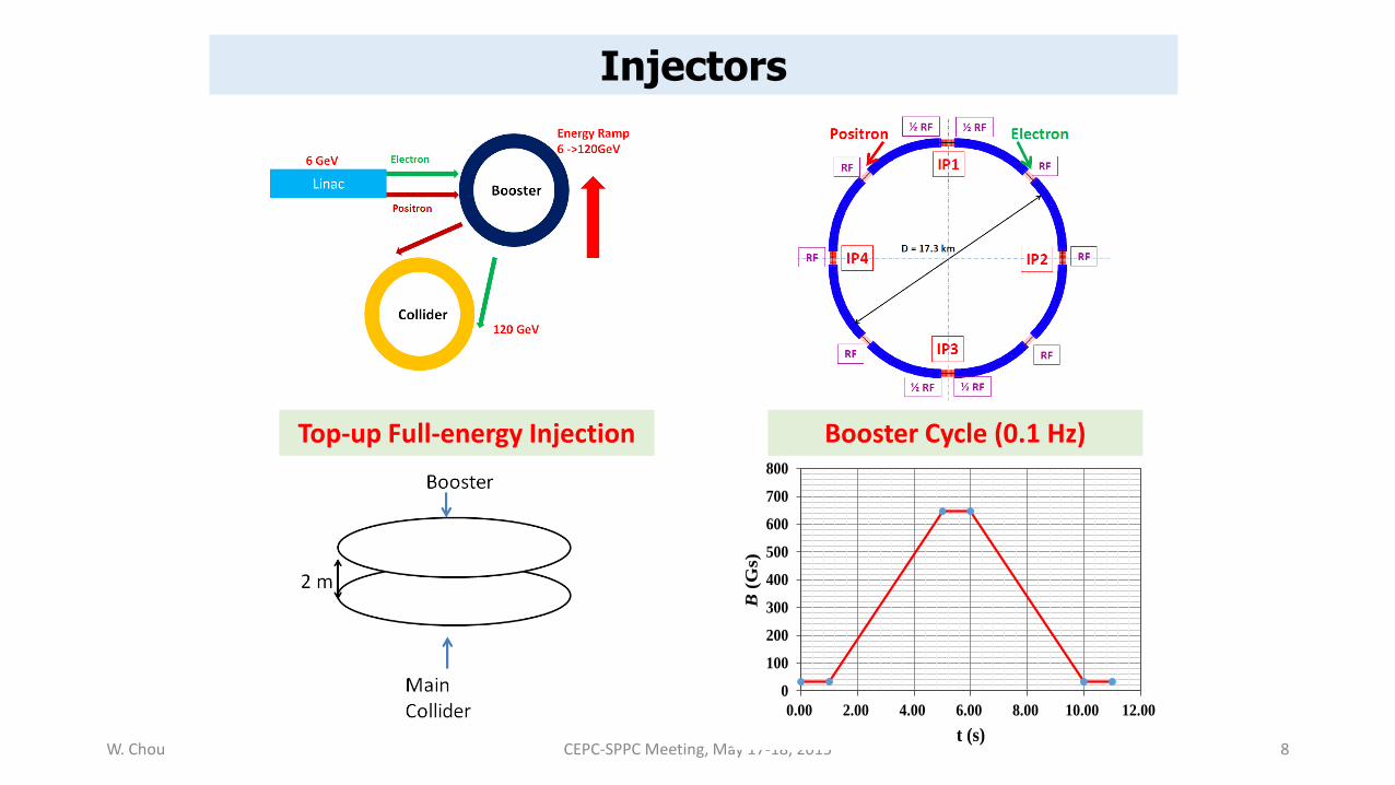
Injectors
W. Chou CEPC-SPPC Meeting, May 17-18, 2015 8
0
100
200
300
400
500
600
700
800
0.00 2.00 4.00 6.00 8.00 10.00 12.00
B(G
s)t (s)
Booster Cycle (0.1 Hz)Top-up Full-energy Injection

CEPC Lattice Layout (September 24, 2014)
P.S.
P.S.
P.S.
IP1
IP4
IP3
IP2D = 17.3 km
½ RF
RF
RF
RF
RF
½ RF
½ RF
½ RF
RF RF
One RF station: • 650 MHz five-cell
SRF cavities;• 4 cavities/module• 12 modules, 10 m
each• RF length 120 m
4 IPs, 1038.4 m (944 m) each
4 straights, 849.6 m (944 m) each
8 arcs, 5852.8 m each
C = 54.374 km
9

CEPC Design – Main Parameters
Parameter Unit Value Parameter Unit Value
Beam energy [E] GeV 120 Circumference [C] m 54752
Number of IP[NIP] 2 SR loss/turn [U0] GeV 3.11
Bunch number/beam[nB] 50 (48) Bunch population [Ne] 3.79E+11
SR power/beam [P] MW 51.7 Beam current [I] mA 16.6
Bending radius [r] m 6094 momentum compaction factor [ap] 3.36E-05
Revolution period [T0] s 1.83E-04 Revolution frequency [f0] Hz 5475.46
emittance (x/y) nm 6.12/0.018 bIP(x/y) mm 800/1.2 (3)
Transverse size (x/y) mm 69.97/0.15 xx,y/IP 0.118/0.083
Bunch length SR [ss.SR] mm 2.14 Bunch length total [ss.tot] mm 2.65
Lifetime due to Beamstrahlung min 47lifetime due to radiative Bhabhascattering [tL]
min 51
RF voltage [Vrf] GV 6.87 RF frequency [frf] MHz 650
Harmonic number [h] 118800 Synchrotron oscillation tune [ns] 0.18
Energy acceptance RF [h] % 5.99 Damping partition number [Je] 2
Energy spread SR [sd.SR] % 0.132 Energy spread BS [sd.BS] % 0.096
Energy spread total [sd.tot] % 0.163 ng 0.23
Transverse damping time [nx] turns 78 Longitudinal damping time [ne] turns 39
Hourglass factor Fh 0.68 Luminosity /IP[L] cm-2s-1 2.04E+34
W. Chou CEPC-SPPC Meeting, May 17-18, 2015 10
11
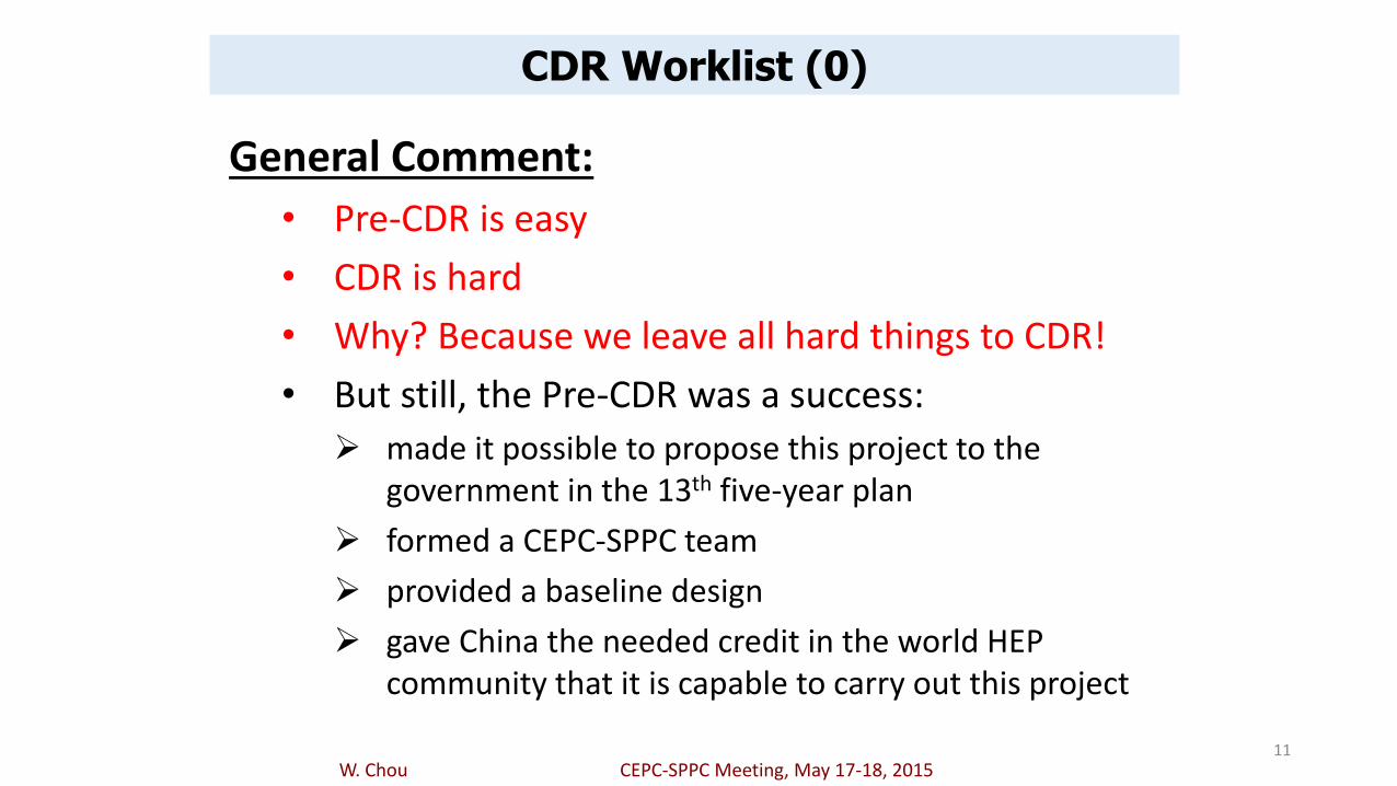
CDR Worklist (0)
General Comment:
• Pre-CDR is easy
• CDR is hard
• Why? Because we leave all hard things to CDR!
• But still, the Pre-CDR was a success:
made it possible to propose this project to the government in the 13th five-year plan
formed a CEPC-SPPC team
provided a baseline design
gave China the needed credit in the world HEP community that it is capable to carry out this project
W. Chou CEPC-SPPC Meeting, May 17-18, 2015

12
CDR Worklist (3)
5. Dynamic aperture for L*= 1.5m, βy*= 3mm
6. Pretzel scheme:
to complete a consistent design including beam orbit/optics in the arcs and IRs, dynamic aperture, beam-beam, beam injection, etc.
7. Investigating alternative designs:
W. Chou CEPC-SPPC Meeting, May 17-18, 2015
13
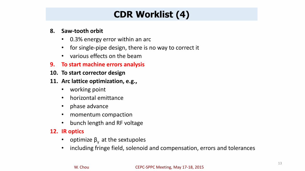
CDR Worklist (4)
8. Saw-tooth orbit
• 0.3% energy error within an arc
• for single-pipe design, there is no way to correct it
• various effects on the beam
9. To start machine errors analysis
10. To start corrector design
11. Arc lattice optimization, e.g.,
• working point
• horizontal emittance
• phase advance
• momentum compaction
• bunch length and RF voltage
12. IR optics
• optimize βy at the sextupoles
• including fringe field, solenoid and compensation, errors and tolerances
W. Chou CEPC-SPPC Meeting, May 17-18, 2015

14
CDR Worklist (5)
13. Beam-beam effect:
• to study beam-beam from parasitic crossing
• this is especially important in Z operation due to large number of crossings
• compensation method
Momentum acceptance vs. Beam lifetime
Luminosity vs. Beta*
W. Chou CEPC-SPPC Meeting, May 17-18, 2015

15
CDR Worklist (6)
14. To establish an emittance budget
• from source to linac to Booster to collider
• including machine imperfection and allowance, optics mismatch and energy errors
15. To establish a geometric aperture model for the collider
• including the injection region, beam dump region, doublet, maximum beta area
16. Machine-detector interface (MDI)
• radiation shielding design
• simulation using Sullivan’s code
• collimator design
W. Chou CEPC-SPPC Meeting, May 17-18, 2015

16
CDR Worklist (7)
17. Beam instability
• to establish a realistic impedance model instead of scaling from KEKB or LEP, including separators, collimators, ferrite damper in RF, etc.
• Banana effect due to transverse wake from off-center orbit
• to study instabilities at Z-pole, which has lower energy and higher beam current
• feedback system design
18. Orbit stability
• not covered in the Pre-CDR but should be in the CDR
19. Polarization
• not included for Higgs operation
• but may be needed for Z operation
• even for Higgs, we may need it for energy calibration
• to investigate the options (e.g., Gai Wei’s scheme)

17
CDR Worklist (8)
20. Source and linac
• a complete simulation for e+ beam: from the e- beam to target to capture to transport line to re-injection into the linac to acceleration to injection into the Booster
• If the requirement of 3 nC, 0.3 mm-mrad cannot be met, then a damping ring is needed in the CDR
• e+ beam return line design
• SLAC has offered us a 15 GeV linac including klystrons as well as two damping rings. We need a decision about whether we will take the offer. If yes, when and how.
• to include the study for Z operation, which needs higher beam current
21. Booster
• to mitigate low field injection problem: earth field shielding, to add SLAC’s linac, to add a pre-Booster
• To study saw-tooth effect, vacuum pipe, eddy current, machine imperfection, correctors, etc.
W. Chou CEPC-SPPC Meeting, May 17-18, 2015

Pretzel Scheme

After adding pretzel orbit (with correction) :
Solution need to be improved….
GENG Huiping

Main output parameters:
Was 3012MV
Was 1.0
Was 6.28nm
GENG Huiping


Beam Tilt Estimation
)(10*16.1 4max mX
)(10*7.0)(97.69 -4 mmx ms
SUN Yuansheng

Interaction Region
Yiwei Wang 24
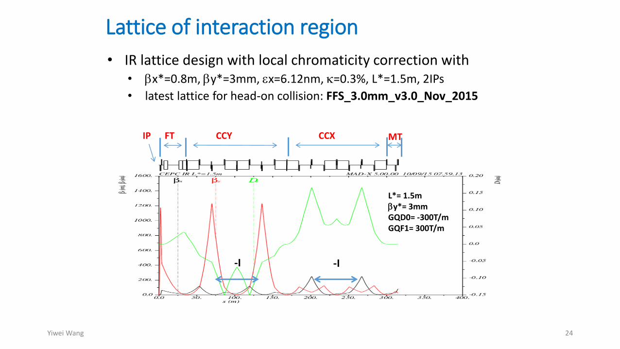
Lattice of interaction region
• IR lattice design with local chromaticity correction with• bx*=0.8m, by*=3mm, ex=6.12nm, =0.3%, L*=1.5m, 2IPs
• latest lattice for head-on collision: FFS_3.0mm_v3.0_Nov_2015
L*= 1.5mby*= 3mmGQD0= -300T/mGQF1= 300T/m
-I -I
IP FT CCY CCX MT
Yiwei Wang 13 Nov 2015 25
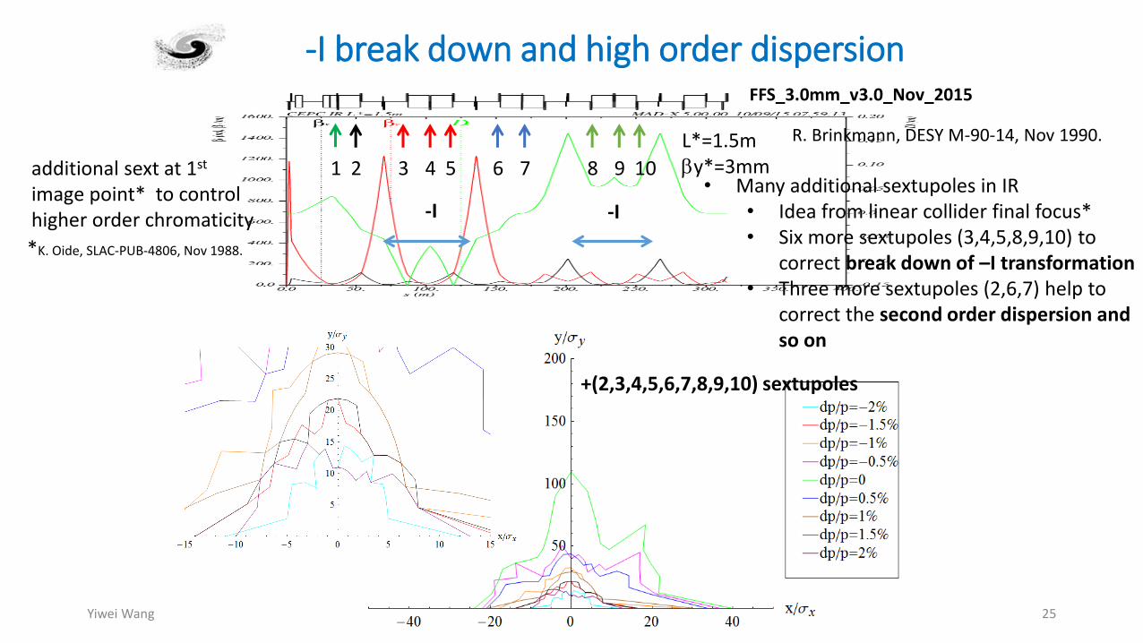
-I break down and high order dispersion
-I -I
1 2 3 4 5 6 7 8 9 10
FFS_3.0mm_v3.0_Nov_2015
L*=1.5mby*=3mm
+(2,3,4,5,6,7,8,9,10) sextupoles
additional sext at 1st
image point* to control higher order chromaticity
*K. Oide, SLAC-PUB-4806, Nov 1988.
• Many additional sextupoles in IR• Idea from linear collider final focus*• Six more sextupoles (3,4,5,8,9,10) to
correct break down of –I transformation• Three more sextupoles (2,6,7) help to
correct the second order dispersion and so on
R. Brinkmann, DESY M-90-14, Nov 1990.

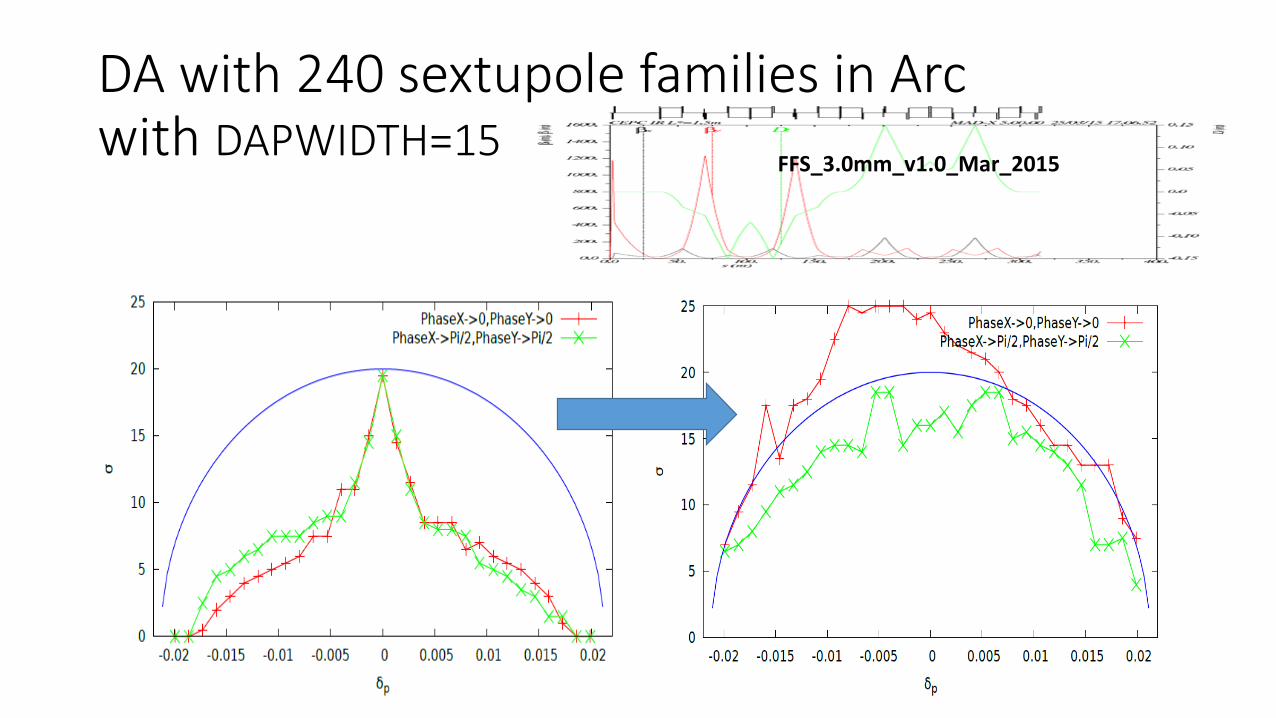
FFS_3.0mm_v1.0_Mar_2015
DA with 240 sextupole families in Arcwith DAPWIDTH=15


Partial Double Ring

THE ‘BOWTIE’ DESIGNby Michael Koratzinos (University of Geneva)
IPAC’15, MITIGATING PERFORMANCE LIMITATIONS OF SINGLE BEAM-PIPECIRCULAR e+e- COLLIDERS
A solution that can
accommodate O(1000) bunches
while keeping more than
90% of the ring with a single
beam pipe.

Primary parameter for CEPC double ring(wangdou20160219)
Pre-CDR H-high lumi. H-low power Z
Number of IPs 2 2 2 2
Energy (GeV) 120 120 120 45.5
Circumference (km) 54 54 54 54
SR loss/turn (GeV) 3.1 2.96 2.96 0.062
Half crossing angle (mrad) 0 14.5 15 11.5 15 15
Piwinski angle 0 2 2.5 2 2.6 8.5
Ne/bunch (1011) 3.79 3.79 2.85 2.81 2.67 0.46
Bunch number 50 50 67 40 44 1100
Beam current (mA) 16.6 16.9 16.9 10.1 10.5 45.4
SR power /beam (MW) 51.7 50 50 30 31.2 2.8
Bending radius (km) 6.1 6.2 6.2 6.2 6.2 6.1
Momentum compaction (10-5) 3.4 3.0 2.5 2.6 2.2 3.5
bIP x/y (m) 0.8/0.0012 0.306/0.0012 0.25/0.00136 0.22/0.001 0.268 /0.00124 0.08/0.001Emittance x/y (nm) 6.12/0.018 3.34/0.01 2.45/0.0074 2.67/0.008 2.06 /0.0062 0.62/0.002Transverse sIP (um) 69.97/0.15 32/0.11 24.8/0.1 24.3/0.09 23.5/0.088 7/0.046
xx/IP 0.118 0.04 0.03 0.04 0.032 0.005
xy/IP 0.083 0.11 0.11 0.11 0.11 0.084
VRF (GV) 6.87 3.7 3.62 3.6 3.53 0.12
f RF (MHz) 650 650 650 650 650 650
Nature sz (mm) 2.14 3.3 3.1 3.2 3.0 3.9
Total sz (mm) 2.65 4.4 4.1 4.2 4.0 4.0
HOM power/cavity (kw) 3.6 3.3 2.2 1.5 1.3 0.99
Energy spread (%) 0.13 0.13 0.13 0.13 0.13 0.05
Energy acceptance (%) 2 2 2 2 2
Energy acceptance by RF (%) 6 2.2 2.2 2.2 2.1 1.1
ng 0.23 0.49 0.47 0.47 0.47 0.27
Life time due to
beamstrahlung_cal (minute)
47 53 36 41 32
F (hour glass) 0.68 0.73 0.82 0.69 0.81 0.95
Lmax/IP (1034cm-2s-1) 2.04 2.97 2.96 2.03 2.01 3.61

CEPC Partial Double Ring Layout
SU Feng
2016.2.18
IP1_ee
IP3_ee
IP2_ppIP4_pp
3.2Km
RF
1/2RF 1/2RF
1/2RF
RF
RF RF
1/2RF
IP1_ee/IP3_ee, 3.37Km
IP2_pp/IP4_pp, 892.8m
4 Short Straights, 141.6m?
4 Medium Straights, 466.4m
4 Long Straights, 892.8m
2 Short ARC, 24*FODO, 892.8m
4 Medium ARC, 132*FODO, 4910.4m
4 Long ARC, 144*FODO, 5356.8m
C=56145m
1/2RF 1/2RF
1/2RF 1/2RF
Bypass
about 43.89m
Bypass
about 43.89m
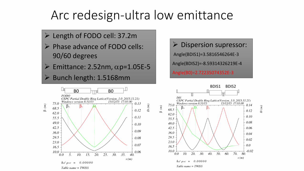
Arc redesign-ultra low emittance
Length of FODO cell: 37.2m
Phase advance of FODO cells: 90/60 degrees
Emittance: 2.52nm, ap=1.05E-5
Bunch length: 1.5168mmBDIS1 BDIS2
Dispersion supressor:Angle(BDIS1)=3.5816546264E-3
Angle(BDIS2)=-8.59314326219E-4
Angle(B0)=2.72235074352E-3
B0 B0

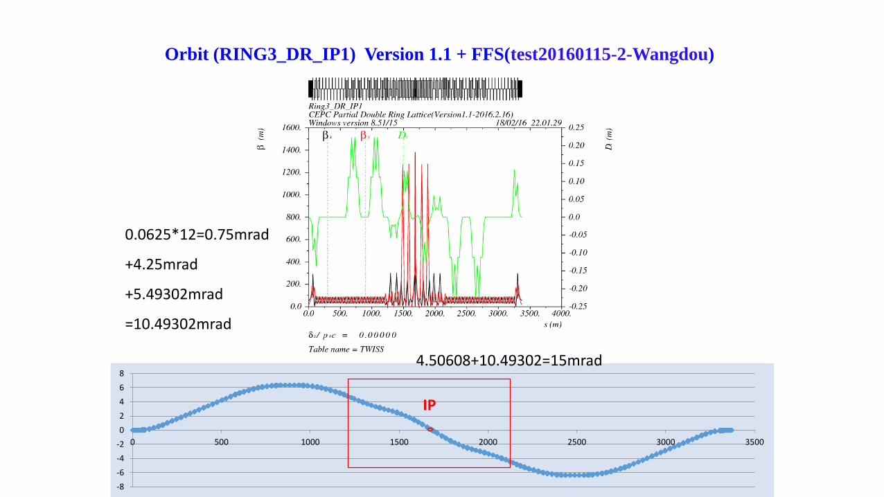
Orbit (RING3_DR_IP1) Version 1.1 + FFS(test20160115-2-Wangdou)
-8
-6
-4
-2
0
2
4
6
8
0 500 1000 1500 2000 2500 3000 3500
IP
0.0625*12=0.75mrad
+4.25mrad
+5.49302mrad
=10.49302mrad
4.50608+10.49302=15mrad
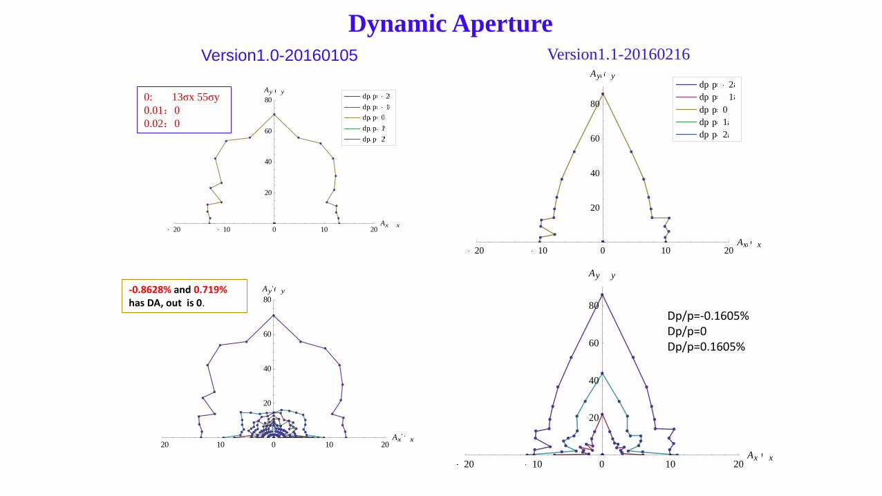
Dynamic Aperture
Version1.0-20160105
20 10 0 10 20Ax x
20
40
60
80
Ay y
dp p 2
dp p 1
dp p 0
dp p 1
dp p 2
20 10 0 10 20Ax x
20
40
60
80
Ay y-0.8628% and 0.719%has DA, out is 0.
0: 13σx 55σy
0.01:0
0.02:0
Version1.1-20160216
20 10 0 10 20Ax x
20
40
60
80
Ay y
dp p 2
dp p 1
dp p 0
dp p 1
dp p 2
20 10 0 10 20Ax x
20
40
60
80
Ay y
Dp/p=-0.1605%Dp/p=0Dp/p=0.1605%

Booster

47.2 meter FODO structure.
Non-interleaved sextupole scheme.
10 FODOs make up a cell to cancell off-momentum particle's beta beat
effect.
8 folds symmetry
16 families sextupole are used to cancell second order chromaticity.
DA of on-mumentum and off-mumentum are good enough for booster.
94.4 meter FODO structure is also trying
CEPC booster lattice
Tianjian Bian, Xiaohao Cui
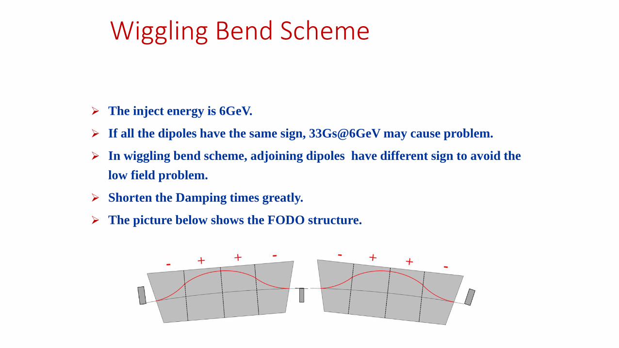
Wiggling Bend Scheme
The inject energy is 6GeV.
If all the dipoles have the same sign, 33Gs@6GeV may cause problem.
In wiggling bend scheme, adjoining dipoles have different sign to avoid the
low field problem.
Shorten the Damping times greatly.
The picture below shows the FODO structure.


Error

CEPC field error• The multipole errors in the main ring seems to have a large effect on the 2% off-momentum DA.
• The field errors in the FFS seems to have a large effect on the vertical on-momentum DA.
• With all B,Q,S multipole errors in CEPC whole ring including FFS, the 2% off-momentum DA reduced to about 1/3~1/2.
• With correctors and BPMs adding in the beam line, SAD hash table has no space. SAD can not deal with large ring.
Method 1: Optimization of DA (precondition: best DA without error)
orbit correction(for misalignment errors)
tune correction(for quad B*L error)
FMA analysis , add octupole, decapole, dodecapole…….
Method 2: Reduce errors (maybe high level requirement in magnet manufature)reduce the errors to the DA that we can accept
Although could be corrected in simulation, may not the case in real situation……
Cure DA
Sha Bai

MDI

MDI Status
• Develop MDIToolkit –uniform computing platform to established the environment for MDI study on IHEP computing cluster
• Background study: SR, Radiative Bhabha scattering, Beamstrahlung
• With 2cm aperture collimator, lost particles of radiative Bhabha and beamstrahlung in IR after several machine turns can be effectively prevented, but need to be optimized.
• SC magnets are designed preliminarily. Conceptual design and magnetic field calculation.
• Anti-solenoid design is optimizing, set up solenoid model in accelerator software.

Local double ring MDI layout
Detectors (including silicon tracker, vertex detector, TPC etc on….) which are “far” from this region, should be same as in the single ring.

Summary
• We’ve made much progress after pre-CDR.
• Many problems have been “touched”.
• All work should converge to a self-consistent design.
• It is urgent to finish the CDR in the end of 2016.

• This page is blank
Multi-Objective Optimization with possible application in
SuperKEKBY. Zhang and D. Zhou
Mar. 9th, 2016

Introduction
• This work was firstly excited by Oide’s talk.
K. Oide, “A design of beam optics for FCC-ee”, 2015-09
“255 sextupole pairs per half ring”
• Downhill Simplex is a local optimization algorithm
• We use a global optimization algorithm: Diffential Evolution (Suggested by Ji Qiang@LBNL)
• Other popular algorithm: Genetic Algorithm, Particle Swarm

Differential Evolution
• The “DE community” has been growing since the early DE years of 1994 –1996 (new)
• DE is a very simple population based, stochastic function minimizer which is very powerful at the same time.
• There are a few strategies, we choose ‘rand-to-best’. Attempts a balance between robustness and fast convergence.
v i, j = 𝑥 𝑖, 𝑗 + 𝐹 × 𝑥 𝑏, 𝑗 − 𝑥(𝑖, 𝑗) + 𝐹 × 𝑥 𝑟1, 𝑗 − 𝑥(𝑟2, 𝑗) , 𝐼𝑓 𝑟𝑎𝑛𝑑 𝑗 < 𝐶𝑅
𝑥 𝑖, 𝑗 , 𝑂𝑡ℎ𝑒𝑟𝑤𝑖𝑠𝑒
• Different problems often require different settings for NP, F and CR
• F is usually (0.5,1) but according to our experience, maybe (0.1~0.5) better

Optimization with Algorithm - Objective function
•𝑥2
202+
𝑧2
162= 1
• 𝑧 for energy deviation in unit of 𝜎𝑝
• 𝑥 for transverse amplitude in unit of 𝜎
• For z =Range[-15,15,3],
objective function = 0, if aperture boundary is outside the ellipsedistance between the boundary and the ellipse, otherwise
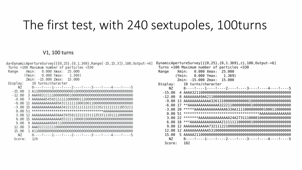
The first test, with 240 sextupoles, 100turns
V1, 100 turns
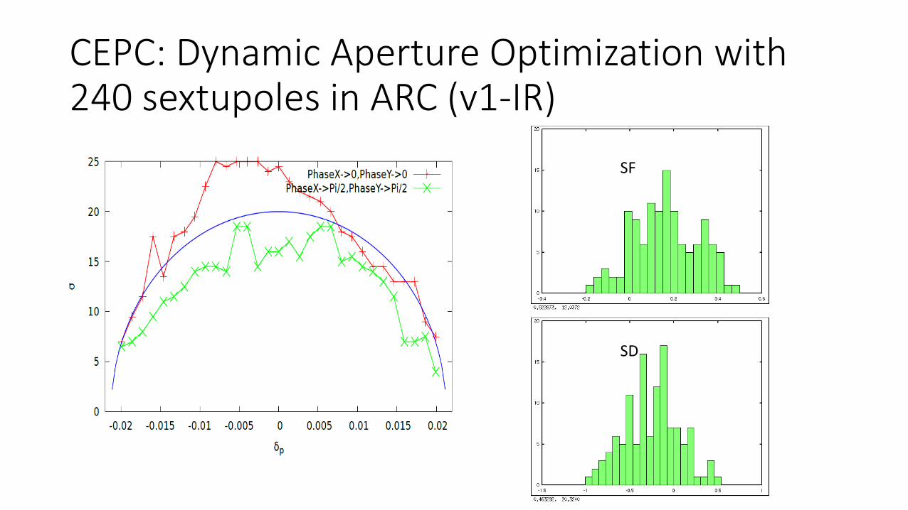
CEPC: Dynamic Aperture Optimization with 240 sextupoles in ARC (v1-IR)
SF
SD
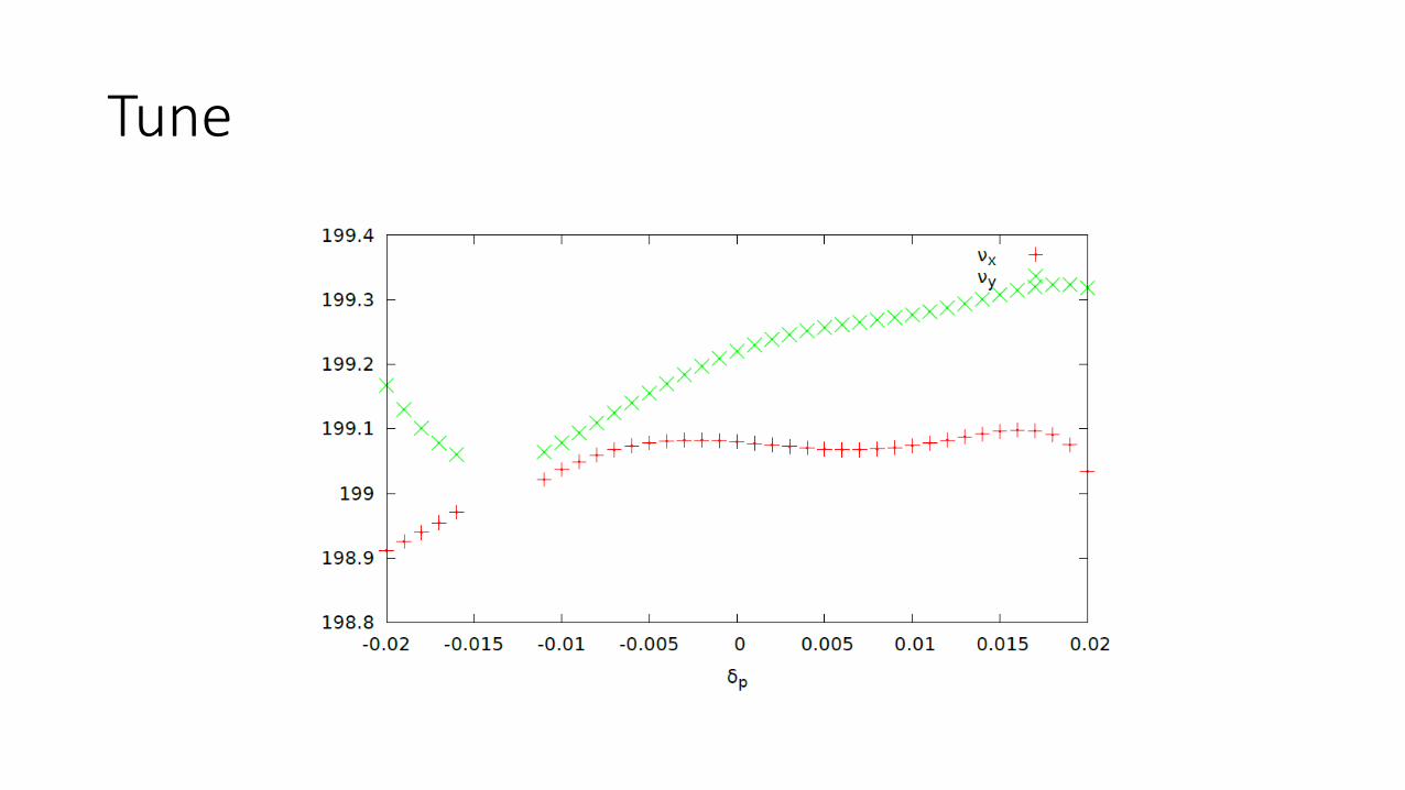
Tune
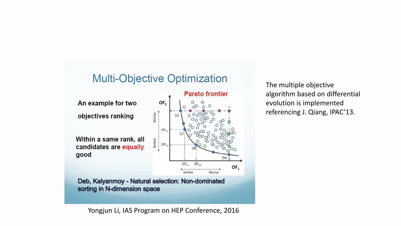
Yongjun Li, IAS Program on HEP Conference, 2016
The multiple objective algorithm based on differential evolution is implemented referencing J. Qiang, IPAC’13.
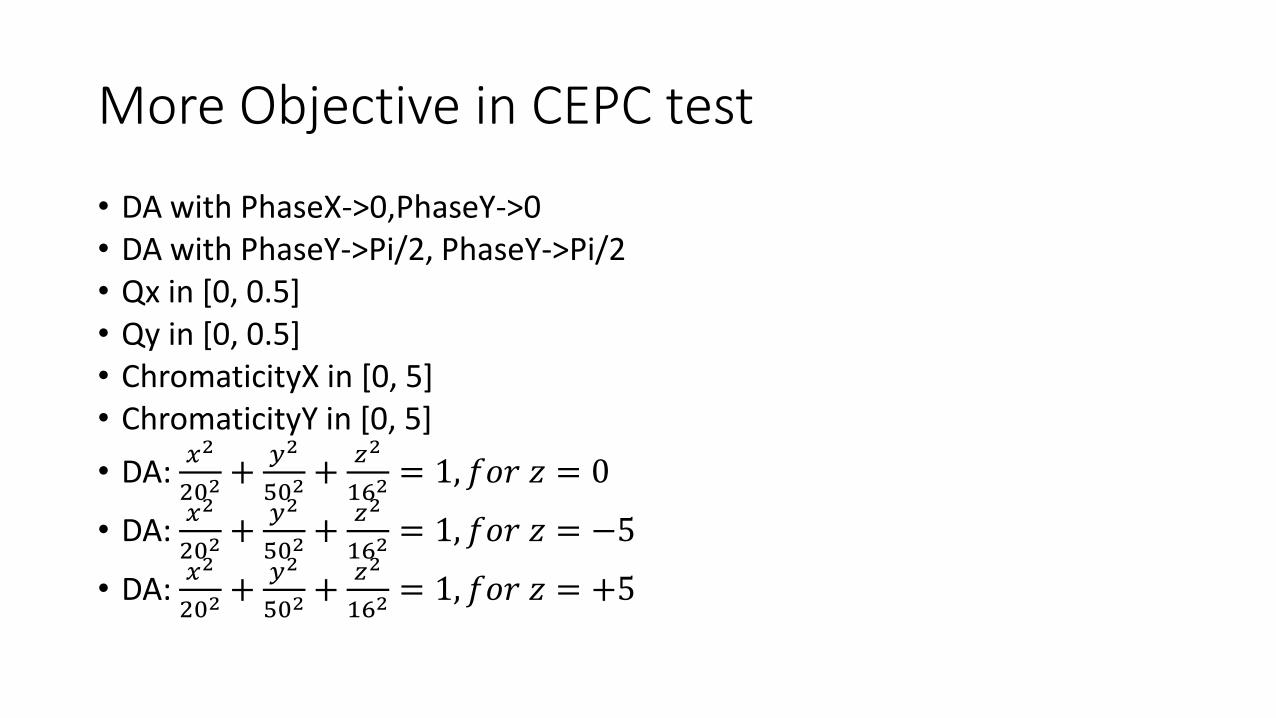
More Objective in CEPC test
• DA with PhaseX->0,PhaseY->0• DA with PhaseY->Pi/2, PhaseY->Pi/2• Qx in [0, 0.5]• Qy in [0, 0.5]• ChromaticityX in [0, 5]• ChromaticityY in [0, 5]
• DA: 𝑥2
202+
𝑦2
502+
𝑧2
162= 1, 𝑓𝑜𝑟 𝑧 = 0
• DA: 𝑥2
202+
𝑦2
502+
𝑧2
162= 1, 𝑓𝑜𝑟 𝑧 = −5
• DA: 𝑥2
202+
𝑦2
502+
𝑧2
162= 1, 𝑓𝑜𝑟 𝑧 = +5
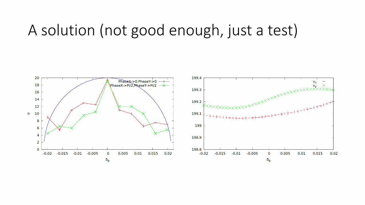
A solution (not good enough, just a test)

We have to suppress the skew sextupoleresonance, and enlarge the DA in the mean time
This is a multiple objective task.

Objective
• DA: 𝑥2
502+
𝑧2
262= 1 with PhaseX->0,PhaseY->0, for z=-26:2:26
• DA: 𝑥2
502+
𝑧2
262= 1 with PhaseX->pi/2,PhaseY->pi/2, for z=-26:2:26
•𝑦
𝜎𝑦for a particle with initial coordinate (5𝜎𝑥,0,0,0,0,0)
•𝑦− 𝑦
𝜎𝑦for a particle with initial coordinate (5𝜎𝑥,0,0,0,0,0)
• Coupling Chromaticity: 𝑅1𝑅4 − 𝑅2𝑅3 , for 𝛿 = (−0.018,+0.018)
To correct the skew sextupole nonlinear terms, the skew sextupolestrength symmetry in one pair is broken. Totally we use 24 skew sextupole.

Status of Optimization (1)

Status of Optimization (2)
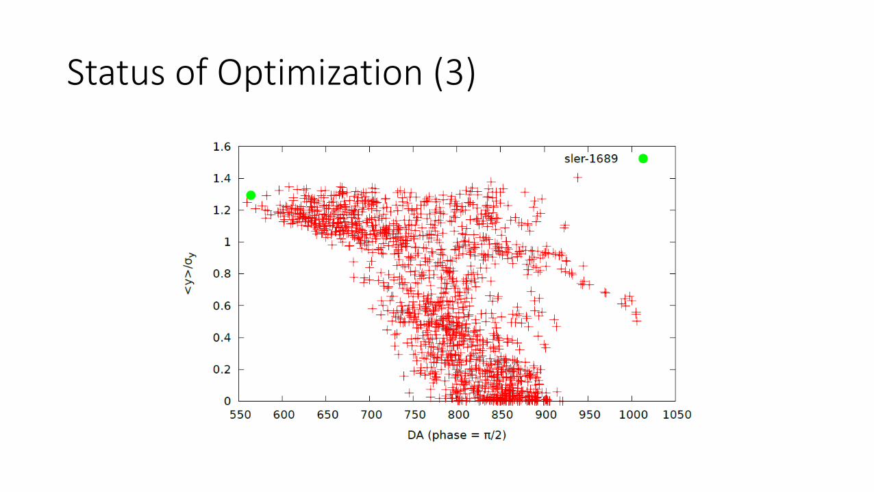
Status of Optimization (3)
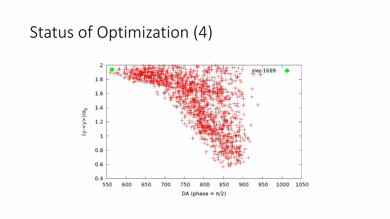
Status of Optimization (4)

It’s evolving

Other way to be tried
• Insert a skew sextupole pair before/after IP, the pair could cancel each other and help compensate the nonlinear resonance at IP. It is like the crab-waist scheme. This may need to change the linear optics.
• If the DA with suppressed skew sextupole resonance is not good enough, we may need to optimize the sextupole strength further.

Summary
• DA optimization is a complicated problem
• DA is not the only objective. Chromaticity, coupling and even nonlinearity should also be well controlled. We have a multiple objective task.
• The multi-objective optimization has been used in light source machine (not only storage ring based) for a few years
• SuperKEKB team has developed powerful optimization tool.
• We wish the Multi-Objective-Differential-Evolution could also help the optimization of SuperKEKB
• The MODE is just a tool, no physics. Physics exist in the definition of objective function.
• The tool could only help us find the ‘ceiling’ of a design. But the ‘ceiling’ is determined by the design itself.


