cerabar S Foundation Fieldbus Pressure Measurement Operating Instructions F TM TM 1 2 3 49 A B C 4...20 mA Test 1 2 3 1 2 3 49 A B C 4...20 mA Test 1 2 3 BA 211P/00/en/05.00 Software version 0.3 52006135 Hauser + Endress The Power of Know How
Transcript
cerabar SFoundation FieldbusPressure Measurement
Operating Instructions
F
TM
TM
0123456
78
9ABCD
EF
4...20 mA
Test
12
3
0123456
78
9ABCD
EF
4...20 mA
Test
12
3
BA 211P/00/en/05.00Software version 0.352006135
Hauser+EndressThe Power of Know How
Short Operating Instructions
– –
+ +
Z S
Remote operationover configurationtool
Local operationCerabar Swithout/with display– pressure onlySection 4.1
Approved usageThe pressure transmitter Cerabar S is a Foundation Fieldbus device which, dependingupon the version, is used for measuring gauge or absolute pressure. Level measurementis also possible when a Foundation Fieldbus tool is used.
Installation,commissioning,operation
The Cerabar S has been designed to operate safely in accordance with current technical,safety and EU standards. If installed incorrectly or used for applications for which it isnot intended, however, it is possible that application-related dangers may arise, e.g.product overflow due to incorrect installation or calibration. For this reason, the instrumentmust be installed, connected, operated and maintained to the instructions in this manualpersonnel must be authorised and suitably qualiflied. The manual must have been readand understood, and the instructions followed. Modifications and repairs to the deviceare permissible only when they are expressly approved in the manual.
Explosion hazardousarea
If the device is to be installed in an explosion hazardous area, then the specifications inthe certificate as well as all national and local regulations must be observed. Theinstrument can be delivered with the certificates listed in the table below. The certificatecan be identified from the first letter of the order code stamped on the nameplate.
• Ensure that all personnel are suitably qualified.• Observe the specifications in the certificate as well as national and local regulations.• Take special care with regard to the grounding of the bus cable screening.
Recommendations are to be found in the FF specification or IEC 79–14.
Code Certificate Protection
R Standard none
G CENELEC EEx ia IIC T4/T6
G ATEX 100 ATEX II 1/2 G EEx ia IIC T4/T6
I ATEX 100 PMP: ATEX II 2 G EEx d IIC T5/T6PMC: ATEX II 2 G EEx d [ia] IIC T6
D PTB, Zone 0 EEx ia IIC T4/T6
Q FM Explosion proof Class I, II, III Div. 1, Groups A…G
O FM IS Class I, II, III, Div. 1, Groups A…G
S CSA IS Class I, II, III, Div.1, Groups A…G
U CSA Explosion proof Class I, II, III, Div. 1, Groups B…G (in preparation)
Certificates for applications inexplosion hazardous areas
ENDRESS+HAUSERCERABAR S PMC/PMP
Order No. PMC xxx –Order No. PMP xxx –
Cerabar S FF Notes on Safety
Endress+Hauser 5
Safety Conventions and Symbols
In order to highlight safety-relevant or alternative operating procedures in the manual,the following conventions have been used, each indicated by a corresponding icon inthe margin.
Notes on safety
Ignition protection
Electrical symbols
Symbol Meaning
Note!A note highlights actions or procedures which, if not performed correctly, may indirectly affectoperation or may lead to an instrument response which is not planned.
Caution!Caution highlights actions or procedures which, if not performed correctly, may lead topersonal injury or incorrect functioning of the instrument.
Warning!A warning highlights actions or procedures which, if not performed correctly, will lead topersonal injury, a safety hazard or destruction of the instrument.
Device certified for use in explosion hazardous areaIf the device has this symbol embossed on its name plate it can be installed in an explosionhazardous area.
Explosion hazardous areaSymbol used in drawings to indicate explosion hazardous areas.– Devices located in and wiring entering areas with the designation “explosion hazardous
areas” must conform with the stated type of protection.
Safe area (non-explosion hazardous area)Symbol used in drawings to indicate, if necessary, non-explosion hazardous areas.– Devices located in safe areas still require a certificate if their outputs run into explosion
hazardous areas.
Direct voltageA terminal to which or from which a direct current or voltage may be applied or supplied.
Alternating voltageA terminal to which or from which an alternating (sine-wave) current or voltage may beapplied or supplied.
Grounded terminalA grounded terminal, which as far as the operator is concerned, is already grounded bymeans of an earth grounding system.
Protective grounding (earth) terminalA terminal which must be connected to earth ground prior to making any other connection tothe equipment.
Equipotential connection (earth bonding)A connection made to the plant grounding system which may be of type e.g. neutral star orequipotential line according to national or company practice.
Note!
Caution!
Safety Conventions and Symbols Cerabar S FF
6 Endress+Hauser
1 Introduction
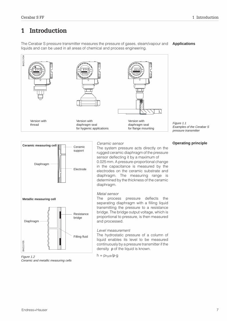
ApplicationsThe Cerabar S pressure transmitter measures the pressure of gases, steam/vapour andliquids and can be used in all areas of chemical and process engineering.
Operating principleCeramic sensorThe system pressure acts directly on therugged ceramic diaphragm of the pressuresensor deflecting it by a maximum of0.025 mm. A pressure-proportional changein the capacitance is measured by theelectrodes on the ceramic substrate anddiaphragm. The measuring range isdetermined by the thickness of the ceramicdiaphragm.
Metal sensorThe process pressure deflects theseparating diaphragm with a filling liquidtransmitting the pressure to a resistancebridge. The bridge output voltage, which isproportional to pressure, is then measuredand processed.
Level measurementThe hydrostatic pressure of a column ofliquid enables its level to be measuredcontinuously by a pressure transmitter if thedensity ρ of the liquid is known.
h = phydr/ρ·g
0 - 10 bar0 - 10 bar 0 - 10 bar
Version withthread
Version withdiaphragm sealfor flange mounting
Version withdiaphragm sealfor hygienic applications
BA
211Y
04
Figure 1.1Examples of the Cerabar Spressure transmitter
BA
211Y
05
Ceramicsupport
Electrode
Resistancebridge
Filling fluid
Diaphragm
Diaphragm
Ceramic measuring cell
Metallic measuring cell
Figure 1.2Ceramic and metallic measuring cells
Cerabar S FF 1 Introduction
Endress+Hauser 7
1.1 Measuring system
Measuring point In the simplest case, the complete measuring point comprises:• Cerabar S transmitter with Foundation Fieldbus protocol• Network Configuration Tool, e.g. National Instruments Fieldmanager
Number of transmitters The maximum number of transmitters on a bus segment is determined by their currentconsumption, the required bus length and if installed the power of the link.Normally, however:
• 10 Cerabar S for EEx ia applications• max. 32 Cerabar S for non-hazardous application
can be operated on a bus segment. Cerabar S consumes max. 11.5 mA per device.
Refer also to the FF specification or IEC 61158-2 or to the Internet address"http://www.fieldbus.org".
TT
0 - 10 bar0 - 10 bar
0 - 10 bar0 - 10 bar
0 - 10 bar0 - 10 bar
Personalcomputer e.g.with NI-FBUSconfigurator
BA
211Y
06
Cerabar S withFF protocol
power supply
power conditioner
Figure 1.3Measuring point with Cerabar S
T: bus terminator
1 Introduction Cerabar S FF
8 Endress+Hauser
2 Installation
This section describes the mechanical installation of Cerabar S with and withoutdiaphragm seals.
2.1 Mounting instructions without diaphragm seal
Cerabar Swithout diaphragm seal– PMC 731– PMP 731
The Cerabar S without diaphragm seal is mounted in the same way as a manometer. Theuse of shut-off valves and pigtails is recommended. Its position depends upon theapplication.
• Measurement in gases:Mount the shut-off valve above thetapping point so that condensate canrun back into the process.
• Measurement in steam:Mount with a pigtail above the tappingpoint.The pigtail reduces the temperature infront of the diaphragm to almostambient temperature. The pigtail mustbe filled with water before start-up.
0 - 10 bar
BA
211Y
07
Figure 2.1Mounted on a shut-off valve formeasuring gases
0 - 10 bar
BA
211Y
08
Figure 2.2Mounted with U-shaped pigtailfor measuring steam/vapour
0 - 10 bar
BA
211Y
09
Figure 2.3Mounted with circular pigtail formeasuring steam/vapour
Cerabar S FF 2 Installation
Endress+Hauser 9
• Measurement in liquids:Mount on the shut-off valve below thetapping point or at the same height
PVDF adapter For instruments with PVC adapter, a maximum torque of 7 Nm is permitted. The threadconnection may become loose at high temperatures and pressures. This means that theintegrity of the thread must be checked regularly and may need to be tightened usingthe torque given above. Teflon tape is recommended for sealing with the ½ NPT thread.
Mounting the PMP 731 The PMP 731 with metallic sensor is available in the following versions:• with flush-mounted diaphragm or• with adapter and internal diaphragm.
The adapter can be screwed on or welded in.A seal is enclosed appropriate to the material used and version.
0 - 10 bar
BA
211Y
10
Figure 2.4Mounted on a shut-off valve for measuring liquids
Figure 2.5left:An elastomer sealto DIN 3852-E-G ½ is suppliedwith the thread adapterright:With internal diaphragm andwelded or thread adapter
Process connection withflush-mounted diaphragmversion 1F
With internal diaphragm andthread adapter
Seal supplied(with 1.4435 diaphragm only)
Welded
Welded adapter– Material 1.4571
with 1.4435 diaphragm– Material Hastelloy
with diaphragm inHastelloy
BA
211Y
12
2 Installation Cerabar S FF
10 Endress+Hauser
2.2 Mounting instructions with diaphragm seal
Cerabar Swith diaphragm seal– PMC 635– PMP 635
The Cerabar S with diaphragm seal isscrewed in, flanged or clamped,depending on the type of diaphragm seal.• The protective cap of the diaphragm
seal should only be removed just beforemounting in order to protect thediaphragm.
• The diaphragm of the diaphragm seal ofthe Cerabar S must not be pressed in orcleaned with pointed or hard objects.
• The diaphragm seal and the pressuresensor together form a closed andcalibrated system which is filled withfilling fluid through a hole in the upperpart. The following rules should beobserved:– This hole is sealed and not to be
opened.– The instrument should only be turned
by the diaphragm seal and not by thehousing.
Level measurementFor level measurement the Cerabar S mustalways be installed below the lowestmeasuring point.• The instrument should not be installed
within the flow of material, in the outletof the tank or at a place in the tankwhere pressure pulses from agitatorblades may occur.
• Calibration and function testing areeasier to carry out if the Cerabar S ismounted downstream from a shut-offvalve.
Mounting withtemperature spacers
The use of temperature spacers isrecommended when the continuousextreme product temperatures cause themaximum permissible ambienttemperature to exceed +85 °C.• Note when mounting that the
temperature spacer increases themaximum height by 100 mm.
• Due to the hydrostatic column in thetemperature spacer, the increasedheight also causes a zero point shift ofapprox. 10 mbar.
0 - 10 bar
BA
211Y
13
Figure 2.6When screwing in the Cerabar Swith diaphragm seals, turn by thediaphragm seal only, not by thehousing.
0-
10bar
BA
211Y
14
0 - 10 bar
A +
100
100
BA
211Y
15
Figure 2.7Temperature spacer
Cerabar S FF 2 Installation
Endress+Hauser 11
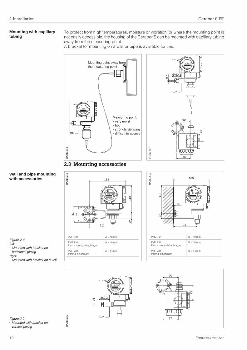
Mounting with capillarytubing
To protect from high temperatures, moisture or vibration, or where the mounting point isnot easily accessible, the housing of the Cerabar S can be mounted with capillary tubingaway from the measuring point.A bracket for mounting on a wall or pipe is available for this.
2.3 Mounting accessories
Wall and pipe mountingwith accessories
0 - 10 bar
Mounting point away fromthe measuring point
Measuring point:• very moist• hot• strongly vibrating• difficult to access
BA
211Y
160 - 10 bar
Ø 60.3
90
87
73
Ø 6
BA
211Y
17
183
81
A*
118
70
111
/ 60,3
0 - 10 bar
PMC 731 A = 19 mm
PMP 731Flush-mounted diaphragm
A = 18 mm
PMP 731Internal diaphragm
A = 44 mm
BA
211Y
18
Figure 2.8left:• Mounted with bracket on
horizontal pipingright:• Mounted with bracket on a wall
118
B*
3
94
166
0 - 10 bar
BA
211Y
19
ø60,3
90
ø6
73
87
0 - 10 bar
BA
211Y
20
Figure 2.9• Mounted with bracket on
vertical piping
PMC 731 B = 19 mm
PMP 731Flush-mounted diaphragm
B = 18 mm
PMP 731Internal diaphragm
B = 44 mm
2 Installation Cerabar S FF
12 Endress+Hauser
2.4 Mounting position
Positioning the housingAfter the Cerabar S has been mounted, the housing can be positioned so that:
• the terminal connection compartment can be accessed easily,• the display can be seen optimally,• the cable entry and cover of the Z/S keys are protected from water.
The housing can turned through 270°:• To turn the housing undo the screw below the connection compartment• Turn the housing• Tighten the screw again
0 - 10 bar
BA211Y21
loosen
tighten
Z S
BA211Y22
Vertical mounting
Cable pointsdownwards
Figure 2.10Mounting of the Cerabar S• cable points downwards• The cover for the Z/S keys is on the side of the
instrument
Cerabar S FF 2 Installation
Endress+Hauser 13
2.5 Connection
General notes Cerabar S is loop-powered transmitter (type 111) with Foundation Fieldbus output. Notethe following before connecting up:
• Turn off the power before connecting up.• Connect the external ground terminal of the transmitter to the plant grounding
system before connecting up.
Power The Cerabar S has the following power requirements:I = 10.5 mA ± 1 mANon-Ex: U = 9...32 VDCEx: U = 9…24 VDC
Cable Twisted, shielded pairs must be used. The cable specifications can be taken from theFF specification or IEC 61158-2. The following have been found suitable:
Screening General information on wiring can be found at the Fieldbus Foundation website:www.fieldbus.org. For maximum protection against electromagnetic interference, e.g.when the bus is operating near frequency converters, it is recommened that high integritypotential bonding be provided between the housing and the cable screening.
The external ground terminal on the transmitter must be connected to ground.The continuity of the cable screening between tapping points must be ensured.The screening must be grounded at each end of the cable.If there are large differences in potential between grounding points, the grounding shouldrun via a capicitor that is suitable for high frequency use(e.g. ceramic 10 nF/250 V~).
ENDRESS+HAUSER Made in GermanyMaulburg
CERABAROrder Code PMC731-R11P1F11R1
Ser.-No. 4FY0832
Material AL203 CRN-STEEL VITON IP 65
P –1...10 bar
Pmin. 500 mbar
Pmax. 40 bar U = 9…32VDC
Foundation Fieldbus
1 2 3+
0004Foundation Fieldbus
FF FF
cable gland
Nameplate
externalground
connectioncompartment
BA211Y23
groundterminal
Figure 2.11Cerabar S connectioncompartment and nameplate
2 Installation Cerabar S FF
14 Endress+Hauser
2.6 Wiring examples
Cable connectionThe bus line also carries power and isconnected as follows:
• Switch off power• If necessary, connect external ground
terminal to plant grounding system.• Unscrew the connection compartment
lid.• Thread cable through cable entry.• Connect cable cores to FF+ and FF–.
Reversed polarity has no effect onoperation.
• Connect the screen to the internalground terminal
• Screw down the connectioncompartment lid.
FF connectorDevices fitted with the Foundation Fieldbusconnector are already wired. Theconnector is simply plugged into the socketon the T-box or ready-made extensioncable:
• Push connector into socket.• Tighten knurled screw.• Ground T-box and device according to
selected grounding concept.
Note!To avoid the effects of vibration, alwaysconnect the Cerabar S using a cable.
BA
211Y
25
7/8" FF connectorfitted ex-works
Cerabar S
to e.g. Turckjunction box
FF–
FF+
1 2 3+
0004Foundation Fieldbus
FF FF
ground terminalon housing:to be grounded!
connectioncompartent
BA
211Y
24
Note!
Cerabar S FF 2 Installation
Endress+Hauser 15
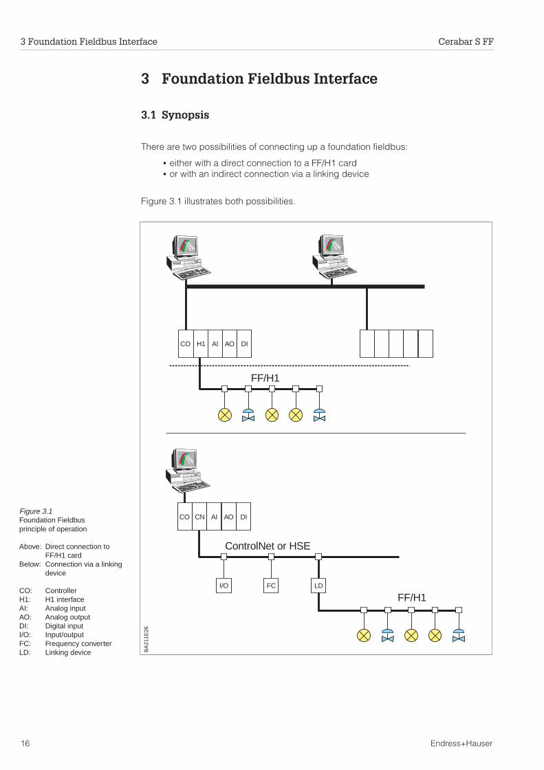
3 Foundation Fieldbus Interface
3.1 Synopsis
There are two possibilities of connecting up a foundation fieldbus:
• either with a direct connection to a FF/H1 card• or with an indirect connection via a linking device
Figure 3.1 illustrates both possibilities.
CO
CO
I/O FC LD
H1
CN
AI
AI
AO
AO
DI
DI
FF/H1
FF/H1
ControlNet or HSE
BA
211E
26
Figure 3.1Foundation Fieldbusprinciple of operation
Above: Direct connection toFF/H1 card
Below: Connection via a linkingdevice
CO: ControllerH1: H1 interfaceAI: Analog inputAO: Analog outputDI: Digital inputI/O: Input/outputFC: Frequency converterLD: Linking device
3 Foundation Fieldbus Interface Cerabar S FF
16 Endress+Hauser
3.2 Hardware settings
A DIP-switch in the connection compartment of the Cerabar S controls allows thewrite protection and simulation functions to be set via hardware.
The default settings of the switches are as follows:
WP OFF: write protection via hardware is disabledSIM ON: simulation is enabled (= allowed in configuration tool).
Device identificationFoundation Fieldbus identifies the device by its identification code and automaticallyallocates an appropriate field address. There is no separate hardware switch for thispurpose.
When the device has been integrated into the network, see Chapter 3.3, it appears asfollows in the bus tree:
E+H_CERABAR_S_XXXXXXXX
A click on the name reveals the device tag, device ID and node address. The deviceID is made up of the following components:
Device_ID = 452B481007-XXXXXXXX
whereby: 452B48 = ID code for Endress+Hauser1007 = ID code for Cerabar SXXXXXXXX = Device serial number, as printed on the name plate
A right-hand mouse click on the name opens up a menu from which the PD_TAG andNODE_ADDRESS can be changed.
WP
off on off on
SM
WP
off on off on
SM
WP
off on off on
SM
BA
211Y
27
Default settings:Simulation on
Write protection on:
Figure 3.2Cerabar S DIP-switch
Cerabar S FF 3 Foundation Fieldbus Interface
Endress+Hauser 17
3.3 Network configuration
During the configuration of the FF network, the device description (DD) of theCerabar S must be downloaded into the directory foreseen for it.
• Start the interface configuration tool.• Configure the interface.• Call the DD download routine• Download the device descriptions (.ffo and .sym files) to the directory offered.• When the configuration is complete, close the tool and the FF stack (if open).
The Cerabar S device descriptions can be ordered direct from Endress+Hauser ordownloaded from our website www.endress.com. They contain all data necessary tooperate Endress+Hauser Foundation Fieldbus devices.
Start-up Start the bus configuration tool. After start-up, the tool shows the network configurationin the form of an expandable tree. If the Cerabar S has been connected correctly, itcan now be identified:
——E+H_CERABAR_S_XXXXXXXX—
A double click on the name reveals the device data, see also page 17:
PD_TAG the physical name of the deviceDEVICE_ID the unique device identifierNODE_ADDRESS the fieldbus node to which the device is connected
(is automatically allocated by the Configurator)
A click on the name expands the device tree to show the function blocks available forit:
The relationship between the blocks is shown in Fig. 3.3, the function of each block inChapters 3.4 to 3.6.
Transducer Block
Resource BlockSensor
Analog Input Function Block
PRIMARYVALUE OUT
OU
T_S
CA
LE
XD_SCALE 0 10
1
ORSECONDARYVALUE
Measuredvariable
e.g. PCSor other
Parameters thatdescribe thephysical unit, e.g.Tag No.
Signal evaluation
Parameters thatdescribe thedevice settings
Parameter that are important to theprocess control system, e.g. scaling,
BA
211Y
28
Figure 3.3Block model of device
3 Foundation Fieldbus Interface Cerabar S FF
18 Endress+Hauser
3.4 Resource block
The resource block contains the parameters used to describe physical resources ofthe device. It has no linkable inputs or outputs. It is opened by a click on theresource line.——E+H_CERABAR_S_XXXXXXXX
If the NI-FBUS Configurator is being used, a series of file tabs appears on the screen.The files can be opened to view and/or edit the parameters in the following table. Ashort description of the parameter function appears on the side of the screen. Achange in the parameter is stored by pressing the WRITE CHANGES button when theblock is out of service. Press the READ ALL button to check the values stored in thedevice. The following are of particular interest.
The function of the resource block parameters not described here can can be takenfrom the Foundation Fieldbus specification, see "http://www.fieldbus.org".
Parameter Description
TAG_DESC User description of the intended application of the block.
MODE_BLK Lists the actual, target, permitted and normal operating modes of theblock.
Target: changes the operating mode of the blockActual: indicates the current operating mode of the blockPermitted: states which operating modes are allowedNormal: indicates the normal operating mode of the block
The possible operating modes of the resources block are:AUTO: the block is operating as normalOOS: the block is out of service.
If the resource block is out of service, then all blocks within the device(resource) are forced into the same status.
RS_STATE Indicates the state of the resource block application state machineOn-line: block in AUTO modeStandby: block in OOS mode
WRITE_LOCK Indicates the status of DIP-switch WP.
RESTART Allows a manual restart:UNINITIALISED: no statusRUN: normal operational statusRESOURCE: resets the resource block parametersDEFAULTS: Resets all Foundation Fieldbus parameters within the device,but not the manufacturer specific parameters.PROCESSOR: make a warm start of the processor
BLOCK_ERROR Shows error status of software and hardware componentsOut-of-Service: the block is in OOS modeSimulation active: shows the setting of DIP-switch WP
BLOCK_ALM Shows any configuration, hardware, connection and system problems inthe block. The cause of the alert is to be seen in the subcode field.
Cerabar S FF 3 Foundation Fieldbus Interface
Endress+Hauser 19
3.5 Transducer block
The transducer block contains the parameters required to calibrate the device.
Operation The transducer block is opened by clicking on the transducer line.
Parameters changes from the tool are made off-line while the device is operating. Thechanges are downloaded by first setting MODE_BLK = OOS then pressing the WRITECHANGES button. Press the READ ALL button to check the values stored in thedevice. Normally operation is resumed as soon as MODE-BLK is set to AUTO.
DA
MP
ING
Sensorpressure
PD
DP'
PD
DP'Unbiasedpressureτ
LOW
SE
NS
OR
CA
L
HIG
HS
EN
SO
RC
AL
Flow
Levellinear
Levelcylinder
PrimaryValue (PV)
p
1
0
1
p0
1
p0
Q
10
LOW
ER
RA
NG
EV
ALU
EU
PP
ER
RA
NG
EV
ALU
E
DE
NS
ITY
FAC
TOR
STA
RT
PO
INT
FU
LLS
CA
LE
UN
ITA
FT
ER
LIN
EA
RIZ
ATIO
N
LIN
EA
RIZ
ATIO
N
Sensortemperature
SecondaryValue (SV)
Pressure
1
1
0
1
1
0
1
1
0
10
l
10
10
V
Output scalingInput scaling
CR
EE
PF
LOW
SU
PP
RE
SS
ION B
A21
1Y29
Figure 3.4Schematic diagram of transducer block: the parameters shown represent a typical calibration sequence for a standard application
3 Foundation Fieldbus Interface Cerabar S FF
20 Endress+Hauser
Block administration
Output values
Output values
Configurationparameters
The parameters listed in the following table are manufacturer-specific and can beused to configure the device as described in Chapter 5 and 6. Refer also to Fig.: 3.4.
The transducer block also contains standard profile parameters. Some of these, e.g.CAL_POINT_HI and CAL_POINT_LO can be changed but have no effect on thedevice. If the user desires, however, he can enter data relevant to the calibration inthe SENSOR_CAL_ parameters and enter a tag description for the transducer block inTAG_DESC.
Parameter Description
MODE_BLK See description in Resource block.The possible operating modes of the transducer block are:
AUTO: the block is operating as normal.MAN: the block is operated with a manually entered primary value.OOS: the block is out of service.
TAG_DESC User description of the intended application of the block.
BLOCK_ERROR Shows the error status associated with the block componentsOut-of-Service: the block is in OOS mode.Simulation active: shows the setting of DIP-switch WP.Input failure/process variable has BAD status.
Parameter Description
PRIMARY_VALUE Primary value output by transducer block, here it is pressure orlinearization value
SECONDARY_VALUE Secondary value output by transducer block, here it is temperature
Parameter Description
Measured Value * Indicates the current value measured by the device.
Lower RangeValue Entry of pressure for lower range-value – zero, (affects bargraph)
Upper RangeValue
Entry of pressure for upper range-value – span, max. turndown 20:1(affects bargraph)
Set Lower RangeValue Acting pressure is taken as lower range-value – zero, (affects bargraph)
Set UpperRange Value
Acting pressure is taken as lower range-value – span,max. turndown 20:1, (affects bargraph)
Set BiasPressure
Entry of bias pressure, parameter "Biased Pressure" adopts the new value.Operating mode "linear" (pressure): Display correction for parameters"Measured Value", "Upper Range Value" and "Lower Range Value"
Bias PressureAutomatically
Acting pressure is taken as bias pressure, parameter "Biased Pressure"adopts the new value.Operating mode "linear" (pressure): Display correction for parameters"Measured Value", "Upper Range Value" and "Lower Range Value"
Set OutputDamping
Sets the damping time for the transducer block output signal (PrimaryValue), Range: 0 - 40 s
* Display value
Cerabar S FF 3 Foundation Fieldbus Interface
Endress+Hauser 21
Configurationparameters (cont.)
Parameter Description
Select PressureUnit
Changes the pressure units. Options: mbar, bar, Pa, hPa, kPa, MPa, mmH2O, m H2O, in H2O, ft H2O, psi, g/cm2, kg/cm2, kgf/cm2, atm, Ib/ft2, Torr,mm Hg or in Hg (All pressure-specific parameters are recalculated andshown in these units.)
Diagnostic Code * Indicates the current diagnostic code with associated message of anydevice alarm, see Chapter 7.1.
LastDiagnostic *
Indicates the previous diagnostic code with message registered by thedevice, see Chapter 7.1.
Clear LastDiagnostic Code
Clears last diagnostic code. Options: # – no action, clear – message isdelected
Transducer_sw_vers * Indicates the measuring software version of the device.
Min. Pressure * Maximum pointer function for the smallest measured pressure value
Reset Min. PresPeak Hold
Options: # – no action, reset – Acting pressure value is adopted for theparameter "Min. Pressure".
Max. Pressure * Maximum pointer function for the largest measured pressure value
Reset Max. PresPeak Hold
Options: # – no action, reset – Acting pressure value is adopted for theparameter "Max. Pressure".
IntegerCounter high *
Counter for pressure values above the upper range-limit (parameter "HighSensor Calibration"), max value = 255Options: # – no action, clear – counter is reset to "0"
SensorTemperature * Display of actual measured temperature in the selected unit
Min. Temperature* Maximum pointer function for the smallest measured temperature
Reset minTemp. Peak Hold
Options: # – no action, reset – Current temperature is adopted for theparameter "Min. Temperature".
Max.Temperature* Maximum pointer function for the largest measured temperature
Reset maxTemp. Peak Hold
Options: # – no action, reset – Current temperature is adopted for theparameter "Max. Temperature".
Default Values When "5140" is entered here the device parameters are reset to theirfactory setting, see Chapter 7.2.
Linearization
(operating mode)
Adjusting the operating mode. Options: linear (pressure), square rootfunction (flow), level linear (level, volume or weight), level horizontalcylinder (volume and weight)
Start Point For operating modes: "square root function", "level linear" and "levelhorizontal cylinder" – zero for output scaling (corresponds to lowerrange-value)
Full Scale For operating modes: "square root function", "level linear" and "levelhorizontal cylinder" – scale value for output scaling (corresponds to upperrange-value)
Unit AfterLiniarization
Selecting units for measuring the level, volume, weight or flow – theoptions depend on the operating mode selected. The linearized value isshown in "Measured Value" in these units. The measured value is notconverted into the new units.
* Display value
3 Foundation Fieldbus Interface Cerabar S FF
22 Endress+Hauser
Configurationparameters (cont.)
Parameter Description
Density Factor For operating modes: "level linear" and "level cylinder" - applications withmedia with a density not equal to 1 gm/cm³. The pressure is divided bythis factor before carrying out the linearization function. This ensures thatit is adapted to the material.
Creep FlowSuppression
Only for operating mode: "square root function" (flow).Entry is always in % of flow.Suppresses the display on small flow rates.
Low SensorCalibration Sets the low sensor calibration value.
High SensorCalibration Sets the high sensor calibration value.
Low SensorLimit * Lower range-limit of sensor (Unit selectable with "Select Pressure Unit")
High SensorLimit * Upper range-limit of sensor (Unit selectable with "Select Pressure Unit")
Sensor Pressure* Sensor pressure (Unit selectable with "Select Pressure Unit")
Temperature Unit Changes the temperature units. Options: °C, K,°F
UnbiasedPressure * Display of current pressure value without bias correction
Biased Pressure*
Display of current pressure value with bias correction, (corresponds to theparameter "Measured Value", when the operating mode is set to "linear"(pressure)).
Security Locking Software write lock for the parameters: a number ≠ 130 locks theparameter, 130 unlocks the parameter, see Chapters 5.5 and 6.6.
Serial-No.SENS. * Display of the sensor serial number
ProcessConn. P+ Material of process connection + side
ProcessConn. P– Material of process connection – side
Gasket Material of seal
ProcessDiaphram. Material of diaphragm
Fill Liquid Oil filling
* Display value
Cerabar S FF 3 Foundation Fieldbus Interface
Endress+Hauser 23
3.6 Analog input block
The analog input block conditions the signal output by the transducer block andoutputs signal to the PCS or other function blocks.
Operation The block is opened by a click on the analog input line.
Parameters changes from the tool are made off-line while the device is operating. Thechanges are downloaded by first setting MODE_BLK = OOS then pressing the WRITECHANGES button. Press the READ ALL button to check the values stored in the de-vice. Normally operation is resumed as soon as MODE-BLK is set to AUTO.
Block administration
PRIMARYVALUE (PV)
L_T
YP
E
XD
_SC
ALE
SIM
ULA
TE
CH
AN
NE
L
DIRECT
INDIRECT
INDIRECTSQRT
OU
T_S
CA
LE
ALA
RM
S
OUT
HI_HI
HI
LO
LO_LO
EU
0 1
0
1
0
1
0 1
FIELD_VAL PV
EU
EU
EU
τ
PV
_TIM
E
MO
DE
STA
TU
S
SECONDARYVALUE (SV)
CHANNELVALUE
e.g. PCSor other
Output scalingInput scaling
BA
211Y
30
Alarmconfiguration
Statuscalculation
Valueoutput bytransducerblock
Figure 3.5Schematic diagram of analog input block as used in AUTO mode
Parameter Description
TAG_DESC User description of the intended application of the block.
MODE_BLK See description in Resource blockThe possible operating modes of the analogue input block are:
AUTO: the block is operating as normal.MAN: the block is operated with a manually entered primary value.OOS: the block is out of service.
BLOCK_ERROR Shows the error status associated with the block components.Out-of-Service: the block is in OOS mod.eSimulation active: shows the setting of DIP-switch WP.Input failure/process variable has BAD status
3 Foundation Fieldbus Interface Cerabar S FF
24 Endress+Hauser
Output values
Scaling
The relationship between the output values and scaling paramaters for the Cerabar Sis as follows:
FIELD_VAL = 100 x (CHANNEL VALUE - XD_SCALE_MIN)(XD_SCALE_MAX - XD_SCALE_MIN)
The L_TYPE parameter influences the signal conversion.
Direct:
PV = CHANNEL_VALUE
Indirect:
PV = FIELD_VAL x (OUT_SCALE_MAX - OUT_SCALE_MIN) + OUT_SCALE_MIN100
Indirect square root:
PV = FIELD_VAL x (OUT_SCALE_MAX - OUT_SCALE_MIN) + OUT_SCALE_MIN100
The XD_SCALE and OUT_SCALE values are expressed in engineering units at 0% forMIN and 100% for MAX.
Output response
Parameter Description
PV Either the primary transducer block value used to execute the block or aprocess value associated with it. Comprises value and status.
OUT The primary value output as a result of executing the analog input block.Comprises value and status.
FIELD_VALUE Raw value of field device in % of PV range with a status reflecting thetransducer condition before signal characterisation L_Type or filteringPV_TIME. Comprises value and status.
Parameter Description
CHANNEL Selects the measured value to be input to the analogue input block0 = no channel defined1 = primary value, here it is pressure or linearization value2 = secondary value, here it is: sensor temperature
XD_SCALE Scales the transducer block value in the required engineering units (EU).
OUT_SCALE Scales the output value in the required engineering units (EU).
L_TYPE Sets the linearization type:DIRECT: the transducer block value bypasses the scaling functionsINDIRECT:the transducer block value is fed through the linear scalingfunctionsINDIRECT SQRT: the transducer block value is fed through the squareroot scaling functions
Parameter Description
LOW_CUT Not relevant to level measurement!Determines a threshold for square root linearisation below which theoutput value is set to zero.
PV_FTIME Sets the time constant for the output value.
Cerabar S FF 3 Foundation Fieldbus Interface
Endress+Hauser 25
Alarms
Alarm priorities
Alarm status
Simulation The SIMULATE parameter allows transducer block output value to be simulated,provided simulation has also been enabled at the device DIP switch. The simulationmust be enabled, a value and/or status entered and the block must be in AUTOmode. During simulation the transducer output value is substituted by the simulatedvalue.
A simulation is also possible by switching the block to manual and entering a value forOUT, see Chapter 7.2.
Parameter Description
ACK_OPTION Sets the way in which alarms and warnings are to be acknowledged.
ALARM_HYS Sets the hysteresis (in output engineering units) for all configured alarms.A hysteresis of e.g. 2% on a HI_HI_LIMIT of 95% would cause the alarmto activate when the level reaches 95% and to deactivate when the leveldrops below 93%.A hysteresis of e.g. 2% on a LO_LO_LIMIT of 5% would cause the alarmto activate when the level drops below 5% and to deactivate when thelevel rises to 7%.
HI_HI_PRI The priority (1 – 15) of the HI_HI alarm
HI_HI_LIM Sets the HI_HI alarm limit in output engineering units
HI_PRI The priority (1 – 15) of the HI alarm
HI_LIM Sets the HI warning limit in output engineering units
LO_PRI The priority (1 – 15) of the LO alarm
LO_LIM Sets the LO warning limit in output engineering units
LO_LO_PRI The priority (1 – 15) of the LO_LO alarm
LO_LO_LIM Sets the LO_LO alarm limit in output engineering units
Priority Description
0 Alarm is suppressed
1 Recognised by the system but not reported
2 Reported to the operator, but does not require his attention
3 – 7 Advisroy alarms of increasing priority
8 – 15 Critical alarms of increasing priority
Parameter Description
HI_HI_ALM The status of the HI_HI alarm
HI_ALM The status of the HI alarm
LO_ALM The status of the LO alarm
LO_LO_ALM The status of the LO_LO alarm
Parameter Description
SIMULATE Enables, sets and displays a simulated value, options:enable/disablesimulated valueoutput value
3 Foundation Fieldbus Interface Cerabar S FF
26 Endress+Hauser
3.7 Control loops
The following is an example of a simple control loop which uses the level analog inputblock, flow analog input block, two PID blocks (e.g. from flowmeter and valve) and avalve analog output block. The connections between the function blocks can bemade in the configuration tool.
LEVEL1LI01
CONVAL1
LC01
FC01
FLOW1FI01
VALVE1FX01
BA
211Y
31
Figure 3.6Schematic diagram of controlloop
LI01
FI01
FX01
OUT
OUT
AI
AI
HMI
AO
LEVEL1
FLOW1
VALVE1
LC01
AUTO
AUTO
AUTO
CAS
CASFC01
OUT
OUT
IN
IN
SP
CAS_IN
CAS_IN
BKCAL_IN
BKCAL_IN
BKCAL_OUT
BKCAL_OUT
BKCAL_OUT
PID
PID
CONVAL1
BA
211Y
32
Figure 3.7Function block connections
Cerabar S FF 3 Foundation Fieldbus Interface
Endress+Hauser 27
3.8 Methods
The Foundation Fieldbus specification provides for the use of so-called methods tosimplify the operation of the device. A method is an interactive sequence of steps thatmust be followed in order to obtain a particular function from the device.
Thus, for example, the steps given in Chapters 5.2 and 5.3 for the basic calibration ofthe device:
• Reset• Lower Range Value• Upper Range Value• Bias Pressure• Damping
might comprise a method named "Basic calibration step 1". The user could call upthis method to calibrate the device. He need do nothing else but supply theinformation which the method asks for as it progresses through each step. The settingof the block mode, reading, writing and checking of the parameters etc. areautomatically done by the program.
A method is part of the device description supplied with the device. It is intended thatmethods will be provided for all Endress+Hauser devices. The current devicedescription of the Cerabar S, however, does not support methods at this stage.
3 Foundation Fieldbus Interface Cerabar S FF
28 Endress+Hauser
3.9 Checklist for commissioning
1. Configure the network and integrate the device.− Identify the device by means of the device ID and serial number.
− If appropriate, assign a new PD_TAG, see page 17.
2. Configure the resource block, see Chapter 3.4.− Check the position of the hardware switch in WRITE_LOCK:
− If "locked" is displayed, change the position of the DIP-switch, see Chapter 3.2.
− If appropriate, change the block tag (right-hand click on tree).
− Set MODE_BLK_TARGET to Out-of-Service.
− Reset the device to factory values by using the function RESTART => Defaults
(this function may also be available with a right-hand click on the device name).
− If appropriate, assign a tag description (TAG_DESC).
− Set MODE_BLK_TARGET to Auto.
3. Configure the transducer block, see Chapters 3.5, 5 and 6.− If appropriate, change the block tag (right-hand click on tree).
− Set MODE_BLK_TARGET to Out-of-Service.
− If appropriate, assign a tag description (TAG_DESC).
− Configure the device as described in Chapters 5 or 6 (via configuration tool).
− Set MODE_BLK_TARGET to Auto.
4. Configure the analog input block, see Chapters 5.6 and 6.7.− If appropriate, change the block tag (right-hand click on tree).
− Set MODE_BLK_TARGET to Out-of-Service.
− If appropriate, assign a tag description (TAG_DESC).
− Set Channel to 1.
− Set L_TYPE to "DIRECT" if the OUT value is to be in technical units e.g. bar
to "INDIRECT" if the OUT value is to be scaled, see page 24 or Chapters 5.6 or 6.7.
− Set the desired output damping in PV_TIME.
− If appropriate, set the advisory and critical alarms.
− Set MODE_BLK_TARGET to Auto.
5. Link the function blocks in the function block editor.
6. If appropriate, check the configuration by using the SIMULATE function,see also Chapter 8.2.
7. Download the configuration (right-hand click on device name).
Cerabar S FF 3 Foundation Fieldbus Interface
Endress+Hauser 29
4 Operation
4.1 On-site operation
Operating elements Four keys, which allow the zero and span to be set, are available for on-site operation.In the "pressure" operating mode, they are effective only for the bargraph andnumerals in the display module. The key functions are listed in the table below.
Display module A display module is available as an option. It has two display modes:Display during measurement: standard operational modeDisplay during calibration: is activated by pressing one of the keys +Z, –Z, +S or –Stwice. Automatically returns to measurement mode after 2 s.
Key functions
+Z increases the lower range-value (zero) by +1 digit
–Z decreases the lower range-value (zero) by –1 digit
+S increases the upper range-value (span) by +1 digit
–S decreases the upper range-value (span) by –1 digit
Key combinations (Press keys simultaneously)
Keys Function
Calibration
1x +Z and –Z the acting pressure is taken as zero (lower range-value)
1x +S and –S the acting pressure is taken as span (upper range-value)
Bias pressure
2x +Z and +S the acting pressure is taken as bias pressure
1x +Z and +S the current bias pressure is displayed
2x –Z and –S the current bias pressure is deleted
Secure measuring point
1x +Z and –S lock measuring point
1x –Z and +S unlock measuring pointTable 4.1Key functions
-0.1...0.3 bar
-0.5 – 1.5 bar g
-0.5 – 1.5 bar g
– –
+ +
Z S
– –
+ +
Z S
ZS
+Z
-Z
+S
-S
z
➂
➀
➁
➅
➃➄
keys for on-site operation
BA
211Y
33
display module
Display in normal operation
Display in calibration mode
➆
Figure 4.1User interface of the Cerabar Swith optional display module
Display in normal operation➀ 4-figure display of measured
value and entered parameters➁ Bargraph of measured value➂ Lower-range value (zero)➃ Upper-range value (span)➄ Nominal measuring rangeIn addition fordisplay in calibration mode➅ Display of the calibration point
(Z=Zero, S=Span)➆ Set measurement range within
the limits of the measuring point
4 Operation Cerabar S FF
30 Endress+Hauser
4.2 Calibration via a configuration tool
The basic calibration and other functions can be set using a configuration tool. SeeChapter 5 for pressure measurement and Chapter 6 for level measurement. Themajority of the parameters are to be found as manufacturer’s parameters in thetransducer block, see Chapter 4.5. The scaling of the analog input block, Chapter 3.6,is also to be found in Chapter 5.6 or 6.7.
Procedure1) Integrate the device into the configuration tool before calibrating, see Chapter 3.2.2) Select the transducer block to perform the calibration, select the analog input block
for the scaling.3) Set the MODE_BLK parameter to “Out of Service” before proceeding.4) Download the edited parameter before proceding with the next step.5) Switch the MODE_BLK to “Auto” when the calibration is complete.
Note!For the NI-FBUS configurator, the transducer block parameters are to be found in the“Others” folder, the analog input block parameters in the “Scaling” folder. Note!
Cerabar S FF 4 Operation
Endress+Hauser 31
5 Pressure Measurement
The Cerabar S is immediately ready for measurement. The measuring range andpressure units correspond to those on the nameplate. The acting pressure is alwaystransmitted via Foundation Fieldbus in these units. Other settings are possible via aconfiguration tool.
It is not possible to adjust zero and span in the conventional sense. The resolution of themeasured value, however, is such that the specified accuracy of 0.1% of span is offeredfor "turndowns" down to 20:1. The "turndown" can be displayed via a configuration tooland the bargraph. This chapter contains the following information:
• Calibration with keys• Calibration via tool• Damping• Locking/unlocking of the manufacturer´s-specific parameters• Analog input block parameters• Measuring point information
5.1 Calibration with keys
By using a reference pressure, the zero and span for the bargraph can be adjusted. Themaximum turndown is 20:1.
Calibration withoutreference pressure
The lower and upper range values required are set with keys.
# Key Entry
1 Set the lower range value byrepeatedly pressing the +Z and –Zkeys(As the span remains constant, theupper range value is shifted to thesame extent as the lower rangevalue.)
2 Set the upper range value byrepeatedly pressing the +S and –Skeys(The lower range value is unaffected.)
Calibration withreference pressure
A reference pressure which corresponds exactly to the desired zero and span isavailable.
# Key Entry
1 Exact pressure for zero is acting
2 Press +Z and –Z once simultaneously(As the span remains constant, theupper range value is shifted to thesame extent as the lower rangevalue.)
3 Exact pressure for span is acting
4 Press +S and –S once simultaneously(The lower range value is unaffected.)
– –
+ +
Z S
– –
+ +
Z S
– –
+ +
Z S
– –
+ +
Z S
– –
+ +
Z S
– –
+ +
Z S
– –
+ +
Z S
– –
+ +
Z S
BA211Y34
5 Pressure Measurement Cerabar S FF
32 Endress+Hauser
Bias pressureIf the display (when present) does not display zero after calibration when the processpressure pe = 0, then it can be corrected to zero by registering the bias pressure.
# Key Entry
1 Correct display:Press +Z and +S twicesimultaneously: An acting biaspressure is registered
2 Display bias pressure:Press +Z and +S oncesimultaneously: An entered biaspressure is briefly displayed
3 Delete bias pressure:Press -Z and -S twice simultaneously:An entered bias pressure is deleted
5.2 Calibration via a configuration tool
The calibration is made via a configuration tool (remote operation).
– –
+
Z S
+
– –
+
Z S
+
– –
+ +
Z S
Parameter Description
Lower RangeValue
Entry of lower range-value – zero (bargraph)
Upper RangeValue
Entry of upper range-value – span; max. turndown 20:1 (bargraph)
Set Lower RangeValue
Acting reference pressure is taken as lower range-value (bargraph)
Set Upper RangeValue
Acting reference pressure is taken as upper range-value; max. turndown 20:1(bargraph)
Set Bias Pressure Entry bias pressure (only affects display module)
Bias Pres Autom Acting pressure is taken as bias pressure (only affects display module)
Set Output Damp. Entry of damping τ (0...40 s)
Select Press Unit Options pressure unit: mbar, bar, Pa, hPa, kPa, MPa, mm H2O, m H2O, in H2O,ft H2O, psi, g / cm2, kg / cm2, kgf / cm2, atm, lb / ft2, torr, mm Hg or in Hg.
Linearization Operating mode: linear (pressure)
0...2 bar g
p
pB
ias
p+pBias
pe=0
BA
211Y
35
pipe full
Cerabar S FF 5 Pressure Measurement
Endress+Hauser 33
Selecting pressure units The units for pressure is selected with the parameter "Select Pressure Unit". Afterselecting new pressure units all information on the pressure are converted into the newunits.Example: After selecting the units "psi" the measuring range from 0…10 bar is convertedin 0…145.5 psi.
Calibration withoutreference pressure
A pressure for the bargraph zero and span is entered into the device. No particularpressure must be acting.# Parameter Entry Significance
1 Default Values 5140 Reset to factorysetting
2 Lower RangeValue
e.g. 0 Zero
3 Upper RangeValue
e.g. 100 Span
4 MeasuredValue
e.g. 15.5 Measured valuein e.g. kPa
Calibration withreference pressure
An acting reference pressure or process pressure corresponds exactly to the desiredbargraph zero and span.
# Parameter Entry Significance
1 Default Values 5140 Reset to factorysetting
2 The exact pressure for zero is acting
3 Set LowerValue
Confirm Register zero
4 The exact pressure for span is acting
5 Set UpperValue
Confirm Register span
6 MeasuredValue
e.g. 15.5 Measured valuein e.g. kPa
Bias pressure If the display (when present) does not display zero after calibration when the processpressure pe = 0, then it can be corrected to zero by registering the bias pressure.
Entry of a bias pressure
# Parameter Entry Significance
1 Set BiasPressure
e.g. 0.1 Enter biaspressure
Registration of an acting bias pressure
# Parameter Entry Significance
1 Bias PressAutom
Confirm Register biaspressure
Pressure output in % If it is desired that 0...100% pressure is output via Foundation Fieldbus, then theparameter "Linearization" has to be set to "level linear". The zero and span of theFoundation Fieldbus-Signal are automatically assigned the values 0% and 100%.
0...2 bar g
p
pB
ias
p+pBias
pe=0
BA
211Y
35
pipe full
0 - 10 bar0 - 10 bar
pref
BA
211Y
40Referencepressure must act
pref
5 Pressure Measurement Cerabar S FF
34 Endress+Hauser
5.3 Damping
Output dampingThe damping influences the time it takes for the display in "Measured Value" to react toa change in pressure.
# Parameter Entry Significance
1 Set OutputDamping
e.g. 30 Damping intransducer blockincreased to 30 s
Note!Both the transducer block output and the analog input block can be damped. Werecommend that the damping be set in the transducer block during commissioning andincreased if necessary in the analog input block during normal operation. This preventsthe device switching to "Out of Service" when the parameter is edited.
Note!
0 τ 2τ 3τ
63 %
100 %
BA211Y41
pressure
signal
time
Cerabar S FF 5 Pressure Measurement
Endress+Hauser 35
5.4 Maximum pointer function
Maximum pointerfunction
The maximum pointer function displays the maximum and minimum pressure andtemperature measured since the last pointer reset.
The units for pressure and temperature are selected with the parameter "Select PressureUnit" and "Select Temperature Unit" respectively. Please note that any change in thepressure units affects all pressure entries.
5.5 Locking/unlocking
After all parameters have been entered, the manufacturer's specific parameters can belocked.• via the keys +Z, –Z, +S and –S or• via the parameter "Security Looking" by entering a three digit code ≠ 130.
(130 is the code for unlocking the parameters)
This protects the measuring point from accidental and unauthorised entries.
Keys # Key Entry
1 Lock operation:Press +Z and –S simultaneously once
2 Unlock operation:Press –Z and +S simultaneously once
Parameter # Parameter Entry Significance
1 SecurityLooking
e.g. 131 Parameterslocked
2 SecurityLooking
130 Parametersunlocked
The table below summarises the locking function.
– –
+
Z S
+
– –
+ +
Z S
Parameter Signifiance
Min. Pressure Minimum pressure, Reset via the option "reset" to the acting pressure valueusing the parameter "Reset Min Pres Peak Hold"
Max. Pressure Maximum pressure, Reset via the option "reset" to the acting pressure valueusing the parameter "Reset Max Pres Peak Hold"
Min. Temperature Minimum temperature, Reset via the option "reset" to the actingtemperature using the parameter "Reset min Peak Hold"
Max.Temperature Maximum temperature, Reset via the option "reset" to the actingtemperature using the parameter "Reset max Peak Hold"
– –
+
Z S
– –
+
Z S
+
+
BA
211Y
42
Locking
Unlocking
Locking with keys has priority
Locking via Display/reading ofparameters
Changing/writing via Unlocking via
keys communication keys communication
Keys yes no no yes no
Parameter yes no no yes yes
5 Pressure Measurement Cerabar S FF
36 Endress+Hauser
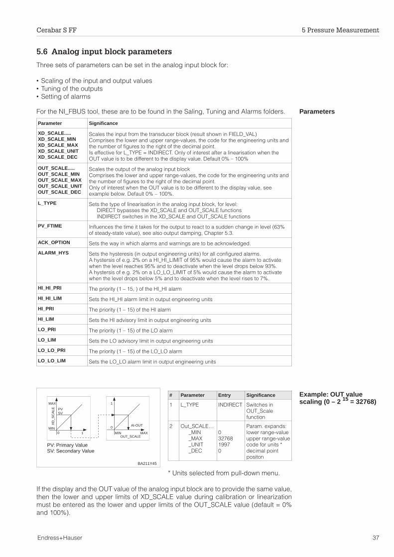
5.6 Analog input block parameters
Three sets of parameters can be set in the analog input block for:
• Scaling of the input and output values• Tuning of the outputs• Setting of alarms
ParametersFor the NI_FBUS tool, these are to be found in the Saling, Tuning and Alarms folders.
Example: OUT valuescaling (0 – 2 15 = 32768)
# Parameter Entry Significance
1 L_TYPE INDIRECT Switches inOUT_Scalefunction
2 Out_SCALE…_MIN_MAX_UNIT_DEC
03276819970
Param. expands:lower range-valueupper range-valuecode for units *decimal pointpositon
* Units selected from pull-down menu.
If the display and the OUT value of the analog input block are to provide the same value,then the lower and upper limits of XD_SCALE value during calibration or linearizationmust be entered as the lower and upper limits of the OUT_SCALE value (default = 0%and 100%).
Scales the input from the transducer block (result shown in FIELD_VAL)Comprises the lower and upper range-values, the code for the engineering units andthe number of figures to the right of the decimal point.Is effective for L_TYPE = INDIRECT. Only of interest after a linearisation when theOUT value is to be different to the display value. Default 0% – 100%
Scales the output of the analog input blockComprises the lower and upper range-values, the code for the engineering units andthe number of figures to the right of the decimal point.Only of interest when the OUT value is to be different to the display value, seeexample below. Default 0% – 100%.
L_TYPE Sets the type of linearisation in the analog input block, for level:DIRECT bypasses the XD_SCALE and OUT_SCALE functionsINDIRECT switches in the XD_SCALE and OUT_SCALE functions
PV_FTIME Influences the time it takes for the output to react to a sudden change in level (63%of steady-state value), see also output damping, Chapter 5.3.
ACK_OPTION Sets the way in which alarms and warnings are to be acknowledged.
ALARM_HYS Sets the hysteresis (in output engineering units) for all configured alarms.A hystersis of e.g. 2% on a HI_HI_LIMIT of 95% would cause the alarm to activatewhen the level reaches 95% and to deactivate when the level drops below 93%.A hystersis of e.g. 2% on a LO_LO_LIMIT of 5% would cause the alarm to activatewhen the level drops below 5% and to deactivate when the level rises to 7%.
HI_HI_PRI The priority (1 – 15, ) of the HI_HI alarm
HI_HI_LIM Sets the HI_HI alarm limit in output engineering units
HI_PRI The priority (1 – 15) of the HI alarm
HI_LIM Sets the HI advisory limit in output engineering units
LO_PRI The priority (1 – 15) of the LO alarm
LO_LIM Sets the LO advisory limit in output engineering units
LO_LO_PRI The priority (1 – 15) of the LO_LO alarm
LO_LO_LIM Sets the LO_LO alarm limit in output engineering units
PVSV
AI-OUTXD
_SC
ALE
MIN0
0
1
1
MIN
MAX
MAXOUT_SCALE
PV: Primary ValueSV: Secondary Value
BA211Y45
Cerabar S FF 5 Pressure Measurement
Endress+Hauser 37
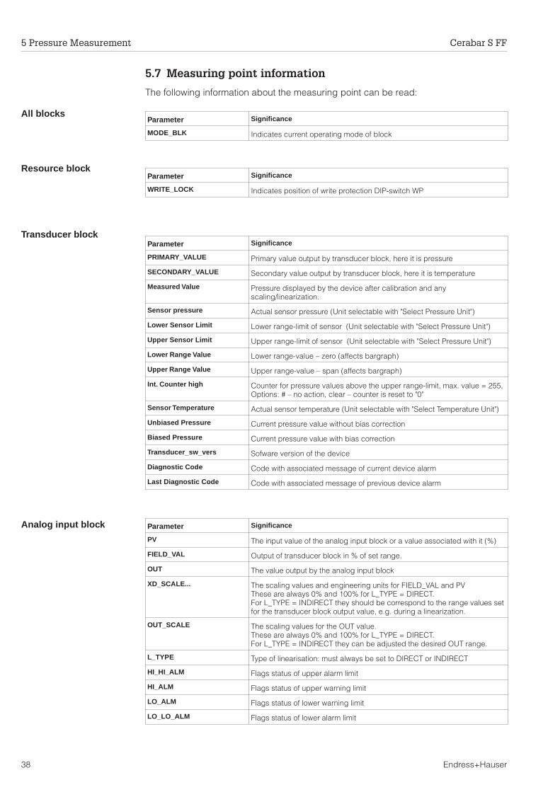
5.7 Measuring point information
The following information about the measuring point can be read:
All blocks
Resource block
Transducer block
Analog input block Parameter Significance
PV The input value of the analog input block or a value associated with it (%)
FIELD_VAL Output of transducer block in % of set range.
OUT The value output by the analog input block
XD_SCALE... The scaling values and engineering units for FIELD_VAL and PVThese are always 0% and 100% for L_TYPE = DIRECT.For L_TYPE = INDIRECT they should be correspond to the range values setfor the transducer block output value, e.g. during a linearization.
OUT_SCALE The scaling values for the OUT value.These are always 0% and 100% for L_TYPE = DIRECT.For L_TYPE = INDIRECT they can be adjusted the desired OUT range.
L_TYPE Type of linearisation: must always be set to DIRECT or INDIRECT
HI_HI_ALM Flags status of upper alarm limit
HI_ALM Flags status of upper warning limit
LO_ALM Flags status of lower warning limit
LO_LO_ALM Flags status of lower alarm limit
Parameter Significance
WRITE_LOCK Indicates position of write protection DIP-switch WP
Parameter Significance
MODE_BLK Indicates current operating mode of block
Parameter Significance
PRIMARY_VALUE Primary value output by transducer block, here it is pressure
SECONDARY_VALUE Secondary value output by transducer block, here it is temperature
Measured Value Pressure displayed by the device after calibration and anyscaling/linearization.
Sensor pressure Actual sensor pressure (Unit selectable with "Select Pressure Unit")
Lower Sensor Limit Lower range-limit of sensor (Unit selectable with "Select Pressure Unit")
Upper Sensor Limit Upper range-limit of sensor (Unit selectable with "Select Pressure Unit")
Lower Range Value Lower range-value – zero (affects bargraph)
Upper Range Value Upper range-value – span (affects bargraph)
Int. Counter high Counter for pressure values above the upper range-limit, max. value = 255,Options: # – no action, clear – counter is reset to "0"
Sensor Temperature Actual sensor temperature (Unit selectable with "Select Temperature Unit")
Unbiased Pressure Current pressure value without bias correction
Biased Pressure Current pressure value with bias correction
Transducer_sw_vers Sofware version of the device
Diagnostic Code Code with associated message of current device alarm
Last Diagnostic Code Code with associated message of previous device alarm
5 Pressure Measurement Cerabar S FF
38 Endress+Hauser
6 Level Measurement
This chapter describes the parameters which must be enterd to commision a Cerabar Sfor level measurement. This chapter contains the following information:
• Calibration via tool• Empty/ Full calibration• Dry calibration• Damping• Locking/unlocking of the manufacturer's-specific parameters• Analog input block parameter• Measuring point information
Note!Additional functions that are required for level measurement, e.g. linearization can beaccessed only via a Foundation Fieldbus tool.
6.1 Calibration via a configuration tool
The calibration is made via a configuration tool (remote operation).
Parameter Significance
Lower RangeValue
Entry of pressure for lower range-value – zero(bargraph and pressure for "empty")
Upper RangeValue
Entry of pressure for upper range-value – span, max. turndown 20:1(bargraph and pressure for "full")
Set Lower RangeValue
Acting pressure is taken as lower range-value – zero(bargraph and pressure for "empty")
Set Upper RangeValue
Acting pressure is taken as upper range-value – span, max. turndown 20:1(bargraph and pressure for "full")
Set Bias Pressure Entry of bias pressure (affects display module and parameter "Biased Pressure" only)
Bias Pres Autom Acting pressure is taken as bias pressure (affects display module and parameter"Biased Pressure" only)
Set Output Damp. Entry of damping τ (0...40 s)
Select Press Unit Options pressure unit: mbar, bar, Pa, hPa, kPa, MPa, mm H2O, m H2O, in H2O,ft H2O, psi, g / cm2, kg / cm2, kgf / cm2, atm, lb / ft2, torr, mm Hg or in Hg.
Linearization Operating mode: "level linear" (level, volume and weight) or "level horizontal cylinder"(volume and weight)
Start Point Zero for output scaling (corresponds to lower range-value)
Full Scale Scale value for output scaling (corresponds to upper range-value)
Unit AfterLinearization
Selecting units for mesuring the level, volume or weight – the options depend on theoperating mode selected. The linearized value is shown in these units. Themeasured value is not converted into the new units.
Density Factor Density factor – Applications with media with a density not equal to 1 g/cm³.
Note!
Cerabar S FF 6 Level Measurement
Endress+Hauser 39
Density correction If the calibration has been made with water and the product changes at a later date, thecalibration values can be corrected by entering a density factor.
new densitydensity factor = current factor • –––––––––––
old density
Determining the densityfactor
Example: A tank is filled with water and calibrated. The density of the water (old density)is 1 g/cm3. Later the tank will be used as a storage tank and be filled with the actualmedium to be measured. The new density is 1.2 g/cm3. "Density Factory" still containsthe factory setting "1", i.e. the current factor is "1".
1.2 g / cm3
density factor = 1 • ––––––––––1 g / cm 3
# Parameter Entry Significance
1 Density Factor e.g. 1.2 Density correction
2 MeasuredValue
e.g.62.5 %
Corrected level
Result• The measured value in parameter "Mea-
sured Value" is divided by the densityfactor and is thus correct for the newproduct.
Note!The density factor directly affects the level measurement. If the product density changes,make sure that the density factor is updated before an existing linearization curve is used.
BA211Y48
Measurementwith productρ = 1.2
Calibrationwith waterρ = 1.0
Note!
6 Level Measurement Cerabar S FF
40 Endress+Hauser
6.2 Empty/full calibration
The empty/full calibration lays down the desired minimum and maximum levels formeasurement. The entries can be made in any units. There are two prerequisites:
• The Cerabar S has been mounted.• The tank can be filled.
"Level linear"# Parameter Entry Significance
1 DefaultValues
5140 Reset to factorysetting
2 Linerazition "levellinear"
Operating mode
3 The tank is empty (0...40 %)
4 Set LowerValue
Confirm Register pressure
5 Start Point e.g. 0 Current level =level for "empty"
6 The tank is full (60...100 %)
7 Set UpperValue
Confirm Register pressure
8 Full Scale e.g. 100 Current level =level for "full"
9 Unit After Lin e.g. % Select level units
Result• Level is displayed in "Measured Value"
"Level horizontalcylinder"
# Parameter Entry Significance
1 Default Value 5140 Reset to factorysetting
2 Linearization "levelhorizontalcylinder"
Operating mode
3 The tank is empty (0...40 %)
4 Set LowerValue
Confirm Register pressure
5 Start Point e.g. 2 Current level =level for "empty"
6 The tank is full (60...100 %)
7 Set UpperValue
Confirm Register pressure
8 Full Scale e.g. 100 Current level =level for "full"
9 Unit After Lin e.g. % Select level units
Result• Level is displayed in "Measured Value"
Unit After LinearizationThe units for level, volumetric or weight are selected with the parameter "Unit AfterLinearization". Selecting these units is only to help the operator. It has no effect on themain measured value in parameter "Measured Value".
Example: 55 % is shown as 55 hl after selcting the unit "hl".
BA211Y46
Full100 %
Empty0 %
Full100 %
Empty2 %
BA211Y47
Cerabar S FF 6 Level Measurement
Endress+Hauser 41
6.3 Dry calibration
The dry calibration is a calculated calibration, which can be made with an empty tank oron the test bench. The "empty" calibration point is normally at the sensor mounting point.If the measurement is to begin at another level, then this must be considered in thecalculation. The prerequisites for a dry calibration are:
• The empty and full levels are known.• The density factor is known.• The pressure for »empty« and »full« has been calculated (p = ρgh).
If the device has a display and the point of mounting is below the empty level, then abias pressure must be entered in "Set Bias Pressure" (position correction).
"Level linear"# Parameter Entry Significance
1 DefaultValue
5140 Reset tofactory setting
2 Select PressUnit
e.g. mbar Select pressureunit
3 Set BiasPressure
e.g. 100,= LowerRangeValue
For displaymodulebias pressure
4 Lower RangeValue
e.g. 100 Pressure for"empty"
5 Upper RangeValue
e.g. 400 Pressure for "full"
6 Linearization "levellinear"
Operating mode
7 Start Point e.g. 0 Level for "empty"
8 Full Scale e.g. 300 Level for "full"
9 Unit After Lin e.g. hl Select level units
Result:• Level is displayed in "Measured Value".
"Level horizontalcylinder"
# Parameter Entry Significance
1 DefaultValue
5140 Reset tofactory setting
2 Select PressUnit
e.g. mbar Select pressureunit
3 Lower RangeValue
e.g. 100 Pressure for"empty"
4 Upper RangeValue
e.g. 400 Pressure for "full"
5 Linearization "levelhorizontalcylinder"
Operating mode
6 Start Point e.g. 0 Level for "empty"
7 Full Scale e.g. 200 Level for "full"
8 Unit After Lin e.g. hl Select level units
Result:• Level is displayed in "Measured Value".
Check after installation After a calibration, the first filling of the tank should be carefully observed, so that anyerrors or uncertainties are immediately detected.
1 m
3 m
0 m
4 m
BA211Y49
Upper RangeValue
Full Scale
Lower RangeValue
Start Point
2 m
BA211Y50
Upper RangeValue
Full Scale
Lower RangeValue
Start Point
6 Level Measurement Cerabar S FF
42 Endress+Hauser
6.4 Damping
Output dampingThe damping influences the time it takes for the display in "Measured Value" to react toa change in pressure.
# Parameter Entry Significance
1 Set OutputDamping
e.g. 30 Damping intransducer blockincreased to 30 s
Note!Both the transducer block output and the analog input block can be damped. Werecommend that the damping be set in the transducer bloch during commissioning andincreased if necessary in the analog input block during normal operation. This preventsthe device switching to "Out of Service" when the parameter is edited.
6.5 Maximum pointer function
Maximum pointerfunction
The maximum pointer function displays the maximum and minimum pressure andtemperature measured since the last pointer reset.
The units for pressure and temperature are selected with the parameter "Select PressureUnit" and "Select Temperature Unit" respectively. Please note that any change in thepressure units affects all pressure entries.
0 τ 2τ 3τ
63 %
100 %
BA211Y41
pressure
signal
time
Parameter Signifiance
Min. Pressure Minimum pressure, Reset via the option "reset" to the acting pressure valueusing the parameter "Reset Min Pres Peak Hold"
Max. Pressure Maximum pressure, Reset via the option "reset" to the acting pressurevalue using the parameter "Reset Max Pres Peak Hold"
Min. Temperature Minimum temperature, Reset via the option "reset" to the actingtemperature using the parameter "Reset min Peak Hold"
Max.Temperature Maximum temperature, Reset via the option "reset" to the actingtemperature using the parameter "Reset max Peak Hold"
Note!
Cerabar S FF 6 Level Measurement
Endress+Hauser 43
6.6 Locking/unlocking
After all parameters have been entered, the manufacturer's-specific parameters can belocked.
• via the keys +Z, –Z, +S and –S or• via the parameter "Security Looking" by entering a three digit code ≠ 130.
(130 is the code for unlocking the parameters)
This protects the measuring point from accidental and unauthorised entries.
Keys # Key Entry
1 Lock operation:Press +Z and -S simultaneously once
2 Unlock operation:Press -Z and +S simultaneously once
Parameter # Parameter Entry Significance
1 SecurityLooking
e.g. 131 Parameterslocked
2 SecurityLooking
130 Parametersunlocked
The table below summarises the locking function.
– –
+
Z S
+
– –
+ +
Z S – –
+
Z S
– –
+
Z S
+
+
BA
211Y
42
Locking
Unlocking
Locking with keys has priority
Locking via Display/reading ofparameters
Changing/writing via Unlocking via
keys communication keys communication
Keys yes no no yes no
Parameter yes no no yes yes
6 Level Measurement Cerabar S FF
44 Endress+Hauser
6.7 Analog input block parameters
Three sets of parameters can be set in the analog input block for:
• Scaling of the input and output values• Tuning of the outputs• Setting of alarms
ParametersFor the NI_FBUS tool, these are to be found in the Saling, Tuning and Alarms folders.
Example: OUT valuescaling (0 – 2 15 = 32768)
# Parameter Entry Significance
1 L_TYPE INDIRECT Switches inOUT_Scalefunction
2 Out_SCALE…_MIN_MAX_UNIT_DEC
03276819970
Param. expands:lower range-valueupper range-valuecode for units *decimal pointpositon
* Units selected from pull-down menu.
If the display and the OUT value of the analog input block are to provide the same value,then the lower and upper limits of the XD_SCALE value during calibration or linearizationmust be entered as the lower and upper limits of the OUT_SCALE value (default = 0%and 100%).
Scales the input from the transducer block (result shown in FIELD_VAL)Comprises the lower and upper range-values, the code for the engineering units andthe number of figures to the right of the decimal point.Is effective for L_TYPE = INDIRECT. Only of interest after a linearization when theOUT value is to be different to the display value. Default 0% – 100%
Scales the output of the analog input blockComprises the lower and upper range-values, the code for the engineering units andthe number of figures to the right of the decimal point.Only of interest when the OUT value is to be different to the display value, seeexample below. Default 0% – 100%.
L_TYPE Sets the type of linearisation in the analog input block, for level:DIRECT bypasses the XD_SCALE and OUT_SCALE functionsINDIRECT switches in the XD_SCALE and OUT_SCALE functions
PV_FTIME Influences the time it takes for the output to react to a sudden change in level (63%of steady-state value), see also output damping, Chapter 6.4.
ACK_OPTION Sets the way in which alarms and warnings are to be acknowledged.
ALARM_HYS Sets the hysteresis (in output engineering units) for all configured alarms.A hystersis of e.g. 2% on a HI_HI_LIMIT of 95% would cause the alarm to activatewhen the level reaches 95% and to deactivate when the level drops below 93%.A hystersis of e.g. 2% on a LO_LO_LIMIT of 5% would cause the alarm to activatewhen the level drops below 5% and to deactivate when the level rises to 7%.
HI_HI_PRI The priority (1 – 15, ) of the HI_HI alarm
HI_HI_LIM Sets the HI_HI alarm limit in output engineering units
HI_PRI The priority (1 – 15) of the HI alarm
HI_LIM Sets the HI advisory limit in output engineering units
LO_PRI The priority (1 – 15) of the LO alarm
LO_LIM Sets the LO advisory limit in output engineering units
LO_LO_PRI The priority (1 – 15) of the LO_LO alarm
LO_LO_LIM Sets the LO_LO alarm limit in output engineering units
PVSV
AI-OUTXD
_SC
ALE
MIN0
0
1
1
MIN
MAX
MAXOUT_SCALE
PV: Primary ValueSV: Secondary Value
BA211Y45
Cerabar S FF 6 Level Measurement
Endress+Hauser 45
6.8 Measuring point information
The following information about the measuring point can be read:
All blocks
Resource block
Transducer block
Analog input block
Parameter Significance
WRITE_LOCK Indicates position of write protection DIP-switch WP
Parameter Significance
MODE_BLK Indicates current operating mode of block
Parameter Significance
PRIMARY_VALUE Primary value output by transducer block, here it is linearization value
SECONDARY_VALUE Secondary value output by transducer block, here it is temperature
Measured Value Pressure displayed by the device after calibration and anyscaling/linearization.
Sensor pressure Actual sensor pressure (Unit selectable with "Select Pressure Unit")
Lower Sensor Limit Lower range-limit of sensor (Unit selectable with "Select Pressure Unit")
Upper Sensor Limit Upper range-limit of sensor (Unit selectable with "Select Pressure Unit")
Lower Range Value Lower range-value – zero (affects bargraph and linearization)
Upper Range Value Upper range-value – span (affects bargraph and linearization)
Int. Counter high Counter for pressure values above the upper range-limit, max. value = 255,Options: # – no action, clear – counter is reset to "0"
Sensor Temperature Actual sensor temperature (Unit selectable with "Select Temperature Unit")
Start Point Zero for output scaling (correponds to lower range-value)
Full Scale Scale value for output scaling (corresponds to upper range-value)
Unbiased Pressure Current pressure value without bias correction
Biased Pressure Current pressure value with bias correction
Transducer_sw_vers Sofware version of the device
Diagnostic Code Code with associated message of current device alarm
Last Diagnostic Code Code with associated message of previous device alarm
Parameter Significance
PV The input value of the analog input block or a value associated with it (%)
FIELD_VAL Output of transducer block in % of set range.
OUT The value output by the analog input block
XD_SCALE... The scaling values and engineering units for FIELD_VAL and PVThese are always 0% and 100% for L_TYPE = DIRECT.For L_TYPE = INDIRECT they should be correspond to the range values setfor the transducer block output value, e.g. during a linearisation.
OUT_SCALE The scaling values for the OUT value.These are always 0% and 100% for L_TYPE = DIRECT.For L_TYPE = INDIRECT they can be adjusted the desired OUT range.
L_TYPE Type of linearisation: must always be set to DIRECT or INDIRECT
HI_HI_ALM Flags status of upper alarm limit
HI_ALM Flags status of upper warning limit
LO_ALM Flags status of lower warning limit
LO_LO_ALM Flags status of lower alarm limit
6 Level Measurement Cerabar S FF
46 Endress+Hauser
7 Diagnosis and Trouble-Shooting
7.1 Diagnosis of errors and warnings
ErrorsWhen the Cerabar S detects an error:
• An error code is transmitted along with the measured value.• If the display is present, the error code is displayed and flashes.• The current error code is displayed in parameter "Diagnostic Code", the last error
code in parameter "Last Diagnostic Code".
WarningsWhen the Cerabar S detects a warning:
• An error code is transmitted along with the measured value: the Cerabar Scontinues measuring.
• The current error code is displayed in parameter "Diagnostic Code", the last errorcode in parameter "Last Diagnostic Code".
If several errors occur simultaneously, then they are displayed in sequencecorresponding to the priority of the error.
Code Type Source and remedy
E 101 Error Electronic instrument error– Remedy by Endress+Hauser Service
E 102 Warning Electronic instrument error with the maximum counter function– Carry out reset (Code 5140), recalibrate the instrument
E 103 Error Initialising in progress– Wait until the procedure is completed
E 104 Warning Sensor calibration– Recalibrate sensor
E 110 Error Check sum error– Carry out reset (Code 5140), the error remains– Remedy by Endress+Hauser Service
E 111,E 112,E 113,E 114
Error Electronic instrument error– Remedy by Endress+Hauser Service
E 115 Error Sensor overpressure– Remains until overpressure is no longer present
E 120 Error Sensor underpressure– Remains until underpressure is no longer present
E 610 Error Calibration error, same pressure value for "Lower Range Value" and "UpperRange Value"– Check the calibration
E 620 Warning Measured value outside range
Cerabar S FF 7 Diagnosis and Trouble-Shooting
Endress+Hauser 47
7.2 Simulation
Simualtion of theOUT value
The OUT value can also be simulated in the analog input block:
1. Check that the simulation is enabled at the DIP-switch WP, see Chapter 3.2.
2. Click on the SIMULATE parameter:– Set to enable– Enter a simulation value– Click on WRITE CHANGES button– Check the effect on the OUT value and any following links.
3. Disable the SIMULATE parameter.
During simulation, the BLOCK_ERROR shows the status "simulation active".
7.3 Reset
By entering a code, the entries in the manufacturer's-specific parameters are resetcompletely to factory settings.
# Parameter Entry Significance
1 DefaultValues
5140 Reset to factorysetting
The following table provides a summary of factory settings. (* = display value)
Parameter Default Value
Measured Value *
Lower Range Value 0.0
Upper Range Value = High SensorLimit
Set Lower Range Value
Set Upper Range Value
Set Bias Pressure 0.0
Bias Pressure Automatically
Set Output Damping 0.0
Select Pressure Unit bar
Diagnostic Code * 0
Last Diagnostic * 0
Clear Last Diagnostic Code
Transducer_sw_vers *
Min. Pressure * Act. pressure
Reset Min. Pres Peak Hold
Max. Pressure * Act. pressure
Reset Max. Pres Peak Hold
Integer Counter high * 0
Sensor Temperature * Act. temperature
Min. Temperature * Act. temperature
Reset min Temp. Peak Hold
Max. Temperature * Act. temperature
Reset max Temp. Peak Hold "Pressure linear"
Parameter Default Value
Default Values
Linearization(operating mode)
Start Point 0.0
Full Scale 100.0
Unit After Liniarization bar
Density Factor 1.0
Creep Flow Suppression 0.0
Low Sensor Calibration = Low Sensor Limit
High Sensor Calibration = High SensorLimit
Low Sensor Limit *
High Sensor Limit *
Sensor Pressure * Act. sensor press.
Temperature Unit °C
Unbiased Pressure * Act. sensor press.
Biased Pressure * Act. sensor press.
Security Locking 130
Serial-No. SENS. *
Process Conn. P+ special
Process Conn. P– special
Gasket special
Process Diaphram. special
Fill Liquid special
7 Diagnosis and Trouble-Shooting Cerabar S FF
48 Endress+Hauser
8 Maintenance and Repair
8.1 Repair
If the Cerabar S must be sent to Endress+Hauser for repair, then a note should beenclosed containing the following information.
• An exact description of the application• The chemical and physical characteristics of the product.• A brief description of the error.
Before sending in the Cerabar S to Endress+Hauser for repair, please take the followingprotective measures:
• Remove all traces of the product.This is particularly important if the product is dangerous to health, e.g. corrosive,poisonous, carcinogenic, radioactive, etc.
• We do request that no instrument should be returned to us without all dangerousmaterial being completely removed first as it can, e.g. penetrate into fissures ordiffuse through plastic.
Caution!Instruments with certificates of conformity or design approval must be sent in for repairas complete units only.
Caution!
Cerabar S 8 Maintenance and Repair
Endress+Hauser 49
8.2 Mounting the display
Mounting the display • Switch off power supply.• Open the cover to the display
compartment (use a cover with a sightglass after mounting the display).
• Insert the plug of the display in thecentre jack. Note the coding of the plugand jack.
• Attach display.The display can be rotated through 90°.
• Screw down the cover.
Removing the display • Switch off power supply.• Open the cover to the display
compartment.• Press the down the latch at the
front.• Tilt the display forward and remove.• Remove plug.• Screw down the cover.
0 - 10 BAR ABS
0123456
78
9ABCD
EF
0123456
78
9ABCD
EF
4...20 mA
4...20 mA
TestTest
12
3
Switch offpower supply
BA211Y510123456
78
9ABCD
EF
0123456
78
9ABCD
EF
0 - 25 mbar
BA211Y52
0123456
78
9ABCD
EF
0123456
78
9ABCD
EF
0123456
78
9ABCD
EF
0123456
78
9ABCD
EF0 - 25 mbar
0 - 25 mbar
0 - 25 mbar
0 - 25 mbar
4x
90°
BA211Y53
0123456
78
9ABCD
EF0123456
78
9ABCD
EF
0123456
78
9ABCD
EF0 - 25 mbar 0 - 25 mbar
BA211Y54
Switch offpower supply
8 Maintenance and Repair Cerabar S
50 Endress+Hauser
8.3 Changing the sensor module and electronics
Warning!The sensor module and electronics should only be replaced by E+H Service when usingthe instrument in EEx d and EEx ia areas.The Cerabar S must be sent back to E+H Service as a complete unit.
Caution!The electronic module is an electronic component. Electrostatic discharge can affect theoperation of the instrument or cause damage to its electronic components. Contactshould be made with a grounded object before handling the electronic module. Switchoff power supply.
Changing the electronicsRemoval• Open the cover to the display compartment• Remove the display• Undo the two screws on the holding ring and remove• Remove the plug from the electronic module• Remove the electronic module
Mounting• Insert the electronic module• Mount the holding ring• Insert the plug, noting size and coding• Attach display of cover and screw down the cover to the display compartment
Changing the sensormoduleRemoval
• Remove the complete electronics and electronic box from the housing (see above).• Position the bracket and smooth face on the sensor module parallel to each other.
Remove the stud, undo the screw and lift out the bracket. When unscrewing thesensor module, carefully rotate the cable with it.
Mounting• Insert the cable with plug into the display compartment.• Screw in the sensor module right to the stop, taking care to turn the cable with it.• To ensure that the Cerabar S can be fully turned when mounted, turn the unit in the
other direction by one complete turn.• Position the bracket and smooth face parallel to the sensor module.• Secure the bracket with the stud and screw.• Mount the electronics and electronic box and insert the plug, noting size and coding.
4...20 mA
Test
12
3
0 - 10 BAR ABS
0123456
78
9ABCD
EF
Switch offpower supply
Holding ring
Electronic moduleCaution!Electronic component
Sensor module
Electronics box
BA211Y55
Bracket
Stud
Captive screwconnected withstud and nut
Caution!
Cerabar S 8 Maintenance and Repair
Endress+Hauser 51
8.4 Changing the seal
The seal in contact with the medium inside the adapter of the Cerabar S PMC 731 canbe replaced. Except for the PTFE seal (Structure D), all seals can thus be interchangedas required. The different temperature limits should thus be observed for individualmaterials.
Changing the seal• Loosen the screws on the retaining ring
of the adapter.• Remove the retaining ring and adapter.• Replace seal.
The surfaces each side of the seal andthe seal itself must be free from fibresand dirt.
• Secure the adapter with the retainingring and screws
Changing the PTFE seal• Loosen the screws on the retaining ring
of the adapter.• Remove the retaining ring and adapter.• Replace seal.
The surfaces each side of the seal andthe seal itself must be free from fibresand dirt.
• Secure the adapter with the retainingring and screws.
• Warm the instrument to 80…85°C andmaintain at this temperature for about 2hours to condition the seal.
8.5 Replacement parts
The diagram on the next page shows all replacement parts, together with their ordernumbers, which can be ordered from Endress+Hauser.
When ordering replacement parts, please note the following:• If parts given in the order code are to be replaced, then it must be ensured that the
order code (instrument designation) on the nameplate is still valid.• If the instrument designation on the nameplate has changed then a modified
nameplate must also be ordered. The information about the new instrument mustthen be entered on the modified nameplate. This must then be attached to thehousing of the Cerabar S.
• It is not possible to convert a standard instrument into an Ex instrument by replacingits parts.
0123456
78
9ABCD
EF
4...20 mA
Test
12
3
Seal
Adapter
Holding ringwith screws
BA
211Y
56
Seal Lower temperature limit
1 FPM, Viton –20 °C
6 FPM, Viton grease-free –10 °C
A FPM, Viton oil and grease-free for oxygen –10…+60 °C
8 NBR (DVGW) –20…+80 °C
2 NBR –20 °C
7 FFKM Kalrez +5 °C
4 EPDM –40 °C
D PTFE and Hastelloy C 4 –20…+85 °C
8 Maintenance and Repair Cerabar S
52 Endress+Hauser
4...2
0 m
A
4...2
0 m
A
Test
12
3
0 - 10 BA
R ABS
0 - 10 BA
R ABS
0123456789ABC
DEF 0123456789ABC
DEF
Cov
er w
ith s
ight
gla
ssst
anda
rd, i
ntrin
sica
llysa
fein
trin
sica
llysa
fe /
FM
/ C
SA
EE
x d/
Cen
elec
/FM
/CS
A
Mou
ntin
g se
t, cp
l.91
9 80
6 -
0000
Cov
erst
anda
rd 9
42 8
51 -
020
1E
Ex
d
942
851
- 1
201
LC d
ispl
ay, c
pl.
942
037
- 00
00
O-r
ing
61.6
x 2
.62
013
982
- 00
00
Rin
g91
9 36
3 -
0000
Ex
d m
odul
e53
5 61
0 -
0000
(not
for
PR
OF
IBU
S)
Ele
ctro
nics
, com
plet
eC
ertif
icat
es E
Ex
ia, E
Ex
d, F
M, C
SA
INT
EN
SO
R
528
400
- 1
204
HA
RT
528
400
- 1
104
poly
silic
one
mea
surin
g ce
llfo
r P
MP
731
cera
mic
mea
surin
g ce
llsfo
r P
MC
731
Par
t Nos
. see
spar
e pa
rts
for
mea
surin
gce
lls
Par
t Nos
. see
spar
e pa
rts
for
mea
surin
gce
lls
Flu
shdi
aphr
agm
Ver
sion
sF
M is
,CS
A is
,C
enel
ec E
Ex
d
Ver
sion
sS
tand
ard,
Cen
elex
EE
x ia
/ E
Ex
d,F
M is
,FM
xp,
CS
A is
,CS
A x
p
Ver
sion
sS
tand
ard,
EE
x ia
, CS
A is
,FM
is(n
ot fo
r E
Ex
d !)
Inte
rcha
ngea
ble
thre
aded
bos
s,se
e sp
are
part
s fo
r m
easu
ring
cells
Lim
it st
op, c
pl.
919
923
- 00
00
Term
inal
str
ipst
anda
rd
543
170
- 3
000
PR
OF
IBU
S54
3 17
0 -
2100
Pg
13.5
016
319
- 00
00
Thr
ead
adap
tor
M26
x 1
.5(m
ustb
e or
der
with
a n
ew h
ousi
ngan
d th
en g
lued
in w
ith L
octit
e)P
g 13
. 5
91
9 58
4 -
0000
M20
x 1
.5
919
584
- 00
011/
2"-N
PT
9
19 5
84 -
000
2G
1/2
"
9
19 5
84 -
000
3
Hou
sing
T4
prem
ount
edst
anda
rd (
Pg1
3.5)
542
852
- 5
111
stan
dard
(M
26)
5
42 8
52 -
511
2P
RO
FIB
US
(M26
) 54
2 85
2 -
5132
Fie
ldbu
s (M
26)
5
200
6043
Ele
ctro
nics
box
919
362
- 00
10
O-r
ing
013
982
- 00
00
Cov
erst
anda
rd 9
42 8
51 -
020
1E
Ex
d
942
851
- 1
201
PR
OF
IBU
SPA
ele
ctro
nics
543
024
- 00
00F
ield
bus
Foun
datio
n el
ectr
onic
s52
00 6
044
Rin
g fo
rPA
ele
ctro
nics
91
9 36
3 -
1000
Fie
ldbu
s el
ectr
onic
s 52
00 6
045
Isol
atio
n pl
ate
(with
out L
C-
disp
lay
only
)94
2 82
1 -
0000
1
1T
he p
rem
ount
ed h
ousi
ngco
nsis
t of p
reas
sem
b ly:
• K
ey in
sert
ion
• Te
rmin
al s
trip
• E
arth
cla
mps
942
856
- 02
0094
2 85
6 -
0210
942
856
- 12
00
BA
211Y
57
Cerabar S 8 Maintenance and Repair
Endress+Hauser 53
9 Technical DataGeneral information Manufacturer Endress+Hauser
Instrument Pressure transmitterDesignation Cerabar S PMC 631, PMP 635, PMC 731, PMP 731Technical documentationVersionTechnical data
BA 211P/00/en04.00DIN 19259
Input Measured variables Absolute and gauge pressure in gases, vapours, liquidsMeasuring ranges As stated on nameplate
Output Output signal Digital communication signal, Foundation Fieldbus protocolFF function Publisher-SubscriberTransmission rate 31.25 kBit/sSignal on alarm Signal: Status bit set, last valid measured value will be held
Display module: error codeDamping 0…40 s via configuration toolCommunication resistance Foundation Fieldbus termination resistor
Accuracy Reference conditions DIN IEC 770 TU=25 °CAccuracy data adopted after entering "Low sensor calibration" and "Highsensor calibration" for lower range value and upper range value
Linearity including hysteresisand repeatability based on thelimit point method to IEC 770
to TD 10:1: ±0.1 % (* ±0.2 %) of set spanfor TD 10:1 to 20:1:±0.1 % (* ±0.2 %) x [nominal value/(set span x 10)]
For small absolute pressureranges more detailedinformation on linearity isrequired. This is specified bythe smallest possiblemeasurement error which canbe supplied by the DKDcalibration centre.
Absolute: for >30 mbar <100 mbar span: ±0.3 %for ≤ 30 mbar: ±1 %of set span
Thermal changes(applies to transmitters withoutdiaphragm seals or capillarytubing)
for –10…+60 °C: ±(0,1 % x TD + 0,1 %)for –40…–10 °C, +60 °C…+85 °C: ±(0.2 % x TD + 0.2 %)with reference to the set span
Thermal changes forCerabar S with PTFE sealPMC 731 - # # ## # # # ## D
for –20…+85 °C: ±(0.2 % x TD + 0.4 %): 0.1 bar±(0.2 % x TD + 0.2 %): 0.4 bar, 2 bar±(0.1 % x TD + 0.1 %)10 bar, 40 bar
Temperature coefficient(for the set span; applies totransmitters withoutdiaphragm seals or capillarytubing)
Zero signal and output span:±0.02 % of nominal value / 10 K at –10…+60 °C±0.05 % of nominal value / 10 K at –40…–10 °C and +60…+85 °C
Temperature coefficient forCerabar S with PTFE sealPMC 731 - # # ## # # # ## D
Zero signal and output span:±0.05 % of nominal value / 10 K at –20…+85 °C
Settling time Ceramic measuring cell: ± 500 ms, metal measuring cell: ±400 msRise time 150 ms (T90 time)Long-term driftwith reference to span
0.1 year
Explanation of terms:Turndown (TD) =Nominal value / set span
Example: Nominal value = 2 barset span = 0.9 bar
* Values for instruments withdiaphragm seals PMC 631,PMP 635 are identified by *
-1 0 0.9 2
Nominal value
set span
9 Technical Data Cerabar S FF
54 Endress+Hauser
Process conditions Process temperature –40…+100 °C (for EEx see Certificate of Conformity)Ambient temperature –40…+85 °C (for EEx see Certificate of Conformity)Ambient temperature range –40…+100 °C (for EEx see Certificate of Conformity)Storage temperature –40…+100 °C (for EEx see Certificate of Conformity)Electromagnetic compatibility Interference emission to EN 61 326 electrical equipment B
Interference immunity to EN 61 326 Annex A (industrial) andNAMUR directive NE 21,Interference immunity to EN 61 000-4-3: 30 V/mUse twisted screened two-wire cabling.
Protection IP 65Climatic class 4K4H to DIN EN 60721-3
Mechanical construction Dimensions See Fig. 10.1 and 10.2 as well as TI 216P and 217PHousing Housing can be rotated,
Separate electronic and connection compartments,
Optional electrical connection via Pg 13.5 with cable gland or M 20x1.5,G ½, ½ NPT thread,Terminal connection for cable cross-section 0.5…2.5 mm
Process connections All common thread and diaphragm seal versionsMaterialsHousing Cast aluminium housing with protective polyester-based powder coating
RAL 5012 (blue), cover RAL 7035 (grey), seawater resistant, seawaterspray test DIN 50021 (504 h) passed
O-ring for sealing cover NBRMounting accessories Bracket for pipe and wall mounting 1.4301 (AISI 304)Filling fluid in diaphragm sealsPMC 631, PMP 635
Silicone oil, vegetable oil, glycerine, high-temperature oil, Fluorolobegrease-free for oxygen
Measuring cellOil filling PMC 731
PMP 731None, dry sensorOptional silicone or inert oil (Voltalef) for oxygen
Display and operating interface Display (optional) Four-character LC display, with segment display of signal currentOperation Via four keys Z–, Z+, S–, S+Remote operation Via interface card H1 direct connection to PC with operating program or
via Link and interface card H1 connection to PC with operating programCommunication interface Foundation Fieldbus
Power supply Power supply voltage Standard: 9…32 V DC; EEx: 9…24 V DCCurrent consumption 10.5 mA ±1 mAPower up current Corresponds to Table 4, IEC 1158-2
Cerabar S FF 9 Technical Data
Endress+Hauser 55
DimensionsCerabar S
Further information on dimensions of the various versions is found in TI 216P and 217P.The maximum installation height is given in the product summaries on the followingpages.
0 - 10 bar
AB
A21
1Y61
0 - 10 bar
ENDRESS+HAUSERCERABAR
Order Code xxxxxxxxxxxxxxSer.-No. x xx xxxx
P –1…2 barP Span 100 mbarminPmax 20 bar4 . . . 20 mA HART U 10,5…45 V
Mat. 1.4571 / AL2O3 / FPM
CERABARKEMA Nr. Ex-94.D.8801
Prüfer:Datum:
EEx ia IIC T6,
C 11,2 nF, L 0,2 mHU 30 V, I 300 mA, P 1 WEEx ia IIC T4,
i i
-40°C T 40°CA-40°C T 70°CA
Cal./Adj.
Z S
112
98(without display)
135
104
Process connections are availablefor all common threads
Connection area Electronics compartment
18
M5
BA
211Y
59
Figure 9.1Cerabar PMC 731/PMP 731
0 - 10 bar
A
BA
211Y
60
Figure 9.2left:Cerabar S PMC 631with dairy threadright:Cerabar S PMP 635 with flange.See TI 216P and TI 217P for otherprocess connections