Affix label with Candidate Code Number here.If no label, enter candidate Number if known
No. 9196
REGISTRATION EXAMINATION, NOVEMBER 2016CERTIFYING GASFITTER
QUESTION AND ANSWER BOOKLET
Time allowed THREE hours
INSTRUCTIONS
Check that the Candidate Code Number on your admission slip is the same as the number on the label at the top of this page.
Do not start writing until you are told to do so by the Supervisor.
Total marks for this examination: 100.
The pass mark for this examination is 60 marks.
Write your answers and draw your sketches in this booklet. If you need more paper, use pages 18–21 at the back of this booklet. Clearly write the question number(s) if any of these pages are used.
All working in calculations must be shown.
Candidates are permitted to use the following in this examination:
Gas rate (m3/h) = volume (m3) × 3600 time (seconds)
Certifying Gasfitter 9196, November 2016 1
SECTION A
QUESTION 1
List THREE Acts of Parliament that have specific references to gasfitting.
1
2
3
Total 3 marks
Certifying Gasfitter 9196, November 2016 2
QUESTION 2
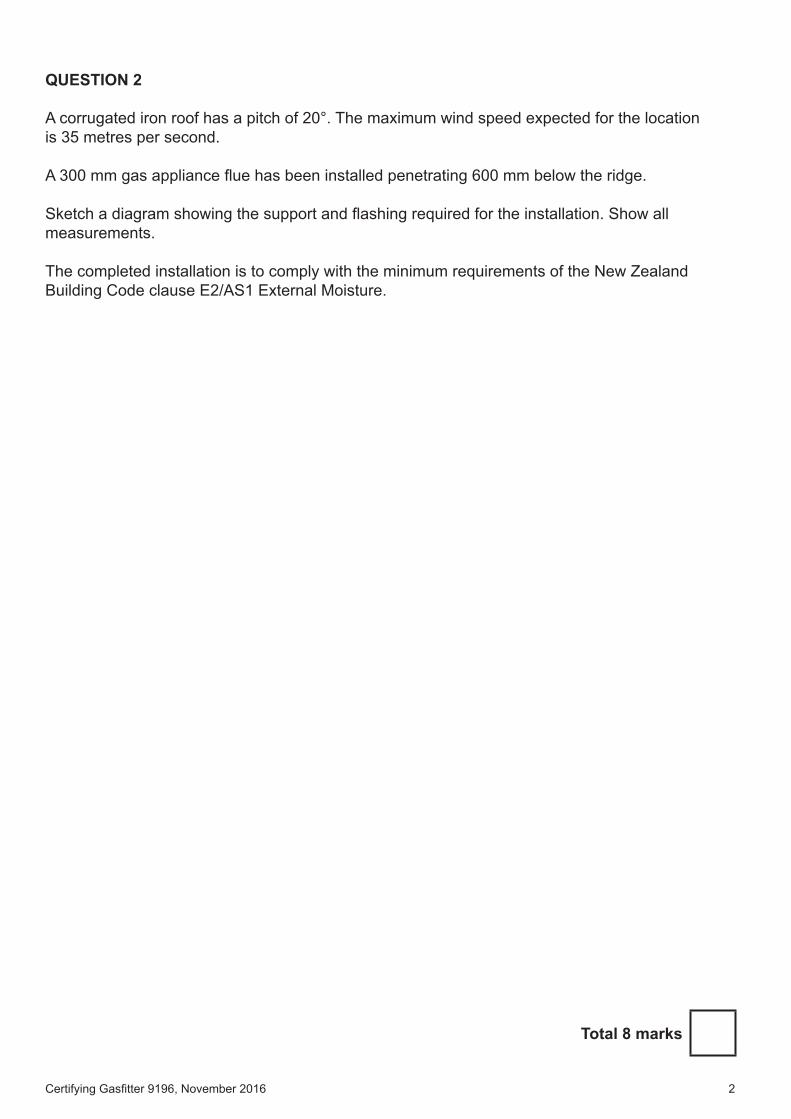
A corrugated iron roof has a pitch of 20°. The maximum wind speed expected for the location is 35 metres per second.
A 300 mm gas appliance flue has been installed penetrating 600 mm below the ridge.
Sketch a diagram showing the support and flashing required for the installation. Show all measurements.
The completed installation is to comply with the minimum requirements of the New Zealand Building Code clause E2/AS1 External Moisture.
Total 8 marks
Certifying Gasfitter 9196, November 2016 3
QUESTION 3
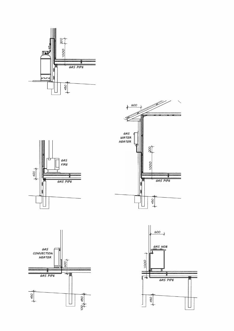
A customer has requested that gas appliances be installed in his new house. A plan and elevations of the gas installation for the house are given in the Resource Booklet.
The customer has requested that the installation pipework be made of a flexible composite pipe material that he has selected.
To pipe size the installation, the Composite Pipe Sizing Guide and the Composite Pipe Sizing Chart will be required. Both of these documents can be found in the Resource Booklet.
Use the following information and the Resource Booklet to complete the tables below.
Site Specification
Gas type LPG
Supply pressure 3 kPa
Appliances
Water heater 220 MJ/hr
Hob burners 35 MJ/hr
Space heater 28 MJ/hr
Gas fire 38 MJ/hr
Sizing Table Pipe Section Table
Main run Pipe Section MJ Pipe Size
Total MJ A – B
Additional metres per fitting B – C
Number of fittings B – D
Corrected length D – E
Main run pipe diameter D – F
F – G
F – H
Total 24 marks
Certifying Gasfitter 9196, November 2016 4
QUESTION 4
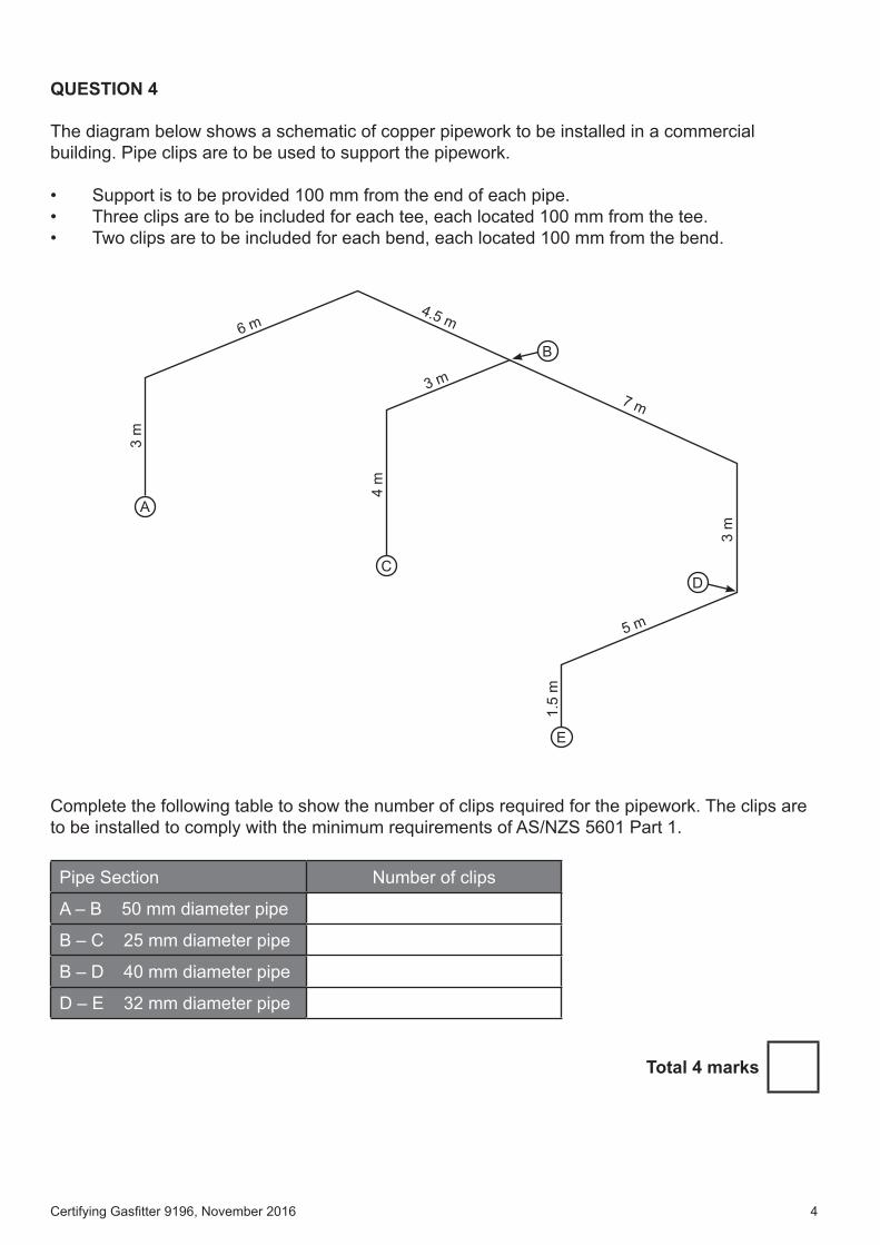
The diagram below shows a schematic of copper pipework to be installed in a commercial building. Pipe clips are to be used to support the pipework.
• Support is to be provided 100 mm from the end of each pipe.• Three clips are to be included for each tee, each located 100 mm from the tee.• Two clips are to be included for each bend, each located 100 mm from the bend.
E
A
C
B
D
3 m
4 m
3 m
1.5
m
5 m
7 m3 m
6 m4.5 m
Complete the following table to show the number of clips required for the pipework. The clips are to be installed to comply with the minimum requirements of AS/NZS 5601 Part 1.
Pipe Section Number of clips
A – B 50 mm diameter pipe
B – C 25 mm diameter pipe
B – D 40 mm diameter pipe
D – E 32 mm diameter pipe
Total 4 marks
Certifying Gasfitter 9196, November 2016 5
QUESTION 5
A plant room is fitted with mechanical supply ventilation and natural exhaust ventilation directly to outside. The plant room houses a 450 MJ induced draft boiler and two 30 MJ storage hot water cylinders with atmospheric burners.
(a) Determine in m3 the minimum volume of air per hour the ventilation system must be able to supply.
(5 marks)
(b) Suppose a natural high level exhaust opening is used.
Calculate the minimum size of the exhaust opening.
(2 marks)
(c) Suppose a mechanical high level exhaust is used.
Calculate in m3 the minimum volume of air the fan must be capable of moving per hour.
(1 mark)
(d) State the additional safety requirement that must be met, according to AS/NZS 5601, with regard to the operation of gas appliances with a mechanical ventilation system.
(2 marks)
Total 10 marks
Certifying Gasfitter 9196, November 2016 6
QUESTION 6
List FOUR aspects related to a gas installation that must be taken into account before suitability of a proprietary piping system can be confirmed as specified by AS/NZS 5601 Part 1.
1
2
3
4
Total 2 marks
Certifying Gasfitter 9196, November 2016 7
QUESTION 7
(a) A natural gas appliance has an efficiency of 80%. The test dial on the gas meter connected to this appliance completes 1 revolution in 1 minute
10 seconds. The test dial on the meter is marked 0.05 m3 per revolution. The heating value (HV) of natural gas is 40 MJ/m3.
Calculate, in kW, the energy output for the appliance. Formula: Gas rate in MJ/hr = m3 x HV x 3600 time taken in seconds
(5 marks)
(b) If the same meter used in (a) was measuring LPG, state how the amount of energy passed during 1 revolution of the test dial would change.
(1 mark)
Total 6 marks
Certifying Gasfitter 9196, November 2016 8
QUESTION 8
State FIVE factors that need to be specified when selecting a regulator for a gas installation.
1
2
3
4
5
Total 5 marks
Certifying Gasfitter 9196, November 2016 9
QUESTION 9
(a) List SIX items of information that must be permanently marked on every gas appliance.
1
2
3
4
5
6
(3 marks)
(b) A natural draft flue is being designed for a gas appliance.
State SIX factors to be taken into account when calculating the size of the flue.
1
2
3
4
5
6
(3 marks)
Total 6 marks
Certifying Gasfitter 9196, November 2016 10
QUESTION 10
The Gas (Safety and Measurement) Regulations define three categories of gasfitting work: low-risk gasfitting, general gasfitting and high-risk gasfitting.
(a) Give TWO examples of gasfitting that are classed as low-risk gasfitting.
1
2
(2 marks)
(b) Give TWO examples of gasfitting that are classed as high-risk gasfitting.
1
2
(2 marks)
(c) State what would be classed as general gasfitting.
(1 mark)
(d) Describe what is meant by the term ‘like for like’ in relation to the installation of gas appliances.
(1 mark)
Total 6 marks
Certifying Gasfitter 9196, November 2016 11
QUESTION 11
Where the potential of a fall exists on a work site, hazards need to be managed.
(a) State how the hazard of working at height can be eliminated.
(1 mark)
(b) Give FOUR examples of how the hazard of working at height can be minimised.
1
2
3
4
(4 marks)
Total 5 marks
Certifying Gasfitter 9196, November 2016 12
QUESTION 12
(a) State the organisation to which a Particular Hazardous Work Notification form needs to be submitted.
(1 mark)
(b) State how long before work commences a Particular Hazardous Work Notification form should be submitted.
(1 mark)
(c) Give FIVE items of information that are to be provided on a Particular Hazardous Work Notification form.
1
2
3
4
5
(5 marks)
Total 7 marks
Certifying Gasfitter 9196, November 2016 13
QUESTION 13
Use AS/NZS 5601 Part 1 to complete the table below to show the outlet operating pressure a consumer piping gas regulator is permitted to provide before a permanent and durable notice displaying the pressure is required.
Maximum outlet operating pressure LPG
Maximum outlet operating pressure natural gas
Total 2 marks
Certifying Gasfitter 9196, November 2016 14
QUESTION 14
A fault has developed on a gas oven. After the oven has been running for 20 minutes, it shuts the gas off and must be manually restarted.
Give THREE likely causes for this to occur.
1
2
3
Total 3 marks
Certifying Gasfitter 9196, November 2016 15
SECTION B
Answer the following multiple-choice questions by writing your answer (A, B, C, D or E) in the box provided after each one of the questions.
Each correct answer in this section of the examination is worth 1 mark.
Should your choice of answer be unclear no mark will be awarded.
1. According to AS/NZS 5601, when using uPVC for a flue, what temperature should the flue gases not be permitted to exceed?
A 60°C.
B 65°C.
C 75°C.
D 90°C.
E 100°C.
2. LPG cylinders need to be restrained against seismic activity if they are larger than what capacity?
A 8 litres.
B 12 litres.
C 18 litres.
D 20 litres.
E 25 litres.
3. How is the capacity of a sub-meter determined?
A One whole revolution of the test dial is the capacity of the meter.
B The test dial is used to check the volume of the meter.
C The capacity of the meter multiplied by the meter factor.
D The gas supplier must be contacted to ascertain meter volumes.
E The volume is indicated on the meter badge.
Certifying Gasfitter 9196, November 2016 16
4. Which of the following is not a flame failure system?
A Flame rectification.
B Mercury vapour valve.
C Oxygen depletion pilot.
D Ultra violet.
E Thermoelectric.
5. When a practising licence holder changes address, within what period must the Registrar be notified?
A 10 days.
B 15 days.
C 1 month.
D 3 months.
E 6 months.
6. According to AS/NZS 5601 Part 2, what is the minimum possible permitted free area of the total permanent ventilation for any space in a caravan that contains a gas appliance?
A 1000 mm2.
B 2000 mm2.
C 3000 mm2.
D 4000 mm2.
E 5000 mm2.
7. A 9 kg LPG cylinder is permitted to be used indoors with which type of connection?
A Companion/camping.
B QCC.
C POL.
D CGA555.
E Primus.
Certifying Gasfitter 9196, November 2016 17
8. When a gas appliance is to be installed in garage how high above the ground should the burners and combustion air intake be situated?
A 100 mm.
B 250 mm.
C 300 mm.
D 450 mm.
E 600 mm.
9. Other than a portable space heater, when is it permissible for a gas appliance fitted with wheels and a flexible hose to not be fitted with a device that will restrict the movement of the appliance?
A When the mass of the appliance is 20 kg or less.
B When it is installed in a commercial kitchen.
C When the mass of the appliance exceeds 30 kg.
D When the width of the appliance exceeds the height.
E When it is installed below an air extraction unit.
Total 9 marks
For Examiner’s use only
Question number
Marks
Marks
1
2
3
4
5
6
7
8
9
10
11
12
13
14
Section B
Total
Page 1 of 1
Composite Pipe System Sizing Guide
1. Using the information provided Identify and label which branch has the largest total Mega joule load.
2. Tabulate the length of the pipework from the end of the chosen branch back to the source of gas supply. This is the Main Run write this length in the sizing table.
3. Add all appliance mega‐joule ratings together to calculate the total load of the installation.
This is the Total Mj write this total in the sizing table.
4. Use the ‘Composite Pipe Correction Factor Chart’ from your resource to find the correct pipe sizes required for this installation as below.
Make sure you use the correct chart section for the installation
Find the total ‘Pipe Length’ (equal to or greater than) of the Main Run in the top row of the appropriate chart
Drop down that column until you find the number equal to or greater than Total Mj for the installation.
Move to the right hand side of the chart to find the ‘Additional Meters per Fitting’ for your installation. Write this Additional Meters per Fitting length in the sizing table.
Count the number of fittings on the Main Run of the installation identified in step 3. Include bends, junctions, and termination points (bracket elbows, hose plates, meter or cylinder connections etc). Write this Number of Fittings in the sizing table.
5. Multiply the Number of Fittings by the ‘Additional Meters per Fitting’ figure.
Add this value to the Main Run from step 3. This is the new Corrected Length of pipework. Write this Corrected Length in the sizing table.
6. Use this Corrected Length on the ‘Composite Pipe Correction Factor Chart’ again in the top row of the
appropriate chart.
Use the column in the chart below this ‘Corrected Length’ to find the Mj ratings for each pipe section of this installation.
This is now the only column required for sizing of all the pipe sections of your installation.
7. Complete the Pipe Section Table
Calculate the Mega Joules that each section of pipework conveys. In the selected column find the correct loading for the branch and follow the row to the left of the chart to find the corresponding pipe diameter.
Record all Mj loadings and pipe sizes in the Pipe Section Table to complete the exercise.