NON-CE & Frymaster, a member of the Commercial Food Equipment Service Association, recommends using CFESA Certified Technicians. PRINTED IN THE UNITED STATES 24-Hour Service Hotline 1-800-551- 8633 www.frymaster.com Email: [email protected]Series FMCF, FMCFE, FMCFEC, MJCF, MJCFE, MJCFEC, KJ3FC, JCFX, J3F & J65X. CF Series Gas Fryers Installation and Operation Manual *8195613* 03/2016
Transcript
NON-CE &
Frymaster, a member of the Commercial Food Equipment Service Association, recommends using CFESA Certified Technicians.
Series FMCF, FMCFE, FMCFEC, MJCF, MJCFE, MJCFEC, KJ3FC,
JCFX, J3F & J65X.
CF
Series G
as Fryers
Installation and Operation M
anual
*8195613* 03/2016
ii
NOTICE This appliance is intended for professional use only and is to be operated by qualified personnel only. A Frymaster/DEAN Factory Authorized Servicer (FAS) or other qualified professional should perform installation, maintenance, and repairs. Installation, maintenance, or repairs by unqualified personnel may void the manufacturer’s warranty. See Chapter 1 of this manual for definitions of qualified personnel.
NOTICE This equipment must be installed in accordance with the appropriate national and local codes of the country and/or region in which the appliance is installed. See NATIONAL CODE REQUIREMENTS in Chapter 2 of this manual for specifics.
NOTICE TO U.S. CUSTOMERS This equipment is to be installed in compliance with the basic plumbing code of the Building Officials and Code Administrators International, Inc. (BOCA) and the Food Service Sanitation Manual of the U.S. Food and Drug Administration.
NOTICE Drawings and photos used in this manual are intended to illustrate operational, cleaning and technical procedures and may not conform to onsite management operational procedures.
NOTICE TO OWNERS OF UNITS EQUIPPED WITH COMPUTERS
U.S.
This device complies with Part 15 of the FCC rules. Operation is subject to the following two conditions: 1) This device may not cause harmful interference, and 2) This device must accept any interference received, including interference that may cause undesired operation. While this device is a verified Class A device, it has been shown to meet the Class B limits.
CANADA
This digital apparatus does not exceed the Class A or B limits for radio noise emissions as set out by the ICES-003 standard of the Canadian Department of Communications.
Cet appareil numerique n’emet pas de bruits radioelectriques depassany les limites de classe A et B prescrites dans la norme NMB-003 edictee par le Ministre des Communcations du Canada.
DANGER Improper installation, adjustment, maintenance or service, and unauthorized alterations or modifications can cause property damage, injury, or death. Read the installation, operating, and service instructions thoroughly before installing or servicing this equipment. Only qualified service personnel may convert this appliance to use a gas other than that for which it was originally configured.
DANGER No structural material on the fryer should be altered or removed to accommodate placement of the fryer under a hood. Questions? Call the Frymaster/Dean Service Hotline at 1-800-551-8633.
iii
DANGER Adequate means must be provided to limit the movement of this appliance without depending upon the gas line connection. Single fryers equipped with legs must be stabilized by installing anchor straps. All fryers equipped with casters must be stabilized by installing restraining chains. If a flexible gas line is used, an additional restraining cable must be connected at all times when the fryer is in use.
DANGER The front ledge of the fryer is not a step! Do not stand on the fryer. Serious injury can result from slips or contact with the hot oil.
DANGER Do not store or use gasoline or other flammable liquids or vapors in the vicinity of this or any other appliance.
DANGER Instructions to be followed in the event the operator smells gas or otherwise detects a gas leak must be posted in a prominent location. This information can be obtained from the local gas company or gas supplier.
DANGER The crumb tray in fryers equipped with a filter system must be emptied into a fireproof container at the end of frying operations each day. Some food particles can spontaneously combust if left soaking in certain shortening material.
WARNING Do not bang fry baskets or other utensils on the fryer’s joiner strip. The strip is present to seal the joint between the fry vessels. Banging fry baskets on the strip to dislodge shortening will distort the strip, adversely affecting its fit. It is designed for a tight fit and should only be removed for cleaning.
NOTICE IF, DURING THE WARRANTY PERIOD, THE CUSTOMER USES A PART FOR THIS MANITOWOC EQUIPMENT OTHER THAN AN UNMODIFIED NEW OR RECYCLED PART PURCHASED DIRECTLY FROM FRYMASTER/DEAN, OR ANY OF ITS AUTHORIZED SERVICE CENTERS, AND/OR THE PART BEING USED IS MODIFIED FROM ITS ORIGINAL CONFIGURATION, THIS WARRANTY WILL BE VOID. FURTHER, FRYMASTER/DEAN AND ITS AFFILIATES WILL NOT BE LIABLE FOR ANY CLAIMS, DAMAGES OR EXPENSES INCURRED BY THE CUSTOMER WHICH ARISE DIRECTLY OR INDIRECTLY, IN WHOLE OR IN PART, DUE TO THE INSTALLATION OF ANY MODIFIED PART AND/OR PART RECEIVED FROM AN UNAUTHORIZED SERVICE CENTER.
NOTICE The Commonwealth of Massachusetts requires any and all gas products to be installed by a licensed plumber or pipe fitter.
WARNING This appliance is not intended for use by children under the age of 16 or persons with reduced physical, sensory or mental capabilities, or lack of experience and knowledge, unless they have been given supervision concerning use of the appliance by a person responsible for their safety. Do not allow children to play with this appliance.
iv
CF Series Gas Fryers
TABLE OF CONTENTS
PAGE # CHAPTER 1: General Information
1.1 Applicability and Validity .............................................................................................................. 1-1 1.2 Parts Ordering and Service Information ......................................................................................... 1-1 1.3 Safety Information .......................................................................................................................... 1-2 1.4 European Community (CE) Specific Information .......................................................................... 1-2 1.5 Equipment Description ................................................................................................................... 1-3 1.6 Installation, Operating, and Service Personnel ............................................................................... 1-4 1.7 Definitions ...................................................................................................................................... 1-4 1.8 Shipping Damage Claim Procedure ............................................................................................... 1-5
CHAPTER 2: Installation Instructions
2.1 General Installation Requirements ................................................................................................. 2-1 2.2 Dimensions ..................................................................................................................................... 2-4 2.3 Caster/Leg Installation .................................................................................................................... 2-4 2.4 Pre-Connection Preparations .......................................................................................................... 2-5 2.5 Connection to Gas Line .................................................................................................................. 2-6 2.6 Converting to Another Gas Type .................................................................................................... 2-9
CHAPTER 3: Operating Instructions
3.1 Start-Up Procedure ......................................................................................................................... 3-1 3.2 Boiling-Out the Frypot ................................................................................................................... 3-4 3.3 Shutting the Fryer Down ................................................................................................................ 3-5 3.4 Controller Operation and Programming ......................................................................................... 3-5
CHAPTER 4: Filtration Instructions
4.1 Draining and Manual Filtering ....................................................................................................... 4-1 4.2 Filter Magic II Filtration System Operation ................................................................................... 4-3 Preparing the Filter Unit for Use and/or Changing Filter Paper ..................................................... 4-3 Operation of the Filter Unit ............................................................................................................ 4-6
CHAPTER 5: Preventive Maintenance
5.1 Fryer Preventive Maintenance Checks and Services ...................................................................... 5-1 Daily Checks and Services ............................................................................................................. 5-1 Weekly Checks and Services .......................................................................................................... 5-2 Quarterly Checks and Services ....................................................................................................... 5-2 Semi-Annual Checks and Services ................................................................................................. 5-5 5.2 Filter Magic II Filtration System Preventive Maintenance Checks and Services .......................... 5-5 5.3 Annual/Periodic System Inspection ................................................................................................ 5-6
CHAPTER 6: Operator Troubleshooting
6.1 Introduction .................................................................................................................................... 6-1 6.2 Troubleshooting Fryers with Solid State (Analog), Digital, or CM III.5 Controllers .................... 6-2 6.3 Troubleshooting Fryers with Thermostat Controls ......................................................................... 6-3 6.4 Troubleshooting the Built-In Filtration System .............................................................................. 6-4 6.5 Troubleshooting Abnormal Burner Operation................................................................................ 6-6
CF SERIES GAS FRYERS CHAPTER 1: INTRODUCTION
1-1
1.1 Applicability and Validity The CF Series Gas Fryer model family has been approved by the European Union for sale and installation in the following EU countries: AT, BE, DE, DK, ES, FI, FR, GB, IE, IT, LU, NL, NO, PT and SE. This manual is applicable to and valid for all CF Series Gas Fryer units sold in English-speaking countries, including those in the European Union. Where conflicts exist between instructions and information in this manual and local or national codes of the country in which the equipment is installed, installation and operation shall comply with those codes. This appliance is only for professional use and shall be used by qualified personnel only, as defined in Section 1.7. 1.2 Parts Ordering and Service Information In order to assist you as quickly as possible, the Factory Authorized Servicer (FAS) or Service Department representative requires certain information about your equipment. Most of this information is printed on a data plate affixed to the inside of the fryer door. Parts orders must be placed directly with your local FAS or distributor. Your nearest Frymaster FAS is accessible at www.frymaster.com or you can contact the Frymaster Service Department at 1-800-24-FRYER or 1-318-865-1711. When ordering parts, the following information is required:
Model Number: Serial Number: Type of Gas or Voltage: Item Part Number: Quantity Needed:
Service information may be obtained by contacting your local FAS. Information may also be obtained by calling the Frymaster Technical Service Department at 1-800-551-8633 or 1-318-865-1711. When requesting service, please have the following information ready:
Model Number: Serial Number: Type of Gas:
CF SERIES GAS FRYERS
CHAPTER 1: INTRODUCTION
1-2
In addition to the model number, serial number, and type of gas, please be prepared to describe the nature of the problem and have ready any other information that you think may be helpful in solving your problem. 1.3 Safety Information Before attempting to operate your unit, read the instructions in this manual thoroughly. Your fryer is equipped with two automatic safety features:
High temperature detection shuts off gas to the burner assembly should the controlling thermostat fail.
A safety switch built into the drain valve of units with built-in filtration systems prevents burner ignition with the drain valve even partially open.
Throughout this manual, you will find notations enclosed in double-bordered boxes similar to the ones below.
CAUTION CAUTION boxes contain information about actions or conditions that may cause or result in a malfunction of your system.
WARNING WARNING boxes contain information about actions or conditions that may cause or result in damage to your system, and which may cause your system to malfunction.
DANGER DANGER boxes contain information about actions or conditions that may cause or result in injury to personnel, and which may cause damage to your system and/or cause your system to malfunction.
1.4 European Community (CE) Specific Information The European Community (CE) has established certain specific standards regarding equipment of this type. Whenever there is a difference between CE and non-CE standards, the information or instructions concerned are identified in tables.
CF SERIES GAS FRYERS
CHAPTER 1: INTRODUCTION
1-3
1.5 Equipment Description CF Series gas fryers are specifically designed for high volume frying, especially fish, chicken and other breaded products. Models in this series include FMCF, FMCFE, FMCFEC, MJCF, MJCFE, MJCFEC, KJ3FC and J65X variants. (The J65X variant is a drop-in unit without cabinetry.) Fryers in this series may be equipped with built-in Filter Magic filtration systems (FMCF variants), or may be configured for manual filtration (MJCF variants). All models may be configured for electrical power supplies ranging from 120 to 240 VAC. FMCF, MJCF AND J65X models utilize a combination gas valve to control the burner, but do not require an external AC power source. An AC power source is required for these models when equipped with built-in filtration systems. FMCFE, KJ3FC and MJCFE models utilize a combination gas valve to control the burner and require an external AC power source. The electrical power supply to the gas valve is controlled by a manually-operated thermostat controller or a computer/controller. The FMCFEC and MJCFEC models are equipped with Computer Magic III.5 computers. The KJ3FC variants are equipped with user-supplied or KFC-1 computers. All models are of an open-pot design with no tubes and have a hand-sized opening into the deep cold zone, which makes cleaning the stainless frypot quick and easy. Fryers equipped with built-in filtration systems are shipped completely assembled. Fryers without built-in filtration require installation of legs or optional casters at point of use. All fryers are shipped with a package of standard accessories. Each fryer is adjusted, tested, and inspected at the factory before crating for shipment. Frypots are constructed of welded, heavy- gauge stainless steel. Heating is supplied by a burner assembly having multiple gas jets, which are focused on ceramic targets located around the lower side of the frypot. The burner assembly can be configured for natural gas, propane, or manufactured gas, as required by the customer. A drain is tapped into the center of the frypot, with a front-controlled manual ball valve. Each fryer is equipped with a thermostat probe for precise temperature control. The probe is located on the centerline of the frypot for rapid response to changes in loads and to provide the most accurate temperature measurement. CF Series fryers may be equipped with an optional melt cycle feature, which pulses the burner on and off at a controlled rate. The melt cycle feature is designed to prevent scorching and uneven heating of the frypot for customers who use solid shortening. The controls on your fryer vary depending on the model and configuration purchased. Control options include thermostat controls, solid state (analog) controllers, digital controllers, KFC-1, Fastron or Computer Magic III.5 computers. Each type is covered in a separate manual provided with your equipment.
CF SERIES GAS FRYERS
CHAPTER 1: INTRODUCTION
1-4
1.6 Installation, Operating, and Service Personnel Operating information for Frymaster equipment has been prepared for use by qualified and/or authorized personnel only, as defined in Section 1.7. All installation and service on Frymaster equipment must be performed by qualified, certified, licensed, and or/authorized installation or service personnel, as defined in Section 1.7. 1.7 Definitions QUALIFIED AND/OR AUTHORIZED OPERATING PERSONNEL
Qualified/authorized operating personnel are those who have carefully read the information in this manual and have familiarized themselves with the equipment functions, or who have had previous experience with the operation of the equipment covered in this manual.
QUALIFIED INSTALLATION PERSONNEL Qualified installation personnel are individuals, or firms, corporations, or companies which, either in person or through a representative, are engaged in and are responsible for the installation of gas-fired appliances. Qualified personnel must be experienced in such work, be familiar with all gas precautions involved, and have complied with all requirements of applicable national and local codes. QUALIFIED SERVICE PERSONNEL Qualified service personnel are those that are familiar with Frymaster equipment and who have been authorized by Frymaster, L.L.C. to perform service on Frymaster equipment. All authorized service personnel are required to be equipped with a complete set of service and parts manuals, and to stock a prescribed minimum amount of Frymaster equipment parts. Your nearest Frymaster FAS is accessible at www.frymaster.com or you can contact the Frymaster Service Department at 1-800-24-FRYER or 1-318-865-1711. Failure to use qualified service personnel will void the Frymaster Warranty on your equipment.
CF SERIES GAS FRYERS
CHAPTER 1: INTRODUCTION
1-5
1.8 Shipping Damage Claim Procedure Your Frymaster equipment was carefully inspected and packed before leaving the factory. The transportation company assumes full responsibility for safe delivery upon acceptance of the equipment for transport. What to do if your equipment arrives damaged: 1. File a claim for damages immediately, regardless of the extent of damages.
2. Inspect for and record all visible loss or damage, and ensure that this information is noted on the freight bill or express receipt and is signed by the person making the delivery.
3. Concealed loss or damage that was unnoticed until the equipment was unpacked should be recorded and reported to the freight company or carrier immediately upon discovery. A concealed damage claim must be submitted within 15 days of the date of delivery. Ensure that the shipping container is retained for inspection.
FRYMASTER L.L.C. DOES NOT ASSUME RESPONSIBILITY FOR DAMAGE OR
LOSS INCURRED IN TRANSIT.
RETAIN AND STORE THIS MANUAL IN A SAFE PLACE FOR FUTURE USE.
CF SERIES GAS FRYERS CHAPTER 2: INSTALLATION INSTRUCTIONS
2-1
2.1 General Installation Requirements Qualified, licensed, and/or authorized installation or service personnel, as defined in Section 1.7 of this manual, should perform all installation and service on Frymaster equipment. Conversion of this appliance from one type of gas to another should only be performed by qualified, licensed, and/or authorized installation or service personnel as defined in Section 1.7 of this manual. Failure to use qualified, licensed, and/or authorized installation or service personnel (as defined in Section 1.7 of this manual) to install, convert to another gas type or otherwise service this equipment will void the Frymaster warranty and may result in damage to the equipment or injury to personnel. Where conflicts exist between instructions and information in this manual and local or national codes or regulations, installation and operation shall comply with the codes or regulations in force in the country in which the equipment is installed.
DANGER Building codes prohibit a fryer with its open tank of hot oil being installed beside an
open flame of any type, including those of broilers and ranges.
Upon arrival, inspect the fryer carefully for visible or concealed damage. (See Shipping Damage Claim Procedure in Chapter 1.) If there is no damage, remove the fryer from the pallet. Discard the box.
DANGER Frymaster appliances equipped with legs are for stationary installations. Appliances
fitted with legs must be lifted during movement to avoid damage to the appliance and bodily injury. For movable installations, optional equipment casters must be
used. Questions? Call 1-800-551-8633.
PROPER INSTALLATION IS ESSENTIAL FOR EFFICIENT, TROUBLE-FREE OPERATION OF YOUR FRYER. ANY UNAUTHORIZED ALTERATIONS MADE TO THIS EQUIPMENT WILL VOID THE FRYMASTER WARRANTY. Upon arrival, inspect the fryer carefully for visible or concealed damage. (See Shipping Damage Claim Procedure in Chapter 1.)
CF SERIES GAS FRYERS
CHAPTER 2: INSTALLATION INSTRUCTIONS
2-2
CLEARANCE AND VENTILATION
DANGER No structural material on the fryer should be altered or removed to accommodate
placement of the fryer under a hood. Questions? Call the Frymaster/Dean Service Hotline at 1-800-551-8633.
DANGER This appliance must be installed with sufficient ventilation to prevent the occurrence of unacceptable concentrations of substances harmful to the health of personnel in
the room in which it is installed.
The fryer(s) must be installed with a 6" (150 mm) clearance at both sides and back when installed adjacent to combustible construction; no clearance is required when installed adjacent to noncombustible construction. If a flue deflector is included with the fryer, ensure that the flue deflector is installed as per the instruction sheet provided. It is recommended that a flue deflector is used for fryers installed near a wall cavity that contains combustible materials. A minimum of 24" (600 mm) clearance should be provided at the front of the fryer. One of the most important considerations of efficient fryer operation is ventilation. Ensure the fryer is installed so that products of combustion are removed efficiently, and that the kitchen ventilation system does not produce drafts that interfere with proper burner operation. The fryer flue opening must not be placed close to the intake of the exhaust fan, and the fryer must never have its flue extended in a "chimney" fashion. An extended flue will change the combustion characteristics of the fryer, causing longer recovery time. It also frequently causes delayed ignition. To provide the airflow necessary for good combustion and burner operation, the areas surrounding the fryer front, sides, and rear must be kept clear and unobstructed. Fryers must be installed in an area with an adequate air supply and adequate ventilation. Adequate distances must be maintained from the flue outlet of the fryer to the lower edge of the ventilation filter bank. Filters should be installed at an angle of 45 degrees. Place a drip tray beneath the lowest edge of the filter. For U.S. installation, NFPA standard No. 96 states, "A minimum distance of 18 in. (450 mm) should be maintained between the flue outlet and the lower edge of the grease filter. " Frymaster recommends that the minimum distance be 24 in. (600 mm) from the flue outlet to the bottom edge of the filter when the appliance consumes more than 120,000 BTU per hour. Information on construction and installation of ventilating hoods can be found in the NFPA standard cited above. A copy of the standard may be obtained from the National Fire Protection Association, Battery March Park, Quincy, MA 02269.
CF SERIES GAS FRYERS
CHAPTER 2: INSTALLATION INSTRUCTIONS
2-3
NATIONAL CODE REQUIREMENTS
The type of gas for which the fryer is equipped is stamped on the data plate attached to the inside of the fryer door. Connect a fryer stamped "NAT" only to natural gas, those stamped "PRO" only to propane gas, and those stamped "MFG" only to manufactured gas.
Installation shall be made with a gas connector that complies with national and local codes, and, where applicable, CE codes. Quick-Disconnect devices, if used, shall likewise comply with national, local, and, if applicable, CE codes. AUSTRALIAN REQUIREMENTS
To be installed in accordance with AS 5601, local authority, gas, electricity, and any other relevant statutory regulations ELECTRICAL GROUNDING REQUIREMENTS
All electrically operated appliances must be grounded in accordance with all applicable national and local codes, and, where applicable, CE codes. A wiring diagram is located on the inside of the fryer door. Refer to the rating plate on the inside of the fryer door for proper voltages.
DANGER If this appliance is equipped with a three-prong (grounding) plug for your protection against electrical shock, it must be plugged directly into a properly grounded three-prong receptacle. Do not cut, remove, or otherwise bypass the grounding prong on
this plug!
DANGER This equipment requires electrical power for operation. Place the gas control valve in the OFF position in case of a prolonged power outage. Do not attempt to use the
equipment during a power outage.
FCC COMPLIANCE
The user is cautioned that any changes or modifications to Frymaster computers not expressly approved by the party responsible for compliance could void the user’s authority to operate the equipment. Frymaster computers have been tested and found to comply with the limits for a Class A digital device, pursuant to Part 15 of the FCC rules. While these devices are verified as Class A devices, they have been shown to meet the Class B limits. These limits are designed to provide reasonable protection against harmful interference when the equipment is operated in a commercial environment. This equipment generates, uses, and can radiate radio frequency energy and, if not installed and used in accordance with the instruction manual, may cause harmful interference to radio communications. Operation of the equipment in a residential area is likely to cause harmful interference in which case the user will be required to correct the interference at the user’s expense.
CF SERIES GAS FRYERS
CHAPTER 2: INSTALLATION INSTRUCTIONS
2-4
If necessary, the user should consult the dealer or an experienced radio and television technician for additional suggestions.
The user may find the booklet "How to Identify and Resolve Radio-TV Interference Problems" helpful. It is prepared by the Federal Communications Commission and is available from the U.S. Government Printing Office, Washington, DC 20402, Stock No. 004-000-00345-4. 2.2 Dimensions
2.3 Caster/Leg Installation
DANGER DO NOT install this appliance without legs or casters.
36.48 [927]
SIDE VIEW FRYER FRONT VIEW
5.50 [140]
TOP VIEW
18.18 [462] 3/4" NPT GAS CONNECTION
8.28 [210]
3/4" NPT GAS CONNECTION
DIMENSIONS INCHES[MM]
CENTEROF DRAINTUBE
46.15 [1172]
47.80 [1214]
13.63 [346]
20.83 [529]
CORDSET
CORDSET
39.86 [1013]
CF SERIES GAS FRYERS
CHAPTER 2: INSTALLATION INSTRUCTIONS
2-5
Depending upon the specific configuration ordered, the fryer might have been shipped without installed casters or legs. If casters or legs are installed, you may skip this section and proceed to Section 2.3, Pre-Connection Preparations.
If your fryer requires the installation of casters/legs, install them in accordance with the instructions included in your accessory package. 2.4 Pre-Connection Preparations
DANGER Do not connect this appliance to the gas supply before completing each step in this
section. After the fryer has been positioned under the fry station exhaust hood, ensure the following has been accomplished: 1. Adequate means must be provided to limit the movement of fryers without depending upon the
gas line connections. If a flexible gas hose is used, a restraining cable must be connected at all times when the fryer is in use. The restraining cable and installation instructions are packed with the flexible hose in the accessories box that was shipped with your unit.
2. Single unit fryers must be stabilized by installing restraining chains on fryers equipped with
casters or anchor straps on fryers equipped with legs. Follow the instructions shipped with the casters/legs to properly install the chains or straps.
DANGER Do not attach an apron drain board to a single fryer. The fryer may become
unstable, tip over, and cause injury. The appliance area must be kept free and clear of combustible materials at all times.
3. Level fryers equipped with legs by screwing out the legs approximately 1 inch, and then adjust
them so that the fryer is level and at the proper height in the exhaust hood. Frymaster recommends that the minimum distance from the flue outlet to the bottom edge of the filter be 24 inches (600 mm) when the appliance consumes more than 120,000 BTU per hour.
For fryers equipped with casters, there are no built-in leveling devices. The floor where the fryer
is to be installed must be level. 4. Test the fryer electrical system: Verify correct voltage and connect per National codes and
regulations. a. Plug the fryer electrical cord(s) into a grounded electrical receptacle.
b. Place the power switch in the ON position.
CF SERIES GAS FRYERS
CHAPTER 2: INSTALLATION INSTRUCTIONS
2-6
For fryers equipped with thermostat controls, verify that the power and heat lights are lit.
For fryers having computer or digital displays, verify that the display indicates
c. Place the fryer power switch in the OFF position. Verify that the power and heat lights are out, or that the display is blank.
5. Refer to the data plate on the inside of the fryer door to verify that the fryer burner is configured
for the proper type of gas before connecting the gas line quick-disconnect device or piping from the gas supply line.
6. Verify the minimum and maximum gas supply pressures for the type of gas to be used in
accordance with the accompanying tables: 7. For fryers equipped with a built-in filter system and/or basket lifts, plug the electrical cord(s) into
a power receptacle behind the fryer. 2.5 Connection to Gas Line
DANGER
CE Standard for Incoming Gas Pressure
Model CF
Gas Type G20 G25 G31
Pressure (mbar) 20 20‐25 37‐50
Orifice Size (mm) 1.40 1.40 0.86
Number of Orifices 18 18 18
Manifold Pressure (mbar) 7,5 10 20,6
Non‐ CE Standard for Incoming Gas Pressure
Model CF
Gas Type Nat LP
Min Pressure W.C/kpa/mbar 6/1.49/14.93 11/2.74/27.37
Max Pressure W.C/kpa/mbar 14/3.48/34.84 14/3.48/34.84
Orifice Size (mm) 1.45 0.86
Number of Orifices 18 18
Manifold Pressure (WC) 3.5 8.25
Australian Standard for Incoming Gas Pressure
Model CF
Gas Type Nat LP
Min Pressure 1.13 kpa 2.7 kpa
Max Pressure 5.0 kpa 7.0 kpa
Orifice Size (mm) 1.4 0.90
Number of Orifices 18 18
Manifold Pressure 0.90 kpa 2.30 kpa
Gas Consumption (per hour)
158.2Mj 158.2Mj
NOTE: Gas specifications are included on appliance data plate located inside the door.
Korea Standard for Incoming Gas Pressure
Model CF
Gas Type LNG (Natural) LPG (Propane)
Min Pressure W.C/kpa/mbar 4/1.00/10.00 9.2/2.30/23.00
Max Pressure W.C/kpa/mbar 10/2.50/25.00 13.2/3.30/33.00
Orifice Size (mm) 1.40 0.90
Number of Orifices 18 18
Manifold Pressure (WC) 3.5 8.25
CF SERIES GAS FRYERS
CHAPTER 2: INSTALLATION INSTRUCTIONS
2-7
Before connecting new pipe to this appliance, the pipe must be blown out thoroughly to remove all foreign material. Foreign material in the burner and gas
controls will cause improper and dangerous operation.
DANGER When pressure-testing incoming gas supply lines, disconnect the fryer from the gas
line if the test pressure will be ½ PSIG (3.45 kPa, 13.84 inches W.C.) or greater to avoid damage to the fryer’s gas tubes and gas valve(s).
The CF Series fryer has received the CE mark for the countries and gas categories indicated in the table below.
BEI2E+(S)
I3PG20/G25
G3120/25
37
DEI2 ELL13P
G20/G25G31
2050
FR II2Esi3PG20/G25
G3120/25
37 ET 50
LU I2E G20/G25 20/25
ES II2H3PG20G31
2037 ET 50
NL II2L3PG25G31
2550
IE-PT-GB II2H3PG20G31
2037
CE Approved Gas Categories
Country Category GasPressure
(mbar)
DK-GR-IT I2 H G20 20
The size of the gas line used for installation is very important. If the line is too small, the gas pressure at the burner manifold will be low. This may cause slow recovery and delayed ignition. The incoming gas supply line should be a minimum of 1½" (38 mm) in diameter. Refer to the chart on the following page for the minimum sizes of connection piping.
CF SERIES GAS FRYERS
CHAPTER 2: INSTALLATION INSTRUCTIONS
2-8
Gas Connection Pipe Sizes[Minimum incoming pipe size should be 1-1/2" (38 mm)]
* For distances of more than 20 feet (6 m) and/or more than four fittings or elbows, increase the connection by one pipe size.
CE Standard CE regulations require a combustion air supply of 2m3/h per kW per fryer. (See rating plate affixed to door for kW rating.)
1. Connect the quick-disconnect hose to the fryer quick-disconnect fitting under the fryer and to the
building gas line. The gas inlet connection will be up to 1.5” NPT (38.1mm), depending on the number of fryers in the battery. The gas connection point will be about 8” (200mm) from the floor. The left-to-right position will vary according to the number of fryers in the battery. NOTE: Some fryers are configured for a rigid connection to the gas supply line. These units are connected to the gas supply line at the rear of the unit.
When using thread compound, use very small amounts on male threads only. Use a pipe thread compound that is not affected by the chemical action of LP gases (Loctite PST567 sealant is one such compound). DO NOT apply compound to the first two threads. Applying compound to the first two threads will cause clogging of the burner orifices and control valve.
2. Open the gas-supply valve to the fryer and check all piping, fittings, and gas connections for leaks. A soap and water solution should be used for this purpose.
DANGER All connections must be sealed with a joint compound suitable for the gas being used and all connections must be tested with a solution of soapy water before
lighting any pilots.
Never use matches, candles, or any other ignition source to check for leaks. If gas odors are detected, shut off the gas supply to the appliance at the main shut-off valve and immediately contact the local gas company or an authorized service
agency for service.
CF SERIES GAS FRYERS
CHAPTER 2: INSTALLATION INSTRUCTIONS
2-9
3. Close the fryer drain valve and fill the frypot with water and boil-out solution to the bottom OIL-LEVEL line at the rear of the frypot. Light the fryer and perform the boil-out procedures that are described in the "Lighting Instructions" and "Boiling Out the Frypot" topics found in Chapter 3 of this manual. (non-KFC co-branded locations only)
DANGER "Dry-firing" your unit will cause damage to the frypot and can cause a fire. Always
ensure that melted shortening, cooking oil, or water is in the frypot before firing your unit. (In KFC co-branded locations, oil MUST be used rather than water.)
4. The burner manifold pressure should be checked at this time by the local gas company or an
authorized service agent. The tables on page 2-5 indicate the proper burner manifold pressures. 5. Check the thermostat calibration or temperature programmed into the computer.
For units equipped with thermostat controls, refer to the Thermostat Calibration instructions in Chapter 5.
For units equipped with other types of controllers, refer to the appropriate section of the separate Frymaster Fryer Controllers User’s Manual provided with your equipment for instructions on programming and operating your controller.
2.6 Ensure Burner Targets Are Properly Spaced The top edge of the metal burner target should be ¾” (13mm) from the frypot side. Bend the target bracket forward or back as necessary to get a uniform spacing. 2.7 Converting to Another Gas Type Your fryer is configured at the factory for either natural gas or Propane (LP) gas. If you desire to switch from one type of gas to another, a gas conversion kit must be installed by a Factory Authorized Service Center technician.
¾” (13mm) spacing between top edge of target and frypot.
CF SERIES GAS FRYERS
CHAPTER 2: INSTALLATION INSTRUCTIONS
2-10
DANGER This appliance was configured at the factory for a specific type of gas. Converting from one type of gas to another requires the installation of specific gas-conversion
components.
DANGER Switching to a different type of gas without installing the proper conversion kit may result in fire or explosion! NEVER ATTACH THIS APPLIANCE TO A GAS SUPPLY
FOR WHICH IT IS NOT CONFIGURED!
Conversion of this appliance from one type of gas to another should only be performed by qualified, licensed, and authorized installation or service personnel, as
defined in Section 1.7 of this manual.
Non-CE Gas Conversion Instructions
Call Frymaster Service (1-800-551-8633) to determine the conversion kit appropriate for your configuration and altitude. Contact your local FASC to order the kit and arrange for installation.
CE Gas Conversion Instructions
1. Between G20- and G25-type Natural Gas, adjust the gas pressure at the regulator. (Refer to the CE Standard Burner Manifold Gas Pressure Chart.) Do not change the orifice or pilot.
2. Between a 2nd family gas (G20 or G25) and a 3rd family gas (G31 Propane): a. Change the orifices. b. Change the pilot. c. Change the gas valve regulator. d. Adjust the manifold pressure. 3. Affix the new label included with the conversion kit next to the rating plate stating that the gas
type has been converted. Remove any references to the previously gas from the existing rating plate.
4. If the destination language changes, replace the labels. Call your local service agency of kitchen
equipment supplier for a label kit. The language of reference will be on the corner of the label. The following gas-conversion components and kits are available from your FASC:
CE Only: Propane (G31) to Natural (G20/G25)
Regulator only: P/N 810-1292 Pilot, regulator, and orifices kit: P/N 826-1478 Natural (G20/G25) to Propane (G31)
CF SERIES GAS FRYERS CHAPTER 3: OPERATING INSTRUCTIONS
3-1
3.1 Start-Up Procedure
DANGER Never operate this appliance with an empty frypot. The frypot must be filled with
water (non-KFC co-branded locations) or cooking oil/shortening before lighting the burners. Failure to do so will damage the frypot and may cause a fire.
WARNING The on-site supervisor is responsible for ensuring that operators are made aware of the inherent hazards of operating a hot oil filtering system, particularly the aspects
of oil filtration, draining and cleaning procedures.
CAUTION The cooking oil/shortening capacity of the CF Series fryer is 80 pounds (43 liters) at
70°F (21°C).
Before lighting the fryer, make sure the fryer is OFF and the frypot drain valve is closed. Remove the basket support rack, if installed, and fill the frypot to the bottom
OIL-LEVEL line.
If solid shortening is being used, make sure it is tightly packed down into the bottom of the frypot.
Non-CE Gas Valve Units configured for use in Non-CE countries are equipped with Non-CE Honeywell valves.
CE Gas Valve Units configured for use in CE countries are equipped with CE Honeywell valves.
CF SERIES GAS FRYERS
CHAPTER 3: OPERATING INSTRUCTIONS
3-2
ACCESSING THE PILOT The pilot is mounted on the left side of the burner manifold and is accessed through an opening in the front frypot insulation. Swing the round cover open and insert a long match or taper through the hole (see photo) when lighting the pilot.
LIGHTING THE PILOT ON NON-CE FRYERS
1. Ensure power to the unit is OFF, and then turn the gas valve knob to the OFF position. Wait at least 5 minutes, and then rotate the gas valve knob to the PILOT position (see Figure 1).
Lighting the Pilot
OF
FON
PILOT
OF
FON
PILOT
Figure 1 Figure 2
2. Push the knob in and light the pilot. (If the fryer is equipped with a piezo ignitor, repeatedly press the piezo ignitor button while depressing the gas valve knob until the pilot lights.) Continue to hold the knob in for about 60 seconds after the flame appears on the pilot. Release the knob. The pilot should remain lit.
CAUTION If the pilot fails to remain lit, turn the gas valve knob to the OFF position and wait at
least five minutes before attempting to re-light.
3. With the pilot lit, push down and slowly turn the knob to the ON position (Figure 2).
Insert match or taper through this hole to light pilot.
CF SERIES GAS FRYERS
CHAPTER 3: OPERATING INSTRUCTIONS
3-3
LIGHTING THE PILOT ON FRYERS WITH CE HONEYWELL GAS VALVES 1. Ensure power to the unit is OFF, and then press the OFF (red) button. Wait 5 minutes.
2. Place a flame near the pilot assembly, push and hold the PILOT (white) button in, light the pilot, and continue to depress the button for at least 60 seconds after the pilot lights. Failure to hold the button in long enough will cause the pilot to go out when the button is released. If the pilot goes out when the button is released, wait at least 5 minutes then repeat this step.
PLACING THE FRYER INTO OPERATION
CAUTION If this is the first time the fryer is being used after installation, refer to Section 3.2,
Boiling-Out the Frypot. (non-KFC co-branded locations)
For units equipped with Thermostat Controls (non-KFC co-branded locations) Place the Melt Cycle switch (if so equipped) to the ON position. Set the thermostat knob to the desired cooking temperature. The U-shaped burner should "light-off" and burn with a strong, blue flame.
CAUTION Thermostat-controlled fryers equipped with Melt Cycle switches will stay in the Melt
Cycle mode until the Melt Cycle switch is placed in the OFF position.
OFF Button PILOT Button
CF SERIES GAS FRYERS
CHAPTER 3: OPERATING INSTRUCTIONS
3-4
For units equipped with other than Thermostat Controls (non-KFC co-branded locations) Place the computer/controller ON/OFF switch in the ON position and set the controller to – or program the computer for – the desired cooking temperature, referred to as the setpoint. The U-shaped burner should light and burn with a strong, blue flame. The unit automatically enters the melt cycle mode if the frypot temperature is below 180°F (82°C). (NOTE: During the melt cycle, the burner will repeatedly fire for a few seconds, then go out for a longer period.) When the frypot temperature reaches 180°F (82°C), the unit will automatically switch to the heating mode. The burner will remain lit until the frypot temperature reaches the programmed cooking temperature (setpoint).
NOTE: In KFC co-branded locations, boil-out is NOT ALLOWED. Use the KFC
approved procedure. 3.2 Boiling-Out the Frypot To ensure that the frypot is free of any contamination resulting from its manufacture, shipping, and handling during installation, the frypot must be boiled out before first use. Frymaster recommends boiling out the frypot each time the oil or shortening is changed. Boil-out is not allowed at KFC co-branded locations.
DANGER Never leave the fryer unattended during the boil-out process. If the boil-out solution boils over, turn the fryer off immediately and let the solution cool for a few minutes
before resuming the process. To lessen the chance of boil over, turn the fryer’s gas valve knob to the PILOT position occasionally.
1. Before lighting the burner, close the fryer drain valve(s) and fill the frypot to the bottom OIL-LEVEL line with a mixture of cold water and automatic dishwashing detergent.
2. For units equipped with a Thermostat or Solid State (Analog) Controller:
Set the thermostat to the lowest setting. Turn the fryer on as described in Section 3.1. Allow the solution to come to a boil, and then turn the gas valve knob to PILOT. Allow the solution to set for 30 minutes. Turn the fryer back on and allow the solution to come to a boil. Turn gas valve knob to OFF and allow solution to set for 30 minutes. Proceed to Step #8, this section.
3. For units equipped with a Digital Controller, set the setpoint to 195F (91C).
4. For units equipped with a Basket Lift Timer, press the Boil-Out Mode button to begin the boil-out process.
CF SERIES GAS FRYERS
CHAPTER 3: OPERATING INSTRUCTIONS
3-5
5. For units equipped with a Computer Magic III.5 Computer:
Press the Power switch followed by the Program Mode switch . will appear in the left display.
Enter the code number (1653). The right display will read . The temperature is automatically set for 195°F (91°C). The fryer will attain this temperature
and remain there until the Power switch is pressed, which cancels the boil-out mode. 6. Place the fryer into operation in accordance with Section 3.1 [all except Thermostat or Solid
State (Analog) Controller- See Step #2]. 7. Simmer the solution for 1 hour [all except Thermostat or Solid State (Analog) Controller- See
Step #2]. 8. After the solution simmers for 1 hour [all except Thermostat or Solid State (Analog) Controller-
See Step #2], turn the fryer off, allow the solution to cool, and then add 2 gallons (8 liters) of cold water and stir. Drain the solution into a suitable container and clean the frypot thoroughly.
WARNING Do not drain boil-out solution into a shortening disposal unit, a built-in filtration unit,
or a portable filter unit. These units are not intended for this purpose, and will be damaged by the solution.
Rinse the frypot at least twice by filling the frypot with clean water and draining. Dry the frypot thoroughly with a clean, dry towel.
DANGER Remove all drops of water from the frypot before filling with oil or shortening.
Failure to do so will cause spattering of hot liquid when the oil is heated to cooking temperature and may cause injury to nearby personnel.
CF SERIES GAS FRYERS
CHAPTER 3: OPERATING INSTRUCTIONS
3-6
3.3 Shutting the Fryer Down For short-term shut down during the workday, place the fryer power switch in the OFF position and put the frypot covers in place (if the fryer is so equipped). When shutting the fryers down at closing time, place the fryer power switch in the OFF position, place the gas valve in the OFF position, and put the frypot covers in place (if the fryer is so equipped). 3.4 Controller Operation and Programming CF Series fryers can be equipped with Computer Magic (CMIII.5) computers, KFC-1 computers, Basket Lift Timers, Digital Controllers, Solid State (Analog) Controllers, or Thermostat Controllers. Operating instructions are provided with computer/controller-equipped CF fryers.
CF SERIES GAS FRYERS CHAPTER 4: FILTRATION INSTRUCTIONS
4-1
4.1 Draining and Manual Filtering
WARNING The on-site supervisor is responsible for ensuring that operators are made aware of the inherent hazards of operating a hot oil filtering system, particularly the aspects
of oil filtration, draining and cleaning procedures.
DANGER Draining and filtering of oil must be accomplished with care to avoid the possibility
of a serious burn caused by careless handling. The oil to be filtered is at or near 350°F (177°C). Ensure all hoses are connected properly and drain handles are in
their proper position before operating any switches or valves. Wear all appropriate safety equipment when draining and filtering oil.
DANGER NEVER attempt to drain oil from the fryer with the burner lit! Doing so will result in a flash fire if the oil splashes onto the burner. Applying burner heat to an empty frypot
will severely damage the frypot and void warranties.
DANGER Allow oil to cool to 100°F (38°C) or lower before draining to an appropriate container
for disposal. If the fryer is not equipped with built-in filtration, the oil must be drained into another suitable container. For safe, convenient draining and disposal of used oil, Frymaster L.L.C. recommends the use of the Frymaster shortening disposal unit (SDU). The SDU is available through your local distributor.
DANGER When draining oil into a disposal unit or portable filter unit, do not fill above the
maximum fill line located on the container.
1. Turn the fryer power switch to the OFF position. Screw the drainpipe (provided with your fryer)
into the drain valve. Make sure the drainpipe is firmly screwed into the drain valve and that the opening is pointing down.
2. Position a metal container with a sealed cover under the drainpipe. The metal container must be
able to withstand the heat of the oil and hold hot liquids. If you intend to reuse the oil, use a Frymaster filter cone holder and filter cone when a filter machine is not available.
CF SERIES GAS FRYERS
CHAPTER 4: FILTRATION INSTRUCTIONS
4-2
If you are using a Frymaster filter cone holder, be sure that the cone holder rests securely on the metal container.
3. Open the drain valve slowly to avoid splattering. If the drain valve becomes clogged with food
particles, use the Fryer’s Friend (poker-like tool) to clear the blockage.
DANGER DO NOT insert anything into the drain from the front to unclog the valve. Hot oil will
rush out, creating an extreme hazard.
WARNING DO NOT hammer on the drain valve with the Fryer’s Friend. This will damage the drain valve ball and prevent the valve from sealing securely, resulting in a leaky
valve. 4. After draining the oil, clean all food particles and residual oil from the frypot. If the fryer is
equipped with a float switch, clean it at this time. The float switch prevents frypot damage in the event the power switch is not OFF while draining used oil. The float switch must be cleaned on a regular basis to ensure proper operation. Use caution as frypot residue can cause severe burns if it contacts bare skin.
5. Close the drain valve securely and fill the frypot with clean, filtered or fresh cooking oil or solid
shortening to the bottom OIL-LEVEL line.
DANGER When using solid shortening, pack it down into the cool-zone and the bottom of the
frypot. DO NOT operate the fryer with a block of shortening sitting in the upper portion of the frypot. Irreparable damage to the frypot and a potential flash fire will
result.
CF SERIES GAS FRYERS
CHAPTER 4: FILTRATION INSTRUCTIONS
4-3
4.2 Filter Magic II Filtration System Operation The Filter Magic II filtration system allows the oil in one frypot to be filtered while the other frypots in a battery remain in operation. Improper filter support screen placement, improper filter paper placement and incorrect filter powder use are the major causes of system malfunction. Careful attention to the step-by-step instructions that follow will ensure that your system operates as intended.
DANGER The crumb tray in fryers equipped with a filter system must be emptied into a fireproof container at the end of frying operations each day. Some food particles can spontaneously combust if left soaking in certain shortening material.
PREPARING THE FILTER UNIT FOR USE AND/OR CHANGING FILTER PAPER 1. Slide the filter unit from the cabinet and remove the crumb tray and paper hold-down ring.
Remove any used filter paper that may be in the pan.
2. Remove the filter paper support screen
CAUTION Ensure the inside of the pan is free of all food and breading particles that could
prevent the paper from sealing against the bottom of the pan.
CF SERIES GAS FRYERS
CHAPTER 4: FILTRATION INSTRUCTIONS
4-4
4.2 Filter Magic II Filtration System Operation (cont.)
3. Wipe any debris and excess oil from the bottom of the pan. The paper must lay flat and seal around the edges for proper filtration. Replace the filter paper support screen removed in Step 2.
NOTE: Failure to replace the paper support screen prior to paper installation will result in filter system malfunction.
4. Lay one sheet of filter paper over the top of the filter pan, overlapping on all sides.
5. Position the hold-down ring over the filter
paper and lower the ring into the pan, allowing the paper to fold up around the ring as it is pushed to the bottom of the pan.
CF SERIES GAS FRYERS
CHAPTER 4: FILTRATION INSTRUCTIONS
4-5
4.2 Filter Magic II Filtration System Operation (cont.)
6. Sprinkle filter powder over the filter paper. For powder quantity, see the filter powder manufacturer’s instructions.
7. Replace the crumb tray in the filter pan.
8. Install the filter into the cabinet. Ensure the pan connection securely connects to the cabinet connection. The system is ready for filtering.
CF SERIES GAS FRYERS
CHAPTER 4: FILTRATION INSTRUCTIONS
4-6
OPERATION OF THE FILTER UNIT
CAUTION NEVER operate the filter unit unless the oil is at operating temperature [~350°F
(~177°C)].
1. To filter the oil, bring oil to operating temperature and turn the fryer power OFF. Then open the drain valve on the fryer you have selected to be filtered. If necessary, use the Fryer’s Friend steel rod to clear the drain from inside the frypot as necessary.
DANGER Filter ONLY one frypot at a time. The filter pan is designed to hold the contents of
one frypot ONLY.
NEVER attempt to clear a clogged drain valve from the front of the valve! Hot oil will rush out creating the potential for severe burns.
DO NOT hammer on the drain valve with the cleanout rod or other objects. Damage
to the ball inside will result in leaks and will void the Frymaster warranty.
2. When the frypot is empty, use a long-handled, stiff brush to remove sediment from the sides of the frypot. When cleaning the inside of the frypot, avoid striking the high limit thermostat and temperature probe or operating thermostat (arrows).
Avoid striking probe bulbs when cleaning frypot.
Drain valve in the open position.
CF SERIES GAS FRYERS
CHAPTER 4: FILTRATION INSTRUCTIONS
4-7
DANGER DO NOT operate the filter without the Power Shower in place. Hot oil will spray out
of the fryer and may cause injury.
3. Snap the Power Shower into the frypot. Ensure the cleanout plugs are in place before activating filter pump. After all oil has drained from the pot, PULL the filter handle (arrow) to start the pump and begin the filtering process. There may be a slight delay before the pump activates.
4. Oil will flow through the Power Shower, rinsing debris from the frypot. Continue circulating oil through filter for 5 minutes.
5. After the oil is filtered, close the drain valve and allow the fryer to refill. When bubbles appear in the oil, allow the filter to run 10 to 12 seconds longer to clear the lines and prevent shortening from hardening in them, then PUSH the filter handle to the OFF position (arrow).
Oil-return handle in the open position.
Oil-return handle in
the closed position.
CF SERIES GAS FRYERS
CHAPTER 4: FILTRATION INSTRUCTIONS
4-8
5. Remove the Power Shower and allow it to
drain. Ensure the drain valve is fully closed (arrow). Turn the fryer ON and allow the oil to reach setpoint.
NOTE: Ensure the fryer drain valve is fully closed before turning the fryer on. If the drain valve is not fully closed, the controller will display an error message or a trouble light and the fryer will not operate.
WARNING The filter pump is equipped with a manual reset switch in case the filter motor
overheats or an electrical fault occurs. If the thermal overload switch trips, turn off power to the filter system and allow the pump motor to cool 20 to 45 minutes before
attempting to reset the switch.
Drain handle in the closed position.
CF SERIES GAS FRYERS CHAPTER 5: PREVENTIVE MAINTENANCE
5-1
5.1 Fryer Preventive Maintenance Checks and Services DAILY CHECKS AND SERVICES Inspect Fryer and Accessories for Damage Look for loose or frayed wires and cords, leaks, foreign material in frypot or inside cabinet, and any other indications that the fryer and accessories are not ready and safe for operation. Inspect the ceramic burner targets. Ensure the targets are in position above each orifice, and that the flame ignites approximately 2-½ inches (60 mm) above the orifice. The flame should strike the center of the target and be a rich blue color. Call your Factory Authorized Service Center (FASC) if you see any problems. Clean Fryer Cabinet Inside and Out
DANGER Never attempt to clean the fryer during the cooking process or when the frypot is
filled with hot oil. If water comes in contact with oil heated to cooking temperature, it can cause spattering, which can result in severe burns to nearby personnel.
WARNING Use a commercial-grade cleaner formulated to effectively clean and sanitize
food-contact surfaces. Read the directions for use and precautionary statements before use. Particular attention must be paid to the concentration of cleaner and the
length of time the cleaner remains on the food-contact surfaces. Clean inside the fryer cabinet with dry, clean cloth. Wipe all accessible metal surfaces and components to remove accumulations of oil and dust. Clean the outside of the fryer cabinet with a clean, damp cloth soaked with dishwashing detergent, removing oil, dust, and lint from the fryer cabinet. Filter Oil The oil used in your fryer should be filtered at least once every day (more often if the fryer is in constant use). Refer to Chapter 4, Filtration Instructions, for details.
CF SERIES GAS FRYERS
CHAPTER 5: PREVENTATIVE MAINTENANCE
5-2
WEEKLY CHECKS AND SERVICES Check Recovery Time
Recovery Time is the amount of time it takes the fryer to increase the frypot temperature from 250F (121C) to 300F (149C). It is a measure of the fryer’s efficiency, and it should be no more than 3 minutes and 30 seconds. If the recovery time is greater than 3:30, call your Factory Authorized Service Center (FASC) or the Frymaster Service Hotline. The recovery time on models having CM III.5 computers is automatically measured by the computer. For fryers with any other type controller, the recovery time must be manually measured. To view the recovery time on models equipped with CM III.5 computers, press the Program Mode
switch . will appear in the left display. Enter the code number (1652) on the number keys. The latest recovery time will appear in both displays for 5 seconds. To check the recovery time on fryers equipped with other than CM III.5 computers, a stopwatch (or a watch with a second hand) and a good grade thermometer or pyrometer is required. Turn the fryer on and set the controller to cooking temperature. Place the thermometer or pyrometer in the frypot. When the frypot reaches 250F (121C), start the stopwatch or record the time. When the temperature reaches 300F (149C), stop the stopwatch or record the time. Clean Float Switch and Shaft If the fryer is equipped with a float switch, the float switch will need to be cleaned on a regular basis to ensure proper operation. NOTE: Mark top of float for correct positioning during reassembly. Using lock-ring pliers, remove lock-ring and float. Use a small, round brush to clean the opening in the float. Use a Scotch Brite® pad or suitable substitute to clean float shaft. Handle parts carefully. Reverse above order to reassemble. QUARTERLY CHECKS AND SERVICES Drain and Clean Frypot During normal usage of your fryer, a deposit of carbonized cooking oil will gradually form on the inside of the frypot. This deposit must be periodically removed to maintain your fryer’s efficiency.
DANGER Allow oil to cool to 100°F (38°C) or lower before draining to an appropriate container
for disposal.
CF SERIES GAS FRYERS
CHAPTER 5: PREVENTATIVE MAINTENANCE
5-3
If your fryer is not equipped with the built-in Filter Magic II Filtration system, the oil must be drained into another suitable container. For safe, convenient draining and disposal of used oil, Frymaster recommends the use of our shortening disposal unit (SDU). The SDU is available through your local distributor. Clean Detachable Parts and Accessories As with the frypot, a deposit of carbonized oil will accumulate on detachable parts and accessories such as baskets, sediment trays, or fishplates Wipe all detachable parts and accessories with a clean cloth dampened with a detergent solution. Rinse and thoroughly dry each part. Check Calibration of Thermostat/Solid State (Analog) Controller Temperature Control Knob
(NOTE: This check applies only to units equipped with Thermostat or Solid State (Analog) Controllers.) 1. Ensure frypot is filled with oil or shortening. 2. Set the temperature control knob to frying temperature. 3. Let the burner cycle on and off automatically three times in order for the oil temperature to
become uniform. If necessary, stir to get all shortening in the bottom of the frypot melted.
4. Insert a good-grade thermometer or pyrometer probe into the oil, with the end touching the fryer temperature probe.
5. When the burner starts for the fourth time, the thermometer/pyrometer reading should be within ± 5ºF (2ºC) of the temperature knob setting. If not, calibrate as follows:
a. Loosen the setscrew in the temperature control knob until the knob rotates freely on the shaft. b. Rotate the knob until the index line on the knob is aligned with the marking that corresponds
to the thermometer or pyrometer reading. c. Hold the knob and tighten the setscrew.
d. Recheck the thermometer/pyrometer reading against the temperature control knob setting the
next time the burner comes on.
e. Repeat steps 4.a. through 4.d. until the thermometer/pyrometer reading and knob setting are within ± 5ºF (2°C).
If calibration is not possible, contact a Factory Authorized Service Center for service.
(This check applies only to units equipped with Thermostat Controllers) 1. Ensure frypot is filled with cooking oil or shortening. 2. Set the temperature control knob to 325F (162C) and insert a good grade thermometer or
pyrometer into the frypot so that it touches the temperature probe guard. 3. When the burner cycles off, set the temperature control knob to 340F (170C). As the reading
on the thermometer or pyrometer nears the control knob setting, but before the burner cycles off, reset the knob to 325F (162C). Just as the reading on the thermometer or pyrometer drops below 325F (162C), the burner should cycle on. If it does not, calibration is required. Contact a Factory Authorized Service Center (FASC) for service.
Check Computer Magic III Set Point Accuracy (NOTE: This check applies only to units equipped with Computer Magic III.5 Controllers.) 1. Insert a good-grade thermometer or pyrometer into the oil, with the end touching the fryer
temperature probe.
2. When the computer displays with no red dot between the first and second dashes
(indicating that the frypot contents are within the cooking range), press the switch once to display the temperature of the cooking oil or shortening as sensed by the temperature probe.
3. Press the switch twice to display the set point. 4. Note the temperature on the thermometer or pyrometer. All three readings should be within
±5°F (2°C) of each other. If not, contact a Factory Authorized Service Center for assistance.
Clean Gas Valve Vent Tube 1. Carefully unscrew the vent tube from the valve. (NOTE: The vent tube may be straightened.) 2. Pass a piece of ordinary binding wire (.052 inch diameter) through the tube to remove any
obstruction. 3. Remove the wire and blow through the tube to ensure it is clear. 4. Reinstall tube and bend it so that the opening is pointing downward.
CF SERIES GAS FRYERS
CHAPTER 5: PREVENTATIVE MAINTENANCE
5-5
SEMI-ANNUAL CHECKS AND SERVICES
Check Burner Manifold Pressure
DANGER This task should be performed by qualified service personnel only. Contact FASC to
arrange this service. 5.2 Filter Magic II Filtration System Preventive Maintenance Checks and
Services The Filter Magic II Filtration System requires daily cleaning of the inner and outer filter pans with a solution of hot water and detergent. Turn the filter pan upside down and slightly elevate the end to allow all water to drain from the suction tube.
DANGER The crumb tray in fryers equipped with a filter system must be emptied into a fireproof container at the end of frying operations each day. Some food particles can spontaneously combust if left soaking in certain shortening material.
If you notice that the system is pumping slowly or not at all, verify that the filter pan screen is on the bottom of the filter pan, with the paper on top of the screen. If the filter screen and paper are correctly installed, change the filter paper and verify that the O-rings on the connection fitting (located inside the cabinet at the back) are present and in good condition. NOTE: With fresh paper and properly installed O-rings, the system should refill the fryer in 2 to 3 minutes. Immediately after each use, drain the Power Shower completely. If you suspect blockage, unscrew the clean-out plugs at each corner of the frame. Place the frame in a pan of hot water for several minutes to melt any accumulation of solidified oil. Use a long, narrow bottlebrush with hot water and detergent to clean inside the tubes. If necessary, insert a straightened paper clip or similar instrument into the holes in the frame to remove any blockages. Rinse, dry thoroughly, and reinstall the plugs before using.
DANGER Failure to reinstall the Power Shower cleanout plugs will cause hot oil to spray out of
the frypot during the filtering process, creating a burn hazard to personnel.
CF SERIES GAS FRYERS
CHAPTER 5: PREVENTATIVE MAINTENANCE
5-6
5.3 Annual/Periodic System Inspection This appliance should be inspected and adjusted periodically by qualified service personnel as part of a regular kitchen maintenance program. Frymaster recommends that this appliance be inspected at least annually by a Factory Authorized Service Technician as follows: Fryer Inspect the cabinet inside and out, front and rear for excessive oil build-up and/or oil migration. Verify that debris or accumulations of solidified oil do not obstruct the flue opening. Verify that burners and associated components (i.e. gas valves, pilot assemblies, igniters, etc.)
are in good condition and functioning properly. Inspect all gas connections for leaks and verify that all connections are properly tightened.
Verify that the burner manifold pressure is in accordance with that specified on the appliance’s
rating plate. Verify that the temperature and high-limit probes are properly connected, tightened and
functioning properly, and that probe guards are present and properly installed. Verify that component box components (i.e. computer/controller, transformers, relays, interface
boards, etc.) are in good condition and free from oil migration build-up and other debris. Inspect the component box wiring and verify that connections are tight and that wiring is in good condition.
Verify that all safety features (i.e. drain safety switches, reset switches, etc.) are present and
functioning properly. Verify that the frypot is in good condition and free of leaks and that the frypot insulation is in
serviceable condition. Verify that the frypot tube diffusers are present and in good condition (i.e. no visible deterioration or damage).
Verify that wiring harnesses and connections are tight and in good condition.
CF SERIES GAS FRYERS
CHAPTER 5: PREVENTATIVE MAINTENANCE
5-7
Built-In Filtration System
Inspect all oil-return and drain lines for leaks and verify that all connections are tight.
Inspect the filter pan for leaks and cleanliness. If there is a large accumulation of crumbs in the crumb basket, advise the owner/operator that the crumb basket should be emptied into a fireproof container and cleaned daily.
Verify that all O-rings and seals (including those on the Power Shower and on quick-disconnect fittings) are present and in good condition. Replace O-rings and seals if worn or damaged.
Check filtration system integrity as follows:
With the filter pan empty, place each oil return handle, one at a time, in the ON position. Verify that the pump activates and that bubbles appear in the oil (or that gurgling is heard from the Power Shower port) of the associated frypot.
Close all oil return valves (i.e., place all oil return handles in the OFF position). Verify proper functioning of each oil return valve by activating the filter pump using the lever on one of the oil return handle microswitches. No air bubbles should be visible in any frypot (or no gurgling should be heard from the Power Shower ports).
Verify that the filter pan is properly prepared for filtering, then drain a frypot of oil heated to 350°F (177°C) into the filter pan and close the frypot drain valve. Place the oil return handle in the ON position. Allow all oil to return to the frypot (indicated by bubbles in the oil or, on units with Power Showers, cessation of oil flow from the Power Shower). Return the oil return handle to the OFF position. The frypot should have refilled in no more than 2 minutes and 30 seconds.
CF SERIES GAS FRYERS CHAPTER 6: OPERATOR TROUBLESHOOTING
6-1
6.1 Introduction This chapter provides an easy reference guide to the more common problems that may occur during the operation of your equipment. The troubleshooting guides in this chapter are intended to help you correct, or at least accurately diagnose, problems with your equipment. Although the chapter covers the most common problems reported, you may very well encounter a problem not covered. In such instances, the Frymaster Technical Service Department will make every effort to help you identify and resolve the problem. When troubleshooting a problem, always use a process of elimination starting with the simplest solution and working through to the most complex. Never overlook the obvious. Anyone can forget to plug a cord into a receptacle or put a piece of filter paper into a filter pan. Don’t assume that you are exempt from such occurrences. Most importantly, always try to establish a clear idea of why a problem has occurred. Part of your corrective action involves taking steps to ensure that it doesn’t happen again. If a controller malfunctions because of a poor connection, check all other connections while you’re at it. If a fuse continues to blow, find out why. Always keep in mind that failure of a small component may often be indicative of potential failure or incorrect functioning of a more important component or system. If you are in doubt as to the proper action to take, do not hesitate to call the Frymaster Technical Service Department or your local Frymaster Factory Authorized Service Center for assistance.
DANGER Hot oil will cause severe burns. Never attempt to move this appliance when filled hot
oil or to transfer hot oil from one container to another.
DANGER This equipment should be unplugged when servicing, except when electrical circuit
tests are required. Use extreme care when performing such tests.
This appliance may have more than one electrical power supply connection point. Disconnect all power cords before servicing.
Inspection, testing, and repair of electrical components should be performed by an
authorized service agent only.
CF SERIES GAS FRYERS
CHAPTER 6: OPERATOR TROUBLESHOOTING
6-2
6.2 Troubleshooting Fryers with Solid State (Analog), Digital, or CM III.5 Controllers
PROBLEM PROBABLE CAUSES CORRECTIVE ACTION
Burner will not light.
A. Pilot not lit. A. Light pilot per instructions in
Chapter 3 of this manual.
B. Drain valve open. B. Verify that drain valve is fully
closed.
C. No electrical power to unit. C. Verify that unit is plugged in and
that circuit breaker is not tripped.
D. No gas being supplied to unit.
D. Verify that the gas line connections are properly connected, that any cutoff valves between the fryer and the gas main are open, and that the main gas cutoff valve is open.
E. Failed controller.
E. If available, substitute controller known to be good for suspect controller. If fryer operates normally, order replacement controller from FAS.
Solid state (analog) controller power and trouble lights on, but
heat light is not,
OR
CM III.5 display shows .
Failed controller.
If available, substitute controller known to be good for suspect controller. If fryer operates normally, order replacement controller from FAS.
Unit stays in melt cycle continuously.
Temperature probe or controller has failed.
If available, substitute controller known to be good for suspect controller. If fryer operates normally, order a replacement controller. If substitution does not resolve the problem, the most likely cause is a failed temperature probe.
CM III.5 will not go into programming
mode.
A. Temporary controller malfunction caused by voltage surge.
A. Disconnect unit from electrical power, wait at least one minute, reconnect unit to the power supply and turn controller on.
CF SERIES GAS FRYERS
CHAPTER 6: OPERATOR TROUBLESHOOTING
6-3
6.2 Troubleshooting Fryers with Solid State (Analog), Digital, or CM III.5 Controllers (cont.)
PROBLEM PROBABLE CAUSES CORRECTIVE ACTION
CM III.5 will not go into programming
mode. (cont.) B. Failed controller.
B. If available, substitute controller known to be good for suspect controller (see Section 6.6). If fryer operates normally, order replacement controller from FAS.
CM III.5 displays as it comes out of
melt cycle
OR
Heating mode indicator does not
come on at all.
A. Setpoint incorrect. A. Verify that setpoint has been
properly entered.
B. Temporary controller malfunction caused by voltage surge.
B. Disconnect unit from electrical power, wait at least one minute, and reconnect unit to the power supply.
C. Failed controller.
C. If available, substitute controller known to be good for suspect controller (see Section 6.6). If fryer operates normally, order replacement controller from FAS.
Heating mode indicator is on but
fryer is not heating properly.
A. Burner is not lit. A. Refer to Burner does not light
problem on the following page in Sec. 6.3.
B. Failed controller.
B. If available, substitute controller known to be good for suspect controller (see Section 6.6). If fryer operates normally, order replacement controller from FAS.
CF SERIES GAS FRYERS
CHAPTER 6: OPERATOR TROUBLESHOOTING
6-4
6.3 Troubleshooting Fryers with Thermostat Controls
PROBLEM Probable Causes Corrective Action
Burner does not light.
A. Pilot is not lit. A. Light pilot per instructions in
Chapter 3 of this manual. B. Drain valve not fully closed. B. Verify drain valve is fully closed.
C. No electrical power to unit. C. Verify that unit is correctly
plugged in and that circuit breaker is not tripped.
D. No gas being supplied to unit.
D. Verify that the gas line connections are properly connected, that any cutoff valves between the fryer and the gas main are open, and that the main gas cutoff valve is open.
6.4 Troubleshooting the Built-In Filtration System
PROBLEM PROBABLE CAUSES CORRECTIVE ACTION Unit will not go into
melt cycle or stays in melt cycle
continuously.
Failed melt cycle switch. Melt cycle switch must be replaced. Call FAS.
Fryer never reaches frying temperature.
Failed thermostat or thermostat out of calibration.
Isolating the problem requires additional troubleshooting beyond the scope of operator troubleshooting. Call FAS.
Pump won’t start.
OR
Pump stops during filtering.
A. Thermal overload switch has tripped on an overheated motor.
Test: If the pump stopped suddenly during the filtering process, especially if after several filtering cycles, the pump motor has probably overheated. Place the filter handle in the OFF position, allow the pump to cool for at least 45 minutes, and then press the reset button on the pump motor. Attempt to activate the pump.
A. If the pump runs normally after resetting the thermal overload switch, the pump was overheated.
Always filter with the cooking oil/shortening at or near frying temperature. Allow the pump motor to cool off for about 10 minutes after filtering two full frypots one after the other. Check the filter paper after each frypot is filtered. Replace the paper if there is a large accumulation of sediment.
CF SERIES GAS FRYERS
CHAPTER 6: OPERATOR TROUBLESHOOTING
6-5
6.4 Troubleshooting the Built-In Filtration System (cont.)
PROBLEM PROBABLE CAUSES CORRECTIVE ACTION
Pump won’t start.
OR
Pump stops during filtering. (cont.)
B. Failed filter handle microswitch.
Test: If this is a multi-pot fryer, attempt to operate the pump using a different handle. If the pump starts, the handle microswitch is out of alignment or has failed. When the handle is placed in the ON position, the lever on the microswitch should be firmly pressed against the switch. If so, the switch has failed. If not, the switch is loose and/or misaligned.
B. If the switch is loose, tighten the screws holding it in place, ensuring that when the handle is placed in the ON position, the lever on the microswitch is pressed firmly against the switch.
If the switch has failed, call FAS.
C. Pump blockage.
Test: Close the drain valve. Place the filter handle in the OFF position, allow the pump to cool for at least 45 minutes, and then press the reset button on the pump motor. Pull the filter pan from the unit and then activate the pump. If the pump motor hums and then stops, the pump is blocked.
C. Pump blockages are usually caused by sediment build-up in the pump due to improperly sized or installed filter paper and failure to use the crumb screen. Call FAS to have blockage cleared.
Ensure that filter paper is of the proper size and is installed properly, and that the crumb screen is used.
Pump starts, but no transfer takes place
or the transfer is very slow.
A. Oil/shortening is too cold for filtering.
A. To properly filter, the oil should be at or near 350°F (177°C). At temperatures lower than this, the oil becomes too thick to pass through the filter medium easily, resulting in much slower oil return and eventual overheating of the filter pump motor. Ensure that the oil is at or near frying temperature before draining into filter pan.
CF SERIES GAS FRYERS
CHAPTER 6: OPERATOR TROUBLESHOOTING
6-6
6.4 Troubleshooting the Built-In Filtration System (cont.)
PROBLEM PROBABLE CAUSES CORRECTIVE ACTION
Pump starts, but no transfer takes place
or the transfer is very slow. (cont.)
B. Improperly installed or prepared filter pan components.
Test: Close the drain valve. Move the filter handle to the OFF position, pull the filter pan (and Power Shower, if so equipped) from the unit. Move the filter handle to the ON position. If a strong stream of air is being pumped out of the oil return port (or the Power Shower port), the problem is with the filter pan components.
B. Remove the oil from the filter pan and replace the filter paper, ensuring that the filter paper support screen is in place under the paper.
If this does not correct the problem, the filter tube suction tube is probably blocked. Remove the blockage using a thin, flexible wire. If unable to remove the blockage, call FAS.
C. Improperly installed or prepared filter pan components.
C. Verify that filter connection O-rings are present and in good condition.
Replace the filter paper, ensuring that the filter paper support screen is properly positioned under the paper.
Power Shower is not spraying properly.
A. Plugged openings or solidified shortening in the Power Shower.
Test: Look for oil squirting out around the Power Shower gasket. If so, Power Shower is obstructed.
A. Clean the Power Shower per instructions in Chapter 5 of this manual.
B. Missing/worn O-rings and gasket on Power Shower.
B. Verify that O-rings and gasket are present and in good condition.
C. Missing paper in filter pan. (This causes too much pressure in the oil return lines, resulting in a strong flow through the Power Shower, but also squirting of oil from around the gasket.)
C. Verify that filter paper is properly installed in the filter pan.
CF SERIES GAS FRYERS
CHAPTER 6: OPERATOR TROUBLESHOOTING
6-7
6.5 Troubleshooting Abnormal Burner Operation
PROBLEM PROBABLE CAUSES CORRECTIVE ACTION
Flame is visible above flue opening
and burner is excessively noisy.
A. Burner gas pressure is too high. B. Gas valve vent tube clogged. C. Gas valve regulator defective.
A. Call FAS to adjust pressure to recommended standard. B. Remove and clean vent tube and reinstall. C. Call FAS to replace gas valve.
Fryer is operating normally, but flames are rolling out of the front of the burner.
Obstructed gas valve vent tube.
Shut the fryer down and clean the gas valve vent tube in accordance the instructions on Page 5-5 of this manual.
Shipping Address: 8700 Line Avenue, Shreveport, Louisiana 71106
TEL 1-318-865-1711 FAX (Tech Support) 1-318-219-7135


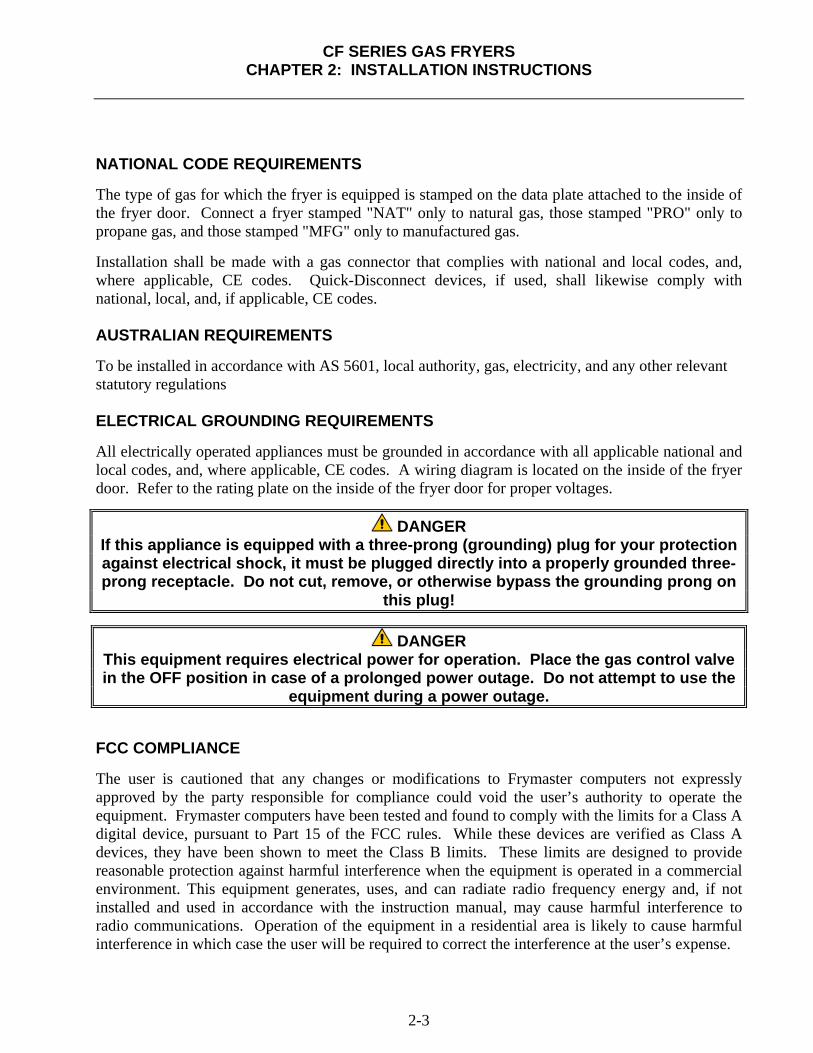
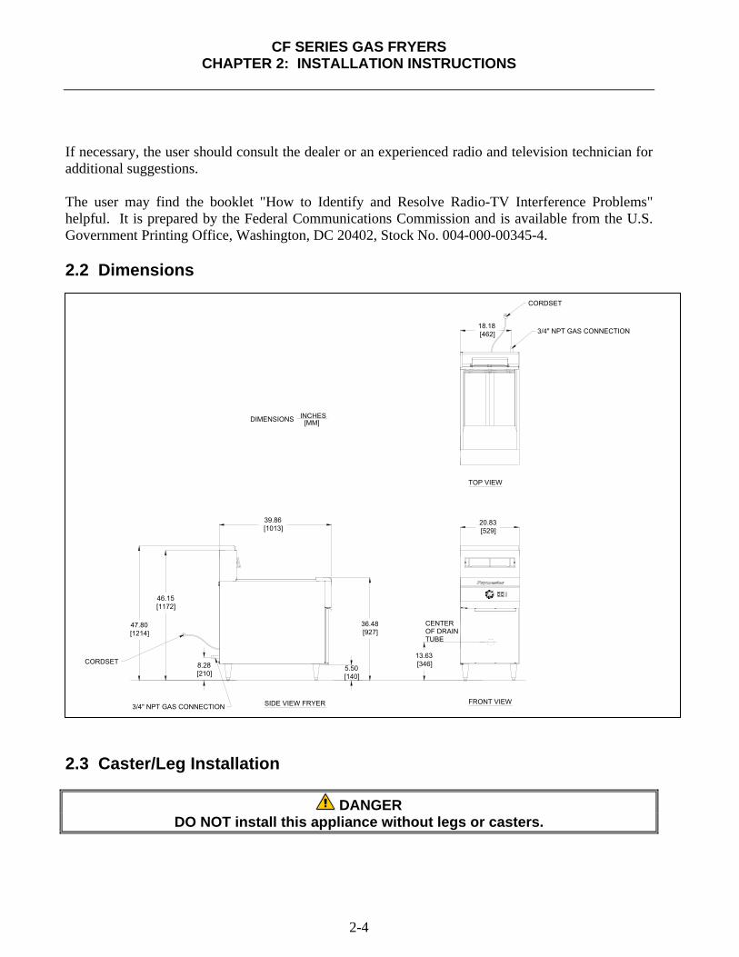

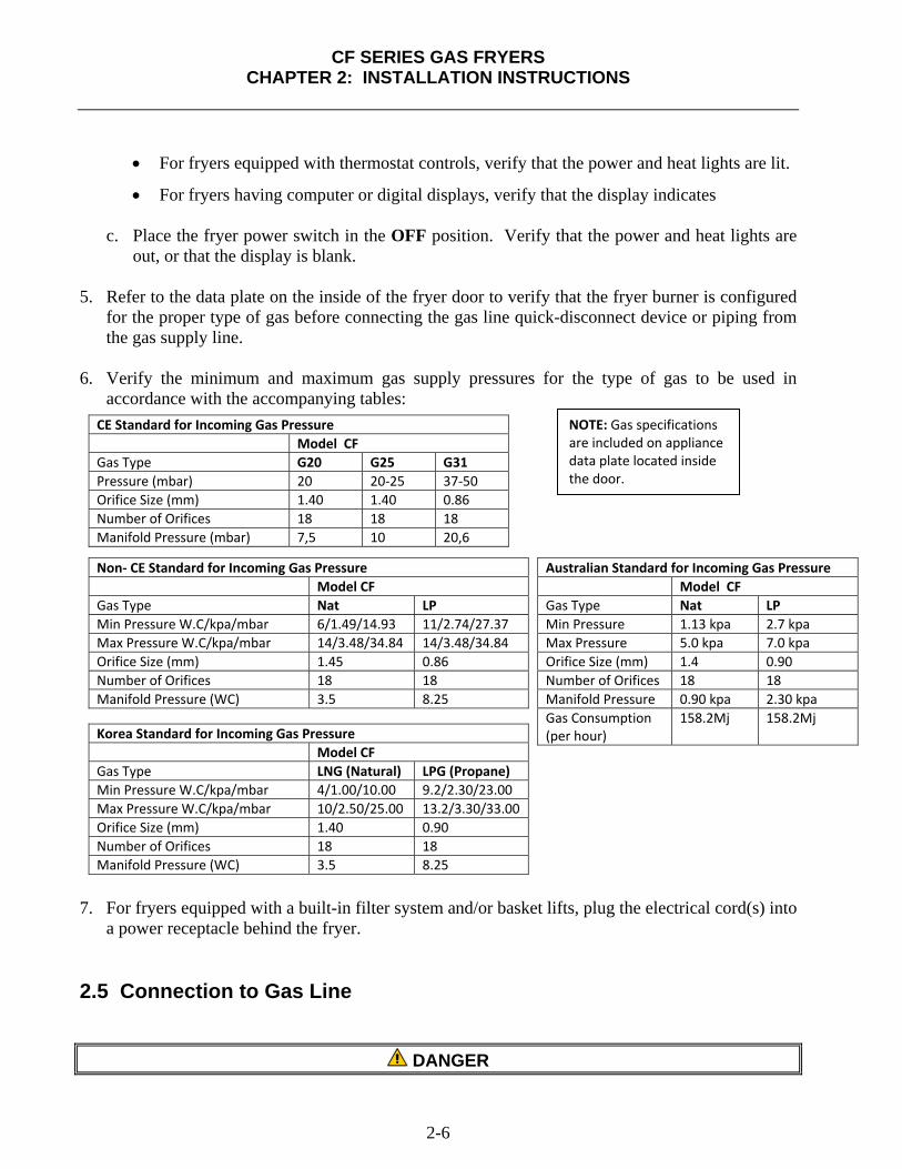
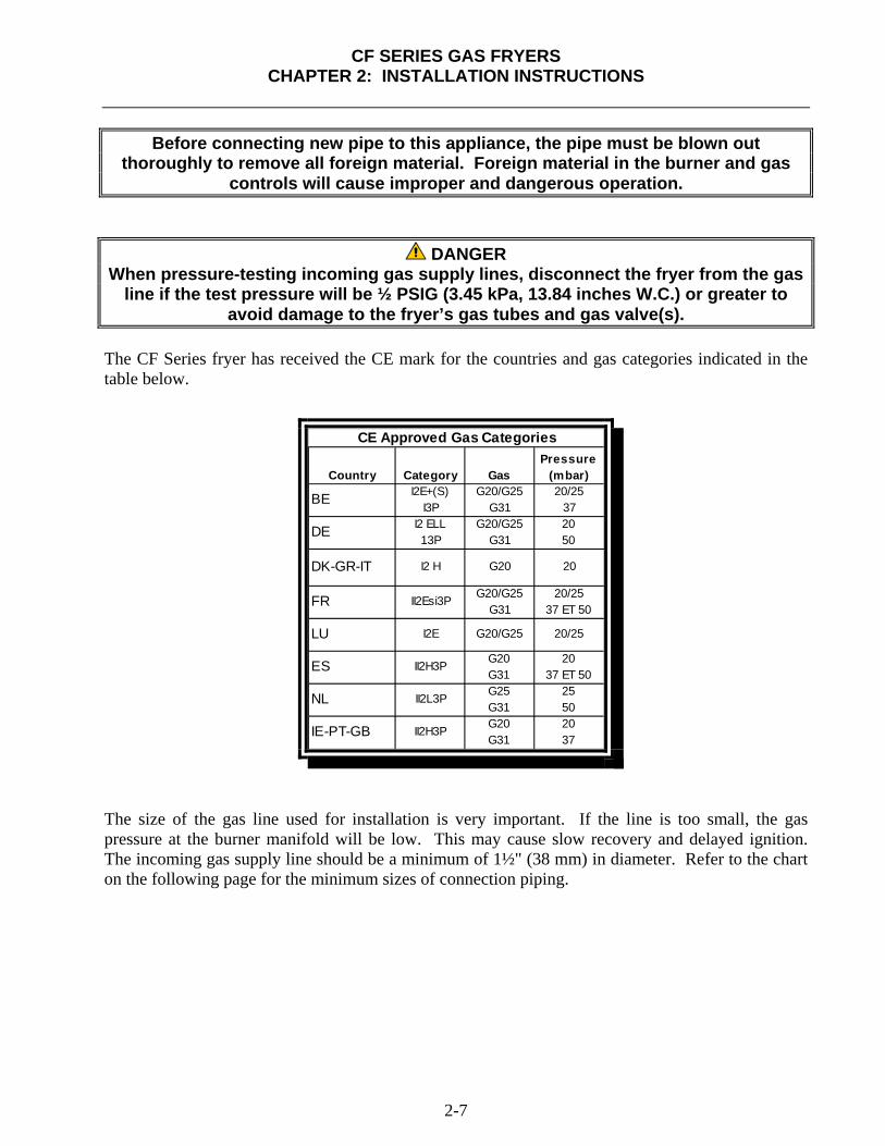

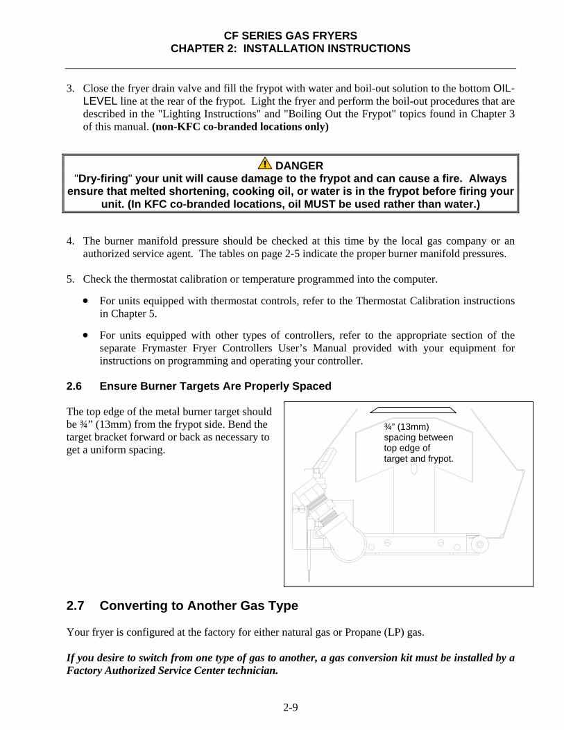


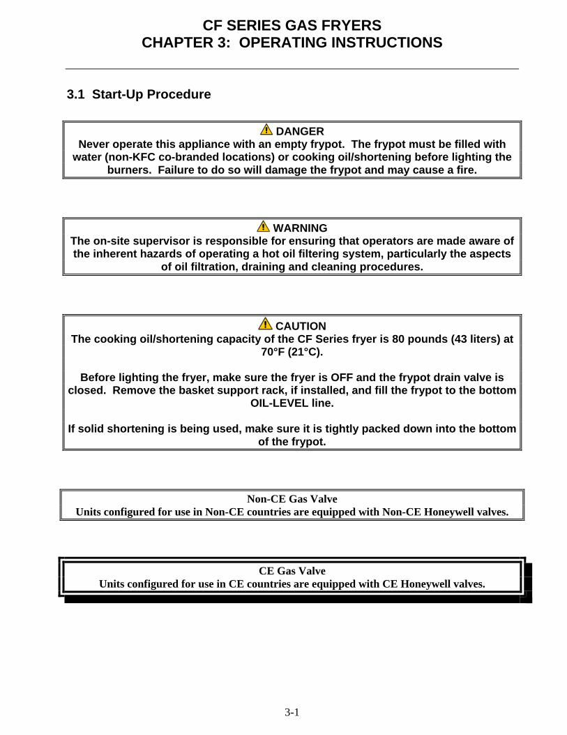


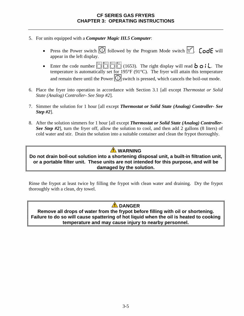


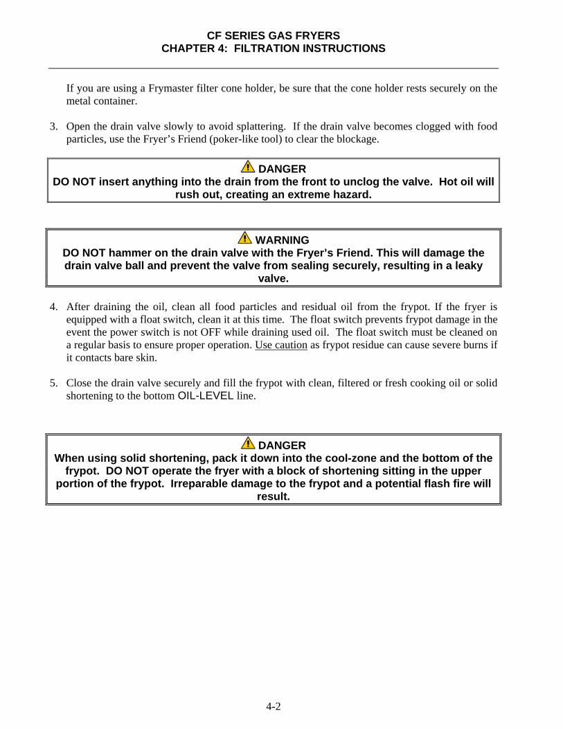
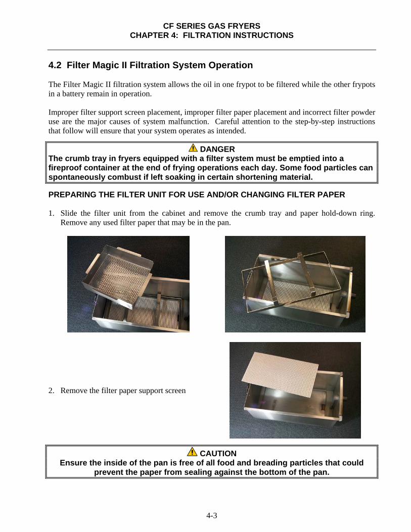
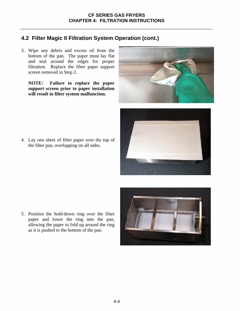
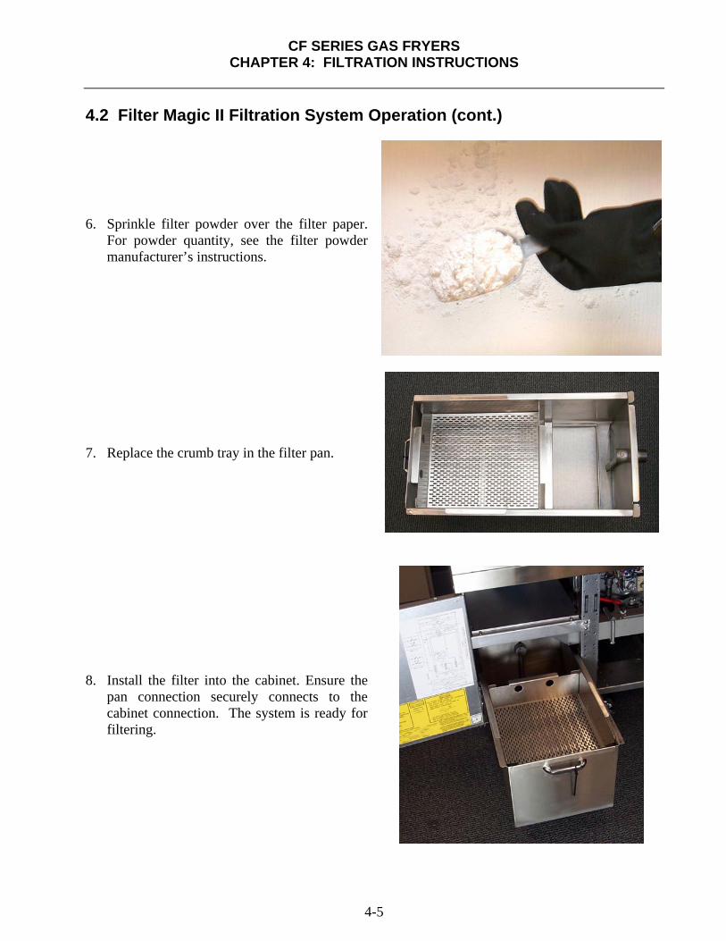

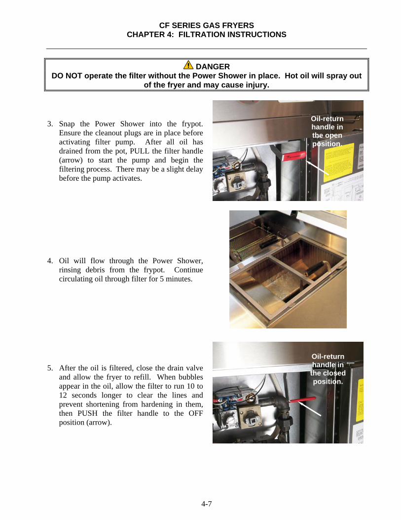


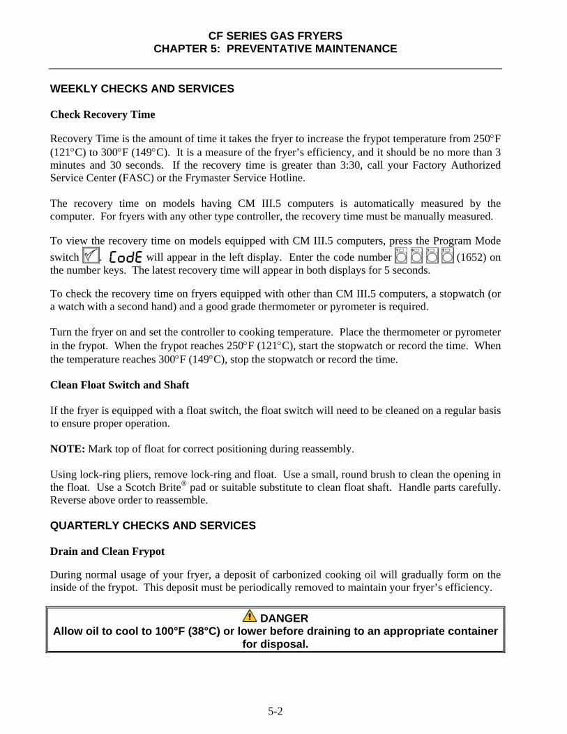


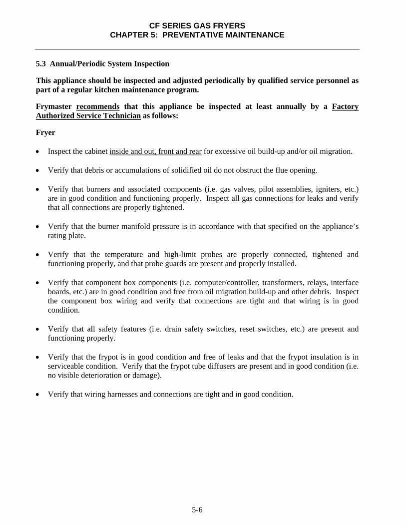


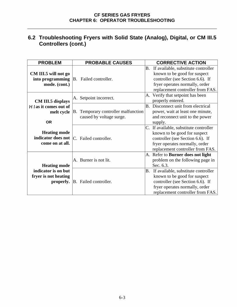

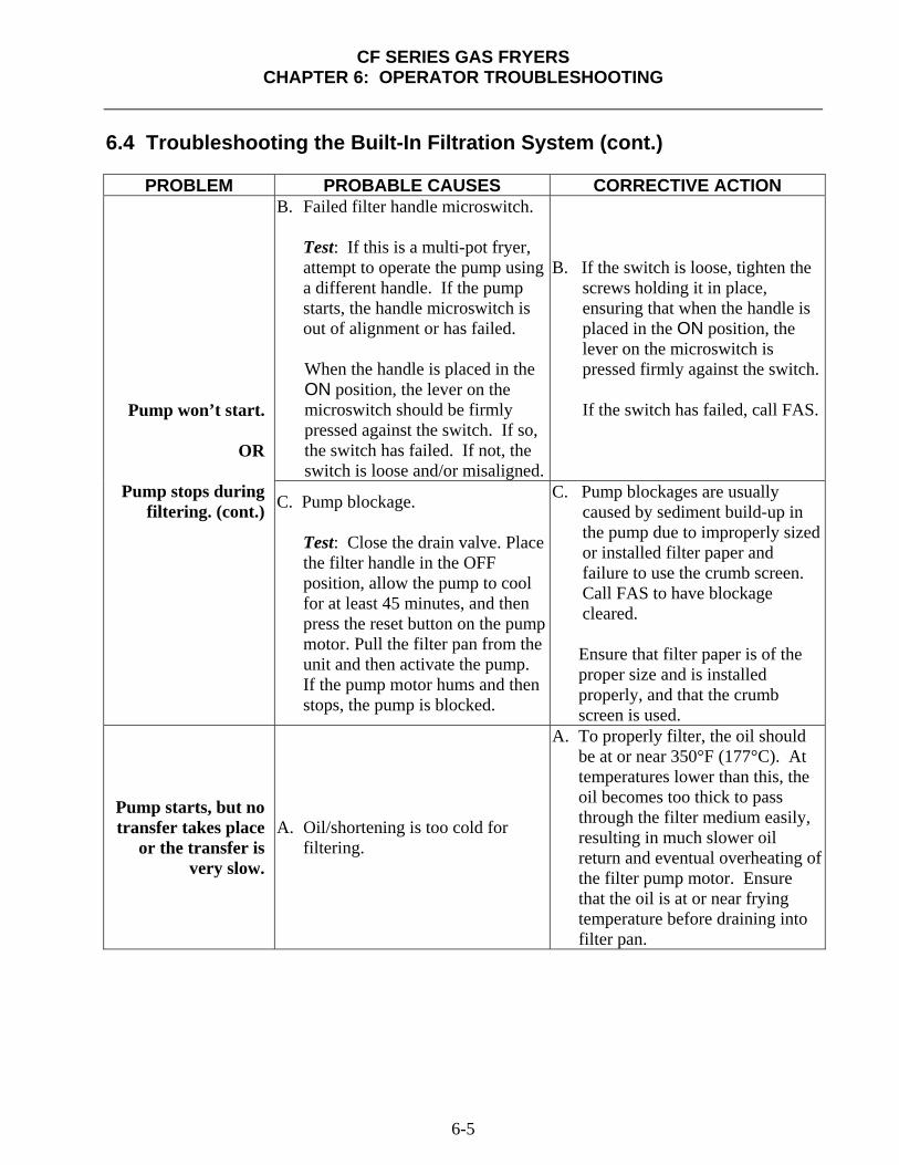


![GAS GOLDENFRY™ FRYERS - ANETS · VARIATION FOR YOUR APPLICATION. GAS GOLDENFRY™ FRYERS [P] 1.603.225.6684 [F] 1.603.225.8472 Administrative Office: 553 Route 3A Bow, NH 03304](https://static.documents.pub/doc/80x56/5f9f8d8f3419263b920eba0c/gas-goldenfrya-fryers-anets-variation-for-your-application-gas-goldenfrya.jpg)


