CFB Boiler Design for Indigenous Coals of Southern Africa Technical Paper BR-1949 Authors: J.P. Dacierno D.L. Kraft J.L. Remus J.W. Watson Babcock & Wilcox Barberton, Ohio, U.S.A. Presented to: Industrial Fluidization South Africa, IFSA 2017 Date: October 3-5, 2017 Location: Johannesburg, South Africa
Transcript
CFB Boiler Design for Indigenous Coals of Southern Africa
Abstract - A number of projects are planned in southern Africa that utilize circulating fluidized–bed (CFB) boiler technology to burn newly mined indigenous coals to produce steam for generation of electric power having low cost. The selected coals for these projects have 17.23 to 20.89 MJ/kg (7,406 to 8,981 Btu/lb) HHV basis and contain high levels of ash, sulfur and moisture. While the more traditional pulverized coal boilers can be designed to fire these fuels, CFB boilers have a stronger track record burning low-grade coals with less costly post-combustion pollutant treatment requirements. Since these plants will be located in remote locations they must operate independently and reliably with low maintenance, have flexibility to generate a wide range of steam capacity and be capable to follow load quickly. The success of each project will strongly depend on the boiler supplier’s ability to understand characteristics of unfamiliar coals and include critical design features needed for the CFB boiler to achieve its performance requirements in a reliable fashion.
INTRODUCTION Coal is a key energy source for Africa and for economic reasons future power generation projects are planned that will burn low-grade coal which contains high levels of ash, sulfur and moisture. Some projects will utilize indigenous coals coming from newly opened mines with combustion characteristics that are not well understood. Although the CFB boiler is well suited for this application, the coal characteristics, including chemistry from ash contained in the coal, can create a challenge for the boiler designer. The paper describes indigenous coals and emissions requirements recently encountered for projects in southern Africa and the design features that are necessary for the CFB to operate with these fuels.
Understanding coal ash chemistry is a critical aspect of the CFB boiler design process. Chemistry of certain compounds contained in coal ash can produce low melting point solids which cause the bed particles to become sticky, agglomerate with other bed material, and deposit scale on boiler surfaces. When faced with a new coal the CFB boiler designer must estimate fouling potential of different coals and apply methods to avoid or mitigate fouling. A technology development program optimized the U-beam solids recycle system and created the design for an optional in-bed heat exchanger that can provide fast load following. CFB boilers have operated more than 25 years with very high reliability, an important requirement for power generation in southern Africa. The paper covers chemistry of coal ash, availability numbers for different Babcock & Wilcox (B&W) CFB boilers, and the technology development program.
2
UNIQUE ASPECTS OF POWER PROJECTS IN AFRICA
Indigenous Coals
Power projects being considered in Africa require production of electric power at very low cost. Fuel is the largest operating cost component for such power plants and coal is the lowest cost boiler fuel in the region. Choosing the lowest cost coal that can be burned in the CFB boiler is of paramount importance. The lowest cost indigenous fuels being considered in central and southern Africa are low grade bituminous coals containing high levels of ash, moisture and sulfur:
• 17.23 to 20.89 MJ/kg (7,406 to 8,981 Btu/lb) HHV on an as received basis • Ash up to 37% • Moisture up to 15% • Sulfur up to 4.1%
Some indigenous coals have not previously been burned in large boiler systems, adding a degree of uncertainty to the CFB design. Furthermore, up to 37% of the mass of fuel feed to the boiler consists of coal ash which contains constituents like alkali and other compounds that melt at the temperatures of a CFB. An excessive amount of low melting point material in the bed of solids can lead to solids agglomeration and scaling problems on steam tubes and other equipment. Therefore, the boiler supplier must have a good understanding of the ash chemistry and correctly design the plant according to the ash and other properties of the selected coal. Chemical reactions in the CFB which result from different constituents in the coal ash are covered in the section Design for Chemistry of Coal Ash.
Independent Plants
The power plants under consideration are typically located near a coal or other mine or a production facility at a remote location. Some projects will be built to serve a small number of local industrial or mining facilities so the CFB and power turbine plants must be independent with the capability to operate over a range of steam capacities. They must also follow variable power loads quickly since there is usually no other source of steam or electric power generation in the area. Therefore the equipment must exhibit very high reliability with low maintenance. An optional in-bed heat exchanger (IBHX) which adds faster load following capability for the CFB boiler is described in the section Load Following Capability.
Environmental
Emissions requirements can vary depending on the local regulations and financing options. Generally speaking, the more stringent the emissions requirements imposed on a power plant, the more costly the plant will be, both from a capital and an operating expense perspective. A project’s financing source is often the key driver for the emissions requirements. The World Bank has set guidelines for emissions standards for the projects it finances.1 These guidelines have been applied to many projects in the developing world, even when the World Bank is not involved in the project funding as the emissions levels and necessary control equipment are generally well matched to the economic development of a region.
The World Bank guidelines are set at two levels: the Degraded Airshed (DA) and the Non-Degraded Airshed (NDA). DA limits are imposed for a new facility in an industrialized area where lower emissions are necessary to manage the overall pollutant levels in a region. The NDA limits apply when the new facility is in a lesser industrialized area where higher emissions levels are allowed. As industrialization can be a good indicator of the general economic development of an area, the DA and NDA classifications
3
loosely correlate with the ability of a region to support the cost of power. Projects in a region with higher economic development can afford the slightly higher electric power cost from a lower emitting plant.
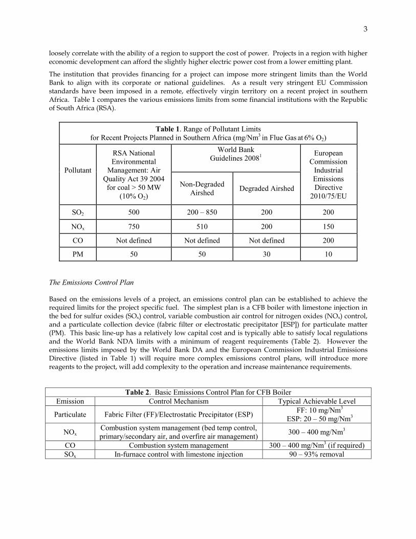
The institution that provides financing for a project can impose more stringent limits than the World Bank to align with its corporate or national guidelines. As a result very stringent EU Commission standards have been imposed in a remote, effectively virgin territory on a recent project in southern Africa. Table 1 compares the various emissions limits from some financial institutions with the Republic of South Africa (RSA).
Table 1. Range of Pollutant Limits for Recent Projects Planned in Southern Africa (mg/Nm3 in Flue Gas at 6% O2)
Pollutant
RSA National Environmental
Management: Air Quality Act 39 2004 for coal > 50 MW
(10% O2)
World Bank Guidelines 20081
European Commission
Industrial Emissions Directive
2010/75/EU Non-Degraded
Airshed Degraded Airshed
SO2 500 200 – 850 200 200
NOx 750 510 200 150
CO Not defined Not defined Not defined 200
PM 50 50 30 10
The Emissions Control Plan
Based on the emissions levels of a project, an emissions control plan can be established to achieve the required limits for the project specific fuel. The simplest plan is a CFB boiler with limestone injection in the bed for sulfur oxides (SOx) control, variable combustion air control for nitrogen oxides (NOx) control, and a particulate collection device (fabric filter or electrostatic precipitator [ESP]) for particulate matter (PM). This basic line-up has a relatively low capital cost and is typically able to satisfy local regulations and the World Bank NDA limits with a minimum of reagent requirements (Table 2). However the emissions limits imposed by the World Bank DA and the European Commission Industrial Emissions Directive (listed in Table 1) will require more complex emissions control plans, will introduce more reagents to the project, will add complexity to the operation and increase maintenance requirements.
Table 2. Basic Emissions Control Plan for CFB Boiler Emission Control Mechanism Typical Achievable Level
NOx Combustion system management (bed temp control, primary/secondary air, and overfire air management) 300 – 400 mg/Nm3
CO Combustion system management 300 – 400 mg/Nm3 (if required) SOx In-furnace control with limestone injection 90 – 93% removal
4
NOx
Limiting the NOx to the 200 mg/Nm3 level or lower will necessitate inclusion of either a selective non-catalytic reduction (SNCR) system or a selective catalytic reduction (SCR) system in the equipment train, and adds ammonia reagent to the operation of the plant.
CO
Adding a limitation on CO will impact the ability of the unit to achieve the required NOx levels – combustion conditions designed to limit NOx formation tend to promote CO formation, and vice-versa. Thus adding CO limitations will likely force the addition of an SNCR or SCR for NOx control, and in-furnace NOx production will increase. B&W has found CO catalyst technology to be unreliable and not cost effective.
SOx
Depending on the fuel chemistry, lowering limitations on SOx emissions can lead to the need for post-combustion SOx abatement technologies such as (listed in order of capital investment, lowest to highest) dry sorbent Injection (DSI), dry scrubbing (with CaO) or wet scrubbing with limestone (CaCO3) (wet flue gas dusulfurization). In-furnace limestone injection is limited to 90 to 93% removal. If the fuel sulfur and emissions requirements drive higher removal rates, the scrubbing technology will be selected based on the availability of reagents and process water.
PM
The base selection of an ESP or fabric filter for particulate collection is primarily based on the nature of the fuel ash. Highly resistive fuel ash, like some of the indigenous coals, will reduce the effectiveness of the electrostatic device, making the ESP larger and more capital cost intensive than a fabric filter. That higher capital cost needs to be weighed against the potentially higher operating cost of a fabric filter caused by the higher pressure drop and filter media replacement requirements. Therefore, PM emissions requirements can drive the decision towards a fabric filter when high ash resistivity is a factor.
IR-CFB BOILER FEATURES FOR INDIGENOUS COALS The B&W internal recirculating fluidized-bed (IR-CFB) boiler includes design features to handle challenging fuel characteristics of southern Africa. The design features necessary for successful operation of the CFB are described in this section. The side view of the boiler is shown in Figure 1.
Fuel and limestone sorbent are introduced with primary and secondary air into the fluidized bed of solids at the bottom of the IR-CFB boiler where combustion first occurs. The bed temperature is controlled in the range of 816 to 899°C (1500 to 1650°F) by careful design of heat transfer surfaces throughout the furnace. The low temperature range is necessary to control NOx and SOx emissions levels.
The gaseous products of combustion flow vertically upward through the furnace carrying a large loading of solid particles, and both solids and gases turn 90° and flow horizontally from the top of the furnace. Furnace exit gas and solids flow through three rows of U-beam particle collectors and then pass through the convection section and the mechanical dust collector before entering the air heater (Figure 1).
5
Figure 1. IR-CFB Boiler with IBHX for Fast Load Following
Two-Stage Particle Collection
By far the most important design feature of the IR-CFB boiler is the large recirculating load of solids which are captured and recycled in two stages:
• U-beams which efficiently capture and recycle the bulk of recirculating solids loading to the upper furnace; and
• Multi-cyclone dust collectors (MDC) which recycle finely sized particles into the lower furnace.
Two-stage particle collection provides a high degree of solids recirculation and intense gas/solids mixing conditions which support combustion of solid fuels that contain high levels of ash, sulfur and moisture at temperatures between 816 to 899°C (1500 to 1650°F) with low air emissions. Solids recirculation in the IR-CFB boiler has other benefits:
• Intense mixing of gases and solids promotes high heat transfer rates that over compensate for the relatively low temperature driving force for production of high temperature steam.
• High mass transfer rates between solids and gaseous compounds promote excellent chemical reaction rates for combustion and emissions control.
• Uniform temperature profile in the furnace for emissions control. • The low combustion temperature which is only possible with fluidized-bed combustion avoids
thermal NOx formation which is common in other boiler types including pulverized coal and stoker-fired boilers.
Low CFB combustion temperatures reduce the likelihood of scaling and agglomeration during combustion. However, there are limitations to the quantity and composition of ash contained in the fuel. Ash chemistry needs to be factored correctly into the design particularly when the ash contains a high level of alkali along with low alumina. This is covered in the section entitled Design for Chemistry of Coal Ash.
6
Stage 1 U-Beam Particle Collection
The first stage of solids capture and recycle is achieved by U-beams which are channel-shaped metallic beams designed for capturing 97% of the recirculation load of particles (Figure 2). Three rows of vertical U-beams are arranged across the entire width of the gas outlet in the top of the furnace. U-beams are oriented on a vertical axis such that furnace exit gas stream flows in a horizontal pattern perpendicular to each U-beam. Each U-beam consists of segments and each segment is supported independently from a water-cooled tube (Figure 3).
The gas stream and entrained particles flow directly into the open channel of each U-beam and this lowers the velocity of solids, trapping them between the two sides of U-beams. Trapped solids become disengaged from the gas stream and flow vertically downward. The flue gas combined with entrained particles flow horizontally around the side channels.
Figure 3. U-Beam Particle Collection, Stage One of Two-Stage Solids Separation
Legend A: Fuel and Sorbent Feed Solids B: Upwards Solids Flow C: U-Beam Recycle D: Solids recycle of MDC Capture E: Flue Gas/Fly Ash Exit F: Bed Drain
Stage 1 U-Beams
Stage 2 MDC
7
The detailed design of the U-beam system was recently optimized through a series of cold flow tests described in the section entitled Test Program to Design U-Beams and IBHX. The optimum arrangement contains only 3 rows of U-beams. Exit gas and solids leaving Row 1 pass into Row 2, exit gas and solids from Row 2 pass into Row 3 and exit gas and solids from Row 3 pass into the convection area of the boiler. The captured particles remain trapped between the two side channels of each U-beam, flow down each U-beam and discharge directly into the upper furnace where they become the main recirculating load of solids in the furnace.
Stage 2 MDC Particle Collection
The second stage consists of a bank of multi-cyclones following the convection section operating at a design temperature between 427 to 593°C (800 to 1100°F) depending on system design. The small metallic cyclones capture the smaller particles escaping the three U-beams which make up only 3% of the overall solids recirculation load. It is critical to recycle this relatively small quantity of finely sized particles to achieve high combustion efficiency and high rate of heat transfer in the IR-CFB boiler.
The solids from the MDC flow back into the furnace using air slides and vertical standpipes to ensure that these particles become discharged directly into the dense bed of solids in the lower furnace. There are storage hoppers below the MDC and the operator can independently control the solids level in the hopper and the solids discharge rate into the furnace to control the rate of heat transfer which governs the temperature inside the furnace (Figure 4).
Figure 4. Multi-cyclone Particle Collection, Stage Two of Two-Stage Solids Separation
Staged Combustion Conditions
A CFB furnace employs staged combustion conditions designed for approximately 40 to 60% of the total combustion air as primary air. The exact primary/secondary air ratio depends on fuel characteristics and emissions controls. Primary air enters through a number of bubble caps in the floor of the furnace. Secondary air enters through an array of nozzles approximately three meters above the bubble caps. The nozzles are designed to maintain flow patterns necessary for low emissions of NOx and CO.
8
Load Following Capability
An in-bed heat exchanger (IBHX) can be included in the bottom of the furnace (Figure 1) when faster load following is required. The final superheat and/or reheat surfaces are placed in the IBHX which features a bed of solids that are fluidized at low gas velocity. Heat transfer rates are high due to fine solids particle size and low fluidizing gas velocity. Bed sections in the IBHX can be turned on and off independently to follow load. Erosion of the steam tubes is very low at the fluidizing conditions of the IBHX. High temperature solids enter the IBHX from the lower furnace and they are fluidized by clean air. Since solid particles entering the IBHX have already undergone oxidation, the steam tubes are exposed to air which precludes corrosion of the metal tubes when the fuel contains corrosive elements.
Overall, the IBHX allows for: • Faster load following capability • Low maintenance • Compact design with less surface area
Fluidizing air enters the bed through the bubble caps and is controlled in different zones. Zone control allows the operator to fine-tune the behavior of the bed. Turning off the fluidizing air in a given zone results in a de-fluidized bed (also called “slumping”). The heat transferred in a given zone can be controlled from a very high value when it is fluidized to nearly zero by slumping the bed in the zone. This gives the operator better control of the superheater outlet temperature when the unit is ramping, and because the IBHX is coupled with the hot CFB bed, the availability of bed material ensures maintaining steam temperatures across the entire load range.
The design of the IBHX is such that the steam output can be ramped quickly up and down over a wide range of steam capacities while keeping other process parameters, such as steam temperature, within an acceptable tolerance band as required by the steam turbine. Ramping rate for steam temperature is 3 to 4% per minute using the IBHX compared to 1% per minute without the IBHX. The design of the turbine and balance of plant components must be coordinated with the boiler supplier to ensure all equipment is capable of handling these aggressive ramp rates.
Bottom Ash Cooler
Depending on the fuel composition, approximately 10 to 30% of total ash is discharged from the bottom of the CFB. It flows through a bottom ash cooler that utilizes fluidizing air, cooling tubes and membrane walls to cool the solids from 871°C (1600°F) to a discharge temperature of 204°C (400°F). The recovered energy is transferred to the water and steam circuit for increased boiler efficiency.
Reliability and Independent Operation of the IR-CFB Boiler Low Maintenance Features for IR-CFB Boiler
Indigenous fuels are often burned in remote locations which require boilers to be reliable and capable of operating independently. Maintenance work and boiler downtime must be reduced to the absolute minimum. The IR-CFB’s unique design requires significantly less maintenance compared to the cyclone CFB:
• Metallic materials selected for U-beams and MDC have low erosion for this service. • The dual solids collection system eliminates the refractory-lined cyclone, the cyclone inlet/outlet,
ducts, the loop seal and the high temperature expansion joint that are used in cyclone CFBs.
9
• For erosion protection the boiler membrane surfaces are protected in selected locations with a thin layer of high duty refractory with a high stud density for reduced erosion at conditions inside the CFB.
• Ceramic tiles cover tapered tubes in the interface zone between bare metal membrane water walls in the upper furnace and refractory-coated membrane wall in the lower furnace.
Thick refractory that lines the cyclones of other CFB boilers become damaged when its temperature changes faster than 56°C (100°F) per hour. The IR-CFB boiler can be ramped faster because it employs thin refractory linings inside the furnace and there are metallic components for the two-stage solids collection system. As a result, the IR-CFB boiler typically remains in operation about 14 hours longer each time the unit is shut down for maintenance. Furthermore the cyclone CFB is out of production for repairs between 3.5 to 7 days more based on feedback for the two different plants summarized in Tables 3 and 4.
Table 3. Cycle Time Required for CFB Boilers for Cold Startup and Cool Down
Scheduled maintenance of IR-CFB boilers normally requires 1 week for each year it operates. A typical cyclone CFB boiler requires 3 to 4 weeks downtime every two years to replace eroded sections of the refractory linings of the cyclones. The large diameter and tall height of refractory cyclones add extra down time to build and remove special scaffolding needed to access the hard to reach linings inside the inlet duct, barrel and cone sections of the large cyclones of a typical CFB. Combining the faster turn-around time (Table 3) and the reduced maintenance work that is required in a given year the IR-CFB boiler remains in production mode approximately 4 to 8 days longer each year compared to the cyclone CFB boiler.
Table 4. Scheduled Maintenance for CFB Boilers
IR‒CFB Cyclone CFB Scheduled maintenance period 1 week per year 3 ‒ 4 weeks every 2 years
Annual downtime for maintenance 1 week 1.5 ‒ 2 weeks
Major CFB repairs required Occasional Patching of refractory
Reline sections of cyclone refractory
Availability of Existing IR-CFB Boilers
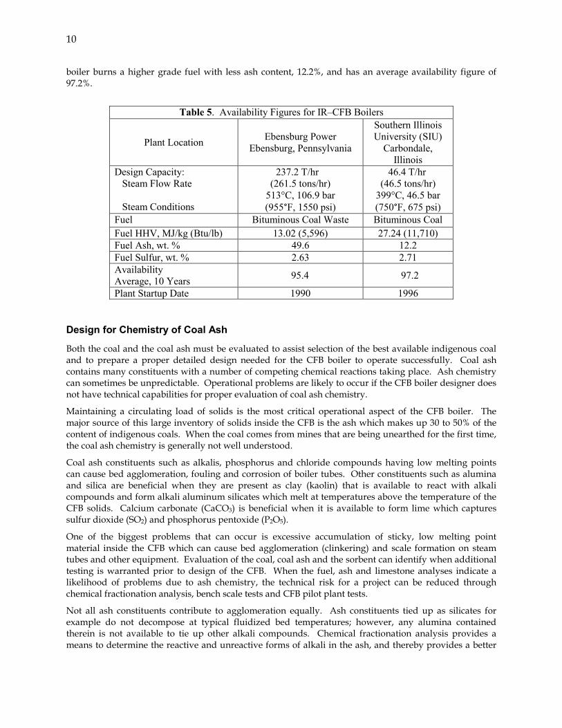
IR-CFB boilers do not require as much downtime for maintenance work due to the aforementioned design features. Availability figures for two different plants with similar coal types that have been operating more than two decades are presented to compare maintenance for low-grade and high-grade coals (Table 5). Average availability of two plants for the past 10 years is between 95 and 97%. Much of the downtime is not for maintenance of the CFB but required for the turbine section. The Ebensburg boiler, which has an average availability figure of 95.4%, burns a fuel with high ash content, 49.6%, which is closer to ash contained in indigenous coal of southern Africa. The Southern Illinois University (SIU)
10
boiler burns a higher grade fuel with less ash content, 12.2%, and has an average availability figure of 97.2%.
Table 5. Availability Figures for IR‒CFB Boilers
Plant Location Ebensburg Power Ebensburg, Pennsylvania
Both the coal and the coal ash must be evaluated to assist selection of the best available indigenous coal and to prepare a proper detailed design needed for the CFB boiler to operate successfully. Coal ash contains many constituents with a number of competing chemical reactions taking place. Ash chemistry can sometimes be unpredictable. Operational problems are likely to occur if the CFB boiler designer does not have technical capabilities for proper evaluation of coal ash chemistry.
Maintaining a circulating load of solids is the most critical operational aspect of the CFB boiler. The major source of this large inventory of solids inside the CFB is the ash which makes up 30 to 50% of the content of indigenous coals. When the coal comes from mines that are being unearthed for the first time, the coal ash chemistry is generally not well understood.
Coal ash constituents such as alkalis, phosphorus and chloride compounds having low melting points can cause bed agglomeration, fouling and corrosion of boiler tubes. Other constituents such as alumina and silica are beneficial when they are present as clay (kaolin) that is available to react with alkali compounds and form alkali aluminum silicates which melt at temperatures above the temperature of the CFB solids. Calcium carbonate (CaCO3) is beneficial when it is available to form lime which captures sulfur dioxide (SO2) and phosphorus pentoxide (P2O5).
One of the biggest problems that can occur is excessive accumulation of sticky, low melting point material inside the CFB which can cause bed agglomeration (clinkering) and scale formation on steam tubes and other equipment. Evaluation of the coal, coal ash and the sorbent can identify when additional testing is warranted prior to design of the CFB. When the fuel, ash and limestone analyses indicate a likelihood of problems due to ash chemistry, the technical risk for a project can be reduced through chemical fractionation analysis, bench scale tests and CFB pilot plant tests.
Not all ash constituents contribute to agglomeration equally. Ash constituents tied up as silicates for example do not decompose at typical fluidized bed temperatures; however, any alumina contained therein is not available to tie up other alkali compounds. Chemical fractionation analysis provides a means to determine the reactive and unreactive forms of alkali in the ash, and thereby provides a better
11
indication of agglomeration potential. B&W has developed bench-scale tests whereby agglomeration potential as a function of solids chemistry can be determined at CFB operating temperatures.
A summary of the different ash constituents and some general rules about competing chemical reactions that occur at conditions in the CFB are shown in Table 6. There are a few predictable chemical reactions which will take place as long as the reactants are present in excess of the required stoichiometry:
1. Alkali constituents (Na2O and K2O) can react to form low melting salts but alkalis are tied up by alumina and silica to form alkali aluminum silicates with higher melting point temperatures. Clay has been used for a number of years as an additive to raise the melting point in different fluidized-bed systems. A recent fluidized-bed pilot plant test program funded by the United States Department of Energy (U.S. DOE) demonstrated how clay raises the melting point using the phase diagram for Na2O, SiO2 and Al2O3.2
2. P2O5 is highly reactive and it will react with anions to form low melting compounds but it will become tied up by an excess of calcium to form tri-calcium phosphate.
P2O5 + 3CaO Ca3(PO4)2 1670 °C (3038°F) melting point
3. Aluminum liberates phosphates. For example, it breaks the Na - (PO4) bond to form sodium aluminum silicate when there is excess silica. This liberates reactive phosphate groups which can proceed to form unstable compounds such as iron phosphates.
4. SO3 in the ash needs to be considered in determination of sulfur capture and limestone requirements. Any CaO in the ash is available to react with sulfur.
Chloride chemistry is not as predictable, yet chlorides in fuel can be a source of both metal corrosion and bed agglomeration problems in the CFB. When the chloride content of the coal exceeds 0.1%, metal corrosion in the furnace can be problematic depending on other parameters such as steam and metal conditions. At best only a small portion of the chlorides in the feed can be captured with supplemental feeding of clay. Clay addition has been demonstrated to tie up the alkali component in metal chlorides fed into a fluidized bed waste incinerator with feed ratio Al2O3/Na2O = 3.3 (mass basis) but chlorides are not tied up and they remain as volatile compounds.3 Bench and/or CFB pilot plant testing would be required to evaluate bed agglomeration, HCl level in furnace gas, scaling, and feasibility of additives to control low melting compounds and capture chlorides.
12
Table 6. Bed Agglomeration from Fuel Constituents Rules of Thumb, Potential Agglomeration Signs and Control Methods for High Ash Fuels*
Constituent Role in Bed Agglomeration & Scaling
Design & Control Methods to Avoid Difficulty from Fluid Bed Solids
Diagnostic Test
CaO
• Excessive free lime can build up on steam tubes in convection section and other areas.
• Lime will become sulfated from long term contact with SO2 forming hard scale.
• Avoid very excessive lime in the ash, particularly fine particle sized lime.
• Proper design of sootblowers in convection passes.
• Conservative design by reducing gas velocity in convection passes.
Available lime content. CFB combustion testing using actual fuel and limestone can help predict agglomeration and scaling potential.
Alkali Compounds
Na2O and K2O
• Alkali compounds have low melting points which cause sticky bed particles, bed agglomeration and scaling of heat transfer surfaces.
• When alkalis accumulate to a high level, the bed can become agglomerated and de-fluidized with poor hydro-dynamics; the unit must be shut down for cleaning and bed removal.
• Aluminum silicate (clay) helps reduce agglomeration by increasing the melting point of bed solids. Alkali compounds become tied up with alumina and silica forming clay (alkali aluminum silicates) which has a higher melting point.
• Limit alkali in the feed: o Total alkali, 0.25 g/MJ o Alumina/(Na2O+K2O) > (2.2-3.3)/1
(wt. basis) o Add alumina as needed (kaolin clay) o Control alkali accumulation by
adjusting bed drain rate.
Check free alkali in fuel; chemical analysis (water soluble alkali) and chemical fractionation. Bench and pilot plant tests are necessary to evaluate clay addition.
P2O5
P2O5 is highly reactive and it can react with Fe, Na and Ca compounds to form compounds having low melting points, particularly when present in combination with iron.
Tie up phosphorous as tri-calcium phosphate. Sufficient available calcium (water soluble) from fuel plus excess limestone feed must be present to react with phosphate and form the stable tri calcium phosphate Ca3 (PO4)2 with higher melting point.
Check available calcium and phosphate content. Test work is required to validate desired chemistry.
Al2O3
Alumina is beneficial because it ties up alkalis to raise the melting point above the furnace temperature.
• See alkali compounds above. • Available alumina and silica must be
present in stoichiometric amounts that are necessary for beneficial chemical reactions to occur.
Bench testing at a minimum is required to measure the amount of available alumina and silica and to validate desired chemistry.
SiO2
Silica is a key ingredient to form clays which are beneficial for raising melting point of the bed of solids.
Chloride Compounds
Chlorine is difficult to capture. Clay addition might capture alkali species from alkali chloride but this will liberate chlorine.
• Keep chloride content below 0.1% of the coal to help manage metal corrosion, depending on steam and metal conditions.
Bench and pilot plant tests are necessary to evaluate clay addition.
*This table is based on commercial experience with different fluidized-bed combustion systems where bed agglomeration due to constituents in the feed is controlled.
13
Test Program to Design U-Beams and IBHX
B&W recently optimized the design of the U-beam particulate recirculation equipment together with the IBHX through a series of CFB pilot plant tests using two different test facilities. Major U-beam design improvements from this effort are summarized in Table 7. The test program and results for the two-stage recycle system are described below.
Table 7. Results from Development Program for the U-Beam System
Design Improvement Description Benefits of New Design
Reduce the number of U-beams, change arrangement of U-beams and include a segmented U-beam design.
The number of U-beams needed to separate and recycle the bulk of the solids re-circulation mass was reduced.
• High particle collection efficiency
• More compact design • Segmented U-beams have
improved thermal tolerance, longer lifetime and less maintenance requirement.
Inclined screw conveyors were replaced with gravity flow air slides to transport the MDC discharge stream into gravity feed pipes that discharge into furnace.
Gravity air slides convey the fine sized particles with less effort using smaller equipment and less height requirement.
Two test facilities, a 2.5 MWth hot pilot facility and a 1/4 scale cold model of the hot pilot were required to develop hydrodynamics and design criteria for the U-beams and the IBHX. Both facilities include a CFB furnace and an internal fluid bed heat exchanger (IBHX) on the furnace rear wall. The IBHX is optional depending on fuel characteristics, steam conditions, unit turndown requirements, and unit ramping requirements. All modifications to the hot pilot were first demonstrated on the cold model. Every observation seen on the cold model was observed on the hot pilot.
Operating parameters for the cold flow model were scaled between hot to cold CFB boiler pilot plants according to methods from Glicksman, et. al.4 The range of modeling parameters between hot to cold flow units varied as follows:
• 1/2 velocity • 1/4 particle size • 125 micron iron particles • Iron particles with high density, 8900 kg/m3 (555 lb/ft3)
The cold model is constructed of Plexiglas® to visually observe furnace hydrodynamics (Figure 5). Using the cold model, results obtained from the simulation were tuned and furnace hydrodynamics were verified for various furnace operating conditions. Upon achieving hydrodynamic verification the cold flow pilot plant results were implemented into the hot pilot plant for performance validation.
The 2.5 MWth hot pilot plant features adjustable underflow ports, overflow ports, partition wall height, tube bundle arrangement and bubble cap arrangement (Figure 6). It is large enough to simulate full-scale hydrodynamics including full scale height in the primary zone to characterize solids flow into the heat
14
exchanger. Solid particles containing fixed carbon entered the IBHX from above. The degree of carbon combustion in the IBHX and rate of heat transfer within the IBHX were measured to confirm both local and overall heat transfer characteristics.
Figure 5. Cold Flow Model Constructed of Plexiglas®, ¼ Scale of Hot Pilot Plant, Used to Validate System Hydrodynamics
Figure 6. Pilot Plant 2.5 MWth Pilot Plant with U-Beams and IBHX
Results from U-beam Optimization Tests
A customized cold flow model was built and operated in a test program to measure U-beam collection efficiencies for a number of U-beam arrangements. Particle collection efficiency for each row of U-beams was measured individually. Analysis of test data showed that the optimum U-beam arrangement utilizes only three rows of U-beams and only the first U-beam needs to be located in the furnace. Particle collection efficiency for three U-beam rows is four percentage points higher than particle collection efficiency for four rows of U-beams.
Results showed that the second row of U-beams in the furnace is not necessary. Particle collection efficiency with three U-beams having the first U-beam in furnace is greater than when employing four U-beams having two U-beams in the furnace.
In every case, the second U-beam row separates particles with higher efficiency than the first row. The flue gas and solids discharged from the first row are much more concentrated and focused directly into the second U-beam resulting in greater solids collection efficiency. For the three row arrangement, the second row discharge stream is similarly directed into the third U-beam row, but its solids collection efficiency is somewhat reduced compared to the second U-beam because solids concentration is lower. In addition, for the 2x2 row arrangement the gas and solids expand between the second and third rows. The third row is once again a straightener for the fourth row, which is an inefficient use of the third row. With the three row arrangement, the efficiency gain over the 2x2 and the simple two row arrangement was the collection of the more efficient third row.
15
Benefits from the Optimized Design of Two-Stage Particle Recirculation System
• A design having three rows of U-beams instead of four has a more compact size with less weight, reduced boiler depth and higher solids collection efficiency.
• Segmented U-beam design results in extended lifetime of U-beams and very low maintenance requirement.
• Metallic U-beams provide faster temperature ramp rates during start up, shut down and load changes, especially compared to a hot cyclone. The boiler can be heated from ambient to a nominal 871°C (1600°F) operating temperature in only 10 hours and it can be cooled down from 871°C (1600°F) to a temperature suitable for lower furnace entry in only 8 hours (Table 3).
• Air slides provide for independent recycle flow control of MDC solids, smaller equipment and faster flow response compared to a screw conveyor.
REFERENCES 1. International Finance Corporation, World Bank Group, Environmental, Health and Safety
Guidelines for Thermal Power Plants, December 2008: p 22. 2. Thor Treatment Technologies, LLC, Report for Treating Hanford LAW and WTP SW Simulants:
Pilot Plant Mineralizing Flowsheet, 2009: Figure 2-1 p 2-2. 3. U.S. Patent 3907674, Dorr-Oliver, Inc. (Stamford CT), Fluidized Bed Incineration of Wastes
Containing Alkali Metal Chlorides, 1975. 4. Glicksman, L.R., Hyre, M. and Woloshun, K., Simplified Scaling Relationships for Fluidized Beds,
Powder Technology, 1993: 177-179.
ACKNOWLEDGMENTS Cold model and 2.5 MWth CFB Pilot Plant testing were both performed by Southeast University of China.