Vol.50, No.3 /2016 INMATEH –111 CFD STUDY OF A SWEEP-TWIST HORIZONTAL AXIS WIND TURBINE BLADE / BOYUNA-EĞİMLİ BİR YATAY EKSENLİ RÜZGÂR TÜRBİNİ KANADININ HAD ÇALIŞMASI Ph.D. Stud. Eng. Kaya M. N.* 1) , Asst. Prof. Ph.D. Eng. Köse F. 2) 1) Karamanoglu Mehmetbey University, Engineering Faculty, Mechanical Engineering Department, Karaman / Turkey 2) Selcuk University, Engineering Faculty, Mechanical Engineering Department, Konya / Turkey Tel: +90 3382262000-5067; E-mail: [email protected]Keywords: wind, turbine, blade, performance, sweep, twist ABSTRACT Wind energy is being used to generate electricity in many countries all over the world and still the contribution of wind energy to electricity supply increases every day. Researchers work on innovative solutions to increase the efficiency and decrease the cost of wind turbine components, especially those of blades. Various blade designs for different operation conditions are presented in the literature and sweep- twist blades are new type of blades introduced recently. This paper focuses on the numerical investigation of a sweep-twist wind turbine blade using ANSYS-Fluent. NREL Phase VI wind turbine blade is used as the baseline blade and the sweep-twist blade is designed by adding an offset that is 5% of the blade span to the tip. Power output and thrust forces are calculated using the simulation results for both original and sweep blades. In addition, results are compared to the experimental data of original NREL Phase VI blade. ÖZET Rüzgâr enerjisi elektrik üretmek amacıyla dünyada birçok ülkede kullanılmaktadır ve rüzgâr enerjisinin elektrik üretimine katkısında günden güne yükselmektedir. Araştırmacılar rüzgâr türbini bileşenlerinin – özellikle kanatların - verimlerinin arttırılması ve maliyetlerinin azaltılması için yenilikçi çözümler üzerinde durmaktadırlar. Literatürde çeşitli çalışma koşulları için değişik tasarımlar mevcut olup, eğimli kanatlar bunlardan biridir. Bu çalışmada ANSYS-Fluent programı ile eğimli bir rüzgâr türbini kanadının numerik analizi üstünde durulmuştur. NREL Faz VI rüzgâr türbini kanadı baz alınmış ve eğimli kanadı ise uç kısmına kanat boyunun %5’si kadar eğim verilerek tasarlanmıştır. Güç çıkışları ve itme kuvvetleri simülasyon sonuçlarına göre hesaplanmıştır. Buna ek olarak, sonuçlar NREL Faz VI rüzgâr türbininin deneysel sonuçları ile karşılaştırılmıştır. INTRODUCTION Each passing day the need for the use of clean energy sources raises since power production from fossil fuels damage our planet continuously. Within this scope, many developed and developing countries have set some goals to generate some part of energy consumption from renewable energy sources. For instance, the ministry of energy of Turkey has decelerated in the strategic plan for 2015-2019 an increase in installed renewable energy capacity by nearly twice compared to the value of 2013 (GWEC, 2016; Kaya and Köse, 2016; Köse and Kaya, 2013; MENS, 2014). Hence, wind energy – recognized as an efficient renewable energy source – has taken the role of being one of the leading alternative sources. In past few decades, huge improvements have taken place in wind power technology especially on the design of blades which influences the efficiency directly. Within this scope, many experts who are interested in aerodynamics contributed to the literature with some studies about various blade designs. Sweep-twist wind turbine blades were firstly introduced by Sandia National Laboratories of U.S. Energy Department. After completing the research, they presented a final report (2010) where they introduced analysis results of Sweep Twist Adaptive Rotor (STAR) blades. In the report, they stated that the STAR technology provided significantly greater energy capture – about 10-12% compared to baseline Z48 turbines - without higher operating loads on the turbine. The results are also presented by Ashwill et al. (2010). Sing and Ahmed (2013) performed a study about design and performance testing of a small wind turbine rotor for low wind speed applications. A new airfoil was designed and the performance of a 2-bladed rotor for low Re application fitted to an Air-X marine 400 W wind turbine was tested at a wind speed range of 3-6 m/s. Authors stated that the new 2- bladed rotor produced more electrical power at the same freestream velocity in comparison with the baseline
Transcript
Vol.50, No.3 /2016 INMATEH –
111
CFD STUDY OF A SWEEP-TWIST HORIZONTAL AXIS WIND TURBINE BLADE/
BOYUNA-EĞİMLİ BİR YATAY EKSENLİ RÜZGÂR TÜRBİNİ KANADININHAD ÇALIŞMASI
Ph.D. Stud. Eng. Kaya M. N.*1), Asst. Prof. Ph.D. Eng. Köse F.2)
ABSTRACTWind energy is being used to generate electricity in many countries all over the world and still the
contribution of wind energy to electricity supply increases every day. Researchers work on innovativesolutions to increase the efficiency and decrease the cost of wind turbine components, especially those ofblades. Various blade designs for different operation conditions are presented in the literature and sweep-twist blades are new type of blades introduced recently. This paper focuses on the numerical investigation ofa sweep-twist wind turbine blade using ANSYS-Fluent. NREL Phase VI wind turbine blade is used as thebaseline blade and the sweep-twist blade is designed by adding an offset that is 5% of the blade span to thetip. Power output and thrust forces are calculated using the simulation results for both original and sweepblades. In addition, results are compared to the experimental data of original NREL Phase VI blade.
ÖZETRüzgâr enerjisi elektrik üretmek amacıyla dünyada birçok ülkede kullanılmaktadır ve rüzgâr enerjisinin
elektrik üretimine katkısında günden güne yükselmektedir. Araştırmacılar rüzgâr türbini bileşenlerinin –özellikle kanatların - verimlerinin arttırılması ve maliyetlerinin azaltılması için yenilikçi çözümler üzerindedurmaktadırlar. Literatürde çeşitli çalışma koşulları için değişik tasarımlar mevcut olup, eğimli kanatlarbunlardan biridir. Bu çalışmada ANSYS-Fluent programı ile eğimli bir rüzgâr türbini kanadının numerik analiziüstünde durulmuştur. NREL Faz VI rüzgâr türbini kanadı baz alınmış ve eğimli kanadı ise uç kısmına kanatboyunun %5’si kadar eğim verilerek tasarlanmıştır. Güç çıkışları ve itme kuvvetleri simülasyon sonuçlarınagöre hesaplanmıştır. Buna ek olarak, sonuçlar NREL Faz VI rüzgâr türbininin deneysel sonuçları ilekarşılaştırılmıştır.
INTRODUCTIONEach passing day the need for the use of clean energy sources raises since power production from
fossil fuels damage our planet continuously. Within this scope, many developed and developing countrieshave set some goals to generate some part of energy consumption from renewable energy sources. Forinstance, the ministry of energy of Turkey has decelerated in the strategic plan for 2015-2019 an increase ininstalled renewable energy capacity by nearly twice compared to the value of 2013 (GWEC, 2016; Kaya andKöse, 2016; Köse and Kaya, 2013; MENS, 2014). Hence, wind energy – recognized as an efficientrenewable energy source – has taken the role of being one of the leading alternative sources. In past fewdecades, huge improvements have taken place in wind power technology especially on the design of bladeswhich influences the efficiency directly. Within this scope, many experts who are interested in aerodynamicscontributed to the literature with some studies about various blade designs. Sweep-twist wind turbine bladeswere firstly introduced by Sandia National Laboratories of U.S. Energy Department. After completing theresearch, they presented a final report (2010) where they introduced analysis results of Sweep TwistAdaptive Rotor (STAR) blades. In the report, they stated that the STAR technology provided significantlygreater energy capture – about 10-12% compared to baseline Z48 turbines - without higher operating loadson the turbine. The results are also presented by Ashwill et al. (2010). Sing and Ahmed (2013) performed astudy about design and performance testing of a small wind turbine rotor for low wind speed applications. Anew airfoil was designed and the performance of a 2-bladed rotor for low Re application fitted to an Air-Xmarine 400 W wind turbine was tested at a wind speed range of 3-6 m/s. Authors stated that the new 2-bladed rotor produced more electrical power at the same freestream velocity in comparison with the baseline
Vol.50, No.3 /2016 INMATEH –
112
3-bladed rotor. Wang and Zhan (2013) investigated the performance of a micro-wind turbine using CFD andconcluded that the performance of the wind rotor with semi-circular blades is comparable to that of the semi-cylindrical wind rotor, and is slightly lower than that of the helically twisted wind rotor. Bai et al. (2013)designed a 10 kW horizontal axis wind turbine blade and performed aerodynamic investigation usingnumerical simulation of it. It has been reported that CFD is a good method compared to the improved BEMtheory method on the aerodynamic investigation of HAWT blades. Koc et al. (2015) studied thehydrodynamic performance of a twin-blade hydrofoil numerically and experimentally in three dimensions fortip speed ratios ranging between 1.5 and 5.5. Authors reported that the optimum tip speed ratio of 3.5 fortwin blade turbine is too low comparing the optimum tip speed ratio of 5.0 for the slat hydrofoil or standardhydrofoil turbine applications and added that the wind and hydrokinetic turbines with the twin blade hydrofoilcan operate in lower wind and current speeds. A detailed review of aerodynamic developments on smallhorizontal axis wind turbine blades is presented by Kartikeyan (2015). In the present study, numericalinvestigation of the aerodynamics around a sweep-twist wind turbine blade using ANSYS-Fluent isperformed. NREL Phase VI wind turbine blade is used as a baseline blade and the sweep-twist blade isdesigned by adding an offset to the tip as that is 5% of the blade diameter. Results are compared with theoriginal NREL Phase VI wind turbine.
MATERIAL AND METHODNREL Phase VI and Sweep-Twist Blade
NREL Phase VI wind turbine blade is selected as a baseline blade. It has S809 airfoil sections fromroot to tip and a pitch angle of 3 degrees. The description of the NREL Phase VI blade is given in Table 1(Hand et al., 2001). In this study, some sections including the ones which have radial distance between0.660 and 1.257 and the one with 3.185 radial distance are excluded since the sections are very close to theprevious section.
Table1Description of NREL Phase VI (Hand et al., 2001)
Number of blades 2Rotor diameter 10.06 mCone angle 0 degreesRPM 71.6Blade tip pitch angle 3 degrees (down)Blade profile S809Blade chord length 0.358 m – 0.728 m (linearly tapered)Twist angle Non-linear twist along the span
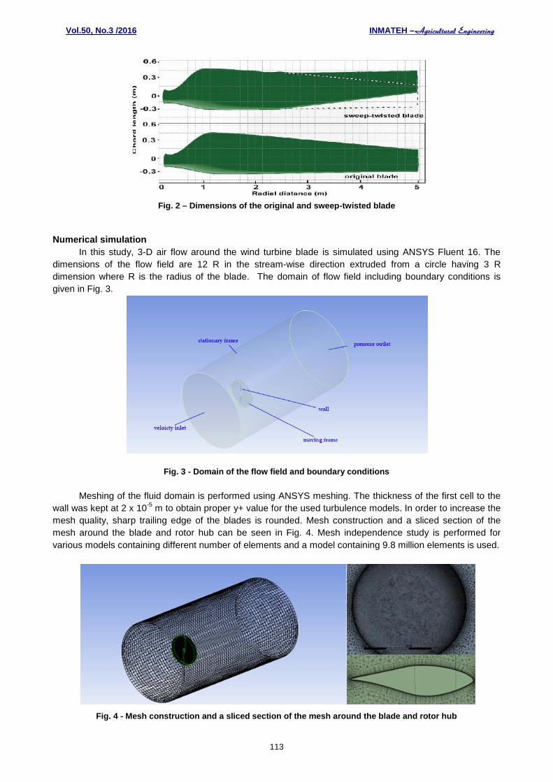
The 3-D drawings of the blades are given in Fig. 1. To draw the sweep-twist blade, all the sameproperties as NREL Phase VI blade are used except a root axis tip offset which is 5% of the blade diameter(0.25 m). Offsets of each sectionfrom the beginning of the sweep – located at the 2.562 m radial distance-until the tip of the blade are calculated interpolation method. Dimensions of the original and sweep-twistedblades are given in Fig. 2.
Fig. 1 – 3D drawings of the NREL PHASE VI (left) and sweep-twisted blade (right)
Vol.50, No.3 /2016 INMATEH –
113
Fig. 2 – Dimensions of the original and sweep-twisted blade
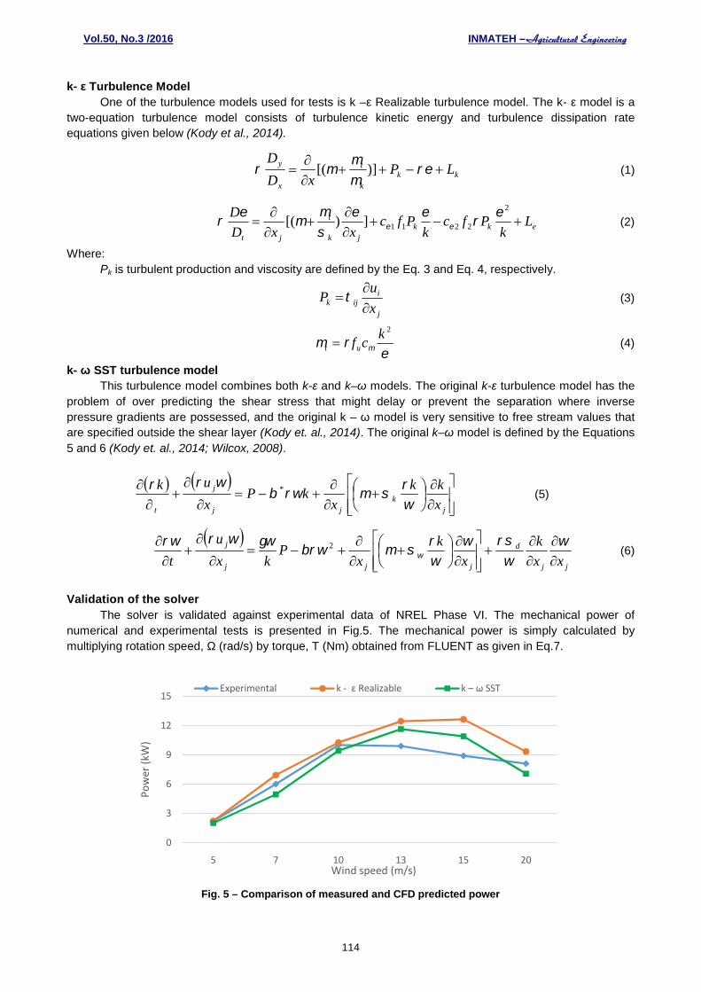
Numerical simulationIn this study, 3-D air flow around the wind turbine blade is simulated using ANSYS Fluent 16. The
dimensions of the flow field are 12 R in the stream-wise direction extruded from a circle having 3 Rdimension where R is the radius of the blade. The domain of flow field including boundary conditions isgiven in Fig. 3.
Fig. 3 - Domain of the flow field and boundary conditions
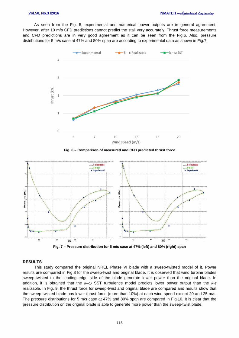
Meshing of the fluid domain is performed using ANSYS meshing. The thickness of the first cell to thewall was kept at 2 x 10⁻⁵ m to obtain proper y+ value for the used turbulence models. In order to increase themesh quality, sharp trailing edge of the blades is rounded. Mesh construction and a sliced section of themesh around the blade and rotor hub can be seen in Fig. 4. Mesh independence study is performed forvarious models containing different number of elements and a model containing 9.8 million elements is used.
Fig. 4 - Mesh construction and a sliced section of the mesh around the blade and rotor hub
Vol.50, No.3 /2016 INMATEH –
114
k- ε Turbulence ModelOne of the turbulence models used for tests is k –ε Realizable turbulence model. The k- ε model is a
two-equation turbulence model consists of turbulence kinetic energy and turbulence dissipation rateequations given below (Kody et al., 2014).
kkk
t
x
y LPxD
D
)][( (1)
ekkjk
t
jt
Lk
Pfck
PfcxxD
D
2
2211])[(
(2)
Where:Pk is turbulent production and viscosity are defined by the Eq. 3 and Eq. 4, respectively.
j
iijk x
uP
(3)
2kcfut (4)
k- ω SST turbulence modelThis turbulence model combines both k-ε and k–ω models. The original k-ε turbulence model has the
problem of over predicting the shear stress that might delay or prevent the separation where inversepressure gradients are possessed, and the original k – ω model is very sensitive to free stream values thatare specified outside the shear layer (Kody et. al., 2014). The original k–ω model is defined by the Equations5 and 6 (Kody et. al., 2014; Wilcox, 2008).
jk
jj
j
t x
kk
xkP
x
uk
* (5)
jj
d
jjj
j
xx
k
x
k
xP
kx
u
t
2 (6)
Validation of the solverThe solver is validated against experimental data of NREL Phase VI. The mechanical power of
numerical and experimental tests is presented in Fig.5. The mechanical power is simply calculated bymultiplying rotation speed, Ω (rad/s) by torque, T (Nm) obtained from FLUENT as given in Eq.7.
Fig. 5 – Comparison of measured and CFD predicted power
0
3
6
9
12
15
5 7 10 13 15 20
Pow
er (k
W)
Wind speed (m/s)
Experimental k - ɛ Realizable k – ω SST
Vol.50, No.3 /2016 INMATEH –
115
As seen from the Fig. 5, experimental and numerical power outputs are in general agreement.However, after 10 m/s CFD predictions cannot predict the stall very accurately. Thrust force measurementsand CFD predictions are in very good agreement as it can be seen from the Fig.6. Also, pressuredistributions for 5 m/s case at 47% and 80% span are according to experimental data as shown in Fig.7.
Fig. 6 – Comparison of measured and CFD predicted thrust force
Fig. 7 – Pressure distribution for 5 m/s case at 47% (left) and 80% (right) span
RESULTSThis study compared the original NREL Phase VI blade with a sweep-twisted model of it. Power
results are compared in Fig.8 for the sweep-twist and original blade. It is observed that wind turbine bladessweep-twisted to the leading edge side of the blade generate lower power than the original blade. Inaddition, it is obtained that the k–ω SST turbulence model predicts lower power output than the k-εrealizable. In Fig. 9, the thrust force for sweep-twist and original blade are compared and results show thatthe sweep-twisted blade has lower thrust force (more than 10%) at each wind speed except 20 and 25 m/s.The pressure distributions for 5 m/s case at 47% and 80% span are compared in Fig.10. It is clear that thepressure distribution on the original blade is able to generate more power than the sweep-twist blade.
0
1
2
3
4
5 7 10 13 15 20
Thru
st (k
N)
Wind speed (m/s)
Experimental k - ɛ Realizable k – ω SST
Vol.50, No.3 /2016 INMATEH –
116
Fig. 8 – Comparison of power outputs for the original and sweep-twist blade
Fig 9 – Comparison of thrust forces for the original and sweep-twist blade
Fig. 10 – Comparison of pressure distribution for 5 m/s case at 47% (up) and 80% (down) span
0
3
6
9
12
15
5 7 10 13 15 20
Pow
er (k
W)
Wind speed (m/s)
NREL Phase VI (experimental) NREL Phase VI (FLUENT, k - ɛ Realizable)
Sweep-twist blade (FLUENT, k - ɛ Realizable) Sweep-twist blade (FLUENT, k – ω SST)
0
1
2
3
4
5 7 10 13 15 20
Thru
st (k
N)
Wind speed (m/s)
NREL Phase VI (experimental) Sweep-twist blade (FLUENT, k – ω SST)Sweep-twist blade (FLUENT, k - ɛ Realizable)
Vol.50, No.3 /2016 INMATEH –
117
CONCLUSIONIn this paper, mechanical power outputs and thrust forces of original NREL VI and a sweep-twist
wind turbine blade are compared. Both k–ω SST and k-ε realizable turbulence models predicted the thrustforce very close to experimental measurements. In addition, CFD predictions of mechanical power outputare found to be overall in agreement with experimental data, however, after the wind speed of 10 m/swhen the stall occurs, CFD predictions were not very successful. Generally, the k–ω SST turbulencemodel predicted lower power output than k-ε Realizable for both original NREL Phase VI and sweep-twisted blade. Results of comparison of original and sweep-twist blades show that sweep-twisting theblade against the direction of rotation causes to decrease in both power output and thrust force. So, theload on the wind turbine tower will be lower if sweep-twist wind turbine blades that are twisted in theleading edge direction and that have same rotor diameters are used. This means that sweep-twist windturbines blades with larger rotor diameters may be used on same towers that carry original wind turbinerotors. The direction of sweep-twisting is crucial because twisting in opposite direction may show adverseeffects.
ACKNOWLEDGMENTThe authors would like to thank to Scientific Research Project Coordination Unit of Karamanoglu
Mehmetbey University for the support.
REFERENCES[1] Ashwill T., Sandia National Laboratories, (2010), Sweep-Twist Adaptive Rotor Blade: Final Project
Report;[2] Ashwill T.D., G Kanaby, K. Jackson, M. Zutech. (2010), Development of the Swept Twist Adaptive
Rotor (STAR) Blade, 48th AIAA Aerospace Sciences Meeting, Orlando, FL;[3] Bai C. J., HsiaoF.B.,LiM.H., HuangG.Y., ChenY.J., (2013), Design of 10 kW Horizontal-Axis Wind
Turbine (HAWT) Blade and Aerodynamic Investigation Using Numerical Simulation, ProcediaEngineering, Vol. 67, pp. 279-287;
[4] Elfarra M. A., (2011), Horizontal Axis Wind Turbine Rotor Blade: Winglet and Twist AerodynamicDesign and Optimization Using CFD, PhD Thesis, Ankara, Turkey;
[5] GWEC - Global Wind Energy Council, (2016), Global Wind Report: Annual Market (2015), Brussels,Belgium;
[6] Hand M., Simms, D., Fingersh L., Jager D., Cotrell J., Schreck S., Larwood S, (2001), UnsteadyAerodynamics Experiment Phase VI: Wind Tunnel Test Configurations and Available DataCampaigns, NREL/TP 500-29955;
[7] Karthikeyan N., Kalidasa Murugavel K., Arun Kumar S., Rajakumar S., (2015), Review of aerodynamicdevelopments on small horizontal axis wind turbine blade, Renewable and Sustainable EnergyReviews, Vol. 42, pp. 801-822;
[8] Kaya M N. and Kose F., (2016), Wind Power Plants for Low Rated Wind Speed Regions: FeasibilityAnalysis and Simulation of a System, E3S Web of Conferences, Vol. 10, EDP Sciences;
[9] Koç E., YavuzT., Kılkış B., Erol Ö., Balas C., Aydemir T., (2015), Numerical and experimental analysisof the twin-blade hydrofoil for hydro and wind turbine applications, Ocean Engineering 97:12-20;
[10] Kody S., Alpman E., Yılmaz B., (2014), Computational Studies of Horizontal Axis WindTurbines UsingAdvanced Turbulence Models, Marmara Üniversitesi Fen BilimleriDergisi, Vol. 26(2), pp. 36‐46;
[11] Kose F., Kaya M.N., (2013), Analysis on meeting the electric energy demand of an active plant with awind-hydro hybrid power station in Konya, Turkey, Konya water treatment plant, Renewable energy,Vol. 55, pp. 196-201;
[12] Schmidt R. C., Kerstein A. R., McDermott R, (2010), A multi-scale model for 3D turbulent flow basedon one-dimensional turbulence modelling, Computer Methods in Applied Mechanics and Engineering,Vol. 199, pp. 865-880;
[13] Singh R.K. and Ahmed M.R., (2013), Blade design and performance testing of a small wind turbinerotor for low wind speed applications, Renewable Energy, Vol. 50, pp. 812-819;
Vol.50, No.3 /2016 INMATEH –
118
[14] Wang Y. F., Zhan M. S., (2013), 3-Dimensional CFD simulation and analysisonperformance of amicro-wind turbine resembling lotus in shape, Energy and Buildings, Vol. 65, pp.66–74;
[15] Wilcox, D. C., (2008), Formulation of the k-omega Turbulence Model Revisited, AIAA Journal, Vol. 46,No. 11, pp. 2823-2838;
[16] MENS - Ministry and Natural Sources of Turkey, (2014), Strategic plan 2015-2019,http://www.enerji.gov.tr/File/?path=ROOT%2f1%2fDocuments%2fStratejik+Plan%2fETKB+2015-2019+Stratejik+Plani.pdf.