Page 1
April 2014
CFD techniques for mixing and dispersion of desalination and other marine discharges
ICDEMOS, Muscat, Sultanate of Oman, 2014
David Robinson, Matthew Wood, Matthew Piggott & Gerard Gorman
Page 2
© HR Wallingford 2014
Content
Background and motivation CFD: a tool for dispersion modelling Preliminary results Planned work
April 2014
Page 3
© HR Wallingford 2014
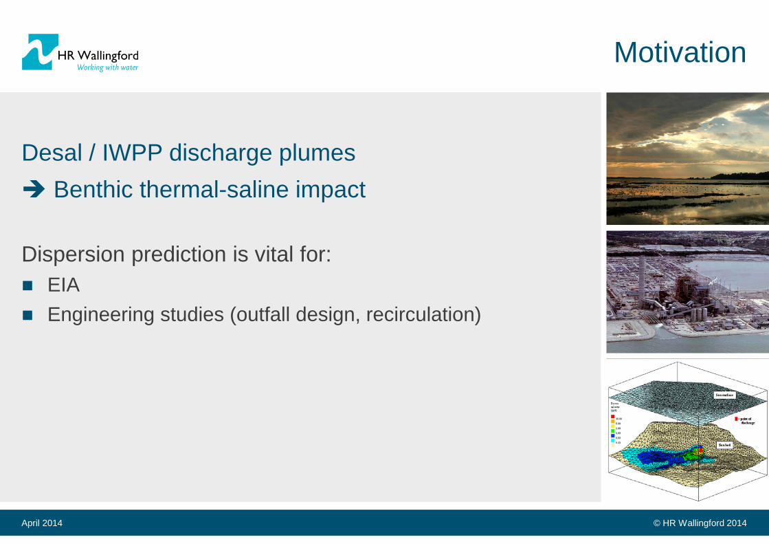
Motivation
Desal / IWPP discharge plumes Benthic thermal-saline impact Dispersion prediction is vital for: EIA Engineering studies (outfall design, recirculation)
April 2014
Page 4
© HR Wallingford 2014
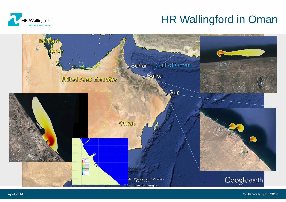
HR Wallingford in Oman
April 2014
Page 5
© HR Wallingford 2014
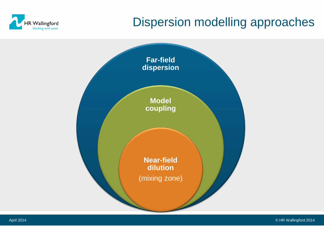
Far-field dispersion
Model coupling
Near-field dilution
(mixing zone)
Dispersion modelling approaches
April 2014
Page 6
© HR Wallingford 2014
Validated procedure
April 2014
Coupled studies are common
HR Wallingford framework: “Dense Jet Assessment Procedure”, Wood & Mead (2008)
Validated against newly available mid-/far-field data: “Validation of computational models for hypersaline and other dense marine discharges”, Wood et al, (2014)
Page 7
© HR Wallingford 2014
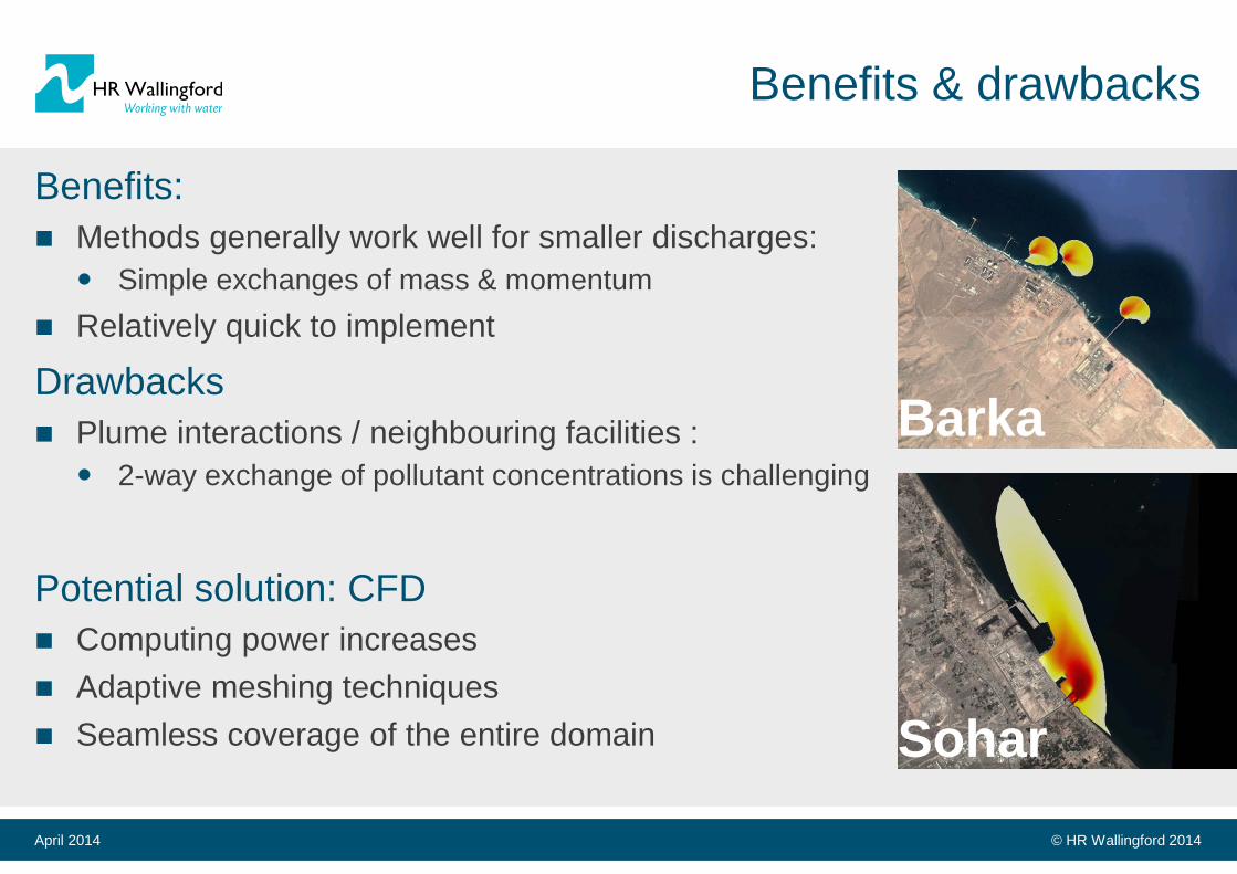
Benefits & drawbacks
Benefits: Methods generally work well for smaller discharges:
Simple exchanges of mass & momentum Relatively quick to implement
Drawbacks Plume interactions / neighbouring facilities :
2-way exchange of pollutant concentrations is challenging
Potential solution: CFD Computing power increases Adaptive meshing techniques Seamless coverage of the entire domain
April 2014
Barka
Sohar
Page 8
© HR Wallingford 2014
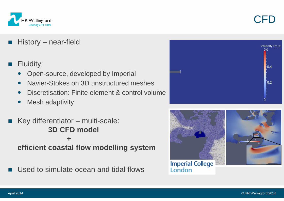
CFD
History – near-field Fluidity:
Open-source, developed by Imperial Navier-Stokes on 3D unstructured meshes Discretisation: Finite element & control volume Mesh adaptivity
Key differentiator – multi-scale:
3D CFD model + efficient coastal flow modelling system
Used to simulate ocean and tidal flows
April 2014
Page 9
© HR Wallingford 2014
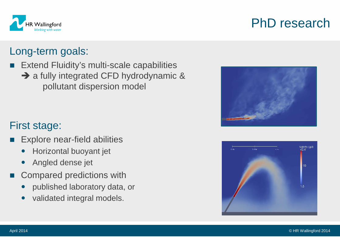
PhD research
Long-term goals: Extend Fluidity’s multi-scale capabilities a fully integrated CFD hydrodynamic & pollutant dispersion model
First stage: Explore near-field abilities
Horizontal buoyant jet Angled dense jet
Compared predictions with published laboratory data, or validated integral models.
April 2014
Page 10
© HR Wallingford 2014
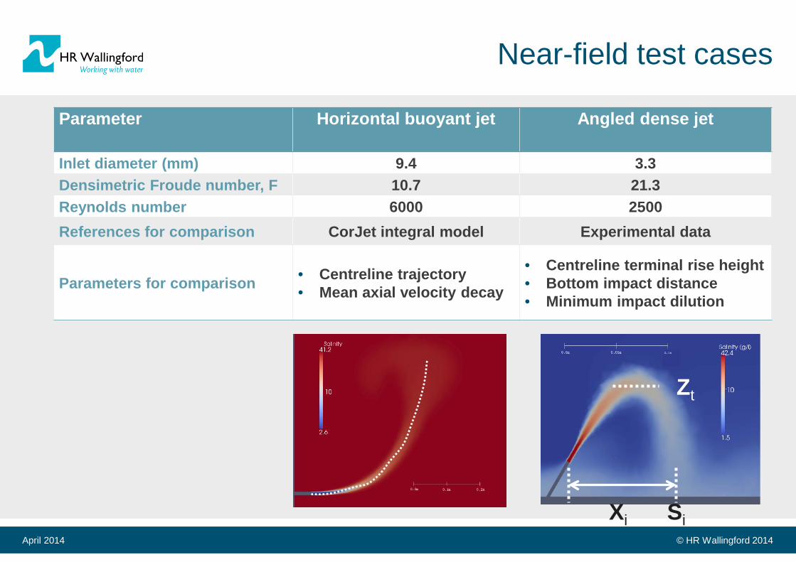
Near-field test cases
April 2014
Parameter Horizontal buoyant jet Angled dense jet
Inlet diameter (mm) 9.4 3.3 Densimetric Froude number, F 10.7 21.3 Reynolds number 6000 2500 References for comparison CorJet integral model Experimental data
Parameters for comparison • Centreline trajectory • Mean axial velocity decay
• Centreline terminal rise height • Bottom impact distance • Minimum impact dilution
Zt
Si Xi
Page 11
© HR Wallingford 2014
Numerical methods
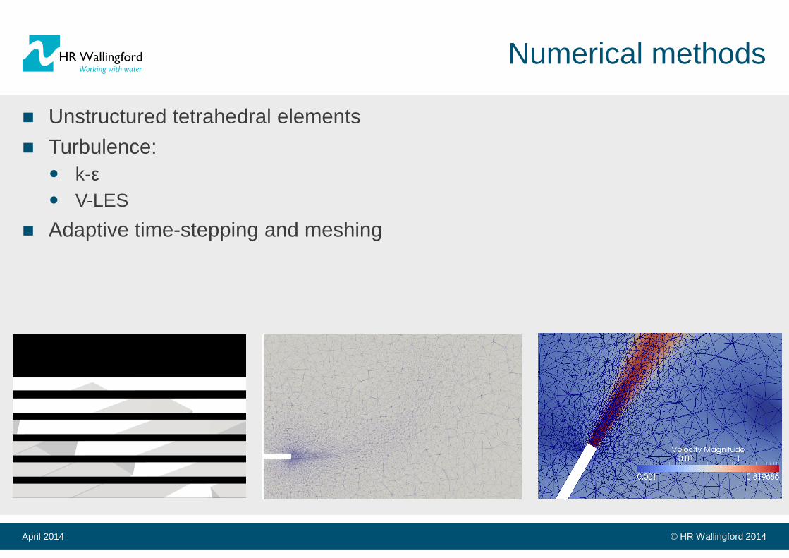
Unstructured tetrahedral elements Turbulence:
k-ε V-LES
Adaptive time-stepping and meshing
April 2014
Page 12
© HR Wallingford 2014
Horizontal buoyant jet
April 2014
Page 13
© HR Wallingford 2014
Horizontal buoyant jet
April 2014
Centreline trajectory
Centreline velocity decay
Page 14
© HR Wallingford 2014
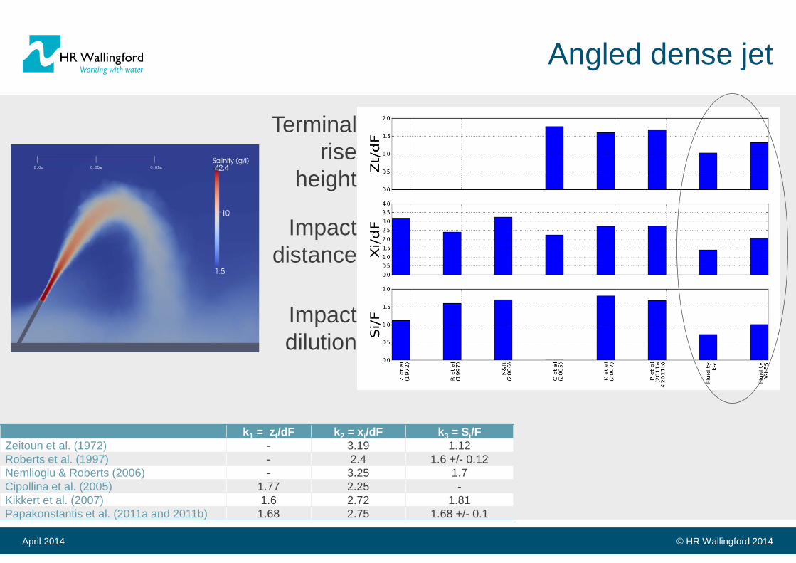
Angled dense jet
April 2014
Page 15
© HR Wallingford 2014
Angled dense jet
April 2014
k1 = zt/dF k2 = xi/dF k3 = Si/F Zeitoun et al. (1972) - 3.19 1.12 Roberts et al. (1997) - 2.4 1.6 +/- 0.12 Nemlioglu & Roberts (2006) - 3.25 1.7 Cipollina et al. (2005) 1.77 2.25 - Kikkert et al. (2007) 1.6 2.72 1.81 Papakonstantis et al. (2011a and 2011b) 1.68 2.75 1.68 +/- 0.1
Terminal rise
height
Impact distance
Impact dilution
Page 16
© HR Wallingford 2014
Summary
HR Wallingford uses a validated coupled modelling procedure involving Hydrodynamic models Near-field models
Future will involve more CFD
Preliminary work with Imperial College is encouraging:
Buoyant jet compares well (trajectories and dilutions) Dense case requires mesh refinement
Next steps of PhD: Adapt mesh to far-field Range of ambient currents Multiport diffusers
April 2014
Page 17
© HR Wallingford 2014
Thank you!
Matthew Wood Principal Scientist HR Wallingford [email protected]
David Robinson Imperial College London [email protected]
January 2014 Page 17